

Icom IC-FR9020, IC-FR9010 Instruction Manual
INSTRUCTION MANUAL
VHF P25 REPEATER
iFR9010
iFR9020
UHF P25 REPEATER
This device complies with Part 15 of the FCC Rules. Operation
is subject to the condition that this device does not cause harmful interference.
FORWARD
Thank you for purchasing this Icom repeater. The IC-FR9010/
FR9020
Icom’s state of the art technology and craftsmanship. With
proper care, this product should provide you with years of
trouble-free operation.
We want to take a couple of moments of your time to thank
you for making the
of choice, and hope you agree with Icom’s philosophy of
“technology first.” Many hours of research and development went into the design of your
This manual covers up to firmware version 71MDV024 and
DSPV326.
v h f /u h f p25 r e p e a t e r s are designed and built with
The IC-FR9010/FR9020
IC-FR9010/FR9020.
your repeater
R WARNING! NEVER let metal, wire or other ob-
jects touch any internal part or connectors on the rear
panel of the repeater. This may result in an electric
shock.
R WARNING! The antenna (s) used for this trans-
mitter must be fixed-mounted on outdoor permanent
structures with a separation distance of at least 6 meters from all persons during normal operation. The
peak conducted output power at each antenna terminal
must not exceed 250 Watts and the peak radiated output power must not exceed 1000 Watts EIPR. Users
and installers must ensure that FCC requirements for
satisfying RF exposure compliance are met. (See FCC
Rules Part 1, Sections 1307 and 1310)
IMPORTANT
READ THIS INSTRUCTION MANUAL carefully
and completely before attempting to operate the repeater.
SAVE THIS INSTRUCTION MANUAL—This in-
struction manual contains important safety and operating instructions for the IC-FR9010/FR9020 VHF/UHF
repeaters.
EXPLICIT DEFINITIONS
WORD DEFINITION
RWARNING!
CAUTION
NOTE
Personal injury, fire hazard or electric
shock may occur.
Equipment damage may occur.
If disregarded, inconvenience only. No risk
of personal injury, fire or electric shock.
PRECAUTIONS
R WARNING HIGH VOLTAGE! NEVER attach
an antenna or internal antenna connector during transmission. This may result in an electrical shock or burn.
R WARNING HIGH VOLTAGE! NEVER install
the antenna at any place that person touch the antenna easily during transmission. This may result in an
electrical shock or burn.
R WARNING! NEVER apply AC to the DC power
receptacle on the repeater rear panel. This could cause
a fire or damage the repeater.
R WARNING! NEVER apply more than 16 V DC,
such as a 24 V battery, to the DC power receptacle on
the repeater rear panel. This could cause a fire or damage the repeater.
CAUTION: NEVER expose the repeater to rain,
snow or any liquids.
DO NOT use or place the repeater in areas with
temperatures below –30°C (–22°F) or above +60°C
(+140°F). Be aware that temperatures can exceed
70°C (+158°F), resulting in permanent damage to the
repeater if left there for extended periods.
DO NOT place the repeater in excessively dusty envi-
ronments or in direct sunlight.
DO NOT put anything on top of the repeater. This will
obstruct heat dissipation. Place the repeater in a secure place to avoid inadvertent use by children.
BE CAREFUL! The heatsink will become hot when
operating the repeater continuously for long periods.
BE CAREFUL! If a linear amplifier is connected, set
the repeater’s RF output power to less than the linear
amplifier’s maximum input level, otherwise, the linear
amplifier will be damaged.
Use Icom microphones only. Other manufacturer’s
microphones have different pin assignments, and connection to the repeater may damage the repeater.
Approved Icom optional equipment is designed for optimal performance when used with an Icom repeater.
Icom is not responsible for the destruction or damage
to an Icom repeater in the event the Icom repeater is
used with equipment that is not manufactured or approved by Icom.
For U.S.A. only
CAUTION:
repeater, not expressly approved by Icom Inc., could
void your authority to operate this repeater under
FCC regulations.
Chan ges or modifi cations to thi s
i
NOTICE: The AMBE + 2 ™ voice coding Technology
WARNING
CAUTION
embodied in this product is protected by intellectual
property rights including patent rights, copyrights and
trade secrets of Digital Voice Systems, Inc. This voice
coding Technology is licensed solely for use within this
Communications Equipment. The user of this Technologies explicitly prohibited from attempting to extract,
remove, decompile, reverse engineer or disassemble
the Object Code, or in any other way convert the Object Code into a human readable form. U.S. Patents
Nos #5,870,405, #5,826,222, #5,754,974, #5,701,390,
#5,715,365, #5,649,050, #5,630,011, #5,581,656,
#5,517,511, #5,491,772, #5,247,579, #5,226,084 and
#5,195,166.
FCC INFORMATION
• FOR CLASS A UNINTENTIONAL RADIATORS
This equipment has been tested and found to comply
with the limits for a Class A digital device, pursuant to
part 15 of the FCC Rules. These limits are designed to
provide reasonable protection against harmful interference when the equipment is operated in a commercial
environment. This equipment generates, uses, and
can radiate radio frequency energy and, if not installed
and used in accordance with the instruction manual,
may cause harmful interference to radio communications. Operation of this equipment in a residential area
is likely to cause harmful interference in which case the
user will be required to correct the interference at his
own expense.
SAFETY TRAINING INFORMATION
Your Icom radio generates RF electromagnetic energy during transmit mode.
This radio is designed for and classified
as “Occupational Use Only”, meaning it
must be used only during the course of
employment by individuals aware of the hazards,
and the ways to minimize such hazards. This radio
is NOT intended for use by the “General Population” in an uncontrolled environment.
This radio has been tested and complies with the FCC
and IC RF exposure limits for “Occupational Use Only”.
In addition, your Icom radio complies with the following Standards and Guidelines with regard to RF energy
and electromagnetic energy levels and evaluation of
such levels for exposure to humans:
• FCC OET Bulletin 65 Edition 97-01 Supplement C,
Evaluating Compliance with FCC Guidelines for
Human Exposure to Radio Frequency Electromagnetic Fields.
• American National Standards Institute (C95.1-1992),
IEEE Standard for Safety Levels with Respect to
Human Exposure to Radio Frequency Electromagnetic Fields, 3 kHz to 300 GHz.
• American National Standards Institute (C95.3-1992),
IEEE Recommended Practice for the Measurement
of Potentially Hazardous Electromagnetic Fields– RF
and Microwave.
To ensure that your expose to RF electromagnetic energy is within the FCC
and IC allowable limits for occupational use, always adhere to the following
guidelines:
• DO NOT operate the radio without a proper antenna
attached, as this may damaged the radio and may
also cause you to exceed FCC and IC RF exposure
limits. A proper antenna is the antenna supplied with
this radio by the manufacturer or antenna specifically authorized by the manufacturer for use with this
radio.
• DO NOT transmit for more than 50% of total radio
use time (“50% duty cycle”). Transmitting more than
50% of the time can cause FCC and IC RF expo-sure
compliance requirements to be exceeded.
Electromagnetic Interference/Compatibility
During transmissions, your Icom radio generates RF
energy that can possibly cause interference with other
devices or systems. To avoid such interference, turn
off the radio in areas where signs are posted to do so.
DO NOT operate the transmitter in areas that are sensitive to electromagnetic radiation such as hospitals,
aircraft, and blasting sites.
Occupational/Controlled Use
The radio transmitter is used in situations in which persons are exposed as consequence of their employment
provided those persons are fully aware of the potential
for exposure and can exercise control over their exposure.
Icom, Icom Inc, and the Icom logo are registered trademarks of
Icom Incorporated (Japan) in Japan, the United States, the United
Kingdom, Germany, France, Spain, Russia and/or other countries.
All other products or brands are registered trademarks or trademarks of their respective holders.
ii

Votre radio Icom produit une énergie
électromagnétique de radiofréquences
(RF), en mode de transmission.
Cette radio est conçue pour un «usage
professionnel seulement» et classée
comme tel, ce qui signifie qu’elle doit être utilisée
uniquement dans le cadre d'un travail par des personnes conscientes des dangers et des mesures
visant à minimiser ces dangers. Elle N’EST PAS
conçue pour une«utilisation grand public», dans
un environnement non contrôlé.
Cet appareil a été évalué et jugé conforme, aux limites
d’exposition aux RF de la FCC et d’IC, pour une «utilisation grand public». En outre, votre radio Icom satisfait les normes et directives qui suivent en matière de
niveaux d'énergie et d’énergie électromagnétique de
RF et d’évaluation de tels niveaux en ce qui concerne
l’exposition humaine:
• Supplément C, édition 97-01, du Bulletin OET n° 65
de la FCC,«Evaluating Compliance with FCC Guidelines for Human Exposure to Radio Frequency Electromagnetic Fields».
• Norme de l’American National Standards Insti-
tute(ANSI): IEEE C95.1-1992 sur les niveaux de
sécurité compatibles avec l’exposition humaine aux
champs électromagnétiques de radio fréquences (3
kHz à 300 GHz).
• Norme de l’ANSI: IEEE C95.3-1992 sur la méthode
d’évaluation recommandée du champ magnétique
potentiellement dangereux des radiofréquences et
des micro-ondes.
Afin de vous assurer que votre exposition à une énergie électromagnétiquede RF se situe dans les limites permises par la FCC et d’IC pour
une utilisation grand public, veuillez
en tout temps respecter les directivessuivantes:
• NE PAS faire fonctionner la radio sans qu’une antenne
appropriée y soit fixée, car ceci risque d’endommager
la radio et causer une exposition supérieure aux limites établies par la FCC et d’IC. L’antenne appropriée
est celle qui est fournie avec cette radio par le fabricant ou une antenne spécialement autorisée par le
fabricant pour être utilisée avec cette radio.
• NE PAS émettre pendant plus de50% du temps
total d’utilisation de l’appareil («50% du facteur
d'utilisation»). La notion «50% du facteur d’utilisation»
s’applique également au mode VOX/PTT. Émettre
pendant plus de 50% du temps total d’utilisation peut
causer une exposition aux RF supérieure aux limites
établies par la FCC et d’IC. Lorsque le voyant DEL
rouge s’allume, cette radio est en train d’émettre. La
radio émettra si vous appuyez sur le bouton du microphone.
Interférence électromagnétique et compatibilité
En mode de transmission, votre radio Icom produit de
l’énergie de RF qui peut provoquer des interférences
avec d’autres appareils ou systèmes. Pour éviter de
telles interférences, mettez la radio hors tension dans
les secteurs où une signalisation l’exige. NE PAS faire
fonctionner l’émetteur dans des secteurs sensibles au
rayonnement électromagnétique tels que les hôpitaux,
les aéronefs et les sites de dynamitage.
Usage professionnel/contrôlé
Ce radio émetteur est utilisé dans des cas où des personnes sont exposées en raison de leur travail, pourvu
qu’elles soient conscientes du risque d’exposition et
qu’elles puissent exercer un contrôle sur cette exposition.
iii

TABLE OF CONTENTS
FORWARD ................................................................. i
IMPORTANT .............................................................. i
EXPLICIT DEFINITIONS ............................................ i
PRECAUTIONS .......................................................... i
SAFETY TRAINING INFORMATION .........................ii
FCC INFORMATION ..................................................ii
TABLE OF CONTENTS ............................................iv
1 LCD DISPLAY ..................................................... 1
2 LED DISPLAY ...................................................... 1
3 KEY CONTROLS ................................................. 1
3.1 Key entry without [SHIFT] key ........................ 1
3.2 Key entry following [SHIFT] key ..................... 1
4 CONTROL KNOB ................................................ 2
4.1 VOLUME ........................................................ 2
4.2 SQUELCH CONTROL .................................. 2
4.3 LCD BACKLIGHT DIMMER ........................... 2
4.4 LCD BACKLIGHT TIMER ............................... 2
5 CHANNEL SELECTION ...................................... 2
6 P25 CALLING SELECTION (Digital Base Mode
Only) .................................................................... 2
6.1 INDIVIDUAL CALL ENTRY (Digital Base Mode
Only) ...............................................................3
7 P25 PTT MODE ................................................... 3
8 P25 CONVENTIONAL CONTROL SIGNALLING
(SBC) (DIGITAL BASE MODE ONLY) ................ 3
8.1 EMERGENCY MODE TX .............................. 3
8.2 CALL ALERT .................................................. 4
8.3 RADIO CHECK .............................................. 4
8.4 RADIO INHIBIT .............................................. 4
8.5 RADIO UNINHIBIT ......................................... 4
8.6 STATUS UPDATE .......................................... 4
8.7 STATUS REQUEST ....................................... 4
8.8 PREDEFINED MESSAGES ........................... 5
8.9 RADIO MONITOR .......................................... 5
8.10 SBC LOG ..................................................... 5
9 P25 SQUELCH ADJUSTMENT ........................... 5
10 TALKGROUP ALIAS ID ...................................... 5
11 KEY-LOCK ........................................................... 6
12 MANUAL CWID START AND STOP ................... 6
13 DTMF ENCODE ................................................... 6
14 ANALOG CHANNEL DATA ................................ 6
16 BAR GRAPH/CHANNEL DISPLAY .................... 7
17 LCD BACKLIGHT TOGGLE ................................ 7
18 CHANGING TX POWER ...................................... 7
20 EMERGENCY CALL RECEPTION ...................... 8
21 REPEAT MODE ................................................... 8
21.1 ANALOG ...................................................... 8
21.2 DIGITAL ....................................................... 8
21.3 MIXED .......................................................... 8
22 BASE MODE ........................................................ 8
22.1 ANALOG ...................................................... 8
22.2 DIGITAL ....................................................... 8
22.3 MIXED .......................................................... 8
23 REMOTE CONTROL ........................................... 8
24 DISPLAYING THE FIRMWARE VERSIONS ....... 9
25 DISPLAYING THE SERIAL NUMBER ................ 9
26 DISPLAYING THE PROGRAMMING SOFTWARE
VERSION ............................................................. 9
27 DATA CHECK ...................................................... 9
28 ERROR MESSAGES ........................................... 9
29 FIRMWARE ERROR DETECTION ...................... 9
30 RS-232 ERROR DETECTION ............................ 10
31 DSP ERROR DETECTION ................................ 10
32 OPTION PORT PINOUT .................................... 11
iv
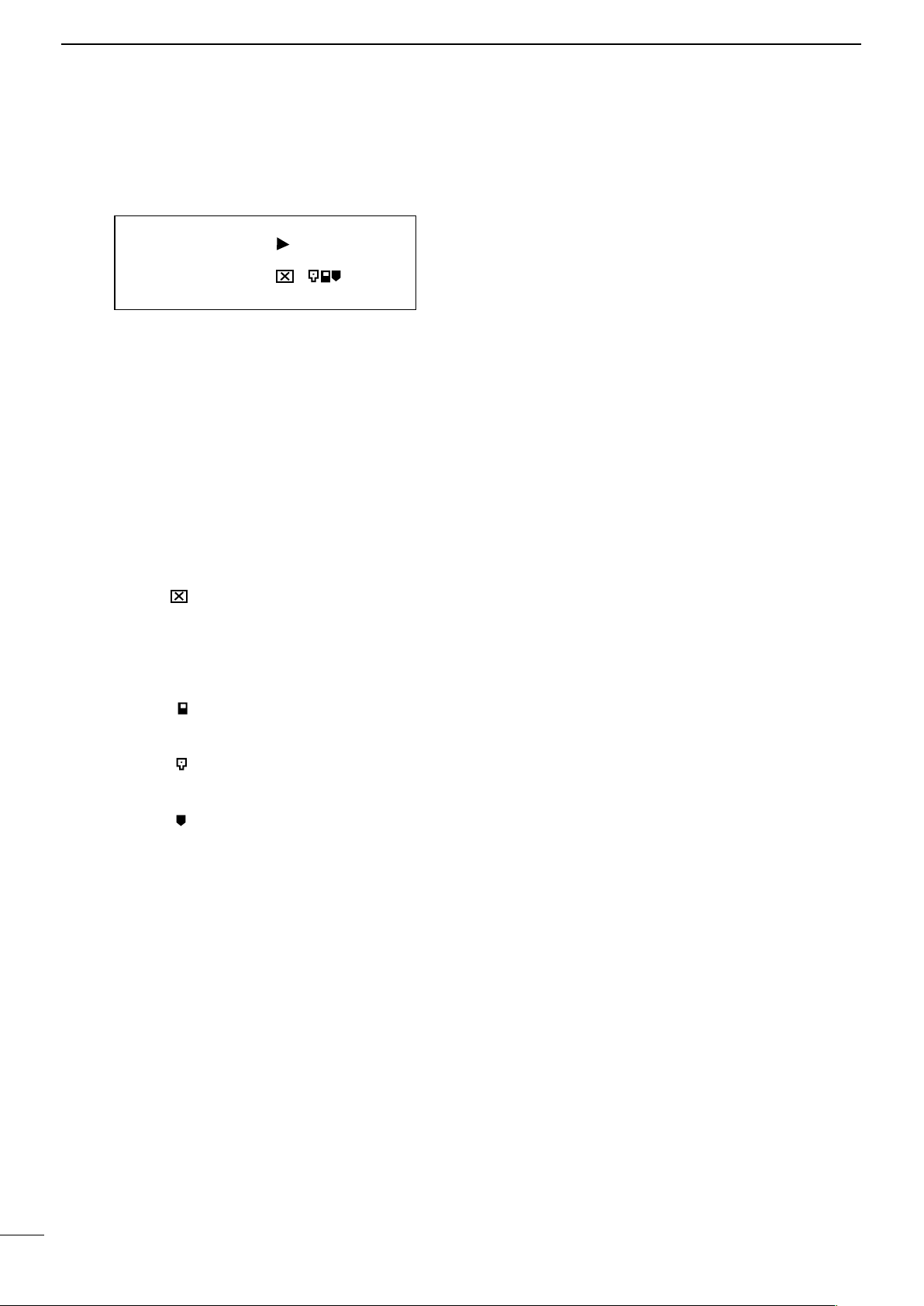
1 LCD DISPLAY
3 KEY CONTROLS
LCD display consists of 4 x 20 characters as shown.
RX = = = = = = = = = =
TX = = = = = = = = = =
C001 TAC 2 MD N
GPC 500
Line 1: The incoming RSSI with 10 steps
Line 2: The output power levels with 10 steps
Line 3: The left 4 letters show channel numbers.
The middle 8 letters shows the channel name.
(If not programmed, it will be blank.)
The right 4 letters displays the status of the radio as described below.
a. RX mode:
M = Mix, both analog and digital can be
received
D = Only digital can be received
b. TX mode:
D = PTT digital transmission
A = PTT analog transmission
c. Monitor mode:
= Monitor off
S = Selective squelch
d. P25 squelch:
N = Normal squelch
S = Selective squelch
e. Low Voltage Icon:
= Low Voltage state (Icon flashes with
ALM LED)
f. Key lock mode:
= Key lock (Not displayed if in Low
Voltage alarm)
g. Shift mode:
= SHIFT KEY ICON (reverts to normal
within 2 seconds)
Line 4: The left 2 letters show GPC (GROUP CALL),
AC (ALL CALL), IC (INDIVIDUAL CALL). The
right 18 letters displays the GROUP NAME, INDIVIDUAL NUMBERS, and so on.
2 LED DISPLAY
The IC-FR9010/FR9020 has 5 LED's from left to
right.
DIGI = The LED is ON when receiving a digital sig-
nal
REP = The LED is ON when in repeat mode
(The IC-FR9010/FR9020 can be programmed
for SIMPLEX - SEMIDUPLEX - DUPLEX REPEATER on a per channel basis.)
ALM = The LED flashes when an error on either TX
or RX occurs
TX = The LED is ON when in Transmit
BUSY = The LED is ON when receiving a signal
3.1 Key entry without [SHIFT] key
[0]–[9] = Channel numbers and individual call
address (target address)
[A] = P25 calls (Group Call, All Call, and
Individual Call)
[B] = The beginning and the end of indi-
vidual call number
[C] = TX Transmit mode (Clear or Secure),
only models with encryption
[D] = P25 mode (analog or digital TX)
[Q] = Cancel channel number, individual
number
[#] = Ending channel number, individual
number
[CH] = Channel number entry, depress CH,
then 0–9 for channels
[F] (Scan) = P25 Conventional Control Messages
(SBC)
[MON] = monitor ON or OFF
Rotary knob = Volume, Squelch, Back Light Dimmer
and Timer
3.2 Key entry following [SHIFT] key
[0] = P25 test mode start and finish
[1] = Backlight ON/OFF
[2] = TX power HIGH/LOW
[3] = Talkaround ON/OFF
[4] = Change
[5] = No function
[6] = No function
[7] = Indicates Analog channel data
[8] = Key lock ON/OFF
[9] = No function
[A] = Manual CWID send key
[B] = Programmed CWID Start/Stop key
[C] = Cryptogram Test
[D] = No function
[Q] = Indicating P25 data (while de-
pressed)
[#] = DTMF Entry
[CH] = Toggle Bar-Graph or TX RX Fre-
quencies
[F] (Scan) = SBC (Conventional Control Messag-
es) Log/Emergency Call
[MON] = P25 squelch normal or selective and
analog MONITOR modes
1
 Loading...