

Page 1
INSTRUCTIONS
Screws (3×12)Screws (3×8)
Flat cable
Connector caps
Dust protectors
Rear panel Rear panel
holder
Projections
Holes
J8
J1
w
q
P
0
P
1
P
2
P
3
P
4
P
0
P
1
P
2
P
3
P
4
TRUNKING/NETWORK CONTROLLER
UC-FR5000
Thank you for purchasing the UC-FR5000 TRUNKING /
NETWORK CONTROLLER
. The controller is designed to be
installed into the IC-FR5000/IC-FR6000 series VHF /
UHF FM REPEATERS
digital trunking operation on the repeater
and enables the on-line control and
.
Before installation, please carefully read these instructions and repeater’s instruction manual.
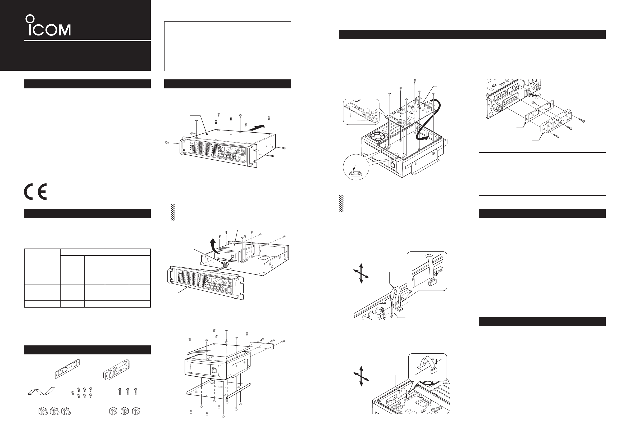
INSTALLATION
• Installing the UC-FR5000
Install the controller into the channel module using six
of the seven supplied screws (3×8).
• Be sure to match the holes in the controller to the projec-
tions on the channel module’s chassis.
• Attaching the rear panel
q
Attach the supplied rear panel to the rear panel
holder using one of the seven supplied screws (3×8).
w Attach the rear panel and holder set to the channel
module using the three supplied screws (3×12).
PRECAUTIONS
R WARNING! Turn OFF the repeater before install-
ing the controller. Otherwise a fire, electric shock may
occur, or the repeater could malfunction.
CAUTION: NEVER expose the repeater and controller to rain, snow or any liquids.
CAUTION: NEVER let metal, wire or other objects
touch any internal part of the controller.
CAUTION: Install the controller in only the specified
repeater.
Be careful! When you install the controller, wear
gloves to avoid cutting your hand on the sharp edges
of the repeater.
About CE
The UC-FR5000 complies with the essential requirements of the 2004/108/EC directive for Electromagnetic Compatibility.
CONFIGURATIONS
The controller enables the repeater to be used for the
following modes, depending on the configurations.
(This table is shown in controllers whose revision
number is 3.5 or later. Ask your dealer for details.)
Conventional Trunking Conventional Trunking
UC-FR5000#01
UC-FR5000#02
( CF - F R 5 0 00MC is
installed)
UC-FR5000#03
( CF- FR5000MT is
installed)
UC-FR5000#04
1
*
When the optional RS-FS10 r e m o t e c o m m u n i c a t o r is used,
either the CF-FR5000MC or CF-FR5000MT is required.
2
*
Either the optional CF-FR5000MC or CF-FR5000MT is
required.
3
*
The optional CF-FR5000MT is required.
SUPPLIED ACCESSORIES
Single Site Multi Site
✔*
1
✔ ✔*
2
✔ ✔ ✔ ✔*
✔ ✔ ✔ ✔
1
✔*
✔ ✔*
2
✔*
✔*
OPENING CASE
Controller
Channel module
q Unscrew the seven screws from the top, and the
two screws on both sides of the repeater, then
slide the top cover off in the direction of the arrow.
Top cover
Rear panel
Rear panel holder
Repeater
w Disconnect the control cable from the channel
module. Then, unscrew the seven screws which
affix the channel module to the repeater chassis,
and remove it.
The front panel is removed in this illustration so the de-
tail is easier to see. You can remove the channel module without removing the front panel of the repeater.
Channel module
Control cable
Channel module
• Connecting the at cable
Make sure to insert the flat cable with the metal
strips facing the edge of the PCB, and not the opposite way.
q Turn the channel module upside down.
Insert one end of the flat cable into J8 on the PCB
of the channel module. Then, carefully pass the flat
cable through the opening of the channel module’s
chassis to the top side.
✔For your information
When you have installed a channel extension module (optional
UR-FR5000/UR-FR6000 series
), an
additional controller allows you to control each channel module from a PC console in the Conventional/
Trunking operation mode.
ABOUT THE CF CARD
The UC-FR5000 #02/#03 comes with a CF card inserted in the controller’s CF card slot. Please take notice of the following.
CAUTION: NEVER turn OFF the repeater while the
data is being transferred. Otherwise, the data on the
CF card may become corrupted.
CAUTION: Use the CF card only in the UC-FR5000.
Inserting the CF card into other equipment may corrupt the card’s data.
NOTE: When no CF card is inserted, the controller
cannot be used for Multi Site Conventional/Trunking
mode operation.
OPTION
CF-FR5000MC CF CARD
Upgrades the UC-FR5000#01 to enable the Multi Site
Conventional mode.
3
3
Repeater
Front panel
3
e
Unscrew the eight screws from the top, the nine
screws from bottom, and the three screws from rear
Front
Bottom
Flat cable
Rear
To p
Opening
of the channel module. Then remove each cover
from it.
w Turn over the channel module.
Carefully pull out the other end of the flat cable
from the opening, and then insert it into J1 on the
controller.
Same as that supplied with #02.
Channel module
Front
To p
Flat cable
CF-FR5000MT
Upgrades the UC-FR5000#01 to enable the Multi Site
Conventional/Trunking mode.
CF CARD
Same as that supplied with #03.
Rear
Bottom
Icom, Icom Inc. and the Icom logo are registered trademarks of Icom Incorporated (Japan) in Japan, the United States, the United Kingdom, Germany,
France, Spain, Russia and/or other countries.
JavaScript is a registered trademark of Sun Microsystems, Inc.
All other products or brands are registered trademarks or trademarks of their
respective holders.
Page 2
Assembling the unit
P
0
P
1
P
2
P
3
P
4
P
0
P
1
P
2
P
3
P
4
PC console
to an Ethernet port
q
w
BUS-1 BUS-2 LAN
Hub
*This illustration
is described with
the UT-105.
q Re-attach the top and bottom covers of the chan-
nel module, and then tighten all the screws.
Channel module
w
Re-install the channel module and the screws to
their original positions, and then connect the control
cable of the repeater’s front panel to the channel
module.
Channel module
Control cable
Front panel
e Re-attach the top cover of the repeater, and then
tighten the seven screws for the top and the two
screws on both sides of the repeater.
Top cover
Repeater
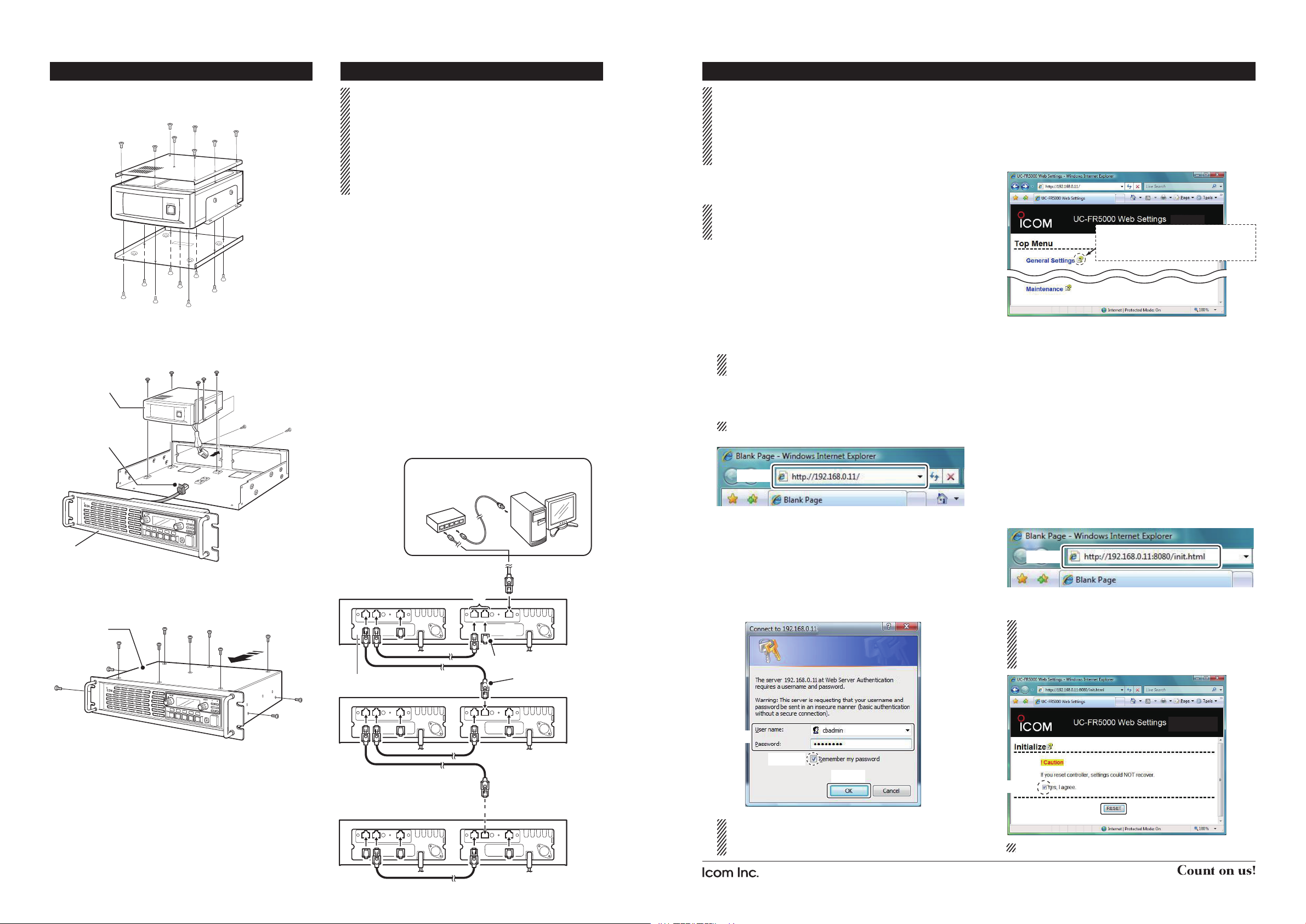
Connection
CAT-5 straight cables and a Hub (or a router) are
required for connection (purchase separately).
BE SURE to cover each connected cable with a
supplied dust protector. Even if the cable has its own
cover, replace it with the supplied dust protector.
KEEP the supplied connector caps attached when
the connectors are not in use, to avoid getting bad
contacts from dust and moisture.
Each controller has a LAN connector and two BUS
connectors.
q [LAN] connector
For an Ethernet connection. Connect the controller
to an Ethernet (LAN) port of a PC console through
a Hub (or a router).
In trunking mode operation, the controller at one
end of the chain must be connected. You can control the controller and all others in the chain from
the PC console.
w [BUS] connectors (BUS-1, BUS-2)
For data communication between the controllers in
trunking mode operation, either BUS-1 or BUS-2
can be used. They enable the controllers to be “daisy-chained” together, and form a network that allows trunking and other data to pass among them.
* The illustration below describes one example of a con-
nection for trunking mode operation.
Repeater
Connector cap
Channel extension module
Dust protector
The Setting screen of the UC-FR5000
Internet Explorer 6.0 or later is required to correctly
open the setting screen of the controller. The following instructions are based on using Internet Explorer 7.0.
JavaScript must be installed to open the side menu
and help window of the Setting screen..
• Accessing the setting screen
It takes 2 to 3 minutes (typical) for the controller to
start up the software. Please wait to launch the web
browser until the operating system is up.
q Connect the controller to a PC console with a
CAT-5 straight cable (See “Connection” to the left),
and then turn ON the repeater.
w Before accessing the Setting screen, change the
IP address of the PC console to 192.168.0.XXX*
(Subnet mask should be 255.255.255.0) using the
Control Panel.
* Input 1 to 254 (except 11) instead of XXX.
Refer to the Operating System’s manual for de-
.
tails
e
Open your web browser, enter “http:// 192.168.0.11/”
(default IP address of the UC- FR5000) into the address bar, and then push the [Enter] key.
Ask your system administrator for details.
• The Login Authentication screen appears.
Enter
r
Enter “cbadmin” (default user name) and “ucfr5000”
(default password) in their respective input field in
the Login Authentication screen, and then click the
[OK] button.
If you want the screen to remember not only the
user name but also the password, check the box,
“Remember my password”.
• The Opening screen appears.
• Opening the help window
The Setting screen of the controller has a help window to describe functions and settings.
When you don’t understand the meaning of an item,
or how to configure the controller, click a question
mark icon on the screen to open the help window.
Click to open the help window for
“General Settings,” for example.
• Initialization
You can reset all set contents, including the network
settings of the controller, to the factory default from a
PC console.
q Connect the controller to a PC console, and then
turn ON the repeater.
w
Open your web browser, enter the initialize address
into the address bar, and then push the [Enter] key.
• Initialize address: http://(IP address):8080/init.html
• When the IP address of the controller is 192.168.0.11*,
enter “http://192.168.0.11:8080/init.html” as the initialize
address.
* The IP address is an example only. Check the IP ad-
dress of the controller.
• The initialize screen appears.
Enter
e Click the [RESET] button after checking the box,
“Yes, I agree.” to initialize the settings.
If you use the UC-FR5000 #03, you can select
whether or not to reset the Network settings as
well as other settings. Please refer to the help
window for details.
Repeater
Enter
Check
Up to 30 channel modules
with controllers can be daisychained.
You can change the user name and password in
the Setting screen. Refer the help window of the
Setting screen for details.
1-1-32 Kamiminami, Hirano-ku, Osaka 547-0003, Japan
Click
Check
Click
This screen slightly differs, depending on the version.
A-6691H-1EX-t Printed in Japan
© 2008–2012 Icom Inc.
 Loading...