

Page 1
INSTRUCTION MANUAL
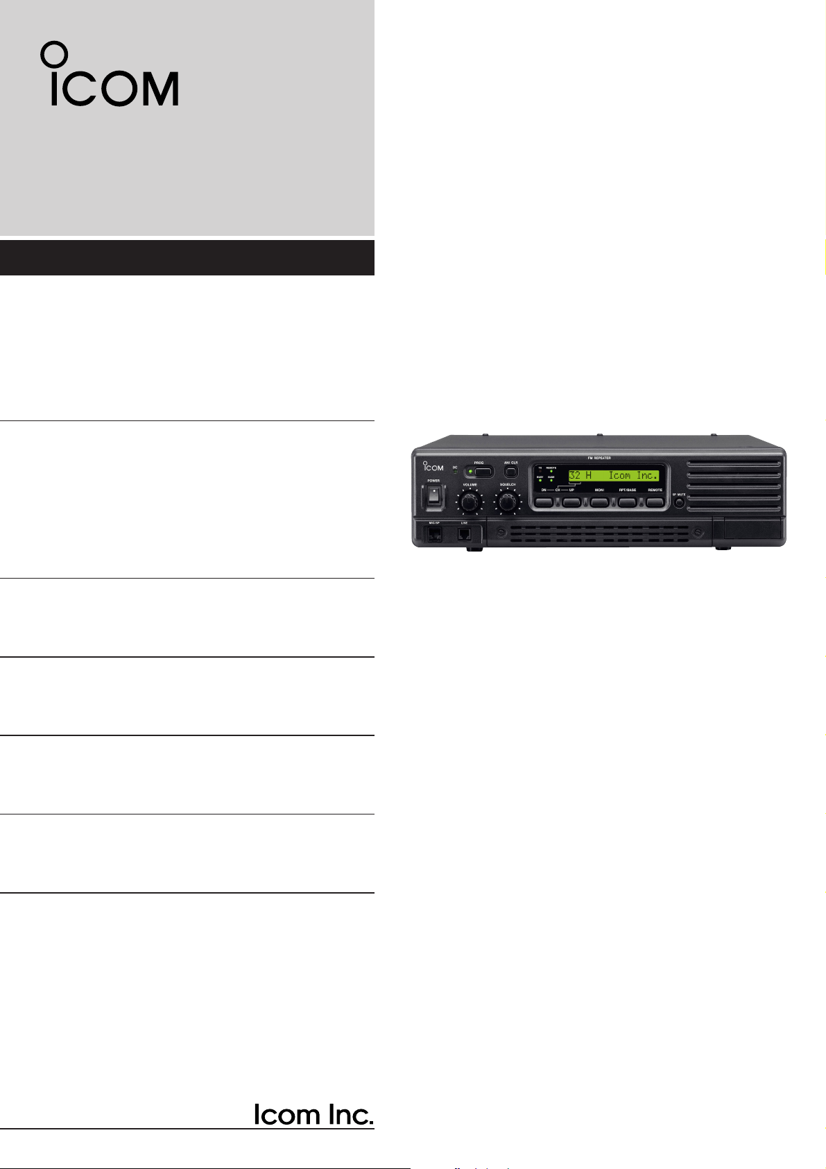
VHF FM REPEATER
iFR3100
UHF FM REPEATER
iFR4100
Page 2

i
IMPORTANT
READ THIS INSTRUCTION MANUAL
CAREFULLY before attempting to operate the re-
peater.
SAVE THIS INSTRUCTION MANUAL– This
manual contains important safety and operating instructions for the IC-FR3100/FR4100 series.
EXPLICIT DEFINITIONS
R WARNING HIGH VOLTAGE! NEVER at-
tach an antenna or internal antenna connector during
transmission. This may result in an electrical shock or
burn.
RWARNING HIGH VOLTAGE! NEVERinstall
the antenna in any place that a person can touch the
antenna easily during transmission. This may result in
an electrical shock or burn.
R NEVER apply AC to the [BATTERY] terminals on
the repeater rear panel. This could cause a fire or
damage the repeater.
R NEVER apply more than 16 V DC, such as a 24 V
battery, to the [BATTERY] terminals on the repeater
rear panel. This could cause a fire or damage the repeater.
R NEVER let metal, wire or other objects touch any
internal part or connectors on the rear panel of the repeater. This may result in an electric shock.
R NEVER expose the repeater to rain, snow or any
liquids.
AVOID using or placing the repeater in areas with tem-
peratures below –25°C or above +55°C.
AVOID placing the repeater in excessively dusty envi-
ronments or in direct sunlight.
AVOID putting anything on top of the repeater. This will
obstruct heat dissipation.
Place the repeater in a secure place to avoid inadvertent use by children.
BE CAREFUL! The heatsink will become hot when op-
erating the repeater continuously for long periods.
BE CAREFUL! If a linear amplifier is connected, set
the repeater’s RF output power to less than the linear
amplifier’s maximum input level, otherwise, the linear
amplifier will be damaged.
Use Icom microphones only (optional). Other manufacturer’s microphones have different pin assignments,
and connection to the IC-FR3100/FR4100 series may
damage the repeater.
CAUTION: This repeater is intended for use as a fixed
base station with the antenna located outdoors on the
rooftop or on an antenna tower.
PRECAUTION
WORD
R
WARNING
CAUTION
NOTE
DEFINITION
Personal injury, fire hazard or electric
shock may occur.
Equipment damage may occur.
If disregarded, inconvenience only.
No risk of personal injury, fire or
electric shock.
Icom, Icom Inc. and the logo are registered trademarks
of Icom Incorporated (Japan) in the United states, the United
Kingdom, Germany, France, Spain, Russia and/or other countries.
Page 3

ii
FORWARD
Thank you for purchasing this Icom product. The ICFR3100/FR4100
VHF/UHF FM REPEATER
is designed
and built with Icom’s state of the art technology and
craftsmanship. With proper care, this product should
provide you years of trouble-free operation.
We want to take a couple of moments of your time to
thank you for making the IC-FR3100/FR4100 your repeater of choice, and hope you agree with Icom’s philosophy of “technology first.” Many hours of research
and development went into the design of the ICFR3100/FR4100 series.
D
FEATURES
❍ 25 W continuous full duty cycle operation
This repeater looks as good as it performs. A rugged
heatsink, large cooling fans and a high performance
power module provide the repeater with a stable
25 W at full duty cycle operation.
❍
Automatic battery backup system
A built-in backup system supports automatic switching to an external power supply (13.2 V DC) if the
AC power supply fails.
❍ Multiple CTCSS & DTCS tone memories
with multiple memory channels
Up to 16 CTCSS/DTCS tones (TX/RX tones respectively) can be programmed in a channel. This feature allows you to share a channel with multiple user
groups. You can also give priority/exclusive use to a
specified group simply by programming different
tones to another memory channel. Ideal for many
different applications.
❍ Built-in 2-Tone, 5-Tone, DTMF encoder &
decoder
Multiple signaling systems are equipped as standard. These systems are fully compatible with Icom
F-series radios.
❍ Telephone interconnect capability
❍ DTMF remote control capability
You can control the repeater from a remote location
over the air or over a phone line with DTMF.
❍ Other features
- PC programmable
- Wall or 19 inch rack mount (optional MB-77/MB-78)
- Optional Voice Scrambler Unit (UT-109 #01/UT-110
#01) for base operating mode
SUPPLIED ACCESSORIES
The following accessories are supplied with the ICFR3100/FR4100 series
q AC power cable (OPC-492) ……………………… 1
w Spare fuse (FGB 1 A)……………………………… 1
e Spare fuses (ATC 20)……………………………… 2
EXPLICIT DEFINITIONS
IMPORTANT ............................................................ i
EXPLICIT DEFINITIONS ......................................... i
PRECAUTION ......................................................... i
FORWARD .............................................................. ii
SUPPLIED ACCESSORIES ................................... ii
TABLE OF CONTENTS .......................................... ii
1PANEL DESCRIPTION ......................... 1–4
■ Front panel .................................................... 1
■ Rear panel ..................................................... 2
2 INST ALLATION AND
CONNECTIONS .................................. 5–10
■ Unpacking ..................................................... 5
■ Selecting a location ....................................... 5
■ Antenna connection ....................................... 5
■ Duplexer ........................................................ 5
■ Grounding ...................................................... 5
■ Required connections .................................... 6
■ Advanced connections .................................. 7
■ Power ............................................................ 8
■ Mounting the repeater ................................... 8
3 OPTIONAL UNIT INSTALLATION ...........11
■ Opening the repeater’s case ....................... 11
■ Voice scrambler unit installation .................. 11
4 OPERATION ............................................ 12
■ Turning power ON ....................................... 12
■ Receiving and transmitting .......................... 12
5 MAINTENANCE ................................ 13–14
■ Troubleshooting ........................................... 13
■ Fuse replacement ........................................ 14
6 SPECIFICA TIONS AND OPTIONS ... 15–16
■ Specifications .............................................. 15
■ Options ........................................................ 16
7 ABOUT CE ........................................ 17–20
q
we
Page 4
1
PANEL DESCRIPTION
1
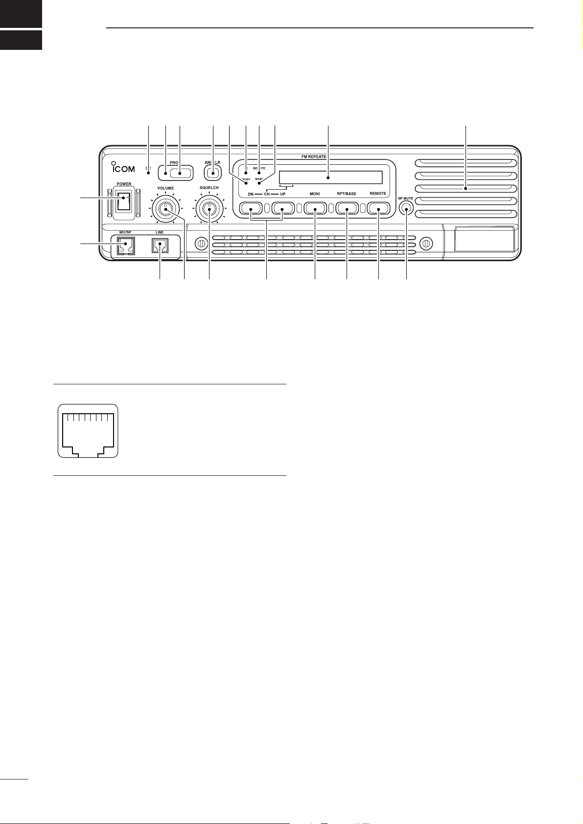
■ Front panel
q POWER SWITCH [POWER]
Toggle to turn the repeater power ON or OFF.
w
MICROPHONE/SPEAKER CONNECTOR [MIC/SP]
This 8-pin modular jack accepts the optional microphone.
q +9 V DC output (Max. 10 mA)
w I/O port for PC programming
e NC
r M PTT (Input port for TX control)
t Microphone ground
y Microphone input
u Ground
i M MONI (Input port for monitor control)
e LINE CONNECTOR [LINE]
This 4-pin modular jack allows connection of a 2
wire system telephone cable.
• See p. 7 for line connector information.
r VOLUME CONTROL[VOLUME] (p. 12)
Adjusts the audio output level.
t SQUELCH CONTROL[SQUELCH]
➥While in base operating mode, adjusts the
squelch threshold level. (p. 12)
➥While in repeater operating mode, this knob is not
activated.
y CHANNELSELECT SWITCHES [DN/UP]
Push either switch to select the operating channel.
u MONITOR SWITCH [MONI]
➥Push to monitor the operating frequency.
i MODE SELECT SWITCH [RPT/BASE]
Toggles the repeater or base operating mode when
pushed.
• When setting up a repeater system using ICFR3100/FR4100 only, select a repeater operating mode.
• When using IC-FR3100/FR4100 as a full (or half) duplex
transceiver, or setting up a repeater system connecting
an external controller, select a base operating mode.
o REMOTE CONTROLSWITCH [REMOTE]
Toggle to activate or inactivate the remote control
operation when pushed.
!0 AF MUTE CONTROL[SP MUTE]
Mutes the audio output.
!1 INTERNALSPEAKER
Monitors received signals.
!2 BASE OPERATING MODE INDICATOR
Lights green while in base operating mode.
!3 REMOTE CONTROLMODE INDICATOR
Lights green while in remote control operation
mode.
!4 TRANSMIT INDICATOR
Lights red while transmitting.
!5 BUSYINDICATOR
Lights green while receiving a signal or when the
noise squelch is open.
q
i
!8!9
q
w
e t y u i o !0
r
!2 !1!3!4!5!6!7
Function display (p. 2)
Page 5
2
1
PANEL DESCRIPTION
!6 ANI CLEAR SWITCH [ANI CLR]
Push for 1 sec. to clear the received ANI ID indication on the display and return to the original indication.
NOTE: This switches’ function is not available for
some versions.
!7 DEALER-PROGRAMMABLE SWITCH [PROG]
Toggles the pre-programmed function ON or OFF
when pushed.
!8 PROGRAMMED FUNCTION INDICATOR
Lights green while the pre-programmed function is
activated.
!9 DC INDICATOR
Lights green during DC operation.
DD
Function display
q MEMORY CHANNEL INDICATOR
Shows the selected memory channel.
w TRANSMIT POWER INDICATOR
Shows the output power level.
e AUDIBLE INDICATOR
“@” appears during audible condition, disappears
during inaudible condition. (During audible condition, the audio mute is cancelled.)
r ALPHANUMERIC INDICATORS
Shows a variety of text or code information.
32H H@HICOMH INC.
q
w
e
r
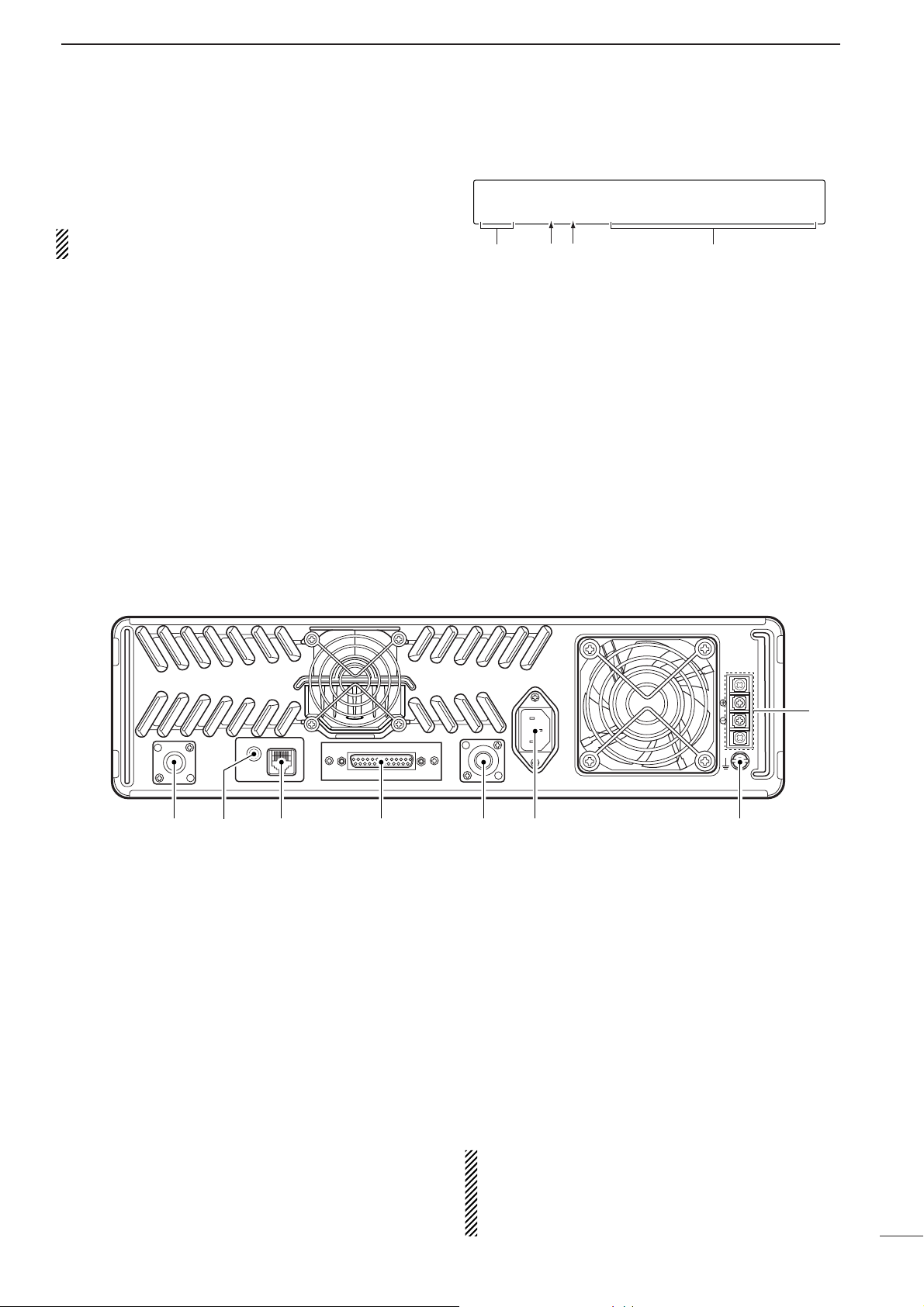
■ Rear panel
q TRANSMIT ANTENNACONNECTOR [TX/TX•RX]
➥ Connects a transmit antenna (impedance: 50 Ω)
and outputs transmit signals.
➥ When installing an optional internal duplexer
(supplied by a third party), this connects the
transmit/receive to an antenna.
w
EXTERNAL SPEAKER CONNECTOR [EXT SP]
Accepts a 4 Ω external speaker.
e REMOTE CONNECTOR [REMOTE]
Connects to the remote controller.
• See p. 3 for remote connector information.
r ACCESSORY CONNECTOR [ACC]
Connects to the remote controller.
• See pgs. 3, 4 for accessory connector information.
t RECEIVE ANTENNACONNECTOR [RX]
➥ Connects a receive antenna (impedance: 50 Ω)
and inputs received signals.
➥ When installing an internal duplexer (supplied by
third party), do not use this connector.
y AC POWER SOCKET [AC]
Connects the supplied AC power cable to a domestic AC outlet.
u GROUND TERMINAL[GND]
Ground the repeater through this terminal to prevent
electric shocks, TVI, BCI and other problems.
i DC POWER INPUT TERMINALS [BATTERY]
Connects the 12 V storage battery for the repeater
backup when the AC power is interrupted. These
terminals are also used for DC power operation.
CAUTION: NEVER short the (+) line of the DC
power cable to the repeater’s chassis when connecting a DC power cable to the [BATTERY] terminals. Otherwise there is danger of electric shock
and/or equipment damage.
EXT SP REMOTE
TX/TX•RX
q e r t y u
w
ACC
BATTERY
AC
RX
GND
i
Page 6
3
1
PANEL DESCRIPTION
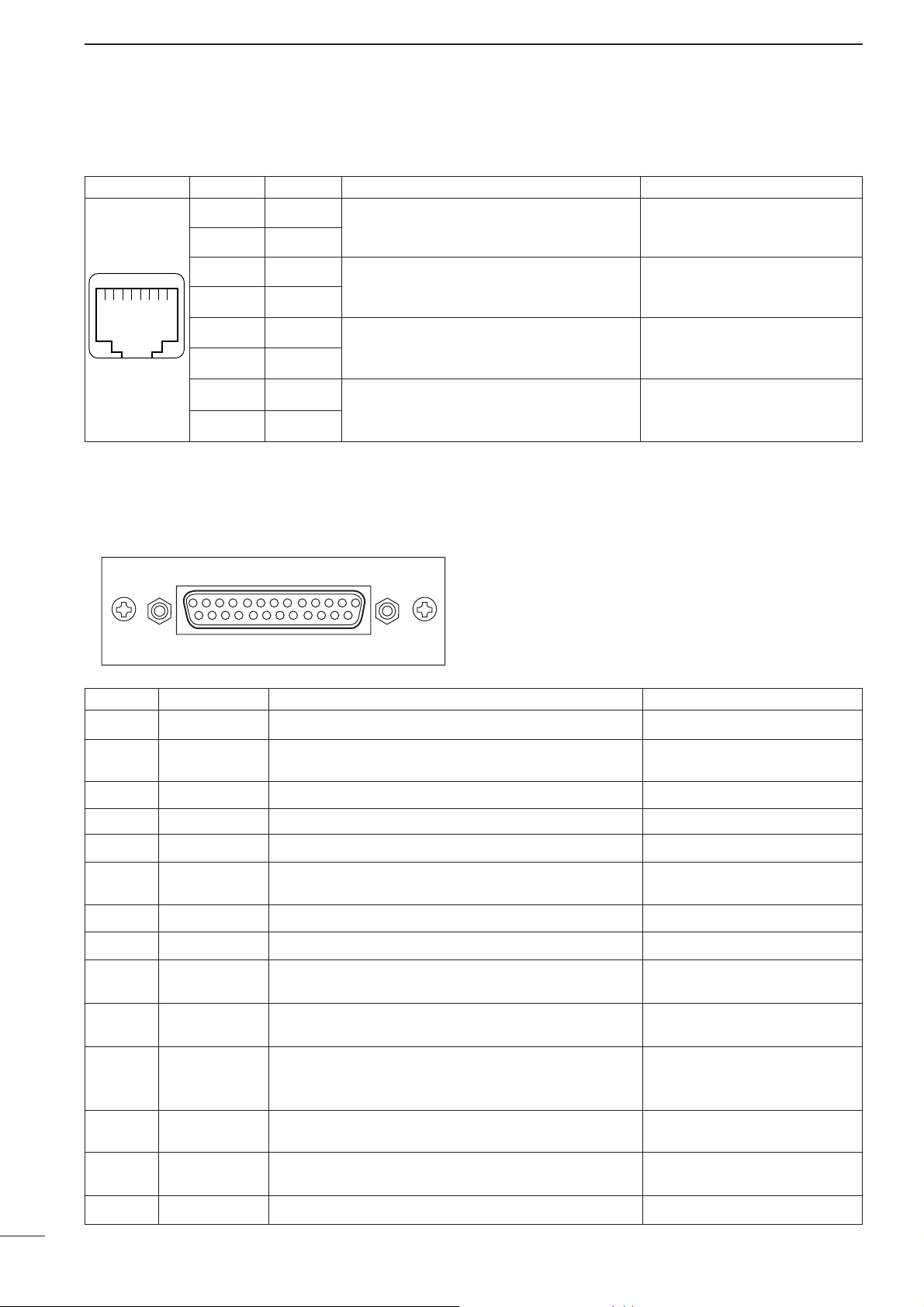
D Remote connector
Pin No. Pin Name Description Specification
1
2
3
4
5
6
7
8
–PTT
+PTT
–AFOUT
+AFOUT
–EXTMOD
+EXTMOD
–BUSY
+BUSY
Input terminals to transmit the repeater in relation to the external equipment. An opto-isolator
is provided to facilitate PTT signals.
Output terminal for AF signals from the AF detector circuit via the bandpass filter. Output level
is fixed, regardless of [AF] control.
Input terminal for the modulation circuit.
Output terminal for squelch condition
(Open/Close). An opto-isolator is provided to facilitate BUSY signals.
High voltage=PTT ON (transmits)
Hi-Z=PTT OFF
Output impedance: 600 Ω
Input impedance: 600 Ω
Open collector=BUSY OFF
0 V=BUSY ON (Squelch is opened)
q
i
D Accessory connector
Pin No. Pin Name Description Specification
1
2
3
4
5
6
7
8
9
10
11
12
13
14
BUSY OUT
COAXIAL SW
M/S IN
D1
D3
EXT RPT/BASE
EXT MONI
EXT DTCS
EXTMOD IN B
EXTMOD IN A
AF OUT
DISC OUT
+15V
TX OUT
Output terminal for busy signal.
Output terminal for coaxial switching (antenna switching)
signal.
Input terminal for master/slave signal.
Input terminal for selecting memory channel.
Input terminal for selecting memory channel.
Input terminal for repeater/base operating mode switching
signal.
Input terminal for monitor function.
Input terminal for continuous tone (CTCSS/DTCS) signal.
Input terminal for the modulation signals applied to input of
the splutter filter circuit.
Input terminal for the modulation signal applied to input of
the pre-emphasis circuit via the bandpass filter.
Output terminal for AF signals from the AF detector circuit
via the bandpass filter. Output level is fixed, regardless of
[AF] control.
Output terminal for AF signals from the AF detector circuit.
Output level is fixed, regardless of [AF] control.
Output terminal for +15V DC while in AC operation. (While in
DC operation, same as input DC.)
Output terminal for transmission state.
Open collector=OFF, 0 V=ON
Open collector=OFF
0 V=ON
+5 V pull up, Active=L
+5 V pull up, Active=L
+5 V pull up, Active=L
+5 V pull up
Active=L
+5 V pull up, Active=L
Input impedance: 100 kΩ (approx.)
Input impedance: 600 Ω (approx.)
Input impedance: 600 Ω (approx.)
Output impedance: 1 kΩ (approx.)
Output impedance: 1 kΩ (approx.)
Output current: Less than 1 A
Open collector=OFF, 0 V=ON
q!3
!4@5
Page 7

4
1
PANEL DESCRIPTION
Channel
D4 D3 D2 D1 D0
(pin 18) (pin 5) (pin 17) (pin 4) (pin16)
100000
200001
300010
400011
500100
600101
700110
800111
901000
10 0 1 0 0 1
11 0 1 0 1 0
12 0 1 0 1 1
13 0 1 1 0 0
14 0 1 1 0 1
15 0 1 1 1 0
16 0 1 1 1 1
Channel
D4 D3 D2 D1 D0
(pin 18) (pin 5) (pin 17) (pin 4) (pin16)
17 1 0 0 0 0
18 1 0 0 0 1
19 1 0 0 1 0
20 1 0 0 1 1
21 1 0 1 0 0
22 1 0 1 0 1
23 1 0 1 1 0
24 1 0 1 1 1
25 1 1 0 0 0
26 1 1 0 0 1
27 1 1 0 1 0
28 1 1 0 1 1
29 1 1 1 0 0
30 1 1 1 0 1
31 1 1 1 1 0
32 1 1 1 1 1
Accessory connector (continued)
Pin No. Pin Name Description Specification
15
16
17
18
19
20
21–24
25
M/S OUT
D0
D2
D4
EXT PTT
RSSI
AGND
DC GND
Output terminal for master/slave signal.
Input terminal for selecting memory channel.
Input terminal for selecting memory channel.
Input terminal for selecting memory channel.
Input terminal for PTT signal.
Output terminal for RSSI (Received Signal Strength Indicator) signal.
Analog ground
Ground for +15 V DC
Open collector=OFF, 0V=ON
+5 V pull up, Active=L
+5 V pull up, Active=L
+5 V pull up, Active=L
+5 V pull up, Active=L
Output impedance: 1 kΩ (approx.)
• Pin 4, pin 5, pins 16–18 select one of the 32 pre-programmed memory channels. (see table below)
[0]: Hi-Z, [1]: 0 V (D0–D4: +5 V pull up)
Page 8
2
5
INST ALLATION AND CONNECTIONS
■ Unpacking
After unpacking, immediately report any damage to the
delivering carrier or dealer. Keep the shipping cartons.
For a description and a diagram of accessory equipment included with the IC-FR3100/FR4100 series, see
‘Supplied Accessories’ on p. ii of this manual.
■ Selecting a location
Select a location for the repeater that allows adequate
air circulation, free from extreme heat, cold, or vibrations, and away from TV sets, TV antenna elements,
radios and other electromagnetic sources.
■ Antenna connection
For radio communications, the antenna is of critical importance, along with output power and sensitivity. Selecting antenna(s), such as a well-matched 50 Ω antenna, and feedline. 1.5:1 or better of Voltage Standing
Wave Ratio (VSWR) is recommended for the desired
band. Of course, the transmission line should be a
coaxial cable.
CAUTION: Protect the repeater from lightning by
using a lightning arrestor.
NOTE: There are many publications covering
proper antennas and their installation. Check with
your local dealer for more information and recommendations.
■ Duplexer
A duplexer is separately required when only one antenna is used for both transmitting and receiving. Select a duplexer according to the transmitting and receiving frequencies. Ask your Dealer for details.
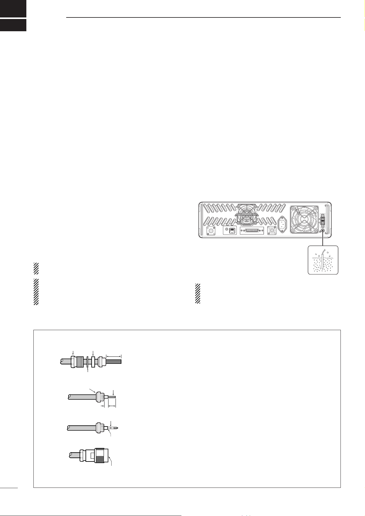
■ Grounding
To prevent electrical shock, television interference
(TVI), broadcast interference (BCI) and other problems, ground the transceiver through the [GND] terminal on the rear panel.
For best results, connect a heavy gauge wire or strap
to a long earth-sunk copper rod. Make the distance between the [GND] terminal and ground as short as possible.
RR
WARNING:
NEVER connect the [GND] termi-
nal to a gas or electric pipe, since the connection
could cause an explosion or electric shock.
TYPE-N CONNECTOR INSTALLATION EXAMPLE
30 mm ≈9⁄
8 in 10 mm ≈
3
⁄
8 in 1–2 mm ≈
1
⁄
16 in
Slide the nut, flat washer, rubber gasket and clamp over the coaxial
cable, then cut the end of the cable evenly.
Strip the cable and fold the braid back over the clamp.
Soft solder the center conductor. Install the center conductor pin and
solder it.
Carefully slide the plug body into place aligning the center conductor
pin on the cable. Tighten the nut onto the plug body.
q
w
e
r
15 mm
3 mm
6 mm
No space
Solder hole
Be sure the center conductor is
the same height as the plug body.
Clamp
Center
conductor
Washer
Nut Rubber gasket
BATTERY
GND
TX/TX•RX
EXT SP REMOTE
AC
ACC
RX
Page 9

6
2
INSTALLATION AND CONNECTIONS
TX/TX•RX
EXT SP REMOTE
ACC
RX
GND
AC
BATTERY
[TX(TX•RX) ANT] (p. 5)
[RX ANT] (p. 5)
TX•RX antenna required
for installing an internal
duplexer.
GROUND (p. 5)
[DC POWER INPUT TERMINAL] (p. 8)
12 V
battery
Supplied
DC power cable
+ red
_ black
Crimp
Solder
SM-25 DESKTOP
MICROPHONE
(optional)
MICROPHONE CONNECTOR (Front panel view)
HM-100N/TN HAND
MICROPHONE
(optional)
q +9 V DC output (Max. 10 mA)
w I/O port for PC programming
e NC
r M PTT (Input port for TX control)
t Microphone ground
y Microphone input
u Ground
i M MONI (Input port for monitor control)
q
i
CAUTION: DO NOT short pin 1 to ground as this can
damage the internal 9 V regulator. DC voltage is applied
to pin 1 for microphone operation. Take care when
using a non-Icom microphone.
Make sure the back up battery is correctly
connected. Use a cable with following
current capacity. Solder or clamp the cable
lug when connecting the power cable to the
backup battery to prevent voltage drops.
Power cable current capacity: 20 A or more
■ Required connections
Page 10

7
2
INSTALLATION AND CONNECTIONS
TX/TX•RX
EXT SP REMOTE
ACC
RX
GND
AC
BATTERY
EXTERNAL
SPEAKER
s
p
-
7
i
c
o
m
Use a 4 Ω speaker.
[REMOTE] (p. 3) ACC CONNECTOR (pgs. 3, 4)
Used for external
equipment control.
Used for external equipment control.
LINE CONNECTOR (Front panel view)
q NC (No connection)
w L1 input/output
e L2 input/output
r NC (No connection)
q
r
Telephone connector type is different for some countries.
to telephone connector
■ Advanced connections
Page 11

8
2
INSTALLATION AND CONNECTIONS
■ Power
Make sure the [POWER] switch is turned OFF when
connecting an AC power cable and a backup battery
(emergency power supply).
The IC-FR3100/FR4100 series can operate with an AC
or DC power supply. If AC power is interrupted when
operating the repeater with an AC power supply, power
is automatically provided to the [BATTERY] terminals.
NOTE: When repeatedly to turning the repeater ON
and OFF quickly, the repeater may not turn ON. In
this case turn OFF the power switch and wait for a
while, then turning power ON again.
D In AC operation
• The [DC] indicator turns OFF.
• Use the supplied AC power cable for connection to a
domestic AC outlet.
• Extension cords should not be used unless ab-
solutely necessary. Using improper extension cords
could result in fire risk.
• Usually the battery is continuously charged with a
small amount of current from an AC power supply
through the regulator circuit in the repeater. Discharging is therefore prevented even if the battery is
not used for a long time.
D In DC operation
CAUTION: Voltages greater than 16 V DC will dam-
age the repeater. Check the source voltage before
connecting the power cable.
• The [DC] indicator lights up green.
• DO NOT place the backup battery on or near the re-
peater. Lead-acid batteries should be placed at least
5 m away from the repeater. Use a heavy duty cable
to make the connection and be sure both the positive
(red) and negative (black) terminals are correctly connected.
• Connect cables to the battery in the following order.
Connect the DC power cable to the repeater first,
then the positive (red) terminal and negative (black)
terminal to the battery to prevent an electric shock.
• After the battery is connected and the [POWER]
switch is ON, the repeater continuously supplies approx. 1 A for charging the battery. If the repeater
stops functioning while connected to the battery, disconnect the battery, recharge it, then connect the battery to continue operation after the battery is charged.
During repeater transmission, approx. 15 A of battery
power is consumed.
■ Mounting the repeater
D Using the optional MB-78
An optional MB-78 19
INCH RACK MOUNT BRACKET
is
available for mounting the repeater into a 19 inch rack.
The MB-78 can install the repeater’s bottom side and
top side.
• Bottom side installation
q Remove the 2 screws (M4 × 8) from both sides of
the side panel (front-end).
w Attach the MB-78 to the bottom side of the repeater.
e Tighten the supplied screws (M4 × 8) and the 2
screws removed in step q to each side. (6 screws
in total)
r The completed bottom side installation should look
like this.
Page 12

9
2
INSTALLATION AND CONNECTIONS
• Top side installation
q Remove the screws (M4 × 8) from both sides of the
MB-78.
w Remove the handles from the bottom bar. And turn
the handles upside down, then replace the handles
right side and left side.
e Attach the handles to the bar, then tighten the
screws.
r The completed MB-78 should look like this.
t Remove the 2 screws (M4 × 8) from both sides of
the side panel (front-end).
y Attach the MB-78 to the top side of the repeater.
Then tighten the supplied screws (M4 × 8) and 2
screws removed from each side of the repeater. (6
screws in total)
u The top side installation should look like this.
i Turn the repeater upside down, and remove the 4
legs before mounting into the 19 inch rack.
Page 13

10
2
INSTALLATION AND CONNECTIONS
D Using the optional MB-77
An optional MB-77
WALL MOUNT BRACKET
is available
for mounting the repeater to a flat surface.
RWARNING: NEVER mount the repeater on the
MB-77 by yourself. At least two people are required
to mount the repeater since it weights approx. 12 kg.
•Mount the MB-77 securely with the 12 supplied
screws (M6 × 30) to a surface which is more than 50
mm thick and can support more than 20 kg (44 lb).
The unit must be mounted on a flat hard surface only.
q Attach the hinges on the right side of the repeater
as shown below.
w Tighten the 2 supplied screws (M5 × 12) for each
hinge.
e Put the MB-77 on the wall (or wherever you plan to
mount the repeater).
r Tighten the 12 supplied screws (M6 × 30) using flat
washers and spring washers.
NOTE: Mount this way so that the repeater’s front
panel will be facing dawn.
t Attach the hinges with the repeater to the MB-77
and tighten the 4 supplied screws (M5 × 10) and 2
nuts (with spring washer).
y Tighten the 3 supplied screws (M5 × 12) to the
other side.
• Accessing the internal area of the repeater when
mounted on the MB-77
q Remove the 3 screws (M5 × 12) on the left side of
the MB-77 when the repeater’s front panel is facing dawn.
w Pull the left side of the repeater.
e Remove the screws and open the bottom cover or
top cover of the repeater, then set the repeater up.
r Return the top or bottom cover of the repeater and
MB-77 to their original positions.
TOP VIEW
Wall
Page 14

3
11
OPTIONAL UNIT INSTALLATION
■ Opening the repeater’s case
Follow the case and cover opening procedures shown
here when an optional unit is installed or when adjusting the internal units, etc.
CAUTION: DISCONNECT the AC power cable
and/or DC power cable from the repeater. Otherwise, there is danger of electric shock and/or equipment damage.
q Remove 6 screws from the top of the repeater and
4 screws from the sides, then lift up the top cover.
w Turn the repeater upside down.
e Remove 6 screws from the bottom of the repeater,
and 4 screws from the sides, then lift up the bottom cover.
■ Voice scrambler unit
installation
The UT-109 (#01)/UT-110 (#01) provide high performance private communication for base operating
mode. In order to receive or send scrambled transmissions, the UT-109 (#01)/UT-110 (#01) must be installed to activate the scrambler function.
q Remove the top and bottom covers as shown
above.
w Remove 8 screws from the LOGIC shielding plate,
then remove the plate.
e Cut the pattern on the PCB at the RX AF circuit
(CP1) and TX mic circuit (CP2) on the LOGIC unit
as shown at right.
r Turn the repeater upside down, then install the
scrambler unit as shown below.
t Return the LOGIC shielding plate, top and bottom
covers to their original positions.
NOTE: Be sure to re-solder
above disconnected points,
otherwise no TX modulation or
AF output is available when you
remove the scrambler unit.
Page 15

4
12
OPERATION
■ Turning power ON
q Push [POWER] to turn the power ON.
w If the repeater is programmed for a power on pass-
word by an Icom Dealer, input the digit codes directly.
• The keys in the table below can be used for password
input.
• The repeater detects numbers in the same block as
identical. Therefore “01234” and “56789” are the same.
e When the “PASSWORD” indication does not clear
after inputting 4 digits, the input code number may
be incorrect. Turn power off and start over in this
case.
■ Receiving and transmitting
D Receiving
q Push [POWER] to turn the power ON.
w Set the audio and squelch levels.
➥ Rotate [SQUELCH] fully counterclockwise in ad-
vance.
➥ Rotate [VOLUME] to adjust the audio output level.
➥ Rotate [SQUELCH] clockwise until the noise dis-
appears.
e Push [UP] or [DN] to select the desired channel.
•When receiving a signal, BUSY indicator turns ON and
audio is emitted from the speaker.
•Further adjustment of [VOLUME] to a comfortable listen-
ing level may be necessary at this point.
D Transmitting
q Take the microphone off hook.
w Wait for the channel to become clear.
e Push and hold [PTT] to transmit, then speak into the
microphone at your normal voice level.
r Release [PTT] to receive.
IMPORTANT:
To maximize the readability of the transmitted signal:
(1) Pause briefly after pushing [PTT].
(2) Hold the microphone 2.5 to 5 cm from your mouth,
then speak into the microphone at a normal voice
level.
KEY
[DN] [UP] [MONI]
[RPT/BASE]
[REMOTE]
NUMBER
012 3 4
567 8 9
Page 16

5
13
MAINTENANCE
PROBLEM POSSIBLE CAUSE SOLUTION REF.
■ Troubleshooting
The following chart is designed to help correct problems which are not equipment malfunctions.
If you are unable to locate the cause of a problem or
solve it through the use of this chart, contact the nearest Icom Dealer or Service Center.
Power does not come on
when [POWER] switch is
ON.
No sounds from the
speaker.
Sensitivity is low and
only strong signals are
audible.
Received signal cannot
be understood.
Output power is too low.
No contact possible with
another station.
<DC operation>
• DC power cable is improperly connected.
<AC/DC common>
• Fuse is blown.
•Volume level is too low.
• The squelch is closed.
• The audio mute function is activated.
•A selective call or squelch function is activated such as 2/5 tone call or tone squelch.
• While in base operating mode, the repeater
is in the transmitting condition.
• Antenna feedline or the antenna connector
has a poor contact or has short-circuited.
• Optional voice scrambler is turned OFF.
• Scrambler code is not set correctly.
• Output power is set to Low.
• The other station is using tone squelch.
• While in base operating mode, the repeater
is set to duplex.
• Re-connect the DC power cable correctly.
• Check the cause, then replace the fuse with
a spare one. (Fuses are installed in the internal REG unit and LOGIC unit.)
• Rotate [VOLUME] clockwise to obtain a suitable listening level.
• While in base operating mode, rotate
[SQUELCH] counterclockwise to open the
squelch.
• Push [SP MUTE] to turn the audio mute
function OFF
•Turn the appropriate function OFF.
• Push [PTT] on the microphone to receive or
check the PTT line of an external unit, if connected.
• Check and re-connect (or replace if necessary), the antenna feedline or antenna connector.
•Turn the optional voice scrambler ON.
• Reset the scrambler code.
• Push channel selector to select the high
power operating channel.
•Turn the tone squelch function ON.
•Set the repeater to simplex, when the other
transceiver is set to simplex.
p. 6
p. 14
p. 12
p. 12
p. 1
–
–
p. 5
–
–
p. 1
–
–
Page 17

14
5
MAINTENANCE
■ Fuse replacement
If a fuse blows or the repeater stops functioning, try to
find the source of the problem, and replace the damaged fuse with a new, rated fuse.
RR
WARNING:
DISCONNECT the AC power
cable and/or DC power cable from the repeater.
Otherwise, there is danger of electric shock and/or
equipment damage.
D LOGIC unit
q Remove the bottom cover as shown on p. 11.
w Remove 8 screws from the LOGIC shielding plate,
then remove the plate.
e Replace the circuitry fuse as shown below.
r
Return the LOGIC shielding plate and bottom cover.
For ACC connector
D REG unit
q Remove the top cover as shown on p. 11.
w Remove the 12 screws from the REG shielding
plate, then remove the plate.
e Replace the circuitry fuse as shown below.
r Return the REG shielding plate and top cover.
For DC output line
of internal power supply
For DC output line
of internal power supply
For DC output line
of external backup battery
For DC output line
of external backup battery
Page 18

6
15
SPECIFICA TIONS AND OPTIONS
■ Specifications
Specifications are measured in accordance with EN 300 086.
DD
IC-FR3100
General
• Frequency coverage : 150.000–174.000 MHz
• Channel spacing : 12.5/25.0 kHz (Narrow/Wide)
12.5/20.0 kHz (Narrow/Middle)
• PLL channel step : 5.0, 6.25 kHz
• Frequency stability : ±1.0 kHz
• Number of channels : Max. 32 channel
• Antenna connector : Type-N ×2 (50 Ω)
• Operating temp. range : –25°C to +55°C
• Power supply voltage : 220–240 V AC (50/60 Hz)
13.2 V DC (negative ground)
• Current drain (at 13.2 V) : TX high (25 W) 10.0 A
Max. audio 2.0 A
Stand-by 1.0 A
• Dimensions : 410(W) ×110(H) ×360(D) mm
(Projections not included)
•Weight (approx.) : 12 kg
Transmitter
• RF output power : 25 W
• Modulation system : Variable reactance frequency
modulation system
• Max. frequency deviation : ±5.0 kHz (Wide),
±4.0 kHz (Middle),
±2.5 kHz (Narrow)
• Spurious emissions : Less than 0.25 µW
• Adjacent channel power : More than 70 dB
(Wide, Middle),
More than 60 dB (Narrow)
•
Intermodulation attenuation
: More than 40 dB
• Audio harmonic distortion : 3.0% typical
(at 1 kHz, 40% deviation)
• Microphone impedance : 600 Ω (8-pin modular)
Receiver
• Receive system : Double conversion
superheterodyne system
• Sensitivity (20 dB SINAD) : 0 dBµV (EMF) typical
• Intermediate frequencies : 1st; 31.65 MHz, 2nd; 455 kHz
•
Adjacent channel selectivity
: More than 70 dB
(Wide, Middle),
More than 60 dB (Narrow)
• Spurious response : More than 70 dB
• Intermodulation : More than 70 dB
• Audio output power : 2.5 W typical at 10% distortion
with a 4 Ω load
•
External speaker connector: 2-conductor 3.5 (d) mm (1⁄8") 4 Ω
DD
IC-FR4100
General
• Frequency coverage : 400.000–430.000 MHz
(Depends on version) 450.000–480.000 MHz
• Channel spacing : 12.5/25.0 kHz (Narrow/Wide)
12.5/20.0 kHz (Narrow/Middle)
• PLL channel step : 5.0, 6.25 kHz
•Frequency stability : ±1.0 kHz
• Number of channels : Max. 32 channel
• Antenna connector : Type-N ×2 (50 Ω)
• Operating temp. range : –25°C to +55°C
• Power supply voltage : 220–240 V AC (50/60 Hz)
13.2 V DC (negative ground)
• Current drain (at 13.2 V) : TX high (25 W) 12.0 A
Max. audio 2.0 A
Stand-by 1.0 A
• Dimensions : 410(W) ×110(H) ×360(D) mm
(Projections not included)
•Weight (approx.) : 12 kg
All stated specifications are subject to change without notice or obligation.
Page 19

16
6
SPECIFICATIONS AND OPTIONS
Transmitter
• RF output power : 25 W
• Modulation system : Variable reactance frequency
modulation system
• Max. frequency deviation : ±5.0 kHz (Wide),
±4.0 kHz (Middle),
±2.5 kHz (Narrow)
• Spurious emissions : Less than 0.25 µW (≤1 GHz)
Less than 1 µW (>1 GHz)
• Adjacent channel power : More than 70 dB
(Wide, Middle),
More than 60 dB (Narrow)
•
Intermodulation attenuation
: More than 40 dB
• Audio harmonic distortion : 3.0% typical
(at 1 kHz, 40% deviation)
• Microphone impedance : 600 Ω (8-pin modular)
Receiver
• Receive system : Double conversion
superheterodyne system
• Sensitivity (20 dB SINAD) : 0 dBµV (EMF) typical
• Intermediate frequencies : 1st; 70.0 MHz, 2nd; 455 kHz
•
Adjacent channel selectivity
: More than 70 dB
(Wide, Middle),
More than 60 dB (Narrow)
• Spurious response : More than 70 dB
• Intermodulation : More than 70 dB
• Audio output power : 2.5 W typical at 10% distortion
with a 4 Ω load
•
External speaker connector: 2-conductor 3.5 (d) mm (1⁄8") 4 Ω
■ Options
•MB-77 WALL MOUNT BRACKET (p. 10)
For mounting the repeater to a wall.
•MB-78 19 INCH RACK MOUNT BRACKET (pgs. 9, 10)
For mounting the repeater into a 19 inch rack.
•HM-100N HAND MICROPHONE
•HM-100TN DTMF MICROPHONE
Hand microphone with a DTMF keypad.
•SM-25 DESKTOP MICROPHONE
•UT-109 (#01) VOICE SCRAMBLER UNIT (p. 11)
Non-rolling type (max. 32 codes).
•UT-110 (#01) VOICE SCRAMBLER UNIT (p. 11)
Rolling type (max. 1020 codes).
The scrambler systems of the UT-109 and UT-110 are not
compatible with each other.
Page 20

8
17
ABOUT CE
INSTALLATION NOTES
• Compliance of base station transmitter installations with EN50385
The installation of this equipment and it’s associated
antenna should be made in such a manner as to respect the EC recommended electromagnetic (EM) field
exposure limits. (1999/519/EC)
In order not to exceed these exposure limits it is necessary to determine the ‘Compliance Boundary,’ that
means the volume within which the EM field radiated
by the transmitter/antenna installation may exceed the
1999/519/EC limits. You will then need to ensure that
members of the general public do not have access
within this area. The actual Compliance Boundary for
this repeater will be totally dependant on the antenna,
feeder, RF amplifier and other passive or active devices used in the installation.
The RF output power of this repeater is 25 watts.
The figures contained in this guide are based on the
recommended limits for the general public and are obtained by ‘worst case’ numerical analysis. For a defini-
tive evaluation of any given installation, measurements
should be made with an EM field meter and a broadband calibrated probe.
• Installation
The antenna should be installed as high as possible
for maximum efficiency and minimum EM field at
ground-level. The evaluation of radiated field should
take into account any additional RF amplifiers used,
any loss in the antenna feeder cable and the gain of
the antenna used as well as its polar radiation pattern.
If there are any objects or structures larger than half a
wavelength close to the antenna, or within the clearance distances specified, then these can cause reflections which will have an effect on the overall radiation
pattern.
For any installation you need to consider ‘height clearance’ (i.e. the height above any place where persons
may have access) and ‘front clearance’ (i.e. the distance in front of the antenna where the radiated field
may exceed the recommended limits). Normally with
an antenna installed on a reasonably high mast or
tower, there will not be any access point directly in
front but care should be exercised when there are
other buildings higher than the antenna within the
vicinity.
• Installation with a vertical type antenna at
VHF-UHF
You need to consider the distances between the antenna and any point where persons may have access.
Allowing an average height of 1.8 m for a person in the
vicinity of the antenna the clearance distances can be
evaluated as follows. For the antenna a forward gain
of 1.6 and downward gain of unity has been assumed.
Power EIRP Distance
Height Front
clearance clearance
1 watt 1.6 watts 0.32 m 2.1 m 0.4 m
10 watts 16 watts 1 m 2.8 m 1.3 m
25 watts 40 watts 1.6 m 3.4 m 2 m
100 watts 160 watts 3.2 m 5 m 4 m
1 kW 1600 watts 10 m 12 m 13 m
• Installation with a yagi or directive type antenna
Exposure distance assumes that the predominant radiation pattern is forwards and that radiation vertically
downwards is at unity gain (sidelobe suppression is
equal to main lobe gain). This is true of almost every
gain antenna today. Exposed persons are assumed to
be beneath the antenna array and have a typical
height of 1.8 m.
The figures assume the worst case emission of constant carrier.
RF power Clearance heights by frequency band
Watts 10–2 m 70 cm 23 cm
13 cm
and above
1 2.1 m 2 m 2 m 2 m
10 2.8 m 2.7 m 2.5 m 2.3 m
25 3.4 m 3.3 m 2.7 m 2.5 m
100 5 m 4.7 m 3.6 m 3.2 m
1000 12 m 11.5 m 7.3 m 6.3 m
EIRP
Forward clearance, EIRP by frequency band
Watts 10–2 m 70 cm 23 cm
13 cm
and above
100 2 m 2 m 1.1 m 0.7 m
1000 6.5 m 6 m 3.5 m 3 m
10,000 20 m 18 m 11 m 7 m
100,000 65 m 60 m 35 m 29 m
Page 21

18
8
ABOUT CE
• Typical installation example
A UHF base station transmitter is to be installed on the
roof of an office.
The transmit power is 25 watts, there is 20 m of RG213 coaxial cable and the antenna is vertically polarised dipole.
The specification of the RG-213 cable gives a loss of
1.5 dB/10 m. There will be 3 dB loss for the 20 m
length used.
The RF power at the antenna input will be 12.5 watts.
The dipole antenna has a forward gain of 0 dBd or 1.6,
giving an EIRP of 20 watts.
Referring to the table above for VHF/UHF vertical antennas, this gives a front clearance distance of approx.
1.5 m and a height clearance of 3 m.
The antenna installation needs to ensure that the lowest part of the antenna is at least 3 m above any point
where the general public may gain access and that
they cannot pass within 1.5 m in front of the antenna.
If there is no general public access to the roof in question then the antenna could be mounted on a short
stub mast. If there is such access to the roof then the
antenna could be mounted on top of a short mast of
3.2 m high. The mast position should be such that the
antenna can radiate clearly i.e. no other object or
structure is within 1.5 m (preferably more).
It should be relatively easy to fulfil all these recommendations.
If for any reason such minimum distances are impossible to guarantee then some type of access control
fence or barrier around the antenna installation should
be provided.
Should a Yagi type antenna be used then you will have
to obtain a 3 dimensional polar plot of the radiation
characteristic from the manufacturer and evaluate the
clearance distances in both vertical and horizontal
planes.
• Operating Notes
All of the above comments on RF safety assume that
the radio is transmitting continuously
in a constant car-
rier mode such as FM or RTTY etc.
The RF exposure limits recommended by the EC are
based on the mean power averaged over a 6 minute
period.
Therefore if the total transmit time during any 6 minute
period is reduced, then the installation will be even further within the recommended limits.
Similarly, not all operating modes are constant carrier.
AM type modes all have a lower mean power level.
Use of SSB or CW will reduce exposure by approximately 70% for this reason.
CE Versions of the IC-FR3100/FR4100
which display the “CE” symbol on the serial
number seal, comply with the essential requirements of the European Radio and
Telecommunication Terminal Directive
1999/5/EC.
This warning symbol indicates that this
equipment operates in non-harmonised
frequency bands and/or may be subject to
licensing conditions in the country of use.
Be sure to check that you have the correct
version of this radio or the correct programming of this radio, to comply with national licensing requirement.
Page 22

19
8
ABOUT CE
Network Compatibility Notice
Icom IC-FR3100/IC-FR4100 PSTN Interface
Scope
This Network Compatibility Notice contains national requirements for proper operation of telecommunications equipment within specific countries and is based on the ETSI document “A guide to the application of TBR21,”
EG201 121 V1.1.3 (02-2002). This notice applies to all IC-FR3100/IC-FR4100 that are marked .
This product has been tested in accordance with TBR21 for pan-European single terminal connection to the Public
Switched Telephone Network (PSTN). However, due to differences between the individual PSTNs provided in different countries, TBR21 does not, of itself, give an unconditional assurance of successful operation on every PSTN
network termination point.
In the event of problems you should contact your equipment supplier in the first instance.
Network Compatibility
In accordance with the requirements of EG201 121, no national network compatibility issues have been identified for
the following countries:
Icom is providing the following information to demonstrate telecommunications conformity for the IC-FR3100/ICFR4100 PSTN interface to the Common Technical Regulation 21 (CTR21) and EG201 121.
Using the IC-FR3100/IC-FR4100 PSTN interface connection in Germany
A filter (see annex) will be required for any analogue line that has subscriber metering pulses.
Note: These subscriber metering pulses may or may not be present on analogue lines in Germany. The subscriber
may request that metering pulses be placed on the line, or can have them removed, by calling the German network
provider. Normally metering pulses are not provided unless specifically requested by the subscriber at the time of installation.
Using the IC-FR3100/IC-FR4100 PSTN interface connection in Switzerland
A filter (see annex) will be required as all Swiss analogue lines are using subscriber metering pulses.
Annex
Suitable filters for use in conjunction with analogue lines carrying subscriber metering pulses are available from
many sources.
Currently available types include:
Tax Impulse Filter (CGTIF) from Connect Globally
Metering Pulse Filter (FIL0811602) from TeleAdapt
Billing Tone Filter (14B5109, 5123 etc) from Lexmark
0168
Austria
France
Ireland
Portugal
Belgium
Germany
Italy
Sweden
Denmark
Greece
Luxemburg
Switzerland
Finland
Iceland
Netherlands
United Kingdom
Page 23

DECLARATION
OF CONFORMITY
We Icom Inc. Japan
1-1-32, Kamiminami, Hirano-ku
Osaka 547-0003, Japan
Kind of equipment:
VHF REPEATER
This compliance is based on conformity with the following harmonised
standards, specifications or documents:
i) EN 301 489-1 v1.3.1 (September 2001)
ii) EN 301 489-5 (August 2000)
iii) EN 60950-1: 2001 (December 2001)
iv) EN 300 086-2 (March 2001)
v) EN 300 219-2 (March 2001)
vi) EN 300 113-2 (March 2001)
vii) TBR 21 (January 1998)
viii) EN50385 (2002)
Type-designation: iC-fr3100
Signature
Authorized representative name
Place and date of issue
Declare on our sole responsibility that this equipment complies with the
essential requirements of the Radio and Telecommunications Terminal
Equipment Directive, 1999/5/EC, and that any applicable Essential Test
Suite measurements have been performed.
Version (where applicable):
0168
150 174 MHz 12.5 kHz/ 25 kHz
150 174 MHz 12.5 kHz/ 20 kHz
7th July 2006
DECLARATION
OF CONFORMITY
We Icom Inc. Japan
1-1-32, Kamiminami, Hirano-ku
Osaka 547-0003, Japan
Kind of equipment:
UHF REPEATER
This compliance is based on conformity with the following harmonised
standards, specifications or documents:
i) EN 301 489-1 v1.3.1 (September 2001)
ii) EN 301 489-5 (August 2000)
iii) EN 60950-1: 2001 (December 2001)
iv) EN 300 086-2 (March 2001)
v) EN 300 219-2 (March 2001)
vi) EN 300 113-2 (March 2001)
vii) TBR 21 (January 1998)
viii) EN50385 (2002)
Type-designation: iC-fr4100
Signature
Authorized representative name
Place and date of issue
Declare on our sole responsibility that this equipment complies with the
essential requirements of the Radio and Telecommunications Terminal
Equipment Directive, 1999/5/EC, and that any applicable Essential Test
Suite measurements have been performed.
Version (where applicable):
0168
450 480 MHz 12.5 kHz/ 25 kHz
450 480 MHz 12.5 kHz/ 20 kHz
7th July 2006
20
8
ABOUT CE
DECLARATION
OF CONFORMITY
We Icom Inc. Japan
1-1-32, Kamiminami, Hirano-ku
Osaka 547-0003, Japan
Kind of equipment:
UHF REPEATER
This compliance is based on conformity with the following harmonised
standards, specifications or documents:
i) EN 301 489-1 v1.3.1 (September 2001)
ii) EN 301 489-5 (August 2000)
iii) EN 60950-1: 2001 (December 2001)
iv) EN 300 086-2 (March 2001)
v) EN 300 219-2 (March 2001)
vi) EN 300 113-2 (March 2001)
vii) TBR 21 (January 1998)
viii) EN50385 (2002)
Type-designation: iC-fr4100
Signature
Authorized representative name
Place and date of issue
7th July 2006
Declare on our sole responsibility that this equipment complies with the
essential requirements of the Radio and Telecommunications Terminal
Equipment Directive, 1999/5/EC, and that any applicable Essential Test
Suite measurements have been performed.
Version (where applicable):
0168
400 430 MHz 12.5 kHz/ 25 kHz
400 430 MHz 12.5 kHz/ 20 kHz
Page 24

1-1-32 Kamiminami, Hirano-ku, Osaka 547-0003 Japan
A-6280H-1EU-w
Printed in Japan
© 2003—2006 Icom Inc.
<Intended Country of Use>
■■ GER ■■ FRA ■■ ESP ■■ SWE
■■ AUT ■■ NED ■■ POR ■■ DEN
■■ GBR ■■ BEL ■■ ITA ■■ FIN
■■ IRL ■■ LUX ■■ GRE ■■ SUI
■■ NOR
 Loading...