

Page 1
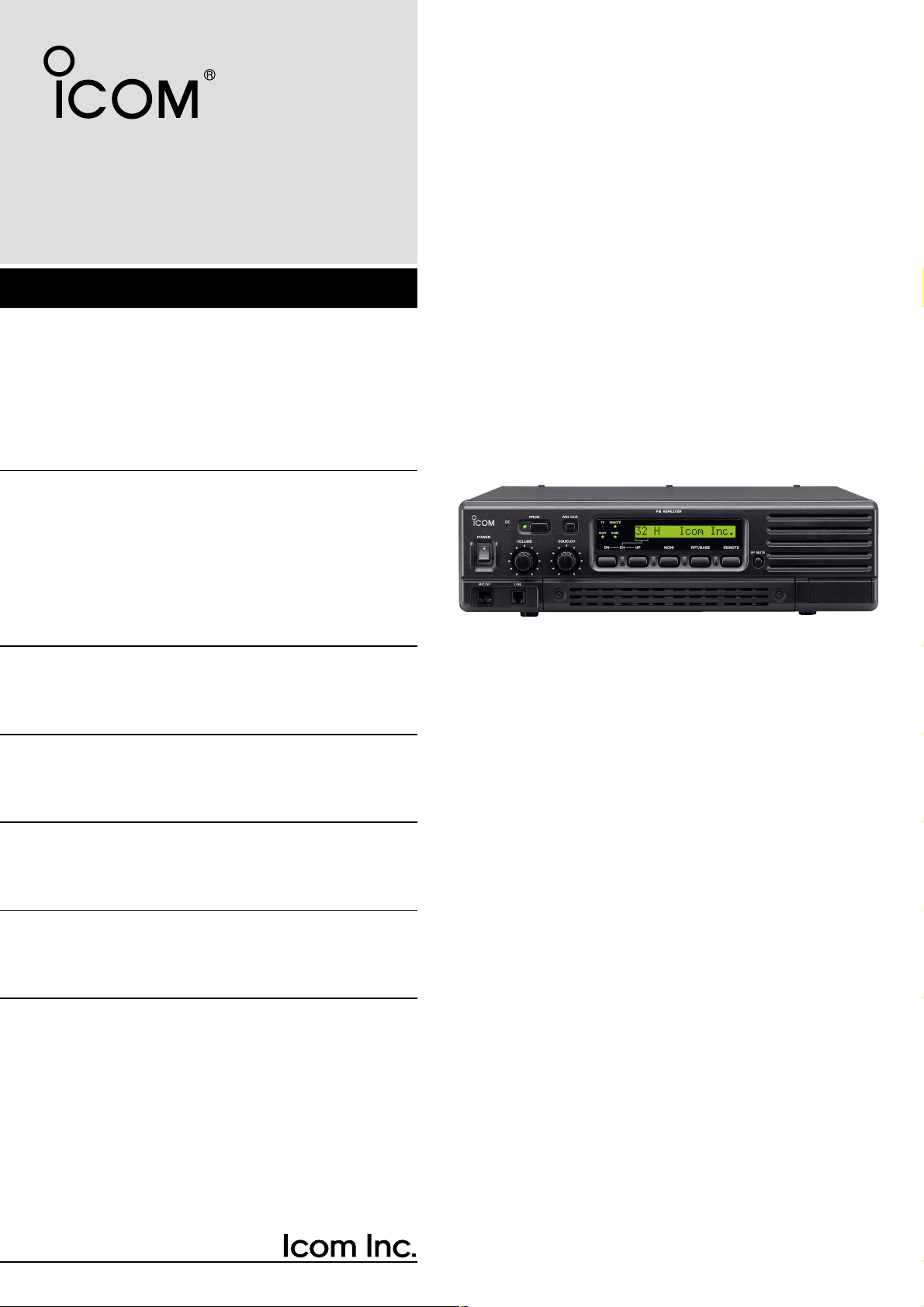
INSTRUCTION MANUAL
VHF FM REPEATER
iFR3000
UHF FM REPEATER
iFR4000
Page 2

i
IMPORTANT
READ THIS INSTRUCTION MANUAL
CAREFULLY before attempting to operate the re-
peater.
SAVE THIS INSTRUCTION MANUAL– This
manual contains important safety and operating instructions for the IC-FR3000/FR4000 series.
EXPLICIT DEFINITIONS
R WARNING HIGH VOLTAGE! NEVER at-
tach an antenna or internal antenna connector during
transmission. This may result in an electrical shock or
burn.
RWARNING HIGH VOLTAGE! NEVER install
the antenna at any place that person touch the antenna easily during transmission. This may result in an
electrical shock or burn.
R NEVER apply AC to the [BATTERY] terminals on
the repeater rear panel. This could cause a fire or
damage the repeater.
R NEVER apply more than 16 V DC, such as a 24 V
battery, to the [BATTERY] terminals on the repeater
rear panel. This could cause a fire or damage the repeater.
R NEVER let metal, wire or other objects touch any
internal part or connectors on the rear panel of the repeater. This may result in an electric shock.
R NEVER expose the repeater to rain, snow or any
liquids.
AVOID using or placing the repeater in areas with temperatures below –30°C (–22°F) or above +60°C
(+140°F). Be aware that temperatures on a vehicle’s
dashboard can exceed 80°C (+176°F), resulting in permanent damage to the repeater if left there for extended periods.
AVOID placing the repeater in excessively dusty environments or in direct sunlight.
AVOID putting anything on top of the repeater. This will
obstruct heat dissipation.
Place the repeater in a secure place to avoid inadvertent use by children.
BE CAREFUL! The heatsink will become hot when operating the repeater continuously for long periods.
BE CAREFUL! If a linear amplifier is connected, set
the repeater’s RF output power to less than the linear
amplifier’s maximum input level, otherwise, the linear
amplifier will be damaged.
Use Icom microphones only (optional). Other manufacturer’s microphones have different pin assignments,
and connection to the IC-FR3000/FR4000 series may
damage the repeater.
For U.S.A. only
CAUTION: Changes or modifications to this repeater,
not expressly approved by Icom Inc., could void your
authority to operate this repeater under FCC regulations.
CAUTION: This repeater is intended for use as a fixed
base station with the antenna located outdoors on the
rooftop or on antenna tower.
PRECAUTION
WORD
R
WARNING
CAUTION
NOTE
DEFINITION
Personal injury, fire hazard or electric
shock may occur.
Equipment damage may occur.
If disregarded, inconvenience only.
No risk of personal injury, fire or
electric shock.
Icom, Icom Inc. and the logo are registered trademarks
of Icom Incorporated (Japan) in the United states, the United
Kingdom, Germany, France, Spain, Russia and/or other countries.
Page 3

ii
For U.S.A.
This equipment complies with the Federal Communications Commission (FCC) rules and regulations governing telephone equipment and the Technical
Requirements for Connection to the Telephone Network published by the industry’s Administrative Council
for Terminal Attachments (ACTA). On the right side of
this equipment is a label that contains, among other in-
formation, a product identifier in the format
US:ICMOT03BIC-FR4000. If requested, this number
must be provided to the telephone company.
The applicable certification jack (connector) USOC-RJ11C is used for this equipment.
This device can only be connected to the Public
Switched Telephone Network (PSTN) using a telephone cord and modular plug that is compliant with the
criteria adopted by the ACTA. This equipment is designed for connection to the telephone network or
premises wiring using a compatible modular jack that
is also compliant.
The Ringer Equivalence Number (or REN) is used to
determine the number of devices that may be connected to a telephone line. Excessive RENs on a telephone line may result in the devices not ringing in
response to an incoming call. In most, but not all
areas, the sum of RENs should not exceed five (5.0).
To be certain of the number of devices that may be
connected to a line, as determined by the total RENs,
contact the local telephone company. The REN for this
product is printed on the product identifier label
CAUTION: If this equipment is deemed potentially
harmful to the telephone network, the telephone company will attempt to notify you in advance of discontinuing service. If advance notice is not practical, the
telephone company will notify you as soon as possible. If service is disconnected, you will be advised of
your right to file a complaint with the Federal Communications Commission (FCC) should you believe it necessary.
The telephone company may make changes in its facilities, equipment, operations or procedures that could
affect the operation of this equipment. Should this
occur, advance notice you be provided in order for you
to make necessary modifications to maintain uninterrupted service.
Should you experience trouble with this equipment,
please contact: ICOM America, Technical Support at
425-454-7619 for repair or warranty information. If the
equipment is causing harm to the telephone network,
the telephone company may request that you disconnect the equipment until the problem is resolved.
There are no user serviceable parts for a telephone circuit inside of this IC-FR3000 or IC-FR4000.
NOTICE: Connection to party line service is subject to
state tariffs. Contact the state public utility commission,
public service commission or corporation commission
for information.
If your home has specially wired alarm equipment connected to the telephone line, ensure the installation of
this IC-FR3000 or IC-FR4000 does not disable your
alarm equipment. If you have questions about what will
disable alarm equipment, consult your telephone company or a qualified installer.
For CANADA
NOTICE: This equipment meets the applicable Industry Canada Terminal Equipment Technical Specifications. This is confirmed by the registration number.
The abbreviation, IC, before the registration number
signifies that registration was performed based on a
Declaration of Conformity indicating that Industry
Canada technical specifications were met. It does not
imply that Industry Canada approved the equipment.
NOTICE: The Ringer Equivalence Number (REN) for
this terminal equipment is 0.3. The REN assigned to
each terminal equipment provides an indication of the
maximum number of terminals allowed to be connected to a telephone interface. The termination on an
interface may consist of any combination of devices
subject only to the requirement that the sum of the
Ringer Equivalence Numbers of all the devices does
not exceed five.
DECLARATION OF CONFORMITY
Page 4
iii
FORWARD
Thank you for purchasing this Icom product. The ICFR3000/FR4000
VHF
/
UHF FM REPEATER
is designed
and built with Icom’s state of the art technology and
craftsmanship. With proper care, this product should
provide you years of trouble-free operation.
We want to take a couple of moments of your time to
thank you for making the IC-FR3000/FR4000 your repeater of choice, and hope you agree with Icom’s philosophy of “technology first.” Many hours of research
and development went into the design of your ICFR3000/FR4000 series.
D
FEATURES
❍ 50 W continuous full duty cycle operation
This repeater looks as good as it performs. A rugged
heatsink, large cooling fans and a high performance
power module provide the repeater with a stable
50 W at full duty cycle operation.
❍
Automatic battery backup system
A built-in backup system supports automatic switching to an external power supply (13.6 V DC) if the
AC power supply fails.
❍ Multiple CTCSS & DTCS tone memories
with multiple memory channels
Up to 16 CTCSS/DTCS tones (TX/RX tones respectively) can be programmed in a channel. This feature allows you to share a channel with multiple user
groups. You can also give priority/exclusive use to a
specified group simply by programming different
tones to another memory channel. Ideal for many
different applications.
❍ Built-in 2-Tone, 5-Tone, DTMF encoder &
decoder
Multiple signaling systems are equipped as standard. These systems are fully compatible with Icom
F-series radios.
❍ Telephone interconnect capability
❍ DTMF remote control capability
You can control the repeater from a remote location
over the air or over a phone line with DTMF.
❍ Other features
- PC programmable
- Wall or 19 inch rack mount (optional MB-77/MB-78)
- Optional Voice Scrambler Unit (UT-109 #01/UT-110
#01) for base operating mode
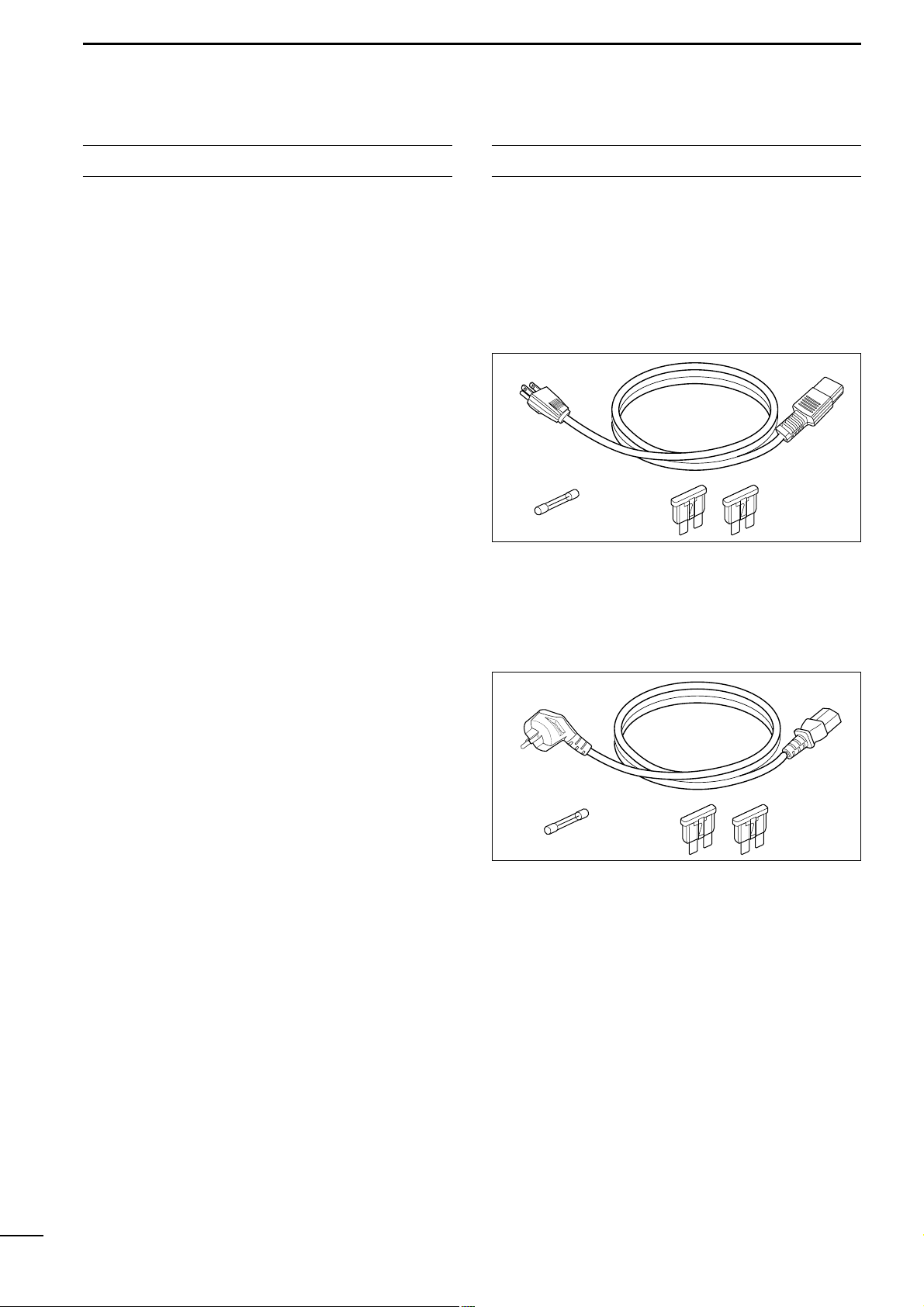
SUPPLIED ACCESSORIES
The following accessories are supplied with ICFR3000/FR4000 series
[AC120V version]
q AC power cable (OPC-510) ……………………… 1
w Spare fuses (FGB 1 A) …………………………… 1
e Spare fuses (ATC 20) ……………………………… 2
[AC220V version]
q AC power cable (OPC-492) ……………………… 1
w Spare fuses (FGB 1 A) …………………………… 1
e Spare fuses (ATC 20) ……………………………… 2
q
we
q
we
Page 5

iv
IMPORTANT ............................................................ i
EXPLICIT DEFINITIONS ......................................... i
PRECAUTION ......................................................... i
DECLARATION OF CONFORMITY ....................... ii
FORWARD ............................................................. iii
SUPPLIED ACCESSORIES .................................. iii
TABLE OF CONTENTS ......................................... iv
1 PANEL DESCRIPTION ......................... 1–4
■ Front panel .................................................... 1
■ Rear panel ..................................................... 2
D Remote connector...................................... 3
D Accessory connector.................................. 3
2 INSTALLATION AND
CONNECTIONS .................................. 5–10
■ Unpacking ..................................................... 5
■ Selecting a location ....................................... 5
■ Antenna connection ....................................... 5
■ Duplexer ........................................................ 5
■ Grounding ...................................................... 5
■ Required connections .................................... 6
■ Advanced connections .................................. 7
■ Power ............................................................ 8
D In AC operation .......................................... 8
D In DC operation.......................................... 8
■ Mounting the repeater ................................... 8
D Using the optional MB-78........................... 8
D Using the optional MB-77......................... 10
3 OPTIONAL UNIT INSTALLATION ........... 11
■ Opening the repeater’s case ....................... 11
■ Voice scrambler unit installation .................. 11
4 OPERATION ............................................ 12
■ Turning power ON ....................................... 12
■ Receiving and transmitting .......................... 12
D Receiving ................................................. 12
D Transmitting ............................................. 12
5 MAINTENANCE ................................ 13–14
■ Troubleshooting ........................................... 13
■ Fuse replacement ........................................ 14
6 SPECIFICATIONS AND OPTIONS ... 15–16
■ Specifications .............................................. 15
D IC-FR3000 ............................................... 15
D IC-FR4000 ............................................... 15
■ Options ........................................................ 16
TABLE OF CONTENTS
Page 6
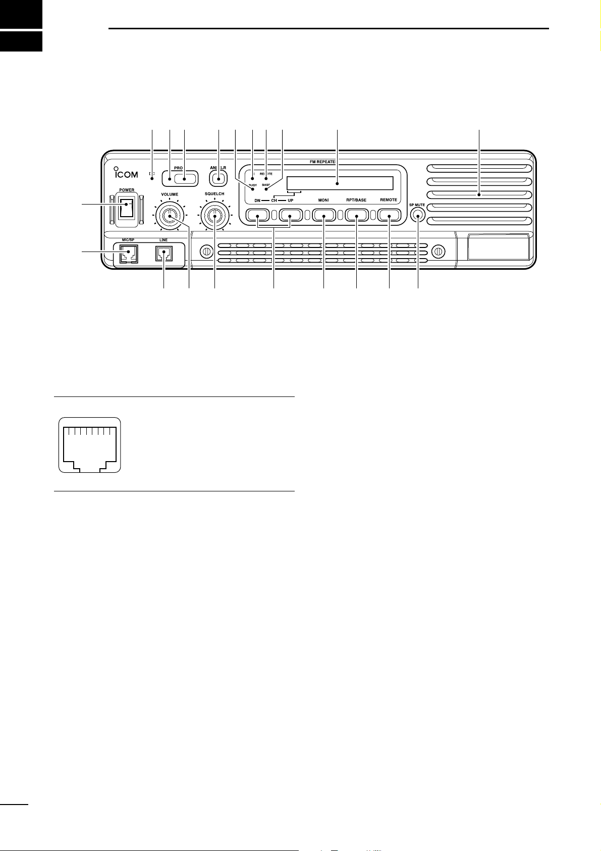
1
PANEL DESCRIPTION
1
■ Front panel
q POWER SWITCH [POWER]
Toggles to turn the repeater power ON or OFF.
w
MICROPHONE/SPEAKER CONNECTOR [MIC/SP]
This 8-pin modular jack accepts the optional microphone.
q +9 V DC output (Max. 10 mA)
w I/O port for PC programming
e NC
r M PTT (Input port for TX control)
t Microphone ground
y Microphone input
u Ground
i M MONI (Input port for monitor control)
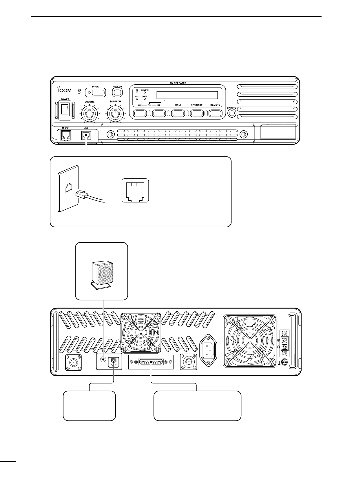
e LINE CONNECTOR [LINE]
This 4-pin modular jack accepts to connect to 2 wire
system telephone cable.
• See p. 7 for line connector information.
r VOLUME CONTROL [VOLUME] (p. 12)
Adjusts the audio output level.
t SQUELCH CONTROL [SQUELCH]
➥While in base operating mode, adjusts the
squelch threshold level. (p. 12)
➥While in repeater operating mode, this knob is not
activate.
y CHANNEL SELECT SWITCHES [DN/UP]
Push either switch to select the operating channel.
u MONITOR SWITCH [MONI]
➥Push to monitor the operating frequency.
i MODE SELECT SWITCH [RPT/BASE]
Toggles the repeater or base operating mode when
pushed.
• When setting up a repeater system using ICFR3000/FR4000 only, select a repeater operating mode.
• When using IC-FR3000/FR4000 as full (or half) duplex
transceiver or setting up a repeater system connecting
an external controller, select a base operating mode.
o REMOTE CONTROL SWITCH [REMOTE]
Toggles to activate or inactivate the remote control
operation when pushed.
!0 AF MUTE CONTROL [SP MUTE]
Mutes the audio output.
!1 INTERNAL SPEAKER
Monitors received signals.
!2 BASE OPERATING MODE INDICATOR
Lights green while in base operating mode.
!3 REMOTE CONTROL MODE INDICATOR
Lights green while in remote control operation.
!4 TRANSMIT INDICATOR
Lights red while transmitting.
!5 BUSY INDICATOR
Lights green while receiving a signal or when the
noise squelch is open.
q
i
q
w
e t y u i o !0
!2 !1!3!4!5!6!7
!8!9
r
Function display (p. 2)
Page 7
2
1
PANEL DESCRIPTION
!6 ANI CLEAR SWITCH [ANI CLR]
Push for 1 sec. to clear the received ANI ID indication on the display and returns to original indication.
NOTE: This switch is no function available for some
versions.
!7 DEALER-PROGRAMMABLE SWITCH [PROG]
Toggles the pre-programmed function ON or OFF
when pushed.
!8 PROGRAMMED FUNCTION INDICATOR
Lights green while pre-programmed function is activated.
!9 DC INDICATOR
Lights green when in DC operation.
DD
Function display
q MEMORY CHANNEL INDICATOR
Shows the selected memory channel.
w TRANSMIT POWER INDICATOR
Shows the output power level.
e AUDIBLE INDICATOR
“@” appears in an audible condition, disappears in
an inaudible condition. (When an audible condition,
audio mute is cancelled.)
r ALPHANUMERIC INDICATORS
Shows the variety text or code information.
32H H@H ICOMH INC.
q
w
e
r
■ Rear panel
q TRANSMIT ANTENNA CONNECTOR [TX/TX•RX]
➥ Connects a transmit antenna (impedance: 50 Ω)
and outputs transmit signals.
➥ When installing an optional internal duplexer
(supplied by third party), this connects the transmit receive to an antenna.
w
EXTERNAL SPEAKER CONNECTOR [EXT SP]
Accepts a 4 Ω external speaker.
e REMOTE CONNECTOR [REMOTE]
Connects to the remote controller.
• See p. 3 for remote connector information.
r ACCESSORY CONNECTOR [ACC]
Connects to the remote controller.
• See pgs. 3, 4 for accessory connector information.
t RECEIVE ANTENNA CONNECTOR [RX]
➥ Connects a receive antenna (impedance: 50 Ω)
and inputs receiving signals.
➥ When installing an internal duplexer (supplied by
third party), do not use this connector.
y AC POWER SOCKET [AC]
Connects the supplied AC power cable to a domestic AC outlet.
u GROUND TERMINAL [GND]
Ground the repeater through this terminal to prevent
electric shocks, TVI, BCI and other problems.
i DC POWER INPUT TERMINALS [BATTERY]
Connects the 12 V storage battery for the repeater
backup when the AC power is interrupted. These
terminals are also used for DC power operation.
CAUTION: NEVER short the (+) line of the DC
power cable to repeater’s chassis, when connecting
DC power cable to the [BATTERY] terminals. Otherwise, there is danger of electric shock and/or
equipment damage.
TX/TX•RX
EXT SP REMOTE
ACC
RX
GND
AC
BATTERY
q e r t y u
i
w
Page 8

3
1
PANEL DESCRIPTION
D Remote connector
Pin No. Pin Name Description Specification
1
2
3
4
5
6
7
8
–PTT
+PTT
–AFOUT
+AFOUT
–EXTMOD
+EXTMOD
–BUSY
+BUSY
Input terminals to transmit the repeater in relation to the external equipment. An opto-isolator
is provided to facilitate PTT signals.
Output terminal for AF signals from the AF detector circuit via the bandpass filter. Output level
is fixed, regardless of [AF] control.
Input terminal for the modulation circuit.
Output terminal for squelch condition
(Open/Close). An opto-isolator is provided to facilitate BUSY signals.
High voltage=PTT ON (transmits)
Hi-Z=PTT OFF
Output impedance: 600 Ω
Input impedance: 600 Ω
Open collector=BUSY OFF
0 V=BUSY ON (Squelch is opened)
q
i
D Accessory connector
Pin No. Pin Name Description Specification
1
2
3
4
5
6
7
8
9
10
11
12
13
14
BUSY OUT
COAXIAL SW
M/S IN
D1
D3
EXT RPT/BASE
EXT MONI
EXT DTCS
EXTMOD IN B
EXTMOD IN A
AF OUT
DISC OUT
+15V
TX OUT
Output terminal for busy signal.
Output terminal for coaxial switching (antenna switching)
signal.
Input terminal for master/slave signal.
Input terminal for selecting memory channel.
Input terminal for selecting memory channel.
Input terminal for repeater/base operating mode switching
signal.
Input terminal for monitor function.
Input terminal for continuous tone (CTCSS/DTCS) signal.
Input terminal for the modulation signals applied to input of
the splutter filter circuit.
Input terminal for the modulation signal applied to input of
the pre-emphasis circuit via the bandpass filter.
Output terminal for AF signals from the AF detector circuit
via the bandpass filter. Output level is fixed, regardless of
[AF] control.
Output terminal for AF signals from the AF detector circuit.
Output level is fixed, regardless of [AF] control.
Output terminal for +15V DC while in AC operation. (While in
DC operation, same as input DC.)
Output terminal for transmission state.
Open collector=OFF, 0 V=ON
Open collector=OFF
0 V=ON
+5 V pull up, Active=L
+5 V pull up, Active=L
+5 V pull up, Active=L
+5 V pull up
Active=L
+5 V pull up, Active=L
Input impedance: 100 kΩ (approx.)
Input impedance: 600 Ω (approx.)
Input impedance: 600 Ω (approx.)
Output impedance: 1 kΩ (approx.)
Output impedance: 1 kΩ (approx.)
Output current: Less than 1 A
Open collector=OFF, 0 V=ON
q!3
!4@5
Page 9

4
1
PANEL DESCRIPTION
Channel
D4 D3 D2 D1 D0
(pin 18) (pin 5) (pin 17) (pin 4) (pin16)
1 00000
2 00001
3 00010
4 00011
5 00100
6 00101
7 00110
8 00111
9 01000
10 0 1 0 0 1
11 0 1 0 1 0
12 0 1 0 1 1
13 0 1 1 0 0
14 0 1 1 0 1
15 0 1 1 1 0
16 0 1 1 1 1
Channel
D4 D3 D2 D1 D0
(pin 18) (pin 5) (pin 17) (pin 4) (pin16)
17 1 0 0 0 0
18 1 0 0 0 1
19 1 0 0 1 0
20 1 0 0 1 1
21 1 0 1 0 0
22 1 0 1 0 1
23 1 0 1 1 0
24 1 0 1 1 1
25 1 1 0 0 0
26 1 1 0 0 1
27 1 1 0 1 0
28 1 1 0 1 1
29 1 1 1 0 0
30 1 1 1 0 1
31 1 1 1 1 0
32 1 1 1 1 1
Accessory connector (continued)
Pin No. Pin Name Description Specification
15
16
17
18
19
20
21–24
25
M/S OUT
D0
D2
D4
EXT PTT
RSSI
AGND
DC GND
Output terminal for master/slave signal.
Input terminal for selecting memory channel.
Input terminal for selecting memory channel.
Input terminal for selecting memory channel.
Input terminal for PTT signal.
Output terminal for RSSI (Received Signal Strength Indicator) signal.
Analog ground
Ground for +15 V DC
Open collector=OFF, 0V=ON
+5 V pull up, Active=L
+5 V pull up, Active=L
+5 V pull up, Active=L
+5 V pull up, Active=L
Output impedance: 1 kΩ (approx.)
• Pin 4, pin 5, pins 16–18 select one of the 32 pre-programmed memory channels. (see table below)
[0]: Hi-Z, [1]: 0 V (D0–D4: +5 V pull up)
Page 10
2
5
INSTALLATION AND CONNECTIONS
■ Unpacking
After unpacking, immediately report any damage to the
delivering carrier or dealer. Keep the shipping cartons.
For a description and a diagram of accessory equipment included with the IC-FR3000/FR4000 series, see
‘Supplied accessories’ on p. iii of this manual.
■ Selecting a location
Select a location for the repeater that allows adequate
air circulation, free from extreme heat, cold, or vibrations, and away from TV sets, TV antenna elements,
radios and other electromagnetic sources.
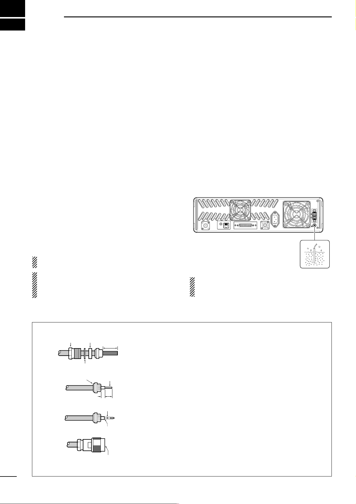
■ Antenna connection
For radio communications, the antenna is of critical importance, along with output power and sensitivity. Select antenna(s), such as a well-matched 50 Ω antenna,
and feedline. 1.5:1 or better of Voltage Standing Wave
Ratio (VSWR) is recommended for desired band. Of
course, the transmission line should be a coaxial
cable.
CAUTION: Protect repeater from lightning by using
a lightning arrestor.
NOTE: There are many publications covering
proper antennas and their installation. Check with
your local dealer for more information and recommendations.
■ Duplexer
A duplexer is separately required when only one antenna is used for both transmitting and receiving. Select a duplexer according to the transmitting and receiving frequencies. Ask your Dealer for details.
■ Grounding
To prevent electrical shock, television interference
(TVI), broadcast interference (BCI) and other problems, ground the transceiver through the [GND] terminal on the rear panel.
For best results, connect a heavy gauge wire or strap
to a long earth-sunk copper rod. Make the distance between the [GND] terminal and ground as short as possible.
RR
WARNING: NEVER connect the [GND] termi-
nal to a gas or electric pipe, since the connection
could cause an explosion or electric shock.
TX/TX•RX
EXT SP REMOTE
ACC
RX
GND
AC
BATTERY
TYPE-N CONNECTOR INSTALLATION EXAMPLE
30 mm ≈9⁄8 in 10 mm ≈3⁄8 in 1–2 mm ≈1⁄16 in
q
Nut Rubber gasket
15 mm
Slide the nut, flat washer, rubber gasket and clamp over the coaxial
cable, then cut the end of the cable evenly.
Washer
3 mm
Center
conductor
6 mm
Solder hole
Strip the cable and fold the braid back over the clamp.
Soft solder the center conductor. Install the center conductor pin and
w
e
Clamp
solder it.
No space
Carefully slide the plug body into place aligning the center conductor
pin on the cable. Tighten the nut onto the plug body.
r
Be sure the center conductor is
the same height as the plug body.
Page 11

6
2
INSTALLATION AND CONNECTIONS
TX/TX•RX
EXT SP REMOTE
ACC
RX
GND
AC
BATTERY
[TX(TX•RX) ANT] (p. 5)
[RX ANT] (p. 5)
TX•RX antenna required
for installing an internal
duplexer.
GROUND (p. 5)
[DC POWER INPUT TERMINAL] (p. 8)
12 V
battery
Supplied
DC power cable
+ red
_ black
Crimp
Solder
SM-25 DESKTOP
MICROPHONE
(optional)
MICROPHONE CONNECTOR (Front panel view)
HM-100N/TN HAND
MICROPHONE
(optional)
q +9 V DC output (Max. 10 mA)
w I/O port for PC programming
e NC
r M PTT (Input port for TX control)
t Microphone ground
y Microphone input
u Ground
i M MONI (Input port for monitor control)
q
i
CAUTION: DO NOT short pin 1 to ground as this can
damage the internal 9 V regulator. DC voltage is applied
to pin 1 for microphone operation. Take care when
using a non-Icom microphone.
Make sure the back up battery is correctly
connected. Use a cable with following
current capacity. Solder or clamp the cable
lug when connecting the power cable to the
backup battery to prevent voltage drops.
Power cable current capacity: 25 A or more
■ Required connections
Page 12
7
2
INSTALLATION AND CONNECTIONS
TX/TX•RX
EXT SP REMOTE
ACC
RX
GND
AC
BATTERY
EXTERNAL
SPEAKER
s
p
-
7
i
c
o
m
Use a 4 Ω speaker.
[REMOTE] (p. 3) ACC CONNECTOR (pgs. 3, 4)
Used for external
equipment control.
Used for external equipment control.
LINE CONNECTOR (Front panel view)
q NC (No connection)
w L1 input/output
e L2 input/output
r NC (No connection)
q
r
TEL
* This illustration is example only.
Telephone connector type is different for some countries.
■ Advanced connections
Page 13
8
2
INSTALLATION AND CONNECTIONS
■ Power
Make sure the [POWER] switch is turned OFF when
connecting an AC power cable and a backup battery
(emergency power supply).
The IC-FR3000/FR4000 series can operate with an AC
or DC power supply. If AC power is interrupted when
operating the repeater with an AC power supply, power
is automatically provided to the [BATTERY] terminals.
NOTE: When repeat to turn the repeater ON and
OFF quickly, the repeater may not turn ON. In this
case turn OFF the power switch and wait for a
while, then turning power ON again.
D In AC operation
• The [DC] indicator turns OFF.
• Use the supplied AC power cable for connection to a
domestic AC outlet.
• Extension cords should not be used unless ab-
solutely necessary. Using improper extension cords
could result in fire risk.
• Usually the battery is continuously charged with a
small amount of current from an AC power supply
through the regulator circuit in the repeater. Discharging is therefore prevented even if the battery is
not used for a long time.
D In DC operation
CAUTION: Voltages greater than 16 V DC will dam-
age the repeater. Check the source voltage before
connecting the power cable.
• The [DC] indicator lights up green.
• DO NOT place the backup battery on or near the re-
peater. Lead-acid batteries should be placed at least
5 m (16.4 ft.) away from the repeater. Use a heavy
duty cable to make the connection and be sure both
the positive (red) and negative (black) terminals are
correctly connected.
• When connecting to the battery, keep in order to con-
nect the DC power cable to the repeater first, then
the positive (red) terminal and negative (black) terminal to the battery to prevent an electric shock.
• After the battery is connected and the [POWER]
switch is ON, the repeater continuously supplies approx. 1 A for charging the battery. If the repeater
stops functioning while connected to the battery, disconnect the battery, recharge it, then connect the battery to continue operation after the battery is charged.
During repeater transmission, approx. 17 A of battery
power is consumed.
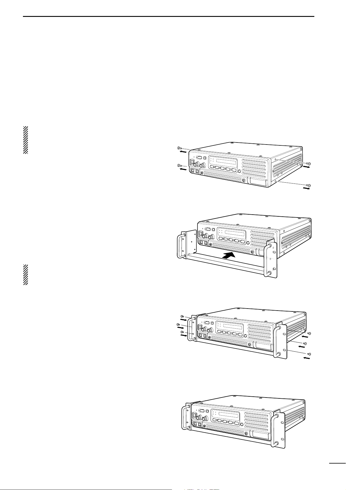
■ Mounting the repeater
D Using the optional MB-78
An optional MB-78 19
INCH RACK MOUNT BRACKET
is
available for mounting the repeater into a 19 inch rack.
The MB-78 can install the repeater’s bottom side and
top side.
• Bottom side installation
q Remove the 2 screws (M4 × 8) from both side of the
side panel (front-end).
w Attach the MB-78 to the bottom side of the repeater.
e Tighten the 1 supplied screws (M4 × 8) and 2 re-
moved screws to each side. (6 screws at total)
r The completed bottom side installation should look
like below.
Page 14

9
2
INSTALLATION AND CONNECTIONS
• Top side installation
q Remove the 1 screw (M4 × 8) from both side of the
MB-78.
w Remove the handles from bottom bar. And turn the
handles upside down, then replace the handles
right side and left side.
e Attach the handles to the bar, then tighten the
screws.
r The completed MB-78 should look like below.
t Remove the 2 screws (M4 × 8) from both side of
the side panel (front-end).
y Attach the MB-78 to the top side of the repeater.
Then tighten the 1 supplied screws (M4 × 8) and 2
removed screws to each side. (6 screws at total)
u The top side installation should look like below.
i Turn the repeater upside down, then removing the
4 legs for mounting the 19 inch rack.
Page 15

10
2
INSTALLATION AND CONNECTIONS
D Using the optional MB-77
An optional MB-77
WALL MOUNT BRACKET
is available
for mounting the repeater to a flat surface.
RWARNING: NEVER mount the repeater on the
MB-77 by yourself. At least two people are required
to mount the repeater since it weights approx. 12
kg (26 lb).
•Mount the MB-77 securely with the 12 supplied
screws (M6 × 30) to a surface which is more than 50
mm thick and can support more than 20 kg. The unit
must be mounted on a flat hard surface only.
q Attach the hinges at right side of the repeater as
shown below.
w Tighten the 2 supplied screws (M5 × 12) for each.
e Put the MB-77 on the wall (or wherever you plan to
mount the repeater).
r Tighten the 12 supplied screws (M6 × 30) using flat
washers and spring washers.
NOTE: Put this way to repeater’s front panel will be
bottom side.
t Attach the hinges with repeater to MB-77 and
tighten the 4 supplied screws (M5 × 10) and 2 nuts
(with spring washer).
y Tighten the 3 supplied screws (M5 × 12) to other
side.
• For setting up the repeater with MB-77
q Remove the 3 screws (M5 × 12) at left side of the
MB-77 when repeater’s front panel is bottom side.
w Pull the left side of the repeater.
e Remove the screws and open the bottom cover or
top cover of the repeater, then set the repeater up.
r Return the top or bottom cover of the repeater and
MB-77 to their original positions.
TOP VIEW
Wall
Page 16

3
11
OPTIONAL UNIT INSTALLATION
■ Opening the repeater’s case
Follow the case and cover opening procedures shown
here when an optional unit is installed or adjust the internal units, etc.
CAUTION: DISCONNECT the AC power cable
and/or DC power cable from the repeater. Otherwise, there is danger of electric shock and/or equipment damage.
q Remove 6 screws from the top of the repeater and
4 screws from the sides, then lift up the top cover.
w Turn the repeater upside down.
e Remove 6 screws from the bottom of the repeater,
and 4 screws from the sides, then lift up the bottom cover.
■ Voice scrambler unit
installation
The UT-109 (#01)/UT-110 (#01) provides high performance private communication for base operating
mode. In order to receive or send scrambled transmissions, the UT-109 (#01)/UT-110 (#01) must be installed and to activate the scrambler function.
q Remove the top and bottom covers as shown
above.
w Remove 8 screws from the LOGIC shielding plate,
then remove the plate.
e Cut the pattern on the PCB at the RX AF circuit
(CP1) and TX mic circuit (CP2) on the LOGIC unit
as shown at right.
r Turn the repeater upside down, then install the
scrambler unit as shown below.
t Return the LOGIC shielding plate, top and bottom
covers to their original positions.
NOTE: Be sure to re-solder
above disconnected points,
otherwise no TX modulation or
AF output is available when
you remove the scrambler unit.
Page 17

4
12
OPERATION
■ Turning power ON
q Push [POWER] to turn power ON.
w If the repeater is programmed for a power on pass-
word by an Icom Dealer, input digit codes directly.
• The keys in the table below can be used for password
input.
• The repeater detects numbers in the same block as
identical. Therefore “01234” and “56789” are the same.
e When the “PASSWORD” indication does not clear
after inputting 4 digits, the input code number may
be incorrect. Turn power off and start over in this
case.
■ Receiving and transmitting
D Receiving
q Push [POWER] to turn power ON.
w Set the audio and squelch levels.
➥ Rotate [SQUELCH] fully counterclockwise in ad-
vance.
➥ Rotate [VOLUME] to adjust the audio output level.
➥ Rotate [SQUELCH] clockwise until the noise dis-
appears.
e Push [UP] or [DN] to select the desired channel.
•When receiving a signal, BUSY indicator turns ON and
audio is emitted from the speaker.
•Further adjustment of [VOLUME] to a comfortable listen-
ing level may be necessary at this point.
D Transmitting
q Take the microphone off hook.
w Wait for the channel to become clear.
e Push and hold [PTT] to transmit, then speak into the
microphone at your normal voice level.
r Release [PTT] to receive.
IMPORTANT:
To maximize the readability of the transmitted signal:
(1) Pause briefly after pushing [PTT].
(2) Hold the microphone 1 to 2 inch (2.5 to 5 cm) from
your mouth, then speak into the microphone at a
normal voice level.
KEY
[DN] [UP] [MONI]
[RPT/BASE]
[REMOTE]
NUMBER
012 3 4
567 8 9
Page 18

5
13
MAINTENANCE
PROBLEM POSSIBLE CAUSE SOLUTION REF.
■ Troubleshooting
The following chart is designed to help correct problems which are not equipment malfunctions.
If you are unable to locate the cause of a problem or
solve it through the use of this chart, contact the nearest Icom Dealer or Service Center.
Power does not come on
when [POWER] switch is
ON.
No sounds from the
speaker.
Sensitivity is low and
only strong signals are
audible.
Received signal cannot
be understood.
Output power is too low.
No contact possible with
another station.
<DC operation>
• DC power cable is improperly connected.
<AC/DC common>
• Fuse is blown.
• Volume level is too low.
• The squelch is closed.
• The audio mute function is activated.
•A selective call or squelch function is activated such as 2/5 tone call or tone squelch.
• While in base operating mode, the repeater
is in the transmitting condition.
• Antenna feedline or the antenna connector
has a poor contact or short-circuited.
• Optional voice scrambler is turned OFF.
• Scrambler code is not set correctly.
• Output power is set to Low.
• The other station is using tone squelch.
• While in base operating mode, the repeater
is set to duplex.
• Re-connect the DC power cable correctly.
• Check the cause, then replace the fuse with
a spare one. (Fuses are installed in the internal REG unit and LOGIC unit.)
• Rotate [VOLUME] clockwise to obtain a suitable listening level.
•While in base operating mode, rotate
[SQUELCH] to counterclockwise to open the
squelch.
• Push [SP MUTE] to the audio mute function
OFF
• Turn the appropriate function OFF.
• Push [PTT] on the microphone to receive or
check the PTT line of an external unit, if connected.
•Check and re-connect (or replace if necessary), the antenna feedline or antenna connector.
• Turn the optional voice scrambler ON.
• Reset the scrambler code.
•Push channel selector to select the high
power operating channel.
• Turn the tone squelch function ON.
•Set the repeater to simplex, when other
transceiver is set to simplex.
p. 6
p. 14
p. 12
p. 12
p. 1
–
–
p. 5
–
–
p. 1
–
–
Page 19

14
5
MAINTENANCE
■ Fuse replacement
If a fuse blows or the repeater stops functioning, try to
find the source of the problem, and replace the damaged fuse with a new, rated fuse.
RR
WARNING: DISCONNECT the AC power
cable and/or DC power cable from the repeater.
Otherwise, there is danger of electric shock and/or
equipment damage.
D LOGIC unit
q Remove the bottom cover as shown on p. 11.
w Remove 8 screws from the LOGIC shielding plate,
then remove the plate.
e Replace the circuitry fuse as shown below.
r
Return the LOGIC shielding plate and bottom cover.
For ACC connector
D REG unit
q Remove the top cover as shown on p. 11.
w Remove the 12 screws from the REG shielding
plate, then remove the plate.
e Replace the circuitry fuse as shown below.
r Return the REG shielding plate and top cover.
For DC output line
of internal power supply
For DC output line
of internal power supply
For DC output line
of external backup battery
For DC output line
of external backup battery
Page 20

6
15
SPECIFICATIONS AND OPTIONS
■ Specifications
Specifications are measured in accordance with EIA/TIA-603.
DD
IC-FR3000
General
• Frequency coverage : 150.000–174.000 MHz*
148.000–172.000 MHz*
* Depends on version
• Channel specing : 12.5/25.0 kHz (Narrow/Wide)
• PLL channel step : 5.0, 6.25 kHz (2.5 kHz repeater
operation only)
• Frequency stability : ±2.5 ppm
• Number of channels : Max. 32 channel
• Antenna connector : Type-N× 2 (50 Ω)
• Operating temp. range : –30°C to +60°C
(–22°F to +140°F)
• Power supply voltage : 100–120 V AC (50/60 Hz)*
220–240 V AC (50/60 Hz)*
13.6 V DC (negative ground)
* Depends on version
• Current drain (at 13.6 V) : TX high (50 W) 15.0 A
Max. audio 2.0 A
Stand-by 1.0 A
• Dimensions : 410(W) × 110(H) × 360(D) mm
(Projections not included) 16
1
⁄
3(W) × 4
1
⁄
3(H) × 14
1
⁄
4(D) in
• Weight (approx.) : 12 kg; 26 lb 7 oz
Transmitter
• RF output power : 50 W
• Modulation system : Variable reactance frequency
modulation system
• Max. frequency deviation : ±5.0 kHz (Wide),
±2.5 kHz (Narrow)
• Spurious emissions : 70 dB
• Adjacent channel power : More than 70 dB (Wide),
More than 60 dB (Narrow)
• Audio harmonic distortion : 3.0% typical
(at 1 kHz, 40% deviation)
• Hum and noise : More than 40 dB (Wide),
More than 34 dB (Narrow)
• Microphone impedance : 600 Ω (8-pin modular)
Receiver
• Receive system : Double conversion
superheterodyne system
• Sensitivity (12 dB SINAD) : 0.25 µV typical
• Intermediate frequencies : 1st; 31.65 MHz, 2nd; 455 kHz
•
Adjacent channel selectivity
: More than 70 dB (Wide),
More than 60 dB (Narrow)
• Spurious response : More than 70 dB
• Intermodulation : More than 70 dB
• Hum and noise : More than 40 dB (Wide),
More than 34 dB (Narrow)
• Audio output power : 2.5 W typical at 10% distortion
with a 4 Ω load
•
External speaker connector:2-conductor 3.5 (d) mm (
1
⁄
8") 4 Ω
DD
IC-FR4000
General
• Frequency coverage : 400.000–430.000 MHz*
430.000–450.000 MHz*
450.000–480.000 MHz*
* Depends on version
• Channel specing : 12.5/25.0 kHz (Narrow/Wide)
• PLL channel step : 5.0, 6.25 kHz
• Frequency stability : ±1.5 ppm*/±2.5 ppm*
* Depends on version
• Number of channels : Max. 32 channel
• Antenna connector : Type-N× 2 (50 Ω)
• Operating temp. range : –30°C to +60°C
(–22°F to +140°F)
• Power supply voltage : 100–120 V AC (50/60 Hz)*
220–240 V AC (50/60 Hz)*
13.6 V DC (negative ground)
* Depends on version
• Current drain (at 13.6 V) : TX high (50 W) 20.0 A
Max. audio 2.0 A
Stand-by 1.0 A
• Dimensions : 410(W) × 110(H) × 360(D) mm
(Projections not included) 16
1
⁄
3(W) × 4
1
⁄
3(H) × 14
1
⁄
4(D) in
• Weight (approx.) : 12 kg; 26 lb 7 oz
All stated specifications are subject to change without notice or obligation.
Page 21

16
6
SPECIFICATION AND OPTIONS
Transmitter
• RF output power : 50 W
• Modulation system : Variable reactance frequency
modulation system
• Max. frequency deviation : ±5.0 kHz (Wide),
±2.5 kHz (Narrow)
• Spurious emissions : 70 dB
• Adjacent channel power : More than 70 dB (Wide),
More than 60 dB (Narrow)
• Audio harmonic distortion : 3.0% typical
(at 1 kHz, 40% deviation)
• Hum and noise : More than 40 dB (Wide),
More than 34 dB (Narrow)
• Microphone impedance : 600 Ω (8-pin modular)
Receiver
• Receive system : Double conversion
superheterodyne system
• Sensitivity (12 dB SINAD) : 0.25 µV typical
• Intermediate frequencies : 1st; 70.0 MHz, 2nd; 455 kHz
•
Adjacent channel selectivity
: More than 70 dB (Wide),
More than 60 dB (Narrow)
• Spurious response : More than 70 dB
• Intermodulation : More than 70 dB
• Hum and noise : More than 40 dB (Wide),
More than 34 dB (Narrow)
• Audio output power : 2.5 W typical at 10% distortion
with a 4 Ω load
•
External speaker connector:2-conductor 3.5 (d) mm (
1
⁄
8") 4 Ω
■ Options
• MB-77 WALL MOUNT BRACKET (p. 10)
For mounting the repeater to a wall.
• MB-78 19 INCH RACK MOUNT BRACKET (pgs. 9, 10)
For mounting the repeater into a 19 inch rack.
• HM-100N HAND MICROPHONE
• HM-100TN DTMF MICROPHONE
Hand microphone with a DTMF keypad.
• SM-25 DESKTOP MICROPHONE
• UT-109 (#01) VOICE SCRAMBLER UNIT (p. 11)
Non-rolling type (max. 32 codes).
• UT-110 (#01) VOICE SCRAMBLER UNIT (p. 11)
Rolling type (max. 1020 codes).
The scrambler systems of the UT-109 and UT-110 are not
compatible with each other.
Page 22

17
MEMO
Page 23

18
MEMO
Page 24

Count on us!
1-1-32 Kamiminami, Hirano-ku, Osaka 547-0003 Japan
A-6228H-1EX-w
Printed in Japan
© 2003 Icom Inc.
 Loading...