

Page 1
CHANGING THE IC-FC5000E IP ADDRESS
Internet Explorer 10.0 or later is required to
correctly open the Setting screen of the controller.
The following instructions are based on using
Internet Explorer 11.0.
JavaScript must be installed to open the side menu
and help window of the Setting screen.
1. Accessing the Setting screen
You have to wait to launch the web browser until the
controller system software startup is completed.
It typically takes 1 to 2 minutes for the controller to
startup the software.
1. Connect a CAT-5 straight cable between the
controller’s [LAN] connector and a PC. (p. 3)
2. Before accessing the Setting screen, change the
IP address of the PC to 192.168.0.XXX* (Subnet
mask should be 255.255.255.0) in the Control
Panel.
* Replace XXX with any number between 1 and 254
(except 100).
L Refer to the Operating System’s manual for
details.
3. Open your web browser.
4. Enter “http://192.168.0.100/control” (default IP
address of the IC-FC5000E)
and then push [Enter].
• The Login Authentication screen is displayed.
Enter
5. Enter “admin” (user name) and “admin” (default
password) in their respective input field, and then
click <Log In>.
• The Opening screen is displayed.
w Click
into the address bar,
q Enter
Upper: User name
Lower: Password
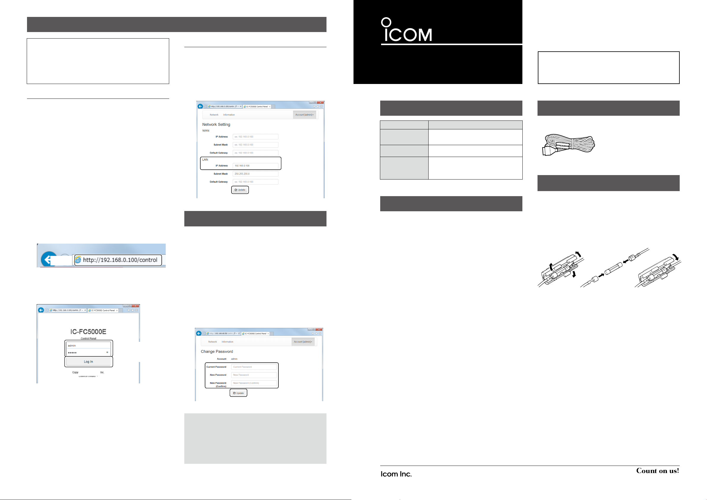
2. Changing the IP address
1. Click [Network].
• The “Network Setting” screen is displayed.
2. Enter the static IP address into the [IP Address]
field of LAN.
LSubnet mask should be “255.255.255.0.”
3. Click <Update>.
• The changed IP address is saved.
q Enter
w Click
CHANGING THE PASSWORD
You can change the password.
1. Access the Setting screen as described to the left.
2. Click [Account [admin]
Password].
• The “Change Password” screen is displayed.
3. Enter your current password into the [Current
Password] field.
4. Enter the new password into the [New Password]
field.
5. Enter the same password that you entered in step
4 into the [New Password (Confirm)] field.
6. Click <Update>.
• The new password is saved.
√], and then click [Change
q Enter
w Click
INSTRUCTIONS
IDAS TRUNKING CONTROLLER
Iç-FC5000E
EXPLICIT DEFINITIONS
WORD DEFINITION
RWARNING!
CAUTION Equipment damage may occur.
NOTE
RWARNING! NEVER apply AC to the DC power
receptacle on the controller rear panel. This could
cause a re or damage the controller.
RWARNING! NEVER apply more than 13.2 V DC to
the DC power receptacle on the controller rear panel.
This could cause a re or damage the controller.
RWARNING! NEVER reverse the DC power cable
polarity when connecting to a power source. This
could cause a re or damage the controller.
CAUTION: NEVER let metal, wire or other objects
touch any internal part or make incorrect contact with
the connectors on the rear panel of the controller. This
may result in an electric shock.
CAUTION: NEVER expose the controller to rain,
snow or any liquids.
DO NOT operate or place the controller in areas with
temperatures below 0°C or above +40°C.
DO NOT place the controller in excessively dusty
environments or in direct sunlight.
DO NOT put anything on top of the controller. This will
obstruct heat dissipation.
Place the controller in a secure place to avoid
inadvertent use by unauthorized persons.
Personal injury, re hazard or
electric shock may occur.
If disregarded, inconvenience
only. No risk of personal injury, re
or electric shock.
PRECAUTIONS
Thank you for choosing the IC-FC5000E idas
trunking controller.
READ ALL INSTRUCTIONS carefully and
completely before using the controller.
SUPPLIED ACCESSORY
DC power cable
FUSE REPLACEMENT
Fuses are installed in the supplied DC power cable. If
a fuse blows or the controller stops functioning, track
down the source of the problem if possible, and then
replace the damaged fuse with a new rated one.
Fuse rating: 3 A
USE only a 3 A fuse.
NOTE: You can reset all set contents of the
controller, including the IP address and password
that you have changed as described above, to the
factory defaults.
z Hold down [INT RESET] on the controller’s rear
panel for 5 seconds.
• All settings are reset to their default values.
– 4 –
1-1-32 Kamiminami, Hirano-ku, Osaka 547-0003, Japan
Icom, Icom Inc. and the Icom logo are registered trademarks of Icom
Incorporated (Japan) in Japan, the United States, the United Kingdom,
Germany, France, Spain, Russia, Australia, New Zealand, and/or other
countries.
IDAS and the IDAS logo are trademarks of Icom Incorporated.
All other products or brands are registered trademarks or trademarks of their
respective holders.
– 1 –
A-7276W-1EX Printed in Japan
© 2015 Icom Inc.
Page 2
PANEL DESCRIPTION
CONNECTION
D Front panel
Handle Handle
q POWER INDICATOR
Lights green while the controller is ON.
w ERROR INDICATOR
z Lights red while the controller starts up.
z Lights red while the controller detects a serious
error, such as:
• Repeater connection is not conrmed.
• Repeater’s unlock status is detected.
• Repeater’s cross busy status is detected.
In this case, the controller’s operation is
automatically stopped.
z Blinks red while the controller detects a
repeater problem, such as:
• Repeater’s temperature becomes extremely high.
• Power supply voltage is too high or low.
• Cooling fan stops.
• Output power level is too low.
q ew
e STATUS INDICATOR
z Lights orange while the controller is starting up.
z Blinks orange while the controller is resetting.
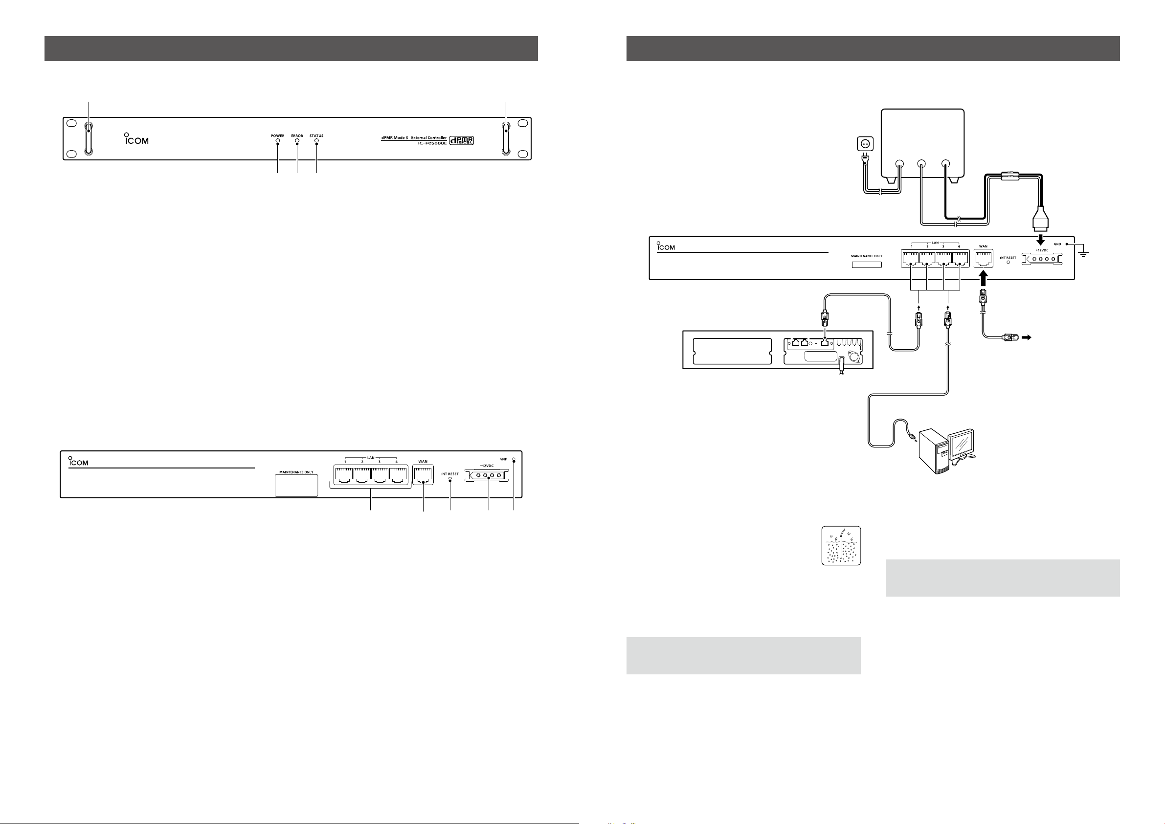
D Rear panel connection
UC-FR5000SE
AC outlet
BUS-1 BUS-2 LAN
DC power supply
(at least 3 A)
AC cable
12 V DC
Red
+
Black
_
DC power cable
To a router
D Rear panel
q LAN CONNECTORS [LAN]
z Connects to the repeaters that the UC-FR5000SE
is installed in.
• Up to 32 units can be connected with an Ethernet
hub.
z Connects to the PC that the CS-FC5000 is
installed in for the remote control operation.
• You can set the network settings with the PC. (p. 4)
w WAN CONNECTOR [WAN]
Connects to the PC that the CS-FC5000SCS is
installed in for the Multi-site trunking operation.
The PC is usually connected via a router.
e INT RESET BUTTON
Hold down for 5 seconds to initialize the settings.
• All set contents of the controller, including the IP
address and password are reset to the factory defaults.
• The Status indicator blinks orange while resetting.
q e trw
r DC POWER CONNECTOR [+12VDC]
Connect a supplied DC power cable from this
connector to an external 12 V DC power supply
(User supplied).
See page 3 for the connection details.
t GROUND TERMINAL [GND]
Connect this terminal to ground to prevent
electrical shocks, interference from other
electronic devices, and other problems.
See page 3 for grounding details.
• Grounding
To prevent electrical shock, television
interference (TVI), broadcast interference
(BCI) and other problems, ground the
controller using the GROUND [GND]
terminal on the rear panel.
For the best results, connect a heavy gauge wire
or strap to a long ground rod. Make the distance
between the [GND] terminal and the ground rod as
short as possible.
R WARNING! NEVER connect the [GND] terminal
to a gas or electric pipe, since the connection could
cause an explosion or electric shock.
to an Ethernet port
PC
• Power supply
Conrm the controller’s power is OFF when
connecting the DC power cable.
CAUTION: Voltages greater than 13.2 V DC will
damage the controller. Check the source voltage
before connecting the power cable.
– 2 – – 3 –
 Loading...