

Page 1
Version 1.0
December 2016
NXDN™
IC-F5400D/IC-F6400D SERIES
PRODUCT GUIDE
PGX-IC-F5400D/F6400D-V1.0
Page 2

NXDN™ IC-F5400D/IC-F6400D SERIES PRODUCT GUIDE
PREFACE
This product guide is made to promote our new products, the IC-F5400D/IC-F6400D transceivers. The new
product's technology components are described in this document, and you will understand the target users,
built-in functions, and sales points of these transceivers. This product guide's target users are dealer sales
staff members who are going to sell these transceivers for the first time.
Icom hopes this product guide will help you to promote sales of the IC-F5400D/IC-F6400D series
transceivers.
Trademarks
Icom, Icom Inc. and the Icom logo are registered trademarks of Icom Incorporated (Japan) in Japan, the
United States, the United Kingdom, Germany, France, Spain, Russia, Australia, New Zealand, and/or other
countries.
COMMANDMIC is a trademark of Icom Incorporated.
NXDN is a trademark of Icom Incorporated and JVC Kenwood Corporation.
The Bluetooth
such marks by Icom Inc. is under license.
LTR is a trademark of the E.F. Johnson Technologies, INC.
3M, Peltor, and WS are trademarks of 3M Company.
All other trademarks are the properties of their respective holders.
© 2016 Icom Inc.
®
word mark and logos are registered trademark owned by Bluetooth SIG, Inc. and any use of
2
Page 3

TABLE OF CONTENTS
NXDN™ IC-F5400D/IC-F6400D SERIES PRODUCT GUIDE
SECTION 1
SECTION 2 PRODUCT RANGE ............................................................................................................. 11
SECTION 3 COMPARISON WITH EXISTING MODELS ....................................................................... 12
SECTION 4 NEW FUNCTION INTRODUCTION .................................................................................... 16
SECTION 5 ACCESSORIES ................................................................................................................... 22
APPENDIX REQUIRED EQUIPMENT FOR SYSTEM CONSTRUCTION ............................................. 25
PRODUCT OUTLINES .......................................................................................................... 4
1-1 ABOUT THE PRODUCT OUTLINES, SALES POINTS, AND TARGET USERS ........ 4
1-2 IC-F5400D/IC-F6400D’S SPECIFICATIONS ............................................................... 9
3-1 FUNCTION COMPARISON BETWEEN THE IC-F5400D/IC-F6400D AND
EXISTING MODELS .................................................................................................. 12
3-2 FUNCTION COMPARISON BETWEEN THE IC-F5400D/IC-F6400D AND
IC-F5060D/IC-F6060D ............................................................................................... 13
3-3 SPECIFICATION COMPARISON BETWEEN IC-F5400D AND IC-F5060D ............. 14
3-4 SPECIFICATION COMPARISON BETWEEN IC-F6400D AND IC-F6060D ............. 15
3
Page 4
NXDN™ IC-F5400D/IC-F6400D SERIES PRODUCT GUIDE
SECTION 1 PRODUCT OUTLINES
1-1 ABOUT THE PRODUCT OUTLINES, SALES POINTS, AND TARGET USERS
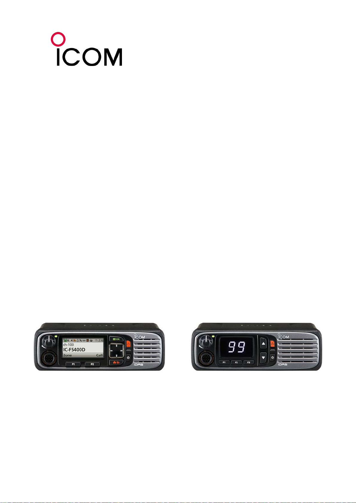
About the IC-F5400D/IC-F6400D series transceivers
The IC-F5400D/IC-F6400D series transceivers have a drastically changed appearance from traditional Icom
land mobile transceivers, and operability that adapts a diversified operating style. In addition, the
transceivers are compatible with NXDN™ Single-site trunking and Multi-site trunking systems by utilizing an
activation license.
Sales point
• Model line-up suitable for various operating purposes.
IC-F5400D/IC-F6400D IC-F5400DS/IC-F6400DS
Equipped with a color LCD Equipped with a 7 segment display
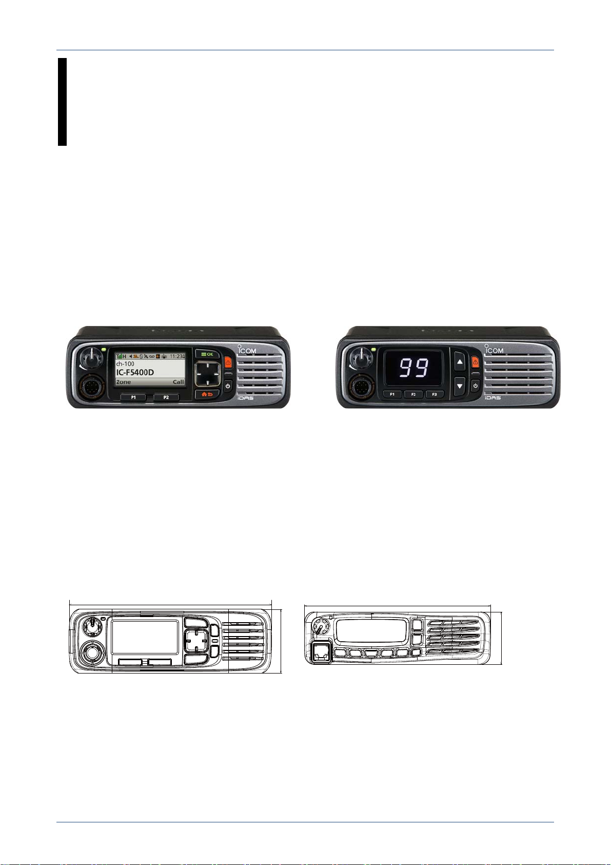
• Equipped with larger-sized keys
Enlarged function keys are built-in to the IC-F5400D/IC-F6400D compared to the IC-F5060D/IC-F6060D
series transceivers. In addition, the built-in [UP]/[DOWN]/[LEFT]/[RIGHT] keys improves operability, and
menu selection.
• Equipped with a color LCD
The IC-F5400D/IC-F6400D series transceivers have a color LCD. The size of the LCD is larger than the
IC-F5060D/IC-F6060D series transceivers, so the visibility is also drastically improved.
Front view and size comparison
174
160
55
45
IC-F5400D/IC-F6400D
IC-F5060D/IC-F6060D
• Improved waterproof/dustproof
The waterproof/dustproof grade is improved from IP54 (controller only) to IP55 (both controller and main
unit), compared to the IC-F5060D/IC-F6060D series transceivers.
4
Page 5
NXDN™ IC-F5400D/IC-F6400D SERIES PRODUCT GUIDE
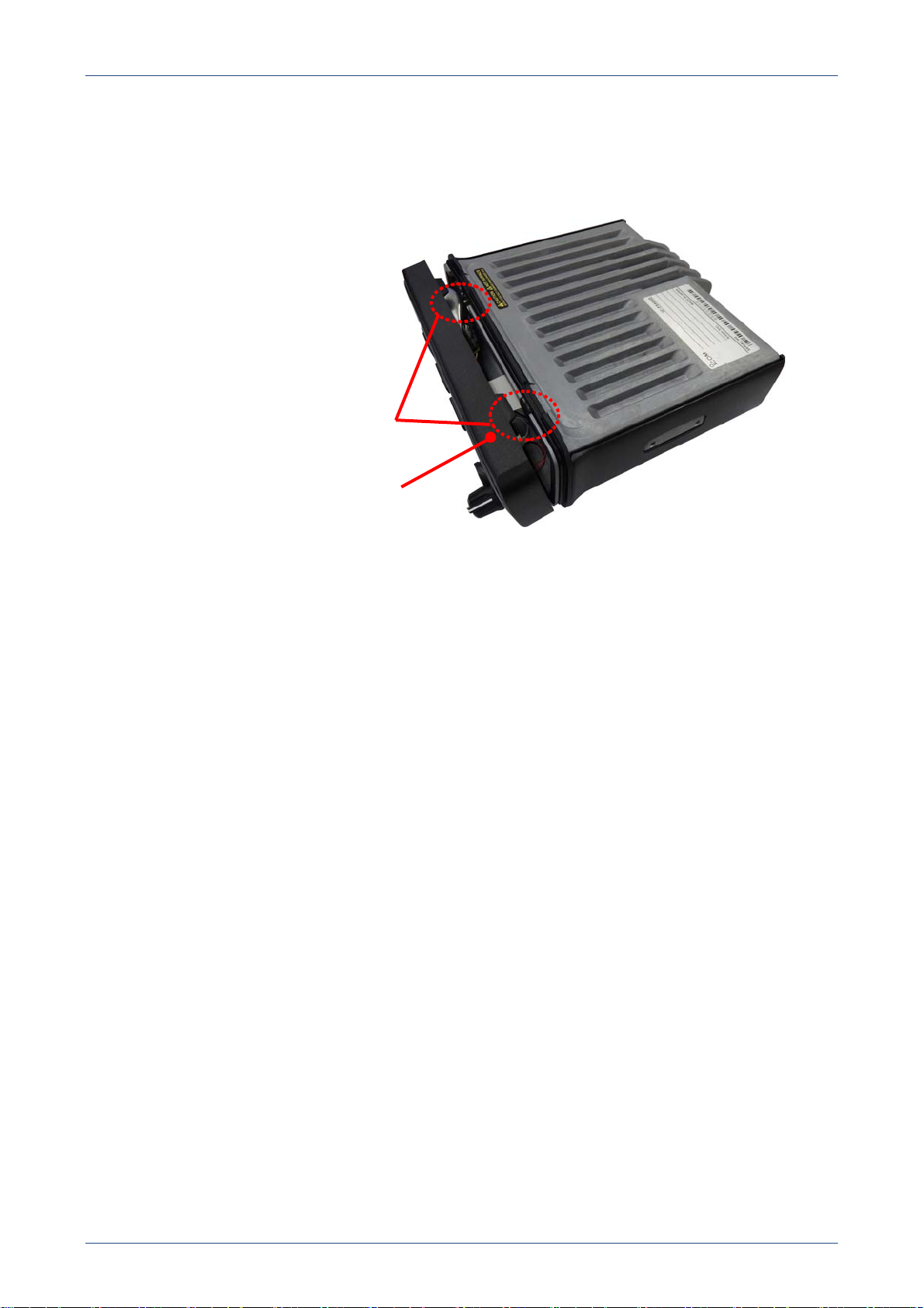
• Improved optional unit attachment
The controller can be detached without using a screw driver. Therefore, the optional unit can easily be
attached.
To detach the controller, pull up on the
latches to unlock the controller.
Controller
Bottom view of the main unit.
5
Page 6
NXDN™ IC-F5400D/IC-F6400D SERIES PRODUCT GUIDE
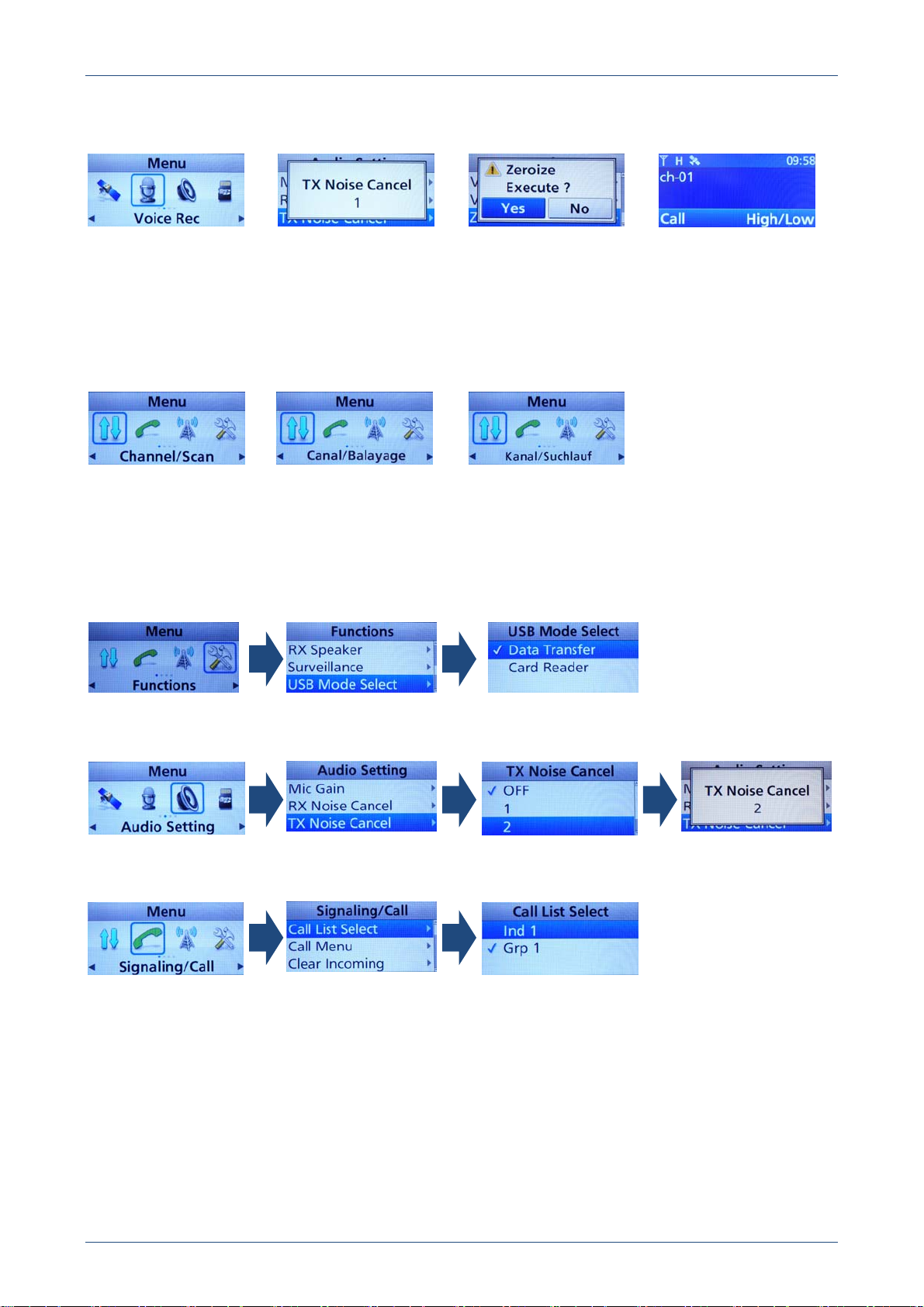
• A 2.37 inch large size color LCD
You can easily see a lot of information on the 320 × 150 dot color LCD display.
You can set the menu items to be visible or invisible in the programming software.
Menu screen
Message screen
Execution confirmation
screen
Night mode screen
• Local language support
Menu item names and messages can be displayed in languages other than English.
NOTE: Names and messages in languages can be preprogrammed using the programming software.
If the main unit firmware revision is 1.6 or later, English, German, French, Spanish, Russian, and Chinese
are supported.
English
French
German
• A user interface improves the operability compared with previous Icom land mobile transceivers.
You can reach desired operations and/or settings by only selecting the icon, or from a list on the menu
screen.
USB mode selecting example
TX noise canceling setting example
Target ID selecting example
6
Page 7
NXDN™ IC-F5400D/IC-F6400D SERIES PRODUCT GUIDE
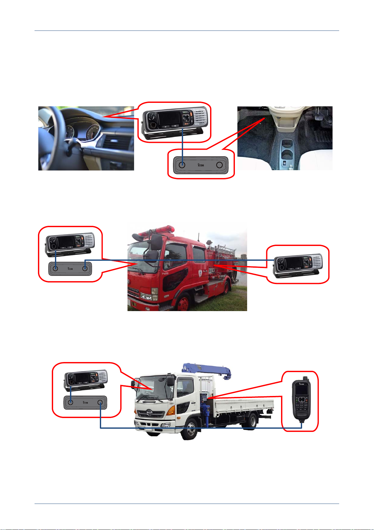
• Various operation styles (Available only for IC-F5400D/IC-F6400D)
IC-F5400D/IC-F6400D transceiver can be operated in the following operation styles. Each operation style
requires main unit firmware revision 1.6 or later.
Detached controller style
You can install the controller close to the operator. Therefore, you can efficiently use the limited space in
a vehicle or the top of a desk.
Dual head controller style
You can attach two controllers, one near the driver seat and one near the operation panel of a fire engine.
Therefore, you can operate the transceiver from either location.
COMMANDMIC™ and detached controller style
You can operate the transceiver from the driver seat in a mobile crane using the controller, or at the crane
controls using the COMMANDMIC™.
7
Page 8

Target users
NXDN™ IC-F5400D/IC-F6400D SERIES PRODUCT GUIDE
B & I markets
(Transport, and so on)
Headquarters of security services
Public works (Electric power
industry, Water services,
and so on)
Construction sites
Public safety
Taxi companies
Transportation businesses
• Users who require the AES/DES encryption function.
• Users who require languages other than English.
8
Page 9

NXDN™ IC-F5400D/IC-F6400D SERIES PRODUCT GUIDE
1-2 IC-F5400D/IC-F6400D’S SPECIFICATIONS
Model name IC-F5400D IC-F6400D
Version
Destination
Frequency coverage
Number of conventional channels
Type of emission
Intermediate frequency
Power supply voltage
High
TX
Current drain
(approximately)
Antenna impedance
Microphone impedance
Audio impedance
Operating temperature range
Dimensions (W H D)
(Projections not included)
Weight (approximately)
Output power (at 13.6 V DC)
Modulation
Maximum frequency deviation
Frequency error
Spurious emissions
Adjacent channel power
Audio harmonic distortion
FSK error
FM hum and noise (without CCITT filter)
Limitation characteristics of the modulator
A: Analog
D: Digital
Low (at 25 W)
Maximum audio
RX
Stand by
TRANSMITTER
USA-01, USA-11
GENERAL
136 ~ 174 MHz
1,024 ch/128 zones [IC-F5400D, IC-F6400D]
4,000 ch/128 zones [The license is activated.]
A: 11K0F3E (15.0 kHz)
D: 4K00F1E, D (6.25 kHz); 8K30F1E, D (12.5 kHz)
9.0 A typical (at 50 W) 8.8 A typical (at 45 W)
900 mA typical
(Internal speaker)
370 mA typical 270 mA typical
90 dB typical 80 dB typical
#01, #11 #01, #11, #21, #31
USA-01, USA-11, USA-21,
USA-31
380 ~ 470 MHz
450 ~ 512 MHz
99 ch [IC-F5400DS/IC-F6400DS]
1st: 49.95 MHz, 2nd: 450 kHz
13.6 V DC nominal Negative ground
5.0 A typical
800 mA typical
(Internal speaker)
50 nominal
600
4
–30 °C ~ +60 °C; –22 °F ~ +140 °F
55 150 mm;
174
6.8 2.2 5.9 inches
1.5 kg; 3.3 lb
50 W 45 W
Frequency modulation, FSK modulation
A: ±2.5 kHz
±1.0 ppm
A: 66 dB typical
D: 66 dB typical (6.25 kHz),
67 dB typical (12.5 kHz)
0.5% typical @ AF 1 kHz 40% deviation
1% typical (D: 6.25 kHz/12.5 kHz)
54 dB typical
70% ~ 100% of max. deviation
9
Page 10

NXDN™ IC-F5400D/IC-F6400D SERIES PRODUCT GUIDE
Model name IC-F5400D IC-F6400D
RECEIVER
• 0.22 V typical
@ 12 dB SINAD
Sensitivity
• 6.0 dBV (EMF) typical
@ 1% BER (D: 6.25 kHz)
• 5.0 dBV (EMF) typical
@ 1% BER (D: 12.5 kHz)
Audio power output
4.0 W typical @ 5% distortion into 4
Adjacent channel selectivity
Spurious response rejection
A: 78 dB typical
Intermodulation
D: 70 dB typical
(6.25 kHz/12.5 kHz)
Hum and noise (without CCITT filter)
Squelch sensitivity (Threshold)
0.22 V typical 0.25 V typical
A: Analog
D: Digital
Specifications: Measurements made in accordance with TIA-603.
• 0.25 V typical
@ 12 dB SINAD
• 6.0 dBV (EMF) typical
@ 1% BER (D: 6.25 kHz)
• 5.0 dBV (EMF) typical
@ 1% BER (D: 12.5 kHz)
A: 72 dB typical
D: 65 dB typical (6.25 kHz),
68 dB typical (12.5 kHz)
85 dB typical
A: 75 dB typical
D: 70 dB typical
(6.25 kHz/12.5 kHz)
48 dB typical
10
Page 11

NXDN™ IC-F5400D/IC-F6400D SERIES PRODUCT GUIDE
SECTION 2 PRODUCT RANGE
The IC-F5400D/IC-F6400D series transceivers are excellent in operability, built-in functions, and scalability.
The transceivers are positioned as high grade land mobile transceivers, as shown in the following positioning
map. You can see that the IC-F5400D/IC-F6400D series transceivers are higher grade than the ICF5060D/IC-F6060D series transceivers on the map.
Product grade
(High)
IC-F5400D series
(2016)
IC-F5060 series
(2006.12-)
IC-F5120D series
(2010.11-)
11
(New)
Released
Page 12
NXDN™ IC-F5400D/IC-F6400D SERIES PRODUCT GUIDE
SECTION 3 COMPARISON WITH EXISTING MODELS
3-1 FUNCTION COMPARISON BETWEEN THE IC-F5400D/IC-F6400D AND
EXISTING MODELS
Models
Functions
IC-F5400D
IC-F6400D
Series
IC-F5060D
IC-F6060D
Series
IC-F5120D
IC-F6120D
Series
YES
NXDN™ Type-D single-site trunking
(Optional
ISL-UGMTR is
YES YES
required.)
YES
NXDN™ Type-D multi-site trunking
(Optional
ISL-UGMTR is
YES None
required.)
PTT ID
Individual ID List
Talkgroup ID List
Log for Individual Call
RX Group
Block Decode
RAN code
Status
Short Data Message (SDM)
Call Alert
Radio Check
Stun/Revive/Kill
Remote Monitor
Digital voice scrambler
Multiple languages
(4 or less keys)
DES
(5 or more keys)
(Optional UT-134 is
YES YES YES
YES
(Max. 1,000
YES
(Max. 1,000
ID)
ID)
YES
(Max. 500 ID)
YES
(Max. 500 ID)
YES
(Max. 500 ID)
YES
(Max. 500 ID)
YES YES YES
YES None None
YES YES YES
YES YES YES
YES YES YES
YES YES YES
YES YES YES
YES YES RX only
YES YES RX only
YES YES RX only
YES YES YES
YES None None
YES None None
YES
None None
required.)
YES
AES
(Optional UT-134
and ISL-AKAES are
None None
required.)
GPS unit
GPS position data TX/RX
Built-in
(Optional UX-241 is
required.)
TX/RX TX/RX TX only
Optional
(User supplied)
Optional
(User supplied)
Emergency function
Emergency key
Lone Worker
YES YES YES
YES YES YES
12
Page 13

NXDN™ IC-F5400D/IC-F6400D SERIES PRODUCT GUIDE
3-2 FUNCTION COMPARISON BETWEEN THE IC-F5400D/IC-F6400D AND
Single-site conventional
Multi-site conventional
Single-site trunking
Multi-site trunking
Analog mode
6.25 kHz Digital mode
12.5 kHz Digital mode
Analog/Digital mix mode
25 kHz bandwidth operation
Voice announcement
Voice Recording/Playback function
Active Noise Cancelling (ANC)
TX Audio Equalizer
RX Audio Equalizer
Lone worker function
Radio Check
Stun/Kill/Revive
Remote Monitor
Call Alert
Emergency
Short Data Message (SDM)
Status Message
Digital voice scrambler
56 bit DES encryption
256 bit AES encryption
Transparent data mode
OAA (Over-the-Air Alias)
OTAP (Over-The-Air Programming)
OTAR (Over-The-Air-Re-keying)
CTCSS
DTCS
2 Tone
5 Tone
DTMF
MDC1200
LTR™ trunking
GPS receiver
Bluetooth®
microSD/SDHC memory card slot
USB connector
Dual head controller
COMMANDMIC™
IC-F5060D/IC-F6060D
FUNCTION
IC-F5400D/IC-F6400D
SERIES
Operation type
YES YES
YES YES
Optional YES
Optional YES
YES YES
YES YES
YES None
YES YES
YES (Optional for [USA]) None
Voice functions
YES None
YES
(A microSD or microSDHC
card is required.)
YES None
YES None
YES None
Digital functions
YES YES
YES YES
YES YES
YES YES
YES YES
YES YES
YES YES
YES YES
YES YES
YES
(4 keys: Default)
(64 keys: Optional)
Optional None
YES None
YES None
Optional None
Optional None
Analog functions
YES YES
YES YES
YES YES
YES YES
YES YES
YES YES
YES YES
Hardwares
YES
(Optional UX-241 is required.)
YES None
YES None
YES None
Optional None
Optional None
IC-F5060D/IC-F6060D
(User supplied.)
SERIES
None
None
None
13
Page 14

NXDN™ IC-F5400D/IC-F6400D SERIES PRODUCT GUIDE
3-3 SPECIFICATION COMPARISON BETWEEN IC-F5400D AND IC-F5060D
SPECIFICATIONS IC-F5400D SERIES IC-F5060D SERIES
GENERAL
Channel capacity
Type of emission
Intermediate frequency
High (50 W)
TX
RX
Low2 (25 W)
Maximum
audio
Stand by
Current drain
(approximately)
Dimensions (W H D)
(Projections not included)
IP rating
Weight (approximately)
FM hum and noise (without CCITT
filter)
Spurious emissions
Adjacent channel power
Audio harmonic distortion
FSK error
Sensitivity
Adjacent channel selectivity
Spurious response rejection
Intermodulation
Hum and noise (without CCITT filter)
Squelch sensitivity (Threshold)
A: Analog
D: Digital
1,024 channels/128 Zones
(Maximum: 4,000 channels)
A: 11K0F3E
D: 4K00F1E, D (6.25 kHz)
8K30F1E, D (12.5 kHz)
1st: 49.95 MHz
2nd: 450 kHz
9.0 A typical 14.0 A
5.0 A typical 7.0 A
900 mA typical
(Internal speaker)
370 mA typical 300 mA
55 150 mm
174
6.8 2.2 5.9 inches
IP55 IP54 (Front panel only)
1.5 kg; 3.3 lb 1.3 kg; 2.9 lb
TRANSMITTER
54 dB typical 40 dB typical
90 dB typical 75 dB typical
A: 66 dB typical
D: 66 dB typical (6.25 kHz)
67 dB typical (12.5 kHz)
0.5% typical 3% typical
1% typical (D) 5% maximum (D)
RECEIVER
A: 0.22 V typical
@ 12 dB SINAD
D: 6.0 dBV (EMF) typical
@ 1% BER (6.25 kHz)
5.0 dBV (EMF) typical
@ 1% BER (12.5 kHz)
A: 72 dB typical
D: 65 dB typical (6.25 kHz)
68 dB typical (12.5 kHz)
85 dB typical 90 dB typical
A: 78 dB typical
D: 70 dBV (EMF) typical
(6.25 kHz/12.5 kHz)
48 dB typical 45 dB typical
0.22 V typical 0.25 V typical
512 channels/128 Zones
A: 11K0F3E
D: 4K00F1E, D (6.25 kHz)
1st: 46.35 MHz
2nd: 450 kHz
1200 mA
(Internal speaker)
160 45 150 mm
6.3 1.8 5.9 inches
A: 60 dB minimum (6.25 kHz)
A: 0.25 V typical
@ 12 dB SINAD
A: 75 dB typical (6.25 kHz)
A: 77 dB typical (6.25 kHz)
14
Page 15

NXDN™ IC-F5400D/IC-F6400D SERIES PRODUCT GUIDE
3-4 SPECIFICATION COMPARISON BETWEEN IC-F6400D AND IC-F6060D
SPECIFICATIONS IC-F6400D SERIES IC-F6060D SERIES
GENERAL
Channel capacity
Type of emission
Intermediate frequency
High (50 W)
TX
RX
Low2 (25 W)
Maximum
audio
Stand by
Current drain
(approximately)
Dimensions (W H D)
(Projections not included)
IP rating
Weight (approximately)
FM hum and noise (without CCITT
filter)
Spurious emissions
Adjacent channel power
Audio harmonic distortion
FSK error
Sensitivity
Adjacent channel selectivity
Spurious response rejection
Intermodulation
Hum and noise (without CCITT filter)
A: Analog
D: Digital
1,024 channels/128 Zones
(Maximum: 4,000 channels)
A: 11K0F3E
D: 4K00F1E, D (6.25 kHz)
8K30F1E, D (12.5 kHz)
1st: 49.95 MHz
2nd: 450 kHz
8.8 A typical 14.0 A
5.0 A typical 7.0 A
800 mA typical
(Internal speaker)
270 mA typical 300 mA
55 150 mm
174
6.8 2.2 5.9 inches
IP55 IP54 (Front panel only)
1.5 kg; 3.3 lb 1.3 kg; 2.9 lb
TRANSMITTER
54 dB typical 40 dB typical
80 dB typical 75 dB typical
A: 66 dB typical
D: 66 dB typical (6.25 kHz)
67 dB typical (12.5 kHz)
0.5% typical 3% typical
1% typical (D) 5% maximum (D)
RECEIVER
A: 0.25 V typical
@ 12 dB SINAD
D: 6.0 dBV (EMF) typical
@ 1% BER (6.25 kHz)
5.0 dBV (EMF) typical
@ 1% BER (12.5 kHz)
A: 72 dB typical
D: 65 dB typical (6.25 kHz)
68 dB typical (12.5 kHz)
85 dB typical 90 dB typical
A: 75 dB typical
D: 70 dBV (EMF) typical
(6.25 kHz/12.5 kHz)
48 dB typical 45 dB typical
512 channels/128 Zones
A: 11K0F3E
D: 4K00F1E, D (6.25 kHz)
1st: 46.35 MHz
2nd: 450 kHz
1200 mA
(Internal speaker)
160 45 150 mm
6.3 1.8 5.9 inches
A: 60 dB minimum (6.25 kHz)
A: 0.25 V typical
@ 12 dB SINAD
A: 75 dB typical (6.25 kHz)
A: 77 dB typical (6.25 kHz)
15
Page 16

NXDN™ IC-F5400D/IC-F6400D SERIES PRODUCT GUIDE
SECTION 4 NEW FUNCTION INTRODUCTION
The new functions are included in the main firmware revision 1.6 or later.
• Bluetooth
A third party Bluetooth
®
function
®
headset (3M™ PELTOR™ WS™ Headset XP, 3M™ PELTOR™ WS™ ProTac XP,
or 3M™ PELTOR™ WS™ Alert XP)* can be used for wireless headset operation. This allows you a flexible
installation style, and will not restrict operator’s activity caused by the connection cable and its length.
The adopted Bluetooth
®
is compatible with Class 1 and Bluetooth
®
version 2.1+EDR, and the details of the
compatible profile are as shown in the table below.
*Only PTT switch action is checked. Icom does not guarantee all functions and performance of the
Bluetooth
®
headset.
Table 4-1. Compatible profile
Profile Application
HFP (Hands-Free Profile)
Used when transmitting/receiving a signal, hands
free.
HSP (Headset Profile) Used with a connected headset.
Used when connecting two devices using a virtual
SPP (Serial Port Profile)
serial port. (Used for programming the transceiver
without a programming cable.)
• Active Noise Cancelling function
The Active Noise Cancelling function, which is already used in Icom marine transceivers, can suppress
background noise. By using this function, you can transmit clear voice even in a noisy environment, such as
in a downtown area, or near a high traffic main road. The function can also be activated while receiving a call.
The suppression level of the Active Noise Cancelling function can be set to one of three levels. Up to 30%*
of noise for transmit audio, and up to 90%* of noise for receive audio will be suppressed.
*Theoretical value.
Background noise
Voice Background noise is suppressed. Voice
Active Noise Cancelling
Figure 4-1. Active Noise Cancelling function’s image
16
Page 17

NXDN™ IC-F5400D/IC-F6400D SERIES PRODUCT GUIDE
• Voice recorder function
The voice recorder function can record both transmitting and receiving voice audio onto a microSD* or
microSDHC* card (hereinafter called microSD* card). The recorded voice audio can be played back on the
transceiver or a PC.
*User supplied.
The voice recorder function specifications are as follows.
Digitization method: PCM
Sampling frequency: 8 kHz
Bit rate: 16 bit
File format: WAVE format
The recordable time for each microSD card’s capacity is shown in the following table.
Table 4-2. The recordable time (theoretical value)
Card type Card capacity Recordable time
512 MB 8 hours
microSD
1 GB 15.6 hours
2 GB 31.3 hours
4 GB 62.5 hours
microSDHC
8 GB 125 hours
16 GB 250 hours
32 GB 500 hours
• The DES/AES encryption function
A 56 bit DES encryption function can be used. (The IC-F5400D/IC-F6400D series transceiver has 4 DES
keys by default.)
When the optional UT-134 is installed in the transceiver, the function will be upgraded as follows.
If you want to use the UT-134, update the main unit firmware to revision 1.6 or later, and program the DES
key with the optional CS-KLD2.
The number of DES encryption keys has been increased from 4 to 64.
When the optional UT-134 is installed, the originally used 4 DES keys must be reentered.
If you purchase the Activation key, 256 bit AES encryption can also be used. In this case, a total of 64
encryption keys that include both AES and DES can be used.
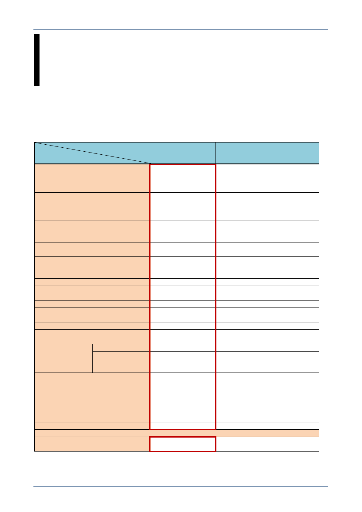
The required items to use the DES/AES encryption function are described in Table 4-3.
Table 4-3. The required items to use the DES/AES encryption function
Transceiver’s default
function.
To use 4 or less DES
encryption keys.
YES NO NO
Activation key is required. NO NO
The optional UT-134 is
required.
Required software to enter
the key.
NO YES YES
CS-F3400D CS-KLD2 CS-KLD2
To use 5 or more DES
encryption keys.
To use AES
encryption keys
YES
(ISL-AKAES)
17
Page 18

NXDN™ IC-F5400D/IC-F6400D SERIES PRODUCT GUIDE
• Transparent data mode
The IC-F5400D/IC-F6400D series transceivers have the Transparent data mode. The Transparent data
mode enables data transmission at 3600 bps. This function enables you to transmit simple measuring data,
such as air temperature, or still images for remote monitoring.
Office PC
(Viewing the received picture)
Sending a picture
Figure 4-2. Transparent data mode application example
• OAA (Over-the Air Alias) function
Even if the IC-F5400D/IC-F6400D series transceivers receive a signal that is not programmed into the Call
List, this function can automatically display and program the caller’s name with an ID. When you add new
transceivers in your system, the transceiver can display the name corresponding to an Individual
ID/Talkgroup ID on the display without reentering, by using this function. If the caller’s name set in the
transceiver is changed, the receiving transceiver automatically changes the ID name.
OAA
Conv ID: 3
Name: TR3
Conv ID: 4
Name: TR4
The ID name “TR3” is automatically programmed as ID 3’s name.
Figure 4-3. OAA example
• 12.5 kHz Digital mode operation
You can select the channel spacing between 6.25 kHz and 12.5 kHz in the digital mode using the
programming software.
• Field programming by Over-The-Air programming (OTAP) can be done (a license is required.)
Even if you have to change the transceiver settings, you can remotely do it without taking it to your dealer, by
using the OTAP function. Installing the software* for the OTAP function onto the PC is required.
*Available in the near future.
18
Page 19

NXDN™ IC-F5400D/IC-F6400D SERIES PRODUCT GUIDE
• Expanding functions by activation licenses
The IC-F5400D/IC-F6400D series transceivers can expand their functions using an activation license. You
can upgrade the transceiver using the programming software. The license is linked to the transceiver's serial
number. Therefore, a unique license is required for each transceiver. The following licenses are sold, or will
be sold in the near future.
Table 4-4. License list
License name Expanding function
ISL-UGMTR For NXDN™ Type-D trunking operation.
ISL-CHEX To increase channel number from 1,024 to 4,000.
ISL-AK25K For 25 kHz (Wide) operation (only [USA]).
ISL-AKAES For AES encryption operation.
ISL-AKSTM For access to the dealer set mode.
• Programming using a microSD card
You can save the transceiver’s setting on a microSD card, or load the saved setting to the transceiver.
Therefore, you can save or change the setting in the field without using the programming software. So, when
multiple operators share one transceiver, you can easily change the transceiver’s setting for each operator
with this function. A microSD card is required.
• GPS position indication
The IC-F5400D/IC-F6400D series transceivers have a built-in GPS receiver, and current position information
can be displayed on the transceiver’s LCD display. You can know your own position by displaying the
information. You can transmit your position information. The transmitted position is used to display the
transceiver’s position on a map by using a third party AVL system.
In addition, other transceiver’s relative position can be displayed on the display. For example, your
transceiver receives position information from the transceiver whose Individual ID name is ID 2, information
is displayed as shown in figure 4-6.
Latitude
Longitude
Altitude
Figure 4-4. Position information display example
ID 2’s latitude
ID 2’s longitude
Direction from own
station to ID 2.
The distance from your
own station to ID 2.
Figure 4-5. ID 2’s position information display example
19
Page 20

NXDN™ IC-F5400D/IC-F6400D SERIES PRODUCT GUIDE
• TX/RX audio equalizer function
This function can improve or correct the TX/RX audio readability by increasing or decreasing particular audio
frequency components. This function requires main unit firmware revision 1.6 or later.
• Hot DTMF function
The IC-F5400D/IC-F6400D series transceiver has the Hot DTMF function that can transmit DTMF signals
without holding down [PTT] when you use a DTMF microphone. This function requires main unit firmware
revision 1.6 or later.
• Dealer set mode function
The dealer set mode can change the frequency without the programming software. If you want to use the
dealer set mode, an optional license (ISL-AKSTM) is required. The following operation is required to enter
the dealer set mode.
Turn OFF the transceiver’s power.
While holding down [P1] and [UP], turn ON the power.
This function requires main unit firmware revision 1.6 or later.
• The controller and main unit can be separated (Only IC-F5400D/IC-F6400D)
If the main unit firmware revision is 1.6 or later, 3 styles of controller separate operation can be used. The
required equipment for each style is listed in Tables 4-5, 4-6, and 4-7.
Detached controller style
SEPARATION CABLE
for RMK-5 or RMK-7
SEPARATION KIT
MICROPHONE
Table 4-5. Required equipment for the detached controller style
Category Product name Quantity
SEPARATION KIT RMK-5 One
OPC-2364 (1.9 m/ 6.2 ft)
SEPARATION CABLE
for RMK-5 or RMK-7
OPC-2365 (3 m/ 9.8 ft)
OPC-2366 (5 m/ 16.4 ft)
Either one
OPC-2367 (8 m/ 26.2 ft)
HM-220 (HEAVY-DUTY MICROPHONE; IP54)
HM-220T (HEAVY-DUTY MICROPHONE WITH DTMF
MICROPHONE
KEYPAD; IP54)
Either one
HM-221 (MICROPHONE; IP55)
HM-221T (DTMF MICROPHONE; IP55)
20
Page 21

NXDN™ IC-F5400D/IC-F6400D SERIES PRODUCT GUIDE
Dual head controller style
SEPARATION CABLE
for RMK-5 or RMK-7
DUAL-HEAD
SEPARATION KIT
MICROPHONE
Table 4-6. Required equipment for the dual head controller style
Category Product name Quantity
DUAL-HEAD
SEPARATION KIT
RMK-7 One
OPC-2364 (1.9 m/ 6.2 ft)
SEPARATION CABLE
for RMK-5 or RMK-7
OPC-2365 (3 m/ 9.8 ft)
OPC-2366 (5 m/ 16.4 ft)
Either two
OPC-2367 (8 m/ 26.2 ft)
HM-220 (HEAVY-DUTY MICROPHONE; IP54)
HM-220T (HEAVY-DUTY MICROPHONE WITH DTMF
MICROPHONE
KEYPAD; IP54)
Either two
HM-221 (MICROPHONE; IP55)
HM-221T (DTMF MICROPHONE; IP55)
COMMANDMIC™ and detached controller style
SEPARATION CABLE
for RMK-5 or RMK-7
MICROPHONE
SEPARATION KIT
COMMANDMIC™
CONNECTION CABLE
for HM-218
Table 4-7. Required equipment for the COMMANDMIC™ and detached controller style
Category Product name Quantity
SEPARATION KIT RMK-5 One
OPC-2364 (1.9 m/ 6.2 ft)
SEPARATION CABLE
for RMK-5 or RMK-7
OPC-2365 (3 m/ 9.8 ft)
OPC-2366 (5 m/ 16.4 ft)
Either one
OPC-2367 (8 m/ 26.2 ft)
COMMANDMIC™ HM-218 (IP55) One
CONNECTION CABLE
for HM-218
OPC-2373 (1.9 m/ 6.2 ft)
OPC-2374 (8 m/ 26.2 ft)
Either one
HM-220 (HEAVY-DUTY MICROPHONE; IP54)
HM-220T (HEAVY-DUTY MICROPHONE WITH DTMF
MICROPHONE
KEYPAD; IP54)
Either one
HM-221 (MICROPHONE; IP55)
HM-221T (DTMF MICROPHONE; IP55)
21
Page 22

NXDN™ IC-F5400D/IC-F6400D SERIES PRODUCT GUIDE
SECTION 5 ACCESSORIES
Current optional accessories available for the IC-F5400D/IC-F6400D series transceivers are shown below.
(Some accessories may not be available in some countries.)
MICROPHONES
HM-221 MICROPHONE
Meets IP55 waterproof/dustproof
HM-220 HEAVY-DUTY MICROPHONE
Meets IP54 waterproof/dustproof
HM-218 COMMANDMIC™
Meets IP55 waterproof/dustproof
(Optional RMK-5 is required.)
HM-221T DTMF MICROPHONE
Meets IP55 waterproof/dustproof
HM-220T HEAVY-DUTY MICROPHONE WITH
DTMF KEYPAD
Meets IP54 waterproof/dustproof
SM-29 DESKTOP MICROPHONE
22
Page 23

EXTERNAL SPEAKERS
SP-30 (Cable length: 2.6 m/ 8.5 ft)
SEPARATION KITS AND CABLES
RMK-5 SEPARATION KIT
(firmware revision 1.6 or later required.)
Connection example
SEPARATION CABLES for RMK-5 or RMK-7
OPC-2364 (Cable length: 1.9 m/ 6.2 ft)
OPC-2365 (Cable length: 3 m/ 9.8 ft)
OPC-2366 (Cable length: 5 m/ 16.4 ft)
OPC-2367 (Cable length: 8 m/ 26.2 ft)
OPC-2364
NXDN™ IC-F5400D/IC-F6400D SERIES PRODUCT GUIDE
SP-35 (Cable length: 2 m/ 6.6 ft)
SP-35L (Cable length: 6 m/ 19.7 ft)
RMK-7 DUAL-HEAD SEPARATION KIT
(firmware revision 1.6 or later required.)
Connection example
CONNECTION CABLES for HM-218
OPC-2373 (Cable length: 1.9 m/ 6.2 ft)
OPC-2374 (Cable length: 8 m/ 26.2 ft)
OPC-2373
23
Page 24

OTHERS
DC POWER CABLES
OPC-1132 (Cable length: 3 m/ 9.8 ft)
OPC-347 (Cable length: 7 m/ 23 ft)
OPC-1132
UT-134 AES/DES ENCRYPTION UNIT
CS-F3400D Programming software
OPC-2363 Programming cable
OPC-2357 Connection cable for OTAR with
DB25 connector
NXDN™ IC-F5400D/IC-F6400D SERIES PRODUCT GUIDE
OPC-2362 ZONE COPY CABLE
(to connect with the IC-F3400D/IC-F4400D series
transceiver)
(Cable length: 80 cm/ 2.6 ft)
UX-241 GPS ANTENNA
(Cable length: 5 m/ 16.4 ft)
CS-KLD2 Key-loader (PC software)
CS-OTPM1 OTAP manager software
ISL-AKAES AES activation key
ISL-UGMTR NXDN™ trunking upgrade key
ISL-AK25K 25 kHz (Wide) activation key
([USA] only)
ISL-CHEX Channel expansion key
ISL-AKSTM Dealer set mode activation key
24
Page 25

NXDN™ IC-F5400D/IC-F6400D SERIES PRODUCT GUIDE
APPENDIX REQUIRED EQUIPMENT FOR SYSTEM
Required equipment to construct a Single-site co nventional system
Items Product name
Repeater IC-FR5000/IC-FR6000
Required equipment to construct a Multi-site conventional system
Items Product name
Repeater IC-FR5000/IC-FR6000
Trunking/Network controller UC-FR5000(#02)
Required equipment to construct a Single-site tru nking system
Items Product name
Repeater
Trunking/Network controller UC-FR5000(#01)
NXDN™ Trunking Upgrade Key ISL-UGMTR
Required equipment to construct a Multi-site trunking system
Items Product name
Repeater
Trunking/Network controller UC-FR5000(#03)
NXDN™ Trunking Upgrade Key ISL-UGMTR
CONSTRUCTION
(The CF-FR5000MC is installed.)
IC-FR5000/IC-FR6000
(UR-FR5000/UR-FR6000)
(The same numbers of keys are required as the number of
transceivers.)
IC-FR5000/IC-FR6000
(UR-FR5000/UR-FR6000)
(The CF-FR5000MT is installed.)
(The same number of keys as the number of transceivers is
required)
25
Page 26

 Loading...