

Icom IC-F5360D, IC-F6360D Instructions Manual
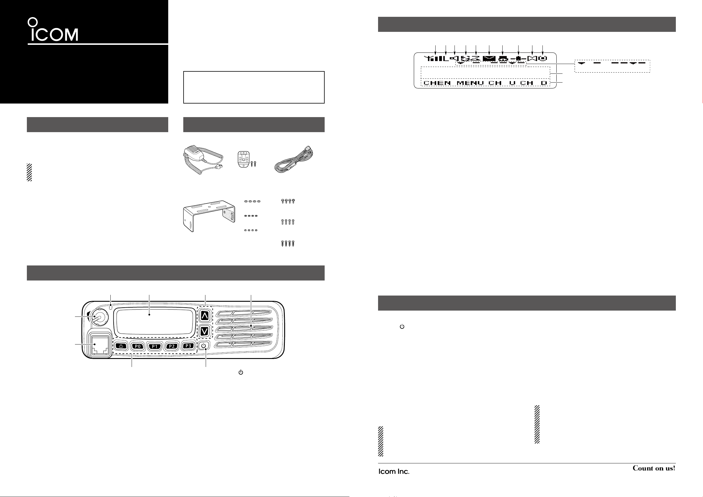
FUNCTION DISPLAY
Microphone
Microphone hanger
and screw set
DC power cable
Mounting bracket
Flat washers
Spring washers
Bracket bolts
Mounting screws
(M5×12)
Self-tapping screws
(M5×16)
Nuts
IC-F5360D
INSTRUCTIONS
VHF DIGITAL TRANSCEIVER
Iç-F5360D
UHF DIGITAL TRANSCEIVER
Iç-F6360D
FOREWORD
This instruction sheet includes some functions which are
usable only when they are preset by your dealer. Ask your
dealer for details.
See the operating instructions for details of other functions, and IDAS™ NXDN™ system operations. Ask your
dealer for details.
Icom, Icom Inc. and the Icom logo are registered trademarks of Icom Incorporated (Japan) in Japan, the United States, the United Kingdom, Germany,
France, Spain, Russia and/or other countries.
IDAS and the IDAS logo are trademarks of Icom Incorporated.
NXDN is a trademark of Icom Incorporated and JVC Kenwood Corporation.
All other products or brands are registered trademarks or trademarks of their
respective holders.
PANEL DESCRIPTION
LED indicator Up/Down keys
Function display
Thank you for choosing the IC-F5360D v h f d ig ita l
t r a n s c e i v e r or IC-F6360D u h f di git al t r a n s c e i v e r .
READ ALL INSTRUCTIONS carefully and completely before using your transceiver.
SUPPLIED ACCESSORIES
Speaker
w e r t y u i o !0
q
q SIGNAL STRENGTH INDICATOR
Displays the relative receive signal strength.
w LOW POWER ICON
Appears when low output power is selected.
• When the battery charge decreases to a specied level, low
power is automatically selected.
e AUDIBLE ICON
Appears when the channel is in the ‘audible’ (unmute) ➥
mode.
Appears when a matched signal is received. ➥
r SCRAMBLER ICON
Appears when the Voice Scrambler function is ON.
t SCAN ICON
Appears while scanning.
y MESSAGE ICON
Appears when a received message (Short Data Mes- ➥
sage or Status Message) is stored in the stack memory.
Blinks when an unread message is in the stack mem- ➥
ory.
u BELL ICON
Appears when a matched signal is received, depending
on the presetting.
i GPS ICON
Appears when position data is received.
!4 !5 !6 !7 !8
!3
!1
!2
o HORN ALERT ICON
Appears when the Horn Alert function is ON.
!0 PUBLIC ADDRESS ICON
Appears when the Public Address function is ON.
!1 ALPHANUMERIC READOUT
Displays the operating channel number, channel name,
Menu contents, DTMF code, and so on.
• The display mode automatically switches between one line and
two lines.
!2 KEY ICONS
Displays the assigned function of the [P0], [P1], [P2] and
[P3] front panel keys.
!3 SCAN TARGET ZONE ICON
Appears when the scan target zone is selected.
!4 EXTERNAL SPEAKER ICON
Appears when the external speaker is connected.
!5 AUX A ICON
Appears when the AUX A function is ON.
!6 AUX B ICON
Appears when the AUX B function is ON.
!7 SCAN TARGET CHANNEL ICON
Appears when the scan target channel is selected.
!8 OPERATOR SELECTABLE TONE ICON
Appears when the Operator Selectable Tone function is
ON.
[VOL]
Microphone
connector
Dealer-assignable keys*
([R], [P0], [P1], [P2], [P3])
*Ask your dealer for details.
Power switch [ ]
About the LED indicator D
• Lights red while transmitting.
• Lights green while receiving a signal, or when the squelch
is open.
BASIC OPERATION
Turning power ON D
Push [ ➥ ] to turn ON the power.
Receiving and Transmitting D
Receiving:
Select a channel. q
Push [CH U] or [CH D]. ➥
Push one of the direct channel select keys, [DR 1] to ➥
[DR 5].
Push the ([1] to [9] or [0]) digit keys of the optional ➥
DTMF microphone to enter the channel number when
the Channel Entry function is assigned to the keypad,
or after pushing [CHEN].
When receiving a call, rotate [VOL] to adjust the audio w
output level to a comfortable listening level.
For your reference:
[CHEN]: Channel Entry
[CH U]: CH/GID Up [CH D]: CH/GID Down
[DR 1]: Direct CH/GID 1 [DR 5]: Direct CH/GID 5
See the operating instructions for details.
1-1-32 Kamiminami, Hirano-ku, Osaka 547-0003, Japan
Transmitting:
Wait until the channel is clear to avoid interference.
Take the microphone off hook. q
• While scanning, the scan stops.
Wait for the channel to become clear. w
• The channel is busy when the LED indicator lights green.
While holding down [PTT], speak at a normal voice level. e
Release [PTT] to receive. r
IMPORTANT:
To maximize the readability of your signal:
1. After pushing [PTT], pause briey before you start
speaking.
2. Hold the microphone 5 to 10 cm (2 to 4 inches) from
your mouth, then speak at a normal voice level.
A-7148H-2EX Printed in Japan
© 2014 Icom Inc.
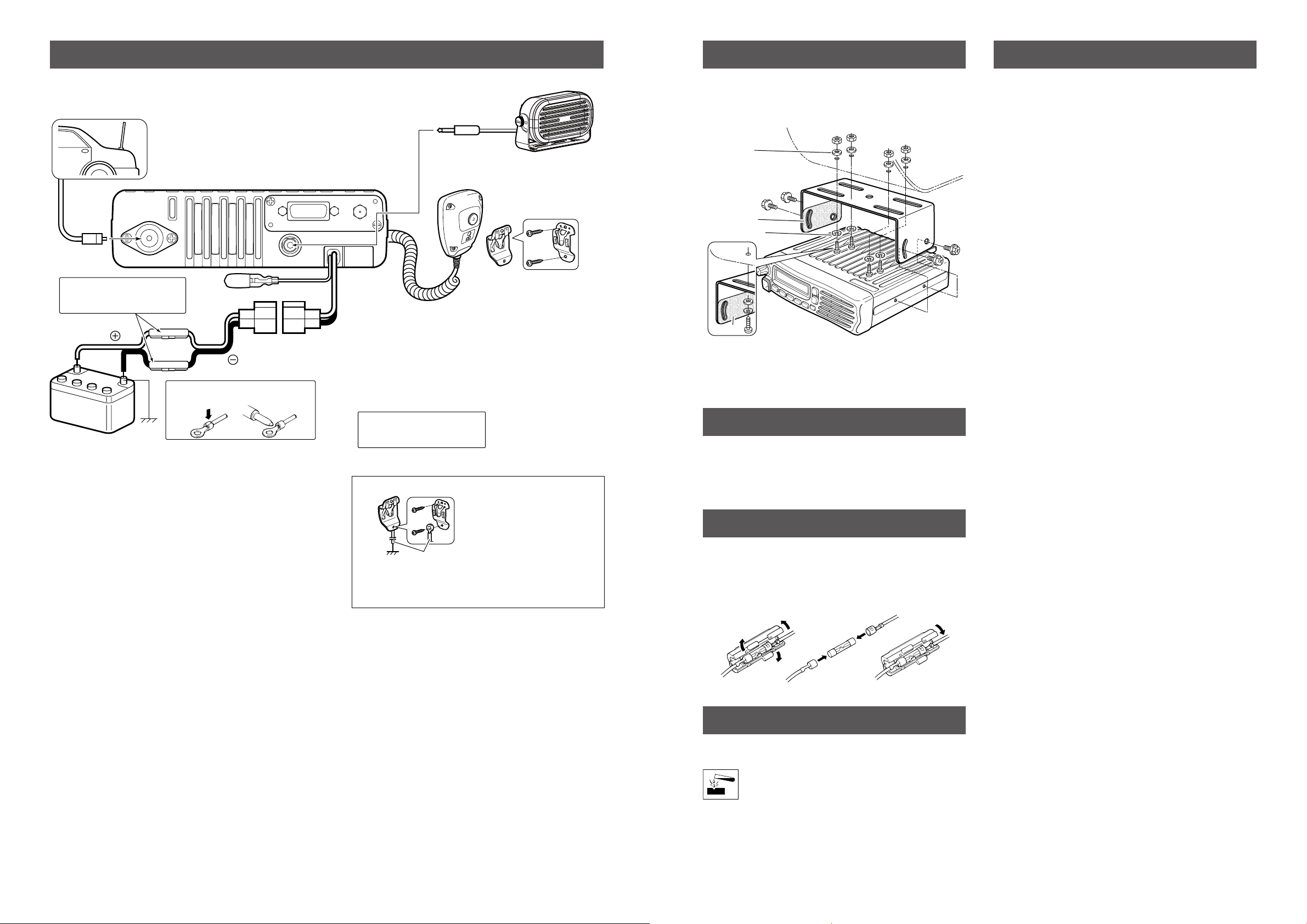
REAR PANEL CONNECTION
Antenna
q ANTENNA CONNECTOR
Connects to an antenna.
Contact your dealer about
antenna selection and
placement.
q
Connects to a GPS antenna.
3.3 V DC output.
R
w EXTERNAL SPEAKER
JACK
Connect a 4–8 ˘
external speaker.
e D-Sub 15-pin
Connect an external unit.
r MICROPHONE HANGER
The microphone on/off hook
functions can be used without
the vehicle’s ground.
t
r
y
Optional speaker
e
w
t IGNITION LEAD
Connects to a ignition line.
R
Do not put a pressure to
this lead.
Binding to the DC power
cable is recommended.
Microphone
y DC POWER RECEPTACLE
Connects to a 12 V DC battery.
Pay attention to polarities.
R WARNING! NEVER connect
to a 24 V battery. This could
damage the transceiver.
Solder
NOTE: Use the terminals as shown
below for the cable connections.
Crimp
Black
Red
12V
Battery
R WARNING! NEVER remove
the fuse-holder from the DC
power cable.
Purchase separately
Connect the microphone hanger to the vehicle’s ground
for microphone on/off hook functions when the optional
microphone (HM-152/T) is used.
When the optional microphone (HM-152/T) is used:
r
r GPS ANTENNA CONNECTOR
CAUTION: When no antenna
is connected, attach the cap
to the connector. Otherwise,
an electrical shock or burn
may occur.
Flat washer
Felt*
Spring washer
When using
self-tapping screws
Felt*
*Felts reduce the vibration effects.
MOUNTING THE TRANSCEIVER
OPTIONS
The universal mounting bracket supplied with your transceiver allows overhead mounting.
• Mount the transceiver securely with the 4 supplied screws
to a thick surface which can support more than 1.5 kg.
ANTENNA
A key element in the performance of any communication
systems is an antenna. Contact your dealer for more information regarding antennas and how to install them.
• OPC-1132/OPC-347 d c p o w e r c a b l e
OPC-1132: 3 m (9.8 ft)
OPC-347: 7 m (23 ft)
• HM-152/HM-152T/HM-148G/HM-148T
h a n d m i c r o p h o n e s
HM-152: Hand microphone
HM-152T: DTMF microphone
HM-148G: Self ground heavy duty microphone
HM-148T: Self ground heavy duty DTMF microphone
The 10-keypad of this microphone can be used
for the DTMF code transmission only.
• SM-26
d e s k t o p m i c r o p h o n e
• SP-30/SP35/SP-35L e x t e r n a l s p e a k e r s
Input impedance: 4 ø
SP-30: Rated input; 20 W, Max. input; 30 W
SP-35/SP35L: Rated input; 5 W, Max. input; 7 W
Approved Icom optional equipment is designed for optimal performance when used with an Icom transceiver.
Icom is not responsible for the destruction or damage to an Icom
transceiver in the event the Icom transceiver is used with equipment
that is not manufactured or approved by Icom.
Some options may not be available in some countries. Please ask
your dealer for details.
FUSE REPLACEMENT
A fuse is installed in the supplied DC power cable. If a fuse
blows or the transceiver stops functioning, track down the
source of the problem if possible, and then replace the damaged fuse with a new rated one.
❑ Fuse rating: 20 A
USE the 20 A fuse only.
CLEANING
If the transceiver becomes dusty or dirty, wipe it clean with a
soft, dry cloth.
DO NOT use harsh solvents such as benzene or
alcohol, as they may damage the transceiver surfaces.
 Loading...