

Page 1
INSTRUCTION MANUAL
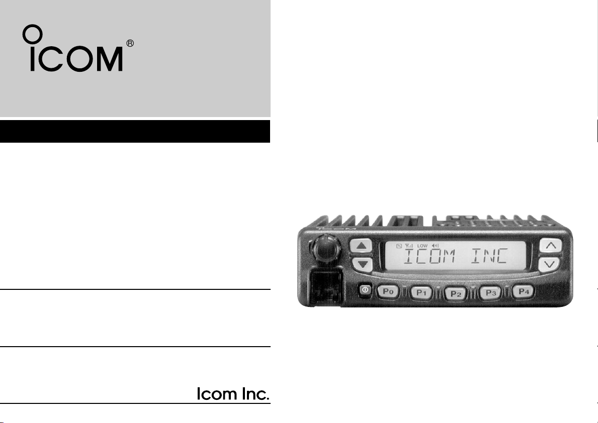
UHF TRANSCEIVER
iF610
iF620
iF621
(For the LTR®/PassPort version)
Page 2
IMPORTANT
PRECAUTION
READ ALL INSTRUCTIONS carefully and complete-
ly before using the transceiver.
SAVE THIS INSTRUCTION MANUAL — This
instruction manual contains important operating instructions for
the IC-F610/IC-F620/IC-F621 UHF TRANSCEIVER.
EXPLICIT DEFINITIONS
WORD DEFINITION
RWARNING
CAUTION
NOTE
Icom, Icom Inc. and the logo are registered trademarks of
Icom Incorporated (Japan) in the United states, the United
Kingdom, Germany, France, Spain, Russia and/or other countries.
®
is a registered trademark of the E.F.Johnson Company.
LTR
All other products or brands are registered trademarks or trademarks of their respective holders.
i
Personal injury, fire hazard or electric shock
may occur.
Equipment damage may occur.
If disregarded, inconvenience only. No risk
of personal injury, fire or electric shock.
RWARNING! NEVER connect the transceiver to an
AC outlet. This may pose a fire hazard or result in an electric
shock.
NEVER connect the transceiver to a power source of more
than 16 V DC such as a 24 V battery. This connection will ruin
the transceiver.
NEVER cut the DC power cable between the DC plug and
fuse holder. If an incorrect connection is made after cutting,
the transceiver might be damaged.
NEVER place the transceiver where normal operation of
the vehicle may be hindered or where it could cause bodily
injury.
NEVER allow children to touch the transceiver.
NEVER expose the transceiver to rain, snow or any liquids.
USE supplied microphone only. Other microphones have
different pin assignments and may damage the transceiver.
Page 3

TABLE OF CONTENTS
DO NOT use or place the transceiver in areas with tem-
peratures below –22°F (–30°C) or above +140°F (+60°C) or,
in areas subject to direct sunlight, such as the dashboard.
AVOID operating the transceiver without running the vehi-
cle’s engine. The vehicle’s battery will quickly run out if the
transceiver transmits while the vehicle’s engine OFF.
AVOID placing the transceiver in excessively dusty envi-
ronments.
AVOID placing the transceiver against walls. This will
obstruct heat dissipation.
AVOID the use of chemical agents such as benzine or
alcohol when cleaning, as they damage the transceiver surfaces.
BE CAREFUL! The transceiver will become hot when
operating continuously for long periods.
For U.S.A. only
CAUTION: Changes or modifications to this transceiver, not
expressly approved by Icom Inc., could void your authority to
operate this transceiver under FCC regulations.
IMPORTANT ........................................................................ i
EXPLICIT DEFINITIONS ..................................................... i
PRECAUTION ..................................................................... i
TABLE OF CONTENTS ...................................................... ii
1 PANEL DESCRIPTION ............................................... 1–2
■ Front panel ................................................................... 1
■ Function display ........................................................... 2
2 CONNECTION AND MAINTENANCE ........................ 3–7
■ Rear panel and connection .......................................... 3
■ Supplied Accessories ................................................... 4
■ Mounting the transceiver............................................... 5
D Inverting the front panel ............................................ 5
D Mounting the transceiver .......................................... 6
■ Optional UT-109/UT-110 installation ............................. 7
■ Optional OPC-617 installation....................................... 8
■ Antenna......................................................................... 8
■ Fuse replacement ........................................................ 8
■ Cleaning ....................................................................... 8
■ Options ......................................................................... 9
3 SAFETY TRAINING INFORMATION ............................ 10
ii
Page 4
1
PANEL DESCRIPTION
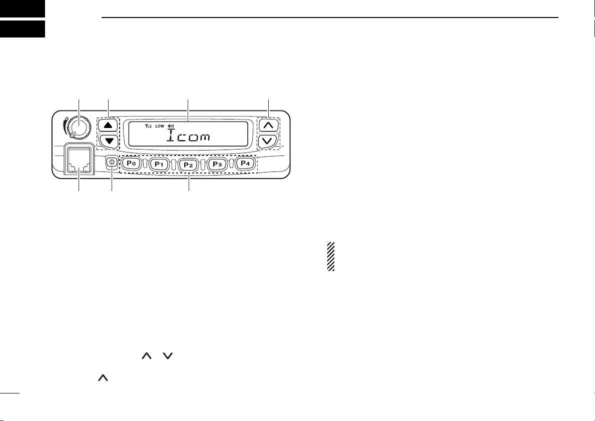
■ Front panel
q rew
u y t
q AF VOLUME CONTROL KNOB
Rotate the knob to adjust the audio output level.
• Minimum audio level is pre-programmed.
w LEFT UP/DOWN [∫∫]/[√√] KEYS
Push to select the talk group on the LTR or PassPort system.
e FUNCTION DISPLAY
Displays a variety of information, such as an operating
channel text, talk group text.
NOTE: The above functions depend on pre-programming.
r RIGHT UP/DOWN [ ]/[ ] KEYS
➥Push to select the operating system.
➥Push []key to send the most recently transmitted
DTMF code number during transmitting.
1
t DEALER-PROGRAMMABLE KEYS [P0] to [P4]
Desired functions can be programmed independently by
your dealer.
y POWER SWITCH [POWER]
Push to turn the power ON and OFF.
• At power ON, a power-up alert tone sounds for about 1 sec. and
an opening message may appear. And the transceiver automatically starts scanning if the scan function had been activated
before the power was turned OFF.
u MICROPHONE CONNECTOR
Connect the supplied microphone or optional DTMF microphone.
NEVER connect non-specified microphones. The pin
assignments may be different and the transceiver may
be damaged.
DD
MICROPHONE
The supplied microphone has a PTT switch and a hanger
hook.
Page 5
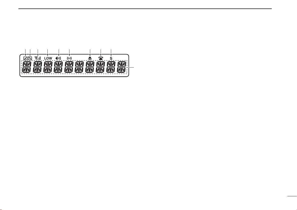
■ Function display
q w e r t y u i o
!0
q TRANSMIT INDICATOR
Appears while transmitting.
PANEL DESCRIPTION
u BELL INDICATOR
Blinks when the individual call is received.
i PHONE INDICATOR
Appears when the phone channel is selected.
o SCAN INDICATOR
Appears when the scan function is set in the channel, and
blinks while scanning.
1
w BUSY INDICATOR
Appears while the channel is busy.
e SIGNAL STRENGTH INDICATOR
➥Indicates relative signal strength level.
➥Does not appear when the transceiver is out of the ser-
vice area when operating on the PassPort system.
r LOW POWER INDICATOR
Appears when low output power is selected.
t MONITOR SWITCH INDICATOR
Appears when the monitor switch is pushed.
y COMPANDER INDICATOR
Appears when the compander function is activated.
!0 ALPHANUMERIC DISPLAY
Displays an operating channel text, talk group text, etc.
2
Page 6

2
CONNECTION AND MAINTENANCE
■ Rear panel and connection
Optional speaker
(SP-22)
Optional cable
r
(OPC-617)
t
Antenna
e
w
Supplied DC
power cable
black:
Note: Use the
terminals for the
cable connections.
Crimp
q
red:
12V
Battery
NEVER connect to
+
a 24 V battery.
Solder
3
Page 7

CONNECTION AND MAINTENANCE
qw
e
r
t
y
u
i
o
!0 !1 !2
!3
LCD-STICKER
IC
OM
2
q MICROPHONE HANGER
Connect the supplied microphone hanger to the vehicle’s
ground.
w ANTENNA CONNECTOR
Connects to an antenna. Ask your dealer about antenna
selection and placement.
e DC POWER RECEPTACLE
Connects to a 12 V DC battery. Pay attention to polarities.
NEVER connect to a 24 V battery. This could damage the
transceiver.
r OPTIONAL CABLE (OPC-617)
Connect an external modem unit, LCD backlight control,
etc.
t EXTERNAL SPEAKER JACK
Connect a 4–8 Ω external speaker, if desired.
■ Supplied Accessories
q Microphone ...................... 1
w Microphone hanger and
screw set ..................... 1 set
e Microphone hanger cable . 1
r DC power cable ................. 1
(OPC-345 : IC-F610/F620,
OPC-1132: IC-F621)
t Mounting bracket .............. 1
y Bracket bolts ..................... 4
u Mounting screws (M5×12) . 4
*Function name stickers
There are no names on the programmable function keys since the
needed functions can be assigned to these keys.
Attach the supplied function name stickers above the appropriate
keys.
i Self-tapping screws
(M5×20) ............................. 4
o Flat washers ...................... 4
!0 Spring washers ................. 4
!1 Nuts ................................... 4
!2 Fuses ................................ 2
(15 A: IC-F610/F620,
20 A: IC-F621)
!3 Function name stickers*
(1705 LCD SEAL(H)) ................1
4
Page 8

CONNECTION AND MAINTENANCE
normal bend line
inverted
bend line
Flat cable orientation
to front panel
to main unit
2
■ Mounting the transceiver
The front panel can be inverted for correct viewing while leaving the built-in speaker facing away from the mounting surface.
D Inverting the front panel
q Unscrew the 2-side screws.
w Detach the front panel forward from the transceiver.
e Bend the flat cable between front panel and main unit as
shown in the following diagram.
r Invert the transceiver 180 degrees clockwise as below.
t Re-attach the front panel to the transceiver.
y Tighten the 2 screws.
CAUTION:
• NEVER rotate the transceiver more than 180
degrees.
• DO NOT bend the flat cable too hard. Damage may
occur.
• Be sure to bend the flat cable in the correct direction, before turning over (inverting) the transceiver.
5
Page 9

D Mounting the transceiver
Flat washer
Spring washer
When using
self-tapping screws
The universal mounting bracket supplied with your transceiver allows overhead mounting.
• Mount the transceiver securely with the 4 supplied screws
to a thick surface which can support more than 1.5 kg.
CONNECTION AND MAINTENANCE
2
6
Page 10

CONNECTION AND MAINTENANCE
B
2
■ Optional UT-109/UT-110 installation
Install the optional UT-109 and UT-110 as shown below:
q Turn power OFF, then disconnect the DC power cable.
w Unscrew the 4 screws, then remove the bottom cover.
e Remove the unit pre-installed at the factory.
r Cut the print pattern on the PCB at the TX mic circuit (A)
and RX AF circuit (B) as shown below.
Front panel
t Install the scrambler unit.
y Replace the bottom cover and screws, then the DC power
cable.
NOTE: Be sure to re-solder
the disconnected points at
left, otherwise no TX modulation or AF output is available when you remove the
scrambler units.
7
Page 11

CONNECTION AND MAINTENANCE
OPTIONAL CABLE PIN ASSIGNMENT
t r e w q
o
i u y
q
LCD backlit cont. IN
w AF OUT
e Det. AF OUT
r Mod. IN
t PTT control IN
y Horn drive cont. OUT
u AF GND
i Det. AF GND
o Mod. GND
2
■ Optional OPC-617 installation
Install the OPC-617 as shown below.
■ Antenna
A key element in the performance of any communication system is an antenna. Ask your dealer about antennas and the
best places to mount them.
■ Fuse replacement
Two fuses are installed in the supplied DC power cable. If a
fuse blows or the transceiver stops functioning, track down
the source of the problem if possible, and replace the damaged fuse with a new rated one.
❑ Fuse rating : 15 A (IC-F610/F620), 20 A (IC-F621)
■ Cleaning
If the transceiver becomes dusty or dirty, wipe it clean with a
dry, soft cloth.
AVOID the use of solvents such as benzene or
alcohol, as they may damage transceiver surfaces.
8
Page 12

CONNECTION AND MAINTENANCE
2
■ Options
SP-22
EXTERNAL SPEAKER
OPC-617
HM-100TN
ACC CABLE
DTMF MICROPHONE
Compact and easy-to-install.
Input impedance: 4 Ω
Max. input power: 5 W
Allows you to connect to an external terminal.
Hand microphone with a DTMF
keypad.
SM-25
DESKTOP MICROPHONE
UT-109/UT-110 (#02)
UT-109 UT-110
For base station operation.
Monitor switch is equipped.
VOICE SCRAMBLER UNIT
• UT-109: Non-rolling type
(max. 32 codes)
• UT-110: Rolling type
(max. 1020 codes)
9
Page 13

SAFETY TRAINING INFORMATION
WARNING
CAUTION
3
Your Icom radio generates RF electromagnetic energy during transmit mode. This
radio is designed for and classified as
“Occupational Use Only”, meaning it must
be used only during the course of employ-
ment by individuals aware of the hazards,
and the ways to minimize such hazards. This radio is
NOT intended for use by the “General Population” in an
uncontrolled environment.
• For compliance with FCC and Industry Canada RF
Exposure Requirements, the transmitter antenna installation
shall comply with the following two conditions:
1. The transmitter antenna gain shall not exceed 0 dBi.
2. IC-F620:
The transmitter antenna is required to be located outside
of a vehicle and kept at a separation distance of 37 centimeters or more between the transmitter antenna of this
device and persons during operation.
2. IC-F621:
The transmitter antenna is required to be located outside
of a vehicle and kept at a separation distance of 50 centimeters or more between the transmitter antenna of this
device and persons during operation.
To ensure that your exposure to RF electromagnetic energy is within the FCC
allowable limits for occupational use,
always adhere to the following guidelines:
• DO NOT operate the radio without a proper antenna
attached, as this may damage the radio and may also cause
you to exceed FCC RF exposure limits. A proper antenna is
the antenna supplied with this radio by the manufacturer or
an antenna specifically authorized by the manufacturer for
use with this radio.
• DO NOT transmit for more than 50% of total radio use time
(
“
50% duty cycle”). Transmitting more than 50% of the time
can cause FCC RF exposure compliance requirements to
be exceeded. The radio is transmitting when the “TX indicator” lights red. You can cause the radio to transmit by pressing the “PTT” switch.
Electromagnetic Interference/Compatibility
During transmissions, your Icom radio generates RF energy
that can possibly cause interference with other devices or
systems. To avoid such interference, turn off the radio in
areas where signs are posted to do so. DO NOT operate the
transmitter in areas that are sensitive to electromagnetic radiation such as hospitals, aircraft, and blasting sites.
10
Page 14

MEMO
Page 15

MEMO
Page 16

A-6243H-1EX-w
Printed in Japan
© 2002–2004 Icom Inc.
1-1-32 Kamiminami, Hirano-ku, Osaka 547-0003, Japan
 Loading...