

Page 1
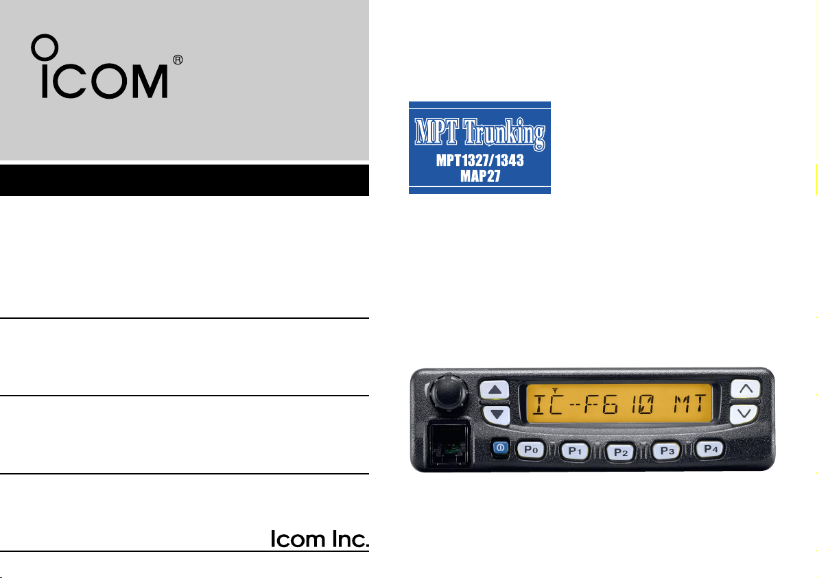
INSTRUCTION MANUAL
UHF TRUNKED RADIO
iF610
Page 2

Icom, Icom Inc. and the logo are registered trademarks of
Icom Incorporated (Japan) in the United states, the United
Kingdom, Germany, France, Spain, Russia and/or other countries.
Page 3

FOREWORD
IMPORTANT
Thank you for purchasing this Icom product.
IC-F610 UHF TRUNKED RADIO is designed and built with
Icom’s superior technology and craftsmanship. With proper
care, this product should provide you with years of troublefree operation.
We want to take a couple of moments of your time to thank
you for making the IC-F610 your radio of choice, and hope
you agree with Icom’s philosophy of “technology first.” Many
hours of research and development went into the design of
your IC-F610.
ïï
FEATURES
❍
Compatible with MPT 1327/1343 Networks
❍
Short Data Message (SDM)
❍
32 Status Messages Capability
❍
MAP27 Data Communication Protocol, RS-
232C PC Interface
❍
Optional Voice Scrambler Unit, UT-109/UT-110
❍
Flash ROM CPU, Firmware Upgrade Capabil-
ity
❍
Keypad microphone (HM-100TN) Available
READ ALL INSTRUCTIONS carefully and complete-
ly before using the transceiver.
SAVE THIS INSTRUCTION MANUAL — This
instruction manual contains important operating instructions for
the IC-F610 UHF TRUNKED RADIO.
EXPLICIT DEFINITIONS
WORD DEFINITION
R WARNING
CAUTION
NOTE
Personal injury, fire hazard or electric shock
may occur.
Equipment damage may occur.
If disregarded, inconvenience only. No risk
of personal injury, fire or electric shock.
i
Page 4

CAUTIONS
R WARNING! NEVER connect the transceiver to an
AC outlet. This may pose a fire hazard or result in an electric
shock.
NEVER connect the transceiver to a power source of more
than 16 V DC such as a 24 V battery. This connection will ruin
the transceiver.
NEVER cut the DC power cable between the DC plug and
fuse holder. If an incorrect connection is made after cutting,
the transceiver might be damaged.
NEVER place the transceiver where normal operation of
the vehicle may be hindered or where it could cause bodily
injury.
NEVER allow children to touch the transceiver.
NEVER expose the transceiver to rain, snow or any liquids.
USE supplied microphone only. Other microphones have
different pin assignments and may damage the transceiver.
DO NOT use or place the transceiver in areas with tem-
peratures below –22°F (–30°C) or above +140°F (+60°C) or,
in areas subject to direct sunlight, such as the dashboard.
AVOID operating the transceiver without running the vehi-
cle’s engine. The vehicle’s battery will quickly run out if the
transceiver is in transmission while the vehicle’s engine OFF.
AVOID placing the transceiver in excessively dusty envi-
ronments.
AVOID placing the transceiver against walls. This will
obstruct heat dissipation.
AVOID the use of chemical agents such as benzine or
alcohol when cleaning, as they damage the transceiver surfaces.
BE CAREFUL! The transceiver will become hot when
operating continuously for long periods.
ii
Page 5

TABLE OF CONTENTS
FOREWORD . . . . . . . . . . . . . . . . . . . . . . . . . . . i
IMPORTANT . . . . . . . . . . . . . . . . . . . . . . . . . . . . i
EXPLICIT DEFINITIONS . . . . . . . . . . . . . . . . . . i
CAUTIONS . . . . . . . . . . . . . . . . . . . . . . . . . . . . ii
TABLE OF CONTENTS . . . . . . . . . . . . . . . . . . iii
1 PANEL DESCRIPTION . . . . . . . . . . . . . . . 1–4
■Front panel . . . . . . . . . . . . . . . . . . . . . . . . . 1
■Programmable key assignment . . . . . . . . . 3
■Function display . . . . . . . . . . . . . . . . . . . . . 4
2 OPERATION . . . . . . . . . . . . . . . . . . . . . . 5–12
■Turning power ON . . . . . . . . . . . . . . . . . . . 5
■General . . . . . . . . . . . . . . . . . . . . . . . . . . . . 6
D Opening text . . . . . . . . . . . . . . . . . . . . . . . . 6
■Calling . . . . . . . . . . . . . . . . . . . . . . . . . . . . 6
D Making a call with a memory Dial Number . 6
DMaking a call with a memory Individual Code . . 7
D Calling the Dispatcher . . . . . . . . . . . . . . . . . 7
D Making a Status Call . . . . . . . . . . . . . . . . . . 8
DSending a status message to the Despatcher . 8
D Include Call . . . . . . . . . . . . . . . . . . . . . . . . . 9
D PTT Quick Call function . . . . . . . . . . . . . . . 9
■Making a call via the keypad . . . . . . . . . . . 9
D Individual Call . . . . . . . . . . . . . . . . . . . . . . . 9
D Group Call . . . . . . . . . . . . . . . . . . . . . . . . 10
D Status Call . . . . . . . . . . . . . . . . . . . . . . . . 10
D Enhanced Group Call . . . . . . . . . . . . . . . . 10
D Priority Call . . . . . . . . . . . . . . . . . . . . . . . . 10
D Emergency Call . . . . . . . . . . . . . . . . . . . . 11
D System Wide Call . . . . . . . . . . . . . . . . . . . 11
D PSTN Call . . . . . . . . . . . . . . . . . . . . . . . . 11
D PABX Call . . . . . . . . . . . . . . . . . . . . . . . . . 11
D Divert Own Call . . . . . . . . . . . . . . . . . . . . 11
D Divert 3rd Party Call . . . . . . . . . . . . . . . . . 11
D Cancellation of Divert . . . . . . . . . . . . . . . . 11
D SDM (Short Data Message) Call . . . . . . . 12
D 5-Digit Routing code calling . . . . . . . . . . . 12
D Cancellation of calling . . . . . . . . . . . . . . . 12
D Cancellation of Input . . . . . . . . . . . . . . . . 12
■Special calling via the keypad . . . . . . . . . 12
D ReDial . . . . . . . . . . . . . . . . . . . . . . . . . . . 12
D Short Dialing . . . . . . . . . . . . . . . . . . . . . . 12
3 RECEIVING . . . . . . . . . . . . . . . . . . . . . 13–15
■Receiving a call . . . . . . . . . . . . . . . . . . . . 13
D Reception of an individual Call . . . . . . . . . 13
D Reception of a Group Call . . . . . . . . . . . . 13
D Reception of a Status Call . . . . . . . . . . . . 14
DReception of a SDM (Short Data Message) Call . .
. . . . . . . . . . . . . . . . . . . . . . . . . . . . . . . . . . . .14
■Progress messages . . . . . . . . . . . . . . . . . 15
4 OTHER FUNCTION . . . . . . . . . . . . . . . 16–18
D Call Back function . . . . . . . . . . . . . . . . . . 16
D DTMF function . . . . . . . . . . . . . . . . . . . . . 16
D Scrambler function . . . . . . . . . . . . . . . . . . 17
D Compander function . . . . . . . . . . . . . . . . . 17
D Mic Hook OFF function . . . . . . . . . . . . . . 17
D Mic Hook ON function . . . . . . . . . . . . . . . 17
D Horn Honk function . . . . . . . . . . . . . . . . . 17
D Public Address function . . . . . . . . . . . . . . 17
D RX Speaker function . . . . . . . . . . . . . . . . 18
D Ignition SW function . . . . . . . . . . . . . . . . . 18
D Auto Talk Around function . . . . . . . . . . . . 18
5 USER SETUP MENU . . . . . . . . . . . . . . . . . . 19
■User Setup Menu . . . . . . . . . . . . . . . . . . . 19
D Selectable items and setting value . . . . . 19
6 MAP27 . . . . . . . . . . . . . . . . . . . . . . . . . . . . . 20
■MAP27 serial interface . . . . . . . . . . . . . . . 20
7 CONVENTIONAL MODE . . . . . . . . . . . . 21–22
■Conventional mode operation . . . . . . . . . . 21
■Programmable key assignment . . . . . . . . . 21
8 CONNECTION AND MAINTENANCE . . 23–27
■Rear panel and connection . . . . . . . . . . . 23
■Supplied Accessories . . . . . . . . . . . . . . . . 24
■Mounting the transceiver . . . . . . . . . . . . . . 25
D Inverting the Front panel . . . . . . . . . . . . . 25
D Mounting the transceiver . . . . . . . . . . . . . 26
■Optional UT-109/UT-110 installation . . . . . 26
■Optional OPC-617 installation . . . . . . . . . . 27
■Antenna . . . . . . . . . . . . . . . . . . . . . . . . . . . 27
■Fuse replacement . . . . . . . . . . . . . . . . . . . 27
■Cleaning . . . . . . . . . . . . . . . . . . . . . . . . . . 27
9 CLONING . . . . . . . . . . . . . . . . . . . . . . . . . . . 28
10OPTIONS . . . . . . . . . . . . . . . . . . . . . . . . . . 29
CE . . . . . . . . . . . . . . . . . . . . . . . . . . . . . .30
iii
Page 6
1
!2
!1
i
r
e
w
q
!0 o u y
t
PANEL DESCRIPTION
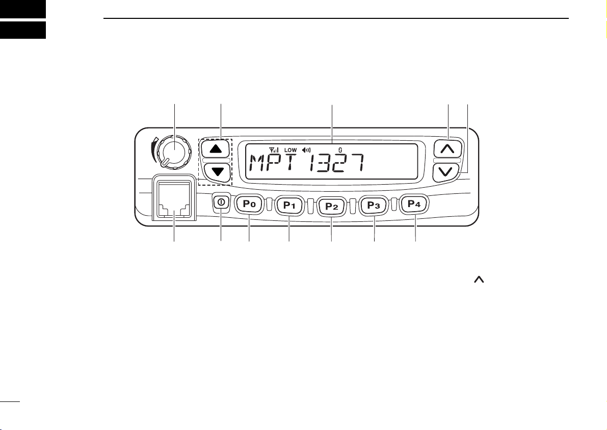
■ Front panel
q AF VOLUME CONTROL KNOB
Rotate the knob to adjust the audio output level.
• Minimum audio level is pre-programmed.
w STATUS UP/DOWN (LEFT UP/DOWN) KEYS* [∫∫]/[√√]
Pushing these keys will scroll up/down the status memory.
e FUNCTION DISPLAY
Displays a variety of information, such as dialling numbers,
texts, status and message, etc.
1
r MEMORY UP (RIGHT UP) KEY* [ ]
➥ Pushing the key will scroll up to the next stored code.
➥ If the stored calls are displayed by pushing the Call Back
key, this key scrolls up the screen.
➥ While entering the dial number via the optional microphone
keypad, push the key to delete the last digit as a backspace key.
Page 7

PANEL DESCRIPTION
1
t MEMORY DOWN (RIGHT DOWN) KEY* [ ]
➥If the stored calls are displayed by pushing the Call Back
key, this key scrolls down the screen.
➥While entering the dial number via the optional microphone
keypad, push the key to delete the last digit as a backspace
key.
y CLEAR KEY* [Clear/P
4]
➥If this key is pushed during a call, the call is finished.
➥If the key is push and held down for 2.5 sec., the User
Setup Menu appears (or the user setup menu is cancelled).
➥Pushing the key to cancel any keypad operation, and return
to normal mode.
u CALL BACK KEY* [Call Back/P
3]
➥Pushing this key will display the stored calls that you have
not answered yet.
➥Pushing the key again will return to the standby mode.
➥Push and hold the key for 2.5 sec., the Call Back mode
turns ON or OFF. While the Call Back mode is turned ON,
received calls are stored in the LOG, then the Call Back
message is automatically sent back to the called station.
i MODE KEY* [Mode/P
2]
Push to toggle the mode between MPT and convention.
Emergency Function; p. 11).
!0 DESPATCHER KEY* [Despatcher/P
0]
➥Pushing the key will display the screen in the Despatcher
mode.
➥Pushing the key again will display a status code (if permit-
ted by the settings).
➥Pushing the key again will go to the standby mode.
!1 POWER SWITCH [POWER]
Push to turn the power ON and OFF.
• The following functions are available at power ON as options:
- Password prompt
!2MICROPHONE CONNECTOR
Connect the supplied microphone, or optional DTMF microphone for dialing operation via the keypad.
MICROPHONE
The supplied microphone has a PTT switch and a hanger
hook.
• The following functions are available when the microphone is on or off hook:
- hook off: Answer
- hook on: Clear Down
o EMERGENCY KEY* [Emergency/P
1]
Push and hold for 2.5 sec. to initiate an Emergency Call(✱9)
to the pre-determined station or current station (Selectable
*Programmable function keys and default key assignment.
2
Page 8

PANEL DESCRIPTION
1
‘‘
Programmable key assignment
Dealer programmable keys [P0], [P1], [P2], [P3], left Up/Down
[∫∫]/[√√] and right Up/Down [ ]/[ ] can be programmed for
one of several functions by your Icom dealer.
In the following explanations, programmable function names
are bracketed; the specific switch used to activate the function depends on programming.
Trunking mode only:
[Despatcher]([P0])*
The exclusive key used to call the despatcher.
[Call1], [Call2]
The exclusive key used to call the pre-programmed station.
[Emergency]([P
The exclusive key used to call the pre-programmed
Emergency station.
[Clear]([P
Push this key to clear down the communication.
Push and hold the key for 2.5 seconds when your transceiver is in the standby mode (not during communication,
dialling or operation), the User Setup Menu (p. 19)
appears.
1])*
4])*
[Call Back]
Push this key to turn the Call Back function ON or OFF.
Press the key will display the stored calls that you have
not yet answered.[Status Up] [Status Down]([∫∫]/[√√])*
This key is used to select the status memory.
[Memory Up] [memory Down]([ ]/[ ])*
This key is used to select the Memory channel.
*Default key assignments.
Either Trunking or Conventional mode;
[Mode]
Push the key to toggles between Trunking mode and
Conventional mode.
[Null]
No function is assigned.
[High/Low]
Pushing the key will toggle in the order of Low1 power,
Low2 power, High power and Auto power.
[Public Address]
Use the transceiver as an audio amplifier.
[RX Speaker]
Output the receive audio to an out-of-vehicle speaker.
3
Page 9
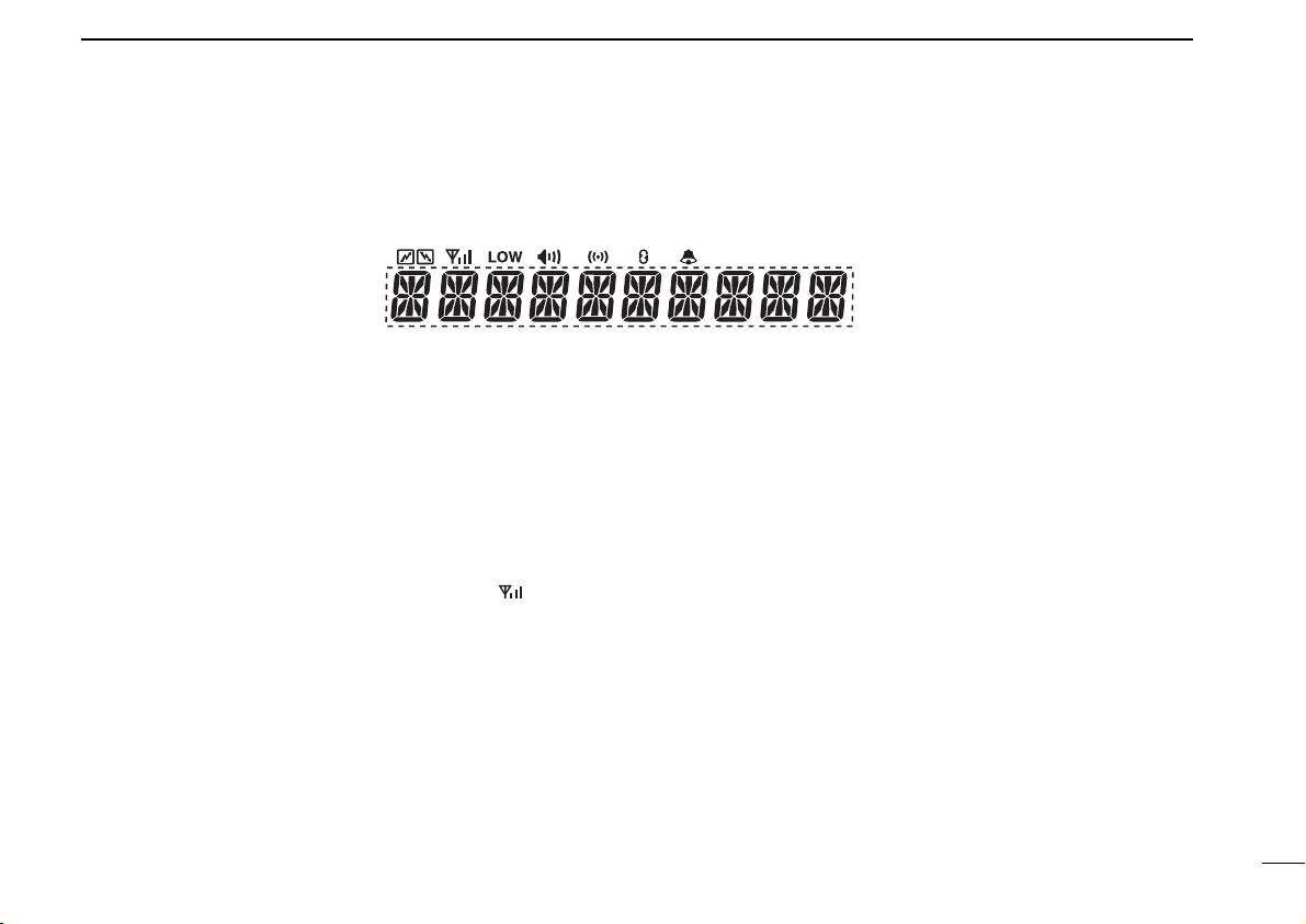
■ Function display
q w e r t y u i
o
PANEL DESCRIPTION
1
q TRANSMIT INDICATOR
Appears while transmitting.
w RECEIVE INDICATOR
Appears while receiving a message.
e SIGNAL STRENGTH METER
Indicates the received signal strength at 4 levels.
•If the connection with the communication network is not
established, the whole icon turns OFF while blinks.
•For a stable communication, at least the second highest
level (with two bars appearing) is required.
r LOW POWER INDICATOR
Appears if the transmission output is set to a low power level
(Low1 or Low2). Does not appear when High power is selected.
t SPEAKER INDICATOR
Appears when voice communication becomes possible.
y COMPANDER INDICATOR
Appears when the compander function that improves the
communication quality, is activated.
u SCRAMBLER INDICATOR
Appears when the scrambler is activated.
i CALL BACK INDICATOR
Blinks if any call number to which you have not yet answered
is stored.
o ALPHANUMERIC DISPLAY
Indicates personal ID, opening text, etc., according to operating condition.
4
Page 10

2
OPERATION
■ Turning power ON
q Push to turn the power ON.
• A power-up alert tone sounds for about 1 sec. and an
opening message may appear.
w If the transceiver is programmed for a start up passcode,
input the digit codes as directed by your dealer.
• The keys in the table below can be used for password
input.
• The transceiver detects numbers in the same block as
identical. Therefore “01234” and “56789” are the same.
e When the “PASSWORD” indication does not clear after
inputting digit codes, the input code number may be incorrect. Turn the power off and start over in this case.
KEY [P0][P1][P2][P3][P4]
NUMBER 0 1 2 3 4
56789
5
Page 11
OPERATION
2
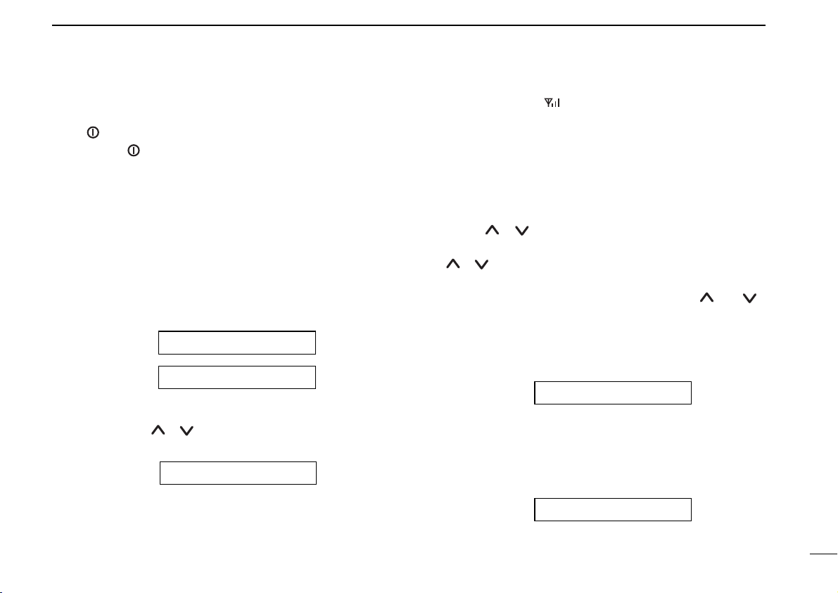
‘‘
General
Push to turn the power ON. A power-up alert tone will be
heard. Push again to turn the power OFF. The following
information will sequentially appear on the display.
DD
Opening text
The pre-programmed opening text and individual ID will
appear.
The individual ID consisting of a prefix code (3 digits) + a
fleet code (2 digits)+ an individual code (2 or 3 digits) will
appear.
(e.g.) If the prefix code is 200, the fleet code 2001, and the
individual code 300, the individual ID will be ‘2002001300’.
(OPENING TEXT)
201 2001 300
• If you are within the trunking service area, the code
(selected by [ ]/[ ]) and the received signal strength,
are displayed to indicate that communication is possible.
-TEXT-
*In the “-TEXT-” part, the characters pre-programmed by
cloning software will be displayed.
system is down, will blink.
At this time, the transceiver is searching for any available
system-controlled channel.
‘‘
Calling
DD
Making a call with a memory Dial Number
Using [ ]/[ ], select one of the group codes that is
stored in the memory.
[ ]/[ ] allows you to select any group code from the 40
dial numbers.
q Select the desired dial number by pushing [ ] or [ ].
w Push [PTT] to make a call with the selected dial num-
ber.
e With ‘Calling’ displayed, the intermittent beep sound for
calling will be heard.
CALLING
r With ‘Connected’ displayed, the speaker icon will appear
allowing you to start the communication. At the same
time, the count-down timer will appear to limit the communication time.
CONNECTED
• If you are outside of the trunking service area, or if the
6
Page 12

OPERATION
2
t A warning beep will be emitted 10 seconds before the
communication timer reaches the limit. When the limit
has been reached, the communication will be disconnected automatically.
TIME 1 59
y To manually end the communication, push [Clear]. (or
push [✱], then push [#]).
CLEAR DOWN
DD
Making a call with a Memory Individual Code
Push [ ]/[ ] to select a memory individual code to make
the call.
q Display an individual code by push [ ]/[ ].
w Select the desired individual code using [ ]/[ ].
PERSONAL 1
e Push [PTT] to start calling with the selected individual
code.
r While ‘Calling’ is displayed, the intermittent beep sound
for calling will be heard.
t With ‘Connected’ displayed, will appear allowing you
to start the communication. At the same time, the countdown timer will appear to limit the communication time.
y A warning sound will be emitted 10 seconds before the
7
communication timer reaches the limit. When the limit
has been reached, the communication will be disconnected automatically.
u To manually end the communication, press the [Clear]
key. (or push [✱], then push [#]).
DD
Calling the Dispatcher
The despatcher may be called directly.
q Press the [Dispatcher] key.
DESPATCHER
w Press the [PTT] key. The call to the dispatcher will be
started.
NOTE: If calling direct to the Despatcher is prohibited, the
status message 00 (or 0) (Call Back Request) is
transmitted and then the the transceiver will return to
the waiting mode.
e While ‘Calling’ is displayed, the intermittent beep sound
will be heard.
r With ‘Connected’ is displayed, will appear allowing
you to start the communication. At the same time, the
countdown timer will appear to limit the communication
time.
Page 13

OPERATION
2
t A warning sound will be emitted 10 seconds before the
communication timer reaches the limit. When the limit
has been reached, the communication will be disconnected automatically.
y Push [Clear] to manually end the communication.
DD
Making a Status Call
A status message may be sent to the dispatcher or a
remote station having an individual code. (No status message can be sent to any station using a group code.)
•Sending a status message to a station having an individual
code.
q Display an individual code by pushing [ ]/[ ].
PERSONAL 1
w Press the Status Up [∫]/Down [√] to enter the status
code select mode.
STATUS 01
➥ Select the desired message from a total of 32 differ-
ent status messages having code No. 0 through 31.
➥ Status code 0 means “Call Back Request” -- Please
call back, and status code 31 “Previous Request
Cancel” -- Cancels the call. These status codes are
commonly used by all systems.
e Press [PTT], the status message will be sent to the sta-
tion having the selected individual code.
r When the status message has been successfully sent
out, ‘OK’ appears on the display.
DD
Sending a status message to the Despatcher
q Enter the Despatcher mode by pushing the [Despatcher ].
DESPATCHER
w Press [Despatcher] again. Now you are ready to select
a status code.
STATUS 01
➥ If the direct call to the despatcher is selected, you
cannot use status code select condition.
e Push [∫]/[√] to select the desired status message.
➥ Select the desired message from a total of 32 differ-
ent status messages having code No. 0 through 31.
➥ Status code 0 means “Call Back Request” -- Please
call back, and status code 31 “Previous Request
Cancel” -- Cancels the call. These status codes are
commonly used by all systems.
8
Page 14

OPERATION
2
r Push [PTT] to send the status message to the despatch-
er.
t When the status message has been successfully sent
out, ‘OK’ appears on the display.
DD
Include Call
•After moving to the communication channel, you can
make an additional call to the other station for them join
in to the communication with you.
➥Make a call with a memory individual/group call or make
a call via the keypad on the communication channel to
start the Include call.
DD
PTT Quick Call function
The Despatcher, Status message, Call Back memory
selected by function key or the currently selected memory
group (current group) can be called only by push [PTT].
■ Making a call via the keypad
Various calls can be made by the following keying sequences
via the keypad*.
*HM-100TN optional DTMF microphone is required.
**Turn the ‘DTMF Mic’ function in the ‘Common-Common’
menu of the cloning software to ‘Enable’ when using this
function. Please consult your dealer.
DD
Individual Call;
• Individual call to a station having the same prefix and
fleet codes.
Enter an individual code via the keypad and then push [#].
The individual call will be started.
(e.g.) To call 200 2001 300 from 200 2001 200, enter
‘300#’.
• Individual Call to a station having the same prefix code
and a different fleet code.
Enter the fleet code plus the individual code via the keypad and then push [#]. The individual call will be started.
(e.g.) To call 200 2006 300 from 200 2001 200, enter
2006300#.
• Individual Call to a station having a different prefix
code.
Enter the prefix code plus the fleet code plus the individual
code via the keypad and then push [#]. The individual call
will be started.
(e.g.) To call 211 2006 300 from 200 2001 200, enter
2112006300#.
NOTE: Instead of pushing [#], push [PTT] can be also make
the call.
9
Page 15

OPERATION
2
DD
Group Call
•Group Call to the stations having the same prefix and
fleet codes.
Enter the group code via the keypad and then push [#].
The group call will be started.
(e.g.) To call 200 5001 91 from 200 2001 200, enter 91#.
• Group Call to the stations having the same prefix code
and a different fleet code.
Enter the fleet code plus the group code via the keypad
and then push [#]. The group call will be started.
(e.g.) To call 200 6002 90 from 200 2001 200, enter
600290#.
• Group Call to the stations having a different prefix code.
Enter the prefix code plus the fleet code plus the group
code via the keypad and then push [#]. The group call will
be started.
(e.g.) To call 211 6002 90 from 200 2001 200, enter
211600290#.
DD
Status Call
•Enter ✱0xx (xx: a status code in the range between 00
and 31) and then push [#]. The status call to the despatcher will be started.
(e.g.) To send status code 02 to 200 2001 300 from 200
2001 200, enter ✱002✱300#. You can omit the first
“0” between status 00 and 09, for example as
✱02✱300#.
•To make the Call Back request of the status call to the
despatcher, enter ✱0#.
•To make the cancellation of the above request to the
despatcher, enter #0#.
•To make the Call Back request of the status call to the
individual code station, enter ✱0✱ plus an individual code
plus [#].
•To make the cancellation of the above request to the individual code station, enter #0✱ plus an individual code plus [#].
DD
Enhanced Group Call
• To make a Conference Call;
Enter ✱1✱ plus a group code and then push [#]. The conference call will be started allowing the called stations to
have communication.
• To make a Broadcast Call;
Enter ✱11 ✱ plus a group code and then push [#]. The
broadcast call will be started allowing the called stations
only to listen to the call.
DD
Priority Call
•Enter ✱8✱ plus an individual call/a Group call and so on,
then push [#]. The priority call will be started.
➥If the system is busy (no channel is available), the pri-
ority is given on a first-come-first-served basis.
10
Page 16

OPERATION
2
DD
Emergency Call
• Enter ✱9✱ plus an individual code or a group code and
then push [#]. The emergency call will be started.
‘Selectable Emergency Function; Disable*’
➥Enter ✱9, then push [#]. The pre-programmed
‘Emergency Number’ used for the emergency call.
‘Selectable Emergency Function; Enable*’
➥Enter ✱9, then push [#]. The current ‘Dial Number’
selected via [ ]/[ ] used for the emergency call.
-If the system is busy (no channel is available), a channel is forcibly made available allowing you to establish
the communication.
‘
Selectable Emergency Function’ can be set with the cloning software
(p. 28).
DD
System Wide Call
• Entering ✱1981# will allow you to make a priority voice
call.
• Entering ✱1982# will allow you to make a voice call.
• Entering ✱1987# will allow you to make a standard voice
call.
➥Each of the above calls is used to call all the mobile sta-
tions that are waiting on the system.
DD
PSTN Call
Enter 0 plus a telephone number (8 digits or more) and
then push [#]. The PSTN call will be started.
DD
PABX Call
Enter 0 plus a telephone number (5 to 7 digits) and then
push [#]. The PABX call will be started.
DD
Divert Own Call
• Enter ✱41n✱ plus the individual code of the station you
want to divert your own call to, and then push [#].
This will allow you to divert your own call to the specified
station.
➥In the place of ‘n’, enter 1 for voice, 0 for data, or noth-
ing for both voice and data.
• Enter #41n✱, then push [#] to cancel the diversion.Or
enter #45n# to cancel the above diversion on the station
you want to divert your own call to.
DD
Divert 3rd Party Call
• Enter ✱44n✱ plus Station B’s individual code plus ✱ plus
Station A’s individual code (destination), and then push
[#]. Station B’s call will be diverted to Station A.
➥In the place of ‘n’, enter 1 for voice, 0 for data, or noth-
ing for both voice and data.
• Enter #44n✱ plus station B’s individual code, and then
push [#] to cancel this diverting.
DD
Cancellation of Divert
• Enter #41n and then push [#]. This will allow you to cancel the Divert Own call.
11
Page 17

OPERATION
2
• Enter #44n✱ plus station B’s individual code and then
push [#]. This will allow you to cancel the Divert 3rd Party
call.
• Enter #45n and then push [#]. This will allow you to cancel the call that diverted to you.
➥In the place of ‘n’, enter 1 for voice, 0 for data, or noth-
ing for both voice and data.
DD
SDM (Short Data Message) Call
• Enter ✱2✱ plus data (up to 24 digits in total) via the keypad and then push [#]. This will allow you to make a data
call to a predetermined station.
• Enter ✱2✱ plus data via the keypad plus individual code
(up to 24 digits in total) and then push [#]. This will allow
you to make a data call to an individual code station.
DD
5-Digit Routing code calling
Converting a prefix code (3 digits) plus a fleet code (4 digits) to 3 digits allows you to dial a different prefix code and
fleet code by 5 digit dialling.
➥ Convertible numbers; 200 to 299, 900 to 999, 20 to 29, 90
to 99.
*Pre-program the prefix and fleet numbers before converting.
• Individual calling with different prefix code.
To call 211 2006 300 from 200 2001 200;
➥ Pre-program 22 to prefix code 211 and fleet code 2006
as 5-Digit Routing code. Enter 22300# to start the call.
DD
Cancellation of calling
Enter ✱ and then push [#]. This will allow you to cancel the
current call.
➥ This will allow you to end the communication or cancel
the current call.
DD
Cancellation of Input
When you are entering data via the keypad, push [ ]/[ ].
This will delete the data starting with the last character/digit
entered, allowing you to restart entering the data again.
Push [Clear] to cancel the inputting and return to the waiting mode.
‘‘
Special calling via the keypad
DD
ReDial
Enter ## via the keypad. This will allow you to redial the
last number called.
DD
Short Dialling
Enter # followed by the memory location (1 to 9). This
allows you to automatically dial a commonly used number
from memory 1 to 9 by pushing [ ]/[ ].
12
Page 18

3
RECEIVING
13
‘‘
Receiving a call
DD
Reception of an individual call
When an individual call is received, the telephone beep
sounds telling you that a call has been received.
Immediately after this, you can talk with the caller.
ALERTING
302
q The caller’s individual code and count-down timer will
appear on the LCD screen.
TIME 4 56
➥If the call is from a telephone (PSTN call) or PABX
(PABX call) will be displayed.
ALERTING
TELEPHONE PABX
w Pushing [PTT] will allow you to talk with the caller. The
transmission indicator will appear on the LCD.
e During the communication, the timer will count the com-
munication time. When the limit has been reached, the
communication will be automatically shut down (clear
down).
*Message and
individual code
displayed alternately.
ALERTING
r To end the communication manually, push [Clear] or
push [✱] then [#].
t The transceiver will return to the waiting mode.
• If you do not answer the call;
y If you did not answer the call by not push [PTT], the
caller’s number is stored in the Call Back memory. Up
to 15 non-answered calls are stored. If there is any nonanswered call remaining in the memory, the Call Back
icon blinks.
u Select the Call Back memory by pushing [Call Back] and
[ ]/[ ], then push [PTT]. This will allow you to call the
stored unanswered call.
Q1 302
DD
Reception of a Group Call;
You can receive a group call with a pre-programmed group
code number or the group code that has been selected via
[ ]/[ ].
When a group call is received, the beep sound is emitted
and you immediately are able to communicate.
q The LCD screen displays the caller’s individual code.
GROUP 200
Page 19

RECEIVING
3
➥ In the case of a call received from the Inter-Prefix,
‘INTER-PFIX’ is displayed on the LCD screen.
➥The communication time timer will appear on the dis-
play.
TIME 00 56
w The individual ID will appear if ‘Display Pressel’ function
is enabled, and remain displayed during the current
communication.
e Pushing [PTT] will allow you to talk with the caller.
➥In the case of a group call, the communication only
can be cleared down from the caller’s side. The called
station cannot clear down the communication.
DD
Reception of a Status Call
When a status call is received, a beep sound is heard.
q The LCD screen displays the text corresponding to the
status number and the caller’s individual code.
STATUS 01
302
w These text and the individual numbers remain until
[Clear] is pushed.
e If you push [Clear] to cancel the displayed status call,
the transceiver returns to the waiting mode.
DD
Reception of a SDM (Short Data Message) Call
When the Short Data Message is received, a beep sound
is heard.
q The LCD screen displays the received data and the
caller’s individual code, and then the display blinks.
(DATA)
302
w Push [ ]/[ ] to display the following data when over
10 digits of data has been received.
e No transmission can be made until the displayed data
message is cancelled by pushing [Clear].
r If you push [Clear] to cancel the displayed short data
message, the transceiver returns to the waiting mode.
14
Page 20

RECEIVING
3
‘‘
Progress messages
The following messages appear corresponding to the
progress of the processing of a call.
15
MESSAGE DESCRIPTION
ABORTED . . . . . .Your call has been aborted (Wait for a
while and then make the call again).
CALLING . . . . . . .Your call is now being processed.
CALL BACK . . . . .Your call has been recorded at the
called station (Wait for a reply).
DIVERTED . . . . .Your call has been diverted to another
station.
ENGAGED . . . . . .The called station has not received your
call since the line is busy (Wait for a
while and then make the call again).
INVALID . . . . . . . .You have entered an invalid number.
NO REPLY . . . . . .Your call has not been answered.
QUEUED . . . . . . .Your call has been put in the waiting list
(Wait for a while until your call is con-
nected).
RINGING . . . . . . .The called station is now ringing.
SYS BUSY . . . . . .The system is so busy that no call is
accepted now (Wait for a while and
then make the call again).
MESSAGE DESCRIPTION
TIMEOUT . . . . . .The communication time limit has been
exceeded (The communication has
already been ended).
FAILED . . . . . . . .Your call has failed or your called num-
ber is not supported by the system.
CANCELLED . . . .Your call has been cancelled.
CONNECTED . . .Your call has been connected success-
fully.
SYS WIDE . . . . . .System Wide calls are accepted now.
TELEPHONE . . . .PSTN calls are accepted now.
PABX . . . . . . . . . .PABX calls are accepted now.
INTER-PFIX . . . . .Calls from stations having different pre-
fix codes are accepted now.
CLEAR DOWN . .End the communication.
Page 21

OTHER FUNCTION
4
DD
Call Back function
•If you do not want to answer the call immediately, use this
function.
➥Pushing [Call Back] will allow you to enable or disable
the function.
•When this function is enabled, the transceiver sends the
Call Back to the called station. “CALL BACK” will be displayed on the called station’s display, or, when you did not
answer the call or the called station has cleared down
before you answered the call while this function is disabled, the caller’s number is automatically retained in the
memory.
•Up to 15 non-answered calls will be stored.
•When a call is received, the caller’s number is automatically retained in the memory.
•At the same time, starts blinking to tell the user that
there is the non-answered call stored in the memory.
• will continue to blink until you have answered all the
non-answered calls, or until you have cleared the memory.
• When you push [Call Back] to confirm the memorized
contents, stops blinking.
•All the retained non-answered calls are cleared when the
power is turned OFF.
Even if the Call Back function is enabled, calls can be
made normally.
• Call Back
q If you push [Call Back] when the is blinking or lights,
the memory numbers are displayed.
w A memory number can be selected using [ ]/[ ].
e Select a number and then push [PTT]. The selected
number will be dialled to call back.
r The number called back will be deleted from the memo-
ry.
t You cannot call back to any PSTN or PABX call. The
calls are recorded only.
y To delete a memory number without calling back to that
number, push [Call Back] and display the number using
the Up and Down keys.
u Push the [Call Back] key for 2.5 seconds. The number
will be deleted from the memory.
DD
DTMF function
This function allows you to send a DTMF code via the HM100TN (optional DTMF microphone) while still being able to
communicate with the [PTT] switch on the traffic channel.
NOTE: Key pads of HM-100TN functions during standby
mode as follows;
• 0 to 9, ✱ and # for dialling.
• A: [P
0], B: [P1], C: [P2] and D: [P3] of front panel.
16
Page 22

OTHER FUNCTION
4
DD
Scrambler function
The transceiver is compatible with the optional UT-109
(#02)* scrambler unit.
➥ Pre-programmed 5 scrambler code can be selected in
the User Setup Menu. (p. 19)
NOTE: UT-109 is recommended for trunking operation. Both
UT-110 and UT-109 are recommended for conventional operation.
DD
Compander function
The compander function provides clear audio quality in
noisy environments. (p. 19)
DD
Mic Hook OFF function
This function allows you to answer back when receiving the
individual call.
➥ Select ‘Answer (ANS)’ in ‘HooK’ in the User Setup menu.
(p. 19)
DD
Mic Hook ON function
This function activates to clear down at the end of the conversation. (p. 19)
➥ Select ‘Clear (CLR)’ in ‘HooK’ in the User Setup menu.
NOTE: Select ‘ON’ on the ‘HooK’ in the User Setup menu
when you use both ‘ANS’ and ‘CLR’.
DD
Horn Honk function (optional OPC-617 is required)
The Horn Honk function enables you to turn Horn Honk ON
for a fixed period when receiving a status call or ‘ALERTING’ is displayed during an individual call.
➥ Select ‘ON’ in ‘Horn’ in the User Setup menu. (p. 19)
DD
Public Address function (optional OPC-617 is
required)
While pushing and holding [PTT] on the microphone, you
can use the transceiver as an audio amplifier. External
audio amplifier and speaker are required.
17
Page 23

DD
RX Speaker function
Output the receive audio to an out-of-vehicle speaker.
External audio amplifier and speaker are required.
DD
Ignition SW function
The transceiver’s power turns ON/OFF automatically
depending on the ignition switch position.
This function requires additional optional wiring cables.
Please consult your dealer.
DD
Auto Talk Around function
If the transceiver loses the TSC (Trunking System
Controller) signal, the transceiver turns to conventional
mode, and then the conventional channel is automatically
selected.
The transceiver will periodically scan the trunking channel,
and automatically return to the trunking mode when any
valid control channel is available.
(optional OPC-617 is required)
OTHER FUNCTION
4
18
Page 24

5
‘‘
User Setup Menu
USER SETUP MENU
By pushing and holding down the [Clear/P4] key for 2.5 sec-
onds when your transceiver is in the standby mode (not during communication, dialling, or operation), the User Setup
menu appears.
The User Setup menu allows you to use the settings for the
backlight, Ringer level, beep level, compander ON/OFF,
microphone gain, squelch level, AF minimum level,
Scrambler, Hook and Horn settings.
q Push and hold the [Clear/P
play the User’s Setup menu.
w Push and hold the [Clear/P
will return to the waiting mode.
e Select the desired item by pushing [Clear/P
r An option within the item can be selected using [ ]/[ ].
*Pushing [Clear/P4] will return to the setting for ‘Back Light.’
4] key for 2.5 seconds to dis-
] key for another 2.5 seconds
4
].
4
ïï
Selectable items and setting value:
SELECTABLE ITEM
• Back Light OFF, DIM, Auto and ON
• Ringer Level OFF, 1 to 5
• Beep Level OFF, 1 to 5
• Compander ON or OFF
• MIC Gain 1 to 5
*Following menu may not available as default settings.
Please consult your dealer for details.
• SQL Level 0 to 255**
• AF Min Level 0 to 255
• Scrambler OFF, 1 to 5
• Hook OFF, Clear, Answer or ON
• Horn OFF or ON
**Do not decrease lower than the default levels, otherwise
communication interruption may occur during the trunking operation.
[]↔ []
19
Page 25

‘‘
OPC-822
J9
MAP27 serial interface
MAP27
6
MAP27 is a Mobile Access Protocol for MPT1327/1343 communication equipment. It permits data exchange between
MPT radio equipment and external equipment such as a data
terminal which may be a laptop computer.
By connecting the OPC-822
external connector of the transceiver (J9), you can use the
serial interface*. (See right.)
*Available baud rate: 1200/2400/4800/9600
Using the appropriate PC software, you can control dialling,
hook off (answer), hook on (clear down), status and short
data from the computer.
The interface supports the following functions.
• Independent Call, Group Call
• Emergency Call (call with “✱9”)
• Clear down
• Send/receive status messages
•Send/receive SDM (Short Data Message): up to 100
ASCII characters
NOTE: Follow the instruction manuals of MAP27 equip-
ment for operation.
OPTIONAL INTERFACE CABLE
to the
• OPC-822 (OPTION) installation
20
Page 26

7
CONVENTIONAL MODE
‘‘
Conventional Mode operation
This transceiver has conventional mode capability. You can
use up to 32 pre-programmed conventional channels. These
channels can be selected with the [ ] or [ ].
➥Push the [Mode] key assigned as the dealer programma-
ble key to toggle between Trunking mode and Conventional
mode. The transceiver memorizes the operating mode until
Mode key is pushed, even if the power is turned OFF.
NOTE: You must assign the [Mode] function to a dealer programmable key, both for the Trunking mode and the
Conventional mode in the key Assign screen of the cloning
software.
•CTCSS tone squelch function is available in the
Conventional mode. You can select the desired operating
channel and make a communication with [PTT].
•While the Conventional mode is selected, the [Clear/P
key functions as [Monitor]. (Default setting.)
➥ Pushing this key allows you to open the transceiver’s
squelch manually to check whether a channel is busy
or not.
‘‘
Programmable key assignment
Dealer programmable keys [P0], [P1
[OP F1], [OP F2], [∫∫], [√√], [ ] and []can be pro-
grammed for one of several functions by your Icom dealer.
In the following explanations, programmable function names
are bracketed; the specific switch used to activate the function depends on programming.
], [P2], [P3], [P4], [OP F0],
Conventional mode only;
[Monitor]
The monitor function allows you to open the transceiver’s
squelch manually to check whether a channel is busy or
not.
[CH Up]/[CH Down]
Push to select the operating channel.
[Simplex]
The Simplex function changes duplex channels to simplex
4]
channels.
Simplex allows you to contact other portable transceivers
directly.
21
Page 27

Either Trunking or Conventional mode;
[Mode]
Push this key to toggle between Trunking mode and
Conventional mode.
[Null]
No function is assigned.
[High/Low]
Pushing this key will toggle in the order of Low1 power,
Low2 power, High power and Auto power.
[Public Address]
Use the transceiver as an amplifier.
[RX Speaker]
Output the receive audio to an out of vehicle speaker.
CONVENTIONAL MODE
7
22
Page 28

8
CONNECTION AND MAINTENANCE
■ Rear panel and connection
Optional speaker
(SP-22)
r
t
Optional cable
(OPC-617
or OPC-822)
q Antenna
e
Supplied DC
power cable
black:
Note: Use the
terminals for the
cable connections.
w
Crimp
red:
NEVER connect to
a 24 V battery.
12V
Battery
Solder
23
Page 29

CONNECTION AND MAINTENANCE
q w
e
r
t
y
u
i
o
!0 !1 !2
!3
LCD-STICKER
IC
O
M
8
qANTENNA CONNECTOR
Connects to an antenna. Ask your Dealer about antenna
selection and placement.
wMICROPHONE HANGER
Connect the supplied microphone hanger to the vehicle’s
ground for microphone on/off hook functions.
eDC POWER RECEPTACLE
Connects to a 12 V DC battery. Pay attention to polarities.
NEVER connect to a 24 V battery. This could dam-
age the transceiver.
rEXTERNAL SPEAKER JACK
Connect a 4–8 Ω external speaker, if desired.
tOPTIONAL CABLE (OPC-617 or OPC-822)
Connect an external horn drive unit, LCD backlight control, etc.
■ Supplied Accessories
q Microphone ...................... 1
w Microphone hanger and
screw set ..................... 1 set
e Microphone hanger cable . 1
r DC power cable
(OPC-345) ..........................1
t Mounting bracket .............. 1
y Bracket bolts ..................... 4
u Mounting screws (M5×12) . 4
i Self-tapping screws
(M5×20) ............................. 4
*Function name stickers
There are no names on the programmable function keys since the
necessary functions can be assigned to these keys.
Attach the supplied function name stickers above the appropriate
keys.
o Flat washers ...................... 4
!0 Spring washers ................. 4
!1 Nuts ................................... 4
!2 Fuses (15 A) ...................... 2
!3 Function name stickers*
(1705 LCD SEAL(E)) ..............1
24
Page 30

CONNECTION AND MAINTENANCE
normal bend line
inverted
bend line
Flat cable orientation
to Front panel
to MAIN unit
8
■ Mounting the transceiver
The front panel can be inverted for correct viewing while leaving the built-in speaker facing away from the mounting surface.
r Invert the transceiver 180 degrees clockwise as below.
t Re-attach the Front panel to the transceiver.
y Tighten the 2 screws.
25
D Inverting the Front panel
q Unscrew the 2-side screws.
w Detach the Front panel forward from the transceiver.
e Bend the flat cable between Front panel and main unit as
shown in the following diagram.
CAUTION:
• NEVER rotate the transceiver more than 180 degrees.
• DO NOT bend the flat cable too hard. The cable may dam-
aged.
NOTE: Be sure to bend the flat cable in the
correct direction, before turning
over (inverting) the transceiver.
Page 31

CONNECTION AND MAINTENANCE
8
D Mounting the transceiver
The universal mounting bracket supplied with your transceiver allows overhead mounting.
•Mount the transceiver securely with the 4 supplied screws
to a thick surface which can support more than 1.5 kg.
Flat washer
Spring washer
When using
self-tapping screws
■ Optional UT-109 /UT-110
installation
q Turn power OFF, then disconnect the DC power cable.
w Unscrew the 4 screws, then remove the bottom cover.
e Cut the print pattern on the PCB at the TX mic circuit (A)
and RX AF circuit (B) as shown in the following figure.
r Install the scrambler unit as shown in the following left.
t Return the bottom cover and screws to the original posi-
tion.
• Install the unit •Cut the print pattern
Front panel
A
B
NOTE: Be sure to re-solder the above disconnected points, otherwise no TX modulation or AF output is available when you
remove the scrambler units.
26
Page 32

CONNECTION AND MAINTENANCE
t r e w q
o i u y
8
■ Optional OPC-617 installation
Install the OPC-617 as shown below.
OPTIONAL CABLE PIN ASSIGNMENT
qLCD backlight cont. IN
wAF OUT for PA, RX
SP. function
eDet. AF OUT
rMod. IN
tNC
yHorn drive cont. OUT
uAF GND for PA, RX
SP. function
iDet. AF GND
oMod. GND
■ Antenna
A key element in the performance of any communication system is an antenna. Ask your Dealer about antennas and the
best places to mount them.
■ Fuse replacement
Two fuses are installed in the supplied DC power cable. If a
fuse blows or the transceiver stops functioning, track down
the source of the problem, if possible, and replace the damaged fuse with a new rated one.
❑ Fuse rating : 15 A,
■ Cleaning
If the transceiver becomes dusty or dirty, wipe it clean with a
dry, soft cloth.
AVOID the use of solvents such as benzene or alcohol, as they may damage transceiver surfaces.
27
Page 33

‘‘
Cloning
Cloning allows you to quickly and easily transfer the
programmed contents from one transceiver to another transceiver; or data from PC to a transceiver using the optional
CS-F600(MPT)
PC-to-transceiver cloning
Please refer to the HELP file that comes with the
CS-F600(MPT)
CLONING SOFTWARE
CLONING SOFTWARE
.
.
CLONING
9
CAUTION: Imprudent cloning operation causes a cloning
error. In such a case, memory contents may be lost.
Cloning must then be repeated.
28
Page 34

10
SP-22 EXTERNAL SPEAKER
Compact and easy to install.
Input impedance: 4 Ω
Max. input power: 5 W
HM-100TN
DTMF microphone.
SM-25
Desktop microphone.
UT-109/UT-110 (#02) VOICE SCRAMBLER UNIT
• UT-109: Non-rolling type (max. 32 codes)
Recommended for trunking mode.
• UT-110: Rolling type (max. 1020 codes)
Recommended both trunking and conventional mode.
OPC-617 ACC CABLE
Allows you to connect to an external terminal.
OPC-822 MAP27 INTERFACE CABLE
Allows you to use MAP27 serial interface.
OPTIONS
29
Page 35

CE
DECLARATION
OF CONFORMITY
We Icom Inc. Japan
1-1-32, Kamiminami, Hirano-ku
Osaka 547-0003, Japan
Kind of equipment:
UHF TRANSCEIVER
This compliance is based on conformity with the following harmonised
standards, specifications or documents:
i) EN 300 279 (February 1999)
ii) EN 60950 August 1992, A11 1997
iii)˚EN 300 086 (March 2001)
iv) EN 300 219 (March 2001)
v) EN 300 113 (March 2001)
Type-designation: iC-f610
Signature
T. Maebayashi
General Manager
Authorized representative name
Icom (Europe) GmbH
Himmelgeister straße 100
D-40225 Düsseldorf
Place and date of issue
Düsseldorf 10 Apr. 2002
Declare on our sole responsibility that this equipment complies with the
essential requirements of the Radio and Telecommunications Terminal
Equipment Directive, 1999/5/EC, and that any applicable Essential Test
Suite measurements have been performed.
Version (where applicable):
0168
440—490 MHz 12.5 KHz/ 25 KHz
440—490 MHz 12.5 KHz/ 20 KHz
400—430 MHz 12.5 KHz/ 25 KHz
CE Versions of the IC-F610 which display the “CE”
symbol on the serial number seal, comply with the
essential requirements of the European Radio and
Telecommunication Terminal Directive 1999/5/EC.
This warning symbol indicates that this equipment
operates in non-harmonised frequency bands and/or
may be subject to licensing conditions in the country of
use. Be sure to check that you have the correct version of this radio or the correct programming of this
radio, to comply with national licensing requirement.
30
Page 36

< Intended Country of Use >
GER
AUT
GBR
IRL
FRA
NED
BEL
LUX
ESP
POR
ITA
GRE
SWE
DEN
FIN
SUI
A-6163H-1EU-w
Printed in Japan
© 2002–2005 Icom Inc. (MPT)
1-1-32 Kamiminami, Hirano-ku, Osaka 547-0003, Japan
 Loading...