

Page 1
INSTALLATION GUIDE
qwer t
y
u
io!0 !1 !2
!3
!4
!5
!6
!7 !8
Tr ansceiver
Rear plate
J6
J4
J3
Transceiver
MBA-3
5 13
14
25
1
15
4
Circuit breaker
(10 A)
+
13.8 V DC
or 27.5 V DC
Power ground
_
1
13
14 25
1
13
14
25
9
10 11
16 17
18
19
20
9
10
16
18
19
20
12
22
23
22
23
12
PTT switch
• One headset
• Two headsets with intercom
External
speaker
Intercom switch
Microphone
jack 1
Microphone
jack 2
Headphone jack 1
Headphone jack 2
PTT switch
Microphone
jack
External
speaker
Headphone jack
Audio
control
panel
Audio
control
panel
Auxiliary audio 1
Auxiliary audio 2
Auxiliary audio 3
Auxiliary audio 3
Auxiliary audio 2
Auxiliary audio 1
7
13
14
25
8
1
GPS
receiver
GPS receiver’s input
GPS receiver’s output
ABCDEFHJKLMN PRS
123456789101112131415
Rear view
Polarizing key (user supplied)
Rear view
12345678
16 17 18 19 2014 15
910
11
12
13
21
22 23
24
25
COMM
COMM1 or COMM2
sticker
OR
1
13
14
25
1
13
14
25
Memory switch
Frequency exchange switch
Memory switch
Frequency exchange switch
3
3
Voltage sticker
MB-53
VHF AIR BAND TRANSCEIVER
iA220
iA220E
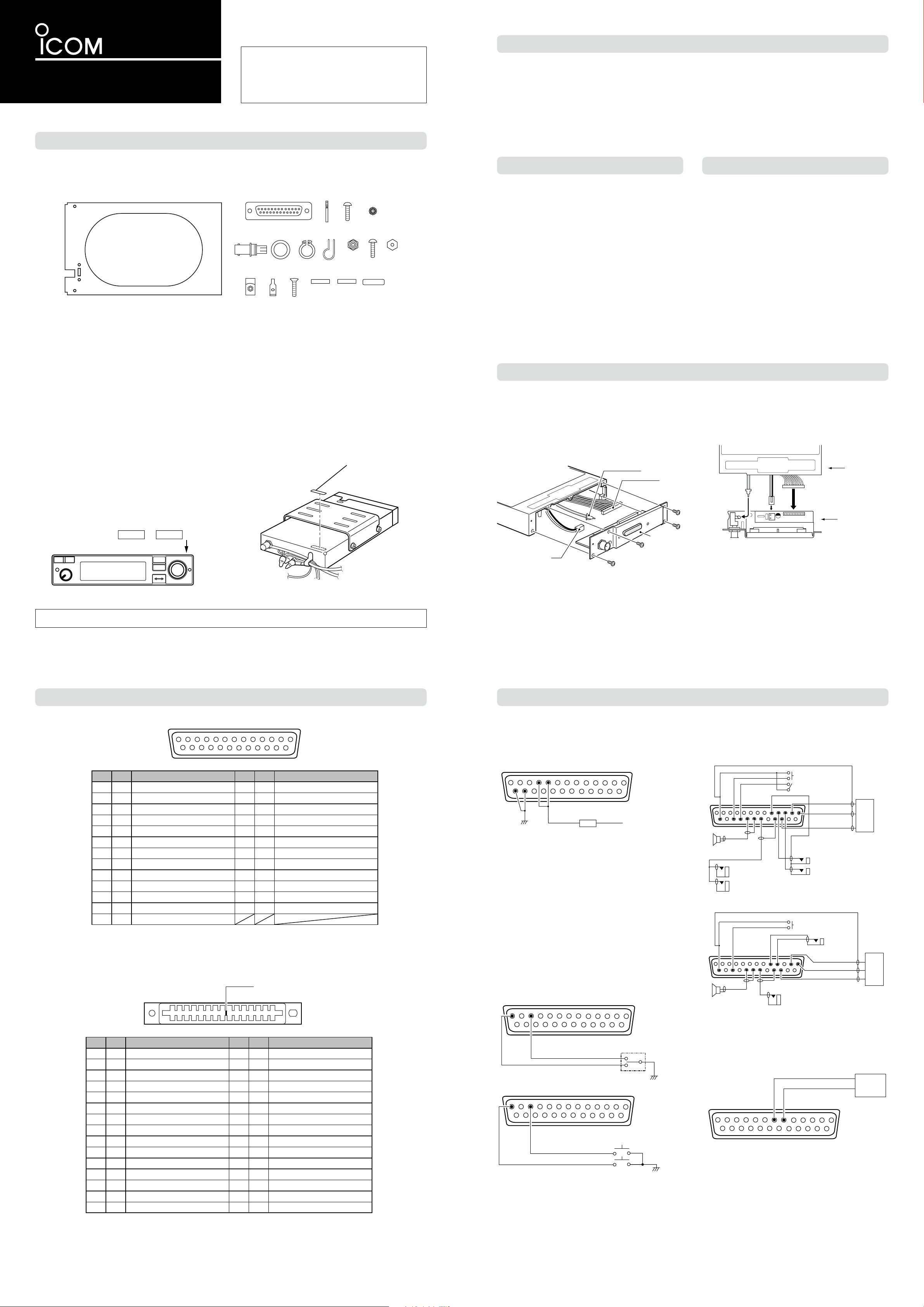
z SUPPLIED ACCESSORIES
Thank you for choosing the IC-A220/IC-A220E v h f
a i r b a n d t r a n s c e i v e r
with Icom’s state of the art
technology.
Carefully read this installation guide and the transceiver’s instruction manual before installing and operating your transceiver.
x IMPORTANT
READ THIS INSTALLATION GUIDE
install the transceiver. This installation guide contains important safety instructions.
NEVER install the transceiver where normal navigation of
the aircraft may be hindered.
NEVER install an antenna near any aircraft projection, en-
gine, or propeller.
Install a circuit breaker between the aircraft battery and the
transceiver.
CAREFULLY before
Check operation after installation.
Install the transceiver according to the procedures of this installation guide.
The antenna should be spaced at least 40 cm (1.3 feet) from
any position occupied by any person on board the aircraft or
the vehicle.
The following accessories are supplied with the transceiver.
Carefully check the quantity of each part.
q Mounting bracket ………………………………………… 1
w D-Sub 25 pin connector ……………………………… 1
e Connector pins (M39029/63-368) ……………………… 25
r Screws Bind UNC (No. 4 × 3/8)………………………… 2
t K-Lock Nut (No. 4) ……………………………………… 2
y BNC -LP ………………………………………………… 1
u Washer (Icom washer V) ……………………………… 1
i C-shaped ring …………………………………………… 1
o Antenna cable clip ……………………………………… 1
!0 Self crimping nut (No. 6) ……………………………… 1
!1 Screw (No. 6 × 1/2) ……………………………………… 1
!2 Nut (No. 6) ……………………………………………… 1
!3 Crimp nuts (No. 6) ……………………………………… 6
!4 Speed nut UNC (No. 6) ………………………………… 4
!5 Screws (No. 6 × 1/2) …………………………………… 6
!6 COMM1 sticker ………………………………………… 1
!7 COMM2 sticker ………………………………………… 1
!8 Voltage sticker (For only IC-A220E) …………………… 1
c INSTALLATION PROCEDURES
q Check the quantity of parts.
Refer to z SUPPLIED ACCESSORIES.
w Prepare miscellaneous items required for installation.
Refer to miscellaneous items in z SUPPLIED ACCES-
SORIES.
e Prepare the required wiring.
Refer to n CONNECTOR INFORMATION and m CON-
NECTING THE CABLES FOR D-SUB 25 PIN.
• If you want to use the MBA-3 connector, refer to b US-
ING THE MBA-3 and , CONNECTING THE CABLES FOR
CARD EDGE CONNECTOR.
r Assemble supplied mounting bracket and other parts.
Refer to . MOUNTING BRACKET ASSEMBLY.
t Cut the mounting hole.
Refer to ⁄0 MARKING A MOUNTING HOLE.
y Mount the transceiver into the mounting bracket.
Refer to ⁄1 MOUNTING TO THE BRACKET.
u Check the transceiver operation.
Refer to ⁄2 OPERATION CHECK.
b USING THE MBA-3
When installing the transceiver with card edge connector, use
the optional MBA-3 as described below.
v PRECAUTIONS
NEVER bend the cables sharply or place the cables too near
the aircraft control cables.
DO NOT place the transceiver where hot or cold air blows directly on it.
AVOID placing the transceiver in areas with temperatures below –20˚C or above +55˚C (–4˚F to +131˚F).
NEVER connect the transceiver to a power source using reverse polarity. Reverse polarity will damage the transceiver.
To prevent voltage drops, solder or crimp the cable lug when
connecting the DC power cable to the power supply.
Use a 50 Ω, vertically polarized, VHF air band antenna.
VSWR should be less than 2.5:1.
Mount the antenna on a flat metal surface or install a ground
plane of at least 120 cm
2
(18 in2).
The following items are required for installation but are NOT
supplied with the transceiver.
• VHF antenna for the air communication band
• Various cables
D
Voltage sticker
(For only IC-A220E)
When you install the transceiver in the optional MB-53,
attach the supplied voltage sticker on the MB-53.
• An antenna cable with a BNC connectors (50 Ω)
• Switches to be mounted on the aircraft yoke
• Headphones. (500 Ω)
• Low-impedance carbon or dynamic microphone
• Preamplier for a dynamic microphone
D
COMM1 and COMM2 stickers
When two transceivers are installed, attach the supplied COMM1
and COMM2 stickers to distinguish one from the another.
Icom, Icom Inc. and Icom logo are registered trademarks of Icom Incorporated (Japan) in Japan, the United States, the United Kingdom, Germany, France, Spain,
Russia, Australia, New Zealand, and/or other countries.
D Attachment
Unscrew the 10 bottom screws, then remove the bottom q
cover from the transceiver.
Unscrew the four rear plate screws. w
Disconnect the I/O cable connectors J3, J4, and coaxial e
J6 , and then remove the rear plate from the transceiver.
Connect the I/O cable connectors and coaxial onto the r
MBA-3 as illustrated below.
Attach the MBA-3 to the transceiver with the five rear plate t
screws.
Replace the removed bottom cover and 10 screws. y
n CONNECTOR INFORMATION
D D-sub 25-pin
Pin I/O Description Pin I/O Description
1 In Memory Channel Switch* 14 – Aircraft ground
2 In Transmit/receive Interlock 15 – Aircraft ground
3 In Frequency Exchange Switch* 16 In PTT*
4 In DC power + (13.8/27.5 V) 17 In Intercom switch*
5 In DC power + (13.8/27.5 V) 18 Out
6 – RS-232C Serial data (GND) 19 – External speaker
7 Out RS-232C Serial data (TXD) 20 Out
8 In RS-232C Serial data (RXD) 21 In
(
9 – Microphone
10 In Microphone 1 (600 Ω) 23 In Auxiliary audio 3
11 In Microphone 2 (600 Ω) 24 – (reserved)
12 In Auxiliary audio 1 25 – (reserved)
13 In Auxiliary audio 2
GND) 22 –
External speaker (4 Ω/5 W)
(
GND)
Headphones audio (500 Ω/60 mW)
External Dimmer control
(
Headphones audio
GND)
*Ground to activate.
m CONNECTING THE CABLES FOR D-SUB 25 PIN
D Power cable wiring
Use two pairs of #20 AWG wire for the power and power
grounding connections.
Rear view
• Circuit breaker
To prevent physical damage, a 10 A circuit breaker MUST be
installed in the DC power line in the aircraft. Install the circuit
breaker in the aircraft breaker panel or instrument panel to
ensure easy access during flight.
• Power Ground
Connect the transceiver power ground to the aircraft ground.
D Yoke-mounted memory and frequency exchange
switches
D Audio line connections
Use #20 ~ #24 AWG wires for connections.
Rear view
D Card edge connector (For optional MBA-3)
Pin I/O Description Pin I/O Description
A I
B – (reserved) 2 In RS-232C Serial data (RXD)
C In Auxiliary audio 2 3 In Auxiliary audio 3
D In Auxiliary audio 1 4 – Auxiliary audio 1/2/3 (GND)
E Out External speaker (4 Ω/5 W) 5 – External speaker (GND)
F – Aircraft ground 6 – Aircraft ground
H Out
J In Microphone 1 (600 Ω) 8 – Microphone (GND)
K In Microphone 2 (600 Ω) 9 In PTT*
L In Memory channel switch* 10 In Intercom switch*
M – (reserved) 11 – (reserved)
External Dimmer Control
Headphones audio (500 Ω/60 mW)
1 Out RS-232C Serial data (TXD)
7 – Headphones audio (GND)
N I Transmit/receive interlock 12 In Frequency exchange switch*
P – (reserved) 13 – (reserved)
R In DC power + (13.8/27.5 V) 14 In DC power + (13.8/27.5 V)
S – Aircraft ground 15 – Aircraft ground
*Ground to activate.
For the yoke-mounted memory and frequency exchange
switches, use a two-position spring loaded rocker switch or
two separate momentary push switches.
Rear view
D Transmit/receive interlock connections
When two transceivers are installed, connect pin 2 to the
other transceiver
transceiver
simultaneously transmitting.
However, when two transceivers are installed through a dual
audio panel, the connections are not necessary.
’s PTT line, and connect pin 16 to the other
’s interlock line to prevent both transceivers from
D GPS receiver connection
Connect the GPS receiver’s input terminal to the pin 7, and
output terminal to pin 8.
Rear view
Page 2
L-type BNC
connector
(User supplied, if required)
Coaxial
connector
y BNC-LP
yBNC-LP
!2 Nut
o Antenna cable clip
!0 Self-crimping nut
u Washer
i C-shaped ring
!4 Screws
!1 Screw
r Screws Bind UNC
q Mounting
bracket
w D-sub 25 pin connector
!3 Crimp nut
q Mounting
bracket
e Connector pins
t K-Lock Nut
160 mm (6.3″)
33 mm (1.3″)
260 mm (10.2
″)
160 mm (6.3″)
34 mm (1.3″)
RCL
MEM
OFF
VOL
PUSH
TEST
COMM
DUAL
EC
118.00
128.10
160 mm (6
5
⁄
16
″)
33 mm (1
5
⁄
16
″)
Main unit front view
Fig. 1
Fig. 6Fig. 5
Fig. 7
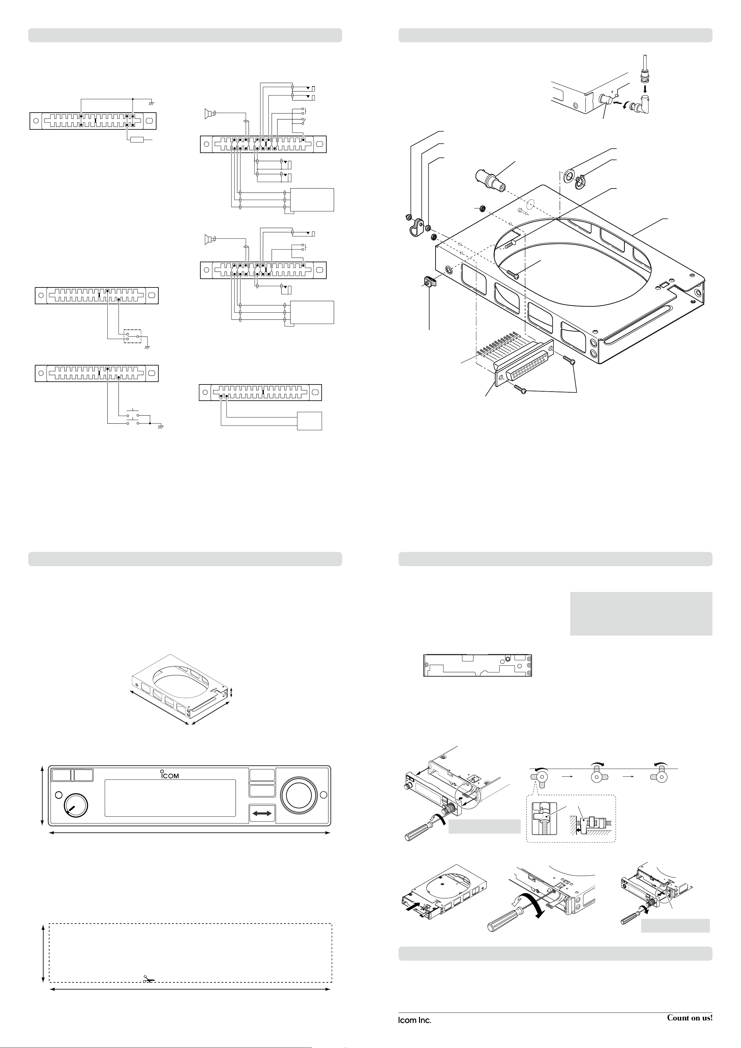
CAUTION: Treat the cable with
care when disconnecting it.
CAUTION: Treat the cable
with care when connecting it.
Clockwise: For attaching.
Counterclockwise: For removal.
Surface
Cable
Fig. 2 Fig. 4Fig. 3
Screw four revolutions Unscrew a quarter
revolution
• Metal catch position
Metal catch
A FRS
1 614 15
Circuit
breaker
(10 A)
+
13.8 V DC
or 27.5 V DC
Power ground
_
A ECD S
1 54
H
78 910 15
A ECD S
1 54
HJ
78 9 15
External speaker
Headphone jack 1
(to 500 Ω Headphones)
Auxiliary audio 1
Auxiliary audio 2
Auxiliary audio 3
Audio control panel
Headphone jack 2
Microphone
jack 1
Microphone
jack 2
PTT switch
Intercom switch
External speaker
Headphone jack
Auxiliary audio 1
Auxiliary audio 2
Auxiliary audio 3
Audio control panel
Microphone
jack
PTT switch
• Two headsets with intercom
• One headset
KJ
3
AS
1152
GPS
receiver
GPS receiver’s input
GPS receiver’s output
, CONNECTING THE CABLES FOR CARD EDGE CONNECTOR (MBA-3)
Memory switch
Frequency
exchange
switch
Memory switch
Frequency
exchange
switch
AS
1
L
12
15
OR
A
L
S
1
12
15
. MOUNTING BRACKET ASSEMBLY
D Power cable wiring
Use two pairs of #18 AWG wire for the power and power
connections.
Rear view
• Circuit breaker
To prevent physical damage, a 10 A circuit breaker MUST be
installed in the DC power line in the aircraft. Install the circuit
breaker in the aircraft breaker panel or instrument panel to
ensure easy access during flight.
• Power Ground
Connect the transceiver power ground to the aircraft ground.
D Yoke-mounted memory and frequency exchange
switches
D Audio line connection
Use #24 AWG wire for the connections.
For the yoke-mounted memory and frequency exchange
switches, use a two-position spring loaded rocker switch or
two separate momentary push switches.
Rear view
D GPS receiver connection
Connect the GPS receiver’s input terminal to the pin 1, and
output terminal to pin 2.
Rear view
D Transmit/receive interlock connections
When two transceivers are installed, connect pin N to the
other transceiver
transceiver
’s PTT line, and connect pin 9 to the other
’s interlock line to prevent both transceivers from
simultaneously transmitting.
However, when two transceivers are installed through a dual
audio panel, the connections are not necessary.
⁄0 MARKING A MOUNTING HOLE
D Notes for making the mounting hole
The transceiver can be mounted securely in the supplied
mounting bracket.
Remember to allow adequate space for installation of cables
and connectors.
When installing two or more transceivers in a stack, the mounting bracket should be 1.3 mm
D Mounting bracket dimensions
(0.05″) apart.
The mounting bracket has 0.6 mm
(0.024″) dimples in the
top, bottom, and both sides for proper spacing.
Mark and cut the mounting holes.
To support the mounting bracket, the rear mounting bosses
should be attached to the airframe.
⁄1 MOUNTING TO THE BRACKET
D Transceiver installation
Remove the front panel from the transceiver’s main unit. q
- Use a
- Carefully disconnect the cable from the front panel.
(Fig. 1)
Insert a w
and unscrew the inside lock screw until the metal catch
touches the chassis hole. (Fig. 2)
Main unit front view
3
⁄32″ allen wrench.
3
⁄32″ allen wrench into the hole of the main unit
Connect the cable. (Fig. 7) y
Attach the front panel and tighten the allen screws . u
(Fig. 7)
CAUTION: Make sure that the cable between the transceiver and front panel is securely connected. The transceiver may not function properly when loose or when a
wrong connection is made.
Improper cable connection can cause damage and result
in severe non-warranty repair.
D Transceiver removal
The transceiver can be easily removed from the mounting
bracket, if required.
D Front panel dimensions
Allow space for the front panel as shown above.
Remove the front panel from the transceiver's main unit. q
3
⁄32″ allen wrench.
3
⁄32″ allen wrench into the hole of the main unit and
Rotate the lock screw clockwise four revolutions (Fig. 3), e
and then rotate counterclockwise a quarter revolution.
(Fig. 4)
Insert the main unit (transceiver) into the mounting brack- r
et. (Fig. 5)
Screw the lock screw to fix the main unit (transceiver) to t
the bracket. (Fig. 6)
- Use a
- Carefully disconnect the cable from the front panel.
Insert a w
unscrew the inside lock screw.
Slowly pull the transceiver out from the mounting bracket. e
Connect the cable to the front panel. r
Attach the front panel and tighten the allen screws. t
D Template
Cut out dimensions for the mounting bracket as follows.
⁄2 OPERATION CHECK
Check the following points after transceiver installation.
- Polarity of the power supply.
- NO interference caused to other equipment.
- NO noise or interference from other equipment.
1-1-32 Kamiminami, Hirano-ku, Osaka 547-0003, Japan
Printed on recycled paper with soy ink.
- VSWR is less than 2.5:1.
- Communication capability on both the highest and lowest
communication frequencies, if possible.
A-7210D-2EX-a
Printed in Japan
© 2015 Icom Inc.
 Loading...