

Page 1

ADVANCED INSTRUCTIONS
INTRODUCTION
1 PANEL DESCRIPTION
2 INSTALLATION AND CONNECTIONS
3 BASIC OPERATION
4 RECEIVE AND TRANSMIT
HF/VHF/UHF ALL MODE TRANSCEIVER
i7100
5 FUNCTIONS FOR RECEIVE
6 FUNCTIONS FOR TRANSMIT
7 D-STAR INTRODUCTION
8 D-STAR OPERATION <BASIC>
9 D-STAR OPERATION <ADVANCED>
10 GPS/GPS-A OPERATION
11 MEMORY OPERATION
12 SCAN OPERATION
13 USING AN SD CARD
14 VOICE MEMORY FUNCTION
15 VOICE TX FUNCTION
16 ANTENNA TUNER OPERATION
17 SET MODE
18 DATA COMMUNICATION
19 MAINTENANCE
20 CONTROL COMMAND
21 SPECIFICATIONS AND OPTIONS
Page 2

3
BASIC OPERATION
3-13
Previous view
Setting frequency (Continued)
Band edge warning beep D
You can hear a beep tone when you tune into or out
of an amateur band’s frequency range. A regular beep
sounds when you tune into a range, and an lower tone
error beep sounds when you tune out of a range.
Push q
SET
(C) to enter the Set mode.
Touch the “Band Edge Beep” item of the “Function” w
Set mode.
Function >
Band Edge Beep
• If the specifi ed item is not displayed, touch [Y] or [Z](D)
one or more times to select the page.
Touch the desired option to e select the desired band
edge warning beep setting, or to turn OFF the func-
tion.
• OFF: Band edge beep is OFF.
• ON (Default): When you tune into or out of the default
amateur band’s frequency range, a beep
sounds. (default)
• ON (User): When you tune into or out of a user pro-
grammed amateur band’s frequency range,
a beep sounds.
• ON (User) & TX Limit:
When you tune into or out of a user pro-
grammed amateur band’s frequency range,
a beep sounds. Also transmission is inhib-
ited outside the programmed range.
• If desired, touch the item for 1 second to open the Default
set window, then select the “Default” to reset to the de-
fault setting.
Push r
SET
(C) to exit the Set mode.
If the “” item is set to “0, ” the Band edge
beep does not sound. The beep output level can be
set in the “Beep Leve l” item of the “Function” Set
mode. (p. 17-18)
About the user band edge frequencies
When “ON (User)” or “ON (User) & TX Limit” is selected
in the “Band Edge Beep” item, a total of 30 band edge
frequencies can be p rogrammed in the “User Band
Edge” item. See the next page for details.
If “OFF” or “ON (Default)” is selected, the “User Band
Edge” item does not appear in the “Function” Set
mode.
The L, R, C or D in the
instructions indicate the
part of the controller.
L: Left side
R: Right side
C: Center bottom
D:
Display (Touch screen)
L
eft
R
ight
C
enter
D
isplay
Touch
“Function”
Push
SET
Touch “Band
Edge Beep”
veBeep Le l
INTRODUCTION
If the “” item is set to “0, ” the Band
veBeep Le l
Previous view
SET
About these Advanced Instructions (PDF format)
These Advanced Instructions describe the details of the IC-7100 features. This PDF formatted manual provides you
with convenient functions, as follows.
NOTE: Below page is used only as an example to describe these advanced instructions.
Move to the previously read page.
Previous view
Click
each page, to move back to the previ-
ously read page.
Shows a term description
When the mouse cursor is moved over
a term which is highlighted in yellow, the
description of the term is displayed.
at the left top on an
The location of the keys used in the
described steps are illustrated.
Example: Push
(C).
Moves to the page, if clicked.
(p. 17-18)
Icom, Icom Inc. and the Icom logo are registered trademarks of Icom Incorporated (Japan) in Japan, the United States, the
United Kingdom, Germany, France, Spain, Russia and/or other countries.
Adobe and Adobe Reader are registered trademark of Adobe Systems Incorporated.
All other products or brands are registered trademarks or trademarks of their respective holders.
The screen
shots at the
right column,
correspond to
the operating
instructions
and procedures
shows both set-
ting and operat-
ing example.
The location of the keys used in the described
steps in the left column are illustrated.
i
Page 3

INTRODUCTION
Functions and features of Adobe® Reader
®
The following functions and features can be used with Adobe
•Keywordsearch
Click “Find (Ctrl+F)” or “Advanced
Search (Shift+Ctrl+F)” in the Edit
menu to open the search screen.
This is convenient when search-
ing for a particular word or phrase
in this manual.
* The menu screen may differ, depend-
ing on the Adobe
®
Reader® version.
Click to open the find or search
screen or advanced search screen.
Reader®.
®
•Findscreen
•Advancedsearchscreen
•Printingoutthedesiredpages.
Click “Print (P)” in File menu, and then select the pa-
per size and page numbers you want to print.
* The printing setup may differ, depending on the
printer. Refer to your printer’s instruction manual
for details.
* Select "A4" size to print out the page in the equal-
ized size.
•ReadOutLoudfeature.
The Read Out Loud feature reads aloud the text in
this Instruction Manual.
Refer to the Adobe
®
Reader® Help for the details.
( This feature may not be usable, depending on your
PC environment including the operating system.)
*The screen may differ, depending on the Adobe® Reader® version.
ii
Page 4

INTRODUCTION
About the touch screen
The following functions and features can be used with Adobe
Touch operation
®
Reader®.
A brief touch D
If the monitor is touched briefly, a beep sounds.
Touch for 1 second D
If the monitor is touched for more than 1 second, a
beep sounds.
•Theoperationisenabledasthebeepsounds.
What to touch
The following functions can be touched to operate.
•Seeeachfunction’sinstructionsforfurtherdetails.
Frequency
(MHz)
Frequency
Operating
mode
(kHz)
Filter No.
Frequency
(Hz)
VFO mode/
Memory mode
D Touch screen precautions
Briefly touching the controller’s touch operates the
function.
•ThetouchscreenmaynotproperlyworkwhenLCDprotec-
tion film or sheet is attached.
•Touchingthescreenwithngernails,sharptoppedobject
and so on, or touching the screen hard may damage the
screen.
•TabletPC’soperationssuchasickinput,pinchinand
pinch out cannot be performed with this touch screen.
D Touch screen maintenance
•Ifthetouchscreenbecomesdustyordirty,wipeitclean
with a soft, dry cloth.
•Whenyouwipethetouchscreen,becarefulnottopushit
too hard or scratch it with finger nails. Otherwise you may
damage the touch screen.
Touch key for each function.
(Example: M-1 menu is selected.)
Meter type
iii
Page 5

Section 1
PANELDESCRIPTION
Controller — Front panel ........................................................1-2
Controller — Function display ...............................................1-8
Controller — Multi-function keys ...........................................1-11
M-1 (M-1 menu) Display D ..........................................................1-11
M-2 (M-2 menu) Display D ..........................................................1-11
M-3 (M-3 menu) Display D ..........................................................1-11
D-1 (D-1 menu) Display D ...........................................................1-11
D-2 (D-2 menu) Display D ...........................................................1-11
Function keys on M-1 display D ..................................................1-12
Function keys on M-2 display D ..................................................1-12
Function keys on M-3 display D ..................................................1-13
Function keys on D-1 display D ..................................................1-14
Function keys on D-2 display D ..................................................1-14
Controller — Rear and bottom panels ...................................1-15
Main unit — Front panel ..........................................................1-16
Main unit — Rear panel ...........................................................1-17
ACC socket information D ...........................................................1-19
DATA2 socket information D ........................................................1-20
Microphone connector information D ..........................................1-20
Microphone ..............................................................................1-21
HM-198 (Supplied) D ..................................................................1-21
SM-50 D (Option) ........................................................................1-22
SM-30 D (Option) ........................................................................1-22
HM-151 D (Option)......................................................................1-23
1-1
1-1
Page 6

PANEL DESCRIPTION
Increases
Decreases
SET
Maximum
RF gain
S-meter
squelch
Noise squelch (FM/DV modes)
Squelch is
open.
RF gain
adjustable
range
Recommended level
Minimum RF gain
Adjustable
range
Maximum
RF gain
Squelch is
open.
S-meter
squelch
S-meter squelch
threshold
Noise squelch
threshold
(FM/DV modes)
Shallow Deep
Noise squelch (FM/DV modes)
PBT RIT
TX / RX
PWR
AF RF/SQL
CLR
M-CH BANK
RIT
TUNER/CALL
MENU
MIC/RF PWRNBSPEED/PITCH
SET
QUICK
NOTCH
DR
AUTO TUNE
RX�CS
XFC
SPEECH
MPAD
NR
P.AMP
ATT
i7100
1
Controller — Front panel
q
w
qPOWERSWITCH•AFVOLUME[PWR]•[AF]
(p. 3-2)
Push to turn ON the transceiver power. ➥
•First,conrmtheDCpowersourceisturnedON.
Hold down for 1 second to turn OFF the power. ➥
Rotatetoadjusttheaudiooutputlevel. ➥
wRFGAINCONTROL/SQUELCHCONTROL
[RF/SQL] (p. 3-19)
RotatetoadjusttheRFgainandsquelchthreshold
levels.
The squelch removes noise output to the speaker
when no signal is received. (closed condition)
•WhenusedasanRFgain/squelchcontrol
•WhenusedasanRFgaincontrol
(Squelch is fixed open; SSB, CW and RTTY only)
While rotating the RF gain control, a faint noise may
be heard. This comes from the DSP unit and does
not indicate an equipment malfunction.
•Whenusedasasquelchcontrol
(RF gain is fixed at maximum.)
•ThesquelchisparticularlyeffectiveforAMandFM,but
•The12to1o’clockpositionisrecommendedforthemost
•[RF/SQL]operatesasonlyanRFgaincontrolinSSB,
also works in other modes.
effective use of the [RF/SQL] control.
CW and RTTY (Squelch is fixed open), or a squelch con-
trol in AM, FM, WFM and DV (RF gain is fixed at maxi-
mum sensitivity), when “Auto” is selected as the “RF/SQL
Control” item in the “Function” Set mode. (p. 17-18)
> Function > RF/SQL Control
1-2
Page 7

PANEL DESCRIPTION
RIT
PBT RIT
TX / RX
PWR
AF RF/SQL
CLR
M-CH BANK
RIT
TUNER/CALL
MENU
MIC/RF PWRNBSPEED/PITCH
SET
QUICK
NOTCH
DR
AUTO TUNE
RX�CS
XFC
SPEECH
MPAD
NR
P.AMP
ATT
i7100
1
Controller — Front panel (Continued)
e
r
t
y
u
i
eTX/RXLED
Lights green when the squelch opens, or a signal ➥
is received.
Lights red when transmitting. ➥
rMEMORYBANKCONTROL[BANK]
❍ When both the PBT and RIT LEDs are OFF
Rotate to select a Memory bank.
❍ When the PBT LED (y) lights green
(Mode:SSB/CW/RTTY/AM)
Rotatetoadjustthereceiver’sIFlterpassband
width using the DSP circuit.
❍ When the RIT LED (u) lights orange
Disable this control.
tM-CHCONTROL•CLEARSWITCH[M-CH]•[CLR]
Push to select the action of the [M-CH/BANK] con-
trols as the Memory/Bank selection, PBT control or
RIT control.
❍ When the both RIT and PBT LEDs are OFF
Rotate to select a Memory channel.
❍ When the RIT LED lights orange
➥RotatetoadjusttheRITfrequencyshift.
•Thefrequencyshiftrangeis±9.99kHzin10Hz
steps. The control tunes in 1 Hz steps when the op-
erating frequency readout is set to the 1 Hz step.
➥ Hold down for 1 second to clear the RIT shift
frequency.
✔ What is the RIT function?
The RIT (Receiver Incremental Tuning) shifts the re-
ceive frequency without shifting the transmit frequency.
This is useful for fine tuning stations calling you off-fre-
quency, or when you prefer to listen to slightly different-
sounding voice characteristics.
❍ When the PBT LED lights green
(Mode:SSB/CW/RTTY/AM)
➥Rotatetoadjustthereceiver’sIFlterpass-
band width using the DSP circuit.
➥
Hold down for 1 second to reset the PBT set-
tings.
•ThePBTisadjustablein50HzstepsintheSSB/
CW/RTTY modes, and 200 Hz in the AM mode. At
that time, the shift value changes in 25 Hz steps in
the SSB/CW/RTTY modes, and 100 Hz in the AM
mode.
•ThePBTcontrolsfunctionasanIFshiftcontrol.
✔ What is the PBT control?
The PBT function electronically modifies the IF pass-
bandwidthtorejectinterference.Thistransceiveruses
the DSP circuit for the PBT function.
yPBTLED
Lights green when the [M-CH/BANK] controls act
as the PBT control.
•Pushthe[M-CH] switch to select PBT control.
uRITLED
Lights orange when the RIT function is turned ➥
ON.
Lights orange when the [M-CH/BANK] ➥ controls
act as the RIT control.
•Pushthe[M-CH] switch to select RIT control.
•The RIT control is the inner control. The outer control
is disabled.
iRITKEY
(p. 5-4)
Push to turn the RIT function ON or OFF. ➥
•Usethe[M-CH] control to vary the RIT frequency.
➥ Hold down for 1 second to add the shift frequency
of the RIT function to, or subtract it from, the dis-
played frequency.
1-3
Page 8

PANEL DESCRIPTION
TUNER/CALL
MENU
MIC/RF PWR
NB
SPEED/PITCH
NR
PBT RIT
TX / RX
PWR
AF RF/SQL
CLR
M-CH BANK
RIT
TUNER/CALL
MENU
MIC/RF PWRNBSPEED/PITCH
SET
QUICK
NOTCH
DR
AUTO TUNE
RX�CS
XFC
SPEECH
MPAD
NR
P.AMP
ATT
i7100
1
Controller — Front panel (Continued)
o !0 !2 !4!1 !3
oANTENNATUNER/CALLKEY
❍ ANTENNA TUNER KEY Operation (p. 16-4)
(Frequencyband:HF/50MHz)
➥ Push to turn an optional automatic antenna
tuner ON or OFF (bypass).
➥ Hold down for 1 second to manually tune the
antenna tuner.
•Ifthetunercannottunetheantennawithin20sec-
onds, the tuning circuit is automatically bypassed.
❍ CALL KEY Operation (p. 11-4)
(Frequencyband:144/430MHz)
Push to select the Call channel.
In the 70 MHz band, push to sound an error beep.
!0MENUKEY
(p. 1-11)
Push to change the set of functions assigned to the
touch keys.
•TogglesthefunctiondisplaymenubetweenM-1,M-2and
M-3 menus or D-1 and D-2 menus.
!1MICGAIN/RFPOWERADJUSTMENTKEY
(p. 3-24)
PushtoopentheMICgain/RFpoweradjustment
display.
•Rotate[M-CH]toadjusttheMICgain.
•Rotate[BANK]
FrequencybandRF output power range
HF/50 MHz 2 to 100 W (AM: 1 to 30 W)
toadjusttheRFpower.
70 MHz* 2 to 50 W (AM: 1 to 15 W)
144 MHz 2 to 50 W
•Pushagaintoclosethewindow.
430 MHz 2 to 35 W
!2NOISEBLANKERKEY
(p. 5-8)
(Mode:SSB/CW/RTTY/AM)
Push to turn the noise blanker ON or OFF. ➥
The noise blanker reduces pulse-type noise such
as that generated by vehicle ignition systems. The
noise blanker is not effective for non-pulse-type
noise.
•“NB”appearswhenthenoiseblankerisON.
Hold down for 1 second to display the “NB” screen. ➥
Push to return to the previous screen.
!3KEYSPEED/CWPITCHADJUSTMENTKEY
(pp. 4-4, 6-4)
PushtoopentheKeyspeed/CWpitchadjustment
display.
•Rotate[M-CH]toadjustthekeyingspeedoftheinter-
nal electronic CW keyer to between 6 wpm (minimum)
and 48 wpm (maximum).
•Rotate[BANK]
to shift the received CW audio pitch
and the CW sidetone pitch without changing the operat-
ing frequency.
•TheCWpitchcanbeadjustedfrom300to900Hzinap-
proximately 5 Hz steps.
•Pushagaintoclosethewindow.
!4NOISEREDUCTIONKEY
(p. 5-9)
Push to turn DSP noise reduction ON or OFF. ➥
•“NR”appearswhennoisereductionisON.
Hold down for 1 second to display the “NR” screen. ➥
Push to return to the previous screen.
•RotatetheDialtoadjusttheDSPnoisereduction
level. Set for maximum readability.
* 70 MHz band transmission is available, depending on the
transceiver version.
1-4
Page 9

PANEL DESCRIPTION
P.AMP
ATT
NOTCH
SET
SET
PBT RIT
TX / RX
PWR
AF RF/SQL
CLR
M-CH BANK
RIT
TUNER/CALL
MENU
MIC/RF PWRNBSPEED/PITCH
SET
QUICK
NOTCH
DR
AUTO TUNE
RX�CS
XFC
SPEECH
MPAD
NR
P.AMP
ATT
i7100
1
Controller — Front panel (Continued)
!6!5
!5PREAMP•ATTENUATORKEY
❍ PREAMP KEY Operation (p. 5-2)
(Frequencyband:HF,50/70MHz)
Push to select one of two receive RF preampli-
fiers, or to bypass them.
•“P.AMP1”isawidedynamicrangepreamplier.Itis
most effective for the 1.8 to 21 MHz bands.
•“P.AMP2”isahigh-gainpreamplier.Itismosteffec-
tive for the 24 to 70 MHz bands.
•Noindicatorappearswhenthepreampliersarenot
selected.
✔ What is the preamplifier?
The preamplifier amplifies signals in the front end
to improve the S/N ratio and sensitivity. Select “P.
AMP1” or “P. AMP2” when receiving weak sig-
nals.
(Frequencyband:144/430MHz)
Push to turn the preamplifier ON or OFF.
•“P.AMP”appearswhenthepreamplierisON.
❍ ATTENUATOR KEY Operation (p. 5-2)
➥ Hold down for 1 second to turn ON the attenu-
ator.
•“ATT”appearswhentheattenuatorisON.
➥ Push to turn OFF the attenuator.
•“ATT”disappears.
✔ What is the attenuator?
The attenuator prevents a desired signal from be-
ing distorted when very strong signals are near it,
or when very strong electromagnetic fields, such
as from a broadcasting station, are near your lo-
cation.
!6NOTCHKEY
(p. 5-10)
(Mode=Autonotch:SSB/AM/FM
Manualnotch:SSB/CW/RTTY/AM)
➥In the SSB and AM modes, push to toggle the
notch function between auto, manual and OFF.
•EithertheAutoorManualnotchfunctioncanbeturned
OFF in
the “[NOTCH] Switch (SSB)/(AM)” items
“Function” Set mode. (p. 17-21)
> Function > [NOTCH] Switch (SSB)
> Function > [NOTCH] Switch (AM)
➥In the FM mode, push to turn the Auto Notch func-
tion ON or OFF.
➥ In
the CW or RTTY mode, push to turn the Manual
Notch function ON or OFF.
•“MN”appearswhentheManualNotchfunctionis
ON.
•“AN”appearswhentheAutoNotchfunctionisON.
•NoindicatorappearswhenthenotchlterisOFF.
➥ Hold down for 1 second to display the “NOTCH”
screen.
Push to return to the previous screen.
•RotatetheDialtoadjustthenotchfrequencytoreject
an interfering signal when the manual function is ON.
•Notchltercenterfrequency:
SSB/RTTY: –1040 Hz to +4040 Hz
CW: CW pitch frequency –2540 Hz to
CW pitch frequency +2540 Hz
AM: –5060 Hz to +5100 Hz
✔ What is the notch filter?
The notch filter is a narrow filter that eliminates un-
wanted CW or AM carrier tones, while preserving
the desired voice signal. The DSP circuit automati-
callyadjuststhenotchfrequencytoeffectivelyelimi-
nate unwanted tones.
of the
1-5
Page 10

PANEL DESCRIPTION
DR
SET
QUICK
AUTO TUNE
RX�CS
XFC
MPAD
XFC
PBT RIT
TX / RX
PWR
AF RF/SQL
CLR
M-CH BANK
RIT
TUNER/CALL
MENU
MIC/RF PWRNBSPEED/PITCH
SET
QUICK
NOTCH
DR
AUTO TUNE
RX�CS
XFC
SPEECH
MPAD
NR
P.AMP
ATT
i7100
1
Controller — Front panel (Continued)
!8 @0!7 @1!9
!7DRMODEKEY
➥ Push to select the DR mode.
(section 7,8,9)
•WhentheDRmodeisselected,thetransceiverauto-
matically selects the DV mode.
➥ In the DR mode, push to cancel it.
•Thetransceiverreturnstothepreviousscreenbefore
entering the DR mode.
!8SETMODEKEY
➥ Push to enter or exit the SET mode.
(section 17)
•“VoiceMemo,”“CallSign,”“RXHistory,”“DVMemory,”
“My Station,” “DV Set,” “GPS,” “SPEECH,” “QSO/RX
Log,” “Function,” “Tone Control,” “Connectors,” “Dis-
play,” “Time Set,” “SD Card” and “Others” set group
are selectable.
!9QUICKMENUKEY
➥ Push to open or close the Quick Menu window.
•TheQuickMenuisusedtoquicklyselectvarious
functions.
➥ In the setting screen, push to open the Default
set window.
•Touch“Default”toresettothedefaultsetting.
@0AUTOTUNE•RXCSKEY
❍ AUTO TUNE KEY Operation (p. 4-5)
(Mode:CW)
➥ Push to automaticallyadjustforazerobeat
with the received signal.
Zero beat means that two signals are exactly the
same frequency.
•“AUTOTUNE”blinkswhentheautotunefunction
•WhentheRITfunctionisON,theautotunefunc-
is activated.
tion changes the RIT frequency, not the displayed
frequency.
❍ RX CALL SIGN CAPTURE KEY Operation
(p. 8-7)
(Mode:DV,whentheDRmodeisselected)
➥ Push to open the “RX>CS” screen.
Push again to return to the previous screen.
➥ Hold down for 1 second to set the received call
signs (station and repeaters) as the operating
call sign.
@1
TRANSMITFREQUENCYCHECKKEY
➥ During split frequency or repeater operation, hold
down to listen to the transmit frequency. (p. 4-28)
•Whileholdingdownthisswitch,thetransmitfrequen-
cy can be changed with the Dial or
•WhentheSplitLockfunctionisturnedONintheSplit
operation, hold down
to cancel the Dial lock
function. (p. 6-10)
➥ When operating simplex, hold down to monitor
the frequency.
•Whileholdingdownthiskey,thesquelchisopenand
theinterferencerejectfunctionsaretemporarilyturned
OFF.
➥ When operating simplex and the RIT function is
turned ON, hold down to listen to the transmit fre-
quency. The frequency is the same as when the
RIT is OFF.
➥ In the DV mode, hold down this key to select the
RX monitoring mode. (p. 17-13)
.
1-6
Page 11

PANEL DESCRIPTION
SPEECH
SET
SET
SET
MPAD
SET
PBT RIT
TX / RX
PWR
AF RF/SQL
CLR
M-CH BANK
RIT
TUNER/CALL
MENU
MIC/RF PWRNBSPEED/PITCH
SET
QUICK
NOTCH
DR
AUTO TUNE
RX�CS
XFC
SPEECH
MPAD
NR
P.AMP
ATT
i7100
1
Controller — Front panel (Continued)
@5
@4
@2 @3
@2SPEECH•LOCKKEY
❍ SPEECH KEY Operation (p. 3-20)
Push to audibly announce the S-meter level, the
displayed frequency and the operating mode.
•TheS-LevelannouncementcanbeturnedOFFinthe
“S-Level SPEECH” item of the “SPEECH” Set mode.
(p. 17-15)
> SPEECH > S-Level SPEECH
•WhenRITisON,theRIToffsetisnotincludedinthe
frequency announcement.
❍ LOCK KEY Operation (p. 5-12)
Hold down for 1 second to turn the Lock function
ON or OFF.
•ThefunctionelectronicallylockstheDial.
“
•
” appears when the function is ON.
•YoucanselecttheDiallockandPanellockinthe
“Lock Function” item of the “Function” Set mode. (p.
17-20)
> Function > Lock Function
NOTE: The [SPEECH/LOCK] key operation to ac-
tivate the voice synthesizer or the Lock functions
can be replaced in the “[SPEECH/LOCK] Switch”
item of the “Function” Set mode. (p. 17-20)
> Function > Lock Function
@3MEMOPADKEY
(p. 11-13)
Push to sequentially call up the contents from the ➥
memo pad.
The 5 (or 10) most recently programmed frequen-
cies and operating modes can be recalled, start-
ing from the most recent.
•Thememopadcapacitycanbeincreasedfrom5to
10 in
the “Memopad Numbers” item
of the “Function”
Set mode (p. 17-20)
> Function > Memopad Numbers
Hold down for 1 second to write the displayed ➥
data into a memo pad.
•The5mostrecententriesremaininthememopad.
@4MAINDIAL
Rotate to change the displayed frequency, select the
Set mode settings, and so on.
@5MAINDIALTENSIONLATCH
Select the Dial drag.
•Threepositionsareselectable.Thetopsettingturnson
clicks as the dial is turned.
1-7
Page 12

PANEL DESCRIPTION
SET
1
Controller — Function display
q w e tr iy u
q TX ICON
Indicates either the displayed frequency can be
transmitted, or not.
➥“
” appears while the operating frequency is in
an amateur band.
➥“ ” appears while the operating frequency is
not in an amateur band. However, when the “Band
Edge Beep” item is set to “OFF” in the “Function”
Set mode (p. 17-18), “ ” does not appear.
> Function > Band Edge Beep
“LMT” appears while the output power is de- ➥
creased because the Power FET’s temperature
is high.
“HOT” appears while transmission is inhibited be- ➥
cause the Power FET’s temperature is too high.
w MODE ICONS (p. 3-17)
Displays the selected operating mode. ➥
•“-D”appearswhenSSBdata,AMdataorFMdata
mode is selected.
Touch to enter the Mode selection screen. ➥
•OntheModeselectionscreen,touchtheblocktose-
lect the operating mode.
e PASSBAND WIDTH ICON (pp. 5-5, 5-6)
Graphically displays the passband width for twin
PBT operation and the center frequency for IF shift
operation.
rTONESQUELCH/DIGITALSQUELCHICONS
(Mode:FM)
➥“TONE” appears when the repeater tone function
is ON. (p. 4-25)
➥“TSQL” appears when the tone squelch function
is ON. (p. 4-22)
➥“DTCS” appears when the DTCS function is ON.
(p. 4-23)
(Mode:DV)
➥“DSQL” appears when the digital call sign squelch
function is ON. (p. 9-22)
➥“CSQL” appears when digital code squelch func-
tion is ON. (p. 9-22)
tIFFILTERICON (p. 5-6)
Shows the selected IF filter. ➥
Touch to select one of three IF filter settings. ➥
•Theselectedlterpassbandwidthandshiftingvalue
are displayed for 2 seconds in the window.
Touch for 1 second to display the “FILTER” screen ➥
toadjustthelterpassbandwidth.
➥
When the “FILTER” screen is displayed, touch for 1
second to return to the previous screen.
yQUICKTUNINGICON(p. 3-8)
Appears when the Quick tuning mode is selected.
•When“Z” is displayed, the frequency changes in preset
kHz or 1 MHz quick tuning steps.
•When“Z” is not displayed, the frequency changes in 10
Hz or 1 Hz steps.
u GPS ICON (p. 10-2)
➥ Appears when valid position data is received from
a GPS receiver that is connected to the [DATA1]
jack.
➥Blinks when invalid data is received from the GPS
receiver.
i SD CARD ICON
➥“ ” appears when an SD card is inserted.
➥“ ” and “ ” alternately blinks while accessing the
SD card.
1-8
Page 13

PANEL DESCRIPTION
MENU
1
Controller — Function display (Continued)
!8
!7
o
!0
!1
!2
!3
!4
!5
!6
oCLOCKREADOUT
Shows the current time.
•UTCtimeorlocaltimecanbeselected.
!0SPLITICON (p. 6-8)
“ ” appears when the Split function is turned
ON.
!1LOCKICON (p. 5-12)
“ ” appears when the Lock function is activated.
1
⁄4 TUNINGDIALSPEEDICON(p. 3-10)
(Mode:SSB-D/CW/RTTY)
“ ” appears when the tuning dial speed is set so
that one rotation is equal to 1⁄4 of the normal rota-
tion.
•Thisfunctionisselectableonlywhenthequicktuning
function is turned OFF.
!2FREQUENCYREADOUTS
Displays the operating frequency. ➥
Touch the MHz digits to enter the Band selection ➥
screen.
Touch the MHz digits for 1 second to turn the 1 ➥
MHz quick tuning mode ON or OFF.
Touch the kHz digits to turn the preset kHz quick ➥
tuning mode ON or OFF.
Touch the kHz digits for 1 second to enter the Tun- ➥
ing step selection screen.
Touch the Hz digits to for 1 second to toggle be- ➥
tween 10 Hz and 1 Hz steps.
!3VFO/MEMORYICONS(p. 3-4)
“VFOA” or “VFOB” appears whether VFO A or ➥
VFO B is selected.
“MEMO” appears when the memory mode is se- ➥
lected.
!4MEMORYCHANNELREADOUT (p. 11-3)
Shows the selected memory channel, scan edge ➥
channel or Call channel.
•Memorybankindicator(AtoE)appearstotheleftof
memory channel.
Touch to toggle between the VFO and Memory ➥
modes.
!5 SELECTMEMORYCHANNELICON
“ ” appears when the selected memory channel is
set as a select memory channel.
(p. 12-12)
!6 INFORMATION READOUT
Displays the transmit frequency of the Split opera-
tion, descriptions of the memory channel or Re-
ceived Call sign in the DV mode, and so on.
!7FUNCTIONDISPLAY(p. 1-11)
Shows the function of the Touch keys.
•Push
the touch keys.
•TogglesthefunctiondisplaymenubetweenM-1,M-2,
and M-3 menus or D-1 and D-2 menus.
to change the set of functions assigned to
!8MULTI-FUNCTIONMETERINDICATION
➥Displays the signal strength while receiving.
➥Displays the relative output power, SWR, ALC or
compression levels while transmitting.
➥When the Meter Peak Hold function is ON, the
peak level of a received signal strength or the
output power is displayed for approximately 0.5
seconds.
➥Touch to select the RF power, SWR, ALC or Com-
pression meter.
➥Touch for 1 second to display the Multi-function
meter.
1-9
Page 14
PANEL DESCRIPTION
1
Controller — Function display (Continued)
!9
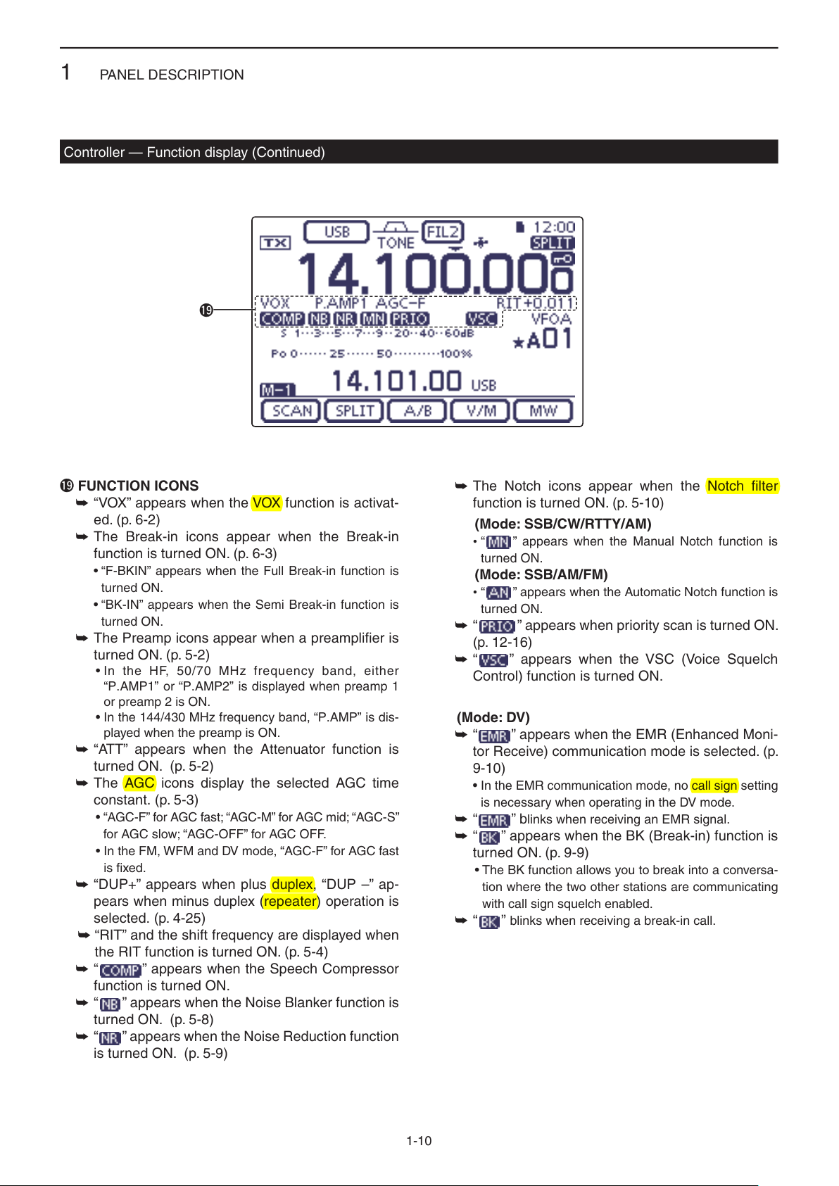
!9 FUNCTION ICONS
“VOX” appears when the VOX function is activat- ➥
ed. (p. 6-2)
The Break-in icons appear when the Break-in ➥
function is turned ON. (p. 6-3)
•“F-BKIN”appearswhentheFullBreak-infunctionis
turned ON.
•“BK-IN”appearswhentheSemiBreak-infunctionis
turned ON.
The Preamp icons appear when a preamplifier is ➥
turned ON. (p. 5-2)
•IntheHF,50/70MHzfrequencyband,either
“P.AMP1” or “P.AMP2” is displayed when preamp 1
or preamp 2 is ON.
•Inthe144/430MHzfrequencyband,“P.AMP”isdis-
played when the preamp is ON.
“ATT” appears when the Attenuator function is ➥
turned ON. (p. 5-2)
The AGC icons display the selected AGC time ➥
constant. (p. 5-3)
•“AGC-F”forAGCfast;“AGC-M”forAGCmid;“AGC-S”
for AGC slow; “AGC-OFF” for AGC OFF.
•IntheFM,WFMandDVmode,“AGC-F”forAGCfast
is fixed.
“DUP+” appears when plus duplex, “DUP –” ap- ➥
pears when minus duplex (repeater) operation is
selected. (p. 4-25)
➥“RIT” and the shift frequency are displayed when
the RIT function is turned ON. (p. 5-4)
“ ➥” appears when the Speech Compressor
function is turned ON.
“ ➥” appears when the Noise Blanker function is
turned ON. (p. 5-8)
“ ➥” appears when the Noise Reduction function
is turned ON. (p. 5-9)
The Notch icons appear when the Notch filter ➥
function is turned ON. (p. 5-10)
(Mode:SSB/CW/RTTY/AM)
•“ ” appears when the Manual Notch function is
turned ON.
(Mode:SSB/AM/FM)
•“ ” appears when the Automatic Notch function is
turned ON.
“ ➥” appears when priority scan is turned ON.
(p. 12-16)
“ ➥” appears when the VSC (Voice Squelch
Control) function is turned ON.
(Mode:DV)
” appears when the EMR (Enhanced Moni-
“ ➥
tor Receive) communication mode is selected. (p.
9-10)
•IntheEMRcommunicationmode,nocallsignsetting
is necessary when operating in the DV mode.
“ ➥” blinks when receiving an EMR signal.
➥“ ” appears when the BK (Break-in) function is
turned ON. (p. 9-9)
• The BK function allows you to break into a conversa-
tion where the two other stations are communicating
with call sign squelch enabled.
“ ➥”blinks when receiving a break-in call.
1-10
Page 15

PANEL DESCRIPTION
MENU
1
Controller — Multi-function keys
Push ➥
to touch keys.
•TogglesthefunctiondisplaymenubetweenM-1,M-2and
M-3 menus or D-1 and D-2 menus.
•Functionsvary,dependingontheoperatingmode.
•IntheDRmode,theD-1andD-2menuscanbeselect-
ed.
Touch or touch for 1 second to select the displayed ➥
functions.
to change the set of functions assigned
D M-1(M-1menu)Display
D M-2(M-2menu)Display
(Mode: SSB)
D M-3(M-3menu)Display
(Mode: SSB/AM/AM-D)
(Mode: SSB-D/RTTY)
(Mode: CW)
(Mode: SSB-D)
(Mode: CW)
(Mode: RTTY)
(Mode: AM/AM-D)
(Mode: FM/FM-D/WFM)
(Mode: DV)
(Mode: FM/FM-D/WFM/DV)
D D-1(D-1menu)Display
(Mode: DV, when the DR mode is selected)
D D-2(D-2menu)Display
(Mode: DV, when the DR mode is selected)
1-11
Page 16

PANEL DESCRIPTION
MENU
SET
SET
MENU
MENU
MENU
SET
MENU
SET
MENU
1
Controller — Multi-function keys (Continued)
D Function keys on M-1 display
SCANKEY[SCAN](p. 12-4)
Touch to display the “SCAN” screen.
•Push
SPLITKEY[SPLIT] (p. 6-8)
➥ Touch to turn the split function ON or OFF.
•“” appears when the split function is
ON.
➥ Touch for 1 second to activate the quick
split function.
•Thetransmitfrequencyshiftsfromthereceive
frequency according to the “SPLIT Offset” op-
tion in the “Function” Set mode. (p. 17-19)
•ThequicksplitfunctioncanbeturnedOFFin
the “Quick SPLIT” item
mode. (p. 17-19)
VFOSELECTKEY[A/B] (p. 3-5)
➥Touch to select either VFO A or VFO B.
➥Touch
played VFO settings to that of the displayed
VFO.
VFO/MEMORYKEY[V/M]
➥ Touch to switch between the VFO and
memory modes. (p. 3-4)
•TouchingMemorychannelalsoselectsthe
VFO or memory modes.
➥ Touch for 1 second to copy the memory
contents to the displayed VFO. (p. 11-9)
MEMORYWRITEKEY[MW] (p. 11-5)
Touch for 1 second to store VFO data into the
selected memory channel.
•ThiscanbedoneinboththeVFOandmemory
modes.
to return to the previous screen.
> Function > SPLIT/DUP > SPLIT Offset
of the “Function” Set
> Function > SPLIT/DUP > Quick SPLIT
for 1 second to equalize the undis-
D Function keys on M-2 display
DUPLEXKEY[DUP](p. 4-27)
➥ Touch to select the duplex direction, or to
turn OFF the function.
•“DUP–”or“DUP+”isdisplayedduringduplex
operation.
➥ In the FM mode, touch for 1 second to
turn the one-touch repeater function ON
or OFF.
AGCKEY[AGC] (p. 5-3)
(Mode:SSB/SSB-D/CW/RTTY/AM/AM-D)
➥ Touch to select the time constant of the
AGC circuit.
➥ Touch for 1 second to display the “AGC”
screen.
•Push
TONESQUELCHKEY[TONE](p. 4-24)
(Mode:FM)
➥ Touch to select a tone function between
subaudible (repeater) tone, tone squelch
and DTCS.
➥ Touch for 1 second to display the “TONE”
screen of the selected tone function.
•Push
DIGITALSQUELCHKEY[DSQL](p. 9-22)
(Mode:DV)
➥ Touch to select a digital squelch function
between digital call sign squelch and digi-
tal code squelch.
➥ Touch for 1 second to display the “DSQL”
screen (digital squelch).
•Push
VOICERECORDERKEY[VOICE](p. 15-2)
(Mode:SSB/AM/FM/DV)
This function requires to insert an SD card.
Touch to display the “VOICE TX” screen or
the “VOICE” (Root) screen, depending on the
“VOICE 1st Menu” option in the “Function” Set
mode
(p. 17-21)
> Function > VOICE 1st Menu
•Push
to return to the previous screen.
to return to the previous screen.
to return to the previous screen.
.
to return to the previous screen.
MEMORYKEYERKEY[KEYER](p. 4-6)
(Mode:CW)
Touch to display the “KEYER SEND” screen
or the “KEYER” (Root) screen, depending on
the “KEYER 1st Menu” option in the “Function”
Set mode
•Push
1-12
(p. 17-21)
> Function > KEYER 1st Menu
to return to the previous screen.
.
Page 17

PANEL DESCRIPTION
MENU
MENU
MENU
MENU
MENU
MENU
MENU
MENU
MENU
1
Controller — Multi-function keys (Continued)
Function keys on M-2 display (Continued) D
RTTYDECODERKEY[DEC](p. 4-12)
Touch to display the RTTY Decoder screen.
•Push
to return to the previous screen.
SPEECHCOMPRESSORKEY[COMP](p. 6-5)
(Mode:SSB)
➥ Touch to turn the speech compressor func-
tion ON or OFF.
•“” is displayed when the speech com-
pressor is ON.
➥ Touch for 1 second to display the “COMP”
screen.
•Push
to return to the previous screen.
RTTYSETKEY[RTTY](p. 6-5)
Touch to display the “RTTY SET” screen.
•Push
to return to the previous screen.
CALLSIGNKEY[CS](p. 4-13)
(Mode:DV)
Touch to display the “CALL SIGN” screen.
•ThecurrentcallsignforDVoperationappears.
•Push
to return to the previous screen.
TRANSMISSIONBANDWIDTHKEY[TBW](p. 6-6)
(Mode:SSB)
➥ Touch to display the selected
transmission
bandwidth.
➥ Touch for 1 second
to select the transmis-
sion bandwidth.
•Bandwidthisselectablefromwide(WIDE),
mid (MID) and narrow (NAR).
D FunctionkeysonM-3display
MEMORYNAMEKEY[MEMO](p. 11-10)
Touch to display the “MEMO” (Memory menu)
screen.
•Push
BANDSCOPEFUNCTIONKEY[SCOPE](p. 5-14)
Touch to display the “SCOPE” (Band scope)
screen.
SWRGRAPHFUNCTIONKEY[SWR](p. 6-13)
Touch to display the “SWR” screen.
•Push
DTMFMODEKEY[DTMF](p. 6-17)
(Mode:FM/FM-D/DV)
Touch to display the “DTMF” screen.
•Push
VOXKEY[VOX](p. 6-2)
(Mode:SSB/AM/FM/DV)
➥ Touch to turn the VOX function ON or
OFF.
➥ Touch for 1 second to display the “VOX”
screen.
•Push
✔ What is the VOX function?
The VOX function (voice operated transmis-
sion) automatically starts transmission when
you speak into the microphone, then auto-
matically returns to receive when you stop
speaking.
to return to the previous screen.
to return to the previous screen.
to return to the previous screen.
to return to the previous screen.
1
⁄4TUNINGFUNCTIONKEY[1⁄4](p. 3-10)
(Mode:SSB-D/CW/RTTY)
Touch to turn the 1⁄4 Tuning function ON or
OFF.
•“” is displayed when the
is ON.
1
CALLRECORDKEY[CD](p. 9-7)
(Mode:DV)
Touch to display the “RX HISTORY” screen.
•Thecallrecordchannel appears. (RX01 to
RX20)
•Push
to return to the previous screen.
⁄4 Tuning function
BK-INKEY[BK-IN](p. 6-3)
(Mode:CW)
➥ Push to toggle the break-in operation be-
tween semi break-in and full break-in, or to
turn OFF the break-in function.
➥ Hold down for 1 second to display the
“BKIN” screen (Break-in). Push to return to
the previous screen display.
✔ What is the break-in function?
The break-in function automatically switches
between transmit and receive with your CW
keying. Using Full break-in function (QSK),
you can hear the receive frequency in-be-
tween keying.
1-13
Page 18

PANEL DESCRIPTION
MENU
SET
MENU
MENU
MENU
MENU
MENU
MENU
MENU
1
Controller— Multi-function keys (Continued)
D Function keys on D-1 display
(Mode:DV)(when the DR mode is selected)
SCANKEY[SCAN](p. 12-4)
➥ Touch to start or cancel the Access re-
peater scan.
➥ Touch for 1 second
SET” mode screen.
•Push
to return to the previous screen.
SKIPKEY[SKIP](p. 8-10)
➥ Touch to set the Skip setting ON or OFF
for the Access repeater scan.
•“” is displayed when the Skip setting is
ON.
•Whenarepeaterissetasaskiptarget,there-
peater cannot be selected in “FROM” (Access
repeater).
VOICERECORDERKEY[VOICE](p. 15-2)
This function requires to insert an SD card.
Touch to display the “VOICE TX” screen or
the “VOICE” (Root) screen, depending on the
“VOICE 1st Menu” option in the “Function” Set
mode
(p. 17-21)
> Function > VOICE 1st Menu
•Push
.
to return to the previous screen.
CALLSIGNKEY[CS](p. 9-24)
Touch to display the “CALL SIGN” screen.
•ThecurrentcallsignforDVoperationappears.
•Push
to return to the previous screen.
CALLRECORDKEY[CD](p. 9-7)
Touch to display the “RX HISTORY” screen.
•Thecallrecordchannel appears. (RX01 to
RX20)
•Push
to return to the previous screen.
to enter the “SCAN
D Function keys on D-2 display
(Mode:DV)(when the DR mode is selected)
MEMORYWRITEKEY[MW] (p. 11-5)
➥ Touch to display the Memory channel
screen.
•Touch[MW]for1secondtostoretheDRmode
data into the selected memory channel.
•Push
DIGITALSQUELCHKEY[DSQL](p. 9-22)
➥ Touch to select a digital squelch function
between digital call sign squelch and digi-
tal code squelch.
➥ Touch for 1 second to display the “DSQL”
screen (digital squelch).
•Push
DTMFMODEKEY[DTMF](p. 6-17)
Touch to display the “DTMF” screen.
•Push
VOXKEY[VOX](p. 6-2)
➥ Touch to turn the VOX function ON or
OFF.
➥ Touch for 1 second to display the “VOX”
screen.
•Push
✔ What is the VOX function?
The VOX function (voice operated transmis-
sion) automatically starts transmission when
you speak into the microphone; then auto-
matically returns to receive when you stop
speaking.
to return to the previous screen.
to return to the previous screen.
to return to the previous screen.
to return to the previous screen.
1-14
Page 19

PANEL DESCRIPTION
(dot)
(com)
(dash)
Bottom panel
Rear panel
1
Controller — Rear and bottom panels
q w e r
Speaker
qHEADPHONE/SPEAKERJACK[PHONES/SP]
Plug in standard stereo headphones (impedance: 8
to 16 ø).
•Outputpower:Morethan5mWwithan8ø load.
•Whenheadphonesareconnected,theinternalspeaker,
and any external speaker, are disabled.
•Whenthe[PHONES/SP]switch(y) on the bottom panel
is set to the SPEAKER position, an external speaker can
be used instead of headphones. This is convenient for
mobile or outdoor operation.
wELECTRONICKEYERJACK[ELEC-KEY]
Plug in a bug or paddle type key to use the internal
electronic keyer for CW operation. (p. 4-3)
•SetthekeyertypetoELEC-KEY,BUG-KEYorStraight
key in the “Keyer Type” item of the “KEYER SET” mode.
•Whenastraightkeyisconnected,“Straightkey”mustbe
selected in the “Keyer Type” item of the “KEYER SET”
mode. (p. 4-10)
•Astraightkeyjackislocatedontherearpanel.See[KEY]
on pages 1-17 and 2-7.
•Youcanreversethekeyerpaddlepolarity(dotanddash)
in
the “Paddle Polarity” item
(p. 4-10)
•Fourkeyermemorychannelsareavailableforyourcon-
venience. (p. 4-10)
of
the
“KEYER SET”
mode.
u iy
t
eMICROPHONECONNECTOR[MIC]
Plug in the supplied or an optional microphone.
•Seepage21-4forappropriatemicrophones.
•Seepage1-20formicrophoneconnectorinformation.
•TheoptionalOPC-589cablecanbeusedtoconnectan
8-pin microphone such as the SM-30 or SM-50.
•AmicrophoneconnectorisalsoavailableontheMain
unit.
DO NOT simultaneously connect two microphones.
rMAINUNITCONNECTOR[MAINUNIT]
Connects to the Main unit using with the supplied
OPC-2253 Control cable.
•TheOPC-2253Controlcableis3.5meter(11.5feet)
long.
DO NOT use any third party’s Ethernet cables.
t STAND
Thelengthofthestandcanbeadjustedintwo
steps.
•Adjusttothelengthnot to incline back when you operate
the Front panel.
yPHONES/SPEAKERSWITCH[PHONE/SP]
Selectsthe[PHONES/SP]jacktoconnectaHead-
phones or external speaker.
A standard 3.5(d) mm/ 1⁄8 inch plug
uSCREWHOLEFORSTAND
Accepts the screw of a tripod stand. (Third party
product.)
iSCREWHOLESFORCONTROLLERBRACKET
Accepts the screws of the optional MBA-1 Controller
bracket.
•TheMBA-1isrequiredtoinstalltotheoptionalMBF-1
Mounting base.
1-15
Page 20

PANEL DESCRIPTION
1
Main unit — Front panel
q
w
qCOOLINGFAN
This is a cooling fan for heat dissipation.
Depending on the internal temperature, it rotates at
a Low, Mid or High speed.
wSDCARDSLOT[SDCARD]
Insert an SD card of up to 32 GB SDHC.
See Section 13 for details.
1-16
Page 21

PANEL DESCRIPTION
Rear panel view
(+)
(_)
1
Main unit — Rear panel
w e r t
q
y
!1
qANTENNACONNECTOR1[ANT1]
wANTENNACONNECTOR2[ANT2](p. 2-3)
Connect a 50 ø antenna with a PL-259 plug con-
nector.
•[ANT1]isusedfortheHF,50/70MHzfrequencybands.
•[ANT2]isusedforthe144/430MHzfrequencybands.
•[ANT1]isusedbelow74.8MHz,and[ANT2]isusedfor
74.8 MHz or above.
When using an optional AH-4 or AT-180 H F /50 M H z
A U T O M A T I C A N T E N N A T U N E R S , connect it to the
[ANT1] connector.
eGROUNDTERMINAL[GND](p. 2-2)
Connect this terminal to ground to prevent electrical
shocks, TVI, BCI and other problems.
rTUNERCONTROLSOCKET[TUNER] (p. 2-8)
Connect the control cable from an optional AH-4 H F /
50 M H z A U T O M A T I C A N T E N N A T U N E R .
tDCPOWERSOCKET[DC13.8V] (p. 2-9)
Connect 13.8 V DC through the supplied DC power
cable.
uio!0
uSTRAIGHTKEYJACK[KEY](p. 2-7)
Connect a straight key or external electronic keyer
using a standard 3.5(d) mm/ 1⁄8 inch plug.
•To use the internal electronic keyer for CW operation,
connect to [ELEC-KEY] on the Rear panel of the Con-
troller. (p. 1-15)
iACCESSORYSOCKET[ACC]
Connect control lines for external equipment such
as a linear amplifier, an automatic antenna selector/
tuner, a TNC for data communications, and so on.
•Seepage1-19forsocketinformation.
oDATA1JACK[DATA1] (p. 2-8)
➥ Connect a PC through the optional OPC-1529R
D A T A C O M M U N I C A T I O N C A B L E , for low-speed data
communication in the DV mode. (p. 9-17)
➥ Connect a GPS receiver through the optional
OPC-1529R D A T A C O M M U N I C A T I O N C A B L E , for GPS
operation. (p. 10-2)
yCONTROLLERCONNECTOR[CONTROLLER]
Connects to the Controller using with the supplied
OPC-2253 Control cable.
•TheOPC-2253Controlcableis3.5meter(11.5feet)
•DONOTuseanythirdparty’sEthernetcables.
While cloning using the CS-7100 software, DO NOT
connectanythingtothe[REMOTE]jack.
length.
!0DATA2SOCKET[DATA2](p. 2-8)
Connect a TNC (Terminal Node Controller), and so
on, for high speed data communications.
!1CI-VREMOTECONTROLJACK[REMOTE]
(p. 2-8)
➥ Connect
C O N V E R T E R , for external control of the transceiver.
a PC, using the optional CT-17 C I -V L E V E L
➥ Use for the transceive function with another Icom
CI-V transceiver or receiver.
When the transceive function is set to ON, chang-
ing the frequency, operating mode and so on, on
the IC-7100 automatically changes those settings
on other Icom transceivers or receivers, and vice
versa.
➥ Connect another IC-7100, using a mini plug
cable*, for transceiver to transceiver cloning.
* Purchase separately
1-17
Page 22

PANEL DESCRIPTION
SET
SET
SET
SET
1
Main unit — Rear panel (Continued)
!2!3!4
!2USB(UniversalSerialBus)PORT
[USB]
Using a USB cable, connect a PC to do the follow-
ing:
- Input modulation
- Remotely control the transceiver using CI-V com-
mands (p. 20-2)
- Send the received audio to the PC
-
Send the decoded characters to the PC
- Low-speed data communication in the DV mode (p.
9-17)
- Cloning using the optional CS-7100 C L O N I N G S O F T -
W A R E (p. 21-5)
- Remote control operation using the optional RS-
BA1 IP R E M O T E C O N T R O L S O F T W A R E (p. 21-5)
•TwoCOMportnumbersareassignedtothe[USB]con-
nector. One of them is “USB1,” used for cloning and CI-V
operation. The other one is “USB2,” whose function is se-
lected in “USB2 Function” item of the “Connectors” Set
mode. (p. 17-25)
> Connectors > USB2/DATA1 Function >
USB2 Function
About the USB driver:
The USB driver and the installation guide can be
downloaded from our website.
➥http://www.icom.co.jp/world/index.html
About the modulation input:
Select “USB” in the “Connectors” Set mode item
“DATA OFF MOD” or “DATA MOD.” The modulation
inputlevelfromtheUSBjackcanbesetintheSet
mode item “USB MOD Level.” (p. 17-24)
> Connectors > DATA OFF MOD
> Connectors > DATA MOD
> Connectors > USB MOD Level
!3
EXTERNALSPEAKERJACK[SP]
Connect to an external speaker (4 to 8 ø).
!4MICROPHONECONNECTOR[MIC]
Plug in the supplied or an optional microphone.
•Seepage21-4forappropriatemicrophones.
•Seepage1-20formicrophoneconnectorinformation.
•TheoptionalOPC-589cablecanbeusedtoconnectan
8-pin microphone such as the SM-30 or SM-50.
•AmicrophoneconnectorisalsoavailableontheControl-
ler.
DO NOT simultaneously connect two microphones.
The following items are required:
PC
•Microsoft
®
Windows® XP,
Microsoft® Windows Vista®,
Microsoft® Windows® 7 or
Microsoft® Windows® 8 OS
•AUSB1.1or2.0port
Other items
•USBcable(suppliedwiththetransceiver)
•PCsoftware(suchastheoptionalRS-BA1orCS-
7100)
NEVER connect the transceiver to a PC until the
USB driver installation has been completed.
1-18
Page 23

PANEL DESCRIPTION
1234
8765
9
10 11 12
13
Rear panel view
Color refers to
the cable strands
of the supplied
cable.
q brown
w red
e orange
r yellow
t green
y blue
u purple
i
o
!0
!1
!2
!3
gray
white
black
pink
light
blue
light
green
eHSEND or
uVSEND
i13.8 V
ACC socket
Relay
Switching diode
To a non-Icom
linear amplifier
[Example]
SET
SET
1
Main unit — Rear panel (Continued)
D ACC socket information
•ACCsocket
ACC
PIN No.
NAME DESCRIPTION SPECIFICATIONS
1 8 V
2 GND
HSEND
3
1, 2
*
4 BDT
NC
5
(BAND*
6 ALC
VSEND
7
1, 2
*
8 13.8 V
9 TKEY Key line for the optional AT-180. ———
10 FSKK
11 MOD
12 AF*
13
3
SQL S
Regulated 8 V output.
Output voltage:
Output current:
Connects to ground. ———
Input/out-
put pin.
An external equipment
controls the transceiver.
When this pin goes low,
the transceiver transmits.
The transceiver outputs
a low signal to control
external equipment.
Input voltage (High):
Input voltage (Low):
Current flow:
Output voltage (Low):
Current flow:
Data line for the optional AT-180. ———
3
*
If the modification is performed,
3
)
band voltage output. (p. 19-11)
ALC voltage input.
An external equipment
controls the transceiver.
Input/out-
put pin.
When this pin goes low,
the transceiver transmits.
The transceiver outputs
a low signal to control
external equipment.
13.8 V output when power is ON.
Output voltage: 0 to 8 V
Control voltage:
Input impedance:
Input voltage (High):
Input voltage (Low):
Current flow:
Output voltage (Low):
Current flow:
Output current: Less than 1 A
“High” level:
Controls RTTY keying
“Low” level:
Output current:
Modulator input.
AF detector output.
Fixed level, regardless of the [AF]
control position.
Squelch output.
Grounded when squelch opens.
Input impedance:
Input level:
Output impedance:
Output level:
SQL open:
SQL closed:
8 V ± 0.3 V
Less than 10 mA
2.0 V to 20.0 V
–0.5 V to +0.8 V
Maximum 20 mA
Less than 0.1 V
Maximum 200 mA
———
–4 V to 0 V
More than 3.3 k˘
2.0 V to 20.0 V
–0.5 V to +0.8 V
Maximum 20 mA
Less than 0.1 V
Maximum 200 mA
More than 2.4 V
Less than 0.6 V
Less than 2 mA
10 k˘
Approx. 100 mV rms
4.7 k˘
100 to 300 mV rms
Less than 0.3 V/5 mA
More than 6.0 V/100 µA
1
*
When the SEND terminal controls the inductive load (such as a relay), a counter-electromotive force can cause
the transceiver’s malfunction or damage. To prevent this, we recommend adding a switching diode, such as an
“1SS133,” on the load side of the circuit to the counter-electromotive force absorption.
When the diode is added, a switching delay of the relay may occur. Be sure to check its switching action before
operation.
2
*
VSEND is used for the 144 MHz and 430 MHz bands, and HSEND is used for the HF, 50/70 MHz bands by default.
You can change this setting in “VSEND Select” of the “Connectors” Set mode. (p. 17-26)
3
*
You can change this setting in “ACC/USB Output Select” of the “Connectors” Set mode. (p. 17-24)
> Connectors > VSEND Select
> Connectors > ACC/USB Output Select
1-19
Page 24

PANEL DESCRIPTION
q
w
e
r
t
y
8
1
2
3
4
7
6
5
1
2
3
4
7
6
5
qwer
tyui
o!0!1!2
!3
12345678
SET
1
Main unit — Rear panel (Continued)
•WhenconnectingtheACCconversioncable(OPC-599)
Connect to ACC socket ACC 1 ACC 2
D DATA2 socket information
DATA2
Rear panel view
PIN No.
1
2
3
4
5
6
NAME DESCRIPTION SPECIFICATIONS
DATA IN
GND
PTT
DATA OUT
AF OUT
SQL
q FSKK
w GND
e HSEND
r MOD
t AF
y SQLS
u 13.8 V
i ALC
Input terminal for data transmit.
( 1200 bps: AFSK/
9600 bps: G3RUH, GMSK)
Common ground for DATA IN, DATA
OUT and AF OUT.
PTT terminal for packet operation.
Connect to ground to activate the
transmitter.
Data out terminal for 9600 bps opera-
tion only.
Data out terminal for 1200 bps opera-
tion only.
Squelch out terminal. This pin is
grounded when the transceiver re-
ceives a signal which opens the
squelch.
•Toavoidinterferingtransmissions,
connect squelch to the TNC to inhibit
transmission when squelch is open.
•KeepRFgainatanormallevel,other-
wise a “SQL” signal will not be output.
q 8 V
w GND
e HSEND
r BAND
t ALC
y VSEND
u 13.8 V
Input level (1200 bps):
Input level (9600 bps):
———
Input voltage (High):
Input voltage (Low):
Output impedance:
Output level:
Output impedance:
Output level:
SQL open:
SQL closed:
100 mV
0.2 to 0.5 Vp-p
2.0 V to 20.0 V
–0.5 V to +0.8 V
10 k˘
1.0 Vp-p
4.7 k˘
100–300 mV rms
Less than 0.3 V/
5 mA
More than 6.0 V/
100 µA
D Microphone connector information
MIC
Rear panel view
1
*
You can change this setting in “MIC AF Out” of the “Function” Set mode. (p. 17-22)
> Function > MIC AF Out
PIN No.
1 8 V
2 MIC U/D
3 M8V SW
4 PTT
5 MIC E
6 MIC
7 GND
DATA IN
8
SQL SW
NAME DESCRIPTION SPECIFICATIONS
+8 V DC output.
Frequency Up/Down
HM-151 connection
Ground to indicate the HM-151 is connected.
When the HM-151 is not connected; outputs an AF.*
PTT input —
Microphone ground —
Microphone input —
Ground —
When the HM-151 is connected; HM-151 data input —
When the HM-151 is not connected; Squelch switch
1-20
Maximum 10 mA
UP: Ground
DN: Ground through 470 ˘
—
1
Open: ‘Low’ level
Close: ‘High’ level
Page 25

PANEL DESCRIPTION
ON
OFF
w
q
e
1
Microphone
D HM-198(Supplied)
q PTT SWITCH
Hold down to transmit, release to receive.
w UP/DOWNKEYS[UP]/[DN]
Push either key to change the operating frequen- ➥
cy, memory channel, Set mode setting, and so on.
(pp. 3-9, 4-11, 11-3)
Hold down either key for 1 second to start scan- ➥
ning.
eUP/DNLOCKSWITCH
Slide to turn the [UP]/[DN] keys lock function ON or
OFF.
1-21
Page 26

PANEL DESCRIPTION
XFC
q
r
y
w
e
q
w
t
MIC GAIN
ONOFF
LOW CUT
yr
1
Microphone (Continued)
The optional OPC-589 cable is required to connect these 8-pin microphones.
D SM-50(Option)
q PTT SWITCH
Hold down to transmit, release to receive.
wPTTLOCKSWITCH
Push to lock the PTT switch in the transmit mode.
eUP/DOWNSWITCHES[UP]/[DN]
Change the selected readout frequency or memory
channel.
•Holdingdowncontinuouslychangesthefrequencyor
memory channel number.
•Whileholdingdown
cy can be controlled while in the split frequency mode.
•The[UP]/[DN]switchcansimulateakeypaddle.Presetin
D SM-30(Option)
TOPVIEW
the “KEYER SET” mode (U/D KEY; MIC Up/Down Keyer).
(p. 4-10)
rLOWCUTSWITCH
Push (SM-50)/Slide (SM-30) to cut out the low fre-
quency components of input voice signals.
, the transmit readout frequen-
BOTTOMVIEW
tPTTLOCKINDICATOR[LOCK]
(Only for the SM-30)
Lights red when the PTT lock switch (w) is ON.
yMICGAINVOLUME[MICGAIN]
Rotatetoadjustthemicrophoneoutputlevel.
•Usethiscontrolasanadditiontothemicrophonegain
setting of the connected transceiver.
Rotating the control too far clockwise may result
in an output level that is too high and transmit sig-
nal distortion.
1-22
Page 27

PANEL DESCRIPTION
SET
SET
SPCH
/LOCK
TUNER
/CALL
XFC
V/M
F-1
F-2
FIL
MODE
GENE
MW
123
456
789
.
0
CE
F-INP
ENT
1.83.5 7
10 14 18
21 24 28
50 144 430
1
Microphone (Continued)
D HM-151 (Option)
q
w
e
r
Mic element
t
q SPCH/LOCKKEY[SPCH/LOCK]
❍ SPEECH KEY Operation (p. 3-20)
Push to audibly announce the S-meter level, the
displayed frequency and the operating mode.
•TheS-LevelannouncementcanbeturnedOFFinthe
“S-Level SPEECH” item of the “SPEECH” Set mode.
(p. 17-15)
> SPEECH > S-Level SPEECH
•WhenRITisON,theRIToffsetisnotincludedinthe
frequency announcement.
❍ LOCK KEY Operation (p. 5-12)
Hold down for 1 second to turn the Lock function
ON or OFF.
•ThefunctionelectronicallylockstheDial.
•“
” appears when the function is ON.
•YoucanselecttheDiallockandPanellockinthe
“Lock Function” item of the “Function” Set mode (p.
17-20).
> Function > Lock Function
w PTTSWITCH[PTT](p. 3-23)
Hold down to transmit, release to receive.
e UP/DOWNKEYS[Y]/[Z]
Change the operating frequency.
•Holddowntocontinuouslychangethefrequency.
•IftheQuicktuningiconisnotdisplayed,thetuningstep
is 50 Hz.
y
rTRANSMITLED
Lights red while transmitting.
t KEYPAD
Pushing a key selects the operating band. ➥
•[(GENE)•] selects the general coverage band.
Pushing the same key 2 or 3 times calls up other ➥
stacked frequencies in the band.
•Icom’striplebandstackingregistermemorizes3fre-
quencies in each band.
After pushing ➥[(F-INP)ENT], enter a numeric fre-
quency, then press [(F-INP)ENT] again.
•Example:Toenter14.195MHz,push[(F-INP)ENT]
[1] [4] [•] [1] [9] [5] [(F-INP)ENT].
y FILTERSELECTIONKEY[FIL]
Push to select one of three IF filter settings. ➥
•Theselectedlterpassbandwidthandshiftingvalue
are displayed for 2 seconds in the window.
Push for 1 second to display the “FILTER” screen ➥
toadjustthelterpassbandwidth.
➥
When the “FILTER” screen is displayed, push for 1
second to return to the previous screen.
1-23
Page 28

PANEL DESCRIPTION
SET
MPAD
SPCH
/LOCK
TUNER
/CALL
XFC
V/M
F-1
F-2
FIL
MODE
GENE
MW
123
456
789
.
0
CE
F-INP
ENT
1.83.5 7
10 14 18
21 24 28
50 144 430
1
Microphone
HM-151 (Option) (Continued) D
!3
!2
!1
!0
o
i
u
Mic element
u MODEKEY[MODE]
Push to cycle through the operating modes: ➥
USB/LSB ➧CW/CW-R ➧RTTY/RTTY-R ➧AM
➧FM ➧ WFM ➧DV
Hold down for 1 second to toggle the following ➥
operating modes:
USB ↔LSB
CW ↔CW-R
RTTY ↔RTTY-R
i POWERLED
Lights green when transceiver’s power is ON.
o PROGRAMMABLEFUNCTIONKEYS[F-1]/[F-2]
Program and perform a selected function.
•Thefunctionscanbeassignedinthe“RCMIC”itemof
the “Function” Set mode (p. 17-22). The default settings
for [F-1] and [F-2] are “MPW” and “MPR.”
> Function > RC MIC
!0MEMORYWRITEKEY[MW] (pp. 11-5, 11-6)
Hold down for 1 second to store VFO data into the
selected memory channel.
•ThiscanbedoneinboththeVFOandmemorymodes.
!1 VFO/MEMORYSELECTIONKEY[V/M]
Push to switch between the VFO and memory ➥
modes. (p. 3-4)
Hold down for 1 second to copy the memory con- ➥
tents to the displayed VFO. (p. 11-9)
!2TRANSMITFREQUENCYCHECKKEY[XFC]
➥ During split frequency or repeater operation, hold
down to listen to the transmit frequency. (p. 4-28)
•Whileholdingdownthisswitch,thetransmitfrequen-
cy can be changed with the Dial or
.
•WhentheSplitLockfunctionisturnedONintheSplit
operation, hold down [XFC] to cancel the Dial lock
function. (p. 6-10)
➥ When operating simplex, hold down to monitor
the frequency.
•Whileholdingdownthiskey,thesquelchisopenand
theinterferencerejectfunctionsaretemporarilyturned
OFF.
➥ When operating simplex and the RIT function is
turned ON, hold down to listen to the transmit fre-
quency. The frequency is the same as when the
RIT is OFF.
➥ In the DV mode, hold down this key to select the
RX monitoring mode. (p. 17-13)
!3 TUNER/CALLKEY[TUNER/CALL]
❍ ANTENNA TUNER KEY Operation (p. 16-4)
(Frequencyband:HF,50/70*MHz)
➥ Push to turn an optional antenna tuner ON or
OFF (bypass).
➥ Hold down for 1 second to manually start the
antenna tuner.
•Ifthetunercannottunetheantennawithin20sec-
onds, the tuning circuit is automatically bypassed.
* 70 MHz band transmission is available, depending on
the transceiver version.
❍ CALL KEY Operation (p. 11-4)
(Frequencyband:144/430MHz)
Push to select the Call channel.
1-24
Page 29

Section 2
INSTALLATIONANDCONNECTIONS
Selecting a location .................................................................2-2
Installing the transceiver in a vehicle D .......................................2-2
Grounding ................................................................................2-2
Antenna connection ................................................................2-3
Connect controller to transceiver ..........................................2-4
The Main unit installation D ........................................................2-4
Installing the Controller ..........................................................2-5
Connecting accessories to the controller .............................2-6
RequiredConnectionstoaTransceiver ................................2-7
The External Units Connections to a Transceiver ................2-8
Power Supply Connections ....................................................2-9
Connecting the PS-126 power supply D .....................................2-9
Battery connections D .................................................................2-9
Connecting a non-Icom DC power supply D ...............................2-9
LinearAmplierConnections ................................................2-10
Connecting the IC-PW1/EURO D ...............................................2-10
Connecting a non-Icom linear amplifier D ...................................2-11
2-1
Page 30

INSTALLATION AND CONNECTIONS
2
Selecting a location Grounding
Select a location for the transceiver that allows ad-
equate air circulation, free from extreme heat, cold,
vibrations, away from TV sets, TV antenna elements,
radios and other electromagnetic sources.
Thebaseofthetransceiverhasadjustablefeetforthe
desktop use. Set the feet to one of two angles, to meet
your operating preference.
Slide in the
direction of
arrow.
Controller bottom view
D Installing the transceiver in a vehicle
To prevent electrical shock, television interference
(TVI), broadcast interference (BCI) and other problems,
ground the transceiver using the GROUND terminal on
the rear panel.
For best results, connect a heavy gauge wire or strap
to a long ground rod. Make the distance between the
[GND] terminal and ground as short as possible.
R WARNING!NEVER connect the [GND] termi-
nal to a gas or electric pipe, since the connection
could cause an explosion or electric shock.
Controller
DC power cable
Main unit
Controller cable
Battery (12V)
The following optional devices can be installed, as
shown to the right.
•MBA-1:Controllerbracket
•MBF-1:Mountbase
•MB-62:Mobilemountingbracket
Controller
Controller
Main unit Main unit
Please refer to the pages 2-4 and 2-5 for installation
details.
2-2
Page 31

INSTALLATION AND CONNECTIONS
30 mm
10 mm (Tin)
10 mm
1–2 mm
solder solder
Tin
Coupling ring
PL-259 CONNECTOR INSTALLATION EXAMPLE
q
e
r
w
Slide the coupling ring
down. Strip the cable
jacket and tin the
shield.
Slide the connector
body on and solder it.
Screw the coupling
ring onto the connector
body.
Strip the cable as
shown at the left. Tin
the center conductor.
(30 mm
9
⁄8 in 10 mm 3⁄8 in 1–2 mm 1⁄16 in)
2
Antenna connection
For radio communications, the antenna is of critical im-
portance, along with output power and receiver sensi-
tivity. Select a well-matched 50 ø antenna and coaxial
cable feedline. We recommend 1.5:1 or better Voltage
Standing Wave Ratio (VSWR) on your operating bands.
The transmission line should be a coaxial cable.
When using a single antenna (for the HF, 50/70 MHz
bands), use the [ANT1] connector.
CAUTION: Protect your transceiver from lightning by
using a lightning arrestor.
Antenna connection
Connect the cable from your HF, 50/70 MHz antenna
to the [ANT 1] connector.
Connect the cable from your 144/430 MHz antenna
to the [ANT 2] connector.
Antenna SWR
Each antenna is tuned for a specified frequency
range, and the SWR usually increases outside the
range. When the SWR is higher than approximately
2.0:1, the transceiver automatically reduces the trans-
mit power to protect the final transistors. In that case,
an antenna tuner is useful to match the transceiver
and antenna. Low SWR allows full power for transmit-
ting. The IC-7100 has an SWR meter to continuously
monitor the antenna SWR.
Installation example
Bumper type
2-3
Page 32

INSTALLATION AND CONNECTIONS
2
Connect controller to transceiver
The Main unit becomes hot when transmitted for long
period of time.
DO NOT place anything on the transceiver. It may ob-
struct radiation and cause mechanical trouble.
UsingFerriteEMIlter*
Depending on the installed condition of the transceiv-
er, malfunction may occur by the wraparound of the
electric wave. This problem can be resolved by using
the Ferrite EMI filter.
* The filter connection is required for the European ver-
sions.
The Main unit installation D
Rear panel
Controller
To the
[MAIN UNIT]
connector
To the [CONTROLLER]
connector
Ferrite EMI filter
Controller cable
MB-62
Main unit installation
Using
tapping screws
Nut
Spring washer
IC-7100
Drill 5 mm holes for the bracket location.
Drill 3 mm holes for the tapping screws.
Flat washer
Screw
Flange bolt
The MB-62 can be used for AT-180 as well.
Adjustforthebestviewingangle.
2-4
Page 33

INSTALLATION AND CONNECTIONS
MBF-1bracket hoo
k
Nut
Adjust knob
MBF-1 Bracket hoo
k
Nut
Adjust knob
2
Installing the Controller
The controller can be installed on the dashboard of a ve-
hicle or console by using the optional Controller bracket.
• Controller installtion procedures
Place the controller bracket on a dashboard or 1.
console.
Place the MBF-1 holder. Refer to the MBF-1 installation
manual.
MBF-1
(Optional)
Suction cup
Brace knob
Attach the bracket to the Controller.2.
Tighten the screws to attach the bracket to the Controller.
(The screws are supplied with the MBA-1)
Screws
MBA-1
(Optional)
Controller
MBA-1
Insert the MBA-1guide to MBF-1 bracket hook. r
Tighten the nut. t
Adjusttheangle,thentightentheadjustknob. y
Cushion4.
If the Controller vibrates and hits to the dashboard or console
when driving, use the cushion supplied with the Controller
bracket.
WhentheControllerisxed,tightentheadjustmentknob
while pressing it to the stuck cushion. The MBF-1 includes 2
sheets of cushions for each different thickness.
Connect the Controller to the bracket3.
There are 2 ways to mount the controller. Select the best way
for your environment.
MBA-1
Insert the MBA-1guide to the MBF-1 bracket hook. q
Tighten the nut. w
Adjustthetiltwiththeadjustknob. e
Cushions
2-5
Page 34

INSTALLATION AND CONNECTIONS
dash
dot
com
2
Connecting accessories to the controller
[MIC] connector
HM-151
HM-198
DO NOT connect 2 microphones at the same time.
If they are connected to the controller and the Main
unit at the same time, the both microphones will be
ON while transmitting.
CAUTION:NEVER connect or use the optional
HM-151 (microphone) with any other trans-
ceiver. This could damage the transceiver. The
HM-151 is designed to use with the IC-7000/
IC-7100 series ONLY.
Controller
Adapter cable + Microphone
OPC-589 HM-36 SM-50
•ExternalKeypad
Control the CW memory keyer transmission from the exter-
nal keypad by connecting the control circuit to the MIC con-
nector.
Set the “Keyer” item in the “Connectors,” and set the mode to
“ON” to use the external keypad. (p. 17-25)
•Datatransmission(AFSK)
Connect a TNC (Terminal Node Controller) to the [MIC] con-
nector to enable data transmission (AFSK). (p. 18-2)
Connect to the[CONTROLLER]
connector of the Main unit
[PHONES/SP](
Set the switch on the bottom of
the Controller to “PHONES” to
use headphones and set it to
“SP” to use a speaker.
Bottom of the
controller
The transceiver accepts head-
phones with maximum 5 mW in
to an 8 Ω impedance.
The sound level may differ, de-
pending on the headphones.
Headphones/External Speaker) Jack
3.5(d) mm/
1
⁄8˝ plug
External speaker
SP-35 (Optional)
Headphones
2-6
[ELEC-KEY](
3.5(d) mm/
1
⁄8˝ plug
Electronic keyer) Jack
Ajacktoconnectthepaddle
with electrode control on the
end terminal.
Connect to the transceiver’s
[KEY]Jack to use the Elec-
tronic keyer (p. 2-7)
•Theinternalkeyerissetasthe
default but it can be changed in
the “keyer” Set mode (p. 4-10)
Page 35

INSTALLATION AND CONNECTIONS
2
RequiredConnectionstoaTransceiver
[ANT2]144/430MHzBANDS
CONNECTOR(p.2-3)
Connect a 50 Ω antenna for the
144/430 MHz frequency bands or
74.8 MHz and above.
IC-7100
[MIC]MODULARMICRO-
PHONE CONNECTOR
As with a microphone connec-
tor of the controller, accepts
the supplied microphone.
(p.2-6)
[ANT1]HF,50/70MHzBANDS
CONNECTOR(P.2-3)
Connect a 50 Ω antenna for
the HF, 50/70 MHz frequency
bands or below 74.8 MHz.
[DC13.8V]DCPOWERSUPPLY
(P.2-9)
Use a power
supply with
13.8 V DC
output and a
capacity of
at least 22
Amperes.
PS-126
(Optional)
[GND]GROUNDTERMINAL
(p.2-2)
Connect this termi-
nal to a station or
vehicle ground to
prevent electrical
shocks, TVI, BCI
and other problems.
STRAIGHTKEYJACK
Plug diameter: 3.5 mm
Accepts a straight key or an
external electronic keyer.
/1⁄8˝
Connect to the [MAINUNIT]
connector of the controller.
(p. 2-4)
2-7
Page 36

INSTALLATION AND CONNECTIONS
OPC-1529R
(Optional)
2
The External Units Connections to a Transceiver
[DATA1]DATA1JACK
ForGPSoperation(p.10-2)
•ConnectaGPSreceivertothetransceiv-
er.
•TheoptionalOPC-1529R(Datacommu-
nication cable) and a 3rd party's GPS re-
ceiver with RS-232C Port are required.
Forlow-speeddatacommunicationintheDVmode(p.9-17)
•ConnectthetransceivertoaPC.
•TheUSBcablecanalsobeusedforlow-speeddatacommu-
nication..
[TUNER]TUNERCONTROLSOCKET(p.16-1)
Connect the control
cable from an op-
tional AH-4 (HF/50
MHz automatic an-
tenna tuner).
AH-2b (Optional)
•
AH-4 (Optional)
Connected to AH-4
[SP](EXTERNAL)SPEAKERJACK
Similartothe[PHONES/SP]jack
on the controller. Plug in an exter-
nal speaker. 3.5(d) mm/
[USB]USB(UniversalSerialBus)PORT
•
•
•
•
•Low-speeddatacommunicationintheDVmode
•
•
NOTE: By setting “ACC/USB output selection” of the
Connectors Set mode (p. 17-24), the receiving tone
can normally be output from the [ACC] socket, and
the [USB] port can output an IF signal (12 kHz). This
is required for the Software-Defined Radio (SDR) op-
eration. The Digital Radio Mondiale (DRM) broadcast
can be received using SDR.
[DATA2] DATA2SOCKET(p.18-2)
Connect a TNC (Terminal Node Con-
troller) for packet communication.
1
⁄8˝ plug
(p.2-6)
Remotely control the transceiver using CI-V commands
(p. 20-2)
Send the received audio to the PC
Input modulation (pp. 1-18, 17-8)
Send the decoded RTTY outputs to the PC
(p. 9-17)
Cloning using the optional CS-7100 C L O N I N G S O F T W A R E
(p. 19-5)
Remotely control using the optional RS-BA1
2-8
[ACC]ACCESSORY
SOCKET(p.1-19)
Connect control lines
for external equipment
such as TNC or a PC.
[REMOTE]REMOTECONTROLJACK
•
Remotely control the transceiver using CI-V commands.
(p. 20-2)
•
Cloning between transceivers (p. 19-5)
3.5(d) mm/
1
⁄8˝ plug
CAUTION: DO NOT connect any device to [RE-
MOTE] when cloning using the optional CS-7100
C L O N I N G S O F T W A R E .
Page 37

INSTALLATION AND CONNECTIONS
CONNECTING A VEHICLE BATTERY
NOTE:
Use terminals for
the cable connections.
Crimp
Solder
Supplied
DC power cable
red
black
12 V
battery
Grommet
2
Power Supply Connections
Make sure the [POWER] switch is OFF before connect-
ing the DC power cable.
•
We recommend using Icom’s optional power supply
(PS-126: DC13.8 V/25 A).
D Connecting the PS-126 power supply
Use the attached AC cable to con-
nect to AC outlet.
Rear panel
To
[DC 13.8V]
GND
PS-126
D Battery connections
RWARNING!
•NEVER connect to a battery without supplying a DC fuse,
otherwise a fire hazard occurs.
•NEVER connect the transceiver directly to a 24 V battery.
The transceiver may not receive well on some frequencies
when installed in a hybrid vehicle, or any type of electric
vehicle (fuel cell vehicle). This is because vehicle’s electric
components such as the inverter system generate a lot of
electric noise.
• DO NOT use a cigarette lighter socket as a power source
when operating in a vehicle. The plug may cause voltage
drops and ignition noise may be superimposed onto trans-
mit or receive audio.
•Use a rubber grommet when passing the DC power cable
through a metal plate to prevent a short circuit.
The transceiver needs followings:
•
DC 13.8 V (Capacity: 22 A and over)
•
A power supply with an over current protective line
and with a less voltage fluctuation or ripple
D
Connecting a non-Icom DC power supply
Connect the black DC power cable to the (–) Negative
terminal, and the red DC power cable to the (+) Positive
terminal.
Rear panel
GND
DC power socket
For European versions
GND
DC power socket
Stabilized power supply
Fuse
holder
RED
OPC-1457
OPC-2095
AC outlet
BLACK
Connect to
power supply
RWARNING! (About DC power supply)
•
Make sure DC power cable polarity is correct.
Red: Positive + terminal
Black: Negative – terminal
•
NEVER cut the DC power cable between the DC
plug and fuse holder.
•
DO NOT use unattached or undesignated DC pow-
er cable.
•
DO NOT forcibly pull or bend the DC power cable.
Install the devices far enough from the place where
people might put things or step on the DC power
cable.
2-9
Page 38

INSTALLATION AND CONNECTIONS
EXCITER
1
1&2
2
LinearAmplierConnections
D ConnectingtheIC-PW1/EURO
To connect the Icom IC-PW1/EURO, see the diagram below.
For IC-PW1/EURO operation, refer to the amplifier’s instruction manual.
To an antenna
AC outlet
Non-European versions: 100–120 / 200–240 V
European version: 230 V
[ACC-1]
[REMOTE][ANT]
IC-PW1/EURO
ACC cable
[INPUT1]
GND
Remote Control
cable
Coaxial cable
GND
[ANT1]
IC-7100
7-pin side
[REMOTE]
OPC-599
conversion
cable
[ACC]
GND
2-10
Page 39

INSTALLATION AND CONNECTIONS
GND
HSEND
(Orange)
/VSEND
ALC (Blue)
13.8 V (Gray)
Relay
RF INRF OUT
ALC
SEND
Non-Icom Linear amplifier
To an antenna
[ANT1]*
2
13-pin plug with ACC cable
Switching diode
ACC
IC-7100
MIC/RF PWR
SET
L
eft
R
ight
C
enter
D
isplay
2
Linear Amplifier Connections (Continued)
D Connectinganon-Icomlinearamplier
To connect a non-Icom HF, 50/70*1 MHz bands linear amplifier, see the diagram below.
*1 70 MHz band transmission is available, depending on the transceiver version.
*2 When connecting a 144 MHz or 430 MHz band's liner am-
plifier, connect to [ANT2].
RWARNING!
The SEND terminal of the linear amplifier must be connected to the HSEND (ACC connector pin 3) for the HF, 50/70*
MHz bands, and to VSEND (ACC connector pin 7) for the 144/430 MHz bands. An external relay must be used.
* 70 MHz band transmission is available, depending on the transceiver version.
When the HSEND (or VSEND) terminal controls the inductive load (such as a relay), a counter-electromotive force
can damage or cause the transceiver to malfunction. To prevent this, add a switching diode on the load side of the
circuit to the counter-electromotive force absorption.
•We recommend adding a switching diode, such as an “1SS133”.
•
When the diode is added, a switching delay of the relay may occur. Be sure to check its switching action before
operating.
The ALC input level must be in the range 0 V to –4 V. The transceiver does not accept positive voltage. Non-matched
ALC and RF power settings could cause a fire or damage the linear amplifier.
WhenusingalinearampliersuchasIC-PW1/EURO,adjusttheoutputpowertostaywithintheALCzonebypushing
(C). For ALC zone information, refer to ‘Basic transmit operation.’ (p. 3-23)
When using a linear amplifier that has a time delay between receiving and transmitting, a high SWR might cause the
linear amplifier to malfunction. To prevent this, slow the TX Delay the “TX Delay” settings in the “Function” Set mode.
(p. 17-19)
(C) > Function > TX Delay
The L, R, C or D in the
instructions indicate the
part of the controller.
L: Left side
R: Right side
C: Center bottom
D:
Display (Touch screen)
2-11
Page 40

Section 3
BASIC OPERATION
Power ON ..................................................................................3-2
Before first applying power D ......................................................3-2
Tuning ON the power D ...............................................................3-2
Selecting a Function menu .....................................................3-3
SelectingVFO/Memorymode .................................................3-4
VFOoperation ..........................................................................3-5
Selecting VFO A or VFO B D ......................................................3-5
VFO equalization D .....................................................................3-5
Selectingafrequencyband ....................................................3-6
Using the band stacking registers D ...........................................3-6
Settingfrequency ....................................................................3-7
Tuning with the Dial D .................................................................3-7
Quick Tuning function D ..............................................................3-8
Selecting D ‘kHz’ step .................................................................3-9
Selecting 1 Hz step D .................................................................3-9
1⁄4 tuning step function D ............................................................3-10
Auto tuning step function D .........................................................3-10
Direct frequency input D .............................................................3-11
Band edge warning beep D ........................................................3-13
Programming the user band edge D ...........................................3-14
Selecting the Operating mode ................................................3-17
Selecting the Audio volume ....................................................3-18
Squelchandreceive(RF)sensitivity .....................................3-19
Voicesynthesizeroperation ...................................................3-20
Tuning OFF the S-meter announcement D .................................3-21
Tuning ON the MODE announcement D .....................................3-21
Meter display selection ...........................................................3-22
Basic transmit operation ........................................................3-23
Transmitting D .............................................................................3-23
Microphonegainadjustment D ...................................................3-24
Weatherchanneloperation(USAversiononly) ...................3-25
Weather channel selection D ......................................................3-25
Weather alert function D .............................................................3-25
For reference to USA version .................................................3-26
About the 5 MHz frequency band operation (USA version only) D
................................................................................................3-26
3-1
3-1
Page 41

BASIC OPERATION
PBTRIT
TX / RX
PWR
AF RF/SQL
CLR
M-CH BANK
RIT
TUNER/CALL
MENU
MIC/RF PWRNBSPEED/PITCH
SET
QUICK
NOTCH
DR
AUTO TUNE
RX�CS
XFC
SPEECH
MPAD
NR
P.AMP
ATT
i7100
SET
L
eft
R
ight
C
enter
D
isplay
3
Power ON
D Beforerstapplyingpower
Before turning ON your transceiver for the first time,
make sure all connections required for your system are
complete by reviewing them in Section 2 of this man-
ual.
NOTE: When turning OFF the power, the transceiver
memorizes the settings. Thus the transceiver restarts
with the settings before you turned OFF the power.
After all connections have been made, set the [AF] (L)
and [RF/SQL] (L) controls as shown in the illustra-
tion to the right.
The L, R, C or D in the
instructions indicate the
part of the controller.
L: Left side
R: Right side
C: Center bottom
D:
Display (Touch screen)
D Tuning ON the power
Normal Power ON:
Push [PWR] (L) to turn ON the transceiver.
[RF/SQL] control: 12 o'clock
[AF] control: Max counterclockwise
[PWR]
Power OFF:
Hold down [PWR] (L) for 1 second to turn OFF the
transceiver.
Partial Resetting
A partial resetting CLEARS the operating param-
eters and returns them to their default values (VFO
frequency, VFO settings, menu group’s contents)
without clearing certain data.
(C) > Others > Reset > Partial Reset
•Duringstart-up,thetransceiverdisplays“PARTIALRE-
SET,” then its initial VFO frequencies when resetting is
complete.
See page 19-3 for resetting details.
Initial VFO display
3-2
Page 42

BASIC OPERATION
MENU
MENU
MENU
L
eft
R
ight
C
enter
D
isplay
3
Selecting a Function menu
Push
screen (M-1 menu), “M-2” screen (M-2 menu) or “M-3”
screen (M-3 menu).
•IntheDRmode,push
“D-1” screen (D-1 menu) or “D-2” screen (D-2 menu).
•Functionsvary,dependingontheoperatingmode.
(p. 1-8 to p. 1-11)
Example: Menu selection in the SSB mode
(C) one or more times to select the “M-1”
(C) once or twice to select the
The L, R, C or D in the
instructions indicate the
part of the controller.
L: Left side
R: Right side
C: Center bottom
D: Display (Touch screen)
3-3
Page 43

BASIC OPERATION
MENU
L
eft
R
ight
C
enter
D
isplay
3
SelectingVFO/Memorymode
IC-7100 has VFO and Memory modes.
In the VFO mode, rotate the Dial to select the disired
frequency.
In the Memory mode, rotate [M-CH] (L) to select the
preprogrammed memory channel.
Push
(C) one or more times to select the “M-1”
screen (M-1 menu).
•Touch[V/M](D) to select the VFO or memory mode.
•Touch [V/M](D) for 1 second to copy the selected memory
channel contents to the VFO mode. (p. 11-9)
VFO mode icon
“M-1” screen Touch [V/M]
Programming 10.12000 MHz/CW into
Memory channel A01.
Memory mode
icon
Touch [V/M]
Touching the VFO/Memory mode icon or Memory chan-
nel selects the VFO or Memory mode.
The L, R, C or D in the
instructions indicate the
part of the controller.
L: Left side
R: Right side
C: Center bottom
D:
Display (Touch screen)
VFO mode icon
Memory mode
icon
Touching the VFO/Mem-
ory mode icon or Mem-
ory channel selects the
VFO or Memory mode.
3-4
Page 44

BASIC OPERATION
MENU
MENU
L
eft
R
ight
C
enter
D
isplay
3
VFOoperation
The IC-7100 has two VFOs; “A” and “B,” and are conve-
nient for quickly selecting two frequencies, or split fre-
quency operation. You can use either VFO to call up a
frequency and operating mode.
VFO is an abbreviation of Variable Frequency Oscilla-
tor.
D SelectingVFOAorVFOB
While in the VFO mode, push q
times to select the “M-1” screen (M-1 menu).
Touch [A/B]( w D) to switch between the VFO A and
VFO B.
•“VFOA”or“VFOB”appearsaseachVFOisselected.
(C) one or more
D VFOequalization
Push q
“M-1” screen (M-1 menu).
Touch [A/B]( w D) for 1 second to equalize the data in
both VFOs.
•Threebeepssoundwhentheequalizationiscomplete.
Touch [A/B]( e D) to select the other VFO.
•SelectsVFOAorVFOBtodisplaytheVFO’sfrequency.
(C) one or more times to select the
The L, R, C or D in the
instructions indicate the
part of the controller.
L: Left side
R: Right side
C: Center bottom
D:
Display (Touch screen)
Example: Equalize VFO B to VFO A
The selected
VFO icon
Touch [A/B]
VFO A is selected
CONVENIENT!
UsetwoVFOsasquickmemories:
When you find a new station, but wish to continue
searching, the dual VFO system can be used for quick
memory storage.
q Touch [A/B](D) for 1 second to store the displayed
contents into the undisplayed VFO.
w Continue searching for stations.
e Touch [A/B](D) to show the stored contents of the
undisplayed VFO.
r To continue searching for stations, touch [A/B](D)
again to show the previous VFO.
Touch [A/B]
for 1 second
Touch [A/B]
Selecting VFO B
displays same con-
tents as VFO A.
3-5
Page 45

BASIC OPERATION
MENU
3
Selectingafrequencyband
Select the frequency band you want to use.
Touch the MHz digits of the frequency readout to en- q
ter the Band selection screen.
Touch a desired operating band, “1.8” to “430” or w
“GENE.”
•Aftertouchingtheband,thedisplaymovestothese-
lected band, and returns to the frequency display.
•Touchabandfor1secondtoselecttheBandstacking
register, Register 1, Register 2 or Register 3 on the Band
selection screen.
•Touch[F-INP]toentertheDirectinputscreen.(p.3-11)
•Ifdesired,touch[](D) or push
screen.
(C) to exit the
Touch the MHz
digits.
•Bandselectionscreen
Enters the Direct
input screen
D Using the band stacking registers
The triple band stacking register provides 3 memories
for each band key to store frequencies and operating
modes.
Operating mode
Example: Touch “21” in the above screen
Cancel edit
This function is convenient when you operate 3 operat-
ing modes on one frequency band.
For example, one register can be used for a CW fre-
quency, another for an SSB frequency and the other
one for an RTTY frequency.
If a band key or [GENE] is touched for 1 second once,
the last used frequency and operating mode are called
up. When the key is touched for 1 second again, anoth-
er stored frequency and operating mode are called up.
The L, R, C or D in the instructions indicate the
part of the controller.
See the table below for a list of the available frequency
bands and their default frequency and mode settings.
BAND REGISTER 1 REGISTER 2 REGISTER3
1.8 MHz*
3.5 MHz*
1
1
1.900000 MHz CW 1.910000 MHz CW 1.915000 MHz CW
3.550000 MHz LSB 3.560000 MHz LSB 3.580000 MHz LSB
L: Left side, R: Right side, C: Center bottom
D: Display (Touch screen)
7 MHz 7.050000 MHz LSB 7.060000 MHz LSB 7.020000 MHz CW
10 MHz*
1
10.120000 MHz CW 10.130000 MHz CW 10.140000 MHz CW
14 MHz 14.100000 MHz USB 14.200000 MHz USB 14.050000 MHz CW
18 MHz 18.100000 MHz USB 18.130000 MHz USB 18.150000 MHz USB
21 MHz 21.200000 MHz USB 21.300000 MHz USB 21.050000 MHz CW
24 MHz 24.950000 MHz USB 24.980000 MHz USB 24.900000 MHz CW
28 MHz 28.500000 MHz USB 29.500000 MHz USB 28.100000 MHz CW
1, 2
1
50.100000 MHz USB 50.200000 MHz USB 51.000000 MHz FM
145.000000 MHz FM 145.100000 MHz FM 145.200000 MHz FM
1
433.000000 MHz FM 433.100000 MHz FM 433.200000 MHz FM
15.000000 MHz USB 15.100000 MHz USB 15.200000 MHz USB
50 MHz*
144 MHz
430 MHz*
General*
*1 The default frequency and mode settings differ depending on the version. Above list shows the USA version’s.
2
*
[GENE] selects the general coverage band.
3-6
Page 46

BASIC OPERATION
SPEECH
SET
L
eft
R
ight
C
enter
D
isplay
3
Settingfrequency
You can select the transceiver’s frequency by using the
Dial, or you can enter it on the Direct input screen.
D Tuning with the Dial
q On the Band selection screen, select the desired fre-
quency band. (p. 3-6)
w Rotate the Dial to set the desired frequency.
•Thedefaulttuningstepdiffers,dependingontheoperat-
ing mode, frequency band and a version.
Dial
Ifthefrequencycannotbechanged:
Check the Lock function, and if it is ON, “ ” is dis-
played, and the Dial does not function.
In this case, hold down
turn OFF the Lock function.
When “LOCK/SPEECH” is selected in the “[SPEECH/
LOCK] Switch” item of the “Function” Set mode, push-
ing [SPEECH/LOCK] turns OFF the lock function. (see
p. 17-20 for details)
(C) > Function > [SPEECH/LOCK] switch
(R) for 1 second to
The L, R, C or D in the
instructions indicate the
part of the controller.
L: Left side
R: Right side
C: Center bottom
D:
Display (Touch screen)
3-7
Page 47

BASIC OPERATION
3
Setting frequency (Continued)
D QuickTuningfunction
The operating frequency can be changed in ‘kHz’ or
‘MHz’ steps for quick tuning.
Select the desired tuning step in each operating fre-
quency band and mode.
•‘kHz’QuickTuningfunction
q Touch the kHz digits to select the ‘kHz’ Quick Tuning
function step, or turn it OFF. Or touch the MHz digits
for 1 second to select the ‘MHz’ Quick Tuning func-
tion step, or turn it OFF.
•Whilethequicktuningicon“Z” is displayed above the 1
kHz or 1 MHz digit, the frequency will be changed in ‘kHz’
or ‘MHz’ steps.
•WhenthefunctionisOFF,thefrequencywillbechanged
in 10 Hz or 1 Hz steps.
w Rotate the Dial to change the frequency in the se-
lected steps.
Touch the kHz
digits
Quick tuning icon
Touch the kHz
digits to turn it
OFF
•‘MHz’QuickTuningfunction
Touch the MHz
digits for 1 sec-
ond
Quick tuning icon
3-8
Touch the MHz
digits for 1 sec-
ond to turn it
OFF
Page 48

BASIC OPERATION
MENU
L
eft
R
ight
C
enter
D
isplay
3
Setting frequency (Continued)
D Selecting ‘kHz’ step
When the ‘kHz’ Quick Tuning is selected, the frequen-
cy can be changed in the selected ‘kHz’ steps. The
steps can be memorized, depending on the operating
modes.
On the Mode selection screen, select the desired op- q
erating mode. (p. 3-17)
Touch the kHz digits for 1 second to enter the Tuning w
step selection screen.
•The‘kHz’QuickTuningfunctionisturnedON,andthen
the “Z” icon is displayed.
Touch the desired tuning step to e
‘
kHz’ step.
•0.1,1,5,6.25,9,10,12.5,20,25,50and100kHzare
selectable.
•Ifthedesiredstepisnotdisplayed,touch[Y] or [Z](D)
to select the page.
•OntheTuningstepselectionscreen,rotatingtheDial
also selects the tuning step.
•Ifdesired,touch[](D) or push
the normal operating screen.
Repeat steps r q to e to select the Quick tuning
steps for other modes.
select the desired
(C) to return to
Touch the kHz dig-
its for 1 second
•Tuningstepselectionscreen
Selects pages
Cancel edit
D Selecting1Hzstep
You can change the frequency in 1 Hz steps for fine
tuning.
Touch the Hz digits for 1 second to turn the 1 Hz tun- ➥
ing step ON or OFF.
NOTE:
•WhentheRITfunctionisused,italsotunesin1Hz
tuning steps.
•Thefrequencychangesin50Hzstepswhenthe
[UP]/[DN] switches of the microphone are used for
frequency tuning (if the quick tuning function is not
selected.)
The L, R, C or D in the
instructions indicate the
part of the controller.
L: Left side
R: Right side
C: Center bottom
D:
Display (Touch screen)
Touch the Hz dig-
its for 1 second
1 Hz indication
3-9
Page 49

BASIC OPERATION
MENU
SET
SET
SET
3
Setting frequency (Continued)
D 1⁄4tuningstepfunction
(Mode:SSB-D/CW/RTTY)
The dial speed is reduced to 1⁄4 of the normal speed
when the 1⁄4 tuning function is ON, for finer tuning con-
trol.
You can set the 1⁄4 tuning function in each operating
frequency band.
This function is selectable only when the quick tuning
function is turned OFF.
Push q
“M-2” screen (M-2 menu).
Touch [1/4]( w D) to turn the 1⁄4 tuning function ON or
OFF.
•“” appears when the 1⁄4 tuning function is ON.
(C) one or more times to select the
Touch [1/4]
¹⁄₄ tuning icon
D Auto tuning step function
When you rapidly rotate the Dial, the tuning speed can
automatically accelerate, depending on the “MAIN DIAL
Auto TS” option in the “Function” Set mode.
Push q
Touch the “MAIN DIAL Auto TS” item of the “Func- w
tion” Set mode.
Function >
•Ifthespecieditemisnotdisplayed,touch[Y] or [Z](D)
one or more times to select the page.
Touch the desired option to select e the HIGH or LOW
tuning speed acceleration, or to turn OFF the func-
tion.
•HIGH:Whenthetuningstepissetto1kHzorsmall-
When the tuning step is set to 5 kHz or larger
•LOW:Approximatelytwotimesfaster
•OFF:AutotuningstepisturnedOFF.
•Ifdesired,touchtheitemfor1secondtoopentheDefault
set window, then select the “Default” to reset to the de-
fault setting.
Push r
(C) to enter the Set mode.
MAIN DIAL Auto TS
er steps, the tuning speed is approximately five
times faster.
steps, the tuning speed is approximately two times
faster. (default)
(C) to exit the Set mode.
Push
Touch
“Function”
The L, R, C or D in the instructions indicate the
part of the controller.
L: Left side, R: Right side, C: Center bottom
D: Display (Touch screen)
Touch “MAIN
DIAL Auto TS”
HIGH (Default)
3-10
Page 50

BASIC OPERATION
MENU
L
eft
R
ight
C
enter
D
isplay
3
Setting frequency (Continued)
D Directfrequencyinput
The transceiver has a Direct input screen for direct fre-
quency entry, as described below.
•Operatingfrequencyinput
Touch the MHz digits to enter the Band selection dis- q
play.
Touch [F-INP]( w D) to enter the Direct input screen.
Touch the desired number to enter the desired fre- e
quency.
•Ifamostsignicantdigitisinputted,itwillbedisplayedat
the 10 Hz digit, and then next digit is inputted, a display
will be shifted to left side one by one.
•IfthenumbersfortheMHzdigitsareinputted,andthen
“.” is touched, the inputted numbers will be shifted to the
MHz digits.
Touch [ENT]( r D) to input the frequency.
•Ifamostsignicantdigitisinputted,itwillbedisplayedat
the 10 Hz digit, and then next digit is inputted, a display
shifts to left side one by one.
•Whennothavinginputtedbelowa100kHzdigit,touch
[ENT](D) to set all uninputted digits to “0.”
•Ifdesired,touch“CE”todeleteentering.
•Ifdesired,touch[](D) or push
Direct input screen.
(C) to exit the
The L, R, C or D in the
instructions indicate the
part of the controller.
L: Left side
R: Right side
C: Center bottom
D:
Display (Touch screen)
Touch the MHz
digits
[Example]
Toenterthe14.025MHzfrequency:
Touch[1],[4],[•(–)],[0],[2],[5]then[ENT]. ➥
Toenterthe18.0725MHzfrequency:
Touch[1],[8],[•(–)],[0],[7],[2],[5]then[ENT]. ➥
Toenterthe706kHzfrequency:
Touch[0],[•(–)],[7],[0],[6]then[ENT]. ➥
Toenterthe5.100MHzfrequency:
Touch[5],[•(–)],[1]then[ENT]. ➥
Toenterthe7.000MHzfrequency:
Touch [7] then [ENT]. ➥
Tochangethe21.280MHzto21.245MHz:
Touch[•(–)],[2],[4],[5]then[ENT]. ➥
Touch [F-INP]
•Directinputscreen
Shows the input
digits
Enter the Split off-
set
Enter the Memory
channel
Enter the frequen-
cy
Cancel edit
Delete entering
Enter a “.” decimal point,
or minus (–) input for Split offset
3-11
Page 51

BASIC OPERATION
MENU
3
Setting frequency (Continued)
Direct frequency input (Continued) D
•Splitoffsetfrequencyinput
Touch the MHz digits to enter the Band selection dis- q
play.
Touch [F-INP]( w D) to enter the Direct input screen.
IftheShiftdirectionisminus,touch“•(–).” e
•[SPLIT]changesto[–SPLIT],anddisplaystheMinusset-
ting mode.
Touch the desired number to enter the desired fre- r
quency shift.
•–9.999to+9.999MHzcanbesetin1kHzsteps.
Touch [SPLIT] or [–SPLIT]( t D) to input the frequency
shift to the transmit frequency, and the Split function
is turned ON.
[Example]
Totransmitona10kHzhigherfrequency:
Touch [1], [0] then [SPLIT]. ➥
Touch the MHz
digits
Touch [F-INP]
Totransmiton1.025MHzlowerfrequency:
Touch[•(–)],[1],[0],[2],[5]then[–SPLIT]. ➥
•Memorychannelselection
Open the Direct input screen. q
Touch the desired memory channel number. w
•Selectablememorychannelsare1to99intheselected
memory bank A to E.
The memory channels in the other memory banks cannot
be selected.
•ScanedgechannelsandCallchannelscanalsobese-
lected. (Shown in the table to the right below.)
Touch [MEMO]( e D) to select the channel.
•Theselectedmemorychannelisdisplayed,andthenexit
the Direct input screen.
•Ifdesired,touch“CE”todeletetheentereddigits.
•Ifdesired,touch[](D) or push
Direct input screen.
(C) to exit the
[Example]
ToselecttheMemorychannel24:
Touch [2], [4] then [ENT]. ➥
To select the Scan edge channel 1B:
Touch [1], [0], [1] then [ENT]. ➥
ToselecttheCALL2channelonthe430MHzband:
Touch [1], [0], [9] then [ENT]. ➥
•Directinputscreen
Enter a “.” decimal point,
or minus (–) input for Split offset
•ScanedgechannelsandCallchannels
Channel Input Channel Input
Scan
edge
channels
Call
channels
1A 100 1B 101
2A 102 2B 103
3A 104 3B 105
144 MHz CALL1 106 144 MHz CALL2 107
430 MHz CALL1 108 430 MHz CALL2 109
Shows the input
digits
Enter the Split off-
set
Enter the Memory
channel
Enter the frequen-
cy
Cancel edit
Delete entering
The L, R, C or D in the instructions indicate the
part of the controller.
L: Left side, R: Right side, C: Center bottom
D: Display (Touch screen)
3-12
Page 52

BASIC OPERATION
SET
SET
L
eft
R
ight
C
enter
D
isplay
SET
3
Setting frequency (Continued)
D Band edge warning beep
You can hear a beep tone when you tune into or out
of an amateur band’s frequency range. A regular beep
sounds when you tune into a range, and an lower tone
error beep sounds when you tune out of a range.
Push q
(C) to enter the Set mode.
Touch the “Band Edge Beep” item of the “Function” w
Set mode.
Function >
•Ifthespecieditemisnotdisplayed,touch[Y] or [Z](D)
one or more times to select the page.
Band Edge Beep
Touch the desired option to e select the desired band
edge warning beep setting, or to turn OFF the func-
tion.
•OFF:BandedgebeepisOFF.
•ON(Default):Whenyoutuneintooroutofthedefault
amateur band’s frequency range, a beep
sounds.
•ON(User): Whenyoutuneintooroutofauserpro-
grammed amateur band’s frequency range,
a beep sounds.
•ON(User)&TXLimit:
When you tune into or out of a user pro-
grammed amateur band’s frequency range,
a beep sounds. Also transmission is inhib-
ited outside the programmed range.
•Ifdesired,touchtheitemfor1secondtoopentheDefault
set window, then select the “Default” to reset to the de-
fault setting.
Push r
(C) to exit the Set mode.
If the “Beep Level” item is set to “0,” the Band edge
beep does not sound. The beep output level can be
set in the “Beep Level” item of the “Function” Set
mode. (p. 17-18)
Push
Touch
“Function”
Touch “Band
Edge Beep”
Abouttheuserbandedgefrequencies
When“ON(User)”or“ON(User)&TXLimit”isselected
in the “Band Edge Beep” item, a total of 30 band edge
frequencies can be programmed in the “User Band
Edge” item. See the next page for details.
If “OFF” or “ON (Default)” is selected, the “User Band
Edge” item does not appear in the “Function” Set
mode.
3-13
The L, R, C or D in the
instructions indicate the
part of the controller.
L: Left side
R: Right side
C: Center bottom
D:
Display (Touch screen)
Page 53

BASIC OPERATION
SET
SET
SET
MENU
SET
3
Setting frequency (Continued)
D Programming the user band edge
When“ON(User)”or“ON(User)&TXLimit”isselected
in the “Band Edge Beep” item, the “User Band Edge”
item appears in the “Function” Set mode.
A total of 30 band edge frequencies can be programmed
in the “User Band Edge” item.
NOTE:
•Allfrequencyrangesaresettodefault,soyou
should delete or change them to add the desired
band edge frequency.
•Programeachchannelfromlefttorightandeach
frequency must be higher than the preceding fre-
quency.
•Thefrequencythatisduplicated,oroutofatrans-
mit frequency range, cannot be programmed.
Push
Push q
(C) to enter the Set mode.
Touch the “Band Edge Beep” item of the “Function” w
Set mode.
Function >
•Ifthespecieditemisnotdisplayed,touch[Y] or [Z](D)
one or more times to select the page.
Band Edge Beep
Touchthe“ON(USER)”or“ON(User)&TXLimit” e
option.
Touch the “User Band Edge” item of the “Function” r
Set mode.
Function >
User Band Edge
Follow the instructions in the next topics to delete, t
insert, edit, change or reset Band edges.
After you have finished, push y
(C) to exit the Set
mode.
•DeletingaBandedge
Enter the “User Band Edge” screen. q
(C) > Function > User Band Edge
Touch for 1 second the Band edge to be deleted w .
•Ifthespeciedbandedgeisnotdisplayed,touch[Y] or
[Z](D) one or more times to select the page.
Touch “Delete.” e
•TheselectedBandedgehasbeendeleted,andthenre-
turns to the User Band Edge screen.
Touch [ r ](D) or push
(C) to return to the
“Function” Set screen.
Touch
“Function”
Touch “User
Band Edge”
Example: Deletes the 1.800–1.999999 MHz range
Touch for 1 sec-
ond the Band
edge to be de-
leted
Touch “Delete”
The L, R, C or D in the instructions indicate the
part of the controller.
L: Left side, R: Right side, C: Center bottom
D: Display (Touch screen)
3-14
Page 54

BASIC OPERATION
SET
MENU
MENU
SET
MENU
3
Setting frequency (Continued)
Programming the user band edge (Continued) D
•InsertingaBandedge
Enter the “User Band Edge” screen. q
(C) > Function > User Band Edge
Touch for 1 second the Band edge that you want to w
insert a new Band edge above it.
•IfthedesiredBandedgeisnotdisplayed,touch[Y] or
[Z](D) one or more times to select the page.
Touch “Insert.” e
•Thefrequencyentryscreenisdisplayed.
Touch desired numbers to edit the lower edge fre- r
quency, and then touch [ENT](D).
•Thecursormovestotheupperfrequencyentry,anda
same frequency as lower frequency is automatically in-
put.
•Touch[t u](D) to toggle the lower or upper frequency
entry.
•Touch[] or [](D) to move the cursor left or right.
•Beforeenteringthefrequencies,touch[](D) or push
(C) to insert a blank field.
Touch desired numbers to edit the upper edge fre- t
quency, and then touch [ENT](D).
Touch [ y ](D) or push
(C) to return to the
“Function” Set screen.
•EditinganewBandedge
Enter the “User Band Edge” screen. q
(C) > Function > User Band Edge
Touch a blanked field. w
•Ifthedesiredblankeldisnotdisplayed,touch[Y] or
[Z](D) one or more times to select the page.
•Thefrequencyentryscreenisdisplayed.
Touch desired numbers to edit the lower edge fre- e
quency, and then touch [ENT](D).
•Thecursormovestotheupperfrequencyentry,anda
same frequency as lower frequency is automatically in-
put.
•Touch[t u](D) to toggle the lower or upper frequency
entry.
•Touch[] or [](D) to move the cursor left or right.
Touch desired numbers to edit the upper edge fre- r
quency, and then touch [ENT](D).
Touch [ t ](D) or push
(C) to return to the
“Function” Set screen.
Example: Inserts the 1.800–1.999999 MHz range
Touch the Band
edge for 1 sec-
ond
Touch “Insert”
•Thefrequencyentryscreen
Move the cursor
Selects upper or
lower edges
Enter
Cancel edit
Delete entering
Enter the decimal point
Move the cursor
Same frequency as lower fre-
quency is automatically input
Edit the lower
edge frequency,
then touch [ENT]
Edit the upper
edge frequency,
then touch [ENT]
The L, R, C or D in the instructions indicate the
part of the controller.
L: Left side, R: Right side, C: Center bottom
D: Display (Touch screen)
3-15
Page 55

BASIC OPERATION
SET
MENU
SET
MENU
L
eft
R
ight
C
enter
D
isplay
3
Setting frequency (Continued)
Programming the user band edge (Continued) D
•ChangingtheBandedgefrequencies
Enter the “User Band Edge” screen. q
(C) > Function > User Band Edge
Touch the Band edge to be changed. w
•IfthedesiredBandedgeisnotdisplayed,touch[Y] or
[Z](D) one or more times to select the page.
•Thefrequencyentryscreenisdisplayed.
Touch desired numbers to edit the lower edge fre- e
quency, and then touch [ENT](D).
•Thecursormovestotheupperfrequencyentry.
•Touch[t u](D) to toggle the lower or upper frequency
entry.
•Touch[] or [](D) to move the cursor left or right.
Touch desired numbers to edit the upper edge fre- r
quency, and then touch [ENT](D).
Touch [ t ](D) or push
“Function” Set
screen.
(C) to return to the
Example: Change the 7.000–7.300000 MHz range
Touch the de-
sired Band edge
•Thefrequencyentryscreen
Move the cursor
Selects upper or
lower edges
Enter
Cancel edit
Delete entering
Enter the decimal point
Move the cursor
Edit the lower
edge frequency,
then touch [ENT]
The L, R, C or D in the
instructions indicate the
part of the controller.
L: Left side
R: Right side
C: Center bottom
D:
Display (Touch screen)
•ResettingtheBandedges
Enter the “User Band Edge” screen. q
(C) > Function > User Band Edge
Touch any band edges for 1 second. w
Touch “Default.” e
•“InitializeEdges?”isdisplayed.
Touch [YES]( r D).
•Resetsallbandedgefrequenciestodefaultsettings.
•Ifdesired,touch“NO”tocancelresetting.
Touch [ t ](D) or push
(C) to return to the
“Function” Set screen.
Edit the upper
edge frequency,
then touch [ENT]
Touch
“Default”
Touch “YES”
3-16
Page 56

BASIC OPERATION
MENU
SET
L
eft
R
ight
C
enter
D
isplay
3
Selecting the Operating mode
The usable operating modes in the IC-7100 are listed
to the right below.
You can select the desired operating mode by touching
the mode key on the Mode selection screen.
NOTE:
In the AM mode, you can transmit on only the HF,
50/70* MHz frequency bands.
* 70 MHz band transmission is available, depending on the
transceiver version.
Touch the Mode icon to enter the Mode selection q
screen.
Touch an operating mode, “SSB,” “CW,” “RTTY,” “AM,” w
“FM,” “WFM” or “DV.”
•TouchtheOperatingmodetoselecttheoperatingmode
as shown in the ‘Operating mode selection list.’
•Aftertouching,thedisplayexitstheOperatingmodese-
lection screen and returns to the previous screen.
•WhileintheSSB,AMorFMmode“DATA”appearsonthe
Mode selection screen. Touch “DATA” to select the SSB
data, AM data or FM data modes.
•Ifdesired,touch[](D) or push
Mode selection screen.
•SelectingtheSSBmode
•Whenoperatingabove10MHz,USBisselectedrst;
when operating below 10 MHz, LSB is selected first.
•IntheSSBmode,touch“SSB”againtotogglebetween
the LSB and USB modes.
•SelectingtheCW/CW-Rmodes
•TheCWreversemodemayreducetheinterferingtone
when it is near a desired signal.
•IntheCWmode,touch“CW”againtotogglebetweenthe
CW and CW-R modes.
•SelectingtheRTTY/RTTY-Rmodes
•IntheRTTYmode,touch“RTTY”againtotogglebe-
tween the RTTY and RTTY-R modes.
•SelectingtheDVmode(includingDRmode)*
•DVmode(digitalvoice+low-speeddatacommunication)
allows you to exchange text messages and call signs,
and transmit position data with a third-party GPS receiv-
er.
•TheDVmodeisautomaticallyselectedwhentheDR
mode is ON.
•SelectingtheDatamode
You can mute the microphone signals when the data
mode is selected, depending on the “DATA MOD” op-
tion in the “Connectors” Set mode (p. 17-24).
(C) > Connectors > DATA MOD
(C) to exit the
Touch the Mode
icon
•Modeselectionscreen
Cancel
•Operatingmodeselectionlist
Mode selection Operating mode
SSB LSB USB
CW CW CW-R
RTTY RTTY RTTY-R
AM
FM FM
WFM WFM (Only RX)
DV DV
LSB LSB data
D ATA
* On the 144 MHz or 430 MHz bands, only the RX operation
is available in the AM mode.
USB USB data
AM AM data
FM FM data
AM
*
The L, R, C or D in the
instructions indicate the
part of the controller.
L: Left side
R: Right side
C: Center bottom
Display (Touch screen)
D:
3-17
Page 57

BASIC OPERATION
L
eft
R
ight
C
enter
D
isplay
3
Selecting the Audio volume
Rotate [AF] ➥(L) control clockwise to increase the
audio output level, counterclockwise to decrease it.
Decreases
Increases
The L, R, C or D in the
instructions indicate the
part of the controller.
L: Left side
R: Right side
C: Center bottom
D: Display (Touch screen)
[AF]
3-18
Page 58

BASIC OPERATION
SET
Maximum
RF gain
S-meter
squelch
Noise squelch (FM/DV modes)
Squelch is
open.
RF gain
adjustable
range
Recommended level
Minimum RF gain
Adjustable
range
Maximum
RF gain
Squelch is
open.
S-meter
squelch
S-meter squelch
threshold
Noise squelch
threshold
(FM/DV modes)
Shallow Deep
Noise squelch (FM/DV modes)
3
Squelchandreceive(RF)sensitivity
AdjuststheRFgainandsquelchthresholdlevel.The
squelch removes noise output to the speaker when no
signal is received (closed squelch).
•ThesquelchisparticularlyeffectiveforAMandFM,butalso
works in other modes.
•The12to1o’clockpositionisrecommendedforthemost
effective use of the [RF/SQL]
•The[RF/SQL]
control (Squelch is fixed open), or a squelch control (RF
gain is fixed at maximum sensitivity) depending on the
SQL Control” option in
> Function > RF/SQL Control
SET MODE
SETTING
AUTO
SQL
RF+SQL
(default)
(L) control operates as only an RF gain
the “Function” Set mode. (p. 17-18)
OPERATING
MODE
AM/FM/WFM/
DV
SSB/CW/RTTY
ALL
FM/DV
SSB/CW/RTTY/
AM/WFM
(L) control.
“RF/
[RF/SQL]
OPERATION
Operates as only a squelch
control.
•RFgainisxedatmaxi-
mum sensitivity.
Operates as only an RF
gain control.
•Squelchisxedopen.
Operates as only a squelch
control.
•RFgainisxedatmaxi-
mum sensitivity.
Operates as an RF gain
control, and a noise squelch
or S-meter squelch.
Operates as an RF gain
control, and an S-meter
squelch.
The L, R, C or D in the instructions indicate the
part of the controller.
L: Left side, R: Right side, C: Center bottom
D: Display (Touch screen)
[RF/SQL]
•WhenusedasanRFgain/squelchcontrol
•WhenusedasanRFgaincontrol
(Squelch is fixed open; SSB, CW, RTTY only)
❍ Adjusting RF gain (Receive sensitivity)
Normally, [RF/SQL] (L) is set to the 12 o’clock posi-
tion.
Rotate [RF/SQL] (L) to the 11 o’clock position for
maximum sensitivity.
•Rotatingcounterclockwisefromthemaximumpositionre-
•TheS-meterindicatesreceivesensitivity.
❍Adjustingsquelch(Removing non-signal noise)
Rotate [RF/SQL] (L) clockwise when no signal is re-
ceived,untilthenoisejustdisappears.
•TheTX/RXLEDlightgoesout.
•Rotating[RF/SQL]
duces sensitivity.
While rotating the RF gain control, a faint noise may
be heard. This comes from the DSP unit and does
not indicate an equipment malfunction.
(L) past the threshold point activates
the S-meter squelch— this allows you to set a minimum sig-
nal level needed to open the squelch.
•Whenusedasasquelchcontrol
(RF gain is fixed at maximum.)
3-19
Page 59

BASIC OPERATION
SPEECH
SET
L
eft
R
ight
C
enter
D
isplay
SPEECH
3
Voicesynthesizeroperation
The IC-7100 has a built-in voice synthesizer to an-
nounce the operating frequency, mode and S-meter
level in a clear, electronically-generated voice, in Eng-
lish or Japanese.
First, select the desired parameters to be announced in
the “Speech” Set mode. (p. 17-15)
Initialvaluesforthevoicesynthesizerparameters
•RXCallSignSPEECH:ON(Kerchunk)
•RX>CSSPEECH:ON
•S-LevelSPEECH:ON
•MODESPEECH:OFF
•SPEECHLanguage:English
•Alphabet:Normal
•SPEECHSpeed:Fast
•SPEECHLevel:50%
•[SPEECH/LOCK]Switch:SPEECH/LOCK*
*See NOTE as described below.
Push [SPEECH/LOCK] to announce the currently ➥
selected frequency, mode and S-meter level*.
* The S-meter level announcement can be turned OFF. (p.
17-15)
NOTE: If “SPEECH/LOCK” is not selected in the
“[SPEECH/LOCK] Switch” item of the “Function”
Set mode, you should hold down
1 second to activate the voice synthesizer.
(R) for
The L, R, C or D in the
instructions indicate the
part of the controller.
L: Left side
R: Right side
C: Center bottom
D:
Display (Touch screen)
Push a mode switch to announce the appropriate ➥
mode, when the “MODE SPEECH” item is set to
“ON” in the “SPEECH” Set mode. (p. 17-15)
(C) > SPEECH > MODE SPEECH
3-20
Page 60

BASIC OPERATION
SET
SET
SET
SET
3
Voice synthesizer operation (Continued)
D Tuning OFF the S-meter announcement
The S-meter announcement can be turned OFF.
Push q
(C) to enter the Set mode.
Touch the “S-Level SPEECH” item of the “SPEECH” w
Set mode.
SPEECH >
•Ifthespecieditemisnotdisplayed,touch[Y] or [Z](D)
one or more times to select the page.
S-Level SPEECH
Touch the option to turn OFF the function. e
Push r
(C) to exit the Set mode.
Touch
“SPEECH”
Touch “S-Level
SPEECH”
Touch “OFF”
D Tuning ON the MODE announcement
When this function is ON, the selected operating mode
is verbally announced when a mode is selected.
Push q
Touch the “MODE SPEECH” item of the “SPEECH” w
Set mode.
SPEECH >
•Ifthespecieditemisnotdisplayed,touch[Y] or [Z](D)
one or more times to select the page.
Touch the option to turn ON the function. e
Push r
(C) to enter the Set mode.
MODE SPEECH
(C) to exit the Set mode.
Touch
“SPEECH”
Touch “MODE
SPEECH”
Touch “ON”
3-21
Page 61

BASIC OPERATION
3
Meter display selection
The transmit meter can be toggled between four func-
tions for your convenience.
➥ Touch the Meter one or more times to select the TX
meter function, RF power meter, SWR meter, ALC
meter or COMP meter.
•Po:DisplaystherelativeRFoutputpower.
•SWR:DisplaystheSWRoftheantennaatthefre-
quency.
•ALC :DisplaystheALClevel.Whenthemetermove-
ment shows the input signal level exceeds the
allowable level, the ALC limits the RF power.
In such cases, decrease the microphone gain
level.
•COMP:Displaysthecompressionlevelwhenthespeech
compressor is in use.
➥ Touch the Meter for 1 second to select the Multi-
function meter.
•TouchtheMulti-functionmetertocancelthemeter.
RFoutputpowerisdisplayedin%(percent),
and it becomes the S-meter in receive.
ALC zone
Multi-function meter
When ALC meter
is selected.
3-22
Page 62

BASIC OPERATION
MIC/RF PWR
MENU
L
eft
R
ight
C
enter
D
isplay
MIC/RF PWR
MENU
3
Basic transmit operation
Before transmitting, monitor the operating fre-
quencytomakesuretransmittingwon’tcause
interference to other stations on the same fre-
quency.It’sgoodamateurpracticetolistenrst,
and then, even if nothing is heard, ask “Is the fre-
quencyinuse?”onceortwice,beforeyoubegin
operatingonthatfrequency.
D Transmitting
CAUTION: Transmitting without an antenna may
damage the transceiver.
In the AM mode, you can transmit on only the HF,
50/70* MHz frequency bands.
* 70 MHz band transmission is available, depending on the
transceiver version.
Push [PTT] on the microphone to transmit (or exter- q
nal transmit switch).
•TheTX/RXLEDlightsred.
w Release [PTT] again to receive (or external transmit
switch).
The L, R, C or D in the
instructions indicate the
part of the controller.
L: Left side
R: Right side
C: Center bottom
D:
Display (Touch screen)
✔ Adjusting the transmit output power
Push q
(C) to open the MIC gain/RF power
adjustmentdisplay.
Rotate [BANK] w (L)toadjusttheRFpower.
Push e
FrequencybandRF output power range
HF/50 MHz 2 to 100 W (AM: 1 to 30 W)
70 MHz* 2 to 50 W (AM: 1 to 15 W)
144 MHz 2 to 50 W
430 MHz 2 to 35 W
* 70 MHz band transmission is available, depending on the
transceiver version.
(C) to close the display.
NOTE: The RF output power settings are indepen-
dently memorized in the HF, 50, 70, 144 and 430
MHz bands.
TX/RX LED
[BANK]
Outputpoweradjustment
3-23
Page 63

BASIC OPERATION
MIC/RF PWR
MENU
MIC/RF PWR
MENU
3
Basic transmit operation (Continued)
D Microphone gain adjustment
(Mode:SSB/AM/FM/DV)
Push q
adjustmentdisplay.
Push [PTT] to transmit. w
•Speakintothemicrophoneatyournormalvoicelevel.
Rotate [M-CH] e (L)toadjusttheMICgain.
WhentheMICgainisadjustedtoohigh,your
transmitted voice may be distorted.
Release [PTT] to receive. r
Push t
❍ In the SSB mode:
Touch the TX meter to select the ALC meter. Then,
while speaking into the microphone, rotate [M-CH]
(L) so that the ALC meter reading stays within
the ALC zone.
(C) to open the MIC gain/RF power
(C) to close the display.
TX/RX LED
[M-CH]
❍ IntheAM,FMandDVmodes:
While speaking into the microphone, rotate
[M-CH]
(L) with another station listening to your
voice for clarity.
ALC zone
MICgainadjustment
When ALC meter
is selected.
3-24
Page 64

BASIC OPERATION
QUICK
QUICK
L
eft
R
ight
C
enter
D
isplay
QUICK
3
Weatherchanneloperation(USAversiononly)
There are 10 weather channels for monitoring weather
channels from the NOAA (National Oceanographic and
Atmospheric Administration) broadcasts.
D Weather channel selection
Push q
Touch “Weather CH” to select the Weather channel w
mode.
•“WX”andtheweatherchannelnumberappear.
•Ifthespecieditemisnotdisplayed,touch[Y] or [Z](D)
to select the page.
Rotate [M-CH] e (L) to select the desired weather
channel.
•Ifdesired,touch“WeatherCHOFF”ontheQuickMenu
screen to return to the previous frequency or Memory
channel.
(C) to open the Quick Menu window.
Push
Touch
“Weather CH”
The L, R, C or D in the
instructions indicate the
part of the controller.
L: Left side
R: Right side
C: Center bottom
D:
Display (Touch screen)
D Weather alert function
NOAA broadcast stations transmit weather alert tones
before important weather announcements.
When the weather alert function is turned ON, the se-
lected weather channel is monitored every 5 seconds
for the announcement.
When the alert signal is detected, the “ALT” and the
WX channel are alternately displayed, and a beep tone
sounds until the transceiver is operated.
The previously selected (used) weather channel is
checked periodically during standby or while scanning.
Push q
Touch “Weather Alert.” w
•Ifthespecieditemisnotdisplayed,touch[Y] or [Z](D)
to select the page.
Touch “ON” to turn ON the function. e
•Inthisstep,touch“OFF”toturnOFFthefunction.
Set the desired standby mode. r
•“” appears when “ON” is selected in step e.
•SelecttheVFO,aMemoryorCallchannel.
•Scanorprioritywatchoperationcanalsobeselected.
(C) to open the Quick Menu window.
Touch “Weath-
er Alert”
Touch “ON”
3-25
Page 65

BASIC OPERATION
3
For reference to USA version
D Aboutthe5MHzfrequencybandoperation(USAversiononly)
Operation on the 5 MHz frequency band is allowed on
5 discrete frequencies and must adhere to the follow-
ing:
•TheUSB,USB Data, CW and PSK modes
•Maximumof100 watts ERP (Effective Radiated Power)
•2.8kHzbandwidth(maximum)
It is your responsibility to set all controls so that trans-
mission in this frequency band meets the stringent con-
ditions under which amateur operations may use these
frequencies.
NOTE: We recommend that you store these frequen-
cies, modes and filter settings into memory chan-
nels, for easy recall.
To assist you in operating within the rules specified by the
FCC, transmission is illegal on any frequencies other than
the five shown in the tables at the right.
•FortheUSBmode
The FCC specifies center frequencies on the 5 MHz fre-
quency band. However, the transceiver displays carrier
frequency. Therefore, tune the transceiver to 1.5 kHz
below the specified FCC channel center frequency.
Transceiver Displayed
Frequency
5.33050 MHz 5.33200 MHz
5.34650 MHz 5.34800 MHz
5.35700 MHz 5.35850 MHz
5.37150 MHz 5.37300 MHz
5.40350 MHz 5.40500 MHz
•FortheCWmode
The transceiver displays the center frequency. There-
fore, tune the transceiver to the specified FCC channel
frequency when you operate in the CW mode.
Transceiver Displayed
Frequency
5.33200 MHz 5.33200 MHz
5.34800 MHz 5.34800 MHz
5.35850 MHz 5.35850 MHz
5.37300 MHz 5.37300 MHz
5.40500 MHz 5.40500 MHz
FCC Channel
CenterFrequency
FCC Channel
CenterFrequency
3-26
Page 66

Section 4
RECEIVEANDTRANSMIT
Operating SSB .........................................................................4-2
Operating CW ...........................................................................4-3
About the CW reverse mode D ...................................................4-4
About keying speed D .................................................................4-4
About CW pitch control D ............................................................4-4
CW sidetone function D ..............................................................4-5
CW Auto tune function D ............................................................4-5
Electronic keyer functions ......................................................4-6
Memory keyer menu construction D ...........................................4-6
Memory keyer send menu D .......................................................4-7
Editing a memory keyer D ...........................................................4-8
Contest number Set mode D ......................................................4-9
Keyer Set mode D .......................................................................4-10
OperatingRTTY(FSK) .............................................................4-12
The functions for RTTY operation..........................................4-13
About RTTY reverse mode D ......................................................4-13
Twin Peak Filter D .......................................................................4-13
RTTY Set mode D .......................................................................4-14
RTTY decoder D .........................................................................4-15
RTTY decode Set mode D ..........................................................4-16
Transmitting an RTTY memory D ................................................4-17
Editing an RTTY memory D ........................................................4-18
Turning ON the RTTY decode log D ...........................................4-19
RTTY decode log Set mode D ....................................................4-20
OperatingAM/FM .....................................................................4-21
Tonesquelchoperation ..........................................................4-22
DTCS operation .......................................................................4-23
Tonescan/DTCScodescanoperation ..................................4-24
Repeater operation ..................................................................4-25
Repeater access tone frequency setting D .................................4-26
One-touch repeater function D ....................................................4-27
Transmit frequency monitor check D ...........................................4-28
1750 Hz tone burst D ..................................................................4-28
Turning ON the Auto Repeater function D
(U.S.A. and Korea versions only) .............................................4-29
Storing a non standard repeater D ............................................4-30
4-1
Page 67

RECEIVE AND TRANSMIT
MIC/RF PWR
MENU
L
eft
R
ight
C
enter
D
isplay
4
Operating SSB
Select the desired frequency band. (p. 3-6) q
On the Mode selection screen, touch “SSB” to select w
the LSB or USB mode.
•Whenoperatingabove10MHz,USBisselectedrst;
when operating below 10 MHz, LSB is selected first.
•AfterselectingLSBorUSB,touch“SSB”againtotoggle
between USB and LSB modes, if necessary.
•Toselectthedatamode,afterselectingLSBorUSB,
touch “DATA” to select the data mode, if needed.
Rotate the Dial to tune a desired signal. e
•TheS-meterdisplaysthereceivedsignalstrength.
•
The tuning step can be changed on the Tuning step selec-
tion screen by touching “kHz frequency.” (
p. 3-9
)
Rotate [AF] r (L)toadjusttheaudiotoacomfort-
able listening level.
Push [PTT] on the microphone to transmit. t
•TheTX/RXindicatorlightsred.
Speak into the microphone at your normal voice y
level.
Ifnecessary,adjustthemicrophonegainorRFpow- u
erontheMicgain/RFpoweradjustmentdisplay.
q Push
(C) to open the MIC gain/RF
poweradjustmentdisplay.
“LSB” or “USB” appears
TX meter
The L, R, C or D in the
instructions indicate the
part of the controller.
L: Left side
R: Right side
C: Center bottom
Display (Touch screen)
D:
w Rotate [M-CH] (L)toadjusttheMICgain,or
[BANK] (L)toadjusttheRFpower.
•ToadjusttheMICgain,touchtheTXmetertoselect
theALCmeter.Andthen,adjustitsothattheALC
meter reading stays within the ALC zone.
WhentheMICgainisadjustedtoohigh,your
transmitted voice may be distorted.
e Push
(C) to close the display.
Release [PTT] to receive. i
Convenient Receive functions
•Preampandattenuator(p.5-2)
•TwinPBT(passbandtuning)(p.5-5)
•AGC(autogaincontrol)(p.5-3)
•Noiseblanker(p.5-8)
•Noisereduction(p.5-9)
•Notchlter(p.5-10)
•Receivelterwidth(HPF/LPF)(Section17)
•Tonecontrol(p.17-7,17-23)
Convenient Transmit functions
•Speechcompressor(p.6-5)
•VOX(voiceoperatedtransmit)(p.6-2)
•Transmitqualitymonitor(p.6-7,Section17)
•Transmitlterwidth(p.6-6,Section17)
•Tonecontrol(p.17-7,17-23)
4-2
Page 68

RECEIVE AND TRANSMIT
SPEED/PITCH
MENU
L
eft
R
ight
C
enter
D
isplay
4
Operating CW
Select the desired frequency band. (p. 3-6) q
On the Mode selection screen, touch “CW” to select w
the CW mode.
•AftertheCWmodeisselected,touch“CW”againtotog-
gle between CW and CW-R modes, if necessary.
Rotate the Dial to tune a desired signal. e
•TheS-meterdisplaysthereceivedsignalstrength.
•ThetuningstepcanbechangedontheTuningstepse-
lection screen by touching “kHz frequency.” (
p. 3-9)
Rotate [AF] r (L)toadjusttheaudiotoacomfort-
able listening level.
Set the Break-in operation to the semi break-in or full t
break-in mode.
•“BKIN,”“F-BKIN”or“OFF(noindication)”appears.
While the “M-3” menu is selected, touch [BK-IN](D)
once or twice to select the Break-in operation.
•BKIN:Semibreak-in
•F-BKIN:Fullbreak-in
•OFF:Nobreak-in(ACCsocketconnectionforTX
is necessary, as shown on page 1-17.)
If a microphone is connected, its PTT can be
used instead of the external TX switch.
If the Semi break-in operation is selected at step y t,
set the Break-in delay.
q While the “M-3” menu is selected, touch
[BK-IN](D) for 1 second to open the Break-in
delayadjustmentwindow.
The L, R, C or D in the
instructions indicate the
part of the controller.
L: Left side
R: Right side
C: Center bottom
D:
“CW” or “CW-R” appears
Appears
Display (Touch screen)
wRotatetheDialtoadjustthedelaytime.
•Theadjustabledelaytimeisbetween2.0and13.0
dots.
Use the electric keyer or paddle to key your CW sig- u
nals.
•TheTX/RXindicatorlightsred.
•
The Po meter indicates transmitted CW output power.
Ifdesired,adjusttheKeyspeedorCWpitch. i
q Push
pitchadjustmentwindow.
w Rotate [M-CH] (L)toadjusttheKeyspeed,or
[BANK] (L) to the CW pitch.
•Theadjustablekeyspeedisbetween6and48wpm
(words per minute).
•TheadjustableCWpitchisbetween300and900
Hz.
e Push
Stop keying to return to receive. o
(C) to open the Key speed/CW
(C) to close the window.
Semi break-in operation is selected
Convenient Receive functions
•Preampandattenuator(p.5-2)
•TwinPBT(passbandtuning)(p.5-5)
•AGC(autogaincontrol)(p.5-3)
•Noiseblanker(p.5-8)
•Noisereduction(p.5-9)
•ManualNotchlter(p.5-10)
•¼function(p.3-10)
•CWpitchcontrol(p.4-4)
Convenient Transmit functions
•Break-infunction(p.6-3)
•Keyingspeedsetting(p.4-4)
•Memorykeyer(p.4-6)
4-3
Page 69

RECEIVE AND TRANSMIT
SPEED/PITCH
MENU
SPEED/PITCH
MENU
SET
L
eft
R
ight
C
enter
D
isplay
BFO
CW-R mode (USB side)
BFO
Desired signal
CW mode (LSB side)
Interference
Desired signalInterference
4
Operating CW (Continued)
D About the CW reverse mode
The CW reverse mode receives signals with a reverse
side CW carrier point similar to voice LSB and USB
modes.
Use when interfering signals are near a desired signal
and you want to reduce the interfering tone.
On the Mode selection screen, touch “CW” to select q
the CW mode.
After the CW mode is selected, touch “CW” again on w
the Mode selection screen to toggle between CW
and CW-R modes.
•Checkthattheinterferingtonecanbereduced.
Carrier point
The CW carrier point is set to the LSB side by de-
fault, the setting can be changed to USB side in the
“CW Normal Side” item of the “Function” Set mode.
(p. 17-21)
(C) > Function > CW Normal Side
The L, R, C or D in the
instructions indicate the
part of the controller.
L: Left side
R: Right side
C: Center bottom
Display (Touch screen)
D:
D About keying speed
The transceiver’s internal electronic keyer speed can
beadjustedtobetween6and48wpm (words per min-
ute)
.
Push q
(C) to open the Key speed/CW pitch
adjustmentdisplay.
Rotate [M-CH] w (L) clockwise to increase keying
speed; counterclockwise to decrease it.
Push e
(C) to close the display.
D About CW pitch control
ThereceivedCWaudiopitchcanbeadjustedtosuit
your preference without changing the operating fre-
quency.
Push q
adjustmentdisplay.
Rotate [BANK] w (L) to suit your preference.
•Adjustablefrom300to900Hz(in5Hzsteps).
Push e
(C) to open the Key speed/CW pitch
(C) to close the display.
Keyspeedadjustment
CWpitchadjustment
4-4
Page 70

RECEIVE AND TRANSMIT
AUTO TUNE
RX�CS
AUTO TUNE
RX�CS
AUTO TUNE
RX�CS
4
Operating CW (Continued)
D CW sidetone function
When the transceiver is in the receive mode (and the
Break-in function is OFF— p. 4-3), you can listen to the
CW sidetone without actually transmitting.
You can also use the CW sidetone to practice CW send-
ing, but be sure to turn OFF the Break-in function.
TheCWsidetonelevelcanbeadjustedinthe“Side
Tone Level” item of the Keyer Set mode (p. 4-10).
D CW Auto tune function
The automatic tuning function automatically tunes the
displayed frequency when an off-frequency signal is
received. This function is active while in the CW mode
is selected.
Push ➥
zero beat with the received signal.
Zero beat means that two signals are exactly the same
frequency.
•“AUTOTUNE”blinkswhenautotunefunctionisactivat-
ed.
•If
the auto tune function changes the RIT frequency, not
the displayed frequency.
IMPORTANT!
When receiving a weak signal, or receiving a signal
with interference, the automatic tuning function may
tune the receiver to an undesired signal.
If the off-frequency signal is too far away, the Auto
tune function may not work. In that case, an error
beep sounds.
(R) to automaticallyadjustfora
(R) is pushed when the RIT function is ON,
AUTO TUNE icon
4-5
Page 71

RECEIVE AND TRANSMIT
MENU
MENU
MENU
SET
MENU
L
eft
R
ight
C
enter
D
isplay
4
Electronic keyer functions
You can access a number of convenient built-in elec-
tronic keyer functions in the memory keyer menu.
q
In the CW mode,
to select the “M-2” screen (M-2 menu).
Touch [KEYER]( w D), and then push
play the “KEYER” screen (Memory Keyer).
Touch [SEND], [EDIT], [001] or [SET]( e D) to select
the desired menu.
See the diagram below.
•Push
push
(C) to return to the previous display.
(C) one or more times
(C) to dis-
D Memory keyer menu construction
[KEYER]
The L, R, C or D in the
instructions indicate the
part of the controller.
L: Left side
R: Right side
C: Center bottom
Display (Touch screen)
D:
The screen you want to appear first can be selected
in the “KEYER 1st Menu” item of the “Function” Set
mode. (p. 17-21)
(C) > Function > KEYER 1st Menu
•KeyerMemory(Edit)screen(p.4-8)
[EDIT]
•KeyerSendscreen(p.4-7)
Push
•Keyer(Root)screen
[SEND]
[EDIT]
[001]
[SET]
[SEND]
•Keyer001(ContestnumberSet)screen(p.4-9)
[001]
•KeyerSetscreen(p.4-10)
[SET]
: Returns to the previous display.
4-6
Page 72

RECEIVE AND TRANSMIT
MENU
MENU
4
Electronic keyer functions (Continued)
D Memory keyer send menu
Preset characters can be sent using the Keyer Send
screen. Contents of the memory keyer are enterd in the
Keyer Memory (Edit) screen.
•Transmitting
q
In the CW mode,
(p. 6-3)
•WhentheBreak-infunctionisOFFandyoudostepr,
you can listen the memory keyer contents without trans-
mitting.
Push w
(C) one or more times to select the
“M-2” screen (M-2 menu).
Touch [KEYER]( e D) to display the “KEYER SEND”
screen.
•Ifthe“KEYER”(Root)screenisdisplayed,touch
[SEND](D) to display the “KEYER SEND” screen.
Touch one of the Memory keys, [M1] to [M4]( r D), to
send the memory keyer contents.
•TouchaMemorykeyfor1secondtorepeatedlysendthe
contents; touch any Memory key to stop the transmis-
sion.
•Settherepeatintervaltobetween1and60seconds(1
second steps) in the “Keyer Repeat Time” item of the
“KEYER SET” screen. (p. 4-11)
•“M1”–“M4”arehighlightedwhiletransmitting.
•Thecontestnumbercounteradvanceseachtimethe
contents are sent.
•Push[−1](D) to reduce the contest number advances by
one before sending the memory keyer contents to a sta-
tion a second time.
Push t
screen.
turn ON the Break-in function.
(C) to return to the “KEYER” (Root)
•M1sendingdisplay
•M2sendingdisplay
Count up trigger icon
•M3sendingdisplay
Touch [KEYER]
Counter
For your information
When an external keypad is connected to pin 3 and
pin 7 of the [MIC] connector, the contents of M1 to
M4 can be transmitted without selecting the “KEYER
SEND” screen.
See page 19-11 for details.
•M4sendingdisplay
•Whiletransmittingrepeatedly
“ [ ” and “ ] ” appear
4-7
Page 73

RECEIVE AND TRANSMIT
MENU
MENU
MENU
L
eft
R
ight
C
enter
D
isplay
4
Electronic keyer functions (Continued)
D Editing a memory keyer
The contents of the memory keyer memories can be
set on the Keyer Memory (Edit) screen. The memory
keyer can memorize and retransmit 4 CW key codes for
often-used CW sentences, contest numbers or a count
up trigger. The total capacity of the memory keyer is 70
characters per memory channel.
•Programmingcontents
q
In the CW mode,
to select the “M-2” screen (M-2 menu).
Touch [KEYER]( w D) to display the “KEYER SEND”
screen.
•Ifthe“KEYER”(Root)screenisdisplayed,skipstepe.
Push e
Touch [EDIT]( r D) to display the “KEYER MEMORY”
(Edit) screen.
•Thememorycontentsaredisplayed.
Touch for 1 second on a desired memory channel to t
be edited, and then touch “Edit.”
•Thememoryprogrammingscreenappears.
Touch the desired block one or more times to select y
the desired character, number or symbol.
Selectable characters, numbers and symbols
A to Z, 0 to 9, ⁄?^., @ ✱
push
(C) one or more times
(C) to display the “KEYER” screen.
The L, R, C or D in the
instructions indicate the
part of the controller.
L: Left side
R: Right side
C: Center bottom
Display (Touch screen)
D:
•Memorykeyerprogrammingmode
“KEYER” (Root) screen
Touch [EDIT]
Touch the desired
channel for 1 sec-
ond
•Touch“AB⇔12” to toggle between the Alphabet input
and Number input mode.
•Touch[CLR]
or number.
•Touch[SYMB]
tion window.
•Touch“” to input a space.
(D) to delete the selected character, symbol
(D) to open the Symbol character selec-
Touch [ u ](D) or [](D) to move the cursor back-
wards or forwards.
i Repeat steps y and u to program up to 70 charac-
ters of memory contents, and then push [ENT](D).
o Touch [](D) or push
(C) to return to the
“KEYER” (Root) screen.
NOTE:
“^”isusedtotransmitastringofcharacterswithno
inter-characterspace.Puta“^”beforeatextstringsuch
as^AR,andthestring“A R ” is sent with no space.
“✱” is used to insert the CW contest number. The number
automatically advances by 1. This function is available for
only one memory keyer channel at a time.
memory keyer channel M2 by default.
“✱” is used in
Touch “Edit”
When inputting an asterisk, the
counter is incremented by 1.
•M2defaultindication
Move the cursor
Delete a character
Select a Symbol
Enter
Cancel edit
Input a space
Select Alphabet or Number input
Move the cursor
•Preprogrammedmemorykeyercontents
Memory keyer
channel
M1 CQ TEST CQ TEST DE JA1 JA1 TEST
M2
M3 CFM TU
M4 QRZ?
UR 5NN✱ BK
Contents
4-8
Page 74

RECEIVE AND TRANSMIT
MENU
MENU
MENU
4
Electronic keyer functions (Continued)
D Contest number Set mode
This mode is used to set the contest number, count up
trigger and Present number.
The L, R, C or D in the instructions indicate the
part of the controller.
•Settingcontents
q
In the CW mode, p
ush
(C) one or more times
to select the “M-2” screen (M-2 menu).
w Push [KEYER](D) to display the “KEYER SEND”
screen.
•Ifthe“KEYER”(Root)screenisdisplayed,skipstepe.
Push e
(C) to display the “KEYER” screen.
Push [001]( r D) to enter the “KEYER 001” (Contest
Number Set) screen.
Touch the desired item to select. t
Touch the y desired option or rotate the Dial to change
the setting.
•Ifdesired,touchtheitemfor1secondtoopentheDefault
set window, then select “Default” to reset to the default
setting.
Push u
(C) to return to the “KEYER” (Root)
screen.
Number Style (Default:Normal)
This item sets the numbering system used for contest
numbers— normal or short morse numbers.
Short morse numbers are also referred to as “cut”
numbers.
L: Left side, R: Right side, C: Center bottom
D: Display (Touch screen)
•ContestnumberSetmode
“KEYER” (Root) screen
Touch [001]
Touch the item
( Example: Num-
ber Style)
Touch the option
( Example:
190➔ANO)
•Normal:Doesnotuseshortmorsenumbers
•190➔ANO: Sets 1 as A, 9 as N and 0 as O.
•190➔ANT: Sets 1 as A, 9 as N and 0 as T.
•90➔NO: Sets 9 as N and 0 as O.
•90➔NT: Sets 9 as N and 0 as T.
Count Up Trigger (Default:M2)
Set the count-up trigger to one of four memory slots for
the contest number exchange. The count-up trigger al-
lows the contest number to automatically advance after
each complete number exchange is sent.
•M1,M2,M3orM4canbeset.
Present Number (Default:001)
This item shows the current number for the count-up
trigger channel set above.
•Touch[+]or[–]
number.
•Holddowntheitemfor1secondtodisplaythedefault
set window, then touch “Default” to set the counter to
“001.”
(D) or rotate the Dial to change the
•Tothedefaultsetting
Touch the item
for 1 second.
•Defaultsetwindow
Touch “Default.”
4-9
Page 75

RECEIVE AND TRANSMIT
MENU
MENU
MENU
L
eft
R
ight
C
enter
D
isplay
4
Electronic keyer functions (Continued)
D KeyerSetmode
This Set mode is used to set the CW sidetone, memory
keyer repeat time, dash weight, paddle specifications,
keyer type, and so on.
•Settingcontents
q
In the CW mode, p
to select the “M-2” screen (M-2 menu).
w Push [KEYER](D) to display the “KEYER SEND”
screen.
•Ifthe“KEYER”(Root)screenisdisplayed,skipstepe.
Push e
Touch [SET]( r D) to enter the “KEYER SET” screen.
Touch the desired item to select. t
•Seethenextpagefordetailsofthesetitemsandop-
tions.
Touch the y desired option or rotate the Dial to change
the value.
•Ifdesired,touchtheitemfor1secondtoopentheDe-
fault set window, then select the “Default” to reset to the
default setting.
Touch [ u ](D) or push
“KEYER” (Root) screen.
ush
(C) one or more times
(C) to display the “KEYER” screen.
(C) to return to the
•KeyerSetmode
“KEYER” screen (Memory Keyer)
The L, R, C or D in the
instructions indicate the
part of the controller.
L: Left side
R: Right side
C: Center bottom
Display (Touch screen)
D:
Touch [SET]
Moves to the
next page
Returns to the
previous page
(Example: Touch the “Side Tone Level.”)
4-10
Page 76

RECEIVE AND TRANSMIT
DASH
Weight setting:
1:1:3 (default)
Weight setting:
Adjusted
DASH
DOT (fixed*)
Adjustable range SPACE (fixed*)
Key action
Tx output power
Rise time
Tx
Rx
Set Tx power level
Time
0
4
Electronic keyer functions (Continued)
Keyer set mode (Continued) D
SideToneLevel(Default:50%)
Select the CW sidetone output level.
•0to100%canbeselected.
SideToneLevelLimit(Default:ON)
Set the CW sidetone level limit. When the [AF]
control is rotated above a specified level, the CW
sidetone does not increase.
•OFF:CWsidetonelevelisnotlimited.
•ON:CWsidetonelevelislimited.
(L)
KeyerRepeat Time (Default:2sec)
When sending CW using the repeat timer, set the time
between transmissions.
•1to60secondsin1secondstepscanbeselected.
Dot/DashRatio (Default:1:1:3.0)
Set the dot/dash ratio.
Rise Time (Default:4ms)
Set the rise time of the transmitted CW envelope.
•2,4,6or8millisecondscanbeselected.
About rise time
Key clicks on nearby frequencies can be generated if
the rise time of a CW waveform is too short.
Paddle Polarity (Default:NORMAL)
Set the paddle polarity.
•Normalorreversepolaritycanbeselected.
•1:1:2.8to1:1:4.5(in0.1steps)canbeselected.
Keyingweightexample:Morse code “K”
*SPACEandDOTlengthcanbeadjustedonthe
KeySpeed/CWpitchadjustmentdisplay.
KeyerType(Default:ELEC-KEY)
Select the keyer type for [ELEC-KEY] connector on the
controller.
•Straightkey,BUG-KEYorELEC-KEYcanbeselect-
ed.
Regardless of this setting, the [KEY] connector of
the Main unit is for only a straight key.
MICUp/DownKeyer(Default:OFF)
Set the microphone [UP]/[DN] switches to be used as
a key. (The microphone [UP]/[DN] switches do not work
as a “squeeze key.”)
•ON:The[UP]/[DN]switchescanbeusedasakey
for CW.
•OFF:The[UP]/[DN]switchescannotbeusedasa
key for CW.
•When “ON” is selected, the frequency and memory
channels cannot be changed using the [UP]/[DN]
switches.
•TheoptionalHM-151microphonecannotbeused
as a MIC Up/Down Keyer.
4-11
Page 77

RECEIVE AND TRANSMIT
MENU
L
eft
R
ight
C
enter
D
isplay
4
OperatingRTTY(FSK)
When using your RTTY terminal or TNC, consult the
manual that comes with the equipment.
Select the desired frequency band. (p. 3-6) q
On the Mode selection screen, touch “RTTY” to se- w
lect the RTTY mode.
•AftertheRTTYmodeisselected,touch“RTTY”againto
toggle between the normal and reverse modes, if need-
ed.
Enter the RTTY decoder screen. e
q Push
(C) one or more times to select the
“M-2” screen (M-2 menu).
w Touch [DEC](D) to display the RTTY decoder
screen.
•Touch[WIDE](D) to toggle the decode screen size
between normal and wide.
Rotate the Dial to tune a desired signal. r
•TheS-meterdisplaysthereceivedsignalstrength.
•Ifthereceivedsignalcannotbedemodulated,trytose-
lect the RTTY reverse mode in step w.
•ThetuningstepcanbechangedontheTuningstepse-
lection screen by touching “kHz frequency.” (
p. 3-9)
Switch ON the external TX switch to set the trans- t
ceiver to the transmit mode, or transmit a SEND sig-
nal from your TNC.
•TheTX/RXindicatorlightsred.
•
The Po meter displays the transmitted
strength.
RTTY signal
Use your connected PC or TNC (TU) to transmit y
RTTY (FSK) signals.
Switch OFF the external TX switch to receive. u
The L, R, C or D in the
instructions indicate the
part of the controller.
L: Left side
R: Right side
C: Center bottom
D:
“RTTY” or “RTTY-R” appears
Display (Touch screen)
Touch [DEC]
Convenient Receive functions
•Preampandattenuator(p.5-2)
•TwinPBT(passbandtuning)(p.5-5)
•AGC(autogaincontrol)(p.5-3)
•Noiseblanker(p.5-8)
•Noisereduction(p.5-9)
•Notchlter(p.5-10)
•¼function(p.3-10)
•TwinPeakFilter(p.4-13)
Rotate the Dial to the point where both
sides of the dots equally appear.
4-12
Page 78

RECEIVE AND TRANSMIT
MENU
MENU
Normal Reverse
170 Hz170 Hz
2125 Hz2125 Hz
BFOBFO
Space
Space
Mark
Mark
L
eft
R
ight
C
enter
D
isplay
4
The functions for RTTY operation
D About RTTY reverse mode
Received characters are occasionally garbled when
the Mark and Space signals are reversed. This reversal
can be caused by incorrect TNC connections, setting
or commands.
To correctly receive reversed RTTY signals, select the
RTTY reverse mode.
On the Mode selection screen, touch “RTTY” to se- q
lect the RTTY mode.
After the RTTY mode is selected, touch “RTTY” again w
on the Mode selection screen, toggles between the
normal and reverse modes.
•“RTTY-R”appearswhentheRTTYreversemodeisse-
lected.
D Twin Peak Filter
The Twin Peak Filter changes the receive frequency re-
sponse by boosting 2125 and 2295 Hz for better copy-
ing of RTTY signals.
The L, R, C or D in the
instructions indicate the
part of the controller.
L: Left side
R: Right side
C: Center bottom
Display (Touch screen)
D:
In the RTTY mode, push q
(C) one or more
times to select the “M-2” screen (Menu M-2).
Touch [RTTY]( w D) to display the “RTTY SET”
screen.
Touch the “Twin Peak Filter” item to select. e
Touch “ON” to turn ON the Twin Peak Filter. r
Touch [ t ](D) or push
(C) to return to the
“M-2” screen (Menu M-2).
NOTE: When the Twin Peak Filter is in use, the re-
ceived audio output may increase. This is normal;
not a malfunction.
Touch [RTTY]
Touch “Twin
Peak Filter”
Touch “ON”
4-13
Page 79

RECEIVE AND TRANSMIT
MENU
MENU
L
eft
R
ight
C
enter
D
isplay
4
The functions for RTTY operation (Continued)
D RTTY Set mode
The RTTY Set mode is used to set the Twin peak filter
function, mark and shift frequencies and the keying po-
larity.
•Settingcontents
In the RTTY mode, push q
times to select the “M-2” screen (Menu M-2).
Touch [RTTY]( w D) to display the “RTTY SET”
screen.
Touch the desired item to select. e
•Seebelowfordetailsofthesetitemsandoptions.
Touch the r desired option or rotate the Dial to change
the setting.
•Ifdesired,touchtheitemfor1secondtoopentheDe-
fault set window, then select the “Default” to reset to the
default setting.
Touch [ t ](D) or push
“M-2” screen (Menu M-2).
(C) one or more
(C) to return to the
The L, R, C or D in the
instructions indicate the
part of the controller.
L: Left side
R: Right side
C: Center bottom
D:
Display (Touch screen)
Touch [RTTY]
Touch the item
(Example: Mark
Frequency)
Twin Peak Filter (Default:OFF)
Turn the Twin Peak Filter ON or OFF.
MarkFrequency(Default:2125)
Select the RTTY mark frequency.
•1275,1615and2125Hzareselectable.
Touch the option
(Example: 1275)
Shift Width (Default:170)
Select the RTTY frequency shift.
•170,200and425Hzareselectable.
KeyingPolarity(Default:NORMAL)
Select normal or reverse keying polarity.
•NORMAL:Keyopen/close=Mark/Space
•REVERSE:Keyopen/close=Space/Mark
4-14
Page 80

RECEIVE AND TRANSMIT
MENU
MENU
MENU
MENU
4
The functions for RTTY operation (Continued)
D RTTY decoder
The transceiver has an RTTY decoder for Baudot (mark
frequency: 2125 Hz, shift frequency: 170 Hz, 45 bps).
An external terminal unit (TU) or terminal node con-
nector (TNC) is not necessary for receiving a Baudot
signal.
In the RTTY mode, push q
(C) one or more
times to select the “M-2” screen (Menu M-2).
Touch [DEC]( w D) to display the RTTY decoder
screen.
•Touch[WIDE](D) to toggle the decode screen size be-
tween normal and wide.
Touch [HOLD]( e D) to turn ON the Hold function to
hold the current screen.
•“H” appears when this function is turned ON.
•Touch[HOLD](D) again to turn OFF the Hold function.
Touch [CLR]( r D) for 1 second to clear the displayed
characters.
•“H” disappears at the same time as the displayed char-
acters are cleared. (The hold function is cancelled.)
Push t
(C) to return to the “M-2” screen (Menu
M-2).
•Settingthedecoderthresholdlevel
If some characters are displayed when no signal is re-
ceived,adjusttheRTTYdecoderthresholdlevel.
In the RTTY mode, push q
(C) one or more
times to select the “M-2” screen (Menu M-2).
Touch [DEC]( w D) to display the RTTY decoder
screen.
•Touch[WIDE](D) to toggle the decode screen size be-
tween normal and wide.
Touch [<1>]( e D) to display the RTTY decoder (2)
screen.
•Touch[<1>]or[<2>](D) to toggle between the RTTY de-
coder and the RTTY decode (2) screens.
Touch [ADJ]( r D)toselectthethresholdleveladjust-
ment mode.
RotatetheDialtoadjusttheRTTYdecoderthresh- t
old level.
•Touch[DEF](D) for 1 second to reset to the default set-
ting, if desired.
Push y
(C)toexittheadjustmentmode.
Touch [DEC]
Hold function
ON/OFF
Clear the character
Appears when the Hold function
is turned ON.
The L, R, C or D in the instructions indicate the
part of the controller.
L: Left side, R: Right side, C: Center bottom
D: Display (Touch screen)
Touch [ADJ]
The number of the decoder display lines, the UnShift
On Space (USOS) function and new line code can
be set in the RTTY Set mode. (p. 4-16)
Touch for 1 second to reset
the threshold level to default.
Threshold level display
4-15
Page 81

RECEIVE AND TRANSMIT
MENU
MENU
MENU
4
The functions for RTTY operation (Continued)
D RTTY decode Set mode
The RTTY decode Set mode is used to set the decode
USOS function, RTTY decoder new line code and the
TX USOS function.
•Settingcontents
In the RTTY mode, push q
times to select the “M-2” screen (Menu M-2).
Touch [DEC]( w D) to display the RTTY decoder
screen.
•Touch[WIDE](D) to toggle the decode screen size be-
tween normal and wide.
Touch [<1>]( e D) to display the RTTY decoder (2)
screen.
•Touch[<1>]or[<2>](D) to toggle between the RTTY de-
coder and the RTTY decode (2) screens.
Touch [SET]( r D) to enter the “RTTY DECODE SET”
screen.
Touch the desired item to select. t
•Seebelowfordetailsofthesetitemsandoptions.
Touch the y desired option or rotate the Dial to change
the setting.
•Ifdesired,touchtheitemfor1secondtoopentheDe-
fault set window, then select the “Default” to reset to the
default setting.
Touch [ u ](D) or push
“KEYER” (Root) screen.
Push i
2)
.
(C)
to return to the “M-2” screen (Menu
(C) one or more
(C) to return to the
The L, R, C or D in the instructions indicate the
part of the controller.
L: Left side, R: Right side, C: Center bottom
D: Display (Touch screen)
Touch [SET]
Touch the item
( Example: TX
USOS)
Touch the option
(Example: OFF)
Decode USOS (Default:ON)
Turn the USOS (UnShift On Space) function ON or
OFF. This function decodes a letter code after receiving
a “space.”
•OFF:Decodesasacharactercode
•ON:Decodesasalettercode
DecodeNewLine(Default:CR,LF,CR+LF)
Select the internal RTTY decoder new line code.
CR: Carriage Return, LF: Line Feed
•CR,LF,CR+LF:Makesanewlinewithanycode.
•CR+LF:MakesanewlinewithonlytheCR+LF
code.
TX USOS (Default:ON)
Explicitly inserts the FIGS character, even though it is
not required by the receiving station.
•OFF:InsertsFIGS
•ON:DoesnotinsertFIGS
4-16
Page 82

RECEIVE AND TRANSMIT
MENU
MENU
L
eft
R
ight
C
enter
D
isplay
4
The functions for RTTY operation (Continued)
D Transmitting an RTTY memory
Previously entered characters can be sent using the
RTTY memory. Contents of the memory are enter in
the RTTY Memory (Edit) screen.
In the RTTY mode, push q
(C) one or more
times to select the “M-2” screen (Menu M-2).
Touch [DEC]( w D) to display the RTTY decoder
screen.
•Touch[WIDE](D) to toggle the decode screen size be-
tween normal and wide.
Touch [RTM]( e D) to display the RTTY memory
screen.
Touch [ r u](D) to select the memory group to trans-
mit.
•Touch[u](D) to toggle the memory group between RT1–
RT4 and RT5–RT8.
Touch one of the memory keys, [RT1] to [RT4], or t
[RT5] to [RT8](D).
•TheTX/RXindicatorlightsred.
•The TX contents are displayed beside the “
Push y
(C) to return to the “M-2” screen (Menu
” icon.
M-2).
For your information
When an external keypad is connected to [MIC] con-
nector on the Controller, one of RT1 to RT4 RTTY
memory contents can be transmitted while the RTTY
decode screen is selected in the RTTY mode. (pp.
4-15, 19-9)
Touch [DEC]
Touch [RTM]
RTTY memory screen (RT1–RT4)
The L, R, C or D in the
instructions indicate the
part of the controller.
L: Left side
R: Right side
C: Center bottom
Display (Touch screen)
D:
RTTY memory screen (RT5–RT8)
•TransmitsRT6
Touch [RT6]
The TX contents are displayed “ ” blinks
4-17
Page 83

MENU
MENU
L
eft
R
ight
C
enter
D
isplay
RECEIVE AND TRANSMIT
4
The functions for RTTY operation (Continued)
D Editing an RTTY memory
The contents of the RTTY memories can be set on the
RTTY Memory (Edit) screen. The RTTY memory can
memorize and retransmit 8 RTTY message for often-
used RTTY information. The total capacity of the RTTY
memory is 70 characters per memory channel.
•Programmingcontents
q
In the RTTY mode,
times to select the “M-2” screen (M-2 menu).
Touch [DEC]( w D) to display the RTTY decoder
screen.
•Touch[WIDE](D) to toggle the decode screen size be-
tween normal and wide.
Touch [<1>]( e D) to display the RTTY decoder (2)
screen.
•Touch[<1>]or[<2>](D) to toggle between the RTTY de-
coder and the RTTY decode (2) screens.
Touch [EDIT]( r D) to display the “RTTY MEMORY”
(Edit) screen.
•Thememorycontentsaredisplayed.
Touch for 1 second on a desired memory channel to t
be edited, and then touch “Edit.”
•Touch[p] or [q](D) to select the displayed page.
•Thememoryprogrammingscreenappears.
Touch the desired block one or more times to select y
the desired character or symbol.
Selectable characters and symbols
AtoZ,0to9,!$&?"'–/.,:;()↵
(space)
•Touch“AB⇔12” to toggle between the Alphabet input
and Number input mode.
•Touch[CLR]
or number.
•Touch[SYMB]
tion window.
•Touch“” to input a space.
(D) to delete the selected character, symbol
(D) to open the Symbol character selec-
Touch [ u ](D) or [](D) to move the cursor back-
wards or forwards.
Repeat steps i y and u to program up to 70 charac-
ters of memory contents, and then push [ENT](D).
Touch [ o ](D) or push
RTTY Decode (2) screen.
push
(C) one or more
(C) to return to the
The L, R, C or D in the
instructions indicate the
part of the controller.
L: Left side
R: Right side
C: Center bottom
Display (Touch screen)
D:
•RTTYmemoryprogrammingmode
•RT1defaultindication
Input a space
Select Alphabet or Number input
Move the cursor
•Preprogrammedcontents
CH Contents
RT1
↵DE ICOM ICOM K↵
RT2
↵DE ICOM ICOM ICOM K↵
RT3
↵QSL UR 599–599 BK↵
RT4
↵QSL DE ICOM ICOM UR 599–599 BK↵
RT5
↵73 GL SK↵
RT6
↵CQ CQ CQ DE ICOM ICOM ICOM K↵
↵MYTRANSCEIVERISIC–7100&ANTENNAISA
RT7
RT8
3–ELEMENT TRIBAND YAGI.↵
↵MYRTTYEQUIPMENTISINTERNALFSKUNIT&
DEMODULATOR OF THE IC–7100.↵
Touch [EDIT]
Touch the desired
channel for 1 sec-
ond
Touch “Edit”
Move the cursor
Delete a character
Select a Symbol
Enter
Cancel edit
4-18
Page 84

RECEIVE AND TRANSMIT
MENU
MENU
L
eft
R
ight
C
enter
D
isplay
4
The functions for RTTY operation (Continued)
D Turning ON the RTTY decode log
Turn ON the RTTY decode log to store your RTTY op-
erating record, both TX and RX, into an SD card.
Be sure to insert the SD card, otherwise this function
does not work properly. The SD card is not supplied by
Icom.
q
In the RTTY mode,
times to select the “M-2” screen (M-2 menu).
Touch [DEC]( w D) to display the RTTY decoder
screen.
•Touch[WIDE](D) to toggle the decode screen size be-
tween normal and wide.
Touch [<1>]( e D) to display the RTTY decoder (2)
screen.
•Touch[<1>]or[<2>](D) to toggle between the RTTY de-
coder and the RTTY decode (2) screens.
Touch [LOG]( r D) to display the “RTTY DECODE
LOG” screen.
Touch “Decode Log,” and then select the RTTY de- t
code log function ON or OFF.
•Ifdesired,touchtheitemfor1secondtoopentheDefault
set window, then select “Default” to reset to the default
setting.
•When“ON”isselected,theRTTYdecodelogstarts.
Touch [ y ](D) or push
RTTY Decoder screen.
push
(C) one or more
(C) to return to the
•RTTYdecodelog
The L, R, C or D in the
instructions indicate the
part of the controller.
L: Left side
R: Right side
C: Center bottom
D:
Display (Touch screen)
SD card icon
Touch [LOG]
Touch “Decode
Log”
Touch “ON”
4-19
Page 85

RECEIVE AND TRANSMIT
MENU
MENU
MENU
4
The functions for RTTY operation (Continued)
D RTTY decode log Set mode
The RTTY decode log Set mode is used to set the File
Type and the Time stamps.
q
In the RTTY mode,
times to select the “M-2” screen (M-2 menu).
Touch [DEC]( w D) to display the RTTY decoder
screen.
•Touch[WIDE](D) to toggle the decode screen size be-
tween normal and wide.
Touch [<1>]( e D) to display the RTTY decoder (2)
screen.
•Touch[<1>]or[<2>](D) to toggle between the RTTY de-
coder and the RTTY decode (2) screens.
Touch [LOG]( r D) to display the “RTTY DECODE
LOG” screen.
Touch “Log Set” to enter the “RTTY DECODE LOG t
SET” screen.
Touch the desired item to select. y
•Seebelowfordetailsofthesetitemsandoptions.
Touch the u desired option to change the setting.
•Ifdesired,touchtheitemfor1secondtoopentheDe-
fault set window, then select the “Default” to reset to the
default setting.
Touch [ i ](D) or push
“RTTY DECODE LOG” screen.
Touch [ o ](D) or push
RTTY Decoder screen.
push
(C) one or more
(C) to return to the
(C) to return to the
RTTY decode log Set mode
Touch [LOG]
Touch “Log Set”
File type (Default:Text)
Select file type for saving a Log into an SD card, as the
Text or HTML format.
•Text:SaveasaTextformat
•HTML:SaveasanHTMLformat
Time stamp (Default:ON)
Adds the time stamp (date, transmission or reception
time) to the LOG file.
•OFF:Doesnotsavethetimestamp.
•ON:Savesthedateandtimedata.
Timestamp(time)(Default:Local)
Select the time of the time stamp whether it is in local
or UTC.
NOTE: The time won’t be saved when “OFF” is selected
in “Time Stamp” to the left.
•Local:ThetimeisusedinLocaltime
•UTC:ThetimeisusedinUTCtime
Timestamp(frequency)(Default:ON)
Selects the time stamp data whether adding the fre-
quency or not.
NOTE: The frequency won’t be saved when “OFF” is
selected in “Time Stamp” to the left.
•OFF:Doesnotsavethefrequency
•ON:Savesthefrequencydata
4-20
Page 86

RECEIVE AND TRANSMIT
MIC/RF PWR
MENU
L
eft
R
ight
C
enter
D
isplay
4
OperatingAM/FM
Select the desired frequency band. (p. 3-6) q
On the Mode selection screen, touch “AM” or “FM” to w
select the AM or FM mode.
•Toselectthedatamode,afterselectingAMorFM,touch
“DATA” to select the data mode, if needed.
Rotate the Dial to tune a desired signal. e
•TheS-meterdisplaysthereceivedsignalstrength.
•
The tuning step can be changed on the Tuning step selec-
tion screen by touching “kHz frequency.” (
p. 3-9
)
Rotate [AF] r (L)toadjusttheaudiotoacomfort-
able listening level.
Push [PTT] on the microphone to transmit. t
•TheTX/RXindicatorlightsred.
Speak into the microphone at your normal voice y
level.
Ifnecessary,adjustthemicrophonegainorRFpow- u
erontheMicgain/RFpoweradjustmentdisplay.
q Push
(C) to open the MIC gain/RF
poweradjustmentdisplay.
w Rotate [M-CH] (L)toadjusttheMICgain,or
[BANK] (L)toadjusttheRFpower.
•ToadjusttheMICgain,adjustitwithanotherstation
listening to your voice for clarity.
WhentheMICgainisadjustedtoohigh,your
transmitted voice may be distorted.
e Push
(C) to close the display.
“AM” or “FM” appears
The L, R, C or D in the
instructions indicate the
part of the controller.
L: Left side
R: Right side
C: Center bottom
Display (Touch screen)
D:
Release [PTT] to receive. i
NOTE: On the 144/440 MHz frequency band, you
cannot transmit in the AM mode.
Convenient Receive functions
•Preampandattenuator(p.5-2)
•TwinPBT(passbandtuning)(p.5-5)
This function is not usable in the FM mode.
•AGC(autogaincontrol)(p.5-3)
•Noiseblanker(p.5-8)
•Noisereduction(p.5-9)
•Notchlter(p.5-10)
Convenient Transmit functions
•VOX(voiceoperatedtransmit)(p.6-2)
•Transmitqualitymonitor(p.6-7,Section17)
•Tonecontrol(pp.17-7,17-23)
4-21
Page 87

RECEIVE AND TRANSMIT
MENU
MENU
L
eft
R
ight
C
enter
D
isplay
4
Tonesquelchoperation
The tone squelch opens only when you receive a signal
containing a matching subaudible tone. You can silently
wait for calls from others using the same tone.
Select the desired frequency band. (p. 3-6) q
On the Mode selection screen, touch “FM” to select w
the FM mode.
Push e
(C) one or more times to select the
“M-2” screen (M-2 menu).
Touch [TONE]( r D) one or more times to turn ON the
Tone squelch function.
•“TSQL”appears.
•Touch[TONE](D) to toggle between “TONE,” “TSQL,”
“DTCS” and OFF (icon disappears)
.
Touch [TONE]( t D) for 1 second to display the “TONE”
screen.
•“TSQLTone”appears.
Rotate the Dial to select the desired tone squelch y
frequency. See the table shown below.
•Ifdesired,touch[DEF]for1secondtoresettothedefault
setting.
Push u
(C) to exit the “TONE” screen.
Communicate in the usual manner. i
•Thetonesquelchopensonlywhenyoureceiveasignal
containing a matching subaudible tone.
•Subaudibletonesaresuperimposedonyourtransmitsig-
nal.
TSQL icon
The L, R, C or D in the
instructions indicate the
part of the controller.
L: Left side
R: Right side
C: Center bottom
Display (Touch screen)
D:
Touch [TONE]
for 1 second
•Availabletonesquelchfrequencies(Unit: Hz)
67.0 88.5 114.8 151.4 177.3 203.5 250.3
69.3 91.5 118.8 156.7 179.9 206.5 254.1
71.9 94.8 123.0 159.8 183.5 210.7
74.4 97.4 127.3 162.2 186.2 218.1
77.0 100.0 131.8 165.5 189.9 225.7
79.7 103.5 136.5 167.9 192.8 229.1
82.5 107.2 141.3 171.3 196.6 233.6
85.4 110.9 146.2 173.8 199.5 241.8
Touch for 1 second
to reset to default
Tone frequency
4-22
Page 88

RECEIVE AND TRANSMIT
MENU
MENU
4
DTCS operation
The DTCS function is another method of communica-
tions using selective calling. Only received signals hav-
ing a matching 3-digit code will open the squelch.
Select the desired frequency band. (p. 3-6) q
On the Mode selection screen, touch “FM” to select w
the FM mode.
Push e
(C) one or more times to select the
“M-2” screen (M-2 menu).
Touch [TONE]( r D) one or more times to turn ON the
DTCS function.
•“DTCS”appears.
•Touch[TONE](D) to toggle between “TONE,” “TSQL,”
“DTCS” and OFF (icon disappears)
.
Touch [TONE]( t D) for 1 second to display the “TONE”
screen.
•“DTCSCode”appears.
Rotate the Dial to select the desired DTCS code y
number. And touch [POL](D) to select the desired
code polarity.
NN: Normal polarity is used for both transmit and
receive. (Default)
NR: Normal polarity is used for transmit, reversed
polarity is used for receive.
RN: Reversed polarity is used for transmit, normal
polarity is used for receive.
RR: Reversed polarity is used for both transmit and
receive.
•Ifdesired,touch[DEF]for1secondtoresettothedefault
setting.
Push u
(C) to exit the “TONE” screen.
Communicate in the usual manner. i
•Thetonesquelchopensonlywhenyoureceiveasignal
containing a matching subaudible tone.
•Subaudibletonesaresuperimposedonyourtransmitsig-
nal.
DTCS icon
Touch for 1 second
to reset to default
Touch [TONE]
for 1 second
DTCS code DTCS polarity
•AvailableDTCScodes
023 054 125 165 245 274 356 445 506 627 732
025 065 131 172 246 306 364 446 516 631 734
026 071 132 174 251 311 365 452 523 632 743
031 072 134 205 252 315 371 454 526 654 754
032 073 143 212 255 325 411 455 532 662
036 074 145 223 261 331 412 462 546 664
043 114 152 225 263 332 413 464 565 703
047 115 155 226 265 343 423 465 606 712
051 116 156 243 266 346 431 466 612 723
053 122 162 244 271 351 432 503 624 731
4-23
Page 89

RECEIVE AND TRANSMIT
MENU
L
eft
R
ight
C
enter
D
isplay
4
Tonescan/DTCScodescanoperation
To search for a repeater’s sub-audible tone frequency,
a tone scan is available.
By monitoring a repeater signal with a tone squelch or
DTCS, you can determine the tone frequency neces-
sary to open the repeater or the squelch.
Select the desired frequency band. (p. 3-6) q
On the Mode selection screen, touch “FM” to select w
the FM mode.
Push e
(C) one or more times to select the
“M-2” screen (M-2 menu).
Touch [TONE]( r D) for 1 second to display the “TONE”
screen.
Touch [TONE]( t D) one or more times to select the
tone type to be scanned.
•“RepeaterTone”forarepeatertone,“TSQLTone”fortone
squelch or “DTCS Code” for a DTCS code, appears.
•WhenselectingaDTCScodetobescanned,theDTCS
code and its polarity is displayed. You can select the de-
sired polarity by pushing [POL](D).
“NN”: Normal polarity for both transmit and receive.
“NR”: Normal polarity for transmit and reverse polarity for
receive.
“RN”: Reverse polarity for transmit and normal polarity for
receive.
“RR”: Reverse polarity for both transmit and receive.
Touch [SCAN]( y D) to start the Tone or DTCS scan.
•“RepeaterToneSCAN,”“TSQLToneSCAN”or“DTCS
Code SCAN” blinks, depending on the type you select-
ed.
•Ifthesquelchisopenwhilescanning,thescanspeed
decreases.
•If
“Up/Down” is selected as the “MAIN DIAL (SCAN)” op-
tion
in the Scan Set mode, rotating the Dial changes the
scanning direction. (p. 12-5)
When a matched tone or code is found, the scan u
pauses, and the detected subaudible tone frequency
or DTCS code is set.
•Ifdesired,touch[DEF]for1secondtoresettothedefault
setting.
Touch [SCAN]( i D) to cancel the scan.
The L, R, C or D in the
instructions indicate the
part of the controller.
L: Left side
R: Right side
C: Center bottom
Display (Touch screen)
D:
Touch [TONE]
for 1 second
Touch [TONE] to
select the tone
type
Touch [SCAN]
When the tone scan or DTCS code scan is used in
the Memory or Call channel mode, the detected tone
frequency or code can be temporarily used.
To save the detected tone frequency or code set-
ting, you must overwrite the Memory or Call channel
data.
While Tone scanning in the VFO mode
4-24
Page 90

RECEIVE AND TRANSMIT
MENU
L
eft
R
ight
C
enter
D
isplay
SET
4
Repeater operation
A repeater receives transmitted signals and retransmits
them on a different frequency. When using a repeater,
the transmit frequency is shifted from the receive fre-
quency by a frequency offset.
A repeater can be accessed using the duplex function
by setting the frequency shift to the same value as the
repeater’s frequency offset.
See Section 7, Section 8 and Section 9 for details on
®
accessing a D-STAR
repeater.
Touch the Memory channel indication once or twice q
to select the VFO mode.
Select the desired frequency band. (p. 3-6) w
On the Mode selection screen, touch “FM” to select e
the FM mode.
Rotate the Dial to set the receive frequency (Repeat- r
er output frequency).
When the Auto Repeater function is turned ON
(available in only the U.S.A. and Korea versions),
steps t and y are not necessary. (p. 4-29)
P
t
ush
(C) one or more times to display the
“M-2” screen (M-2 menu), then touch [DUP](D) one
or more times to set the offset direction.
•“DUP–”or“DUP+”appears.
•Thetransmitfrequency(repeaterinputfrequency)ap-
pears above the function menu.
•Thefrequencyoffset(amountofshift)canbesetin
“DUP Offset” item
of the Function Set. (p. 17-19)
the
Touch [TONE]( y D) to turn ON the repeater tone.
•“TONE”appears.
•Thetonefrequencycanbesetin
88.5 Hz is set by default. (p. 4-26)
the
“TONE” screen.
Communicate in the normal way. u
•Subaudibletonesaresuperimposedonyourtransmitsig-
nal.
The L, R, C or D in the
instructions indicate the
part of the controller.
L: Left side
R: Right side
C: Center bottom
D:
Display (Touch screen)
Repeater tone icon
Transmit frequency
(Repeater input frequency)
Duplex icon
FrequencyOffsetsetting
The frequency offset (amount of shift) can be set in
“DUP Offset” item
of the Function Set. (p. 17-19)
(C) > Function > SPLIT/DUP > DUP Offset
Frequencyoffset
5.0000 MHz
If the Repeater tone frequency or the frequency off-
set is changed, the tone frequency or frequency off-
set for auto repeater function is also changed.
the
4-25
Page 91

RECEIVE AND TRANSMIT
MENU
MENU
L
eft
R
ight
C
enter
D
isplay
4
Repeater operation (Continued)
D Repeateraccesstonefrequencysetting
Some repeaters require a subaudible tone to be ac-
cessed. Subaudible tones are superimposed on your
normal signal and must be set first. You can select 50
tones from 67.0 Hz to 254.1 Hz.
In the FM mode, push q
to select the “M-2” screen (M-2 menu).
Touch [TONE]( w D) one or more times to turn ON the
Tone encoder function.
•“TONE”appears.
•Touch[TONE](D) to toggle between “TONE,” “TSQL,”
“DTCS” and OFF (icon disappears)
Touch [TONE]( e D) for 1 second to display the “TONE”
screen.
•“RepeaterTone”appears.
Rotate the Dial to select the desired tone squelch r
frequency. See the table below.
•Ifdesired,touch[DEF]for1secondtoresettothedefault
setting.
Push t
(C) to exit the “TONE” screen.
Communicate in the normal way. y
•Subaudibletonesaresuperimposedonyourtransmitsig-
nal.
(C) one or more times
.
The L, R, C or D in the
instructions indicate the
part of the controller.
L: Left side
R: Right side
C: Center bottom
Display (Touch screen)
D:
Repeater tone icon
Touch [TONE]
for 1 second
•Selectabletonefrequencies(Unit: Hz)
67.0 88.5 114.8 151.4 177.3 203.5 250.3
69.3 91.5 118.8 156.7 179.9 206.5 254.1
71.9 94.8 123.0 159.8 183.5 210.7
74.4 97.4 127.3 162.2 186.2 218.1
77.0 100.0 131.8 165.5 189.9 225.7
79.7 103.5 136.5 167.9 192.8 229.1
82.5 107.2 141.3 171.3 196.6 233.6
85.4 110.9 146.2 173.8 199.5 241.8
Touch for 1 second
to reset to default
Tone frequency
4-26
Page 92

RECEIVE AND TRANSMIT
MENU
L
eft
R
ight
C
enter
D
isplay
4
Repeater operation (Continued)
D One-touch repeater function
This function allows you to set the repeater operation
by holding down one switch.
First, set the frequency offset as well as the repeater
access tone frequency (p. 4-26).
Touch the Memory channel indication once or twice q
to select the VFO mode.
Select the desired frequency band. (p. 3-6) w
On the Mode selection screen, touch “FM” to select e
the FM mode.
Rotate the Dial to set the receive frequency (Repeat- r
er output frequency).
tPush
“M-2” screen (M-2 menu), then touch [DUP](D) for 1
second to turn ON the one touch repeater function.
•“TONE”and“DUP–”appear.
•Therepeaterreceivefrequencyappearsabovethefunc-
tion menu.
•TheSplitFrequencymodeisautomaticallyturnedOFF,if
it is ON.
Touch [DUP]( y D) one or more times to switch the off-
set direction.
•“DUP–”or“DUP+”appears.
Communicate in the normal way. u
•Subaudibletonesaresuperimposedonyourtransmitsig-
nal.
(C) one or more times to display the
The L, R, C or D in the
instructions indicate the
part of the controller.
L: Left side
R: Right side
C: Center bottom
Display (Touch screen)
D:
Touch [DUP] for
1 second
Touch [DUP]
Repeater tone icon
Duplex icon
Transmit frequency
(Repeater input frequency)
4-27
Page 93

RECEIVE AND TRANSMIT
XFC
XFC
MENU
L
eft
R
ight
C
enter
D
isplay
XFC
XFC
4
Repeater operation (Continued)
D Transmitfrequencymonitorcheck
You may be able to directly receive the other party’s
transmitted signal without having to go through a re-
peater. This function helps you to check whether direct
communication can be made, or not.
Hold down
While receiving, hold down ➥
(R) to see if you
can directly receive the other party’s transmitted sig-
nal.
•Whileholdingdown
frequency offset are displayed above the function menu.
(R), the duplex direction and
The L, R, C or D in the
instructions indicate the
part of the controller.
L: Left side
R: Right side
C: Center bottom
Display (Touch screen)
D:
•Whileholddown
Displays the
transmit fre-
quency
Duplex direction and frequency offset
D 1750Hztoneburst
A 1750 Hz tone is required to access most European
repeaters.
In the FM mode, q
to select the “M-2” screen (M-2 menu).
Push [PTT] on the microphone to transmit, and then w
touch [TONE](D) during repeater access.
•“1750HzTONE”appers.
Communicate in the normal way. e
p
ush
(C) one or more times
•Whileholddown[PTT]
Popup window appears
4-28
Page 94

RECEIVE AND TRANSMIT
SET
SET
L
eft
R
ight
C
enter
D
isplay
SET
4
Repeater operation (Continued)
D Turning ON the Auto Repeater function
(U.S.A.andKoreaversionsonly)
When the operating frequency falls within the repeater
output frequency range, the Auto Repeater function au-
tomatically sets the repeater settings (duplex ON/OFF,
duplex direction, tone encoder ON/OFF).
Push q
(C) to enter the Set mode.
Touch the “Auto Repeater” item of the “Function” Set w
mode.
Function > SPLIT/DUP >
•Ifthespecieditemisnotdisplayed,touch[Y] or [Z](D)
one or more times to select the page.
Auto Repeater
Touch the desired option to turn ON the Auto Re- e
peater function.
U.S.A. version:
•“ON–1”Activatesduplexonly.
•“ON–2”Activatesduplexandtone.
•“OFF”AutorepeaterfunctionisturnedOFF.
Koreaversion:
•“ON”Activatesduplexandtone.
•“OFF”AutorepeaterfunctionisturnedOFF.
Push r
(C) to exit the Set mode.
The L, R, C or D in the
instructions indicate the
part of the controller.
L: Left side
R: Right side
C: Center bottom
Display (Touch screen)
D:
Push
Touch “Function”
Touch
“SPLIT/DUP”
Touch “Auto Re-
peater”
Touch the option
Example: ON
4-29
Page 95

RECEIVE AND TRANSMIT
SET
MENU
MENU
L
eft
R
ight
C
enter
D
isplay
MENU
MENU
4
Repeater operation (Continued)
D Storing a non standard repeater
Turn OFF the Auto Repeater function in the Set q
mode. (p. 4-29)
(C) > Function > SPLIT/DUP > Auto Repeater
While the “M-1” menu is selected, touch [A/B]( w D) to
select VFO A.
Rotate the Dial to set the repeater output frequency. e
Touch [A/B]( r D) to select VFO B.
Rotate the Dial to set the repeater input frequency. t
yPush
menu), then touch [TONE](D) to turn ON the previ-
ously set tone encoder.
uPush
menu), then touch [A/B](D) to select VFO A.
Touch [SPLIT]( i D) to turn ON the Split function.
Rotate [M-CH]( o L) to select the desired memory
channel.
•“BLANK”appearswhenablankchannelisselected.
•Rotate[BANK](L) to select the desired bank, if needed.
!0 Touch [MW](D) for 1 second to store the set con-
tents into the selected memory channel.
(C) to display the “M-2” screen (M-2
(C) to display the “M-1” screen (M-1
“M-1” menu
VFO A
Touch [A/B]
VFO B
Push
(C)
The L, R, C or D in the
instructions indicate the
part of the controller.
L: Left side
R: Right side
C: Center bottom
Display (Touch screen)
D:
“M-2” menu
“M-1” menu
Touch [TONE]
Push
Touch [A/B]
Touch [SPLIT]
Split icon
(C)
Touch [MW] for
1 second
4-30
Page 96

Section 5
FUNCTIONSFORRECEIVE
Preamp and attenuator ...........................................................5-2
Preamplifier D .............................................................................5-2
Attenuator D ................................................................................5-2
AGC function ............................................................................5-3
AGC speed selection D ...............................................................5-3
Setting the AGC time constant D ................................................5-3
RIT function ..............................................................................5-4
Twin PBT operation .................................................................5-5
IFlterselection ......................................................................5-6
IF filter selection D ......................................................................5-6
Filter passband width setting D ...................................................5-6
IF(DSP)ltershape ................................................................5-7
Noise Blanker ...........................................................................5-8
NB Set mode D ...........................................................................5-8
Noise Reduction ......................................................................5-9
Notch function .........................................................................5-10
Auto Notch function D .................................................................5-10
Manual Notch function D .............................................................5-11
Lockfunction ...........................................................................5-12
Selecting the Lock type D ...........................................................5-12
Meter peak hold function ........................................................5-13
Simple Band Scope .................................................................5-14
5-1
Page 97

FUNCTIONS FOR RECEIVE
P.AMP
ATT
P.AMP
ATT
P.AMP
ATT
P.AMP
ATT
P.AMP
ATT
Hold down
Push
ATT ON
Push
P.AMP
OFF
P.AMP
ON
Push
ATT ON
P.AMP
OFF
P.AMP1
ON
P.AMP2
ON
P.AMP
ATT
P.AMP
ATT
P.AMP
ATT
Hold down
P.AMP
ATT
P.AMP
ATT
Push
P.AMP
ATT
P.AMP
ATT
P.AMP
ATT
5
Preamp and attenuator
D Preamplier
The preamplifier amplifies weak signals in the receiver
front end, to improve the S/N ratio and sensitivity.
Turn this function ON when receiving weak signals.
(Frequencyband:HF,50/70MHz)
➥ Push
amp OFF, preamp 1 ON or preamp 2 ON.
•Either“P.AMP1”or“P.AMP2”isdisplayedwhenthepre-
amp 1 or preamp 2 is ON.
•NoiconisdisplayedwhenthepreamplierisOFF.
P.AMP1
P.AMP2
(Frequencyband:144/430MHz)
➥ Push
•“P.AMP”appearswhenthepreamplierisON.
•Noiconisdisplayedwhenit’sOFF.
(C) one or more times to set the pre-
Wide dynamic range preamplifier. It is most
effective for the 1.8 to 21 MHz bands.
High-gain preamplifier. It is most effective
for the 24 to 70 MHz bands.
(C) turn the Preamplifier ON or OFF.
✔ About the “P.AMP2” preamplifier
The preamp 2 is a high gain receive amplifier. When
it is used in the presence of strong electromagnetic
fields, distortion sometimes results. In such cases,
use either the “P.AMP1” or “P.AMP OFF” setting.
Preamp 2 is most effective when:
•Usedonbandsabove24MHzandwhensignalsare
weak.
•Receivesensitivityisinsufcientwhenusinglow-
gain antennas, or while using a narrow band anten-
na. (such as small loop, a Beverage antenna or a
short Yagi antenna)
D Attenuator
The attenuator prevents a desired signal from being
distorted when very strong signals are near the signal’s
frequency, or when very strong electromagnetic fields,
such as from broadcast stations are near your location.
These can both be independently set for each band.
➥
Hold down
Attenuator.
•“ATT”appearsonthedisplaywhentheAttenuatorisON.
➥ Push
AboutthePreamplierandAttenuatorswitchingprocedure
Push or hold down
(C)
for 1 second to turn ON the
(C) to turn it OFF.
(C) to switch the Preamplifier and Attenuator, as shown below.
•HF,50/70MHzfrequencybands
•144/430MHzfrequencybands
5-2
Page 98

FUNCTIONS FOR RECEIVE
MENU
MENU
MENU
L
eft
R
ight
C
enter
D
isplay
5
AGC function
The AGC (Auto Gain Control) controls receiver gain to
produce a constant audio output level, even when the
received signal strength greatly varies.
The transceiver has 3 pre-set AGC time constants: fast,
mid and slow for SSB, CW, RTTY and AM modes.
In the FM , WFM and DV modes, the AGC time con-
stant is fixed as “FAST” (0.1 second).
D AGC speed selection
On the Mode selection screen, select either the SSB, q
CW, RTTY or AM mode. (p. 3-17)
Push w
(C) one or more times to select the
“M-2” screen (M-2 menu).
Touch [AGC]( e D)
to select AGC-F (FAST), AGC-M
(MID) or AGC-S (SLOW).
“AGC OFF” appears when the selected AGC speed’s
time constant is set to OFF.
D Setting the AGC time constant
On the Mode selection screen, select either the SSB, q
CW, RTTY or AM mode. (p. 3-17)
Push w
“M-2” screen (M-2 menu).
Touch [AGC]( e D) for 1 second
screen.
Touch either [FAST] r , [MID] or [SLOW](D) to select
the desired AGC speed to be set.
•TheselectedAGCspeed’stimeconstantishighlighted.
Rotate the Dial to set the selected time constant. t
•AGCtimeconstantcanbesettobetween0.1to8.0sec-
onds (depending on the mode) or turned OFF.
•Ifdesired,touch[DEF](D) for 1 second to reset to the
default setting for the selected time constant.
If desired, select another mode (any other than the y
FM, WFM or DV), then repeat steps e and r.
Push u
(C) one or more times to select the
to
display the “AGC”
(C) to exit the “AGC” screen.
The L, R, C or D in the
instructions indicate the
part of the controller.
L: Left side
R: Right side
C: Center bottom
D:
Display (Touch screen)
Touch [AGC] for
1 second
•WhenAGC-M(MID)isselected
Selected mode
Selected AGC speed’s time constant display
•WhenAGC-F(FAST)isselected
•SelectableAGCtimeconstant (unit: seconds)
Mode Default
0.3 (FAST)
SSB
CW/RTTY
AM
FM/WFM/DV 0.1 (FAST) Fixed
2.0 (MID)
6.0 (SLOW)
0.1 (FAST)
0.5 (MID)
1.2 (SLOW)
3.0 (FAST)
5.0 (MID)
7.0 (SLOW)
Selectable AGC time constant
OFF, 0.1, 0.2, 0.3, 0.5, 0.8, 1.2,
1.6
, 2.0, 2.5, 3.0, 4.0, 5.0, 6.0
OFF, 0.1, 0.2, 0.3, 0.5, 0.8, 1.2,
1.6
, 2.0, 2.5, 3.0, 4.0, 5.0, 6.0
OFF, 0.3, 0.5, 0.8, 1.2, 1.6
2.5, 3.0, 4.0, 5.0, 6.0, 7.0, 8.0
, 2.0,
•WhenAGC-S(SLOW)isselected
For your information
When you are receiving a weak signal, and a strong
signal is momentarily received, the AGC function
quickly reduces the receiver gain. When that signal
disappears, the transceiver may not receive the weak
signal because of the AGC action. In that case, hold
down [AGC](D) for 1 second, and rotate the Dial to
set the time constant to OFF.
5-3
Page 99

FUNCTIONS FOR RECEIVE
RIT
RIT
L
eft
R
ight
C
enter
D
isplay
RIT
5
RIT function
The RIT (Receive Increment Tuning) function compen-
sates for off-frequency operation of the received sta-
tion.
The function shifts the receive frequency up to
±9.99kHzin10Hzsteps*,withoutchangingthetrans-
mit frequency.
* The [M-CH] (L) control tunes in 1 Hz steps when
the operating frequency readout is set to the 1 Hz step
readout.
Push q
•“RIT”andthefrequencyshiftappearwhenthisfunctionis
ON.
(L) to turn ON the RIT function.
Rotate the [M-CH] w (L) control.
•Whenthe[M-CH](L) control acts as the RIT control,
the RIT LED lights orange.
If the RIT LED is OFF, push the [M-CH]
or more times to turn it ON.
•Pushingthe[M-CH]
the [M-CH/BANK]
selection, PBT control or RIT control.
- When the [M-CH/BANK]
control, the PBT LED lights green.
- When the [M-CH/BANK]
control, the RIT LED lights orange. (The RIT control is
inner control. Outer control is no function.)
- When the [M-CH/BANK]
ory/Bank selection, both LEDs are OFF.
•Holddown[CLR]
frequency.
•Holddown
shift to the operating frequency.
(L) switch to select the action of
(L) controls as the Memory/Bank
(L) controls act as the PBT
(L) controls act as the RIT
(L) controls act as the Mem-
(L) for 1 second to reset the RIT
(L) for 1 second to add the frequency
(L) switch one
e To cancel the RIT function, push [RIT] again.
•“RIT”andthefrequencyshiftdisappear.
[M-CH]
[CLR]
RIT LED lights orange
PBT LED lights green
The L, R, C or D in the
instructions indicate the
part of the controller.
L: Left side
R: Right side
C: Center bottom
D:
Display (Touch screen)
RIT frequency display
5-4
Page 100

FUNCTIONS FOR RECEIVE
PBT2
PBT1
PBT2
PBT1
PBT2
PBT1
SFT
BW
5
Twin PBT operation
(Mode:SSB/CW/RTTY/AM
)
Torejectinterference,PBT(PassbandTuning)electron-
ically narrows the IF passband width by shifting the IF
frequency slightly outside of the IF filter passband. The
IC-7100 uses DSP for the PBT function. Moving both
TWIN-PBT ([M-CH/BANK] (L)) controls shift the IF
passband center frequency both above and below the
received frequency.
The LCD graphically shows the passband width and ➥
frequency shift.
Touch the Filter icon for 1 second to display the “FIL- ➥
TER” screen. Current passband width and frequency
shift are displayed in the “FILTER” screen.
Hold down [CLR] ➥(L) for 1 second to set the IF
frequency to the center position.
•The“dots”disappear.
ThePBTisadjustablein50HzstepsintheSSB/CW/
RTTY modes, and 200 Hz in the AM mode.
In this time, the shift value changes in 25 Hz steps in the
SSB/CW/RTTY modes, and 100 Hz in the AM mode.
•TheTWIN-PBTcontrolsshouldnormallybesetto
the center positions when there is no interference.
The PBT setting should be cleared.
•WhenthePBTisused,theaudiotonemay
change.
•ThecontrolsdonotfunctionintheFM,WFMand
DV modes.
•WhilerotatingtheTWIN-PBT([M-CH/BANK](L))
controls, noise may occur. This comes from the
DSP unit and does not indicate an equipment mal-
function.
•Pushing[M-CH]](L) displays the filter passband
width and shift value for 1 second.
Passband width and shift value are dis-
played while the TWIN PBT is used.
•“FILTER” screen display
Shows the selected filter and passband width.
•WhileadjustingthePBTsetting
A dot appears when the passband is shifted.
Appear when pass-
band is shifted.
•About Passband width and Shift value
on the screen
: Passband width
) with which
Passband’s
center frequency
IF center
frequency
( Width of (
two PBTs overlap)
: Shift value
PBTOPERATIONEXAMPLE
Both controls in the
center positions
IF center frequency Interference Interference InterferenceDesired signal
Cutting the lower
passband edge
5-5
Cutting both lower and
higher passband edges
Passband Passband
Desired signal
 Loading...