

Page 1

INSTRUCTION MANUAL
i706MK™G
HF/VHF/UHF ALL MODE TRANSCEIVER
This device complies with Part 15 of the FCC rules. Operation is subject to the following two conditions: (1) This device may not cause
harmful interference, and (2) this device must accept any interference
received, including interference that may cause undesired operation.
Page 2

EXPLICIT DEFINITIONS
PRECAUTIONS
IMPORTANT
Read this instruction manual carefully
before attempting to operate the transceiver.
Save this instruction manual. This instruction
manual contains important safety and operating
instructions for the IC-706MKIIG.
RWARNING HIGH VOLTAGE! NEVER
attach an antenna or internal antenna connector during transmission. This may result in an electrical shock
or burn.
RNEVER apply AC to the [DC13.8V] socket on the
transceiver rear panel. This could cause a fire or ruin
the transceiver.
RNEVER apply more than 16 V DC, such as a 24 V
battery, to the [DC13.8V] socket on the transceiver
rear panel. This could cause a fire or ruin the transceiver.
RNEVER let metal, wire or other objects touch any
internal part or connectors on the rear panel of the
transceiver. This will cause electric shock.
RNEVER expose the transceiver to rain, snow or
any liquids.
NEVER allow children to play with the transceiver.
AVOID using or placing the transceiver in areas with
temperatures below –10°C (+14°F) or above +60°C
(+140°F). Be aware that temperatures on a vehicle’s
dashboard can exceed 80°C, resulting in permanent
damage to the transceiver’s front panel if left there for
extended periods.
AVOID placing the transceiver in excessively dusty
environments or in direct sunlight.
AVOID placing the transceiver against walls or putting
anything on top of the transceiver. This will obstruct
heat dissipation.
During mobile operation, DO NOT operate the transceiver without running the vehicle’s engine. When
transceiver power is ON and your vehicle’s engine is
OFF, the vehicle’s battery will soon become exhausted.
Make sure the transceiver power is OFF before starting the vehicle. This will avoid possible damage to the
transceiver by ignition voltage spikes.
During maritime mobile operation, keep the transceiver and microphone as far away as possible from the
magnetic navigation compass to prevent erroneous
indications.
BE CAREFUL!
The heatsink will become hot when
operating the transceiver continuously for long periods.
BE CAREFUL! If a linear amplifier is connected, set
the transceiver’s RF output power to less than the linear amplifier’s maximum input level, otherwise, the linear amplifier will be damaged.
Use Icom microphones only (supplied or optional).
Other manufacturer’s microphones have different pin
assignments and connection to the IC-706MKIIG may
damage the transceiver.
Beat signals may be heard on some frequencies.
These will occur as a result of circuit construction.
For U.S.A. only
Caution: Changes or modifications to this transceiver, not
expressly approved by Icom Inc., could void your authority to operate this transceiver under FCC regulations.
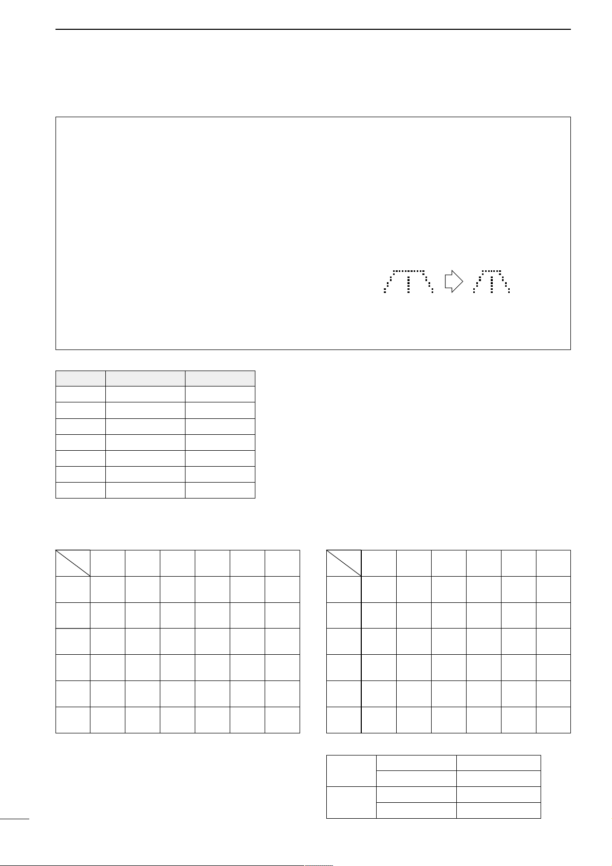
i
The explicit definitions described below apply to this
instruction manual.
WORD DEFINITION
RWARNING
Personal injury, fire hazard or electric
shock may occur.
CAUTION
Equipment damage may occur.
NOTE
If disregarded, inconvenience only. No risk
of personal injury, fire or electric shock.
Page 3

TABLE OF CONTENTS
IMPORTANT ............................................................. i
PRECAUTIONS ........................................................ i
EXPLICIT DEFINITIONS .......................................... i
TABLE OF CONTENTS ............................................ ii
UNPACKING ............................................................. ii
1 PANEL DESCRIPTION .....................................1–8
■ Front panel ............................................................... 1
■ Function switches ..................................................... 3
■ Rear and side panels ............................................... 5
■ Function display ....................................................... 7
■ Microphone (HM-103) ............................................... 8
2 INSTALLATION AND CONNECTIONS .......... 9– 14
■ Unpacking ................................................................. 9
■ Grounding ................................................................. 9
■ Antenna .................................................................... 9
■ Installation ................................................................ 10
■ Required connections ............................................... 11
■ Advanced connections ............................................. 12
■ Power supply connections ........................................ 13
■ External antenna tuners and linear amplifier ............ 14
3 FREQUENCY SETTING................................ 15–19
■ When first applying power (CPU resetting) .............. 15
■ Initial settings ............................................................ 15
■ VFO description ........................................................ 16
■ Frequency setting ..................................................... 17
■ Mode selection ......................................................... 19
4 RECEIVE AND TRANSMIT .......................... 20– 38
■ Functions for receive ................................................ 20
■ Functions for transmit ............................................... 25
■ Split frequency operation .......................................... 29
■ Tone squelch operation ............................................ 31
■ Tone scan operation ................................................. 31
■ One-touch repeater .................................................. 32
■ Auto repeater function .............................................. 32
■ Functions for CW ...................................................... 33
■ Functions for RTTY .................................................. 35
■ Packet operation ...................................................... 37
■ SWR ......................................................................... 38
5 MEMORY AND SCAN OPERATION ............ 39–44
■ Memory channels ..................................................... 39
■ Memory channel selection ........................................ 39
■ Memory clearing ....................................................... 39
■ Memory/call programming ........................................ 40
■ Frequency transferring ............................................. 41
■ Memory names ......................................................... 41
■ Memo pads ............................................................... 42
■ Scan types ................................................................ 43
■ Preparation .............................................................. 43
■ Programmed scan operation .................................... 44
■ Memory scan operation ............................................ 44
■ Select memory scan operation ................................. 44
■ Priority watch ............................................................ 44
6 REMOTE JACK (CI-V) INFORMATION ........ 45–46
7 SET MODE .................................................... 47–55
■ General ..................................................................... 47
■ Quick set mode items ............................................... 48
■ Initial set mode items ............................................... 50
8 MAINTENANCE ................................................... 56
■ Fuse replacement ..................................................... 56
■ Memory backup ........................................................ 56
■ Cleaning ................................................................... 56
9 TROUBLESHOOTING .................................. 57– 58
10 OPTIONAL INSTALLATIONS/SETTINGS .. 59–62
■ Opening the transceiver case ................................... 59
■ UT-102
VOICE SYNTHESIZER UNIT
............................... 59
■ CR-282
HIGH-STABILITY CRYSTAL UNIT
........................ 60
■ IF filters ..................................................................... 60
■ UT-106
DSP RECEIVER UNIT
....................................... 61
■ MB-72
CARRYING HANDLE
.......................................... 61
■ AT-180 internal switch description ............................ 62
11 INTERNAL VIEWS ............................................. 63
12 OPTIONS .................................................... 64– 65
13 SPECIFICATIONS ............................................. 66
14 MENU GUIDE ..............................................67–68
ii
UNPACKING
Accessories included with the IC-706MKIIG:
Qty.
q DC power cable* ....................................................1
w Hand microphone (HM-103)...................................1
e Spare fuse (30 A) ...................................................2
r Spare fuse (4 A) .....................................................1
t RTTY key plug........................................................1
y Electronic keyer plug ..............................................1
u ACC cable ..............................................................1
i Ferrite bead** .........................................................1
*OPC-639 for Europe versions (differs from the diagram at
left), OPC-025D for other versions.
**Not supplied with some versions.
q
w
er
yt
u
i
Page 4
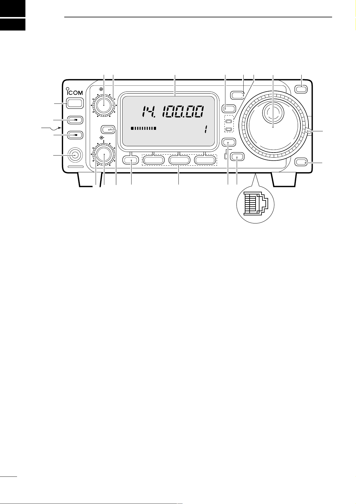
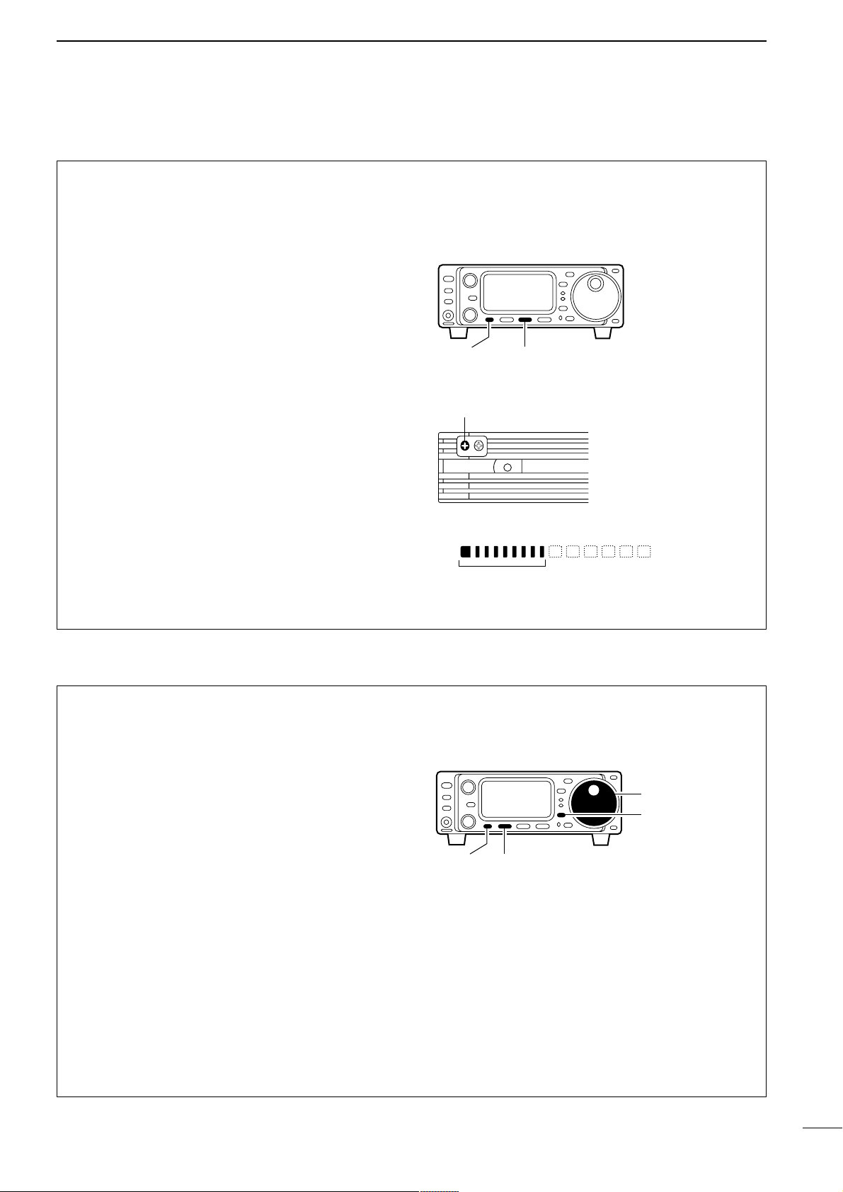
■ Front panel
q POWER SWITCH [POWER] (p. 15)
Turns power ON and OFF.
• Push momentarily to turn power ON.
• Push for 2 sec. to turn power OFF.
w AF GAIN CONTROL [AF] (inner control; p. 15)
Rotate clockwise to increase the audio output from
the speaker; rotate counterclockwise to decrease
the audio output from the speaker.
e RF GAIN CONTROL/SQUELCH CONTROL
[RF/SQL] (outer control; p. 22)
➥ Adjusts the squelch threshold level (to mute noise
when receiving no signal) in all modes.
➥ This control can be used for RF gain control to
adjust receiver gain manually.
• RF gain selection can be set in initial set mode (p. 50).
• RF gain is usable in SSB/CW/RTTY modes only.
r FUNCTION DISPLAY
Shows the operating frequency, dot matrix indications, selected memory channel, etc. See p. 7 for
details.
t TUNING STEP SWITCH [TS] (pgs. 17, 18)
➥ Push momentarily to cycle between 1 Hz/10 Hz,
programmable and 1 MHz tuning steps.
• 1 and 10 Hz steps are only available in SSB, CW and
RTTY modes; 1 MHz steps are only available in FM,
WFM and AM modes.
➥ Push for 2 sec. to toggle between 1 and 10 Hz
steps, or; when the programmable tuning steps is
indicated, push for 2 sec. to enter programmable
tuning step mode.
y MODE SWITCH [MODE] (p. 19)
➥ Push momentarily to cycle through the operating
modes:
USB/LSB ➧ CW/CWå ➧ RTTY/åRTTY ➧
➧ FM/WFM/AM
➥ Push and hold for 2 sec. to toggle between the
following operating modes:
USB ↔ LSB
CW ↔ CWå
RTTY↔ åRTTY
FM → WFM → AM → FM, etc.
u
RECEIVE/TRANSMIT INDICATORS [RX]/[TX]
[RX] lights green while receiving (and squelch
opens); [TX] lights red while transmitting.
i MAIN DIAL
Changes the displayed frequency, selects initial set
mode items, etc.
o UP/DOWN (BAND) SWITCHES [Y/Z(BAND)]
➥ Push to select a band.
• Can also be used to advance quick set mode items,
initial set mode items, etc.
➥ Push and hold to scroll through the bands contin-
uously.
!0 MAIN DIAL TENSION LATCH
Selects the main dial tension.
• 2 positions are available.
!1 MICROPHONE CONNECTOR (p. 8)
Modular-type microphone connector—connects the
supplied microphone (HM-103).
• The optional OPC-589 can be used to connect an 8-pin
microphone such as the SM-8 or SM-20, if desired.
• A microphone connector is also available on the rear
1
1
PANEL DESCRIPTION
HF/VHF/UHF TRANSCEIVER
i706MK™G
AF
RIT/
SUB
MENU F-1 F-2 F-3
MODE
BAND
BAND
Y
Z
TS
DISPLAY
LOCK
RX
TX
M-CH
PHONES
TUNER/CALL
P.AMP/ATT
POWER
SHIFT
RF/SQL
q
w e
r
t
y
i
o
o
!1
!2!3!4!5!6!7!8
!9
@0
@2
@1
!0
u
CH
VFO A
P
O
S1
5
537920401060dB
USB
M1
SPL
A/B A=B
Page 5
2
1
PANEL DESCRIPTION
panel. DO NOT connect 2 microphones simultaneously.
!2 LOCK SWITCH [LOCK]
➥ Push momentarily to turn the dial lock function
ON and OFF.
• The dial lock function electronically locks the main
dial.
➥ When the optional UT-102
VOICE SYNTHESIZER
UNIT
is installed (p. 52), push for 2 sec. to have
the frequency, etc. announced.
• UT-102 operation can be adjusted in initial set mode
(pgs. 53, 54).
!3 DISPLAY SWITCH [DISP] (p. 68)
➥ Push momentarily to select one of the three menu
sets: M1 to M4, S1 to S4 and G1 to G4.
➥ Push for 2 sec. to select quick set mode.
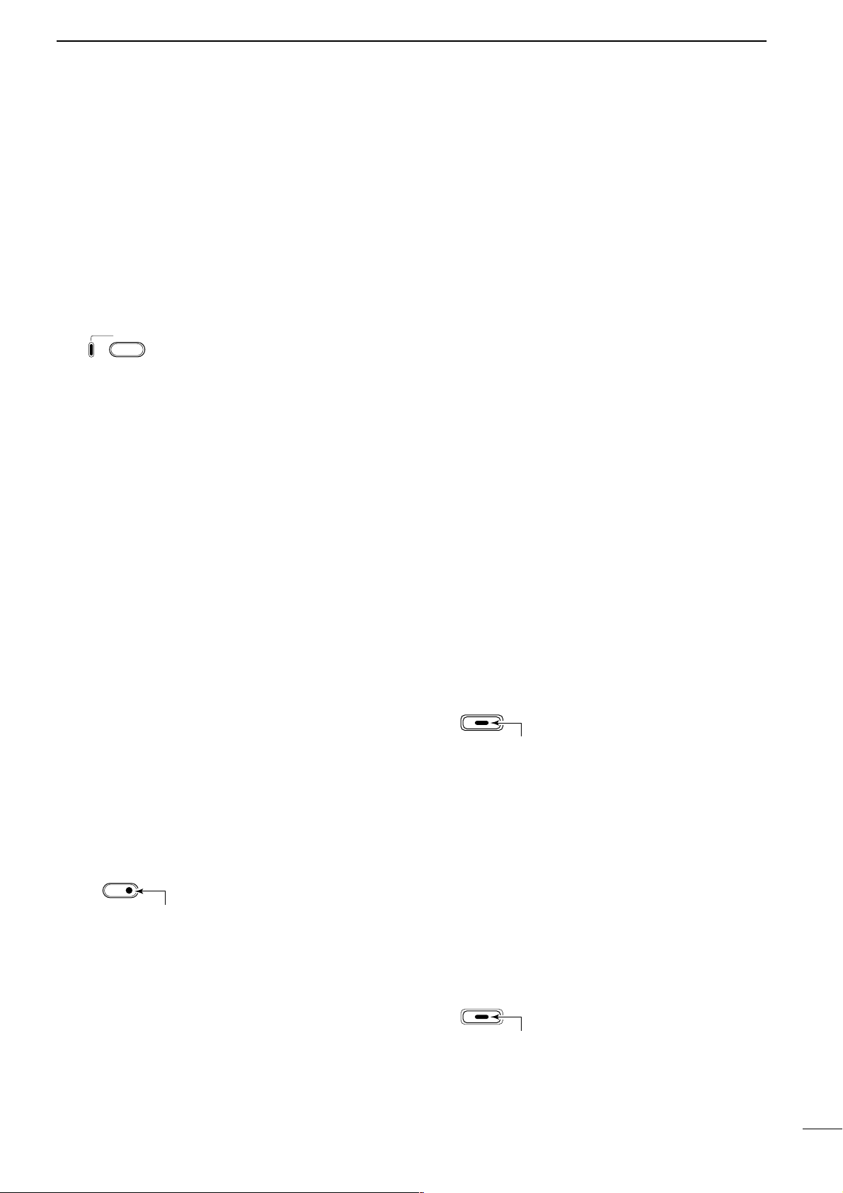
!4 FUNCTION SWITCHES [F1]/[F2]/[F3] (pgs. 3, 4, 68)
Push to select the function indicated in the dot
matrix display above these switches.
• Functions vary depending on the menu set selected.
!5 MENU SWITCH [MENU] (p. 68)
➥Push this switch one or more times to select
menus within a menu set (M, S or G), or push to
advance through the quick set mode and initial
set mode displays.
➥ Push and hold to jump between two different
function menu sets.
!6 RIT/SUB DIAL SWITCH [RIT/SUB] (p. 20)
➥ Push to toggle the RIT or SUB DIAL function ON
and OFF—initial set mode is used to select the
desired action*.
• Lights green when the SUB DIAL function is ON;
lights red when the RIT function is ON.
• Use the [M-CH] control to vary the RIT frequency or
SUB DIAL frequency (see above).
➥ When the RIT function is ON, push for 2 sec. to
add or subtract the shifted frequency to the operating frequency.
*Even if RIT is selected in initial set mode, RIT cannot be
selected when operating AM, FM or WFM modes.
!7 SHIFT CONTROL [SHIFT] (outer control; p. 20)
Shifts the center frequency of the receiver’s IF passband.
• Rotate the control clockwise to shift the center frequency higher, or rotate the control counterclockwise to shift
the center frequency lower.
• When the graphic menu display (
G2) is selected, the IF
passband is graphically displayed and changes in accordance with the [SHIFT] control (see p. 20).
!8 M-CH CONTROL [M-CH] (inner control)
➥
When the RIT or SUBDIAL functions are OFF,
rotate to select a memory channel number (p. 35).
➥ Shifts the receive frequency while the RIT func-
tion is ON in SSB, CW and RTTY modes (see
below and p. 20).
• RIT variable range is ± 9.99 kHz
➥ Changes the operating frequency in the selected
tuning steps while the SUB DIAL function is ON
(p. 18).
!9 HEADPHONE JACK [PHONES] (p. 12)
Accepts headphones with 4–16 Ω impedance.
• When headphones are connected, no receive audio
comes from the speaker.
• When the PHONES/SPEAKER switch on the back of the
front panel is set to the [SPEAKER] position, an external
speaker can be connected. This is convenient for mobile
or outdoor operation.
@0 TUNER/CALL SWITCH [TUNER/CALL]
(pgs. 26, 27)
➥ During HF/50 MHz operation, push this switch
momentarily to toggle the automatic antenna
tuner function ON/OFF.
• An optional antenna tuner must be connected.
➥ During HF/50 MHz operation, push this switch for
2 sec. to manually tune the antenna.
• An optional antenna tuner must be connected.
➥ During 144/430 MHz operation, push this switch
momentarily to select the call channel (or the previous channel/frequency when the call channel is
already selected). (p. 39)
•“C1” is the 144 MHz call channel and “C2” is the 430
MHz call channel.
@1
FRONT PANEL LATCH (p. 10)
Pull away from the transceiver (towards yourself
when looking at the front of the transceiver) to
detach the front panel from the main body of the
transceiver.
@2 P
REAMP/ATTENUATOR SWITCH [P.AMP/ATT]
(p. 21)
➥ Push momentarily to turn the preamp ON or OFF.
➥ Push and hold to turn the 20 dB attenuator ON;
push momentarily to turn the attenuator OFF.
• Lights green when the preamp is ON; lights red when
the 20 dB attenuator is ON.
LOCK
Lights while the lock
function is activated.
RIT
SUB
Lights red while the RIT function is activated;
green while the SUB DIAL function is activated.
TUNER/CALL
Lights while the automatic
tuning function is activated.
P.AMP/ATT
Lights green while the preamp is activated;
lights red while the attenuator is activated.
Page 6
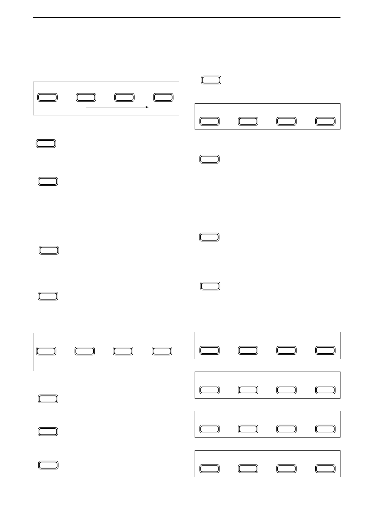
■ Function switches
D M1 FUNCTIONS
SPLIT OPERATION (p. 29)
Toggles the split function ON and OFF.
•“ä”appears when the split function is ON.
• The function of [F-3] changes to XFC when the
split function is ON.
VFO A/B SELECTION (p. 16)
➥ Toggles between VFO A and VFO B in
VFO mode.
➥ Toggles between transmission VFO and
reception VFO during split operation.
➥ Toggles between the transmit and
receive frequencies (and modes) of
memory channels when the split function is turned ON.
VFO EQUALIZATION (p. 16)
Equalizes the frequency and operating
mode of the two VFO’s.
• The rear (undisplayed) frequency and operating mode are equalized to the front (displayed)
VFO frequency and operating mode.
TRANSMIT FREQUENCY CHECK (p. 29)
Appears when the split function is turned
ON—monitors the transmit frequency
when pushed and held.
• While pushed, the transmit frequency can be
changed with the main dial.
D M2 FUNCTIONS
MEMORY WRITE (p. 40)
Stores the displayed frequency and operating mode into the displayed memory
channel.
MEMORY TRANSFER (p. 41)
Transfers the frequency and operating
mode in the selected memory channel to a
VFO.
VFO/MEMORY (p. 39)
Toggles between VFO and memory
modes.
MEMORY CLEAR (p. 39)
Clears the selected memory channel’s
contents.
•“}” appears.
D M3 FUNCTIONS
NARROW FILTER (p. 23)
Toggles the narrow filter (or wide filter—
push for 2 sec.) ON and OFF.
•“ã”appears when the narrow filter is ON; “ç”
appears when the wide filter is ON.
• An optional narrow filter and presetting in initial
set mode (p. 51) is necessary to use the following:
CW/RTTY narrow: FL-100, FL-101 or FL-232
SSB narrow: FL-223
SSB wide: FL-103
NOISE BLANKER (p. 21)
Turns the noise blanker ON and OFF.
• The noise blanker does not function in FM and
WFM modes; the “AM Noise blanker” item in
initial set mode must be set to ON for the noise
blanker to work in AM mode (p. 53).
METER SELECTION (p. 25)
Selects the type of meter displayed (during
transmit) in the function display.
• Power, ALC or SWR metering can be selected.
• Only an S-meter is available for receive.
D M4 FUNCTIONS
DURING SSB/AM OPERATION:
DURING CW OPERATION:
DURING RTTY OPERATION:
DURING FM OPERATION:
F-3
MET
F-2
NB
F-1
FIL
F-2
MCL
F-3
V/M
F-2
MÜV
F-1
MW
F-3
XFC
F-3
A=B
F-2
A/B
F-1
SPL
3
1
PANEL DESCRIPTION
MENU
M3
F-1
FIL
F-2
NB
F-3
MET
MENU
M4
F-1
VOX
F-2
COM
F-3
AGC
MENU
M4
F-1 F-2
BRKi/4
F-3
AGC
MENU
M2
F-1
MW
F-2
MÜV
MCL
F-3
V/M
(in memory mode)
MENU
M4
F-1
1/4
F-2 F-3
AGC
MENU
M4
F-1
VOX
F-2
TSQ
F-3
TON
MENU
M1
F-1
SPL
F-2
A/B
XFC
F-3
A=B
Page 7
4
1
PANEL DESCRIPTION
VOX FUNCTION (p. 26)
Toggles the VOX function ON and OFF.
• The [VOX GAIN] and [ANTI VOX] are available on the side panel.
• VOX delay can be set in quick set mode
(p. 48).
SPEECH COMPRESSOR (p. 26)
Toggles the speech compressor ON and
OFF.
• The [COMP GAIN] control is available on the
side panel.
AGC (p. 21)
Changes the time constant of the AGC circuit.
BREAK-IN (p. 33)
Selects semi break-in, full break-in (QSK)
and break-in OFF
•“BK” or “F-BK” appears when selecting semi
break-in or full break-in, respectively.
• An external switch, such as a foot switch, is
necessary to connect to the ACC socket (pin 3,
pin 7 or RTTY SEND—see p. 35) to use no
break-in operation.
1/4 FUNCTION (p. 36)
Toggles the 1/4 function ON and OFF.
• When the 1⁄4 function is ON, a bar appears
under the
1
⁄4 indication and fine tuning can be
used.
TONE SQUELCH (p. 31)
Toggles the tone squelch function ON and
OFF (a tone squelch frequency must be
selected in Quick Set mode).
•“FM-TSQL” appears when the function is ON.
REPEATER TONE OPERATION (p. 30)
➥ Toggles the subaudible tone encoder for
repeater use ON and OFF.
•“FM-T” appears when the function is ON.
➥ Transmits a 1750 Hz tone burst when
pushed and held during transmission.
• Tone frequencies or tone burst can be set in
initial set mode (p. 49).
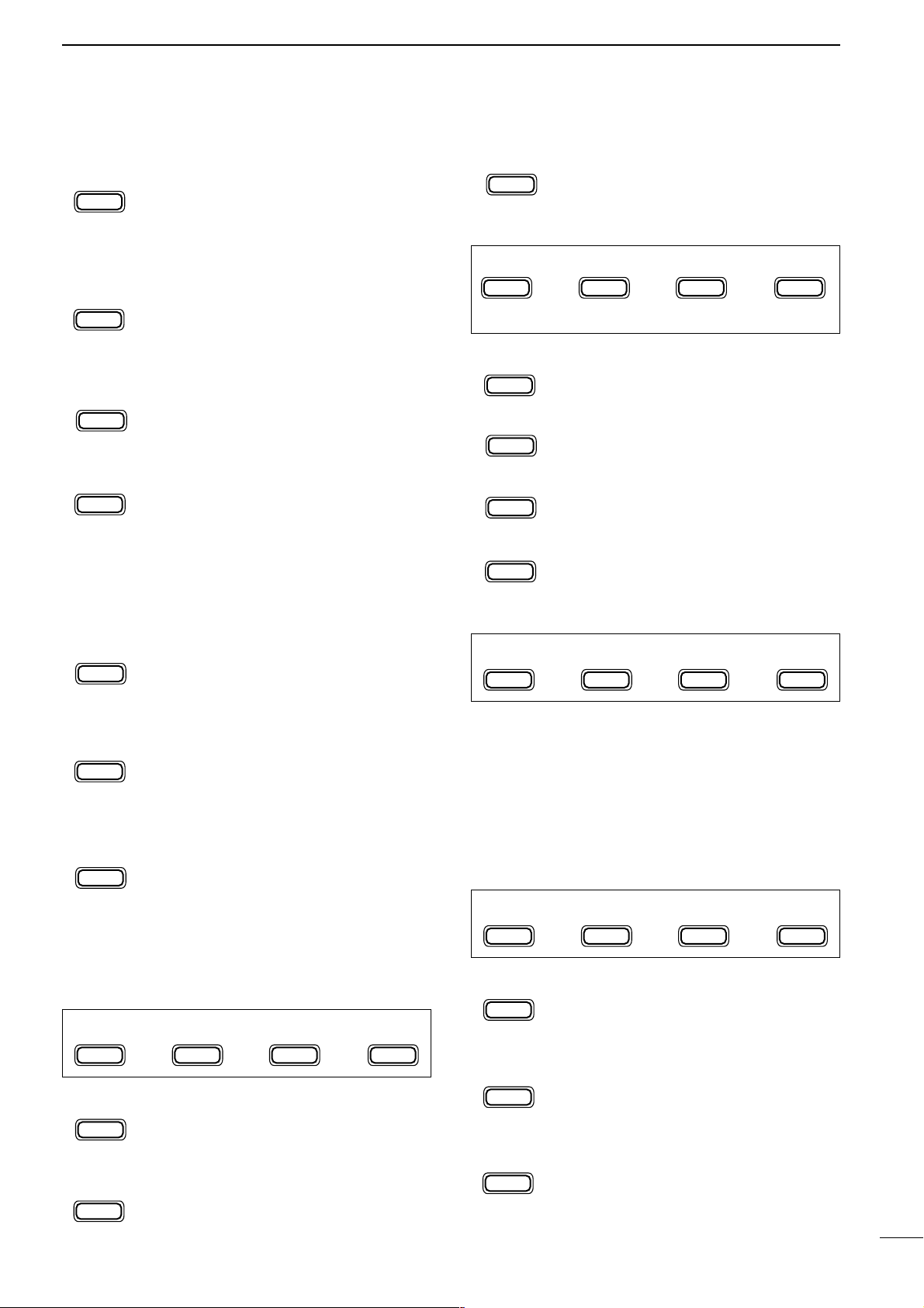
D S1 FUNCTIONS
MEMORY WRITE (p. 40)
Stores the displayed frequency and operating mode into the displayed memory
channel.
MEMO PAD WRITE (p. 42)
Stores the displayed frequency and operating mode into a memo pad.
MEMO PAD READ (p. 42)
Calls up a memo pad.
D S2 FUNCTIONS
SCAN (p. 44)
Starts and stops the scan function.
PRIORITY WATCH (p. 44)
Starts and stops priority watch.
SELECT SCAN (p. 44)
Toggles the select setting ON and OFF for
the selected memory channel.
VFO/MEMORY (p. 44)
Toggles between VFO and memory
modes.
D S3 FUNCTIONS
QUICK BAND CHANGE FUNCTION (p. 19)
This item provides access to the band stacking register. By default the 7, 50 and 144 MHz bands are displayed. Push [F-1] to [F-3] for 2 sec. to select a new
band if desired.
• A mode is memorized along with the frequency for each
band.
D S4 FUNCTIONS (may be optional for some ver.)
AUTOMATIC NOTCH FILTER (p. 24)
This function automatically attenuates beat
tones, tuning signals, etc., even if they are
moving.
NOISE REDUCTION (p. 24)
This function reduces noise components
and picks out desired signals which are
buried in the noise.
NOISE REDUCTION DISPLAY (p. 24)
This displays the noise reduction level
when using the noise reduction function.
F-3
NRL
F-2
NR
F-1
ANF
F-3
V/M
F-2
SEL
F-2
PRI
F-1
SCN
F-3
MPR
F-2
MPW
F-1
MW
F-3
TON
F-2
TSQ
F-1
1/4
F-2
BRK
F-3
AGC
F-2
COM
F-1
VOX
MENU
S1
F-1
MW
F-2
MPW
F-3
MPR
MENU
S2
F-1
SCN
F-2
PRI
SEL
F-3
V/M
(in memory mode)
MENU
S3
F-1
7
F-2
50
F-3
144
MENU
S4
F-1
ANF
F-2
NR
F-3
NRL
Page 8
5
1
PANEL DESCRIPTION
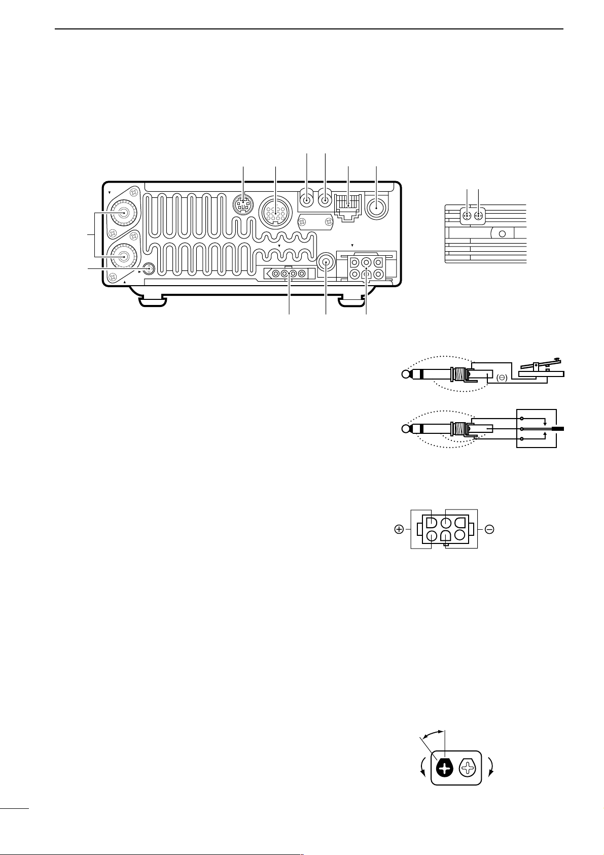
■ Rear and side panels
q GROUND TERMINAL [GND] (p. 9)
Connect this terminal to a ground to prevent electrical shocks, TVI, BCI and other problems.
w
ANTENNA CONNECTORS [ANT 1], [ANT 2] (p. 11)
Accept a 50 Ω antenna with an PL-259 type plug.
• [ANT 1] is for connection to an HF/50 MHz antenna.
• [ANT 2] is for connection to 144 MHz antenna.
• These connectors are switched above or below 60 MHz.
e
DATA JACK [DATA] (p. 12)
6-pin min DIN jack to connect a TNC, etc. for packet operation.
r
ACCESSORY SOCKET [ACC] (p. 6)
Enables connection to external equipment such as
a TNC for data communications, a linear amplifier or
an automatic antenna selector/tuner, etc.
• See page at right for socket information.
t
RTTY JACK [RTTY] (p. 35)
Connects an external terminal unit for RTTY (FSK)
operation.
• The keying polarity and mark/shift frequencies can be
selected in quick set mode (p. 48).
y CI-V REMOTE CONTROL JACK [REMOTE]
(p. 45)
Designed for use with a personal computer for
remote operation of transceiver functions.
u MICROPHONE CONNECTOR [MIC] (p. 11)
Accepts the supplied microphone (connected in parallel with the front panel’s [MIC] connector).
• See pgs. 1 and 2 for microphone notes.
• See p. 8 for microphone connector information.
i ELECTRONIC KEYER JACK [KEY] (p. 33)
Accepts a paddle to activate the internal electronic
keyer.
• Selection between the internal electronic keyer and
straight key operation can be made in quick set mode.
(p. 49)
o DC POWER SOCKET [DC13.8V] (p. 13)
Accepts 13.8 V DC through the supplied DC power
cable.
!0 EXTERNAL SPEAKER JACK [EXT SP] (p. 12)
Accepts a 4–16 Ω speaker.
!1 TUNER CONTROL SOCKET [TUNER] (p. 12)
Accepts the control cable from an optional AH-3
HF
AUTOMATIC ANTENNA TUNER
.
!2 SPEECH COMPRESSION LEVEL CONTROL
[COMP GAIN] (p. 26)
Adjusts the compression level.
• This control is available only when the speech compressor is ON.
COMP
GAIN /SIDE T
BEEP
DC 13.8V
EXT SP
MIC
KEY
TUNER
ANT 1
ANT 2
GND
q
w
er ui
o
!2 !3
!0!1
ty
When connecting
a straight key
When connecting
a paddle
(dot)
(com)
(dash)
(⊕)
Rear panel view
Recommended
level
Counterclockwise
decreases
Clockwise
increases
COMP
GAIN /SIDE T
BEEP
Page 9

• ACC SOCKET
• When connecting the ACC conversion cable (OPC-599)
6
1
PANEL DESCRIPTION
!3 BEEP/SIDETONE CONTROL [BEEP/SIDETONE]
Adjusts the beep tone and CW side tone audio levels.
TECHNICAL INFORMATION
ACC PIN # NAME DESCRIPTION SPECIFICATIONS COLOR
1 8 V Regulated 8 V output.
Output voltage : 8 V ±0.3 V
Output current : Less than 10 mA
brown
2 GND Connects to ground. red
3 HSEND
Input/output pin (HF/50 MHz).
Goes to ground when transmitting.
When grounded, transmits (connected to 8V
line thru 2.2 kΩ resistance/144 MHz operation)
.
Ground level :–0.5 V to 0.8 V
Input current : Less than 20 mA
(HF/50 MHz bands)
orange
4 BDT Data line for the optional AT-180. yellow
5 BAND
Band voltage output.
(Varies with amateur band)
Output voltage : 0 to 8.0 V green
6 ALC ALC voltage input.
Control voltage : –4 to 0 V
Input impedance : More than 10 kΩ
blue
7 VSEND
Input/output pin (144 MHz).
Goes to ground when transmitting.
When grounded, transmits
(connected to 8V
line thru 2.2 kΩ resistance/HF•50 MHz operation)
.
Ground level :–0.5 V to 0.8 V
Input current : Less than 20 mA
(144 MHz band)
purple
8 13.8 V 13.8 V output when power is ON. Output current : Max. 1 A gray
9 TKEY Key line for the AT-180. white
10 FSKK
RTTY keying input.
Connected in parallel to the [RTTY] jack.
Ground level :–0.5 to 0.8 V
Input current : Less than 10 mA
black
11 MOD Modulator input.
Input impedance :10 kΩ
Input level :Approx. 100 mV
rms
pink
12 AF
AF detector output.
Fixed, regardless of [AF] position.
Output impedance : 4.7 kΩ
Output level : 100 to 350 mV rms
light
blue
13 SQLS
Squelch output.
Goes to ground when squelch opens.
SQL open :Less than 0.3 V/5 mA
SQL closed : More than 6.0 V/100 µA
light
green
Rear panel
view
1234
8765
9
10 11 12
13
Color refers to the
cable strands of the
supplied cable.
ACC 1
ACC 2
➀ FSKK ➄ AF
➁ GND ➅ SQLS
➂ HSEND ➆ 13.8 V
➃ MOD ➇ ALC
➀ 8 V ➄ ALC
➁ GND ➅ VSEND
➂ HSEND ➆ 13.8 V
➃ BAND
1122334
4
8877665
5
9
10 11 12
13
1
2
3
4
76
5
Page 10
7
1
PANEL DESCRIPTION
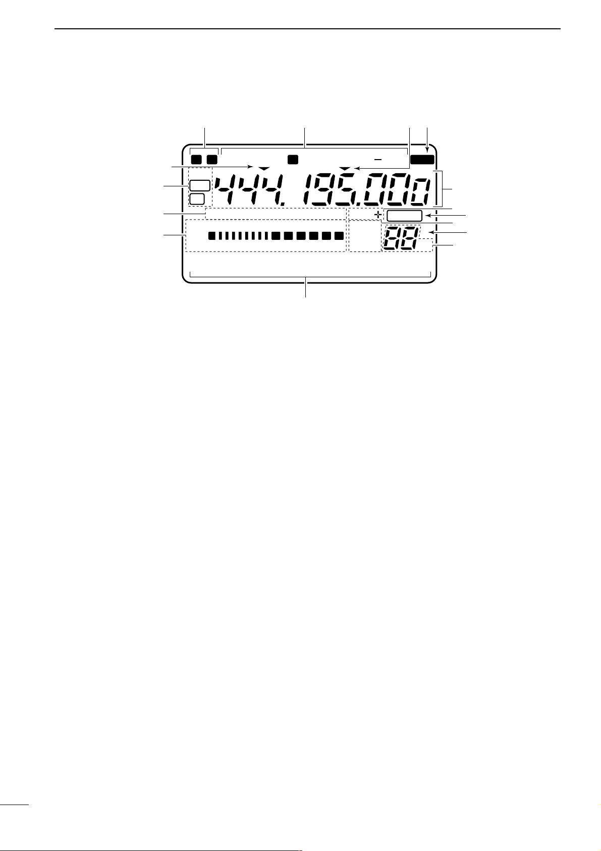
■ Function display
q NARROW/WIDE FILTER INDICATORS
➥ “ã” appears when selecting AM narrow or FM
narrow modes.
➥ When installing an optional narrow filter, narrow
mode can be selected in CW, RTTY and SSB
modes.
• When the SSB wide filter is installed, “ç” appears
during wide mode selection.
w MODE INDICATORS
Show the operating mode.
e PROGRAMMABLE/1 MHz TUNING STEP
INDICATORS
➥➌a appears when the programmable tuning step
is selected.
➥➌b appears when the 1 MHz tuning step is
selected.
r SPLIT INDICATOR
Shows that the split frequency function is activated.
t FREQUENCY READOUT
Shows the operating frequency.
•“C” appears in place of the 1 Hz digit when the call chan-
nel is selected.
y DUPLEX INDICATORS
➥ “DUP+” appears during plus duplex operation.
➥ “DUP–” appears during minus duplex operation.
u BLANK INDICATOR
Shows that the displayed memory channel is not
programmed.
• This indicator appears both in VFO and memory modes.
i VFO/MEMORY INDICATORS
VFO A or B appears when VFO mode is selected;
MEMO appears when memory mode is selected.
o SELECT INDICATOR
Shows that the displayed memory channel is designated as a select memory channel.
!0 MEMORY CHANNEL NUMBER READOUT
Shows the selected memory channel number.
!1 DOT MATRIX INDICATORS
These alphanumeric readouts show a variety of
information such as current functions of the “F” keys
[F1] to [F3], memory channel names, set mode
items, etc. See p. 68 for an overview of these indicators.
!2 METER READOUTS
➥ Functions as an S-meter while receiving.
➥ Functions as a power, ALC or SWR meter while
transmitting.
Note: The SWR meter does not function in the 144
MHz band.
!3 FUNCTION INDICATORS
➥ “NB” appears when the noise blanker is activat-
ed.
➥ “VOX” appears when the VOX function is select-
ed.
➥ “F-BK” appears when full break-in operation is
selected and only “BK” appears when semi
break-in operation is selected.
➥ “COM” appears when the speech compressor is
activated.
➥ “FAGC” appears when the fast AGC function is
selected.
!4 DSP INDICATORS
Appear when the optional DSP unit is installed and
activated.
N W R SPL
LSB
DSP
NB VOX F-BK COM F
S
CH
VFO A
DUP
VFO B
MEMO
AGC
ALC
SWR PO
S1
1 1.5 2 3 5
53792040
10
∞
60dB
USB CW RTTY
AM WFM TSQL
BLANK
ANF
NR
qw r
t
y
u
o
!1
!2
!3
!4
i
!0
ea
eb
M1
SPL
A/B
A=B
Page 11
• MICROPHONE CONNECTOR
8
1
PANEL DESCRIPTION
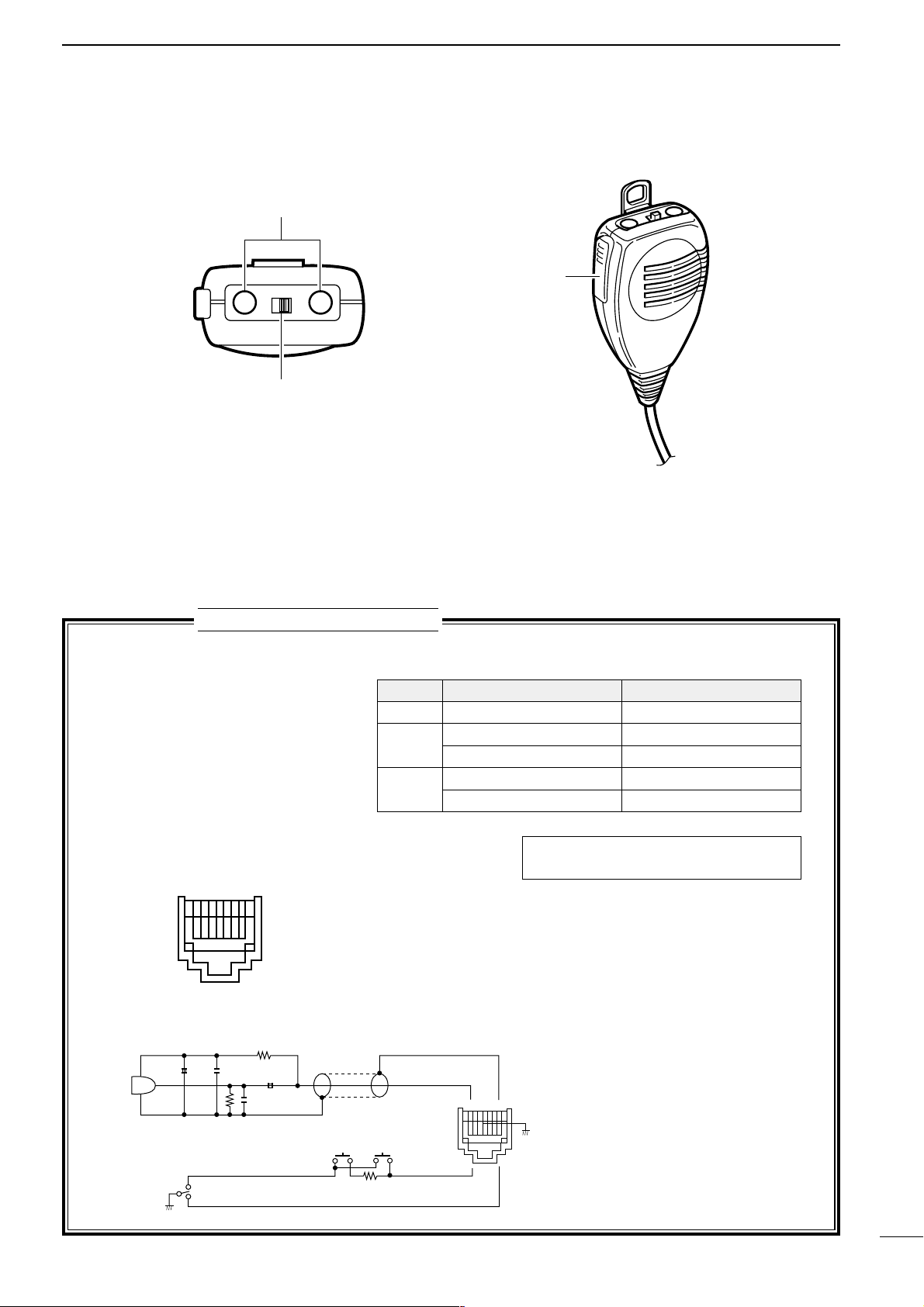
■ Microphone (HM-103)
➊ UP/DOWN SWITCHES [UP]/[DN]
Change the operating frequency.
• Push and hold to change the frequency continuously.
• Tuning step is 50 Hz when no TS indicator appears.
➋ LOCK SWITCH [LOCK]
Locks the [UP]/[DN] switches.
➌ PTT SWITCH [PTT]
Push and hold to transmit; release to receive.
TECHNICAL INFORMATION
PIN NO. FUNCTION DESCRIPTION
1 +8 V DC output Max. 10 mA
2
Frequency up Ground
Frequency down Ground through 470 Ω
8
Squelch open “LOW” level
Squelch closed “HIGH” level
➃ PTT
➅ Microphone input
➁ Frequency up/down
➆ GND
➀ +8 V DC output
➇ Squelch switch
➄ GND (microphone ground)
➂ AF output
Rear panel view
1 2345 678
• HM-103 SCHEMATIC DIAGRAM
4700p
4700p
10µ
0.33µ
+
+
MICROPHONE
MIC
ELEMENT
2k
2.2k
470
DOWN UP
PTT
RECEIVE
TRANSMIT
MICROPHONE
CABLE
MICROPHONE PLUG
12345678
Caution: DO NOT short pin 1 to ground as
this can damage the internal 8 V regulator.
➊
LOCK
DN UP
OFF ON
➋
➌
Page 12
9
2
INSTALLATION AND CONNECTIONS
■ Unpacking
After unpacking, immediately report any damage to
the delivering carrier or dealer. Keep the shipping cartons.
For a description and a diagram of accessory equipment included with the IC-706MKIIG, see UNPACKING on p. ii of this manual.
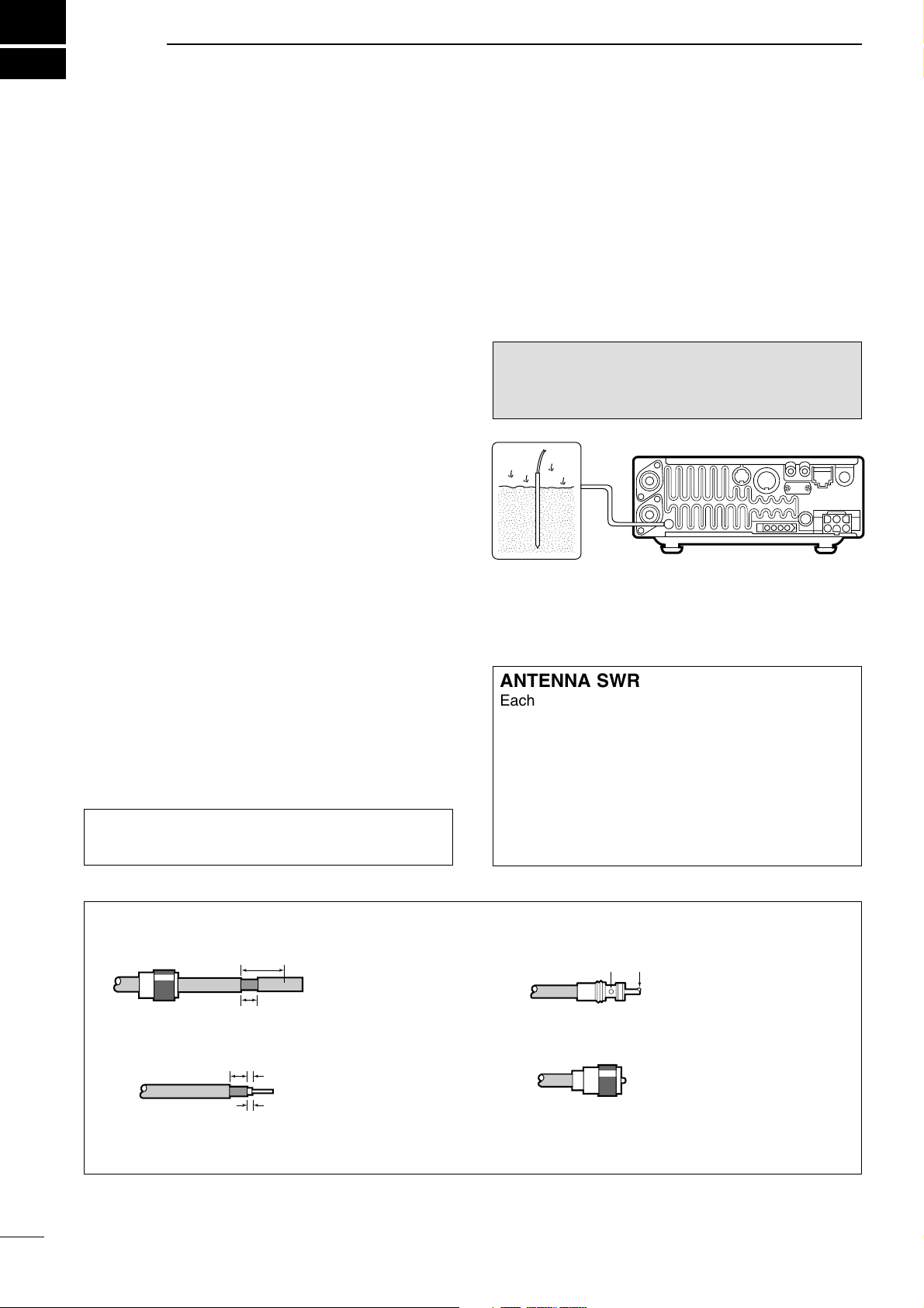
■ Grounding
To prevent electrical shock, television interference
(TVI), broadcast interference (BCI) and other problems, ground the transceiver through the GROUND
terminal on the rear panel.
For best results, connect a heavy gauge wire or strap
to a long earth-sunk copper rod. Make the distance
between the GROUND terminal and ground as short
as possible.
■ Antenna
Select antenna(s), such as a well-matched 50 Ω
antenna, and feedline. The transmission line should
be a coaxial cable. 1.5 : 1 or better of Voltage
Standing Wave Ratio (VSWR) is recommended for
your required band. Of course, the transmission line
should be a coaxial cable.
CAUTION: Protect your transceiver from lightning
using a lightning arrestor.
RWARNING: NEVER connect the [GND] ter-
minal to a gas or electric pipe, since the connection
could cause an explosion or electric shock.
30 mm
10 mm (soft solder)
10 mm
1–2 mm
solder solder
Soft
solder
Coupling ring
PL-259 CONNECTOR INSTALLATION EXAMPLE
➀➂
➃
➁
Slide the coupling ring
down. Strip the cable
jacket and soft solder.
Slide the connector
body on and solder it.
Screw the coupling ring
onto the connector
body.
Strip the cable as
shown at left. Soft
solder the center conductor.
(10 mm ≈
3
⁄8 in)
;
;
ANTENNA SWR
Each antenna is tuned for a specified frequency
range and SWR may be increased out-of-range.
When the SWR is higher than approx. 2.0 : 1, the
transceiver’s power drops to protect the final transistors. In this case, an optional antenna tuner is useful
to match the transceiver and antenna. Low SWR
allows full power for transmitting even when using
the antenna tuner. The IC-706MKIIG has an SWR
meter to monitor the antenna SWR continuously.
;;
;;
Page 13
To raise the stand:
With the transceiver upside down, pull the stand
towards the rear panel and then upwards, as illustrated below.
10
2
INSTALLATION AND CONNECTIONS
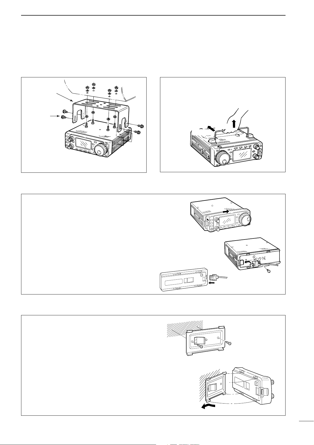
■ Installation
D Single body mounting D Stand
*CAUTION: Non-supplied screws (longer than 8 mm)
may damage the internal units.
MB-62
(optional)
Supplied with
the MB-62*
Pull back
then up
D Front panel separation
D Front panel mounting
➀ While pulling the panel release button towards you,
slide the front panel to the right (fig. 1).
➁ Attach the optional OPC-581 to the main body and
tighten the supplied screw as in fig. 2.
➂ Attach the other end of the OPC-581 to the
detached front panel as in fig. 3.
➀ Attach the MB-63 to a flat surface using the two
supplied screws (fig. 1).
➁ Fix the detached front panel to the MB-63 as illus-
trated in fig. 2.
Be careful of the orientation of the MB-63, otherwise, the front panel may become attached in the
opposite direction.
fig. 1
fig. 2
fig. 3
fig. 1
fig. 2
Page 14
11
2
INSTALLATION AND CONNECTIONS
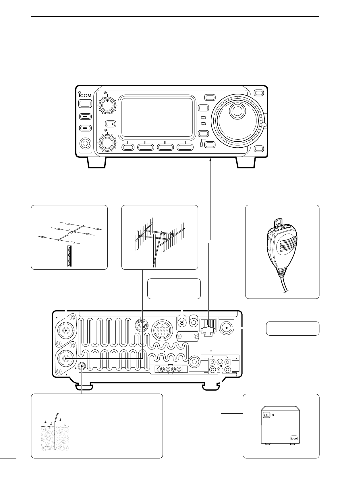
■ Required connections
DC 13.8V
EXT SP
MIC
KEY
TUNER
ANT 1
ANT 2
GND
HF/VHF/UHF TRANSCEIVER
i706MK™G
AF
RIT/
SUB
MENU F-1 F-2 F-3
MODE
Y
Z
TS
DISPLAY
LOCK
RX
TX
M-CH
PHONES
TUNER/CALL
P.AMP/ATT
POWER
SHIFT
RF/SQL
BAND
BAND
MICROPHONE (p. 8)
HF/50 MHz ANTENNA
RTTY TERMINAL
UNIT
(p. 35)
2 m ANTENNA
PS-85
GROUND
(p. 9)
HM-103
See p. 13 for details.
CW KEY (p. 33)
Use the heaviest gauge wire or
strap available and make the
connection as short as possible.
Grounding prevents electrical
shocks, TVI and other
problems.
Page 15
12
2
INSTALLATION AND CONNECTIONS
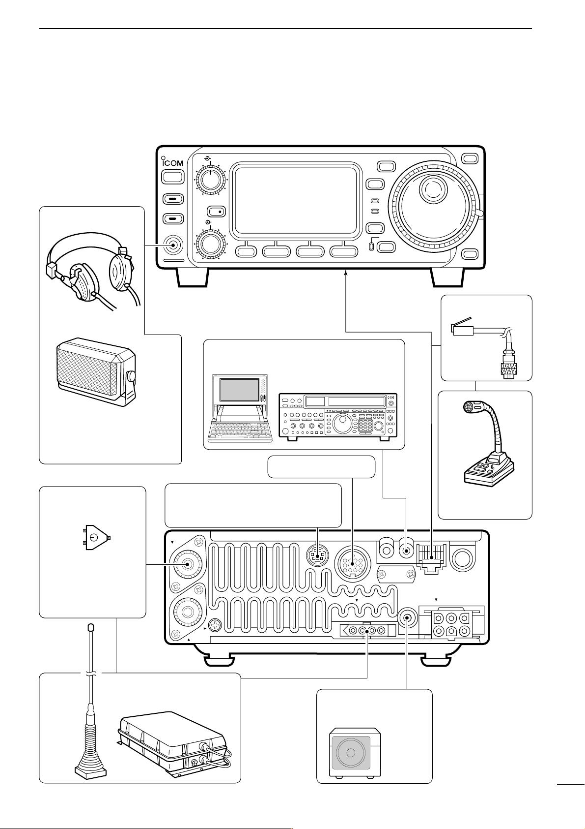
■ Advanced connections
DC 13.8V
EXT SP
MIC
KEY
TUNER
ANT 1
ANT 2
GND
OPC-589 (p. 65)
DESKTOP (p. 64)
MICROPHONE
SPEAKER
Selectable with the
[PHONE/SPEAKER] switch
on the back of the front panel.
ACC SOCKET (p. 6)
REMOTE
(p. 45)
Used for computer control and transceive.
DATA JACK
(p. 37)
6-pin mini DIN jack to connect to a
TNC, etc. for packet operation.
AH-3
(p. 14)
AH-2b
COAX ANTENNA
SWITCH
EXTERNAL
SPEAKER (p. 65)
HEADPHONES
SP-21
When using a 50 MHz
antenna separately
since the AH-3 can
only be used for the
HF bands.
or
HF/VHF/UHF TRANSCEIVER
i706MK™G
AF
RIT/
SUB
MENU F-1 F-2 F-3
MODE
Y
Z
TS
DISPLAY
LOCK
RX
TX
M-CH
PHONES
TUNER/CALL
P.AMP/ATT
POWER
SHIFT
RF/SQL
BAND
BAND
Page 16
CONNECTING THE PS-125 / PS-85 DC POWER SUPPLY
PS-125 / PS-85
Connect to an AC outlet
using the supplied AC cable.
DC power cable
DC power
socket
CONNECTING A NON-ICOM
DC POWER SUPPLY (For Europe versions)
Transceiver
DC power
socket
To non-Icom
power supply
[GND]
OPC-639
CONNECTING A NON-ICOM
DC POWER SUPPLY
Transceiver
DC power
socket
To AC outlet
Supplied
DC power cable
13.8 V
Black
30 A fuses
Red
20 A
13
2
INSTALLATION AND CONNECTIONS
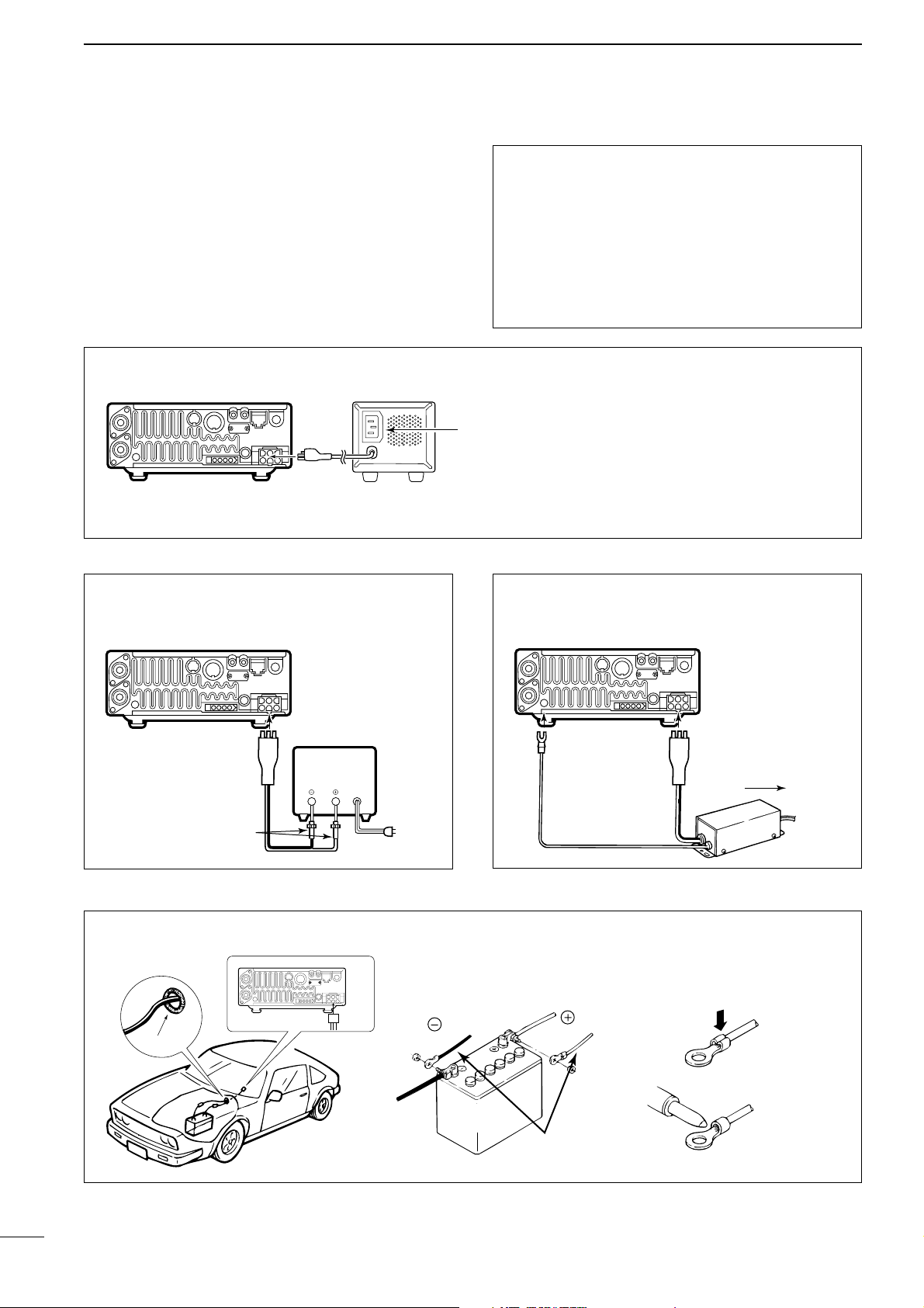
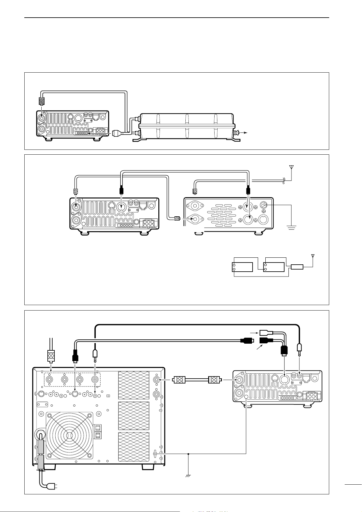
■ Power supply connections
Use the optional PS-125 / PS-85 DC POWER SUPPLY
when operating the IC-706MKIIG with AC power.
Refer to the diagram below for connection.
CAUTION: Before connecting the DC power
cable, check the following important items. Make
sure:
• The [POWER] switch is OFF.
• Output voltage of the power source is 12–15 V
when you use a non-Icom power supply.
• DC power cable polarity is correct.
Red : positive (+) terminal
Black : negative (–) terminal
Grommet
CONNECTING A VEHICLE BATTERY
NEVER
connect to
a 24 V battery.
Note: Use terminals for
the cable connections.
Crimp
Solder
Supplied
DC power cable
red
black
12 V
battery
Note: When using the PS-125, the IC706MKIIG Europe version complies with
EMC directives even if the OPC-639 is
not used.
Page 17
14
2
INSTALLATION AND CONNECTIONS
■ External antenna tuners and linear amplifier
AH-4
ANT 1
Transceiver
Coaxial cable
(from the AH-4)
To the AH-2b or
an antenna element
CONNECTING THE AH-4
The AH-4 can be used for the HF bands and 50
MHz band only.
CONNECTING THE AT-180
Ground
HF
to 6 m
antenna
[TRANSCEIVER]
[ANT 1] [ACC] [ACC]AT-180
ACC cable supplied with the AT-180
Coaxial cable supplied
with the AT-180
IC-706
one of two
connectors
ACC-1 REMOTE
INPUT-1 ANT1
ANT
Mini-plug cable
ACC cable
7-pin side
AC outlet (220–240 V)
IC-PW1
GND
GND
ACC REMOTE
Transceiver
Coaxial cable
To an
antenna
OPC-599 conversion cable
CONNECTING THE IC-PW1
Note:
• Turn the IC-706MKIIG’s power
OFF when connecting the AT180, otherwise, the CPU may
malfunction and the AT-180
may not function properly.
• The OPC-742 is required when
using
both the AT-180 and a 2
m linear amplifier.
Do not connect [ANT 2] to the
AT-180. When using an HF to 2 m
wide antenna, use a duplexer
between the AT-180 and antenna
since 2 m signals do not pass
through the AT-180.
[ANT 1]
Transceiver
Duplexer
HF to 2 m
antenna
AT-180
[ANT 2]
Page 18
15
3
FREQUENCY SETTING
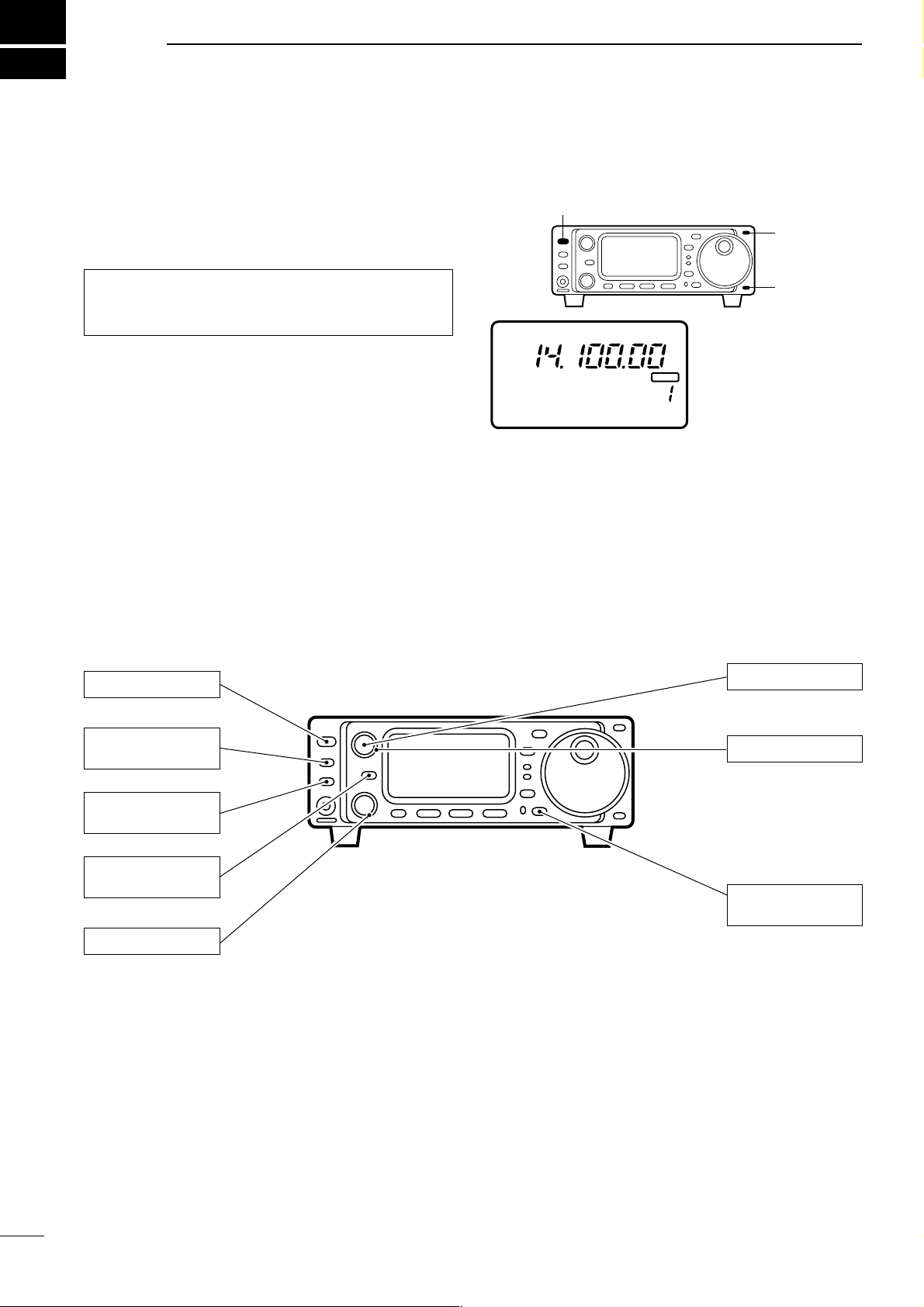
■ When first applying power (CPU resetting)
Before first applying power, make sure all connections
required for your system are complete by referring to
section 2. Then, reset the transceiver using the following procedure.
➀ Make sure the transceiver power is OFF.
➁ While pushing [Y] and [Z], push [POWER] to turn
power ON.
• The internal CPU is reset.
• The transceiver displays as shown at right when reset-
ting is complete.
D M1 display selection
If you can’t figure out how to return to the M1 display:
While pushing [MENU], turn power ON.
■ Initial settings
After resetting the transceiver, set controls and switches as shown in the diagram below.
Note: Resetting clears all programmed contents in
memory channels and returns all initial set mode and
quick set mode contents to their default values.
BLANK
CH
VFO A
S1
5379204060dB
USB
M1
SPL
A/B
A=B
The transceiver displays
its initial frequency and
mode.
[POWER]
[Y]
[Z]
PO 5
10
[AF]: Max. CCW
[RF/SQL]: Max. CCW
[LOCK]: OFF
(indicator light out)
[POWER]: OFF
[SHIFT]: Center
[P.AMP/ATT]: OFF
(indicator lights out)
[TUNER/CALL]: OFF
(indicator lights out)
[RIT/SUB]: OFF
(indicator lights out)
CCW: counterclockwise
Turn power ON, then check the display. If any of the
following indicators appear, turn them OFF as follows:
• Tuning step indicators,
Z
, (SSB, CW or RTTY):
Push [TS].
• MHz tuning step indicator, Z, (FM, WFM or AM):
Push [TS].
• 1 Hz frequency readout (SSB, CW or RTTY):
Push and hold [TS].
• Memory mode indicator, MEMO:
Use [(F-3)V/M] in the M2 display (p. 68).
• Split indicator, ä:
Use [(F-1)SPL] in the M1 display (p. 68).
Page 19
16
3
FREQUENCY SETTING
■ VFO description
VFO is an abbreviation of Variable Frequency
Oscillator, and traditionally refers to an oscillator. The
IC-706MKIIG’s VFO can store a frequency and an
operating mode.
You can call up a desired frequency to a VFO with the
memo pad-read switch (p. 42) or with the memory
transfer switch (p. 42). You can also change the frequency with the main dial and select an operating
mode with the [MODE] switch or call up previously
accessed frequency and modes with the band stacking register (p. 19).
The IC-706MKIIG has two VFOs, specially suited for
split frequency operation. The VFOs are called VFO A
and VFO B. You can use the desired VFO to call up a
frequency and operating mode for operation.
CH
VFO A
USB
M1
SPL
A/B
A=B
VFO
MODE
SWITCH
MEMORY
CHANNEL
DIAL
MEMO PAD
28.025 MHz
7.001 MHz
21.295 MHz
BAND
Select
Change
Transfer
Transfer
Transfer
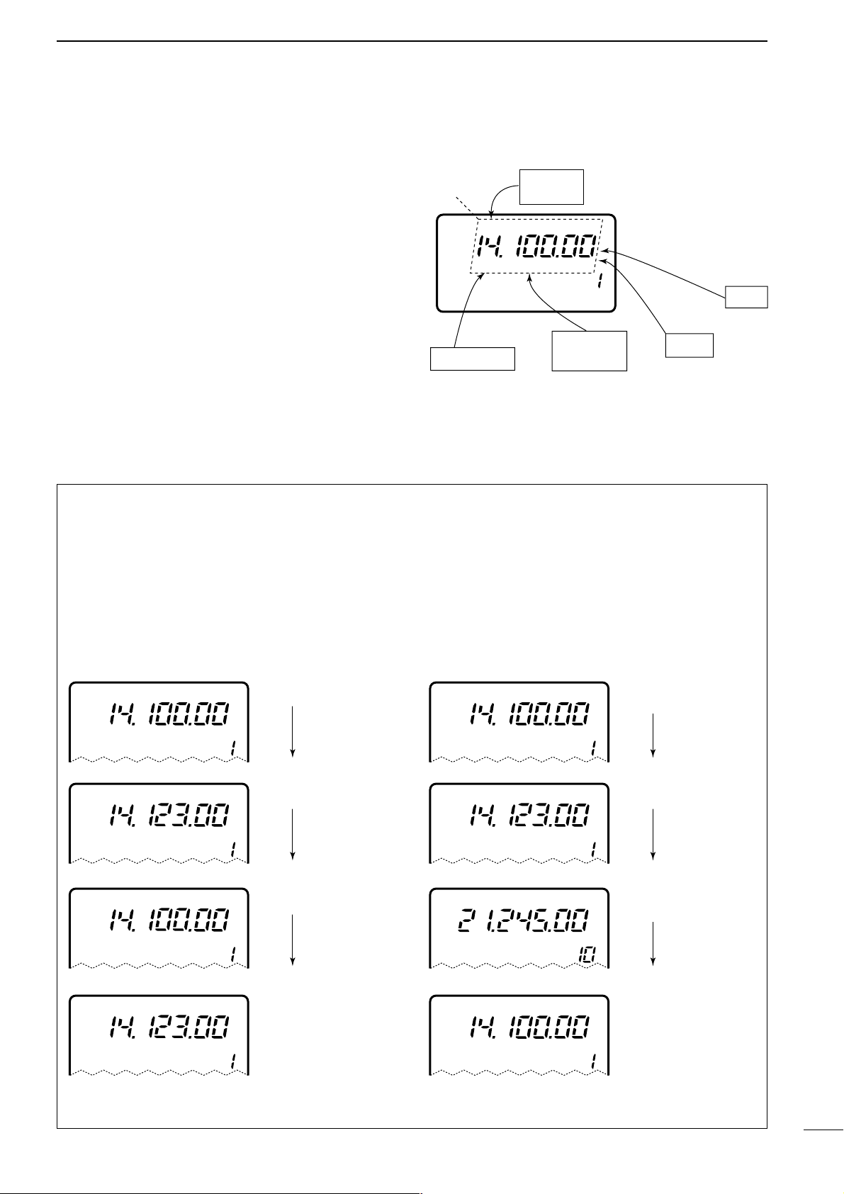
• The differences between VFO and memory mode
VFO MODE
Each VFO shows a frequency and operating mode. If
the frequency or operating mode is changed, the
VFO automatically memorizes the new frequency or
operating mode.
When the VFO is selected from another VFO or
memory mode, the last-used frequency and operating mode for that VFO appear.
[EXAMPLE]
MEMORY MODE
(pgs. 39–42)
Each memory channel shows a frequency and operating mode like a VFO. Even if the frequency or
mode is changed, the memory channel does not
memorize the new frequency or memory mode.
When a memory channel is selected from another
memory channel or VFO mode, the memorized frequency and operating mode appear.
[EXAMPLE]
CH
VFO A
USB
CH
VFO A
USB
VFO is selected.
The frequency is changed.
MEMO
CH
VFO A
USB
VFO is selected again.
Changed frequency (14.123 MHz) appears. Changed frequency (14.123 MHz) does not appear and
memorised frequency (14.100 MHz) appears instead.
CH
USB
Memory mode is selected.
CH
USB
CH
USB
Memory channel 1 is
selected.
The frequency is changed.
MEMO
MEMO
MEMO
MEMO
CH
USB
Memory channel 1 is
selected again.
CH
USB
Another memory channel
is selected.
Page 20
17
3
FREQUENCY SETTING
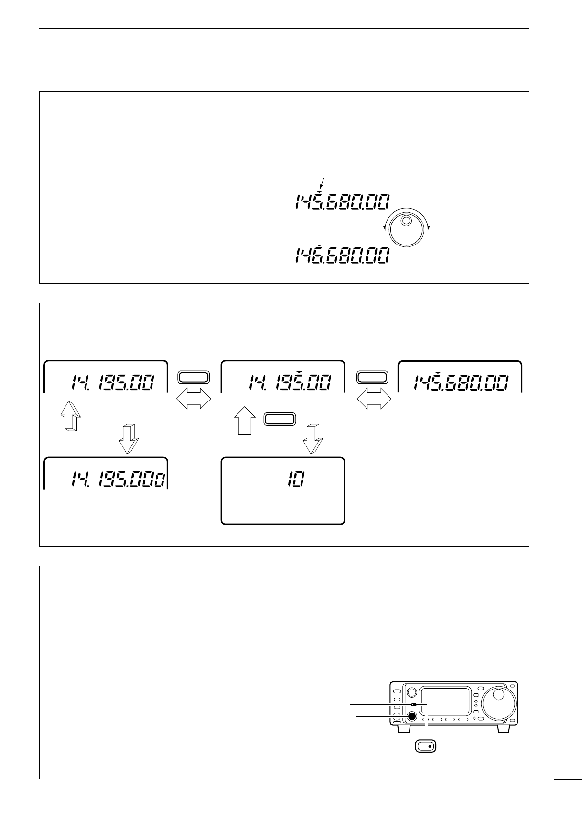
• Programmable tuning steps
Programmable tuning steps are available to suit your
operating requirements.
These tuning steps are:
• Independently selectable for each mode
• Selectable from 0.01 (FM/WFM/AM only), 0.1, 1, 5,
9, 10, 12.5, 15, 20 and 100 kHz
➀ Push [TS] one or more times until the programma-
ble tuning step indicator, “Z,” appears above the
1 kHz digit.
• Rotating the main dial changes the frequency according
to the set tuning step.
➁ Push [TS] for 2 sec. while the programmable tun-
ing step indicator appears to enter the tuning step
selection mode.
• Rotate DIAL appears.
➂ Rotate the main dial to set the desired tuning step.
• Change the mode and select tuning steps for other
modes, if desired.
➃ Push [TS] to exit the tuning step selection mode.
➄ Rotate the main dial to change the frequency
according to the set tuning step.
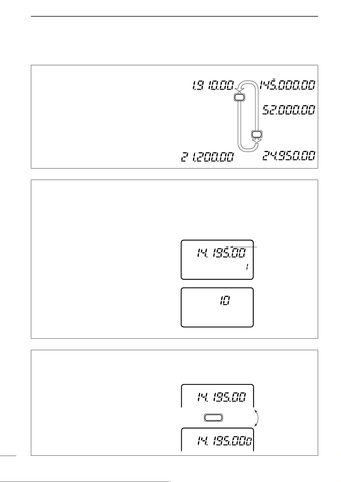
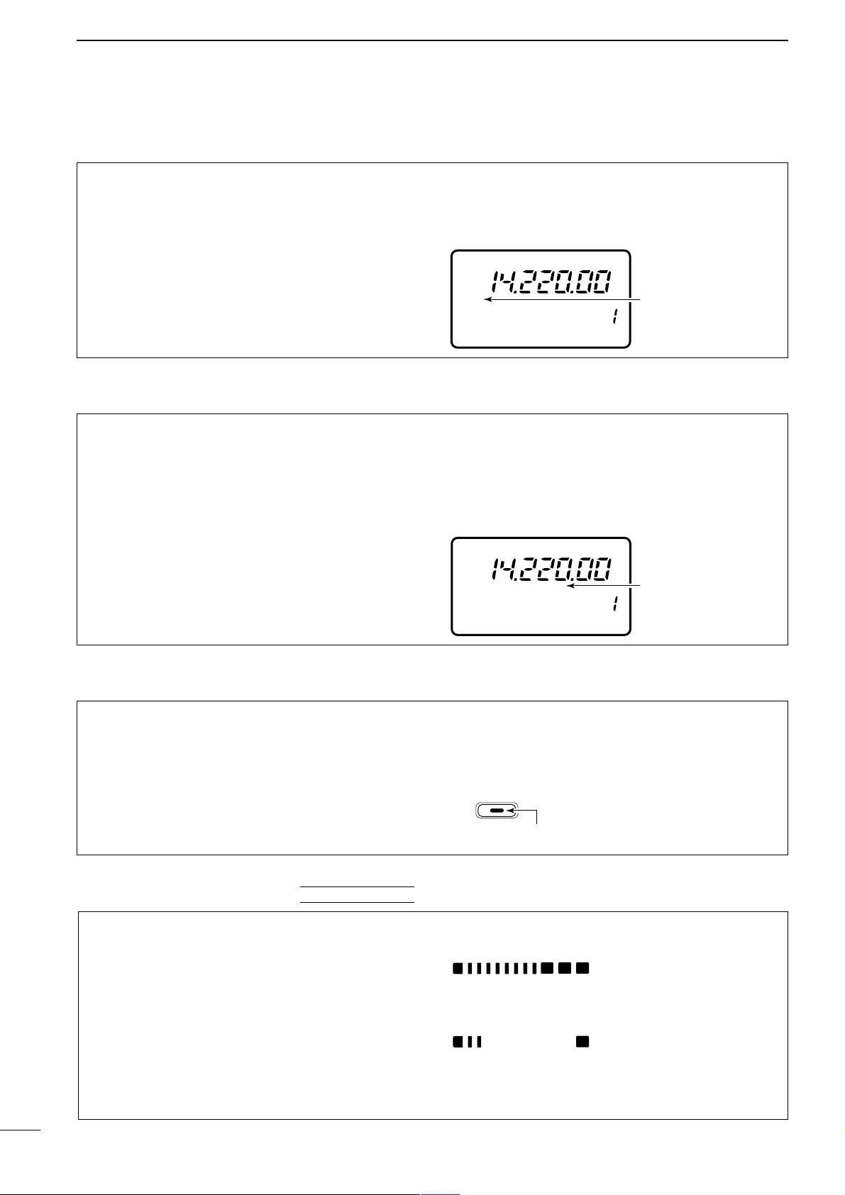
• Band selection
All HF ham bands, the 50 MHz band, the 144 MHz
band and a general coverage receiver band are
included in the IC-706MKIIG.
Push [
(Y)BAND]/[(Z)BAND] to select the desired
band.
• Pushing [(Y)BAND]/[(Z)BAND] continuously scrolls
through the available bands.
Note: The band stacking register can also be used to
select bands. Refer to p. 19.
USB
FM
USB
USB
LSB
Z
Z
■ Frequency setting
Programmable tuning
step indicator
10 kHz tuning step is
selected for USB
operation.
CH
VFO A
PO
S1
5
537920401060dB
USB
USB
M1 A/B A=B
DIAL
SPL
Rotate
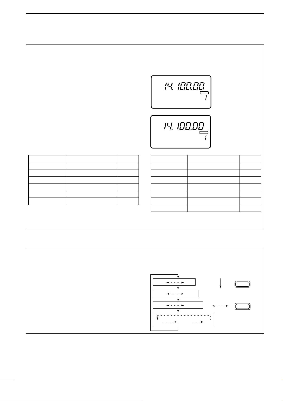
• 1 Hz and 10 Hz tuning steps
When neither the quick tuning step or programmable
tuning step, “Z,” appear, rotating the main dial
changes the frequency in increments of 1 or 10 Hz.
These tuning steps are only available in SSB, CW
and RTTY modes.
➀ Select SSB, CW or RTTY mode if necessary.
➁ Push [TS] for 2 sec. to toggle between the 1 and
10 Hz step settings.
• When the 1 Hz step is selected, the 1 Hz digit appears
in the frequency indication; when the 10 Hz step is
selected, the 1 Hz digit disappears from the frequency
indication.
Rotating the main dial
changes the frequency
in 10 Hz steps.
Rotating the main dial
changes the frequency
in 1 Hz steps.
TS
Push
for 2 sec.
VFO A
USB
VFO A
USB
Page 21
18
3
FREQUENCY SETTING
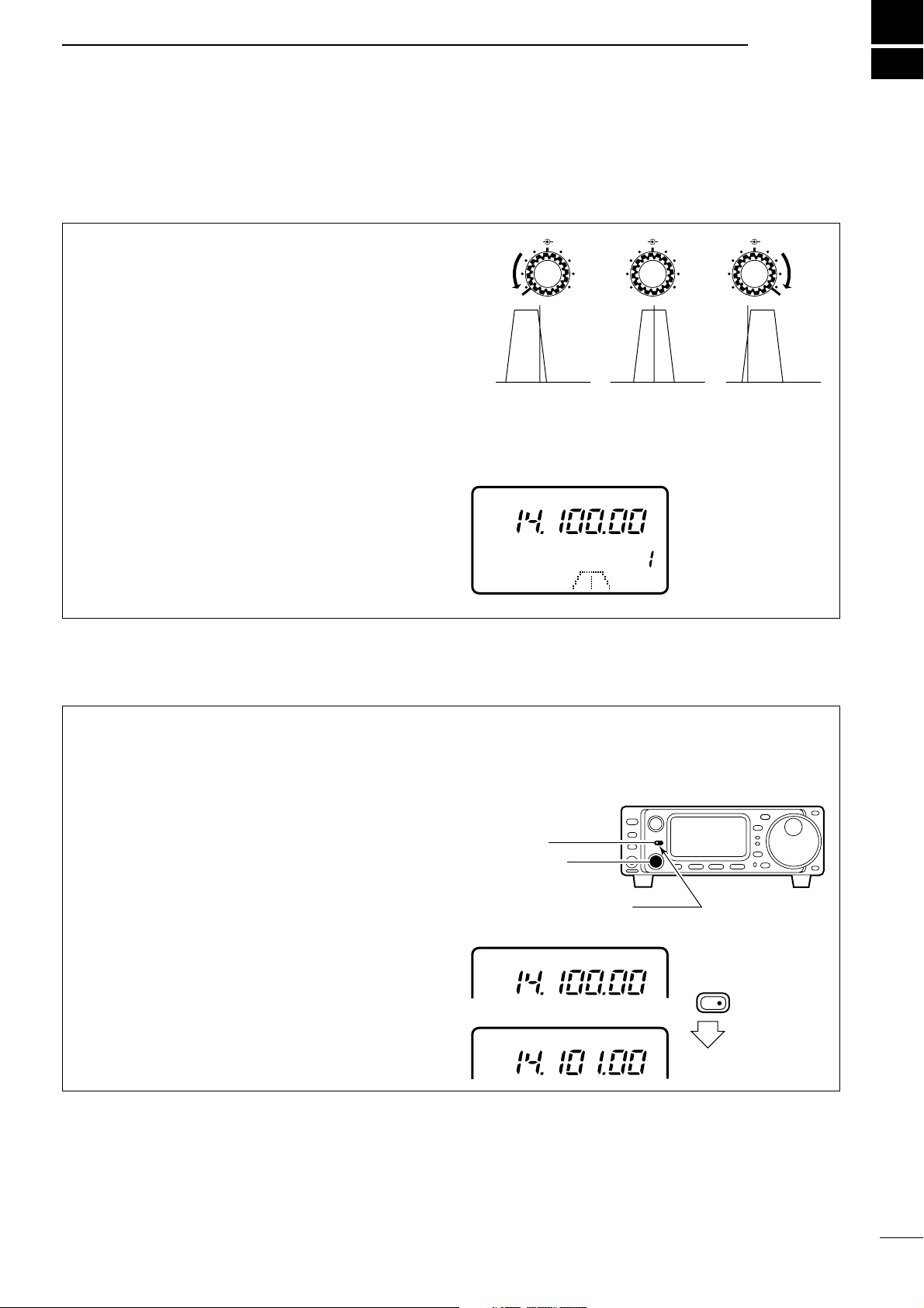
• 1 MHz quick tuning step
The quick tuning step function allows you to change
the frequency in 1 MHz steps when rotating the main
dial. This function is only available in FM, WFM and
AM modes.
➀ Select FM, WFM or AM mode if necessary.
➁ Push [TS] momentarily to toggle between the 1
MHz tuning step and the programmable tuning
step.
•“Z” appears above the 1 MHz indicator when the 1
MHz tuning step is selected.
• When the 1 MHz tuning step is selected, slow rotation
of the main dial changes the frequency in 1 MHz steps
and fast rotation of the main dial changes the frequency in 5 MHz steps.
Quick tuning step
indicator
Rotating the main dial
changes the frequency in 1 MHz steps.
FM
FM
[TS] SWITCH FLOW CHART
SSB/CW/RTTY modes Any mode FM/WFM/AM modes
TS
USB
10 Hz tuning
USB
1 Hz tuning
momentarily momentarily
momentarily
2 sec.2 sec.
2 sec.
TS
TS
1 MHz tuning
USB
Programmable step tuning
(100 Hz –100 kHz)
Selectable for each mode.
USB
Rotate DIAL
FM
• Sub dial function
The sub dial function allows you to change the operating frequency using the [M-CH] control. This gives
you more control in tuning since the [M-CH] knob is
detented—each click changes the frequency according to the set tuning step. This function is always
available in FM, WFM and AM modes. However, in
SSB, CW and RTTY modes, the set mode item “Sub
dial function,” must be set to “FrEq.”
➀ Push [RIT/SUB] to turn the sub dial function ON.
• The [SUB] indicator lights green; if it lights red, the RIT
function is activated—sub dial function must be set in
initial set mode in this case.
➁ Rotate [M-CH] to change the operating frequency
according to the set tuning steps.
➂ Push [RIT/SUB] again to turn the function OFF.
• The [SUB] indicator turns off.
[SUB] switch
Indicator lights green
while the sub dial function
is activated.
[M-CH] control
RIT/
SUB
Page 22
19
3
FREQUENCY SETTING
• Quick band change function
The quick band change function automatically stores
the last frequency and mode used for each band in a
band stacking register. This is convenient for contest
operation, etc. The tables below show the quick band
change default settings for each band.
➀ Select S3.
• Push [DISPLAY] when M or G is displayed.
• Push [MENU] twice to select
S3.
➁ Push [F-1]–[F-3] to select a band stacking register.
• The default settings for [F-1]–[F-3] are 7, 144 and 430
MHz bands, respectively.
➂ To change the settings for [F-1]–[F-3] from their
defaults, push [F-1]–[F-3] for 1 sec. one or more
times to until the desired band appears in the display above the corresponding switch.
• The last-used frequency and mode for the selected
band are displayed.
*General refers to the general coverage receiver (
GEN in
the display) and the range varies according to version.
** 1.83000 MHz
for Italy version (#10,#20).
■ Mode selection
The following modes are available in the IC706MKIIG:
SSB (LSB/USB), CW, CW-å (CW reverse), FM,
WFM (receive only), AM, RTTY and åRTTY (RTTY
reverse).
To select the desired mode of operation push
[MODE] one or more times, then push [MODE] for 2
sec., if necessary. See the diagram at right for the
order of selection.
• The selected mode is indicated in the function display.
Note: If a desired mode cannot be selected, it may be
hidden using Initial Set mode (p. 50).
OPERATING MODE SELECTION
MODE
Push
momentarily
MODE
Push
for 2 sec.
USB LSB
CW CWå
RTTY åRTTY
FM WFM AM
BAND FREQUENCY MODE
18 MHz 18.15000 MHz USB
21 MHz 21.30000 MHz USB
24 MHz 24.95000 MHz USB
28 MHz 28.60000 MHz USB
50 MHz 50.10000 MHz USB
144 MHz 145.00000 MHz FM
BAND FREQUENCY MODE
1.9 MHz
1.91000 MHz**
CW
3.5 MHz 3.56000 MHz LSB
7 MHz 7.06000 MHz LSB
10 MHz 10.13000 MHz CW
14 MHz 14.10000 MHz USB
General* 15.10000 MHz USB
BLANK
CH
VFO A
S1
5379204060dB
USB
S3
7
144
430
Display shows the
default bands for the
quick band change
function.
PO 5
10
BLANK
CH
VFO A
S1
5379204060dB
USB
S3
7
GEN
144
Display shows [F-2]
has been changed from
its default of the 50 MHz
band to the general
receiver band.
PO 5
10
430 MHz 433.00000 MHz FM
Page 23
20
4
RECEIVE AND TRANSMIT
The IF shift function electronically changes the passband frequency of the IF (intermediate frequency)
and cuts out higher or lower frequency components
of the IF to reject interference. The function shifts the
IF frequency up to ±1.2 kHz in 15 Hz steps in
SSB/CW/RTTY modes and up to ±250 Hz in 3 Hz
steps in CW-ã/RTTY-ã modes. The IF shift is not
available in FM and AM modes.
➀ Adjust the [SHIFT] control for a minimum interfer-
ence signal level.
• The audio tone may be changed while the IF shift is in
use.
➁ Set the shift control to its center position when
there is no interference.
• Graphic display
The IF shift is displayed graphically (for about 1 sec.)
each time the shift control is rotated.
M-CH M-CH M-CHSHIFT SHIFT SHIFT
Shifts low Center Shifts high
D RIT function
The RIT (Receive Incremental Tuning) function compensates for off-frequencies of communicating stations. The function shifts the receive frequency up to
±9.99 kHz in 10 Hz steps without moving the transmit
frequency. The [SUB/RIT] switch in Initial Set Mode
must be set to RIT mode in advance (p. 51).
➀ Push [RIT].
• The [RIT] indicator lights red.
➁ Rotate the [M-CH] control to cancel the off-fre-
quencies.
• The transmit frequency is not shifted.
➂ To cancel the RIT function, push [RIT] again.
• The [RIT] switch indicator goes out.
• Calculate function
The shift frequency of the RIT function can be
added/subtracted to the displayed frequency.
While the RIT indicator is lit, push and hold [RIT] for
2 sec.
Note: The RIT function is not available in FM, WFM
or AM modes regardless of the Initial Set mode setting (p. 51).
[RIT] switch
Indicator lights red while
RIT function is activated.
Push for
2 sec.
[M-CH] control
USB
USB
CH
VFO A
S1
5379204060dB
USB
D IF shift function
■ Functions for receive
Page 24
21
4
RECEIVE AND TRANSMIT
D Noise blanker
The noise blanker reduces pulse-type noise such as
that generated by automobile ignition systems. This
function is not effective for FM modes or for non pulsetype noise. If you don’t want to use the noise blanker
for AM communications, the “AM noise blanker” item
in Initial Set mode must be turned OFF (ON is the
default setting—p. 53).
➀ Select M3.
• Push [DISPLAY] 1 or 2 times when S or G is displayed.
• Push [MENU] one or more times to select
M3.
➁ Push [(F-2)NB] to toggle the noise blanker ON and
OFF.
•“NB” appears when the noise blanker is turned ON.
NB
CH
VFO A
S1
5379204060dB
USB
M3
NAR
NB
MET
Appears when the
noise blanker is
turned ON.
PO 5
10
D AGC time constant
The AGC (Automatic Gain Control) controls receiver
gain to produce a constant audio output level even
when the received signal strength is varied by fading,
etc. Use AGC slow for normal phone operation; AGC
fast for receiving data and searching for signals.
AGC time constant cannot be changed in FM mode.
➀ Select M4.
• Push [DISPLAY] 1 or 2 times when S or G is displayed.
• Push [MENU] one or more times to select
M4.
➁ Push [(F-3)AGC] to toggle the AGC time constant
between fast and slow.
•“FAGC” appears when the fast time constant is selected.
CH
VFO A
S1
5379204060dB
USB
M4
VOX
COM
AGC
Appears when
AGC fast is
selected.
FAGC
PO 5
10
D Preamp and attenuator
The preamp amplifies received signals in the front
end circuit to improve the S/N ratio and sensitivity.
Turn this function ON when receiving weak signals.
The
attenuator prevents desired signals from distort-
ing when very strong signals are near the desired frequency or when very strong electric fields, such as
from broadcasting stations, are near your location.
Push [P.AMP/ATT] momentarily to turn the preamp
ON and OFF; push and hold to turn the attenuator ON.
• Lights green when the preamp is ON; lights red when
the 20 dB attenuator is ON.
• Only one of these functions can be activated at a time.
P.AMP/ATT
Lights green while the preamp is activated;
lights red while the attenuator is activated.
D Peak meter hold
The peak meter hold function freezes the highest displayed bar segment in any meter function for about
0.5 sec. so that you can more easily read the meter.
This function can be turned ON and OFF in initial set
mode (see p. 51).
INITIAL SET MODE
S1
5379204060dB
S1
5379204060dB
Initial reception of a
signal results in an Smeter reading of 40
dB.
The highest indicated
bar remains displayed
for about 0.5 sec.
even when the signal
strength decreases.
[EXAMPLE]:
Page 25

22
4
RECEIVE AND TRANSMIT
D RF gain and squelch
D Simple band scope
The IC-706MKIIG uses the same control, [RF/SQL],
to adjust one of either the RF gain or the squelch.
[RF/SQL] adjusts either the RF gain or the squelch
depending on the operating mode selected and the
condition of the RF gain item in initial set mode (p.
51; also see the table at right).
The
RF (Radio Frequency) gain is used to adjust the
receiver gain.
• This control should be set to the 11 o’clock position for
normal use.
• Shallow rotation moves the S-meter to the right indicating
the signal strength which can be received.
The SQUELCH removes noise output from the
speaker (closed condition) when no signal is
received. The squelch is particularly effective for FM.
It is also available for the other modes.
• When operating in FM, first rotate the control fully counterclockwise. Then, rotate the control clockwise to the
point where the noise just disappears. This is the best
position. The squelch does not open for weak signals
when it is set too deep.
• A segment appears in the S-meter to indicate the S-meter
squelch level.
• [RF/SQL] control priority
AF RF/SQL
Max. RF gain position
RF gain
decreases
Same effect as at
the center position
AF RF/SQL
Deep
Squelch
opens
S-meter squelch
threshold point
Noise squelch
threshold point
This function allows you to visually “sweep” an area
surrounding the set frequency for other signals.
Detected signals are indicated graphically in the dot
matrix section of the display.
➀ Set a mode and frequency.
➁ Select G1.
• Push [DISPLAY] 1 or 2 times if M or S appears.
• Push [MENU] one or more times to select
G1.
➂ Push [F-1] one or more times to select the desired
steps.
• Each dot corresponds to a step for the indicated frequency.
• 0.5, 1, 2, 5, 10, 20 and 100 kHz can be set for the scope
step.
➃ Push [F-3] to start the sweep.
•“___” (below SWP) flashes while sweeping.
• The receive audio is muted while sweeping.
➄ Rotate the main dial if you want to monitor the dis-
played signals.
• The sweep marker indicates the location of the dis-
played frequency in the sweep readout.
• If the displayed frequency is outside of the sweep read-
out (determined by the sweep width), the sweep marker flashes.
➅ Push [F-2] to return the frequency to the start of a
sweep.
• The sweep marker moves back to the center position.
1k
SWP
2k
SWP
2k
SWP
2k
SWP
___
2k
SWP
Select sweep width
([F-1])
Start sweep
([F-3])
Sweep is finished
([F-3] again)
Move sweep marker
(main dial)
2k
SWP
Returns to previous
frequency ([F-2])
sweep marker
Note: The recommended
position for RF gain is the
11 o ’clock position since
this sets RF gain to the
max.
When set to AUTO, SQL is
active in FM/WFM/AM; RF
is active in SSB/CW/RTTY.
Note: Use the attenuator or turn OFF the preamp when
using the band scope on a band containing a lot of noise.
Initial set mode
setting
USB, LSB,
CW, RTTY
AM, FM, WFM
SQL*
1
SQL SQL
AUTO RF GAIN SQL
RF • SQL*
2
RF/SQL RF/SQL
*1Default; *2Default for USA version.
Page 26
Filter variations
*Optional filter.
Optional filter installation and selection tables
SSB
23
4
RECEIVE AND TRANSMIT
D Optional filter selection
Two optional filters can be installed in the IC706MKIIG.
Narrow filters help reject interference from adjacent
signals and obtain good selectivity.
Wide filters provide improved audio for SSB operation when no interfering signals are present.
Consult the table below to select a filter most suitable
for your operating needs.
Narrow filters for AM/FM modes are standard.
FILTER PRESETTING:
After you install a filter (see p. 60 for installation), you
must specify the installed filter in initial set mode
(item 19 “OPT. FIL 1” or item 20 “OPT. FIL 2”; see
p. 51).
FILTER ON/OFF:
➀ Select M3.
• Push [DISPLAY] 1 or 2 times if G or S appears.
• Push [MENU] one or more times to select
M3.
➁ Push [(F-1)FIL] momentarily to select the narrow
filter; for 2 sec. to select the wide filter.
• ã appears when the narrow filter is selected; ç
appears when the wide filter is selected.
Note: When selecting the narrow filter, the graphic
passband is narrowed (see diagram below).
Normal
operation
narrow is
selected
FL-101* CW, RTTY 250 Hz/–6 dB
CW, RTTY 350 Hz/–6 dB
CW, RTTY 500 Hz/–6 dB
SSB, CW, RTTY 2.8 kHz/–6 dB
FL-223* SSB, CW, RTTY 1.9 kHz/–6 dB
SSB, CW, RTTY 2.4 kHz/–6 dB
AM, FM 8 kHz/–6 dB
Mode Band widthName
FIL 1
FIL 2
No
optional
filter
FL-100 FL-101 FL-103 FL-223 FL-232
No
optional
filter
W: –––
M: FL-272
N: –––
W: –––
M: FL-272
N: –––
W: –––
M: FL-272
N: –––
W:FL-103
M: FL-272
N: –––
W:–––
M: FL-272
N: FL-223
W: –––
M: FL-272
N: –––
FL-100
W: –––
M: FL-272
N: –––
W: –––
M: FL-272
N: –––
W: –––
M: FL-272
N: –––
W:FL-103
M: FL-272
N: –––
W:–––
M: FL-272
N: FL-223
W: –––
M: FL-272
N: –––
FL-101
W: –––
M: FL-272
N: –––
W: –––
M: FL-272
N: –––
W: –––
M: FL-272
N: –––
W:FL-103
M: FL-272
N: –––
W:–––
M: FL-272
N: FL-223
W: –––
M: FL-272
N: –––
FL-103
W: FL-103
M: FL-272
N: –––
W: FL-103
M: FL-272
N: –––
W: FL-103
M: FL-272
N: –––
W: FL-103
M: FL-272
N: –––
W: FL-103
M: FL-272
N: FL-223
W: FL-103
M: FL-272
N: –––
FL-223
W: –––
M: FL-272
N: FL-223
W: –––
M: FL-272
N: FL-223
W: –––
M: FL-272
N: FL-223
W:FL-103
M: FL-272
N: FL-223
W:–––
M: FL-272
N: FL-223
W: –––
M: FL-272
N: FL-223
FL-232
W: –––
M: FL-272
N: –––
W: –––
M: FL-272
N: –––
W: –––
M: FL-272
N: –––
W: FL-103
M: FL-272
N: –––
W: –––
M: FL-272
N: FL-223
W: –––
M: FL-272
N: –––
FIL 1
FIL 2
No
optional
filter
FL-100 FL-101 FL-103 FL-223 FL-232
No
optional
filter
W: –––
M: FL-272
N: –––
W: –––
M: FL-272
N: FL-100
W: –––
M: FL-272
N: FL-101
W:FL-103
M: FL-272
N: –––
W:–––
M: FL-272
N: FL-223
W: –––
M: FL-272
N: FL-232
FL-100
W: –––
M: FL-272
N: FL-100
W: –––
M: FL-272
N: FL-100
W: FL-272
M: FL-100
N: FL-101
W:FL-103
M: FL-272
N: FL-100
W:FL-272
M: FL-223
N: FL-100
W:FL-272
M: FL-100
N: FL-232
FL-101
W: –––
M: FL-272
N: FL-101
W: FL-272
M: FL-100
N: FL-101
W: –––
M: FL-272
N: FL-101
W:FL-103
M: FL-272
N: FL-101
W: FL-272
M: FL-223
N: FL-101
W:FL-272
M: FL-232
N: FL-101
FL-103
W: FL-103
M: FL-272
N: –––
W: FL-103
M: FL-272
N: FL-100
W: FL-103
M: FL-272
N: FL-101
W: FL-103
M: FL-272
N: –––
W: FL-103
M: FL-272
N: FL-223
W: FL-103
M: FL-272
N: FL-223
FL-223
W: –––
M: FL-272
N: FL-223
W:FL-272
M: FL-223
N: FL-100
W:FL-272
M: FL-223
N: FL-101
W:FL-103
M: FL-272
N: FL-223
W:–––
M: FL-272
N: FL-223
W:FL-272
M: FL-223
N: FL-232
FL-232
W: –––
M: FL-272
N: FL-232
W: FL-272
M: FL-100
N: FL-232
W: FL-272
M: FL-232
N: FL-101
W: FL-103
M: FL-272
N: FL-232
W: FL-272
M: FL-223
N: FL-232
W: –––
M: FL-272
N: FL-232
FL-100*
FL-232*
FL-94
FL-103*
FL-272
FM
Normal FL-23 + SFPC455E
Narrow FL-94
AM
Normal FL-94
Narrow FL-272
CW, RTTY
Table key:
W—wide position
M—medium (normal) position
N—Narrow position
Page 27

24
4
RECEIVE AND TRANSMIT
This function automatically attenuates beat tones,
tuning signals, etc., even if they are moving. The
automatic notch filter functions in SSB, FM and AM
modes.
➀ Select S4 (DSP menu).
• Push [DISPLAY] 1 or 2 times when M or G is displayed.
• Push [MENU] one or more times to select
S4.
➁ Push [(F-1)ANF] to toggle the automatic notch filter
ON and OFF.
•“DSP” and “ANF” appear when the function is ON.
D NR (Noise Reduction) function
This function reduces noise components and picks
out desired signals which are buried in noise. The
received AF signals are converted to digital signals
and then the desired signals are separated from the
noise. The noise reduction function is available for all
operating modes.
➀ Select S4 (DSP menu).
• Push [DISPLAY] 1 or 2 times when M or G is displayed.
• Push [MENU] one or more times to select
S4.
➁ Push [(F-2)NR] to toggle the noise reduction func-
tion ON and OFF.
•“DSP” and “NR” appear when the function is ON.
➂ Push [(F-3)NRL] to toggle the noise reduction level
indication ON and OFF.
➃ Rotate the [M-CH] control to set the noise reduc-
tion level.
• Set the control for maximum readability. Deep rotation
results in audio signal masking or distortion.
☞ NOTE:Pushing [(F-3)NRL] automatically turns the
noise reduction function ON, however, the transceiver maintains the ON/OFF condition when
pushing [(F-2)NR].
D ANF (Automatic Notch Filter) function
■ DSP Functions (may require an optional unit depending on version—see p. 61)
DSP
CH
VFO A
P
O
S1
5
5379204060dB
USB
BLANK
ANF
S4
ANF
NR
NRL
DSP
CH
VFO A
P
O
S1
5
5379204060dB
USB
BLANK
NR
S4
ANF
NR
NRL
S4
LEVEL 8
NRL
Page 28

25
4
RECEIVE AND TRANSMIT
• Setting output power
➀
Push [DISPLAY] for 2 sec. to select quick set mode.
➁ Push [MENU] one or more times to select Q1 RF
POWER.
➂ Rotate the main dial to select the desired output.
• Output power is displayed in 11 steps (L, 1–9 and H)
but is continuously selectable.
➃ Push [DISPLAY] to exit quick set mode.
• Available power
*Carrier power
• Setting microphone gain
Microphone gain must be adjusted properly so that
your signal does not distort when transmitted.
➀ Select SSB or another phone mode.
➁
Push [DISPLAY] for 2 sec. to select quick set mode.
➂ Push [MENU] one or more times to select Q2 MIC
GAIN.
• The ALC meter is selected automatically when operating in SSB mode.
➃ While speaking into the microphone adjust the mic
gain so that the ALC meter does not peak past the
ALC zone.
➄ Push [DISPLAY] to exit quick set mode.
USB
Q1 RF POWER
Maximum output power is
selected.
PO
S1
5
537920401060dB
Microphone gain is
set to 6.
ALC
S1
123
5379204060dB
USB
Q2
MIC GAIN
ALC
ALC zone
D Meter function
The bar meter in the function display acts as an
S-meter (for relative signal strength, except in WFM
mode) during receive and can be selected for one of
three types during transmit.
➀ Select M3.
• Push [DISPLAY] 1 or 2 times when S or G appears.
• Push [MENU] one or more times to select
M3.
➁ Push [(F-3)MET] one or more times to select the
desired meter function.
• The display indication changes as in the table at right.
D Output power and mic gain
■ Functions for transmit
Note: The SWR meter cannot be used for the 144/430
MHz bands since the meter activates for the [ANT 1] connector only.
BAND SSB/CW/RTTY/FM AM*
HF 5–100 W 4–40 W
50 MHz 5–100 W 4–40 W
144 MHz 2–20 W 2–8 W
DISPLAY
INDICATION
MEASUREMENT
Po
Indicates the relative RF output power.
ALC
Indicates the ALC level. When the
meter movement shows the input signal
level exceeds the allowable level, the
ALC limits the RF power. In such cases,
reduce the microphone gain (see
above).
SWR
Indicates the SWR over the transmission line.
Page 29
26
4
RECEIVE AND TRANSMIT
D Speech compressor
The IC-706MKIIG has a built-in, low distortion
speech compressor circuit. This circuit increases
your average talk power in SSB mode and is especially useful for DX’ing when the receiving station is
having difficulty copying your signal.
➀ Select USB or LSB mode.
➁ Select the ALC meter.
• Push [DISPLAY] 1 or 2 times to select M, if necessary.
• Push [MENU] one or more times to select
M3, then
push [
(F-3)MET] one or more times to select “ALC.”
➂ Select the mic gain display in quick set mode.
• Push [DISPLAY] for 2 sec.
• Push [MENU] one or more times to select
Q2 MIC
GAIN
.
➃ Adjust the mic gain.
• While transmitting at your normal voice level, the ALC
meter should read at about the middle of the ALC zone.
• Be sure the mic gain is in the range of 2 to 5.
➄ Select M4.
• Push [DISPLAY] 1 or 2 times to select M, if necessary.
• Push [MENU] one or more times to select
M4.
➅ Push [(F-2)COM], then adjust [COMP GAIN] so that
the ALC meter reads within the ALC zone whether
you speak softly or loudly.
Note: When the ALC meter peaks above the ALC
zone, your transmitted voice may be distorted.
[MENU] [(F-2)COM]
[COMP GAIN]
COMP
GAIN /SIDE T
BEEP
ALC
Adjust [COMP GAIN] so that the ALC meter
reads within the ALC zone.
ALC zone
D VOX operation
The VOX (Voice-operated Transmission) function
toggles between transmit and receive with your
voice. This function provides an opportunity to input
log entries into your computer, etc., while operating.
➀ Select M4, then turn the VOX function ON.
• Push [DISPLAY] 1 or 2 times when S or G appears.
• Push [MENU] one or more times to select
M4.
• Push [
(F-1)VOX] to turn the function ON.
➁ Select VOX GAIN in quick set mode.
• Push [DISPLAY] for 2 sec. then push [MENU] one or
more times to select
Q4.
➂ While speaking into the microphone, adjust [VOX
GAIN] until the transceiver is transmitting.
➃ Select VOX DELAY in quick set mode.
• Push [MENU] one or more times to select Q3.
➄ While speaking into the microphone, adjust [VOX
DELAY] as desired.
➅ Select ANTI VOX in quick set mode.
• Push [MENU] one or more times to select Q5.
➆ If the receive audio from the speaker toggles the
transceiver to transmit during receive, adjust the
[ANTI-VOX] to the point where it has no effect.
➇ Push [DISPLAY] to exit quick set mode.
[MENU] [(F-1)VOX]
[DISPLAY]
main dial
Page 30

27
4
RECEIVE AND TRANSMIT
The AT-180 automatic antenna tuner matches the IC706MKIIG to the connected antenna automatically.
Once the tuner matches an antenna, the variable
capacitor angles are memorized as a preset point for
each frequency range (100 kHz steps). Therefore,
when you change the frequency range, the variable
capacitors are automatically preset to the memorized
point.
Note:
• The AT-180 cannot be used for the 144/430 MHz
band.
• When operating on the 144/430 MHz band, pushing
the tuner switch selects the call channel (p. 39).
• The AT-180 can match both HF and 50 MHz bands.
However, operation is different for the HF and 50
MHz bands.
TUNER OPERATION
• For the HF band:
Push [TUNER] to turn the tuner ON. The antenna is
tuned automatically during transmission when the
antenna SWR is higher than 1.5:1.
• When the tuner is OFF, the [TUNER] light goes out.
• For the 50 MHz band:
Push and hold [TUNER] to tune the antenna. If the
[TUNER] light flashes slowly while transmitting, push
and hold [TUNER] again to re-tune the antenna.
MANUAL TUNING
During SSB operation on HF bands at low voice levels, the AT-180 may not be tuned correctly. In such
cases, manual tuning is helpful.
Push and hold [TUNER] for 1 sec. to start manual
tuning.
• CW mode is selected, a side tone is emitted, and the
[TUNER] light flashes; then, the previous mode is selected.
If the tuner cannot reduce the SWR to less than 1.5:1
after 20 sec. of tuning, the [TUNER] light goes out. In
this case, check the following:
• the antenna connection and feedline
• the antenna SWR (p. 26; meter function)
Through inhibit (HF bands only)
The AT-180 has a through inhibit condition. When
selecting this condition, the tuner can be used at poor
SWR’s. In this case, automatic tuning in the HF
bands activates only when exceeding SWR 3:1.
Therefore, manual tuning is necessary each time you
change the frequency. Although termed “through
inhibit,” the tuner will be “through” if the SWR is higher than 3:1 after tuning.
• Tuner sensitive condition (HF bands only)
If you require critical tuning at any time during transmission, select the tuner sensitive condition. See
p. 55 for selection.
• Automatic tuner start (HF bands only)
If you want to turn OFF the tuner under conditions of
VSWR 1.5:1 or less, use “automatic tuner on” and
turn the tuner OFF. See p. 54 for turning the function
ON and OFF.
D Optional AT-180
AUTOMATIC ANTENNA TUNER
operation
[TUNER/CALL]
Lights to indicate the AT-180
is turned ON.
[TUNER/CALL]
Flashes to indicate re-tuning
is necessary.
CAUTION: NEVER transmit with the tuner ON
when no antenna is connected. This will damage
both the transceiver and the antenna tuner.
[TUNER/CALL]
Push and hold for 1 sec. to start
manual tuning.
CONVENIENT
Page 31

28
4
RECEIVE AND TRANSMIT
The AH-4 matches the IC-706MKIIG to a long wire
antenna more than 7 m/23 ft long (3.5 MHz and
above).
• See p. 14 for connection.
• See the AH-4 instruction manual for AH-4 installation and
antenna connection details.
NEVER operate the AH-4 without an antenna wire.
The tuner and transceiver will be damaged.
NEVER operate the AH-4 when it is ungrounded.
Transmitting before tuning may damage the transceiver. Note that the AH-4 cannot tune when using a
1
⁄2 λ long wire or multiple of the operating frequency.
Note: The AH-4 can be used for HF bands and the
50 MHz band only.
AH-4 operation
➀ Set the desired frequency in an HF band.
• The AH-4 will not operate on frequencies outside of
ham bands.
➁ Push and hold [TUNER] for 2 sec.
• The [TUNER] light flashes and “CW” appears while tuning.
➂ The [TUNER] light lights constantly when tuning is
complete.
• When the connected wire cannot be tuned, the
[TUNER] light goes out, the AH-4 is bypassed and the
antenna wire is connected to the antenna connector on
the transceiver directly.
➃ To bypass the AH-4 manually, push [TUNER].
• PTT tune function
The AH-4 is always tuned when the PTT is pushed
after the frequency is changed (more than 1%). This
function removes the “push and hold [TUNER]” operation and activates first transmission on the new frequency. This function is turned ON in initial set mode,
item 13 (p. 54).
D Optional AH-4
AUTOMATIC ANTENNA TUNER
operation
AH-4 setting example:
For mobile operation
For outdoor operation
Long wire
Optional AH-2b
antenna element
RWARNING: HIGH VOLTAGE!
NEVER touch the antenna element while tuning or
transmitting.
Tuning is required for each frequency. Be sure to
re-tune the antenna before transmitting when you
change the frequency—even slightly.
USB
CW
Push [TUNER] for 2 sec.
CONVENIENT
Page 32

29
4
RECEIVE AND TRANSMIT
Split frequency operation allows you to transmit and
receive on two different frequencies. Split frequency
operation uses 2 frequencies, one in VFO A and the
other in VFO B.
Following is an example of setting 7.057 MHz, CW
mode in VFO A (for receive) and 7.025 MHz, CW
mode in VFO B (for transmit).
➀ Select VFO A and set the frequency to 7.057
MHz/CW.
• [(F-2)A/B] is available when M1 appears.
• [
(F-3)V/M] is available when M2 appears.
➁ Push or push and hold [(F-1)SPL] in the M1 dis-
play.
➥ Push [SPL]: activates split only.
➥ Push and hold [SPL]: activates the quick split
below.
➂ To change the receive frequency, rotate the main
dial; to change the transmit frequency, rotate the
main dial while pushing [(F-3)XFC].
• The transmit frequency can be monitored while pushing
[
(F-3)XFC].
• Split operation is now set for receive on 7.057 MHz/CW
and transmit on 7.025 MHz/CW.
To exchange the transmit and receive frequencies,
push [(F-2)A/B] in M1.
CONVENIENT
The G3 display conveniently shows the transmit frequency during split frequency operation and [(F-3)Ñ]
allows you to change the transmit frequency.
• Split lock function
The split lock function is convenient for changing only
the transmit frequency. Otherwise, accidentally
releasing the [(F-3)XFC] switch while rotating the
main dial changes the receive frequency. The split
lock’s effectiveness can be selected in initial set
mode (item 12) for both receive and transmit frequencies; or only the receive frequency. (p. 52)
D Quick split function
In M1, when you push [(F-1)SPL] for 2 sec., split frequency operation is turned ON and VFO B is automatically changed according to the plus/minus preprogrammed shift frequency set in initial set mode (or
equalized when 0 kHz is programmed as the split
shift frequency). This shortens the time needed to
start split frequency operation—great for DX’ing.
The quick split function is ON by default. If desired, it
can be turned OFF in initial set mode (p. 51). In this
case, pushing [
(F-1)SPL] for 2 sec. has the same
effect as pushing [(F-1)SPL] momentarily as in normal split operation.
PROGRAMMING SPLIT SHIFT FREQUENCY
➀ Push [POWER] to turn power OFF.
➁ While pushing [LOCK], push [POWER] to turn
power ON and enter initial set mode.
➂ Select “SPL OFFSET” using [MENU], [M-CH] or
the [Y]/[Z] keys, then rotate the main dial to select
the desired split offset.
• The split offset can be selected from –4000 kHz to
+4000 kHz.
Note: This setting is not valid for FM operation. This
is because FM operation uses the duplex setting for
repeater operation (next page).
VFO A
CW
SPL
VFO A
CW
SPL
VFO B
CW
VFO A
VFO A
SPL
SPL SPL
SPL
VFO A
VFO B
VFO B
No shift frequency is programmed.
+10 kHz is programmed as a shift
frequency.
Push for 2 sec.
SPL
F-1
■ Split frequency operation
16 SPL OFFSET
Page 33

30
4
RECEIVE AND TRANSMIT
D Repeater operation
A repeater amplifies received signals and retransmits
them at a different frequency. When using a repeater,
the transmit frequency is shifted from the receive frequency by an offset frequency. A repeater can be
accessed using split frequency operation with the
shift frequency set to the repeater’s offset frequency.
➀ Set the offset frequency and turn ON the quick split
function in initial set mode in advance (p. 52).
• If the quick split function is turned OFF, both transmit
and receive must be set separately.
➁ Push [MODE] one or more times to select FM
mode, then set the receive frequency.
➂ Select a suitable tone frequency or the 1750 Hz
tone burst in quick set mode.
➥ Push [DISPLAY] for 2 sec., then push [MENU]
one or more times to select “Q4 RPTR TONE.”
• If FM mode has not been selected, this item does
not appear.
➥ Rotate the main dial to set a subaudible tone fre-
quency or the 1750 Hz tone burst function.
➥ Push [DISPLAY] to exit quick set mode.
➃ Push [(F-1)SPL] for 2 sec. (in the M1 display) to
activate the split frequency function (duplex function) with the pre-selected offset.
• When a subaudible tone frequency (excepting 1750 Hz)
is selected in
➂, “FM-T” is selected simultaneously.
➄ Push and hold [PTT] to transmit; release [PTT] to
receive.
• When a 1750 Hz tone burst is selected, push and hold
[
(F-3)TON] in the M4 display while pushing [PTT] to
send the 1750 Hz tone burst.
➅ To check the repeater input frequency (direct sig-
nal from the other station), push and hold
[(F-3)XFC] in the M1 display.
➆ To return to simplex operation, push [(F-1)SPL].
Each memory channel can store a tone frequency
(subaudible tones or a tone burst) and an offset frequency, as well as the operating frequency. Store
repeater information into memory channels for quick
and easy access to repeaters.
PROGRAMMING DUPLEX SHIFT FREQUENCY
➀ Push [POWER] to turn power OFF.
➁ While pushing [LOCK], push [POWER] to turn
power ON and enter initial set mode.
➂ Select “DUP 144M” using [MENU] or the
[UP]/[DN] keys, then rotate the main dial to select
the desired duplex offset.
• The duplex offset can be selected from –4000 kHz to
+4000 kHz.
12
QUICK SPLIT
Turn the quick split
function ON.
(Initial set mode default
is ON.)
Q6
RPTR TONE
Set the tone frequency
(quick set mode).
See p. 49 for setting details and available frequencies.
FM T
SPL
CH
VFO A
S1
5379204060dB
FM T
M4 VOX DUP TON
PO 5
10
CONVENIENT
17 DUP 144M
Page 34

31
4
RECEIVE AND TRANSMIT
Tone squelch operation is a method of communications using selective calling. Only received signals
having a matching tone will open the squelch. Before
communicating using tone squelch, all members of
your party must agree on the tone squelch frequency
to use.
➀ Push [MODE] one or more times to select FM
mode.
➁ Push and hold [DISPLAY] to enter Quick Set mode.
➂ Push [MENU] one or more times to select item Q7
TONE SQL.
• [Y]/[Z] or [M-CH] can also be used.
➃ Rotate the main dial to select the desired subaudi-
ble tone frequency.
• Available tone frequencies are the same as for repeater
tone operation (see previous page).
➄ Select M4 and turn the tone squelch function ON.
➥ Push [(F-3)TON] to toggle tone squelch opera-
tion ON and OFF.
• When tone squelch is turned ON, “TSQL” appears in
the display.
➅ Communicate in the usual manner.
• Push [PTT] to transmit; release to receive.
By monitoring a signal that is being transmitted on a
repeater input frequency, you can determine the tone
frequency necessary to open a repeater.
➀ During tone squelch or repeater operation, push
and hold [DISPLAY] to enter Quick Set mode.
➁ Push [MENU] one or more times to select item Q8
T-SQL SCN during tone squelch operation, or
Q8 RPTR-T SCN during repeater operation.
• [Y]/[Z] or [M-CH] can also be used.
➂ Push [(F-3)SCN] to toggle tone scan operation ON
and OFF.
• While scanning tone frequencies are displayed instead
of the operating frequency.
• When a matched tone is detected, tone scan automatically stops, the matched tone is displayed and the
repeater tone (or tone squelch tone) setting is automatically adjusted accordingly.
➃ Push [DISPLAY] to return to the main menu.
■ Tone squelch operation
■ Tone scan operation
Q7
TONE SQL
Set the tone frequency
(quick set mode).
See p. 49 for setting details and available frequencies.
During tone squelch operation.
PO
S1
5
537920401060dB
FM TSQL
Q8
T-SQL
SCN
During repeater operation.
PO
S1
5
537920401060dB
FM T
Q8
RPTR-T
SCN
FM TSQL
SPL
CH
VFO A
S1
5379204060dB
M4 VOX DUP TON
PO 5
10
Page 35

32
4
RECEIVE AND TRANSMIT
This function allows you to set repeater operation
with the push of one switch.
➀ Push [(Y)BAND]/[(Z)BAND] to select the 28 MHz
band.
➁ Rotate [DIAL] to select the operating frequency.
➂ Push [MODE] one or more times to select FM.
➃ Select M4 and turn the one-touch repeater function
ON.
➥ Push and hold [(F-2)DUP] to toggle the one-
touch repeater function ON and OFF.
• When the one-touch repeater function is turned ON,
“DUP” (duplex indicator) and “T” (tone frequency
indicator) appear in the display.
• Be sure to set the duplex direction and offset in initial set mode in advance (p. 52).
• Push [
(F-2)DUP] to toggle the duplex direction.
☞ NOTE:When you want to transmit a 1750 Hz tone,
while pushing [PTT], push [(F-3)TON] in the M4
display during repeater operation.
■ One-touch repeater function
This function automatically activates the repeater settings (DUP+ or DUP– and tone encoder ON/OFF)
when the operating frequency falls within the general
output frequency range and deactivates them when
outside of the range.
Set the auto repeater function ON or OFF in initial set
mode in advance (p. 53). When set ON, repeater settings are automatically activated according to the
table at right.
☞ NOTE:This function is available for the USA ver-
sion only.
■ Auto repeater function
FREQUENCY DUPLEX DIRECTION
145.200–145.495 MHz
“DUP–” appears
146.610–146.995 MHz
147.000–147.395 MHz “DUP+” appears
442.000–444.995 MHz “DUP+” appears
447.000–449.995 MHz “DUP–” appears
CH
VFO A
P
O
S1
5
537920401060dB
FM
BLANK
M1
SPL
A/B
A=B
CH
VFO A
DUP
P
O
S1
5
537920401060dB
FM T
BLANK
M4
VOX
DUP
TON
Page 36

33
4
RECEIVE AND TRANSMIT
D Connections for CW
D CW operation
➀ Connect a paddle or straight key as above.
➁ Select CW (or CWå) mode with [MODE].
➂ Set CW break-in operation as semi break-in, full
break-in or OFF.
•
Push [DISPLAY] one or two times to select M, if necessary.
• Push [MENU] one or more times to select M4.
• Push [
(F-2)BRK] one or more times to select the desired
condition:
➧ “F-BK”: full break-in
➧ “BK”: semi break-in
➧ No indicator: no break-in (ACC socket connection is
necessary as above.)
➃ Set the CW delay time when semi break-in opera-
tion is selected.
➥ Push [DISPLAY] for 2 sec. to select quick set
mode; push [MENU] one or more times to select
Q3 BK-IN DELAY; then rotate the main dial
to set the desired delay time (see p. 48 for
details).
CW
Q4 CW PADDLE
CW
CW
CW
CW
Paddle
[ELEC KEY]
[MICROPHONE]
See p. 34 for
connection details:
Paddle operation from
front panel MIC connector
.
Straight key
Microphone
Quick set mode settingRear panel
4
8
12
144/430 MHz
HF/50 MHz
[ACC]
123
765
9
10 11
13
For no break-in operation:
Connect an external switch such
as a foot switch; or use the
RTTY SEND terminal for all
bands. (See p. 35.)
■ Functions for CW
BK
VFO A
CW
CW
Q3
BK-IN
DELAY
M4
BRK1/4
AGC
CW mode and semi
break-in operation is
selected.
Delay time of 6.0 dots is
selected in quick set
mode for semi break-in
operation.
CH
PO
S1
5
537920401060dB
Page 37

34
4
RECEIVE AND TRANSMIT
D CW pitch control
The received CW audio pitch and monitored CW
audio pitch can be adjusted to suit your preferences
(300 to 900 Hz) without changing the operating frequency.
➀ Push [MODE] one or more times to select CW
mode.
➁ Select CW PITCH in quick set mode.
• Push [DISP] for 2 sec. then push [MENU] one or more
times.
➂ Rotate the main dial to set the desired pitch.
➃ Push [DISPLAY] to exit quick set mode.
Q2
CW
PITCH
This shows the default
setting for the CW pitch
control (600 Hz).
CW
QUICK SET MODE
D CW reverse mode
The CWå (CW Reverse) mode receives CW signals
with a reverse side CW carrier point like that of LSB
and USB modes. Use this mode when interference
signals are near the desired signal and you want to
change the interference tone.
➀ Push [MODE] one or more times to select CW
mode.
➁ Push and hold to toggle between CW and CWå
modes.
• Check the interference tone.
• Receive audio tone response
(Reverse) CWå
MODE
(Normal) CW
BFO
600 Hz
signal
inteference signal
600 Hz
BFO
inteference
D Electronic CW keyer
The IC-706MKIIG has an electronic keyer. Both keying speed and weight (the ratio of dot : space : dash)
can be set in quick set mode.
• Setting the electronic keyer
➀ Select CW mode with [MODE].
➁ Push [DISPLAY] for 2 sec. to enter quick set mode.
➂ Push [MENU] one or more times to select item Q4
CW PADDLE, then rotate the main dial to select
the paddle type.
• When “ud” is selected, the up/down switches on the
microphone can be used as a paddle.
➃ Push [MENU] two more times to select item Q6
RATIO, then rotate the main dial to select the
desired weight.
• Key weight can be selected from 2.8 to 4.5.
• Check the selected ratio with the side tone function in
CW mode.
➄
Push [DISPLAY] momentarily to exit quick set mode.
Paddle operation from front panel MIC connector
Connect a CW paddle as at right to operate an electronic keyer from the front panel MIC connector.
• This function is available from the front panel mic
connector only.
• Be sure to select item “n,” “r,” “buG” or “oFF” in Q4
CW PADDLE in quick set mode. (p. 49)
• Connect straight key to “DOT” side.
KEYING WEIGHT EXAMPLE: morse code “K”
*SPACE and DOT length can be adjusted with “Q5 KEY
SPEED” only.
DASH
Weight setting:
1:1:3 (default)
Weight setting:
Adjusted
DASH
DOT
(Fixed*)
Adjustable range SPACE (Fixed*)
QUICK SET MODE
front panel
MIC connector
MIC U/D
CW
paddle
DOT
E
DASH
➁
➆
3.9 kΩ ±5%
2.2 kΩ ±5%
Page 38

35
4
RECEIVE AND TRANSMIT
D Connections for RTTY (FSK)
D Connections for AFSK
Rear panel
TU or TNC
Personal computer
Rear panel
view
Colors refer to connection
to the supplied ACC cable.
Use either the ACC or one of the two
1
/8˝ plugs
*
1
Connect SQL line when required.
SQL*1 (light green)
AF out (light blue)
MSEND*
2
GND (red)
FSKK (black)
GND
GND
AF
3-conductor
1
/8˝ plug (supplied)
2-conductor
1
/8˝ plug
FSKK
SEND
[RTTY]
[ACC]
[EXT SP]
12334
567
7
8
9101112
13
HF/50 MHz: orange
144 MHz: purple
*
2
■ Functions for RTTY
To a TU or TNC
and personal computer
Use either the ACC or microphone connector
SQL*
1
(light green)
AF out (light blue)
AF in (pink)
HSEND*
2
GND (red)
➇ SQL
To [MIC]
To [ACC]
1234
56778
9101112
13
➂ AF out
➃ PTT
➄ GND
➅ MIC
➆ GND
Rear panel
view
Colors refer to connection
to the supplied ACC cable.
*
1
Connect SQL line when required.
3
HF/50 MHz: orange
144 MHz: purple
*
2
Page 39

36
4
RECEIVE AND TRANSMIT
D RTTY (FSK) operation
➀ Connect a terminal unit as at left.
➁ Select RTTY (or åRTTY—see bottom of page)
mode with [MODE].
➂ Select the desired FSK tone/shift frequencies and
keying polarity as below.
➃ Set the desired frequency with the main dial.
• Use [(F-1)1/4] in the M4 display when critical setting is
required.
➄ Operate the connected PC or TNC (TU).
PRESETTING FOR RTTY
Tone frequency
➀
Push [DISPLAY] for 2 sec. to select quick set mode.
➁ Push [MENU] one or more times to select Q2
RTTY TONE; then rotate the main dial to select
the desired tone frequency (p. 48).
Shift frequency
➀
Push [DISPLAY] for 2 sec. to select quick set mode.
➁ Push [MENU] one or more times to select Q3
RTTY SHIFT; then rotate the main dial to select
the desired shift frequency (p. 48).
RTTY keying
➀
Push [DISPLAY] for 2 sec. to select quick set mode.
➁ Push [MENU] one or more times to select Q4
RTTY KEYING; then rotate the main dial to
select the desired keying polarity (p. 48).
➀ Connect a terminal unit as at left.
➁ Select SSB (LSB) mode with [MODE].
• Generally, LSB is used on the HF bands and FM is
used for the VHF band.
➂ Select the desired FSK tone/shift frequencies and
keying polarity as below.
➃ Set the desired frequency with the main dial.
• Use [(F-1)1/4] in the M4 display when critical setting is
required.
➄ Operate the connected PC or TNC (TU).
PRESETTING FOR RTTY
Tone frequency
Same as above.
Shift frequency
Same as above.
RTTY keying
Same as above.
RTTY reverse mode
Received characters are occasionally garbled when
the receive signal is reversed between MARK and
SPACE. This reversal can be caused by incorrect
TNC connections, settings, commands, etc.
To receive a reversed RTTY signal correctly, select
åRTTY (RTTY reverse) mode.
➥ Push [MODE] for 1 sec. (while RTTY is selected)
to select åRTTY mode.
• Check the receive signal.
CH
VFO A
R
TT
Y
M1
SPL A/B A=B
RTTY mode is selected.
PO
S1
5
537920401060dB
RTTY
Q2
RTTY TONE
RTTY mark frequency
is set to 2125 Hz.
2125 and 1615 Hz are
available.
RTTY
Q3
RTTY SHIFT
RTTY shift frequency is
set to 170 Hz.
170/200/425 Hz are
available.
RTTY
Q4
RTTY KEYING
RTTY keying is set to
‘normal’.
normal: key open=mark
key close=space
reverse: key open=space
key close=mark
D RTTY (AFSK) operation
ReverseNormal
BFO
170
Hz
2125
Hz
170
Hz
2125
Hz
BFO
mark
space
displayed freq.displayed freq.
mark
space
Page 40

37
4
RECEIVE AND TRANSMIT
■ Packet operation
D Connections for packet
Rear panel
DATA
PTT
PTTP
DATA IN
SQL
RX AUDIO
GND
TX AUDIO
TNC SIDE
TU or TNC
RS-232C
Personal computer
q
w
e
y
t
r
AF OUT
DATA OUT
GND
SQ
q
w
e
y
t
r
PIN #/NAME DESCRIPTION
q DATA IN Communication data input.
w GND Ground for DATA IN, DATA OUT and AF OUT.
e PTTP Transmits when grounded.
r DATA OUT Outputs 9600 bps receive data.
t AF OUT Outputs 1200 bps receive data.
y SQ
Squelch output.
Goes to ground when squelch opens.
Rear panel view
D Adjusting the transmit signal output from the TNC
☞ NOTE: For packet operation the transceiver can
be set to one of two data speeds: 1200 bps or
9600 bps. Data speed is set in initial set mode
(see p. 54 item 29 9600 MODE).
Data speed is set in initial set mode (see p. 53 item
29 9600 MODE).When setting data transmission
speed to 9600 bps, the
DATA
signal coming from the
TNC is applied exclusively to the internal limiter circuitry to automatically maintain bandwidth.
NEVER apply data levels from the TNC of over 0.6
Vp-p, otherwise the transceiver will not be able to
maintain the band width and may possibly interfere
with other stations.
☞ NOTE: Read the instructions supplied with your
TNC carefully before attempting packet operation
with the IC-706MKIIG.
1. When using a level meter or synchroscope, adjust
the TX audio level (
DATA IN
level) from the TNC as
follows.
0.4 Vp-p (0.2 Vrms): recommended level
0.2 Vp-p–0.5 Vp-p (0.1 Vrms–0.25 Vrms):
acceptable level
2. When not using a measuring device.
➀ Connect the IC-706MKIIG to a TNC.
➁ Enter a test mode (“CAL”, etc.) on the TNC, then
transmit some test data.
➂ When the transceiver fails to transmit test data or
transmits sporadically (TX indicator doesn’t appear
or flashes):
Decrease the TNC output level until the transmit
indicator lights continuously.
When transmission is not successful even though
the TX indictor lights continuously:
Increase the TNC output level.
D Data socket
Page 41

38
4
RECEIVE AND TRANSMIT
The IC-706MKIIG can measure SWR in 2 ways:
(A) Spot measurement; or (B) Plot measurement.
(A) Spot measurement
➀ Confirm that the output power is over 30 W.
➁ Push [MENU] one or more times to select M3.
➂ Push [(F3)MET] to select the SWR meter.
➃ Push [MODE] one or more times to select CW or
RTTY operation.
• Key down or push [PTT] to transmit; then read the actual SWR from the meter:
➠ ≤ 1.5 well matched antenna
➠ > 1.5 check antenna or cable connection, etc.
(B) Plot measurement
Plot measurement allows you to measure the SWR
over an entire band.
q Confirm that the output power is over 30 W.
w Push [DISPLAY] twice to select G1.
e Push [MENU] to select G2.
r Set the center frequency for the SWR to be mea-
sured.
t Push and hold [(F1)10k] one or more times to
select the desired frequency pitch.
y Push and hold [(F2)] one or more times to select
the desired step.
u After selecting the desired pitch and step, push
[(F3)STR] to measure the SWR.
i Push and hold [PTT] to display the SWR in a bar
graph readout.
o When [PTT] is released, the frequency marker and
frequency indication move to the next frequency to
be measured.
!0 Repeat steps i.and o to measure SWR over the
entire frequency range.
!1 When the measured SWR is less than 1.5, the
antenna is well matched.
■ SWR
The IC-706MKIIG has a built-in circuit for measuring
antenna SWR while in SSB mode—no external equipment or special adjustments are necessary.
☞ NOTE: The SWR of ANT1 only can be read since
ANT2 has no measuring circuit.
D Measuring SWR
CH
VFO A
SWRS11 1.5 2 3
5379
20 40 60dB
CW
BLANK
SWR 1 1.5 2 3 5
10
The best match is in this range.
∞
∞
M3
FIL
NB
MET
G2
10k
STR
Frequency span
Step bar indication
Frequency indication mark
Measure start indicator
Span Push [F-1] for 1 sec. to change the
selected span.
Step bar Push [F-2] for 1 sec. to change the step
bar (3, 5, 7 or 9 steps are available.
Marker Indicates the currently active step bar.
Start Flashes while the SWR is being mea-
sured.
Step o
The antenna is well matched in this range
CH
VFO A
P
O
S1
5
5379
20 401060dB
USB
BLANK
G2
50k
STR
4.0
3
.
5
3
.
0
2
.
5
2
.
0
1
.
5
1
.
0
CH
VFO A
P
O
S1
5
5379
20 401060dB
BLANK
G2
50k
STR
STR
_
_
_
RTTY
Step y
Page 42
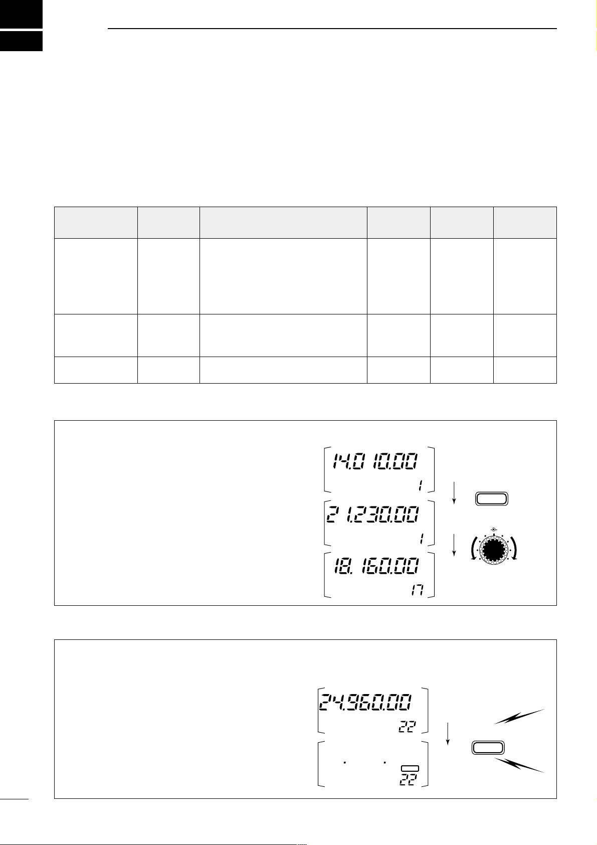
39
5
MEMORY AND SCAN OPERATION
■ Memory channels
The transceiver has 105 memory channels (plus 2 call
channels). Memory mode is useful for quickly changing to often-used frequencies.
All 105 memory channels are tuneable which means
the programmed frequency can be tuned temporarily
with the main dial, etc., in memory mode.
➀ Select M2 functions.
• Push [DISPLAY] 1 or 2 times to select M.
• Push [MENU] one or more times to select
M2.
➁ Push [(F-3)V/M] to select memory mode.
➂ Rotate [M-CH] to select the desired memory chan-
nel.
• All memory channels including blank channels can be
selected.
• [UP]/[DN] on the microphone changes the frequency.
➃ To return to VFO mode, push [(F-3)V/M] again.
Any unnecessary memory channels can be cleared.
The cleared memory channels become blank channels.
➀ Push [(F-3)V/M] in the M2 display to select mem-
ory mode.
➁ Rotate [M-CH] to select a memory channel to be
cleared.
➂ Push [MCL(F-2)] for 2 sec. to clear the contents.
• The programmed frequency and operating mode disappear and “
}” appears.
➃ To return to VFO mode, push [(F-3)V/M] again.
■ Memory channel selection
■ Memory clearing
Note: During split frequency operation, programmed
memory contents can be called up to the SUB readout
(dot matrix portion of the display).
CW
CH
VFO A
[EXAMPLE]: Selecting memory channel 17.
V/M
F-3
USB
CH
MEMO
SPLIT
CH
MEMO
USB
M-CH SHIFT
MCL
F-2
SPLIT
Push for
2 sec.
CH
MEMO
USB
CH
MEMO
BLANK
MEMORY
CHANNEL
MEMORY
CHANNEL
NUMBER
CAPABILITY
TRANSFER
TO VFO
OVER-
WRITING
CLEAR
Regular
(split memory)
1–99
Independent transmit and receive
frequencies and one mode in each
memory channel.
In addition, tone frequencies (or
1750 Hz tone burst) can also be
stored for repeater use.
Yes Yes Ye s
Scan edges
1A–3B
(3 pair)
One frequency and one mode in
each memory channel as scan
edges for programmed scan.
Yes Yes No
Call channel
(split memory)
C1 (144 MHz)
C2 (430 MHz)
Same as regular, but only 144/430
MHz band can be programmed.
Yes Yes No
Page 43
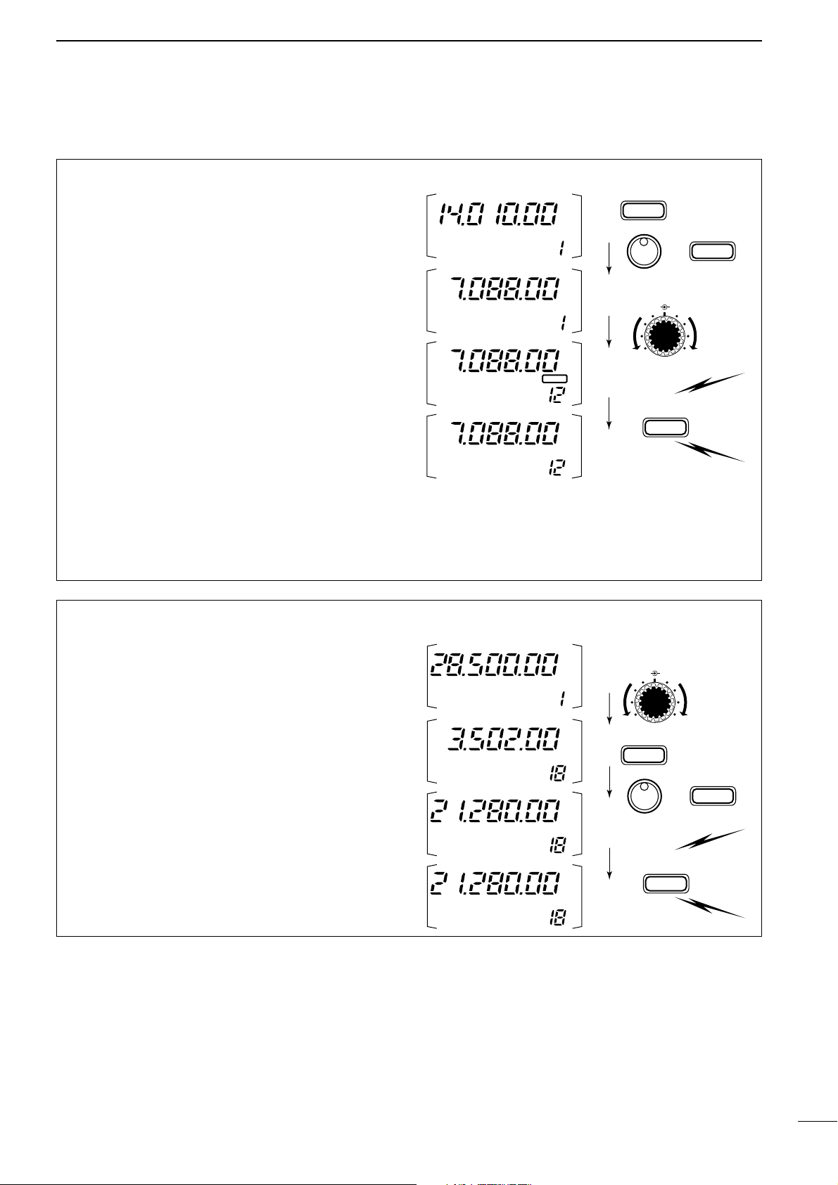
40
5
MEMORY AND SCAN OPERATION
• Programming in VFO mode
➀ Select M2 functions.
• Push [DISPLAY] 1 or 2 times to select M.
• Push [MENU] one or more times to select the
M2 func-
tions.
➁ Set the desired frequency and operating mode in
VFO mode.
• If you want to program the split frequency function, program both receive and transmit frequencies into VFO A
and B, then turn ON the split function.
• If you want to program a repeater function, set a tone
frequency (p. 49) in addition to the receive/transmit frequencies.
➂ Rotate [M-CH] to select the desired memory chan-
nel, or the call channel (144/430 MHz bands only).
•
Select memory mode to confirm the contents, if desired.
•“}” appears if the selected memory channel is a
blank channel (and does not have contents).
➃ Push [(F-1)MW] for 2 sec. to program the displayed
frequency and operating mode into the memory
channel.
To check the programmed contents, push [
(F-3)V/M]
to select memory mode; or, push [CALL] to select the
call channel.
■ Memory/call programming
CW
CH
VFO A
[EXAMPLE]:
Programming 7.088 MHz/LSB into ch 12.
TS
MODE
MW
F-1
LSB
BLANK
SPLIT
CH
VFO A
LSB
CH
VFO A
LSB
CH
VFO A
Push for
2 sec.
M-CH SHIFT
• Programming in memory mode
➀ Set the desired frequency and operating mode.
➁ Select memory mode, then select the desired
memory channel with [M-CH].
• Push [Y]/[Z] when you want to program blank chan-
nels.
➂ Push [(F-1)MW] for 2 sec. to program the displayed
frequency and operating mode into the memory
channel.
CH
[EXAMPLE]:
Programming 21.280 MHz/USB into
ch 18.
TS
MODE
MW
F-1
SPLIT
Push for
2 sec.
CH
MEMO
USB
CH
MEMO
USB
CH
MEMO
CW
CH
MEMO
USB
M-CH SHIFT
Page 44
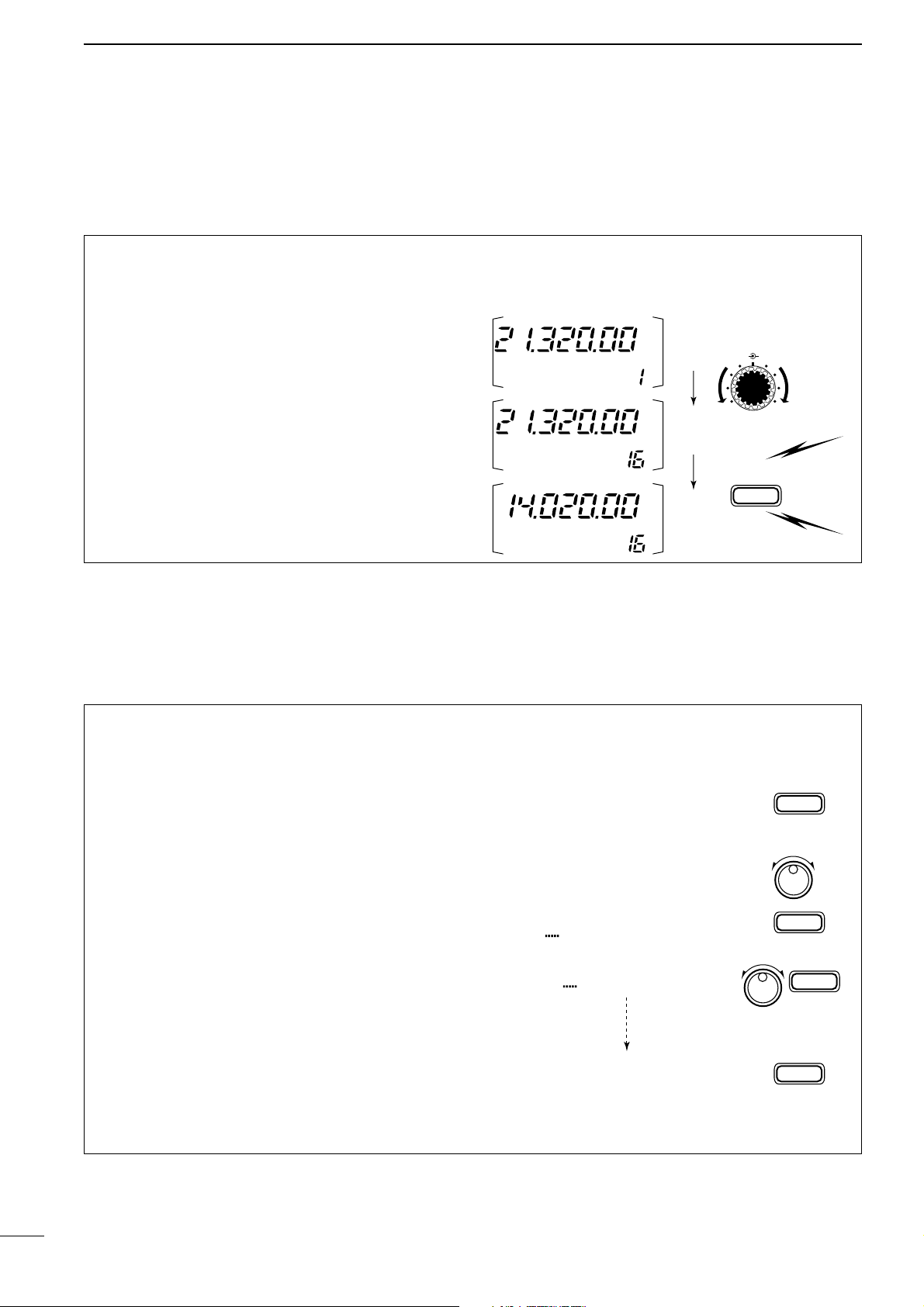
41
5
MEMORY AND SCAN OPERATION
■ Frequency transferring
The frequency and operating mode can be transferred
from memory mode to VFO mode.
➀ Select VFO mode with [(F-3)V/M] in the M2 dis-
play.
➁ Select a memory channel with [M-CH].
• Select memory mode to confirm the memory channel’s
contents, if desired; then return to VFO mode.
•“
}” appears if the selected memory channel is a
blank channel (and does not have contents). In this
case transferring is not possible.
➂ Push [(F-2)MÜV] for 2 sec. to transfer the frequen-
cy and operating mode.
• Transferred frequency and operating mode appear in
the display.
•“
MÜV” does not appear in memory mode.
MÜV
F-2
SPLIT
Push for
2 sec.
[EXAMPLE]: Transferring contents of memory 16.
Operating frequency: 21.320 MHz/USB (VFO)
Contents of memory 16: 14.020 MHz/CW
CH
VFO A
USB
CH
VFO A
USB
CH
VFO A
CW
M-CH SHIFT
■ Memory names
All memory channels (including scan edges and the
call channel) can be tagged with alphanumeric names
of up to 9 characters each.
All common keyboard characters (ASCII characters
33 to 126) can be used, including numerals and punctuation marks.
• Calling up memory names
➀ Select the G4 display.
➥ Push [DISPLAY] 1 or 2 times to select G.
➥ Push [MENU] one or more times to select the
G4 display.
➁ Select a memory channel with [M-CH].
• Editing (programming) memory names
➀ Call up the desired memory (channel) name as
above.
➁ Push [(F-3)É] to enter memory name edit mode.
•“name edit” appears briefly, then a flashing cursor
appears under the first character position.
➂ Rotate the main dial to select the desired charac-
ter, then advance the cursor position.
• [(F-3)Ç] increments the cursor position; [(F-1)Å] decre-
ments the cursor position.
• [(F-2)] overwrites the character with a space.
➃ Repeat this procedure until all desired characters
have been selected.
➄ Push [(MENU)Ä] to exit memory name edit mode.
• The G4 display reappears and the programmed mem-
ory name is displayed.
G4 memory name
G4
G4 Repeater É
ÄÅÖ
name edit
É
F-3
Ç
F-3
Ç
F-3
Ä
MENU
ÄÅR
Ç
Ç
ÄÅRe
Ç
ÄÅRepeaterÖ
Ç
É
Page 45
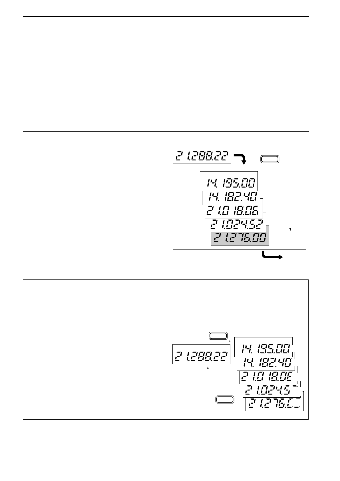
42
5
MEMORY AND SCAN OPERATION
• Calling up a frequency from a memo pad
You can simply call up the desired frequency and
operating mode of a memo pad by pushing
[(F-3)MPR] in the S1 display.
• Make sure S1 is selected in advance.
• Both VFO and memory modes can be use.
• The frequency and operating mode are called up, starting
from the most recently written.
When you call up a frequency and an operating
mode from memo pads with [(F-3)MPR], the previously displayed frequency and operating mode are
automatically stored in a temporary pad. The frequency and operating mode in the temporary pad
can be recalled by pushing [(F-3)MPR] one or more
times.
Note: If you change the frequency or operating mode
called up from a memo pad, the frequency and operating mode in the temporary pad are erased.
VFO or
MEMORY
mode
MEMO PADS
MPR
F-3
MPR
F-3
USB
USB
USB
USB
USB
USB
MP5
MP4
MP3
MP2
MP1
■ Memo pads
The transceiver has a memo pad function to store frequency and operating mode for easy write and recall.
The memo pads are separate from memory channels.
The default number of memo pads is 5, however, this
can be increased to 10 in initial set mode if desired
(p. 53).
Memo pads are convenient when you want to memorize a frequency and operating mode temporarily, such
as when you find a DX station in a pile-up or when a
station is busy for a long time and you want to temporarily search for other stations.
Use the transceiver’s memo pads instead of relying on
hastily scribbled notes that are easily misplaced.
• Writing frequencies and operating modes
into memo pads
➀ Select the S1 display.
• Push [DISPLAY] 1 or 2 times to select S.
• Push [MENU] one or more times to select
S1.
➁ Push [(F-2)MPW] to program the frequency into a
memo pad.
When you write a 6th frequency and operating mode,
the oldest written frequency and operating mode are
automatically erased to make room for the new settings.
Note: Each memo pad must have its own unique
combination of frequency and operating mode;
memo pads having identical settings cannot be written.
Displayed frequency and mode
Push
Newest
MP5
MP4
MP3
MP2
MP1
The oldest written frequency
and mode are erased.
Oldest
MPW
F-2
USB
USB
USB
USB
USB
USB
Page 46

43
5
MEMORY AND SCAN OPERATION
■ Scan types
■ Preparation
• Channels
For programmed scan: Program scan edge frequen-
cies into scan edge memory channels 1A and 1B
(p. 34).
For memory scan: Program 2 or more memory chan-
nels except scan edge memory channels.
For memory select scan: Designate 2 or more memo-
ry channels as select memory channels—select a
memory channel, then push [(F-2)SEL] in the S2 display (memory mode) to designate the channel as a
select memory channel.
For priority watch: Program 1 memory channel to be
watched.
• Scan resume ON/OFF
You can select the scan to resume or cancel when
detecting a signal, in initial set mode, item 21. Scan
resume ON/OFF must be set before operating a scan.
See p. 53 for ON/OFF setting and scan resume condition details.
• Scan speed
Scan speed can be selected from 2 levels, high or low,
in initial set mode. See p. 47 for details.
• Squelch condition
PROGRAMMED SCAN
Repeatedly scans between two scan edge frequencies
(scan edge memory channels 1A and 1B).
This scan operates in VFO mode.
SELECTED MEMORY SCAN
Repeatedly scans all selected memory channels.
PRIORITY WATCH
Checks for signals on a memory or call channel while
operating on a VFO frequency.
This scan operates in memory mode.This scan operates in memory mode.
This scan operates in VFO mode.
Scan
Scan edge 1A or 1B Scan edge 1B or 1A
Jump
Mch 1 Mch 5
Memory channel watch Call channel watch
Memory
channel
VFO
frequency
Mch 2 Mch 3 Mch 4
Mch 6Mch 7Mch 99
MEMORY SCAN
Repeatedly scans all programmed memory channels.
Mch 1 Mch 5
Mch 2 Mch 3 Mch 4
Mch 6Mch 7Mch 99
BLANK
S (select)
S (select)S (select)
S (select)
S (select)
S (select)
S (select)S (select)
S (select)
S (select)
BLANK
Call
channel
VFO
frequency
SCAN
STARTS
WITH
PROGRAMMED
SCAN
MEMORY SCANS
PRIORITY WATCH
SQUELCH
OPEN
The scan continues
until it is stopped
manually, and does
not pause even if it
detects signals.
This is not applicable
when the scan
resume is OFF and a
programmable step
(more than 1 kHz) is
selected.
Scan pauses on each
channel when the
scan resume is ON;
not applicable when
OFF.
SQUELCH
CLOSED
Scan stops when detecting a signal.
If you set scan resume ON in initial set mode,
the scan pauses for 10 sec. when detecting a
signal, then resumes. When a signal disappears while scan is paused, scan resumes 2
sec. later.
Page 47

44
5
MEMORY AND SCAN OPERATION
➀ Select VFO mode, then set a frequency.
➁ Close the squelch with [SQL].
➂ Set the desired memory channel as the watching
channel.
➃ Select S2, then push [(F-2)PRI] to start the watch.
• Decimal point blinks while scanning.
➄ When the scan detects a signal, the scan pauses
for 10 sec. or until the signal disappears, depending on the resume setting.
➅ To cancel the scan push [(F-2)PRI].
Note: The paused condition when detecting a signal
differs depending on the scan resume condition.
resume on: pauses for 10 sec.
resume off: pauses until the signal disappears.
➀ Select memory mode.
➁ Close the squelch with [SQL].
➂ Select S2, then push [(F-1)SCN] to start the mem-
ory scan.
• Decimal point blinks while scanning.
➃ Push [(F-2)SEL] to change the memory scan to
select memory scan.
• Push [(F-2)SEL] for 2 sec. to clear all select memory
channels.
➄ When the scan detects a signal, the scan stops or
pauses depending on the resume setting.
➅ To cancel the scan push [(F-1)SCN].
Note: Two or more memory channels must be designated as select memory channels for select memory
scan to start.
S2 SCN
SEL V/M
Select
memory mode
Designate
“S.”
F-1
F-2
Push [(F-1)SCN], then [(F-2)SEL].
CH
S
MEMO
PO
S1
5
537920401060dB
USB
➀ Select memory mode.
➁ Close the squelch with [SQL].
➂ Select S2, then push [(F-1)SCN] to start the scan.
• Decimal point blinks while scanning.
➃ When the scan detects a signal, the scan stops or
pauses depending on the resume setting.
➄ To cancel the scan push [(F-1)SCN].
Note: Two or more memory channels must be programmed for memory scan to start.
S2 SCN
SEL V/M
Select
memory mode
F-1
then push [(F-1)SCN]
CH
MEMO
PO
S1
5
537920401060dB
USB
➀ Select VFO mode.
➁ Select the desired operating mode.
• The operating mode can also be changed while scanning.
➂ Set [SQL] open or closed.
• See page a left for squelch condition.
➃ Select S2, then push [(F-1)SCN] to start the scan.
• Decimal point blinks while scanning.
➄ When the scan detects a signal, the scan turns
OFF, pauses or ignores it depending on the
resume setting and the squelch condition.
• During scan [TS] can be used only when resume is ON.
➅ To cancel the scan push [(F-1)SCN].
Note: If the same frequencies are programmed into
the scan edge memory channels 1A and 1B, programmed scan does not start.
■ Programmed scan operation
■ Memory scan operation
■ Select memory scan operation
S2 SCN
PRI V/M
Select
VFO mode
Select watching
channel
F-2
Push [(F-2)PRI].
CH
PO
S1
5
537920401060dB
USB
VFO A
■ Priority watch
CH
VFO A
PO
S1
5
537920401060dB
USB
S2 SCN PRI V/M
Select
VFO mode
F-1
then push [(F-1)SCN]
Page 48
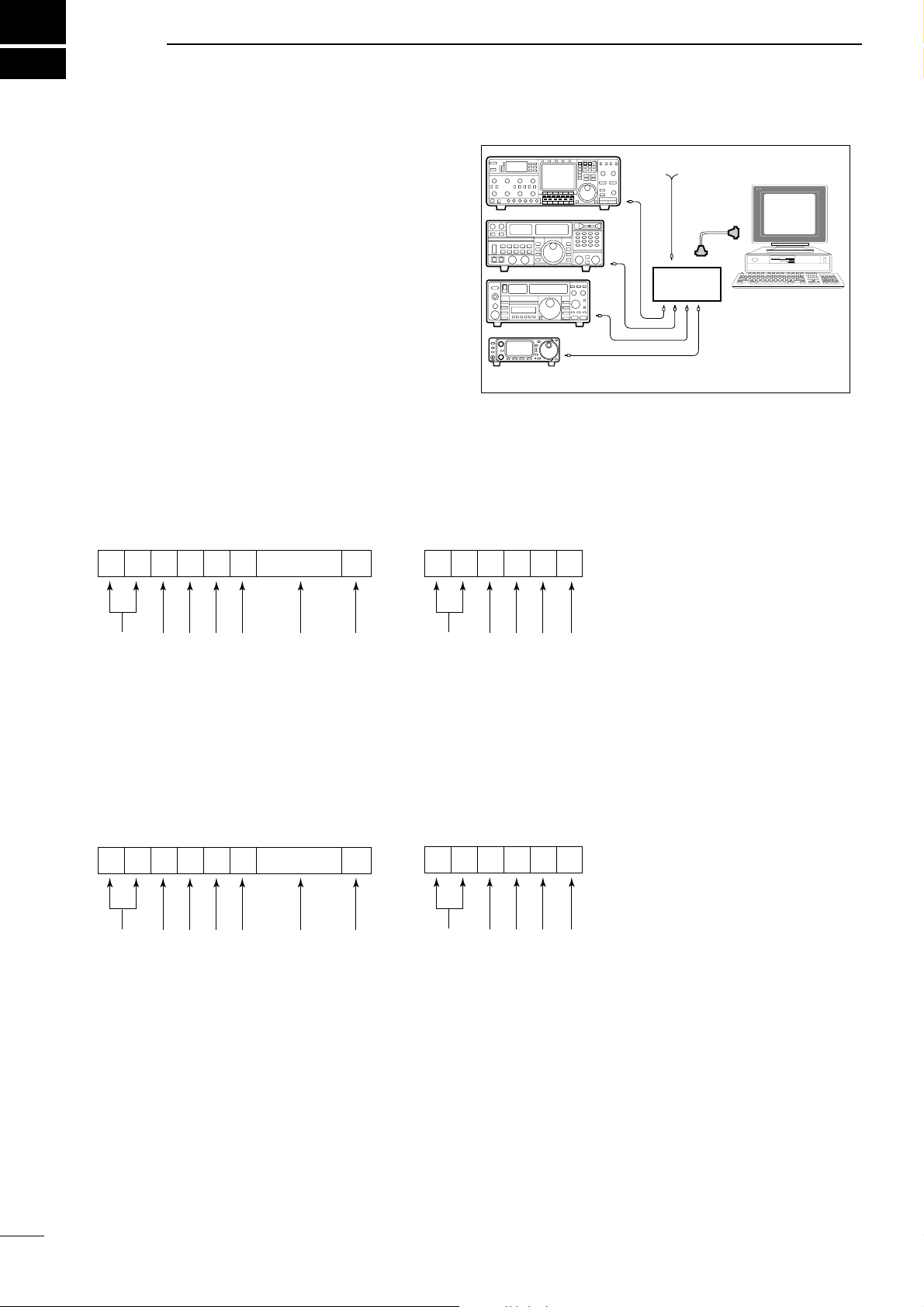
45
6
REMOTE JACK (CI-V) INFORMATION
D CI-V connection example
The transceiver can be connected through an optional CT-17 CI-
V LEVEL CONVERTER
to a personal computer equipped with an RS-232C port. The Icom
Communication interface-V (CI-V) controls the following functions of the transceiver.
Up to four Icom CI-V transceivers or receivers can be
connected to a personal computer equipped with an
RS-232C port. See p. 55 for setting the CI-V condition
using initial set mode.
D Data format
The CI-V system can be operated using the following
data formats. Data formats differ according to command numbers. A data area is added for some commands.
Personal
computer
IC-706MKIIG
CT-17
9–15 V DC
CONTROLLER TO IC-706MKIIG
FE FE 58 E0 Cn Sc Data area FD
(see table at right)
(see table at right)
Command number
Preamble code (fixed)
Controller’s default address
Transceiver’s default address
Sub command number
IC-706MKIIG TO CONTROLLER
FE FE E0 58 Cn Sc Data area FD
OK MESSAGE TO CONTROLLER
FE FE 58 E0 FB FD
memory number entry
End of message code (fixed)
BCD code data for frequency or
NG MESSAGE TO CONTROLLER
FE FE 58 E0 FA FD
OK code (fixed)
Preamble code (fixed)
Controller’s default address
Transceiver’s default address
End of message code (fixed)
Command number
Preamble code (fixed)
Controller’s default address
Transceiver’s default address
(see table at right)
(see table at right)
Sub command number
BCD code data for frequency or
memory number entry
End of message code (fixed)
NG code (fixed)
Preamble code (fixed)
Controller’s default address
Transceiver’s default address
End of message code (fixed)
Page 49

46
6
REMOTE JACK (CI-V) INFORMATION
*1When wide or normal operation is available, add “00” for wide oper-
ation or “01” for normal operation; when normal or narrow operation
is available, add “00” for normal operation or “01” for narrow operation; when wide, normal and narrow operation is available, add “00”
for wide operation, “01” for normal operation and “02” for narrow
operation.
*2Memory channel number 1A=0100/1b=0101, 2A=0102/2b=0103,
3A=0104/3b=0105, C1=0106, C2=0107.
COMMAND TABLE
Cn Sc Description
00 — Send frequency data
01 xx Send mode data
02 — Read band edge frequencies
03 — Read display frequency
04 — Read display mode
05 — Set frequency data
00*
1
Set LSB
01*
1
Set USB
02*
1
Set AM
06 03*
1
Set CW
04*
1
Set RTTY
05*
1
Set FM
06*
1
Set WFM
— Set to VFO
00 Set to VFO A
07 01 Set to VFO B
A0 VFO A=B
B0 Switch VFO A and B
08
— Set to memory mode
mc*
2
Mch
09 — Memory write
0A — Memory to VFO
0B — Memory clear
0C — Read duplex offset frequency
0D — Set duplex offset frequency
Cn Sc Description
0E
00 Scan stop
01 Scan start
00 Split OFF
01 Split ON
0F 10 Simplex mode
11 Duplex mode
12 Duplex + mode
00 10 Hz TS
01 100 Hz TS
02 1 kHz TS
03 5 kHz TS
04 9 kHz TS
10 05 10 kHz TS
06 12.5 kHz TS
07 20 kHz TS
08 25 kHz TS
09 100 kHz TS
11 xx ATT ON/OFF; 00=OFF; 20=ON
15
01 Read squelch condition
02 Read S-meter level
02 Preamp setting
12 AGC setting
16 22 NB setting
42 TONE setting
43 TSQL setting
44 COMP setting
46 VOX setting
47 BK-IN setting
19 00 Read transceiver ID code
Page 50

47
7
SET MODE
■ General
Set mode is used for programming infrequently
changed values or conditions of functions. The IC-
706MKIIG has 2 separate set modes: quick set mode
and initial set mode.
D Quick set mode operation
➀ While power is ON, push [DISPLAY] for 2 sec.
• Quick set mode is selected and one of its items appears.
• Quick set mode items vary depending on the operating
mode (SSB, FM, etc.) selected.
➁ Push [MENU] one or more times to select the
desired item.
• [M-CH] or [Y]/[Z] can also be used.
➂ Rotate the main dial to set the values or conditions
for the selected item.
➃ Repeat steps ➁ and ➂ to set other items.
➄ To exit quick set mode, push [DISPLAY] momentar-
ily.
D Initial set mode operation
➀ Push [POWER] for 2 sec. to turn power OFF.
➁ While pushing [LOCK] push [POWER] to turn power
ON.
• Initial set mode is selected and one of its items appears.
➂ Push [MENU] one or more times to select the
desired item.
• [M-CH] or [Y]/[Z] can also be used.
➃ Rotate the main dial to set the values or conditions
for the selected item.
➄ Repeat steps ➂ and ➃ to set other items.
➅ To exit initial set mode, push [POWER] for 2 sec. to
turn power OFF.
➆ Push [POWER] to turn power ON again.
• The conditions selected in initial set mode are now effective.
[POWER]
[MENU] [LOCK]
Main dial
Item number
Item
Value or
condition
1
MODE SELECT
[DISPLAY EXAMPLE: INITIAL SET MODE]
[M-CH]
[Y]
[Z]
Q1 RF POWER
USB
[POWER]
[MENU]
[M-CH]
[DISPLAY]
Main dial
[Y]
[Z]
Item number
Item
Value or
condition
[DISPLAY EXAMPLE: QUICK SET MODE]
PO
S1
5
537920401060dB
Page 51

48
7
SET MODE
Q4 RTTY KEYING (RTTY only)
This item adjusts the RTTY keying. Normal or
reverse keying can be selected.
The default is “n,” normal.
Normal : key open=mark
Reverse : key open=space
RTTY
■ Quick set mode items
Q1 RF POWER (all modes)
This item adjusts the RF output power. The RF output power can be adjusted from L, 1 to 9 and H for
indication, however, it can be adjusted continuously.
Q2 MIC GAIN (SSB/AM/FM only)
This item adjusts microphone gain from 1 to 10 for
indication, however, it can be adjusted continuously.
The default is 5.
Note that while adjusting mic gain, the
ALC meter is displayed automatically.
The default is H (maximum power).
Note that while adjusting the output
power, the power meter is displayed
automatically.
Q2 CW PITCH (CW only)
This item adjusts the CW pitch. CW pitch is
adjustable from 300 to 900 Hz in 10 Hz steps.
The default is 600 Hz.
CW
Q2 RTTY TONE (RTTY only)
This item selects the RTTY tone. RTTY tone is toggled between 1275, 1615 and 2125 Hz.
The default is 2125 Hz.
RTTY
Q3 VOX DELAY (SSB/AM/FM only)
This item adjusts the VOX (Voice-activated Transmit)
delay time. The delay time can be adjusted from 0 to
2 sec. in 0.1 sec. units.
The default is 1.0 seconds.
USB
Q3 BK-IN DELAY (CW only)
This item adjusts break-in delay time for CW semi
break-in operation. The delay time is selectable from
2.0 to 13.0 (dots).
The default is 7.5 dots.
CW
Q3 RTTY SHIFT (RTTY only)
This item adjusts the RTTY shift. There are 3 selectable values: 170, 200 and 425 Hz.
The default is 170 Hz.
RTTY
Q4 VOX GAIN (SSB/AM/FM only)
This item adjusts the VOX gain for the VOX (voice
activated transmit) function.
USB
The default is 5.
Page 52

49
7
SET MODE
Q6 CARRIER Frq (SSB only)
This item adjusts the carrier frequency (BFO frequency), allowing you to change the audio characteristics.
Selectable values are –200 to +200 Hz in 10 Hz steps.
USB
The default is 0 Hz.
Q6 RPTR TONE (FM only)
This item selects a subaudible tone for FM-T mode
operation to access a repeater. There are 50 tones
available from 67.0 Hz to 254.1 Hz (see table at
right).
• Available subaudible tones Unit: Hz
The default is 88.5 Hz.
FM
Q4 CW PADDLE (CW only)
This item adjusts the CW paddle type. Four selections are available.
• n : normal (for electronic keyer use)
• r : reverse (for electronic keyer use)
• buG : When using the electronic key, key down
produces a “dash,” releasing the key automatically produces a “dot(s).”
• oFF : Turns OFF the electronic keyer (for
straight key use)
• ud : For using the microphone’s [UP]/[DN]
keys instead of the CW paddle.
The default is “n,” normal.
CW
Q5 KEY SPEED (CW only)
This item adjusts the CW key speed. The key speed
can be selected from 6 to 60 wpm.
The default is 20 wpm.
CW
Q6 RATIO (CW only)
This item adjusts the CW key ratio (or weight). The
ratio can be selected from 2.8 to 4.5.
The default is 3.0.
CW
Q7 TONE SQL (FM only)
This item adjusts sets a subaudible tone for tone
squelch use. (the same subaudible tone frequencies
as for repeater operation are available—see above).
The default is 88.5 Hz.
FM
67.0 79.9 94.8 110.9 131.8 156.7 171.3 186.2 203.5 229.1
69.3 82.5 97.4 114.8 136.5 159.8 173.8 189.9 206.5 233.6
71.9 85.4 100.0 118.8 141.3 162.2 177.3 192.8 210.7 241.8
74.4 88.5 103.5 123.0 146.2 165.5 179.9 196.6 218.1 250.3
77.0 91.5 107.2 127.3 151.4 167.9 183.5 199.5 225.7 254.1
Q5 ANTI VOX (SSB/AM/FM only)
This item adjusts the ANTI-VOX gain for the VOX
(voice activated transmit) function.
USB
The default is 5.
Page 53

50
7
SET MODE
4 BACK LIGHT (display backlighting)
The function display backlighting can be set to high,
low or OFF to suit ambient lighting.
Display backlighting set to
high (default).
Display backlighting set to
low.
5 KEY LIGHT (key/switch backlighting)
The key/switch backlighting can be set to high, low or
OFF to suit ambient lighting.
Display backlighting set to
high (default).
Display backlighting set to
low.
■ Initial set mode items
2 BEEP (confirmation beep)
A beep sounds each time a switch is pushed to confirm it. This function can be turned OFF for silent
operation.
3 BAND BEEP (band beep)
A beep sounds when an operating frequency enters
or exits a transmit frequency range. This functions
independent of the confirmation beep setting (above).
Confirmation beep ON
(default)
Confirmation beep OFF
Band beep ON
(default)
Band beep OFF
1 MODE SELECT (all modes)
This item is available in all modes, and allows you to
simplify operation by inhibiting the selection of
unneeded operating modes during normal operation.
For example if you are operating mobile and only
plan on using FM and AM modes, use “MODE
SELECT” to inhibit access to all other modes (SSB,
CW, RTTY, WFM), thereby making selection of AM or
FM quick and easy.
The default is on for all operating
modes. To toggle an operating mode
on or off, push (or push and hold)
[MODE] one or more times until the
desired mode is displayed, then rotate
the main dial to set on or off.
Q8 RPTR-T SCN (repeater tone scan)
During repeater operation, you can detect the tone
frequency necessary to open a repeater (see p. 30).
The default is 88.5 Hz.
FM
Q8 T-SQL SCN
(tone squelch tone scan)
During tone squelch operation, you can detect the
tone frequency necessary to communicate using
tone squelch (see p. 31).
The default is 88.5 Hz.
FM
Page 54

51
SET MODE
7
11 PEAK HOLD (peak hold)
When the peak hold function is ON, the highest activated segment of the meter remains visible for 0.5
sec.; when OFF, the meter functions normally.
Peak hold ON
(default)
Peak hold OFF
6 AUTO OFF (auto power OFF)
The auto power OFF function can be used to automatically turn the transceiver OFF after a specified
time of operation. This item can be set to 30 min., 60
min., 90 min., 120 min., or OFF.
Auto power OFF set to
20 min.
Auto power OFF
deactivates. (default)
7 RF/SQL (SQL/AUTO/RF•SQL)
The [RF/SQL] control can be set as the squelch control (default), the RF/squelch control (USA version
default) or automatic (acts as squelch in
FM/WFM/AM modes; as RF in SSB/CW/RTTY
modes). (See p. 22)
The [RF/SQL] control
functions as RF gain
control only.
The [RF/SQL] control
functions as squelch
control only.
8 SUBDIAL (Subdial function)
When this item is set to “rit,” pushing [RIT/SUB]
turns the RIT function ON (lights red)—rotating [MCH] changes the RIT frequency; when this item is set
to “Freq,” pushing [RIT/SUB] turns the sub dial function ON (lights green)—rotating [M-CH] changes the
operating frequency. Note that in FM, WFM and AM
modes, pushing [RIT/SUB] always selects the sub
dial function (lights green), regardless of this setting.
Pushing [RIT/SUB]
selects the RIT function
(default).
Pushing [RIT/SUB]
selects the sub dial function.
9 OPT. FIL 1 (optional filter)
When an optional filter is installed, this selection is
necessary, otherwise the filters cannot be selected.
Selections available are FL-100, FL-101, FL-103,
FL-223, FL-232 and none (default). See p. 22 for
usable filters for each mode and see p. 60 for filter
installation.
10 OPT. FIL 2 (optional filter)
When an optional filter is installed, this selection is
necessary, otherwise the filters cannot be selected.
Selections available are FL-100, FL-101, FL-103,
FL-223, FL-232 and none (default). See p. 22 for
usable filters for each mode and see p. 60 for filter
installation.
No filters are selected
(default).
FL-223 (for LSB/USB mode)
is selected.
No filters are selected
(default).
FL-223 (for LSB/USB mode)
is selected.
Page 55

52
15 DUP HF (duplex offset)
This item sets the offset for the duplex function when
operating on the HF bands.
Default is 0.100 MHz.
16 DUP 50M (duplex offset)
This item sets the offset for the duplex function when
operating on the 50 MHz band.
Default is 0.500 MHz.
17 DUP 144M (duplex offset)
This item sets the offset for the duplex function when
operating on the 144 MHz band.
Default is 0.600 MHz.
18 DUP 430M (duplex offset)
This item sets the offset for the duplex function when
operating on the 430 MHz band.
Default is 5.000 MHz.
19 1TOUCH RPTR
(one touch repeater)
This item sets the offset direction when using the
one-touch repeater function. +duplex or –duplex can
be selected.
Duplex direction is set
to –duplex.
Duplex direction is set to
+duplex.
DUP DUP
14 SPL OFFSET (split offset)
This item sets the offset (difference between transmit
and receive frequencies) for the quick split function.
Note that this setting is not valid in FM/WFM modes.
Default is 0.100 MHz.
13 SPLIT LOCK (split lock)
When this item is ON the main dial can be used to
adjust the transmit frequency (XFC) even while the
lock function is activated.
Split lock function OFF
(default)
Split lock function ON
12 QUICK SPLIT
(quick split function
)
When this item is set to ON, pushing [SPL] for 2 sec.
sets the undisplayed VFO frequency to the displayed
VFO frequency plus the split offset or duplex offset,
and activates split operation.
Quick split function ON
(default).
Quick split function OFF.
7
SET MODE
Page 56

53
SET MODE
7
26 PWR ON CHK (Power on check)
When this item is set to “on,” the set output power is
briefly displayed when turning power ON (RIT and
auto power off settings are also displayed if activated); when turned “oFF,” the display goes directly to
frequency indication at power ON.
Power on check ON
(default)
Power on check OFF
24 AM NB (Noise blanker in AM mode)
When this item is set to ON, the noise blanker function is available in AM mode. This is useful when
communicating in AM mode (the noise blanker function should not be used when listening to regular AM
broadcasts as it may degrade the received audio).
Noise blanker available
(default)
Noise blanker not available
20 AUTO RPTR
(auto repeater
)
When this item is set to “on 1”, the tone encoder is
not set when the auto repeater is activated; when set
to “on 2” the auto repeater function also sets the tone
encoder on.
Auto repeater function OFF
(default).
Auto repeater function ON,
tone encoder OFF.
22 SCAN SPEED (scan speed)
This item sets the rate at which channels or frequencies are scanned during scan operations. High or low
can be selected.
23 U/D SPEED (up/down speed)
This item sets the rate at which frequencies are
scanned through when the [UP]/[DN] switches are
pushed and held. High or low can be selected.
Scan speed is set to high
(default).
Scan speed is set to low.
Up/down speed is set to
high (default).
Up/down speed is set to low.
21 SCAN RESUME (scan resume)
This item sets the scan resume function ON or OFF.
ON: scan resumes 10 sec. after stopping on a signal
(or 2 sec. after a signal disappears); OFF: scan does
not resume after stopping on a signal. For the priority watch, setting to OFF pauses the watch until signal disappears and scan resumes.
Scan resume function is
turned ON (default).
Scan resume function is
turned OFF.
25 PAD CH (available memo pads)
This item sets the number of memo pad channels
available. 5 or 10 memo pads can be set.
5 memo pads are available
(default).
10 memo pads are available.
Page 57

54
29 9600 MODE
(Data socket speed)
This is used to change the communications speed
packet operation. The data socket can be set to 1200
or 9600 baud.
Default is 9600 baud.
30 VSEND SEL
(ACC socket output)
“on”: VSEND is for 144/430 MHz; HSEND is for
the HF/50 MHz
“U only”: VSEND is for 430 MHz; HSEND is for
HF/50/144 MHz
“oFF”: VSEND is not used; HSEND is for all
bands.
The default is VSEND is for the 144/430 MHz band;
HSEND is for the HF/50 MHz band.
31 SPEECH LANG
When the optional UT-102
VOICE SYNTHESIZER UNIT
is
installed, you can select between English and
Japanese as the language.
32 SPEECH SPD
When the optional UT-102
VOICE SYNTHESIZER UNIT
is
installed, you can select between faster or slower
synthesizer output.
Voice synthesizer functions
in English (default).
Voice synthesizer functions
in Japanese.
Voice synthesizer output
is faster (default).
Voice synthesizer output
is slower.
(voice synthesizer language)
(voice synthesizer speed)
28 PTT TUNE
(PTT tune function)
When an optional AH-4
ANTENNA TUNER
is connected, tuning can be started automatically at the
moment the PTT is pushed.
27 A-TUNE STRT
(auto tuner start)
The optional AT-180
ANTENNA TUNER
has an automatic start capability which starts tuning if the SWR
is higher than 1.5–3.
When “oFF” is selected, the tuner remains OFF even
when the SWR is poor (1.5–3).
When “on” is selected, automatic tune starts even
when the tuner is turned OFF.
Note: Even when “on” is selected, automatic tune
does not start for the 50 MHz band.
Auto tune function OFF
(default).
Auto tune function ON.
Tuning starts when pushing [PTT]
on a new frequency.
Tuning starts only when
[TUNER] is pushed
(default)
.
7
SET MODE
Page 58

55
7
SET MODE
33 S-LVL SPCH (S-level speech)
When an optional UT-102
SPEECH SYNTHESIZER UNIT
is installed, the synthesizer can be set to read out the
frequency/mode only, or both the frequency/mode
and S-meter level.
Voice synthesizer reads out
both the frequency/mode
and S-meter level (default).
Voice synthesizer reads out
the frequency/mode only.
37 CI-V 731 (CI-V operating fre-
quency data length)
When connecting the IC-706MKIIG to the IC-735 for
transceive operation, you must change the operating
frequency data length to 4 bytes.
• This item
MUST
be set to “on” only when operating trans-
ceiver with the IC-735.
Frequency data set to
5 bytes (default).
Frequency data set to
4 bytes.
36 CI-V TRN (CI-V transceive)
Transceive operation is possible with the IC706MKIIG connected to other Icom HF transceivers
or receivers. When “on” is selected, changing the
frequency, operating mode, etc. on the IC-706MKIIG
automatically changes those of connected transceivers (or receivers) and vice versa.
Transceive ON
(default)
Transceive OFF
34 CI-V ADDRES (CI-V address)
To distinguish equipment, each CI-V transceiver has
its own Icom standard address in hexadecimal code.
The IC-706MKIIG’s address is 4EH.
When 2 or more IC-706MKIIG’s are connected to an
optional CT-17
CI-V LEVEL CONVERTER
, rotate the
main dial to select a different address for each IC706MKIIG in the range 01H to 7FH.
35 CI-V BAUD (CI-V data rate)
This item sets the data transfer rate. When “Auto” is
selected, the baud rate is automatically set according
to the connected controller or remote controller.
Address set to 58H
(default).
Address set to 7FH.
Auto baud rate
(default)
19200 bps
Page 59

56
8
MAINTENANCE
If the transceiver becomes dusty or dirty,
wipe it clean with a dry, soft cloth.
AVOID the use of strong chemical solvents
such as thinner, benzine or alcohol to clean
the transceiver. These may damage the
transceiver’s surfaces.
■ Fuse replacement
If a fuse blows or the transceiver stops functioning, try
to find the source of the problem, and replace the
damaged fuse with a new, rated fuse.
Caution: Disconnect the DC power cable from the
transceiver when changing a fuse.
The IC-706MKIIG has 2 types of fuses installed for
transceiver protection.
• DC power cable fuses ...................................... 30 A
• Circuitry fuse ............................. F.G.M.B. 125 V 4 A
DC POWER CABLE FUSE REPLACEMENT
30 A fuse
CIRCUITRY FUSE REPLACEMENT
The 13.8 V DC from the DC power cable is applied to
all units in the IC-706MKIIG, except for the power
amplifier, through the circuitry fuse. This fuse is
installed in the PA unit.
■ Memory backup
All of the CPU’s memory is backed up by an EEPROM (Electronically-Erasable Programmable ReadOnly Memory). All data you set, such as VFO, memory, set mode contents, etc. is stored in this EEPROM. There is no internal lithium battery.
■ Cleaning
4 A Fuse
Page 60
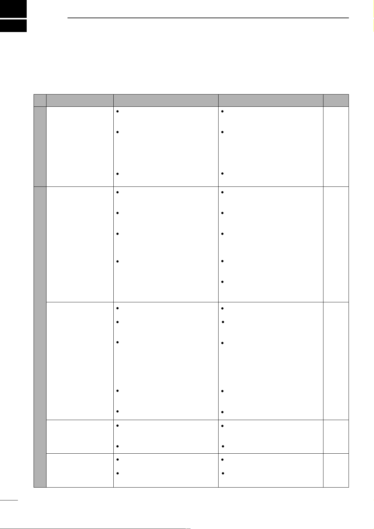
57
9
TROUBLESHOOTING
The following chart is designed to help you correct
problems which are not equipment malfunctions.
If you are unable to locate the cause of a problem or
solve it through the use of this chart, contact your
nearest Icom Dealer or Service Center.
PROBLEM
POWER SUPPLY
RECEIVE
POSSIBLE CAUSE SOLUTION REF.
Power does not come
on when the [POWER]
switch is pushed.
No sound comes from
the speaker.
Sensitivity is low.
Receive audio is distorted.
Receive signal is distorted with strong signals.
DC power cable is improperly
connected.
Fuse is blown.
Battery is exhausted if you are using
a 12 V battery as the power source.
Reconnect the power cable correctly.
Check for the cause, then replace the
fuse with a spare one.
(Fuses are installed in two places. One is
installed in the DC power cable and the
other is installed in the PA unit.
Check the battery voltage with the
[POWER] pushed IN.
p. 13
p. 56
—
p. 1
p. 1
—
p. 12
p. 12
—
—
p. 14
pgs. 27,
28
p. 21
p. 19
p. 20
p. 21
p. 21
Volume level is set too low.
The squelch is closed.
The transceiver is in the transmitting
condition.
An external speaker or headphones
are connected.
The antenna is not connected properly.
The antenna feed line is cut or shorted.
The antenna for another band is
selected.
The antenna is not properly tuned.
The attenuator function is activated.
The operating mode is not selected
correctly.
The [SHIFT] control is set off-center.
Noise blanker function is activated.
Preamp is activated.
Rotate [AF] clockwise to obtain a suitable listening level.
Rotate [SQL] counterclockwise to
open the squelch.
Release [PTT] on the microphone or
check the SEND line of an external
unit, if connected.
Check the external speaker or headphone plug connection.
Check the speaker ON/OFF switch or
speaker A/B switch, when an optional
SP-20
EXTERNAL SPEAKER is in use.
Reconnect to the antenna connector.
Check the feed line and correct any
improper conditions.
Select an antenna suitable for the
operating frequency.
Make sure that [ANT1] is used for
frequencies less than 60 MHz and
[ANT2] is used for frequencies of 60
MHz and above.
Push [TUNE] to manually tune the
antenna.
Push [ATT] to turn the function OFF.
Select a suitable operating mode.
Set [SHIFT] to the center position.
Push [NB] to turn the function OFF.
Push [P.AMP] to turn the function
OFF.
Page 61

58
9
TROUBLESHOOTING
PROBLEM
TRANSMITDISPLAYSCAN
POSSIBLE CAUSE SOLUTION REF.
Transmitting is impossible.
Output power is too low.
No contact possible with
other stations.
Repeater cannot be accessed.
Transmitted signals are
distorted.
Displayed frequency
does not change properly.
Programmed scan does
not stop.
Programmed scan does
not start.
Memory scan does not
start.
Memory select scan
does not start.
The operating frequency is not set to
a ham band.
Power is set to a lower power than
maximum.
Microphone gain is set too low.
The antenna is not connected properly.
The antenna feed line is cut or shorted.
An antenna for another band is selected.
The antenna is not properly tuned.
RIT function is activated.
Split function is activated.
Split function is not activated.
An incorrect transmit frequency is set.
Subaudible tone encoder is OFF and
repeater requires a tone for access.
Programmed subaudible tone frequency is wrong.
Microphone gain is set too high.
[COMP LEVEL] is rotated too far
clockwise with the speech compressor ON.
The dial lock function is activated.
The internal CPU has malfunctioned.
Squelch is open.
The same frequencies have been
programmed in scan edge memory
channels.
2 or more memory channels have not
been programmed.
2 or more memory channels have not
been designated as select channels.
Set squelch to the threshold position.
Programm different frequencies into
scan edge memory channels.
Program 2 or more memory channels.
Designate 2 or more memory channels as select channels for the scan.
Set gain in quick set mode.
Set [COMP LEVEL] to a suitable position.
Push [LOCK] to deactivate the function.
Reset the CPU.
(While pushing [UP] and [DN] push [POWER] to turn power ON.
Push [DUP] to turn the function ON
.
Set the proper frequencies into VFO
A and B or into one of the memory
channels.
Use [TON] to select FM-T.
Program the required frequency using
quick set mode.
Push RIT to turn the function OFF.
Push [SPLIT] to turn the function OFF.
Set the output power in quick set
mode.
Set microphone gain to a suitable
position using quick set mode.
Reconnect the antenna connector.
Check the feed line and correct any
improper conditions.
Select an antenna suitable for the operating frequency.
Push [TUNE] to manually tune the
antenna when an optional antennal
tuner is connected.
Set the frequency to a ham band.
p. 17
p. 44
p. 44
—
—
p. 14
pgs. 27,
28
p. 20
p. 29
p. 29
p. 17
p. 30
p. 49
p. 48
p. 5
p. 2
p. 15
p. 23
p. 44
p. 41
p. 44
Page 62

59
10
OPTIONAL INSTALLATIONS/SETTINGS
■ Opening the transceiver case
To remove the transceiver case unscrew the 10
screws (5 in the top panel and 5 in the bottom panel)
as shown in the diagram below.
■ UT-102
VOICE SYNTHESIZER UNIT
The UT-102 announces the accessed band’s frequency, mode, etc. (S-meter level can also be
announced—p. 55) in a clear, electronically generated voice, in English (or Japanese).
➀ Remove the top cover as shown above.
➁ Connect the UT-102 as shown in the diagram at
right (label side up).
➂ Replace the top cover.
UT-102
Caution: Disconnect the DC power cable from
the transceiver before performing any work on the
transceiver.
Page 63

60
10
OPTIONAL INSTALLATIONS/SETTINGS
■ CR-282
HIGH-STABILITY CRYSTAL UNIT
By installing the CR-282, the total frequency stability
of the transceiver will be improved.
➀ Remove the bottom cover as shown on the oppo-
site page.
➁ Remove the 5 screws and 2 flat cables holding the
PLL unit in place.
➂ Remove the existing crystal unit.
➃ Put the CR-282 in the space available as shown in
the diagram.
➄ Adjust the reference frequency at L601 using a fre-
quency counter (60.00000 MHz).
➅ Return the shield case and bottom cover to their
original positions.
CR-282 frequency stability: ±0.5 ppm
(–30°C to +60°C;
–22°F to +140°F)
■ IF filters
Several IF filters are available for the IC-706MKIIG.
Choose a filter most appropriate to your operating
needs.
Note: After filter installation, specify the installed filter
using initial set mode (items 9, 10). Otherwise, the
installed filter will not function properly.
FL-100
CW NARROW FILTER
500 Hz/–6 dB
FL-101
CW NARROW FILTER
250 Hz/–6 dB
FL-103
SSB WIDE FILTER
2.8 kHz/–6 dB
FL-223
SSB NARROW FILTER
1.9 kHz/–6 dB
FL-232
CW/RTTY NARROW FILTER
350 Hz/–6 dB
➀ Remove the top cover as shown on the previous
page.
➁ Install the desired filter as shown in the diagram
below.
• These filters can be installed in either direction.
➂ Replace the top cover.
Filter
PLL unit
CR-282
Reference freq. check point
(60.00000 MHz)
ribbon
cable
ribbon
cable
existing
crystal
L601
PLL unit (bottom)
Page 64

61
OPTIONAL INSTALLATIONS/SETTINGS
10
■ UT-106
DSP RECEIVER UNIT
D Installation
➀ Open the transceiver case as shown on p. 59.
➁ Remove the 4-pin connector (P251) from J1413 on
the MAIN unit (top side) and plug it into J1 of the
UT-106 on the PLL unit (bottom side).
➂ Plug the 4-pin connector (P1) from the UT-106 into
J1413 on the MAIN unit.
➃ Plug the supplied ribbon cable into J3 on the UT-
106 and J253 on the PLL unit.
• Be careful of the orientation of the ribbon cable.
➄ Attach the UT-106 to the PLL unit, using the exist-
ing guide for alignment, as illustrated at right.
➅ Reassemble the transceiver.
DOperation
Refer to the instructions supplied with the UT-106 for
operating details.
■ MB-72
CARRYING HANDLE
The optional MB-72
CARRYING HANDLE
is convenient
when carrying the transceiver for DX’peditions, field
operation, etc.
➀ Remove the 2 screws from the right side of the
transceiver as shown below.
➁ Replace those with 2 supplied screws plus rubber
feet and additionally attach 2 more supplied
screws (including rubber feet) as shown below.
• When replacing the 2 screws at the rear, be sure to
squeeze the top and bottom covers together to ensure
proper alignment.
➂ Attach the MB-72 to the left side of the transceiver
as shown below.
rubber
feet
carrying
handle
J1
P251
MAIN unit
UT-106
unit position
PLL unit
Remove the J1431 connector
from the PLL unit and replace
with the UT-106 connector
Be careful of the orientation
when connecting the
ribbon cable.
P1
J1431
P253
P1
J3
J1
Page 65

62
■ AT-180 internal switch description
The optional AT-180 has 3 operating conditions for
HF band operation. Select a suitable condition
according to your antenna system.
➀ Remove the top cover of the AT-180.
➁ Set the tuner switches to the desired positions
according to the table below.
•
Specifications for the AT-180
• Frequency coverage : 1.9–54 MHz
• Input impedance : 50 Ω
• Maximum input : 120 W
power
• Minimum tuning : 8 W
power
• Matching impedance : 16.7–150 Ω (HF band)
range 20–125 Ω (50 MHz band)
• Tuning accuracy : Less than SWR 1.5:1
• Insertion loss : Less than 1.0 dB
(after tuning)
• Power supply : 13.8 V DC/1 A (supplied from
requirements the transceiver’s ACC socket)
• Dimensions (mm/in) : 167(W) × 58.6(H) × 225(D)
69⁄16(W) × 25⁄17(H) × 87⁄8(D)
• Weight : 2.4 kg; 5 lb 4 oz
• Supplied accessories : coaxial cable (1 m),
ACC cable (DIN 13 pins)
• AT-180 inside top cover
• Connector information for ACC(2) socket
S2 S1
DC BA
ACC 2
1
2
3
4
76
5
PIN NO./
NAME
DESCRIPTION
➀ 8 V
Regulated 8 V output.
(10 mA max.)
➁ GND
Connects to ground.
➂ SEND
Input/output pin.
Goes to ground when transmitting (20 mA
max). When grounded, transmits.
➃ BAND
Band voltage output.
(Varies with amateur band; 0 to 8.0 V).
➄ ALC
ALC output voltage (–4 to 0 V).
➅ NC
No connection.
➆ 13.8V
13.8 V output when power is ON (1 A max).
SW Position Operation
S1
A
(default)
The tuner operating condition is set by S2
described below.
B
THROUGH INHIBIT
The tuner tunes the antenna even when
the antenna has poor SWR (up to VSWR
3:1 after tuning). In this case, manual tuning is necessary each time you change the
frequency although the tuner automatically
starts tuning when the VSWR is higher
than 3:1. This setting is called “
through
inhibit,” however, the tuner is set to
“through” if the VSWR is higher than 3:1
after tuning.
S2
C
TUNER SENSITIVE CONDITION
The tuner tunes each time you transmit
(except SSB mode). Therefore, the lowest
SWR is obtained at any given time.
For SSB mode, the same condition as the
“D” position.
D
(default)
NORMAL CONDITION
The tuner tunes when the SWR is higher
than 1.5:1. Therefore, the tuner activates
only when tuning is necessary.
10
OPTIONAL INSTALLATIONS/SETTINGS
Page 66
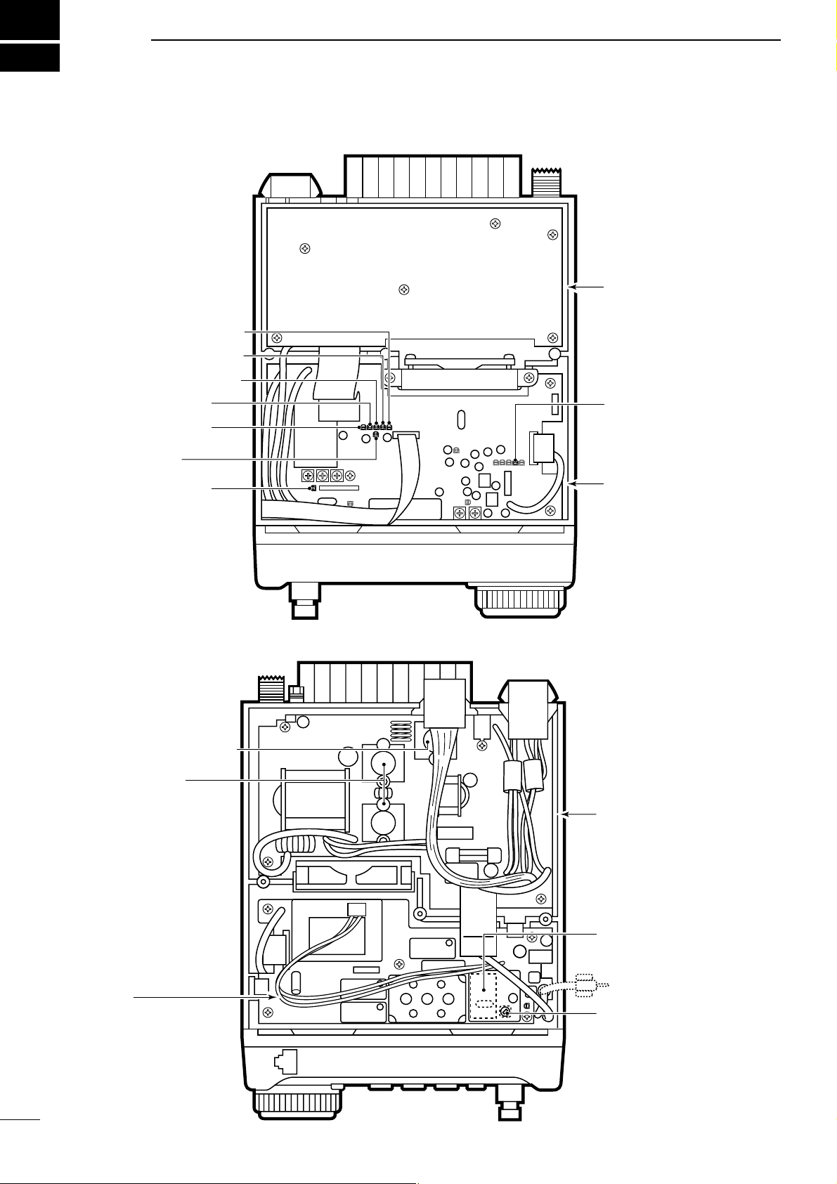
63
11
INTERNAL VIEWS
The internal speaker has
been removed in this
diagram for illustration
purposes.
FM deviation adj.
AM Tx carrier adj.
HF Tx power adj.
50 MHz Tx power adj.
NB sencitivity adj.
ID APC adj.
144 MHz Tx power adj.
430 MHz Tx power adj.
FILTER unit
MAIN unit
PLL unit
HF Final amplifier
(SRFJ7044 x 2)
PA unit
Reference freq. adj. (L601)
(when optional crystal
is installed)
Optional crystal (CR-282)
Reference freq. check point
(60.000 MHz)
144/430 MHz Final amplifier
(SRFJ7044)
D Top view
D Bottom view
Caution:
The transceiver has been
thoroughly tested and
adjusted at the factory
before being shipped. The
transceiver warranty does
not cover any problems
caused by unauthorized
internal adjustment.
Page 67

64
12
OPTIONS
IC-PW1 HF + 50 MHz 1 kW LINEAR AMPLIFIER
Full-duty 1 kW linear amplifier
including an automatic antenna
tuner. Has automatic tuning and
band selection capability. Full
break-in (QSK) operation is possible. The amplifier/power supply
unit and the remote control unit
are separated. The OPC-599 is
necessary to connect the IC706MKIIG to the IC-PW1.
AT-180 HF/50 MHz AUTOMATIC
ANTENNA TUNER
Fully automatic antenna tuner with preset
memories for each 100 kHz. Unique “automatic tuner on” function is available. See
p. 62 for AT-180 specifications.
HM-118T HAND MICROPHONE
Includes DTMF keypad, hand microphone.
SM-20 DESKTOP MICROPHONE
Includes [UP]/[DOWN] switches and a low
cut function. The OPC-589 is necessary to
use this microphone.
MB-65 MOUNTING BASE
Allows you to conveniently vehicle-mount
the front panel of the IC-706MKIIG. An
MB-63 must be used in combination with
the MB-65.
AH-2b ANTENNA ELEMENT
A 2.5 m long antenna
element for mobile
operation with the
AH-3.
• Frequency
coverage
3.5–28 MHz band
with the AH-3
SM-8 DESKTOP MICROPHONE
Including 2 connection cables for simultaneous connection of 2 transceivers. Has
[UP]/[DOWN] switches. The OPC-589 is
necessary to use this microphone.
MB-63 MOUNTING BRACKET
Metal plate for attaching the front panel to
a wall or other such flat surface.
AH-4 HF AUTOMATIC ANTENNA
TUNER
Specially designed to tune a long wire
antenna for portable or mobile HF/50 MHz
operation. The “PTT tune” function provides simple operation.
• Input power rating: 150 W
PS-85 DC POWER SUPPLY
Light weight switching regulator system
power supply.
• Output voltage: 13.8 V DC
• Max. current drain: 20 A
MB-62 MOBILE MOUNTING
BRACKET
Mounts the transceiver main body, with or
without the front panel, inside a vehicle.
Page 68

65
12
OPTIONS
CR-282 HIGH-STABILITY CRYSTAL UNIT
Contains a temperature-compensating oven heater and crystal unit
for frequency stability.
• Frequency stability: ±0.5 ppm (–10°C to +60°C; +14°F to +140°F)
FL-100 CW NARROW FILTER (500 Hz/–6 dB)
FL-101 CW NARROW FILTER (250 Hz/–6 dB)
FL-103 SSB WIDE FILTER (2.8 kHz/–6 dB)
FL-223 SSB NARROW FILTER (1.9 kHz/–6 dB)
FL-232 CW/RTTY NARROW FILTER (350 Hz/–6 dB)
Two of the above 5 filters can be installed at one time.
HM-103 HAND MICROPHONE
Standard hand microphone.
OPC-599 ADAPTER CABLE
13-pin, ACC connector to 7-pin + 8-pin ACC connector.
OPC-742 ACC 13-PIN CABLE
Required when using both the AT-180 and a 2 m linear
amplifier.
MB-72 CARRYING HANDLE
Convenient when carrying the transceiver.
UT-102 VOICE SYNTHESIZER UNIT
UT-106 DSP RECEIVE UNIT
SP-21 EXTERNAL SPEAKER
External speaker designed for base station
operation.
• Input impedance: 8 Ω
• Max. input power: 5 W
OPC-581 SEPARATION CABLE
OPC-587 SEPARATION CABLE
Provide front panel detached operation for
mobile installations or compact transceiver
operation.
• OPC-581: 3.5 m (11.5 ft)
• OPC-587: 5 m (16.4 ft)
SP-10 EXTERNAL SPEAKER
SP-12 EXTERNAL SPEAKER
External speakers suitable for mobile operation.
SP-12: Slim-type; 8 Ω/3 W
SP-10: Compact-type; 4 Ω/5 W
CT-17 CI-V LEVEL CONVERTER
UNIT
For remote transceiver control using a personal computer equipped with an RS-232C
port. You can change frequencies, operating mode, memory channels, etc., via your
computer.
SP-7 EXTERNAL SPEAKER
Compact speaker for base station operation. Height can be adjusted for your convenience.
• Input impedance: 8 Ω
• Max. input power: 5 W
CT-16 SATELLITE INTERFACE
UNIT
Easy tuning when connecting another Icom
VHF transceiver for instant satellite communications.
OPC-589 MICROPHONE ADAPTER
CABLE
Conversion between 8-pin modular and 8pin metal connector for using a desktop
microphone with the IC-706MKIIG.
SP-20 EXTERNAL SPEAKER
Equipped with 4 types of audio filters, a
headphone jack and can be connected to 2
transceivers.
• Input impedance: 8 Ω
• Max. input power: 5 W
SP-12 SP-10
PS-125 DC POWER SUPPLY
Light weight switching regulator system
power supply.
• Output voltage: 13.8 V DC
• Max. current drain: 25 A
Page 69

66
13
SPECIFICATIONS
■ GENERAL
• Frequency coverage : Receive
30 kHz– 199.999999 MHz*
400–470.000 MHz*
Transmit
1.800– 1.99999 MHz*
3.500– 3.9999 MHz*
7.000– 7.300 MHz*
10.100– 10.150 MHz
14.000– 14.350 MHz
18.068– 18.168 MHz
21.000– 21.450 MHz
24.890– 24.990 MHz
28.000– 29.700 MHz
50.000– 54.000 MHz*
144.000– 148.000 MHz*
430.000– 450.000 MHz*
*Depending on version.
• Mode : SSB, CW, AM, FM, WFM, RTTY
(WFM is for receive only)
• Number of memory : 107 (split memory: 99; scan edges: 6;
channels call channels: 2)
• Antenna connector : SO-239 × 2 (for HF/50 MHz and
144/430 MHz)/50 Ω
• Usable temperature : –10°C to +60°C (+14°F to +140°F)
range
• Frequency stability : Less than ±7 ppm from 1 min. to
60 min. after power ON. After that,
rate of stability change is less than
±1 ppm/hr. at +25°C (+77°F).
Temperature fluctuations (0°C to
+50°C; +32°F to +122°F) less than
± 5 ppm.
• Power supply : 13.8 V DC ±15% (negative ground)
requirement
• Current drain : Transmit 20 A
(at 13.8 V DC) Receive squelched 1.8 A
max. audio 2.0 A
• Dimensions : 167(W)
× 58(H) × 200(D) mm
6
9
⁄16(W) × 25⁄16(H) × 77⁄8(D) in
(projections not included)
• Weight : 2.45 kg (5 lb 6 oz)
• CI-V connector : 2-conductor 3.5 (d) mm (
1
⁄8˝)/8 Ω
• ACC connector : 13-pin
■ TRANSMITTER
• Output power :
SSB, CW, FM, RTTY 5 –100 W
(1.8–50 MHz bands)
5–50 W (144 MHz band)
2–20 W (430 band)
AM 2–40 W (1.8–50 MHz bands)
2–20 W (144 MHz band)
2–8 (430 band)
• Modulation system :
SSB Balanced modulation
AM Low level modulation
FM Variable reactance modulation
• Spurious emissions : Less than – 60 dB*
*spurious freq.: below 30 MHz: –50 dB (typ.); above 50 MHz: –60
dB (typ.).
• Carrier suppression : More than 40 dB
• Unwanted sideband : More than 50 dB
• Microphone : 8-pin modular jack (600 Ω)
connector
• KEY connector : 3-conductor 6.35 (d) mm (
1
⁄4")
• RTTY connector : 3-conductor 3.5 (d) mm (
1
⁄8")
■ RECEIVER
• Receive system :
SSB, CW, AM, RTTY Double-conversion superheterodyne
WFM
FM Triple-conversion superheterodyne
• Intermediate frequencies:
• Sensitivity
(pre-amp ON):
• Squelch sensitivity
(threshold; preamp ON) :
SSB Less than 5.6 µV
FM Less than 0.3 µV
• Selectivity* :
SSB, CW, RTTY More than 3.0 kHz/–6 dB
Less than 4.8 kHz/–60 dB
AM/FM-N More than 8.0 kHz/–6 dB
Less than 30.0 kHz/–40 dB
FM More than 12.0 kHz/–6 dB
Less than 30.0 kHz/–60 dB
*Without optional filter and with
mid band selected.
• Spurious and image rejection ratio:
HF More than 70 dB
50 MHz More than 65 dB
(except IF through)
144/430 MHz More than 65 dB
• Audio output power : More than 2.0 W
at 10% distortion
with an 8 Ω load
• RIT variable range : ±9.99 kHz max.
• PHONES connector : 3-conductor 3.5 (d) mm (
1
⁄8˝)/8 Ω
• EXT SP connector : 2-conductor 3.5 (d) mm (
1
⁄8˝)/8 Ω
MODE 1st 2nd 3rd
SSB 69.0115 MHz 9.0115 MHz
—
AM 69.0100 MHz 9.0100 MHz
—
AM-N 69.0115 MHz 9.0115 MHz
—
RTTY 69.0105 MHz 9.0105 MHz
—
FM 69.0115 MHz 9.0115 MHz 455 kHz
FM-N 69.0100 MHz 9.0100 MHz 455 kHz
WFM 70.7000 MHz 10.7000 MHz
—
CW 69.0106 MHz 9.0106 MHz
—
Frequency
range
SSB/CW
10 dB S/NAM10 dB S/NFM12 dB SINAD
WFM
12 dB SINAD
0.5–1.8 MHz — 13 µV — —
1.8–28 MHz
0.15 µV 2.0 µV
— —
28–29.7 MHz
0.5 µV —
50 MHz band 0.12 µV 1.0 µV 0.25 µV —
76–108 MHz — — — 10.0 µV
144/430 MHz
bands
0.11 µV 1.0 µV 0.18 µV —
Page 70

67
14
MENU GUIDE
Initial set mode
No. Indication Description
1 MODE SELECT
2 BEEP
3 BAND BEEP
4 BACK LIGHT
5 KEY LIGHT
6 AUTO OFF
7 RF/SQL
8 SUB DIAL
9 OPT.FIL 1
10 OPT.FIL 2
11 PEAK HOLD
12
QUICK SPLIT
Mode availability
Confirmation beeps
Band edge beeps
Display backlighting
Key backlighting
Auto power OFF function
RF gain/squelch control
Sub dial RIT function
Speech synthesizer lang.
Speech synthesizer speed
Speech synthesizer S-meter
Meter peak function
[UP]/[DN] speed
Auto tune start function
No. Indication Description
13 SPLIT LOCK
PTT tune function
14 SPL OFFSET
15 DUP HF
16 DUP 50M
17 DUP 144M
18 DUP 430M
19 1TOUCH RPTR
No. of memory pads
20 AUTO RPTR
21 SCAN RESUME
22 SCAN SPEED
23 U/D SPEED
24 AM NB
25 PAD CH
26 PWR ON CHK
27 A-TUNE STRT
28
VSEND SEL
29
SPEECH LANG
30
SPEECH SPD
31
32
33
S-LVL SPC
34
CI-V ADDRES
35
CI-V BAUD
36
CI-V TRN
37
CI-V 731
Quick split function
Split lock function
Quick split offset
Quick split offset
(HF)
Quick split offset (50 MHz)
Quick split offset
(144 MHz)
Quick split offset (430 MHz)
One touch repeater
Scanning speed
Auto repeater function
Scan resume condition
Optional filter 1
Optional filter 2
Power ON check function
AM noise blanker
PTT TUNE
9600 MODE
Packet data speed
ACC output selection
CI-V address assignment
Data transfer rate
CI-V transceive
CI-V 731
+ power ON
Power OFF then ON to exit initial set mode.
MENU
MENU
Y
Z
LOCK
Page 71

68
14
MENU GUIDE
M1 SPL A/B
XFC
A=B
M2 MW MÜV
MCL
V/M
M3 FIL NB MET
M4 VOX COM AGC
VOXM4 COM TON
1/4
1/4
M4 AGC
BRKM4 AGC
S1 MW MPW MPR
S2 SCN PRI
SEL
V/M
Quick set mode
For 2 sec.
MENU
MENU
(SSB/AM)
(when split
is ON)
(in memory
mode)
(in memory mode)
(CW)
(RTTY)
(FM)
S3 7 50 144
S4 ANF NR NRL
G1 BAND scope
G2 IF SHIFT
G3 TX freq.
G4 Memory name
DISPLAY
DISPLAY
DISPLAYDISPLAY
MENU
MENU
Y
Y
M-CH
No.
Q1 RF POWER RF POWER RF POWER
Q2 MIC GAIN CW PITCH
RTTY TONE
Q3 VOX DELAY
VOX GAIN
BK-IN DELAY RTTY SHIFT
Q6
RATIO
Q7
Q4
CARRIER Freq*
1
CW PADDLE RTTY KEYING
SSB/AM/FM mode
RPTR TONE*
2
TONE SQL*
2
CW mode RTTY mode
Q8
RPTR-T*
3
T-SQL*
4
Q5 KEY SPEED
ANTI VOX
*
1
SSB mode only; *2FM mode only; *3FM mode only/tone encoder ON;
*
4
FM mode only/tone squelch ON.
MODE
DISPLAY
Page 72

A-5564H-1EX-r
Printed in Japan
Copyright © 2001 by Icom Inc.
1-1-32 Kamiminami, Hirano-ku, Osaka 547-0003, Japan
Count on us!
Page 73

ABOUT CE
•Version and frequency coverage
Europe (#02, #12)
Tx 1.800000 – 1.850000
3.500000– 3.800000
7.000000– 7.100000
10.100000– 10.150000
14.000000– 14.350000
18.068000– 18.168000
21.000000– 21.450000
24.890000– 24.990000
28.000000– 29.700000
50.000000– 52.000000
144.000000– 146.000000
430.000000– 440.000000
Rx 0.030000– 29.999999
50.000000– 52.000000
144.000000– 146.000000
430.000000– 440.000000
Spain (#04,#14)
Tx 1.830000 – 1.850000
3.500000– 3.800000
7.000000– 7.100000
10.100000– 10.150000
14.000000– 14.350000
18.068000– 18.168000
21.000000– 21.450000
24.890000– 24.990000
28.000000– 29.700000
50.000000– 50.200000
144.000000– 146.000000
430.000000– 440.000000
Rx 1.830000– 1.850000
3.500000– 3.800000
7.000000– 7.100000
10.100000– 10.150000
14.000000– 14.350000
18.068000– 18.168000
21.000000– 21.450000
24.890000– 24.990000
28.000000– 29.700000
50.000000– 50.200000
144.000000– 146.000000
430.000000– 440.000000
France (#03,#13)
Tx 1.810000 – 1.850000
3.500000– 3.800000
7.000000– 7.100000
10.100000– 10.150000
14.000000– 14.350000
18.068000– 18.168000
21.000000– 21.450000
24.890000– 24.990000
28.000000– 29.700000
50.200000– 51.200000
144.000000– 146.000000
430.000000– 440.000000
Rx 1.810000– 1.850000
3.500000– 3.800000
7.000000– 7.100000
10.100000– 10.150000
14.000000– 14.350000
18.068000– 18.168000
21.000000– 21.450000
24.890000– 24.990000
28.000000– 29.700000
50.200000– 51.200000
144.000000– 146.000000
430.000000– 440.000000
Italy (#10,#20)
Tx 1.830000 – 1.850000
3.500000– 3.800000
7.000000– 7.100000
10.100000– 10.150000
14.000000– 14.350000
18.068000– 18.168000
21.000000– 21.450000
24.890000– 24.990000
28.000000– 29.700000
50.000000– 51.000000
144.000000– 146.000000
430.000000– 434.000000
435.000000– 438.000000
Rx 1.830000– 1.850000
3.500000– 3.800000
7.000000– 7.100000
10.100000– 10.150000
14.000000– 14.350000
18.068000– 18.168000
21.000000– 21.450000
24.890000– 24.990000
28.000000– 29.700000
50.000000– 51.000000
144.000000– 146.000000
430.000000– 434.000000
435.000000– 438.000000
(UNIT: MHz)
DECLARATION
OF CONFORMITY
We Icom Inc. Japan
1-1-32 Kamiminami, Hirano-ku,
Osaka 547-0003 Japan
Kind of equipment: HF/
VHF/UHF ALL MODE TRANSCEIVER
This compliance is based on conformity according to Annex III of the
RTTE Directive 1999/5/EC using the following harmonised standards:
i) Article 3.1a
EN 60950 + A11
ii) Article 3.1b EN 301489-1 and EN 301489-15
iii) Article 3.2 EN 301 783-2
iv)
v)
Type-designation: i706MKIIG
Signature
Authorized representative name
Place and date of issue
T. Aoki
General Manager
Icom (Europe) GmbH
Himmelgeister straße 100
D-40225 Düsseldorf
Düsseldorf 13th Mar. 2001
Icom (Europe) GmbH
Declare on our sole responsibility that this equipment complies with the
essential requirements of the Radio and Telecommunications Terminal
Equipment Directive, 1999/5/CE, and that any applicable Essential Test
Suite measurements have been performed.
Version (where applicable):
•About DC power supply.
The use of IC-706MKIIG (#02, #12, #03, #13, #04, #14,
#10, #20) in combination with The DC power supply complies with European Harmonised Standard regulations
under the conditions listed below.
Conditions
•In combination with PS-125
•When connected to a power supply via OPC-639
•
About IC-PW1
LINEAR AMPLIFIER
and SP-10,
SP-12, SP-20, SP-21
EXTERNAL SPEAKERS
.
The IC-PW1
LINEAR AMPLIFIER
and The SP-10, SP-12, SP-
20, SP-21
EXTERNAL SPEAKERS
do not comply with European Harmonised Standard regulations. Please do not use
these equipments within European countries.
Page 74

INSTALLATION NOTES
For amateur base station installations it is recommended that the forwards clearance in front of the antenna array is calculated relative to the EIRP (Effective
Isotropic Radiated Power). The clearance height below
the antenna array can be determined in most cases
from the RF power at the antenna input terminals.
As different exposure limits have been recommended
for different frequencies, a relative table shows a
guideline for installation considerations.
Below 30 MHz, the recommended limits are specified
in terms of V/m or A/m fields as they are likely to fall
within the near-field region. Similarly, the antennae
may be physically short in terms of electrical length
and that the installation will require some antenna
matching device which can create local, high intensity
magnetic fields. Analysis of such MF installations is
best considered in association with published guidance
notes such as the FCC OET Bulletin 65 Edition 97-01
and its annexes relative to amateur transmitter installations. The EC recommended limits are almost identical to the FCC specified ‘uncontrolled’ limits and tables
exist that show pre-calculated safe distances for different antenna types for different frequency bands. Further information can be found at http://www.arrl.org/.
•Typical amateur radio installation
Exposure distance assumes that the predominant radiation pattern is forwards and that radiation vertically
downwards is at unity gain (sidelobe suppression is
equal to main lobe gain). This is true of almost every
gain antenna today . Exposed persons are assumed to
be beneath the antenna array and have a typical
height to 1.8 m.
The figures assume the worst case emission of constant carrier.
For the bands 10 MHz and higher the following power
density limits have been recommended:
10 – 400 MHz 2 W/sq m
435 MHz 2.2 W/sq m
EIRP Clearance heights by frequency band
Watts 10–2 m 70 cm 23 cm 13cm and above
1 2.1 m 2 m 2 m 2 m
10 2.8 m 2.7 m 2.5 m 2.3 m
25 3.4 m 3.3 m 2.7 m 2.5 m
100 5 m 4.7 m 3.6 m 3.2 m
1000 12 m 11.5 m 7.3 m 6.3 m
Forward clearance, EIRP by frequency band
Watts 10–2 m 70 cm 23 cm 13cm and above
100 2 m 2 m 1.1 m 0.7 m
1000 6.5 m 6 m 3.5 m 3 m
10,000 20 m 18 m 11 m 7 m
100,000 65 m 60 m 35 m 29 m
In all cases any possible risk depends on the transmitter being activated for long periods. (actual recommendation limits are specified as an average during 6
minutes) Normally the transmitter is not active for long
periods of time. Some radio licenses will require that a
timer circuit automatically cuts the transmitter after 1–2
minutes etc.
Similarly some types of transmitter, SSB, CW, AM etc.
have a lower ‘average’ output power and the assessed
risk is even lower.
Versions of the IC-706MKIIG which display the
“CE” symbol on the serial number seal, comply
with the essential requirements of the European
Radio and Telecommunication Terminal Direc tive 1999/5/EC.
This warning symbol indicates that this equipment operates in non-harmonised frequency
bands and/or may be subject to licensing conditions in the country of use. Be sure to check
that you have the correct version of this radio or
the correct programming of this radio, to comply with national licensing requirement.
GER
AUT
GBR
IRL
FRA
NED
BEL
LUX
ESP
POR
ITA
GRE
SWE
DEN
FIN
< Intended Country of Use >
GER
AUT
GBR
IRL
FRA
NED
BEL
LUX
ESP
POR
ITA
GRE
SWE
DEN
FIN
< Intended Country of Use >
IC-706MKIIG
#02, #12
(Europe)
IC-706MKIIG
#04 ,#14
(Spain)
GER
AUT
GBR
IRL
FRA
NED
BEL
LUX
ESP
POR
ITA
GRE
SWE
DEN
FIN
< Intended Country of Use >
GER
AUT
GBR
IRL
FRA
NED
BEL
LUX
ESP
POR
ITA
GRE
SWE
DEN
FIN
< Intended Country of Use >
IC-706MKIIG
#03, #13
(France)
IC-706MKIIG
#10, #20
(Italy)
1-1-32 Kamiminami, Hirano-ku, Osaka 547-0003 Japan
Count on us!
A-6045H-1EU Printed in Japan
© 2001 Icom Inc.
Page 75

ABOUT SP-7 EXTERNAL SPEAKER
Cable fastener
pull
If the SP-7 external speaker is used with the IC-706MKIIG, please install the ferrite supplied bead on the speaker cable, as shown below.
• A ferrite bead and a cable fastener are supplied with IC-706MKIIG.
INSTALLATION NOTE:
• Install the ferrite bead as near as possible the connecting plug.
• Attach the ferrite bead making a loop with the cable as shown in the diagram at
below left.
• Fasten the ferrite bead and speaker cable with the supplied cable fastener.
1-1-32 Kamiminami, Hirano-ku, Osaka 547-0003 Japan
Count on us!
A-6045H-2EU Printed in Japan
© 2001 Icom Inc.
 Loading...