

o ICOM
INSTRUCTION MANUAL

This device complies with Part 15 of the FCC rules. Operation is subject to the following two conditions: (1) This device may not cause harmful interference, and (2) this device must accept any interference received, including interference that may cause undesired operation.
Icom Inc.
IMPORTANT
Read this instruction manual carefully before attempting to operate the transceiver.
Save this instruction manual. This instruction manual contains important safety and operating instructions for the IC-706MKII.
PRECAUTIONS
A WARNING HIGH VOLTAGE! NEVER attach an antenna or internal antenna connector during transmission. This may result in an electrical shock or burn.
ANEVER apply AC to the [DC13.8V] socket on the transceiver rear panel. This could cause a fire or ruin the transceiver.
ANEVER apply more than 16 V DC, such as a 24 V battery, to the [DC13.8V] socket on the transceiver rear panel. This could cause a fire or ruin the transceiver.
ANEVER let metal, wire or other objects touch any internal part or connectors on the rear panel of the transceiver. This will cause electric shock.
NEVER expose the transceiver to rain, snow or any liquids.
NEVER allow children to play with the transceiver.
AVOID using or placing the transceiver in areas with temperatures below -10°C (+14°F) or above +60°C (+140°F). Be aware that temperatures on a vehicle's dashboard can exceed 80°C, resulting in permanent damage to the transceiver's front panel if left there for extended periods.
AVOID placing the transceiver in excessively dusty environments or in direct sunlight.
AVOID placing the transceiver against walls or putting anything on top of the transceiver. This will obstruct heat dissipation.
During mobile operation, DO NOT operate the transceiver without running the vehicle's engine. When transceiver power is ON and your vehicle's engine is OFF, the vehicle's battery will soon become exhausted.
Make sure the transceiver power is OFF before starting the vehicle. This will avoid possible damage to the transceiver by ignition voltage spikes.
During maritime mobile operation, keep the transceiver and microphone as far away as possible from the magnetic navigation compass to prevent erroneous indications.
BE CAREFUL! The heatsink will become hot when operating the transceiver continuously for long periods.
BE CAREFUL! If a linear amplifier is connected, set the transceiver's RF output power to less than the linear amplifier's maximum input level, otherwise, the linear amplifier will be damaged.
Use Icom microphones only (supplied or optional). Other manufacturer's microphones have different pin assignments and connection to the IC-706MKII may damage the transceiver.
Beat signals may be heard on some frequencies. These will occur as a result of circuit construction.
For U.S.A. only
Caution: Changes or modifications to this transceiver, not expressly approved by Icom Inc., could void your authority to operate this transceiver under FCC regulations.
EXPLICIT DEFINITIONS
The explicit definitions described below apply to this instruction manual.
| WORD | DEFINITION |
|---|---|
| Personal injury, fire hazard or electric shock may occur. | |
| CAUTION | Equipment damage may occur. |
| NOTE | If disregarded, inconvenience only. No risk of personal injury, fire or electric shock. |
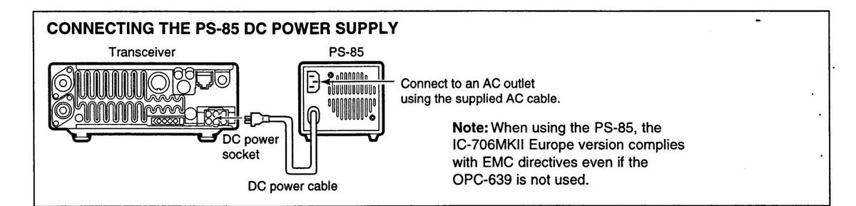
The IC-706MKII Europe version complies with essential requirements of the 89/336/EEC directive for Electromagnetic Compatibility under the conditions listed below. This compliance is based on conformity with the ETSI specification ETS300 684 Jan. 1997 (EMC product standard for Commercially Available Amateur Radio Equipment).
Condition: •In combination with PS-85 •When connected to a power supply via OPC-639
TABLE OF CONTENTS
|
IMPORTANT
PRECAUTIONS EXPLICIT DEFINITIONS TABLE OF CONTENTS UNPACKING |
i |
|---|---|
|
1 PANEL DESCRIPTION
Front panel Function switches Rear and side panels Function display Microphone (HM-103) |
1–8
1 |
|
2 INSTALLATION AND CONNECTIONS
Unpacking Grounding Antenna Installation Required connections Advanced connections Power supply connections External antenna tuners and linear amplifier |
914
9 9 |
|
15–19
18 18 16 17 19 |
|
4 RECEIVE AND TRANSMIT
Functions for receive Functions for transmit Split frequency operation Tone squelch operation Functions for CW Functions for RTTY |
20–3!
20 |
|
5 MEMORY AND SCAN OPERATION
Memory channels Memory channel selection |
36–4
36 |
| 36 | ||
| Memory/call programming | 37 | |
| Frequency transferring | 38 | |
| Memory names | 38 | |
| Memo pads | 39 | |
| Scan types | 40 | |
| Preparation | ••••• | 40 |
| Programmed scan operation | 41 | |
| Memory scan operation | 41 | |
| Select memory scan operation | ••••• | 41 |
| Priority watch | 41 | |
| 6 REMOTE JACK (CI-V) INFORMATION | ••••• | 42 |
| 7 SET MODE | 43 | 49 |
| General | 43 | |
| ■Quick set mode items | 44 | |
| ■Initial set mode items | 46 | |
| 50 | ||
| ■ Fuse replacement | -50 | |
|
50
50 |
|
|
50
50 50 |
|
|
51– |
50
50 50 50 |
|
51-
53- |
50
50 50 • 52 |
| Puse replacement Memory backup Cleaning 9 TROUBLESHOOTING 10 OPTIONAL INSTALLATIONS/SETTINGS . Opening the transceiver case |
51–
53– |
50
50 50 • 52 • 56 53 |
|
51–
53– |
50
50 50 50 53 53 |
|
51–
53– |
50
50 50 • 52 53 53 53 |
|
51–
53– |
50
50 50 • 52 53 53 54 54 |
|
51–
53– |
50
50 50 50 53 53 53 54 54 54 55 |
|
51–
53– |
50
50 50 52 53 53 53 54 54 55 56 |
|
51 |
50
50 50 52 53 53 53 54 54 55 56 56 57 |
|
51–
53– 53– |
50
50 50 52 53 53 53 54 55 54 55 56 57 57 |
|
51-
53- 58- |
50
50 50 52 53 53 54 54 55 56 57 57 60 |
UNPACKING
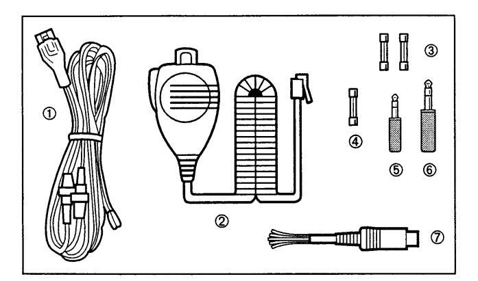
Accessories included with the IC-706MKII:
| ωιγ. | |
|---|---|
| ① DC power cable* | 1 |
| 2 Hand microphone (HM-103) | 1 |
| ③ Spare fuse (30 A) | 2 |
| ④ Spare fuse (4 A) | 1 |
| 5 RTTY key plug | 1 |
| 6 Electronic keyer plug | 1 |
| ⑦ ACC cable | 1 |
| *OPC-639 for Europe versions (differs from the di | agram at |
| left) OPC-025D for other versions |
PANEL DESCRIPTION
Front panel
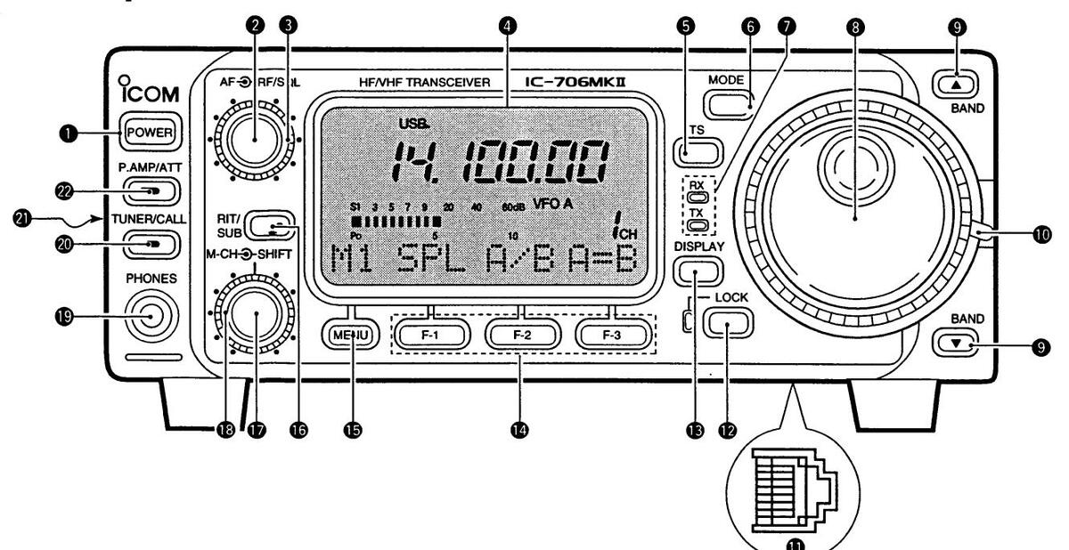
• POWER SWITCH [POWER] (p. 15)
Turns power ON and OFF. •Push momentarily to turn power ON. •Push for 2 sec. to turn power OFF.
2 AF GAIN CONTROL [AF] (inner control; p. 15)
Rotate clockwise to increase the audio output from the speaker; rotate counterclockwise to decrease the audio output from the speaker.
G RF GAIN CONTROL/SQUELCH CONTROL
[RF/SQL] (outer control; p. 22)
- Adjusts the squelch threshold level (to mute noise when receiving no signal) in all modes.
-
This control can be used for RF gain control to adjust receiver gain manually.
- •RF gain selection can be set in initial set mode (p. 47). •RF gain is usable in SSB/CW/RTTY modes only.
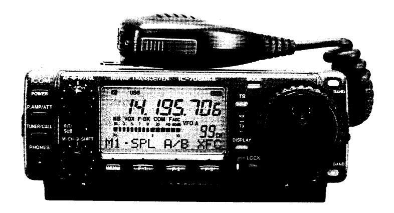
4 FUNCTION DISPLAY
Shows the operating frequency, dot matrix indications, selected memory channel, etc. See p. 7 for details.
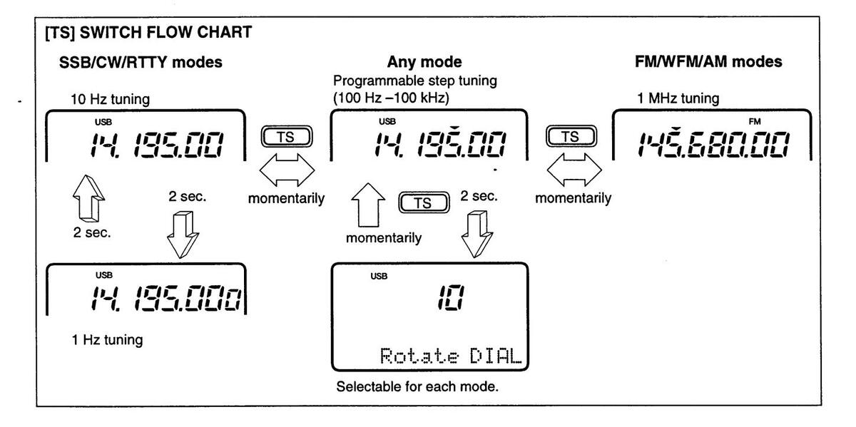
GTUNING STEP SWITCH [TS] (pgs. 17, 18)
-
Push momentarily to cycle between 1 Hz/10 Hz, programmable and 1 MHz tuning steps.
- •1 and 10 Hz steps are only available in SSB, CW and RTTY modes; 1 MHz steps are only available in FM, WFM and AM modes.
- Push for 2 sec. to toggle between 1 and 10 Hz steps, or; when the programmable tuning steps is indicated, push for 2 sec. to enter programmable tuning step mode.
G MODE SWITCH [MODE] (p. 19)
Push momentarily to cycle through the operating modes:
USB/LSB CW/CWE RTTY/ERTTY
-
Push and hold for 2 sec. to toggle between the following operating modes:
- USB ↔ LSB
- RTTY↔ ⊡ RTTY
- FM → WFM → AM → FM, etc.
@ RECEIVE/TRANSMIT INDICATORS [RX]/[TX]
[RX] lights green while receiving (and squelch opens); [TX] lights red while transmitting.
MAIN DIAL
Changes the displayed frequency, selects initial set mode items, etc.
③ UP/DOWN (BAND) SWITCHES [▲/▼(BAND)]
-
Push to select a band.
- •Can also be used to advance quick set mode items, initial set mode items, etc.
- Push and hold to scroll through the bands continuously.
MAIN DIAL TENSION LATCH
Selects the main dial tension. •2 positions are available.
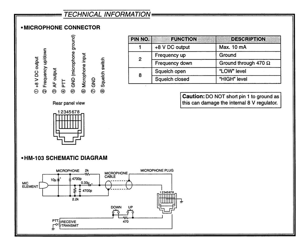
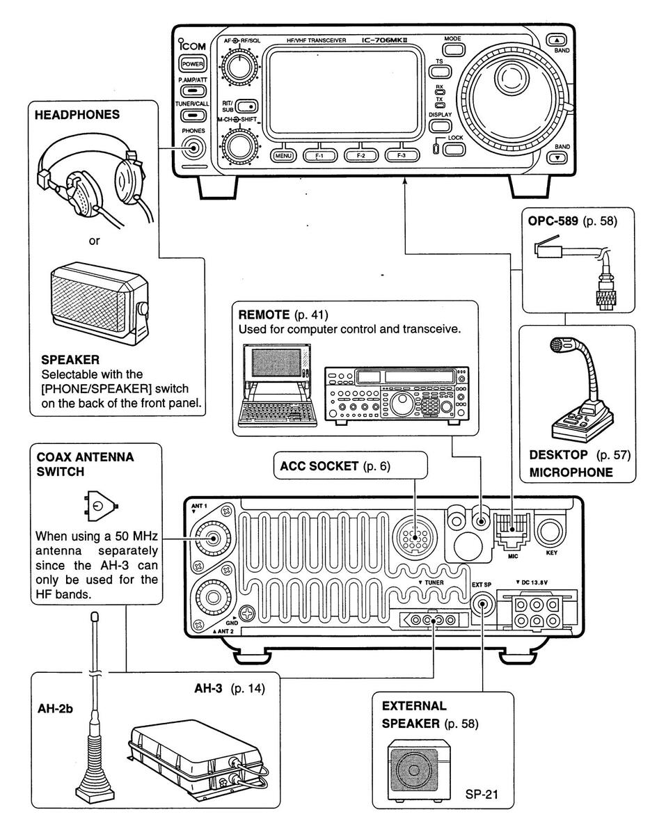
MICROPHONE CONNECTOR (p. 8)
Modular-type microphone connector—connects the supplied microphone (HM-103).
- •The optional OPC-589 can be used to connect an 8-pin microphone such as the SM-8 or SM-20, if desired.
- •A microphone connector is also available on the rear
panel. DO NOT connect 2 microphones simultaneously.
(DLOCK SWITCH [LOCK]
➡ Push momentarily to turn the dial lock function ON and OFF.
•The dial lock function electronically locks the main dial.
-
→ When the optional UT-102 VOICE SYNTHESIZER UNIT is installed (p. 52), push for 2 sec. to have the frequency, etc. announced.
- •UT-102 operation can be adjusted in initial set mode (pgs. 45, 46).
BDISPLAY SWITCH [DISP] (p. 60)
- ➡ Push momentarily to select one of the three menu sets: M1 to M4, S1 to S3 and G1 to G4.
- ➡ Push for 2 sec. to select quick set mode.
( FUNCTION SWITCHES [F1]/[F2]/[F3] (pgs. 3, 4, 60)
Push to select the function indicated in the dot matrix display above these switches.
• Functions vary depending on the menu set selected.
(p. 60)
- ➡ Push this switch one or more times to select menus within a menu set (□, 5 or 5), or push to advance through the quick set mode and initial set mode displays.
- ➡ Push and hold to jump between two different function menu sets.
M-CH CONTROL [M-CH] (inner control)
- ➡ When the RIT or SUBDIAL functions are OFF, rotate to select a memory channel number (p. 35).
- Shifts the receive frequency while the RIT function is ON in SSB, CW and RTTY modes (see below and p. 20).
•RIT variable range is ± 9.99 kHz
Changes the operating frequency in the selected tuning steps while the SUB DIAL function is ON (p. 18).
W SHIFT CONTROL [SHIFT] (outer control; p. 20)
Shifts the center frequency of the receiver's IF passband.
• Rotate the control clockwise to shift the center frequency higher, or rotate the control counterclockwise to shift the center frequency lower.
•When the graphic menu display (G2) is selected, the IF passband is graphically displayed and changes in accordance with the [SHIFT] control (see p. 20).
BRIT/SUB DIAL SWITCH [RIT/SUB] (p. 20)
-
Push to toggle the RIT or SUB DIAL function ON and OFF—initial set mode is used to select the desired action*.
- •Lights green when the SUB DIAL function is ON; lights red when the RIT function is ON.
- •Use the [M-CH] control to vary the RIT frequency or SUB DIAL frequency (see above).
- When the RIT function is ON, push for 2 sec. to add or subtract the shifted frequency to the operating frequency.
Lights red while the RIT function is activated; green while the SUB DIAL function is activated.
*Even if RIT is selected in initial set mode, RIT cannot be selected when operating AM, FM or WFM modes.
(p. 12) (p. 12)
Accepts headphones with 4-16 Ω impedance.
•When headphones are connected, no receive audio •comes from the speaker.
•When the PHONES/SPEAKER switch on the back of the front panel is set to the [SPEAKER] position, an external speaker can be connected. This is convenient for mobile or outdoor operation.
@TUNER/CALL SWITCH [TUNER/CALL]
(pgs. 26, 27)
During HF/50 MHz operation, push this switch momentarily to toggle the automatic antenna tuner function ON/OFF.
•An optional antenna tuner must be connected.
- During HF/50 MHz operation, push this switch for 2 sec. to manually tune the antenna. An optional antenna tuner must be connected.
- During 144 MHz operation, push this switch momentarily to select the call channel (or the previous channel/frequency when the call channel is already selected). (p. 35)
Lights while the automatic tuning function is activated
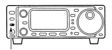
TRONT PANEL LATCH (p. 10)
Pull away from the transceiver (towards yourself when looking at the front of the transceiver) to detach the front panel from the main body of the transceiver.
@ PREAMP/ATTENUATOR SWITCH [P.AMP/ATT]
(p. 21)
- Push momentarily to turn the preamp ON; also turns the attenuator OFF if it is ON.
- Push and hold to turn the 20 dB attenuator ON. Lights green when the preamp is ON; lights red when the 20 dB attenuator is ON.
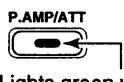
Lights green while the preamp is activated; lights red while the attenuator is activated.
Eunction switches
♦ M1 FUNCTIONS
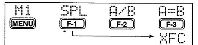
SPLIT OPERATION (p. 28)

Toggles the split function ON and OFF.
•"Sell" appears when the split function is ON • The function of [F-3] changes to XEC when the
split function is ON.
VFO A/B SELECTION (p. 16)
- VEO mode
-
F-2 •
Toggles between transmission VFO and reception VFO during split operation.
- ➡ Toggles between the transmit and receive frequencies (and modes) of memory channels when the split function is turned ON
VEO EQUALIZATION (p. 16)

Equalizes the frequency and operating mode of the two VEO's
•The rear (undisplayed) frequency and operating mode are equalized to the front (displayed) VFO frequency and operating mode.
TRANSMIT FREQUENCY CHECK (p. 28)
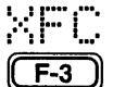
Appears when the split function is turned ON-monitors the transmit frequency
when pushed and held.
•While pushed, the transmit frequency can be changed with the main dial.
♦ M2 FUNCTIONS

MEMORY WRITE (p. 36)

Stores the displayed frequency and operating mode into the displayed memory
MEMORY TRANSFER (p. 37)

Transfers the frequency and operating mode in the selected memory channel to a
VFO/MEMORY (p. 35)
I Toggles between VFO and memory modes.
MEMORY CLEAR (p. 35)

♦ M3 FUNCTIONS
|
HB
F-2 |
||
|---|---|---|
NABBOW FILTER (p. 23)
|
Toggles |
the | narrow | filter | (or | wide | filter- |
|---|---|---|---|---|---|---|
|
nuch for |
2 0 | AL ON | and O | EE |
for 2 sec.) ON and OFF. F-1
•"I" appears when the narrow filter is ON; "I" appears when the wide filter is ON.
An optional narrow filter and presetting in initial set mode (p. 47) is necessary to use the following:
CW/RTTY narrow: El -100, El -101 or El -232 SSB narrow: FL-223 SSB wide: FL-103
NOISE BLANKER (p. 21)
Turns the noise blanker ON and OFF
F-2
•The noise blanker does not function in FM and WFM modes: the "AM Noise blanker" item in initial set mode must be set to ON for the noise blanker to work in AM mode (p. 47).
METER SELECTION (p. 24)
MET
同言
MENU
Selects the type of meter displayed (during transmit) in the function display
•Power, ALC or SWR metering can be selected
•Only an S-meter is available for receive.
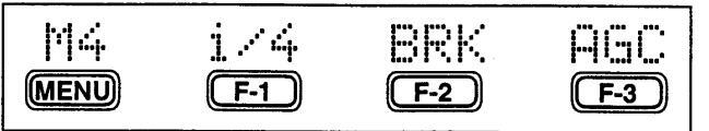
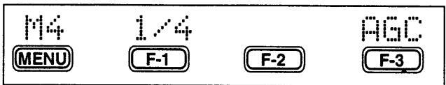
♦ M4 FUNCTIONS
DURING SSB/AM OPERATION:
| F-1 F-2 F-3 | ) |
U());;;
(F-1) |
[].[]|'|
(F-2) |
F-3 |
|---|
DURING CW OPERATION
DURING RTTY OPERATION
DURING EM OPERATION
| 团杀 | ŲOX | TSQ | TON |
|---|---|---|---|
| MENU | F-1 | F-2 | F-3 |
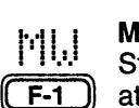
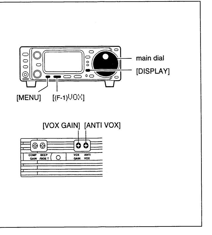
VOX FUNCTION (p. 25)
Toggles the VOX function ON and OFF UNX
•The [VOX GAIN] and [ANTI VOX] are avail- F-1 able on the side panel.
•VOX delay can be set in quick set mode (p. 43).
SPEECH COMPRESSOR (p. 25)
Togales the speech compressor ON and COM F-2
•The [COMP GAIN] control is available on the side panel.
AGC (p. 21) Changes the time constant of the AGC cir-
| AGC |
Cha
cuit. |
|---|---|
| F-3 |
BREAK-IN (p. 31)

• "BK" or "F-BK" appears when selecting semi break-in or full break-in, respectively.
•An external switch, such as a foot switch, is necessary to connect to the ACC socket (pin 3. pin 7 or RTTY SEND-see p. 33) to use no break-in operation.
1/4 FUNCTION (p. 34)
Toggles the 1/4 function ON and OFF.

•When the 1/4 function is ON, a bar appears under the 1/4 indication and fine tuning can be
TONE SQUELCH (p. 30)
used.

Toggles the tone squelch function ON and OFF (an optional UT-86 must be installed
and tone squelch frequency must be selected in Quick Set mode).
•"FM-TSQL" appears when the function is ON.
REPEATER TONE OPERATION (p. 29)

➡ Toggles the subaudible tone encoder for repeater use ON and OFF
•"FM-T" appears when the function is ON.
Transmits a 1750 Hz tone burst when pushed and held during transmission. • Tone frequencies or tone burst can be set in initial set mode (p. 44).
♦ S1 FUNCTIONS
| 51 | 团员 | MPW | MPR |
|---|---|---|---|
| MENU | F-1 | F-2 | F-3 |
MEMORY WRITE (p. 36)
Stores the displayed frequency and operating mode into the displayed memory channel
MEMO PAD WRITE (p. 38) MPI. Stores the displayed frequency and oper-
F-2 ating mode into a memo pad.
MEMO PAD READ (p. 38) Calls up a memo pad.
F-3
♦ S2 FUNCTIONS

♦ S3 FUNCTIONS
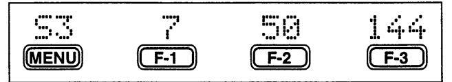
QUICK BAND CHANGE FUNCTION (p. 19)
This item provides access to the band stacking register. By default the 7, 50 and 144 MHz bands are displayed. Push [F-1] to [F-3] for 2 sec. to select a new band if desired.
•A mode is memorized along with the frequency for each band.
PANEL DESCRIPTION
■ Rear and side panels
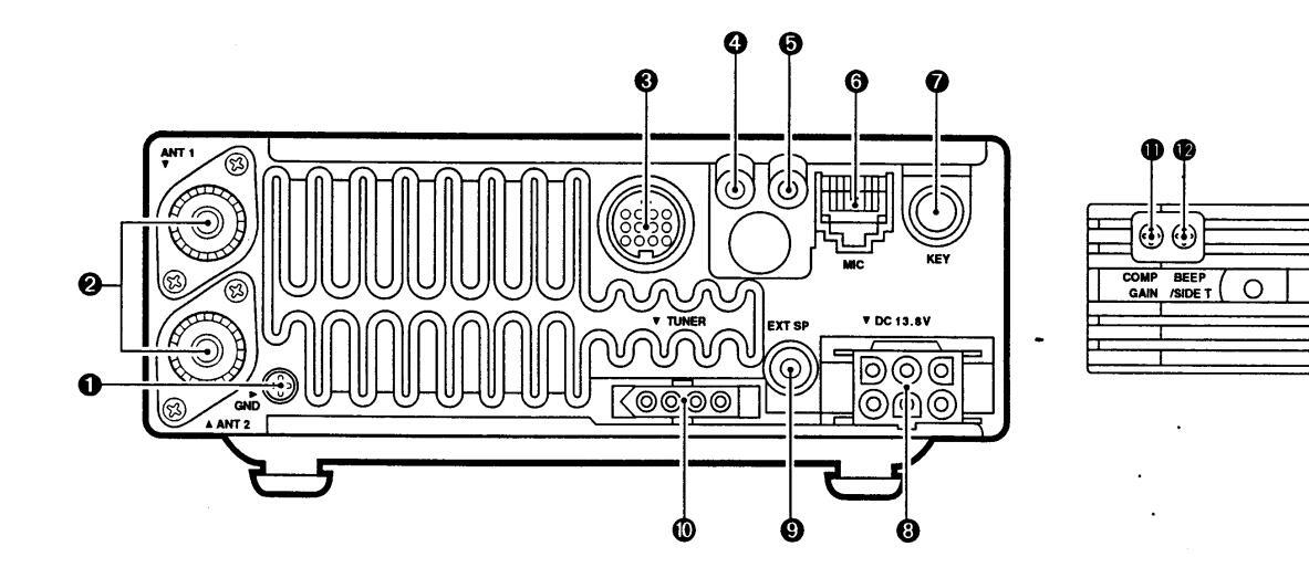

Connect this terminal to a ground to prevent electrical shocks. TVI, BCI and other problems
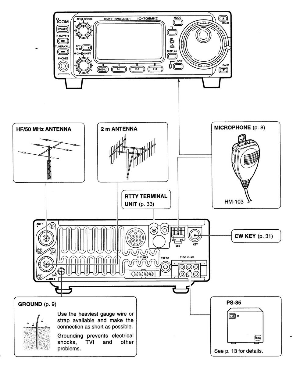
@ANTENNA CONNECTORS [ANT 1], [ANT 2] (p. 11)
Accept a 50 Ω antenna with an PL-259 type plug.
- •[ANT 1] is for connection to an HF/50 MHz antenna.
- •[ANT 2] is for connection to 144 MHz antenna.
- •These connectors are switched above or below 60 MHz.
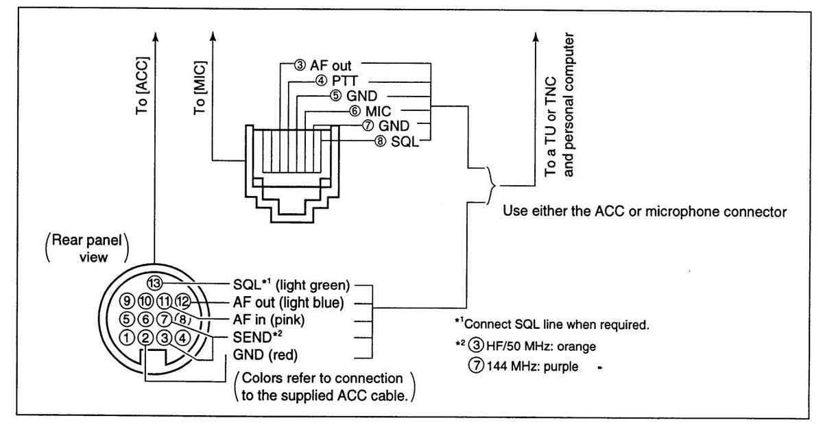
BACCESSORY SOCKET [ACC] (p. 6)
Enables connection to external equipment such as a TNC for data communications, a linear amplifier or an automatic antenna selector/tuner etc. •See page at right for socket information.
GRTTY JACK (RTTY) (p. 33)
Connects an external terminal unit for RTTY (FSK) operation
•The keying polarity and mark/shift frequencies can be selected in quick set mode (pgs. 43, 44).
GCI-V REMOTE CONTROL JACK [REMOTE] (p. 41)
Designed for use with a personal computer for remote operation of transceiver functions.
MICROPHONE CONNECTOR [MIC] (p. 11)
Accepts the supplied microphone (connected in parallel with the front panel's [MIC] connector).
- •See pgs. 1 and 2 for microphone notes.
- •See p. 8 for microphone connector information.
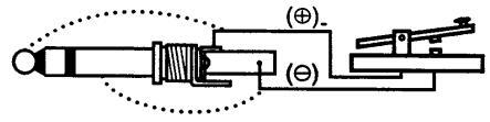
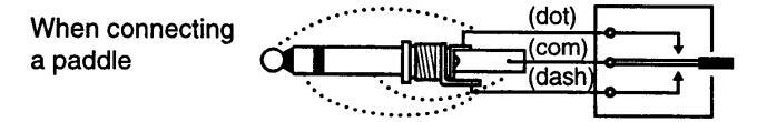
ØELECTRONIC KEYER JACK [KEY] (p. 31)
Accepts a paddle to activate the internal electronic kever.
•Selection between the internal electronic keyer and straight key operation can be made in quick set mode. (p. 44)

BDC POWER SOCKET [DC13.8V] (p. 13)
Accepts 13.8 V DC through the supplied DC power cable

Rear panel view
© EXTERNAL SPEAKER JACK [EXT SP] (p. 12) Accepts a 4–16 Ω speaker.
<b>W TUNER CONTROL SOCKET [TUNER] (p. 12) Accepts the control cable from an optional AH-3 HE AUTOMATIC ANTENNA TUNER
OSPEECH COMPRESSION LEVEL CONTROL [COMP GAIN] (p. 25)
Adjusts the compression level.
•This control is available only when the speech compressor is ON
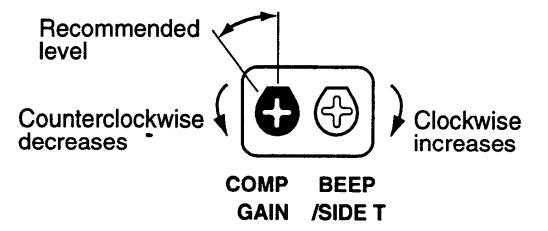
BEEP/SIDETONE CONTROL [BEEP/SIDETONE]
Adjusts the beep tone and CW side tone audio levels.
(p. 25) (b) VOX GAIN CONTROL [VOX GAIN] (p. 25)
Adjusts the VOX sensitivity.
13 910112 5678 1234
ANTI VOX CONTROL [ANTI VOX] (p. 25) Adjusts anti VOX level to prevent the receive audio from activating the VOX.
| ACC | PIN # | NAME | DESCRIPTION | SPECIFICATIONS | COLOF |
|---|---|---|---|---|---|
| 1 | 8 V | Regulated 8 V output. |
Output voltage :8 V ±0.3 V
Output current :Less than 10 mA |
brown | |
| 2 | GND | Connects to ground. | red | ||
| з | HSEND |
Input/output pin (HF/50 MHz).
Goes to ground when transmitting. When grounded, transmits (connected to 8V line thru 2.2 kΩ resistance/144 MHz operation). |
Ground level :-0.5 V to 0.8 V
Input current :Less than 20 mA (HF/50 MHz bands) |
orange | |
| 4 | BDT | Data line for the optional AT-180. | yellow | ||
| 5 | BAND |
Band voltage output.
(Varies with amateur band) |
Output voltage :0 to 8.0 V | green | |
| 6 | ALC | ALC voltage input. |
Control voltage :-4 to 0 V
Input impedance :More than 10 kΩ |
blue | |
| 7 | VSEND |
Input/output pin (144 MHz).
Goes to ground when transmitting. When grounded, transmits (connected to 8V line thru 2.2 kΩ resistance/HF•50 MHz operation). |
Ground level :-0.5 V to 0.8 V
Input current :Less than 20 mA (144 MHz band) |
purple | |
|
Rear panel
view |
8 | 13.8 V | 13.8 V output when power is ON. | Output current : Max. 1 A | gray |
| 9 | TKEY | Key line for the AT-180. | white | ||
| 1 | 10 | FSKK |
RTTY keying input.
Connected in parallel to the [RTTY] jack. |
Ground level :-0.5 to 0.8 V
Input current :Less than 10 mA |
black |
| 11 | MOD | Modulator input. |
Input impedance :10 kΩ
Input level :Approx. 100 mV rms |
pink | |
| 12 | AF |
AF detector output.
Fixed, regardless of [AF] position. |
Output impedance :4.7 kΩ
Output level :100 to 350 mV rms |
light
s blue |
|
| 13 | SQLS |
Squelch output.
Goes to ground when squelch opens. |
SQL open :Less than 0.3 V/5 mA
SQL closed :More than 6.0 V/100 μA |
light
green |
2 GND
④ MOD
1 8 V
2 GND
3 HSEND
BAND
ACC 2
3 HSEND
© SQLS
Ø 13.8 V
⑧ ALC
5 ALC
6 VSEND
© 13.8 V
■ Function display
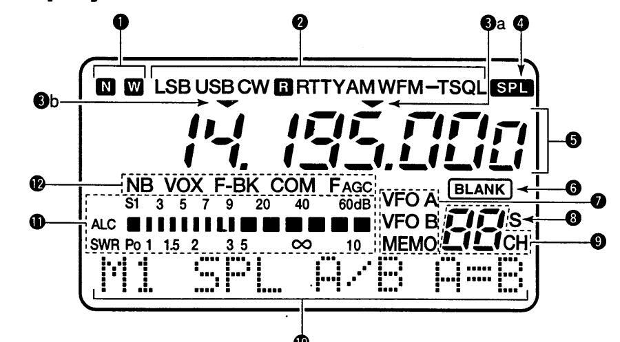
O NARROW/WIDE FILTER INDICATORS
- → "☑" appears when selecting AM narrow or FM narrow modes.
-
When installing an optional narrow filter, narrow mode can be selected in CW, RTTY and SSB modes.
- •When the SSB wide filter is installed, """ appears during wide mode selection.
Ø MODE INDICATORS
Show the operating mode.
OPROGRAMMABLE/1 MHz TUNING STEP INDICATORS
- Sea appears when the programmable tuning step is selected.
- ➡ ❸b appears when the 1 MHz tuning step is selected.
OSPLIT INDICATOR
Shows that the split frequency function is activated.
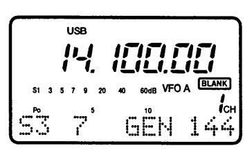
G FREQUENCY READOUT
Shows the operating frequency.
• "C" appears in place of the 1 Hz digit when the call channel is selected.
BLANK INDICATOR
Shows that the displayed memory channel is not programmed.
• This indicator appears both in VFO and memory modes.
ØVFO/MEMORY INDICATORS
VFO A or B appears when VFO mode is selected; MEMO appears when memory mode is selected.
SELECT INDICATOR
Shows that the displayed memory channel is designated as a select memory channel.
<b>O MEMORY CHANNEL NUMBER READOUT
Shows the selected memory channel number.
ODDT MATRIX INDICATORS
These alphanumeric readouts show a variety of information such as current functions of the "F" keys [F1] to [F3], memory channel names, set mode items, etc. See p. 60 for an overview of these indicators.
<b>① METER READOUTS
- Functions as an S-meter while receiving.
- Functions as a power, ALC or SWR meter while transmitting.
Note: The SWR meter does not function in the 144 MHz band.
® FUNCTION INDICATORS
- "NB" appears when the noise blanker is activated.
- "VOX" appears when the VOX function is selected.
- "F-BK" appears when full break-in operation is selected and only "BK" appears when semi break-in operation is selected.
- "COM" appears when the speech compressor is activated.
- "FAGC" appears when the fast AGC function is selected.
■ Microphone (HM-103)
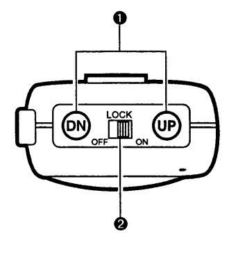

O UP/DOWN SWITCHES [UP]/[DN]
Change the operating frequency.
• Push and hold to change the frequency continuously.
•Tuning step is 50 Hz when no TS indicator appears.
@LOCK SWITCH [LOCK] Locks the [UP]/[DN] switches.
OPTT SWITCH [PTT]
Push and hold to transmit; release to receive.
그는 것 같은 방법에 전해 가지 않는 것 같이 있는 것 같은 것 같이 있는 것 같이 없다.
2
INSTALLATION AND CONNECTIONS
After unpacking, immediately report any damage to the delivering carrier or dealer. Keep the shipping cartons.
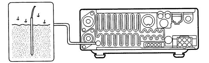
■ Grounding
To prevent electrical shock, television interference (TVI), broadcast interference (BCI) and other problems, ground the transceiver through the GROUND terminal on the rear panel.
For best results, connect a heavy gauge wire or strap to a long earth-sunk copper rod. Make the distance between the GROUND terminal and ground as short as possible.
For a description and a diagram of accessory equipment included with the IC-706MKII, see UNPACKING on p. ii of this manual.
▲ WARNING: NEVER connect the [GND] terminal to a gas or electric pipe, since the connection could cause an explosion or electric shock.
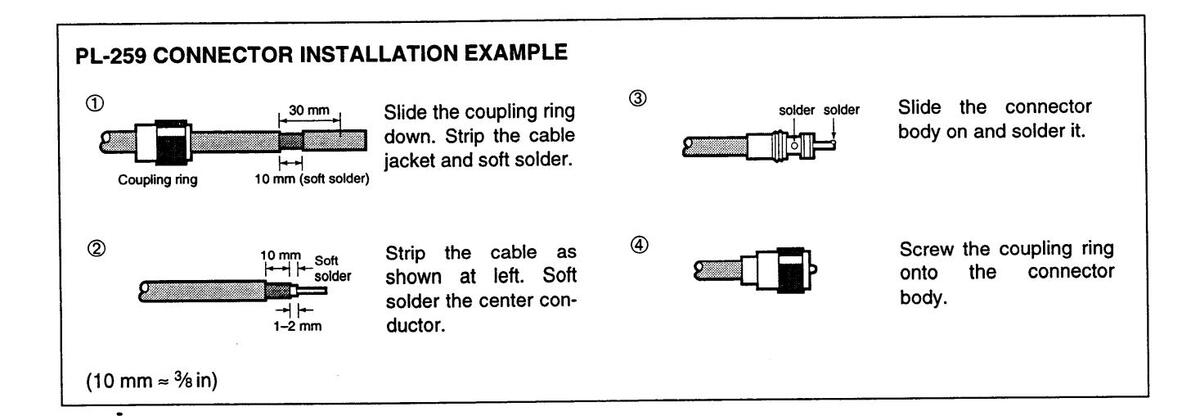
Antenna
Select antenna(s), such as a well-matched 50 Ω antenna, and feedline. The transmission line should be a coaxial cable. 1.5:1 or better of Voltage Standing Wave Ratio (VSWR) is recommended for your required band. Of course, the transmission line should be a coaxial cable.
CAUTION: Protect your transceiver from lightning using a lightning arrestor.
ANTENNA SWR
Each antenna is tuned for a specified frequency range and SWR may be increased out-of-range. When the SWR is higher than approx. 2.0:1, the transceiver's power drops to protect the final transistors. In this case, an optional antenna tuner is useful to match the transceiver and antenna. Low SWR allows full power for transmitting even when using the antenna tuner. The IC-706MKII has an SWR meter to monitor the antenna SWR continuously.
♦ Single body mounting
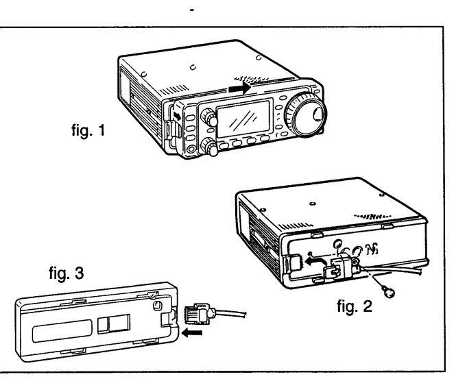
♦ Front panel separation
① While pulling the panel release button towards you, slide the front panel to the right (fig. 1).
- ② Attach the optional OPC-581 to the main body and tighten the supplied screw as in fig. 2.
- ③ Attach the other end of the OPC-581 to the detached front panel as in fig. 3.
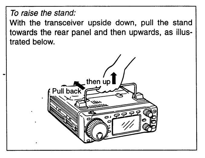
♦ Stand
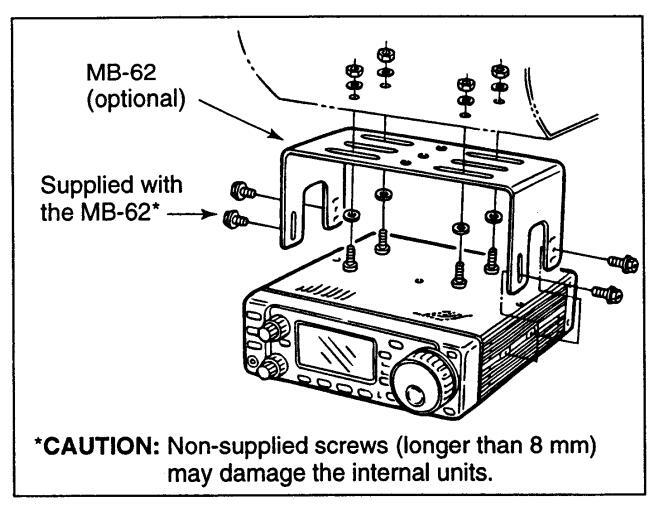
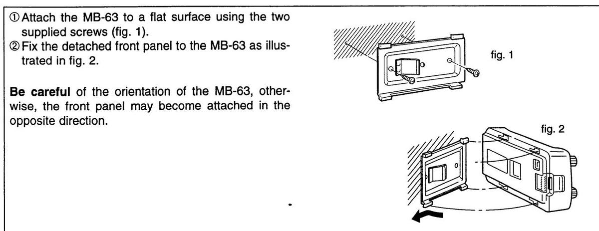
♦ Front panel mounting
■ Required connections
Advanced connections
■ Power supply connections
Use the optional PS-85 DC POWER SUPPLY when operating the IC-706MKII with AC power. Refer to the diagram below for connection.
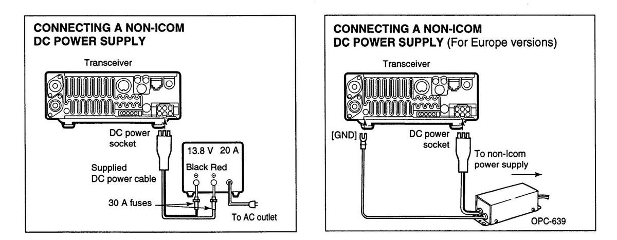
CAUTION: Before connecting the DC power cable, check the following important items. Make sure:
•The [POWER] switch is OFF.
•Output voltage of the power source is 12–15 V when you use a non-loom power supply.
- •DC power cable polarity is correct.
- Red : positive (+) terminal
- Black : negative (-) terminal

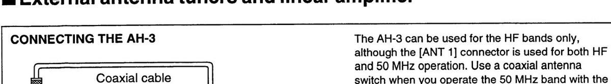
External antenna tuners and linear amplifier
3
FREQUENCY SETTING
When first applying power (CPU resetting)
Before first applying power, make sure all connections required for your system are complete by referring to section 2. Then, reset the transceiver using the following procedure.
Note: Resetting clears all programmed contents in memory channels and returns all initial set mode and quick set mode contents to their default values.
① Make sure the transceiver power is OFE
-
②While pushing [▲] and [▼], push [POWER] to turn power ON
- The internal CPU is reset.
- •The transceiver displays as shown at right when resetting is complete.
♦ M1 display selection
If you can't figure out how to return to the 111 display: While pushing [MENU], turn power ON,
■Initial settings
After resetting the transceiver, set controls and switches as shown in the diagram below.

The transceiver displays its initial frequency and
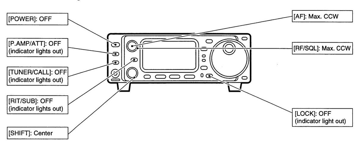
CCW: counterclockwise
Turn power ON, then check the display. If any of the following indicators appear, turn them OFF as follows:
- Tuning step indicators, ▼, (SSB, CW or RTTY): Push [TS].
- •MHz tuning step indicator. • . (FM, WFM or AM): Push [TS]
- •1 Hz frequency readout: Push and hold ITSI.
- Memory mode indicator, MEMO; Use [(F-3)U/M] in the M2 display (p. 60). • Split indicator, SPL: Use [(F-1)SPL] in the M1 display (p. 60).
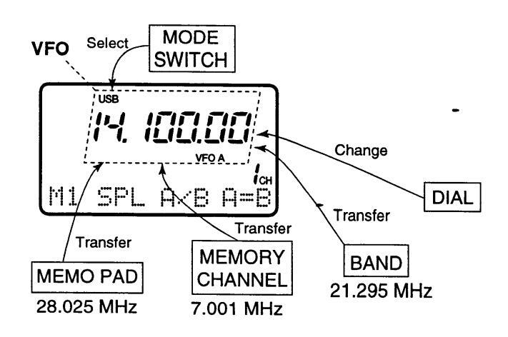
■VFO description
VFO is an abbreviation of Variable Frequency Oscillator, and traditionally refers to an oscillator. The IC-706MKII's VFO can store a frequency and an operating mode.
You can call up a desired frequency to a VFO with the memo pad-read switch (p. 38) or with the memory transfer switch (p. 38). You can also change the frequency with the main dial and select an operating mode with the [MODE] switch or call up previously accessed frequency and modes with the band stacking register (p. 19).
The IC-706MKII has two VFOs, specially suited for split frequency operation. The VFOs are called VFO A and VFO B. You can use the desired VFO to call up a
frequency and operating mode for operation.
•The differences between VFO and memory mode
VFO MODE
Each VFO shows a frequency and operating mode. If the frequency or operating mode is changed, the VFO automatically memorizes the new frequency or operating mode.
When the VFO is selected from another VFO or memory mode, the last-used frequency and operating mode for that VFO appear.
MEMORY MODE (pgs. 35–38)
Each memory channel shows a frequency and operating mode like a VFO. Even if the frequency or mode is changed, the memory channel does not memorize the new frequency or memory mode.
When a memory channel is selected from another memory channel or VFO mode, the memorized frequency and operating mode appear.
[EXAMPLE]
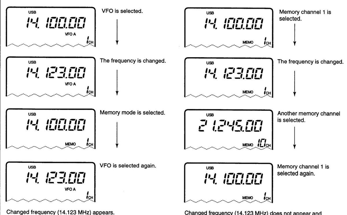
memorised frequency (14.123 MHz) does not appear and memorised frequency (14.000 MHz) appears instead.
Frequency setting
Band selection
All HF ham bands, the 50 MHz band, the 144 MHz band and a general coverage receiver band are included in the IC-706MKII.
Push (▲)BAND1/((♥)BAND1 to select the desired hand
•Pushing [(▲)BAND]/[(♥)BAND1 continuously scrolls through the available bands.
Note: The band stacking register can also be used to select bands. Refer to p. 19.
Programmable tuning steps
Programmable tuning steps are available to suit your operating requirements.
These tuning steps are:
Independently selectable for each mode
•Selectable from 0.01 (FM/WFM/AM only), 0.1, 1, 5, 9, 10, 12.5, 15, 20 and 100 kHz
-
① Push [TS] one or more times until the programmable tuning step indicator, "
V
," appears above the 1 kHz digit
- Botating the main dial changes the frequency according to the set tuning step.
- @ Push [TS] for 2 sec. while the programmable tuning step indicator appears to enter the tuning step selection mode.
•Rotate DIAL appears.
3 Rotate the main dial to set the desired tuning step. •Change the mode and select tuning steps for other modes, if desired.
④ Push [TS] to exit the tuning step selection mode. ⑤ Rotate the main dial to change the frequency according to the set tuning step.
µ°∕B Q= operation.
RotateDIAL
10 kHz tuning step is
oorammable tuning
step indicator
selected for USB
•1 Hz and 10 Hz tuning steps When neither the quick tuning step or programmable tuning step. "V," appear, rotating the main dial changes the frequency in increments of 1 or 10 Hz. These tuning steps are only available in SSB. CW Rotating the main dial and RTTY modes. changes the frequency וא ופקרוו in 10 Hz steps. ① Select SSB, CW or RTTY mode if necessary. 2 Push [TS] for 2 sec. to toggle between the 1 and 10 Hz step settings. Push TS for 2 sec. •When the 1 Hz step is selected, the 1 Hz digit appears in the frequency indication; when the 10 Hz step is Rotating the main dial selected, the 1 Hz digit disappears from the frequency changes the frequency indication. in 1 Hz steps.
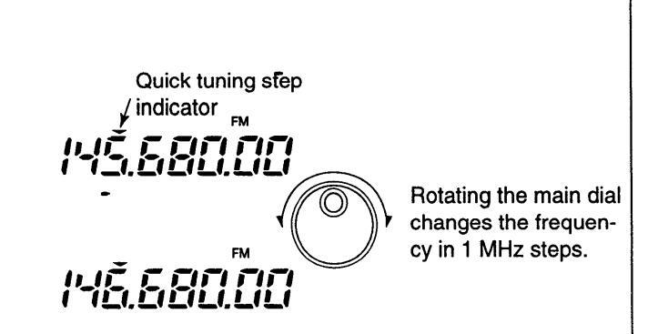
•1 MHz quick tuning step
The quick tuning step function allows you to change the frequency in 1 MHz steps when rotating the main dial. This function is only available in FM, WFM and AM modes.
① Select FM, WFM or AM mode if necessary.
-
② Push [TS] momentarily to toggle between the 1 MHz tuning step and the programmable tuning step.
- •"▼" appears above the 1 MHz indicator when the 1 MHz tuning step is selected.
- •When the 1 MHz tuning step is selected, slow rotation of the main dial changes the frequency in 1 MHz steps and fast rotation of the main dial changes the frequency in 5 MHz steps.
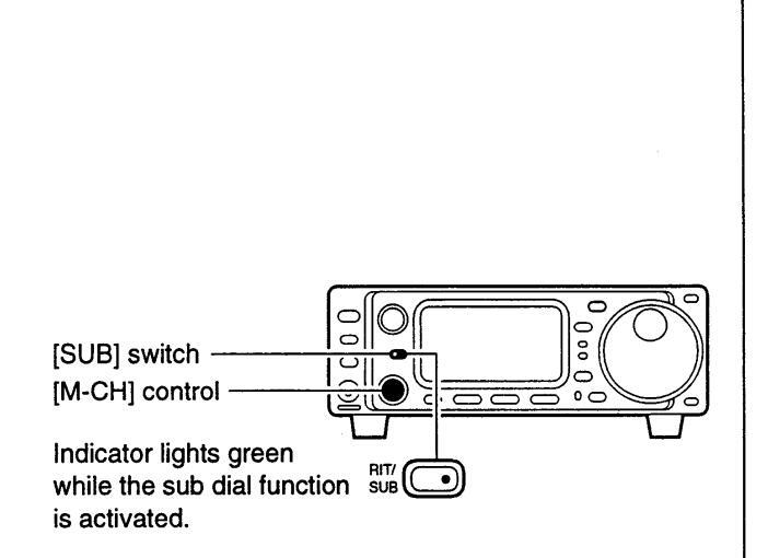
Sub dial function
The sub dial function allows you to change the operating frequency using the [M-CH] control. This gives you more control in tuning since the [M-CH] knob is detented—each click changes the frequency according to the set tuning step. This function is always available in FM, WFM and AM modes. However, in SSB, CW and RTTY modes, the set mode item "Sub dial function," must be set to "FrEq."
- ① Push [RIT/SUB] to turn the sub dial function ON.
- •The [SUB] indicator lights green; if it lights red, the RIT function is activated—sub dial function must be set in initial set mode in this case.
- ② Rotate [M-CH] to change the operating frequency according to the set tuning steps.
- ③ Push [RIT/SUB] again to turn the function OFF.• The [SUB] indicator turns off.
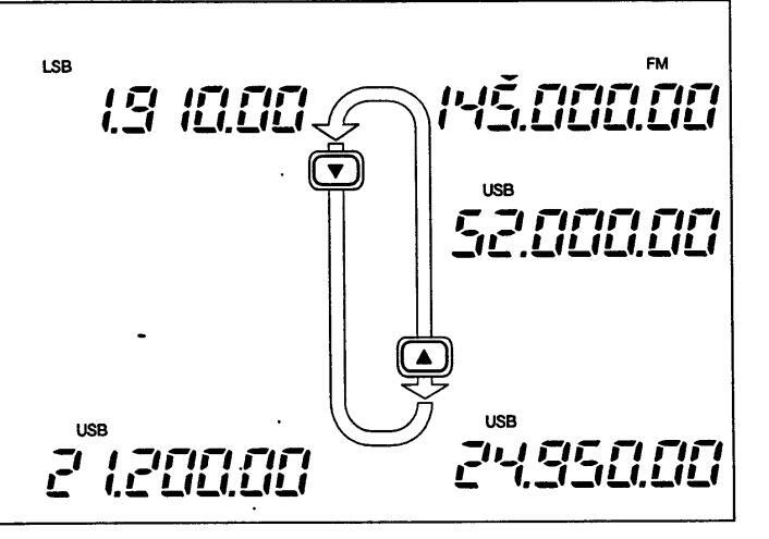
Quick band change function
The quick band change function automatically stores the last frequency and mode used for each band in a band stacking register. This is convenient for contest operation, etc. The table at right shows the quick band change default settings for each band.
① Select 53.
- •Push [DISPLAY] when M or G is displayed.
- Push [MENU] twice to select 53.
- Push [F-1]–[F-3] to select a band stacking register. The default settings for [F-1]–[F-3] are 7, 50 and 144 MHz bands, respectively.
-
③ To change the settings for [F-1]–[F-3] from their defaults, push [F-1]–[F-3] for 1 sec. one or more times to until the desired band appears in the display above the corresponding switch.
- The last-used frequency and mode for the selected band are displayed.
| BAND | FREQUENCY | MODE |
|---|---|---|
| 1.9 MHz | 1.91000 MHz | CW |
| 3.5 MHz | 3.56000 MHz | LSB |
| 7 MHz | 7.06000 MHz | LSB |
| 10 MHz | 10.13000 MHz | CW |
| 14 MHz | 14.10000 MHz | USB |
| General* | 15.10000 MHz | USB |
*General refers to the general coverage receiver (GEH in the display) and the range varies according to version.
Display shows the default bands for the quick band change function.
Display shows [F-2] has been changed from its default of the 50 MHz band to the general receiver band.
| BAND | FREQUENCY | MODE |
|---|---|---|
| 18 MHz | 18.15000 MHz | USB |
| 21 MHz | 21.30000 MHz | USB |
| 24 MHz | 24.95000 MHz | USB |
| 28 MHz | 28.60000 MHz | USB |
| 50 MHz | 50.10000 MHz | USB |
| 144 MHz | 145.00000 MHz | FM |
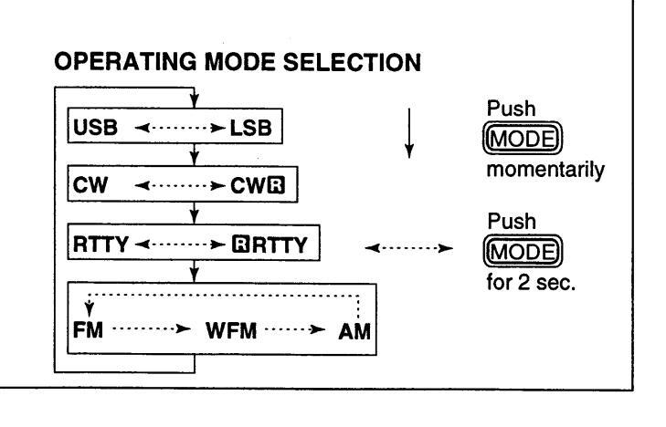
Mode selection
The following modes are available in the IC-706MKII:
SSB (LSB/USB), CW, CW-I (CW reverse), FM, WFM (receive only), AM, RTTY and IRTTY (RTTY reverse).
To select the desired mode of operation push [MODE] one or more times, then push [MODE] for 2 sec., if necessary. See the diagram at right for the order of selection.
• The selected mode is indicated in the function display.
Note: If a desired mode cannot be selected, it may be hidden using Quick Set mode (p. 43).
RECEIVE AND TRANSMIT
Functions for receive
♦ IF shift function
The IF shift function electronically changes the passband frequency of the IF (intermediate frequency) and cuts out higher or lower frequency components of the IF to reject interference. The function shifts the IF frequency up to ±1.2 kHz in 15 Hz steps in SSB/CW/RTTY modes and up to ±250 Hz in 3 Hz steps in CW-12/RTTY-12 modes. The IF shift is not available in FM and AM modes.
-
① Adjust the [SHIFT] control for a minimum interference signal level.
- •The audio tone may be changed while the IF shift is in use.
- (2) Set the shift control to its center position when there is no interference.
• Graphic display
The IF shift can be displayed graphically in graphic display mode.
-
① Select IF shift in graphic display mode.
- Push [DISPLAY] 1 or 2 times when M or 5 is displayed. Push [MENU] one or more times to select the IF shift display, G2 (IF SHIFT appears briefly).
- (2) The IF shift is graphically displayed and updated as the [SHIFT] control is rotated.

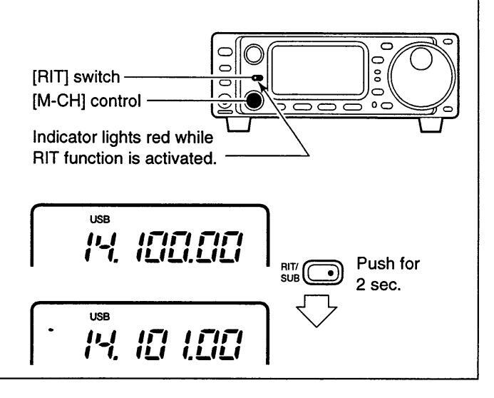
♦ RIT function
The RIT (Receive Incremental Tuning) function compensates for off-frequencies of communicating stations. The function shifts the receive frequency only, up to ±9.99 kHz in 10 Hz steps without moving the transmit frequency. The [SUB/RIT] switch must be set to RIT mode in advance (p. 48).
1 Push [RIT].
- •The [RIT] indicator lights red.
- ② Rotate the [M-CH] control to cancel the off-frequencies.
- •The transmit frequency is not shifted.
- ③ To cancel the RIT function, push [RIT] again. The [RIT] switch indicator goes out.
Calculate function
The shift frequency of the RIT function can be added/subtracted to the displayed frequency.
While the RIT indicator is lit, push and hold [RIT] for 2 sec.
Note: The RIT function is not available in FM, WFM or AM modes regardless of the Initial Set mode setting (p. 48).
4 RECEIVE AND TRANSMIT
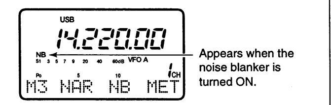
♦ Noise blanker
The noise blanker reduces pulse-type noise such as that generated by automobile ignition systems. This function is not effective for AM broadcast reception, FM modes or for non pulse-type noise. If you don't want to use the noise blanker for AM communications, the "AM noise blanker" item in Initial Set mode must be turned OFF (ON is the default setting—p. 47).
❶ Select Mℑ₊
Push [DISPLAY] 1 or 2 times when 5 or 6 is displayed. Push [MENU] one or more times to select M3.
♦ AGC time constant
The AGC (Automatic Gain Control) controls receiver gain to produce a constant audio output level even when the received signal strength is varied by fading, etc. Use AGC slow for normal phone operation; AGC fast for receiving data and searching for signals. AGC time constant cannot be changed in FM mode.
① Select M4.
- Push [DISPLAY] 1 or 2 times when 5 or 6 is displayed. Push [MENU] one or more times to select №4.
- ② Push [(F-3)AGC] to toggle the AGC time constant between fast and slow.
• "FAGC" appears when the fast time constant is selected.
Preamp and attenuator
The preamp amplifies received signals in the front end circuit to improve the S/N ratio and sensitivity. Turn this function ON when receiving weak signals.
The attenuator prevents desired signals from distorting when very strong signals are near the desired frequency or when very strong electric fields, such as from broadcasting stations, are near your location.
♦ Peak meter hold
INITIAL SET MODE
The peak meter hold function freezes the highest displayed bar segment in any meter function for about 0.5 sec. so that you can more easily read the meter. This function can be turned ON and OFF in initial set mode (see p. 45).
② Push [(F-2)|→|B] to toggle the noise blanker ON and OFF.
•"NB" appears when the noise blanker is turned ON.

Push [P.AMP/ATT] momentarily to turn the preamp ON and OFF; push and hold to turn the attenuator ON. •Lights green when the preamp is ON; lights red when
- the 20 dB attenuator is ON. •Only one of these functions can be activated at a time.
- •Only one of these functions can be activated at a time
Lights green while the preamp is activated; lights red while the attenuator is activated.
| [E) | KA | MP | LE | ]: | ||||
|---|---|---|---|---|---|---|---|---|
| S1 | 3 | 5 |
7
I I |
9 | 20 | 40 | 60dB |
Initial reception of a
signal results in an S- meter reading of 40 dB. |
| S1 | 3 | 5 | 7 | 9 | 20 | 40 | 60dB |
The highest indicated
bar remains displayed for about 0.5 sec. even when the signal strength decreases. |
♦ RF gain and squelch
The IC-706MKII uses the same control, [RF/SQL], to adjust one of either the RF gain or the squelch. [RF/SQL] adjusts either the RF gain or the squelch depending on the operating mode selected and the condition of the RF gain item in initial set mode (see the table at right).
The RF ( Radio Frequency ) gain is used to adjust the receiver gain.
•This control should be set to the 10 o'clock position for normal use.
• Shallow rotation moves the S-meter to the right indicating the signal strength which can be received.
The SQUELCH removes noise output from the speaker (closed condition) when no signal is received. The squelch is particularly effective for FM. It is also available for the other modes.
- •When operating in FM, first rotate the control fully counterclockwise. Then, rotate the control clockwise to the point where the noise just disappears. This is the best position. The squelch does not open for weak signals when it is set too deep.
- A segment appears in the S-meter to indicate the S-meter squelch level.
| •[RF/SQL] control priority | |||||
|---|---|---|---|---|---|
| Initial set mode setting |
USB, LSB,
CW, RTTY |
AM, FM, WFM | |||
| RF gain OFF | SQL | SQL | |||
| RF gain ON | RF GAIN | SQL | |||
Note: The recommended position for RF gain is the 10 o'clock position since this sets RF gain to the max


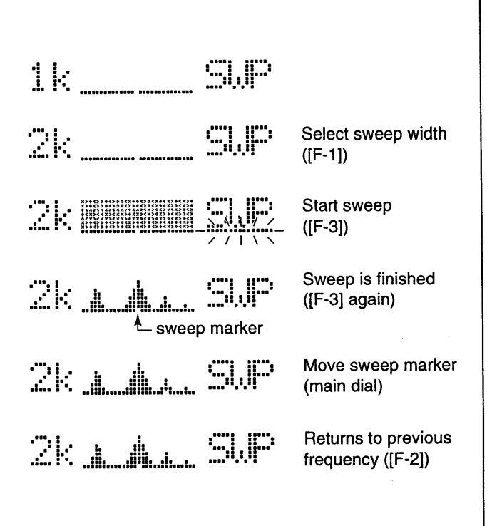
♦ Simple band scope
This function allows you to visually "sweep" an area surrounding the set frequency for other signals. Detected signals are indicated graphically in the dot matrix section of the display.
① Set a mode and frequency.
② Select G1.
- •Push [DISPLAY] 1 or 2 times if M or 5 appears.
- •Push [MENU] one or more times to select 61.
-
③ Push [F-1] one or more times to select the desired steps.
- Each dot corresponds to a step for the indicated frequency.
- •0.5, 1, 2, 5, 10, 20 and 100 kHz can be set for the scope step.
-
④ Push [F-3] to start the sweep.
- •"____" (below 5UP) flashes while sweeping
- •The receive audio is muted while sweeping.
-
⑤ Rotate the main dial if you want to monitor the displayed signals.
- •The sweep marker indicates the location of the displayed frequency in the sweep readout.
- If the displayed frequency is outside of the sweep readout (determined by the sweep width), the sweep marker flashes.
-
© Push [F-2] to return the frequency to the start of a sweep.
- •The sweep marker moves back to the center position.
Note: Use the attenuator or turn OFF the preamp when using the band scope on a band containing a lot of noise.
♦ Optional filter selection
Two optional filters can be installed in the IC-706MKII.
Narrow filters help reject interference from adjacent signals and obtain good selectivity.
Wide filters provide improved audio for SSB operation when no interfering signals are present.
Consult the table below to select a filter most suitable for your operating needs.
Narrow filters for AM/FM modes are standard.
FILTER PRESETTING:
After you install a filter (see p. 53 for installation), you must specify the installed filter in initial set mode (item 19 "OPT. FIL 1" or item 20 "OPT. FIL 2"; see p. 47).
Filter variations
| Name | Mode | Band width |
|---|---|---|
| FL-101* | CW, RTTY | 250 Hz/6 dB |
| FL-232* | CW, RTTY | 350 Hz/–6 dB |
| FL-100* | CW, RTTY | 500 Hz/–6 dB |
| FL-223* | SSB, CW, RTTY | 1.9 kHz/6 dB |
| FL-272 | SSB, CW, RTTY | 2.4 kHz/–6 dB |
| FL-103* | SSB, CW, RTTY | 2.8 kHz/–6 dB |
| FL-94 | AM, FM | 8 kHz/–6 dB |
*Optional filter.
Optional filter installation and selection tables
SSB
| the second se | ||||||
|---|---|---|---|---|---|---|
|
FIL 1
FIL 2 |
No
optional filter |
FL-100 | FL-101 | FL-103 | FL-223 | FL-232 |
| No | W: | W: | W: | W:FL-103 | W: | W: |
| optional | M:FL-272 | M:FL-272 | M:FL-272 | M:FL-272 | M: FL-272 | M:FL-272 |
| filter | N: | N: | N: | N: | N: FL-223 | N: |
| FL-100 | W: | W: | W: | W:FL-103 | W: | W: |
| M:FL-272 | M:FL-272 | M:FL-272 | M:FL-272 | M: FL-272 | M:FL-272 | |
| N: | N: | N: | N: | N: FL-223 | N: | |
| FL-101 | W: | W: | W: | W:FL-103 | W: | W: |
| M:FL-272 | M:FL-272 | M:FL-272 | M:FL-272 | M: FL-272 | M:FL-272 | |
| N: | N: | N: | N: | N: FL-223 | N: | |
| FL-103 | W:FL-103 | W: FL-103 | W: FL-103 | W: FL-103 | W: FL-103 | W: FL-103 |
| M:FL-272 | M: FL-272 | M: FL-272 | M: FL-272 | M: FL-272 | M: FL-272 | |
| N: | N: | N: | N: | N: FL-223 | N: | |
| FL-223 | W: | W: | W: | W:FL-103 | W: | W: |
| M: FL-272 | M: FL-272 | M: FL-272 | M: FL-272 | M: FL-272 | M:FL-272 | |
| N: FL-223 | N: FL-223 | N: FL-223 | N: FL-223 | N: FL-223 | N:FL-223 | |
| FL-232 | W: | W: | W: | W: FL-103 | W: | W: |
| M:FL-272 | M:FL-272 | M:FL-272 | M: FL-272 | M:FL-272 | M:FL-272 | |
| N: | N: | N: | N: | N:FL-223 | N: |
Table key:
W-wide position
M—medium (normal) position N—Narrow position
FILTER ON/OFF:
-
Select M3.
- •Push [DISPLAY] 1 or 2 times if G or S appears.
- •Push [MENU] one or more times to select M3.
-
② Push [(F-1)FIL] momentarily to select the narrow filter; for 2 sec. to select the wide filter.
- D appears when the narrow filter is selected; D appears when the wide filter is selected.
Note: FIL selection is also possible in the G2 IF SHIFT menu. When selecting the narrow filter, the graphic passband is narrowed (see diagram below).

Normal
narrow is selected
CW. RTTY
|
FIL 1
FIL 2 |
No
optional filter |
FL-100 | FL-101 | FL-103 | FL-223 | FL-232 |
|---|---|---|---|---|---|---|
| No | W: | W: | W: | W:FL-103 | W: | W: |
| optional | M:FL-272 | M:FL-272 | M:FL-272 | M:FL-272 | M: FL-272 | M: FL-272 |
| filter | N: | N:FL-100 | N:FL-101 | N: | N: FL-223 | N: FL-232 |
| FL-100 | W: | W: | W: FL-272 | W:FL-103 | W:FL-272 | W:FL-272 |
| M:FL-272 | M:FL-272 | M: FL-100 | M:FL-272 | M:FL-223 | M:FL-100 | |
| N:FL-100 | N:FL-100 | N: FL-101 | N:FL-100 | N:FL-100 | N:FL-232 | |
| FL-101 | W: | W: FL-272 | W: | W:FL-103 | W: FL-272 | W:FL-272 |
| M:FL-272 | M: FL-100 | M:FL-272 | M:FL-272 | M: FL-223 | M:FL-232 | |
| N:FL-101 | N: FL-101 | N:FL-101 | N:FL-101 | N: FL-101 | N:FL-101 | |
| FL-103 | W: FL-103 | W: FL-103 | W: FL-103 | W: FL-103 | W: FL-103 | W: FL-103 |
| M: FL-272 | M: FL-272 | M: FL-272 | M: FL-272 | M: FL-272 | M: FL-272 | |
| N: | N: FL-100 | N: FL-101 | N: | N: FL-223 | N: FL-223 | |
| FL-223 | W: | W:FL-272 | W:FL-272 | W:FL-103 | W: | W:FL-272 |
| M:FL-272 | M:FL-223 | M:FL-223 | M:FL-272 | M: FL-272 | M:FL-223 | |
| N:FL-223 | N:FL-100 | N:FL-101 | N:FL-223 | N: FL-223 | N:FL-232 | |
| FL-232 | W: | W: FL-272 | W: FL-272 | W: FL-103 | W: FL-272 | W: |
| M: FL-272 | M: FL-100 | M: FL-232 | M: FL-272 | M: FL-223 | M:FL-272 | |
| N: FL-232 | N: FL-232 | N: FL-101 | N: FL-232 | N: FL-232 | N:FL-232 |
| AN | Normal | FL-94 |
|---|---|---|
| Narrow - | FL-272 | |
| EN | Normal | FL-23+SFPC455E |
| FIVI | Narrow | FL-94 |
■ Functions for transmit
♦ Output power and mic gain
•Setting output power
- ① Push [DISPLAY] for 2 sec. to select quick set mode. ② Push [MENU] one or more times to select ①1_RF
- (2) Push [MENU] one or more times to select U1 RF POWER.
- ③ Rotate the main dial to select the desired output. •Output power is displayed in 11 steps (L, 1–9 and H) but is continuously selectable.
- Push [DISPLAY] to exit quick set mode.
Available power
| BAND | SSB/CW/RTTY/FM | AM* |
|---|---|---|
| HĘ | 5–100 W | 4–40 W |
| 50 MHz | 5–100 W | 4–40 W |
| 144 MHz | 2–20 W | 2–8 W |
*Carrier power
Setting microphone gain
Microphone gain must be adjusted properly so that your signal does not distort when transmitted.
- ① Select SSB or another phone mode.
- 2 Push [DISPLAY] for 2 sec. to select quick set mode.
-
③ Push [MENU] one or more times to select @2 MIC GAIN.
- •The ALC meter is selected automatically when operating in SSB mode.
- While speaking into the microphone adjust the mic gain so that the ALC meter does not peak past the ALC zone.
- ⑤ Push [DISPLAY] to exit quick set mode.
♦ Meter function
The bar meter in the function display acts as an S-meter (for relative signal strength, except in WFM mode) during receive and can be selected for one of three types during transmit.
Select M3.
- •Push [DISPLAY] 1 or 2 times when 5 or G appears.
- •Push [MENU] one or more times to select M3.
-
② Push [(F-3)MET] one or more times to select the desired meter function.
- •The display indication changes as in the table at right.

|
DISPLAY
INDICATION |
MEASUREMENT |
|---|---|
| Ро | Indicates the relative RF output power. |
| ALC |
Indicates the ALC level. When the
meter movement shows the input signal level exceeds the allowable level, the ALC limits the RF power. In such cases, reduce the microphone gain (see above). |
| SWR |
Indicates the SWR over the transmis-
sion line. |
Note: The SWR meter cannot be used for the 144 MHz band since the meter activates for the [ANT 1] connector only.
♦ Speech compressor
The IC-706MKII has a built-in, low distortion speech compressor circuit. This circuit increases your average talk power in SSB mode and is especially useful for DX'ing when the receiving station is having difficulty copying your signal.
① Select USB or LSB mode.
-
2 Select the ALC meter.
- Push [DISPLAY] 1 or 2 times to select ↑, if necessary. Push [MENU] one or more times to select ↑/3, then push [(F-3)↑/4ET] one or more times to select "ALC."
- Select the mic gain display in quick set mode. •Push [DISPLAY] for 2 sec.
- •Push [MENU] one or more times to select 02 MIC GAIN.
-
④ Adjust the mic gain.
- While transmitting at your normal voice level, the ALC meter should read at about the middle of the ALC zone. Be sure the mic gain is in the range of 2 to 5.
- ⑤ Select M4.
- Push [DISPLAY] 1 or 2 times to select M, if necessary. Push [MENU] one or more times to select M4.
- ⑥ Push [(F-2)①竹], then adjust [COMP GAIN] so that the ALC meter reads within the ALC zone whether you speak softly or loudly.
Note: When the ALC meter peaks above the ALC zone, your transmitted voice may be distorted.

♦ VOX operation
The VOX (Voice-operated Transmission) function toggles between transmit and receive with your voice. This function provides an opportunity to input log entries into your computer, etc., while operating.
- ① Set [VOX GAIN] and [ANTI-VOX] on the transceiver's side panel max. counterclockwise.
- ② Select 144, then turn the VOX function ON. •Push [DISPLAY] 1 or 2 times when 5 or G appears. •Push [MENU] one or more times to select 144. •Push [(F-1)UUX] to turn the function ON.
- ③ Select VOX DELAY in quick set mode
- Push [DISPLAY] for 2 sec. then push [MENU] one or more times to select Q3.
- While speaking into the microphone, rotate [VOX GAIN] clockwise until the transceiver is transmitting.
- SAdjust the delay time as desired with the main dial (while UOX DELAY is indicated).
- (6) If the receive audio from the speaker toggles the transceiver to transmit during receive, adjust the [ANTI-VOX] control to the point where it has no effect.
⑦ Push [DISPLAY] to exit quick set mode.
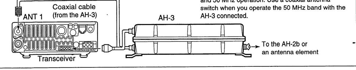
The AT-180 automatic antenna tuner matches the IC-706MKII to the connected antenna automatically. Once the tuner matches an antenna, the variable capacitor angles are memorized as a preset point for each frequency range (100 kHz steps). Therefore, when you change the frequency range, the variable capacitors are automatically preset to the memorized point.
CAUTION: NEVER transmit with the tuner-ON when no antenna is connected. This will damage both the transceiver and the antenna tuner.
Note:
•The AT-180 cannot be used for the 144 MHz band. •When operating on the 144 MHz band, pushing the
- tuner switch selects the call channel (p. 33).
- •The AT-180 can match both HF and 50 MHz bands. However, operation is different for the HF and 50 MHz bands.
TUNER OPERATION
• For the HF band:
Push [TUNER] to turn the tuner ON. The antenna is tuned automatically during transmission when the antenna SWR is higher than 1.5:1.
[TUNER/CALL]
Lights to indicate the AT-180 is turned ON
•When the tuner is OFF, the [TUNER] light goes out.
• For the 50 MHz band:
Push and hold [TUNER] to tune the antenna. If the [TUNER] light flashes slowly while transmitting, push and hold [TUNER] again to re-tune the antenna.
[TUNER/CALL]
Flashes to indicate re-tuning is necessary.
MANUAL TUNING
During SSB operation on HF bands at low voice levels, the AT-180 may not be tuned correctly. In such cases, manual tuning is helpful.
Push and hold [TUNER] for 1 sec. to start manual tuning.
•CW mode is selected, a side tone is emitted, and the [TUNER] light flashes; then, the previous mode is selected.
[TUNER/CALL]

Push and hold for 1 sec. to start manual tuning.
If the tuner cannot reduce the SWR to less than 1.5:1 after 20 sec. of tuning, the [TUNER] light goes out. In this case, check the following:
- the antenna connection and feedline
- •the antenna SWR (p. 25; meter function)
Through inhibit (HF bands only)
The AT-180 has a through inhibit condition. When selecting this condition, the tuner can be used at poor SWR's. In this case, automatic tuning in the HF bands activates only when exceeding SWR 3:1. Therefore, manual tuning is necessary each time you change the frequency. Although termed "through inhibit," the tuner will be "through" if the SWR is higher than 3:1 after tuning.
CONVENIENT
• Tuner sensitive condition (HF bands only)
If you require critical tuning at any time during transmission, select the tuner sensitive condition. See p. 55 for selection.
•Automatic tuner start (HF bands only)
If you want to turn OFF the tuner under conditions of VSWR 1.5:1 or less, use "automatic tuner on" and turn the tuner OFF. See p. 46 for turning the function ON and OFF.
그는 것 같은 것 같
4 RECEIVE AND TRANSMIT
♦ Optional AH-3 AUTOMATIC ANTENNA TUNER operation
The AH-3 matches the IC-706MKII to a long wire antenna more than 3 m/10 ft long (3.5 MHz and above) or more than 12 m/40 ft long (1.8 MHz and above).
- •See p. 14 for connection.
- See the AH-3 instruction manual for AH-3 installation and antenna connection details.
AH-3 setting example:
For mobile operation
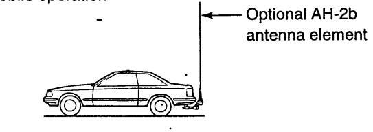
For outdoor operation

A WARNING: HIGH VOLTAGE! NEVER touch the antenna element while tuning or transmitting.
NEVER operate the AH-3 without an antenna wire. The tuner and transceiver will be damaged.
NEVER operate the AH-3 when it is ungrounded.
Transmitting before tuning may damage the transceiver. Note that the AH-3 cannot tune when using a ½ λ long wire or multiple of the operating frequency.
Note: The AH-3 can be used for HF bands only. It cannot be used for the 50 MHz or 144 MHz bands.
AH-3 operation
Tuning is required for each frequency. Be sure to re-tune the antenna before transmitting when you change the frequency—even slightly.
① Set the desired frequency in an HF band. •The AH-3 will not operate on frequencies outside of ham bands.
-
2 Push and hold [TUNER] for 2 sec.
- The [TUNER] light flashes and "CW" appears while tuning.
Push [TUNER] for 2 sec.

③ The [TUNER] light lights constantly when tuning is complete.
•When the connected wire cannot be tuned, the [TUNER] light goes out, the AH-3 is bypassed and the antenna wire is connected to the antenna connector on the transceiver directly.
(TUNER).
CONVENIENT
• PTT tune function
The AH-3 is always tuned when the PTT is pushed after the frequency is changed (more than 1%). This function removes the "push and hold [TUNER]" operation and activates first transmission on the new frequency. This function is turned ON in initial set mode, item 13 (p. 46).
■ Split frequency operation
Split frequency operation allows you to transmit and receive on two different frequencies. Split frequency operation uses 2 frequencies, one in VFO A and the other in VFO B.
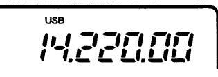
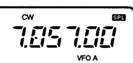
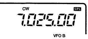
Following is an example of setting 7.057 MHz, CW mode in VFO A (for receive) and 7.025 MHz, CW mode in VFO B (for transmit).
① Select VFO A and set the frequency to 7.057 MHz/CW.
•[(F-2) / ] is available when M1 appears.
•[(F-3)U/M] is available when M2 appears.
② Push or push and hold [(F-1)SPL] in the №1 display.
- ➡ Push [SPL]: activates split only.
- ➡ Push and hold [SPL]: activates the quick split below.
③ To change the receive frequency, rotate the main dial; to change the transmit frequency, rotate the main dial while pushing [(F-3)☆FC].
- •The transmit frequency can be monitored while pushing [(F-3)XFC].
- Split operation is now set for receive on 7.057 MHz/CW and transmit on 7.025 MHz/CW.
To exchange the transmit and receive frequencies, push [(F-2)A/B] in M1.
CONVENIENT
The G3 display conveniently shows the transmit frequency during split frequency operation and [(F-3)[]] allows you to change the transmit frequency.
•Split lock function
The split lock function is convenient for changing only the transmit frequency. Otherwise, accidentally releasing the [(F-3) FC] switch while rotating the main dial changes the receive frequency. The split lock's effectiveness can be selected in initial set mode (item 18) for both receive and transmit frequencies; or only the receive frequency. (p. 47)
♦ Quick split function
In [1], when you push [(F-1)5PL] for 2 sec., split frequency operation is turned ON and VFO B is automatically changed according to the plus/minus preprogrammed shift frequency set in initial set mode (or equalized when 0 kHz is programmed as the split shift frequency). This shortens the time needed to start split frequency operation—great for DX'ing.
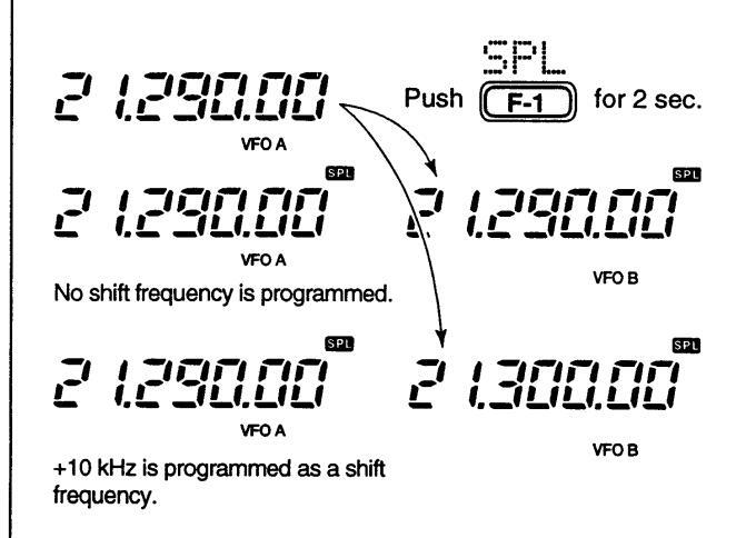
The quick split function is ON by default. If desired, it can be turned OFF in initial set mode (p. 46). In this case, pushing [(F-1) FL] for 2 sec. has the same effect as pushing [(F-1) FL] momentarily as in normal split operation.
PROGRAMMING SPLIT SHIFT FREQUENCY
① Push [POWER] to turn power OFF.
- (2)While pushing [LOCK], push [POWER] to turn power ON and enter initial set mode.
-
③ Select "SPL_OFFSET" using [MENU], [M-CH] or the [▲]/[▼] keys, then rotate the main dial to select the desired split offset.
- •The split offset can be selected from -4000 kHz to +4000 kHz.

Note: This setting is not valid for FM operation. This is because FM operation uses the duplex setting for repeater operation (next page).
♦ Repeater operation
A repeater amplifies received signals and retransmits them at a different frequency. When using a repeater, the transmit frequency is shifted from the receive frequency by an offset frequency. A repeater can be accessed using split frequency operation with the shift frequency set to the repeater's offset frequency.
-
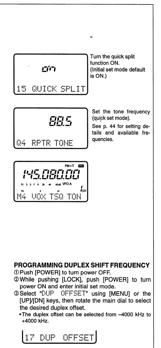
① Set the offset frequency and turn ON the quick split function in initial set mode in advance (p. 46).
- If the quick split function is turned OFF, both transmit and receive must be set separately.
- ② Push [MODE] one or more times to select FM mode, then set the receive frequency.
-
③ Select a suitable tone frequency or the 1750 Hz tone burst in guick set mode.
- Push [DISPLAY] for 2 sec., then push [MENU] one or more times to select "Q4 RPTR TONE." If FM mode has not been selected, this item does not appear.
- Rotate the main dial to set a subaudible tone frequency or the 1750 Hz tone burst function. Push [DISPLAY] to exit quick set mode.
- Push [(F-1)SPL] for 2 sec. (in the 111 display) to
- activate the split frequency function (duplex function) with the pre-selected offset.
- •When a subaudible tone frequency (excepting 1750 Hz) is selected in ③, "FM-T" is selected simultaneously.
-
(5) Push and hold [PTT] to transmit; release [PTT] to receive.
- •When a 1750 Hz tone burst is selected, push and hold [(F-3)TŪN] in the [14] display while pushing [PTT] to send the 1750 Hz tone burst.
- ⑥ To check the repeater input frequency (direct signal from the other station), push and hold [(F-3)☆FC] in the M1 display.
- ⑦ To return to simplex operation, push [(F-1)SPL].
CONVENIENT
Each memory channel can store a tone frequency (subaudible tones or a tone burst) and an offset frequency, as well as the operating frequency. Store repeater information into memory channels for quick and easy access to repeaters.
4

พ้น แก่ง รร้อ รกพ
tion ON and OFF. •When tone squelch is turned ON, "TSQL" appears in the display
© Communicate in the usual manner.
Push [PTT] to transmit: release to receive.
■ Functions for CW
♦ Connections for CW
♦ CW operation
① Connect a paddle or straight key as above. @ Select CW (or CWI) mode with [MODE]. 3 Set CW break-in operation as semi break-in, full CW mode and semi break-in or OFF break-in operation is יארובקרוו • Push [DISPLAY] one or two times to select 1, if necessary. selected • Push [MENU] one or more times to select 114. •Push [(F-2)BRK] one or more times to select the desired BRK AGO condition ▶ "F-BK": full break-in • "BK": semi break-in No indicator: no break-in (ACC socket connection is necessary as above.) ④ Set the CW delay time when semi break-in operation is selected. Delay time of 1.0 sec. is → Push [DISPLAY] for 2 sec. to select quick set CW selected in quick set mode; push [MENU] one or more times to select mode for semi break-in Q3 BK-IN DELAY: then rotate the main dial operation. to set the desired delay time (see p. 43 for details). Q3 BK-IN DELAY
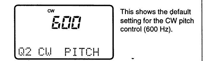
♦ CW pitch control
QUICK SET MODE
The received CW audio pitch and monitored CW audio pitch can be adjusted to suit your preferences (300 to 900 Hz) without changing the operating frequency.
① Push [MODE] one or more times to select CW mode.
② Select CIJ PITCH in quick set mode.
Push [DISP] for 2 sec. then push [MENU] one or more times.
③ Rotate the main dial to set the desired pitch. ④ Push [DISPLAY] to exit quick set mode.
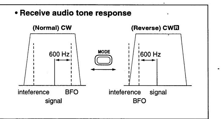
♦ CW reverse mode
The CWG (CW Reverse) mode receives CW signals with a reverse side CW carrier point like that of LSB and USB modes. Use this mode when interference signals are near the desired signal and you want to change the interference tone.
- ① Push [MODE] one or more times to select CW mode.
- ② Push and hold to toggle between CW and CW modes.
• Check the interference tone.
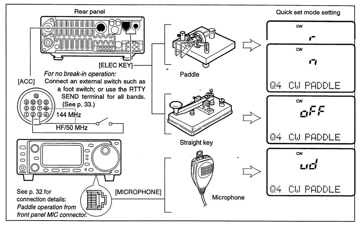
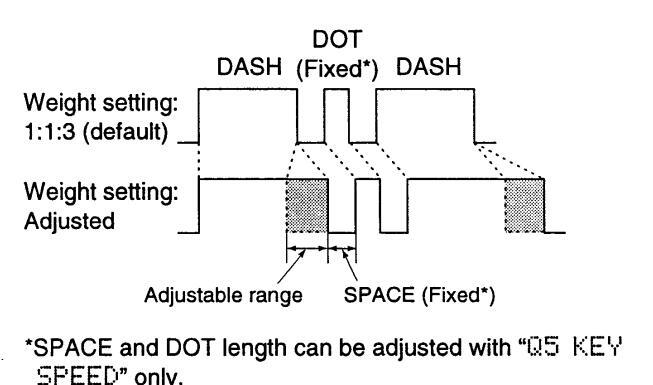
The IC-706MKII has an electronic keyer. Both keying speed and weight (the ratio of dot:space:dash) can be set in quick set mode.
• Setting the electronic keyer
① Select CW mode with [MODE].
② Push [DISPLAY] for 2 sec. to enter quick set mode. ③ Push [MENU] one or more times to select item 04
- 3 Push [MENU] one or more times to select item 04 CU PADDLE, then rotate the main dial to select the paddle type.
- •When "ud" is selected, the up/down switches on the microphone can be used as a paddle.
- Push [MENU] two more times to select item Q6 RATIO, then rotate the main dial to select the desired weight.
•Key weight can be selected from 2.8 to 4.5.
•Check the selected ratio with the side tone function in
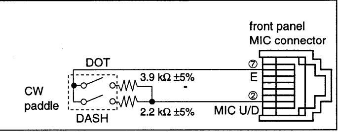
Paddle operation from front panel MIC connector Connect a CW paddle as at right to operate an electronic keyer from the front panel MIC connector.
- •This function is available from the front panel mic connector only.
- Resistor tolerance must be below 5%.
- Connect straight key to "DOT" side.
CW mode.
⑤ Push [DISPLAY] momentarily to exit quick set mode.
KEYING WEIGHT EXAMPLE: morse code "K"
Functions for RTTY
♦ Connections for RTTY (FSK)

♦ Connections for AFSK
♦ RTTY (FSK) operation
- ① Connect a terminal unit as at left.
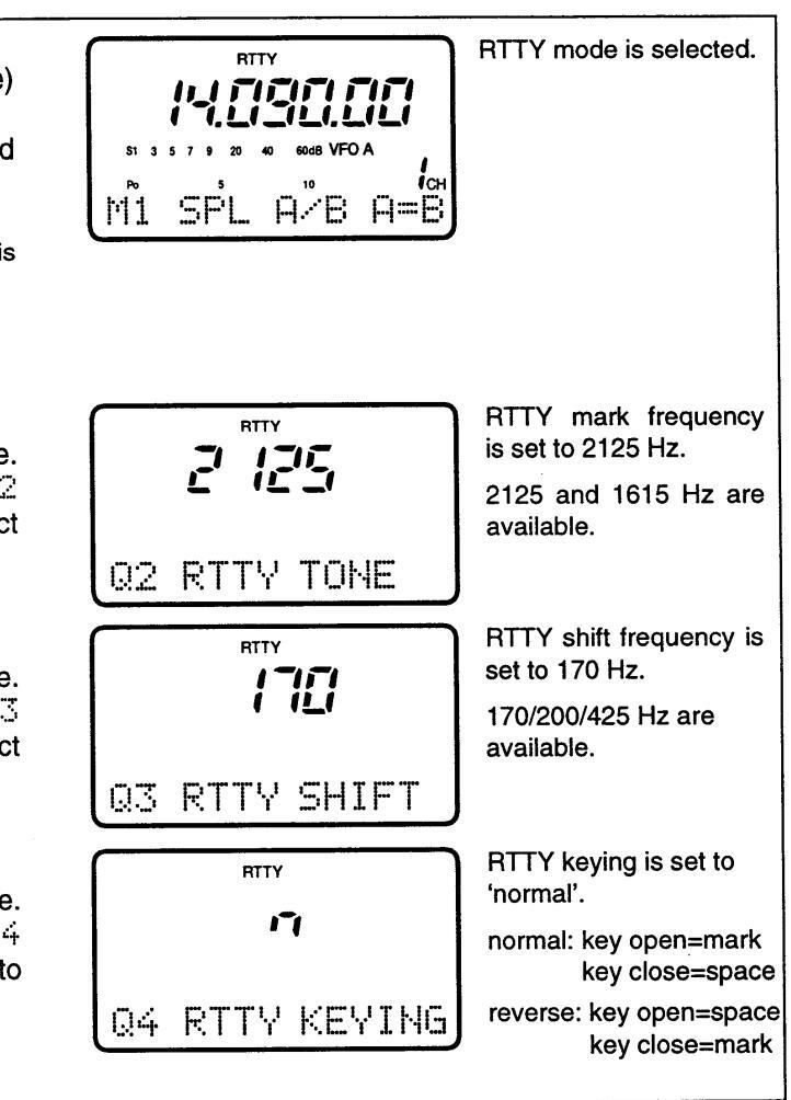
- ② Select RTTY (or BRTTY—see bottom of page) mode with [MODE].
- ③ Select the desired FSK tone/shift frequencies and keying polarity as below.
- ④ Set the desired frequency with the main dial. Use [(F-1)1/4] in the M4 display when critical setting is required.
- ⑤ Operate the €onnected PC or TNC (TU).
PRESETTING FOR RTTY
Tone frequency
- 1 Push [DISPLAY] for 2 sec. to select quick set mode.
- ② Push [MENU] one or more times to select Q2 RTTY TONE; then rotate the main dial to select the desired tone frequency (p. 43).
Shift frequency
① Push [DISPLAY] for 2 sec. to select quick set mode. ② Push [MENU] one or more times to select Q3 RTTY SHIFT; then rotate the main dial to select the desired shift frequency (p. 43).
RTTY keying
- ① Push [DISPLAY] for 2 sec. to select quick set mode.
- ② Push [MENU] one or more times to select Q4 RTTY KEYING; then rotate the main dial to select the desired keying polarity (p. 43).
♦ RTTY (AFSK) operation
- ① Connect a terminal unit as at left.
- ② Select RTTY (or GRTTY) mode with [MODE].
- ③ Select the desired FSK tone/shift frequencies and keying polarity as below.
- ④ Set the desired frequency with the main dial. Use [(F-1)1/4] in the M4 display when critical setting is required
- © Operate the connected PC or TNC (TU).
PRESETTING FOR RTTY
Tone frequency
Same as above.
Shift frequency
Same as above.
RTTY keying
Same as above.
RTTY reverse mode
Received characters are occaisonally garbled when the receive signal is reversed between MARK and SPACE. This reversal can be caused by incorrect TNC connections, settings, commands, etc.
To receive a reversed RTTY signal correctly, select RTTY (RTTY reverse) mode.
-
Push [MODE] for 1 sec. (while RTTY is selected) to select BRTTY mode.
- Check the receive signal.

MEMORY AND SCAN OPERATIONS
Memory channels
The transceiver has 101 memory channels (plus 1 call channel). Memory mode is useful for quickly changing to often-used frequencies.
All 101 memory channels are tuneable which means the programmed frequency can be tuned temporarily with the main dial, etc., in memory mode.
Note: During split frequency operation, programmed memory contents can be called up to the SUB readout (dot matrix portion of the display).
|
MEMORY
CHANNEL |
MEMORY
CHANNEL NUMBER |
CAPABILITY |
TRANSFER
TO VFO |
OVER-
WRITING |
CLEAR |
|---|---|---|---|---|---|
|
Regular
(split memory) |
1–99 |
Independent transmit and receive
frequencies and one mode in each memory channel. In addition, tone frequencies (or 1750 Hz tone burst) can also be stored for repeater use. |
Yes | Yes | Yes |
| Scan edges | P1, P2 |
One frequency and one mode in
each memory channel as scan edges for programmed scan. |
Yes | Yes | Νο |
|
Call channel
(split memory) |
С | Same as regular, however, only the 144 MHz band can be programmed. | Yes | Yes | No |
Memory channel selection

- •Push [DISPLAY] 1 or 2 times to select 1. •Push [MENU] one or more times to select 1.
- ② Push [(F-3)[///1] to select memory mode.
-
③ Rotate [M-CH] to select the desired memory channel.
- •All memory channels including blank channels can be selected.
- •[UP]/[DN] on the microphone changes the frequency.
- ④ To return to VFO mode, push [(F-3)↓/1] again.

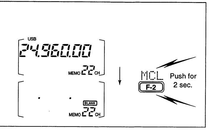
Memory clearing
Any unnecessary memory channels can be cleared. The cleared memory channels become blank channels.
- ① Push [(F-3)U/M] in the M2 display to select memory mode.
- ② Rotate [M-CH] to select a memory channel to be cleared.
- ③ Push [how and programmed frequency and operating mode disappear and "BLANK" appears.
- ④To return to VFO mode, push [(F-3)以게] again.
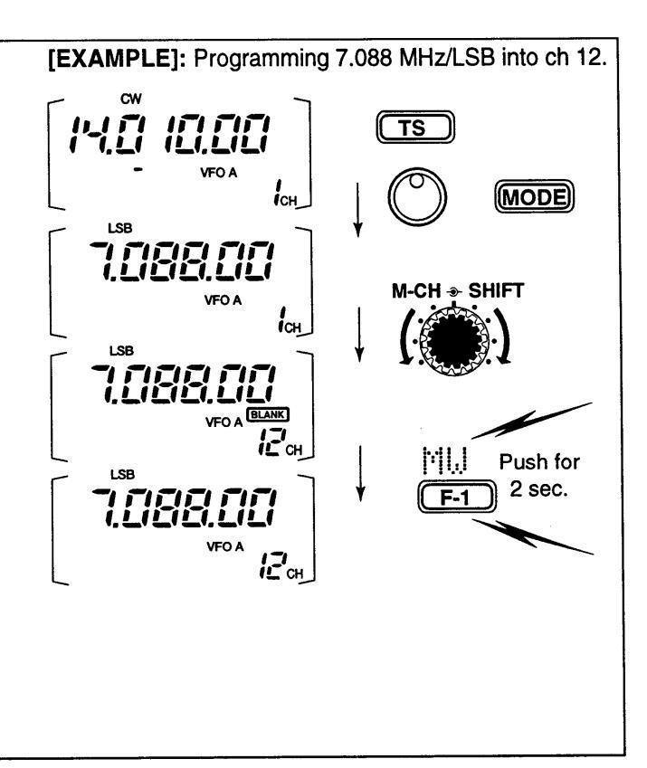
Memory/call programming
• Programming in VFO mode
-
① Select M2 functions.
- •Push [DISPLAY] 1 or 2 times to select 1.
•Push [MENU] one or more times to select the M2 functions.
② Set the desired frequency and operating mode in VFO mode.
• If you want to program the split frequency function, program both receive and transmit frequencies into VFO A and B, then turn ON the split function.
- If you want to program a repeater function, set a tone frequency (p. 44) in addition to the receive/transmit frequencies.
-
③ Rotate [M-CH] to select the desired memory channel, or the call channel (144 MHz band only).
- Select memory mode to confirm the contents, if desired. • "BLANK" appears if the selected memory channel is a blank channel (and does not have contents).
- ④ Push [(F-1)][1][J] for 2 sec. to program the displayed frequency and operating mode into the memory channel.
To check the programmed contents, push [(F-3)U/M] to select memory mode; or, push [CALL] to select the call channel.
EXAMPLE]: Programming 21.280 MHz/USB into ch 18. M2 func e M2 func e desired ank chan mode. displayed memory CW <
• Programming in memory mode
① Select M2 functions.
- •Push [DISPLAY] 1 or 2 times to select M.
- •Push [MENU] one or more times to select the M2 functions.
-
© Select memory mode, then select the desired memory channel with [M-CH].
- •Push [▲]/[▼] when you want to program blank channels.
- ③ Set the desired frequency and operating mode.
- Push [(F-1)][1], for 2 sec. to program the displayed frequency and operating mode into the memory channel.
Frequency transferring
The frequency and operating mode can be transferred from memory mode to VFO mode.
⑦ Select VFO mode with [(F-3)↓/↑↑] in the №2 display.
-
2 Select a memory channel with [M-CH].
- Select memory mode to confirm the memory channel's contents, if desired; then return to VFO mode.
- "BLANK" appears if the selected memory channel is a blank channel (and does not have contents). In this case transferring is not possible.
-
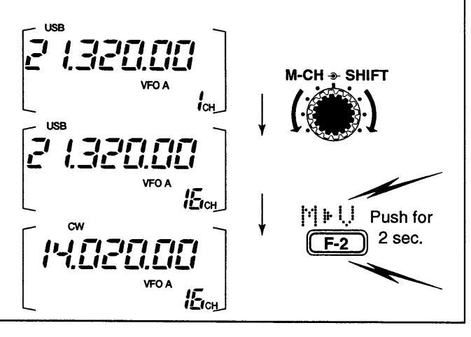
③ Push [(F-2)[] ⊧ [,]] for 2 sec. to transfer the frequency and operating mode.
- •Transferred frequency and operating mode appear in the display.
- •"怕⊧∪" does not appear in memory mode.
[EXAMPLE]: Transferring contents of memory 16. Operating frequency: 21.320 MHz/USB (VFO) Contents of memory 16: 14.020 MHz/CW
Memory names
All memory channels (including scan edges and the call channel) can be tagged with alphanumeric names of up to 9 characters each.
• Calling up memory names
① Select the G4 display.
- ➡ Push [DISPLAY] 1 or 2 times to select G.
- ➡ Push [MENU] one or more times to select the G4 display.
@ Select a memory channel with [M-CH].
• Editing (programming) memory names
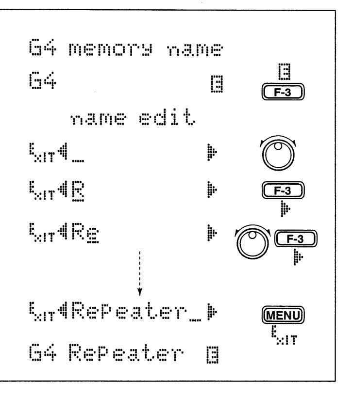
- ① Call up the desired memory (channel) name as above.
- ② Push [(F-3)] to enter memory name edit mode. •"name edit." appears briefly, then a flashing cursor appears under the first character position.
- ③ Rotate the main dial to select the desired character, then advance the cursor position.
- •[(F-3)▶] increments the cursor position; [(F-1)4] decrements the cursor position.
- •[(F-2)] overwrites the character with a space.
- Repeat this procedure until all desired characters have been selected.
- Dush [(MENU)Exit] to exit memory name edit mode. The G4 display reappears and the programmed memory name is displayed.
All common keyboard characters (ASCII characters 33 to 126) can be used, including numerals and punctuation marks.
Memo pads
The transceiver has a memo pad function to store frequency and operating mode for easy write and recall. The memo pads are separate from memory channels.
The default number of memo pads is 5, however, this can be increased to 10 in initial set mode if desired (p. 46).
• Writing frequencies and operating modes into memo pads
① Select the 51 display.
- Push [DISPLAY] 1 or 2 times to select 5.
- Push [MENU] one or more times to select 51.
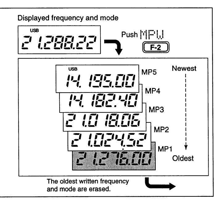
- ② Push [(F-2)MPW] to program the frequency into a memo pad.
When you write a 6th frequency and operating mode, the oldest written frequency and operating mode are automatically erased to make room for the new settings.
Note: Each memo pad must have its own unique combination of frequency and operating mode; memo pads having identical settings cannot be written.
Memo pads are convenient when you want to memorize a frequency and operating mode temporarily, such as when you find a DX station in a pile-up or when a station is busy for a long time and you want to temporarily search for other stations.
Use the transceiver's memo pads instead of relying on hastily scribbled notes that are easily misplaced.
• Calling up a frequency from a memo pad
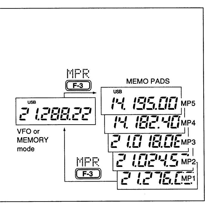
You can simply call up the desired frequency and operating mode of a memo pad by pushing [(F-3)
- •Make sure 51 is selected in advance.
- •Both VFO and memory modes can be use.
- The frequency and operating mode are called up, starting from the most recently written.
When you call up a frequency and an operating mode from memo pads with [(F-3)MPR], the previously displayed frequency and operating mode are automatically stored in a temporary pad. The frequency and operating mode in the temporary pad can be recalled by pushing [(F-3)MPR] one or more times.
Note: If you change the frequency or operating mode called up from a memo pad, the frequency and operating mode in the temporary pad are erased.
Scan types
■ Preparation
Channels
For programmed scan: Program scan edge frequencies into scan edge memory channels P1 and P2 (p. 33).
For memory scan: Program 2 or more memory channels except scan edge memory channels.
For memory select scan: Designate 2 or more memory channels as select memory channels—select a memory channel, then push [(F-2)SEL] in the S2 display (memory mode) to designate the channel as a select memory channel.
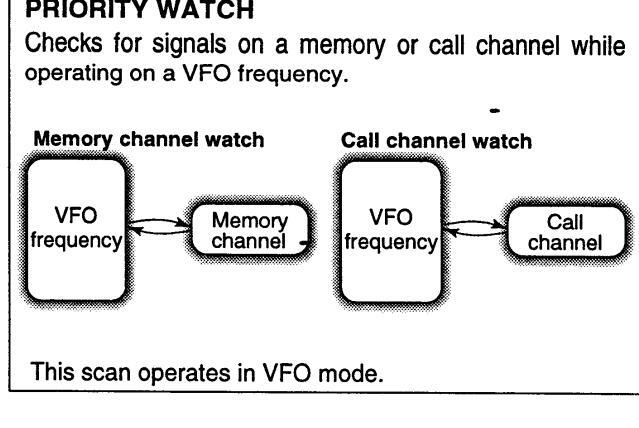
For priority watch: Program 1 memory channel to be watched.
•Scan resume ON/OFF
You can select the scan to resume or cancel when detecting a signal, in initial set mode, item 9. Scan resume ON/OFF must be set before operating a scan. See p. 46 for ON/OFF setting and scan resume condition details.
•Scan speed
Scan speed can be selected from 2 levels, high or low, in initial set mode. See p. 46 for details.
Squelch condition
|
SCAN
STARTS WITH |
PROGRAMMED
SCAN |
MEMORY SCANS
PRIORITY WATCH |
||
|---|---|---|---|---|
| SOUELCH |
The scan continues
until it is stopped manually, and does not pause even if it detects signals. |
Scan pauses on each
channel when the scan resume is ON; not applicable when OFF. |
||
| OPEN |
This is not applicable
when the scan resume is OFF and a programmable step (more than 1 kHz) is selected. |
|||
| Scan stops when deter | cting a signal. | |||
|
SQUELCH
CLOSED |
If you set scan resume ON in initial set mode,
the scan pauses for 10 sec. when detecting a signal, then resumes. When a signal disap- pears while scan is paused, scan resumes 2 sec. later. |
|||
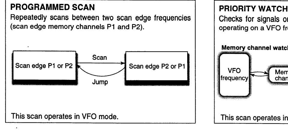
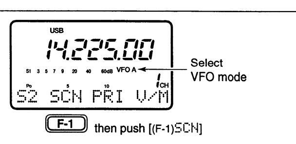
Programmed scan operation
- ① Select VFO mode.
- 2 Select the desired operating mode.
- •The operating mode can also be changed while scanning.
- ③ Set [SQL] open or closed.
- •See page a left for squelch condition.
- Select 52, then push [(F-1)SCN] to start the scan. Decimal point blinks while scanning.
- (5)When the scan detects a signal, the scan turns OFF, pauses or ignores it depending on the resume setting and the squelch condition.
- •During scan [TS] can be used only when resume is ON. © To cancel the scan push [(F-1)5CH].
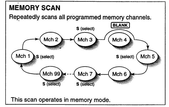
Memory scan operation
① Select memory mode.
- 2 Close the squelch with [SQL].
- ③ Select S2, then push [(F-1)SCN] to start the scan. Decimal point blinks while scanning.
- When the scan detects a signal, the scan stops or pauses depending on the resume setting.
- ⑤ To cancel the scan push [(F-1)5다].
Note: If the same frequencies are programmed into the scan edge memory channels P1 and P2, programmed scan does not start.
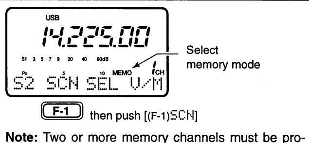
grammed for memory scan to start.
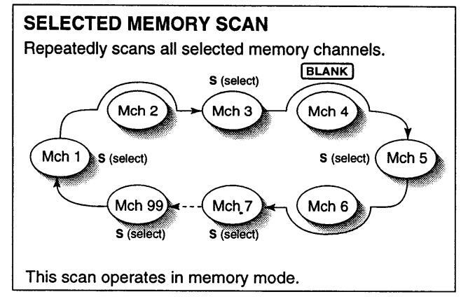
Select memory scan operation
- ① Select memory mode.
- @ Close the squelch with [SQL].
-
③ Select S2, then push [(F-1)SCH] to start the memory scan.
- Decimal point blinks while scanning.
- Push [(F-2)SEL] to change the memory scan to select memory scan.
- Push [(F-2)SEL] for 2 sec. to clear all select memory channels.
- (5) When the scan detects a signal, the scan stops or pauses depending on the resume setting.
- ⑥ To cancel the scan push [(F-1)SCH].
Priority watch
- ① Select VFO mode, then set a frequency.
- 2 Close the squelch with [SQL].
- ③ Set the desired memory channel as the watching channel.
- ④ Select S2, then push [(F-2)PRI] to start the watch. Decimal point blinks while scanning.
- S When the scan detects a signal, the scan pauses for 10 sec. or until the signal disappears, depending on the resume setting.
- © To cancel the scan push [(F-2)PRI].
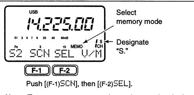
Note: Two or more memory channels must be designated as select memory channels for select memory scan to start.
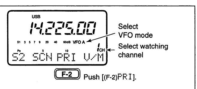
Note: The paused condition when detecting a signal differs depending on the scan resume condition. resume on: pauses for 10 sec. resume off: pauses until the signal disappears.
REMOTE JACK (CI-V) INFORMATION
♦ CI-V connection example
The transceiver can be connected through an optional CT-17 CI-V LEVEL CONVERTER to a personal computer equipped with an RS-232C port. The Icom Communication interface-V (CI-V) controls the following functions of the transceiver.
Up to four Icom CI-V transceivers or receivers can be connected to a personal computer equipped with an RS-232C port. See p. 48 for setting the CI-V condition using initial set mode.

♦ Data format
The CI-V system can be operated using the following data formats. Data formats differ according to command numbers. A data area is added for some commands.
CONTROLLER TO IC-706MKII
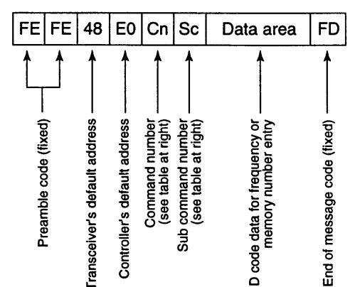
IC-706MKII TO CONTROLLER
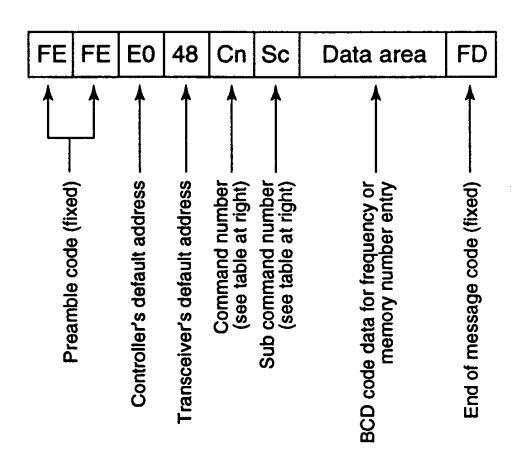
OK MESSAGE TO CONTROLLER
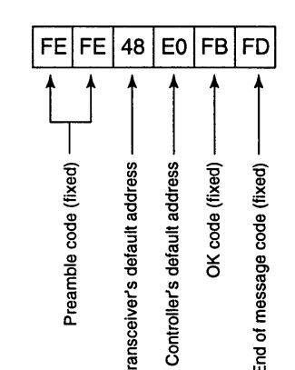
NG MESSAGE TO CONTROLLER
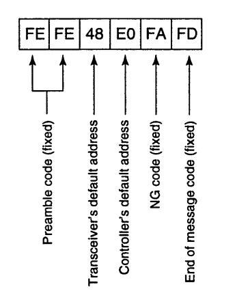
*1When wide or normal operation is available, add "00" for wide operation or "01" for normal operation; when normal or narrow operation is available, add "00" for normal operation or "01" for narrow operation; when wide, normal and narrow operation is available, add "00" for wide operation, "01"
COMMAND TABLE
| Description | Cn | Sc |
|---|---|---|
| Frequency control | 05 | Data |
| LSB | 00*1 | |
| USB | 01*1 | |
| Operating AM | 02*1 | |
| mode and CW | 06 | 03*1 |
| control RTTY | 04*1 | |
| FM | 05*1 | |
| WFM | 06* 1 | |
| VFO mode | - | |
| VFO A | 00 | |
| VFO B | 07 | 01 |
| A=B | A 0 | |
| A/B | B 0 | |
| Memory mode | 08 | |
| Memory selection | 00 | mc*2 |
| Memory write | 09 | |
| Memory to VFO | 0A | — |
| Memory clear | 0B | — |
| Scan stop | OF | 00 |
| Scan start | 01 | |
| Split OFF | OF | 00 |
| Split ON | 01 | |
| [TS] OFF (10 Hz step) | 00 | |
| [TS] ON | ||
| 100 Hz step | 01 | |
| 1 kHz step | 02 | |
| 5 kHz step | 03 | |
| 9 kHz step | 10 | 04 |
| 10 kHz step | 05 | |
| 12.5 kHz step | 06 | |
| 20 kHz step | 07 | |
| 25 kHz step | 1 | 08 |
| 1 |
tion and "02" for narrow operation.
*2Memory channel number (BCD) P1=0100, P2=0101, C=0102.
SET MODE
General
Set mode is used for programming infrequently changed values or conditions of functions. The IC-706MKII has 2 separate set modes: quick set mode and initial set mode.
♦ Quick set mode operation
(1) While power is ON, push [DISPLAY] for 2 sec.
- Quick set mode is selected and one of its items appears. •Quick set mode items vary depending on the operating mode (SSB, FM, etc.) selected.
- @Push [MENU] one or more times to select the desired item
IM-CH] or [▲]/[♥] can also be used.
- ③ Rotate the main dial to set the values or conditions for the selected item
- (4) Repeat steps (2) and (3) to set other items.
- ⑤ To exit quick set mode, push [DISPLAY] momentarilv.
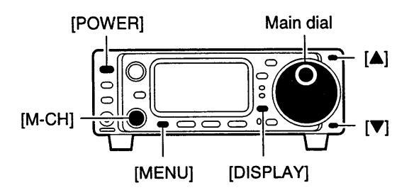
[DISPLAY EXAMPLE: QUICK SET MODE]
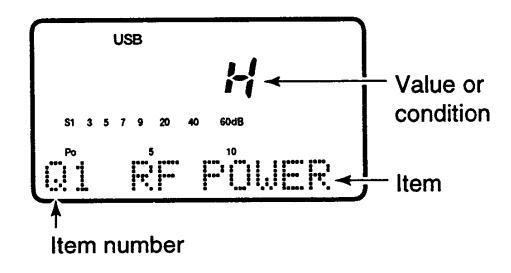
♦ Initial set mode operation
1 Push [POWER] for 2 sec. to turn power OFF. 2 While pushing [LOCK] push [POWER] to turn power
- ON.
- Initial set mode is selected and one of its items appears.
-
③ Push [MENU] one or more times to select the desired item
- [M-CH] or [▲]/[▼] can also be used.
- A Botate the main dial to set the values or conditions for the selected item.
- 5 Repeat steps 3 and 4 to set other items.
- 6 To exit initial set mode, push [POWER] for 2 sec. to turn power OFF.
- ⑦ Push [POWER] to turn power ON again.
- •The conditions selected in initial set mode are now effective.
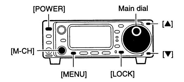
[DISPLAY EXAMPLE: INITIAL SET MODE]
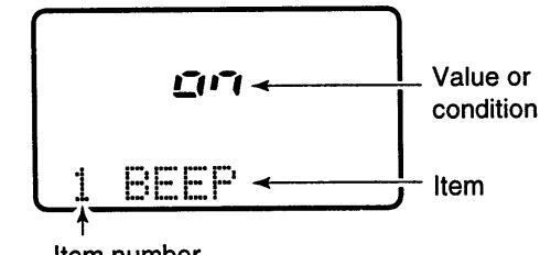
Item number
42
■ Quick set mode items
| na Mone Celert. | ||
|---|---|---|
|
This item is available in all modes, however, it only
appears after pushing the [MODE] key. This item allows you to simplify operation by inhibiting the selection of unneeded operating modes during nor- mal operation. For example if you are operating mobile and only plan on using FM and AM modes, use "MODE SELECT" to inhibit access to all other modes (SSB, CW, RTTY, WFM), thereby making selection of AM or FM quick and easy. |
הים |
The default is on for all operating
modes. To toggle an operating mode on or off, push (or push and hold) [MODE] one or more times until the desired mode is displayed, then rotate the main dial to set on or off. |
| This item adjusts the RF output power. The RF output power can be adjusted from L, 1 to 9 and H for indication, however, it can be adjusted continuously. | Н |
The default is H (maximum power).
Note that while adjusting the output power, the power meter is displayed automatically. |
| Г | The default is 5. | |
| This item adjusts microphone gain from 1 to 10 for indication, however, it can be adjusted continuously. | 2 | Note that while adjusting mic gain, the ALC meter is displayed automatically. |
| This item adjusts the CW pitch. CW pitch is adjustable from 300 to 900 Hz in 10 Hz steps. | The default is 600 Hz. | |
| RTTY | ||
| gled between 1275, 1615 and 2125 Hz. | 2 125 | The default is 2125 Hz. |
| 많을 보면浴 나는트귀Ƴ (SSB/AM/FM only) | ||
| This item adjusts the VOX (Voice-activated Transmit) delay time. The delay time can be adjusted from 0 to 2 sec. in 0.1 sec. units. | The default is 1.0 seconds. | |
| ା성송 BK─IN DELAY (CWonly) | ||
| This item adjusts break-in delay time for CW semi break-in operation. The delay time is selectable from 0 to 2 sec. in 0.1 sec. units. | The default is 1.0 seconds. | |
| `'l'lll. `l | ||
| 많은 KTTY SHIFT (RTTY only) | ||
|
This item adjusts the RTTY shift. There are 3 selec-
table values: 170, 200 and 425 Hz. |
The default is 170 Hz. |
7 SET MODE
|
Q 수 C 유로로 I E R 두 가 역 (SSB only)
This item adjusts the carrier frequency (BFO frequen- cy), allowing you to change the audio characteristics. Selectable values are -200 to +200 Hz in 10 Hz steps. |
USB | The default is 0 Hz. |
|---|---|---|
|
Q속 RTTY KEYING
(RTTY only)
This item adjusts the RTTY keying. Normal or reverse keying can be selected |
RITY |
The default is "n," normal.
Normal : key open=mark Reverse : key open=space |
|
이슈 문문T문 T이어E (FM only)
This item selects a subaudible tone for FM-T mode |
885 | The default is 88.5 Hz. |
This item selects a subaudible tone for FM-T mode operation to access a repeater. There are 50 tones available from 67.0 Hz to 254.1 Hz (see table at right). In addition, there is a 1750 Hz tone burst function
In addition, there is a 1750 Hz tone burst function available for European repeaters. When "1750" is selected, [(F-3)T이어] in 144 transmits a tone burst signal during transmission.
| Availa | able s | subauc | dible te | ones | Ur | nit: Hz | |||
|---|---|---|---|---|---|---|---|---|---|
| 67.0 | 79.9 | 94.8 | 110.9 | 131.8 | 156.7 | 171.3 | 186.2 | 203.5 | 229.1 |
| 69.3 | 82.5 | 97.4 | 114.8 | 136.5 | 159.8 | 173.8 | 189.9 | 206.5 | 233.6 |
| 71.9 | 85.4 | 100.0 | 118.8 | 141.3 | 162.2 | 177.3 | 192.8 | 210.7 | 241.8 |
| 74.4 | 88.5 | 103.5 | 123.0 | 146.2 | 165.5 | 179.9 | 196.6 | 218.1 | 250.3 |
| 77.0 | 91.5 | 107.2 | 127.3 | 151.4 | 167.9 | 183.5 | 199.5 | 225.7 | 254.1 |
| 04 CU PADDLE (CW only) · | ||
|---|---|---|
|
cw
M |
The default is "n," normal. |
|
TIME SOL (FM only)
This item adjusts sets a subaudible tone for tone squelch use. (the same subaudible tone frequencies as for repeater operation are available—see above). |
88.5 | The default is 88.5 Hz. | |
|---|---|---|---|
|
Q등 KEY SPEED (CW only)
This item adjusts the CW key speed. The key speed can be selected from 6 to 60 wpm. |
~~
20 |
The default is 20 wpm. |
06 RATIO (CW only)
This item adjusts the CW key ratio (or weight). The ratio can be selected from 2.8 to 4.5.
ЗÜ
and S-meter level.
■ Initial set mode items
| 4 m,mm,mm, | ||
|---|---|---|
| L EEE'. (confirmation beep) | ||
|
A beep sounds each time a switch is pushed to con-
firm it. This function can be turned OFF for silent operation. |
Confirmation beep ON (default) | Confirmation beep OFF |
| 2 BAND BEEP (band beep) | ||
| A beep sounds when an operating frequency enters | of F | |
| or exits a transmit frequency range. This functions independent of the confirmation beep setting (above). |
Band beep ON
(default) |
Band beep OFF |
| nFF | וחיב | |
|
matically turn the transceiver OFF after a specified
time of operation. This item can be set to 20 min., 40 min., 60 min., or OFF. |
Auto power OFF
deactivates. (default) |
Auto power OFF set to 20 min. |
| ···· | ||
| 즉 부도님K. 님니도냐 (peak hold) | ||
| When the peak hold function is ON, the highest acti- | o rr | |
| vated segment of the meter remains visible for 0.5 sec.; when OFF, the meter functions normally. |
Peak hold ON
(default) |
Peak hold OFF |
| $1111 $111, $111, $11, $1, $ | ||
| 그 드니다. L I 그러 I (display backlighting) | ||
| The function display backlighting can be set to high, | |- |/ | La |
| low of OFF to suit ambient lighting. | Display backlighting set to high (default). | Display backlighting set to low. |
| 6 SPEECH LANG (voice synthesizer langu | lage) | |
| When the optional UT-102 voice synthesizer unit is | EnLi | _// /-1 |
| Japanese as the language. | Voice synthesizer functions in English (default). |
Voice synthesizer functions
in Japanese. |
| When the optional UT-102 voice synthesizer unit is | ii i | ĹŨ |
| synthesizer output. | Voice synthesizer output is faster (default). |
Voice synthesizer output
is slower. |
| When an optional UT-102 SPEECH SYNTHESIZER UNIT | ||
| frequency/mode only, or both the frequency/mode |
Voice synthesizer reads out
both the frequency/mode |
Voice synthesizer reads out the frequency/mode only. |
the frequency/mode only.
and S-meter level (default).
carregar lock e acender radio
SET MODE 7
| 9 SCAN RESUME (scan resume) | ||
|
This item sets the scan resume function ON or OFF.
ON: scan resumes 10 sec. after stopping on a signal (or 2 sec. after a signal disappears); OFF: scan does not resume after stopping on a signal. For the priori- ty watch, setting to OFF pauses the watch until sig- nal disappears and scan resumes. |
Scan resume function is turned ON (default). | Scan resume function is turned OFF. |
|
10 SCAN SPEED (scan speed)
This item sets the rate at which channels or frequen- cies are scanned during scan operations. High or low can be selected. |
-
Scan speed is set to high (default). |
L C
Scan speed is set to low. |
|
11 UND SPEED (up/down speed)
This item sets the rate at which frequencies are scanned through when the [UP]/[DN] switches are pushed and held. High or low can be selected. |
I p/down speed is set to high (default). |
L
C
Up/down speed is set to lo |
|
12 A-TUME STRT (auto tuner start)
The optional AT-180 ANTENNA TUNER has an auto- matic start capability which starts tuning if the SWR is higher than 1.5–3. When "oFF" is selected, the tuner remains OFF even when the SWR is poor (1.5–3). When "on" is selected, automatic tune starts even when the tuner is turned OFF. |
TFF
Auto tune function OFF (default). Note: Even when "on" is does not start for the 50 M |
کیت
Auto tune function ON. s selected, automatic tur MHz band. |
|
13 FTT T니어E (PTT tune function)
When an optional AH-3 ANTENNA TUNER is connect- ed, tuning can be started automatically at the moment the PTT is pushed. 14 F F C C H (available memo pads) This item sets the number of memo pad channels available. 5 or 10 memo pads can be set. |
T
uning starts only when
[TUNER] is pushed (default). 5 5 memo pads are available (default). |
Tuning starts when pushing [PT
on a new frequency. |
|
15 QUICK SPLIT (quick split function)
When this item is set to ON, pushing [SPL] for 2 sec. sets the undisplayed VFO frequency to the displayed VFO frequency plus the split offset or duplex offset, and activates split operation. |
Lini
Quick split function ON (default). |
16 SPL OFFSET (split offset)
This item sets the offset (difference between transmit and receive frequencies) for the quick split function. Note that this setting is not valid in FM mode.
17 DUP OFFSET (duplex offset)
This item sets the offset in the same manner as above. However, this setting is used for FM only and is used to input the repeater offset for a desired band
18 SPLIT LOCK (split lock)
When this item is ON the main dial can be used to adjust the transmit frequency (XFC) even while the lock function is activated
19 OPT. FIL 1 (optional filter)
When an optional filter is installed, this selection is necessary, otherwise the filters cannot be selected. Selections available are FL-100, FL-101, FL-103, FI -223. FI -232 and none (default). See p. 22 for usable filters for each mode and see p. 50 for filter installation.
29 OPT. FIL 2 (optional filter)
When an optional filter is installed, this selection is necessary, otherwise the filters cannot be selected. Selections available are FL-100, FL-101, FL-103, FL-223, FL-232 and none (default). See p. 22 for usable filters for each mode and see p. 50 for filter installation
21 RF GAIN (RFgain)
When this item is set to ON, the [RF/SQL] control can be used as the [RF] gain control in USB/LSB, CW/CW-R and RTTY modes and as the [SQL] control in FM and AM modes. When this item is set to OFF, the control functions as the [SQL] control regardless of the operating mode selected.
22 위에 NB (Noise blanker in AM mode)
When this item is set to ON, the noise blanker function is available in AM mode. This is useful when communicating in AM mode (the noise blanker function should not be used when listening to regular AM broadcasts as it may degrade the received audio).
- -
Split offset is set to minus (--) 4000 kHz.
Split offset is set to plus (+) 4000 kHz
ייניוניי
(+) 4000 kHz
1-11-1
- יאממיי
Duplex offset is set to minus Duplex offset is set to plus (-) 4000 kHz.
-,F.F.
Split lock function OFF (default)
Split lock function ON
171171
No filters are selected (default)
F: -,7,77
FL-223 (for LSB/USB mode) is selected.
1-11-1
No filters are selected (default)
F: -777
FL-223 (for LSB/USB mode) is selected
-FF
The [RF/SQL] control functions as a squelch control (default)
171171
RF gain can be adjusted using the squelch control.
Note: RF gain does not function in WFM mode
(default)
Noise blanker available

Noise blanker not available
23 PIJR 이제 CHK (Power on check)
When this item is set to "on," the set output power is briefly displayed when turning power ON (RIT and auto power off settings are also displayed if activated); when turned "oFF," the display goes directly to frequency indication at power ON.
24 SUBDIAL (Subdial function)
When this item is set to "rit," pushing [RIT/SUB] turns the RIT function ON (lights red)—rotating [M-CH] changes the RIT frequency; when this item is set to "Freq," pushing [RIT/SUB] turns the sub dial function ON (lights green)—rotating [M-CH] changes the operating frequency. Note that in FM, WFM and AM modes, pushing [RIT/SUB] always selects the sub dial function (lights green), regardless of this setting.
21 CI-U ADDRES (CI-V address)
To distinguish equipment, each CI-V transceiver has its own Icom standard address in hexadecimal code. The IC-706MKII's address is 4EH.
When 2 or more IC-706MKII's are connected to an optional CT-17 CI-V LEVEL CONVERTER, rotate the main dial to select a different address for each IC-706MKII in the range 01H to 7FH.
26 CI-U BAUD (CI-V data rate)
This item sets the data transfer rate. When "Auto" is selected, the baud rate is automatically set according to the connected controller or remote controller.
_____________________________________
Transceive operation is possible with the IC-706MKII connected to other Icom HF transceivers or receivers. When "on" is selected, changing the frequency, operating mode, etc. on the IC-706MKII automatically changes those of connected transceivers (or receivers) and vice versa.
_____ ___ (CI-V operating frequency data length)
When connecting the IC-706MKII to the IC-735 for transceive operation, you must change the operating frequency data length to 4 bytes.
•This item MUST be set to "on" only when operating transceiver with the IC-735.
Power on check ON (default)
-, -
Pushing [RIT/SUB] selects the RIT function (default).
FrEq
Pushing [RIT/SUB] selects the sub dial function.
닉튼님
Address set to 4EH (default).
ПFН
Address set to 7FH.
Auto
Auto baud rate (default)
Transceive ON
יק ברק
aFF
171171
(default)
Frequency data set to 5 bytes (default).
ニー
Frequency data set to 4 bytes.
MAINTENANCE
Fuse replacement
8
If a fuse blows or the transceiver stops functioning, try to find the source of the problem, and replace the damaged fuse with a new, rated fuse.
Caution: Disconnect the DC power cable from the transceiver when changing a fuse.
The IC-706MKII has 2 types of fuses installed for transceiver protection.
•DC power cable fuses ...................................
CIRCUITRY FUSE REPLACEMENT
The 13.8 V DC from the DC power cable is applied to all units in the IC-706MKII, except for the power amplifier, through the circuitry fuse. This fuse is installed in the PA unit.
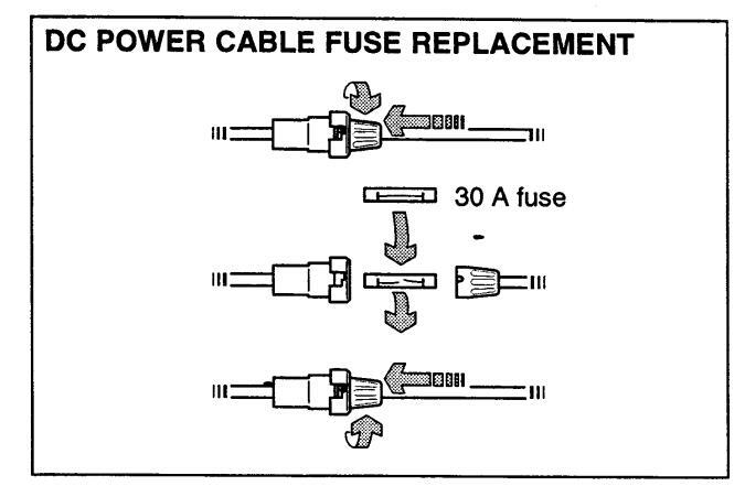
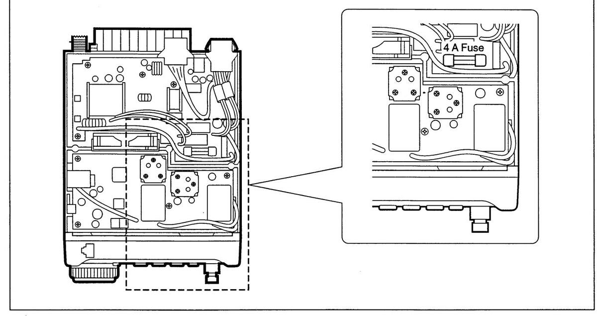
Memory backup
All of the CPU's memory is backed up by an EEP-ROM (Electronically-Erasable Programmable Read-Only Memory). All data you set, such as VFO, memory, set mode contents, etc. is stored in this EEP-ROM. There is no internal lithium battery.

■ Cleaning

If the transceiver becomes dusty or dirty, wipe it clean with a dry, soft cloth.
| No. | |
|---|---|
AVOID the use of strong chemical solvents such as thinner, benzine or alcohol to clean the transceiver. These may damage the transceiver's surfaces.
TROUBLESHOOTING
The following chart is designed to help you correct problems which are not equipment malfunctions.
If you are unable to locate the cause of a problem or solve it through the use of this chart, contact your nearest lcom Dealer or Service Center.
| PROBLEM | POSSIBLE CAUSE | SOLUTION | REF. | |
|---|---|---|---|---|
| ۲ |
Power does not come
on when the [POWER] switch is pushed. |
• DC power cable is improperly connected. |
|
p. 13 |
| OWER SUPPL | • Fuse is blown. |
• Check for the cause, then replace the fuse with a spare one.
(Fuses are installed in two places. One is installed in the DC power cable and the other is installed in the PA unit. |
p. 49 | |
| Ă |
|
• Check the battery voltage with the [POWER] pushed IN. | ||
| No sound comes from the speaker. | Volume level is set too low. |
|
p. 1 | |
|
Rotate [SQL] counterclockwise to open the squelch. |
p. 1
- |
||
|
|
— | ||
|
|
p. 12 | ||
|
p. 12 | |||
| Sensitivity is low. | • The antenna is not connected properly. | Reconnect to the antenna connector. | ||
| ECEIVE | • The antenna feed line is cut or shorted. | • Check the feed line and correct any improper conditions. | _ | |
| B | • The antenna for another band is selected. |
• Select an antenna suitable for the operating frequency.
Make sure that [ANT1] is used for frequencies less than 60 MHz and [ANT2] is used for frequencies of 60 MHz and above. |
p. 14 | |
| • The antenna is not properly tuned. | • Push [TUNE] to manually tune the antenna. |
pgs. 26,
27 |
||
| • The attenuator function is activated. | Push [ATT] to turn the function OFF. | p. 21 | ||
|
Receive audio is distort-
ed. |
• The operating mode is not selected correctly. | Select a suitable operating mode. | p. 19 | |
| • The [SHIFT] control is set off-center. | • Set [SHIFT] to the center position. | p. 20 | ||
| Receive signal is distort- | Noise blanker function is activated. | ● Push [HB] to turn the function OFF. | p. 21 | |
| eu with strong signals. | Preamp is activated. |
•Push [P.AMP] to turn the function
OFF |
p. 21 |
9 TROUBLESHOOTING
| PROBLEM | POSSIBLE CAUSE | SOLUTION | REF. | |
|---|---|---|---|---|
|
Transmitting is impossi-
ble. |
|
|
p. 17 | |
|
|
p. 28 | ||
| Output power is too low. |
|
• Set the output power in quick set mode. | p. 43 | |
|
|
p. 43 | ||
| • The antenna is not connected properly. | Reconnect the antenna connector. | - | ||
| • The antenna feed line is cut or shorted. |
|
— | ||
| • An antenna for another band is selected. |
|
p. 14 | ||
|
|
pgs. 26,
27 |
||
| LIN | No contact possible with | RIT function is activated. | Push RIT to turn the function OFF. | p. 20 |
| ANS | other stations. | Split function is activated. | Push [SPLIT] to turn the function OFF. | p. 28 |
| TR | Repeater cannot be ac- | Split function is not activated. | Push [SPLIT] to turn the function ON. | p. 28 |
| cessed. |
|
|
p. 17 | |
|
● Use [TÜN] to select FM-T. | p. 29 | ||
|
|
p. 44 | ||
|
• 1750 Hz tone burst cannot be trans-
mitted even when [TŪN] is pushed during transmission. |
|
p. 44 | ||
| Transmitted signals are | Microphone gain is set too high. | Set gain in quick set mode. | p. 43 | |
| distorted. |
• [COMP LEVEL] is rotated too far
clockwise with the speech compres- sor ON. |
|
p. 5 | |
| АҮ | Displayed frequency does not change proper- | The dial lock function is activated. |
• Push [LOCK] to deactivate the func-
tion. |
p. 2 |
| DISPL | ly. |
|
|
p. 15 |
| Programmed scan does not stop. | • Squelch is open. | • Set squelch to the threshold position. | p. 23 | |
| AN | Programmed scan does not start. |
•The same frequencies have been
programmed in scan edge memory channels P1 and P2. |
|
p. 40 |
| SC | Memory scan does not start. |
|
|
р. 36 |
| Memory select scan does not start. |
|
• Designate 2 or more memory chan-
nels as select channels for the scan. |
p. 40 |
OPTIONAL INSTALLATIONS/SETTINGS 10
Opening the transceiver case
To remove the transceiver case unscrew the 10 screws (5 in the top panel and 5 in the bottom panel) as shown in the diagram below.
Caution: Disconnect the DC power cable from the transceiver before performing any work on the transceiver.
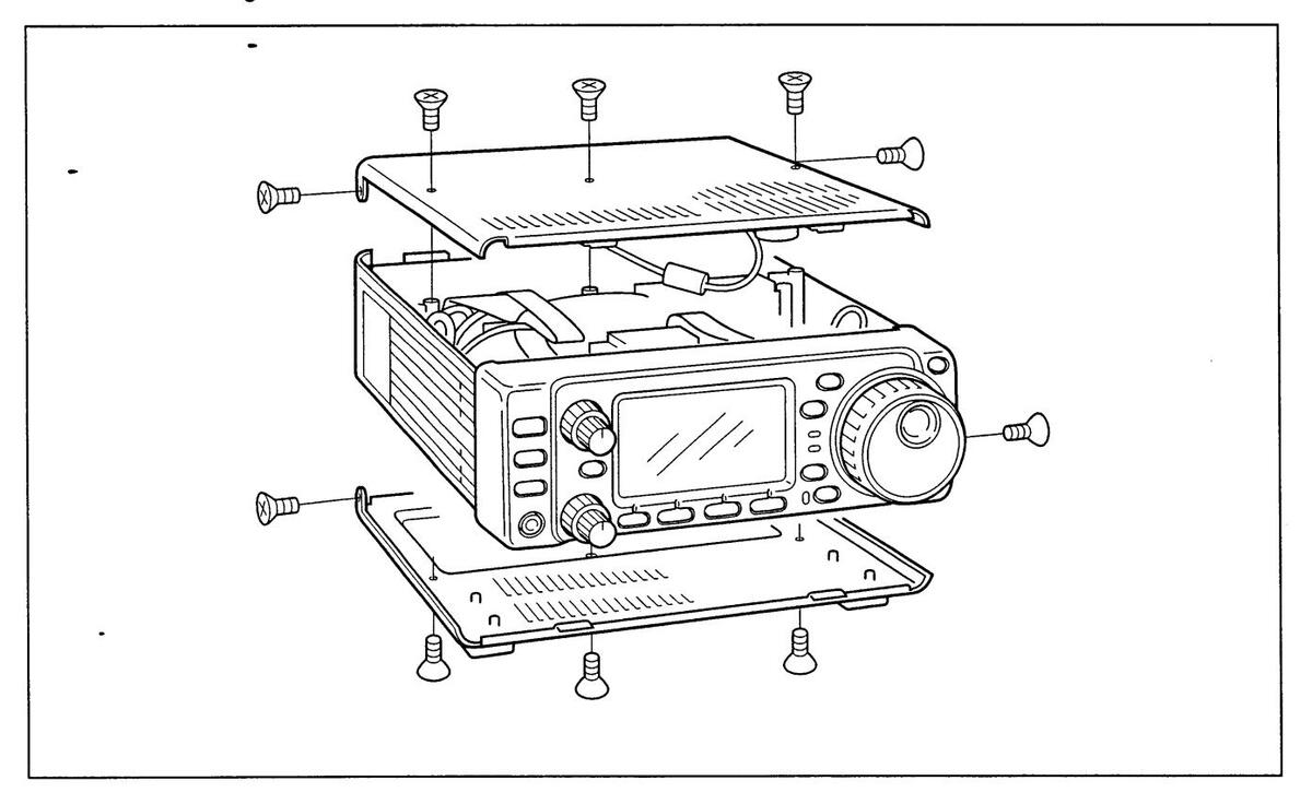
■ UT-102 VOICE SYNTHESIZER UNIT
The UT-102 announces the accessed band's frequency, mode, etc. (S-meter level can also be announced---p. 45) in a clear, electronically generated voice, in English (or Japanese).
① Remove the top cover as shown above.
- ②Connect the UT-102 as shown in the diagram at right (label side up).
- 3 Replace the top cover.
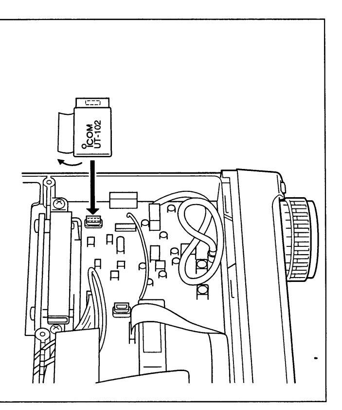
10 OPTIONAL INSTALLATIONS/SETTINGS
CR-502 HIGH-STABILITY CRYSTAL UNIT
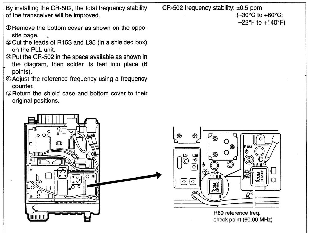
■IF filters
Several IF filters are available for the IC-706MKII. Choose a filter most appropriate to your operating needs.
Note: After filter installation, specify the installed filter using initial set mode (item 19). Otherwise, the installed filter will not function properly.
| FL-100 CW NARROW FILTER | 500 Hz/–6 dB |
|---|---|
| FL-101 CW NARROW FILTER | 250 Hz/6 dB |
| FL-103 SSB WIDE FILTER | 2.8 kHz/6 dB |
| FL-223 SSB NARROW FILTER | 1.9 kHz/–6 dB |
| FL-232 CW/RTTY NARROW FILTER | 350 Hz/–6 dB |
- ①Remove the top cover as shown on the previous page.
-
② Install the desired filter as shown in the diagram below.
- These filters can be installed in either direction.
- ③ Replace the top cover.
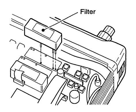
OPTIONAL INSTALLATIONS/SETTINGS 10
■ UT-86 TONE SQUELCH UNIT
The UT-86 TONE SQUELCH UNIT contains a subaudible tone encoder/decoder for tone squelch operation (see p. 30).
① Remove the top cover as shown on p. 53.
② Connect the UT-86 to pin 14 on the MAIN unit as shown in the diagram at right.
③ Replace the top cover.

■ AT-180 internal switch description
The optional AT-180 has 3 operating conditions for HF band operation. Select a suitable condition according to your antenna system.
① Remove the top cover of the AT-180.
2 Set the tuner switches to the desired positions according to the table below.
| SW | Position | Operation |
|---|---|---|
|
A
(default) |
The tuner operating condition is set by S2 described below. | |
| Image: Constraint of the second described below. THROUGH INHI The tuner tunes the antenna has 3:1 after tuning). ing is necessary frequency althou starts tuning where the second described below. B frequency althou starts tuning where the second described below. Image: the second described below. Image: the second described below. Image: the second described below. Image: the second described below. Image: the second described below. Image: the second described below. Image: the second described below. Image: the second described below. Image: the second described below. Image: the second described below. Image: the second described below. Image: the second described below. Image: the second described below. Image: the second described below. Image: the second described below. Image: the second described below. Image: the second described below. Image: the second described below. Image: the second described below. Image: the second described below. Image: the second described below. Image: the second described below. Image: the second described below. |
THROUGH INHIBIT
The tuner tunes the antenna even when the antenna has poor SWR (up to VSWR 3:1 after tuning). In this case, manual tun- ing is necessary each time you change the frequency although the tuner automatically starts tuning when the VSWR is higher than 3:1. This setting is called "through inhibit," however, the tuner is set to "through" if the VSWR is higher than 3:1 after tuning. |
|
| S2 | С |
TUNER SENSITIVE CONDITION
The tuner tunes each time you transmit (except SSB mode). Therefore, the lowest SWR is obtained at any given time. For SSB mode, the same condition as the "D" position. |
| D |
NORMAL CONDITION
The tuner tunes when the SWR is higher than 1.5:1. Therefore, the tuner activates only when tuning is necessary. |
|
•Specifications for the AT-180
| • Frequency coverage | : 1.9–54 MHz |
|
: 50 Ω |
|
: 120 W |
| Minimum tuning power | : 8 W |
|
: 16.7–150 Ω (HF band) |
| range | 20–125 Ω (50 MHz band) |
|
: Less than SWR 1.5:1 |
| Insertion loss |
: Less than 1.0 dB
(after tuning) |
| Power supply | : 13.8 V DC/1 A (supplied from |
| requirements | the transceiver's ACC socket) |
| • Dimensions (mm/in) | : 167(W)×58.6(H)×225(D) |
| 6%16(W)×25/17(H)×81/8(D) | |
| Weight | : 2.4 kg; 5 lb 4 oz |
|
s: coaxial cable (1 m), |
| ACC cable (DIN 13 pins) | |
•AT-180 inside top cover
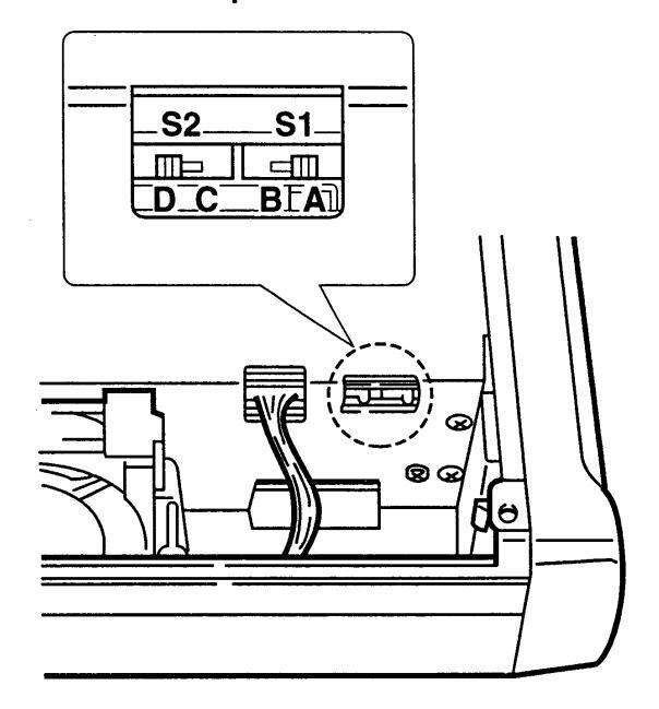
•Connector information for ACC(2) socket
![]()
|
PIN NOJ
NAME |
DESCRIPTION |
|---|---|
| ①8 V |
Regulated 8 V output.
(10 mA max.) |
| @ GND | Connects to ground. |
| ③ SEND |
Input/output pin.
Goes to ground when transmitting (20 mA max). When grounded, transmits. |
| @ BAND |
Band voltage output.
(Varies with amateur band; 0 to 8.0 V). |
| ⑤ ALC | ALC output voltage (-4 to 0 V/10 kΩ). |
| 6 NC | No connection. |
| ⑦ 13.8V | 13.8 V output when power is ON (1 A max). |
INTERNAL VIEWS
♦ Top view
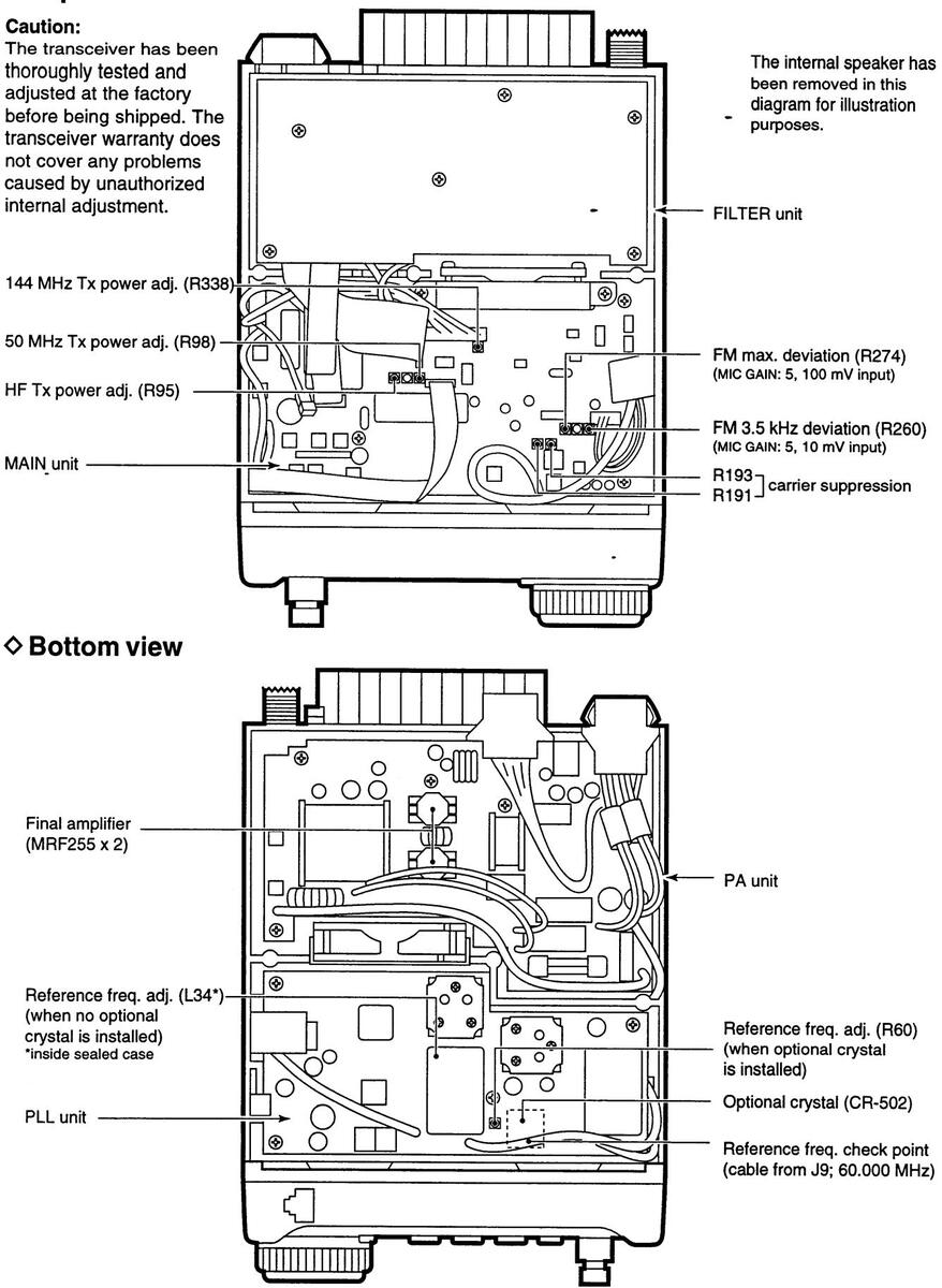
12 OPTIONS
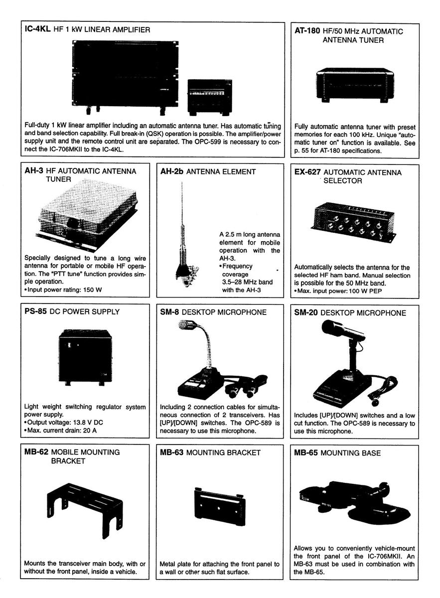
OPTIONS 12
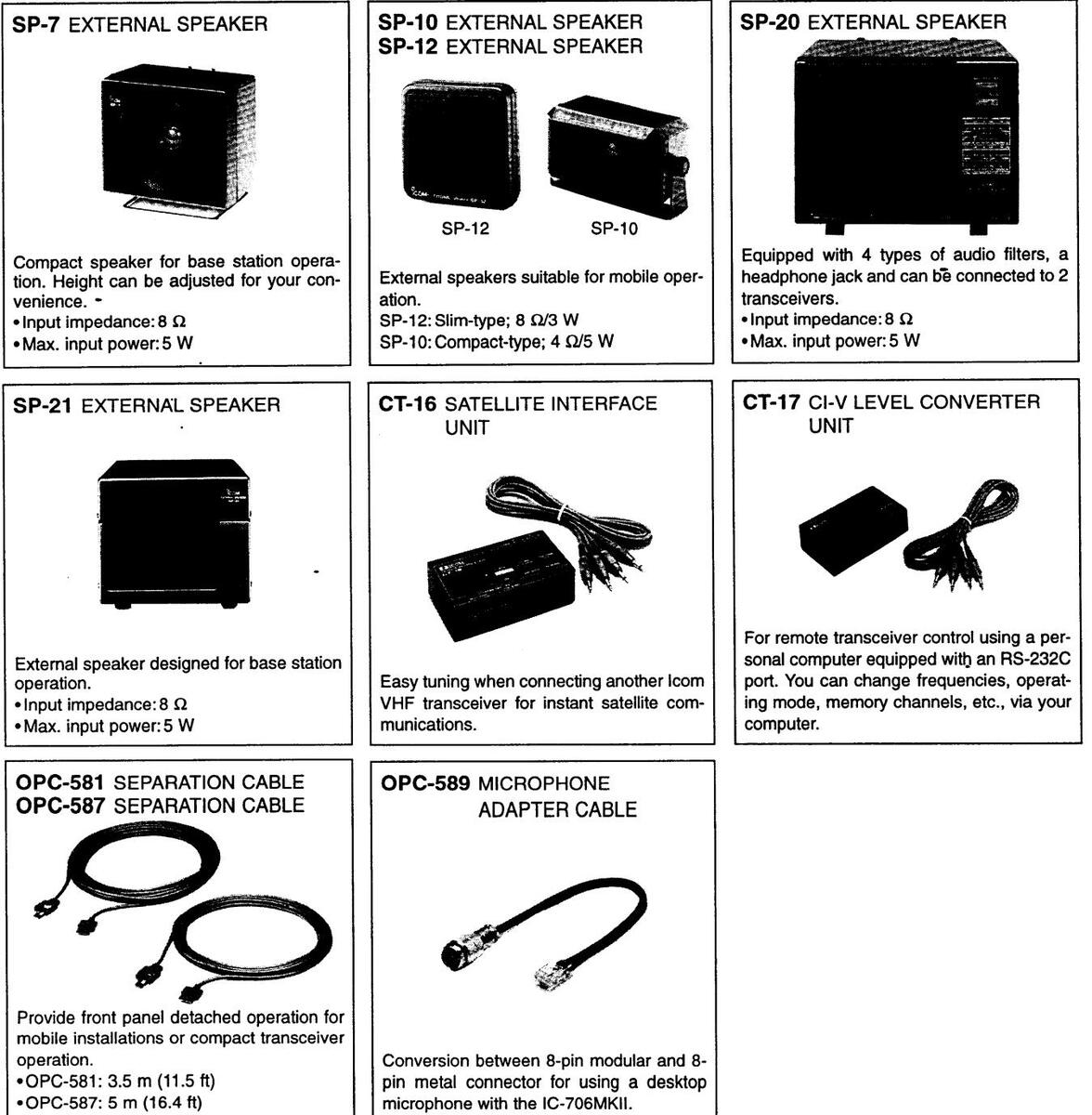
•OPC-587: 5 m (16.4 ft)
FL-100 CW NARROW FILTER (500 Hz/-6 dB) FL-101 CW NARROW FILTER (250 Hz/-6 dB) FL-103 SSB WIDE FILTER (2.8 kHz/-6 dB) FL-223 SSB NARROW FILTER (1.9 kHz/-6 dB) FL-232 CW/RTTY NARROW FILTER (350 Hz/-6 dB) Two of the above 5 filters can be installed at one time. CR-502 HIGH-STABILITY CRYSTAL UNIT Digitally controlled TCXO for improved frequency stability. Frequency stability: ±0.5 ppm (-30°C to +60°C; -22°F to +140°F) UT-86 TONE SQUELCH UNIT UT-102 VOICE SYNTHESIZER UNIT OPC-599 ADAPTER CABLE 13-pin, ACC connector to 7-pin + 8-pin ACC connector.
OPC-742 ACC 13-PIN CABLE Required when using both the AT-180 and a 2 m linear amplifier.
13 SPECIFICATIONS
GENERAL
|
: Receive | |
|---|---|---|
| 30 kHz-199.999999 MH | −lz* | |
| Transmit | ||
| 1.800- 1.99999 MH | Z* | |
| 3.500- 3.9999 MHz 1 | t | |
| 7.000- 7.300 MHz* | ||
| 10.100- 10.150 MHz | ||
| 14.000- 14.350 MHz | ||
| 18.068– 18.168 MHz | ||
| 21.000- 21.450 MHz | ||
| 24.890- 24.990 MHz | ||
| 28.000 - 29.700 MHz | ||
| • | 50.000- 54.000 MHz* | |
| 144.000 148.000 MHZ* | ||
| • Mada | Depending on version. | |
| ·wode | SSB, CW, AM, FM, WFM | , RITY |
| - Niemele - wie Constant | (WFM is for receive only) | |
| •Number of memory | : 102 (split memory: 99; scan | edges: 2; |
| channels . | call channel: 1) | |
|
: SO-239×2 (for HF/50 MH | z and |
| 144 MHz)/50 Ω | ||
| Usable temperature range | : -10°C to +60°C (+14°F to | +140°F) |
|
: Less than ±7 ppm from 1 | min. to |
| 60 min. after power ON. A | After that. | |
| rate of stability change is | less than | |
| ±1 ppm/hr. at +25°C (+77 | °F). | |
| Temperature fluctuations | 0°C to | |
| +50°C: +32°E to +122°E) | less than | |
| +5 ppm | ||
| Power supply | 13.8 V DC +15% (negativ | e around) |
| requirement | . 10.0 V DO 115/8 (negativ | e ground, |
| •Current drain | : Transmit | 20.4 |
| Popoino organished | 20 A | |
| (at 15.0 ¥ 20) | neceive squeiched | 1.0 A |
| 2.0 A | ||
| Dimensions | im | |
| 0%16(VV)×2%16(H)×7%8(D) | IN | |
| (projections not included) | ||
| • weight | : 2.45 kg (5 lb 6 oz) | |
| •CI-V connector | : 2-conductor 3.5 (d) mm ( 1 / 2 | ⁄s")/8 Ω |
|
• 13-nin |
•Output power
| 1.8–50 MHz | SSB, CW, FM, RTTY | 5–100 W |
|---|---|---|
| AM | 2–40 W | |
| 144 MHz | SSB, CW, FM, RTTY | 2-20 W |
| AM | 2–8 W | |
|
: | |
| SSB | Balanced modulation | |
| AM | Low level modulation | |
| FM | Variable reactance mo | odulation |
| • Spurious emissions | : Less than -50 dB (HF | -) |
| Less than60 dB (50 | , 144 MHz) | |
| • Carrier suppression | : More than 40 dB | |
|
: More than 50 dB | |
| Microphone connector | : 8-pin modular jack (60 | 0 Ω) |
|
: 3-conductor 6.35 (d) r | nm (¼") |
|
: 3-conductor 3.5 (d) m | m (¹⁄̀ෳ") ໌ |
RECEIVER
Receive system
SSB, CW, AM, RTTY Double-conversion superheterodyne WFM
| FM | I riple-conversion | superheterodyne |
|---|---|---|
|
ies: |
| MODE | 1st | 2nd | 3rd |
|---|---|---|---|
| SSB | 69.0115 MHz | 9.0115 MHz | |
| АМ | 69.0100 MHz | 9.0100 MHz | |
| CW | 69.0106 MHz | 9.0106 MHz | |
| RTTY | 69.0105 MHz | 9.0105 MHz | |
| FM | 69.0115 MHz | 9.0115 MHz | 455 kHz |
| FM-N | 69.0100 MHz | 9.0100 MHz | 455 kHz |
| WFM | 70.7000 MHz | 10.7000 MHz |
Sensitivity (pre-amp ON):
| •Sensitivity (pre-amp t | JN): |
|---|---|
| SSB/CW | 1.8–28* MHz |
| (for 10 dB S/N) | Less than 0.15 µV |
| 28–29.999 MHz | |
| Less than 0.15 uV | |
| 50–54 MHz | |
| less than 0.12 uV | |
| 144 – 148 MHz | |
| Less than 0.11 uV | |
| АМ | |
| (for 10 dB S/N) | |
| 50-54 MHZ | |
| 144–148 MHz | |
| F 14 | Less than 1.0 µV |
| FM | 28–29.999 MHz |
| (for 12 dB SINAD) | Less than 0.5 µV |
| 50–54 MHz | |
| Less than 0.25 µV | |
| 144–148 MHz | |
| Less than 0.18 µV | |
| WFM | 76–108 MHz |
| (for 12 dB SINAD) | Less than 10 µV |
| *Except 4–4.5 MHz | , 8–9 MHz. |
|
pre-amp ON) : |
| SSB | Less than 5.6 µV at threshold |
| FM | Less than 0.32 µV at threshold |
|
: |
| SSB, CW, RTTY | More than 3.0 kHz/–6 dB |
| Less than 4.8 kHz/-60 dB | |
| AM/FM-N | More than 8.0 kHz/–6 dB |
| Less than 30.0 kHz/-40 dB | |
| FM | More than 12.0 kHz/-6 dB |
| Less than 30.0 kHz/-60 dB | |
| *Without optional filter and with | |
| mid band selected. | |
| • Spurious and image | : More than 70 dB (except IF through |
| rejection ratio | on 50 MHz) |
| More than 60 dB (2 m FM mode) | |
| •Audio output power | · More than 2.0 W at 10% distortion |
| with an 8 Q load | |
| • BIT variable range | · +9 99 kHz max |
| •PHONES connector | "3-conductor 3.5 (d) mm (1/4")/8 O |
| •FXT SP connector | : 2-conductor 3.5 (d) mm (1/8)/0.52 |
| · |
MENU GUIDE 14
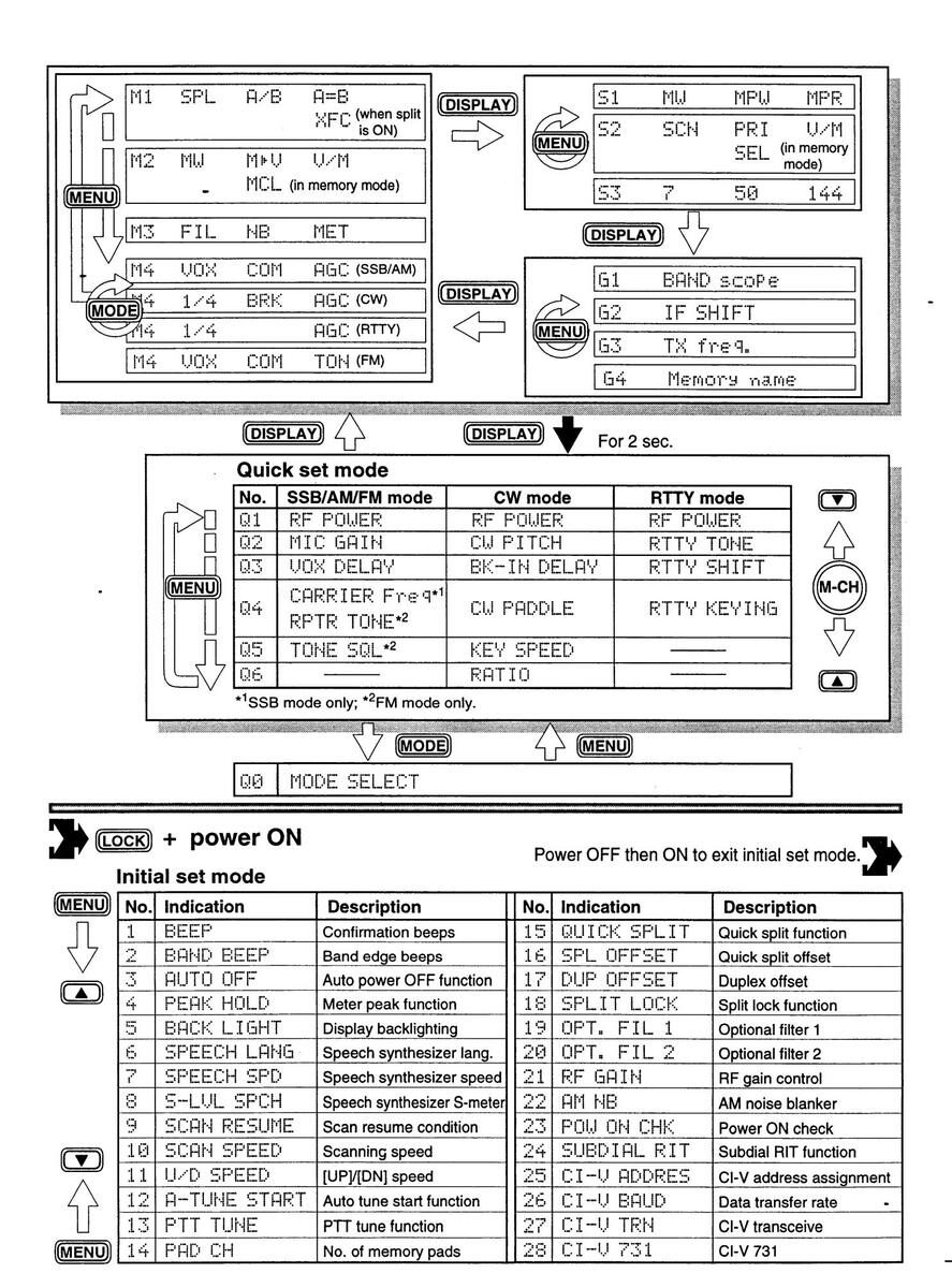
Count on us!


 Loading...