

Page 1

January 2000
This manual supports:
ThinkPad 600X (MT 2645)
ThinkPad 600X (MT 2646)
Page 2

Note
Before using this information and the product it
supports, be sure to read the general information
under “Notices” on page 78.
First Edition (January 2000)
The following paragraph does not apply to the United
Kingdom or any country where such provisions are
inconsistent with local law:
INTERNATIONAL BUSINESS MACHINES
CORPORATION PROVIDES THIS PUBLICATION “AS IS”
WITHOUT ANY WARRANTY OF ANY KIND, EITHER
EXPRESS OR IMPLIED, INCLUDING, BUT NOT LIMITED
TO, THE LIMITED WARRANTIES OF
MERCHANTABILITY OR FITNESS FOR A PARTICULAR
PURPOSE. Some states do not allow disclaimer or
express or implied warranties in certain transactions;
therefore, this statement may not apply to you.
This publication could include technical inaccuracies or
typographical errors. Changes are periodically made to
the information herein; these changes will be incorporated
in new editions of the publication. IBM may make
improvements or changes to the products or the programs
described in this publication at any time.
It is possible that this publication may contain references
to, or information about, IBM products (machines and
programs), programming, or services that are not
announced in your country. Such references or
information must not be construed to mean that IBM
intends to announce such IBM products, programming, or
services in your country.
Requests for technical information about IBM products
should be made to your IBM authorized dealer or your IBM
marketing representative.
Copyright International Business Machines
Corporation 2000. All rights reserved. Note to U.S.
Government Users – Documentation related to restricted
rights – Use, duplication, or disclosure is subject to
restrictions set forth in GSA ADP Schedule Contract with
IBM Corp.
Page 3

Contents
Read this first ................... 1
Related service information ............ 3
Reset switch . . . . . . . . . . . . . . . . . 3
Service Web site ............... 3
Passwords . . . . . . . . . . . . . . . . . . 3
Power management features .......... 5
Checkout guide . . . . . . . . . . . . . . . . . . 7
Testing the computer ............. 7
Detecting system information with PC-Doctor . . 9
Power system checkout ............ 9
Port replicator checkout ............ 12
Product overview . . . . . . . . . . . . . . . . . 13
Features . . . . . . . . . . . . . . . . . . . 13
Status indicators . . . . . . . . . . . . . . . . 15
Fn key combinations .............. 16
Symptom-to-FRU error messages ......... 17
How to use error messages .......... 17
How to diagnose multiple FRUs ........ 17
Symptom-to-FRU index . . . . . . . . . . . . 17
Numeric error codes .............. 18
Beep symptoms . . . . . . . . . . . . . . . . 23
Audio-related symptoms . . . . . . . . . . . . 24
CD-ROM-related symptoms . . . . . . . . . . 24
Function-related symptoms . . . . . . . . . . . 27
Indicator-related symptoms . . . . . . . . . . . 27
Infrared-related symptoms . . . . . . . . . . . 28
Keyboard- or TrackPoint-related symptoms . . . 28
LCD-related symptoms . . . . . . . . . . . . . 29
Modem-related symptoms . . . . . . . . . . . 29
PC Card-related symptoms ........... 30
Peripheral-device-related symptoms . . . . . . . 30
Power-related symptoms . . . . . . . . . . . . 31
Other symptoms . . . . . . . . . . . . . . . . 31
Intermittent problems . . . . . . . . . . . . . . 31
Undetermined problems . . . . . . . . . . . . 31
FRU replacement notices ............. 33
Screw notices . . . . . . . . . . . . . . . . . 33
Retaining serial numbers ............ 34
FRU removals and replacements ......... 36
1010 Backup battery . . . . . . . . . . . . . 38
1020 DIMM . . . . . . . . . . . . . . . . . . 39
1025 Modem card . . . . . . . . . . . . . . . 40
1030 Battery pack . . . . . . . . . . . . . . . 41
1040 Hard disk drive ............. 42
1050 UltraslimBay device . . . . . . . . . . . 43
1060 Keyboard assembly . . . . . . . . . . . 44
1070 Keyboard . . . . . . . . . . . . . . . . 47
1080 Speakers . . . . . . . . . . . . . . . . 48
1085 Speaker cable . . . . . . . . . . . . . . 50
1090 LCD assembly . . . . . . . . . . . . . . 51
Copyright IBM Corp. 2000 iii
Page 4

1100 PC Card slot assembly .......... 52
1110 Asset ID RF adapter kit ......... 53
1120 Sub card . . . . . . . . . . . . . . . . 54
1130 Guide rail, microphone cable, or TV Out card 55
1140 CPU card and fan ............ 56
1150 Modem cable assembly ......... 58
1160 System board . . . . . . . . . . . . . . 60
2010 LCD front cover ............. 61
2020 LCD Hinges and cables ......... 62
2030 Inverter card . . . . . . . . . . . . . . 64
Locations . . . . . . . . . . . . . . . . . . . . . 65
Front view . . . . . . . . . . . . . . . . . . . 65
Rear view . . . . . . . . . . . . . . . . . . . 66
Bottom view . . . . . . . . . . . . . . . . . . 67
Password pads . . . . . . . . . . . . . . . . 68
Parts list . . . . . . . . . . . . . . . . . . . . . 69
Keyboard . . . . . . . . . . . . . . . . . . . 72
LCDFRU . . . . . . . . . . . . . . . . . . . 73
Common Parts List .............. 76
Notices . . . . . . . . . . . . . . . . . . . . . . 78
Trademarks . . . . . . . . . . . . . . . . . . 78
iv ThinkPad 600X Hardware Maintenance Manual
Page 5

Read this first
Read this first
Before you go to the checkout guide, be sure to read this
section.
Important notes
Only certified trained personnel should
service the computer.
Read the entire FRU removal and replacement
page before replacing any FRU.
Use new nylon-coated screws when you
replace FRUs.
Be extremely careful during such write
operations as copying, saving, or formatting.
Drives in the computer that you are servicing
might have been rearranged, or the drive startup
sequence might have been altered. If you select
an incorrect drive, data or programs might be
overwritten.
Replace FRUs only for the correct model.
When you replace a FRU, make sure the model
of the machine and the FRU part number are
correct by referring to the FRU parts list.
A FRU should not be replaced because of a
single, unreproducible failure. Single failures
can occur for a variety of reasons that have
nothing to do with a hardware defect, such as
cosmic radiation, electrostatic discharge, or
software errors. Consider replacing a FRU only
when a problem recurs. If this is suspected,
clear the error log and run the test again. Do not
replace any FRUs if log errors do not reappear.
Be careful not to replace a nondefective FRU.
What to do first: When you do return a FRU, you
must include the following information in the parts
exchange form or parts return form that you attach to it:
1. Name and phone number of servicer
2. Date of service
3. Date on which the machine failed
4. Date of purchase
5. Failure symptoms, error codes appearing on the
display, and beep symptoms
6. Procedure index and page number in which the
failing FRU was detected
7. Failing FRU name and part number
8. Machine type, model number, and serial number
9. Customer's name and address
Before checking problems with the computer, determine
whether the damage is covered under the warranty by
referring to the following:
1
Page 6

Read this first
Note for warranty: During the warranty period, the
customer may be responsible for repair costs if the
computer damage was caused by misuse,
accident, modification, unsuitable physical or
operating environment, or improper maintenance by
the customer. The following list provides some
common items that are not covered under warranty
and some symptoms that might indicate that the
system was subjected to stress beyond normal
use.
The following is not covered under warranty:
LCD panel cracked from the application of
excessive force or from being dropped.
Scratched (cosmetic) parts.
Cracked or broken plastic parts, broken latches,
broken pins, or broken connectors caused by
excessive force.
Damage caused by liquid spilled into the system.
Damage caused by the improper insertion of a
PC Card or the installation of an incompatible
card.
Damage caused by foreign material in the
diskette drive.
Diskette drive damage caused by pressure on
the diskette drive cover or by the insertion of a
diskette with multiple labels.
Damaged or bent diskette eject button.
Fuses blown by attachment of a nonsupported
device.
Forgotten computer password (making the
computer unusable).
The following symptoms might indicate damage
caused by nonwarranted activities:
Missing parts might be a symptom of
unauthorized service or modification.
HDD spindles can become noisy from being
subjected to excessive force or from being
dropped.
I9990303 errors can be caused by exposure to
strong magnetic fields.
2 ThinkPad 600X Hardware Maintenance Manual
Page 7

Related service information
Related service information
This section provides information about the following:
“Reset switch”
“Service Web site”
“Passwords”
Power management features
Reset switch
The Reset switch resets the system (regardless of the
microcode status) and forces the power off. Use this
pushbutton to power off when power is not completely off
or the microcode is in a hung state. For its location, see
“Rear view” on page 66.
Service Web site
When the latest maintenance diskette and the system
program service diskette are available, a notice will be
posted on http://pccbbs.raleigh.ibm.com/
Passwords
As many as three passwords may be needed for any
ThinkPad computers: the power-on password (POP), the
hard disk password (HDP), and the supervisor password
(PAP).
When the power-on password (POP), the hard disk
password (HDP), or the supervisor password (PAP) is
used, the following situations may occur:
If the PAP is used, the HDP is enabled automatically, but
no HDP prompt appears. The HDP is set the same as the
PAP.
If the POP is the same as the HDP
prompt appears, but the HDP prompt does not
appear.
If the POP is not the same as the HDP
prompts appear.
If a ThinkPad computer has an extra bay, it can support
more than two HDPs. Then the following situations will
occure:
POP
If the
or HDP-2), a POP prompt appears. The passwords
are different.
If the
(HDP-1 or HDP-2), both prompts appear.
If the
automatically enabled, but the HDP prompt does not
appear. The HDP-1 or the HDP-2 are then set to the
same password as the PAP.
is the same as one of the
POP
is not the same as either of the
PAP
is used, the
HDP-1
or the
, the POP
, both
HDPs
(HDP-1
HDPs
HDP-2
is
3
Page 8

Related service information
Supervisor and hard disk passwords: The
supervisor password (PAP) and the hard disk password
(HDP) are security features that are used to protect the
system and the hard disk data from unauthorized access.
No overriding capability is provided. If only a hard disk
password is set, you must get the password from its owner
in order to run diagnostic tests and perform service. If
both the supervisor password and the hard disk password
are set, you can enter Easy-Setup by pressing the Enter
key or by entering the power-on password at the
supervisor password prompt. In this case, the Password,
Start up, Network, and Initialize or Asset ID (for some
models) icons cannot be selected.
Note: The supervisor password and the hard disk
password cannot be replaced if they are forgotten.
If the customer forgets the supervisor password,
the system board must be replaced. If the
customer forgets the hard disk password, the hard
disk drive must be replaced.
How to remove the power-on passwords:
If only the power-on password is set, do the following to
remove it:
1. Turn off the computer.
2. Remove the DIMM cover from the bottom of the
computer.
3. Short-circuit the two password pads or put the jumper
on the pins.
For the location of the password pads or the jumper,
see “Password pads” on page 68.
4. Turn on the computer and wait until the POST ends.
After the POST ends, the password prompt does not
appear. The power-on password has been removed.
5. Reinstall the DIMM cover.
If both the power-on password and the supervisor
password are set, do the following to remove them:
1. Power on the computer by pressing and holding F1.
2. Enter the supervisor password. The Easy-Setup
menu appears.
3. Click the Password icon.
4. Click the Power on icon.
5. Enter the supervisor password, and press the Space
bar.
6. Press Enter twice.
7. Click Exit; then click Restart.
The power-on password has been removed.
4 ThinkPad 600X Hardware Maintenance Manual
Page 9

Related service information
Power management features
To reduce power consumption, the computer has three
power management modes: standby, suspend, and
hibernation.
Standby mode: In standby mode, the following
occurs:
The LCD backlight turns off.
The hard disk drive motor stops.
The speaker is muted.
Note: Standby mode in Windows 98 is called
mode
in Windows 95.
To enter standby mode, press Fn + F3. To end standby
mode and resume normal operation, press any key.
Suspend mode: When the computer enters suspend
mode, the following events occur in addition to what occurs
in standby mode:
The LCD is powered off.
The hard disk drive is powered off.
The CPU stops.
Suspend mode in Windows 95 is called
Windows 98.
You can cause the computer to enter suspend mode by
doing any of the following:
Press Fn + F4.
Close the LCD cover. (To prevent the computer from
entering suspend mode when the LCD is closed, click
Will not suspend even if LCD is closed in the
Power Management Properties window. Then only
the LCD turns off.)
Select the Suspend button in the Fuel Gauge
program.
In certain circumstances, the computer goes into suspend
mode automatically:
If a “suspend time” has been set on the timer, and the
user does not do any operation with the keyboard, the
TrackPoint, the hard disk, the parallel connector, or
the diskette drive within the time set.
If the ac adapter is plugged in.
If the battery indicator blinks orange, indicating that
the battery power is low. (Alternatively, if Hibernate
when battery becomes low has been selected in the
“Power Management Properties” window, the
computer goes into hibernation mode.)
Note: Even if you don't set the low-battery alarm, the
charge indicator lets you know that the battery is
low, and then the ThinkPad automatically enters
the power-saving mode. This default low-battery
suspend
standby mode
in
5
Page 10

Related service information
behavior is independent of the operating system.
So, if you have set the low-battery alarm, the
computer may not do what you specified. It
chooses either your setting or the default setting,
whichever is appropriate.
Any one of the following events causes the computer to
resume operation from suspend mode:
The Fn key is pressed.
The LCD cover is opened.
The ring indicator (RI) is signaled by a serial device
or a PC Card device.
The power switch is turned on.
The resume timer is set. In Windows 98, the
Scheduled Tasks setting has priority over the
Resume on timer selection in the “Power
Management Properties” window.
Note: The computer does not accept any input
immediately after it enters suspend mode.
Therefore, wait a few seconds before taking
any action to reenter operation mode.
Hibernation mode
Note for the Windows NT
A Windows NT user cannot create a hibernation file in
a Windows NT system that uses the NTFS format
system, the Windows NT default format. If you want
to use hibernation mode, you should reinstall Windows
NT with a FAT format system.
In hibernation mode, the following occurs:
The system status, RAM, VRAM, and setup data are
stored on the hard disk.
The system is powered off.
Notes
1. In the ThinkPad Configuration program, the
computer can be set to suspend/hibernate
while docked.
2. The computer cannot enter hibernation mode
when it is powered with ac power and a
communication PC Card is used.
Any one of the following events causes the computer to
enter hibernation mode:
The Fn + F12 keys are pressed.
The Hibernation button is selected in the Fuel-Gauge
program.
The power switch is turned off and the mode is set to
Power switch mode [Hibernation].
6 ThinkPad 600X Hardware Maintenance Manual
Page 11

Checkout guide
The timer conditions are satisfied in suspend mode
(for operating systems other than Windows 98).
A critically low battery condition occurs and mode is
set to Hibernate when battery becomes low.
When the power is turned on, the computer leaves
hibernation mode and resumes operation. The hibernation
file in the boot record on the hard disk drive is read, and
system status is restored from the hard disk drive.
Checkout guide
Use the following procedures as a guide in identifying and
correcting problems with the ThinkPad computer.
Note: The diagnostic tests are intended to test only IBM
products. The use of non-IBM products, prototype
cards, or modified options can lead to false
indications of errors and invalid system responses.
1. Identify the failing symptoms in as much detail as
possible.
2. Verify the symptoms. Try to re-create the failure by
running the diagnostic test or by repeating the
operation.
Testing the computer
The ThinkPad computer has a test program called
PC-Doctor DOS (hereafter called
detect errors by running the diagnostics test included in
PC-Doctor. This section is an overview of the procedure.
For details that depend on model-unique functions, refer to
“Product overview” on page 13.
For some possible configurations of the computer,
PC-Doctor might not run correctly. To avoid this problem,
you need to initialize the computer setup by Easy-Setup
before you run PC-Doctor. In the Easy-Setup screen, click
Config and Initialize.
Note: When you initialize the computer configuration,
some devices are disabled, such as the serial port.
If you test one of these devices, you need to
enable it by using PS2.EXE.
PC-Doctor does not support the test for the device in the
SelectaDock docking station.
You can test the device in the docking station with an
advanced test in Easy-Setup that is supported by the
ThinkPad 600, 600E, or 770x series.
To run such a test,
Remove a device from the bay of the docking station
and install it in the bay of the 600 or 600E computer.
Then start Easy-Setup.
PC-Doctor
). You can
7
Page 12

Checkout guide
Dock the 770 series computer to the docking station.
Then start Easy-Setup.
To run the test, do as follows:
Note: In the following procedure, you can select an item
not only with the arrow keys, but also with the
TrackPoint. Instead of pressing Enter, click the left
button.
1. Insert the PC-Doctor disk into the diskette drive; then
power on the computer.
If the computer cannot be powered on, go to “Power
system checkout” on page 9, and check the power
sources.
If an error code appears, go to “Symptom-to-FRU
error messages” on page 17.
In the first screen, select the model and press Enter.
Follow the instructions on the screen.
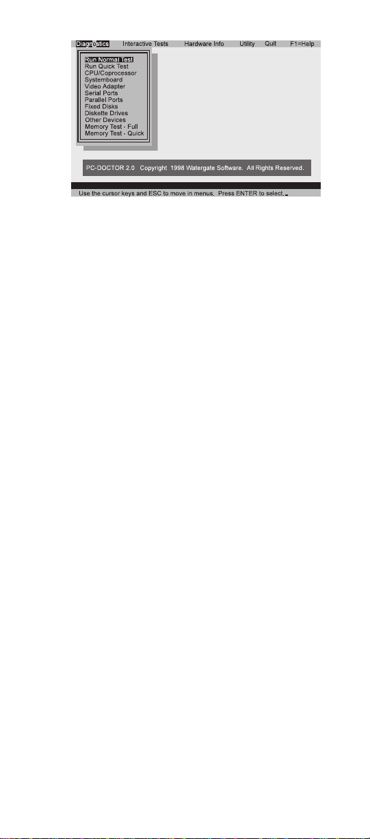
2. The PC-Doctor main panel appears.
3. Select Diagnostics with the arrow keys, and press
Enter.
A pull-down menu appears. (Its exact form depends
on the model.)
The options on the test menu are as follows:
Diagnostics Interactive Tests
Run Normal Test
Run Quick Test
CPU/Coprocessor
Systemboard
Video Adapter
Serial Ports
Fixed Disks
Diskette Drives
Other Devices
Memory Test – Full
Memory Test –
Quick
Notes:
In the Keyboard test in Interactive Tests, the
Fn key is scanned only once. Each key should
be held down for at least 2 seconds; otherwise, it
cannot be sensed.
Sound Card is not recognized in the Hardware
Info.
Keyboard
Video
Internal Speaker
Mouse
Joystick
Diskette
System Load
CD-ROM/DVD
Stereo Speaker
8 ThinkPad 600X Hardware Maintenance Manual
Page 13
Checkout guide
4. Run the applicable function test.
5. Follow the instructions on the screen. If there is a
problem, PC-Doctor shows some messages.
6. To exit the test, select Quit — Exit Diag.
To cancel the test, press Esc.
Detecting system information with
PC-Doctor
PC-Doctor can detect the following system information:
Hardware Info:
System Configuration
Memory Contents
Physical Disk Driver
Logical Disk Driver
VGA Information
IDE Drive Info
PCI Information
PNPISA Info
SMBIOS Info
FRU Info
Utility:
Run External Tests
Surface Scan Hard Disk
Benchmark System
DOS Shell
Tech Support Form
Battery Rundown
View Test Log
Print Log
Save Log
Full Erase Hard Drive
Quick Erase Hard Drive
Power system checkout
To verify the symptom of a problem, do the following:
1. Power off the computer.
2. Remove the battery pack.
3. Connect the ac adapter.
9
Page 14
Checkout guide
4. Check that power is supplied when you power on the
computer.
5. Power off the computer.
6. Disconnect the ac adapter and install the charged
battery pack.
7. Check that power is supplied by the battery pack
when you power on the computer.
If you suspect a power problem, see the appropriate one
of the following power supply checkouts:
“Checking the ac adapter”
“Checking operational charging”
“Checking the battery pack” on page 11
“Checking the backup battery” on page 12
Checking the ac adapter: You are here because
the computer fails only when the ac adapter is used:
If the power problem occurs only when the port
replicator is used, replace the port replicator.
If the power-on indicator does not turn on, check the
power cord of the ac adapter for correct continuity
and installation.
If the computer does not charge during operation, go
to “Checking operational charging.”
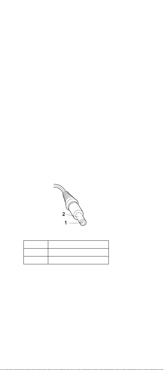
1. Unplug the ac adapter cable from the computer and
measure the output voltage at the plug of the ac
adapter cable. See the following figure:
(16 - 10 V)
Pin Voltage (V dc)
1 +15.5 to +17.0
2 Ground
If the voltage is not correct, replace the ac adapter.
If the voltage is acceptable, do the following:
Replace the system board.
If the problem persists, go to “Product overview”
on page 13.
Note: Noise from the ac adapter does not always indicate
a defect.
Checking operational charging: To check
operational charging, use a discharged battery pack or a
battery pack that has less than 50% of the total power
remaining when installed in the computer.
10 ThinkPad 600X Hardware Maintenance Manual
Page 15
Checkout guide
Perform operational charging. If the battery status
indicator or icon does not turn on, remove the battery pack
and let it return to room temperature. Reinstall the battery
pack. If the charge indicator or icon still does not turn on,
replace the battery pack.
If the charge indicator still does not turn on, replace the
system board. Then reinstall the battery pack. If the
reinstalled battery pack is not charged, go to the next
section.
Checking the battery pack: Battery charging
does not start until the Fuel Gauge shows that less than
95% of the total power remains; under this condition the
battery pack can charge to 100% of its capacity. This
protects the battery pack from being overcharged or from
having a shortened life.
Note: The battery pack might not be able to charge when
it is hot. In that case, remove it from the computer
and leave it at room temperature for a while. After
it cools down, reinstall and recharge it.
Do the following:
1. Power off the computer.
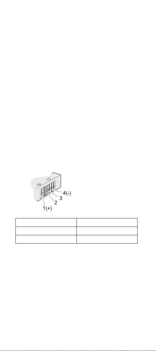
2. Remove the battery pack and measure the voltage
between battery terminals 1 (+) and 4 (−). See the
following figure:
Terminal Voltage (V dc)
1 + 0 to + 12.6
4 Ground (−)
3. If the voltage is less than +11.0 V dc, the battery pack
has been discharged. Recharge the battery pack.
Note: It takes at least 3 hours to recharge the
battery pack.
If the voltage is still less than +11.0 V dc after
recharging, replace the battery.
4. If the voltage is more than +11.0 V dc, measure the
resistance between battery terminals 3 and 4. The
resistance must be 4 to 30 K ohm.
If the resistance is not correct, replace the battery
pack. If the resistance is correct, replace the system
board.
11
Page 16
Checkout guide
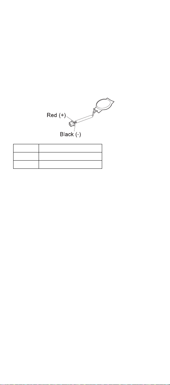
Checking the backup battery: Do the following:
1. Power off the computer, and unplug the ac adapter
from it.
2. Turn the computer upside down.
3. Remove the backup battery
Note: Removing the backup battery will cause loss
of configuration data unless the battery pack
is installed and operational.
(see “Checking the battery pack” on page 11).
4. Measure the voltage of the backup battery. See the
following figure.
Wire Voltage (V dc)
Red +2.5 to +3.2
Black Ground
If the voltage is correct, replace the system board.
If the voltage is not correct, replace the backup
battery.
If the backup battery discharges quickly after
replacement, replace the system board.
Port replicator checkout
Use the following procedure to isolate a port replicator
problem. The port replicator attaches to the system
expansion connector at the rear of the computer:
1. Power off the computer.
2. Remove the failing devices from the port replicator.
3. Unplug the AC Adapter from the port replicator, if it is
attached.
4. Remove the port replicator from the computer.
5. Reconnect the failing device directly to the computer.
(If another device is already connected to the
computer, remove it first.)
6. Go to “Testing the computer” on page 7 and run the
diagnostics.
7. If the advanced diagnostic device test does not find
an error, suspect a problem with the port replicator.
8. Power off the computer, and reconnect the port
replicator.
9. Power on the computer, and run the following
advanced diagnostic tests:
Serial port test with the wrap plug installed on
the port replicator
12 ThinkPad 600X Hardware Maintenance Manual
Page 17

Product overview
Universal serial bus test with the USB parallel
test cable
Parallel port test with the wrap plug installed on
the port replicator
10. If diagnostic errors appear, replace the port replicator
or the diskette drive. If the problem remains after the
replacement, replace the system board.
11. If power problems appear only when the port
replicator is used, replace the port replicator.
Power overload: If power shutdown occurs
intermittently when PC Card devices are used through a
port replicator with PC Card slots, suspect a problem with
over-current. Some PC Card devices use more power; if
the maximum use of each device occurs simultaneously,
the total current will exceed the limit, causing a power
shutdown. Isolate this problem by removing one of the
devices, and using the computer under the same condition.
If a power shutdown occurs, you have found the cause of
the problem. If not, do this procedure for all the other
devices until you determine the cause.
Product overview
This section presents the following product-unique
information:
“Features”
“Status indicators” on page 15
“Fn key combinations” on page 16
Features
The following table is an overview of the system features
of the ThinkPad 600X:
Feature Description
Processor Intel Pentium III 450 MHz, L2
Bus architecture PCI Bus
Memory
(standard)
Memory (option) 32 MB, 64 MB, or 128 MB DIMM
CMOS RAM 114 bytes + 4 Kbytes
Video 13.3-inch, 16M colors XGA
13
cache
Intel Pentium III 500 MHz, L2
cache
Mobile Pentium III processor at
650 MHz featuring Intel
SpeedStep technology running at
1.6 V
64 MB (on the system board) and
32 MB in the DIMM slot
card (maximum of 320 MB)
(1024×768 resolution) TFT color
LCD
Page 18

Product overview
Feature Description
Diskette drive
(External)
Hard disk drive 6.0 GB, 2.5-inch, IDE interface
CD-ROM/DVD
drive
I/O port External monitor
Internal modem 56.6 Kbps
Audio 16-bit audio
Infrared transfer IrDA 1.1
PCMCIA One Type-III or two Type-II
Ac adapter 56-watt type
1.44 MB (3-mode), 3.5-inch
12.0 GB, 2.5-inch, IDE interface
24 x CD-ROM drive
DVD drive (6 x DVD)
Headphone
Line-in
Microphone
Mouse
Parallel
Port replicator
Serial
USB
Video output port
Internal stereo speaker
Internal microphone
Software control volume
14 ThinkPad 600X Hardware Maintenance Manual
Page 19
Product overview
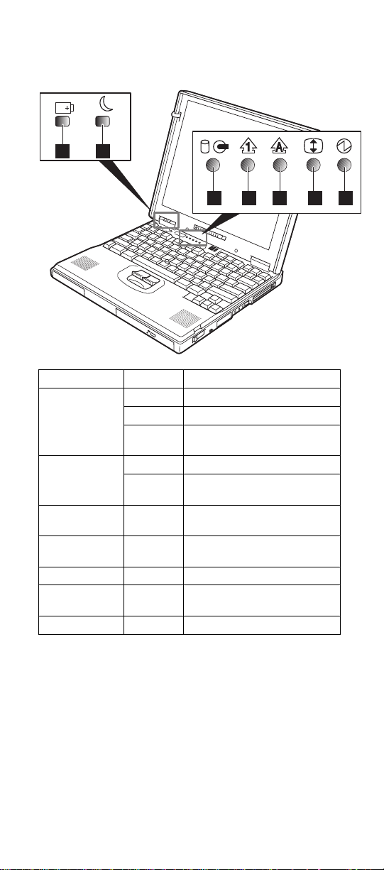
Status indicators
The system status indicators blink green or orange to show
the status of the computer.
1
2
3 4 5 6 7
Symbol Color Meaning
.1/Battery Green The battery is fully charged.
Orange The battery is charging.
Blinking
orange
.2/Suspend
mode
.3/Hard disk
in use
.4/Numeric
lock
.5/Caps lock Green Caps Lock mode is enabled.
.6/Scroll lock Green Arrow keys can be used as
.7/Power on Green Power on.
Green Suspend mode.
Blinking
green
Orange Data is read from or written
Green The numeric keypad on the
The battery needs charging.
Entering suspend mode.
to the hard disk drive.
keyboard is enabled.
screen-scroll function keys.
15
Page 20

Product overview
Fn key combinations
The following table shows the function of each combination
of Fn with a function key.
The Fn key works independently from the operating
system. The operating system obtains the status through
the system management interface to control the system.
Fn + Description
F1 Reserved.
F2 Turn the Fuel Gauge display on or
off.
F3 Turn standby mode on.
F4 Turn suspend mode on.
F5 Reserved.
F6 Reserved.
F7 Switch between the LCD and an
external monitor.
F8 Turn screen expansion on or off.
(There is no symbol on the key.)
F9 Reserved.
F10 Reserved.
F11 Switch the power management
mode:
high performance, automatic, or
customized.
Note: In Windows 98, only the
CPU speed is changed.
F12 Turn hibernation mode on.
Pg Up Increase the volume, or unmute.
Pg Dn Decrease the volume, or unmute.
Backspace Mute.
Note: To turn on the sound,
press Fn + PgUp or Fn + PgDn.
16 ThinkPad 600X Hardware Maintenance Manual
Page 21

Symptom-to-FRU error messages
Symptom-to-FRU error messages
This chapter describes the Symptom-to-FRU error
messages.
How to use error messages
Use the error codes displayed on the screen to diagnose
failures.
If two or more error codes are displayed, begin the
diagnosis with the first one. Whatever caused the first
error code can cause false error codes to be displayed.
If no error code is displayed, see if the error symptom is
listed in the “Symptom-to-FRU index.”
How to diagnose multiple FRUs
When an adapter or a device has more than one FRU, the
error code could be caused by any of them. Before
replacing multiple FRUs, try removing or exchanging each
FRU, one by one in the specified sequence, to see if the
symptoms change.
Symptom-to-FRU index
The symptom-to-FRU index lists the symptoms and errors
and their possible causes. The most likely cause is listed
first.
Note: Do the FRU replacements or other actions in the
sequence shown in the “FRU/Action in Sequence”
column. If a FRU replacement does not solve the
problem, put the original part back in the computer.
Do not replace a nondefective FRU.
This index can also help you determine, during regular
servicing, what FRUs are likely to need to be replaced
next.
A numeric error code is displayed for each error detected
in POST or system operation. In the displays, X can be
any number.
If no numeric codes is presented, use the narrative
descriptions of symptoms.
If a symptom is not listed, go to “Undetermined problems”
on page 31.
Note
For an IBM device not supported by diagnostic codes
in the ThinkPad notebook computers, see the manual
for that device.
17
Page 22

Symptom-to-FRU error messages
Numeric error codes
Symptom or error FRU or action, in
10X
101: Interrupt failure.
102: Timer failure.
103: Timer interrupt
failure.
104: Protected mode
failure.
105: Last 8042
command not
accepted.
107: NMI test failure.
108: Timer bus test
failure.
109: Low meg-chip
select test.
110
System board parity.
111
I/O parity.
11XX
1101: Serial_A test failure.
12XX
1201: Serial_B test failure.
158
No hard disk password has
been set even though the
supervisor password is set.
159
The hard disk password is
not set the same as the
supervisor password.
sequence
1. System board
1. Go to “Testing the
computer” on
page 7.
2. DIMM card.
3. If the expansion unit is
attached to the
computer, detach it.
4. System board.
1. Go to “Testing the
computer” on
page 7.
2. Expansion unit or port
replicator.
3. System board.
1. Go to “Testing the
computer” on
page 7.
2. Serial device.
3. Communication cable.
4. System board.
1. Go to “Testing the
computer” on
page 7.
2. System board
(infrared).
Set the password for the
hard disk drive.
Set the correct password
for the hard disk drive.
18 ThinkPad 600X Hardware Maintenance Manual
Page 23

Symptom-to-FRU error messages
Symptom or error FRU or action, in
161
Dead battery.
163
Time and date were not set.
173
Configuration data was lost.
174 1. Check device
175, 177, 178
175: EEPROM CRC
#1 error.
177: Supervisor
password check sum
error.
178: EEPROM is not
functional.
17XX
1701: Hard disk
controller failure.
1780, 1790: Hard disk
0 error.
1781, 1791: Hard disk
1 error.
183
Incorrect password entered
at the supervisor password
prompt.
184
Power-on password check
sum error.
185
The startup sequence is not
valid. Suspect that power
was off when the startup
sequence was being
updated.
188, 189
BAD EEPROM CRC #1. An
incorrect checksum of the
EEPROM is received.
190
A depleted battery pack was
installed while the power
was on.
sequence
1. Go to “Checking the
backup battery” on
page 12.
2. Backup battery.
3. System board.
1. Set time and date.
2. System board.
1. Select OK in the error
screen; then set the
time and date.
2. Backup battery.
3. System board.
configuration.
2. Hard disk drive
assembly.
3. System board.
1. System board.
1. Go to “Testing the
computer” on
page 7.
2. Hard disk drive.
3. System board.
Have the user examine
the password.
Reset the power-on
password in Easy-Setup.
Reset the startup
sequence in Easy-Setup.
1. System board.
Go to “Checking the
battery pack” on page 11.
19
Page 24

Symptom-to-FRU error messages
Symptom or error FRU or action, in
191XX
PM initialization error.
192
Fan error.
193
RF Antenna has been
removed.
194
The computer is carried
through the portal gate.
195
The configuration read from
the hibernation area does
not match the actual
configuration.
196
A read error occurred in the
hibernation area of the hard
disk drive.
199XX
Resume error.
1XX 1. System board.
2XX
201: Memory data
error.
202: Memory line error
00–15.
203: Memory line error
16–23.
205: Memory test
failure on on-board
memory.
221: ROM to RAM
remap error.
225
Unsupported memory
module.
sequence
1. System board.
1. Go to “Testing the
computer” on
page 7.
2. Measure the voltage of
the backup battery. If
the voltage is not
correct, replace the
backup battery.
3. Fan.
4. System board.
1. Type the correct
supervisor password
at the password
prompt.
2. Reseat the RF
Antenna to the HDD
cover.
1. Type the correct
supervisor password
at the password
prompt.
Check whether the
configuration has been
changed.
For example, check whether
the DIMM card has been
added.
1. Run the hard disk
drive test.
2. Hard disk drive.
1. System board.
1. Go to “Testing the
computer” on
page 7.
2. DIMM card.
3. System board.
1. Check if the
supported DIMM is
installed.
2. DIMM card.
3. System board.
20 ThinkPad 600X Hardware Maintenance Manual
Page 25

Symptom-to-FRU error messages
Symptom or error FRU or action, in
301, 303, 304, 305, 3XX
301: Keyboard error.
601, 6XX
601: Diskette drive or
controller error.
602
Diskette read error.
604
Unacceptable ID was read
from the diskette drive.
2402 1. TV out card.
24XX
2401: System board video
error.
808X
8081: PC Card
presence test failure.
PC Card revision
number also checked.
8082: PC Card register
test failure.
860X
Pointing device error when
TrackPoint is disabled.
8601: System bus
error–8042 mouse
interface.
8602: External mouse
error.
8603: System bus
error or mouse error.
sequence
1. Go to “Testing the
computer” on
page 7.
2. Keyboard.
3. External numeric
keypad.
4. External keyboard.
5. Keyboard and mouse
cable.
6. System board.
1. Go to “Testing the
computer” on
page 7.
2. Diskette drive
assembly.
3. Diskette.
4. System board.
1. Go to “Testing the
computer” on
page 7.
2. Diskette.
3. Diskette drive
assembly.
1. Go to “Testing the
computer” on
page 7.
2. Diskette drive
assembly.
3. System board.
1. Go to “Testing the
computer” on
page 7.
2. System board.
1. Go to “Testing the
computer” on
page 7.
2. PC Card slot
assembly.
3. PCMCIA device.
4. System board.
1. Go to “Testing the
computer” on
page 7.
2. External mouse.
3. External keyboard.
4. System board.
21
Page 26

Symptom-to-FRU error messages
Symptom or error FRU or action, in
861X
Pointing device error when
TrackPoint is enabled.
8611: System bus
error–I/F between 8042
and IPDC.
8612: TrackPoint error.
8613: System board or
TrackPoint error.
I9990301
I9990302
I9990305
I9990301: Hard disk
error.
I9990302: Invalid hard
disk boot record.
I9990305: No bootable
device.
I9990303
(Bank–2 flash ROM check
sum error.)
Other codes not listed
above.
sequence
1. Go to “Testing the
computer” on
page 7.
2. Reseat the keyboard
cable on the sub card.
3. Keyboard.
4. External mouse.
5. Sub card.
6. System board.
1. Check that the
operating system is
installed in the hard
disk drive. If not,
install the operating
system.
2. Reseat the boot
device.
3. Check the startup
sequence for the
correct boot device.
4. Check that the
operating system has
no failure and is
installed correctly.
1. System board.
Go to “Undetermined
problems” on page 31.
22 ThinkPad 600X Hardware Maintenance Manual
Page 27

Symptom-to-FRU error messages
Beep symptoms
Symptom or error FRU or action, in
Continuous beeps. 1. System board.
One beep and a blank,
unreadable, or flashing
LCD.
One beep, and the message
“Unable to access boot
source.”
One long and two short
beeps, and a blank or
unreadable LCD.
One long beep followed by
four short beeps each time
the power switch is
operated.
(System cannot power on
because of low battery
voltage.)
One beep every second.
(System is shutting down
because of low battery
voltage.)
Two short beeps with error
codes.
Two short beeps with blank
screen.
sequence
1. Reseat the LCD
connector.
2. LCD assembly.
3. System board.
1. Boot device.
2. System board.
1. System board.
2. LCD assembly.
Connect the ac adapter or
install a fully charged
battery.
Connect the ac adapter or
install a fully charged
battery. (Allow the
system to shut down
completely before
changing the battery.)
POST error. See
“Numeric error codes” on
page 18.
1. System board.
No Beep Symptoms
Symptom or error FRU or action, in
No beep, power-on indicator
not on, and a blank LCD
during POST.
No beep, power-on indicator
on, and a blank LCD during
POST.
No beep, power-on indicator
on, and a blinking cursor
only during POST.
23
sequence
1. Go to “Power system
checkout” on page 9.
2. System board.
3. Check the power
outlet.
1. System board.
1. System board.
Page 28

Symptom-to-FRU error messages
Symptom or error FRU or action, in
No beep during POST, but
system runs correctly.
sequence
1. Turn the volume up
and check the
speaker.
2. Speaker.
3. Sub card.
4. System board.
Audio-related symptoms
Symptom or error FRU or action, in
In OS/2, DOS, or Windows
multimedia programs, no
sound comes from the
computer. (Only system
beeps are heard at
power-on.)
sequence
Check that the device
driver is installed
correctly.
CD-ROM-related symptoms
Symptom or error FRU or action, in
You hear a noise from the
CD-ROM drive when the
CD-ROM is spinning.
The CD-ROM tray does not
open even if you press the
CD-ROM eject button.
sequence
1. CD-ROM drive.
2. System board.
Insert a pin into the
CD-ROM emergency eject
hole, and eject the CD-ROM
tray.
24 ThinkPad 600X Hardware Maintenance Manual
Page 29

Symptom-to-FRU error messages
Symptom or error FRU or action, in
The compact disc cannot be
read.
sequence
Make sure that:
The compact disc is
not dirty. If it is, clean
it with a CD-ROM
cleaner kit.
The compact disc is
not defective. If it is,
try another compact
disc.
The compact disc is
placed in the tray with
the label side up.
The compact disc
format has one of the
following formats:
– Music CD
– CD-ROM or
CD-ROM XA
– Multisession
photo CD
– Video CD and
CD-i movie
(Windows 95
does not support
CD-i movies)
1. CD-ROM drive.
2. System board.
25
Page 30

Symptom-to-FRU error messages
Symptom or error FRU or action, in
The CD-ROM does not
work.
sequence
Make sure that:
The computer power is
turned on and a
compact disc is in the
CD-ROM drive.
The CD-ROM drive
connector is firmly
connected to the
computer.
The CD-ROM drive
tray is firmly closed.
The device drivers are
correctly installed.
If the CD-ROM drive in the
docking station still does not
work, do the following:
1. Click on Start.
2. Move the cursor to
Programs and
ThinkPad; then click
on ThinkPad
Configuration.
3. Click on Docking
Station.
4. Make sure that you
checked Enable IDE
device in the docking
station.
Note: Do not use IRQ
11 and 15 for the PCI
device setting.
5. Click on OK.
If the problem remains,
replace the following FRUs
in order:
1. CD-ROM drive.
2. System board.
26 ThinkPad 600X Hardware Maintenance Manual
Page 31

Symptom-to-FRU error messages
Function-related symptoms
Symptom or error FRU or action, in
The system does not
suspend or resume when
the LCD is closed or
opened.
The battery Fuel Gauge
does not go higher than
90%.
The memory count (size)
appears different from the
actual size.
The system hangs
intermittently.
sequence
1. Go to “Suspend
mode” on page 5,
and check that the
computer can enter
suspend mode.
2. Boot an operating
system and press
Fn+F4. If the
computer enters
suspend mode,
suspect that the
application program is
not working properly.
3. LCD assembly.
4. System board.
Go to “Checking the
battery pack” on page 11,
and see the note.
Go to “Testing the
computer” on page 7.
Go to “Intermittent
problems” on page 31.
Indicator-related symptoms
Symptom or error FRU or action, in
The indicator incorrectly
remains off or on, but the
system runs correctly.
The battery power status
indicator blinks from green
to yellow to orange.
The battery indicator does
not turn on when the battery
is installed.
27
sequence
1. Sub card.
2. System board.
1. Check that a correct
battery is installed.
2. Battery pack.
3. System board.
1. Battery pack.
2. System board.
Page 32

Symptom-to-FRU error messages
Infrared-related symptoms
Symptom or error FRU or action, in
Unable to communicate
using the Infrared (IR) Port.
sequence
1. Make sure the setup
for the IR is correct.
Use the ThinkPad
Configurations utility.
2. Make sure there are
no fluorescent lights
near the computer.
The computer may
receive optical noise
from the fluorescent
light.
3. Run the advanced
diagnostic test. If an
error occurs and a
FRU code is displayed,
replace the parts
shown by the FRU
code.
Keyboard- or TrackPoint-related
symptoms
Symptom or error FRU or action, in
The keyboard (one or more
keys) does not work.
The TrackPoint does not
work.
The pointer moves
automatically or does not
work correctly.
sequence
1. Reseat the keyboard
cable on the sub
card.
2. Keyboard.
3. System board.
1. Reseat the keyboard
cable on the system
board.
2. Go to “Testing the
computer” on page 7.
3. Keyboard.
4. System board.
See “Testing the
computer” on page 7.
28 ThinkPad 600X Hardware Maintenance Manual
Page 33

Symptom-to-FRU error messages
LCD-related symptoms
Important
The TFT LCD for the notebook computer contains
many thin-film transistors (TFTs). A small number of
dots that are missing, discolored, or always lighted is
characteristic of TFT LCD technology, but excessive
pixel problems can cause viewing concerns. The LCD
should be replaced if the number of missing,
discolored, or lighted dots in any background is:
XGA (13.3"): 8 or more bright dots, 8 or more
dark dots, or a total of 9 or more bright and dark
dots.
Symptom or error FRU or action, in
No beep, power-on indicator
on, and a blank LCD during
POST.
LCD backlight not
working.
LCD too dark.
LCD brightness cannot
be adjusted.
LCD contrast cannot
be adjusted.
LCD screen
unreadable.
Characters missing
pixels.
Screen abnormal.
Wrong color displayed.
Extra horizontal or vertical
lines are displayed on the
LCD.
sequence
1. System board.
1. Reseat the LCD
connectors.
2. LCD assembly.
3. System board.
1. See important note
for “LCD-related
symptoms.”
2. Reseat all LCD
connectors.
3. LCD assembly.
4. System board.
1. LCD assembly.
Modem-related symptoms
Symptom or error FRU or action, in
In OS/2, DOS, or Windows
multimedia programs, no
sound comes from the
computer. (Only system
beeps are heard at
power-on.)
sequence
Check that the device
driver is installed
correctly.
29
Page 34

Symptom-to-FRU error messages
Symptom or error FRU or action, in
In OS/2, DOS, or Windows,
the modem does not work.
sequence
Check that the modem is
active.
OS/2 and Windows:
Click on the Modem icon in
the ThinkPad Configuration
program.
DOS:
Run the MWMODEM ON
command.
PC Card-related symptoms
Symptom or error FRU or action, in
PC Card does not work in
either the upper slot or the
lower slot.
PCMCIA slot pin is
damaged.
PC Card does not work. 1. Reseat the PC Card.
sequence
1. Reseat the PCMCIA
slot assembly.
2. PCMCIA slot
assembly.
3. System board.
PCMCIA slot assembly
2. Check that the PC
Card is enabled in the
ThinkPad Configuration
program.
3. Reseat the PCMCIA
slot assembly.
4. PCMCIA slot
assembly.
5. System board.
Peripheral-device-related symptoms
Symptom or error FRU or action, in
The external monitor does
not work correctly.
Printer problems. 1. Run printer self-test.
Serial or parallel port device
problems.
30 ThinkPad 600X Hardware Maintenance Manual
sequence
Connect the external
monitor to another PC. If
the monitor works
properly, replace the
system board. If not,
replace the external
monitor.
2. Run parallel port wrap
test.
3. System board.
4. Printer cable.
1. Run serial/parallel
port wrap test.
2. Device.
3. System board.
4. Device cable.
Page 35

Symptom-to-FRU error messages
Power-related symptoms
Symptom or error FRU or action, in
Power shuts down during
operation.
The system does not power
off.
(See “Reset switch” on
page 3.)
sequence
1. Go to “Power system
checkout” on page 9.
2. Battery pack.
3. Remove the battery
pack and let it cool for
2 hours.
4. System board.
5. Check the power
outlet.
1. Press the power
shutdown switch.
2. System board.
Other symptoms
Symptom or error FRU or action, in
Errors occur only when the
port replicator is used.
PC Card slot pin is
damaged.
sequence
See “Port replicator
checkout” on page 12.
1. PC Card slots
assembly
Note: If you cannot find a symptom or an error in this list
and the problem remains, see “Undetermined
problems.”
Intermittent problems
Intermittent system hang problems can be caused by a
variety of reasons that have nothing to do with a hardware
defect, such as cosmic radiation, electrostatic discharge, or
software errors. FRU replacement should be considered
only when a problem recurs.
When analyzing an intermittent problem, do the following:
1. Run the advanced diagnostic test for the system
board in loop mode at least 10 times.
2. If no error is detected, do not replace any FRUs.
3. If any error is detected, replace the FRU shown by
the FRU code. Rerun the test to verify that no more
errors exist.
Undetermined problems
You are here because the diagnostic tests did not identify
which adapter or device failed, installed devices are
incorrect, a short circuit is suspected, or the system is
inoperative. Follow these procedures to isolate the failing
FRU (do not isolate nondefective FRUs).
31
Page 36

Symptom-to-FRU error messages
Verify that all attached devices are supported by the
computer.
Verify that the power supply being used at the time of the
failure is operating correctly. (See “Power system
checkout” on page 9):
1. Power off the computer.
2. Visually check the attached devices damage. If any
problems are found, replace the FRU.
3. Remove or disconnect all of the following devices:
a. Non-IBM devices
b. Devices attached to the port replicator
c. Printer, mouse, and other external devices
d. Battery pack
e. Hard disk drive
f. External diskette drive
g. DIMM
h. CD-ROM and diskette drive in the UltraslimBay
i. PC Cards
4. Power on the computer.
5. Determine whether the problem has changed.
6. If the problem does not recur, reconnect the removed
devices one at a time until you find the failing FRU.
7. If the problem remains, replace the following FRUs,
one at a time. Do not replace a nondefective FRU:
a. System board
b. LCD assembly
c. CPU card
32 ThinkPad 600X Hardware Maintenance Manual
Page 37

FRU replacement notices
FRU replacement notices
This section contains notices for removal and replacement.
Read this section carefully before replacing any FRU.
Screw notices
Loose screws can cause a reliability problem. The IBM
ThinkPad computer address this problem with special
nylon-coated screws that have the following characteristics:
They maintain tight connections.
They do not easily come loose, even with shock or
vibration.
They need additional force to tighten.
They should be used only once.
Do the following when you service this machine:
Keep the screw kit (P/N 05K4841) in your tool bag.
Always use new screws if you are instructed.
Use a torque screwdriver if you have one.
Tighten screws as follows:
Plastic to plastic
Turn an additional 90 degrees after the screw head
touches the surface of the plastic part:
Logic card to plastic
Turn an additional 180 degrees after the screw head
touches the surface of the logic card:
Torque driver
If you have a torque driver, refer to the “Torque”
column with each step.
Make sure you use the correct screw, and tighten all
screws firmly to the torque shown in the table if you
33
Page 38

FRU replacement notices
have a torque screwdriver. Never use a screw that
you removed. Use a new one. Make sure the
screws are tightened firmly
Retaining serial numbers
This section includes the following descriptions:
“Restoring serial number of the system unit”
“Retaining the UUID”
Restoring serial number of the system
unit: When the computer was manufactured, the
EEPROM on the system board was loaded with the serial
numbers of the system and all major components. The
system serial number must remain the same throughout
the life of the computer.
When you replace the system board, you must restore the
system unit serial number to its original value.
Before replacing the system board, save the original serial
number by doing the following:
1. Install the ThinkPad Hardware Maintenance Diskette
Version 1.60 and restart the computer.
2. From the main menu, select 1. Set System
Identification.
3. Select 2. Read S/N data from EEPROM.
The serial number for each device is displayed. Write
down the serial number of the system unit, designated as
follows:
20: System unit serial number
After you have replaced the system board, restore the
serial number by doing the following:
1. Install the ThinkPad Hardware Maintenance Diskette
Version 1.60 and restart the computer.
2. From the main menu, select 1. Set System
Identification.
3. Select 1. Add S/N data from EEPROM.
Follow the instructions on the screen.
Note: The serial number of the system unit is written on
the label attached on the bottom of the computer.
Retaining the UUID: The Universally Unique
IDentifier (UUID) is a 128-bit number uniquely assigned to
your computer at production and stored in the EEPROM of
your system board. The algorithm that generates the
unique number is designed to provide unique IDs until the
year A.D. 3400. No two computers in the world have the
same number.
When you replace the system board, you must set the
UUID on the new system board as follows:
34 ThinkPad 600X Hardware Maintenance Manual
Page 39

FRU replacement notices
1. Install the ThinkPad Hardware Maintenance Diskette
Version 1.60, and restart the computer.
2. Select 4. Assign UUID from the main menu.
A new UUID is created and written. If a valid UUID
already exists, it is not overwritten.
35
Page 40

FRU removals and replacements
FRU removals and replacements
This section presents information and drawings for use in
removing and replacing a FRU. Be sure to observe the
following general rules:
1. Do not try to service the computer unless you have
been trained and certified. An untrained person runs
the risk of damaging parts.
2. Before replacing any FRU, review “FRU replacement
notices” on page 33.
3. Begin by removing any FRUs that have to be
removed before the failing FRU. Any such FRUs are
listed at the top of the page. Remove them in the
orders in which they are listed.
4. Follow the correct sequence in the steps for removing
the FRU, as indicated in the drawings by the numbers
in square callouts.
5. When turning a screw to replace a FRU, turn it in the
direction indicated by the arrow in the drawing.
6. When removing the FRU, move it in the direction
indicated by the arrow in the drawing.
7. To put the new FRU in place, reverse the removal
procedure and follow any notes that pertain to
replacement. For information about connecting and
arranging internal cables, see “Locations” on
page 65.
8. When replacing a FRU, use the correct screw as
shown in the procedures.
Caution
Before removing any FRU, power off the computer,
unplug all power cords from electrical outlets, remove
the battery pack, and then disconnect any
interconnecting cables.
Caution
The battery pack contains small amounts of nickel.
Do not disassemble it, throw it into fire or water, or
short-circuit it. Dispose of the battery pack as
required by local ordinances or regulations.
Attention
Before the computer is powered on after FRU
replacement, make sure all screws, springs, and other
small parts are in place and are not loose inside the
computer. Verify this by shaking the computer gently
and listening for rattling sounds. Metallic parts or
metal flakes can cause electrical short circuits.
36 ThinkPad 600X Hardware Maintenance Manual
Page 41

FRU removals and replacements
Attention
The system board is sensitive to, and can be
damaged by, electrostatic discharge. Establish
personal grounding by touching a ground point with
one hand before touching these units.
You must use an electrostatic discharge (ESD) strap
(P/N 6405959) must be used to establish personal
grounding.
37
Page 42

FRU removals and replacements
1010 Backup battery
Caution
The backup battery is a lithium battery and can cause
a fire, an explosion, or severe burns. Do not recharge
it, remove its polarized connector, disassemble it, heat
it above 100°C (212°F), incinerate it, or expose its cell
contents to water. Dispose of the battery as required
by local ordinances or regulations. The use of an
incorrect battery can result in ignition or explosion of
the battery.
Note: Loosen the screw .1/, but do not remove it.
1
2
3
1
2
38 ThinkPad 600X Hardware Maintenance Manual
Page 43

1020 DIMM
FRU removals and replacements
39
Page 44

FRU removals and replacements
1025 Modem card
40 ThinkPad 600X Hardware Maintenance Manual
Page 45

1030 Battery pack
FRU removals and replacements
Unlock
Lock
2
1
41
Page 46

FRU removals and replacements
1040 Hard disk drive
Attention
Do not drop or apply any shock to the hard disk
drive. The hard disk drive is sensitive to physical
shock. Incorrect handling can cause damage and
permanent loss of data.
Before removing the drive, have the user make a
backup copy of all the information on the drive if
possible.
Never remove the drive while the system is operating
or is in suspend mode.
1
3
2
Step Screw (Quantity) Color Torque
.1/ Coin screw
—Or—
Security screw
Note: Use a 2.5-mm allen wrench to remove the security
screw.
If you install an hard disk drive with a depth of 12mm, you
need to remove a spacer. To remove a spacer, do as
follows:
When replacing:
Make sure that the hard disk drive connector is
firmly connected.
Black —
42 ThinkPad 600X Hardware Maintenance Manual
Page 47

FRU removals and replacements
1050 UltraslimBay device
1
2
When the security screw is installed
In step .1/, use a 2.5-mm allen wrench to remove the
security screw.
1
2
3
4
43
Page 48

FRU removals and replacements
1060 Keyboard assembly
Battery pack (1030)
Hard disk drive (1040)
UltraslimBay device (1050)
1
2
3
Step Screw (Quantity) Color Torque
.1/ M2.5 × 19.5 mm,
nylon-coated (3)
.2/ M2.5 × 16 mm,
nylon-coated (2)
.3/ M2.5 × 4.8 mm,
nylon-coated (1)
.4/ M2.5 × 3 mm,
nylon-coated (4)
Black 4 kgcm
Black 4 kgcm
Black 4 kgcm
Yellow 4 kgcm
4
Now turn the computer right side up.
(Continued)
44 ThinkPad 600X Hardware Maintenance Manual
Page 49

FRU removals and replacements
5
Step Screw (Quantity) Color Torque
.5/ M2.5 × 4.8 mm,
nylon-coated (1)
Black 4 kgcm
6
Latch
7
(Continued)
45
Page 50

FRU removals and replacements
8
46 ThinkPad 600X Hardware Maintenance Manual
Page 51

FRU removals and replacements
1070 Keyboard
Battery pack (1030)
Hard disk drive (1040)
UltraslimBay device (1050)
Keyboard assembly (1060)
Note: In step .1/, remove the insulator gently for it is
reused.
2
3
4
1
2
Bottom view
4
Step Screw (Quantity) Color Torque
.2/ M2.5 × 3 mm,
nylon-coated (6)
47
Yellow 4 kgcm
Page 52

FRU removals and replacements
1080 Speakers
Battery pack (1030)
Hard disk drive (1040)
UltraslimBay device (1050)
Keyboard assembly (1060)
Note: In step .1/, remove the insulator on the left
speaker.
2
3
2
4
1
4
Bottom view
Step Screw (Quantity) Color Torque
.2/ M2.5 × 3 mm,
nylon-coated (6)
(Continued)
Yellow 4 kgcm
48 ThinkPad 600X Hardware Maintenance Manual
Page 53

FRU removals and replacements
Cable route:
When replacing the right speaker, see the following figure
for its cable route.
Right speaker
49
Page 54

FRU removals and replacements
1085 Speaker cable
Battery pack (1030)
Hard disk drive (1040)
UltraslimBay device (1050)
Keyboard assembly (1060)
Note: In step .1/, remove the insulator on the left
speaker.
2
4
1
3
Bottom view
Step Screw (Quantity) Color Torque
.2/ M2.5 × 3 mm,
nylon-coated (2)
Yellow 4 kgcm
50 ThinkPad 600X Hardware Maintenance Manual
Page 55

FRU removals and replacements
1090 LCD assembly
Battery pack (1030)
Hard disk drive (1040)
UltraslimBay device (1050)
Keyboard assembly (1060)
1
3
4
2
3
5
6
Step Screw (Quantity) Color Torque
.1/ M2.5 × 4.8 mm,
nylon-coated (4)
.3/ M2.5 × 4.8 mm,
nylon-coated (4)
.4/ M2.5 × 4.8 mm,
nylon-coated (1)
Black 4 kgcm
Black 4 kgcm
Black 4 kgcm
7
51
Page 56

FRU removals and replacements
1100 PC Card slot assembly
Battery pack (1030)
Hard disk drive (1040)
UltraslimBay device (1050)
Keyboard assembly (1060)
2
Connector
Step Screw (Quantity) Color Torque
.1/ M2.0 × 9.5 mm,
nylon-coated (4)
Black 2.5 kgcm
1
3
52 ThinkPad 600X Hardware Maintenance Manual
Page 57

FRU removals and replacements
1110 Asset ID RF adapter kit
Battery pack (1030)
Hard disk drive (1040)
UltraslimBay device (1050)
Keyboard assembly (1060)
53
Page 58

FRU removals and replacements
1120 Sub card
Battery pack (1030)
Hard disk drive (1040)
UltraslimBay device (1050)
Keyboard assembly (1060)
LCD assembly (1090)
2
Cennector
3
1
Step Screw (Quantity) Color Torque
.2/ M2.5 × 4.8 mm,
nylon-coated (2)
Black 4 kgcm
54 ThinkPad 600X Hardware Maintenance Manual
Page 59

FRU removals and replacements
1130 Guide rail, microphone cable, or TV Out card
Battery pack (1030)
Hard disk drive (1040)
UltraslimBay device (1050)
Keyboard assembly (1060)
Sub card (1120)
Step Screw (Quantity) Color Torque
.4/ M2.0 × 9.5 mm,
nylon-coated (1)
.5/ M2.5 × 4.8 mm,
nylon-coated (2)
.7/ M2.5 × 7 mm,
nylon-coated (1)
Black 2.5 kgcm
Black 4 kgcm
Yellow 4 kgcm
When replacing:
Make sure the connector on the TV Out card is
firmly connected.
55
Page 60

FRU removals and replacements
1140 CPU card and fan
Battery pack (1030)
Hard disk drive (1040)
UltraslimBay device (1050)
Keyboard assembly (1060)
2
3
4
3
1
Cennector
Step Screw (Quantity) Color Torque
.1/ M2.0 × 9.5 mm,
nylon-coated (1)
.3/ M2.0 × 9.5 mm,
nylon-coated (4)
(Continued)
Black 2.5 kgcm
Black 2.5 kgcm
56 ThinkPad 600X Hardware Maintenance Manual
Page 61

FRU removals and replacements
5
Fan
6
CPU card
Step Screw (Quantity) Color Torque
.5/ M2.0 × 4.0 mm,
nylon-coated (2)
When replacing:
When you replace the CPU card, press it only at the
places indicated in the figure. Press both sides at the
same time. Do not press only one side or any other
part of the card; to do so might damage it.
Black 2.5 kgcm
Press here
A
57
Page 62

FRU removals and replacements
1150 Modem cable assembly
Battery pack (1030)
Hard disk drive (1040)
UltraslimBay device (1050)
Keyboard assembly (1060)
1
2
3
Step Screw (Quantity) Color Torque
.1/ M2.5 × 4.8 mm,
nylon-coated (1)
Black 4 kgcm
(Continued)
58 ThinkPad 600X Hardware Maintenance Manual
Page 63

FRU removals and replacements
Cable route:
When replacing the modem cable, see the preceding figure
for its cable route.
Step Screw (Quantity) Color Torque
.4/ M2.5 × 4.8 mm,
nylon-coated (2)
Black 4 kgcm
59
Page 64

FRU removals and replacements
1160 System board
Backup battery (1010)
DIMM (1020)
Modem card (1025)
Battery pack (1030)
Hard disk drive (1040)
UltraslimBay device (1050)
Keyboard assembly (1060)
LCD assembly (1090)
PC Card slot assembly (1100)
Sub card (1120)
TV Out card (1130)
CPU card and fan (1140)
Modem cable assembly (1150)
2
3
4
1
Step Screw (Quantity) Color Torque
.1/ M2.5 × 4.8 mm,
nylon-coated (3)
.2/ M2.5 × 4.8 mm,
nylon-coated (1)
Black 4 kgcm
Black 4 kgcm
60 ThinkPad 600X Hardware Maintenance Manual
Page 65

FRU removals and replacements
2010 LCD front cover
Battery pack (1030)
Hard disk drive (1040)
UltraslimBay device (1050)
Keyboard assembly (1060)
LCD assembly (1090)
Important
The TFT LCD for the notebook computer contains
many thin-film transistors (TFTs). A small number of
dots that are missing, discolored, or always lighted is
characteristic of TFT LCD technology, but excessive
pixel problems can cause viewing concerns. The LCD
should be replaced if the number of missing,
discolored, or lighted dots in any background is:
XGA (13.3"): 8 or more bright dots, 8 or more
dark dots, or a total of 9 or more bright and dark
dots.
Step Screw (Quantity) Color Torque
.1/ M2.5 × 4.8 mm,
nylon-coated (6)
Black 4 kgcm
61
Page 66

FRU removals and replacements
2020 LCD Hinges and cables
Battery pack (1030)
Hard disk drive (1040)
UltraslimBay device (1050)
Keyboard assembly (1060)
LCD Assembly (1090)
LCD front cover (2010)
(Continued)
62 ThinkPad 600X Hardware Maintenance Manual
Page 67

FRU removals and replacements
When you replace the cables, make sure they are not
caught by the LCD panel.
5
5
63
Page 68

FRU removals and replacements
2030 Inverter card
Battery pack (1030)
Hard disk drive (1040)
UltraslimBay device (1050)
Keyboard assembly (1060)
LCD assembly (1090)
LCD front cover (2010)
3
1
2
Step Screw (Quantity) Color Torque
.1/ M2.5 × 4.8 mm,
nylon-coating (1)
Black 4 kgcm
64 ThinkPad 600X Hardware Maintenance Manual
Page 69

Locations
Front view
.1/ LCD panel
.2/ Brightness control
.3/ Built-in microphone
.4/ PC Card slots
.5/ PC Card eject button
.6/ Infrared port
.7/ Headphone jack
.8/ Line-in jack
.9/ Microphone jack
.1ð/ External diskette drive
.11/ Diskette-eject button
.12/ Video-out connector
.13/ LCD latch
.14/ UltraslimBay
Note: The UltraslimBay accepts storage devices,
such as a DVD drive or a CD-ROM.
.15/ Click buttons
.16/ Hard disk drive
.17/ Fn key
.18/ Internal speaker
.19/ TrackPoint stick
.2ð/ System-status indicators
Locations
1
20
19
18
17
16
2
3
4
5
6
15
14
12
8
9
10
13
65
11
Page 70

Locations
Rear view
.1/ Security keyhole
.2/ Modem connector
.3/ Power switch
.4/ Reset switch
.5/ Universal serial bus (USB) connector
.6/ Power jack
.7/ Serial connector
.8/ System-expansion connector
.9/ Parallel connector
.1ð/ External-monitor connector
.11/ External-input-device connector
11
10
9
8
6
1
2
3
4
5
ThinkPad 600X Hardware Maintenance Manual
66
Page 71

Bottom view
.1/ UltraslimBay device lock
.2/ Bay LED
.3/ Memory-slot cover
.4/ Memory slots
.5/ Mini-PCI modem slots
.6/ Battery-pack latch
.7/ Serial number label
.8/ Space for the name plate
.9/ Hard-disk-drive screw
.1ð/ Battery pack
Locations
67
Page 72

Locations
Password pads
68 ThinkPad 600X Hardware Maintenance Manual
Page 73

Parts list
Parts list
69
Page 74

Parts list
No. FRU P/N
1 LCD unit (see “LCD FRU” on page 73.)
2 Center cover (see System miscellaneous parts)
3 Keyboard bezel 05K7046
Keyboard bezel for Korea 05K7048
4 Keyboard (see “Keyboard” on page 72)
5 CPU card (450 MHz) 10L1354
CPU card (500 MHz) 10L1355
CPU card, for 2465-5Fx and -9Fx 10L1356
6 Sub card 10L1335
7 System board 10L1353
System board, for 2465-5Fx and -9Fx 08K3110
8 Guide rail (see System miscellaneous parts)
9 Base cover (2645) 27L6587
for China 27L6588
for Korea 27L6589
Base cover (2646) 08K5769
for China 08K5770
for Korea 08K5771
Base cover, for AAP 08K5768
10 PC Card slots 05K4790
11 DVD drive (6X) 05K9196
CD-ROM drive (LG) 05K9267
CD-ROM drive (TOSHIBA) 27L3711
Diskette drive (TEAC) 05K8874
12 DIMM cover 05K7064
13 Battery pack 10L2158
14 Cover, hard disk drive 05K5995
15 Hard disk drive (6.0 GB) 22L0055
Hard disk drive (12.0 GB) 22L0053
Hard disk drive (18.0 GB) 22L0051
Bracket, Hard disk drive 05K4752
16 Backup battery 02K6502
17 Backup battery holder 05K4827
18 Power switch knob (see System miscellaneous parts)
19 Cable, modem 27L0501
09N0791
09N0795
(Continued)
70 ThinkPad 600X Hardware Maintenance Manual
Page 75

Parts list
No. FRU P/N
20 Cover, modem 08K6031
21 Modem card 08K3429
22 Fan assembly 08K5909
Fan assembly, for 2465-5Fx and -9Fx 08K6290
23 Keyboard bracket (see System miscellaneous parts)
24 TrackPoint III cap 84G6536
25 Speaker 02K4897
Cable, diskette drive 05K2844
Doors
Diskette drive
I/O right
I/O left
USB
TV out card 10L1352
Screw kit
All nylon-coated screws:
M2 x 4 mm, pan head (5)
M2 x 9 mm, flat head (10)
M2.5 x 3 mm, flat head (20)
M2.5 x 4.8 mm, flat head (30)
M2.5 x 9 mm, flat head (10)
M2.5 x 3 mm, flat head small (5)
M3 x 3 mm, flat head (5)
Hex stud D-sub (10)
Screw caps (10)
Screw caps, front (5)
Screw caps, side (5)
Screw caps, rear (5)
System miscellaneous parts
Blank cover, modem
Spacer, HDD cover
Label, S/N blank
Screw cap
System board miscellaneous kit
I/O plate
Hex stud bus
Hex stud D-Sub
Cover, diskette drive or audio
USB plate
Holder, sub card
Pan head screw M 2x 4
Pan head screw M 2.4 x 4.8
Screw cap
Base miscellaneous part 05K6297
HDD Screw Kit 05K6073
05K4828
05K4841
05K6298
27L6590
71
Page 76

Parts list
Keyboard
Language P/N
Arabic 02K4837
Belgian 02K4801
Czech 02K4839
Canadian French 02K4788
Danish 02K4794
Dutch 02K4791
French 02K4790
German 02K4789
Greek 02K4843
Hungary 02K4841
Hebrew 02K4835
Italian 02K4795
Japanese 02K4786
Korean 02K4800
Latin American Spanish 02K4799
Norwegian 02K4793
Portuguese 02K4798
Russian 02K4833
Spanish 02K4796
Swedish or Finnish 02K4792
Swiss 02K4797
Taiwan 02K4803
Turkish 02K4802
U.K. English 02K4787
U.S. English 02K4785
72 ThinkPad 600X Hardware Maintenance Manual
Page 77

LCD FRU
13.3-inch XGA TFT
Parts list
No. FRU P/N
LCD unit (Samsung) 05K9546
LCD unit (LG) 05K9547
(Continued)
73
Page 78

Parts list
.
No. FRU P/N
1 LCD cover kit
Rear cover
Front bezel
Brightness knob
Latches (right and left)
Cover, cable
Screw cap
for Korea 08K5979
2 LCD panel (see LCD unit)
3 Hinges 05K4835
4 LCD cables 22L1891
5 Inverter card 10L1350
08K5978
74 ThinkPad 600X Hardware Maintenance Manual
Page 79

Parts list
Option list
AC adapter (56W, Sanken) 02K6555
AC adapter for Japan 02K6554
AC adapter (56W, ASTEC) 02K6557
AC adapter for Japan (56W, ASTEC) 02K6556
Battery attachment 02K6501
Battery charger 11J9003
Blank bezel for bay 05K4842
Carrying case, for CD-ROM 05K4843
Enhanced video cable 05K2821
External diskette drive case 05K6187
Modem kit
for Austria 22L1863
for Australia 22L1939
for Belgium 22L1861
for Brazil 22L1871
for Cyprus 22L1887
for Denmark 22L1879
for France 22L1862
for Germany 22L1877
for Indonesia 22L1872
for Israel 22L1935
for Italy 22L1865
for Malaysia 22L0425
for Mexico 22L1870
for Netherlands 22L1878
for New Zealand 22L1937
for Norway or Finland 22L1880
for Pakistan 22L1873
for Philippines 22L1874
for Portugal 22L1883
for Singapore 22L1941
for Spain 22L1866
for Sweden 22L1881
75
Page 80

Parts list
for Switzerland 22L1882
for Turkey 22L1884
for U.K. 22L1876
for Vietnam 22L1875
Secondary battery 02K6505
Slim Bay adapter 05K5858
SelectaBase 600 12J2480
SuperDisk (LS-120) UltraslimBay drive 20L1922
Telephone cable 05K2707
UltraslimBay HDD adapter 05K5338
24X-10X IDE CD-ROM drive 12J2471
6.4-GB hard disk drive 02K0518
DVD UltraslimBay drive
for North America (Region 1) 05K8890
for Japan and EMEA (Region 2) 05K8891
for AP North and AP South (Region 3) 05K8832
For LA and AP South (Region 4) 05K8893
for Russia (Region 5) 05K8959
for China (Region 6) 05K8960
32-MB SDRAM SO DIMM 20L0243
64-MB SDRAM SO DIMM 20L0264
128-MB SDRAM SO DIMM 20L0265
256-MB SDRAM SO DIMM 33L3070
Miniature mouse (black) 07G0033
Common Parts List
Tools
Triconnector wrap plug 72X8546
PC test card 35G4703
Audio wrap cable 66G5180
USB parallel test cable 05K2580
Screwdriver kit 95F3598
Torque screwdriver 05K4695
5mm socket wrench 05K4694
Screwdriver 27L8126
ThinkPad hardware maintenance diskette
version 1.60
Note: Download the file from the Web site.
76 ThinkPad 600X Hardware Maintenance Manual
–
Page 81

Parts list
Power cords: IBM power cords for a specific country
are usually available only in that country:
For 2-pin power cords:
Used in these countries P/N
Japan 13H5273
Argentina 36L8870
For 3-pin power cords:
Used in these countries P/N
Argentina 36L8867
People's Republic of China (other than Hong
Kong)
Argentina, Australia, New Zealand, Papua New
Guinea, Paraguay, Uruguay
Aruba, Bahamas, Barbados, Bermuda, Bolivia,
Brazil, Canada, Cayman Islands, Colombia,
Costa Rica, Curaçao, Dominican Republic,
Ecuador, El Salvador, Guatemala, Guyana,
Haiti, Honduras, Jamaica, Korea (South),
Liberia, Mexico, Netherlands Antilles, Nicaragua,
Panama, Peru, Philippines, Saudi Arabia,
Suriname, Taiwan, Thailand, Trinidad (West
Indies), United States of America, Venezuela
Austria, Belgium, Bosnia-Herzogovina, Bulgaria,
Croatia, Czech Republic, Egypt, Finland, France,
Germany, Greece, Hungary, Iceland, Indonesia,
Macao, Macedonia, Netherlands, Norway,
Poland, Portugal, Romania, Slovakia, Slovenia,
Spain, Sweden, Turkey, Yugoslavia
Denmark 76H3520
Bangladesh, Myanmar, Pakistan, South Africa,
Sri Lanka
Abu Dhabi, Albania, Antigua, Bahrain, Brunei,
Dubai, Fiji, Hong Kong, India, Ireland, Kenya,
Kuwait, Malaysia, Nigeria, Oman, Qatar,
Singapore, United Kingdom
Liechtenstein, Switzerland 76H3528
Chile, Ethiopia, Italy, Libya 76H3530
Israel 76H3532
Korea 76H3535
76H3514
76H3516
02K0539
76H3518
76H3522
76H3524
77
Page 82

Notices
References in this publication to IBM products, programs,
or services do not imply that IBM intends to make these
available in all countries in which IBM operates. Any
reference to an IBM product, program, or service is not
intended to state or imply that only that IBM product,
program, or service may be used. Any functionally
equivalent product, program, or service that does not
infringe any of the intellectual property rights of IBM may
be used instead of the IBM product, program, or service.
The evaluation and verification of operation in conjunction
with other products, except those expressly designated by
IBM, are the responsibility of the user.
IBM may have patents or pending patent applications
covering subject matter in this document. The furnishing
of this document does not give you any license to these
patents. You can send license inquiries, in writing, to the
IBM Director of Licensing, IBM Corporation, 500 Columbus
Avenue, Thornwood, NY 10594, U.S.A.
Trademarks
The following terms are trademark of the IBM Corporation
in the United States or other countries or both:
IBM
ThinkPad
TrackPoint
Ultrabase
Asset ID
PC-Doctor DOS is a trademarks of Watergate Software,
Inc., in the United States and other countries.
Microsoft, Windows, Windows NT, and the Windows logo
are trademarks of Microsoft Corporation in the United
States and/or other countries.
ActionMedia, LANDesk, MMX, Pentium, and ProShare are
trademarks of Intel Corporation in the Unites States and/or
other countries. (For a complete list of Intel trademarks,
see http://www.intel.com/trademarx.htm)
Other company, product, or service names may be the
trademarks or service marks of others.
78 ThinkPad 600X Hardware Maintenance Manual
 Loading...