


Page 1

IBM Ethernet Switch s-series
Installation and User Guide
Service information: 4003-S08, -S16
GC27-2243-00
Page 2

Page 3

IBM Ethernet Switch s-series
Installation and User Guide
Service informatio n: 400 3-S08 , -S16
GC27-2243-00
Page 4

The following paragraph does not apply to any country (or region) where such provisions are inconsistent with local
law.
INTERNATIONAL BUSINESS MACHINES CORPORATION PROVIDES THIS PUBLICATION ″AS IS″ WITHOUT
WARRANTY OF ANY KIND, EITHER EXPRESS OR IMPLIED, INCLUDING, BUT NOT LIMITED TO, THE IMPLIED
WARRANTIES OF MERCHANTABILITY OR FITNESS FOR A PARTICULAR PURPOSE. Some states (or regions) do
not allow disclaimer of express or implied warranties in certain transactions; therefore, this statement may not apply
to you.
Order publications through your IBM representative or the IBM branch office serving your locality.
© Copyright International Business Machines Corporation 2009.
US Government Users Restricted Rights – Use, duplication or disclosure restricted by GSA ADP Schedule Contract
with IBM Corp.
Page 5

Contents
Figures ............................ix
Tables ............................xi
Preface ...........................xiii
Safety notices .........................xiii
Safety notices and labels ....................xiii
Notes ..........................xiv
Attention notices ......................xiv
Caution notices.......................xiv
Danger notices .......................xv
Safety labels .......................xviii
Rack safety .........................xx
Rack installation ......................xx
Rack relocation (19″ rack)...................xxi
Product recycling and disposal ...................xxi
Product documents .......................xxii
Software documents ......................xxii
Getting help .........................xxiii
Taiwan Contact Information ...................xxiii
How to send your comments ...................xxiv
Chapter 1. About This Guide ...................1
Audience ...........................1
Nomenclature ..........................1
Chapter 2. Product Overview ...................3
Hardware benefits ........................3
POE port density ........................4
Supported configurations......................4
Software features........................4
Power over Ethernet (POE) applications ................5
Support for IPv6 modules .....................5
IPv6 hardware support guidelines ..................5
Hardware features ........................5
B08S .............................6
B16S .............................7
Management modules.......................9
B08S and B16S management modules ...............10
10/100/1000 GbE copper port on the B08S and B16S management
modules ........................11
10-GbE ports on the B08S and B16S 2-port 10-GbE management modules 11
LEDs on the B08S and B16S management modules .........11
Console port ........................12
Reset button ........................12
Switch fabric modules ......................12
LEDs on the switch fabric module .................13
Interface modules ........................13
Hot swap support .......................13
24-port 10/100/1000 Mbps Ethernet RJ45 copper interface module.....14
LEDs for 24-port 10/100/1000 Mbps Ethernet RJ45 copper interface
module .........................14
24-port 100/1000 Mbps Ethernet hybrid fiber (SFP) interface module ....15
© Copyright IBM Corp. 2009 iii
Page 6

Support for 100Base-FX on the 100/1000 interface module ......16
2-port 10-Gigabit Ethernet interface modules .............16
LEDs for 2-port 10-Gigabit Ethernet module ............17
Network interfaces .......................17
Port regions ..........................17
Power supplies .........................18
About replacement power supplies ................21
Power supply LEDs ......................22
About redundant power supplies and power supply failure ........23
What happens when one or more system power supplies fail ......23
What happens when one or more POE power supplies fail .......23
Cooling system .........................24
Built-in mounting brackets .....................25
Layer 3 routing protocol table sizes .................25
Chapter 3. Installing the Chassis .................27
Summary of installation tasks ...................27
Unpacking a system .......................28
Installation precautions ......................28
General precautions .......................28
Power precautions and warnings ..................29
Preparing the installation site....................29
Cabling infrastructure .....................29
Installation location ......................29
Removing extra shipment screws (B08S only) ............29
Installing a chassis in a rack ....................30
Installing mounting brackets on the B16S ...............32
Removing the slot panels .....................32
Installing the management and interface modules ............33
Attaching a management station ..................37
Attaching a PC or terminal to the console port or 10/100/1000 copper port . . . 37
Attaching a switch to an Ethernet port ................38
Powering on the system .....................38
Connecting AC power to the chassis .................38
Verifying proper operation .....................40
Observing the LEDs .......................40
Displaying the module status ....................42
Chapter 4. Connecting Network Devices and Checking Connectivity ...45
Assigning permanent passwords ..................45
Configuring IP addresses .....................46
IPv4 devices ..........................46
IPv4 devices running layer 3 software ...............46
IPv4 devices running layer 2 software ...............47
IPv6 devices ..........................48
IPv6 devices running Layer 3 software ...............48
IPv6 devices running Layer 2 software ...............49
Connecting network devices ....................50
Cable specifications .......................50
Connecting to Ethernet or fast Ethernet hubs ..............50
Connecting to workstations, servers, or routers .............51
Connecting a network device to a fiber port on the device .........52
Installing a fiber optic module ..................52
Cabling a fiber optic module
Cleaning fiber optic modules ...................53
Automatic MDI/MDIX detection ...................53
iv Ethernet Switch s-series Installation and User Guide
...................52
Page 7

Using a CX4 transceiver .....................53
Testing network connectivity ....................54
Pinging an IP address .....................54
Observing LEDs .......................54
Tracing a route ........................55
Troubleshooting network connections................56
Digital optical monitoring .....................56
Chapter 5. Managing the Chassis and Modules ............57
Displaying chassis status and temperature readings ...........57
Managing the cooling system ...................61
Configuring the cooling system ..................61
Thermal planes .......................61
Fan speed modes ......................61
Changing temperature thresholds for thermal planes and fan speeds on
the on the B16S .....................62
Changing temperature thresholds for thermal planes and fan speeds on
the B08S ........................64
Shutdown warning messages .................67
Changing the temperature polling interval .............68
Manually setting the fan speed .................68
Monitoring the cooling system ...................68
Displaying the temperature ...................68
Displaying fan status and speed .................69
Displaying temperature warnings .................69
Displaying the syslog configuration and static and dynamic buffers ......70
Static and dynamic buffers ...................70
Syslog messages for PCI (hardware) errors ..............71
Managing the switch fabric modules .................71
Displaying management module CPU usage ..............72
Removing MAC address entries ..................72
Chapter 6. Using a redundant management module ..........75
How management module redundancy works .............75
Management module redundancy overview ..............75
Management module switchover ..................76
Unavailable active module....................76
Manual switchover ......................76
Removal and replacement of a management module ..........76
Removal and replacement of an active management module ......76
Removal and replacement of a standby management module......77
Switchover implications ......................77
Management sessions .....................77
Syslog and SNMP traps ....................78
MAC address changes .....................78
Management module redundancy configuration .............78
Changing the default active chassis slot................78
Managing management module redundancy ..............78
File synchronization between the active and standby management modules 79
Manually switching over to the standby management module ........80
Rebooting the active and standby management modules .........81
Hitless management support ....................81
What happens during a hitless OS upgrade and hitless switchover ......81
How a hitless OS upgrade and hitless switchover impacts system functions 82
Syslog message for hitless OS upgrade and hitless switchover .......83
Layer 2 hitless switchover
.....................83
Contents v
Page 8

Executing a Layer 2 hitless switchover ...............83
Layer 2 hitless OS upgrade ....................84
Configuration considerations ...................85
Configuration steps ......................86
Loading the software onto the switch ................86
Executing the hitless-reload command ...............86
Verifying the new software image .................87
Monitoring management module redundancy ..............87
Determining management module status ...............87
Status LED .........................87
Software ..........................87
Displaying temperature information .................88
Displaying switchover information ..................88
Chapter 7. Maintaining the hardware ................91
Hardware maintenance schedule ..................91
Cleaning the fiber optic connectors .................91
Replacing a management module ..................91
Installation precautions ......................91
Removing a management module ..................92
Installing a new management module ................92
Replacing a switch fabric module ..................94
Removing a switch fabric module .................94
Installing a new switch fabric module ................95
Replacing an interface module ...................97
Precautions .........................97
Before removing an interface module................97
Removing an interface module ..................98
Installing a new interface module .................98
Configuring a LAN/WAN PHY interface module ............101
Enabling the LAN/WAN PHY module ...............101
Setting the WAN PHY mode ..................101
Disabling and re-enabling an interface module .............101
Installing or replacing a POE daughter card ..............102
Replacing a copper or fiber optic module ...............105
Removing a copper or fiber optic module ...............105
Installing a new copper or fiber optic module .............106
Cabling a fiber optic module ...................106
Installing or replacing a power supply ................107
Determining which power supply failed................107
Removing an AC power supply ..................108
Removing a replacement power supply ..............108
Removing an original power supply ................109
Installing a new power supply ...................110
Installing a replacement power supply ...............110
Installing an original power supply ................111
Connecting AC power to the chassis ................112
Verifying proper operation of the power supply .............114
Displaying the status of the power supplies ..............115
Replacing the B08S fan tray ...................116
Replacing the B16S fan assemblies .................117
Upgrading the device to run Layer 3 software
.............119
Chapter 8. Hardware specifications ................121
Physical dimensions ......................121
Environmental considerations ...................121
vi Ethernet Switch s-series Installation and User Guide
Page 9

Cooling ...........................122
Fan tray for the B08S .....................122
Cooling system on the B16S ..................123
Maximum power consumption ...................124
Power source interruptions ....................125
Pinouts and signalling ......................125
Serial (console) port pinouts ..................125
10/100 and Gigabit port pinouts .................126
Cable specifications ......................127
Power cords .........................128
Power supply specifications....................129
Physical dimensions and weight of power supplies ...........129
Environmental considerations for power supplies ............129
Electrical specifications .....................130
Input connector and plug .....................131
Notices ...........................133
Trademarks..........................134
Electronic emission notices ...................135
Federal Communications Commission (FCC) Class A statement ......135
Industry Canada Class A emission compliance statement .........135
Avis de conformité à la réglementation d’Industrie Canada ........135
European Union (EU) electromagnetic compatibility directive .......135
Germany electromagnetic compatibility directive ............136
People’s Republic of China Class A electronic emission statement .....137
Taiwan Class A warning statement .................137
Japan VCCI Class A ITE electronic emission statement .........137
Korea Class A electronic emission statement .............137
Index ............................139
Contents vii
Page 10

viii Ethernet Switch s-series Installation and User Guide
Page 11

Figures
1. B08S ...................................6
2. B08S slots .................................7
3. B16S ...................................8
4. B16S chassis slots ..............................9
5. B08S and B16S management module with no ports ..................11
6. B08S and B16S management module with two 10-GbE ports ..............11
7. B08S and B16S switch fabric module .......................13
8. IPv4 24-port Gigabit Ethernet copper module front panel ................14
9. IPv4 100/1000 Hybrid Fiber interface module ....................15
10. IPv4 2-port 10-Gigabit Ethernet module’s front panel..................16
11. Power supply placement in the B08S .......................20
12. Power supply placement in the B16S .......................20
13. Comparison of 90-240 VAC SYS power supplies ...................21
14. Side-by-Side Comparison of 90-240 VAC POE power supplies ..............21
15. Replacement power supplies. ..........................21
16. Removing the extra screws used for shipment ....................30
17. Positioning two of four mounting screws in a rack. ..................31
18. Front-mount-rack-installation into chassis ......................31
19. Installing the mounting brackets on an B16S ....................32
20. Installing a management module in the B08S ....................34
21. Installing a management module in the B16S chassis .................35
22. Installing an interface module in the B08S .....................36
23. Installing an interface module in the B16S .....................36
24. Connecting AC power to a B08S .........................39
25. Connecting AC power cords to a B16S chassis....................40
26. UTP crossover cable .............................51
27. Cat-5 crossover cable for 1000Base-T .......................51
28. CX4 transceiver ...............................53
29. CX4 transceiver cable .............................54
30. Fan speeds and temperature thresholds on the B16S .................63
31. Fan speeds and temperature thresholds on the B08S .................65
32. Active and standby management module file synchronization ..............80
33. Installing a management module in the B08S ....................93
34. Installing a management module in the B16S ....................94
35. Installing a switch fabric module in the B08S ....................96
36. Installing a switch fabric module in the B16S ....................96
37. Installing an interface module in the B08S .....................100
38. Installing an interface module in the B16S .....................100
39. Connector slots for POE daughter card ......................103
40. POE daughter card key detail..........................104
41. Installing the POE daughter card ........................104
42. Bail latch mechanism on the SFP ........................105
43. Movement of the bail latch ...........................106
44. Placement of the power supply in the B08S ....................107
45. Placement of the power supply in the B16S ....................108
46. Replacement AC power supply .........................108
47. Original power supplies ............................109
48. Power supply removal ............................109
49. Replacement AC power supply .........................110
50. Installing a replacement power supply .......................111
51. Original power supplies
52. Location of AC power connection on B08S .....................113
53. Attaching AC power cords to a B16S .......................114
............................112
© Copyright IBM Corp. 2009 ix
Page 12

54. Location of shipping screws to be removed.....................116
55. Removing the fan tray ............................117
56. Removing and replacing a B16S fan assembly. ...................118
57. Internal Airflow in the B08S ..........................122
58. Internal airflow in the B16S ..........................124
59. Serial port pin and signalling details .......................126
60. Console Port Pin Assignments Showing Cable Connection Options to a Terminal or PC ....126
61. Pin assignment and signalling for 10/100Base-TX and 1000Base-T ports..........127
62. AC power cable plug and input connector for 90-240 VAC SYS and 90-240 VAC POE power
supplies..................................131
63. AC power cable plug and input connector - male and female ..............132
x Ethernet Switch s-series Installation and User Guide
Page 13

Tables
1. Comparable IBM and Brocade products. ......................xxii
2. Maximum number of POE class 3 (15.4W) ports per power supply .............4
3. Configurations supported on the devices ......................4
4. Details regarding the management modules for the B08S and B16S ............10
5. LED status information for B08S and B16S management modules ............12
6. Front panel switch fabric LED status .......................13
7. Interface modules ..............................13
8. LEDs for 10/100/1000 copper ports ........................15
9. LED on the 2-port 10-Gigabit Ethernet module ....................17
10. Network interfaces ..............................17
11. Power supplies supported in the devices ......................18
12. LED status and meanings ...........................22
13. Installation tasks for your switch and locations of more detailed information .........27
14. Module Installation ..............................33
15. Desired and possible abnormal LED states after system power-on ............41
16. Connecting network devices...........................45
17. Network Connection-Related LED States ......................55
18. Chassis status and temperature Information .....................59
19. Temperature thresholds for each thermal plane and fan speed in the B16S .........64
20. Fan speed, temperature thresholds and fan noise levels on the B08S ...........65
21. Acceptable settings for low temperature thresholds and fan speed ............66
22. Unacceptable settings for low temperature thresholds and high fan speed ..........67
23. Information displayed regarding fan status .....................69
24. Syslog display configuration information ......................70
25. Hitless OS upgrade and hitless switchover impacts ..................82
26. Information regarding Layer 2 hitless OS upgrades ..................84
27. Power supply LED operating status .......................115
28. Physical dimensions and weight for each chassis and devices .............121
29. Environmental Conditions for the Chassis .....................121
30. B16S Fan Operating Noise ..........................123
31. Maximum power consumption for devices .....................124
32. Protection against power surges and drops.....................125
33. Cable length summary table ..........................127
34. Physical dimensions and weight of the power supplies ................129
35. Environmental Considerations for Power Supplies ..................129
36. Electrical specifications for power supplies .....................130
37. AC Input connector properties for power supplies ..................131
© Copyright IBM Corp. 2009 xi
Page 14

xii Ethernet Switch s-series Installation and User Guide
Page 15

Preface
Safety notices
This publication is provided for use with your particular IBM®Ethernet switch or
router product or product family. It provides information on installing, configuring,
maintaining, and using your product. Please retain this publication and the
accompanying documentation CD in a convenient location for easy reference and
future use.
The following sections provide information on safety and environmental
considerations, related publications and resources, as well as how to get
assistance, and how to send IBM feedback on this publication.
v “Safety notices”
v “Product recycling and disposal” on page xxi
v “Product documents” on page xxii
v “Getting help” on page xxiii
v “How to send your comments” on page xxiv
This section contains important safety information that should be read before
starting any installation or service procedure.
v “Safety notices and labels,” including:
– “Notes” on page xiv
– “Attention notices” on page xiv
– “Caution notices” on page xiv
– “Danger notices” on page xv
– “Safety labels” on page xviii
v “Rack safety” on page xx
Safety notices and labels
When using this product, observe the danger, caution, and attention notices
contained in this guide. The notices are accompanied by symbols that represent the
severity of the safety condition. The danger and caution notices are listed in
numerical order based on their IDs, which are displayed in parentheses, for
example (D004), at the end of each notice. Use this ID to locate the translation of
these danger and caution notices in the IBM Systems Safety Notices (G229–9054)
publication, which is on the product documentation CD that accompanies this
product.
The following notices and statements are used in IBM documents. They are listed
below in order of increasing severity of potential hazards. Follow the links for more
detailed descriptions and examples of the notes, attention notices, caution, and
danger notices in the sections that follow.
v “Notes” on page xiv: These notices provide important tips, guidance, or advice.
v “Attention notices” on page xiv: These notices indicate potential damage to
programs, devices, or data.
v “Caution notices” on page xiv: These statements indicate situations that can
be potentially hazardous to you.
© Copyright IBM Corp. 2009 xiii
Page 16
v “Danger notices” on page xv: These statements indicate situations that can be
potentially lethal or extremely hazardous to you. Safety labels are also attached
directly to products to warn of these situations.
v In addition to these notices, “Safety labels” on page xviii may be attached to the
product to warn of potential hazards.
Notes
Notes can provide tips, guidance, suggestions, or advice for simplifying procedures,
clarifying information, or avoiding potential problems. A sample note follows.
Note: The POE LEDs work only when POE is enabled on your device.
Attention notices
An attention notice indicates the possibility of damage to a program, device, or
system, or to data. An exclamation point symbol may accompany an attention
notice, but is not required. A sample attention notice follows:
Attention: Do not bend a fibre cable to a radius less than 5 cm (2 in.); you can
damage the cable. Tie wraps are not recommended for optical cables because they
can be easily overtightened, causing damage to the cable.
ESD precautions: Attention: Many of the field replaceable units (FRUs) are
sensitive to electrostatic discharge (ESD), and can potentially be damaged by
improper handling. Wear a wrist grounding strap connected to chassis ground (if the
device is plugged in) or a bench ground. Store all ESD-sensitive components in
antistatic packaging.
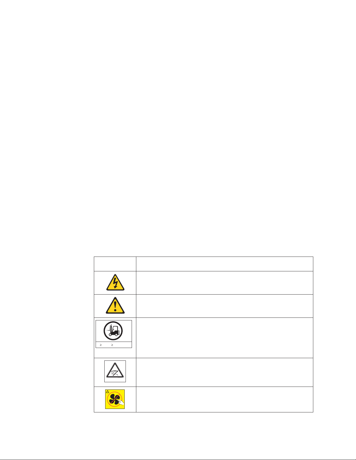
Caution notices
A caution notice calls attention to a situation that is potentially hazardous to people
because of some existing condition. A caution notice can be accompanied by
different symbols, as in the examples below:
If the symbol
is... It means....
A hazardous electrical condition with less severity than electrical danger.
A generally hazardous condition not represented by other safety symbols.
A specification of product weight that requires safe lifting practices. The
weight range of the product is listed below the graphic, and the wording
of the caution varies, depending on the weight of the device.
55 kg ( 121.2 lbs)
>55kg (121.2 lb)
P/N 18P5850-B
svc00169
A potential hazard of pinching the hand or other body parts between
parts.
SJ000752
A hazardous condition due to moving parts nearby.
xiv Ethernet Switch s-series Installation and User Guide
Page 17

If the symbol
is... It means....
A hazardous condition due to the use of a laser in the product. Laser
symbols are always accompanied by the classification of the laser as
defined by the U.S. Department of Health and Human Services (for
example, Class I, Class II, and so forth).
Read and comply with the following caution notices before installing or servicing this
device.
CAUTION:
Energy hazard present. Shorting may result in system outage and
possible physical injury. Remove all metallic jewelry before
servicing. (C001)
CAUTION:
The weight of this part or unit is between 32 and 55 kg (70.5 and
121.2 lb). It takes three persons to safely lift this part or unit. (C010)
32-55 kg (70.5-121.2 lbs)
svc00168
32-55 kg
(70.5-121.2 lb)
CAUTION:
The weight of this part or unit is more than 55 kg (121.2 lb). It takes
specially trained persons, a lifting device, or both to safely lift this
part or unit. (C011)
55 kg ( 121.2 lbs)
svc00169
>55kg (121.2 lb)
CAUTION:
This product is equipped with a 3-wire (two conductors and ground)
power cable and plug. Use this power cable with a properly
grounded electrical outlet to avoid electrical shock. (C018)
CAUTION:
Servicing of this product or unit is to be performed by trained
service personnel only. (C032)
Danger notices
A danger notice calls attention to a situation that is potentially lethal or extremely
hazardous to people. A lightning bolt symbol accompanies a danger notice to
represent a dangerous electrical condition. Read and comply with the following
danger notices before installing or servicing this device.
DANGER
To prevent a possible shock from touching two surfaces with
different protective ground (earth), use one hand, when possible,
to connect or disconnect signal cables. (D001)
Preface xv
Page 18

DANGER
Overloading a branch circuit is potentially a fire hazard and a
shock hazard under certain conditions. To avoid these hazards,
ensure that your system electrical requirements do not exceed
branch circuit protection requirements. Refer to the information
that is provided with your device or the power rating label for
electrical specifications. (D002)
DANGER
If the receptacle has a metal shell, do not touch the shell until
you have completed the voltage and grounding checks. Improper
wiring or grounding could place dangerous voltage on the metal
shell. If any of the conditions are not as described, STOP. Ensure
the improper voltage or impedance conditions are corrected
before proceeding. (D003)
DANGER
An electrical outlet that is not correctly wired could place
hazardous voltage on metal parts of the system or the devices
that attach to the system. It is the responsibility of the customer
to ensure that the outlet is correctly wired and grounded to
prevent an electrical shock. (D004)
The following general electrical danger notice provides instructions on how to avoid
shock hazards when servicing equipment. Unless instructed otherwise, follow the
procedures in this danger notice.
xvi Ethernet Switch s-series Installation and User Guide
Page 19

DANGER
When working on or around the system, observe the following
precautions:
Electrical voltage and current from power, telephone, and
communication cables are hazardous. To avoid a shock hazard:
v Connect power to this unit only with the IBM provided power
cord. Do not use the IBM provided power cord for any other
product.
v Do not open or service any power supply assembly.
v Do not connect or disconnect any cables or perform
installation, maintenance, or reconfiguration of this product
during an electrical storm.
v The product might be equipped with multiple power cords. To
remove all hazardous voltages, disconnect all power cords.
v Connect all power cords to a properly wired and grounded
electrical outlet. Ensure that the outlet supplies proper voltage
and phase rotation according to the system rating plate.
v Connect any equipment that will be attached to this product to
properly wired outlets.
v When possible, use one hand only to connect or disconnect
signal cables.
v Never turn on any equipment when there is evidence of fire,
water, or structural damage.
v Disconnect the attached power cords, telecommunications
systems, networks, and modems before you open the device
covers, unless instructed otherwise in the installation and
configuration procedures.
v Connect and disconnect cables as described below when
installing, moving, or opening covers on this product or
attached devices.
To Disconnect:
1. Turn off everything (unless instructed otherwise).
2. Remove the power cords from the outlets.
3. Remove the signal cables from the connectors.
4. Remove all cables from the devices.
To Connect:
1. Turn off everything (unless instructed otherwise).
2. Attach all cables to the devices.
3. Attach the signal cables to the connectors.
4. Attach the power cords to the outlets.
5. Turn on the devices.
(D005)
If the weight of the product is greater than 227 kg (500 lb), the following statement
and notice apply. This could apply if multiple products are installed in a single
cabinet, and that cabinet and products needs to be moved.
Preface xvii
Page 20
Delivery and subsequent transportation of the equipment: The customer
should prepare his environment to accept the new product based on the installation
planning information provided, with assistance from an IBM Installation Planning
Representative (IPR) or IBM authorized service provider. In anticipation of the
equipment delivery, the final installation site should be prepared in advance such
that professional movers/riggers can transport the equipment to the final installation
site within the computer room. If for some reason, this is not possible at the time of
delivery, the customer will need to make arrangements to have professional
movers/riggers return to finish the transportation at a later date. Only professional
movers/riggers should transport the equipment. The IBM authorized service provider
will only perform minimal frame repositioning within the computer room, as needed,
to perform required service actions. The customer is also responsible for using
professional movers/riggers in the case of equipment relocation or disposal.
DANGER
Heavy equipment—personal injury or equipment damage might
>(>)500 lbs. 227 kg.
result if mishandled. (D006)
a69i0333
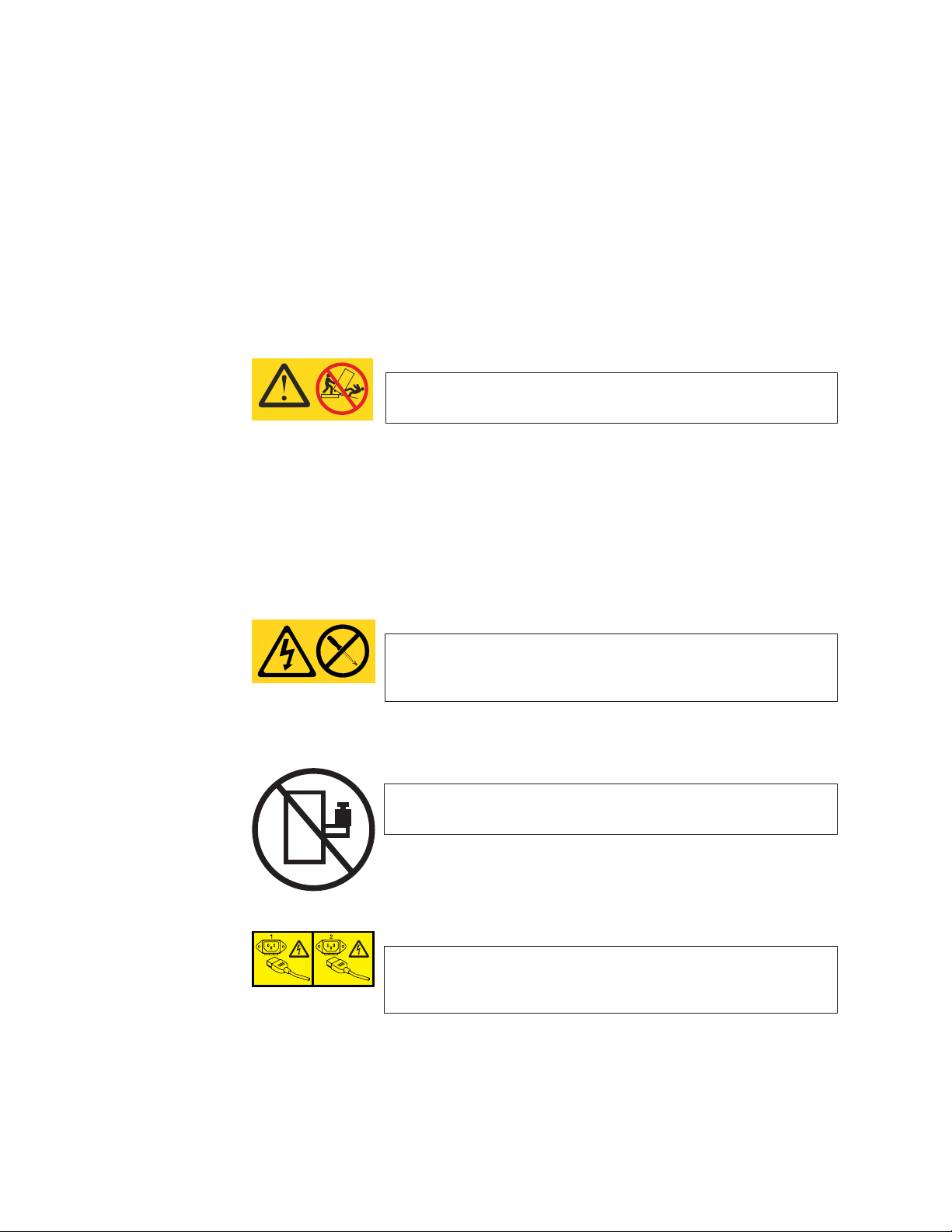
Safety labels
As an added precaution, safety labels are often installed directly on products or
product components to warn of potential hazards. These can be either danger or
caution notices, depending upon the level of the hazard.
The actual product safety labels may differ from these sample safety labels:
DANGER
Hazardous voltage, current, or energy levels are present inside
any component that has this label attached. Do not open any
cover or barrier that contains this label. (L001)
DANGER
Rack-mounted devices are not to be used as a shelf or work
space. (L002)
DANGER
Multiple power cords. The product might be equipped with
multiple power cords. To remove all hazardous voltages,
disconnect all power cords. (L003)
xviii Ethernet Switch s-series Installation and User Guide
Page 21

DANGER
Hazardous voltage present. Voltages present constitute a shock
hazard, which can cause severe injury or death. (L004)
CAUTION:
Hazardous energy present. Voltages with hazardous energy might
cause heating when shorted with metal, which might result in
splattered metal, burns, or both. (L005)
CAUTION:
Hazardous moving parts nearby (L008)
P/N 18P5850-B
CAUTION:
Pinch hazard. (L012)
SJ000752
Preface xix
Page 22

Rack safety
Rack installation
DANGER
Observe the following precautions when working on or around your IT rack system:
v Heavy equipment—personal injury or equipment damage might result if
mishandled.
v Always lower the leveling pads on the rack cabinet.
v Always install stabilizer brackets on the rack cabinet.
v To avoid hazardous conditions due to uneven mechanical loading, always install
the heaviest devices in the bottom of the rack cabinet. Always install servers and
optional devices starting from the bottom of the rack cabinet.
v Rack-mounted devices are not to be used as shelves or work spaces. Do not
place objects on top of rack-mounted devices.
v Each rack cabinet might have more than one power cord. Be sure to disconnect
all power cords in the rack cabinet when directed to disconnect power during
servicing.
v Connect all devices installed in a rack cabinet to power devices installed in the
same rack cabinet. Do not plug a power cord from a device installed in one rack
cabinet into a power device installed in a different rack cabinet.
v An electrical outlet that is not correctly wired could place hazardous voltage on
the metal parts of the system or the devices that attach to the system. It is the
responsibility of the customer to ensure that the outlet is correctly wired and
grounded to prevent an electrical shock.
(R001 part 1 of 2)
CAUTION:
v Do not install a unit in a rack where the internal rack ambient temperatures will
exceed the manufacturer’s recommended ambient temperature for all your
rack-mounted devices.
v Do not install a unit in a rack where the air flow is compromised. Ensure that air
flow is not blocked or reduced on any side, front, or back of a unit used for air flow
through the unit.
v Consideration should be given to the connection of the equipment to the supply
circuit so that overloading of the circuits does not compromise the supply wiring or
overcurrent protection. To provide the correct power connection to a rack, refer to
the rating labels located on the equipment in the rack to determine the total power
requirement of the supply circuit.
v (For sliding drawers) Do not pull out or install any drawer or feature if the rack
stabilizer brackets are not attached to the rack. Do not pull out more than one
drawer at a time. The rack might become unstable if you pull out more than one
drawer at a time.
v (For fixed drawers) This drawer is a fixed drawer and must not be moved for
servicing unless specified by the manufacturer. Attempting to move the drawer
partially or completely out of the rack might cause the rack to become unstable or
cause the drawer to fall out of the rack.
(R001 part 2 of 2)
xx Ethernet Switch s-series Installation and User Guide
Page 23

Rack relocation (19″ rack)
CAUTION:
Removing components from the upper positions in the rack cabinet improves
rack stability during relocation. Follow these general guidelines whenever you
relocate a populated rack cabinet within a room or building:
v Reduce the weight of the rack cabinet by removing equipment starting at
the top of the rack cabinet. When possible, restore the rack cabinet to the
configuration of the rack cabinet as you received it. If this configuration is
not known, you must do the following:
– Remove all devices in the 32U position and above.
– Ensure that the heaviest devices are installed in the bottom of the rack
cabinet.
– Ensure that there are no empty U-levels between devices installed in the
rack cabinet below the 32U level.
– If the rack cabinet you are relocating is part of a suite of rack cabinets,
detach the rack cabinet from the suite.
– Inspect the route that you plan to take when moving the rack to
eliminate potential hazards.
– Verify that the route that you choose can support the weight of the
loaded rack cabinet. Refer to the documentation that came with your
rack cabinet for the weight of a loaded rack cabinet.
– Verify that all door openings are at least 760 x 2030 mm (30 x 80 in.).
– Ensure that all devices, shelves, drawers, doors, and cables are secure.
– Ensure that the four leveling pads are raised to their highest position.
– Ensure that there is no stabilizer bracket installed on the rack cabinet
during movement.
– Do not use a ramp inclined at more than 10 degrees.
– Once the rack cabinet is in the new location, do the following:
- Lower the four leveling pads.
- Install stabilizer brackets on the rack cabinet.
- If you removed any devices from the rack cabinet, repopulate the rack
cabinet from the lowest position to the highest position.
– If a long distance relocation is required, restore the rack cabinet to the
configuration of the rack cabinet as you received it. Pack the rack
cabinet in the original packaging material, or equivalent. Also, lower the
leveling pads to raise the casters off of the pallet and bolt the rack
cabinet to the pallet.
(R002)
Product recycling and disposal
Refer to the IBM Systems Environmental Notices and User Guide (Z125-5823) on
the product documentation CD for translated environmental statements and
information regarding product recycling and disposal.
Preface xxi
Page 24

Product documents
The following documents contain information related to this product. The
documentation may be printed material or may be on the documentation CD that is
shipped with the product.
v IBM Ethernet Switch s-series Installation and User Guide, GC27-2243 (this
document)
v IBM Systems Safety Notices, G229–9054
v IBM Systems Environmental Notices and User Guide, Z125-5823
v IBM Ethernet Switch and Router 4002 and 4003 Statement of Limited Warranty,
GC27-2239
Software documents
IBM Ethernet switch and router products use software licensed from Brocade
Communications Systems, Inc. You can find software publications that support your
product on the CD-ROM supplied with this product.
The software publications associated with this product are:
v FastIron Configuration Guide
v IronWare MIB Reference
These publications reflect only the original Brocade products names. Use the
cross-reference of products in Table 1 to assist you when determining which
information in those publications applies to your product. Brocade products with no
IBM equivalents are not listed in the table. Note that the IBM products can be
ordered with additional features, while Brocade products with those additional
features may be offered as separate models.
Table 1. Comparable IBM and Brocade products.
IBM product
name
Ethernet Router
B04M
Ethernet Router
B08M
Ethernet Router
B16M
Ethernet Switch
B08S
Ethernet Switch
B16S
Ethernet Switch
B48C
IBM
machine
type
4003 M04 4U modular Ethernet router with 4
4003 M08 7U modular Ethernet router with 8
4003 M16 14U modular Ethernet router with 16
4003 S08 6U modular Ethernet switch with 8
4003 S16 14U modular Ethernet switch with 16
4002 C4A (4002AC4) 1U Ethernet switch with forty-eight
4002 C4B, (4002BC4) 1U Ethernet switch with forty-eight
IBM model
(HVEC model in
parentheses) Brief product description
Brocade product
name
NI-MLX-4-AC
interface slots
NI-MLX-8-AC
interface slots
NI-MLX-16-AC
interface slots
FI-SX800-AC
interface slots
FI-SX1600-AC
interface slots
NI-CES-2048C-AC
10/100/1000 Mbps RJ45 ports and 4
combination 100/1000 SFP Ethernet ports
NI-CES-2048F-AC
100/1000 SFP Ethernet ports
xxii Ethernet Switch s-series Installation and User Guide
Page 25

Table 1. Comparable IBM and Brocade products. (continued)
IBM product
name
Ethernet Switch
B50C
Ethernet Switch
B48G
Ethernet Switch
B50G
IBM
machine
type
4002 C5A, (4002AC5) 1U Ethernet switch with forty-eight
4002 C5B, (4002BC5) 1U Ethernet switch with forty-eight
4002 G4A, (4002AG4) 1.5U Ethernet switch with forty-eight
4002 G5A, (4002AG5) 1.5U stackable Ethernet switch with
IBM model
(HVEC model in
parentheses) Brief product description
10/100/1000 RJ45 ports and two 10G
XFP uplink ports
100/1000 SFP Ethernet ports and two
10G XFP uplink ports
10/100/1000 Mbps RJ45 ports and 4
combination 100/1000 SFP Ethernet ports
forty-eight 10/100/1000 Mbps RJ45 ports,
4 combination 100/1000 SFP Ethernet
ports, and a two port CX4 module
Getting help
For the latest version of your product documentation, visit the web at
www.elink.ibmlink.ibm.com/public/applications/publications/cgibin/pbi.cgi. Search by
form number or title.
Brocade product
name
NI-CES-2048CX-AC
NI-CES-2048FX-AC
FGS648P
FGS648P-STK
For more information about this and other IBM products, visit the IBM web site:
www.ibm.com/
For support information for this product and other IBM products, see the following
Web site: www.ibm.com/systems/support/. Select your product family, and follow the
web navigation to your specific product.
You can also contact IBM within the United States at 1-800-IBMSERV
(1-800-426-7378). For support outside the United States, you can find the service
number at: www.ibm.com/planetwide/.
Visit www.ibm.com/contact for the contact information for your country or region.
Taiwan Contact Information
IBM Taiwan Product Service Contact Info:
IBM Taiwan Corporation
3F, No 7, Song Ren Rd., Taipei Taiwan
Tel: 0800-016-888
Preface xxiii
Page 26

How to send your comments
Your feedback is important in helping us provide the most accurate and high-quality
information. If you have comments or suggestions for improving this document,
send us your comments by e-mail to starpubs@us.ibm.com or use the Readers’
Comments form at the back of this publication. Be sure to include the following:
v Exact publication title
v Form number (for example, GC26-1234-02)
v Page numbers to which you are referring
If the Reader Comment Form in the back of this manual is missing, you can direct
your mail to:
International Business Machines Corporation
Information Development
Department GZW
9000 South Rita Road
Tucson, Arizona 85744-0001 U.S.A.
When you send information to IBM, you grant IBM a nonexclusive right to use or
distribute the information in any way it believes appropriate without incurring any
obligation to you.
xxiv Ethernet Switch s-series Installation and User Guide
Page 27

Chapter 1. About This Guide
This guide includes procedures for installing the hardware and configuring essential
parameters such as permanent passwords and IP addresses for the IBM Ethernet
Switch B08S and B16S products. The basic software configuration procedures
show how to perform tasks using the CLI. This guide also includes instructions for
managing and maintaining the hardware. For a summary of installation tasks see
Table 13 on page 27.
Audience
This guide is designed for network installers, system administrators, and resellers
who install the hardware. This guide assumes a working knowledge of Layer 2 and
Layer 3 switching and routing concepts.
Nomenclature
This guide uses the following typographical conventions to show information:
Italic highlights the title of another publication and occasionally emphasizes a word
or phrase.
Bold highlights a CLI command.
Bold Italic highlights a term that is being defined.
© Copyright IBM Corp. 2009 1
Page 28

2 Ethernet Switch s-series Installation and User Guide
Page 29

Chapter 2. Product Overview
This chapter contains an overview of the IBM Ethernet Switch B08S and B16S
Layer 2 and Layer 3 switches. Designed for medium to large enterprise backbones,
these devices are modular switches that provide the enterprise network with a
complete end-to-end Enterprise LAN solution, ranging from the wiring closet to the
LAN backbone.
Through the remainder of this guide, these products will be referred to as the B08S
and the B16S. When reference to a specific model is not required, the general
terms switch, product, or device will be used to refer to all the models. The term
s-series may also be used to collectively refer to these switch products.
Hardware benefits
The s-series switches provide the following benefits:
v The management module is non-blocking, with a adjustable switch fabric module
and twelve combination Gigabit Ethernet (GbE) copper or fiber ports that provide
connectivity to your existing management network.
v The management modules have a console port and a 10/100/1000 port that
provide connectivity to your existing management network. The management
modules optionally support 2-port 10-GbE ports or 8-port GbE fiber and copper
ports.
v The management modules are interchangeable between the IBM Ethernet Switch
s-series models. However, you cannot mix IPv4 and IPv6 modules together in the
same chassis.
v Optional dual management modules provide 100% redundancy.
v The crossbar (xbar) architecture enables the management module to switch 30
Gigabits per second between each interface module and within the management
module.
v The interface modules and power supplies are interchangeable between the IBM
Ethernet Switch s-series models. However, you cannot mix IPv4 and IPv6
modules together in the same chassis.
v The management, switch fabric, and interface modules are hot swappable, which
means you can remove and replace them while the chassis is powered on and
running.
v The devices have a passive backplane.
v Completely separate data and control planes, which results in uncompromised
switching performance, increased reliability of both planes, and increased
security of the control plane in the event of a Denial of Service (DoS) attack on
the data plane.
v Distributed data and control planes, which results in uncompromised wire-speed
performance for the data plane and faster and more efficient performance of
management functions for the control plane.
© Copyright IBM Corp. 2009 3
Page 30
POE port density
Table 2 details the maximum number of POE class 3 (15.4W) ports allowed per
power supply used.
Table 2. Maximum number of POE class 3 (15.4W) ports per power supply
Power Supply
1250 W 1 70 70
1250 W 2 140 140
1250 W 3 N/A 210
1250 W 4 N/A 280
2500W 220V POE Power Supply 1 140 140
2500W 220V POE Power Supply 2 280 280
2500W 220V POE Power Supply 3 N/A 420
2500W 220V POE Power Supply 4 N/A 560
Note: B08S supports a maximum of 192 POE ports. The B16S supports a
Number of
Power
Supplies B08S B16S
maximum of 384 POE ports.
Supported configurations
Standard devices support Layer 2 and base Layer 3 switching. All standard devices
can be upgraded to full Layer 3 multiprotocol routing through the purchase of an
upgrade feature, at which time they are considered to be premium devices.
The IBM Ethernet Switch s-series can be configured with either all IPv4
management and IPv4 interface modules, or all IPv6 management and IPv6
interface modules. You cannot mix IPv4 and IPv6 modules within a chassis.
Depending on the type of management module installed in the device, IPv6
premium devices support either:
v IPv4 multiprotocol routing and IPv6 host and management features, or
v IPv6 and IPv4 multiprotocol routing and IPv6 host and management features
The devices optionally support Power over Ethernet (POE), providing the means for
integrating data, voice, and video over existing Ethernet cables.
Table 3. Configurations supported on the devices
Power over Ethernet
Device Standard Premium
B08S Yes Yes Yes
B16S Yes Yes Yes
(POE)
Software features
Software features differ depending on the software version that is loaded on the
device and the type of management module that is installed in the chassis. See the
Configuration Guide for a complete list of software features supported on your
device.
4 Ethernet Switch s-series Installation and User Guide
Page 31

Power over Ethernet (POE) applications
B08S and B16S devices with Power over Ethernet (POE) are compliant with the
standards described in the IEEE 802.3af specification for delivering in-line power.
The 802.3af specification defines the standard for delivering power over existing
network cabling infrastructure, enabling multicast-enabled full streaming audio and
video applications for the following converged services:
v Voice over IP (VoIP)
v WLAN access points
v IP surveillance cameras
v IP technology devices
POE technology eliminates the need for an electrical outlet and dedicated UPS near
IP powered devices. With POE power sourcing devices, power is consolidated and
centralized in the wiring closets, improving the reliability and resiliency of the
network. Because POE can provide power over Ethernet cable, power is
continuous, even in the event of a power failure.
For POE port density, see “POE port density” on page 4.
For more information about POE and how to configure it, see the Configuration
Guide.
Support for IPv6 modules
The B08S and B16S support IPv6 management and interface modules starting with
software release 04.0.00.
For details about IPv6 modules, see the following sections in this chapter:
v “IPv6 hardware support guidelines”
v “Hardware features”
v “Interface modules” on page 13
IPv6 hardware support guidelines
Note the following guidelines and restrictions with IPv6 Management and Interface
modules:
v IPv4 interface modules must only be matched with IPv4 management modules
and IPv4 interface modules within the same chassis.
v If you install dual IPv6 management modules, the modules must be identical. For
example, you cannot install one 2-port management module and one 8-port
management module together in the same chassis. The modules must be of
like-kind.
Hardware features
The s-series switches include the following major hardware components:
v Chassis
v Management module with optional support for dual management modules that
provide 100% redundancy
v Separate switch fabric modules
v Interface modules
Chapter 2. Product Overview 5
Page 32

B08S
v Power supplies
v Fan tray in the B08S composed of six five-speed fans and a fan control module
v Air filter in the bottom front of the B16S chassis and two fan trays at the rear of
the chassis
v Adjustable mounting brackets on the B08S The B16S has adjustable mounting
brackets.
The following sections provide more information about these components.
For details about physical dimensions, power supply specifications, and pinouts,
see Chapter 8, “Hardware specifications,” on page 121.
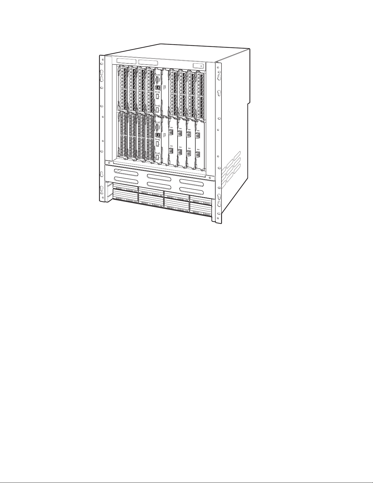
The B08S is 6 rack units in height and consists of the following:
v Two half slots for the management modules
v Two half slots for the switch fabric modules
v Eight half slots for the interface modules
v Four slots for power supplies along the bottom of the card shelf. The power
supply slots add an additional rack unit (RU) to the height of the chassis.
Figure 1 shows the B08S
Figure 1. B08S
The B08S ships from the factory with the following components installed:
v Two switch fabric modules
v A slot panel in each interface module slot and power supply slot that does not
currently have a module or power supply installed in it. The slot panel ensures
proper airflow within the chassis.
v One AC System power supply (SYS)
v A fan tray assembly which contains the cooling system for the chassis
6 Ethernet Switch s-series Installation and User Guide
net08bs003
Page 33

In the B08S slots, you can install the following:
v Up to two management modules
v Up to eight interface modules
v Up to four AC power supplies: two System (SYS) power supplies and two Power
over Ethernet (POE) power supplies
Before installing any modules or power supplies, you must remove the slot panel.
Attention: If you do not install a module in a slot, you must keep the slot panel in
place. If you run the chassis with an uncovered slot, the system will overheat.
Figure 2 shows the B08S and the slots into which you can install the various
modules and power supplies.
Slot 1 Slot 2 FanTray
B16S
F1
424C
F1
Slot 3 Slot 4
Slot 5
Slot 7
Slot 9
Switch
Fabr ic
424C
F1
424C
F1
424C
10/100/1000
Console
Pwr
Active
Ethernet
Pwr
Active
Slot 1
AC OKDC OKALM
EJECT POE
AC OKDC OKALM
EJECT POE
F1
424C
F1
424C
F1
424C
F1
424C
10/100/1000
Console
Pwr
Active
Ethernet
Pwr
Active
Slot 6
Slot 8
Slot 10
Switch
Fabric
Slot 2
AC OKDC OKALM
EJECT SYS
AC OKDC OKALM
EJECT SYS
ESD Connector
Figure 2. B08S slots
Figure 2 also shows an electrostatic discharge (ESD) connector, into which you can
plug an ESD wrist strap to ground yourself while handling and installing modules.
CAUTION:
For safety reasons, the ESD wrist strap should contain a series 1 meg ohm
resistor.
net08bs004
The IBM B16S is a 14 rack unit and consists of the following:
v Two half slots for the management modules
v Two half slots for the switch fabric modules
v Sixteen half slots for the interface modules
v Eight slots for power supplies along the bottom of the card shelf.
Figure 3 on page 8 shows the front of the B16S.
Chapter 2. Product Overview 7
Page 34
net08bs005
Figure 3. B16S
Units shipped from the factory have the following components installed in the
chassis:
v Two switch fabric modules
v A slot panel in each interface module slot and power supply slot that does not
currently have a module or power supply installed in it. The slot panel ensures
proper airflow within the chassis.
v Two AC System power supplies (SYS)
v A fan tray assembly which contains the cooling system for the chassis
In the chassis slots, you can install the following:
v Up to two management modules
v Up to 16 interface modules
v Up to eight AC power supplies: four System (SYS) power supplies and four
Power over Ethernet (POE) power supplies
Before installing any modules or power supplies, you must remove the slot panel.
Attention: If you do not install a module in a slot, you must keep the slot panel in
place. If you run the chassis with an uncovered slot, the system will overheat.
Figure 4 on page 9 shows the chassis slots into which you can install the various
modules and power supplies. It also shows an electrostatic discharge (ESD)
connector, into which you can plug an ESD wrist strap to ground yourself while
handling and installing modules.
8 Ethernet Switch s-series Installation and User Guide
Page 35

CAUTION:
For safety reasons, the ESD wrist strap should contain a series 1 meg ohm
resistor.
Switch Fabric
Mgmt
Slot 1
Slot 9
Interface
Slot 1
Interface
Slot 3
Interface
Slot 5
Interface
Slot 7
Interface
Slot 11
Active
Pwr
Active
Pwr
Interface
Slot 13
Interface
Slot 15
Interface
Slot 17
ESD
Connector
Interface
Slot 2
Figure 4. B16S chassis slots
Management modules
This section describes the management modules for the devices. The B08S and
B16S each require one management module and optionally support two
management modules for 100% redundancy. Each management module occupies
one half slot.
AC OKDC OKALM
Interface
Slot 4
EJECT SYS
Interface
Slot 6
AC OKDC OKALM
Mgmt
Slot 10
Interface
Slot 8
EJECT SYS
Switch
Fabric
Slot 2
Interface
Slot 12
Interface
Slot 14
net08bs006
Interface
Slot 16
Interface
Slot 18
Chapter 2. Product Overview 9
Page 36

B08S and B16S management modules
The management modules for the B08S and B16S are interchangeable between
devices. Standard management modules provide Layer 2 and base Layer 3
functionality only.
Note: Premium management modules support full Layer 3 functionality.
v The IBM Ethernet Switch B08S and B16S management modules are
interchangeable with each other, and are only supported on these chassis
models.
v You cannot intermix different management modules in the same chassis. For
example, if you have an IPv4 2-port 10 GbE Management Module installed in a
chassis, you must match it with another IPv4 2-port 10 GbE Management Module
within that chassis.
v You cannot mix IPv6 and IPv4 modules in the same chassis. A chassis must
contain either all IPv4 management and IPv4 interface modules, or all IPv6
management and IPv6 interface modules.
Table 4 lists the management modules for the B08S and B16S.
Table 4. Details regarding the management modules for the B08S and B16S
Management Modules Description
IPv4 management modules
Management Module (IPv4) no ports
Management Module 10 GbE
(IPv4)
IPv6 management modules
Management module 10 GbE
(IPv6)
two 10-GbE ports
Contains two 10 GbE ports for network connectivity
512 MB SDRAM enables support for large routing tables (1,000,000 BGP routes)
with the full Layer 3 code.
The B08S and B16S management modules perform the following tasks:
v Control the hardware components
v Control the separate switch fabric modules
v Run the networking protocols
v Provide the real time operating system
B08S management modules are located in slots 9 and 10, just above the switch
module slots; see Figure 2 on page 7.
B16S management modules are located in slots 9 and 10 along the center of the
chassis; see Figure 4 on page 9.
Figure 5 on page 11 shows the front panel of the IPv4 management modules with
no ports.
10 Ethernet Switch s-series Installation and User Guide
Page 37

Pw r
Console
10/100/1000
Acti ve
Ethernet
net08bs011
Figure 5. B08S and B16S management module with no ports
Figure 6 shows the front panel of the IPv4 management modules with two 10-GbE
ports.
Console
Pw r
Acti ve
Figure 6. B08S and B16S management module with two 10-GbE ports
10/100/1000
Ethernet
Link
Act
12
Link
Act
net08bs012
The front panel on the management modules include the following control features:
v A console port and 10/100/1000 RJ-45 copper port allow you to access the
system’s CLI directly from a PC or terminal or via a Telnet connection to the PC
or terminal.
v Depending on the type of management modules installed in the device, the
management modules have the following ports:
– no 10-GbE fiber ports
– two 10-GbE fiber ports
v LEDs for power and active/standby status
v Four LEDs for the two 10-GbE fiber ports (2-port 10-GbE modules only)
v A recessed reset button
10/100/1000 GbE copper port on the B08S and B16S management modules
The 10/100/1000 RJ-45 copper port on the management module enables you to
attach a PC or terminal. From this Ethernet port, you can access the system’s CLI
or Web management interface directly from the PC or terminal or via a Telnet
connection to the PC or terminal.
10-GbE ports on the B08S and B16S 2-port 10-GbE management modules
The B08S and B16S 2-port 10-GbE management modules come with two 10-GbE
fiber ports through which you can connect your device to other network devices at a
speed of 10 Gigabits per second.
The 10-GbE ports support 10-Gigabit Small form Factor Pluggable (XFP)
MSA-compliant transceivers. The transceivers support the fiber optic cabling for
LAN PHY.
LEDs on the B08S and B16S management modules
The management modules provide status information using the LEDs listed in
Table 5 on page 12.
Chapter 2. Product Overview 11
Page 38

Table 5. LED status information for B08S and B16S management modules
LED Description and position State Meaning
Pwr Round LED located to the left
of the console port
Active Round LED located to the left
of the console port
10/100/1000 Copper Port LEDs
Lnk Left-most LED above the port On The port is connected.
Act Right-most LED above the port. On or
10-GbE Port LEDs
Lnk Top-most LED to the left of the
port.
Act Bottom-most LED to the left of
the port.
On
(Green)
Off The module is not receiving
On
(Green)
Off The module is not the active
Off No port connection exists.
Blinking
Off The port is not transmitting or
On Fiber port is connected.
Off No Fiber port connection exists.
On or
Blinking
Off The port is not transmitting or
The module is receiving power.
power.
The module is the active
management module.
management module.
The port is transmitting and
receiving traffic.
receiving traffic.
The port is transmitting and
receiving traffic.
receiving traffic.
Console port
The console port on the management module is a standard DB-9 serial connector
through which you can attach a PC or terminal to configure the system using the
command line interface (CLI).
The console port interfaces the control plane only and not the data plane.
Reset button
The reset button on the management module allows you to restart the system. The
reset button is recessed to prevent it from being pushed accidentally.
The reset button is located next to the console port on the management module.
Switch fabric modules
The switch fabric modules switch user packets from one interface module installed
in the chassis to another. The switch fabric modules in the B08S and B16S are
separate from the management modules and are physically located next to the
management modules.
Figure 7 on page 13 shows the B08S and B16S switch fabric module.
12 Ethernet Switch s-series Installation and User Guide
Page 39

Pw r
Acti ve
Figure 7. B08S and B16S switch fabric module
LEDs on the switch fabric module
The front panel provides status information using the LEDs listed in Table 6.
Table 6. Front panel switch fabric LED status
LED Description and Position State Meaning
Pwr Top-most LED On (Green) The module is receiving power.
Active Bottom-most LED On (Green) The module is functioning properly.
Interface modules
This section describes the interface modules for the following:
v The B08S, in which you can install up to eight Interface modules in the slots
shown in Figure 2 on page 7.
v The B16S, n which you can install up to 16 interface modules in the slots shown
in Figure 4 on page 9.
net08bs014
Off The module is not receiving power.
Off The module is not functioning properly.
Note: You cannot mix IPv4 and IPv6 modules together in the same chassis.
Table 7 lists the supported Interface modules for each type.
Table 7. Interface modules
Interface Module B08S B16S
IPv4 Interface Modules
24-port 10/100/1000 Mbps Ethernet RJ45 copper without POE X X
24-port 100/1000 Mbps Ethernet SFP
2-port 10 Gbps Ethernet XFP X X
IPv6 Interface Modules
IPv6 24-port 10/100/1000 Mbps Ethernet RJ45 copper without POE X X
IPv6 24-port 100/1000 Mbps Ethernet SFP X X
IPv6 2-port 10 Gbps Ethernet XFP X X
XX
Hot swap support
The B08S and B16S support Multi-Service IronWare R05.0.00a and later. Enhanced
Hot Swap is supported, meaning you can remove and replace the interface
modules without powering down the system, and without executing the disable
module command. However, it is recommended that the modules be disabled
through the CLI before removal from the chassis.
Chapter 2. Product Overview 13
Page 40
Attention: It is important to wait a minimum of 10 seconds between the removal
and insertion of a line module. Re-insertion of a line module less than 10 seconds
after the removal of a line module may result in the line module not being properly
recognized.
See “Replacing an interface module” on page 97 for instructions.
24-port 10/100/1000 Mbps Ethernet RJ45 copper interface module
The 24-port 10/100/1000 Mbps Ethernet RJ45 copper interface module has
twenty-four 10/100/1000 ports with RJ-45 connectors for Cat5 cabling. The copper
ports support automatic MDI/MDIX detection, and use auto-sensing and
auto-negotiating to determine the speed (10, 100, or 1000 Mbps) and duplex mode
(full-duplex or half-duplex) of the port at the other end of the link, and adjust the
port accordingly. Ports operating at 1000 Mbps operate in the full-duplex mode only
and cannot be modified.
This interface module supports Power over Ethernet (POE). You can order an
upgrade kit for your 24-port 10/100/1000 Mbps Ethernet RJ45 copper interface
module that includes a POE daughter card that is installed onto the module. To run
POE on your system, at least one 48-volt POE power supply must also be installed
in the chassis. See “Installing or replacing a POE daughter card” on page 102.
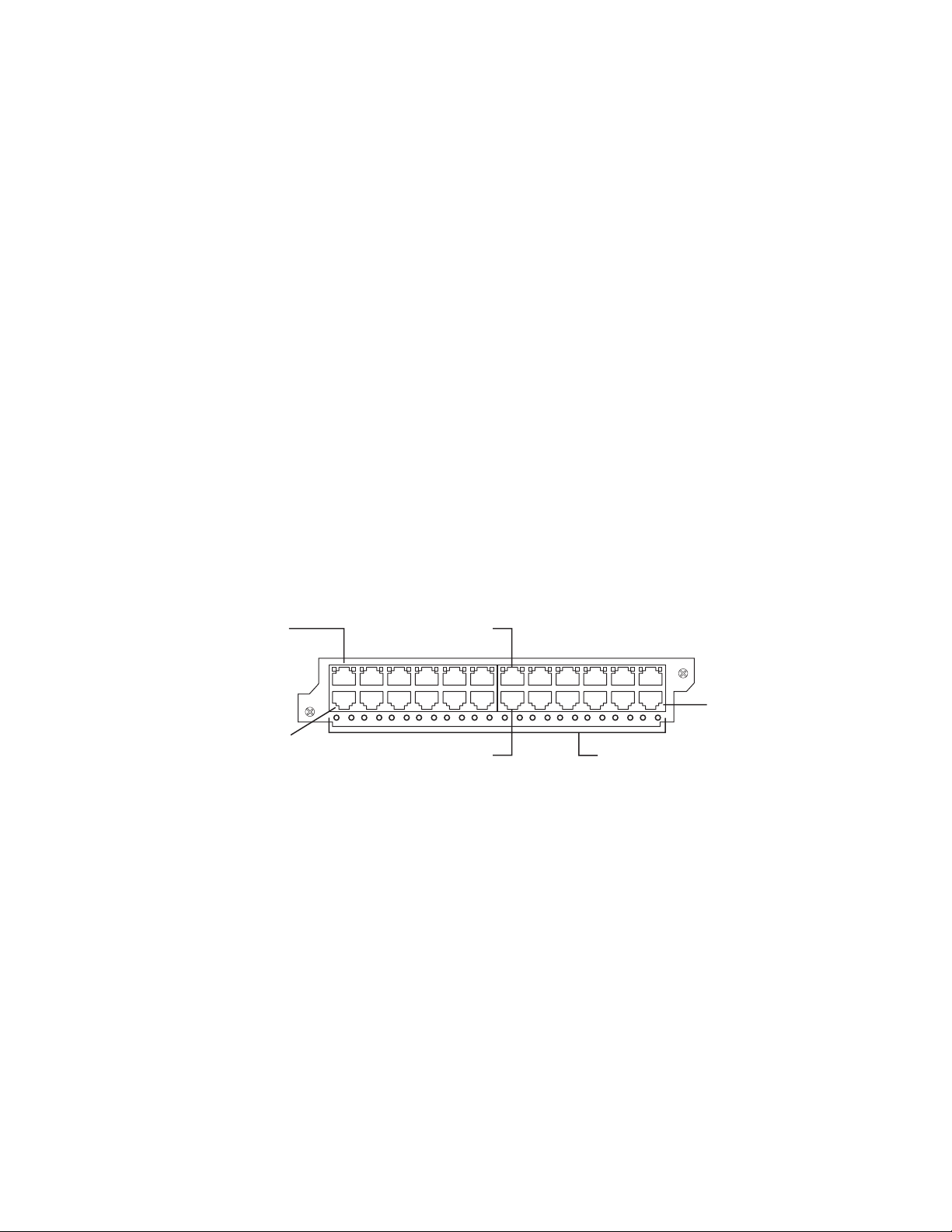
Figure 8 shows the front panel of the IPv4 24-port Gigabit Ethernet copper module.
The IPv6 24-port Gigabit Ethernet copper looks identical except for the 624C label
on the left edge.
Port 1
424C
Port 2
Figure 8. IPv4 24-port Gigabit Ethernet copper module front panel
Port 13
Port 14 POE LEDs
Port 24
net08bs015
The front panel includes the following control features:
v 24 10/100/1000 copper ports
v 24 LEDs for port status
v 24 LEDs for Power over Ethernet (POE) status
Note: The POE LEDs work only when POE is enabled on your device.
LEDs for 24-port 10/100/1000 Mbps Ethernet RJ45 copper interface module
The front panel of the 24-port Gigabit Ethernet copper module includes 24 LEDs
that indicate the status of each port, and 24 LEDs (on bottom) that indicate the
status of POE.
Note: The POE LEDs work only when POE is enabled on your device.
The copper ports also provide status information using the LEDs.
14 Ethernet Switch s-series Installation and User Guide
Page 41

Table 8. LEDs for 10/100/1000 copper ports
LED Position State Meaning
Link/Activity Square LED located on upper
left corner of upper copper
connector for upper copper
connector
Square LED located on upper
right corner of upper copper
connector for lower copper
connector
POE (if applicable) Round LED located beneath the
copper ports
The first (left-most) LED is for
port 1, the second LED is for
port 2, the third LED is for port
3, etc.
On (Green) A link is established with the remote
port.
Blinking The port is transmitting and receiving
traffic.
Off A link is not established with the
remote port.
On (Green) The port is enabled, a
power-consuming device has been
detected, and the module is supplying
power to the device.
Off The port is not providing in-line power.
24-port 100/1000 Mbps Ethernet hybrid fiber (SFP) interface module
The 24-port 100/1000 Mbps Ethernet hybrid fiber (SFP) interface module has 24
ports with connectors for Small form Factor Pluggable (SFP) Multisource Agreement
(MSA)-compliant transceivers.
Figure 9 shows the IPv4 100/1000 hybrid fiber interface module’s front panel. The
IPv6 100/1000 hybrid fiber interface module appears the same as the IPv4 module
except the label on the left end reads ″SX 624HF″ instead of ″SX 424HF".
Port 1
SX
424HF
Port 2
Figure 9. IPv4 100/1000 Hybrid Fiber interface module
Port 13
LEDs
Port 24
net08bs018
The front panel includes the following control features:
v 24 Gigabit Ethernet fiber ports
v 24 LEDs
The ports on the 24-port 100/1000 Gigabit Ethernet Hybrid Fiber module operate at
a fixed speed of 100 or 1000 Mbps (they do not support 10 Mbps connections), and
use auto-negotiation to automatically configure the highest performance mode of
inter-operation with the connected device.
Only supported Brocade-branded fiber-optic transceivers can be used in these
products. The SFP-compliant fiber-optic modules provide an optical transceiver or
physical medium dependent (PMD) interface for single or multi-mode fiber that can
Chapter 2. Product Overview 15
Page 42

be used with the LAN physical layer (PHY) and support optical monitoring
capabilities. Types of Brocade-branded SFP transceivers for the 100/1000 1 GbE
(SFP) interface modules include:
v 1000BaseT SFP Copper, 1 Gbps up to 100 m over CAT5 or higher cabling,
RJ-45 connector
v 1000Base SX 850 nm SFP optic, 1 Gbps up to 550 m over multi-mode fiber, LC
connector
v 1000Base LX 1310 nm SFP optic, 1 Gbps up to 10 km over single-mode fiber,
LC connector
v 1000Base LHA 1550 nm SFP optic, 1 Gbps up to 70 km over single-mode fiber,
LC connector
The slots support the 100Base and 1000Base fiber cabling listed in “Network
interfaces” on page 17.
Support for 100Base-FX on the 100/1000 interface module
The 24-port 100/1000 fiber interface module supports the 100Base FX 1310 nm
SFP optic, 100 Mbps up to 2 km over multi-mode fiber, LC connector.
To enable support for 100BaseFX, enter the CLI command at the interface level of
the CLI. For CLI command details, see the section regarding ″Enabling and
Disabling Support for 100BaseFX″ in the Configuration Guide.
2-port 10-Gigabit Ethernet interface modules
The 2-port 10-Gigabit Ethernet modules contain two physical ports, through which
you can connect the IBM device to other network devices at a speed of 10 Gigabits
per second.
Only supported Brocade-branded fiber-optic transceivers can be used in this
product. The XFP-compliant fiber-optic modules provide an optical transceiver or
physical medium dependent (PMD) interface for single or multi-mode fiber that can
be used with the LAN physical layer (PHY), and support optical monitoring
capabilities. Types of Brocade-branded XFP transceivers for the 10 GbE interface
modules include:
v Short Reach, 850 nm serial pluggable XFP optic, 10 Gbps up to 300 m over
multi-mode fiber, LC connector
v Long Reach, 1310 nm serial pluggable XFP optic, 10 Gbps up to 10 km over
single-mode fiber, LC connector
v Extended Reach, 1550 nm serial pluggable XFP optic, 10 Gbps up to 40 km over
single-mode fiber, LC connector
v 10 Base CX4, XFP transceiver, 10 Gbps up to 15 km, CX connector
Figure 10 shows the IPv4 2-port 10-Gigabit Ethernet module’s front panel.
42XG
Figure 10. IPv4 2-port 10-Gigabit Ethernet module’s front panel
Lnk
Act
1
Lnk
Act
2
net08bs020
16 Ethernet Switch s-series Installation and User Guide
Page 43

The IPv6 version has an identical appearance, except for the label on the left side,
which reads 62XG.
LEDs for 2-port 10-Gigabit Ethernet module
The 10 Gbps ports provide status information using the LEDs . This chapter
highlights the meanings and appearance of the LED on the 2-port 10-Gigabit
Ethernet module.
Table 9. LED on the 2-port 10-Gigabit Ethernet module
LED Position State Meaning
Lnk Top left of connector On Fiber port is connected.
Act Bottom left of
Network interfaces
Table 10 lists the network interfaces supported on the devices.
The output of the show media command displays the type of media installed in the
ports.
connector
Off No fiber port connection
exists.
On or Blinking The port is transmitting and
receiving traffic.
Off The port is not transmitting or
receiving traffic.
Table 10. Network interfaces
Interface Show Media Description
1000Base-LHA M-LHA
1000Base-LX M-LX
1000Base-SX M-SX
1000Base-T M-C
100Base-FX M-FX, M-FXB1, or M-FXB2
10GBase-CX4 XG-CX4
10GBase-ER XG-ER
10GBase-LR XG-LR
10GBase-SR XG-SR
¹ xxxx denotes the wavelength; for example, C1550.
² Supported on copper ports only.
Port regions
Ports on the devices are grouped into regions. For a few features, such as port
monitoring and unknown unicast configurations, you will need to know the region to
which a port belongs. However, for most features, a port’s region does not affect
configuration or operation of the feature. If a port’s region does affect configuration
or operation of a feature, it is noted and described in the appropriate feature section
of this guide.
v B08S and B16S management module with 2-port 10-GbE
– Port 1
Chapter 2. Product Overview 17
Page 44

Power supplies
– Port 2
v 24-port Gigabit Ethernet Copper interface module
– Ports1-12
– Ports 13 - 24
v 24-port Gigabit Ethernet Fiber interface module
– Ports1-12
– Ports 13 - 24
v 2-port 10-Gigabit Ethernet Fiber interface module
– Port 1
– Port 2
The ships with one or two power supplies, depending on how it was ordered from
the factory.
v The B08S comes with one 12-volt AC System (SYS) power supply. You can
install up to four power supplies in the B08S; two 12-volt AC system (SYS) power
supplies and two 48-volt AC power supplies for POE.
v The B16S comes with two 12-volt AC System (SYS) power supplies. You can
install up to eight power supplies in the B16S; four 12-volt AC system (SYS)
power supplies and four 48-volt AC power supplies for POE.
You can use any combination of the supported AC supplies in the same device.
Note the following regarding POE power supplies:
v The 2500W 220V POE Power Supply requires 220-volt input.
v The 2500W 220V POE Power Supply powers up to 140 class 3 POE ports,
therefore, the 90-240 VAC POE is not sufficient as a backup power supply.
Table 11. Power supplies supported in the devices
Sales Model Number Description B08S B16S
90-240 VAC SYS 12-volt AC
replacement power
supply
12-volt AC original
power supply
1250 W 90-240 VAC
POE
2500W 220V POE
Power Supply
48-volt AC
replacement power
supply
48-volt AC original
power supply
48-volt AC
(220-volt input only)
Supported Supported
Supported Supported
Supported Supported
Supported Supported
Supported Supported
To read more about the differences between replacement and original power
supplies, see “About replacement power supplies” on page 21.
Note: Manufacturing part numbers are inscribed on the labels on the top of the
power supply.
The following power supplies can be installed in the devices:
18 Ethernet Switch s-series Installation and User Guide
Page 45

v Non-POE devices:
– The 12-volt AC power supplies (also called system (SYS) power supplies)
provide power to one management module and up to eight non-POE interface
modules. In the B08S, you can install a second 12-volt power supply for
redundancy. The B16S comes with and requires two 12-volt power supplies
and supports up to four 12-volt power supplies for redundancy.
v POE devices:
– The 12-volt AC power supplies (also called system (SYS) power supplies)
provide power to the management module, all non-POE interface modules (if
applicable), and all ports on POE modules that do not require POE power or
to which no power-consuming devices are attached. In the B08S you can
install a second 12-volt power supply for redundancy. The B16S comes with
and requires two 12-volt power supplies and supports up to four 12-volt power
supplies for redundancy.
– The 1250 W 48-volt POE power supplies provide power to the POE daughter
card, and ultimately to POE power-consuming devices. The number of POE
power-consuming devices that one 48-volt power supply can support depends
on the number of watts required by each power-consuming device. Each
48-volt power supply can provide a maximum of 1080 watts of POE power,
and each POE port supports a maximum of 15.4 watts of power per POE
power-consuming device. for example, if each POE power-consuming device
attached to the IBM device consumes 15.4 watts of power, one 48-volt supply
will power up to 70 POE ports. You can install a second 48-volt supply for
additional POE power.
– The 48-volt (220-volt input only) POE power supplies provide power to the
POE daughter card, and ultimately to POE power-consuming devices. The
number of POE power-consuming devices that one 220-volt power supply can
support depends on the number of watts required by each power-consuming
device. Each 220-volt power supply can provide a maximum of 2160 watts of
POE power, and each POE port supports a maximum of 15.4 watts of power
per POE power-consuming device. For example, if each POE
power-consuming device attached to the device consumes 15.4 watts of
power, one 220-volt supply will power up to 140 POE ports. You can install a
second 220-volt supply for additional POE power.
Note: The system powers on as many POE ports as the 48-volt POE power
supplies can handle. The system calculates the maximum number of POE
ports it can support based on the number of POE power supplies installed.
POE ports are enabled based on their priority settings. Keep in mind that the
system will reserve the maximum configured power per POE-enabled port,
even if the POE power-consuming device is drawing less power.
Attention: The POE power supply is designed exclusively for use with the B08S
and B16S devices. The power supply produces extensive power to support 802.3af
applications. Installing the power supply in a device other than the ones
documented here will cause extensive damage to your equipment.
All power supplies are auto-sensing and auto-switching.
The power supplies are installed in the slots along the bottom of the chassis.
In the B08S the 12-volt (system) power supplies occupy slot numbers 3 and 4 on
the right, with the redundant supply in slot 4. The POE power supplies occupy slot
numbers 1 and 2 on the left. Figure 11 on page 20 shows power supply placement.
Chapter 2. Product Overview 19
Page 46
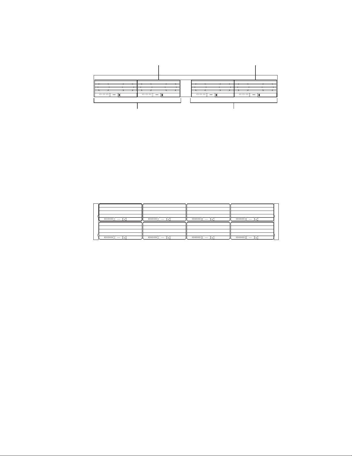
2nd POE
Power Supply in
Slot 2
Redundant SYS (12V)
Power Supply in
Slot 4
DC OK ALMAC OK DC OK ALMAC OK DC OK ALMAC OK DC OK ALMAC OK
POE Power Supply Slots SYS (12V) Power Supply Slots
POEEJECTPOEEJECT SYSEJECT SYSEJECT
net08bs022
Figure 11. Power supply placement in the B08S
In the B16S, the system power supplies occupy slot numbers1-4inthetoprow
with the redundant supplies in slot numbers 3 and 4. The POE power supplies
occupy slot numbers5-8inthebottom row. Figure 12 shows power supply
placement.
SYS (12V) Power Supplies
in Slot 1 and Slot 2
1
AC OKDC OKALM
AC OKDC OKALM
EJECT SYS
EJECT POE
AC OKDC OKALM
AC OKDC OKALM
5
2
EJECT SYS
EJECT POE
6
Redundant 12V Power Supplies
in Slot 3 andSlot 4
AC OKDC OKALM
AC OKDC OKALM
3
EJECT SYS
EJECT POE
7
AC OKDC OKALM
AC OKDC OKALM
4
EJECT SYS
EJECT POE
8
POE Power Supplies
in Slots 5 - 8
net08bs023
Figure 12. Power supply placement in the B16S
The installed power supplies provide power to all chassis components, sharing the
workload equally. If a power supply fails or overheats, the failed power supply’s
workload is redistributed to the redundant power supply, if one is present.
The power supplies are hot swappable, which means you can remove and replace
them without powering down the system. You can remove and insert a power
supply without opening the chassis. If the device contains redundant 12-volt power
supplies, you can remove one of the power supplies without interrupting operation.
The remaining power supply provides enough power for all the ports. For more
information about removing and installing the power supplies, see “Installing or
replacing a power supply” on page 107.
CAUTION:
The power supplies are hot swappable, which means they can be removed
and replaced while the chassis is powered on and running. However, IBM
recommends that you disconnect the power supply from the wall outlet
before removing and replacing the supply. The device can be running while a
power supply is being installed or removed, but the power supply itself
should not be connected to a power source. Otherwise, you could be injured
or the power supply or other parts of the device could be damaged.
20 Ethernet Switch s-series Installation and User Guide
Page 47
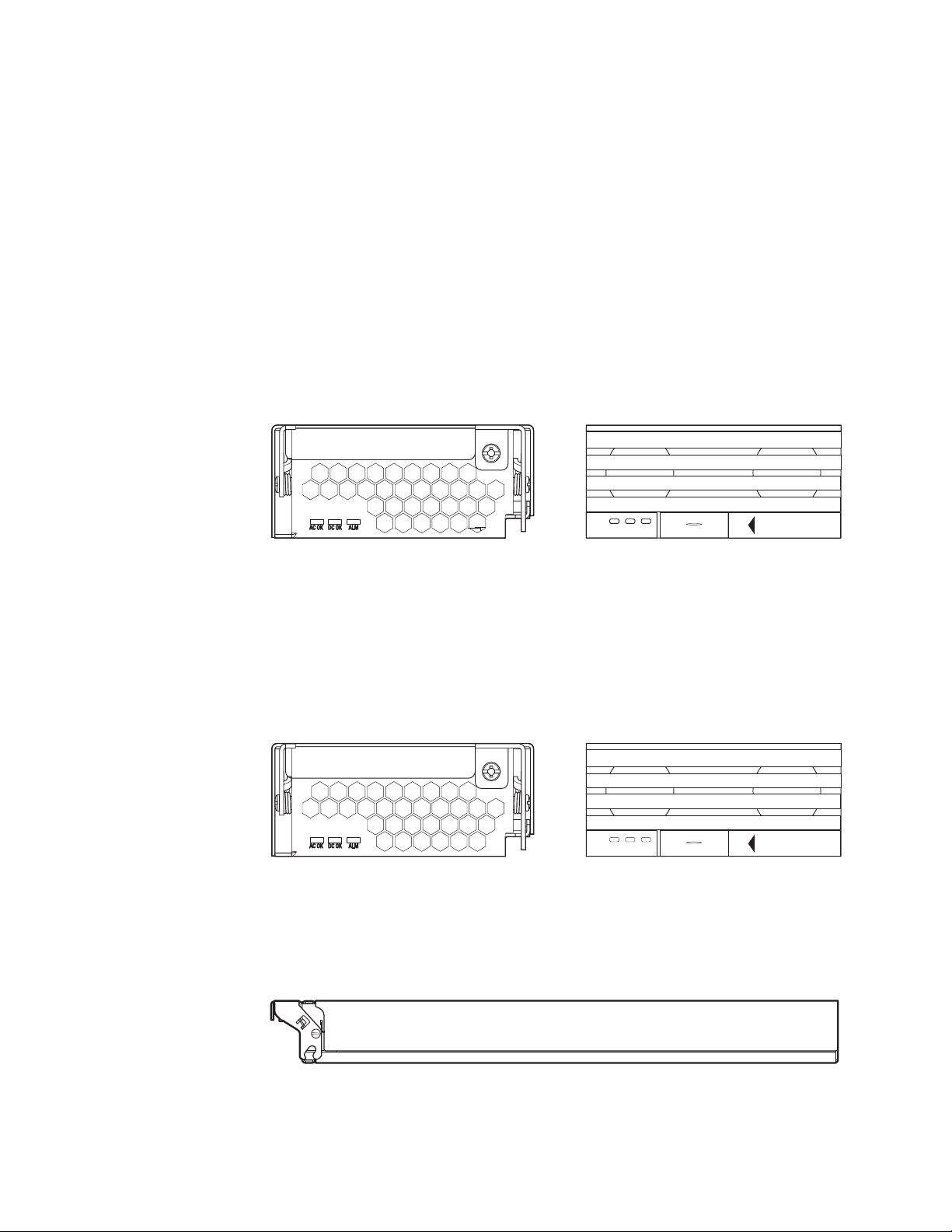
About replacement power supplies
Replacement power supplies for the 90-240 VAC SYS and 90-240 VAC POE, are
functionally equivalent to the original power supplies, and can be used in
combination with the original power supplies in the same chassis. Although the
model numbers for both the newer and older versions of the power supplies are
identical, the front of the power supplies are visually different and the manufacturing
part numbers are different.
The following illustration shows a side-by-side comparison of the 90-240 VAC SYS
replacement power supply and the original power supply. The one on the left is the
replacement power supply and the one on the right is the original power supply.
Figure 13 shows a side-by-side comparison of 90-240 VAC SYS power supplies.
Replacement Power Supply
Original Power Supply
SYS
DC OK ALMAC OK
SX- ACPWR-SYS (part number 32014-xxx)
SX- ACPWR-SYS (part number 30351-xxx)
Figure 13. Comparison of 90-240 VAC SYS power supplies
SYSEJECT
Figure 14 shows a side-by-side comparison of the 90-240 VAC POE replacement
power supply and the original power supply. The one on the left is the replacement
power supply and the one on the right is the original power supply.
Replacement Power Supply
Original Power Supply
POE
DC OK ALMAC OK
POEEJECT
net08bs024
SX-ACPWR-POE (part number 32016-xxx)
SX-ACPWR-POE (part number 30352-xxx)
Figure 14. Side-by-Side Comparison of 90-240 VAC POE power supplies
Figure 15 shows a side view of the replacement power supplies.
Figure 15. Replacement power supplies.
Chapter 2. Product Overview 21
net08bs025
net08bs026
Page 48

The latching mechanism on the front of the replacement power supplies differ from
the latching mechanism on the original power supplies. The latching mechanism
protrudes slightly in front, making the power supplies slightly longer in depth. For
the actual dimensions, see “Physical dimensions and weight of power supplies” on
page 129.
Although the model numbers 90-240 VAC SYS for the replacement and original
power supplies are identical, the manufacturing part numbers are different, as noted
in Table 11 on page 18. The manufacturing part numbers are inscribed on the labels
affixed to the top of the power supplies. As well, the manufacturing part numbers for
all installed power supplies display in the output of the show chassis command.
See “Displaying chassis status and temperature readings” on page 57.
Hardware specifications for the power supplies are in Chapter 8, “Hardware
specifications,” on page 121.
Power supply LEDs
Each power supply has three LEDs on its faceplate. The LEDs are described in
Table 12.
Table 12. LED status and meanings
LED Desired State Meaning
AC OK ON - Green
DC OUT ON - Green
ALM OFF No alarms present
(steady)
(steady)
The power supply
is receiving AC
power from an AC
power source
The power supply
is supplying DC
output power to the
chassis
and the power
supply is in normal
operating condition.
Abnormal
State Meaning/Action
OFF The power supply is not
receiving power from an AC
power source. You can do
the following:
v Make sure that the
power supply cord is
connected securely to
the wall outlet and the
power supply.
v Make sure that the wall
outlet is rated for
115/120V and 20A. If it is
not, obtain a cable that is
compatibly rated for the
outlet.
v Make sure that the wall
outlet has power.
OFF The power supply is not
supplying DC output power
to the chassis.
If this occurs and the AC
OK is green, then there is a
problem with the power
supply and it must be
replaced.
Amber There is an alarm present
and the power supply is
malfunctioning.
Verify the AC input voltage.
22 Ethernet Switch s-series Installation and User Guide
Page 49

About redundant power supplies and power supply failure
A chassis with redundant power supplies can maintain full operation when one or
more power supplies fail. Power supply failure can be a failure of the supply itself or
the office power grid connected to the power supply.
A chassis can be either1+1redundant orN+1redundant. 1 + 1 redundancy
implies that for every power supply, there is another redundant (backup) power
supply. In other words, half of the supplies in the system can fail, and the system
will still operate normally. N + 1 redundancy implies that there is one redundant
power supply for N power supplies, where N is a number greater than one. for
example,3+1redundancy means that in a system with four power supplies, the
system will continue to operate normally if one power supply fails, but will not
operate if more than one power supplies fail.
Power consumption is equally distributed (within a certain percentage depending on
power load or power supply type) among all power supplies in the system. When a
power supply fails, the power load is redistributed equally among the remaining
power supplies. Note that power consumption between POE and System power
supplies is not shared, meaning loss of a System power supply does not impact a
POE power supply, and vice versa.
What happens when one or more system power supplies fail
If one or more System power supplies fail and the system is left with less than the
minimum number of power supplies required for normal operation, the power
supplies will go into overload and the system will start to shut down. Several things
can happen. The output voltage of the remaining good power supplies will likely
drop as they try unsuccessfully to generate more power than they are capable of.
The system will react to a drop in voltage by increasing the current draw. The
hardware will shut down due to over-current protection or under-voltage protection,
whichever takes place first. One by one, the interface modules shut down until the
power is within the power budget of the remaining power supplies. There is no
particular order in which the interface modules will shut down, as this will occur in
hardware and not in software. The management CPU requires power as well, and
may also shut down during a power supply failure.
After a power loss, if the system is left with less than the minimum number of power
supplies required for normal operation, the system will be left in an unknown state.
At this point, manual recovery is required (restore power and power-cycle the
chassis).
What happens when one or more POE power supplies fail
If one or more POE power supplies fail and the system is left with less than the
minimum number of POE power supplies, the POE power supplies will go into
overload. Non-POE functions will not be impacted, provided the System power
supplies are still up and running. Several things can happen with a POE power
supply failure. The output voltage of the remaining good power supplies will likely
drop as they try unsuccessfully to generate more power than they are capable of.
The system will react to a drop in voltage by increasing the current draw. The
hardware will shut down POE function due to over-current protection or
under-voltage protection, whichever occurs first. The interface modules will start to
shut down its POE ports one by one until the over-power is within the power budget
of the remaining power supplies. There is no particular order in which the POE
ports will shut down, as this occurs in hardware and not in software.
Chapter 2. Product Overview 23
Page 50

Cooling system
After a power loss, if the system is left with less than the minimum number of power
supplies required for normal operation, the system will be left in an unknown state.
At this point, manual recovery is required (restore power and power-cycle the
chassis).
The cooling system is contained within the system’s fan tray assembly and
modules. The following components comprise the cooling system:
v The B08S each has six fans.
v The fans operate at four speeds.
v The B16S has two five-speed fans in the rear of the chassis.
v One fan control module. The fan control module maintains the power to the fans,
and controls the fan speed and the reporting of the fan status to the
management module.
v Two temperature sensors on each management module, and one temperature
sensor on each interface module
v One temperature sensor on each switch fabric module (B08S and B16S only).
The fan tray in the B08S is located in the right side of each chassis. The B16S has
two fan trays which are located in the top rear of the chassis.
Upon system startup, the fans operate at low speed, then adjust their speed based
on the current temperature of the modules and the configured temperature
thresholds, or by the manually configured fan speed.
By default, the system polls the temperature sensor on each module every 60
seconds to get a temperature reading. To read additional information about
changing the default temperature polling interval, see “Changing the temperature
polling interval” on page 68. Depending on the temperature readings for the
modules, the system can do the following:
v Leave the fan speed at its current setting.
v Increase the fan speed.
v Decrease the fan speed.
v If the chassis exceeds the highest temperature threshold or shutdown
temperature for five minutes, the system will shut down the device to prevent
damage
If the temperature of a module exceeds specified high temperature thresholds, the
system generates a Syslog message. The system can also power down the chassis
if the temperature exceeds the highest threshold.
You can change default low and high temperature thresholds for modules and fan
speeds. For more information, see “Changing temperature thresholds for thermal
planes and fan speeds on the on the B16S” on page 62.
The chassis ships with all fan components fully installed in the fan tray. To read
additional information about replacing the fan tray, see one of the following sections:
v “Replacing the B08S fan tray” on page 116
v “Replacing the B16S fan assemblies” on page 117
24 Ethernet Switch s-series Installation and User Guide
Page 51

Built-in mounting brackets
The front of each B08S has built-in, fixed mounting brackets that enable you to
front-mount the chassis in a standard 19-inch (EIA310-D) rack. for instructions
about using the adjustable mounting brackets to mount the device in a rack, see
“Installing a chassis in a rack” on page 30.
Alternatively, you can use a rack mount kit (ordered separately) to center-mount the
B08S using two L-shaped mounting brackets. The rack mount kit comes with
instructions for installing the mounting brackets and mounting the device in a rack.
The B16S has adjustable mounting brackets. Two brackets ship with the B16S that
enable you to front-mount or center-mount the chassis in a rack.
Layer 3 routing protocol table sizes
Use the show default values command to display Layer 3 routing protocol table
sizes. The command output shows the default, maximum, and currently configured
values. See the Configuration Guide for an example output.
Chapter 2. Product Overview 25
Page 52

26 Ethernet Switch s-series Installation and User Guide
Page 53

Chapter 3. Installing the Chassis
This chapter describes hardware installation tasks for the devices. Before starting
the installation, see; “Safety notices” on page xiii.
CAUTION:
Servicing of this product or unit is to be performed by trained service
personnel only. (C032)
Note: Information about configuring IP addresses and connecting a chassis to
other network devices are covered in Chapter 4, “Connecting Network
Devices and Checking Connectivity,” on page 45.
Summary of installation tasks
Table 13. Installation tasks for your switch and locations of more detailed information
Task
Number Task Where to Find More Information
1 Unpack the chassis, and verify that all
contents are present.
2 Review the installation cautions and
warnings.
3 Ensure that the physical environment
that will host the chassis has proper
cabling and ventilation.
4 The B08S ships with extra screws
installed in the right side of the
chassis. These screws secure the fan
tray assembly, protecting it from
damage during shipment. You must
remove these screws before installing
the chassis.
5 Install the chassis in a rack.
“Unpacking a system” on page 28
“Installation precautions” on page 28
“Preparing the installation site” on page
29
“Removing extra shipment screws (B08S
only)” on page 29
“Installing a chassis in a rack” on page 30
Because of the weight of a fully
loaded chassis (97 lbs minimum), IBM
recommends mounting a chassis in a
rack before installing the modules and
power supplies.
6 The chassis ships with a slot panel
installed in all module slots that don’t
currently have a module installed. If
you plan to install a module in a slot,
you must remove the slot panel.
If you do not install a module in a slot,
you must keep the slot panel in place.
If you run the chassis with an
uncovered slot, the system will
overheat.
7 Install the management module and
interface modules in the chassis
© Copyright IBM Corp. 2009 27
“Removing the slot panels” on page 32
“Installing the management and interface
modules” on page 33
Page 54

Table 13. Installation tasks for your switch and locations of more detailed
information (continued)
Task
Number Task Where to Find More Information
8 Attach a management station to the
9 Power on the AC power supplies. “Powering on the system” on page 38
10 After the chassis is powered on,
Unpacking a system
Review the list below and verify the contents. If any items are missing, contact the
place of purchase.
v B08S or B16S with the following installed:
– one or two 12-volt System (SYS) power supplies
– fan tray assembly or assemblies
– slot panels installed in all unoccupied slots
– The B08S and B16S also come with two switch fabric modules already
installed.
v Rack Mount Kit (B16S models only)
v Management module(s) (packaged separately)
v Optional interface modules (packaged separately)
v CD-ROM containing software images and the user documentation (including this
guide)
v A 115V AC power cable for each AC power supply
management module’s serial
(console) port or a 10/100/1000
Ethernet port.
observe the LEDs or display the
status of the modules using the CLI to
determine that the chassis is
operating properly.
“Attaching a management station” on
page 37
“Verifying proper operation” on page 40
Installation precautions
Follow these precautions when installing the chassis.
General precautions
Attention: Refer to the “Safety notices” on page xiii before beginning any of these
procedures.
Attention: Do not install the device in an environment where the operating
ambient temperature might exceed 40° C (104° F).
Attention: Make sure the air flow around the front, sides, and back of the device
is not restricted.
Attention: If you do not install a module in a slot, you must keep the slot panel in
place. If you run the chassis with an uncovered slot, the system will overheat.
Attention: Never leave tools inside the chassis.
28 Ethernet Switch s-series Installation and User Guide
Page 55

Power precautions and warnings
CAUTION:
The power supplies are ″hot swappable″, which means they can be removed
and replaced while the chassis is powered on and running. However, IBM
recommends that you disconnect the power supply from the wall outlet
before removing and replacing the supply. The device can be running while a
power supply is being installed or removed, but the power supply itself
should not be connected to a power source. Otherwise, you could be injured
or the power supply or other parts of the device could be damaged.
Attention: Use a separate branch circuit for each AC power cord, which provides
redundancy in case one of the circuits fails.
Attention: The POE power supply is designed exclusively for use with the
X-Series POE devices. The power supply produces extensive power to support
802.3af applications. Installing the power supply in a device other than the X-Series
POE will cause extensive damage to your equipment. Use a separate branch circuit
for each AC power cord, which provides redundancy in case one of the circuits fails.
Attention: Make sure the power supply is properly inserted in the slot. Never
insert the power supply upside down.
Attention: Do not attempt to install the power supply without first opening the
latch on the front of the power supply. Attempting to install the power supply with a
closed latch will result in mechanical damage to the power supply and power supply
slot.
Preparing the installation site
Cabling infrastructure
Note: Ensure that the proper cabling is installed in the site. for information on
cabling, see the following sections in this guide:
v “Attaching a management station” on page 37
v Chapter 4, “Connecting Network Devices and Checking Connectivity,” on page 45
v “Cable specifications” on page 127.
Installation location
Before installing the device, plan its location and orientation relative to other devices
and equipment. Allow at least 7.6 cm (3 in.) of space at the front of the device for
the fiber-optic and power cabling. Also, allow a minimum of 7.6 cm (3 in.) of space
between the sides and the back of the device and walls or other obstructions.
Removing extra shipment screws (B08S only)
The B08S ship with two extra screws installed in the right side of the chassis.
These screws secure the fan tray, protecting it from damage during shipment. You
must remove these screws before installing the chassis. Figure 16 on page 30
shows the location of the screws.
To perform this task, you need a #2 Phillips-head screwdriver.
Chapter 3. Installing the Chassis 29
Page 56

Chassis front
Shipping
screws
Figure 16. Removing the extra screws used for shipment
Installing a chassis in a rack
Because of the weight of a fully loaded chassis (97 lbs minimum), IBM recommends
mounting a chassis in a rack before installing the modules and power supplies.
You can flush mount the B08S using the built-in mounting brackets on the front of
the device. Alternatively, you can use the optional rack mount kit to mid-mount the
chassis in a rack. The B16S does not have adjustable mounting brackets. To mount
the B16S in a rack, you will need to install the brackets in the rack mount kit that
ships with the chassis, as shown in Figure 19 on page 32.
Chassis rear
net08bs027
Before performing this task, you should have an assembled rack and a #2
Phillips-head screwdriver.
See “Rack safety” on page xx for precautions when installing equipment in a rack.
Each device that you install in a rack, you must provide four mounting screws with
which to secure the chassis.
To mount the chassis in a rack using the adjustable mounting brackets, do the
following:
1. Determine the position of each chassis in the rack.
2. Position two of the four mounting screws for each chassis that you plan to
mount in the rack according to the spacings of the keyhole slots on the brackets
as shown in Figure 17 on page 31. Do not secure the screws completely; leave
approximately 1/4 inch of clearance between the back of the screw head and
the rack.
30 Ethernet Switch s-series Installation and User Guide
Page 57

Select holes in rack that match the
keyholes in mounting brackets
(in this case, the top for the
left-hand bracket and the bottom
for the right-hand bracket)
net08bs028
Figure 17. Positioning two of four mounting screws in a rack.
3. Mount the chassis that goes in the lowest position in the rack, as shown in
Figure 18. With two or more people lifting the chassis, slip the wide portion of
each keyhole slot over the corresponding screw in the rack.
net08bs029
Figure 18. Front-mount-rack-installation into chassis
4. Slide the chassis down so that the screw heads are in the narrow portion of the
keyhole slots.
5. Install the remaining two mounting screws through the opposite corners of the
brackets into the rack.
6. Tighten all screws to secure the chassis in place.
7. Repeat the steps to mount each subsequent chassis in the same rack.
Chapter 3. Installing the Chassis 31
Page 58

Installing mounting brackets on the B16S
The B16S does not ship with mounting brackets installed. You will need to install
the brackets yourself, using a #2 Phillips or flathead screwdriver. Mount the
brackets as shown in Figure 19. Since the brackets are identical, you must flip one
bracket 180 degrees to fit on the opposite side from the first bracket.
Empty chassis with slot panels in place
Figure 19. Installing the mounting brackets on an B16S
Consult “Installing a chassis in a rack” on page 30 for instructions on how to install
the B16S in the rack.
Removing the slot panels
The chassis ships with a slot panel installed that covers each empty module slot,
ensuring proper airflow within the chassis. If you plan to install a module in a
particular slot, you must first remove the slot panel.
Attention: If you do not install a module in a slot, you must keep the slot panel in
place. If you operate the chassis with an uncovered slot, the system will overheat.
Although the slot panels may differ in size, the procedure for removing them from
the chassis is the same. The procedure in this section applies to all module slot
panels.
You need a #2 Phillips-head or flathead screwdriver to perform this task.
To remove a slot panel, do the following:
1. Loosen the screws on either end of the slot panel with a #2 Phillips-head or
flathead screwdriver.
2. Pull the slot panel out of the chassis, and store it in a safe place for future use.
net08bs030
32 Ethernet Switch s-series Installation and User Guide
Page 59

Installing the management and interface modules
This section provides the procedures for installing the management and interface
modules. Although the modules may differ in size and function, the procedure for
installing each of them into the chassis is the same. The procedure described in
this section applies to all devices.
The B08S and B16S management modules are hot swappable, which means you
can remove and insert them while the chassis is powered on and running.
Notes:
1. The interface modules are interchangeable among the s-series products.
However, if you try to install them in chassis other than those documented here,
the chassis and interface modules will not function properly.
2. You cannot mix IPv4 and IPv6 modules together in the same chassis. A chassis
must either contain all IPv4 management modules and IPv4 interface modules
or all IPv6 management modules and IPv6 interface modules.
Table 14 provides the chassis slot numbers into which you must install the modules.
The following figures show the chassis with slot numbers:
v B08S - Figure 2 on page 7.
v B16S - Figure 4 on page 9.
Table 14. Module Installation
Module B08S Slot Number B16S Slot Number
Management module 9 and 10 9 and 10
Interface modules 1 - 8 1-8and11-18
Attention: If you do not install a module in a slot, you must leave the slot panel
installed in the slot. If you operate the chassis with an uncovered empty slot, the
system will overheat.
Before installing a module in the chassis, have the following on hand:
v An ESD wrist strap with a plug for connection to the ESD connector on the
chassis.
CAUTION:
For safety reasons, the ESD wrist strap should contain a series 1 meg ohm
resistor.
v A #2 Phillips-head or flathead screwdriver.
To install a module in the chassis, do the following:
1. Put on the ESD wrist strap and ground yourself by inserting the plug into the
ESD connector located on the chassis front.
2. Remove the module from its packaging.
3. Insert the management module or the interface module into the appropriate
chassis slot and slide the card along the card guide until the ejectors on either
side of the module move close to the module front panel.
4. Push the ejectors toward the center of the module to fully seat the module in
the backplane.
5. Use the #2 Phillips-head or flathead screwdriver to tighten the two screws at
either end of the module front panel.
Chapter 3. Installing the Chassis 33
Page 60
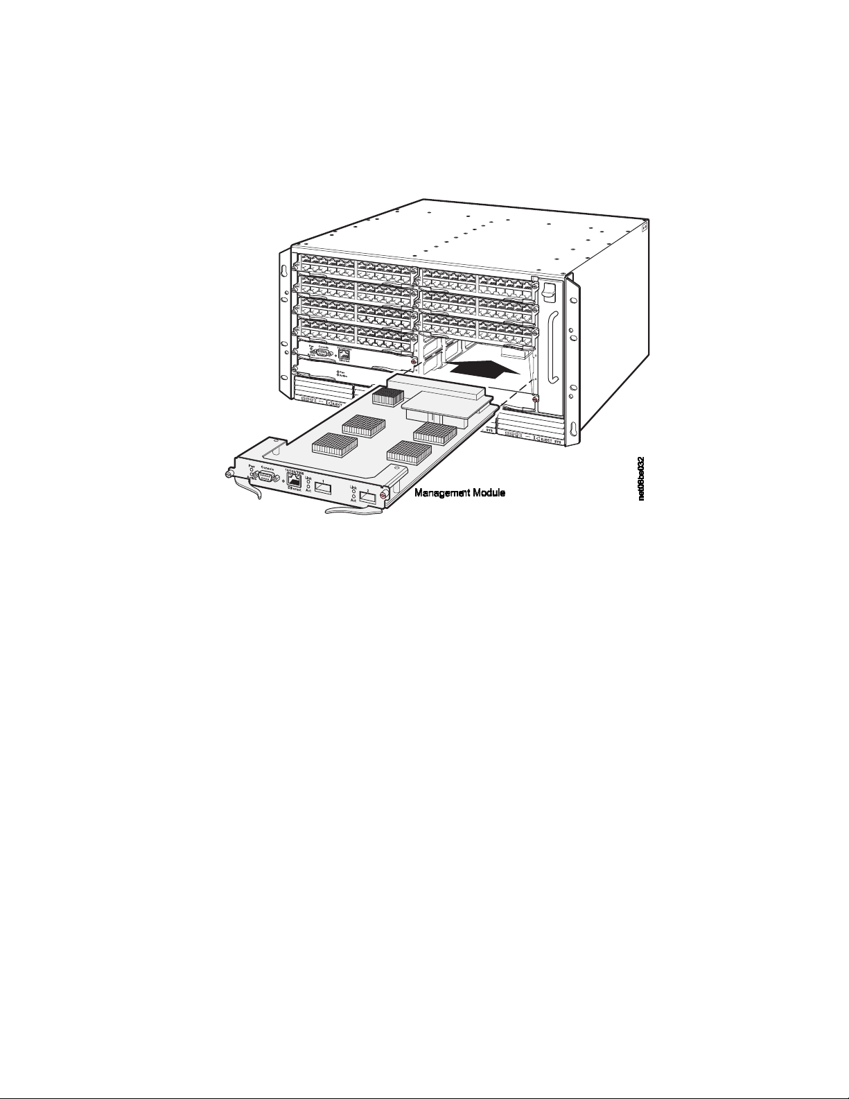
The following illustrations show placement of the management and interface
modules in the devices.
Figure 20 shows the installation of a management module in the B08S.
Figure 20. Installing a management module in the B08S
Figure 21 on page 35 shows the installation of a management module in the B16S.
34 Ethernet Switch s-series Installation and User Guide
Page 61
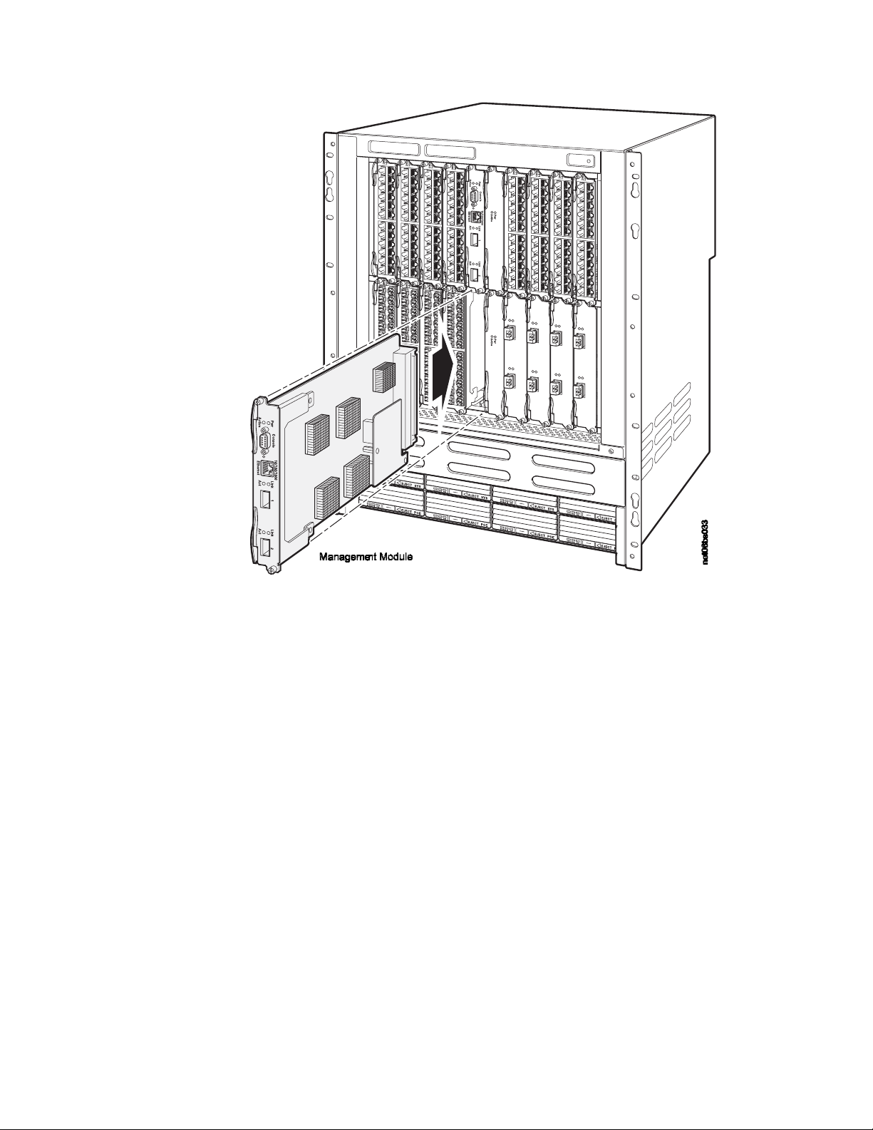
Figure 21. Installing a management module in the B16S chassis
Figure 22 on page 36 shows the installation of an interface module in the B08S
Chapter 3. Installing the Chassis 35
Page 62

Figure 22. Installing an interface module in the B08S
Figure 23 shows the installation of an interface module in the B16S
Figure 23. Installing an interface module in the B16S
36 Ethernet Switch s-series Installation and User Guide
Page 63

Attaching a management station
You can manage the device in the following ways:
v You can connect a PC or terminal to the management module’s serial (console)
port or 10/100/1000 Ethernet port and access the system directly from the PC or
terminal, or from a Telnet connection to the PC or terminal. For more information,
see “Attaching a PC or terminal to the console port or 10/100/1000 copper port.”
v You can connect the switch to your existing management network and manage
the switch, along with other network devices, from a management station. To do
this, you can connect a switch to a Gigabit Ethernet port on the management
module. For more information, see “Attaching a switch to an Ethernet port” on
page 38.
Note: The management network into which you can connect a Gigabit Ethernet
port must be separate and isolated from the network over which user
packets are switched and routed.
Attaching a PC or terminal to the console port or 10/100/1000 copper port
The management module’s console port, which has a male DB-9 serial connector,
and 10/100/1000 Ethernet copper port(s), which have RJ-45 UTP connectors, allow
you to attach a PC or terminal. From the console port, you can access the system’s
CLI directly from the PC or terminal or via a Telnet connection to the PC or
terminal. From the Ethernet port, you can access the system’s CLI or Web
management interface directly from the PC or terminal or via a Telnet connection to
the PC or terminal.
Before performing this task, you need the following items:
v PC running a terminal emulation application or a terminal
v If connecting the PC or terminal to the console port, a straight-through EIA/TIA
DB-9 serial cable with one end terminated in a female DB-9 connector and the
other end terminated in a male or female DB-9 or DB-25 connector, depending
on the specifications of your PC or terminal. You can order the serial cable
separately from IBM or build your own cable. If you prefer to build your own, see
the pinout information in “Serial (console) port pinouts” on page 125.
v If connecting the PC or terminal to a Gigabit Ethernet copper port, a category 5
UTP crossover cable, which you must supply. To read additional information
about the port pin assignments, see “10/100 and Gigabit port pinouts” on page
126.
To attach a PC or terminal to the console port or Gigabit Ethernet copper port, do
the following:
1. Connect a PC or terminal to the console port or a 10/100/1000 Ethernet port
using the appropriate cable.
2. Open the terminal emulation program, and set the session parameters as
follows:
v Baud: 9600 bps
v Data bits: 8
v Parity: None
v Stop bits: 1
Chapter 3. Installing the Chassis 37
Page 64

v Flow control: None
Attaching a switch to an Ethernet port
The B08S and B16S management module’s 10/100/1000 Ethernet copper port
enable you to attach a networking switch. A management station in your existing
management network can then access the switch using the IronView Network
Manager.
For more information, see Chapter 4, “Connecting Network Devices and Checking
Connectivity,” on page 45.
Powering on the system
After you complete the hardware installation, you can power on the system. Verify
that all modules and power supplies are fully and properly installed and no module
slots are uncovered.
Note the following before powering on the system:
Attention: If you do not install a module in a slot, you must keep the slot panel in
place. If you run the chassis with an uncovered slot, the system will overheat.
Note: The wall outlet should be installed near the equipment and should be easily
accessible.
Note: The switch is designed to provide uninterrupted service even when you
insert or remove the interface modules. Therefore, the system does not have
a separate on/off power switch. To turn the system off, unplug the power
cord(s).
Connecting AC power to the chassis
AC power is supplied though an AC power cord that is installed at the rear of the
chassis.
1. At the rear of the chassis, locate the power receptacle where the power
supplies have been installed.
2. Lift the cord-retainer and connect the AC power cord to the power supply.
3. Snap the cord-retainer over the power plug to hold it in place, as illustrated
below.
38 Ethernet Switch s-series Installation and User Guide
Page 65

Figure 24. Connecting AC power to a B08S
Chapter 3. Installing the Chassis 39
Page 66

Figure 25. Connecting AC power cords to a B16S chassis
4. Connect the power cord to the wall outlet.
5. Observe the LEDs on the power supply front panel. The AC OK LEDs should be
green (steady), which indicates the power supply is providing power to the
chassis components. If it is amber or OFF, the power supply is not providing
power to the chassis components. The ALM LED should be OFF.
Verifying proper operation
To verify the proper operation of the chassis after power on, you can do the
following:
v Observe the LEDs
v Display the status of the modules using the CLI
Observing the LEDs
After the chassis powers on, you can observe its LEDs to verify that it initialized
successfully. If a problem persists after taking action described in this table, contact
IBM Support.
40 Ethernet Switch s-series Installation and User Guide
Page 67

Table 15. Desired and possible abnormal LED states after system power-on
Abnormal
LED Desired State Meaning
State Meaning/Action
Management module
Active On The module is functioning
Off Neither of the management
as the active
management module.
Pwr On The module is receiving
Off The module is not receiving power.
power.
10/100/1000 Ethernet
Port
On - Green A link is established with
the remote port.
Off A link is not established with the
module(s) is managing the switch
fabric and interface modules.
A problem could have occurred
during initialization. Check your
attached PC or terminal for possible
error messages.
You can do the following:
Make certain that the module is
installed properly. For more
information, see Installing the
Management and Interface Modules .
See the entry for the AC power
supply LED in this table For more
information.
remote port. You can do the
following:
10/100/1000 Ethernet
Port
On or blinking
- Yellow
The port is transmitting
and receiving packets.
Interface Module
Link/Activity On, or blinking A link is established with
the remote port and the
port is transmitting and
receiving user packets.
POE (if applicable) On - Green The port is enabled, a
power-consuming device
has been detected, and
the module is supplying
power to the device.
Verify that the connection to the
other device has been properly
made. Also, make certain that the
other device is powered on and
operating correctly.
Try using a different cable.
Off for an
extended
The port is not transmitting or
receiving packets.
period
You can check the other 10/100/1000
Ethernet port LED to make sure a
link is established with the remote
port. If not, take the actions
described in the Meaning/Action
column for the other 10/100/1000
Ethernet port LED.
Off At this stage of the installation, you
have not yet cabled the Gigabit
Ethernet ports, so this LED will be
off.
After cabling this port, if this LED is
off, a link is not established with the
remote port.
Off The port is not providing in-line
power.
Chapter 3. Installing the Chassis 41
Page 68

Table 15. Desired and possible abnormal LED states after system power-on (continued)
Abnormal
LED Desired State Meaning
AC Power Supplies
AC OK ON - Green
(steady)
DC OUT ON - Green
(steady)
ALM OFF No alarms present and
The power supply is
receiving AC power from
an AC power source.
The power supply is
supplying DC output
power to the chassis.
the power supply is in
normal operating
condition.
State Meaning/Action
OFF The power supply is not receiving
power from an AC power source.
You can do the following:
Make sure that the power supply
cord is connected securely to the
wall outlet and the power supply.
Make sure that the wall outlet is
rated for 115/120V and 20A. If it is
not, obtain a cable that is compatibly
rated for the outlet.
Make sure that the wall outlet has
power.
OFF The power supply is not supplying
DC output power to the chassis.
If this occurs and the AC OK LED is
Green, then there is a problem with
the power supply and it must be
replaced.
Amber There is an alarm present and the
power supply is malfunctioning.
Verify the AC input and DC output
voltages.
Displaying the module status
After you have attached a PC or terminal to the management module’s console port
or Ethernet port and the IBM device has initialized successfully, press Enter to
display the following CLI prompt in the terminal emulation window:
FastIron>
If you do not see this prompt:
1. Make sure the cable is securely connected to your PC or terminal and the
console port or Ethernet port.
2. Check the settings in your terminal emulation program. In addition to the
session settings listed in “Attaching a PC or terminal to the console port or
10/100/1000 copper port” on page 37, make sure the terminal emulation session
is running on the same serial port you attached to the console port.
If you see the prompt FastIron> or similar, you are connected to the system and
can display the status of the modules using the CLI. Enter the show module
command at any CLI level.
The following shows the output of the show module command when entered on
the B08S. The display output is similar on the B16S.
FastIron SX 800 Switch# show module
Module Status Ports Starting MAC
F1: SX-FISF Switch Fabric active
42 Ethernet Switch s-series Installation and User Guide
Page 69

F2: SX-FISF Switch Fabric active
S1: SX-F424C 24-port Gig Copper OK 24 00e0.beef.0000
S2: SX-F424C 24-port Gig Copper OK 24 00e0.beef.0000
S3: SX-F42XGW 2-port 10G LAN/WAN OK 2 00e0.beef.0030
S4: SX-F424C 24-port Gig Copper OK 24 00e0.beef.0048
S5: SX-F42XGW 2-port 10G LAN/WAN OK 2 00e0.beef.0060
S6: SX-F424C 24-port Gig Copper OK 24 00e0.beef.0078
S7: SX-F424C 24-port Gig Copper OK 24 00e0.beef.0090
S8: SX-F424F 24-port Gig Fiber OK 24 00e0.beef.00a8
S9: SX-FIZMR4 0-port Management Active 0
{ Status : OK }
S10: SX-FIZMR4 0-port Management Standby 0
{ Status : Absent }
Syntax: show module
The Status column shows the module status. The status can be one of the
following:
v OK - The module is up and running
v ACTIVE - This applies to the B08S and B16S management and switch fabric
modules only. This indicates that the module is the active module as opposed to
the standby module.
v STANDBY - This applies to the B08S and B16S management and switch fabric
modules only. This indicates that the module is the standby module as opposed
to the active module.
v FAILED - The management module was unable to bring up an interface module
properly. If you observe this status, make certain that the interface module is
installed properly. For more information, see “Installing the management and
interface modules” on page 33.
v DISABLED - The module is not up and running
Chapter 3. Installing the Chassis 43
Page 70

44 Ethernet Switch s-series Installation and User Guide
Page 71

Chapter 4. Connecting Network Devices and Checking Connectivity
This chapter provides the details for connecting network devices, checking network
connectivity, and troubleshooting any issues that might occur in the process.
Attention: The procedures in this manual are for qualified service personnel.
Table 16. Connecting network devices
Step Task Topic for reference
1 Secure access to the CLI by assigning passwords. “Assigning permanent passwords”
2 Configure IP addresses for the management,
Ethernet, virtual, and loopback interfaces.
3 Connect your device to another networking device. “Connecting network devices” on page 50
4 Test a port for connectivity to other networking
devices using the ping and traceroute commands.
5 Troubleshoot any problems that can arise. “Troubleshooting network connections” on
Assigning permanent passwords
By default, the CLI is not protected by passwords. To secure CLI access, IBM
strongly recommends assigning passwords.
“Configuring IP addresses” on page 46
“Testing network connectivity” on page 54
page 56
Note: You cannot assign a password using the Web management interface. You
can assign passwords using IronView Network Manager if an enable
password for a Super User has been configured on the device.
The CLI contains the following access levels:
v User EXEC - The level you enter when you first start a CLI session. At this level,
you can view some system information but you cannot configure system or port
parameters.
v Privileged EXEC - This level is also called the Enable level and can be secured
by a password. You can perform tasks such as manage files on the flash module,
save the system configuration to flash, and clear caches at this level.
v CONFIG - The configuration level. This level lets you configure the system’s IP
address and configure switching and routing features. To access the CONFIG
mode, you must already be logged into the Privileged level of the EXEC mode.
You can set the following levels of Enable passwords:
v Super User - Allows complete read-and-write access to the system. This is
generally for system administrators and is the only password level that allows
you to configure passwords.
Note: You must set a Super User password before you can set other types of
passwords.
v Port Configuration - Allows read-and-write access for specific ports but not for
global (system-wide) parameters.
v Read Only - Allows access to the Privileged EXEC mode and CONFIG mode but
only with read access.
© Copyright IBM Corp. 2009 45
Page 72

To set passwords:
1. At the opening CLI prompt, enter the following command to change to the
Privileged level of the EXEC mode:
FastIron> enable
2. Access the CONFIG level of the CLI by entering the following command:
FastIron# configure terminal
(config)#
3. Enter the following command to set the super-user password:
FastIron(config)# enable super-user-password <text>
4. Enter the following commands to set the port configuration and read-only
passwords:
FastIron(config)# enable port-config-password <text>
FastIron(config)# enable read-only-password <text>
Syntax: enable super-user-password | read-only-password | port-config-password
<text>
Passwords can be up to 32 characters long.
Configuring IP addresses
You must configure at least one IP address using the serial connection to the CLI
before you can manage the system using the other management interfaces. In
addition, IBM Ethernet routers require an IP subnet address for the subnet in which
you plan to place them in your network.
IPv4 devices
IPv4 devices support both classical IP network masks (Class A, B, and C subnet
masks, and so on) and Classless Inter-domain Routing (CIDR) network prefix
masks.
v To enter a classical network mask, enter the mask in IP address format. For
example, enter: 209.157.22.99 255.255.255.0 for an IP address with a Class-C
subnet mask.
v To enter a prefix number for a network mask, enter a forward slash(/)andthe
number of bits in the mask immediately after the IP address. for example, enter
“209.157.22.99/24” for an IP address that has a network mask with 24 significant
(“mask”) bits.
By default, the CLI displays network masks in classical IP address format (example:
255.255.255.0). You can change the display to the prefix format. See the
Configuration Guide For more information.
IPv4 devices running layer 3 software
Before attaching equipment to a router, you must assign an interface IP address to
the subnet on which the router will be located. You must use the serial connection
to assign the first IP address. for subsequent addresses, you also can use the CLI
through Telnet or the Web management interface.
By default, you can configure up to 24 IP interfaces on each port, virtual interface,
and loopback interface. You can increase this amount to up to 64 IP subnet
addresses per port by increasing the size of the subnet-per-interface table. See the
Configuration Guide For more information.
46 Ethernet Switch s-series Installation and User Guide
Page 73

The following procedure shows how to add an IPv4 address and mask to a router
port.
1. At the opening CLI prompt, enter enable.
FastIron> enable
2. Enter the following command at the CLI Privileged EXEC level prompt, then
press Enter. This command erases the factory test configuration if still present:
FastIron# erase startup-config
Attention: Use the erase startup-config command only for new systems. If
you enter this command on a system you have already configured, the
command erases the configuration. If you accidentally do erase the
configuration on a configured system, enter the write memory command to
save the running configuration to the startup-config file.
3. Access the configuration level of the CLI by entering the following command:
Privileged EXEC Level:
FastIron# configure terminal
Global CONFIG Level:
FastIron(config)#
4. Configure the IPv4 address and mask address for the interface:
FastIron(config)# int e 1/5
FastIron(config-if-e1000-1/5)# ip address 192.22.3.44 255.255.255.0
Note: You can use the syntax ip address <ip-addr>/<mask-bits> if you know
the subnet mask length. In the above example, you could enter ip
address 192.22.3.44/24.
Syntax: enable [<password>]
Syntax: configure terminal
Syntax: [no] ip address <ip-addr> <ip-mask> [secondary]
or
Syntax: [no] ip address <ip-addr>/<mask-bits> [secondary]
Use the secondary parameter if you have already configured an IP address
within the same subnet on the interface.
IPv4 devices running layer 2 software
To configure an IPv4 address to a device running Layer 2 software:
1. At the opening CLI prompt, enter enable.
FastIron> enable
2. Enter the following command at the Privileged EXEC level prompt (for example,
FastIron#), then press Enter. This command erases the factory test
configuration if still present:
FastIron# erase startup-config
Attention: Use the erase startup-config command only for new systems. If
you enter this command on a system you have already configured, the
command erases the configuration. If you accidentally do erase the
configuration on a configured system, enter the write memory command to
save the running configuration to the startup-config file.
3. Access the configuration level of the CLI by entering the following command:
Privileged EXEC Level:
FastIron# configure terminal
Chapter 4. Connecting Network Devices and Checking Connectivity 47
Page 74

IPv6 devices
Global CONFIG Level:
FastIron(config)#
4. Configure the IPv4 address and mask for the switch.
FastIron(config)# ip address 192.22.3.44 255.255.255.0
5. Set a default gateway address for the switch.
FastIron(config)# ip default-gateway 192.22.3.1
Note: You do not need to assign a default gateway address for single subnet
networks.
Syntax: enable [<password>]
Syntax: configure terminal
Syntax: [no] ip address <ip-addr> <ip-mask>
or
Syntax: [no] ip address <ip-addr>/<mask-bits>
Syntax: ip default-gateway <ip-addr>
IPv6 devices support the 128-bit addressing format, composed of 8 fields of 16-bit
hexadecimal values separated by colons (:). For example,
2001:0000:0000:0200:002D:D0FF:FE48:4672 is an IPv6 address, which can also be
expressed as 2001:0:0:200:2D:D0FF:FE48:4672 after omitting the leading zeros.
IPv6 devices running Layer 3 software
Before attaching equipment to a router, you must assign an interface IP address to
the subnet on which the router will be located. You must use the serial connection
to assign the first IP address. for subsequent addresses, you also can use the CLI
through Telnet or the Web management interface.
By default, you can configure up to 24 IP interfaces on each port, virtual interface,
and loopback interface. You can increase this amount to up to 64 IP subnet
addresses per port by increasing the size of the subnet-per-interface table. See the
Configuration Guide For more information.
The following procedure shows how to add an IPv6 address and mask to a router
port.
1. At the opening CLI prompt, enter enable.
FastIron> enable
2. Enter the following command at the CLI Privileged EXEC level prompt, then
press Enter. This command erases the factory test configuration if still present:
FastIron# erase startup-config
Attention: Use the erase startup-config command only for new systems. If
you enter this command on a system you have already configured, the
command erases the configuration. If you accidentally do erase the
configuration on a configured system, enter the write memory command to
save the running configuration to the startup-config file.
3. Access the configuration level of the CLI by entering the following command:
Privileged EXEC Level:
FastIron# configure terminal
Global CONFIG Level:
48 Ethernet Switch s-series Installation and User Guide
Page 75

FastIron(config)#
4. Configure the IPv6 address and mask address for the interface:
FastIron(config)# int e 1/5
FastIron(config-if-e1000-1/5)# ipv6 address
2001:200:12D:1300:240:D0FF:FE48:4672:/64
These commands configure the global prefix 2001:200:12d:1300::/64 and the
interface ID ::240:D0FF:FE48:4672, and enable IPv6 on interface e 1/5.
Note: The above procedure shows how to configure an IPv6 address with a
manually configured Interface ID as the address for the interface. You could
also configure an IPv6 address with an automatically computed EUI-64
Interface ID as the address for the interface. Link-local IPv6 addresses are
also supported. For details, see the Configuration Guide.
Syntax: enable [<password>]
Syntax: configure terminal
Syntax: [no] ipv6 address <ipv6-prefix>/<prefix-length>
You must specify the <ipv6-prefix> parameter in hexadecimal using 16-bit values
between colons as documented in RFC 2373.
You must specify the <prefix-length> parameter in decimal value. A slash mark (/)
must follow the <ipv6-prefix> parameter and precede the <prefix-length> parameter.
IPv6 devices running Layer 2 software
To configure an IPv6 address to a device running Layer 2 software:
1. At the opening CLI prompt, enter enable.
FastIron> enable
2. Enter the following command at the Privileged EXEC level prompt (for example,
#), then press Enter. This command erases the factory test configuration if still
present:
FastIron# erase startup-config
Attention: Use the erase startup-config command only for new systems. If
you enter this command on a system you have already configured, the
command erases the configuration. If you accidentally do erase the
configuration on a configured system, enter the write memory command to
save the running configuration to the startup-config file.
3. Access the configuration level of the CLI by entering the following command:
Privileged EXEC Level:
FastIron# configure terminal
Global CONFIG Level:
FastIron(config)#
4. Configure the IP address and mask for the switch.
FastIron(config)# ipv6 address 2001:200:12D:1300:240:D0FF:FE48:4000:1/64
Note: The above procedure shows how to configure an IPv6 address with a
manually configured interface ID as the system-wide address for the switch.
You could also configure an IPv6 address with an automatically computed
Chapter 4. Connecting Network Devices and Checking Connectivity 49
Page 76

EUI-64 interface ID as the system-wide address for the switch. A link-local
IPv6 address is also supported. For details, see the Configuration Guide.
Syntax: enable [<password>]
Syntax: configure terminal
Syntax: [no] ipv6 address <ipv6-prefix>/<prefix-length>
You must specify the <ipv6-prefix> parameter in hexadecimal using 16-bit values
between colons as documented in RFC 2373.
You must specify the <prefix-length> parameter in decimal value. A slash mark (/)
must follow the <ipv6-prefix> parameter and precede the <prefix-length>
parameter.192.22.3.44 255.255.255.0
Connecting network devices
These devices support connections to other vendors’ routers, switches, and hubs,
as well other IBM devices.
Cable specifications
See “Cable specifications” on page 127 for cable lengths and types.
Connecting to Ethernet or fast Ethernet hubs
For copper connections to Ethernet hubs, a 10/100Base-TX or 1000Base-T switch,
or another IBM device, a crossover cable is required. If the hub is equipped with an
uplink port, it will require a straight-through cable instead of a crossover cable.
Note: The 802.3ab standard (automatic MDI/MDIX detection) calls for automatic
negotiation of the connection between two 1000Base-T ports. Therefore, a
crossover cable may not be required; a straight-through cable may work as
well. For more information about this feature, see the Configuration Guide.
Figure 26 on page 51 shows a UTP crossover cable.
50 Ethernet Switch s-series Installation and User Guide
Page 77

Cat-5 crossover cable
1000BaseT
2
1
Figure 26. UTP crossover cable
8
33
4
5
6
7
8
Figure 27 shows a cat-5 crossover cable for 1000Base-T.
Cat-5 Crossover Cable
1000BaseT
11
2
4
5
6
7
8
net48bg028
1
2
1
Figure 27. Cat-5 crossover cable for 1000Base-T
8
3
4
5
6
7
8
Note: The 802.3ab standard calls for automatic negotiation of the connection
between two 1000Base-T ports. Consequently, a crossover cable may not be
required; a straight-through cable may work as well.
Connecting to workstations, servers, or routers
Straight-through UTP cabling is required for direct UTP attachment to workstations,
servers, or routers using network interface cards (NICs).
Fiber cabling with LC connectors is required for direct attachment to Gigabit NICs or
switches and routers.
1
2
3
4
5
6
7
8
net08bs043
Note: The 802.3ab standard (automatic MDI/MDIX detection) calls for automatic
negotiation of the connection between two 1000Base-T ports. Therefore, a
crossover cable may not be required; a straight-through cable may work as
well. For more information about this feature, see the Configuration Guide.
Chapter 4. Connecting Network Devices and Checking Connectivity 51
Page 78

Connecting a network device to a fiber port on the device
For direct attachment from the device to a Gigabit NIC, switch, or router, fiber
cabling with an LC connector is required.
Note: All physical IP interfaces on the Layer 3 devices share the same MAC
address. For this reason, if more than one connection is made between two
devices, one of which is an s-series Layer 3 device, IBM recommends the
use of virtual interfaces. It is not recommended to connect two or more
physical IP interfaces between two routers.
To connect a device to another network device using a fiber port, you must do the
following:
1. Install a fiber optic module (SFP transceiver for Gigabit Ethernet ports, or
XFP-MSA transceiver for 10-Gigabit Ethernet ports)
2. Cable the fiber optic module
The following sections provide information about performing these tasks.
Installing a fiber optic module
You must install a fiber optic module in each Gigabit Ethernet and 10-Gigabit
Ethernet fiber port you want to use.
Attention: Before beginning any of these procedures, read the “Safety notices” on
page xiii.
Before installing a fiber optic module, have the following on hand:
v An ESD wrist strap with a plug for connection to the ESD connector on the
chassis.
CAUTION:
for safety reasons, the ESD wrist strap should contain a series 1 meg ohm
resistor.
To install a fiber optic module into a Gigabit Ethernet or 10-Gigabit Ethernet port, do
the following:
1. Put on the ESD wrist strap and ground yourself by inserting the plug into the
ESD connector located in the lower right corner of the chassis front.
2. Remove the module from its protective packaging.
3. If necessary, remove the metal cover from the port on the interface module’s
control panel.
4. Gently insert the fiber-optic module into the port until the module clicks into
place. The fiber-optic modules are keyed to prevent incorrect insertion.
Cabling a fiber optic module
To cable a fiber-optic module, do the following:
1. Remove the protective covering from the fiber optic module and store the
covering for future use.
2. Before cabling a fiber optic module, IBM strongly recommends cleaning the
cable connectors and the port connectors. For more information, see “Cleaning
fiber optic modules” on page 53.
52 Ethernet Switch s-series Installation and User Guide
Page 79

3. Gently insert the cable connector(s) (a tab on each connector should face
upward) into the port connector(s) until the tabs lock into place.
Cleaning fiber optic modules
To avoid problems with the connection between the fiber optic module (SFP or
XFP) and the fiber cable connectors, IBM strongly recommends cleaning both
connectors each time you disconnect and reconnect them. See “Cleaning the fiber
optic connectors” on page 91.
Automatic MDI/MDIX detection
All 10/100 and Gigabit Ethernet Copper ports on the devices support automatic
Media Dependent Interface (MDI) and Media Dependent Interface Crossover
(MDIX) detection. This feature is enabled on all 10/100 and Gigabit copper ports by
default. For each port, you can disable auto MDI/MDIX, designate the port as an
MDI port, or designate the port as an MDIX port.
For more information about this feature and how configure it, see the Configuration
Guide.
Using a CX4 transceiver
A twin-axial 10G copper CX4 XFP transceiver can be installed in any 10G port. for
a link to operate properly, both sides must use identical CX4 transceivers.
The CX4 transceiver requires a 15 meter CX4-grade cable with 24 or 26 American
Wire Gauge (AWG).
Note: The CX4 transceiver is not hot-swappable.
net48bg053
Figure 28. CX4 transceiver
Chapter 4. Connecting Network Devices and Checking Connectivity 53
Page 80

C 4Transceiver Infiniband cableX
Figure 29. CX4 transceiver cable
Testing network connectivity
After you install the network cables, you can test network connectivity to other
devices by pinging those devices. You also can observe the LEDs related to
network connection and perform trace routes.
Pinging an IP address
To verify that you can reach another device through the network, enter the ping
command at any level of the CLI on the device:
FastIron> ping 192.33.4.7
Syntax: ping
<ip addr> | <hostname> [source <ip addr>] [count <num>] [timeout <msec>] [ttl <num>]
[size <byte>] [quiet] [numeric] [no-fragment] [verify] [data <1-to-4 byte hex>] [brief]
See the Configuration Guide to read additional information about the parameters.
net48bg030
Note: If you address the ping to the IP broadcast address, the device lists the first
four responses to the ping.
Observing LEDs
After you install the network cables, you can observe certain LEDs to determine if
the network connections are functioning properly. Table 17 on page 55 outlines the
LEDs related to the network connections, the desired state of each LED, possible
abnormal states of each LED, and what to do if an LED indicates an abnormal
state.
Note: Some modules use combined link and activity LEDs.
54 Ethernet Switch s-series Installation and User Guide
Page 81

Table 17. Network Connection-Related LED States
LED Desired State Meaning Abnormal State Meaning/Action
Link On (Green) A link is established with
the remote port.
Active On or blinking
(Yellow)
The port is transmitting
and receiving user
packets.
Off A link is not established with the
remote port. You can do the following:
v Verify that the connection to the
other network device has been
properly made. Also, make certain
that the other network device is
powered on and operating correctly.
v Verify that the transmit port on the
device is connected to the receive
port on the other network device,
and that the receive port on the
device is connected to the transmit
port on the other network device. If
you are not certain, remove the two
cable connectors from the port
connector and reinsert them in the
port connector, reversing their order.
v Dust may have accumulated in the
cable connector or port connector.
To read additional information about
cleaning the connectors, see
“Cleaning fiber optic modules” on
page 53.
v If the other actions don’t resolve the
problem, try using a different port or
a different cable.
Off for an
extended period.
The port is not transmitting or receiving
user packets. You can do the following:
v Check the Link LED to make sure
the link is still established with the
remote port. If not, take the actions
described in the Meaning/Action
column for the Link LED.
v Verify that the port has not been
disabled through a configuration
change. You can use the CLI. If you
have configured an IP address on
the device, you also can use the
Web management interface or
IronView Network Manager.
Tracing a route
If a problem persists after taking these actions, contact IBM Support.
To determine the path through which a device can reach another device, enter a
command such as the following at any level of the CLI on the device:
FastIron> traceroute 192.33.4.7
Syntax: traceroute traceroute <host-ip-addr> [maxttl <value>] [minttl
<value>] [numeric] [timeout <value>] [source-ip <ip addr>]
Chapter 4. Connecting Network Devices and Checking Connectivity 55
Page 82

The CLI displays trace route information for each hop as soon as the information is
received. Traceroute requests display all responses to a given TTL. In addition, if
there are multiple equal-cost routes to the destination, the device displays up to
three responses by default.
See the Command Line Interface Reference to read additional information about the
command syntax.
Troubleshooting network connections
To resolve problems that may arise with network connections:
v For the indicated port, verify that both ends of the cabling (at the device and the
connected device) are snug.
v Verify that the IBM device and the connected device are both powered on and
operating correctly.
v Verify that the port has not been disabled through a configuration change. You
can use the CLI. If you have configured an IP address on the device, you also
can use the Web management interface or IronView Network Manager.
v Verify that you have used the correct cable type for the connection:
– for twisted-pair connections to an end node, use straight-through cabling.
– for fiber-optic connections, verify that the transmit port on the device is
connected to the receive port on the connected device, and that the receive
port on device is connected to the transmit port on the connected device.
v For copper ports, you can test the cable using Virtual Cable Testing. For more
information, see the chapter, ″Monitoring Hardware Components″ in the
Configuration Guide.
v If the other procedures don’t resolve the problem, try using a different port or a
different cable.
Digital optical monitoring
You can configure your device to monitor optical transceivers in the system, either
globally or by specified port(s). When this feature is enabled, the system will
monitor the temperature and signal power levels for the optical transceivers in the
specified port(s). Console messages and syslog messages are sent when optical
operating conditions fall below or rise above the XFP or SFP manufacturer’s
recommended thresholds. For details about this feature and how to configure it, see
the Configuration Guide.
56 Ethernet Switch s-series Installation and User Guide
Page 83

Chapter 5. Managing the Chassis and Modules
This chapter contains information about refining the configuration of, monitoring,
and managing the hardware components.
Displaying chassis status and temperature readings
You can display the following information related to the chassis:
v Status of the power supplies
v Status of the fans
v Temperature readings and thresholds of the management and interface modules
v Temperature readings and thresholds of the switch fabric modules.
v The MAC address of the chassis
The following shows an example of the show chassis command output on the
B08S. The display is similar on the running software release 03.0.00 or later.
SX 800 Router#show chassis
Chassis Type: SX 800
Power supply 1 not present
Power supply 2 not present
Power supply 3 (H1250C - AC - Regular) present, status ok
Power supply 4 not present
Fan 1 ok, speed (auto): 1<->