

Page 1

Enterprise Server S80
pSeries 680 Model S85
Service Gui de
SA38-0558-01
No Graphic to be printed on front cover.
Delete this note before printing.
Book trim size is 7 3/8 x 9 inches
Front Cover is 10pt. Carolina stock or equivalent C1S (coated one side)
Note to Printer:
Page 2

Page 3

Enterprise Server S80
pSeries 680 Model S85
Service Gui de
SA38-0558-01
Page 4

Second Edition (November 2000)
Before using this information and the product it supports, read the information in “Safety Notices” on page xiii,
“Appendix A. Environmental Notices” on page 591, and “Appendix B. Notices” on page 593.
© Copyright International Business Machines Corporation 1999, 2000. All rights reserved.
US Government Users Restricted Rights – Use, duplication or disclosure restricted by GSA ADP Schedule Contract
with IBM Corp.
Page 5

Contents
Safety Notices .......................xiii
Rack Safety Instructions.....................xiii
ElectricalSafety.......................xv
Laser Safety Information ....................xvi
Data Integrity and Verification ..................xvii
About This Book ......................xix
ISO 9000 .........................xix
OnlinePublications......................xix
RelatedPublications......................xix
Trademarks .........................xx
Chapter 1. Reference Information .................1
Models S80 and S85 Overview ...................1
Models S80 and S85 Data Flow ..................2
Powering the System On and Off ..................3
Console Strategy .......................3
Power-On Self-Test.......................4
POST Indicators ........................4
POST Keys .........................4
Numerical1Key.......................5
Numerical5Key.......................5
Numerical6Key.......................5
Numerical8Key.......................5
Models S80 and S85 Locations...................6
System and I/O Rack Configurations ................7
Basic Configuration with H50 and H70 Sharing the I/O Rack........10
System with Two I/O Drawers and H50 and H70 Sharing the I/O Rack ....12
System with One I/O Drawer, and Two H50 and H70s Sharing the I/O Rack 14
System Rack Locations ....................16
System Rack Locations Front ..................17
System Rack Locations Rear ..................18
I/O Rack Front Locations ...................19
I/O Rack Rear Locations ...................20
I/O Drawer Locations ......................21
10 EIA-Unit I/O Drawer Front View ................21
10 EIA-Unit I/O Drawer Rear View ................22
10 EIA-Unit I/O Drawer I/O Board Locations .............24
Service Processor Card Locations ................25
Fan Monitor Control (FMC) Card Locations (10 EIA-Unit I/O Drawer) .....26
Power Distribution Board Locations ................26
System Memory .......................27
Memory Locations and Ordering Rules ................27
System Rack Operator Panel ...................29
I/O Drawer Indicator Panel ....................30
10 EIA-Unit I/O Drawer Indicator Panel ...............30
© Copyright IBM Corp. 1999, 2000 iii
Page 6

Cabling the System Rack and I/O Rack ...............31
Connecting JTAG and Operator Panel Cables ............32
Connecting RIO and SPCN Cables ................32
Models S80 and S85 Power Overview ................38
System Rack Power .....................38
I/O Rack Power ......................38
Models S80 and S85 Cabling ...................40
I/O Drawer Cabling .....................41
SCSI IDs and Bay Locations ..................42
Location Codes .......................44
Physical Location Codes ...................44
Location Code Format ....................44
AIX Location Codes .....................45
AIX and Physical Location Code Reference Tables ............48
System Rack .......................48
I/O Drawer 0 Locations ....................53
I/O Drawer 1 Locations ....................57
I/O Drawer 2 Locations ....................60
I/O Drawer 3 Locations ....................63
SCSI Device Locations ....................66
Specifications ........................67
Models S80 and S85 System Rack ................67
NoiseEmissionNotes....................71
External AC Power Cables ....................71
Service Inspection Guide ....................72
Chapter 2. Introduction to Diagnostics ...............73
Maintenance Analysis Procedures (MAPs) ...............73
Error Codes .........................74
Displaying and Using SRCs ..................74
IPL Checkpoints and Error Codes .................75
FRUIsolation........................75
Electronic Service Agent ....................76
Using the Service Processor and Electronic Service Agent ........76
Chapter 3. Maintenance Analysis Procedures (MAPs) ..........79
EntryMAP.........................79
QuickEntryMAP.......................80
Quick Entry MAP Table of Contents ................80
MAP 1020: Problem Determination .................84
Purpose of This MAP.....................84
Step 1020-1 ........................85
Step 1020-2 ........................86
Step 1020-3 ........................87
Step 1020-4 ........................87
MAP 1520: Power .......................88
Cannot Power On System Rack (No Error Code) ...........90
Cannot Power On I/O Rack (No Error Code) .............95
I/O Rack Becomes Powered On, But A Rack-Mounted Unit Does Not Become
Powered On .......................97
iv Service Guide
Page 7

System Rack, I/O Rack, or Rack-Mounted Unit Cannot Be Powered Off . . . 100
The SRC Table Directed You Here and the SRC is 1xxx1200 .......102
The SRC Table Directed You Here and the SRC is 1xxx120y or 1xxx140y 105
Regulator Problem Isolation ..................110
Power Good Problem Isolation .................112
ACBoxProblemIsolation...................114
MAP 1540: Minimum Configuration .................117
Step 1540-1 .......................118
Step 1540-2 .......................118
Step 1540-3 .......................119
Step 1540-4 .......................120
Step 1540-5 .......................120
Step 1540-6 .......................120
Step 1540-7 .......................121
Step 1540-8 .......................121
Step 1540-9 .......................122
Step 1540-10 .......................122
Step 1540-11 .......................123
Step 1540-12 .......................123
Step 1540-13 .......................124
Step 1540-14 .......................124
Step 1540-15 .......................124
Step 1540-16 .......................124
Step 1540-17 .......................125
Step 1540-18 .......................125
Step 1540-19 .......................125
Step 1540-20 .......................126
Step 1540-21 .......................126
Step 1540-22 .......................126
Step 1540-23 .......................128
Step 1540-24 .......................128
Step 1540-25 .......................128
Step 1540-26 .......................128
Step 1540-26a ......................129
Step 1540-27 .......................129
Step 1540-28 .......................129
Step 1540-29 .......................129
Step 1540-30 .......................129
Step 1540-31 .......................129
Step 1540-32 .......................130
Step 1540-33 .......................130
Step 1540-34 .......................130
Step 1540-35 .......................131
Step 1540-36 .......................131
Step 1540-37 .......................131
Step 1540-38 .......................132
Step 1540-39 .......................132
Step 1540-40 .......................133
Chapter 4. Checkpoints ....................135
Contents v
Page 8

IPLFlow .........................135
System Processor Checkpoints .................138
Service Processor Checkpoints .................140
Firmware Checkpoints ....................142
Boot Problems ......................155
Chapter 5. Error Code to FRU Index ...............157
Firmware/POST Error Codes ...................159
Service Processor Error Codes .................175
Unit Reference Codes .....................185
(0000) Operator Panel Reference Codes ..............187
(1xxx) System Power Control Network (SPCN) Reference Codes......189
(A1xx, B1xx) Service processor Reference Codes ...........216
(B006) Common Firmware Reference Codes ............218
Processor Reference Codes ...................220
(B4xx) System Processor Reference Codes .............220
Bus SRN to FRU Reference Table .................440
Chapter 6. Loading the System Diagnostics In Service Mode .......445
Default Boot List and Service Mode Bootlist ..............446
Chapter 7. Service Processor Menus ...............447
Service Processor Menus ....................448
Accessing Service Processor Menus Locally ............448
Accessing the Service Processor Menus Remotely ..........448
Saving and Restoring Service Processor Settings ...........449
Returning to Service Processor Menus ..............449
MenuInactivity......................449
General User Menus .....................450
Privileged User Menus .....................451
MainMenu........................451
Service Processor Setup Menu .................453
Passwords ........................453
System Power Control Menu ..................456
System Information Menu ...................457
Language Selection Menu ..................459
Call-In/Call-Out Setup Menu ..................460
Modem Configuration Menu ..................461
SerialPortSelectionMenu..................462
Serial Port Speed Setup Menu .................462
Telephone Number Setup Menu.................463
Call-OutPolicySetupMenu..................464
Customer Account Setup Menu .................465
Reboot/Restart Policy Setup Menu ................466
Boot Mode Menu .....................467
Service Processor Procedures in Service Mode ............468
Service Processor Functions ...................469
System Power-On Methods ...................470
Service Processor Call-In Security .................471
Service Processor Reboot/Restart Recovery .............471
vi Service Guide
Page 9

Boot (IPL) Speed .....................471
Failure During Boot Process ..................471
Failure During Normal System Operation..............471
Service Processor Reboot/Restart Policy Controls...........472
Configuring and Deconfiguring Processors ..............473
Processor Deconfiguration During Boot ..............473
Service Processor System Monitoring - Surveillance ...........474
System Firmware Surveillance .................474
Operating System Surveillance .................474
Call-Out(Call-Home).....................475
Console Mirroring ......................476
System Configuration ....................476
Service Processor Error Logs ..................476
System POST Errors .....................477
LCDProgressIndicatorLog...................478
Chapter 8. System Management Services..............479
Text-Based System Management Services ..............479
Password Utilities .....................480
DisplayErrorLog .....................481
Remote Initial Program Load Setup ...............482
SCSI Utilities .......................485
Select Console ......................485
Multiboot ........................486
Select Language ......................489
OKPrompt........................489
Exiting System Management Services...............489
Chapter 9. Removal and Replacement Procedures ..........491
Handling Static-Sensitive Devices .................491
Powering Off and Powering On the System ..............492
Powering Off the System ...................492
Powering On the System ...................493
Hot-Swappable FRUs .....................493
System Rack Removal and Replacement Procedures ..........493
Fast Power Up Feature ...................494
Covers .........................494
ACBox.........................495
Hot-Swappable Front Blowers .................495
Hot-Swappable Rear Blowers .................496
ElectronicCards......................496
Operator Panel ......................497
Operator Panel Battery....................498
Operator Panel Cable (Op-panel to SP Cable) ............499
Hot-Swappable Bulk Power Supply................500
Bulk Power Subframe ....................501
Programmable Power Regulators ................502
SPCN Card .......................502
System Backplane Assembly ..................503
Rear Cage ........................505
Contents vii
Page 10

Dual Line Cord .......................505
Removal ........................505
Replacement .......................506
I/O Rack Removal and Replacement Procedures ............507
Front Door ........................507
Installing a 10 EIA-Unit I/O Drawer into an I/O rack ..........507
Install the 10 EIA-Unit I/O Drawer ................510
Service Position ......................512
Operating Position .....................512
10 EIA-Unit I/O Drawer Removal and Replacement Procedures .......513
I/OTray.........................513
Hot-Swappable Blower Assembly ................514
Power Supply Test Switch Procedure ...............515
Hot-Swappable Power Supplies and Power Supply Fan Assemblies .....516
FanMonitorControl(FMC)Card................518
Power Distribution Board Assembly ...............519
Media Devices (CD-ROM Drive, Tape Drive, Diskette Drive) .......520
Hot-Swappable Disk Drives ..................521
SCSI Backplane ......................527
Drawer Indicator Panel Assembly ................529
Service Processor Card ...................530
Adapters ........................532
I/O Planar ........................532
Bulkhead Card ......................533
Chapter 10. Models S80 and S85 Parts...............535
Part-Name to Part-Number Index .................536
System Rack Parts ......................540
Front, Rear, and Top Covers ..................540
Internal Shields (Front and Rear) ................542
Operator Panel, Brackets, and Covers (Front View) ..........544
Operator Panel Assembly ...................546
Bulk Power Supplies and Front Blowers (Front View)..........548
AC Box Assembly and Rear Blowers (Rear View) ...........550
Front Electronics Cage and System Backplane Assembly ........552
Rear Electronics Cage ....................554
ElectronicCards......................556
Power Subframe (Rear View, 1 of 3) ...............558
Power Subframe (Rear View, 2 of 3) ...............560
Power Subframe (3 of 3) ...................562
I/O Drawer Parts .......................564
10 EIA Unit I/O Drawer Parts..................564
10 EIA-Unit I/O Drawer Power Cables...............566
I/O Planar to Bulkhead Cabling 10 EIA-Unit Drawers ..........568
SCSI Signal Cabling 10 EIA-Unit I/O Drawer ............570
I/O Rack Parts .......................572
I/O Rack Covers ......................572
I/O Rack Labels ......................574
Rails and Front Bezels ....................576
Power Distribution Bus ....................578
viii Service Guide
Page 11

Leveling Feet and Bolt Down Hardware ..............580
Accessory Electrical Outlet Mounting Plates .............582
Accessories ........................584
Power Cables .......................584
Keyboards and Mouse ....................586
Keyboards and Mouse (Black) .................588
Appendix A. Environmental Notices................591
Product Recycling and Disposal ..................591
Environmental Design .....................591
UnitEmissions.......................591
Appendix B. Notices .....................593
Appendix C. Operator Panel Function Codes ............595
System Rack Operator Panel ..................595
Function Code Table .....................596
Operator Panel Function Code Descriptions ..............598
Values for IPL Types and Speeds ................598
Function 01 - Display Selected IPL Type, Mode and Speed .......599
Function 02 - Select IPL Type, Mode and Speed ...........599
Function 03 - Start IPL ....................600
Function 04 - Lamp Test ...................600
Function 05 - SPCN (System Power Control Network) Informational SRC . . . 600
Function 07 - Restore System Power and Perform Concurrent Maintenance
Repair ........................601
Function 08 - Fast Power Off..................603
Functions 09 to 10 - Reserved .................603
Functions 11 to 19 - System Reference Code ............603
Extended Operator Panel Functions ................604
Function 22 - AIX Storage Dump ................604
Functions 25 and 26 - Switches 1 and 2 ..............604
Restricted Panel Functions ...................604
Using Subfunctions .....................605
Function 50 - System Processor Stop ...............605
Function 51 - System Processor Status ..............605
Function 52 - System Processor Start ...............605
Function 53 - Path Switch...................605
Low-Level Debug (LLD) Panel Functions ...............606
Function 55 - Display Service Processor Log Buffer Type B .......606
Function 56 - Display Service Processor Code Area Type B .......606
Function 58 - Display IPL Parameter Area .............606
Function 59 .......................606
Function 60 .......................606
Function 61 .......................606
Function 62 - Display Service Processor Control Storage ........607
Function 63 - System Status SRC Trace ..............607
Function 64 - Diagnostic Status SRC Trace .............607
Appendix D. Service Processor Setup and Test ...........609
Contents ix
Page 12

Service Processor Setup Checklist .................609
Testing the Service Processor Setup ................610
Call-In .........................610
Call-Out.........................610
SerialPortConfiguration...................611
Appendix E. System Vital Product Data ..............613
Appendix F. Firmware Update Procedures .............615
Determining the Firmware Levels .................615
Obtaining the Firmware Update Package...............616
Downloading Firmware Updates..................617
Appendix G. Modem Configurations ...............619
Sample Modem Configuration Files ................619
Generic Modem Configuration Files ...............619
Specfic Modem Configuration Files................619
ConfigurationFileSelection...................619
Examples For Using the Generic Sample Modem Configuration Files ....621
Customizing the Modem Configuration Files.............621
IBM 7852-400 DIP Switch Settings ................621
TerminalEmulators.....................622
Recovery Procedures ....................622
Seamless Transfer of a Modem Session ...............623
Recovery Strategy .....................624
Prevention Strategy .....................624
Modem Configuration Samples ..................624
Sample File modem_z.cfg...................624
Sample File modem_z0.cfg ..................627
Sample File modem_f.cfg ...................629
Sample File modem_f0.cfg ..................632
Sample File modem_f1.cfg ..................634
Sample File modem_m0.cfg ..................637
Sample File modem_m1.cfg ..................639
Appendix H. Interpreting Firmware Error Codes ...........643
Appendix I. High-Availability Cabling ...............649
Configuring the HA - S80 or S85 Advanced Cluster Server System With No Single
PointsofFailure......................649
Base HA - S80 or S85 Advanced Cluster Server System Cabling .......651
Cabling for System Consoles and Cluster Administration Workstations .....651
HA Cluster Server with ASCII System Console ............651
HA Cluster Server With Graphical System Console ..........653
HA Cluster Server Graphical Cluster Administration Workstation ......654
Base HA Heartbeat Connections .................654
SSA Cabling Connections ....................656
SSA From Cluster Servers to Double Looped 7133 ..........656
Base HA Cluster Server AC Power Connections ............657
x Service Guide
Page 13

Index ..........................659
Contents xi
Page 14

xii Service Guide
Page 15

Safety Notices
A danger notice indicates the presence of a hazard that has the potential of causing
death or serious personal injury.
Danger notices appear on the following pages:
v xv
v 88
v 491
v 516
A caution notice indicates the presence of a hazard that has the potential of causing
moderate or minor personal injury.
Caution notices appear on the following pages:
v xv
v xvi
v 88
v 491
v 504
v 505
v 508
v 510
v 512
v 520
Note: For a translation of these notices, see the System Unit Safety Information
manual, order number SA23-2652.
Rack Safety Instructions
v Do not install this unit in a rack where the internal rack ambient temperatures will
exceed 40 degrees C.
v Do not install this unit in a rack where the air flow is compromised. Any side, front or
back of the unit used for air flow through the unit must not be in indirect contact with
the rack.
v Care should be taken to ensure that a hazardous condition is not created due to
uneven mechanical loading when installing this unit in a rack. If the rack has a
stabilizer it must be firmly attached before installing or removed this unit.
v This unit requires 3 amp. with an input of 200-240 V ac power. Consideration should
be given to the connection of the equipment to the supply circuit so that overloading
of circuits does not compromise the supply wiring or overcurrent protection.
© Copyright IBM Corp. 1999, 2000 xiii
Page 16

v An electrical outlet that is not correctly wired could place hazardous voltage on the
metal parts of the system or the devices that attach to the system. It is the
responsibility of the customer to ensure that the outlet is correctly wired and
grounded to prevent an electrical shock.
xiv Service Guide
Page 17

Electrical Safety
Observe the following safety instructions any time you are connecting or disconnecting
devices attached to the server.
DANGER
An electrical outlet that is not correctly wired could place hazardous voltage
on metal parts of the system or the devices that attach to the system. It is the
responsibility of the customer to ensure that the outlet is correctly wired and
grounded to prevent an electrical shock.
Before installing or removing signal cables, ensure that the power cables for
the system unit and all attached devices are unplugged.
When adding or removing any additional devices to or from the system,
ensure that the power cables for those devices are unplugged before the
signal cables are connected. If possible, disconnect all power cables from the
existing system before you add a device.
Use one hand, when possible, to connect or disconnect signal cables to
prevent a possible shock from touching two surfaces with different electrical
potentials.
During an electrical storm, do not connect cables for display stations, printers,
telephones, or station protectors for communication lines.
CAUTION:
This product is equipped with a three–wire power cable and plug for the user’s
safety. Use this power cable with a properly grounded electrical outlet to avoid
electrical shock.
CAUTION:
This unit has more than one power supply cord. To reduce the risk of electrical
shock, disconnect two power supply cords before servicing.
CAUTION:
Energy hazard, remove power before servicing. Disconnect two power supply
cords.
Preface xv
Page 18
Laser Safety Information
The optical drive in this system unit is a laser product. The optical drive has a label that
identifies its classification. The label, located on the drive, is shown below.
The optical drive in this system unit is certified in the U.S. to conform to the
requirements of the Department of Health and Human Services 21 Code of Federal
Regulations (DHHS 21 CFR) Subchapter J for Class 1 laser products. Elsewhere, the
drive is certified to conform to the requirements of the International Electrotechnical
Commission (IEC) 825 (1st edition 1984) and CENELEC EN 60 825:1991 for Class 1
laser products.
CAUTION:
A class 3 laser is contained in the device. Do not attempt to operate the drive
while it is disassembled. Do not attempt to open the covers of the drive as it is
not serviceable and is to be replaced as a unit.
Class 1 laser products are not considered to be hazardous. The optical drive contains
internally a Class 3B gallium–arsenide laser that is nominally 0.14 milliwatts at 765 to
815 nanometers. The design incorporates a combination of enclosures, electronics, and
redundant interlocks such that there is no exposure to laser radiation above a Class 1
level during normal operation, user maintenance, or servicing conditions.
CLASS 1 LASER PRODUCT
LASER KLASSE 1
LUOKAN 1 LASERLAITE
APPAREIL A LASER DE CLASSE 1
IEC 825:1984 CENELEC EN 60 825:1991
xvi Service Guide
Page 19

Data Integrity and Verification
IBM computer systems contain mechanisms designed to reduce the possibility of
undetected data corruption or loss. This risk, however, cannot be eliminated. Users who
experience unplanned outages, system failures, power fluctuations or outages, or
component failures must verify the accuracy of operations performed and data saved or
transmitted by the system at or near the time of the outage or failure. In addition, users
must establish procedures to ensure that there is independent data verification before
relying on such data in sensitive or critical operations. Users should periodically check
the IBM support websites for updated information and fixes applicable to the system and
related software.
© Copyright IBM Corp. 1999, 2000
xvii
Page 20

xviii Service Guide
Page 21

About This Book
This book provides maintenance information that is specific to the Enterprise Server
S80 pSeries 680 Model S85 (hereafter referred to as the models S80 and S85 in this
book), adapters, and devices that do not have their own service information. It also
contains Maintenance Analysis Procedures (MAPs) that are not common to other
systems.
MAPs that are common to all systems are contained in the Diagnostic Information for
Multiple Bus Systems.
This book is used by the service technician to repair system failures. This book
assumes that the service technician has had training on the system unit.
ISO 9000
ISO 9000 registered quality systems were used in the development and manufacturing
of this product.
Online Publications
RS/6000 and p Series publications are available online. To access the online books,
visit our Web site at: http://www.rs6000.ibm.com/resource/hardware_docs/
Related Publications
The following publications provide additional information about the system::
v The System Unit Safety Information, order number SA23-2652, contains translations
of safety information used throughout this book.
v The Enterprise Server S80 pSeries 680 Model S85 User’s Guide, order number
SA38-0557, contains information to help users set up, install options, configure, and
modify the system, as well as solve minor problems.
v The Diagnostic Information for Multiple Bus Systems, order number SA38-0509,
contains common diagnostic procedures, error codes, service request numbers, and
failing function codes. This manual is intended for trained service technicians.
v The Adapters, Devices, and Cable Information for Multiple Bus Systems, order
number SA38-0516, contains information about adapters, external devices, and
cabling. This manual is intended to supplement information found in the Diagnostic
Information for Multiple Bus Systems.
v The PCI Adapter Placement Reference, order number SA38-0538, contains
guidelines for placement of PCI adapters into I/O drawers of models S80 and S85
systems. This manual is intended to help in planning adapter installation, so that
optimum tested adapter configurations are used.
v The Site and Hardware Planning Information, order number SA38-0508, contains
information to help you plan your installation.
© Copyright IBM Corp. 1999, 2000 xix
Page 22

v The Electronic Service Agent for RS/6000 User’s Guide, contains information for use
by the service representative to help set up and use the Electronic Service Agent
package.
v The Capacity Upgrade on Demand Installing and Upgrading Processors, order
number SA38-0583, contains information regarding the capacity upgrade on demand
feature.
v SSA Adapters User’s Guide and Maintenance Information, order number SA33-3272,
is intended to help users and service representatives work with and diagnose
problems with SSA adapters and devices.
v The RS/6000 SP Maintenance Information Manual, Volume 1, Installation and
Customer Engineering Operations, order number GC23-3903, is used for installation
and service information when an models S80 and S85 system is used in an RS/6000
SP attachment configuration.
v The High Availability Cluster Multi-Processing for AIX, Version 4.3: Enhanced
Scalability Installation and Administration Guide, SC23-4284, is needed for
HACMP/ES planning information.
v The High Availability Cluster Multi-Processing for AIX, Version 4.3: Planning Guide,
order number SC23-4277, is needed for HACMP/ES planning information.
v The 7133 SSA Disk Subsystem: Operator Guide describes how to operate the 7133
SSA Disk Subsystem, how to install or replace disk drives to the system, and how to
deal with problems encountered when using the system.
v The 7133 SSA Disk Subsystem: Service Guide is used by the service technician to
repair system failures in the 7133 SSA Disk Subsystem.
Trademarks
The following terms are trademarks of International Business Machines Corporation in
the United States, other countries, or both:
v AIX
v IBM
v RS/6000
Other company, product, and service names may be trademarks or service marks of
others.
xx Service Guide
Page 23

Chapter 1. Reference Information
This chapter provides an overview of the models S80 and S85. This includes a logical
description and a physical overview of the system. Additional details pertaining to the
models S80 and S85 are also provided. These include:
v Memory overview and ordering rules
v General description of the operator panel
v Cabling rules
v System location rules and descriptions
v Powering on and off the system
v Power flow
v Data flow
Models S80 and S85 Overview
The models S80 and S85 systems are exclusively multi-processor, multi-bus systems
packaged in two different rack types. The processors and memory are packaged in the
system rack and the DASD and I/O devices are in I/O drawers. The basic system
consists of one system rack and one I/O drawer in a separate rack. The system is
expandable to one system rack and four I/O drawers in up to four I/O racks. Connection
between the system rack and subsequent I/O drawers is made through a number of
cables, which include SPCN (system power control network), RIO (remote input output),
JTAG, and operator panel cables.
The system rack is powered independently from the I/O drawer. The system rack
supports a minimum of one processor card to a maximum of four. Each processor card
has six processors, each having its own L2 cache. The system memory is controlled
through a multi-port controller complex and supports up to 16 memory slots. The total
memory available to the system user is dependent on the memory feature card installed
and the number of memory cards. All system memory resides in the system rack.
Additional major functional units in the system rack include the operator panel and
control circuitry, the SPCN controller, interrupt, and system bus control logic. Power is
brought into the system rack through an ac power cord (200 - 240 V ac), distributed to
six bulk supplies and then fed through regulators for both system resources and logic
and memory.
The I/O rack holds the I/O drawer, which provides for up to 14 PCI adapters per drawer.
Four distinct peripheral component interface (PCI) buses are present in each I/O
drawer. The primary I/O drawer (drawer 0) has PCI slots 6, 7, 8, and 13 reserved for
the system media, Service Processor and DASD bays resident in the I/O drawer. These
slots are available in subsequent I/O drawers 1 through 3 for any supported PCI
adapter to use. The PCI bus speed is 33Mhz with both 32- and 64- bit adapters
supported on a slot basis. Slots 1, 5, 9, 10 and 14 support either 32- or 64- bit PCI
adapters. The remaining slots are 32 bit only. “Models S80 and S85 Data Flow” on
page 2 illustrates the system data flow.
The I/O drawer provides space for up to three media devices (tape, CD-ROM, and
diskette drive) and two DASD bays, each holding up to six disk drives.
© Copyright IBM Corp. 1999, 2000 1
Page 24

The I/O rack uses 200 - 240 V ac power.
Models S80 and S85 Data Flow
L2
RS64-III
CPU
RS64-III
CPU
L2
ADD
Processor Card 0
Processor Card 1
Processor Card 2
Processor Card 3
DATA
ADDR
Buffers
Data
Flow
Control
Memory Cards
256MB - 8GB
I/O Planar
I/O Drawers
PCI Buses PCI Buses PCI Buses PCI Buses
I/O Planar I/O Planar I/O Planar
Processor Cards
RIO Ports
I/O
Hub
A
D
System Backplane
System Backplane
I/O
Interface
Data Flow Switches
Memory Cards
256MB - 8GB
Memory Cards
256MB - 8GB
Memory Cards
256MB - 8GB
2 Service Guide
Page 25

Powering the System On and Off
The system can be powered on after the following cables are connected:
v All RIO cables
v All SPCN cables
v JTAG cable
v Inter-rack operator panel cable
v All PCI cables to supported drawers
After the required cables are installed and the power cables are connected, the power
button on the system operator panel can be pushed one time to initialize the system (if
the button is pushed two times, the system powers off). Progress indicators, also
referred to as checkpoints, are visible on the operator panel display and the green LED
to the right of the power button illuminates, indicating the system power is on.
The remote I/O drawers are powered up through the system power control network
(SPCN) controls and interfaces in both the system rack and I/O drawers. When power
is applied, a light-emitting diode (LED) on the I/O drawer indicator panel goes from
blinking (green) to on continuously, which indicates that power levels are satisfactory in
the drawers.
If the system is operating under AIX, enter the shutdown -F command to power off the
system. If you cannot use this method, you can power off the system by pressing the
operator panel power button two times.
Attention: Using the operator panel power pushbutton to power off the system may
cause unpredictable results in the data files, and the next IPL will take longer to
complete.
For complete details on how to power the system on and off, go to “Powering Off and
Powering On the System” on page 492 and “System Power-On Methods” on page 470.
Console Strategy
The firmware invokes a console-selection sequence at system boot time if any of the
following is true:
v A console has not yet been selected.
v A previous console-selection sequence timed out.
v A change occurred in the system configuration affecting the console (keyboard
installed/removed, mouse installed/removed, graphics adapter installed/removed or
moved to another PCI slot).
The console-selection sequence allows the selection (from the appropriate input device)
of one of the available console devices. If no console is selected within approximately
60 seconds, serial port 1 (com1) is selected as the console, and the selection sequence
times out.
Chapter 1. Reference Information 3
Page 26

After a console has been selected, the console-selection sequence is only invoked at
boot time if there is a change in the system configuration (as described above), or the
contents of the system’s nonvolatile memory (NVRAM) is lost.
Note: Moving an ASCII terminal from one serial port to another (from com1 to com2)
cannot be detected by the firmware, so it does not constitute a configuration
change.
A system console-selection sequence can also be initiated from the System
Management Servies (SMS) menus.
Power-On Self-Test
After power is turned on and before the operating system is loaded, the system does a
power-on self-test (POST). This test performs checks to ensure that the hardware is
functioning correctly before the operating system is loaded. During the POST, a POST
screen is displayed, and POST indicators appear on the system console (if one is
connected). The next section describes the POST indicators and functions that can be
accessed during the POST.
POST Indicators
POST indicators indicate tests that are being performed as the system is preparing to
load the operating system. The POST indicators appear as words on the system
console. Each time the system starts a different step in the POST, a POST indicator
word displays on the console. Each word indicates the tests that are being performed.
The POST screen displays the following words:
Memory
Memory test
Keyboard
Initialize the keyboard and mouse. The window for pressing a key to access
the System Management Services, or to boot from a default boot list is now
open. See “POST Keys” for more information.
Network
Self-test on network adapters.
SCSI Adapters are being initialized.
Speaker
Sounds an audible tone at the end of POST.
POST Keys
The POST keys, if pressed after the keyboard POST indicator displays and before the
last POST indicator displays, cause the system to invoke services or boot modes used
for configuring the system and diagnosing problems. The keys are described below:
4 Service Guide
Page 27

Numerical 1 Key
The numerical 1 key, when pressed during POST, invokes the System Management
Services (SMS) interface.
Numerical 5 Key
The numerical 5 key, when pressed during POST, invokes a service mode boot using
the default boot list. This mode attempts to boot from the first device of each type found
in the list. It does not search for other bootable devices of that type if the first device is
not bootable. Instead, it continues to the next device type in the list. The firmware
supports up to five entries in the boot list.
The numerical 5 key is used to boot the system in service mode to run stand-alone
diagnostics.
The default boot order is:
1. Diskette
2. CD ROM
3. Hard file
4. Tape drive
5. Network
a. Token ring
b. Ethernet
Numerical 6 Key
The numerical 6 key works like the numerical 5 key, except firmware looks for a boot
record according to the custom bootlist that was set up by System Management
Services.
The numerical 6 key is used to boot the system in service mode to run online
diagnostics.
Numerical 8 Key
To enter the open firmware command line, press the numerical 8 key after the keyboard
icon displays and before the last icon (the speaker icon) displays during startup. After
pressing the numerical 8 key, the remaining POST indicators display until initialization
completes.
When initialization and power-on self-test (POST) are complete, the open firmware
command line (an OK prompt) displays.
The open firmware command line is used to set up adapters that are not configurable
with the System Management Services. Your adapter documentation directs you to use
this option if it is needed.
To exit from the open firmware command, type reset-all or power down the system
and reboot.
Chapter 1. Reference Information 5
Page 28

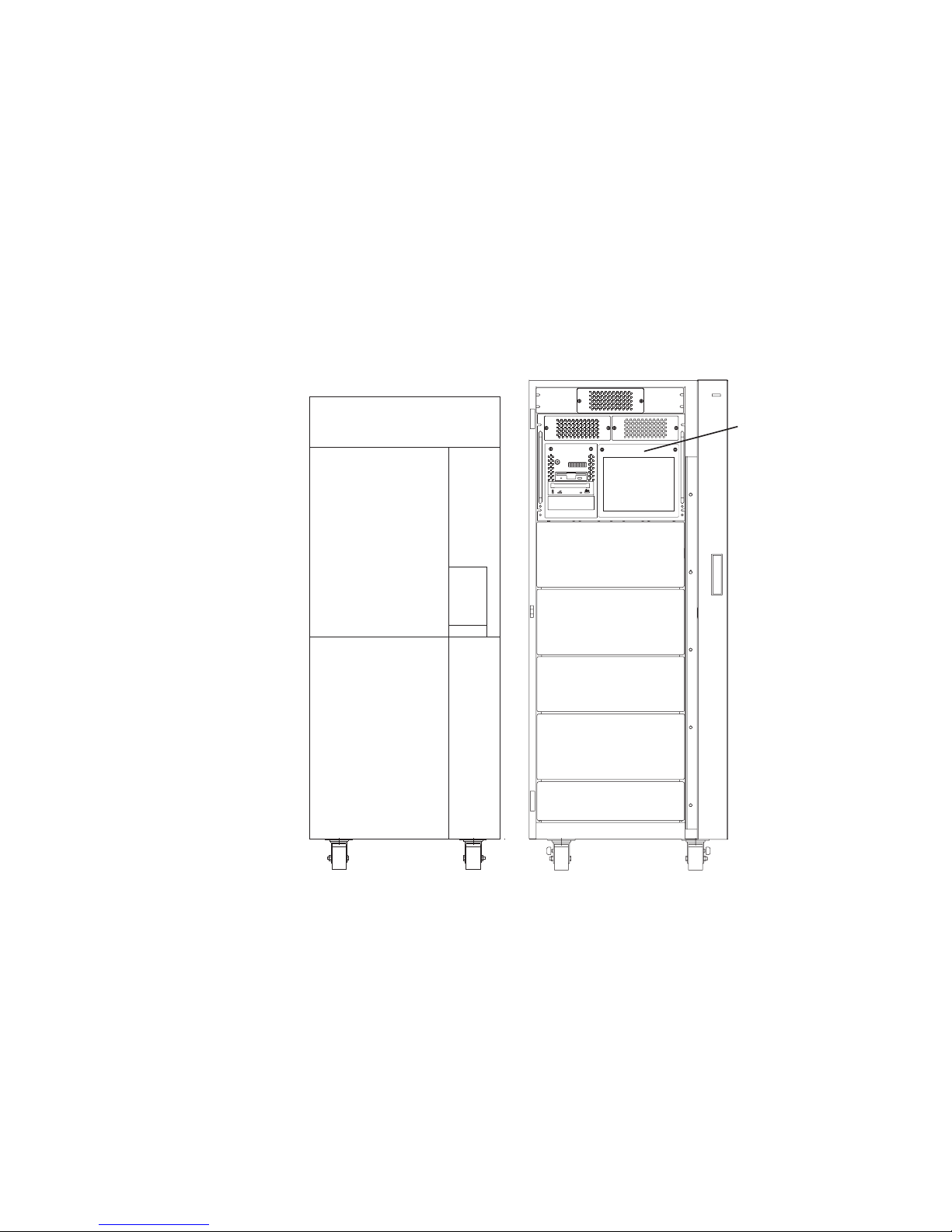
Models S80 and S85 Locations
Models S80 and S85 systems consist of a minimum of two racks — the system rack
and the input/output rack (I/O rack). These two components are connected by cables
that transmit data and control signals. Additional I/O racks can be added if further
expansion of the system is required. The following illustration shows the two racks.
System Rack
I/O Rack
6 Service Guide
Page 29
System and I/O Rack Configurations
Model S80 and S85 systems can be set up in various configurations regarding the
placement of the primary I/O drawer. Typically, the primary I/O drawer is installed in an
I/O rack with other drawers attached to the same system rack. If two systems are
installed side-by-side, then the two systems can share one I/O rack by installing both
primary I/O drawers in the same rack. This can be done to save space and also if the
systems are used for high-availability (HA) applications. The following illustrations show
some basic configurations.
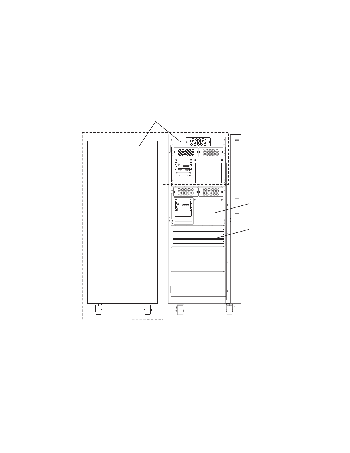
Basic Configuration with Primary I/O Drawer
Primary I/O Drawer
(Drawer 0)
Chapter 1. Reference Information 7
Page 30

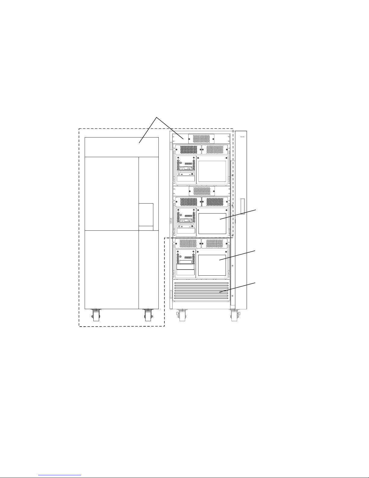
Basic Configuration with Two I/O Drawers
Primary I/O Drawer
(Drawer 0)
Secondary I/O Drawer
(Drawer 1)
8 Service Guide
Page 31

Two Systems Sharing One I/O Rack
Attention: If power is to be removed from one I/O drawer of a system that shares an
I/O rack with another system, ensure that the power is removed from the correct
drawer. Check the cabling before removing the power to make sure that you do not
disrupt the operation of the second system.
First System with Primary
I/O Drawer Installed in Top
Position of the I/O Rack
Second System with Primary
I/O Drawer Installed in the Lower
Position of the I/O Rack
Chapter 1. Reference Information 9
Page 32
Basic Configuration with H50 and H70 Sharing the I/O Rack
The I/O rack can also have other system drawers installed. The following illustrations
show configurations that allow systems drawers to be installed in the I/O rack along
with primary and secondary I/O drawers.
Primary I/O Drawer in Top Position
Note: Ensure that the cables from the I/O drawer are tied to the sides of the rack to
enable servicing of the system installed under the I/O drawers.
Follow the installation instructions for each system when the I/O rack is shared between
two system configuration types.
First System with Primary I/O Drawer
Installed in Top Position of the
I/O Rack
Second System Drawer
Installed Under Primary
I/O Drawer
Disk Drive Drawer
Installed Under Second
System Drawer
10 Service Guide
Page 33

Primary I/O Drawer in Lower Position
Note: Ensure that the cables from the upper drawers are tied to the sides of the rack
to enable servicing of the lower drawers.
Follow the installation instructions for each system when the I/O rack is shared between
two system configuration types.
First System with Primary I/O Drawer
Installed Under the Second System
Drawer.
Second System Drawer
Installed Over Primary
I/O Drawer
Disk Drive Drawer
Installed Under
Primary I/O Drawer
Chapter 1. Reference Information 11
Page 34
System with Two I/O Drawers and H50 and H70 Sharing the I/O Rack
Primary I/O Drawer in Top Position
Note: Ensure that the cables from the I/O drawers are tied to the sides of the rack to
enable servicing of the system drawer installed under the secondary I/O drawers.
Follow the installation instructions for each system when the I/O rack is shared between
two system configuration types.
First System with Primary I/O Drawer
Installed in Top Position of the
I/O Rack and a Secondary I/O Drawer
Installed Below the Primary I/O Drawer
Second System Drawer
Installed Under Secondary
I/O Drawer
Secondary I/O Drawer
Disk Drive Drawer
Installed Under Second
System Drawer
12 Service Guide
Page 35

Primary I/O Drawer in Lower Position
Note: Ensure that the cables from the upper drawers are tied to the sides of the rack
to enable servicing of the lower drawers.
Follow the installation instructions for each system when the I/O rack is shared between
two system configuration types.
First System with Primary and
Secondary I/O Drawers Installed
Under a Second System Drawer
in Top Position of the I/O Rack
Second System Drawer
Installed Over
Primary I/O Drawer
Primary I/O Drawer
Installed Under the
Second System Drawer
Secondary I/O Drawer
Installed Under the
Primary I/O Drawer
Disk Drive Drawer
Installed Under
Secondary I/O Drawer
Chapter 1. Reference Information 13
Page 36

System with One I/O Drawer, and Two H50 and H70s Sharing the I/O Rack
Primary I/O Drawer in Top Position
Note: Ensure that the cables from the I/O drawer are tied to the sides of the rack to
enable servicing of the system drawers installed under the I/O drawers.
Follow the installation instructions for each system when the I/O rack is shared between
two system configuration types.
First System with Primary I/O Drawer
Installed in Top Position of the
I/O Rack
Third System Drawer
Installed Under
Second System Drawer
Second System Drawer
Installed under
Primary I/O Drawer
Disk Drive Drawer
Installed Under
Third System Drawer
14 Service Guide
Page 37

Primary I/O Drawer in Lower Position
Note: Ensure that the cables from the upper drawers are tied to the sides of the rack
to enable servicing of the lower drawers.
Follow the installation instructions for each system when the I/O rack is shared between
two system configuration types.
First System with Primary I/O Drawer
Installed Under the Second System
Drawer
Primary I/O Drawer
Installed Under Second
System Drawer
Second System Drawer
Installed Over Primary
I/O Drawer
Secondary I/O Drawer
Installed under Primary
I/O Drawer
Disk Drive Drawer
Installed Under
Secondary I/O Drawer
Chapter 1. Reference Information 15
Page 38

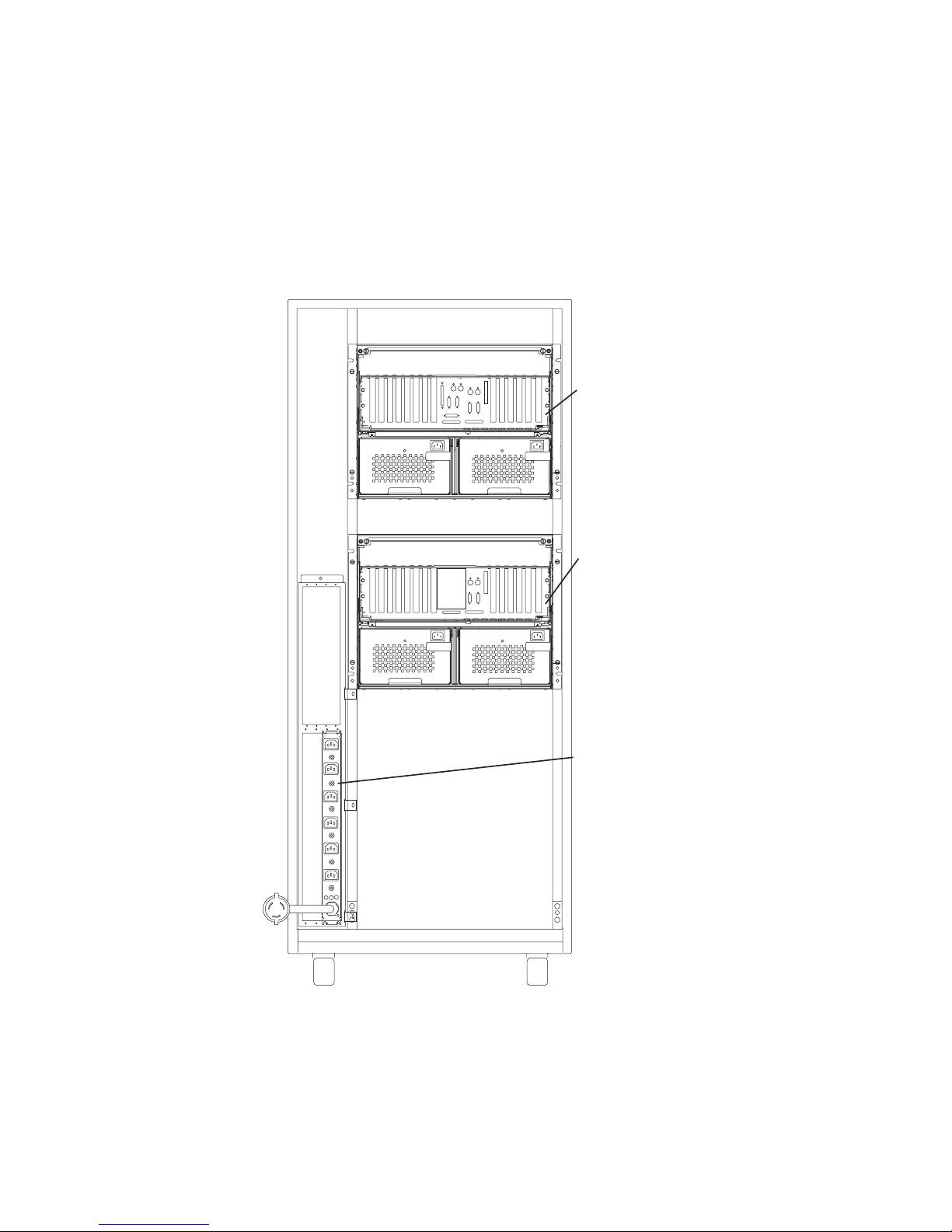
System Rack Locations
The following illustration shows locations for the front and rear views of the system
rack. More detailed locations for parts that are inside the covers of the system rack
follow.
Operator
Panel
JTAG
Connector
RIO Ports
Reserved
Connector
SPCN
Connectors
Blowers
Blowers
and
BulK Power
Supplies
Programmable
Regulators
Front Cage
SAMI Port
Rear Cage
AC Box
Front Rear
16 Service Guide
Page 39

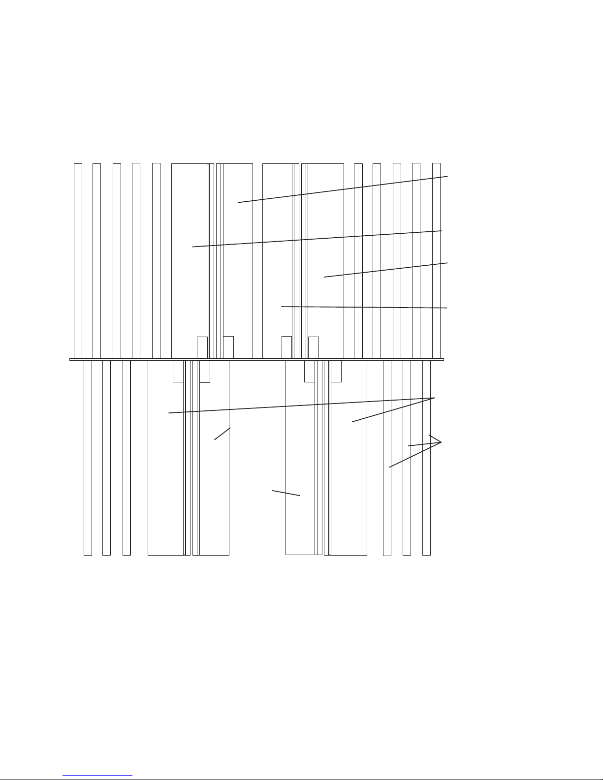
System Rack Locations Front
See the following illustration for component locations inside the front of the system rack.
┌──────────────────────────────────────────────────────────┐
├───┬───┬───┬─────┬─────┐ ┌─────┬─────┬───┬───┬───┤
││││ │ │ │ │ ││││
│ │ │ │B│P│ │P│P││││
│ │ │ │A│R│ │R│R││││
│ │ │ │S│O│ │O│O││││
│A│A│A│E│C│ │C│C│B│B│B│
││││ │ │ │ │ ││││
│ │ │ │P│C│ │C│R││││
│ │ │ │R│A│ │A│E││││
│ │ │ │O│R│ │R│G││││
│ │ │ │C│D│ │D│ ││││
││││ │ │ │ │ ││││
│ │ │ │R│0│ │2│19-24││││
│ │ │ │ E │ │ │ │Procs│ │ │ │
││││G│ │ │ │*││││
││││ │ │ │ │See││││
│ │ │ │ │ │ │ │ Note││││
│M│M│M│M│M│ │M│M│M│M│M│
│0│0│0│0│0│ │0│0│0│0│1│
│1│2│3│4│5│ │6│7│8│9│0│
├───┴───┴───┴─────┴─────┘ └─────┴─────┴───┴───┴───┤
│ Memory Memory │
││
│ Regulators │
│ ┌────┬────┬────┬────┬────┬────┬────┬────┬────┬────┐ │
│ │ P │ P │2.5V│ P │ P │ P │ P │ P 1│ P │ P │ │
││R │R │C │R │R │R │R │R9│R │R │ │
││O │O │P │O │O │O │O │O-│O │O │ │
││G │G │M │G │G │G │G │G2│G │G │ │
│││││││││4│││ │
││R│R│ │R│R│R│B│R│R│R│ │
││E │E │ │E │E │E │A │EP│E │E │ │
││G │G │ │G │G │G │S │GR│G │G │ │
││││││││E│O│││ │
│││││││││C│││ │
│││││││││*S│││ │
│ │R01 │R02 │R03 │R04 │R05 │R06 │R07 │R08 │R09 │R10 │ │
│ └────┴────┴────┴────┴────┴────┴────┴────┴────┴────┘ │
├────────────────────────────┬─────────────────────────────┤
││ │
│ BLOWER 1 │ BLOWER 2 │
│ B01 │ B02 │
│┌────────┬─────────┬────────┼────────┬─────────┬─────────┐│
││ Base │ Base │ Base │ Base │ 19-24 │ ││
││ │ │ │ │ PROCS │ ││
││ (BULK POWER SUPPLIES) │ ││
││ │ │ │ │ * │ Bulk ││
││ P01 │ P02 │ P03 │ P04 │ P05 │ Filler ││
└┴────────┴─────────┴────────┴────────┴─────────┴─────────┴┘
Note: Installed with Processor Card 3 (Slot M16).
Chapter 1. Reference Information 17
Page 40

System Rack Locations Rear
See the following illustration for component locations inside the rear of the system rack.
┌─────────────────────────────────────────────────────────────────┐
├───┬───┬───┬───┬───┬─────┬─────┐ ┌─────┬─────┬───┬───┬───┬───┬───┤
││││││ │ ││ │ ││││││
││││││P│IR││ P │CJ││││││
││││││R│/I││ R │LT││││││
││││││O│OO││ O │OA││││││
│B│C│C│C│C│ C │ ││ C │CG│D│D│D│D│A│
││││││ │HP││ │K││││││
││││││C│UO││ C │/P││││││
││││││A│BR││ A │PO││││││
││││││R│T││R│RR││││││
││││││D│CS││ D │OT││││││
││││││ │A││ │C││││││
││││││3│R││1│ ││││││
││││││ │D││ │R││││││
││││││ │ ││ │E││││││
││││││ │ ││ │G││││││
││││││ │ ││ │ ││││││
│M│M│M│M│M│M│M││M│M│M│M│M│M│M│
│1│1│1│1│1│1│1││1│1│2│2│2│2│2│
│1│2│3│4│5│6│7││8│9│0│1│2│3│4│
├───┴───┴───┴───┴───┴─────┴─────┘ └─────┴─────┴───┴───┴───┴───┴───┤
│ Memory Memory │
│ │
│ Regulators │
│ ┌────┐ │
││S││
││P││
││C││
││N││
││││
││C││
││A││
││R││
││D││
││││
│ │R21 │ │
│ └────┘ │
├───────────────────────────────┬─────────────────────────────────┤
││ │
││ │
│ BLOWER 3 │ BLOWER 4 │
│ B03 │ B04 │
││ │
│┌─────────────┬────────────────┼────────────────────────────────┐│
││ │ │ ││
││ │ │ AC Box ││
││ │ │ A01 ││
││ │ │ ││
││ │ │ ││
└┴─────────────┴────────────────┴────────────────────────────────┴┘
18 Service Guide
Page 41

I/O Rack Front Locations
The following illustration shows the front of an I/O rack. 10 EIA-Unit I/O Drawers can be
installed, as shown in the illustration.
I/O Drawers
10 EIA Unit I/O Drawers
Additional
Expansion
Positions
Chapter 1. Reference Information 19
Page 42
I/O Rack Rear Locations
The following illustration shows the rear of an I/O rack. 10 EIA-Unit I/O Drawers can be
installed, as shown in the illustration.
Power
Distribution
Bus
(CP1 - CP6)
Primary
I/O Drawer
10 EIA Unit I/O Drawers
Secondary
I/O Drawer
20 Service Guide
Page 43

I/O Drawer Locations
This section shows component locations for the 10 EIA-unit I/O drawer.
10 EIA-Unit I/O Drawer Front View
Note: The SCSI IDs shown for media devices indicate how installed devices will be set
when shipped from the factory.
1. Indicator Panel
2. Blower 1 (left)
3. Blower 3 (center)
4. Blower 2 (right)
5. Hot Swap Disk Drive Bays
6. Media Bay
Chapter 1. Reference Information 21
Page 44

10 EIA-Unit I/O Drawer Rear View
1. PCI adapter slots (1 - 7)
2. PCI adapter slot 8, service processor card and JTAG cable in primary I/O drawer
(drawer 0)
3. Parallel connector
4. Keyboard connector
5. Mouse connector
6. Reserved
7. Reserved
8. PCI adapter slots (9 - 14)
9. Right power supply
10. Power cord connector for right power supply
11. Fans (mounted on front end of right power supply)
12. Right power supply, power good LED
13. SPCN2 connector
14. SPCN1 connector
15. Serial port S2*
16. Serial port S1* (Used for TTY terminal connection)
22 Service Guide
Page 45

Note: In an RS/6000 SP environment, there is normally a cable attached from this
port to the SP Control Workstation. To directly attach a TTY terminal to this
port, the cable to the SP Control Workstation must be disconnected. Be
sure to reconnect this cable after servicing the system.
17. Operator panel (OP) connector
18. RIO 0 and RIO 1
19. Power cord connector for left power supply
20. Left power supply, power good LED
21. Fans (mounted on front end of left power supply)
22. Left power supply
* Serial ports 1 and 2 can only be used for service processor menus. No “heartbeat-”
type devices can be used on these ports.
Chapter 1. Reference Information 23
Page 46
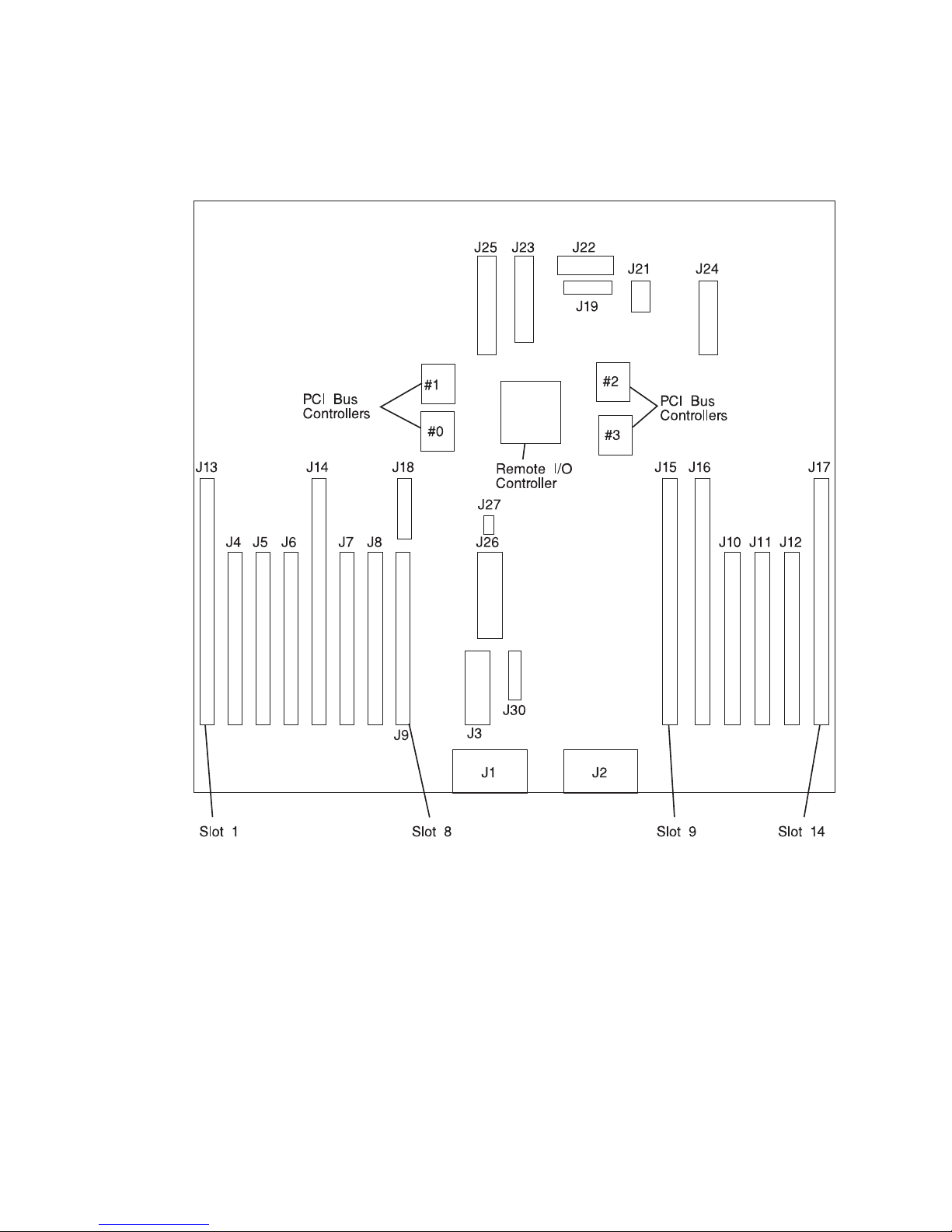
10 EIA-Unit I/O Drawer I/O Board Locations
J1 RIO bus
J2 RIO bus
J3 SPCN connector
J4 PCI slot 2, controller 1
J5 PCI slot 3, controller 1
J6 PCI slot 4, controller 1
J7 PCI slot 6, controller 0
J8 PCI slot 7, controller 0
J9 PCI slot 8, controller 0
J10 PCI slot 11, controller 2
J11 PCI slot 12, controller 2
J12 PCI slot 13, controller 2
J13 PCI slot 1, controller 1
J14 PCI slot 5, controller 0
24 Service Guide
Page 47
J15 PCI slot 9, controller 3
J16 PCI slot 10, controller 3
J17 PCI slot 14, controller 2
J18 JTAG connector
J19 Display indicator panel (DIP) connector
J21 I35 SCSI backplane connector
J22 Power distribution board (PDB) card connector
J23 PCI slot (1-8) power connector
J24 PCI slot (9-14) power connector
J25 +12 V dc, −12 V dc, and +3.3 V dc, power supply connector
J26 PCI slot power (1-8) +3.3 V dc power connector
J27 Speaker
J30 Reserved
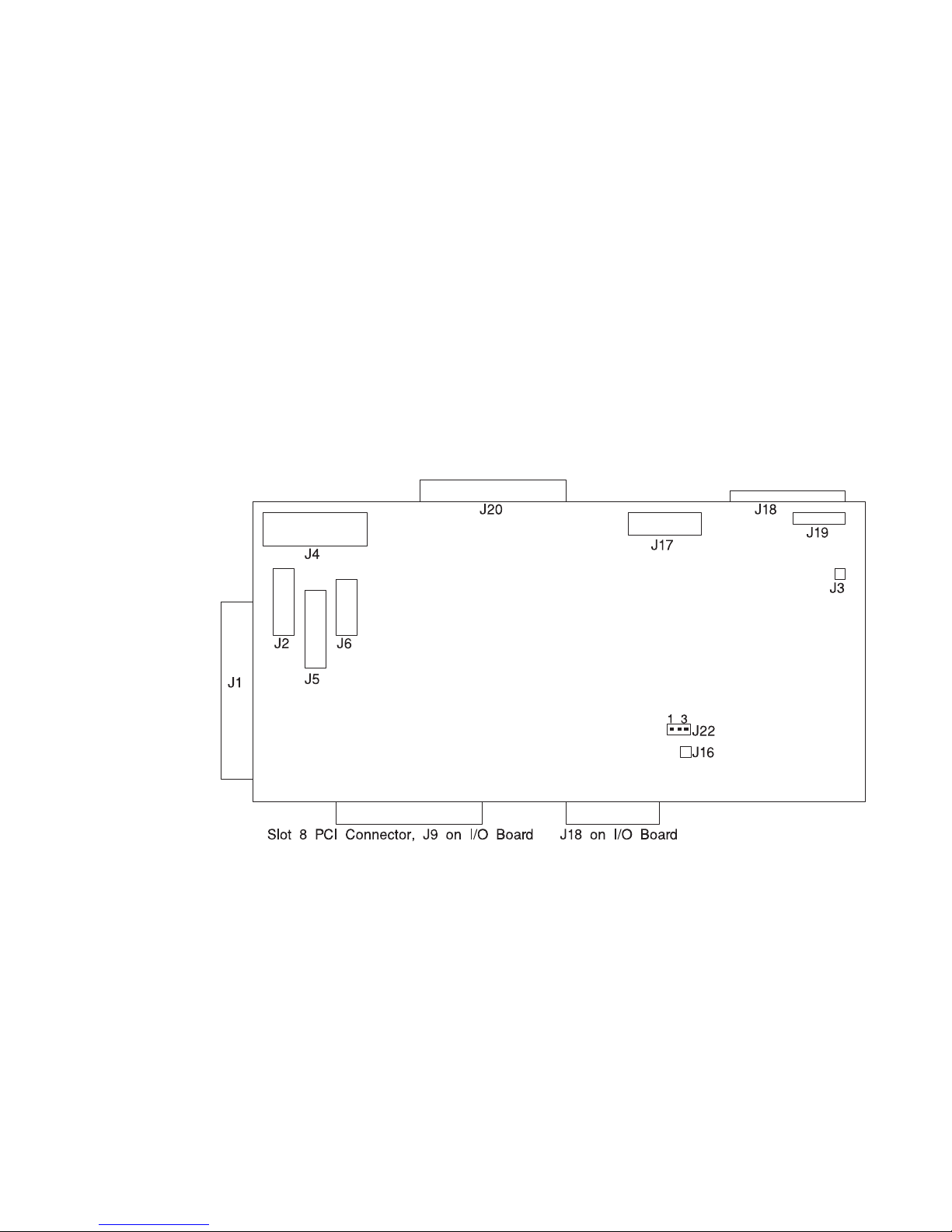
Service Processor Card Locations
J1 JTAG connector to system rack
J2 Serial port connector to inside bulkhead card
J3 Speaker connector
J4 Diskette drive connector
J5 Parallel Port connector
J6 Keyboard/mouse connector to inside bulkhead card
J16 Write protect DASD FLASH (if jumper is on pins)
J17 Operator panel connector from the system rack
J18 Test Port 0
J19 Test Port 1
J20 Test Port 2
J22 Write protect boot FLASH (if jumper is set between pins 2 and 3)
Chapter 1. Reference Information 25
Page 48
Fan Monitor Control (FMC) Card Locations (10 EIA-Unit I/O Drawer)
J1 To Power Distribution Board
J2 Fan 2 (Left Blower)
J3 Fan 1 (Center Blower)
J4 Fan 3 (Right Blower)
J5 Power Supply and Fans 4, 5, 6, 7 (Power Supply Fan Assemblies)
J6 To PCI Connectors
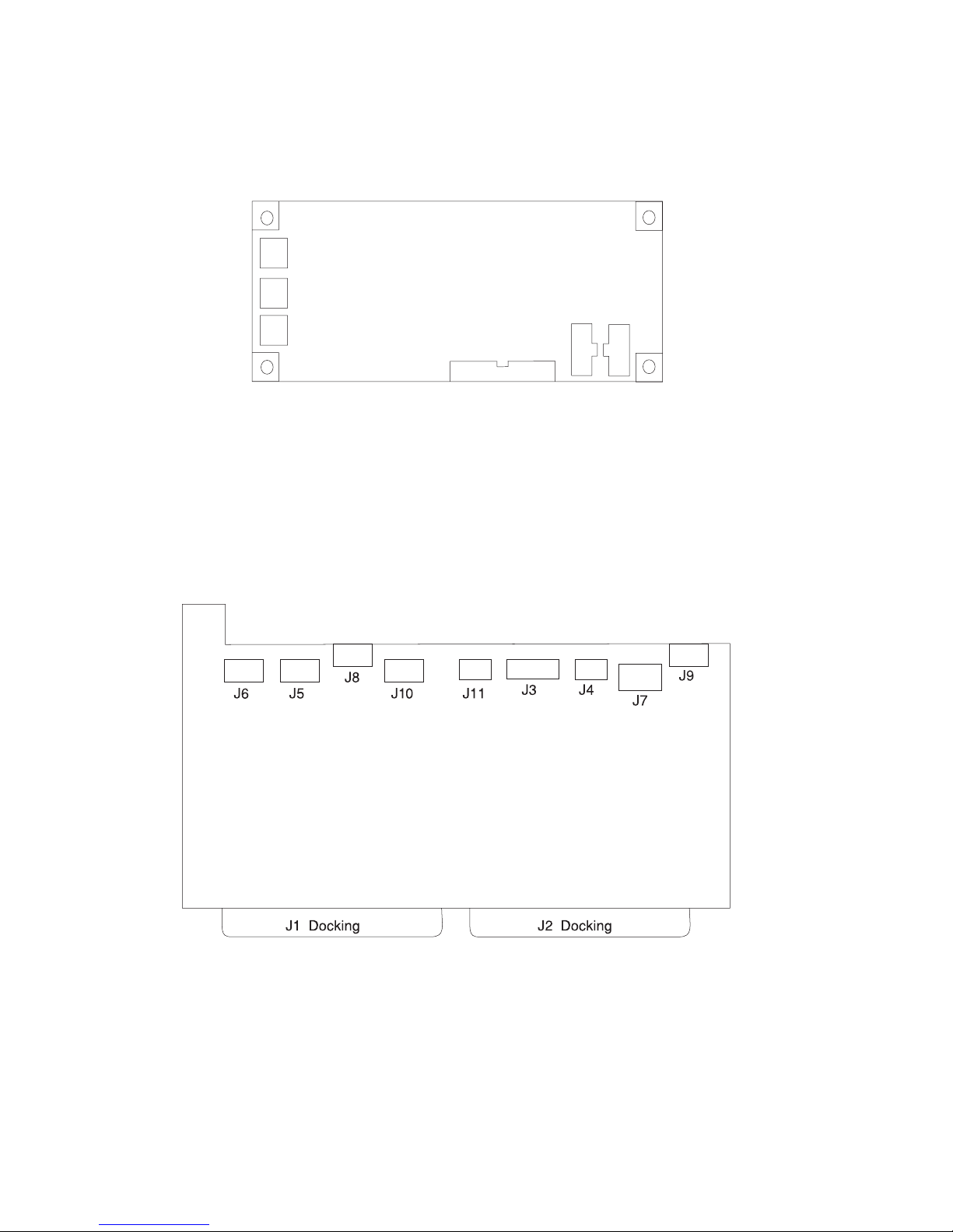
Power Distribution Board Locations
J1 Power supply docking connector
J2 Power supply docking connector
J3 I/O planar connector
J4 Fan monitoring card connector
J5 +12 V dc, −12Vdc
J6 +5Vdc
J7 +5Vdc
J8 I35 SCSI backplane power connector
J9 Media bay power connector
J5
J3
J2
J1
J4
J6
26 Service Guide
Page 49

J10 +5Vdc
J11 Fan monitoring card connector
System Memory
All system memory for the models S80 and S85 system is provided on several sizes of
memory cards, which are plugged into reserved slots.
There are 16 slots available for system memory, and they are located for easy access
from the front or rear of the system rack. These slots are shown in:
“System Rack Locations Front” on page 17
shows the relative positions to the system rack
“System Rack Locations Rear” on page 18
shows the relative positions to the system rack
“Memory Locations and Ordering Rules”
a top view including the processor and clock cards
The memory cards are M01 through M03 and M08 through M10 on the front of the
system, and M11 through M15 and M20 through M24 on the rear of the system.
Memory cards are available in several sizes: 256MB, 512MB, 1024MB, 2048MB, and
4096MB.
Memory Locations and Ordering Rules
The following illustration is a top-level view of the system memory. This view shows a
full configuration of memory cards installed into the system backplane.
R1 memory cards are used in models S80 and S85 systems. All memory cards are
installed in four-card functional units called quads. The quads must be composed of
four cards of the same type. The complete set of four cards must be properly installed
in the proper card slots for the newly installed memory to work correctly. See the
following illustration for the locations of the card slots that are in each quad.
Certain technical applications must have the memory configured for optimal
performance. The memory system of the models S80 and S85 is accessed through two
separate ports. Optimization is achieved by equalizing as much as possible the amount
of memory on each of the ports. Quads A and D are on one port. Quads B and C are
on the other port.
To upgrade the system for optimal performance, sort all of the memory features by
quad size, from largest to smallest. Install the largest memory feature in quad A, insert
the next largest memory feature in quad B. Continue inserting memory quads in the
available quads alphabetically, with the smaller features following the larger.
Chapter 1. Reference Information 27
Page 50
S
lot M
15
S
lo
tM
06
S
lo
tM
07
S
lo
tM
08
S
lot M
09
S
lot M
16
S
lo
tM
17
S
lo
tM
18
S
lo
tM
19
S
lo
tM
20
S
lo
tM
21
S
lo
t
M
22
S
lo
t
M
23
S
lo
tM
2
4
S
lo
tM
10
S
lo
t
M
05
S
lo
tM
04
S
lo
t
M
0
3
S
lo
t
M
02
S
lo
tM
01
Memory Quad
Memory Cards
Memory Quad
A BA
DCDCDCDB
BA
AC
B
System
Backplane
S
lo
t
M
1
1
S
lo
t
M
1
2
S
lo
tM
13
S
lot M
14
Rear of System Rack
Processor
Card 1
(Type 2 Card)
Processor
Card 3
(Type 2 Card)
Clock/Processor
Regulator Card
Processor
Regulator Cards
I/O Hub Card
Front of System Rack
Processor
Card 0
(Type 1 Card)
Processor
Card 2
(Type 2 Card)
28 Service Guide
Page 51
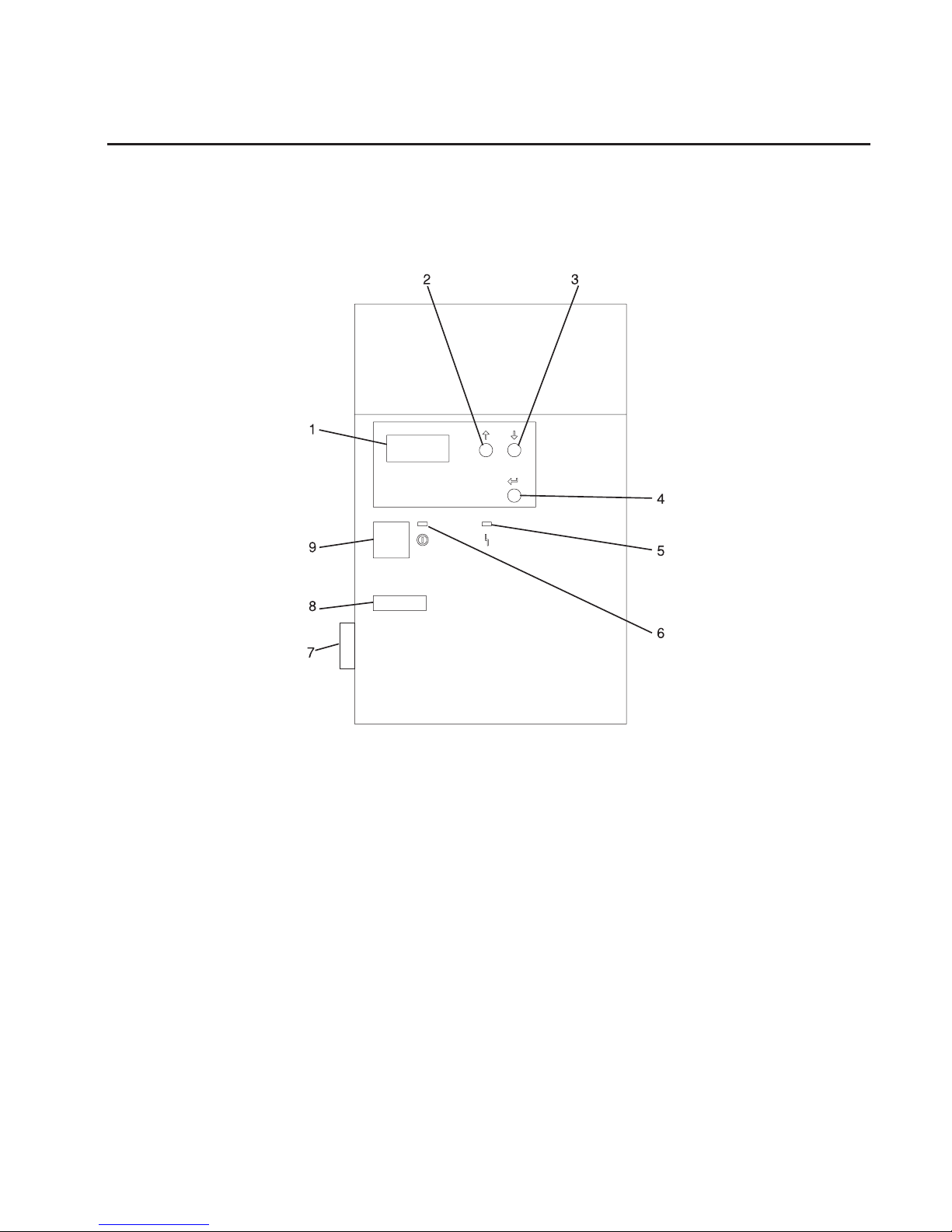
System Rack Operator Panel
The following illustration shows the locations of the operator panel display and the
operator panel pushbuttons. For details about the operator panel functions and
descriptions, see “Appendix C. Operator Panel Function Codes” on page 595.
1 Operator Panel Display
2 Scroll Up Pushbutton
3 Scroll Down Pushbutton
4 Enter Pushbutton
5 Attention LED
6 Power-On LED
7 SAMI Port. This port is used when connecting an models S80 and S85 in an
RS/6000 SP environment.
8 Serial Number
9 Power Pushbutton
Chapter 1. Reference Information 29
Page 52

I/O Drawer Indicator Panel
This section describes the indicator panel located on the I/O drawer.
10 EIA-Unit I/O Drawer Indicator Panel
1 Power-On LED
2 Drawer Indicator Panel Display
10 EIA-Unit I/O Drawer and Power Supply LED Status
State of LED Display Indicator
Panel LED
Right Power Supply
LED
Left Power Supply
LED
Off No power connected No power connected No power connected
On, blinking green System power
connected, not turned
on
System power
connected, not turned
on
System power
connected, not turned
on
On, steady green System power
connected and turned
on
System power
connected and turned
on
System power
connected and turned
on
10 EIA-Unit I/O Drawer Indicator Panel Status
Drawer State LED Drawer Indicator Panel
After Connecting ac Power
Standby Blinking Blinking location U?.?
System power On solid Blinking location U?.?
Receive Firmware Command On solid On solid location Ux.y#
Thereafter On solid On solid location Ux.y#
After Power is Removed Because of a Shutdown
Standby Blinking Blinking location Ux.y
System power Solid Blinking location Ux.y
Receive Firmware Command Solid Solid location Ux.y#
Thereafter Solid Solid location Ux.y#
# represents a blinking asterisk (*)
30 Service Guide
Page 53

Cabling the System Rack and I/O Rack
The minimum system consists of two racks. The system rack contains the system
processors, memory, and supporting hardware. The I/O rack contains I/O drawer(s) with
PCI adapters, disk drives, and media drives. The models S80 and S85 must have a
minimum of one I/O drawer. This primary I/O drawer contains the service processor for
the system. Additional I/O drawers can be added to the system. These secondary I/O
drawers are connected to the system rack but do not contain a service processor. The
models S80 and S85 supports up to a total of four I/O drawers in different I/O rack
configurations.
Use the following steps to connect the system rack to the I/O drawers in their I/O racks:
1. Connect the JTAG cable and the operator panel cable. These two cables are
connected only between the system rack and the primary I/O drawer. See
“Connecting JTAG and Operator Panel Cables” on page 32 for illustrations showing
these cables.
2. Connect the RIO cables, and the SPCN cables. These cables connect between the
system rack and all the I/O drawers in loops. See “Connecting RIO and SPCN
Cables” on page 32 for illustrations showing these cables.
Chapter 1. Reference Information 31
Page 54

Connecting JTAG and Operator Panel Cables
Use the following illustration to connect the JTAG and operator panel (OP) cables.
Connecting RIO and SPCN Cables
The RIO and SPCN cables provide two functions in the models S80 and S85 system:
remote data bus connection and power control. The following rules must be followed
when connecting these two types of cables:
v The I/O drawers must be connected in a loop fashion for both the RIO cables and
the SPCN cables. The loop connection provides redundant paths so that if a failure
occurs in part of a cable, the system will continue to operate. If a failure occurs, a
warning message displays on the system console but the system continues to
operate.
v One loop is required for the SPCN cabling. This loop begins and ends at the system
rack.
v Two loops are possible for the RIO cabling depending on the number and desired
configuration of I/O drawers. These loops begin and end at the system rack.
OP
Front of System Rack
Rear of Primary
I/O Drawer (Drawer 0)
Rear of Primary
I/O Drawer (Drawer 0)
Rear of System Rack
Operator Panel
Connector
SAMI Port
Slot 8
Service Processor Connector
JTAG
Connector
32 Service Guide
Page 55

RIO Cabling
The following rules apply to RIO cable connections:
v I/O drawers 0 and 1 are connected using the first RIO loop, which uses RIO ports 0
and 1 on the system rack.
v I/O drawers 2 and 3 are connected using the second RIO loop, which uses RIO ports
2 and 3 on the system rack.
v The primary I/O drawer must be installed and connected to RIO port 0 of the system
rack. The connection must be made from RI0 port 0 of the system rack to RIO port 0
of the primary I/O drawer. This connection is required to make the primary drawer the
first drawer in the loop, which allows the firmware to initialize the system.
v If the loop connection between RIO 2 and RIO 3 is broken, the system is not able to
differentiate between I/O drawer 2 and I/O drawer 3. The system still conillustrations
RIO 0 and RIO 1 ports, but does not conillustration RIO 2 or RIO 3 ports.
The following illustrations provide cabling examples for all valid cabling configurations.
Match your configuration to the correct illustration and connect your RIO cables as
shown.
System Rack Attached to One I/O Drawer
21
SPCN
RIO 1RIO 0
Drawer 0, Primary
RIO 1
RIO 0
RIO 2
RIO 3
J14
J11
SPCN 0, J15
SPCN 1, J16
Chapter 1. Reference Information 33
Page 56

System Rack Attached to Two I/O Drawers
Either of the following cabling configurations can be used for a system rack attached to
two I/O drawers.
OR
RIO 1RIO 0
21
SPCN
21
SPCN
RIO 1RIO 0
Drawer 0
Drawer 1
RIO 1
RIO 0
RIO 2
RIO 3
J14
J11
SPCN 0, J15
SPCN 1, J16
RIO 1RIO 0
21
SPCN
21
SPCN
RIO 1RIO 0
Drawer 0
Drawer 2
RIO 1
RIO 0
RIO 2
RIO 3
J14
J11
SPCN 0, J15
SPCN 1, J16
34 Service Guide
Page 57

System Rack Attached to Three I/O Drawers
System Rack Attached to Four I/O Drawers
RIO 1RIO 0
21
SPCN
221
1
SPCN
SPCN
RIO 1
RIO 1
RIO 0
RIO 0
Drawer 0
Drawer 1
Drawer 2
RIO 1
RIO 0
RIO 2
RIO 3
J14
J11
SPCN 0, J15
SPCN 1, J16
RIO 1
RIO 1
RIO 0
RIO 0
221
1
SPCN
SPCN
221
1
SPCN
SPCN
RIO 1
RIO 1
RIO 0
RIO 0
Drawer 0
Drawer 1
Drawer 2
Drawer 3
RIO 1
RIO 0
RIO 2
RIO 3
J14
J11
SPCN 0, J15
SPCN 1, J16
Chapter 1. Reference Information 35
Page 58

SPCN Cabling
The following illustrations provide cabling examples for all valid cabling configurations.
Match your configuration to the correct illustration and connect your SPCN cables as
shown.
System Rack Attached to One I/O Drawer
System Rack Attached to Two I/O Drawers
21
SPCN
RIO 1RIO 0
Drawer 0
RIO 1RIO 0
RIO 2 RIO 3
J14
J11
SPCN 0, J15
SPCN 1, J16
RIO 1RIO 0
21
SPCN
21
SPCN
RIO 1RIO 0
Drawer 0
Drawer 1 or 2
RIO 1
RIO 0
RIO 2 RIO 3
J14
J11
SPCN 0, J15
SPCN 1, J16
36 Service Guide
Page 59

System Rack Attached to Three I/O Drawers
System Rack Attached to Four I/O Drawers
RIO 1RIO 0
21
SPCN
Drawer 1
Drawer 2
RIO 1RIO 0
21
SPCN
21
SPCN
RIO 1RIO 0
Drawer 0
RIO 1
RIO 0
RIO 2 RIO 3
J14
J11
SPCN 0, J15
SPCN 1, J16
RIO 1
RIO 1
RIO 0
RIO 0
221
1
SPCN
SPCN
Drawer 1
Drawer 2
Drawer 3
RIO 1RIO 0
21
SPCN
21
SPCN
RIO 1RIO 0
Drawer 0
RIO 1
RIO 0
RIO 2 RIO 3
J14
J11
SPCN 0, J15
SPCN 1, J16
Chapter 1. Reference Information 37
Page 60

Models S80 and S85 Power Overview
The models S80 and S85 power is provided to each rack type by independent power
supplies and distribution cabling. Both the system racks require 200 to 240 V ac power
connections. The system rack and the I/O rack have independent power distribution
systems.
System Rack Power
The power enters the processor system rack as 200-240 V ac. The line cord enters the
ac box, which contains two components; one is the ac filter and distribution assembly,
and the other supplies standby power to some system components. Standby power is
supplied to the operator panel interface and the System Power Control Network
(SPCN).
The filtered 200-240 V ac is then sent to the four (five on fully configured systems)
system bulk power supplies. The supplies are coupled together and provide an N+1
level of redundancy for protection. N+1 refers to the fact that because the supplies are
coupled to a common distribution bus, if one of the supplies fails, the system will not
fail. The bulk supplies provide a positive 29-volt output, which is fed to the system
regulator located above the bulk supplies and to the system blowers.
The system blowers maintain the system temperature within the strict guidelines
required in an N+1 arrangement. Each blower can be powered off individually so that a
blower can be removed and replaced without turning off the system power. The blowers
only require +29 V dc.
The system regulators provide 2.5 V dc and 3.3 V dc to the system.
I/O Rack Power
The I/O rack power-distribution network is shown in the illustration found under “I/O
Drawer Cabling” on page 41.
Power enters the I/O rack as 200-240 V ac through a power cable assembly and
terminates on a power distribution bus (PDB). The PDB has six individual ac outlets,
each capable of eight amps at 200-240 V ac, which are overload-protected and
resettable. Each I/O drawer is supplied from one ac outlet of the PDB through a special
“Y” cable. The “Y” cable draws power from a single PDB outlet and provides a standard
ac plug to each of the two power supplies used in each I/O drawer. Two I/O drawers
are allowed in each rack, but other type drawers can be installed in addition to the two
I/O drawers.
Ten EIA-unit I/O drawers have two redundant power supplies. One of these power
supplies is capable of providing the necessary voltages and currents independently of
the other. The left and right power supply output voltages are connected together and
monitored by the power distribution board contained in the 10 EIA-unit I/O drawer.
The left and right power supplies are hot-pluggable and may be changed one-at-a-time
while the system is operational. Each power supply provides 5 V dc, 3.3 V dc, 12 v dc,
and5Vdcstandby.
38 Service Guide
Page 61

The5Vdcstandby power is provided by both power supplies and connected together
on the I/O planar directly because the power supplies contain overload protection
against one supply shorting the other. Standby power of +5 V dc is provided to a
portion of the I/O planar, which is part of the system SPCN logic. This consists of
several components, including a logic chip, ROM, SRAM, and transceivers. The service
processor is not on standby power. Both power supplies provide +12 V dc to the fans in
the drawer to ensure sufficient cooling if one of the supplies fails. However, the
short-circuit prevention is on the I/O planar to protect against inadvertent shorts in one
line, causing the +12 V dc to fail completely.
Chapter 1. Reference Information 39
Page 62

Models S80 and S85 Cabling
The following illustration shows the internal cabling for the models S80 and S85.
System Rack
System
Rack
I/O Drawer
I/O
Drawer
I/O Planar
Clock/Processor
Regulator Card
40 Service Guide
Page 63

I/O Drawer Cabling
The following illustration shows the routing for power cables in the 10 EIA-unit I/O
drawer.
Chapter 1. Reference Information 41
Page 64
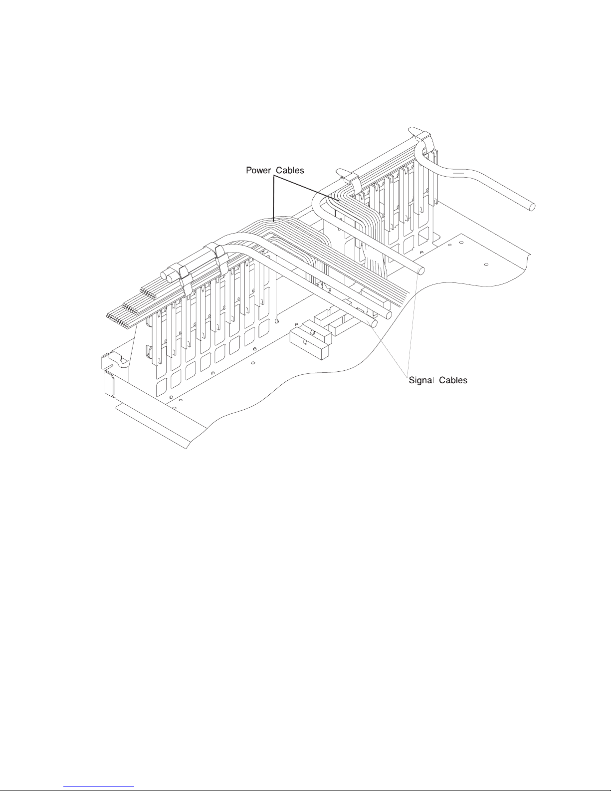
10 EIA-Unit I/O Drawer Cable Routing
Attention: Take care to route power and signal cables on the top of the I/O adapter
support. To keep the air-entry cutouts open in the drawer and to help prevent adapters
from overheating, retain the cables with unlocking wire ties as shown.
SCSI IDs and Bay Locations
The following illustrations show the SCSI IDs for media and disk drives. The SCSI IDs
for media devices installed in bank A at the factory are set using jumpers on the drives
when they are installed. The SCSI IDs are set as shown in the following illustration.
The SCSI IDs for the hot-swap disk drives installed in banks C and D are set when the
drive is installed. There are no SCSI jumpers to set; the SCSI ID is controlled by the
position in which the drive is installed.
42 Service Guide
Page 65

10 EIA-Unit I/O Drawer SCSI IDs
Note: The SCSI IDs shown for media indicate how installed devices are set when
shipped from the factory.
Chapter 1. Reference Information 43
Page 66

Location Codes
This system unit uses physical location codes in conjunction with AIX location codes to
provide mapping of the failing field replaceable units. The location codes are produced
by the system unit’s firmware and AIX.
Physical Location Codes
Physical location codes provide a mapping of logical functions in a platform (or
expansion sites for logical functions, such as connectors or ports) to their specific
locations within the physical structure of the platform.
Location Code Format
The location code is an alphanumeric string of variable length, consisting of a series of
location identifiers, separated by a dash (-), or slash (/), or a pound sign (#) character.
The series is hierarchical; that is, each location identifier in the string is a physical or
logical child of the one preceding it.
v The - (dash) separator character represents a normal structural relationship where
the child is a separate physical package and it plugs into (or is connected to) the
parent. For example, P1-C1 is a processor card (C1) plugged into a planar (P1), or
P1-M1 is a memory card (M1) plugged into a planar (P1).
v The / (slash) separator character separates the base location code of a function from
any extended location information. A group of logical devices can have the same
base location code because they are all on the same physical package, but may
require extended location information to describe the connectors they support. For
example, P2/S1 describes the location of the serial port 1 controller and its connector
(S1), which is located on planar P2 (its base location code), but the / indicates that
further devices can be connected to it at the external S1 serial connector. The
keyboard controller and its connector likewise have location code P2/K1, which
means they have the same base location code (P2) as serial port 1, but a different
external connector. In contrast, the location code P2-K1 actually points to the device
connected to connector K1; that is, the keyboard. The location code P2/Z1 indicates
an integrated SCSI controller which drives connector Z1, while location codes of
P2-Z1-... point to the actual SCSI bus and devices.
v The # (pound sign) separator character indicates a cable connection between a
connector and parent.
The following are examples:
v P1-C1 identifies processor card C1 plugged into planar P1.
v P1-M1 identifies memory card M1 plugged into planar P1.
v P2/S1 identifies serial port 1 controller on I/O board P2 or the connector for serial
port 1.
v P1-K1 identifies a keyboard attached to connector K1 on planar P1.
v P2/Z1 identifies an integrated SCSI port controller on planar P2 which drives
connector Z1.
v P2-Z1-... points to the actual SCSI bus and devices attached to Z1.
44 Service Guide
Page 67

The . (period) identifies sublocations (DIMMs on a memory card or SCSI addresses).
The following are examples:
v P1-M1.4 identifies memory DIMM 4 on memory card 1 plugged into planar P1.
v P1-C1.1 identifies processor 1 on processor card 1 plugged into planar P1.
v P2-Z1-A3.1 identifies a SCSI device with SCSI address of LUN 1 at SCSI ID 3
attached to SCSI bus 1, which is integrated on planar P2.
v P2.1 identifies a riser card plugged into planar P2.
AIX Location Codes
The basic formats of the AIX location codes are as follows:
v For non-SCSI devices/drives:
– AB-CD-EF-GH
v For SCSI devices/drives:
– AB-CD-EF-G,H
Non-SCSI Devices/Drives
For planars, cards, and non-SCSI devices, the location code is defined as follows:
AB-CD-EF-GH
||||
| | | Device/FRU/Port ID
| | Connector ID
| devfunc Number, Adapter Number or Physical Location
Bus Type or PCI Parent Bus
v The AB value identifies a bus type or PCI parent bus as assigned by the firmware.
v The CD value identifies adapter number, the adapter’s devfunc number, or physical
location. The devfunc number is defined as the PCI device number times 8, plus the
function number.
v The EF value identifies a connector.
v The GH value identifies a port, address, device, or FRU.
Adapters and cards are identified only with AB-CD.
The possible values for AB are:
00 Processor bus
01 ISA bus
02 EISA bus
03 MCA bus
04 PCI bus used in the case where the PCI bus cannot be identified
05 PCMCIA buses
xy For PCI adapters where x is equal to or greater than 1. The x and y are characters in the
range of 0-9, A-H, J-N, P-Z (O, I, and lower case are omitted) and are equal to the parent
bus’s ’ibm, aix-location’ open firmware property.
The possible values for CD depend on the adapter/card:
Chapter 1. Reference Information 45
Page 68

v For pluggable PCI adapters/cards, CD is the device’s devfunc number (PCI device
number times 8, plus the function number). The C and D are characters in the range
of 0-9, and A-F (hex numbers). Location codes therefore uniquely identify multiple
adapters on individual PCI cards.
v For pluggable ISA adapters, CD is equal to the order of the ISA cards
defined/configured either by SMIT or the ISA Adapter Configuration Service Aid.
v For an integrated ISA adapters, CD is equal to a unique code identifying the ISA
adapter. In most cases, this code is equal to the adapter’s physical location code. In
cases where a physical location code is not available, CD will be FF.
EF is the connector ID. It is used to identify the adapter’s connector to which a resource
is attached.
GH is used to identify a port, device, or FRU. For example:
v For async, devices GH defines the port on the fanout box. The values re 00 a to 15.
v For a diskette drive, H identifies either diskette drive 1 or 2. G is always 0.
v For all other devices, GH is equal to 00.
For an integrated adapter, EF-GH is the same as the definition for a pluggable adapter.
For example, the location code for a diskette drive is 01-D1-00-00. A second diskette
drive is 01-D1-00-01.
SCSI Devices/Drives
For SCSI devices, the location code is defined as follows:
AB-CD-EF-G,H
| | |||
| | | | Logical Unit address of the SCSI Device
| | | Control Unit Address of the SCSI Device
| | Connector ID
| devfunc Number, Adapter Number or Physical Location
Bus Type or PCI Parent Bus
Where AB-CD-EF are the same as non-SCSI devices.
G defines the control unit address of the device. Values of 0 to 15 are valid.
H defines the logical unit address of the device. Values of 0 to 255 are valid.
A bus location code is also generated as ’00-XXXXXXXX’ where XXXXXXXX is
equivalent to the node’s unit address.
Examples of physical location codes displayed by AIX are as follows:
v First processor card plugged into planar 1:
P1-C1
46 Service Guide
Page 69

v Second memory card in planar P1:
P1-M2
v Memory DIMM 12 on second memory card plugged into planar P1:
P1-M2.12
Examples of AIX location codes displayed are as follows:
v Integrated PCI adapter:
10-80 Ethernet
10-60 Integrated SCSI Port 1 (internal)
10-88 Integrated SCSI Port 2 (external)
v Pluggable PCI adapters:
20-58 to 20-5F Any PCI card in slot 1
20-60 to 20-67 Any PCI card in slot 2
10-68 to 10-6F Any PCI card in slot 3
10-70 to 10-77 Any PCI card in slot 4
10-78 to 10-7F Any PCI card in slot 5
v Integrated ISA adapters:
01-D1 Diskette adapter
01-R1 Parallel port adapter
01-S1 Serial port 1 adapter
01-S2 Serial port 2 adapter
01-S3 Serial port 3 adapter
01-K1 Keyboard adapter
v Device attached to SCSI controller:
10-60-00-4,0 Device attached to integrated SCSI Port 1
Chapter 1. Reference Information
47
Page 70

AIX and Physical Location Code Reference Tables
The following tables contain location codes that are used to identify functional units in
the models S80 and S85 systems. Each table below shows the locations for a physical
part of the system.
System Rack
FRU Name Slot
Name
Location Code AIX Location
Code
Physical
Connection
Logical
Connection
System Rack U1 00-00
System
Backplane
U1.1-P1 00-00
Memory
Controller
U1.1-P1 00-00 On System
Backplane
Operator Panel U1.1-P1-L1
Processor
Regulator 21
M04 U1.1-P1-V1
Processor
Regulator 22
M07 U1.1-P1-V2
I/O Hub Card M17 U1.1-P1-X1 00-00 On System
Backplane
RIO Port 0
Connector/Cable
U1.1-P1-X1/Q1
RIO Port 1
Connector/Cable
U1.1-P1-X1/Q2
RIO Port 2
Connector/Cable
U1.1-P1-X1/Q3
RIO Port 3
Connector/Cable
U1.1-P1-X1/Q4
R1 Memory Card
Quad A, Front
M01 U1.1-P1-M1 00-00 System
Backplane
R1 Memory Card
Quad A, Front
M02 U1.1-P1-M2 00-00 System
Backplane
R1 Memory Card
Quad A, Front
M03 U1.1-P1-M3 00-00 System
Backplane
R1 Memory Card
Quad B, Front
M08 U1.1-P1-M4 00-00 System
Backplane
R1 Memory Card
Quad B, Front
M09 U1.1-P1-M5 00-00 System
Backplane
R1 Memory Card
Quad B, Front
M10 U1.1-P1-M6 00-00 System
Backplane
Clock/Processor
Regulator 23
Rear
M19 U1.1-P1-X2 00-00 System
Backplane
48 Service Guide
Page 71

FRU Name Slot
Name
Location Code AIX Location
Code
Physical
Connection
Logical
Connection
Processor Card 0
Type 1, Front
M05 U1.1-P1-C1 System
Backplane
Processor Card 0
All Cache
U1.1-P1-C1 00-00 On Processor
Card 0
Processor Card 0
Processor 0
U1.1-P1-C1 00-00 On Processor
Card 0
Processor Card 0
Processor 1
U1.1-P1-C1 00-01 On Processor
Card 0
Processor Card 0
Processor 2
U1.1-P1-C1 00-02 On Processor
Card 0
Processor Card 0
Processor 3
U1.1-P1-C1 00-03 On Processor
Card 0
Processor Card 0
Processor 4
U1.1-P1-C1 00-04 On Processor
Card 0
Processor Card 0
Processor 5
U1.1-P1-C1 00-05 On Processor
Card 0
Processor Card 1
Type 2, Rear
M18 U1.1-P1-C2 System
Backplane
Processor Card 1
All Cache
U1.1-P1-C2 00-00 On Processor
Card 1
Processor Card 1
Processor 6
U1.1-P1-C2 00-06 On Processor
Card 1
Processor Card 1
Processor 7
U1.1-P1-C2 00-07 On Processor
Card 1
Processor Card 1
Processor 8
U1.1-P1-C2 00-08 On Processor
Card 1
Processor Card 1
Processor 9
U1.1-P1-C2 00-09 On Processor
Card 1
Processor Card 1
Processor 10
U1.1-P1-C2 00-10 On Processor
Card 1
Processor Card 1
Processor 11
U1.1-P1-C2 00-11 On Processor
Card 1
R1 Memory Card
Quad B, Rear
M11 U1.1-P1-M7 00-00 System
Backplane
R1 Memory Card
Quad C, Rear
M12 U1.1-P1-M8 00-00 System
Backplane
R1 Memory Card
Quad C, Rear
M13 U1.1-P1-M9 00-00 System
Backplane
R1 Memory Card
Quad C, Rear
M14 U1.1-P1-M10 00-00 System
Backplane
R1 Memory Card
Quad C, Rear
M15 U1.1-P1-M11 00-00 System
Backplane
Chapter 1. Reference Information
49
Page 72

FRU Name Slot
Name
Location Code AIX Location
Code
Physical
Connection
Logical
Connection
R1 Memory Card
Quad D, Rear
M20 U1.1-P1-M12 00-00 System
Backplane
R1 Memory Card
Quad D, Rear
M21 U1.1-P1-M13 00-00 System
Backplane
R1 Memory Card
Quad D, Rear
M22 U1.1-P1-M14 00-00 System
Backplane
R1 Memory Card
Quad D, Rear
M23 U1.1-P1-M15 00-00 System
Backplane
R1 Memory Card
Quad A, Rear
M24 U1.1-P1-M16 00-00 System
Backplane
Processor Card 2
Type 2, Front
M06 U1.1-P1-C3 System
Backplane
Processor Card 2
All Cache
U1.1-P1-C3 00-00 On Processor
Card 2
Processor Card 2
Processor 12
U1.1-P1-C3 00-12 On Processor
Card 2
Processor Card 2
Processor 13
U1.1-P1-C3 00-13 On Processor
Card 2
Processor Card 2
Processor 14
U1.1-P1-C3 00-14 On Processor
Card 2
Processor Card 2
Processor 15
U1.1-P1-C3 00-15 On Processor
Card 2
Processor Card 2
Processor 16
U1.1-P1-C3 00-16 On Processor
Card 2
Processor Card 2
Processor 17
U1.1-P1-C3 00-17 On Processor
Card 2
Processor Card 3
Type 2, Rear
M16 U1.1-P1-C4 System
Backplane
Processor Card 3
All Cache
U1.1-P1-C4 00-00 On Processor
Card 3
Processor Card 3
Processor 18
U1.1-P1-C4 00-18 On Processor
Card 3
Processor Card 3
Processor 19
U1.1-P1-C4 00-19 On Processor
Card 3
Processor Card 3
Processor 20
U1.1-P1-C4 00-20 On Processor
Card 3
Processor Card 3
Processor 21
U1.1-P1-C4 00-21 On Processor
Card 3
Processor Card 3
Processor 22
U1.1-P1-C4 00-22 On Processor
Card 3
Processor Card 3
Processor 23
U1.1-P1-C4 00-23 On Processor
Card 3
Power Backplane U1.1-P2
50 Service Guide
Page 73

FRU Name Slot
Name
Location Code AIX Location
Code
Physical
Connection
Logical
Connection
Regulator Card
Front
R01 U1.1-P2-V1 Power
Backplane
Regulator Card
Front
R02 U1.1-P2-V2 Power
Backplane
Regulator Card
Front
R03 U1.1-P2-V3 Power
Backplane
Regulator Card
Front
R04 U1.1-P2-V4 Power
Backplane
Regulator Card
Front
R05 U1.1-P2-V5 Power
Backplane
Regulator Card
Front
R06 U1.1-P2-V6 Power
Backplane
Regulator Card
Front
R07 U1.1-P2-V7 Power
Backplane
Regulator Card
Front
R08 U1.1-P2-V8 Power
Backplane
Regulator Card
Front
R09 U1.1-P2-V9 Power
Backplane
Regulator Card
Front
R10 U1.1-P2-V10 Power
Backplane
SPCN Card Rear R21 U1.1-P2-X1 Power
Backplane
Blower 1 Sense 1 U1.1-P2-X1/F1 On SPCN Card
Blower 2 Sense 2 U1.1-P2-X1/F2 On SPCN Card
Blower 3 Sense 3 U1.1-P2-X1/F3 On SPCN Card
Blower 4 Sense 4 U1.1-P2-X1/F4 On SPCN Card
Blower 1 Front B01 U1.2-F1 Power
Harness, J18
Blower 2 Front B02 U1.2-F2 Power
Harness, J19
Blower 3 Rear B03 U1.2-F3 Power
Harness, J20
Blower 4 Rear B04 U1.2-F4 Power
Harness, J21
Bulk Power
Supply 1 Front
P01 U1.2-V1 Power
Harness, P01
Bulk Power
Supply 2 Front
P02 U1.2-V2 Power
Harness, P02
Bulk Power
Supply 3 Front
P03 U1.2-V3 Power
Harness, P03
Bulk Power
Supply 4 Front
P04 U1.2-V4 Power
Harness, P04
Chapter 1. Reference Information
51
Page 74

FRU Name Slot
Name
Location Code AIX Location
Code
Physical
Connection
Logical
Connection
Bulk Power
Supply 5 Front
P05 U1.2-V5 Power
Harness, P05
ac Power Rear
and5vstandby
ac Box
A01 U1.2-V7 Power
Harness, P1,
P7, P8, P9
52 Service Guide
Page 75

I/O Drawer 0 Locations
FRU Name Slot
Name
Location Code AIX Location
Code
Physical
Connection
Logical
Connection
I/O drawer 0 (of
0to3)
U0.1
I/O Planar U0.1-P1
RIO Controller 0 U0.1-P1 00-00
PCI Controller 1 U0.1-P1 00-f850-0000
PCI slot 1 U0.1-P1-I1 20-58 or
20-58 to
20-5F or
2B-XX
I/O Planar J13,
64 bit slot
PCI Controller
1
PCI slot 2 U0.1-P1-I2 20-60 or
20-60 to
20-67 or
2C-XX
I/O Planar J4,
32 bit slot
PCI Controller
1
PCI slot 3 U0.1-P1-I3 20-68 or
20-68 to
20-6F or
2D-XX
I/O Planar J5,
32 bit slot
PCI Controller
1
PCI slot 4 U0.1-P1-I4 20-70 or
20-70 to
20-77 or
2E-XX
I/O Planar J6,
32 bit slot
PCI Controller
1
PCI Controller 0 U0.1-P1 00-f840-0000
PCI slot 5 U0.1-P1-I5 10-58 or
10-58 to
10-5F or
1B-XX
I/O Planar J14,
64 bit slot
PCI Controller
0
PCI slot 6 U0.1-P1-I6 10-60 or
10-60 to
10-67 or
1C-XX
I/O Planar J7,
32 bit slot
PCI Controller
0
PCI slot 7 U0.1-P1-I7 10-68 or
10-68 to
10-6F or
1D-XX
I/O Planar J8,
32 bit slot
PCI Controller
0
PCI slot 8 Service
Processor
U0.1-P1-X1 10-70 or
10-70 to
10-77 or
1E-XX (not
used by AIX)
I/O Planar J9,
32 bit slot
PCI Controller
0
TOD U0.1-P1-X1 Not used by
AIX
On Service
Processor
BOOT U0.1-P1-X1 Not used by
AIX
On Service
Processor
Chapter 1. Reference Information
53
Page 76

FRU Name Slot
Name
Location Code AIX Location
Code
Physical
Connection
Logical
Connection
JTAG U0.1-P1-X1 Not used by
AIX
On Service
Processor
VDISK U0.1-P1-X1 Not used by
AIX
On Service
Processor
NVRAM U0.1-P1-X1 Not used by
AIX
On Service
Processor
PCI slot 8,
Service Processor
ISA Bridge
U0.1-P1-X1 10-78 or
10-78 to 10-7f
or 1F-XX (not
used by AIX)
I/O Planar J9,
32 bit slot
PCI Controller
0
PCI slot 8 Real
Time Clock (RTC)
U0.1-P1-X1 Not used by
AIX
On Service
Processor
I/O ASIC SIO
PCI slot 8 Timer U0.1-P1-X1 Not used by
AIX
On Service
Processor
I/O ASIC SIO
Interrupt
Controller
U0.1-P1-X1 Not used by
AIX
On Service
Processor
I/O ASIC
DMA Controller U0.1-P1-X1 Not used by
AIX
On Service
Processor
I/O ASIC
Diskette
Controller and
Connector
U0.1-P1-X1/D1 01-D1 On Service
Processor
Diskette Drive U0.1-P1-X1-D1 01-D1-00-00 On Service
Processor
Keyboard Mouse
Controller and
Connector
U0.1-P1-X1/K1 01-K1 On Service
Processor
Keyboard U0.1-P1-X1-K1 01-K1-00-00 On Service
Processor
Mouse Controller
and Connector
U0.1-P1-X1/O1 01-K1-01 On Service
Processor
Mouse U0.1-P1-X1-O1 01-K1-01-00 On Service
Processor
Parallel Port U0.1-P1-X1/R1 01-R1 On Service
Processor
Serial Port 1 U0.1-P1-X1/S1 01-S1 On Service
Processor
Serial Port 2 U0.1-P1-X1/S2 01-S2 On Service
Processor
system rack
Operator Panel
Cable
Service
Processor J17
PCI Controller 3 U0.1-P1 00-f870-0000
54 Service Guide
Page 77

FRU Name Slot
Name
Location Code AIX Location
Code
Physical
Connection
Logical
Connection
PCI Slot 9 U0.1-P1-I9 40-58 or
40-58 to
40-5F or
4B-XX
I/O Planar J15,
64 Bit slot
PCI Controller
3
PCI Slot 10 U0.1-P1-I10 40-60 or
40-60 to
40-67 or
4C-XX
I/O Planar J16,
64 Bit slot
PCI Controller
3
PCI Controller 2 U0.1-P1 00-f860-0000
PCI Slot 11 U0.1-P1-I11 30-58 or
30-58 to
30-5F or
3B-XX
I/O Planar J10,
32 Bit slot
PCI Controller
2
PCI Slot 12 U0.1-P1-I12 30-60 or
30-60 to
30-67 or
3C-XX
I/O Planar J11,
32 Bit slot
PCI Controller
2
PCI Slot 13 U0.1-P1-I13 30-68 or
30-68 to 30-6f
or 3D-XX
I/O Planar J12,
32 Bit slot
PCI Controller
2
PCI Slot 14 U0.1-P1-I14 30-70 or
30-70 to
30-77 or
3E-XX
I/O Planar J17,
64 Bit slot
PCI Controller
2
Local ASIC
Control Chip
U0.1-P1 30-78
Local ASIC
Control Chip
U0.1-P1 30-79
Thermal Sensor U0.1-P1 On I/O Planar
RIO 0 Connector U0.1-P1/Q1 I/O drawer
planar, J1
system rack
RIO 1 Connector U0.1-P1/Q2 I/O drawer
planar J2
system rack
Speaker U0.1-P1-X1-Q1 I/O planar J27
Left power supply
(10 EIA-unit I/O
drawer when
viewed from rear)
U0.1-V1 PDB J1
Right power
supply (10
EIA-unit I/O
drawer when
viewed from rear)
U0.1-V2 PDB J2
Chapter 1. Reference Information
55
Page 78

FRU Name Slot
Name
Location Code AIX Location
Code
Physical
Connection
Logical
Connection
I/O drawer
indicator panel
card (10 EIA-unit
I/O drawer)
U0.1-L1 I/O planar, J19
(10 EIA-unit I/O
drawer)
Cable to I/O
planar
Fan Monitoring
Card
U0.1-X2 Cable to PDB
card
DASD Fan
Assembly
(two-fan assembly
on left power
supply when
viewed from rear)
(10 EIA-unit I/O
drawer)
U0.1-F1
U0.1-F2
Fan Monitoring
Card J5
Fan
Monitoring
Card
DASD Fan
Assembly
(two-fan assembly
on right power
supply when
viewed from rear)
(10 EIA-unit I/O
drawer)
U0.1-F3
U0.1-F4
Fan Monitoring
Card J5
Fan
Monitoring
Card
I/O drawer left
blower (10
EIA-unit I/O
drawer)
U0.1-F5 Fan Monitoring
Card J2
Fan
Monitoring
Card
I/O drawer right
blower (10
EIA-unit I/O
drawer)
U0.1-F6 Fan Monitoring
Card J4
Fan
Monitoring
Card
I/O drawer center
blower (10
EIA-unit I/O
drawer)
U0.1-F7 Fan Monitoring
Card J3
Fan
Monitoring
Card
Interface
(Bulkhead) Card
U0.1-P1-Q3 I/O Planar J3
Power Distribution
Board (10
EIA-unit I/O
drawer)
U0.1-X3 J22 to I/O
Planar
56 Service Guide
Page 79

I/O Drawer 1 Locations
FRU Name Slot
Name
Location Code AIX Location
Code
Physical
Connection
Logical
Connection
I/O drawer 1 (of
0to3)
U0.2
I/O Planar U0.2-P1
RIO Controller 1 U0.2-P1 00-00
PCI Controller 5 U0.2-P1 00-f8D0-0000
PCI slot 1 U0.2-P1-I1 60-58 or
60-58 to
60-5F or
6B-XX
I/O Planar J13,
64 bit slot
PCI Controller
5
PCI slot 2 U0.2-P1-I2 60-60 or
60-60 to
60-67 or
6C-XX
I/O Planar J4,
32 bit slot
PCI Controller
5
PCI slot 3 U0.2-P1-I3 60-68 or
60-68 to
60-6F or
6D-XX
I/O Planar J5,
32 bit slot
PCI Controller
5
PCI slot 4 U0.2-P1-I4 60-70 or
60-70 to 60-7f
or 6E-XX
I/O Planar J6,
32 bit slot
PCI Controller
5
PCI Controller 4 U0.2-P1 00-f8C0-0000
PCI slot 5 U0.2-P1-I5 50-58 or
50-58 to
50-5F or
5B-XX
I/O Planar J14,
64 bit slot
PCI Controller
4
PCI slot 6 U0.2-P1-I6 50-60 or
50-60 to
50-67 or
5C-XX
I/O Planar J7,
32 bit slot
PCI Controller
4
PCI slot 7 U0.2-P1-I7 50-68 or
50-68 to 50-6f
or 5D-XX
I/O Planar J8,
32 bit slot
PCI Controller
4
PCI slot 8 U0.2-P1-I8 50-70 or
50-70 to
50-77 or
5E-XX
I/O Planar J9,
32 bit slot
PCI Controller
4
PCI Controller 7 U0.2-P1 00-f8f0-0000
PCI Slot 9 U0.2-P1-I9 80-58 or
80-58 to
80-5F or
8B-XX
I/O Planar J15,
64 Bit slot
PCI Controller
7
Chapter 1. Reference Information
57
Page 80

FRU Name Slot
Name
Location Code AIX Location
Code
Physical
Connection
Logical
Connection
PCI Slot 10 U0.2-P1-I10 80-60 or
80-60 to
80-67 or
8C-XX
I/O Planar J16,
64 Bit slot
PCI Controller
7
PCI Controller 6 U0.2-P1 00-f8e0-0000
PCI Slot 11 U0.2-P1-I11 70-58 or
70-58 to
70-5F or
7B-XX
I/O Planar J10,
32 Bit slot
PCI Controller
6
PCI Slot 12 U0.2-P1-I12 70-60 or
70-60 to
70-77 or
7C-XX
I/O Planar J11,
32 Bit slot
PCI Controller
6
PCI Slot 13 U0.2-P1-I13 70-68 or
70-68 to 70-6f
or 7D-XX
I/O Planar J12,
32 Bit slot
PCI Controller
6
PCI Slot 14 U0.2-P1-I14 70-70 or
70-70 to
70-77 or
7E-XX
I/O Planar J17,
64 Bit slot
PCI Controller
6
Local ASIC
control chip
U0.2-P1 70-78
Local ASIC
control chip
U0.2-P1 70-79
Thermal Sensor U0.2-P1 On I/O Planar
RIO 0 Connector U0.2-P1/Q1 I/O Planar J1
RIO 1 Connector U0.2-P1/Q2 I/O Planar J2
Left Power Supply
(10 EIA-Unit I/O
Drawer when
viewed from rear)
U0.2-V1 PDB J1
Right Power
Supply (10
EIA-Unit I/O
Drawer when
viewed from rear)
U0.2-V2 PDB J2
I/O Drawer
Indicator Panel
Card (10 EIA-Unit
I/O Drawer)
U0.2-L1 I/O drawer
Plana, J19
Cable to I/O
Planar
Fan Monitoring
Card
U0.2-X2 Cable to PDB
card
58 Service Guide
Page 81

FRU Name Slot
Name
Location Code AIX Location
Code
Physical
Connection
Logical
Connection
DASD Fan
Assembly
(two-fan assembly
on left power
supply when
viewed from rear)
(10 EIA-Unit I/O
Drawer)
U0.2-F1
U0.2-F2
Fan Monitoring
Card J5
Fan
Monitoring
Card
DASD Fan
Assembly
(two-fan assembly
on right power
supply when
viewed from rear)
(10 EIA-Unit I/O
Drawer)
U0.2-F3
U0.2-F4
Fan Monitoring
Card J5
Fan
Monitoring
Card
I/O Drawer Left
Blower (10
EIA-Unit I/O
Drawer)
U0.2-F5 Fan Monitoring
Card J2
Fan
Monitoring
Card
I/O Drawer Right
Blower (10
EIA-Unit I/O
Drawer)
U0.2-F6 Fan Monitoring
Card J4
Fan
Monitoring
Card
I/O Drawer Center
Blower (10
EIA-Unit I/O
Drawer)
U0.2-F7 Fan Monitoring
Card J3
Fan
Monitoring
Card
Interface
(Bulkhead) Card
U0.2-P1-Q3 I/O Planar J3
Power Distribution
Board (10
EIA-Unit I/O
Drawer)
U0.2-X3 J22 to I/O
Planar
Chapter 1. Reference Information
59
Page 82

I/O Drawer 2 Locations
FRU Name Slot
Name
Location Code AIX Location
Code
Physical
Connection
Logical
Connection
I/O drawer 2 (of
0to3)
U0.3
I/O Planar U0.3-P1
RIO Controller 2 U0.3-P1 00-00
PCI Controller 9 U0.3-P1 00-f950-0000
PCI slot 1 U0.3-P1-I1 A0-58 or
A0-58 to
A0-5F or
AB-XX
I/O Planar J13,
64 bit slot
PCI Controller
9
PCI slot 2 U0.3-P1-I2 A0-60 or
A0-60 to
A0-67 or
ac-XX
I/O Planar J4,
32 bit slot
PCI Controller
9
PCI slot 3 U0.3-P1-I3 A0-68 or
A0-68 to
A0-6f or
AD-XX
I/O Planar J5,
32 bit slot
PCI Controller
9
PCI slot 4 U0.3-P1-I4 A0-70 or
A0-70 to
A0-77 or
AE-XX
I/O Planar J6,
32 bit slot
PCI Controller
9
PCI Controller 8 U0.3-P1 00-f940-0000
PCI slot 5 U0.3-P1-I5 90-58 or
90-58 to
90-5F or
9B-XX
I/O Planar J14,
64 bit slot
PCI Controller
8
PCI slot 6 U0.3-P1-I6 90-60 or
90-60 to
90-67 or
9C-XX
I/O Planar J7,
32 bit slot
PCI Controller
8
PCI slot 7 U0.3-P1-I7 90-68 or
90-68 to 90-6f
or 9D-XX
I/O Planar J8,
32 bit slot
PCI Controller
8
PCI slot 8 U0.3-P1-I8 90-70 or
90-70 to
90-77 or
9E-XX
I/O Planar J9,
32 bit slot
PCI Controller
8
PCI Controller 11 U0.3-P1 00-f970-0000
PCI Slot 9 U0.3-P1-I9 C0-58 or
C0-58 to
C0-5F or
CB-XX
I/O Planar J15,
64 Bit slot
PCI Controller
9
60 Service Guide
Page 83

FRU Name Slot
Name
Location Code AIX Location
Code
Physical
Connection
Logical
Connection
PCI Slot 10 U0.3-P1-I10 C0-60 or
C0-60 to
C0-67 or
CC-XX
I/O Planar J16,
64 Bit slot
PCI Controller
9
PCI Controller 10 U0.3-P1 00-f960-0000
PCI Slot 11 U0.3-P1-I11 B0-58 or
B0-58 to
B0-5F or
BB-XX
I/O Planar J10,
32 Bit slot
PCI Controller
10
PCI Slot 12 U0.3-P1-I12 B0-60 or
B0-60 to
B0-67 or
BC-XX
I/O Planar J11,
32 Bit slot
PCI Controller
10
PCI Slot 13 U0.3-P1-I13 B0-68 or
B0-68 to
B0-6f or
BD-XX
I/O Planar J12,
32 Bit slot
PCI Controller
10
PCI Slot 14 U0.3-P1-I14 B0-70 or
B0-70 to
B0-77 or
BE-XX
I/O Planar J17,
64 Bit slot
PCI Controller
10
Local ASIC
Control Chip
U0.3-P1 B0-78
Local ASIC
Control Chip
U0.3-P1 B0-79
Thermal Sensor U0.3-P1 On I/O Planar
RIO 0 Connector U0.3-P1/Q1 I/O Planar J1
RIO 1 Connector U0.3-P1/Q2 I/O Planar J2
Left Power Supply
(10 EIA-Unit I/O
Drawer when
viewed from rear)
U0.3-V1 PDB J1
Right Power
Supply (10
EIA-Unit I/O
Drawer when
viewed from rear)
U0.3-V2 PDB J2
I/O Drawer
Indicator Panel
Card (10 EIA-Unit
I/O Drawer)
U0.3-L1 I/O Drawer
Planar, J19
Cable to I/O
Planar
Fan Monitoring
Card
U0.3-X2 Cable to PDB
card
Chapter 1. Reference Information
61
Page 84

FRU Name Slot
Name
Location Code AIX Location
Code
Physical
Connection
Logical
Connection
DASD Fan
Assembly
(two-fan assembly
on left power
supply when
viewed from rear)
(10 EIA-Unit I/O
Drawer)
U0.3-F1
U0.3-F2
Fan Monitoring
Card J5
Fan
Monitoring
Card
DASD Fan
Assembly
(two-fan assembly
on right power
supply when
viewed from rear)
(10 EIA-Unit I/O
Drawer)
U0.3-F3
U0.3-F4
Fan Monitoring
Card J5
Fan
Monitoring
Card
I/O Drawer Left
Blower (10
EIA-Unit I/O
Drawer)
U0.3-F5 Fan Monitoring
Card J2
Fan
Monitoring
Card
I/O Drawer Right
Blower (10
EIA-Unit I/O
Drawer)
U0.3-F6 Fan Monitoring
Card J4
Fan
Monitoring
Card
I/O Center Blower
(10 EIA-Unit I/O
Drawer)
U0.3-F7 Fan Monitoring
Card J3
Fan
Monitoring
Card
Interface
(Bulkhead) Card
U0.3-P1-Q3 I/O Planar J3
Power Distribution
Board (10
EIA-Unit I/O
Drawer)
U0.3-X3 J22 to I/O
Planar
62 Service Guide
Page 85

I/O Drawer 3 Locations
FRU Name Slot
Name
Location Code AIX Location
Code
Physical
Connection
Logical
Connection
I/O drawer 3 (of
0to3)
U0.4
I/O Planar U0.4-P1
RIO Controller 3 U0.4-P1 00-00
PCI Controller 13 U0.4-P1 00-f9D0-0000
PCI slot 1 U0.4-P1-I1 E0-58 or
E0-58 to
E0-5F or
EB-XX
I/O Planar J13,
64 bit slot
PCI Controller
13
PCI slot 2 U0.4-P1-I2 E0-60 or
E0-60 to
E0-67 or
EC-XX
I/O Planar J4,
32 bit slot
PCI Controller
13
PCI slot 3 U0.4-P1-I3 E0-68 or
E0-68 to
E0-6f or
ED-XX
I/O Planar J5,
32 bit slot
PCI Controller
13
PCI slot 4 U0.4-P1-I4 E0-70 or
E0-70 to
E0-77 or
EE-XX
I/O Planar J6,
32 bit slot
PCI Controller
13
PCI Controller 12 U0.4-P1 00-f9c0-0000
PCI slot 5 U0.4-P1-I5 D0-58 or
D0-58 to
D0-5F or
DB-XX
I/O Planar J14,
64 bit slot
PCI Controller
12
PCI slot 6 U0.4-P1-I6 D0-60 or
D0-60 to
D0-67 or
DC-XX
I/O Planar J7,
32 bit
PCI Controller
12
PCI slot 7 U0.4-P1-I7 D0-68 or
D0-68 to
D0-6f or
DD-XX
I/O Planar J8,
32 bit
PCI Controller
12
PCI slot 8 U0.4-P1-I8 D0-70 or
D0-70 to
D0-77 or
DE-XX
I/O Planar J9,
32 bit
PCI Controller
12
PCI Controller 15 U0.4-P1 00-f9f0-0000
PCI Slot 9 U0.4-P1-I9 G0-58 or
G0-58 to
G0-5F or
GB-XX
I/O Planar J15,
64 Bit
PCI Controller
15
Chapter 1. Reference Information
63
Page 86

FRU Name Slot
Name
Location Code AIX Location
Code
Physical
Connection
Logical
Connection
PCI Slot 10 U0.4-P1-I10 G0-60 or
G0-60 to
G0-67 or
GC-XX
I/O Planar J16,
64 Bit
PCI Controller
15
PCI Controller 14 U0.4-P1 00-f9E0-0000
PCI Slot 11 U0.4-P1-I11 F0-58 or
F0-58 to
F0-5F or
FB-XX
I/O Planar J10,
32 Bit
PCI Controller
14
PCI Slot 12 U0.4-P1-I12 F0-60 or
F0-60 to
F0-67 or
FC-XX
I/O Planar J11,
32 Bit
PCI Controller
14
PCI Slot 13 U0.4-P1-I13 F0-68 or
F0-68 to F0-6f
or FD-XX
I/O Planar J12,
32 Bit
PCI Controller
14
PCI Slot 14 U0.4-P1-I14 F0-70 or
F0-70 to
F0-77 or
FE-XX
I/O Planar J17,
64 Bit
PCI Controller
14
Local ASIC
control chip
U0.4-P1 F0-78 PCI Controller
14
Local ASIC
control chip
U0.4-P1 F0-79 PCI Controller
14
Thermal Sensor U0.4-P1 On I/O Planar
RIO 0 Connector U0.4-P1/Q1 I/O Planar J1
RIO 1 Connector U0.4-P1/Q2 I/O Planar J2
Left Power Supply
(10 EIA-Unit I/O
Drawer when
viewed from rear)
U0.4-V1 PDB J1
Right Power
Supply (10
EIA-Unit I/O
Drawer when
viewed from rear)
U0.4-V2 PDB J2
I/O Drawer
Indicator Panel
Card (10 EIA-Unit
I/O Drawer)
U0.4-L1 I/O drawer
Plana, J19
Cable to I/O
Planar
Fan Monitoring
Card
U0.4-X2 Cable to PDB
card
64 Service Guide
Page 87

FRU Name Slot
Name
Location Code AIX Location
Code
Physical
Connection
Logical
Connection
DASD Fan
Assembly
(two-fan assembly
on left power
supply when
viewed from rear)
(10 EIA-Unit I/O
Drawer)
U0.4-F1
U0.4-F2
Fan Monitoring
Card J5
Fan
Monitoring
Card
DASD Fan
Assembly
(two-fan assembly
on right power
supply when
viewed from rear)
(10 EIA-Unit I/O
Drawer)
U0.4-F3
U0.4-F4
Fan Monitoring
Card J5
Fan
Monitoring
Card
I/O Drawer Left
Blower (10
EIA-Unit I/O
Drawer)
U0.4-F5 Fan Monitoring
Card J2
Fan
Monitoring
Card
I/O Drawer Right
Blower (10
EIA-Unit I/O
Drawer)
U0.4-F6 Fan Monitoring
Card J4
Fan
Monitoring
Card
I/O Drawer Center
Blower (10
EIA-Unit I/O
Drawer)
U0.4-F7 Fan Monitoring
Card J3
Fan
Monitoring
Card
Interface
(Bulkhead) Card
U0.4-P1-Q3 I/O Planar J3
Power Distribution
Board (10
EIA-Unit I/O
Drawer)
U0.4-X3 J22 to I/O
Planar
Chapter 1. Reference Information
65
Page 88

SCSI Device Locations
FRU Name Slot
Name
Location Code AIX Location
Code
Physical
Connection
Logical
Connection
SCSI Adapter
x=drawer number
y=PCI slot
number
z=connector
U0.x-P1-Iy/Zz AB-CD Where
AB-CD identifies
the adapter’s slot
Bus ID 15
Media Device
(Bay A1 or A2)
When connected
to PCI adapter in
slot U0.x-P1-Iy
x=drawer number
y=PCI slot
number
z=connector
U0.x-P1-Iy-Zz-Ai AB-CD-00-15, 0
Where AB-CD
identifies the
adapter’s slot
Bus ID 15
SCSI Backplane,
Bank C or D
When connected
to PCI adapter in
slot U0.x-P1-Iy
x=drawer number
y=PCI slot
number
z=connector
U0.x-P1-Iy-Zz-Bb AB-CD-00-15, 0
Where AB-CD
identifies the
adapter’s slot
Bus ID 15
DASD in Bays 1
through 6 When
connected to PCI
adapter in slot
U0.x-P1-Iy
x=drawer number
y=PCI slot
number
z=connector
U0.x-P1-Iy-Zz-
Bb.1 through Bb.6
or
U0.x-P1-Iy-Zz-A8
through A13
AB-CD-00-G, 0
Where AB-CD
identifies the
adapter’sslotand
G identifes the
SCSI Bus ID 8
through 13
Bus ID 8
through 13
66 Service Guide
Page 89

Specifications
This section contains specifications for the models S80 and S85 system. The system
rack, I/O rack, and the I/O drawers each have separate sections.
Models S80 and S85 System Rack
The mechanical packaging, cooling, power supply, and environmental requirements for
the system rack are shown in the following table:
Dimensions
Height
Width
Depth
1577 mm
567 mm
1041 mm
62.0 in.
22.3 in.
40.9 in.
Weight
Minimum
(Configuration dependent)
400 kg 880 lbs.
Electrical
Power source loading
(maximum in kVA)
Voltage range (V ac)
Frequency (hertz)
Thermal output (maximum)
Power requirements (maximum)
Power factor
Inrush current³
Maximum altitude
2.129KVA
200 to 240
50-60
6904 BTU/hr
2023 watts
0.92 to 0.98
43 amps
2135 m (7000 ft.)
Temperature Range
4,5,6
Operating
10 to 37.8°C
(50to100°F)
Non-Operating
1to60°C
(34to140°F)
Humidity (Noncondensing)
Wet Bulb Requirements⁵
Operating
8to80%
23°C(73°F)
Non-Operating
8to80%
23°C(73°F)
Noise Emissions
1,2
L
WAd
L
pAm
<LpA>
m
Impulsive or prominent
discrete tones
Operating
7.0 bels
N/A
N/A
No
Idle
7.0 bels
N/A
N/A
No
Clearances
Install/Air Flow
Service
Maintenance of a proper service clearance should allow proper air flow.
See “System Service Clearances” on page 70.
Chapter 1. Reference Information
67
Page 90

1. See “Noise Emission Notes” on page 71 for definitions of noise emission positions.
2. Noise emissions data for models S80 and S85 system is based on a system with the doors
closed.
3. Inrush currents occur only at initial application of power, no inrush occurs during normal
power off-on cycle.
4. The upper limit of the dry bulb temperature must be derated 1 degree C per 137M (450 ft.)
above 1295M (4250 ft.)
5. The upper limit of the wet bulb temperature must be derated 1 degree C per 274M (882 ft.)
elevation above 1370M (4500 ft.)
6. The use of the PCI SSA Multi-Initiater/RAID EL in the models S80 and S85 10 EIA I/O
Drawer limits the system usage to a 28°C(82°F) environment maximum.
Models S80 and S85 I/O Rack
Dimensions
Height
Width
Depth
1577 mm
650 mm
1019 mm
62.0 in.
25.5 in.
40.1 in.
Weight
1
(Base Rack) 159 kg 349 lbs.
Electrical (see specifications for drawers or enclosures)
Temperature Range (see specifications for drawers or enclosures)
Humidity Requirements (see specifications for drawers or enclosures)
Noise Emissions (see specifications for drawers or enclosures)
Clearances
Install/Air Flow
Service
Maintenance of a proper service clearance should allow proper air flow.
See “System Service Clearances” on page 70.
1. Configuration dependent, base weight plus weight of drawers.
68 Service Guide
Page 91

10 EIA-Unit I/O Drawer Specifications
Table 1. 10 EIA-Unit I/O Drawer Specifications
Dimensions
Height
Width
Depth
440.0 mm
443.2 mm
843.2 mm
17.3 in.
17.5 in.
33.2 in.
Weight
Minimum Configuration
Maximum Configuration
89 kg
93 kg
195 lbs.
205 lbs.
Electrical
Power source loading typical in kVA
Power source loading maximum
in kVA
Voltage range (V ac)
Frequency (hertz)
Thermal output (typical)
Thermal output (maximum)
Power requirements (typical)
Power requirements (maximum)
Power factor
Inrush current³
Maximum altitude
ac
0.4
1.0
200 to 240 (autoranging)
50/60
1228 BTU/hr
3071 BTU/hr
360 watts
900 watts
0.9
170 amps
2135m (7000 ft.)
Temperature Range Operating
10 to 40°C
(50to104°F)
Non-Operating
10 to 52°C
50 to 125.6°F
Humidity (Noncondensing)
Without tape drive
With tape drive
Wet Bulb
Without tape drive
With tape drive
Operating
8to80%
20 to 80%
27°C(80°F)
23°C(73°F)
Non-Operating
8% to 80%
20 to 80%
27°C(80°F)
27°C(80°F)
Noise Emissions
1,2
L
WAd
L
pAm
<LpA>
m
Impulsive or prominent
discrete tones
Operating
5.9 bels
N/A
N/A
No
Idle
5.3 bels
N/A
N/A
No
Clearances
Install/Air Flow
Service
Maintenance of a proper service clearance should allow
proper air flow.
See “System Service Clearances” on page 70
1. See “Noise Emission Notes” on page 71 for definitions of noise emission positions.
2. Noise emissions data for the I/O drawer are based on the I/O drawer mounted in a rack. See
“Models S80 and S85 I/O Rack” on page 68.
3. Inrush currents occur only at initial application of power. No inrush occurs during normal
power off-on cycle.
Chapter 1. Reference Information
69
Page 92
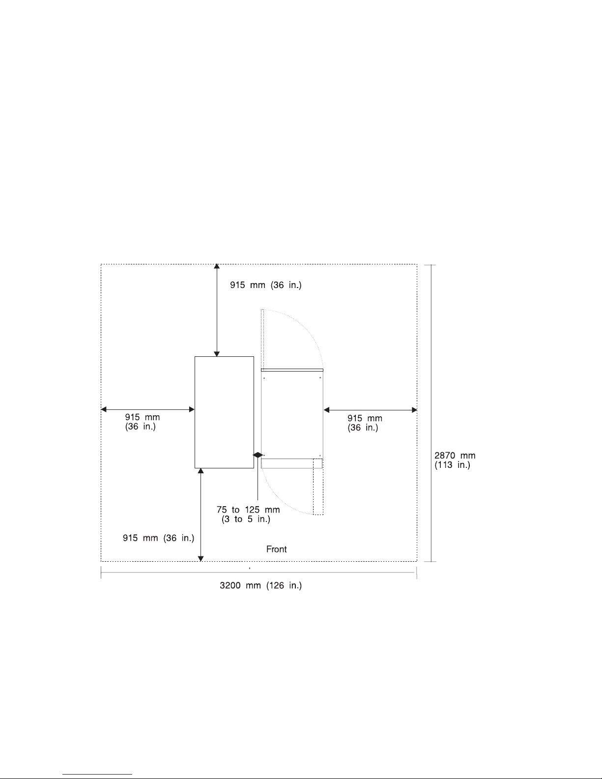
System Service Clearances
The amount of space needed by the units during service is indicated by the dotted line
in the following illustration.
For multiple racks placed side by side, the left and right clearances apply only to the
leftmost and rightmost rack.
Note: If you are planning to install an models S80 and S85 in an RS/6000 SP system
environment, refer to RS/6000 SP Planning Volume 1, Hardware and Physical
Environment, order number GA22-7280, for system-planning information.
Rack Configuration:
Note: Rack units are large and heavy and are not easily moved. Because maintenance
activities require access at both the front and back, allow for extra room. The
footprint in the preceding illustration shows the radius of the swinging doors on
the I/O rack. The minimum space required is indicated on the illustration.
70 Service Guide
Page 93

Noise Emission Notes
1. L
WAd
is the declared sound power emission level for a production series of
machines.
2. L
pAm
is the mean value of the sound pressure emission levels at the operator
position (if any) for a production series of machines.
3. <L
pA>m
is the mean value of the space-averaged sound pressure emission levels at
the one-meter positions for a production series of machines.
4. N/A = Not Applicable (no operator position).
5. All measurements are made in accordance with ISO DIS 779 and reported in
conformance with ISO DIS 7574/4.
External AC Power Cables
To avoid electrical shock, a power cable with a grounded attachment plug is provided.
Use only properly grounded outlets.
Power cables used in the United States and Canada are listed by Underwriter’s
Laboratories (UL) and certified by the Canadian Standards Association (CSA). These
power cords consist of the following:
v Electrical cables, type ST
v Attachment plugs complying with National Electrical Manufacturers Association
(NEMA) L6-30P
v Appliance couplers complying with International Electrotechnical Commission (IEC)
Standard 320, Sheet C13 and C14
Power cables used in other countries consist of the following:
v Electrical cables, Type HD21 or HD22
v Attachment plugs approved by the appropriate testing organization for the specific
countries where they are used
v Appliance couplers complying with the International Electrotechnical Commission
(IEC) Standard 320, Sheet C13 and C14
Refer to “Power Cables” on page 584 for information about replacement power cables.
Chapter 1. Reference Information 71
Page 94

Service Inspection Guide
Perform a service inspection on the system when:
v The system is inspected for a maintenance agreement.
v Service is requested and service has not recently been performed.
v An alterations and attachments review is performed.
v Changes have been made to the equipment that may affect the safe operation of the
equipment.
v External devices with their own power cables have those cables attached.
If the inspection indicates an unacceptable safety condition, the condition must be
corrected before anyone can service the machine.
Note: The correction of any unsafe condition is the responsibility of the owner of the
system.
Perform the following checks:
1. Check the covers for sharp edges and for damage or alterations that expose the
internal parts of the system unit.
2. Check the covers for proper fit to the system unit. They should be in place and
secure.
3. Ensure that the rack stabilizer is installed and securely attached to the rack.
4. Perform the appropriate power-off procedures.
5. Open the covers.
6. Check for alterations or attachments. If there are any, check for obvious safety
hazards such as broken wires, sharp edges, or broken insulation.
7. Check the internal cables for damage.
8. Check for dirt, water, and any other contamination within the system unit.
9. Check the voltage label on the back of the system unit to ensure that it matches
the voltage at the outlet.
10. Check the external power cable for damage.
11. With the external power cable connected to the system unit, check for 0.1 ohm or
less resistance between the ground lug on the external power cable plug and the
metal frame.
12. Perform the following checks on each device that has its own power cables:
a. Check for damage to the power cord.
b. Check for the correct grounded power cable.
c. With the external power cable connected to the device, check for 0.1 ohm or
less resistance between the ground lug on the external power cable and the
metal frame of the device.
13. Close the doors.
14. Perform the appropriate power-on procedures.
72 Service Guide
Page 95

Chapter 2. Introduction to Diagnostics
models S80 and S85 systems use an integrated set of software diagnostic procedures
to facilitate system maintenance. This book, and the Diagnostics Information for Multiple
Bus Systems, are the basis of the diagnostic procedures for models S80 and S85
servers. In particular, chapters 3, 4, 5, and 10 in this book are important for the trained
service representative to understand and use when isolating a failure on the system.
The manufacturer recommends that systems configured with 4GB of memory or greater
have access to a 4mm or 8mm tape drive for submission of system dump information if
required. This function can be accomplished through locally attached or
network-attached devices, as appropriate.
Maintenance Analysis Procedures (MAPs)
Maintenance Analysis Procedures (MAPs) are used to guide the trained service person
through the complex multi-rack models S80 and S85 server. These MAPs are the entry
point for all isolation and error recovery procedures. models S80 and S85 servers use a
set of integrated procedures, to which the MAPS are the primary entry point.
The MAPS are as follows:
v Entry MAP
v Quick Entry MAP
v Problem Determination MAP
v Power MAP
v Minimum Configuration MAP
The Entry Map is the starting point for problem determination. The purpose of this MAP
is to quickly point to the proper MAP or service reference information either in this book,
or in the common book set, which includes the Diagnostic Information for Multiple Bus
Systems and PCI Adapter Placement Reference.
The Quick Entry MAP is a subset of the Entry MAP and helps to save time for certain
problems.
The Problem Determination MAP provides a structured analysis method to get an error
code if one is not provided by the customer, or if diagnostics cannot be loaded.
The Power MAP deals with isolation of components and cables to diagnose a power
problem. Power problems can be related to powering up and down the system
(including the I/O racks), or power failures that occur after power is turned on.
The Minimum Configuration MAP is used to locate defective components not found by
normal diagnostics or error-isolation methods. This MAP provides a systematic method
of isolation to the failing item or items.
© Copyright IBM Corp. 1999, 2000 73
Page 96

Error Codes
models S80 and S85 servers use multiple sets of error codes which are referred to
throughout this book (primarily in Chapters 4, 5 and 6). These codes are a blend of
traditional error codes and codes generated by newly integrated software used in
models S80 and S85 servers. Understanding the definition and relationships of these
codes is important to the service personnel who are installing or maintaining models
S80 and S85 servers.
Codes that can display on the operator panel or in error logs are as follows:
Checkpoints Checkpoints display on the operator panel during the initial program
load (IPL) of the system. Checkpoints indicate the progress of the
IPL.
Error Codes Error codes display on the operator panel if the system firmware
detects an error during IPL or during normal operation.
SRN Service request number (SRN) is usually a 6-digit number
representing a specific failure of a specific item. SRNs are displayed
on the system operator panel.
SRC System reference codes (SRC) are a sequence of codes that are
used to identify status and describe a failure. Failures can result from
hardware, software, or firmware. SRCs display on the system
operator panel. SRCs primarily deal with items pertinent to the system
rack and its associated hardware, software, and firmware.
Displaying and Using SRCs
SRCs automatically display on the system operator panel with operator panel “Function
11.” The four leftmost characters displayed describe the reference code identifier. The
four rightmost characters are the unit reference code. An SRC can consist of up to 36
bytes of information. You can view other words of the SRC by using the increment or
decrement functions on the operator panel.
Functions 11 and 13 through 19 are valid SRC data words. Word 19 provides the CCIN
number which identifies the specific failing memory or processor card in the system
rack. With this information, the service representative can identify the failing FRU and
order the correct part. The SRC types can be identified by the first digit after the 11-3 in
Function 11. The valid reference code identifiers for models S80 and S85 systems are
listed below.
0000 Hardware-reported error. A system problem resulted from a hardware problem.
1XXX Hardware-reported error. A system problem resulted from a hardware problem.
A1XX Attention or action required. The system is waiting for a user action.
B006 Machine check or internal problem detected by firmware. A firmware program
detected either a software or a hardware error.
B1XX Machine check or internal problem detected by firmware. A firmware program
detected either a software or a hardware error.
74 Service Guide
Page 97

B4xx Machine check or internal problem detected by firmware. A firmware program
detected either a software or a hardware error.
C1XX IPL status. Status SRCs indicate the progression of the IPL.
C3XX IPL status. Status SRCs indicate the progression of the IPL.
D1XX General system status. Status SRCs indicate the status of system functions
when the console is not available.
IPL Checkpoints and Error Codes
models S80 and S85 servers provide checkpoints and error codes to display during
system initial program load (IPL). These checkpoints and error codes are unique to
particular instances and to hardware, software, and firmware components of the
system. The sets of checkpoints and error codes are listed below:
v Three-digit SRN of the form 101-xxx
v Eight-digit checkpoint in SRC format of the form C1XX-xxxx
v Eight-digit checkpoint in SRC format of the form C3XX-xxxx
v Four-digit checkpoints of the form E0XX
v Four-digit checkpoints of the form E1XX
v Four-digit checkpoints of the form E4XX
v Four-digit checkpoints of the form E5XX
Checkpoints can become error codes if the system fails to advance past the point at
which the code is presented. SRNs are listed in Diagnostic Information for Multiple Bus
Systems. “Chapter 4. Checkpoints” on page 135 in this book contains a list of the
checkpoints. Each entry provides a description of the event and the recommended
action if the system fails to advance.
FRU Isolation
For a list of error codes and recommended actions for each code, see “Chapter 5. Error
Code to FRU Index” on page 157. These actions can refer to “Chapter 10. Models S80
and S85 Parts” on page 535, “Chapter 3. Maintenance Analysis Procedures (MAPs)” on
page 79, or provide informational message and directions. If a replacement part is
indicated, the part name is included. The respective AIX and physical location codes
are listed per each occurrence as required. Locations codes are listed under “AIX and
Physical Location Code Reference Tables” on page 48.
To determine part numbers and view component diagrams, see “Chapter 10. Models
S80 and S85 Parts” on page 535. The beginning of the chapter provides a parts index
with the predominant field replaceable units (FRUs) listed by name. The remainder of
the chapter provides illustrations of the various assemblies and components that make
up models S80 and S85 systems. System rack components are listed first, then I/O
rack, and then accessories.
Chapter 2. Introduction to Diagnostics 75
Page 98

Electronic Service Agent
Service support for the models S80 and S85 can be enhanced through the use of the
application program, Electronic Service Agent. This application provides a number of
advantages for the models S80 and S85 customer including automatic error reporting
and analysis without customer intervention. The Electronic Service Agent kit is shipped
with the models S80 and S85 server and includes the following:
v Electronic Service Agent program on diskette
v Appropriate modem for remote communication
v Applicable cables
v Electronic Service Agent User’s Guide, for Electronic Service Agent.
See the Electronic Service Agent User’s Guide, for more details on Electronic Service
Agent.
Using the Service Processor and Electronic Service Agent
The service processor and electronic service agent features protect users against
unnecessary system downtime by keeping support personnel (both internal and
external) aware of any unexpected changes in the system environment. In combination,
the two features provide a flexible solution to automated system maintenance.
Service Processor
The service processor runs on its own power boundary and continually monitors
hardware attributes, the AIX operating system, and the environmental conditions within
the system. Any system failure that prevents the system from returning to an
operational state (a fully functional AIX operating system) is reported by the service
processor. The service processor is controlled by firmware and does not require the AIX
operating system to be operational to perform its tasks. If any system failures are
detected, the service processor can take predetermined corrective actions. The
methods of corrective actions are as follows:
v Surveillance
v Call Home
v AIX operating system monitoring
Surveillance is a function in which the service processor monitors the system through
heartbeat communication with the system firmware. The heartbeat is a periodic signal
that the firmware can monitor. During system startup, the firmware surveillance monitor
is automatically enabled to check for heartbeats from the firmware. If a heartbeat is not
detected within a default period, the service processor cycles the system power and
attempts to restart until the system either restarts successfully, or a predetermined retry
threshold is reached. In the event the service processor is unsuccessful in bringing the
system online (or in the event that the user asked to be alerted to any service
processor-assisted restarts), the system can call home to report the error.
The call home function can be initialized to call either a service center telephone
number, a customer administration center, or a digital pager telephone number. The
service processor can be configured to stop at the first successful call to any of the
numbers listed, or can be configured to call every number provided. If connected to the
76 Service Guide
Page 99

service center, the service processor transmits the relevant system information (the
system’s serial number and model type) and service request number (SRN). If
connected to a digital pager service, the service processor inputs a customer voice
telephone number defined by the customer. An established sequence of digits or the
telephone number to a phone near the failed system could be used to signal a system
administrator to a potential system failure.
During normal operations, the service processor can also be configured to monitor the
AIX operating system. If AIX does not respond to the service processor heartbeat, the
service processor assumes the operating system is hung. The service processor can
automatically initiate a restart and, if enabled, initiate the call home function to alert the
appropriate people to the system hang. Enabling operating system surveillance also
affords AIX the means to detect any service processor failures and report those failures
to the electronic service agent application.
Unlike the electronic service agent, the service processor cannot be configured in a
client/server environment where one system can be used to manage all dial-out
functionally for a set of systems.
Prior to installing the service processor feature, ensure that you have the latest levels of
service processor microcode and system firmware. You also need a properly configured
modem. For more information on configuring a modem, see “Modem Configuration
Menu” on page 461.
Electronic Service Agent
The electronic service agent is a software extension to the AIX operating system that
monitors the system while the AIX operating system is running. The electronic service
agent monitors and analyzes all recoverable system failures, and, if needed, can
automatically place a service call to a service center (without user intervention).
The service center receives the machine type/serial number, host name, SRN, and a
problem description. The service center analyzes the problem report and, if warranted,
dispatches a service person to the customer site. The service center also determines if
any hardware components need to be ordered prior to the service person’s arrival.
The electronic service agent code also gives the user the option to establish a single
system as the problem-reporting server. A single system, accessible over the user
network, can be used as the central server for all the other systems on the local area
network (LAN) that are running the electronic service agent application. If the electronic
service agent application on a remote client decides a service request needs to be
placed, the client forwards the information to the electronic service agent server who
dials the service center telephone number from its locally attached modem. In this
scenario, the user only needs to maintain a single analog line for providing call-out
capabilities for a large set of servers.
When used in a scalable parallel (SP) environment, a client/server type implementation
is configured. The electronic service agent client code runs on each of the SP nodes.
The server component runs on the control workstation. In the event of any system
failures, the relevant information is transmitted to the control workstation through the
Chapter 2. Introduction to Diagnostics 77
Page 100

integrated Ethernet. After it is alerted to the system failure, the control workstation
initiates actions to prepare and send the service request.
A modem is required for enabling automated problem-reporting to the IBM service
center. Configuration files for several types of modems are included as part of the
electronic service agent package. Refer to “Modem Configuration Menu” on page 461
for more information on configuring your modem.
78 Service Guide
 Loading...