

Page 1

Enterprise Server S80
pSeries 680 Model S85
Installation Guide
IBM
SA38-0582-00
Page 2

First Edition (November 2000)
Before using this information and the product it supports, read the information in “Safety Notices” on page v,
“Appendix B. Environmental Notices” on page 43, and “Appendix C. Notices” on page 45.
©International Business Machines Corporation 2000. All rights reserved.
Note to U.S. Government Users - Documentation related to restricted rights - Use, duplication, or disclosure is subject
to the restrictions set forth in the GSA ADP Schedule Contract with IBM Corp.
Page 3

Contents
Safety Notices ........................v
Electrical Safety ........................v
Laser Safety Information .....................vi
Data Integrity and Verification ..................vii
About This Book .......................ix
ISO 9000 ..........................ix
Online Publications.......................ix
Related Publications ......................ix
Trademarks .........................x
Chapter 1. System Installation Procedure ..............1
Step 1. Inventory .......................1
Step 2. Observe this Safety Notice During Installation ...........1
Step 3. Check the Customer Environment ...............2
Step 4. Check Customer Outlets ..................3
Step 5. Set Up the System Racks ..................4
Step 6A. Attach the I/O Rack to a Concrete Floor.............7
Attaching the I/O Rack to a Concrete Floor ..............8
Attaching the I/O Rack to a Concrete Floor Beneath a Raised Floor .....10
Step 6B. Attach the System Rack to a Concrete Floor ...........14
Attaching the System Rack to a Concrete Floor .............15
Attaching the System Rack to a Concrete Floor Beneath a Raised Floor.....16
Step 7. Attach the Front Electrical Outlet ...............18
Step 8. Attach the Rear Electrical Outlet ...............22
Step 9. Remove the Shipping Brackets and Install Covers.........26
Step 10. Install the I/O Rack Door Guide ...............27
Step 11. Connect the Operator Panel Cable and the JTAG Cable Between the
Racks ..........................28
Step 12. Connect RIO and SPCN Cables Between the Racks ........28
Step 13. Set Up Attached Devices .................28
Step 14. Update the Device Records ................29
Step 15. Attach External Devices..................29
Step 16. Connect the Power ...................29
Step 17. Power On and Check Out the System .............29
Checklist If Problems Occur ...................29
Step 18. Service Processor Setup and Test ..............30
Step 19. Install the Modem and Electronic Service Agent ..........30
Step 20. Finish the Installation ..................30
Chapter 2. Using the System Verification Procedure ..........33
Chapter 3. Installing Options for Your System ............37
Appendix A. Communications Statements ..............39
Federal Communications Commission (FCC) Statement ..........39
33
33
iii
Page 4

European Union (EU) Statement ..................39
International Electrotechnical Commission (IEC) Statement .........40
United Kingdom Telecommunications Safety Requirements .........40
Avis de conformité aux normes du ministère des Communications du Canada. . . 40
Canadian Department of Communications Compliance Statement .......40
VCCI Statement .......................40
Electromagnetic Interference (EMI) Statement - Taiwan ..........41
Radio Protection for Germany ...................41
Appendix B. Environmental Notices ................43
Product Recycling and Disposal ..................43
Environmental Design .....................43
Unit Emissions ........................43
Appendix C. Notices .....................45
Appendix D. Cabling the System Rack and I/O Rack ..........47
Connecting JTAG and Operator Panel Cables .............48
I/O Rack Rear Locations ....................49
I/O Drawer Locations......................50
10 EIA Unit I/O Drawer Front View ................50
10EIAUnitI/ODrawerRearView................51
10 EIA Unit I/O Drawer System board Locations............53
Service Processor Card Locations ................55
Fan Monitor Control (FMC) Card Locations (10 EIA Unit I/O Drawer) .....56
Power Distribution Board Locations ................56
Connecting RIO and SPCN Cables .................57
Appendix E. System Records ..................63
Record the Identification Numbers .................63
S80 and S85 System Rack...................63
S80 and S85 System Rack Memory Configuration ...........63
S80 and S85 System Rack Cabling Configurations - RIO Cabling ......63
S80 and S85 System Rack Cabling Configurations - SPCN Cabling .....64
Primary I/O Drawer Device Records.................65
Additional I/O Drawer Device Records ................68
Index ...........................71
Reader’s Comments — We’d Like to Hear From You ..........73
iv S80, S85 Installation Guide
Page 5

Safety Notices
A
danger
death or serious personal injury.
A
caution
moderate or minor personal injury.
Electrical Safety
Observe the following safety instructions any time you are connecting or disconnecting
devices attached to the workstation.
DANGER
An electrical outlet that is not correctly wired could place hazardous voltage
on metal parts of the system or the devices that attach to the system. It is the
responsibility of the customer to ensure that the outlet is correctly wired and
grounded to prevent an electrical shock.
Before installing or removing signal cables, ensure that the power cables for
the system unit and all attached devices are unplugged.
When adding or removing any additional devices to or from the system,
ensure that the power cables for those devices are unplugged before the
signal cables are connected. If possible, disconnect all power cables from the
existing system before you add a device.
notice indicates the presence of a hazard that has the potential of causing
notice indicates the presence of a hazard that has the potential of causing
Use one hand, when possible, to connect or disconnect signal cables to
prevent a possible shock from touching two surfaces with different electrical
potentials.
During an electrical storm, do not connect cables for display stations, printers,
telephones, or station protectors for communication lines.
CAUTION:
This product is equipped with a three–wire power cable and plug for the user’s
safety. Use this power cable with a properly grounded electrical outlet to avoid
electrical shock.
DANGER
To prevent electrical shock hazard, disconnect the power cable
CAUTION:
This unit has more than one power supply cord. To reduce the risk of electrical
shock, disconnect two power supply cords before servicing.
v
Page 6
Laser Safety Information
The optical drive in this system unit is a laser product. The optical drive has a label that
identifies its classification. The label, located on the drive, is shown below.
The optical drive in this system unit is certified in the U.S. to conform to the
requirements of the Department of Health and Human Services 21 Code of Federal
Regulations (DHHS 21 CFR) Subchapter J for Class 1 laser products. Elsewhere, the
drive is certified to conform to the requirements of the International Electrotechnical
Commission (IEC) 825 (1st edition 1984) and CENELEC EN 60 825:1991 for Class 1
laser products.
CAUTION:
A class 3 laser is contained in the device. Do not attempt to operate the drive
while it is disassembled. Do not attempt to open the covers of the drive as it is
not serviceable and is to be replaced as a unit.
CLASS 1 LASER PRODUCT
LASER KLASSE 1
LUOKAN 1 LASERLAITE
APPAREIL A LASER DE CLASSE 1
IEC 825:1984 CENELEC EN 60 825:1991
Class 1 laser products are not considered to be hazardous. The optical drive contains
internally a Class 3B gallium-arsenide laser that is nominally 30 milliwatts at 830
nanometers. The design incorporates a combination of enclosures, electronics, and
redundant interlocks such that there is no exposure to laser radiation above a Class 1
level during normal operation, user maintenance, or servicing conditions.
vi S80, S85 Installation Guide
Page 7

Data Integrity and Verification
IBM computer systems contain mechanisms designed to reduce the possibility of
undetected data corruption or loss. This risk, however, cannot be eliminated. Users who
experience unplanned outages, system failures, power fluctuations or outages, or
component failures must verify the accuracy of operations performed and data saved or
transmitted by the system at or near the time of the outage or failure. In addition, users
must establish procedures to ensure that there is independent data verification before
relying on such data in sensitive or critical operations. Users should periodically check
the IBM support websites for updated information and fixes applicable to the system and
related software.
vii
Page 8

viii S80, S85 Installation Guide
Page 9

About This Book
This book provides information on how to setup and install the system, use diagnostics,
use service aids, and verify system operation. This book also provides information to
help you solve some of the simpler problems that might occur.
ISO 9000
ISO 9000 registered quality systems were used in the development and manufacturing
of this product.
Online Publications
RS/6000 publications are available online. To access the online books, visit our Web
site at: http://www.rs6000.ibm.com/resource/hardware_docs/
Related Publications
The following publications are available:
v The
SA38-0560, contains reference information, maintenance analysis procedures
(MAPs), error codes, removal and replacement procedures, and a parts catalog.
v The
contains diagnostic information, service request numbers (SRNs), and failing function
codes (FFCs).
v The
Systems,
and cables for your system. This manual is intended to supplement the service
information found in the
v The
specifications to help you do space and environmental planning before your system
is installed.
v The
information about slot requirements for installing PCI adapters. This book is intended
to be used to help plan and install PCI adapters for maximum performance from your
system.
v
SSA Adapters User’s Guide and Maintenance Information
is intended to help users and service representatives work with and diagnose
problems with SSA adapters and devices.
v The
Scalability Installation and Administration Guide
for HACMP/ES planning information.
v The
order number SC23-4277, is needed for HACMP/ES planning information.
Enterprise Server S80, p Series 680 Model S85 Service Guide
Diagnostic Information for Multiple Bus Systems
IBM RS/6000 Adapters, Devices, and Cable Information for Multiple Bus
order number SA38-0516 contains information about adapters, devices,
Diagnostic Information for Multiple Bus Systems
Site and Hardware Planning Information
PCI Adapter Placement Reference
High Availability Cluster Multi-Processing for AIX, Version 4.3: Enhanced
High Availability Cluster Multi-Processing for AIX, Version 4.3: Planning Guide
, order number SA38-0508, contains
, order number SA38-0538, contains
, order number SA38-0509,
, order number SA33-3272,
, order number SC23-4284, is needed
, order number
.
,
ix
Page 10

Trademarks
v The
7133 SSA Disk System: Operator Guide
to operate the 7133 SSA Disk System and how to install or replace disk drives to the
system, and how to deal with problems encountered when using the system.
v The
7133 SSA Disk Subsystem: Service Guide
the service technician to repair system failures in the 7133 SSA Disk System.
The following trademarks apply to this information:
v AIX is a registered trademark of the International Business Machines Corporation.
v IBM is a registered trademark of the International Business Machines Corporation.
v Velcro is a trademark of Velcro Industries.
, order number xxxxxxx, describes how
, order number xxxxxxx, is used by
x S80, S85 Installation Guide
Page 11

Chapter 1. System Installation Procedure
Follow the procedures in this chapter to install the Enterprise Server S80 and the p
Series 680 Model S85. The estimated installation time for the system is:
Install Activity 3.5 Hours
Planning Activity 2.0 Hours
________________ _________
Total Time 5.5 Hours
Step 1. Inventory
v The
About Your Machine
carton. Check the listing to verify that you have all the items that were shipped with
the system.
v AIX operating system publications
v Enterprise Server S80, p Series 680 Model S85 User’s Guide, order number
SA38-0557
v Enterprise Server S80, p Series 680 Model S85 Service Guide, SA38-0560
v Enterprise Server S80, p Series 680 Model S85 Installation Guide, order number
SA38-0582 (this book)
v
Diagnostic Information for Multiple Bus Systems
IBM RS/6000 Adapters, Devices, and Cable Information for Multiple Bus Systems,
v
order number SA38-0516
PCI Adapter Placement Reference
v
v System Unit Safety Information, order number SA23-2652
Electronic Service Agent for RS/6000 User’s Guide
v
v Support Information and Warranty.
listing is in a plastic bag attached to the outside of the
, order number SA38-0538.
, order number SA38-0509
, order number ZA38-0383
Verify with the customer that the following items are available. You will need them to
complete this installation.
1. A floor plan, showing where to place each rack.
2. A console, including cables and a power source.
3. A modem for the electronic customer-support function (if the customer ordered this
function). This includes the correct telephone jack, cables, and a power source.
Step 2. Observe this Safety Notice During Installation
Note: For a translation of this notice, see the
System Unit Safety Information
manual.
1
Page 12

DANGER
An electrical outlet that is not correctly wired could place hazardous voltage
on metal parts of the system or the devices that attach to the system. It is the
responsibility of the customer to ensure that the outlet is correctly wired and
grounded to prevent an electrical shock.
Before installing or removing signal cables, ensure that the power cables for
the system unit and all attached devices are unplugged.
When adding or removing any additional devices to or from the system,
ensure that the power cables for those devices are unplugged before the
signal cables are connected. If possible, disconnect all power cables from the
existing system before you add a device.
Use one hand, when possible, to connect or disconnect signal cables to
prevent a possible shock from touching two surfaces with different electrical
potentials.
During an electrical storm, do not connect cables for display stations, printers,
telephones, or station protectors for communication lines.
CAUTION:
This product is equipped with a three–wire power cable and plug for the user’s
safety. Use this power cable with a properly grounded electrical outlet to avoid
electrical shock.
CAUTION:
This unit has more than one power supply cord. To reduce the risk of electrical
shock, disconnect two power supply cords before servicing.
CAUTION:
Energy hazard, remove power before servicing. Disconnect two power supply
cords.
Step 3. Check the Customer Environment
1. Verify with your Installation Planning Representative or the customer that any
station-protector boxes used are correctly installed according to the Site and
Hardware Planning Information manual.
2. Make sure the customer is aware that the recommended temperature for IBM
products is 24° C (75° F) and the recommended relative humidity is 45%. The
acceptable operating temperature range is 10° C (50° F) to 38° C (100° F), and the
acceptable operating humidity range is 8% to 80%.
3. Make sure the customer is aware that the front and rear service clearances around
the system rack and I/O rack should be 36 inches (900mm). The service clearances
are important for proper air circulation, weight distribution, and the safety of both the
service representative and the customer.
2 S80, S85 Installation Guide
Page 13

Refer to ″Specifications″ in the Enterprise Server S80 p Series 680 Model S85
Service Guide, order number SA38-0560, for more planning information.
Step 4. Check Customer Outlets
Note: For a translation of this notice, see the
order number SA23-2652.
CAUTION:
Do not touch the receptacle or the receptacle faceplate with anything other than
your test probes before you have met the requirements in Step 8 below.
__ 1. Have the customer locate and turn off the branch circuit CB (circuit breaker).
Attach tag S229-0237, which reads “Do Not Operate.”
Note: All measurements are made with the receptacle faceplate in the normal
installed position.
__ 2. Some receptacles are enclosed in metal housings. On receptacles of this type,
perform the following steps:
a. Check for less than 1 volt from the receptacle case to any grounded metal
structure in the building, such as a raised-floor metal structure, water pipe,
building steel, or similar structure.
b. Check for less than 1 volt from receptacle ground pin to a grounded point in
the building.
Note: If the receptacle case or faceplate is painted, be sure the probe tip
penetrates the paint and makes good electrical contact with the metal.
__ 3. Check the resistance from the ground pin of the receptacle to the receptacle
case. Check resistance from the ground pin to building ground. The reading
should be less than 1.0 ohm, which indicates the presence of a continuous
grounding conductor.
__ 4. If any of the three checks made in substeps 2 and 3 are not correct, ask the
customer to remove the power from the branch circuit and make the wiring
corrections; then check the receptacle again.
System Unit Safety Information
manual,
Note: Do not use the digital multimeter to measure grounding resistance.
__ 5. Check for infinite resistance between the phase pins. This is a check for a wiring
short.
Note: For a translation of this notice, see the
manual, order number SA23-2652.
CAUTION:
If the reading is other than infinity, do not proceed! Have the customer
make necessary wiring corrections before continuing. Do not turn on the
branch circuit CB until all the above steps are satisfactorily completed.
System Unit Safety Information
Chapter 1. System Installation Procedure 3
Page 14
__ 6. Have the customer turn on the branch circuit CB. Measure for appropriate
voltages between phases. If no voltage is present on the receptacle case or
grounded pin, the receptacle is safe to touch.
__ 7. With an appropriate meter, verify that the voltage at the outlet is correct.
__ 8. Verify that the grounding impedance is correct by using the ECOS 1020, 1023,
B7106, or an appropriately approved ground impedance tester.
Note: Do
not
use the 120-volt convenience outlets inside a machine to power
the tester.
Step 5. Set Up the System Racks
Note: For a translation of this notice, see the
CAUTION:
The stabilizer must be firmly attached to the bottom of the I/O rack to prevent the
rack from turning over when the drawers are pulled out of the rack. Do not pull
out or install any drawer or feature if the stabilizer is not attached to the rack.
Shipping material must be removed, and the system rack and I/O rack and place them
where they are to be installed before installation can begin. If this has not been done,
consult the customer and the marketing representative as necessary.
1. Remove all packing and tape, if present, from the system rack and the I/O rack.
2. Position the racks according to the customer floor plan.
Note: As viewed from the front, position the primary I/O rack (the primary I/O rack
contains the service processor) on the right side of the system rack. A
clearance of 10 cm (4 inches) between the racks is required to allow access
to the I/O rack door.
If you are attaching the racks to a concrete floor or a raised floor, refer to
“Step 6A. Attach the I/O Rack to a Concrete Floor” on page 7, and then
return here.
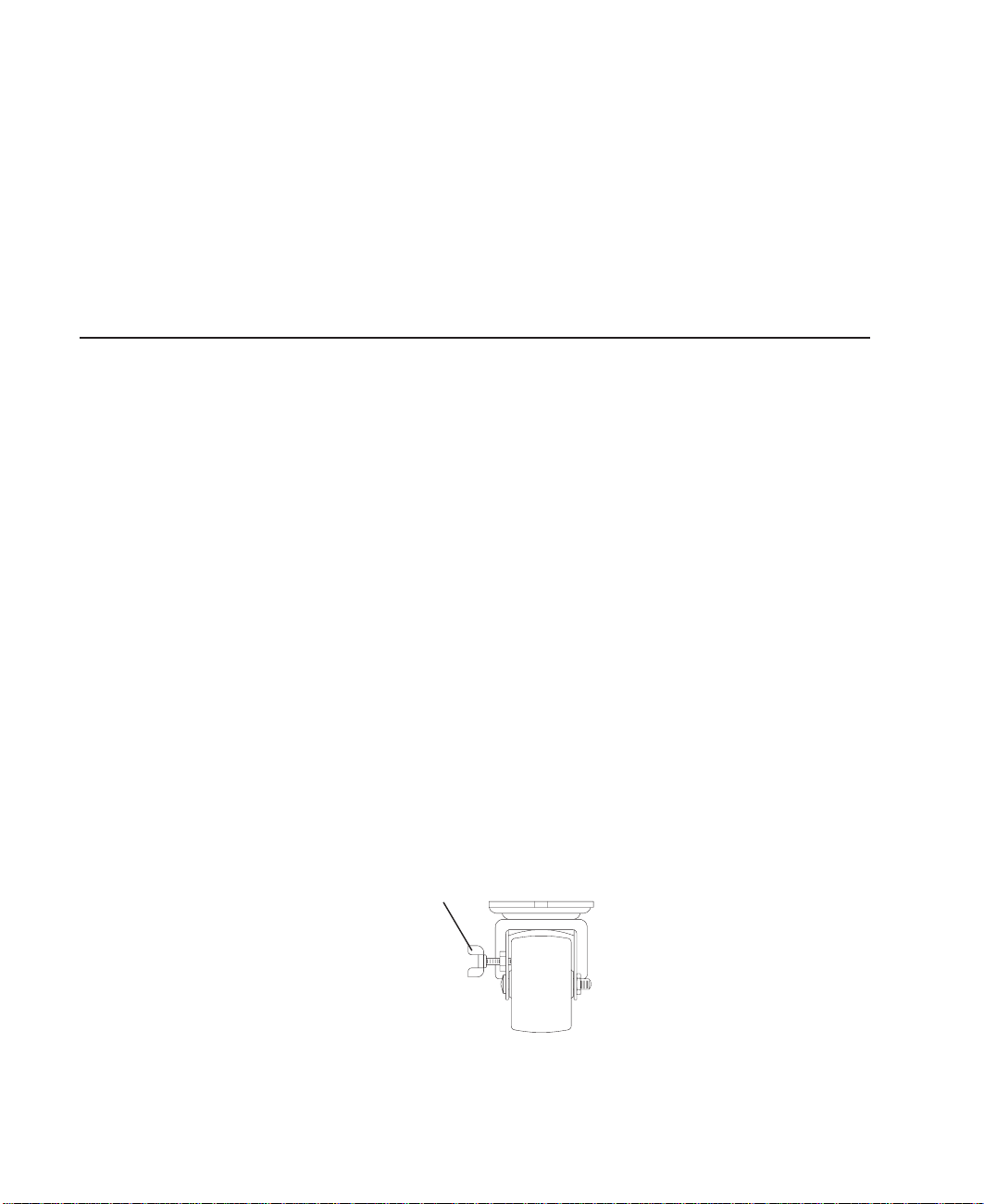
3. On both racks, lock each caster wheel by tightening the thumbscrew on the caster.
System Unit Safety Information
manual.
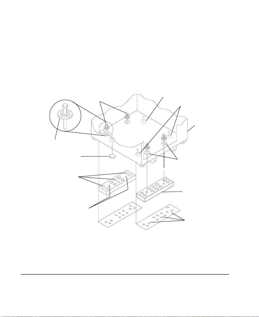
4. Adjust the leveling feet on the I/O rack by doing the following:
a. Loosen the locking nut by turning the locking nut counter-clockwise (away from
the bottom of the rack).
4 S80, S85 Installation Guide
Thumbscrew
Page 15
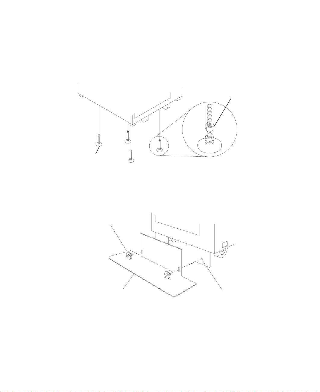
b. Adjust the height of the leveling feet by rotating the leveling feet either upward
or downward according to the level of the surface on which the rack is placed.
Repeat this for the remaining leveling feet as needed.
c. When the rack is leveled, tighten the locking nuts on all of the leveling feet.
Locking Nut
Leveling Feet (4)
5. Align the slots in the stabilizer with the mounting holes in the bottom front of the
I/O rack.
6. Ensure that the base of the stabilizer rests firmly on the floor.
7. Install the two mounting screws and hand-tighten.
Mounting Screw
Stabilizer
8. Use the crank supplied with the system unit to alternately tighten the mounting
screws until they are firmly seated.
Mounting Hole
Chapter 1. System Installation Procedure 5
Page 16
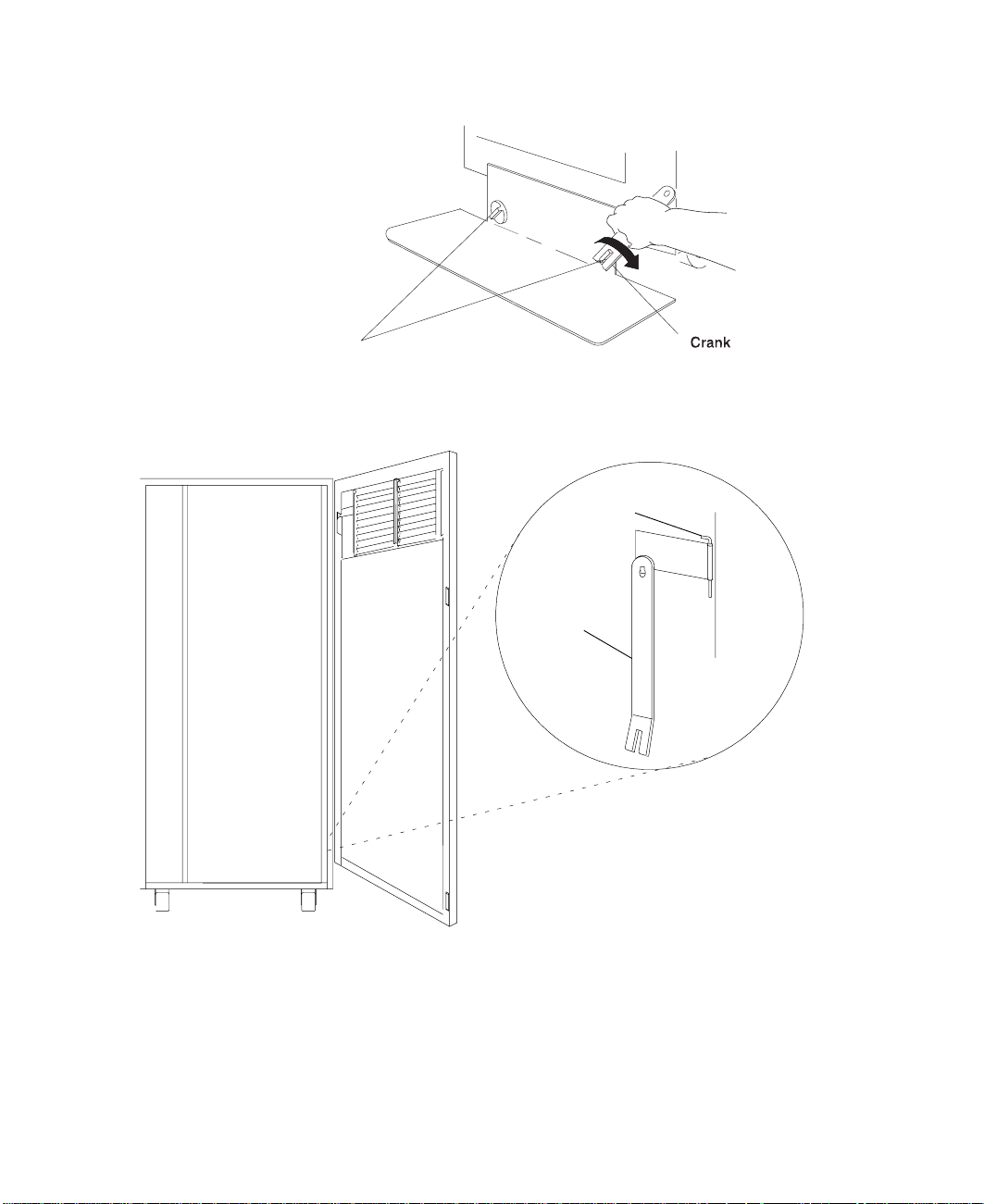
Mounting Screw
9. Hang the crank and tightening rod on the bracket near the bottom of the right wall
inside the back of the rack.
Tightening
Rod
Crank
10. Install the rear stabilizer on the I/O rack, as follows:
a. Loosen the lower screws on the stabilizer assembly.
b. Slide the stabilizer assembly onto the bottom of the rack.
c. Install screws at the top of the stabilizer assembly and tighten.
d. Tighten the lower screws on the stabilizer assembly.
6 S80, S85 Installation Guide
Page 17
e. Adjust the bolts to the floor to ensure that the stabilizer is level and does not
move.
11. If head protectors are installed, remove them from diskette drives.
Step 6A. Attach the I/O Rack to a Concrete Floor
Perform this step if the I/O rack is to be attached to a concrete floor or a concrete floor
beneath a raised floor.
Notes:
1. Ensure that the primary I/O rack (the primary I/O rack contains the service
processor) is positioned on the right side of the system rack when viewed from the
front. A clearance of 10 cm (4 inches) between the racks is required to allow access
to the I/O rack door.
2. If you are attaching the I/O rack:
Chapter 1. System Installation Procedure 7
Page 18

v To a concrete floor, continue with “Attaching the I/O Rack to a Concrete Floor”.
v To a concrete floor below a raised floor, go to “Attaching the I/O Rack to a
Concrete Floor Beneath a Raised Floor” on page 10.
If you are not attaching the I/O rack to a concrete floor, continue with “Step 7. Attach
the Front Electrical Outlet” on page 18.
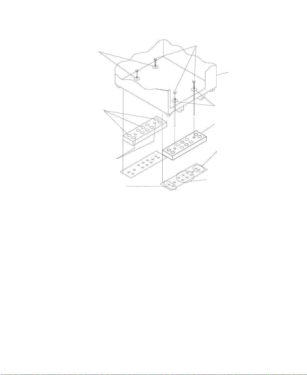
Attaching the I/O Rack to a Concrete Floor
The customer is responsible for attaching the rack-mounting plates to the concrete floor.
Note: Because of the length of the four rack-mounting bolts, the drawer located in the
bottom position of the rack
bolts to the floor.
1. Mark the floor around the edge of each leveling foot.
2. Place the two mounting plates in the approximate mounting locations under the
rack.
3. To align the rack over the mounting plates, do the following:
a. Place the four rack-mounting bolts through the mounting holes at the bottom of
the rack.
b. Position the mounting plates under the four rack-mounting bolts so that the
mounting bolts are centered directly over the tapped holes. Insert the
rack-mounting bolts three or four rotations into the tapped holes.
4. Mark the floor around the edge of both mounting plates.
5. Remove the mounting bolts from the threaded holes.
6. To access the holes in the mounting plates, raise the four leveling feet, and then
move the rack away from the mounting plates.
7. Mark the floor at the center of each hole in the mounting plates (including the
tapped holes).
8. Remove the two mounting plates from the marked locations.
9. At the marked location of the tapped mounting holes, drill two holes approximately
1 inch to allow clearance for the ends of the two rack-mounting bolts. The ends of
the rack-mounting bolts may protrude past the thickness of the mounting plate.
must
be removed to install the four rack-mounting
Note: A minimum of three anchor bolts for each mounting plate must be used to
8 S80, S85 Installation Guide
mount the plates to the concrete floor. Because some of the drilled holes
may be aligned with concrete reinforcement rods below the surface of the
concrete floor, some of the drilled holes may not be usable. For each
mounting plate, select at least three usable holes, two that are on opposite
sides and opposite ends of each other, and one hole at the center.
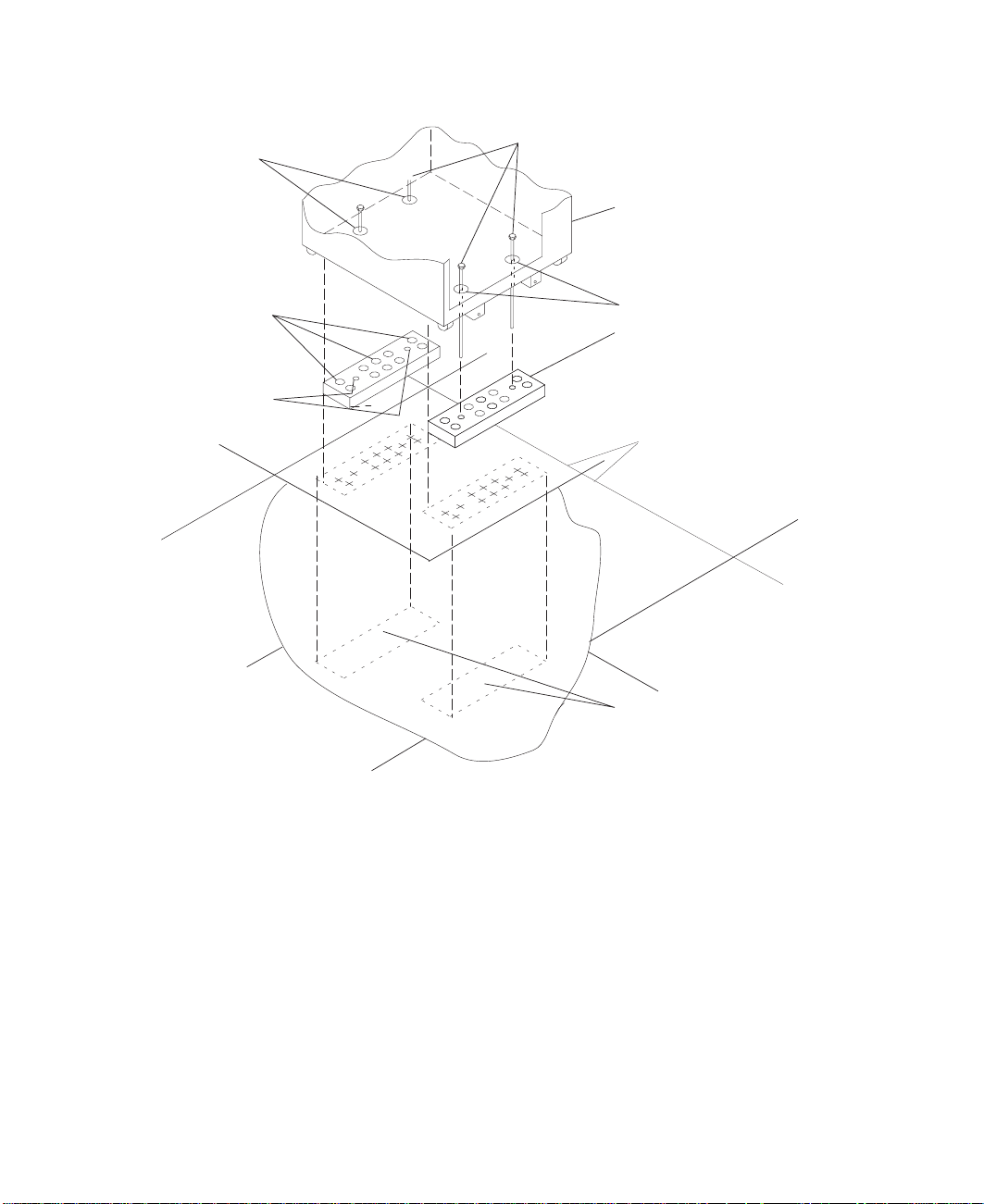
Page 19
Mounting Holes
Rack Mounting Bolts
Front of
Rack
Holes for Anchor
Bolts (10)
Tapped Holes for
Rack Mounting Bolts
Location Marks (Drill One
of These Two Marks)
10. Drill one hole in each group of anchor bolt location marks as indicated on the
marked floor.
11. Using at least three anchor bolts for each mounting plate, mount the two mounting
plates to the concrete floor.
12. Using the location marks for leveling feet as a guide, reposition the rack over the
mounting plates.
13. Place the four rack-mounting bolts through the four metal washers, and then
through the four plastic isolator washers. The flat side of the plastic isolator washer
must be facing upward.
14. To further align the rack over the mounting plates, do the following:
a. Place the four rack-mounting bolts (with the four plastic isolator washers)
through the mounting holes in the bottom of the rack.
b. Align the four mounting bolts to the location of the four tapped holes in the two
mounting plates.
c. Insert the rack-mounting bolts three to four rotations into the tapped holes.
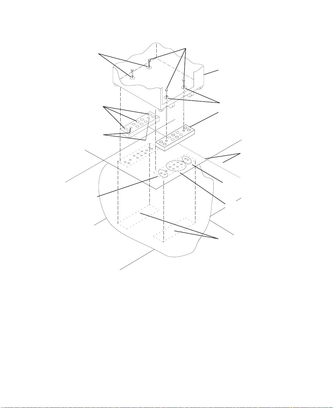
Mounting Holes
Mounting Plate (2)
Location Marks
(Drill One of
TheseTwo Marks)
Location Marks (Drill
One of These Six Marks)
Note: The bottom of the four leveling feet must be positioned over the four
plastic isolator pads when the rack is leveled.
If you are installing an ac-powered rack, do not use the four plastic
isolator pads.
Chapter 1. System Installation Procedure 9
Page 20

15. Place the four plastic isolator pads under the four leveling feet, and then level the
16. Tighten the locking nuts on the leveling feet.
Plastic Isolator
Washer (4)
Plastic Isolator
Pad (4)
Holes for
Anchor Bolts
rack using the four adjustable leveling feet.
Rack-Mounting
Bolts
Leveling Foot (4)
Rack-Mounting
Bolts
Front of
Rack
Mounting
Holes
Mounting
Plates (2)
Tapped Holes for
Rack Mounting Bolts
Location
Marks
17. Tighten the four rack-mounting bolts into the two mounting plates.
18. If a drawer was removed from the bottom position of the rack, reinstall it.
Attaching the I/O Rack to a Concrete Floor Beneath a Raised Floor
The customer is responsible for obtaining the services of a mechanical contractor to
attach the rack-mounting plates on the raised floor with hardware that goes through the
raised floor into the concrete floor below the raised floor. The mechanical contractor
should determine that the raised floor support and the hardware used to attach the rack
mounting plates is sufficient to meet the customer’s requirements for the installation.
Note: Because of the length of the four rack-mounting bolts, the drawer located in the
bottom position of the rack
bolts to the floor.
1. Mark the floor around the edge of each leveling foot.
10 S80, S85 Installation Guide
must
be removed to install the four rack-mounting
Page 21

2. Place the two mounting plates in the approximate mounting locations under the
rack.
3. To align the rack over the mounting plates, do the following:
a. Place the four rack-mounting bolts through the mounting holes at the bottom of
the rack.
b. Position the mounting plates under the four rack-mounting bolts so that the
mounting bolts are centered directly over the tapped holes. Insert the
rack-mounting bolts three or four rotations into the tapped holes.
4. Mark the raised-floor panel around the edge of both mounting plates.
5. Remove the mounting bolts from the threaded holes.
6. To access the holes in the mounting plates, raise the four leveling feet, and then
move the rack away from the mounting plates.
7. Mark the raised-floor panel at the center of each hole in the mounting plates
(including the tapped holes).
8. Remove the two mounting plates from the marked locations.
Chapter 1. System Installation Procedure 11
Page 22
Mounting Holes
Rack Mounting Bolts
Front of
Rack
Holes for Anchor
Bolts (10)
Tapped Holes for
Rack Mounting Bolts
9. At the marked location of the tapped mounting holes, drill two holes approximately
1 inch to allow clearance for the ends of the two rack-mounting bolts. The ends of
the rack-mounting bolts may protrude past the thickness of the mounting plate.
Mounting Holes
Mounting Plate (2)
Raised
Floor Panels
Projection of Mounting
Plates onto Concrete Floor
Note: A minimum of three anchor bolts for each mounting plate must be used to
10. Drill one hole in each group of anchor bolt location marks as indicated on the
marked raised floor panel.
11. Ensure that the marks for the holes for the anchor bolts in the concrete floor align
with the holes in the raised floor panel.
12. Drill the holes in the concrete floor for the anchor bolts.
12 S80, S85 Installation Guide
mount the plates to the raised-floor panel. For each mounting plate, select
at least three usable holes, two that are on opposite sides and opposite
ends of each other, and one hole at the center.
Page 23
Mounting Holes
Rack Mounting Bolts
Front of
Rack
Holes for Anchor
Bolts (10)
Tapped Holes for
Rack Mounting Bolts
Location Marks
(Drill One of
These Two Marks)
13. Place the two mounting plates on the locations indicated on the marked
raised-floor panel.
14. Using at least three anchor bolts for each mounting plate, mount the two mounting
plates through the raised-floor panel to the concrete floor.
15. Using the location marks for leveling feet as a guide, reposition the rack over the
mounting plates.
16. Place the four rack-mounting bolts through the four metal washers, and then
through the four plastic isolator washers. The flat side of the plastic isolator washer
must be facing upward.
17. To further align the rack over the mounting plates, do the following:
a. Place the four rack-mounting bolts (with the four plastic isolator washers)
b. Align the four mounting bolts to the location of the four tapped holes in the two
Mounting Holes
Mounting Plate (2)
Raised
Floor Panels
Location Marks
(Drill One of
These Two Marks)
Location Marks
(Drill One of
These Six Marks)
Projection of Mounting
Plates onto Concrete Floor
through the mounting holes in the bottom of the rack.
mounting plates.
Chapter 1. System Installation Procedure 13
Page 24
18. Place the four plastic isolator pads under the four leveling feet, and then level the
19. Tighten the locking nuts on the leveling feet.
Plastic Isolator
Washer (4)
Plastic Isolator
Pad (4)
c. Insert the rack-mounting bolts three to four rotations into the tapped holes.
Note: The bottoms of the four leveling feet must be positioned over the four
plastic isolator pads when the rack is leveled. If you are installing an AC
powered rack, do not use the four plastic isolator pads.
rack using the four adjustable leveling feet.
Leveling Foot (4)
Rack-Mounting
Bolts
Rack-Mounting
Bolts
Front of
Rack
Mounting
Holes
Holes for
Anchor Bolts
Tapped Holes for
Rack Mounting Bolts
20. Tighten the four rack-mounting bolts into the two mounting plates.
21. If you are attaching an electrical outlet and mounting plate, skip to “Step 7. Attach
the Front Electrical Outlet” on page 18 or “Step 8. Attach the Rear Electrical Outlet”
on page 22 as appropriate, then return here.
22. If a drawer was removed from the bottom position of the rack, reinstall it.
Step 6B. Attach the System Rack to a Concrete Floor
Perform this step if the system rack is to be attached to a concrete floor or a concrete
floor beneath a raised floor.
14 S80, S85 Installation Guide
Mounting
Plates (2)
Location
Marks
Page 25

Notes:
1. Ensure that the primary I/O rack (the primary I/O rack contains the service
processor) is positioned on the right side of the system rack when viewed from the
front. A clearance of 10 cm (4 inches) between the racks is required to allow access
to the I/O rack door.
2. If you are attaching the system rack:
v To a concrete floor, continue with “Attaching the System Rack to a Concrete
Floor”.
v To a concrete floor below a raised floor, go to “Attaching the System Rack to a
Concrete Floor Beneath a Raised Floor” on page 16.
If you are not attaching the system rack to a concrete floor, continue with “Step 7.
Attach the Front Electrical Outlet” on page 18.
Attaching the System Rack to a Concrete Floor
The customer is responsible for attaching the rack-mounting plates to the concrete floor.
1. Install the 4 plate assemblies with the leveling feet, bushings and washers. Make
sure that the leveling feet are backed off the floor level to allow space for the
mounting plates.
2. Place the mounting plates, front and rear, (note that they are different) in the
approximate mounting position under the system rack.
3. To align the system rack over the mounting plate, do the following:
a. Place the four rack-mounting bolts through the plate assembly holes at the
bottom of the rack (install the bushings and washers to ensure bolt
positioning).
Chapter 1. System Installation Procedure 15
Page 26

b. Position the mounting plates under the four rack-mounting bolts so that the
mounting bolts are centered directly over the tapped holes.
c. Insert the rack-mounting bolts three or four rotations into the tapped holes.
4. Mark the floor around the edge of the mounting plates.
5. Remove the mounting bolts from the threaded holes.
6. Move the rack away from the mounting plates.
7. Mark the floor at the center of each hole in the mounting plate (including tapped
holes).
8. Remove the mounting plates from the marked locations.
9. At the marked location of the tapped mounting holes, drill two holes approximately
1 inch to allow clearance for the ends of the two rack-mounting bolts. The ends of
the rack-mounting bolts may protrude past the thickness of the mounting plate.
Note: A minimum of three anchor bolts for each mounting plate must be used to
mount the plates to the concrete floor. Because some of the drilled holes
may be aligned with concrete reinforcement rods below the surface of the
concrete floor, some of the drilled holes may not be usable. For each
mounting plate, select at least three usable holes, two that are on opposite
sides and opposite ends of each other, and one hole at the center.
Drill one hole in each group of anchor bolt location marks as indicated on the
marked floor.
10. Using at least three bolts for each mounting plate, mount the mounting plates to
the concrete floor.
11. Reposition the system rack over the mounting plates.
12. Place the four rack-mounting bolts through the plate assemblies with the D-washer
positioned so that the straight side of the washer is facing inward toward the
system rack.
13. Place the isolator bushing inside the leveling foot with a washer between the
isolator bushing and the floor plate.
14. Insert the rack-mounting bolts three or four rotations into the tapped holes.
15. Turn the leveling foot of the plate assembly down until it contacts the mounting
plate, and then level the rack using the four leveling feet.
16. Lock the leveling feet by tightening the lock nut.
17. Tighten the four rack-mounting bolts into the mounting plates.
Attaching the System Rack to a Concrete Floor Beneath a Raised Floor
The customer is responsible for obtaining the services of a mechanical contractor to
attach the rack-mounting plates on the raised floor with hardware that goes through the
raised floor into the concrete floor below the raised floor. The mechanical contractor
should determine that the raised floor support and the hardware used to attach the rack
mounting plates is sufficient to meet the customer’s requirements for the installation.
16 S80, S85 Installation Guide
Page 27

1. Install the 4 plate assemblies with the levelling feet, bushings, and washers. Make
sure that the leveling feet are backed off the floor level to allow space for the
mounting plates.
2. Place the mounting plates, front and rear, (note that they are different) in the
approximate mounting position under the system rack.
3. To align the system rack over the mounting plate, do the following:
a. Place the four rack-mounting bolts through the plate assembly holes at the
bottom of the rack (install the bushings and washers to ensure bolt
positioning).
b. Position the mounting plates under the four rack-mounting bolts so that the
mounting bolts are centered directly over the tapped holes.
c. Insert the rack-mounting bolts three or four rotations into the tapped holes.
4. Mark the raised-floor panel around the edge of both mounting plates.
5. Remove the mounting bolts from the threaded holes.
6. Move the rack away from the mounting plates.
7. Mark the raised floor at the center of each hole in the mounting plates (including
the tapped holes).
8. Remove the two mounting plates from the marked locations.
9. At the marked location of the tapped mounting holes, drill two holes approximately
1 inch to allow clearance for the ends of the two rack-mounting bolts. Tthe ends of
the rack-mounting bolts may protrude past the thickness of the mounting plate.
Note: A minimum of three anchor plates for each mounting plate must be used to
mount the plates to the concrete floor. Because some of the drilled holes
may be aligned with concrete reinforcement rods below the surface of the
Chapter 1. System Installation Procedure 17
Page 28

concrete floor, some of the drilled holes may not be usable. For each
mounting plate, select at least three usable holes, two that are on opposite
sides and opposite ends of each other, and one hole at the center.
10. Drill one hole in each group of anchor bolt location marks as indicated on the
marked raised-floor panel.
11. Project the holes now in the raised-floor panel down to the concrete floor below.
Ensure that the marks for the holes for the anchor bolts in the concrete floor align
with the holes in the raised floor panel.
12. Drill the holes in the concrete floor for the anchor bolts.
13. Place the mounting plates on the locations on the marked raised-floor panel.
14. Using the three anchor bolts for each mounting plate, mount the two mounting
plates through the raised-floor panel to the concrete floor.
15. Reposition the system rack over the mounting plates.
16. Place the four rack-mounting bolts through the plate assemblies with the D-washer
positioned so that the straight side of the washer is facing inward toward the
system rack.
17. Place the isolator bushing inside the leveling foot with a washer between the
isolator bushing and the floor plate.
18. Insert the rack-mounting bolts three or four rotations into the tapped holes.
19. Turn the leveling foot of the plate assembly down until it contacts the mounting
plate, and then level the rack using the four leveling feet.
20. Lock the leveling feet by tightening the lock nut.
21. Tighten the 4 rack-mounting bolts into the mounting plates.
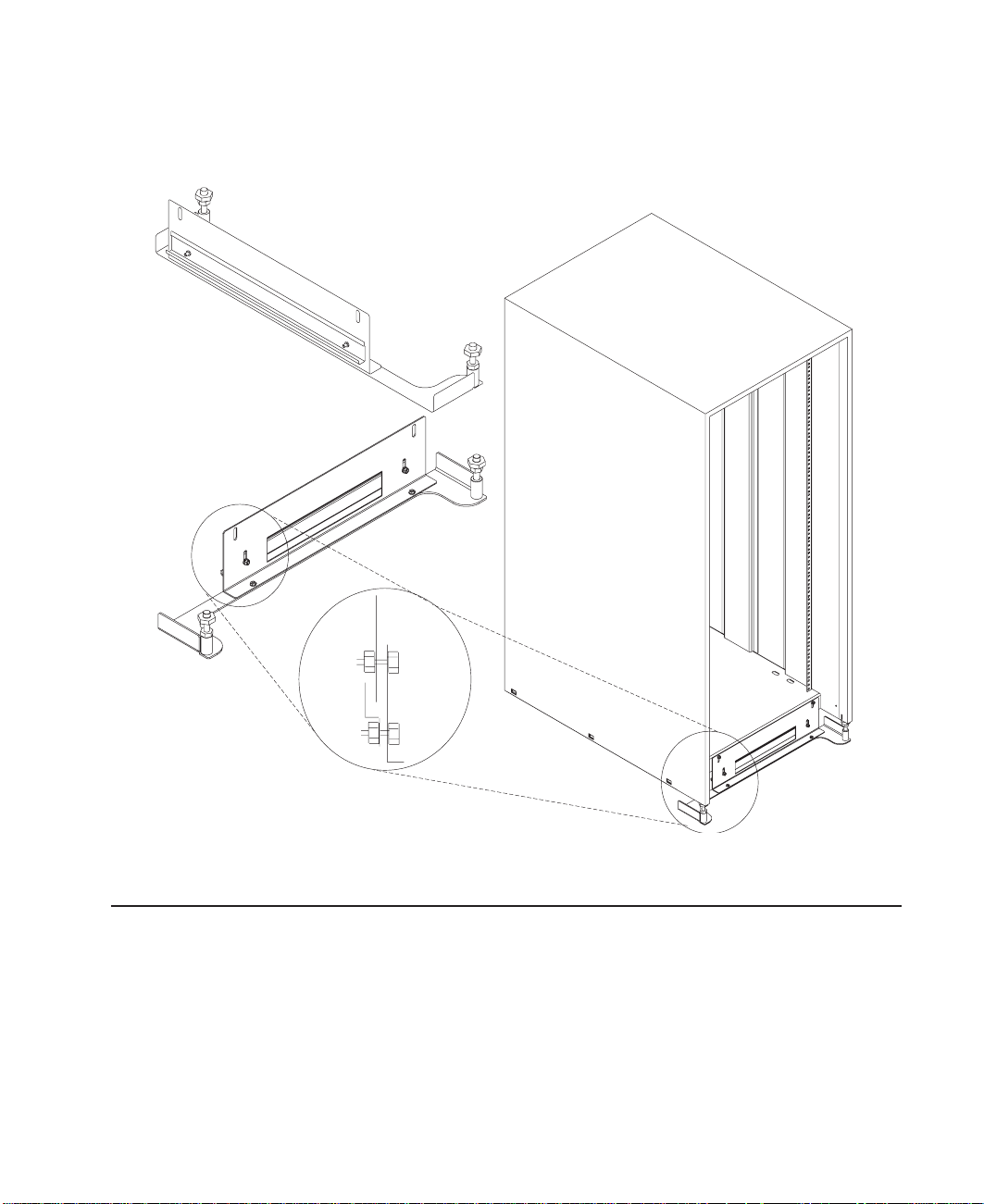
Step 7. Attach the Front Electrical Outlet
Attention: Refer to “Safety Notices” on page v before continuing.
Note: If the rack is on a raised floor without being attached to the concrete floor below
the raised floor, a stabilizer must be installed instead of the front-electrical-outlet
mounting plate. The front-electrical-outlet mounting plate cannot be installed on
the rack when a stabilizer is installed.
1. After the customer has connected the power cable from the customer power source
to the electrical outlet assembly, mount the electrical outlet assembly to the
mounting plate using the two mounting screws (provided by the customer).
18 S80, S85 Installation Guide
Page 29

Power Cable From
Power Source
Mounting Plate
Front of Rack
Electrical Outlet
Assembly
Mounting Screws
2. Place the ground-cable lug through the mounting hole of the mounting plate.
3. Connect the long end of the ground cable to the threaded side of the ground-cable
lug (inside mounting plate), and then install and tighten the ground-lug nut.
Note: The two remaining connections of the ground cable are done in “Step 8.
Attach the Rear Electrical Outlet” on page 22.
Chapter 1. System Installation Procedure 19
Page 30

Front of Rack
Long End of
Ground Cable
Ground Lug Nut
Mounting
Hole
Mounting
Plate
Y-End of
Ground Cable
4. Find the crank (for installing the mounting screws) located inside the rear of the rack
near the bottom of the right wall.
Ground Lug
Long End of Ground
Cable
Ground Connector
(Short End of
Ground Cable)
20 S80, S85 Installation Guide
Page 31

Crank
5. Align the holes of the mounting plate with the holes on the rack, and then install the
two mounting screws.
6. Using the crank, tighten the two mounting screws.
Chapter 1. System Installation Procedure 21
Page 32

Front of Rack
Crank
Mounting
Plate
7. Store the crank inside the rear of the rack near the bottom of the right wall.
Notes:
1. If the customer does not want to connect an electrical outlet to the front mounting
plate, install the mounting plate without the electrical outlet.
2. The customer is responsible for providing and connecting the electrical outlet
assembly.
The customer is also responsible for providing and connecting the power cable from
the customer power source to the front electrical outlet.
Step 8. Attach the Rear Electrical Outlet
Attention: Refer to “Safety Notices” on page v before continuing.
Note: The customer is responsible for providing and connecting the electrical outlet
assembly.
The customer is also responsible for providing and connecting the power cable
from the customer power source to the rear electrical outlet.
1. Open the rear door of the rack.
Mounting
Screws
22 S80, S85 Installation Guide
Page 33

2. After the customer has connected the power cable from the customer power source
to the electrical outlet assembly, mount the electrical outlet assembly to the
mounting plate using the two mounting screws (provided by the customer).
3. Place the ground cable lug through the mounting hole of the mounting plate.
4. Connect the short ground cable to the threaded side of the ground cable lug, and
then install and tighten the ground lug nut.
Chapter 1. System Installation Procedure 23
Page 34

5. Attach the mounting plate to the rack by installing and tightening the three mounting
screws.
24 S80, S85 Installation Guide
Page 35

6. Connect the ground connector of the ground cable to the ground bus bar.
7. If a drawer was removed from the bottom position of the rack, reinstall it.
8. Close the rear door of the rack.
Chapter 1. System Installation Procedure 25
Page 36

Step 9. Remove the Shipping Brackets and Install Covers
1. Remove any shipping materials from the system rack, I/O racks and from the front
and rear of the I/O drawers.
2. Remove the disk drive cover from the front of each I/O drawer. Inspect the disk
drives to ensure that the disk-drive carriers are all seated completely and that the
carrier latch is in the horizontal locked position.
26 S80, S85 Installation Guide
Page 37

3. Install any covers and shields that you have removed, or that were shipped
separately.
10 EIA Unit Drawer
Step 10. Install the I/O Rack Door Guide
1. Locate the I/O rack door guide.
2. Position the door guide as shown.
3. Using a 3mm allen wrench, fasten the door guide to the I/O rack as shown.
Disk Drive
Cover
Chapter 1. System Installation Procedure 27
Page 38

Door Guide
Step 11. Connect the Operator Panel Cable and the JTAG Cable Between the Racks
Using the cables provided, connect the cables between the system rack and the
primary I/O drawer. Refer to “Appendix D. Cabling the System Rack and I/O Rack” on
page 47 for connector locations for these cables.
Step 12. Connect RIO and SPCN Cables Between the Racks
Using the cables provided, connect the RIO and SPCN cables between the system rack
and the I/O drawers. Refer to “Appendix D. Cabling the System Rack and I/O Rack” on
page 47 for valid cabling configurations.
Step 13. Set Up Attached Devices
Note: During the setup of each device, connect only the device end of the signal cable.
Do not
connect the device signal cables to the I/O rack now.
Do the setup procedures in the documentation for each device being attached to
the I/O rack; then return to “Step 14. Update the Device Records” on page 29.
Connect the ASCII terminal to serial port S1. Connect the keyboard, mouse, and
graphics display (if available). Refer to “I/O Drawer Locations” on page 50 for the
locations of the connectors.
28 S80, S85 Installation Guide
Page 39

Step 14. Update the Device Records
External devices used with the S80 and S85 systems are connected to connectors on
the primary I/O drawer or to adapters that are installed inside any of the I/O drawers.
Update the “System Records” in “Appendix E. System Records” on page 63 to reflect
the configuration of the system adapters and devices that are installed.
Step 15. Attach External Devices
External devices used with the S80 and S85 system are connected to connectors on
the primary I/O drawer or to adapters that are installed inside any of the I/O drawers.
Refer to “Appendix E. System Records” on page 63 for listings of installed adapters to
determine where to attach external devices. Attach any external devices now.
Step 16. Connect the Power
1. Plug the drawer power cords into the power distribution bus (PDB) of the I/O rack.
Attention: If the system has the dual line cord feature, be sure that both power
supplies have power cords plugged in.
2. Plug the power cords of the external devices into power outlets.
3. Plug the PDB power cord into the customer’s electrical outlet.
4. Plug the system rack power cord into the customer’s electrical outlet.
Step 17. Power On and Check Out the System
1. If your system is a high-availability system, make sure all power control interface
cables (if installed) are disconnected. High-availability systems usually require
drawers to remain powered on when the system rack is powered off. If the power
control to certain drawers in your system is different from the factory settings, use
your planning information and any documentation supplied for the power control
system to understand power control.
2. Press the white power button on the operator panel. The operator panel is located
inside the front door of the system rack.
3. Go to the chapter titled “Installation Checkout Procedure” in the
Information for Multiple Bus Systems
check out the system.
Diagnostic
manual, and follow the procedures there to
Note: If the SP system attachment adapter is installed in the system, it will not be
recognized until the Parallel System Support Programs (PSSP) software is
installed on the system following attachment to the RS/6000 SP system.
Checklist If Problems Occur
If you have a problem when your try to turn on the system power, check to ensure:
v The EPO switch is on
v Rack power cables are installed
Chapter 1. System Installation Procedure 29
Page 40

v PDB circuit breakers CP1 - CP6 are set correctly (refer to “I/O Rack Rear Locations”
on page 49 for locations)
v Customer’s supply voltage is correct.
If any failures occur, refer to ″Maintenance Analysis Procedures (MAPs)″ in the
Enterprise Server S80 p Series 680 Model S85 Service Guide, order number
SA38-0560.
If you have a problem when you try to IPL the system, do the following:
v Check signal cables
v Check signal cable terminating plugs
v Verify device addresses
v Verify console has power
v Verify cable networks.
If any failures occur, refer to ″Maintenance Analysis Procedures (MAPs)″ in the
Enterprise Server S80 p Series 680 Model S85 Service Guide, order number
SA38-0560.
Step 18. Service Processor Setup and Test
Refer to ″Service Processor Setup and Test″ in the Enterprise Server S80, p Series 680
Model S85 User’s Guide, order number SA38-0557, and perform the steps necessary to
set up and test the service processor, then return here.
Note: If this system will be attached to an RS/6000 SP system, you only need to
modify the “System Name” parameter. See ″Privileged User Menus″ in the
Enterprise Server S80 p Series 680 Model S85 Service Guide, order number
SA38-0560.
Step 19. Install the Modem and Electronic Service Agent
If you have not yet installed the modem, do so now (see “Step 15. Attach External
Devices” on page 29).
Refer to
and perform the steps necessary to install the Electronic Service Agent for RS/6000,
then return here.
Electronic Service Agent for RS/6000 User’s Guide
Step 20. Finish the Installation
__ 1. Record the system identification numbers.
The system has important identification information that may be needed if service
is required. Record this information in “Appendix E. System Records” on
page 63.
__ 2. The Capacity Upgrade on Demand feature may be installed.
30 S80, S85 Installation Guide
, order number ZA38-0383,
Page 41

If so, see ″Capacity Upgrade on Demand Processor Enabling″ in
Upgrade on Demand Installing and Upgrading Processors,
Capacity
order number
SA38-0583, for information regarding installing and enabling this feature.
__ 3. If you decided to delay installing any optional devices, you might want to install
these now.
Some options you can install may come with a diskette that contains device
drivers, configuration files, or test programs. To install these files (after the
operating system is installed), follow the instructions provided with the option.
__ 4. If this system will be attached to an RS/6000 SP system, continue with
procedures in “Installing SP-Attach Server Cables.”, “Chapter 2, RS/6000 SP
Installation Instructions” in the
Volume 1, Installation and Customer Engineering Operations
RS/6000 SP Maintenance Information Manual,
manual, order
number GC23-3903.
__ 5. To install application programs, follow the instructions supplied with each
application program.
If any failures occur, refer to ″Maintenance Analysis Procedures (MAPs)″ in the
Enterprise Server S80 p Series 680 Model S85 Service Guide, order number
SA38-0560.
Chapter 1. System Installation Procedure 31
Page 42

32 S80, S85 Installation Guide
Page 43

Chapter 2. Using the System Verification Procedure
The system verification procedure is used to check the system for correct operation.
If you are analyzing a hardware problem, see ″Hardware Problem Determination″ in
Enterprise Server S80, p Series 680 Model S85 User’s Guide, order number
SA38-0557.
Step 1. Considerations before Running This Procedure
Notes:
1. If this system unit is directly attached to another system unit or attached to a
network, make sure that communications with the other system unit are stopped.
2. This procedure requires use of all of the system resources. No other activity can be
running on the system while you are doing this procedure.
v This procedure requires a display connected to the video port or an ASCII terminal
attached to the S1 port.
v Before starting this procedure, stop all programs and the operating system.
v This procedure runs the online diagnostics in service mode or standalone
diagnostics. If the online diagnostics are installed, they should be run. See the
operator manual for your type of ASCII terminal to find the key sequences you need
to respond to the diagnostics.
v If you need more information about diagnostics, see the Enterprise Server S80, p
Series 680 Model S85 User’s Guide, order number SA38-0557.
v If a console display is not selected, the diagnostics stop. The instructions for
selecting a console display are displayed on all of the graphic displays and any
terminal attached to the S1 port. Follow the instructions to select a console display.
v Go to Step 2.
Step 2. Loading the Diagnostics
1. Stop all application programs running on the operating system.
2. Stop the operating system.
3. Turn the power off.
4. If you are loading the standalone diagnostics and running them from an ASCII
terminal, do the following:
v The attributes for the terminal must be set to match the defaults of the
diagnostics.
v If you need to change any settings, record the normal settings, and be sure the
terminal attributes are set to work with the diagnostics. If needed, see ″Running
the Diagnostics from a TTY Terminal″ in the Enterprise Server S80, p Series 680
Model S85 User’s Guide, order number SA38-0557.
v Proceed to substep 5 when you finish checking the attributes.
5. Turn the power on.
33
Page 44

a. When the keyboard indicator appears, press the 5 key on the keyboard to load
the standalone diagnostics or press the 6 key to load the online diagnostics.
b. Enter any requested passwords.
c. Follow the instructions to select a console.
6. When the Diagnostic Operating Instructions display, go to “Step 3. Running System
Verification”. If you are unable to load the diagnostics, go to ″Problem Determination
When Unable to Load Diagnostics″ in the Enterprise Server S80, p Series 680
Model S85 User’s Guide, order number SA38-0557.
Step 3. Running System Verification
1. On the Diagnostic Operating Instructions screen, press the Enter key.
2. If the terminal type has not been defined, you must use the Initialize Terminal
option on the Function Selection menu to initialize the operating system
environment before you can continue with the diagnostics.
3. If you want to do a general checkout with minimal operator action, select the
Diagnostic Routines option on the Function Selection menu.
If you want to do a more complete checkout including the use of wrap plugs, select
the Advanced Diagnostics option on the Function Selection menu. The advanced
diagnostics are primarily for the service representative; they may instruct you to
install wrap plugs to better isolate a problem.
4. Select the System Verification option on the Diagnostic Mode Selection menu.
5. If you want to run a general checkout of all installed resources, select the All
Resource option on the Diagnostic Selection menu.
If you want to check one particular resource, select that resource on the Diagnostic
Selection menu.
6. Go to “Step 4. Additional System Verification”.
Step 4. Additional System Verification
The checkout programs end with either the Testing Complete menu and a message
stating No trouble was found or the A Problem Was Detected On (Time Stamp) menu
with an SRN.
1. Press Enter to return to the Diagnostic Selection menu.
2. If you want to check other resources, select the resource. When you have checked
all of the resources you need to check, go to “Step 5. Stopping the Diagnostics”.
Step 5. Stopping the Diagnostics
1. If you are running online diagnostics, shut down the system, using the following
procedure:
a. Press the 3 key repeatedly until you get to the Diagnostic Operating Instructions,
then follow the displayed instructions.
b. Press the 3 key once, and then follow the displayed instructions to shut down
the system.
2. If you changed any attributes on your ASCII terminal to run the diagnostics, change
the settings back to normal.
34 S80, S85 Installation Guide
Page 45

3. This completes the system verification. Report the SRN if you received one to the
service organization. To do a normal boot, turn off the system unit and wait 30
seconds, and then turn the system power on.
Chapter 2. Using the System Verification Procedure 35
Page 46

36 S80, S85 Installation Guide
Page 47

Chapter 3. Installing Options for Your System
There are no customer-installable options for the Enterprise Server S80 or the p Series
680 Model S85.
The Capacity Upgrade On-Demand feature may be installed. See
Demand Installing and Upgrading Processors,
regarding installing and enabling this feature.
order number SA38-0583, for information
Capacity Upgrade on
37
Page 48

38 S80, S85 Installation Guide
Page 49

Appendix A. Communications Statements
The following statement applies to this product. The statement for other products
intended for use with this product appears in their accompanying documentation.
Federal Communications Commission (FCC) Statement
Note: This equipment has been tested and found to comply with the limits for a Class
A digital device, pursuant to Part 15 of the FCC Rules. These limits are designed
to provide reasonable protection against harmful interference when the
equipment is operated in a commercial environment. This equipment generates,
uses, and can radiate radio frequency energy and, if not installed and used in
accordance with the instruction manual, may cause harmful interference to radio
communications. Operation of this equipment in a residential area is likely to
cause harmful interference in which case the user will be required to correct the
interference at his own expense.
Properly shielded and grounded cables and connectors must be used in order to meet
FCC emission limits. Neither the provider nor the manufacturer is responsible for any
radio or television interference caused by using other than recommended cables and
connectors or by unauthorized changes or modifications to this equipment.
Unauthorized changes or modifications could void the user’s authority to operate the
equipment.
This device complies with Part 15 of the FCC Rules. Operation is subject to the
following two conditions: (1) this device may not cause harmful interference, and (2) this
device must accept any interference received, including interference that may cause
undesired operation.
European Union (EU) Statement
This product is in conformity with the protection requirements of EU Council Directive
89/336/EEC on the approximation of the laws of the Member States relating to
electromagnetic compatibility. The manufacturer cannot accept responsibility for any
failure to satisfy the protection requirements resulting from a non-recommended
modification of the product, including the fitting of option cards supplied by third parties.
Consult with your dealer or sales representative for details on your specific hardware.
This product has been tested and found to comply with the limits for Class A
Information Technology Equipment according to CISPR 22 / European Standard EN
55022. The limits for Class A equipment were derived for commercial and industrial
environments to provide reasonable protection against interference with licensed
communication equipment.
Attention: This is a Class A product. In a domestic environment this product may
cause radio interference in which case the user may be required to take adequate
measures.
39
Page 50

International Electrotechnical Commission (IEC) Statement
This product has been designed and built to comply with IEC Standard 950.
United Kingdom Telecommunications Safety Requirements
This equipment is manufactured to the International Safety Standard EN60950 and as
such is approved in the UK under the General Approval Number NS/G/1234/J/100003
for indirect connection to the public telecommunication network.
The network adapter interfaces housed within this equipment are approved separately,
each one having its own independent approval number. These interface adapters,
supplied by the manufacturer, do not use or contain excessive voltages. An excessive
voltage is one which exceeds 70.7 V peak ac or 120 V dc. They interface with this
equipment using Safe Extra Low Voltages only. In order to maintain the separate
(independent) approval of the manufacturer’s adapters, it is essential that other optional
cards, not supplied by the manufacturer, do not use main voltages or any other
excessive voltages. Seek advice from a competent engineer before installing other
adapters not supplied by the manufacturer.
Avis de conformité aux normes du ministère des Communications du Canada
Cet appareil numérique de la classe A respecte toutes les exigences du Réglement sur
le matériel brouilleur du Canada.
Canadian Department of Communications Compliance Statement
This Class A digital apparatus meets the requirements of the Canadian
Interference–Causing Equipment Regulations.
VCCI Statement
The following is a summary of the VCCI Japanese statement in the box above.
This is a Class A product based on the standard of the Voluntary Control Council for
Interference by Information Technology Equipment (VCCI). If this equipment is used in a
domestic environment, radio disturbance may arise. When such trouble occurs, the user
may be required to take corrective actions.
40 S80, S85 Installation Guide
Page 51
Electromagnetic Interference (EMI) Statement - Taiwan
The following is a summary of the EMI Taiwan statement above.
Warning: This is a Class A product. In a domestic environment this product may cause
radio interference in which case the user will be required to take adequate measures.
Radio Protection for Germany
Dieses Gerät ist berechtigt in Übereinstimmung mit Dem deutschen EMVG vom
9.Nov.92 das EG–Konformitätszeichen zu führen.
Der Aussteller der Konformitätserklärung ist die IBM Germany.
Dieses Gerät erfüllt die Bedingungen der EN 55022 Klasse A. Für diese von Geräten
gilt folgende Bestimmung nach dem EMVG:
Geräte dürfen an Orten, für die sie nicht ausreichend entstört sind, nur mit besonderer
Genehmigung des Bundesministers für Post und Telekommunikation oder des
Bundesamtes für Post und Telekommunikation betrieben werden. Die Genehmigung
wird erteilt, wenn keine elektromagnetischen Störungen zu erwarten sind.
(Auszug aus dem EMVG vom 9.Nov.92, Para.3, Abs.4)
Hinweis
Dieses Genehmigungsverfahren ist von der Deutschen Bundespost noch nicht
veröffentlicht worden.
Appendix A. Preface 41
Page 52

42 S80, S85 Installation Guide
Page 53

Appendix B. Environmental Notices
Product Recycling and Disposal
This unit contains materials such as circuit boards and connectors with lead that require
special handling and disposal at end of life. Before this unit is disposed of, these
materials must be removed and recycled or discarded according to applicable
regulations. This manual contains specific information on batteries where applicable.
This product may contain nickel-cadmium and/or lithium batteries. The battery(s) must
be recycled or disposed of properly. Recycling facilities may not be available in your
area. In the United States, IBM has established a collection process for reuse,
recycling, or proper disposal of used sealed lead acid, nickel cadmium and nickel metal
hydride batteries and battery packs from IBM equipment. For information on proper
disposal of the nickel cadmium batteries in this product, please contact IBM at
1-800-426-4333. For information on battery disposal outside the United States, contact
your local waste disposal facility.
Environmental Design
The environmental efforts that have gone into the design of this system signify IBM’s
commitment to improve the quality of its products and processes. Some of these
accomplishments include the elimination of the use of Class I ozone-depleting
chemicals in the manufacturing process and reductions in manufacturing wastes. For
more information, contact an IBM account representative.
Unit Emissions
The unit-related emission value is equal to or lower than 70dB(A).
Der Geräuschpegel der Einheit ist kleiner oder gleich 70 db(A).
43
Page 54

44 S80, S85 Installation Guide
Page 55

Appendix C. Notices
This information was developed for products and services offered in the U.S.A.
The manufacturer may not offer the products, services, or features discussed in this
document in other countries. Consult the manufacturer’s representative for information
on the products and services currently available in your area. Any reference to the
manufacturer’s product, program, or service is not intended to state or imply that only
that product, program, or service may be used. Any functionally equivalent product,
program, or service that does not infringe any intellectual property right of the
manufacturer may be used instead. However, it is the user’s responsibility to evaluate
and verify the operation of any product, program, or service.
The manufacturer may have patents or pending patent applications covering subject
matter described in this document. The furnishing of this document does not give you
any license to these patents. You can send license inquiries, in writing, to the
manufacturer.
The following paragraph does not apply to the United Kingdom or any country
where such provisions are inconsistent with local law: THIS MANUAL IS
PROVIDED ″AS IS″ WITHOUT WARRANTY OF ANY KIND, EITHER EXPRESSED OR
IMPLIED, INCLUDING, BUT NOT LIMITED TO, THE IMPLIED WARRANTIES OF
NON-INFRINGEMENT, MERCHANTABILITY OR FITNESS FOR A PARTICULAR
PURPOSE. Some states do not allow disclaimer of express or implied warranties in
certain transactions; therefore, this statement may not apply to you.
This information could include technical inaccuracies or typographical errors. Changes
are periodically made to the information herein; these changes will be incorporated in
new editions of the publication. The manufacturer may make improvements and/or
changes in the product(s) and/or the program(s) described in this publication at any
time without notice.
Information concerning products made by other than the manufacturer was obtained
from the suppliers of those products, their published announcements, or other publicly
available sources. The manufacturer has not tested those products and cannot confirm
the accuracy of performance, compatibility or any other claims related to products made
by other than the manufacturer. Questions on the capabilities of products made by other
than the manufacturer should be addressed to the suppliers of those products.
45
Page 56

46 S80, S85 Installation Guide
Page 57

Appendix D. Cabling the System Rack and I/O Rack
The minimum system consists of two racks. The system rack contains the system
processors, memory and supporting hardware. The I/O rack contains I/O drawer(s) with
PCI adapters, disk drives, and media drives. The S80 and S85 must have a minimum
of one I/O drawer. This drawer is called the primary I/O drawer and it contains the
service processor for the system. Additional I/O drawers can be added to the system.
These drawers are called secondary I/O drawers. Secondary I/O drawers are connected
to the system rack but do not contain a service processor. The S80 and S85 support up
to a total of four I/O drawers in various I/O rack configurations.
There are two steps to connecting the system rack to the I/O drawers in their I/O racks.
1. Connect the JTAG cable and the operator panel cable. These two cables are
connected only between the system rack and the primary I/O drawer. See
“Connecting JTAG and Operator Panel Cables” on page 48 for diagrams showing
these cables.
2. Connect the RIO cables and the SPCN cables. These cables connect between the
system rack and all the I/O drawers in loops. See “Connecting RIO and SPCN
Cables” on page 57 for diagrams showing these cables.
47
Page 58

Connecting JTAG and Operator Panel Cables
Use the following figure to connect the JTAG and operator panel (OP) cables.
SAMI Port
Operator Panel
Connector
OP
Rear of Primary
I/O Drawer (Drawer 0)
Front of System Rack
JTAG
Connector
Rear of System Rack
Slot 8
Service Processor Connector
Rear of Primary
I/O Drawer (Drawer 0)
48 S80, S85 Installation Guide
Page 59

I/O Rack Rear Locations
The following figure shows the rear of an I/O rack. 10 EIA unit I/O drawers can be
installed, as shown in the figure.
10 EIA Unit I/O Drawers
Primary
I/O Drawer
Secondary
I/O Drawer
Power
Distribution
Bus
(CP1 - CP6)
Appendix D. Cabling the System Rack and I/O Rack 49
Page 60

I/O Drawer Locations
This section shows component locations for the 10 EIA unit I/O drawer.
10 EIA Unit I/O Drawer Front View
Note: The SCSI IDs shown for media devices indicate how these devices are set when
shipped from the factory.
1. Indicator Panel
2. Blower 1 (left)
3. Blower 3 (center)
4. Blower 2 (right)
5. Hot Swap Disk Drive Bays
6. Media Bay
50 S80, S85 Installation Guide
Page 61

10 EIA Unit I/O Drawer Rear View
1. PCI adapter slots (1 - 7)
2. PCI adapter slot 8, service processor card and JTAG cable in primary I/O drawer
(drawer 0)
3. Parallel connector
4. Keyboard connector
5. Mouse connector
6. Reserved
7. Reserved
8. PCI adapter slots (9 - 14)
9. Right power supply
10. Power cord connector for right power supply
11. Fans (mounted on front end of right power supply)
12. Right power supply, power good LED
13. SPCN2 connector
14. SPCN1 connector
15. Serial port S2*
16. Serial port S1* (Used for TTY terminal connection)
Appendix D. Cabling the System Rack and I/O Rack 51
Page 62

Note: In an RS/6000 SP environment, there is normally a cable attached from this
port to the SP Control Workstation. To directly attach a TTY terminal to this
port, the cable to the SP Control Workstation must be disconnected. Be
sure to reconnect this cable after servicing the system.
17. Operator panel (OP) connector
18. RIO 0 and RIO 1
19. Power cord connector for left power supply
20. Left power supply, power good LED
21. Fans (mounted on front end of left power supply)
22. Left power supply
* Serial ports 1 and 2 can only be used for service processor menus. No “heartbeat”
type devices can be used on these ports.
52 S80, S85 Installation Guide
Page 63

10 EIA Unit I/O Drawer System board Locations
J1 RIO bus
J2 RIO bus
J3 SPCN connector
J4 PCI slot 2, controller 1
J5 PCI slot 3, controller 1
J6 PCI slot 4, controller 1
J7 PCI slot 6, controller 0
J8 PCI slot 7, controller 0
J9 PCI slot 8, controller 0
Appendix D. Cabling the System Rack and I/O Rack 53
Page 64

J10 PCI slot 11, controller 2
J11 PCI slot 12, controller 2
J12 PCI slot 13, controller 2
J13 PCI slot 1, controller 1
J14 PCI slot 5, controller 0
J15 PCI slot 9, controller 3
J16 PCI slot 10, controller 3
J17 PCI slot 14, controller 2
J18 JTAG connector
J19 Display indicator panel (DIP) connector
J21 I35 SCSI backplane connector
J22 Power distribution board (PDB) card connector
J23 PCI slot (1-8) power connector
J24 PCI slot (9-14) power connector
J25 +12 vdc, −12 vdc, and +3.3 vdc, power supply connector
J26 PCI slot power (1-8) +3.3 vdc power connector
J27 Speaker
J30 Reserved
54 S80, S85 Installation Guide
Page 65

Service Processor Card Locations
J1 JTAG connector to system rack
J2 Serial port connector to inside bulkhead card
J3 Speaker connector
J4 Diskette drive connector
J5 Parallel port connector
J6 Keyboard/mouse connector to inside bulkhead card
J16 Write protect DASD FLASH (if jumper is on pins)
J17 Operator panel connector from the system rack
J18 Test Port 0
J19 Test Port 1
J20 Test Port 2
J22 Write protect boot FLASH (if jumper is set between pins 2 and 3)
Appendix D. Cabling the System Rack and I/O Rack 55
Page 66

Fan Monitor Control (FMC) Card Locations (10 EIA Unit I/O Drawer)
J2
J4
J6
J3
J5
J1
J1 To Power Distribution Board
J2 Fan 2 (Left Blower)
J3 Fan 1 (Center Blower)
J4 Fan 3 (Right Blower)
J5 Power Supply and Fans 4, 5, 6, 7 (Power Supply Fan Assemblies)
J6 To PCI Connectors
Power Distribution Board Locations
J1 Power supply docking connector
J2 Power supply docking connector
J3 I/O planar connector
J4 Fan monitoring card connector
56 S80, S85 Installation Guide
Page 67

J5 +12 V dc, −12 V dc
J6 +5Vdc
J7 +5Vdc
J8 I35 SCSI backplane power connector
J9 Media bay power connector
J10 +5Vdc
J11 Fan monitoring card connector
Connecting RIO and SPCN Cables
The RIO and SPCN cables provide two functions in the S80 and S85 system: remote
data bus connection and power control. The following basic rules must be followed
when connecting these two types of cables:
v The I/O drawers must be connected in a loop fashion for both the RIO cables and
the SPCN cables. The loop connection provides redundant paths so that if a failure
occurs in part of a cable, the system will continue to operate. If a failure occurs, a
warning message is displayed on the system console but the system continues to
operate.
v One loop is required for the SPCN cabling. This loop begins and ends at the system
rack.
v Two loops are possible for the RIO cabling depending on the number and desired
configuration of I/O drawers. These loops begin and end at the system rack.
RIO Cabling
The following rules apply to RIO cable connections:
v I/O drawers 0 and 1 are connected using the first RIO loop, which uses RIO ports 0
and 1 on the system rack.
v I/O drawers 2 and 3 are connected using the second RIO loop, which uses RIO ports
2 and 3 on the system rack.
v The primary I/O drawer must be installed and connected to RIO port 0 of the system
rack. The connection must be made from RI0 port 0 of the system rack to RIO port 0
of the primary I/O drawer. This connection is required to make the primary drawer the
first drawer in the loop, which allows the firmware to initialize the system.
v If the loop connection between RIO 2 and RIO 3 is broken, the system is not able to
differentiate between I/O drawer 2 and I/O drawer 3. The system still configures RIO
0 and RIO 1 ports, but does not configure RIO 2 or RIO 3 ports.
The following figures provide cabling examples of all valid cabling configurations. Match
your configuration to the correct figure and connect your RIO cables as shown.
Appendix D. Cabling the System Rack and I/O Rack 57
Page 68

System Rack Attached to One I/O Drawer
Drawer 0, Primary
SPCN
21
RIO 1RIO 0
RIO 2
RIO 0
RIO 3
RIO 1
J14
J11
SPCN 0, J15
SPCN 1, J16
System Rack Attached to Two I/O Drawers
RIO 2
RIO 0
RIO 3
RIO 1
J14
J11
SPCN 0, J15
SPCN 1, J16
Drawer 0
SPCN
21
RIO 1RIO 0
Drawer 1
SPCN
21
RIO 1RIO 0
OR
58 S80, S85 Installation Guide
Page 69
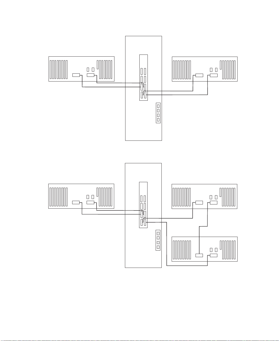
Drawer 2
SPCN
21
Drawer 0
SPCN
21
RIO 1RIO 0
RIO 2
RIO 0
RIO 3
RIO 1
J14
J11
SPCN 0, J15
SPCN 1, J16
System Rack Attached to Three I/O Drawers
Drawer 2
SPCN
21
RIO 1RIO 0
RIO 2
RIO 0
RIO 3
RIO 1
RIO 0
RIO 1RIO 0
Drawer 0
SPCN
221
RIO 1
J14
J11
SPCN 0, J15
SPCN 1, J16
System Rack Attached to Four I/O Drawers
Appendix D. Cabling the System Rack and I/O Rack 59
RIO 0
Drawer 1
SPCN
1
RIO 1
Page 70

RIO 0
Drawer 2
SPCN
221
RIO 1
RIO 0
Drawer 0
SPCN
221
RIO 1
RIO 3
RIO 1
J14
J11
SPCN 0, J15
SPCN 1, J16
RIO 0
Drawer 1
SPCN
1
RIO 1
RIO 0
Drawer 3
SPCN
1
RIO 1
RIO 2
RIO 0
SPCN Cabling
The following figures provide cabling examples for all valid cabling configurations.
Match your configuration to the correct figure and connect your SPCN cables as shown.
System Rack Attached to One I/O Drawer
Drawer 0
SPCN
21
RIO 1RIO 0
RIO 2 RIO 3
RIO 1RIO 0
System Rack Attached to Two I/O Drawers
60 S80, S85 Installation Guide
J14
J11
SPCN 0, J15
SPCN 1, J16
Page 71

RIO 2 RIO 3
RIO 0
RIO 1
Drawer 0
SPCN
21
RIO 1RIO 0
Drawer 1 or 2
J14
J11
SPCN 0, J15
SPCN 1, J16
System Rack Attached to Three I/O Drawers
Drawer 2
SPCN
21
RIO 1RIO 0
RIO 2 RIO 3
RIO 0
RIO 1
J14
J11
SPCN 0, J15
SPCN 1, J16
SPCN
21
RIO 1RIO 0
Drawer 0
SPCN
21
RIO 1RIO 0
Drawer 1
SPCN
21
RIO 1RIO 0
System Rack Attached to Four I/O Drawers
Appendix D. Cabling the System Rack and I/O Rack 61
Page 72

RIO 0
RIO 0
Drawer 2
SPCN
221
RIO 1
Drawer 3
SPCN
1
RIO 1
RIO 2 RIO 3
RIO 0
RIO 1
J14
J11
SPCN 0, J15
SPCN 1, J16
Drawer 0
SPCN
21
RIO 1RIO 0
Drawer 1
SPCN
21
RIO 1RIO 0
62 S80, S85 Installation Guide
Page 73

Appendix E. System Records
Use this appendix to keep a record of your system configuration. Pages are provided
for system information, cabling diagrams, I/O cards installed, and disk drives installed.
Record the Identification Numbers
Record and retain the following information.
S80 and S85 System Rack
Product Name S80 and S85 System Rack
Processor Card
Slots Installed
Serial Number
S80 and S85 System Rack Memory Configuration
Memory Quad Slots Memory Card Size
Quad A M1, M2
M03, M24
Quad B M8, M9
M10, M11
Quad C M12, M13
M14, M15
Quad D M20, M21
M22, M23
S80 and S85 System Rack Cabling Configurations - RIO Cabling
Use the following diagram to record the RIO cabling configuration from the system rack
to the I/O drawer(s).
63
Page 74

RIO 0
Drawer 2
SPCN
221
RIO 1
RIO 0
Drawer 0
SPCN
221
RIO 1
RIO 3
RIO 1
J14
J11
SPCN 0, J15
SPCN 1, J16
RIO 0
SPCN
1
RIO 1
RIO 0
Drawer 3
SPCN
1
RIO 1
RIO 2
RIO 0
S80 and S85 System Rack Cabling Configurations - SPCN Cabling
Use the following diagram to record the SPCN cabling configuration from the system
rack to the I/O drawer(s).
Drawer 2
RIO 0
SPCN
RIO 1
221
RIO 0
SPCN
RIO 1
Drawer 1
Drawer 0
221
SPCN
1
RIO 1
RIO 0
64 S80, S85 Installation Guide
Drawer 3
RIO 2
RIO 0
SPCN 0, J15
SPCN 1, J16
RIO 3
RIO 1
J14
J11
RIO 0
Drawer 1
SPCN
1
RIO 1
Page 75

Primary I/O Drawer Device Records
Use the following tables to keep a record of the options installed in or attached to your
system. This information can be helpful to you or your service representative when you
install additional options in your server.
Table 1. Internal and External Options in Primary Drawer (0)
Location Option Description
Mouse Connector Mouse h Other:____________________________
Keyboard Connector Space Saving h Enhanced h Other:______________
Expansion Slot 14
Expansion Slot 13
Expansion Slot 12
Expansion Slot 11
Expansion Slot 10
Expansion Slot 9
Expansion Slot 8 RESERVED - Service Processor
Expansion Slot 7
Expansion Slot 6
Expansion Slot 5
Expansion Slot 4
Expansion Slot 3
Expansion Slot 2
Expansion Slot 1
Parallel Port
Serial Port 1
Appendix E. System Records
65
Page 76

Table 1. Internal and External Options in Primary Drawer (0) (continued)
Serial Port 2
Refer to the following diagram of your server’s banks/bays when completing Table 2.
10 EIA Unit I/O Drawer
Table 2. Internal Files and Devices in Primary Drawer (0) 10 EIA Unit I/O Drawer
Location/Drive SCSI ID Drive Description
Bank B, Bay 1 Non-SCSI 3.5-Inch 1.44MB Diskette Drive
Bank A, Bay 2 3 CD-ROM Drive
66 S80, S85 Installation Guide
Page 77

Table 2. Internal Files and Devices in Primary Drawer (0) 10 EIA Unit I/O
Drawer (continued)
Location/Drive SCSI ID Drive Description
Bank A, Bay 1 5
Bank C, Drive 1 8
Bank C, Drive 2 9
Bank C, Drive 3 10
Bank C, Drive 4 11
Bank C, Drive 5 12
Bank C, Drive 6 13
Bank D, Drive 1 8
Bank D, Drive 2 9
Bank D, Drive 3 10
Bank D, Drive 4 11
Bank D, Drive 5 12
Bank D, Drive 6 13
Appendix E. System Records
67
Page 78

Additional I/O Drawer Device Records
Use the following tables to keep a record of the options installed in or attached to your
system. This information can be helpful to you or your service representative when you
install additional options in your server.
Table 3. Internal and External Options in Secondary Drawer (1)
Location Option Description / Drawer # Description
Expansion Slot 14
Expansion Slot 13
Expansion Slot 12
Expansion Slot 11
Expansion Slot 10
Expansion Slot 9
Expansion Slot 8
Expansion Slot 7
Expansion Slot 6
Expansion Slot 5
Expansion Slot 4
Expansion Slot 3
Expansion Slot 2
Expansion Slot 1
Table 4. Internal and External Options in Secondary Drawer (2)
Location Option Description / Drawer # Description
68 S80, S85 Installation Guide
Page 79

Table 4. Internal and External Options in Secondary Drawer (2) (continued)
Expansion Slot 14
Expansion Slot 13
Expansion Slot 12
Expansion Slot 11
Expansion Slot 10
Expansion Slot 9
Expansion Slot 8
Expansion Slot 7
Expansion Slot 6
Expansion Slot 5
Expansion Slot 4
Expansion Slot 3
Expansion Slot 2
Expansion Slot 1
Table 5. Internal and External Options in Secondary Drawer (3)
Location Option Description / Drawer # Description
Expansion Slot 14
Expansion Slot 13
Expansion Slot 12
Expansion Slot 11
Appendix E. System Records
69
Page 80

Table 5. Internal and External Options in Secondary Drawer (3) (continued)
Expansion Slot 10
Expansion Slot 9
Expansion Slot 8
Expansion Slot 7
Expansion Slot 6
Expansion Slot 5
Expansion Slot 4
Expansion Slot 3
Expansion Slot 2
Expansion Slot 1
70 S80, S85 Installation Guide
Page 81

Index
A
about this book ix
B
battery
disposal, recycling 43
C
cables
JTAG 48
operator panel 48
RIO 57
SPCN 57, 60
cabling 47
connecting cables 47
connecting the system rack and I/O rack 47
D
device records 65, 68
internal and external options 65, 68
internal files and devices 66
F
fan monitor control card 56
FMC card 56
I
installation, system 1
installing cables 47
J
JTAG connection 48
L
laser vi
laser compliance statement vi
laser compliance statement vi
laser safety information vi
locations
10 EIA unit I/O drawer front 50
I/O Drawer rear 51
I/O rack rear 49
service processor card 55
P
preface ix
product disposal 43
publications, online ix
R
records, device 65, 68
recycling 43
related publications ix
RIO cabling configurations 63
S
safety notices v
laser compliance statement vi
service processor card locations 55
SPCN cabling 60
SPCN cabling configurations 64
system installation 1
system records 63
cabling configurations, RIO 63
cabling configurations, SPCN 64
key serial number 63
machine type/model 63
memory configuration 63
serial number 63
system verification procedure 33
T
trademarks x
U
using
system verification procedure 33
M
memory configuration records 63
N
notices vi
O
online publications ix
operator panel, cable connection 48
71
Page 82

72 S80, S85 Installation Guide
Page 83

Reader’s Comments — We’d Like to Hear From You
Title: Enterprise Server S80 p Series 680 Model S85 Installation Guide
Order Number: 09P1686
Overall how satisfied are you with the information in this book?
Very
Satisfied
Overall Satisfaction hhhhh
Satisfied Neutral Dissatisfied Very
Dissatisfied
How satisfied are you that the information in this book is:
Very
Satisfied
Accurate hhhhh
Complete hhhhh
Easy to find hhhhh
Easy to understand hhhhh
Well organized hhhhh
Applicable to your tasks hhhhh
Satisfied Neutral Dissatisfied Very
Dissatisfied
Please tell us how we can improve this book:
Thank you for your response. May we contact you? h Yes h No
When you send comments to us, you grant us a nonexclusive right to use or
distribute your comments in any way we believe appropriate without incurring
any obligation to you.
73
Page 84

Cut or Fold
Along Line
Fold and Tape
Fold and Tape
Please do not Staple
BUSINESS REPLY MAIL
POSTAGE WILL BE PAID BY ADDRESSEE
Information Development
Department H6DS-9561
11400 Burnet Road
Austin, TX 78758-3493
Please do not Staple
Fold and Tape
NO POSTAGE
NECESSARY
IF MAILED IN THE
UNITED STATES
Fold and Tape
74 S80, S85 Installation Guide
Cut or Fold
Along Line
Page 85

75
Page 86

IBMR
Part Number: 09P1686
Printed in the United States of America
on recycled paper containing 10%
recovered post-consumer fiber.
November 2000
SA38-0582-00
(1P) P/N: 09P1686
 Loading...