

Page 1

Quick Install Guide IBM
IBM Power®System S822LC (8335-GCA and 8335-GTA) Quick
Install Guide
Read all precautions and instructions before you start working on the system and its parts.
Use normal electrostatic discharge (ESD) procedures when working on the system and parts. IBM
recommends wearing gloves and an ESD wrist strap to avoid possible damage to the equipment.
The information about the 8335-GCA and 8335-GTA systems is available online in the IBM Knowledge
Center.
8335-GCA information: https://ibm.biz/QR8335-GCA 8335-GTA information: https://ibm.biz/QR8335-GTA
8335-GCA and 8335-GTA parts
Use this information to find the field-replaceable unit (FRU) part number.
After you identify the part number of the part that you want to order, go to Advanced Part Exchange
Warranty Service. Registration is required. If you are not able to identify the part number, go to
Contacting IBM®service and support.
Page 2

Rack final assembly
Table 1. Rack final assembly part numbers
Index number Part number
Units per
assembly Description
1 45W8836 1 Fixed rail kit - contains left and right fixed rails and
attaching screws
2 74Y9063 1 Cable management arm assembly
3 45W8836 1 Fixed rail kit - contains left and right fixed rails and
attaching screws
4 00E4260 1 Slide rail kit - contains left and right slide rails and
attaching screws
5 1 Electronic Industries Association (EIA) bracket (right side)
6 2 Attaching screw for EIA bracket (right side)
7 00E4501 1 Bezel
8 1 EIA bracket (left side)
9 2 Attaching screw for EIA bracket (left side)
10 00E4260 1 Slide rail kit - contains left and right slide rails and
attaching screws
Figure 1. Rack final assembly
2
Page 3
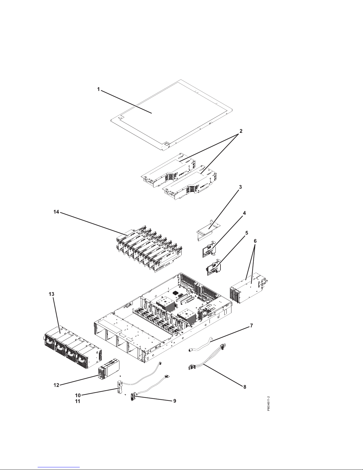
System parts
Figure 2. System parts
3
Page 4
Table 2. System parts
Index number Part number
Units per
assembly Description
1 1 Top access cover assembly
2 00E4485 1 Graphics processing unit (GPU) riser with GPU
00E4484 2 GPU riser without GPU
Note: Requires two riser fillers. See index 23 in Table 3 on
page 5 for the riser filler part number.
00E4475 2 PCIe riser
Notes:
v If a PCIe adapter is present, one riser filler is required.
See index 21 in Table 3 on page 5 for PCIe adapter part
numbers and index 23 in Table 3 on page 5 for the riser
filler part number.
v If a PCIe adapter is not present, two riser fillers are
required. See index 23 in Table 3 on page 5 for the riser
filler part number.
3 1 Power riser cover
4 00E4473 1 Power riser without time-of-day battery slot
5 00E4474 1 Power riser with time-of-day battery slot
Note: The power riser part number does not include the
time-of-day battery. The time-of-day battery is a CR2450N
lithium battery.
6 01AF370 2 Power supply
7 00E4482 1 Disk and fan signal cable
8 00E4481 1 Fan power cable
9 00E4483 1 Front USB cable with connector
10 00E4525 1 Power switch and power switch cable
11 2 Screw
12 00E4252 2 Drive filler
00LY266 2 1 TB disk drive
00LY418 2 2 TB disk drive
00LY409 2 480 GB solid-state drive
00LY410 2 480 GB solid-state drive
00LY411 2 960 GB solid-state drive
00LY412 2 960 GB solid-state drive
00LY423 2 1.92 TB solid-state drive
00YL438 2 3.84 TB solid-state drive
13 00E4256 4 Fan
4
Page 5

Table 2. System parts (continued)
Index number Part number
Units per
assembly Description
14 00E4251 8 Memory riser filler
00LY064 8 Memory riser
78P4489 32 4 GB, 1600 Mhz DDR3 RDIMM
78P4490 32 8 GB, 1600 Mhz DDR3 RDIMM
78P4491 32 16 GB, 1600 Mhz DDR3 RDIMM
78P4492 32 32 GB, 1333 Mhz DDR3 RDIMM
Note: The DIMM FRU might include a heat spreader.
DIMMs with heat spreaders and DIMMs without heat
spreaders can be used together in the system.
Additional system parts
Table 3. Additional system parts.
Index number Part number Units per assembly Description
15 00E4472 1 Disk drive and fan card
Figure 3. Additional system parts
5
Page 6
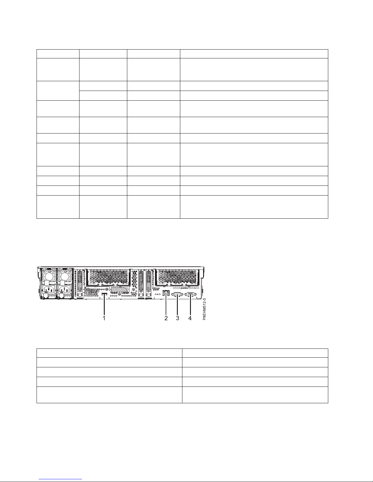
Table 3. Additional system parts (continued).
Index number Part number Units per assembly Description
16 00E4476 1 Screw kit
Note: The screw kit includes 12 screws for the disk drive
and fan card and 16 screws for the system backplane.
17 01AF287 2 8 core 3.625 GHz system processor module
01AF288 2 10 core 3.259 GHz system processor module
18 01AF286 2 Heat sink kit (includes heat sink and thermal interface
material)
19 01AF286 2 Heat sink kit (includes heat sink and thermal interface
material)
20 46K5109 3 PCI filler
21 3 PCIe adapters. Use the feature type of the adapter to find
the FRU part number in PCIe adapter information by
feature type for the 8335-GCA or 8335-GTA.
22 00E4255 2 Graphics processing unit (GPU) shield
23 00E4514 2 Riser fillers for the GPU riser or the PCIe riser
24 00E4470 1 System backplane
25 00E4476 1 Screw kit
Note: The screw kit includes 12 screws for the disk drive
and fan card and 16 screws for the system backplane.
8335-GCA and 8335-GTA ports
Table 4. Port callouts
Identifier Description
1 USB 3.0
2 Ethernet
3 Intelligent Platform Management Interface (IPMI)
4 Video Graphics Array (VGA). Text based capability is
only supported at this time.
Installing and removing 8335-GCA and 8335-GTA parts
Figure 4. Rear view of the system with ports displayed
6
Page 7

Power supplies:
Top cover:
7
Page 8

Disks:
Fans:
8
Page 9

Disk drive fan card:
9
Page 10

Graphics processing unit:
10
Page 11

Memory and memory risers:
11
Page 12

Table 5. Memory locations on memory riser cards
Index number Memory riser card FRU description
33 Memory riser 1 DIMM 1
Memory riser 2 DIMM 5
Memory riser 3 DIMM 9
Memory riser 4 DIMM 13
Memory riser 5 DIMM 17
Memory riser 6 DIMM 21
Memory riser 7 DIMM 25
Memory riser 8 DIMM 29
34 Memory riser 1 DIMM 2
Memory riser 2 DIMM 6
Memory riser 3 DIMM 10
Memory riser 4 DIMM 14
Memory riser 5 DIMM 18
Memory riser 6 DIMM 22
Memory riser 7 DIMM 26
Memory riser 8 DIMM 30
35 Memory riser 1 DIMM 3
Memory riser 2 DIMM 7
Memory riser 3 DIMM 11
Memory riser 4 DIMM 15
Memory riser 5 DIMM 19
Memory riser 6 DIMM 23
Memory riser 7 DIMM 27
Memory riser 8 DIMM 31
12
Page 13

Table 5. Memory locations on memory riser cards (continued)
Index number Memory riser card FRU description
36 Memory riser 1 DIMM 4
Memory riser 2 DIMM 8
Memory riser 3 DIMM 12
Memory riser 4 DIMM 16
Memory riser 5 DIMM 20
Memory riser 6 DIMM 24
Memory riser 7 DIMM 28
Memory riser 8 DIMM 32
Table 6. Memory DIMM feature codes
Supported feature codes (FC) Size
EM50 16 GB RDIMMS, 1333 MHZ, 4 GBIT DDR3 DRAM
EM51 32 GB RDIMMS, 1333 MHZ, 4 GBIT DDR3 DRAM
EM52 64 GB RDIMMS, 1333 MHZ, 4 GBIT DDR3 DRAM
EM53 128 GB RDIMMS, 1066 MHZ, 4 GBIT DDR3 DRAM
Table 7. 8335-GCA memory configuration as a function of the number of DIMMs and risers. You read this table by
selecting the individual DIMM size row in the leftmost column, then move to the right and select the columns for the
memory capacity. The riser quantity value that is listed is the quantity of the memory feature code that can be
ordered, which corresponds to the DIMM size in the leftmost column.
32 GB 64 GB 128 GB 256 GB 512 GB 1024 GB
DIMM
Size DIMMs Risers DIMMs Risers DIMMs Risers DIMMs Risers DIMMs Risers DIMMs Risers
4 GB 8
1
2 16
2
4 32 8
8 GB 8
1
2 16
2
4 32 8
16 GB 8
1
2 16
1
4 32 8
32 GB 32 8
Notes:
1. Default configurations for the listed memory capacity
2. Field upgrade for the 64 GB configuration
The memory risers must be installed in the sequence: (1), then (2), then (3), as shown in Figure 5 on page
14. By default, the first positions (1) are always populated.
13
Page 14

Figure 5. Installation sequence for 8335-GCA memory risers
PCIe adapters:
14
Page 15

Power risers and time-of-day battery:
15
Page 16

System backplane:
16
Page 17

System processor modules:
System backplane (continued):
17
Page 18

System processor modules:
P8EDE521-1
18
Page 19

System processor modules:
P8EDE522-1
If the thermal interface material is damaged, replace it.
This July 15, 2017 edition applies to IBM Power Systems servers that contain the POWER8 processor and to all
associated models.
© Copyright IBM Corporation 2015, 2017.
US Government Users Restricted Rights – Use, duplication or disclosure restricted by GSA ADP Schedule Contract
with IBM Corp.
 Loading...