

Page 1

PrintSuite for iSeries
Advanced Print Utility
User’s Guide
IBM
S544-5351-03
Page 2

Page 3

PrintSuite for iSeries
Advanced Print Utility
User’s Guide
IBM
S544-5351-03
Page 4

Note!
Before using this information and the product it supports, be sure to read the general information in “Notices” on page 133.
Fourth Edition (May 2002)
This edition applies to the licensed program IBM PrintSuite for iSeries: Advanced Print Utility (Program number
5798-AF2), and to all subsequent releases and modifications until otherwise indicated in new editions or technical
newsletters. Be sure to use the correct edition for the level of the product.
Order publications through your IBM representative or the IBM branch office serving your locality. Publications are
not stocked at the address given below.
The IBM Printing Systems Company welcomes your comments. A form for reader’s comments is provided at the
back of this publication. If the form has been removed, you may send your comments to the following address:
INFORMATION DEVELOPMENT
IBM PRINTING SYSTEMS
DEPARTMENT H7FE BUILDING 004M
PO BOX 1900 BOULDER CO 80301-9191
If you prefer to send comments electronically, use one of the following methods:
v Internet: printpub@us.ibm.com
v Fax: 1-800-524-1519 within the U.S. or 1-303-924-6873 outside U.S.
Internet
Visit our home page at http://www.ibm.com/printers
When you send information to IBM, you grant IBM a nonexclusive right to use or distribute the information in any
way it believes appropriate without incurring any obligation to you.
© Copyright International Business Machines Corporation 1996, 2002. All rights reserved.
US Government Users Restricted Rights – Use, duplication or disclosure restricted by GSA ADP Schedule Contract
with IBM Corp.
Page 5

Contents
Figures ...............v
Tables ...............vii
Purpose of this Publication ......ix
APU Enhancements ............ix
Organization of the Manual .........ix
Part 1. Understanding and Preparing
toUseAPU.............1
Chapter 1. Introducing Advanced Print
Utility................3
WhatisAPU?..............3
WhatYouCanDowithAPU.........3
WhyUseAPU?.............4
Printing with and without APU ........4
Printing without APU ..........4
Printing with APU ...........5
APU formatting instructions .........6
Steps in Creating an APU Document ......7
Step 1: Analyzing the Existing Application . . . 8
Step 2: Locating Required AFP Resources....9
Step 3: Using APU to Create a Print Definition . . 9
Step 4: Printing with the Print Definition . . . 10
Chapter 2. Preparing to Use the
Advanced Print Utility ........13
APU Prerequisites and Options........13
Required ..............13
Recommended ............13
Optional ..............13
Initial APU Setup ............14
Font Installation Considerations .......16
Review Document Resource Requirements ....16
Using Fonts with APU...........18
Outline Fonts.............20
Custom Fonts ............21
Image Resources.............24
How APU Works with Image Resources ....24
Building Image Resources ........26
Overlay Resources ............26
How APU Works with Overlays ......27
Building Overlay Resources ........29
Bar Code Resources ...........29
Code 3 of 9 Bar Code Example .......30
POSTNET (Postal Bar Code) Bar Code Example 30
How APU Works with Bar Codes ......30
Part 2. Creating Print Definitions
with APU .............33
Chapter 3. Building an APU Print
Definition for a Single Page Format . . 35
Example of a Single-Page Format Document . . . 35
Example of the SCS File to be Formatted . . . 35
Example of the Formatted File .......36
Setting up a Basic Print Definition .......36
Identifying Resources ..........36
Working with a Print Definition ......37
Further Defining the Print Definition ......38
Working with Copies ...........40
Selecting a Sample Spooled File ......42
Page Layout Options ..........42
Defining Page Segments .........43
Defining Overlays ...........44
Mapping Field Data ...........45
Mapping a Field as Text .........47
Using the Repeat Function ........48
Mapping a Field at Multiple Locations ....49
Chapter 4. Building an APU Print
Definition for Multiple Page Formats . . 51
Example of a Multiple Page Format Document . . 51
Overview of Defining a Multiple Page Format
Document ...............54
Initial Copy for Page Format One ......55
Continuation Page Format ........55
Working with a Print Definition .......55
Identifying Resources ..........55
Starting to Work on a Print Definition ....55
Developing Your Print Definition ......56
Defining Selection Fields .........59
Working with Copies ...........60
Defining the Page Layout.........61
Specifying the Back Overlay ........62
Mapping Fields .............63
Mapping Bar Codes ..........64
Defining Constant Data .........66
Selecting Fonts ............66
Defining Overlays ...........68
Replicating the Contents of Copies ......69
Continuation Page Copies .........71
Part 3. Printing With APU .....77
Chapter 5. Manual and Command Line
Printing with APU ..........79
Methods of Printing with APU ........79
Manually Associating a Print Definition with a
Spooled File ..............79
Panel 1: Apply Print Definition .......80
Panel 2: Apply Print Definition .......81
Panel 3: Apply Print Definition .......82
Using the Apply Print Definition Command . . . 82
© Copyright IBM Corp. 1996, 2002 iii
Page 6

Chapter 6. Automatic Printing with APU
Monitor ..............83
Introduction to the APU Monitor .......83
Understanding How the APU Monitor Works . . . 83
An Example of APU Monitor Processing ....84
A Customer Environment.........84
Implementing the Customer Requirements on the
APU Monitor.............85
Condition of the Output Queue after Processing 86
Configuring APU Monitor .........87
Specifying the Queues APU is to Monitor . . . 88
Configuring APU Monitor Action ......89
Starting APU Monitor ...........97
Stopping APU Monitor ..........98
Part 4. Appendixes.........99
Appendix A. APU Samples......101
Appendix B. User Exits .......103
Processing Phases ............103
User Exit Before ............103
User Exit Middle ............104
User Exit After .............105
Sample User Exit Program .........106
Appendix C. APU Helpful Hints ....111
APYPRTDEF Command ..........111
APU Defaults .............111
Maximum APU Values ..........111
Print Definition Creation..........111
Mapping Data .............112
Copies and Page Formats .........112
Duplex ...............113
Creating Sample Spool Files ........113
Creating Your Own Copy of INVSCS ....113
Recreating INVPRE and INVSCS ......113
Appendix D. AFP Resource
Commands ............115
Creating Font Resources ..........115
Creating Overlay Resources ........116
Creating Page Segment Resources ......117
Appendix E. Rotation Hints .....121
Methods of Rotating Text Data .......121
General Rules .............121
Appendix F. Font Samples ......123
Times New Roman Medium ........123
Helvetica Roman Bold ..........124
Courier ...............125
Glossary .............127
Notices ..............133
Trademarks ..............133
Index ...............135
APU User’s Guide
iv
Page 7

Figures
1. Flow of Data Through APU and OS/400 . . . 5
2. APU Data Structure ..........6
3. APU Concepts ............7
4. Steps to Creating a Document.......8
5. APU main menu panel.........10
6. Set APU Defaults panel ........14
7. Set Print Definition Attributes panel ....15
8. Set Print Definition Attributes panel
(Continued) ............16
9. Super Sun Seeds Invoice ........17
10. Select Field for Mapping panel ......18
11. Map Text panel ...........19
12. Select a Font panel ..........19
13. Map Text panel ...........20
14. Work with Fonts panel.........21
15. Work with Fonts panel.........22
16. Display Font Details on Work with Fonts panel 22
17. Request Addition of the Special Font ....23
18. Add the Special Font to APU ......23
19. Super Sun Seeds Logo .........24
20. Select a Page Segment panel .......25
21. Define Page Segments panel .......25
22. Super Sun Seeds Invoice ........27
23. Select an Overlay panel ........28
24. Define Overlay Positionings panel .....28
25. Page Layout Options - Copy Level .....29
26. Code 3 of 9 Bar Code Example ......30
27. POSTNET Bar Code Example ......30
28. Map Bar Code panel .........31
29. Select a Bar Code Type panel ......31
30. Additional Bar Code Attributes ......32
31. Super Sun Seeds Invoice ........36
32. APU Main Menu panel ........37
33. Work with Print Definitions panel .....37
34. Create a Print Definition panel ......38
35. Define a Print Definition panel ......39
36. Select a Sample Spooled File panel .....39
37. Set Print Definition Attributes panel 1....40
38. Set Print Definition Attributes panel 2....40
39. Work with Copies panel ........41
40. Define a Copy panel .........41
41. Set Page Layout Options panel ......42
42. Define Page Segment panel .......43
43. Create Page Segment Positioning panel 44
44. Define Overlay Positioning panel .....44
45. Create an Overlay Positioning panel ....45
46. Define Field Mapping panel .......45
47. Select Function display.........46
48. Map Text panel ...........47
49. Define Field Mapping Completed panel 47
50. Edit Text Mapping panel ........48
51. Repeat Function of Text Mapping panel 49
52. Repeat Function of Text Mapping panel 50
53. Mapping a Second Position panel .....50
54. Super Sun Seeds Invoice - Page 1 .....52
55. Super Sun Seeds Invoice - Page 2 .....53
56. Super Sun Seeds Invoice - Page 3 .....54
57. APU Main Menu Panel ........56
58. Create a Print Definition Panel ......56
59. Work with Multiple Page Formats panel 57
60. Further Define your Print Definition panel 57
61. Select a Sample Spooled File panel .....58
62. Set Print Definition Attributes (Screen 1) panel 58
63. Set Print Definition Attributes (panel 2) panel 59
64. Define Selection Fields panel.......59
65. Define Selection Field panel .......60
66. Define Selection Fields panel.......60
67. Work with Copies panel ........61
68. Define a Copy panel .........61
69. Set Page Layout Options panel ......62
70. Back Overlay (Terms and Conditions) -
INVBAC.............63
71. Define Field Mapping panel .......64
72. Map Bar Code panel .........65
73. Define Constants panel.........66
74. Create Constant Text panel .......66
75. Select a Font panel ..........67
76. Define Constants panel.........67
77. Define Overlays panel .........68
78. Sample INVALL Overlay ........68
79. Work with Copies panel ........69
80. Suppression panel ..........70
81. Repeating a Suppression panel ......70
82. Sample Packing List Showing Suppression 71
83. Work with Page Formats panel ......72
84. Work with Page Formats panel ......72
85. Create with Copies panel ........73
86. Define Selection Rules panel .......73
87. Define a Rule panel ..........74
88. Define a Rule panel ..........74
89. Define Selection Rules panel .......75
90. Select Spooled File ..........79
91. Apply Print Definition panel .......80
92. Apply Print Definition panel .......81
93. Apply Print Definition panel .......82
94. APU Monitor Processing Sequence.....84
95. APU Monitor before Processing ......85
96. APU Monitor - Action Example ......86
97. APU Monitor Example After Processing 86
98.APUMainMenu...........87
99. Work with APU Monitor ........88
100. Add a New Output Queue .......88
101. Configure APU Monitor Action panel ....89
102. Configure APU Monitor Action panel ....90
103. Define Selection for Input Spooled File panel 91
104. Define Action for Input Spooled File panel 92
105. Action Example for Two Locations .....93
106. Spooled File Location after Processing . . . 94
107. Define Action for Output Spooled File panel 95
108. Define Action for Output Spooled File panel 96
109. APU Main Menu panel ........97
110. Start APU Monitor panel ........97
© Copyright IBM Corp. 1996, 2002 v
Page 8

111. Stop APU Monitor panel ........98
112. Create Temporary Resource File .....115
113. Copy From PC Document (CPYFRMPCD)
panel ..............115
114. Create Font Resource (CRTFNTRSC) panel 116
115. Create Temporary Resource File panel 116
116. Copying Overlay File from Folder ....117
117. Create Overlay (CRTOVL) panel .....117
118. Create Temporary Resource File .....118
119. Copy Page Segment to Temporary File 118
120. Create Page Segment (CRTPAGSEG) panel 118
121. Rotation Hints ...........121
122. Times New Roman Medium ......123
123. Helvetica Roman Bold ........124
124. Courier Font Samples .........125
vi APU User’s Guide
Page 9

Tables
1. Field Mapping Values .........48
2. Samples in the QAPU Library ......101
3. APU Print Engine Processing Phases 103
4. Parameters Passed to the Before Initialization
User Exit .............103
5. Parameters Passed to the Middle User Exit 104
6. Parameters Passed to the User Exit After the
AFPDS Spooled File has been Created . . . 105
© Copyright IBM Corp. 1996, 2002 vii
Page 10

viii APU User’s Guide
Page 11

Purpose of this Publication
This publication helps you to use the IBM PrintSuite for iSeries Advanced Print
Utility (APU). It focuses on the concepts of APU, using a series of application
examples to demonstrate how APU works.
APU has extensive on-line help; we do not duplicate that information here. For
details on the concepts of Advanced Function Presentation (AFP), refer to iSeries
Guide to AFP and PSF, S544-5319.
APU Enhancements
The following features have been made available by the current modification level
of APU:
1. Duplex Printing is now available. Refer to “Page Layout Options” on page 42
for a description of how the capability is used, including restrictions on its use.
2. Fields in the SNA Character String (SCS) file can now be mapped to multiple
locations. Refer to “Mapping a Field at Multiple Locations” on page 49.
3. Outline fonts are now included in the font set. Refer to “Outline Fonts” on
page 20.
4. The APU Monitor has been enhanced to include conditional processing
capabilities. Refer to Chapter 6, “Automatic Printing with APU Monitor” on
page 83.
Organization of the Manual
This manual is organized into three parts, as follows:
v Part 1 - Understanding and Preparing to use APU
The two chapters in this part introduce new APU users to the capabilities and
features of APU:
1. Introducing Advanced Print Utility describes what you can do with APU.
2. Preparing to use the Advanced Print Utility describes tasks you need to
perform before using APU. You are also given an orientation to using the
APU panels.
v Part 2 - Creating Print Definitions with APU
Each of the two chapters in this part provides you with a procedure for creating
a print definition. One chapter provides the procedure for creating a print
definition for a single-page document; the other for a multiple page document.
New APU users will find it useful to create a sample print definition using one
of these procedures before creating a production-level print definition.
v Part 3 - Printing with APU
The material in this part describes the concepts and procedures for printing your
documents once you have created a print definition.
© Copyright IBM Corp. 1996, 2002 ix
Page 12

x APU User’s Guide
Page 13

Part 1. Understanding and Preparing to Use APU
Chapter 1. Introducing Advanced Print Utility ..3
WhatisAPU?..............3
WhatYouCanDowithAPU.........3
WhyUseAPU?.............4
Printing with and without APU ........4
Printing without APU ..........4
Printing with APU ...........5
The Design Phase...........5
The Production Phase .........6
APU formatting instructions .........6
Steps in Creating an APU Document ......7
Step 1: Analyzing the Existing Application . . . 8
Questions you need to Ask .......8
Example of Sample Spooled File (Source Input
Data) ...............8
Step 2: Locating Required AFP Resources....9
Step 3: Using APU to Create a Print Definition . . 9
Defining Page Formats ........10
Defining Copies ...........10
Step 4: Printing with the Print Definition . . . 10
Chapter 2. Preparing to Use the Advanced Print
Utility ................13
APU Prerequisites and Options........13
Required ..............13
Recommended ............13
Optional ..............13
Initial APU Setup ............14
Font Installation Considerations .......16
Review Document Resource Requirements ....16
Using Fonts with APU...........18
Outline Fonts.............20
Custom Fonts ............21
Image Resources.............24
How APU Works with Image Resources ....24
Building Image Resources ........26
Overlay Resources ............26
How APU Works with Overlays ......27
Building Overlay Resources ........29
Bar Code Resources ...........29
Code 3 of 9 Bar Code Example .......30
POSTNET (Postal Bar Code) Bar Code Example 30
How APU Works with Bar Codes ......30
© Copyright IBM Corp. 1996, 2002 1
Page 14

2 APU User’s Guide
Page 15

Chapter 1. Introducing Advanced Print Utility
Use this chapter to gain an understanding of what the IBM PrintSuite for iSeries
Advanced Print Utility (APU) can do for you, including:
v “What is APU?”
v “What You Can Do with APU”
v “Why Use APU?” on page 4
v “Printing with and without APU” on page 4
v “APU formatting instructions” on page 6
v “Steps in Creating an APU Document” on page 7
What is APU?
Advanced Print Utility (APU) is part of the Advanced Function Presentation (AFP)
PrintSuite family of document-creation systems that enables you to use SCS files as
input to APU and then to transform that input to “full-page” electronic output,
with pages that include electronic forms, image, bar codes, lines, boxes, and text in
a variety of fonts.
APU provides an interactive design approach that is independent of the
application program.
v The input to APU is the line-mode (SCS) output file that the line-of-business
application creates.
v The output of APU is an AFP spooled file.
What You Can Do with APU
Output specifications for iSeries application programs generate either SNA
Character Stream (SCS) or AFP spooled files. APU works on SCS spooled files. SCS
is a line-oriented datastream that for the most part uses preprinted forms to create
the final document. With APU, you can eliminate the need for preprinted forms.
Instead, you create a completely electronic document. With APU, you can:
v Create multi-copy documents, with each page customized
v Use data that is contained within a page to determine which of multiple output
formats to use
v Remap any field that the input SCS pages contain (change position, font,
orientation, color, and so on)
v Print application data in any of the standard bar code symbologies
v Add document elements such as electronic forms (overlays), images, lines, boxes,
and constant text
v Place a new application into production for automatic processing
v Manage the production of input and output files, including the routing of
different output files to different queues, printers, and output bins
v Implement user-defined programs that can address unique document or
document distribution requirements
APU provides an interactive interface for defining new output applications. For
simpler applications, APU provides a “fast path”. You use the current spooled file
(SCS) interactively to redefine the formatting of application data.
© Copyright IBM Corp. 1996, 2002 3
Page 16

Why Use APU?
APU assists you in building AFP-compatible electronic output. Effective electronic
output can provide significant benefits to an organization, particularly in the areas
of information systems costs, process reengineering, and better communications,
for example:
v Replacing preprinted multipart forms with electronic forms supplies significant
cost savings.
– You can print a variety of different forms one after the other without
switching forms at the printer.
– You can eliminate carbon forms by printing multiple copies of the same page,
that includes the capability of varying the output on each copy.
– You can eliminate storage space for preprinted forms because the forms are
stored electronically rather than physically occupying office space.
– You can change the form outside of the application program, and you do not
need to scrap or reorder preprinted forms.
v Documents, whether printed, stored, or viewed, are critical to the workflow in
any organization. The capabilities of electronic documents provide a wealth of
opportunities to reengineer organizational processes. In fact, in many industries,
document reengineering such as bar coding is a “must.” Coding an electronic
document with bar code, optical character recognition (OCR), magnetic ink
character recognition (MICR), and images enables you to easily integrate the
document into the workflow.
v Electronic documents are more effective documents. Document elements, such as
images, text, and overlays, allow you to compose a document that does a better
job of communicating or marketing. Electronic flexibility, the ability to change a
document dynamically down to the individual transaction level, provides a wide
variety of application possibilities. Electronic documents project the image of a
strong, professional organization.
For more information about the benefits of AFP, refer to iSeries Guide to AFP and
PSF.
Printing with and without APU
This section describes the situation in environments that do and do not use APU.
Printing without APU
APU provides an application-independent, end-user approach to page and
document formatting. Without APU, the application programmer can format pages
using either specifications within the application program or DDS (Data
Description Specifications), which is external to the application program.
Formatting within the program (also called internally or program-described) only
provides for line-oriented pages of output. Formatting with DDS (actually a part of
the printer file) actually provides for comprehensive AFP pages and documents.
There are DDS keywords not only for field positioning but also for every
document element (overlay, image, font, bar code, and so on) found in complex
application output.
Both these methods of formatting pages, however, are integrated with the
application program. This is an advantage when you want to precisely customize
each page based on logic or data within the program. This is a disadvantage when
you would like to separate the processing of the application program from the
complex formatting of each page. This is even a bigger disadvantage if there is no
4 APU User’s Guide
Page 17
access to the application program source code or no programming skills exist
in-house to implement changes to output pages or documents.
Printing with APU
Using APU requires no programming skills, enabling individuals with graphics
and layout ability to design the appearance of the printed page and to easily make
changes to printout appearance.
Note: Exact print results depend on the type of printer you have. Refer to IBM
Printing Systems: Printer Information, S544-5750, for the specific capabilities of
your printer.
Without AFP and APU, the application programmer codes all of the formatting
information in the application program or printer file and runs the program to
generate an output file. The output file is placed on a system spool and directed to
a printer.
Output Queues
Application
Create
Print
Definition
Print
Program
Print
Definition
Spool
Monitor
Print
Engine
Output Queues
Spool
AFP
Resources
PSF/400
AFP
Printer
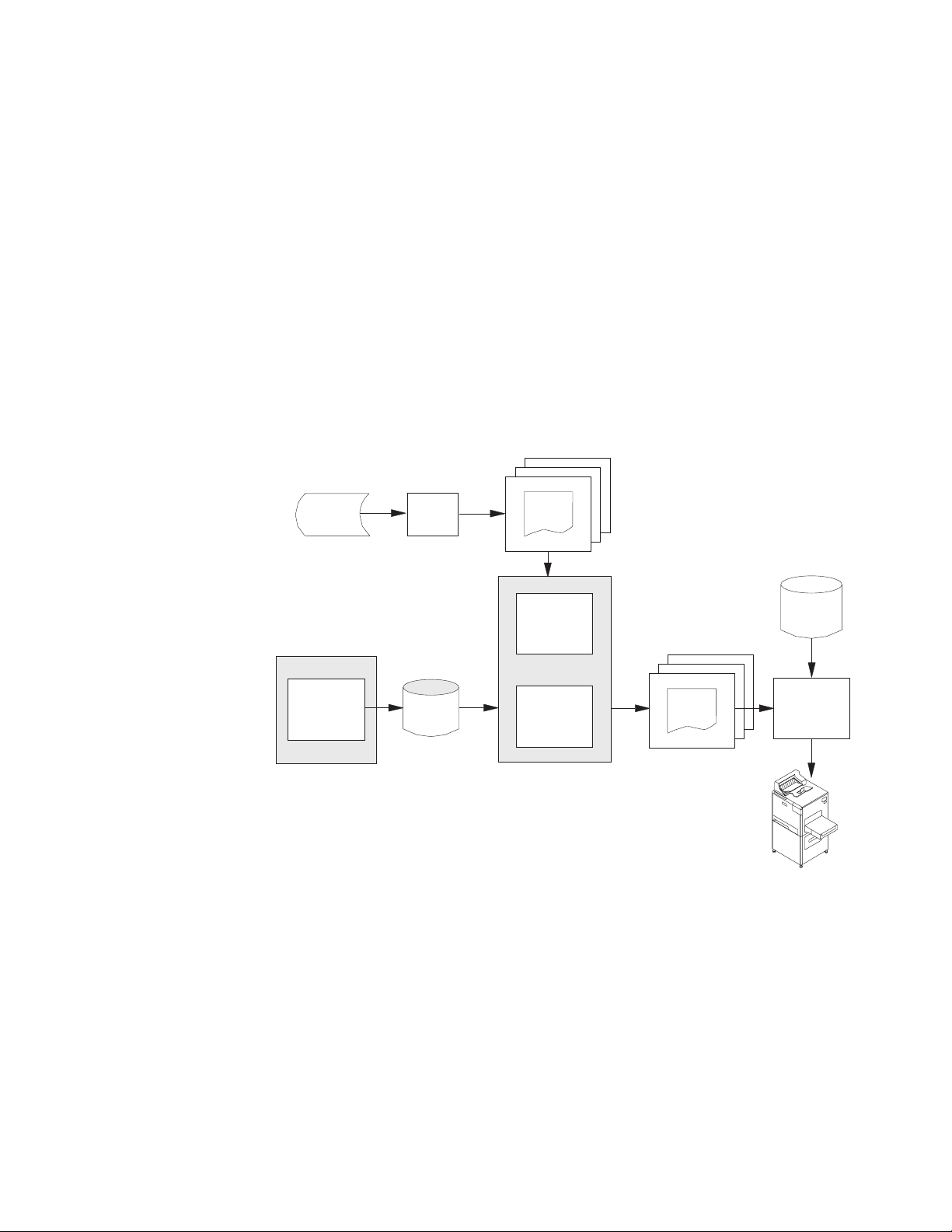
Figure 1. Flow of Data Through APU and OS/400
Figure 1 illustrates the processing flow of APU. There is a design phase and a
production phase.
The Design Phase
The new output application is defined in the design phase, which is done once (or
when changes are required). You do this interactively. The spooled output file from
the existing application is retrieved and used in the design process. The output of
this design phase is a set of formatting rules that are stored in an APU print
definition.
Chapter 1. Introducing Advanced Print Utility 5
Page 18
The Production Phase
With the new print application designed, it is ready to be placed into production.
You define the desired production characteristics to APU. These characteristics
include how to identify the target spooled file, which print definition to use, what
user-specific programs should be called during processing, and the disposition of
both the input and output spooled files. With this information in place, you start
the APU Monitor.
The APU Monitor automatically monitors iSeries output queues, looking for the
specified spooled file. When that target file is identified, it is retrieved and passed
to the APU print engine. The APU print engine uses the formatting instructions
contained in the APU print definition to create a new AFP output file and place it
in an output queue.
At this point, standard iSeries print management takes over. When the new file is
to be printed, PSF/400 manages the printing process (including the retrieval and
management document resources such as overlays, images, and fonts) to an IPDS
printer. Alternatively, the new print file can be routed through Host Print
Transform to an HP-PCL printer.
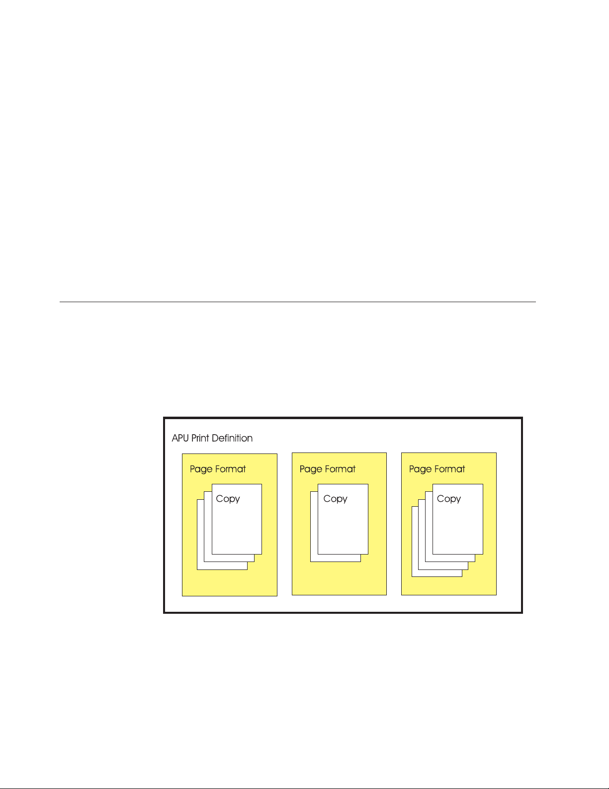
APU formatting instructions
APU enables you to build a print definition, which is a set of instructions for
formatting the data that is contained in a spooled print file. A print definition can
contain one or more page formats, enabling you to change formatting instructions
for different pages in the spooled file. Within the page format, you can define one
or more copies of each input page. Figure 2 shows the relationship among these
APU concepts.
6 APU User’s Guide
Figure 2. APU Data Structure
You can specify a single page format in a print definition, if all of the pages in
your spooled file are formatted in the same way. An application that might require
only one page format is a one-page form such as an invoice, where all of the fields
on the form are predefined, and a second page is never required.
Even though you define only one page format in the print definition, you can still
use the APU multiple copy function to produce different copies of the same page,
Page 19
as would be done with hard copy multipart forms. You can, for example, suppress
the price on the packing slip and print some inventory control information on the
packing slip as a bar code.
When you use APU, each copy can be different. The same data can be printed at a
different position, and different attributes can be used with each copy. For
example, the customer address from an invoice can be placed on the right side of
the first (“original”) copy and on the left side and in a different font on the second
copy.
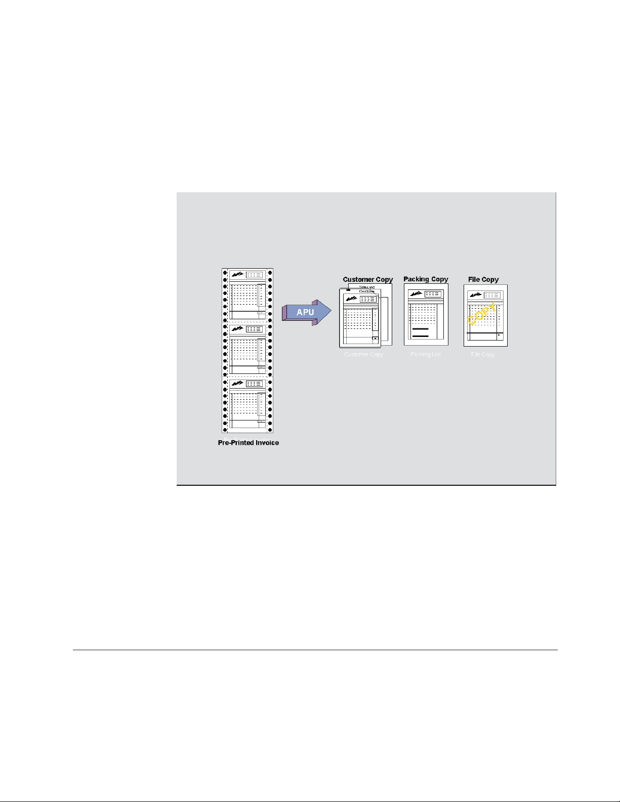
Applications requiring multiple page formats in the print definition might be
Figure 3. APU Concepts
billing statements that could have so many line items that two pages instead of
one are required to list all of the items ordered. In this case, you would want to
define one page format to be used for the first page of each customer bill and
another page format to be used for those customers requiring a second page.
To determine what page format is used for each input data page, you define fields
in the data that can be evaluated by APU. For example, if the input data contains a
field with “PAGEnOFm” in it, you can specify that field to APU and have the
contents of the n and m fields evaluated to determine if a second page format
should be used.
Steps in Creating an APU Document
To create a document that takes advantage of the functions that are provided by
AFP and APU, you need to perform the tasks shown in Figure 4 on page 8.
Chapter 1. Introducing Advanced Print Utility 7
Page 20

Analyze the
SCS job
Create
AFP Resources
with AFP tools
Create the
Print Definition
Run the
Print Definition
Document structure
- Page format
- Page copy
- Data identification
- Resources
identification
- Trigger for conditional
processing
- Font
- Page Segment
- Overlay
Define APU Defaults
- Select unit of
measure
- Select font
- Select paper size
. . .
-
Create print definition
- Define page format
- (cond. processing)
- Create copy
- (Mapping)
. . .
- ( )
Figure 4. Steps to Creating a Document
Step 1: Analyzing the Existing Application
Questions you need to Ask
The first step in creating a document is to examine the contents of the current
application program that is output by asking these questions:
v Is the application currently being printed on preprinted forms? If so, how
complicated is the information on the preprinted forms? If the preprinted form
contains only a few boxes and text strings, you might consider using the APU
functions to include those items in the APU print definition. If the form is
complex, you should probably use another program, such as the Overlay Utility
in the Advanced Function Printing Utilities for iSeries program product, to
create an electronic overlay. For more information, see Chapter 2, “Preparing to
Use the Advanced Print Utility” on page 13.
v Is the application currently being printed on multipart forms? If so, do the forms
all contain the same information, or is some of the data suppressed on some
copies?
v Is the same page format used for all pages in the file? Could you improve the
appearance of the output by using a different format for pages of different types,
such as a different layout for the first output page than for subsequent
continuation pages?
v If you want to use more than one page format in the AFP output, examine the
contents of a spooled file that is produced by the application. What information
is contained in the print data that APU can use to determine which page format
is to be used for each type of output page?
v What fonts will you need to produce effective output?
v Would you like to add any image data to the output?
v Would you like to add any bar code data to the output?
v What type of AFP printer will you use to print the job? Some AFP printers do
not support all of the AFP data stream objects, such as bar codes. Refer to IBM
Printing Systems: Printer Information, S544-5750, for details about printer
capabilities.
Run APU manually
Work with APU monitor
8 APU User’s Guide
Example of Sample Spooled File (Source Input Data)
An example of the sample spooled file (source input data) that you would use to
build a print definition is given below:
Page 21

LOS ARBOLES DEL MUNDO SAME
32483 ARBOL LANE
MESA VERDE
IL 54078-9390
141 31341 1/26/98 2/26/98
900 EA 00001200 ARBOLES DEL SUR 45.00 40,500.00
951 CT 11005011 LASSO RED SEEDS 892.23 48,510.73
46 DZ 11005014 SCARLET NANTES SEEDS 5.90 271.40
45 BZ 11005015 CHANTENAY SEEDS 2.19 98.55
951 PK 11005018 EARLY BANTAM SEEDS .38 361.38
4 BX 11057893 AFRICAN DAISY, SEEDS 2.35 9.40
100 EA 31321655 SEMILLAS DEL SUS SOMBEROS 24.95 2,495.00
1000 BX 56413213 POT POT 7.65 7,650.00
98 PK 84512023 OREGON SPRING TOMATO SEED .97 95.06
1/26/98 N10 MICHELE GOODACRE
Thank You .....
Because you have ordered
over $500 of trees this
year, on your next tree
order you will receive
a 10% discount.
$99,991.52
LOS ARBOLES DEL MUNDO
2/26/98 $99,991.52
32483 ARBOL LANE
MESA VERDE
IL 540789390
Note: There are some restrictions on the spooled file to be copied. Refer to the
help text for the copy spool file (CPYSPLF) command for details of these
restrictions.
Step 2: Locating Required AFP Resources
If your application analysis in Step 1 identified required overlays, images, or fonts,
those print resources need to be available before you can proceed with the APU
design function. APU does not create these print resources, but other IBM and
vendor programs as available that do. Refer to Chapter 2, “Preparing to Use the
Advanced Print Utility” on page 13.
Step 3: Using APU to Create a Print Definition
After APU is installed, enter “GO QAPU/APU” on a command line to display the
APU main menu, as shown in Figure 5 on page 10.
Page
1
Chapter 1. Introducing Advanced Print Utility 9
Page 22

APU IBM Advanced Print Utility
Select one of the following:
Build and Test APU Print Definitions
1. Work with Print Definitions
2. Work with Spooled Files
Run APU in Batch Mode
3. Work with APU Monitor
4. Start APU Monitor
5. End APU Monitor
Configure APU
6. Set APU Defaults
7. Work with Fonts
8. Configure APU Monitor Action
Selection or command
===> 1
F3=Exit F4=Prompt F9=Retrieve F12=Cancel F16=System main menu
F23=Set initial menu
Figure 5. APU main menu panel
Initially, you may need to set the APU defaults if they were not previously set. For
more information, see “Initial APU Setup” on page 14.
Creating a print definition includes defining page formats and defining copies. We
describe these tasks in the sections that follow.
Defining Page Formats
When you create a print definition, you must specify whether the print definition
will contain one or more page formats. If your print definition will contain only
one page format, APU uses a fast path to map the spooled file data and define
other document resources such as overlays and images.
However, if your print definition will contain multiple page formats, you must
define the fields in the spooled file that APU can use to determine which page
format to use for each page of input data. See “Example of a Multiple Page Format
Document” on page 51 for a detailed description of the panels in APU that you use
for a print definition with multiple page formats.
After you have set up the conditions you want APU to use to select a page format,
you can then specify the formatting instructions for each output copy.
Defining Copies
A page format needs a minimum of one copy. APU provides the first *ORIGINAL
copy with all related default values. Before you create additional copies, you need
to define or modify all elements common to all copies. All work that is done on
the first copy can be reused by any additional copies.
Step 4: Printing with the Print Definition
To test how your application output will appear with the new print definition
applied, select Work with Spooled Files from the APU Main Menu. On that panel
you can select an existing spooled file to which you can apply your print
definition.
10 APU User’s Guide
Page 23

After you specify which print definition to apply, APU creates another spooled file
and sends it to the output queue that you select. You will probably need to
experiment some to get the data lined up with the electronic form or to refine the
conditional tests that APU performs to select page formats.
When you have completed testing of the print definition, you are ready to put the
application into production. This involves defining how the production process is
to work, then starting the APU Monitor.
Use the Work with APU Monitor option on the APU Main Menu to define how
the target spooled file is identified, which print definition(s) will be applied, any
special user-specific processing that should be done, and the disposition of the
input and output files when production processing completes.
Once these options are defined, the APU Monitor can be started. Use the Start the
APU Monitor option on the APU Main Menu. At this point, the production
process is automatic. When the target spooled file is identified, it is automatically
selected and processed based on your definition. Refer to Chapter 6, “Automatic
Printing with APU Monitor” on page 83 for detailed information.
Chapter 1. Introducing Advanced Print Utility 11
Page 24

12 APU User’s Guide
Page 25

Chapter 2. Preparing to Use the Advanced Print Utility
Before building your first APU print definition, review the following installation
and planning considerations:
v “APU Prerequisites and Options”
v “Initial APU Setup” on page 14
v “Font Installation Considerations” on page 16
v “Review Document Resource Requirements” on page 16
v “Using Fonts with APU” on page 18
v “Image Resources” on page 24
v “Overlay Resources” on page 26
v “Bar Code Resources” on page 29
APU Prerequisites and Options
Required
Print Services Facility for iSeries (PSF for iSeries) is the AFP printing subsystem on
OS/400. PSF for iSeries is used when AFP print files are to be printed on
Intelligent Printer Data Stream (IPDS) printers. Since APU creates AFP output, PSF
for iSeries is required to print APU applications to IPDS printers. AFP output files
can also be printed on HP-PCL printers by using Host Print Transform (a
component of OS/400) services. There are performance differences and print
management differences between IPDS and PCL printing.
Recommended
AFP Font Collection provides comprehensive libraries of AFP fonts for use in APU
applications. Standard document typefaces, such as Helvetica, Times New Roman,
and Courier, are included in over 48 languages. The font libraries are provided in
240 dpi (dots per inch), 300 dpi, and outline formats, corresponding to different
printer resolutions.
A note on Examples
The examples in this publication assume that you have read and write access
to the QAPU library and to the resources it contains. You may need to contact
your system administrator to get this authorization. If the QAPU resources
have been moved, you may also need to obtain the name of the locally
defined library name where these resources are stored.
Optional
AFP Utilities for iSeries consists of three utilities that complement APU
applications:
v Overlay Utility provides the capability to create electronic forms.
v Print Format Utility enables you to create quick, specialized applications, such
as bar coded labels.
v Resource Management Utility assists in managing overlay and image resources.
Client Access for iSeries, in addition to client/server support, integrates the AFP
Workbench into the Windows or OS/2 client. This provides full graphical viewing
© Copyright IBM Corp. 1996, 2002 13
Page 26

of AFP documents, as well as the ability to search, print, and fax what is viewed.
In addition, the full AFP Workbench includes the IBM AFP Printer Driver for
Windows. Use this standard Windows driver to create overlays and page segments
from any Windows application.
Non-IBM document product tools, of which many exist, assist you in creating
fonts, images, and overlays.
Initial APU Setup
APU provides for several levels of default print settings:
v At the APU level
v At the print definition level
v At the copy level
At these levels, you can set print attributes and environment attributes, such as
unit of measure, resource libraries, and default font family.
Note: You cannot set all attributes at all levels.
Use option 6 (Set APU Defaults) on the APU main menu to display the Set APU
Defaults panel, which is shown in Figure 6.
Note: Refer to “APU Defaults” on page 111 for some helpful hints on setting APU
defaults.
Set APU Defaults
Type choices, press Enter.
Unitofmeasure.... *INCH *INCH, *CM, *ROWCOL, *UNITS
Decimal point character . . or ,
Font family...... HELVETICA Value F4 for List
Color......... *DEFAULT *DEFAULT, Value F4 for List
Definition library . . QAPU Name
Code Page . ...... T1V10500 Name F4 for List
Addl. resource libs. . IMAGES Name
Job description . . . . QYPUJOBD Name
Library....... *LIBL Name, *LIBL
F3=Exit F4=Prompt F12=Cancel
Figure 6. Set APU Defaults panel
OVERLAYS Name
Name
Name
The values that are shown above are the values APU will use unless they are
superseded at print definition level or copy level print definition or copy level. The
defaults selected in the example above are:
v Inches for unit of measure
v Helvetica for font family
v APUDATA as the library to store APU print definitions
v T1V10500 as the default code page (this is an international code page)
14 APU User’s Guide
Page 27

v For the Job description, we recommend that you use QYPUJOBD in the QAPU
library.
Two additional resource libraries, IMAGES and OVERLAYS, were also selected as
defaults because APU looks in these libraries for document resources, such as page
segments and overlays.
You can specify defaults when you first begin an APU print definition. This
display is shown in Figure 7.
Set Print Definition Attributes
Print Definition . . : SUPER2
Library ......: QAPU
Type choices, press Enter.
Unit of Measure .... *INCH *INCH, *CM, *ROWCOL, *UNITS
Default line increment *INPUT *INCH *INPUT, Value
Default column inc. . . *INPUT *INCH *INPUT, Value
Page length . . . . . . *INPUT *INCH *INPUT, Value
Page width ...... *INPUT *INCH *INPUT, Value
Top margin (down) . . . 0 *INCH 0, Value
Left margin (across) . 0 *INCH 0, Value
Page orientation . . . 0 *INPUT, 0, 90, 180, 270
Apply field attributes 1=Yes
More...
F3=Exit F12=Cancel F22=Set Units
Figure 7. Set Print Definition Attributes panel
Note: When you specify *INPUT for the Page orientation field, APU always
attempts to create the output in Portrait mode by default. APU attempts to
perform text rotation according to the values specified for the Page length
and Page width fields.
The print definition defaults add page layout attributes such as page size, line and
column increments, and margins.
The continuation of the panel is shown in Figure 8 on page 16:
Chapter 2. Preparing to Use the Advanced Print Utility 15
Page 28

Set Print Definition Attributes
Print Definition . . : SUPER2
Library . .....: QAPU
Type choices, press Enter.
Default font family . . *APUDFT *APUDFT, Value F4 for List
Point size ..... *CALC *CALC, Value
Bold ........ 1=Yes
Italic . . . . . . . 1=Yes
Default Color..... *APUDFT *APUDFT, Value F4 for List
Addl. resource libs. . Name
F3=Exit F4=Prompt F12=Cancel
Figure 8. Set Print Definition Attributes panel (Continued)
When you define a copy, you can specify print attributes at this level as well. You
can override print attributes or default to the attributes specified at the print
definition or APU level.
Font Installation Considerations
Name
Name
Name
Bottom
APU installation loads the APU software on to the iSeries and creates the QAPU
library. During the installation process, APU builds the font database. APU
provides a standard interface to the fonts on the system and must synchronize its
database with the actual fonts that are resident on the system.
If you are adding AFP fonts to your system while you are installing APU, you
should load the fonts prior to installing APU. If you add font libraries after
installing APU, you will need to synchronize the font database again. To do this,
issue the following command to run the synchronization program:
call qapu/qypusync
After APU is installed, you can access the APU Main Menu by entering GO
QAPU/APU.
Review Document Resource Requirements
APU creates complex electronic documents, combining many elements into each
completed page. The building blocks of these electronic pages are electronic
overlays, fonts, bar codes, and images (that are called page segments in AFP). The
example below, output from an invoicing application for the Super Sun Seeds
Company, illustrates those elements:
16 APU User’s Guide
Page 29
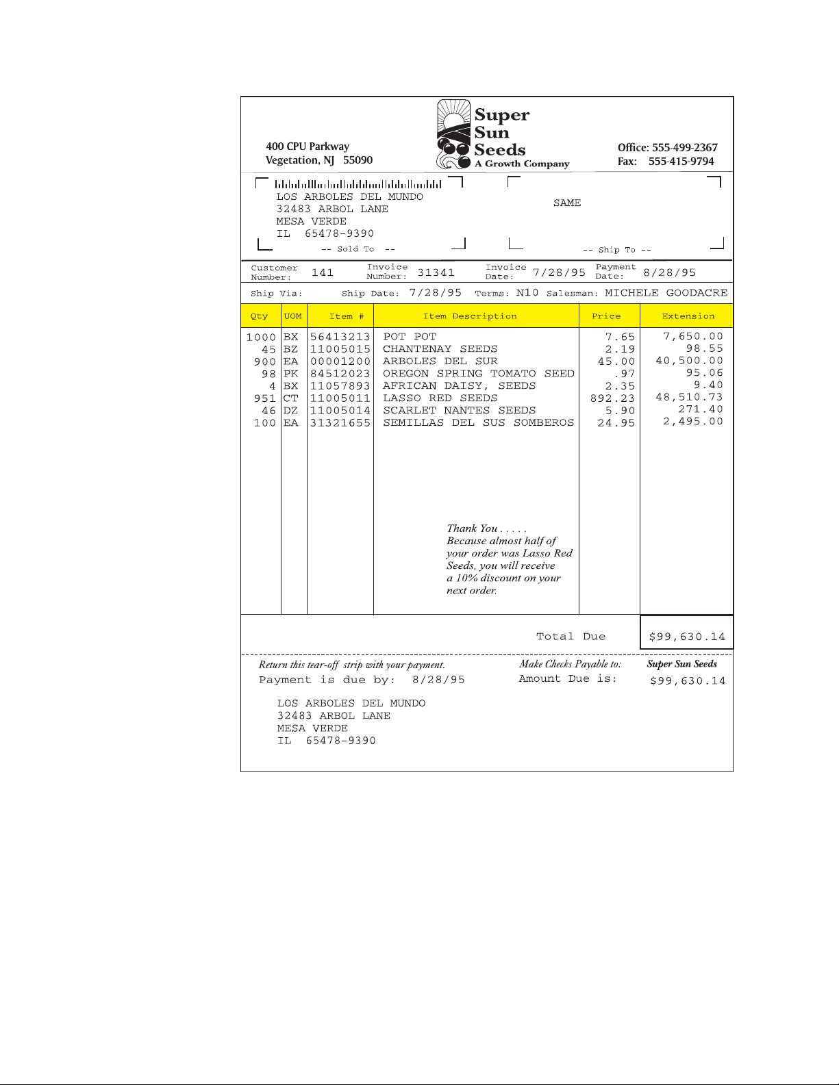
Figure 9. Super Sun Seeds Invoice
You will note the many characteristics that make this invoice an effective
document:
v Static sections of the page built into an overlay
v Company logo and accent image
v Use of a variety of fonts
v Use of bar coding — POSTNET for the zip code
The following sections use the Super Sun Seeds example to provide a close look at
the key resources that comprise APU electronic documents: how they are used on
the iSeries, how they are created, and how APU works with them.
Chapter 2. Preparing to Use the Advanced Print Utility 17
Page 30

Using Fonts with APU
The examples in the remainder of this manual use the fonts in the AFP Font
Collection. You should verify that you have these fonts available before going
on. Your results may differ depending on the fonts defined on your system.
APU provides an interface that makes selecting fonts simple. During installation,
APU determines which fonts (character sets) are on your system and loads them
into this interface. APU distinguishes between IBM-supplied fonts and your own
custom fonts.
Most common fonts are selected by font family, typeface (normal, bold, italic, and
combinations), and point size. This is how APU selects fonts for your document.
You can select fonts for constant text or for text from the application. The example
below shows how to map application data to a new font.
To follow the examples provided in the remaining sections of this chapter, you will
need a print definition and a sample spooled file.
v Refer to “Setting up a Basic Print Definition” on page 36 for instructions on how
to create a print definition you will call MYPRTDEF.
v Refer to “Further Defining the Print Definition” on page 38 for instructions on
how to select a sample spooled file called INVPRE.
Select option 12 (Work with...).
Select option 10 (Define) on the Work with Copies panel and then select Define
field mapping on the Define a Copy panel to have the Define Field Mapping
panel appear.
From the Define Field Mapping panel, use F14 to mark the beginning of the
“Improved Printing Corp.” field and F15 to mark the end of the field. Once you
have taken these two steps, the Select Function panel appears.
Define Field Mapping
Spooled file ....: INVPRE Page/Line......: 1/1
Control........ Columns . . . . . . . : 1 - 78
*...+....1....+....2....+....3....+....4....+....5....+....6....+....7....+...
IMPROVED PRINTING CORP : Opt Function :
PERFORMANCE BOULEVARD : :
PRINTERSVILLE : 1 Map as Text :
CO 45789-2637 : Map as Bar Code :
F3=Exit F11=Hide mapping : F12=Cancel :
F15=End field F16=Delete range : :
Mark end of field, press F15 or press F :....................................:
......................................
: Select Function :
::
: From Row / Column : 12 / 12 :
: Length......: 22 :
::
: Type option, press Enter. :
: 1=Select :
::
: Suppress :
::
18 APU User’s Guide
Figure 10. Select Field for Mapping panel
Page 31

Select MapasTextto change the font that is used for the name. The Map Text
panel appears.
Spooled file . . . . : INVPRE Page/Line......: 1/1
............................................................................
: Map Text :
: Type choices, press Enter. :
: From Row / Column : 12 / 12 :
: Mapping.....: 1/ 1 :
: Length ...... 22 :
: Position across . . 1.1 *INCH Value :
: Position down . . . 2 *INCH Value :
: Font family . . . . *PRTDEF *PRTDEF, Value F4 for list :
: Point size . . . *CALC, Value :
: Bold . . .... 1=Yes :
: Italic . .... 1=Yes :
: Rotation ..... *DEFAULT *DEFAULT, 0, 90, 180, 270 :
: Color ....... *PRTDEF *PRTDEF, Value F4 for list :
: More...:
...........................................................................:
F4=Prompt F12=Cancel
Define Field Mapping
F22=Set Units
Figure 11. Map Text panel
Position the cursor on the Font family field, press F4 to have the font database
displayed, then select the font you want.
Define Field Mapping
S ............................................................................
C : Select a Font :
.: :
: : Font family . . . . . . HELVETICA Name, Generic*, *ALL :
: : Point size ..... *ALL Value, *ALL :
: : Bold . . ...... 1=Yes, 0=No :
: : Italic . ...... 1=Yes, 0=No :
:: :
: : Type Options, press Enter. :
: : 1=Select 5=Details :
:: :
: : Opt Font family Size Style :
:: :
: : HELVETICA 11 Bold :
: : HELVETICA 11 Bold-Italic :
: : HELVETICA 12 Normal :
: : HELVETICA 12 Italic :
: : 1 HELVETICA 12 Bold :
: : HELVETICA 12 Bold-Italic :
:: More... :
: : F5=Refresh F12=Cancel :
:: :
: :..........................................................................:
Figure 12. Select a Font panel
Select Helvetica Bold in 12-point, and press Enter. The Map Text panel appears
again.
Chapter 2. Preparing to Use the Advanced Print Utility 19
Page 32

Spooled file . . . . : INVPRE Page/Line......: 1/1
............................................................................
: Map Text :
: Type choices, press Enter. :
: From Row / Column : 12 / 12 :
: Mapping .....: 1/ 1 :
: Length . . . . . . 22 :
: Position across . . 1.1 *INCH Value :
: Position down . . . 2 *INCH Value :
: Font family.... HELVETICA *PRTDEF, Value F4 for list :
: Point size . . . 12 *CALC, Value :
: Bold . ..... 1 1=Yes :
: Italic ..... 1=Yes :
: Rotation ..... *DEFAULT *DEFAULT, 0, 90, 180, 270 :
: Color . . . . . . . *PRTDEF *PRTDEF, Value F4 for list::
: More.. :
...........................................................................:
F4=Prompt F12=Cancel
Figure 13. Map Text panel
Outline Fonts
The current modification level of the APU enables you to download outline fonts
to IPDS printers. You must first install the fonts, then update the font database
(with the call qapu/qypusync command) before you can take advantage of this
technology.
Define Field Mapping
F22=Set Units
Outline fonts are scaleable fonts. A scalable font represents each character by a
mathematical vector that can resolve or scale the character to any size. The point
size of outline fonts can be anything from 1 to 999.9. Instead of entering a point
size, you may enter *CALC to have the system calculate the point size using
information that is derived from the spooled file.
When you look at the Work with Fonts panel that includes outline fonts, you will
see *V in the size field instead of a positive numeric value. The *V indicates that
the size of the font is variable, and hence that it is an outline font:
20 APU User’s Guide
Page 33

Domain ........:*ALL *USR, *SYS, *ALL
Type Options, press Enter.
1=Add 2=Change 4=Delete 5=Details
Opt Font family Size Style char. set Code page Domai
TIMES NEW ROMAN 30 Bold-Italic C0N500T0 *DEFAULT *SYS
TIMES NEW ROMAN 36 Normal C0N200Z0 *DEFAULT *SYS
TIMES NEW ROMAN 36 Italic C0N300Z0 *DEFAULT *SYS
TIMES NEW ROMAN 36 Bold C0N400Z0 *DEFAULT *SYS
TIMES NEW ROMAN 36 Bold-Italic C0N500Z0 *DEFAULT *SYS
TIMES NEW ROMAN Outl *V Normal CZN200 *DEFAULT *SYS
TIMES NEW ROMAN Outl *V Italic CZN300 *DEFAULT *SYS
TIMES NEW ROMAN Outl *V Bold CZN400 *DEFAULT *SYS
TIMES NEW ROMAN Outl *V Bold-Italic CZN500 *DEFAULT *SYS
F3=Exit F5=Refresh F12=Cancel
Figure 14. Work with Fonts panel
Custom Fonts
APU enables you to add special or custom fonts. You might use a custom font
when:
v A particular font is an organizational standard.
v You need a unique font for a specific application. For example, a marketing
document could require large characters that are not found in the standard fonts.
v You have modified IBM-supplied font resources (character set or code page) to
change a character bit pattern or code point.
v You want a special monospaced font for columnar data.
Work with Fonts
Font
You can use Type Transformer, an optional part of the AFP Font Collection, and
various non-IBM font products to build AFP fonts. For example, you can use Type
Transformer to convert any Adobe Type 1 font to an AFP font. After a font
resource is built on the client, it can be uploaded and created on iSeries. See
Appendix D, “AFP Resource Commands” on page 115 for detailed instructions on
transferring and creating font resources.
To make a new font resource available to APU, add it to the APU font database.
Use option 7 on the APU Main Menu to select Work with Fonts.
Chapter 2. Preparing to Use the Advanced Print Utility 21
Page 34

Work with Fonts
Domain ........:*ALL *USR, *SYS, *ALL
Type Options, press Enter.
1=Add 2=Change 4=Delete 5=Details
Opt Font family Size Style char. set Code page Domain
HELVETICA 9 Bold C0H40090 *DEFAULT *SYS
HELVETICA 9 Bold-Italic C0H50090 *DEFAULT *SYS
HELVETICA 10 Normal C0H20000 *DEFAULT *SYS
HELVETICA 10 Italic C0H30000 *DEFAULT *SYS
5 HELVETICA 10 Bold C0H40000 *DEFAULT *SYS
HELVETICA 10 Bold-Italic C0H50000 *DEFAULT *SYS
HELVETICA 11 Normal C0H200A0 *DEFAULT *SYS
HELVETICA 11 Italic C0H300A0 *DEFAULT *SYS
HELVETICA 11 Bold C0H400A0 *DEFAULT *SYS
HELVETICA 11 Bold-Italic C0H500A0 *DEFAULT *SYS
HELVETICA 12 Normal C0H200B0 *DEFAULT *SYS
HELVETICA 12 Italic C0H300B0 *DEFAULT *SYS
F3=Exit F5=Refresh F12=Cancel
Font
More...
Figure 15. Work with Fonts panel
The APU font database is displayed, showing the Helvetica character sets. Select
option 5 to look at an existing character set record.
The Display Font Details pop-up panel shows the structure of the font records.
Work with Fonts
Domain ........:*ALL *USR, *SYS, *ALL
Type Options, press Enter.
..............................................................................
: Display Font Details :
: :
: Font family . . .... HELVETICA :
: Point size ..... 10 :
: Style . ....... Bold :
: :
: Font character set . . C0H40000 :
: Text description . . . HELVETICA LATIN1-ROMAN BOLD 10-PT :
: :
: Code page....... *DEFAULT :
: :
: Domain . . . . . . . . *SYS :
: :
: Press Enter to continue. :
: :
: F12=Cancel :
: :
:............................................................................:
Figure 16. Display Font Details on Work with Fonts panel
Character set C0H40000 is Helvetica Latin1 Roman Bold 10-point. It uses the
default code page (that is stored in the APU defaults). This is a system font, which
means that it cannot be changed. Press Enter to return to the Work with Fonts
panel.
22 APU User’s Guide
Page 35

Work with Fonts
Domain . .......:*ALL *USR, *SYS, *ALL
Type Options, press Enter.
1=Add 2=Change 4=Delete 5=Details
Opt Font family Size Style char. set Code page Domain
1 SPECIAL
HELVETICA 9 Bold C0H40090 *DEFAULT *SYS
HELVETICA 9 Bold-Italic C0H50090 *DEFAULT *SYS
HELVETICA 10 Normal C0H20000 *DEFAULT *SYS
HELVETICA 10 Italic C0H30000 *DEFAULT *SYS
HELVETICA 10 Bold C0H40000 *DEFAULT *SYS
HELVETICA 10 Bold-Italic C0H50000 *DEFAULT *SYS
HELVETICA 11 Normal C0H200A0 *DEFAULT *SYS
HELVETICA 11 Italic C0H300A0 *DEFAULT *SYS
HELVETICA 11 Bold C0H400A0 *DEFAULT *SYS
HELVETICA 11 Bold-Italic C0H500A0 *DEFAULT *SYS
HELVETICA 12 Normal C0H200B0 *DEFAULT *SYS
HELVETICA 12 Italic C0H300B0 *DEFAULT *SYS
F3=Exit F5=Refresh F12=Cancel
Font
More...
Figure 17. Request Addition of the Special Font
On the Work with Fonts panel, add a new font family that is called “Special”.
Work with Fonts
Domain . .......:*ALL *USR, *SYS, *ALL
Type Options, press Enter.
1=Add 2=Change 4=Delete 5=Details
Opt Font family Size Style char. set Code page Domain
1 SPECIAL
HELVET ..................................................................
HELVET : Add a Font :
HELVET : :
HELVET : Type choices, press Enter. :
HELVET : :
HELVET : Font family...... SPECIAL Value :
HELVET : Point size ..... 10 Value :
HELVET : Bold . . . ..... 1 1=Yes :
HELVET : Italic . ...... 1=Yes :
HELVET : Font character set . . C0440200 Name F4 for list :
HELVET : Code page . ...... Name F4 for list :
HELVET : :
: F4=Prompt F12=Cancel :
F3=Exit F : :
:................................................................:
Font
Figure 18. Add the Special Font to APU
Type in the font details for the “Special” font on the Add a Font panel. Press Enter
to add the “Special” font to the database.
See “Creating Font Resources” on page 115 for more details on fonts and font
usage.
Chapter 2. Preparing to Use the Advanced Print Utility 23
Page 36

Image Resources
Image resources are a key component in creating advanced electronic print and
presentation applications. In some cases, such as with accent images, the purpose
is to improve the look and effectiveness of output. Images like logos and
signatures are essential parts of a document. In other image applications, such as
an integrated check image on bank statements, the image is an actual part of the
application data.
Figure 19 shows the image, combined with data from the overlay, that is used for
the Super Sun Seeds logo.
Figure 19. Super Sun Seeds Logo
How APU Works with Image Resources
Images are called page segments in AFP. APU can place page segments anywhere in
a document. It can place multiple page segments on the same page, and it can
vary the page segments by page format or copy.
Select Define Page Segments on the Define a Copy panel, then select 1 (Create)
on the Define Page Segments panel, press Enter and then press F4 on the Create a
Page Segment Positioning panel. The Select a Page Segment panel appears. This
panel is used to select page segments with APU.
24 APU User’s Guide
Page 37

.........................................................................
Prin : Select a Page Segment :
Li : :
: Page Segment . . . . . *ALL Name, Generic*, *ALL :
Type : :
1 : Type Options, press Enter. :
: 1=Select :
Opt : Page :
1 : Opt Segment Text description :
: :
: 1 STRWNB Strawberry, no box, 300-pel :
: SUNLOGO Sun Seeds Logo, 300-pel :
: TREENB Tree, no box, 300-pel :
: :
: :
: :
: :
: Bottom :
; F5=Refresh F12=Cancel :
F3=E : :
:.......................................................................:
Define Page Segments
Figure 20. Select a Page Segment panel
Based on the library specified, APU retrieves all available page segments. Select
STRWNB, an accent image of a strawberry, for use on the Super Sun Seeds
invoice.
Define Page Segments
Print Definition . . : MYPRTDEF Page Format.....: *DEFAULT
Library ......: QAPU Copy . . . . . . . . : *ORIGINAL
Type options, press Enter.
1=Create 2=Change 3=Copy 4=Delete
Position Position Unit of Page
Opt across down measure segment
2.5 6 *INCH STRWNB
F3=Exit F5=Refresh F12=Cancel
STRWNB at position 2.5/6 created
*INCH
Bottom
Figure 21. Define Page Segments panel
The Define Page Segments panel shows the page segment positioning for this
copy. The Super Sun Seeds logo was not selected for the invoice document.
Instead, this page segment was designed into the overlay, so it does not need to be
separately placed by APU.
Note: When you are positioning resources, remember that each resource has its
own offset. Margin settings are not applied to page segments and overlay
positions, and APU cannot rotate page segments and overlays. If you want
to rotate page segments and overlays, you must recreate them in the desired
rotation, then specify their correct placement on the page relative to the
original page origin.
Chapter 2. Preparing to Use the Advanced Print Utility 25
Page 38

For example, if you have a page segment in the upper left hand corner of an 8 1/2
by 11–inch page in portrait mode, and you rotate the entire page 180 degrees, you
will need to recreate your page segment with a rotation of 180 degrees also. You
then will need to specify the new position of the rotated page segment relative to
the original page origin; in this case, the lower right corner of the page.
Building Image Resources
Creating page segments for APU print applications involves several steps, from
scanning the source artwork to creating the page segment object. The steps are:
1. Scan the source image (ideally, camera-ready artwork).
2. Touch up the scanned image.
Many client-based software packages support image editing.
3. Convert the image file to IOCA format.
You can use the IBM AFP Printer Driver for Windows to create IOCA page
segments from any Windows application. Many software packages support
IOCA format.
4. Upload the IOCA file to the iSeries.
5. Compile the page segment object.
Resource Management Utility (RMU), a module of AFPU, provides a complete
creation (with resizing and rotation) and printing function for page segments.
See Appendix D, “AFP Resource Commands” on page 115 for additional
instructions on creating page segment resources on iSeries.
Overlay Resources
An electronic form or overlay is a collection of constant or static data that is stored
as an AFP resource and used primarily in place of preprinted forms.
An overlay can include some or all of the following elements:
v Vertical, horizontal, and diagonal rules
v Rules with different weights and thickness
v Boxes with and without shading
v Grids, arcs, and polygons
v Graphics or image, such as company logos
v Bar codes
v Text
– Different inline directions and character rotations for text
– Different fonts, including fonts that are not used in the print file
Note: Elements that are used in an overlay depend on the tool used to create the
Figure 22 on page 27 shows an example of an overlay.
overlay.
26 APU User’s Guide
Page 39

Figure 22. Super Sun Seeds Invoice
How APU Works with Overlays
APU can place overlays on any page, in virtually any location. APU can place
multiple overlays per page and control the placement of each overlay. APU enables
you to specify one constant back overlay, that is, print an overlay by itself on a
page without data (for example, a “terms and conditions” page on the back of an
invoice). You can use overlays conditionally by varying which overlays print on
each page format or copy.
Select Define overlays on the Define a Copy panel and then select 1 (Create) on
the Define Overlay Positionings panel. Press F4 on the Create an Overlay
Positioning panel. The Select an Overlay panel appears.
Chapter 2. Preparing to Use the Advanced Print Utility 27
Page 40

.........................................................................
Prin : Select an Overlay :
Li : :
: Overlay........ INV* Name, Generic*, *ALL :
Type : :
1 : Type Options, press Enter. :
: 1=Select :
: :
Opt : :
: Opt Overlay Text description :
.... : :
: : INVOICE INVOICE OVERLAY w/o LOGOS :
: : 1 INVALL INVOICE: ALL ON ONE PAGE :
: T : INVBAC SUPER SUN SEEDS T&C. :
: : INVFST INVOICE: FIRST PAGE :
: P : INVHEAD INVOICE: FULL HEADER :
: P : INVHEAD2 INVOICE: MIDDLE PAGE HEADER :
: O : INVLST INVOICE: LAST PAGE :
: : INVMID INVOICE: MIDDLE PAGE :
: : More... :
: F : F5=Refresh F12=Cancel :
:: :
:... :.......................................................................:
Define Overlay Positionings
Figure 23. Select an Overlay panel
Select the INVALL overlay. The Define Overlay Positionings panel reappears.
Define Overlay Positionings
Print Definition . . : MYPRTDEF Page Format . . . . . : *DEFAULT
Library . .....: QAPU Copy . . . . . ...: *ORIGINAL
Type options, press Enter.
1=Create 2=Change 3=Copy 4=Delete
Position Position Unit of
Opt across down measure Overlay
0 0 *INCH INVALL
F3=Exit F5=Refresh F12=Cancel
*INCH
Bottom
Figure 24. Define Overlay Positionings panel
The Define Overlay Positionings panel summarizes which overlays are used for
this copy. After you have defined the overlay, return to the Define a Copy panel
and select Set Page Layout Options.
At the copy level using the Set Page Layout Options panel, define a constant back
overlay. In this case, enter INVBAC as the overlay.
28 APU User’s Guide
Page 41

Set Page Layout Options
Print Definition . . . MYPRTDEF Page Format.....: *DEFAULT
Library ....... QAPU Copy . . ......: *ORIGINAL
Type choices, press Enter.
Input drawer . . . . . *DEFAULT *DEFAULT, 1, 2, 3, 4
Default line increment *PRTDEF *CM *PRTDEF, *INPUT, Value
Default Column inc. . . *PRTDEF *CM *PRTDEF, *INPUT, Value
Page length . . . . . . *PRTDEF *CM *PRTDEF, *INPUT, Value
Page width ...... *PRTDEF *CM *PRTDEF, *INPUT, Value
Top margin (down) . . . *PRTDEF *CM *PRTDEF, 0, Value
Left margin (across) . *PRTDEF *CM *PRTDEF, 0, Value
Page orientation . . . *PRTDEF *PRTDEF, *INPUT, 0, 90...
Duplex printing . . . . 1=Yes, 2=Tumble
Back overlay . . . . . INVBAC *NONE, Name F4 for list
Position across... 0 *CM 0,Value
Position down . . . . 0 *CM 0, Value
F3=Exit F4=Prompt F12=Cancel F22=Set Units
Figure 25. Page Layout Options - Copy Level
Note: When you specify *INPUT for the “Page orientation” field, APU always
attempts to create the output in Portrait mode by default. APU attempts to
perform rotation according to the values specified for the “Page length” and
“Page width” fields.
Building Overlay Resources
IBM provides many alternatives for creating electronic overlays to be used in AFP
printing applications. The options differ both in cost and in function. You must
evaluate your requirements to select what best suits your needs.
Some of the options available include:
v Overlay Utility, part of AFP Utilities for iSeries
v IBM AFP Printer Driver for Windows, part of Client Access for iSeries (and
available separately as well)
v PC-based forms design programs, such as IBM’s Infoprint Designer and those
provided by ISIS, ELIXIR, and TRANSFORM/400
v Forms transferred from other systems
v Overlay services from IBM and other companies
See Appendix D, “AFP Resource Commands” on page 115 for additional
instructions on creating overlays.
Bar Code Resources
Using bar codes enables you to turn standard printed documents into readable and
scannable transactions. For example, you can encode data with a bar code to be
used in your application flow. In many cases, bar coding is becoming a
requirement in business documents (such as POSTNET for zip codes) and for
various vendor and supplier applications.
Bar codes represent characters by using sets of parallel bars of varying width and
separation or varying heights. Combinations of bars and spaces form individual
characters, which in turn represent a numeric or alphanumeric symbol that may be
Chapter 2. Preparing to Use the Advanced Print Utility 29
Page 42

a product, part, or publication number. Bar codes are designed to be read by a
device called a bar code reader or scanner. The scanner must be compatible with
the printed bar code symbology.
The following sections show examples of two bar codes: Code 3 of 9 and
POSTNET.
Code 3 of 9 Bar Code Example
Code 3 of 9 is a discrete bar code symbology because each character stands by
itself and is separated from the others by a non-data space or intercharacter gap.
Code 3 of 9 is constructed so that each character has 9 elements (count both bars
and spaces, but do not count the intercharacter gap) with 3 of those elements being
wide.
Figure 26 shows an example of the Code 3 of 9 bar code symbology.
Figure 26. Code 3 of 9 Bar Code Example
POSTNET (Postal Bar Code) Bar Code Example
The POSTNET bar code uses five bars to represent a digit. The data is based on
the height of the bars instead of on their width. This symbology requires a check
digit or a correction digit. POSTNET is a numeric bar code only with each digit
that has 2 tall bars and 3 short bars.
Figure 27 shows an example of the POSTNET bar code symbology.
Figure 27. POSTNET Bar Code Example
How APU Works with Bar Codes
APU provides comprehensive support for bar codes:
v Printing application data or constant data in bar code format
v Handling the 12 major bar code symbologies and their variations
v Full control over size and positioning
v Handling the special attributes of each bar code, such as human-readable
information and check digits
In the following example, the zip code is remapped into a POSTNET bar code.
From the Define Field Mapping panel, use F14 to mark the beginning of the zip
code field and F15 to mark the end of the zip code field, then press Enter. The
Select function pop-up panel appears. Select Map as Bar Code to see the
following panel.
30 APU User’s Guide
Page 43

You can specify the positioning, rotation, and color used for the bar code. Bar code
data is displayed only on the Map Bar Code panel.
..............................................................................
: Map Bar Code :
: :
: Type choices, press Enter. :
: :
: From Row / Column : 15 / 16 :
: Bar code data . . : 45789-2637 :
: :
: Position across . . 1.5 *INCH Value :
: Position down . . . 2.333 *INCH Value :
: :
: Rotation ..... *DEFAULT *DEFAULT, 0, 90, 180, 270 :
: Color . ...... *PRTDEF *PRTDEF, Value F4 for list :
: :
: Bar code type . . . Value F4 for list :
: :
: :
: :
: More... :
: F4=Prompt F12=Cancel :
: F22=Set Units :
: :
:............................................................................:
Figure 28. Map Bar Code panel
Press F4 to display the Select a Bar Code Type panel, which shows the 12 major
bar codes supported by APU.
.................. : Select a Bar Code Type :
:: :
: : Type option, press Enter. :
: Type choices, p : 1=Select :
:: :
: From Row / Colu : Opt Number Text description :
: Bar code data . : :
: : 1 Code 39 (3 of 9 Code), AIM USS-39 :
: Position across : 2 MSI (modified Plessey code) :
: Position down . : 3 UPC/CGPC Version A :
: : 4 UPC/CGPC Version E :
: Rotation ...: 5 EAN-8 (Includes Jan-short) :
: Color . ....: 6 EAN-13 (Includes Jan-standard) :
: : 7 Industrial 2-of-5 :
: Bar code type . : 8 Matrix 2-of-5 :
: : 9 Interleaved 2-of-5, AIM USS-I 2/5 :
: : 10 Codeabar, 2-of-7, AIM USS-Codeabar :
: : 11 Code 128, AIM USS-128 :
: : 1 12 POSTNET :
: F4=Prompt : Bottom :
: : F12=Cancel :
: Bar code type re : :
:................. :.........................................................:
...........................................................
Figure 29. Select a Bar Code Type panel
Select POSTNET. The Map Bar Code Field panel reappears. Scroll down on this
panel to see the additional bar code attributes shown below.
Chapter 2. Preparing to Use the Advanced Print Utility 31
Page 44

................................................................................
: Map Bar Code :
: Type choices, press Enter. :
: Bar code type . . : 12 - POSTNET :
: Bar code data . . : 457892637 :
: Length . ..... 9 1-50 :
: POSTNET Type . . . 2 1=ZIP Code, :
: 2=ZIP+4 Code, :
: 3=Advanced Bar Code, :
: 4=Variable length data :
: :
: Bottom :
: F12=Cancel :
...............................................................................:
Figure 30. Additional Bar Code Attributes
32 APU User’s Guide
Page 45

Part 2. Creating Print Definitions with APU
Chapter 3. Building an APU Print Definition for a
Single Page Format ...........35
Example of a Single-Page Format Document . . . 35
Example of the SCS File to be Formatted . . . 35
Example of the Formatted File .......36
Setting up a Basic Print Definition .......36
Identifying Resources ..........36
Working with a Print Definition ......37
Further Defining the Print Definition ......38
Working with Copies ...........40
Selecting a Sample Spooled File ......42
Page Layout Options ..........42
Page Layout Options You can Set .....42
Setting up Duplexing .........42
Defining Page Segments .........43
Defining Overlays ...........44
Mapping Field Data ...........45
Mapping a Field as Text .........47
Using the Repeat Function ........48
Mapping a Field at Multiple Locations ....49
Mapping a Field the First Time......49
Mapping a Field to a Second Position . . . 50
Multiple Mapping Restrictions ......50
Chapter 4. Building an APU Print Definition for
Multiple Page Formats ..........51
Example of a Multiple Page Format Document . . 51
Overview of Defining a Multiple Page Format
Document ...............54
Initial Copy for Page Format One ......55
Continuation Page Format ........55
Working with a Print Definition .......55
Identifying Resources ..........55
Starting to Work on a Print Definition ....55
Developing Your Print Definition ......56
Defining Selection Fields .........59
Working with Copies ...........60
Defining the Page Layout.........61
Specifying the Back Overlay ........62
Mapping Fields .............63
Mapping Bar Codes ..........64
Defining Constant Data .........66
Selecting Fonts ............66
Defining Overlays ...........68
Replicating the Contents of Copies ......69
Continuation Page Copies .........71
© Copyright IBM Corp. 1996, 2002 33
Page 46

34 APU User’s Guide
Page 47

Chapter 3. Building an APU Print Definition for a Single Page Format
This chapter provides you with a detailed procedure you use to develop a print
definition on OS/400 for a single-page document. Here is a summary of the steps
described in this chapter:
v “Example of a Single-Page Format Document”
v “Setting up a Basic Print Definition” on page 36
v “Further Defining the Print Definition” on page 38
v “Working with Copies” on page 40
v “Mapping Field Data” on page 45
Note: Refer to “Print Definition Creation” on page 111 for some helpful hints on
creating print definitions.
Refer to Chapter 4, “Building an APU Print Definition for Multiple Page Formats”
on page 51 for the procedure for developing multiple-page format print
definitions.
Example of a Single-Page Format Document
Following are two illustrations.
v “Example of the SCS File to be Formatted” shows the SCS file to be transformed
by APU
v “Example of the Formatted File” on page 36 shows the same file after it has been
transformed into an AFP file by APU
Example of the SCS File to be Formatted
IMPROVED PRINTING CORP SAME
PERFORMANCE BOULEVARD
PRINTERSVILLE
CO 45789-2637
100 31300 1/26/98 2/26/98
BEST WAY 1/26/98 NET 30 YOUR PRINTER REP
1 CT 00000300 HIGH ALTITUDE WATERMELON 1.01 1.01
1 PK 01100517 SPARTAN SEEDS 2.39 2.39
9 PK 04569870 NORTHERN LITE BLUE SPRUCE 858.32 7,724.88
12 BX 11005004 BUSH GREEN SEEDS 2.50 30.00
12 CT 11005011 LASSO RED SEEDS 892.23 10,706.76
26 PK 11005018 EARLY BANTAM SEEDS .38 9.88
5 BX 11057893 AFRICAN DAISY, SEEDS 2.35 11.75
1 PK 15975365 HEAVY OAK 129.09 129.09
33 BX 32746510 HOPS BREWING LIGHT 1.20 39.60
6 EA 46578913 SEED SURVEYING SITE 50.00 300.00
2 BX 56413213 POT POT 7.65 15.30
80 PK 65412384 SEED SCRUBBER 888.79 71,103.20
1 PK 84512023 OREGON SPRING TOMATO SEED .97 .97
2 DZ 96325874 PINEAPPLE-ORANGE SEEDS 1.29 2.58
11 BX 98412006 BLACK BEAUTY ZUCCHINI 2.30 25.30
5 EA 98546320 FROZEN JUICE PROCESSOR 109.90 549.50
Thank You .....
Because you have ordered
over $500 of seeds this
© Copyright IBM Corp. 1996, 2002 35
Page 48

year, on your next seed
order you will receive
a 10% discount.
$90,652.21
IMPROVED PRINTING CORP
PERFORMANCE BOULEVARD
PRINTERSVILLE
CO 457892637
2/26/98 $90,652.21
Example of the Formatted File
The formatted output that you want to produce is shown in Figure 31.
Figure 31. Super Sun Seeds Invoice
Setting up a Basic Print Definition
This section describes the basic steps involved in setting up a print definition.
Identifying Resources
For the following procedure, you will use the following sample resources that are
included in the QAPU library:
v An overlay that contains the lines, boxes, and shading that you want on the
preprinted form. This overlay is called INVALL in the sample in the QAPU
library.
v A page segment that contains the company logo. In the samples included in the
QAPU library, this page segment is called SUNLOGO.
36 APU User’s Guide
Page 49

Note: The output depends on the fonts that are available on your system. Your
output may not match the following examples.
Working with a Print Definition
1. Type:
GO QAPU/APU
on the command line of any OS/400 panel.
2. APU displays its main menu, as shown in Figure 32:
APU IBM Advanced Print Utility
Select one of the following:
Build and Test APU Print Definitions
1. Work with Print Definitions
2. Work with Spooled Files
Run APU in Batch Mode
3. Work with APU Monitor
4. Start APU Monitor
5. End APU Monitor
Configure APU
6. Set APU Defaults
7. Work with Fonts
8. Configure APU Monitor Action
Selection or command
===> 1
F3=Exit F4=Prompt F9=Retrieve F12=Cancel F16=System main menu
F23=Set initial menu
Figure 32. APU Main Menu panel
3. Select option 1, Work with Print Definitions, from the APU main menu.
Work with Print Definitions appears, as shown in Figure 33:
Work with Print Definitions
Library . . ...... QAPU Name, *CURLIB
Type options, press Enter.
1=Create 2=Change 3=Copy 4=Delete 5=Display contents
6=Print contents 7=Rename 10=Define 12=Work with
Opt Name Text
1
Bottom
F3=Exit F5=Refresh F12=Cancel
Figure 33. Work with Print Definitions panel
Chapter 3. Building an APU Print Definition for a Single Page Format 37
Page 50

4. Type 1 in the option column in the first row, then press Enter to create a new
print definition, as shown in Figure 34:
Work with Print Definitions
Library........ QAPU Name, *CURLIB
Type options, press Enter.
1=Create 2=Change 3=Copy 4=Delete 5=Display contents
6=Print contents 7=Rename 10=Define 12=Work with
Opt Name Text
1
........................................................................
: Create a Print Definition :
: :
: Type choices, press Enter. :
: :
: Print Definition . . . SUNSD1 Name :
: Library....... QAPU Name, *CURLIB :
: Multiple page Formats . *NO *YES, *NO :
: Text ......... SSSOnePage Format :
: :
: F12=Cancel :
: :
F3=Ex :......................................................................:
Figure 34. Create a Print Definition panel
5. Type the name of the Print Definition.
Note: Use the TAB key to move from field to field.
6. Type or select the name of the library where you want to store the print
definition.
7. Select *NO for the Multiple Page Formats item.
Note: The application we are using as an illustration only requires a single
page format.
8. Type in a description of the print definition.
9. Your entries should look something like those in Figure 34.
10. When you have completed all entries, press Enter. The program should return
you to the previous panel and display a message like this on the bottom, left
corner:
Print Definition name in library created
In addition, when you press Enter on the Create a Print Definition panel, the
Work with Print Definition panel is refreshed to show SUNSD1 in the list of
available print definitions.
Further Defining the Print Definition
If you want, at this time you can select option 10 to further define the print
definition. For example, you can select the spooled file or set print definition
attributes.
38 APU User’s Guide
To further define the print definition:
Page 51

1. First, type 10 in the OPT column next to your newly-created print definition to
access the Define a Print Definition panel, as shown in Figure 35:
Print Definition . . : SUNSD1
Library ......: QAPU
Type options, press Enter.
1=Select
Opt Function
Select a sample spooled file
Set print definition attributes
F3=Exit F12=Cancel
Define a Print Definition
Figure 35. Define a Print Definition panel
2. At this point, you have two options:
a. Type a 1 to access the Select a sample spooled file panel, as shown in
Figure 36:
Output Queue..... *QYPUOUTQ Name, *ALL F4 for list
Library ...... QAPU Name, *LIBL
User . . . ...... *ALL Name, *CURRENT, *ALL
Type choices, press Enter.
1=Select 5=Display
Opt File Nbr User User Data Queue Sts Pages
INVPRE 1 USER1 QYPUOUTQ RDY 7
1 INVSCS 1 USER1 QYPUOUTQ RDY 6
Select a Sample Spooled File
File Total
F4=Prompt F5=Refresh F12=Cancel
Bottom
Figure 36. Select a Sample Spooled File panel
This panel allows you to specify a sample SCS spooled file that is to be
transformed by APU. Type a 1 next to INVSCS to select a sample spool file.
b. Type a 1 next to Set print definition attributes selection to access the panel,
as shown in Figure 37 on page 40:
Chapter 3. Building an APU Print Definition for a Single Page Format 39
Page 52

Print Definition . . : SUNSD1
Library . . . . . . : QAPU
Type choices, press Enter.
Unit of Measure . . . . *INCH *INCH, *CM, *ROWCOL, *UNITS
Default line increment *INPUT *INCH *INPUT, Value
Default column inc. . . *INPUT *INCH *INPUT, Value
Page length...... *INPUT *INCH *INPUT, Value
Page width . . . . . . *INPUT *INCH *INPUT, Value
Top margin (down) . . . 0 *INCH 0, Value
Left margin (across) . 0 *INCH 0, Value
Page orientation . . . *INPUT *INPUT, 0, 90, 180, 270
Apply field attributes 1=Yes
Set Print Definition Attributes
F3=Exit F12=Cancel F22=Set Units
Figure 37. Set Print Definition Attributes panel 1
Set Print Definition Attributes
Print Definition . . : SUNSD1
Library . . . . . . : QAPU
Type choices, press Enter.
Default font family . . COURIER LATIN1 *APUDFT, Value F4 for List
Point size . . . . . 12 *CALC, Value
Bold . . ...... 1=Yes
Italic . . ..... 1=Yes
Default Color..... *APUDFT *APUDFT, Value F4 for List
Addl. resource libs. . Name
Name
Name
Name
F3=Exit F4=Prompt F12=Cancel
Figure 38. Set Print Definition Attributes panel 2
More...
Bottom
Working with Copies
A page format needs a minimum of one copy. So, your next step is to examine the
default values that APU has applied to the first, *ORIGINAL copy and make any
necessary changes.
1. Type 12 in the option column in the row containing SUNSD1, and the Work
with Copies panel appears, as shown in Figure 39 on page 41:
40 APU User’s Guide
Press Enter until the Work with Print Definitions panel displays.
Page 53

Work with Copies
Print Definition . . SUNSD1 Page Format..... *DEFAULT
Library ...... QAPU
Type options, press Enter.
1=Create 2=Change 3=Copy 4=Delete 7=Rename
10=Define
Opt Name Text
*ORIGINAL Original (first copy)
F3=Exit F5=Refresh F12=Cancel
Bottom
Figure 39. Work with Copies panel
You do not need to create or name a page format; APU does that for you,
naming the page format *DEFAULT. APU automatically creates the first copy in
the page format and names it *ORIGINAL. You can rename it by selecting the
rename option or leave it as it is.
2. To begin defining the contents of the copy, type 10 in the option column in the
row that contains the name *ORIGINAL. Pressing Enter displays the Define a
Copy panel, as shown in Figure 40:
Define a Copy
Print Definition . . SUNSD1 Page Format..... *DEFAULT
Library ...... QAPU Copy . . . ..... *ORIGINAL
Type options, press Enter.
1=Select
Opt Function
Select a sample spooled file
Set page layout options
Define field mapping
Define constants
Define boxes
Define page segments
Define overlays
F3=Exit F12=Cancel
Figure 40. Define a Copy panel
You will use several options on this panel to define the formatting instructions for
your output:
v You could use the Select a sample spooled file option to specify the name of
the spooled file that contains the output of the billing application, but since you
already specified this file in step 2a on page 39, you can skip this step.
Chapter 3. Building an APU Print Definition for a Single Page Format 41
Page 54

v Select Set page layout options to specify the page size, orientation, and margins,
as described in “Initial APU Setup” on page 14.
v Select Define overlays to name the overlay that you want merged with the
application data on the page.
v Select Define page segments to include the company logo in the output.
v Select Define field mapping to map spooled file data to the output page.
Most of these steps are illustrated below. You can perform the steps in any order,
as long as you select a sample spooled file first.
Selecting a Sample Spooled File
Use the Select a sample spooled file option to specify the name of the spooled file
that contains the output of the billing application.
Note: This action was performed previously in step 2a on page 39. This can be
used to make changes to existing print definitions, rather than using the
Define option.
Page Layout Options
To set page layout options, type 1 next to that option to display the panel that is
shown in Figure 41. This panel enables you to define page layout options for the
*ORIGINAL copy. These options include input drawer for this copy, page
dimensions and options, and the use of a constant back overlay (back side overlay
without application data).
Print Definition . . . SUNSD1 Page Format.....: *DEFAULT
Library . . . . . . . QAPU Copy . . . .....: *ORIGINAL
Type choices, press Enter.
Input drawer . . . . . *DEFAULT *DEFAULT, 1, 2, 3, 4
Default line increment *PRTDEF *INCH *PRTDEF, *INPUT, Value
Default Column inc. . . *PRTDEF *INCH *PRTDEF, *INPUT, Value
Page length...... 11 *INCH *PRTDEF, *INPUT, Value
Page width . . . . . . 8.5 *INCH *PRTDEF, *INPUT, Value
Top margin (down) . . . 0 *INCH *PRTDEF, 0, Value
Left margin (across) . 0 *INCH *PRTDEF, 0, Value
Page orientation . . . 0 *PRTDEF, *INPUT, 0, 90...
Duplex printing . . . . 1=Yes, 2=Tumble
Back overlay . . . . . *NONE *NONE, Name F4 for list
Position across . . . *INCH 0, Value
Position down . . . . *INCH 0, Value
F3=Exit F4=Prompt F12=Cancel F22=Set Units
Figure 41. Set Page Layout Options panel
Set Page Layout Options
Page Layout Options You can Set
You can specify the following page layout options:
v The input drawer from which the paper is to be drawn
v Line and column increments for this page, such as six lines per inch for each line
and ten characters per inch for each column
v Page length and width
v Page margins and orientation; in this example, all zeroes
42 APU User’s Guide
Setting up Duplexing
Notice that you can specify duplex printing.
Page 55

You need to be aware of the capabilities and limitations of duplex printing:
What Duplex Printing Does
1. Type 1 in the duplex printing field if you want simple duplex printing. The
result will be that all second pages of the copy will be printed on the back side
of the page. Enter a 2 to select tumble duplex.
Restrictions
2. Duplex printing can be done only for consecutive pages of the same copy. If
more than one “copy” for a page format is required, duplex printing cannot
be done because one copy never has two consecutive pages.
3. If duplex printing is enabled (=1), then the Back Overlay field must be given a
value of *NONE, because you cannot print both an overlay and print text on
the back side.
Note: Refer to “Duplex” on page 113 for some helpful hints on using duplex
printing.
Defining Page Segments
Select the Define Page Segments option to name and position the page segment
that contains the company logo. The Define Page Segments panel is shown, as
seen in Figure 42:
Define Page Segments
Print definition . . SUNSD1 Page format..... *DEFAULT
Library ...... QAPU Copy . . . ..... *ORIGINAL
Type options, press Enter.
1=Create 2=Change 3=Copy 4=Delete
Position Position Unit of Page
Opt across Down measure Segment
1 *INCH
F3=Exit F5=Refresh F12=Cancel
Figure 42. Define Page Segment panel
Select option 1 to name a new page segment, then press Enter. Type the name of
the page segment, STRWNB, and position it at the bottom of the page, as shown in
Figure 43 on page 44:
Chapter 3. Building an APU Print Definition for a Single Page Format 43
Page 56

Print Definition . . : SUNSD1 Page Format.....: *DEFAULT
Library . . . . . . : QAPU Copy . . . .....: *ORIGINAL
Type options, press Enter.
1=Create 2=Change 3=Copy 4=Delete
Position Position Unit of Page
Opt across down measure segment
1 *INCH
......................................................................
: Create a Page Segment Positioning :
: Type choices, press Enter. :
: Position across . . . . 3.6 *INCH Value :
: Position down . . . . . 9 *INCH Value :
: Page segment . . . . . STRWNB Name F4 for list :
: F4=Prompt F12=Cancel F22=Set Units :
F3=E :....................................................................:
Figure 43. Create Page Segment Positioning panel
Defining Overlays
Select the Define overlays option to name and position the overlay that you want
to use to replace the preprinted form. The Define Overlay Positionings panel is
shown in Figure 44:
Define Page Segments
Define Overlay Positionings
Print Definition . . SUNSD1 Page Format..... *DEFAULT
Library . ..... QAPU Copy . . . . . . . . *ORIGINAL
Type options, press Enter.
1=Create 2=Change 3=Copy 4=Delete
Position Position Unit of
Opt across down measure Overlay
1
F3=Exit F5=Refresh F12=Cancel
Figure 44. Define Overlay Positioning panel
Select option 1 to name a new overlay, then press Enter. Type the name of the
overlay, INVALL, and where you want its top left corner to be positioned relative
to the top left corner of the paper. Note the size of your overlay. If an overlay is
too big, PSF for iSeries issues an error message when the job is printed, as shown
in Figure 45 on page 45.
44 APU User’s Guide
Page 57

Define Overlay Positionings
Print Definition . . : SUNSD1 Page Format.....: *DEFAULT
Library ......: QAPU Copy . . . . . . . . : *ORIGINAL
Type options, press Enter.
1=Create 2=Change 3=Copy 4=Delete
Position Position Unit of
Opt across down measure Overlay
1
..............................................................................
: Create an Overlay Positioning :
: :
: Type choices, press Enter. :
: :
: Position across . . . . 0 *INCH Value :
: Position down . . . . . 0 *INCH Value :
: Overlay ........ INVALL Name F4 for list :
: :
: :
: F4=Prompt F12=Cancel F22=Set Units :
: :
:............................................................................:
Figure 45. Create an Overlay Positioning panel
If you want to use an overlay that is smaller than the page, you can change its
location using the Position across and Position down fields. Assume that this
overlay, INVALL, is designed to fill the whole page and should therefore be
positioned at the origin of the paper (0,0).
Mapping Field Data
Select the Define Field Mapping option to begin mapping the spooled file data to
the output page. The Define Field Mapping panel is shown in Figure 46:
Note: Refer to “Mapping Data” on page 112 for some helpful hints on mapping
Spooled file . . . . : INVSCS Page/Line......: 1/11
Control . ....... +10 Columns . . . . . . . : 1 - 78
*...+....1....+....2....+....3....+....4....+....5....+....6....+....7....+...
F3=Exit F11=Hide mapping F12=Cancel F14=Start field
F15=End field F16=Delete range F20=Right
Figure 46. Define Field Mapping panel
data.
Define Field Mapping
IMPROVED PRINTING CORP SAME
PERFORMANCE BOULEVARD
PRINTERSVILLE
CO 45789-2637
100 31300 1/22/98 2/22/98
BEST WAY 1/22/98 NET 30 YOUR PRINTER RE
1 CT 00000300 HIGH ALTITUDE WATERMELON 1.01 1.01
1 PK 01100517 SPARTAN SEEDS 2.39 2.39
9 PK 04569870 NORTHERN LITE BLUE SPRUCE 858.32 7,724.88
More...
Chapter 3. Building an APU Print Definition for a Single Page Format 45
Page 58

Notice that the “header” of the panel displays the spooled file name, the page
number, the line number, and the line you are currently dealing with (1/12, 2/12,
and so on), and the number of columns currently displayed.
To define and map a field:
1. Position the cursor where you want the field to start in the spooled file and
press F14. The rest of the line is highlighted.
2. Position the cursor where you want the field to end and press F15.
3. After you have defined the end of a field, the Select Function panel (in the
following example, on the right side of panel) appears.
In this example, position the cursor under the I in IMPROVED and press F14.
Then position the cursor under P in CORP and press F15, as shown in
Figure 47:
Spooled file . . . . : INVSCS Page/Line......: 1/11
Control . ....... +10 Columns . ......: 1-78
*...+....1....+....2....+....3....+....4....+....5....+....6....+....7....+...
IMPROVED PRINTING CORP SAME
PERFORMANCE BOULEVAR.......................................
PRINTERSVILLE : Select Function :
CO 45789-2637 : :
100 : : 98
BEST WAY : 1=Select : NTER RE
1 CT 00000300 HIGH : 1 Map as Text : 1.01
1 PK 01100517 SPAR : Map as Bar Code : 2.39
9 PK 04569870 NORT : Suppress : ,724.88
F3=Exit F11=Hide ma : F12=Cancel : ield
F15=End field F16=Delete :....................................:
Define Field Mapping
: From Row / Column : 12 / 12 :
: Length......: 22 :
: Type option, press Enter. :
: Opt Function :
: : More...
Figure 47. Select Function display
You can select from three options on the Select Function display:
v The MapasTextoption enables you to specify formatting attributes and the
position of the field on the printed page. You can place a field in up to four
different positions on the page. Refer to “Mapping a Field at Multiple
Locations” on page 49 for a descrption of this capability.
v The Map as Bar Code option enables you to print the field as a bar code.
The data in this field must match the data you want represented in bar code.
APU produces the bar code using Bar Code Object Content Architecture
(BCOCA), which builds the bar code with all needed elements, such as HRI,
Check Digit, and so on, depending on the bar code type.
v The Suppress option enables you to prevent the field from being printed.
46 APU User’s Guide
Note: All of the original data prints “as is”, unless it is mapped as text, bar code,
or suppressed. If you want a field to remain where it is, do not do anything
to it.
Page 59

Mapping a Field as Text
In this example, select option 1 to map the customer name as text. When you select
MapasText, the Map Text panel appears, as shown in Figure 48:
Spooled file . . . . : INVSCS Page/Line......: 1/1
...............................................................................
: Map Text :
: Type choices, press Enter. :
: From Row / Column : 12 / 12 :
: Mapping.....: 1/ 1 :
: Length ...... 22 :
: Position across . . 1.1 *INCH Value :
: Position down . . . 2 *INCH Value :
: Font family . . . . HELVETICA *PRTDEF, Value F4 for list :
: Point size . . . 12 *CALC, Value :
: Bold . . .... 1 1=Yes :
: Italic . .... 1=Yes :
: Rotation ..... *DEFAULT *DEFAULT, 0, 90, 180, 270 :
: Color ....... *PRTDEF *PRTDEF, Value F4 for list :
: More... :
: F4=Prompt F12=Cancel :
: F22=Set Units :
:.............................................................................:
Define Field Mapping
Figure 48. Map Text panel
In this example, you need to map the customer’s name to print in bold and a
larger font. This is the area that uses the HELEVTICA font, so you need to select
that font. You also need to position the field on the page.
After you press Enter on the Map Text panel, the Define Field Mapping panel is
updated to show that the field has been mapped, as shown in Figure 49:
Spooled file . . . . : INVSCS Page/Line......: 1/11
Control . ....... +10 Columns . . . . . . . : 1 - 78
*...+....1....+....2....+....3....+....4....+....5....+....6....+....7....+...
2222222222222222222222 SAME
PERFORMANCE BOULEVARD
PRINTERSVILLE
CO 45789-2637
100 31300 1/22/98 2/22/98
BEST WAY 1/22/98 NET 30 YOUR PRINTER RE
1 CT 00000300 HIGH ALTITUDE WATERMELON 1.01 1.01
1 PK 01100517 SPARTAN SEEDS 2.39 2.39
9 PK 04569870 NORTHERN LITE BLUE SPRUCE 858.32 7,724.88
F3=Exit F11=Hide mapping F12=Cancel F14=Start field
F15=End field F16=Delete range F20=Right
Define Field Mapping
More...
Figure 49. Define Field Mapping Completed panel
The field that you just mapped is shown in this panel as a string of 2s. You can use
the F11 key to toggle between showing the mappings and hiding the mappings,
which shows only the data. If you need to change the mapping attributes or
placement, you can position the cursor inside the area shown with 2s and press
Enter, which displays the Edit Text Mapping panel.
Chapter 3. Building an APU Print Definition for a Single Page Format 47
Page 60

When you map a field, the mapping is displayed as follows:
Table 1. Field Mapping Values
1s Bar code
2s Text
4s Suppression
1/2s Bar code and text overlapped
1/4s Bar code and suppression overlapped
Note: If you want to edit a field you have previously mapped more than once (for
example, mapping both bar code and text, or both bar code and suppression
for a field), position the cursor on the mapped field and press Enter. The
Edit Text Mapping panel appears allowing you to choose which mapping
you want to edit, as shown in Figure 50.
Spooled file . . . . : INVSCS Page/Line......: 1/1
..............................................................................
: Edit Text Mapping :
: Type choices, press Enter. :
: From Row / Column : 12 / 12 :
: Mapping .....: 1/ 1 :
: Length . . . . . . 22 :
: Position across . . 1.1 *INCH Value :
: Position down . . . 2 *INCH Value :
: Font family.... HELVETICA *PRTDEF, Value F4 for list :
: Point size . . . 12 *CALC, Value :
: Bold . ..... 1 1=Yes :
: Italic ..... 1=Yes :
: Rotation ..... *DEFAULT *DEFAULT, 0, 90, 180, 270 :
: Color . . . . . . . *PRTDEF *PRTDEF, Value F4 for list :
: More... :
: F4=Prompt F12=Cancel F15=Repeat :
: F16=Delete F22=Set Units :
:............................................................................:
Define Field Mapping
Figure 50. Edit Text Mapping panel
Using the Repeat Function
In addition to changing the formatting attributes and position of the mapped data,
you can also use the Repeat function on this display to copy the formatting
attributes from the selected field to other fields. In this example, you want to use
the same formatting attributes for the three address lines as you did for the
customer name, so you can press F15 to open the Repeat Text Mapping panel.
48 APU User’s Guide
Page 61

Spooled file . . . . : INVSCS Page/Line......: 1/1
Define Field Mapping
Type choices, pr..........................................................:
: Repeat Text Mapping :
From Row / Colum : :
Mapping.... : Fromrow/column..: 12/ 12 :
Length . . . . : Length .......: 22 :
: Position across...: 1.1 *INCH :
Position across : Position down....: 2 *INCH :
Position down . : :
Font family . . : Type choices for repetitions, press Enter. :
Point size . : :
Bold . . . . : Starting row ..... 13 Value :
Italic . . . : Number of repetitions . 3 Value :
Rotation . . . : :
Color . . . . . : Starting position down 2.167 *INCH Value :
: Line increment .... 0.167 *INCH Value :
F4=Prompt : :
F16=Delete : F12=Cancel :
..............................................................................:
Edit Text Mapping
Figure 51. Repeat Function of Text Mapping panel
Using the Repeat Text Mapping panel, you can repeat the text mapping you
already defined for a field to other lines in the spooled file. To repeat the mapping
you selected, specify the following on the Repeat Text Mapping panel:
v The first row in the spooled file that you want to apply the selected mapping to
(13 in this example)
v The number of rows that you want the repeated mapping to apply to (3 in this
example)
v The vertical print position where you want the first repeated mapping to
beplaced (2.167 in this example)
v The spacing between the repeated mappings (0.167 in this example)
You can continue to map the remainder of the data in the spooled file by using the
steps that are described in this section. When you have mapped or suppressed all
of the data in one page of the spooled file, you have completed the print definition
for this application.
Note: You can use the Print contents option on the Work with Print Definitions
panel to see a detailed summary of the mappings you have specified.
Mapping a Field at Multiple Locations
APU includes the capability to map or position fields at more than one location.
This section describes this capability.
Mapping a Field the First Time
When you begin to map a field, the “Map Text” panel will inform you that you are
“Mapping 1/1”:
Chapter 3. Building an APU Print Definition for a Single Page Format 49
Page 62

Spooled file . . . . : INVSCS Page/Line......: 1/1
...............................................................................
: Map Text :
: Type choices, press Enter. :
: From Row / Column : 12 / 12 :
: Mapping .....: 1/ 1 :
: Length . . . . . . 22 :
: Position across . . 1.1 *INCH Value :
: Position down . . . 2 *INCH Value :
: Font family.... HELVETICA *PRTDEF, Value F4 for list :
: Point size . . . 12 *CALC, Value :
: Bold . ..... 1 1=Yes :
: Italic ..... 1=Yes :
: Rotation ..... *DEFAULT *DEFAULT, 0, 90, 180, 270 :
: Color . . . . . . . *PRTDEF *PRTDEF, Value F4 for list :
: More... :
: F4=Prompt F12=Cancel :
: F22=Set Units :
:.............................................................................:
Define Field Mapping
Figure 52. Repeat Function of Text Mapping panel
Mapping a Field to a Second Position
If you want to place the field at a different position, press the PAGE-DOWN key
to re-display the above window. This time, however, the screen will say “Mapping
2/2”:
Spooled file . . . . : INVSCS Page/Line......: 1/5
........................................................................
: Edit Text Mapping :
: Type choices, press Enter. :
: From Row / Column : 12 / 12 :
: Mapping .....: 2/ 2 :
: Length . . . . . : 22 :
: :
Define Field Mapping
Figure 53. Mapping a Second Position panel
Keep pressing Enter to exit.
Multiple Mapping Restrictions
The following restrictions apply to the multiple field location mapping function:
1. You can place the same field at four locations only; that is the first location and
three additional locations.
2. You can change the length of the field in the first mapping only. You will not
be allowed to change the field length for additional locations. Thus, you can
only set the units for the first location, but not after that.
3. The F16 (Delete) function will delete all specifications if the first target location
is shown; otherwise it will only delete one target location (2 to 4).
50 APU User’s Guide
Page 63

Chapter 4. Building an APU Print Definition for Multiple Page Formats
This chapter provides you with a detailed procedure you use to develop a print
definition with APU for a multiple-page format document. Here is a summary of
the steps described in this chapter:
v “Example of a Multiple Page Format Document”
v “Overview of Defining a Multiple Page Format Document” on page 54
v “Working with a Print Definition” on page 55
v “Working with Copies” on page 60
v “Mapping Fields” on page 63
v “Replicating the Contents of Copies” on page 69
v “Continuation Page Copies” on page 71
Note: Refer to “Print Definition Creation” on page 111 for some helpful hints on
creating print definitions.
Refer to Chapter 3, “Building an APU Print Definition for a Single Page Format” on
page 35 for the procedure for developing single-page print definitions.
Example of a Multiple Page Format Document
The Super Sun Seeds Company has an invoice with simple preprinted forms that
allows the format of the continuation page to be different from the first page. This
facilitates, among other things, a full invoicing heading section on page one, and
an abbreviated heading on the following pages. Shown below is an example of the
Super Sun Seeds invoice:
© Copyright IBM Corp. 1996, 2002 51
Page 64

Figure 54. Super Sun Seeds Invoice - Page 1
52 APU User’s Guide
Page 65

Figure 55. Super Sun Seeds Invoice - Page 2
Chapter 4. Building an APU Print Definition for Multiple Page Formats 53
Page 66

Figure 56. Super Sun Seeds Invoice - Page 3
Overview of Defining a Multiple Page Format Document
This section describes the overall set of steps you will take to define a
multiple-page print definition. The specific procedure is provided beginning in
“Working with a Print Definition” on page 55.
You will need to define two different page formats (one for page one and the
second for the continuation pages) and then define the various copies within each
page format. The steps to create the APU print definition are:
1. Create a print definition that is called INVOICE, and specify multiple page
formats.
2. Select a sample spooled file (INVSCS).
3. Define print definition attributes, such as unit of measure, page size, margins,
and so on.
4. Define the selection field in the sample spooled file that determines which page
format to use. The page number is used to differentiate the page formats.
5. Define the rules for identifying a page format, based on the selection field.
54 APU User’s Guide
Page 67

Initial Copy for Page Format One
APU automatically creates the initial copy for page format one (the default name
for the copy is *ORIGINAL). Define the details of that first copy, as follows:
1. Specify general page layout options that includes the constant (Terms and
Conditions) back overlay (INVBAC)
2. Map data in the spooled file, such as the zip code to POSTNET bar code.
3. Add the constant text Customer Copy at the bottom
4. Place page one overlay (INVALL) on front
5. Define two additional copies, the packing list copy and file copy, by first
copying the definition of the *ORIGINAL copy
6. Change the packing list copy, suppressing pricing information and printing
Packing List as constant text
7. Change the file copy, printing File Copy at the bottom
Continuation Page Format
At this point, you have defined how page one and its copies will look. Because the
page format for the continuation pages will have a very similar layout to page one,
just copy the entire page format. The steps are:
1. Copy the page one format (PAGE1) to the second or continuation page format
(PAGEN).
2. Make the appropriate changes to the copies within this PAGEN format, such as
changing the front overlay used.
Working with a Print Definition
Identifying Resources
To use the following procedure, you will use the following sample resources that
are included in the QAPU library:
v An overlay that contains the lines, boxes, and shading that you want on the
preprinted form. This overlay is called INVALL in the sample in the QAPU
library.
v A page segment that contains the company logo. In the samples that are
included in the QAPU library, this page segment is called SUNLOGO.
Starting to Work on a Print Definition
1. Start from the APU Main Menu. as shown in Figure 57 on page 56:
Chapter 4. Building an APU Print Definition for Multiple Page Formats 55
Page 68

APU IBM Advanced Print Utility
Select one of the following:
Build and Test APU Print Definitions
1. Work with Print Definitions
2. Work with Spooled Files
Run APU in Batch Mode
3. Work with APU Monitor
4. Start APU Monitor
5. End APU Monitor
Configure APU
6. Set APU Defaults
7. Work with Fonts
8. Configure APU Monitor Action
Selection or command
===>
F3=Exit F4=Prompt F9=Retrieve F12=Cancel F16=System main menu
F23=Set initial menu
5798-AF4 (C) COPYRIGHT IBM CORP. 1996, 1997
Figure 57. APU Main Menu Panel
2. Select option 1 to create a print definition, as shown in Figure 58.
Work with Print Definitions
Library........ QAPU Name, *CURLIB
Type options, press Enter.
1=Create 2=Change 3=Copy 4=Delete 5=Display contents
6=Print contents 7=Rename 10=Define 12=Work with
Opt Name Text
1 INVOICE
........................................................................
: Create a Print Definition :
: :
: Type choices, press Enter. :
: :
: Print Definition . . . INVOICE Name :
: Library....... QAPU Name, *CURLIB :
: Multiple page Formats . *YES *YES, *NO :
: Text ......... Super Sun Seeds Invoicing :
: :
: F12=Cancel :
: :
F3=Ex :......................................................................:
Figure 58. Create a Print Definition Panel
3. From the Work with Print Definitions panel, create a print definition that is
called INVOICE. Define INVOICE as a print definition with multiple page
formats, as shown in Figure 58.
Developing Your Print Definition
1. When you have created the INVOICE print definition, select option 10 (Define)
on the Work with Print Definitions panel to further define your print
definition, as shown in Figure 59 on page 57.
56 APU User’s Guide
Page 69

Work with Print Definitions
Library . . ...... QAPU Name, *CURLIB
Type options, press Enter.
1=Create 2=Change 3=Copy 4=Delete 5=Display contents
6=Print contents 7=Rename 10=Define 12=Work with
Opt Name Text
APU1 APU Screen demo
10 INVOICE Super Sun Seeds Invoice
F3=Exit F5=Refresh F12=Cancel
Figure 59. Work with Multiple Page Formats panel
2. The Define a Print Definition panel displays:
Define a Print Definition
Print Definition . . INVOICE
Library ...... QAPU
Type options, press Enter.
1=Select
Bottom
Opt Function
1 Select a sample spooled file
1 Set print definition attributes
1 Define selection fields for page formats
Define selection rules for page formats
F3=Exit F12=Cancel
Figure 60. Further Define your Print Definition panel
3. From this panel, indicate that you will select a sample spooled file. You can
also define the print attributes at the print definition level.
4. First, select a sample spooled file. In this example, select the output (SCS
format) called INVSCS, as shown in Figure 61 on page 58:
Chapter 4. Building an APU Print Definition for Multiple Page Formats 57
Page 70

Output Queue . . . . . QYPUOUTQ Name, *ALL F4 for list
Library ...... QAPU Name, *LIBL
User . . ....... *ALL Name, *CURRENT, *ALL
Type choices, press Enter.
1=Select 5=Display
Opt File Nbr User User Data Queue Sts Pages
INVPRE 1 PERELMAN QYPUOUTQ RDY 7
INVSCS 2 PERELMAN QYPUOUTQ HLD 6
Select a Sample Spooled File
File Total
F4=Prompt F5=Refresh F12=Cancel
Bottom
Figure 61. Select a Sample Spooled File panel
5. Because the Set print definition attributes option was also selected on the
Define a Print Definition panel, you are prompted for such attributes as page
characteristics, default font family, and resource libraries, as shown in Figure 62:
Set Print Definition Attributes
Print Definition . . INVOICE
Library...... QAPU
Type choices, press Enter.
UnitofMeasure.... *INCH *INCH, *CM, *ROWCOL, *UNITS
Default line increment *INPUT *INCH *INPUT, Value
Default column inc. . . *INPUT *INCH *INPUT, Value
Page length...... 11 *INCH *INPUT, Value
Page width ...... 8.5 *INCH *INPUT, Value
Top margin (down) . . . 0 *INCH 0, Value
Left margin (across) . 0 *INCH 0, Value
Page orientation . . . 0 *INPUT, 0, 90, 180, 270
Apply field attributes 1=Yes
F3=Exit F12=Cancel F22=Set Units
More...
58 APU User’s Guide
Figure 62. Set Print Definition Attributes (Screen 1) panel
Note: When you specify *INPUT for the Page orientation field, by default APU
always attempts to create the output in Portrait mode. APU attempts to
perform rotation according to the values specified for the Page length
and Page width fields.
6. Specify *inch for unit of measure. If you use a grid overlay with the input
spooled file (an overlay that delineates row and columns), you can choose
*ROWCOL for unit of measure and just specify a row and column position
when placing document elements. This does not provide the same level of
precision as the other units, but for most applications it will be much easier.
7. Page Down to Panel 2 and change the font:
Page 71

Print Definition . . : INVOICE
Library ......: QAPU
Type choices, press Enter.
Default font family . . COURIER LATIN1 *APUDFT, Value F4 for List
Point size ..... 12 *CALC, Value
Bold . . . . .... 1=Yes
Italic . . . .... 1=Yes
Default Color . . . . . *APUDFT *APUDFT, Value F4 for List
Addl. resource libs. . Name
Set Print Definition Attributes
Name
Name
Name
F3=Exit F4=Prompt F12=Cancel
Figure 63. Set Print Definition Attributes (panel 2) panel
Defining Selection Fields
This is the continuation panel for setting the print definition attributes. After you
have completed this panel, the Define Selection Fields panel appears. On this
panel, you can view the sample spooled file (INVSCS) and define selection fields,
as shown in Figure 64.
Spooled file . . . . : INVSCS Page/Line......: 2/48
Control . ....... -1 Columns . . . . . . . : 1 - 78
*...+....1....+....2....+....3....+....4....+....5....+....6....+....7....+...
2 PK 11005018 EARLY BANTAM SEEDS .38 .76
F3=Exit F11=Hide fields F12=Cancel
F14=Start field F15=End field F20=Right
Bottom
Define Selection Fields
Continued
Page 1
More...
Figure 64. Define Selection Fields panel
The sample spooled file, INVSCS, displays.
1. Locate the page number field at the bottom of the first invoice for Organic
Garden Supplies, and use F14 to mark the beginning of the field (two spaces
before the “1”) and F15 to mark the end of the field (under the “1”). A pop-up
panel shows the selected field, and gives it a default name (F.063.073). Note
that the default name is based on the row and column location of the field, as
shown in Figure 65 on page 60.
Chapter 4. Building an APU Print Definition for Multiple Page Formats 59
Page 72

Spooled file . . . . : INVSCS Page/Line......: 2/49
Control . ....... Columns . . .....: 1-78
*...+....1....+....2....+....3....+....4....+....5....+....6....+....7....+...
F3=Exit F11=Hide fields F12=Cancel
F14=Start field F15=End field F20=Right
Mark end of field, press F15 or press F12 to cancel
Define Selection Fields
.................................................
: Define Selection Field :
: Type choices, press Enter. :
: Starting Row / Column : 63 / 73 :
: Length ........ 3 Value:
: Name . . ....... PAGEN Name :
: F12=Cancel :
:...............................................:
Page 1
More...
Figure 65. Define Selection Field panel
2. Change the default field name to something more recognizable, such as
PAGEN. Note that the page number field has changed to 000, indicating that it
is a defined field, as shown in Figure 66.
Spooled file . . . . : INVSCS Page/Line......: 2/48
Control . ....... +1 Columns . ......: 1-78
*...+....1....+....2....+....3....+....4....+....5....+....6....+....7....+...
F3=Exit F11=Hide fields F12=Cancel
F14=Start field F15=End field F20=Right
Figure 66. Define Selection Fields panel
3. Press F3 to exit.
4. Keep pressing Enter until the Work with Print Definition panel displays.
Working with Copies
Inside page formats are copies.
Note: Refer to “Copies and Page Formats” on page 112 for some helpful hints on
working with copies and page formats.
1. Select option 12 (Work with)ontheWork with Page Formats panel. The Work
with Copies panel appears. You are now ready to work with the first copy of
the PAGE1 page format, as shown in Figure 67 on page 61.
Define Selection Fields
2 PK 11005018 EARLY BANTAM SEEDS .38 .76
Continued
Page 000
More...
60 APU User’s Guide
Page 73

Work with Copies
Print Definition . . INVOICE Page Format..... *DEFAULT
Library ...... QAPU
Type options, press Enter.
1=Create 2=Change 3=Copy 4=Delete 7=Rename
10=Define
Opt Name Text
10 *ORIGINAL Original (first copy)
F3=Exit F5=Refresh F12=Cancel
Figure 67. Work with Copies panel
The first copy (*ORIGINAL) of the print definition is automatically created.
This first copy will be the Customer Copy of the Super Sun Seeds invoice.
Defining the Page Layout
1. Select option 10 to define the page layout of this copy, as shown in Figure 68.
Bottom
Print Definition . . : INVOICE Page Format.....: *DEFAULT
Library ......: QAPU Copy . . ......: *ORIGINAL
Type options, press Enter.
1=Select
Opt Function
Select a sample spooled file
1 Set page layout options
1 Define field mapping
1 Define constants
Define boxes
Define page segments
1 Define overlays
F3=Exit F12=Cancel
Define a Copy
Figure 68. Define a Copy panel
The Define a Copy panel shows the composition elements that you can define
for this copy.
2. Select the following items:
v Set page layout options
v Define field mapping
v Define constants
v Define overlays
3. Press Enter. The Set Page Layout Options panel appears, as shown in Figure 69
on page 62.
Chapter 4. Building an APU Print Definition for Multiple Page Formats 61
Page 74

Print Definition . . . INVOICE Page Format.....: *DEFAULT
Library . . . . . . . QAPU Copy . . . .....: *ORIGINAL
Type choices, press Enter.
Input drawer . . . . . *DEFAULT *DEFAULT, 1, 2, 3, 4
Default line increment *PRTDEF *INCH *PRTDEF, *INPUT, Value
Default Column inc. . . *PRTDEF *INCH *PRTDEF, *INPUT, Value
Page length...... *PRTDEF *INCH *PRTDEF, *INPUT, Value
Page width . . . . . . *PRTDEF *INCH *PRTDEF, *INPUT, Value
Top margin (down) . . . *PRTDEF *INCH *PRTDEF, 0, Value
Left margin (across) . *PRTDEF *INCH *PRTDEF, 0, Value
Page orientation . . . *PRTDEF *PRTDEF, *INPUT, 0, 90...
Duplex printing . . . . 1=Yes, 2=Tumble
Back overlay . . . . . *NONE *NONE, Name F4 for list
Position across . . . *INCH 0, Value
Position down . . . . *INCH 0, Value
F3=Exit F4=Prompt F12=Cancel F22=Set Units
Figure 69. Set Page Layout Options panel
Set Page Layout Options
Note: When you specify *INPUT for the Page orientation field, by default APU
always attempts to create the output in Portrait mode. APU attempts to
perform rotation according to the values specified for the Page length
and Page width fields.
Many of these values default to *PRTDEF, which points to values that are set
for this print definition. However, these values can also be different, which
means that an individual copy can have different orientation, margins,
selections, and other characteristics.
You need to be aware of the capabilities and limitations of duplex printing:
What Duplex Printing Does
1. Type 1 in the duplex printing field, if you want simple duplex printing. The
resultis that all second pages of the copy are printed on the back side of the
page. If you want tumble duplex, enter 2.
Restrictions
2. Duplex printing can be done only for consecutive pages of the same copy. If
more than one “copy” is required for a page format, duplex printing cannot
be done because one copy never has two consecutive pages.
3. If duplex printing is enabled (=1), then the Back Overlay field must be given a
value of *NONE, because you cannot print both an overlay and print text on
the back side.
Note: Refer to “Duplex” on page 113 for some helpful hints on using duplex
printing.
Specifying the Back Overlay
Note: If you are going to use duplexing, you cannot have a back overlay.
Specify the Terms and Conditions overlay (INVBAC) as the back overlay. That
overlay is shown below:
62 APU User’s Guide
Page 75

Mapping Fields
Figure 70. Back Overlay (Terms and Conditions) - INVBAC
After you have specified the Terms and Conditions overlay, you will then need to
define field mapping for your output.
Note: Refer to “Mapping Data” on page 112 for some helpful hints on mapping
data.
Press F3. The Define Field Mapping panel, shown in Figure 71 on page 64,
appears.
Chapter 4. Building an APU Print Definition for Multiple Page Formats 63
Page 76

Spooled file . . . . : INVSCS Page/Line......: 2/11
Control . ....... +10 Columns . ......: 1-78
*...+....1....+....2....+....3....+....4....+....5....+....6....+....7....+...
ORGANIC GARDEN SUPPLIES ORGANICS-ON-THE-MOVE
546 PRODUCE WAY 3872 NATURE’S WAY
GOLDENOATS NOCHEMS
CO 94523-4852 AK 49972-5341
136 31336 1/22/98 2/22/98
CLEAN TRK 1/22/98 NET 30 CHRIS SEEDER
90 CT 00000300 HIGH ALTITUDE WATERMELON 1.01 90.90
550 CT 00000300 HIGH ALTITUDE WATERMELON 1.01 555.50
100 EA 00001200 ARBOLES DEL SUR 45.00 4,500.00
F3=Exit F11=Hide mapping F12=Cancel F14=Start field
F15=End field F16=Delete range F20=Right
Figure 71. Define Field Mapping panel
Define Field Mapping
More...
APU displays the Super Sun Seeds invoice spooled file for data mapping. With
data mapping, you can redefine how the application data is to be placed when
printed. For the example we are using, we will describe the following:
v Mapping bar codes
v Defining constant data
v Defining Fonts
v Defining overlays
Note: If you want to map the same field to multiple locations, use the procedure
that is described in “Mapping a Field at Multiple Locations” on page 49.
Mapping Bar Codes
This section describes how to map bar codes.
1. First, the Define Field Mapping panel must be displayed, as shown in
Figure 71.
2. To reprint the zip code in the name and address in POSTNET bar code, you
first define the zip code field to APU. Use F14 to specify the beginning of the
field and F15 to specify the end of the field.
3. Select what you want to do with the zip code field. In this case, map it as bar
code.
64 APU User’s Guide
Page 77

..............................................................................
: Map Bar Code :
: :
: Type choices, press Enter. :
: :
: From Row / Column : 15 / 16 :
: Bar code data . . : 94523-4852 :
: :
: Position across . . 1.1 *INCH Value :
: Position down . . . 1.6 *INCH Value :
: :
: Rotation ..... *DEFAULT *DEFAULT, 0, 90, 180, 270 :
: Color . ...... *PRTDEF *PRTDEF, Value F4 for list :
: :
: Bar code type . . . 12 Value F4 for list :
: :
: :
: :
: More... :
: F4=Prompt F12=Cancel :
: F22=Set Units :
: :
:............................................................................:
Figure 72. Map Bar Code panel
4. The Map Bar Code panel is a multi-panel pop-up used to select, define, and
position the bar code. The zip code is at row 15, column 16, and the value is
shown. Map it (make a copy of the zip code) in bar code to a position starting
at 1.1 inches down and 1.6 inches across the paper. It could have also been
positioned by row and column. In either case, it will appear just above the
name and address. Position the cursor in the Bar code type field and press F4
to display a list of supported bar code types.
5. Select 12, which is POSTNET, and Page Down to see additional optional bar
code type information.
Note: To successfully print your POSTNET bar code mapping, you must
specify the correct number of digits (5 or 9, for example) for the type of
POSTNET bar code you selected.
Note that non-numeric characters, such as the dash that is contained in the ZIP
+ 4 code, are removed on the second panel for you.
6. Press Enter to return to the Define Field Mapping panel.
7. Press F3. The Define Constants panel appears, as shown in Figure 73 on
page 66.
Chapter 4. Building an APU Print Definition for Multiple Page Formats 65
Page 78

Print Definition . . INVOICE Page Format..... *DEFAULT
Library . ..... QAPU Copy . . . . . . . . *ORIGINAL
Type options, press Enter.
1=Create 2=Change 3=Copy 4=Delete
Constant Position Position Unit of
Opt type across down measure Constant value
1 *TEXT
F3=Exit F5=Refresh F12=Cancel
Figure 73. Define Constants panel
Defining Constant Data
Next, define the constant text Customer Copy to appear at the bottom of this
copy.Specify a text type for this constant. You could also specify a constant bar
code.
1. Select option 1, enter a constant type of *TEXT, then press Enter. The Create
Constant Text panel appears, as shown in Figure 74.
Define Constants
..............................................................................
: Create Constant Text :
: :
: Type choices, press Enter. :
: :
: Position across . . 4.0 *INCH Value :
: Position down . . . 10.8 *INCH Value :
: Constant value . . Customer Copy :
: :
: :
: :
: :
: Font . . . .... *PRTDEF *PRTDEF, Value F4 for list :
: Point size . . . *CALC, Value :
: Bold . ..... 1=Yes :
: Italic ..... 1=Yes :
: Rotation . . . . . *DEFAULT *DEFAULT, 0, 90, 180, 270 :
: Color . . . . . . . *PRTDEF *PRTDEF, Value F4 for list :
: :
: F4=Prompt F12=Cancel F22=Set Units :
: :
:............................................................................:
Define Constants
Figure 74. Create Constant Text panel
2. Specify the text Customer Copy and position it 10.8 inches down and 4 inches
across the paper.
Selecting Fonts
66 APU User’s Guide
1. Position the cursor in the Font field, and press F4. The font database appears.
Page 79

Outline Fonts
APU supplies Outline fonts in addition to other standard IBM fonts. Refer
to “Outline Fonts” on page 20.
2. For this example, select a Helvetica, 10-point, bold font as shown in Figure 75.
............................................................................
: : Select a Font :
:: :
: : Font family . . . . . . HELVETICA Name, Generic*, *ALL :
: : Point size ..... *ALL Value, *ALL :
: : Bold . . ...... 1=Yes, 0=No :
: : Italic . ...... 1=Yes, 0=No :
:: :
: : Type Options, press Enter. :
: : 1=Select 5=Details :
:: :
: : Opt Font family Size Style :
:: :
: : 1 HELVETICA 10 Bold :
: : HELVETICA 10 Bold-Italic :
: : HELVETICA 11 Normal :
: : HELVETICA 11 Italic :
: : HELVETICA 11 Bold :
: : HELVETICA 11 Bold-Italic :
:: More... :
: : F5=Refresh F12=Cancel :
:: :
: :..........................................................................:
Define Constants
Figure 75. Select a Font panel
The Select a Font panel is a pop-up panel in which you specify a font family.
You can manually type point size and type style selections, or you can select
the font you want from the list of fonts in the bottom half of the display. In
addition, you can use option 5 to display the details of a specific font.
3. Press Enter. The Create Constant Text panel reappears. Press Enter. The Define
Constants panel reappears, as shown in Figure 76.
Define Constants
Print Definition . . INVOICE Page Format..... *DEFAULT
Library ...... QAPU Copy . . . ..... *ORIGINAL
Type options, press Enter.
1=Create 2=Change 3=Copy 4=Delete
Constant Position Position Unit of
Opt type across down measure Constant value
1 *TEXT 4.0 10.8 *INCH Customer Copy
F3=Exit F5=Refresh F12=Cancel
Figure 76. Define Constants panel
Chapter 4. Building an APU Print Definition for Multiple Page Formats 67
Page 80

Defining Overlays
1. Press F3. The Define Overlays panel appears, as shown in Figure 77.
Print Definition . . : INVOICE Page Format.....: *DEFAULT
Library . . . . . . : QAPU Copy . . . .....: *ORIGINAL
Type options, press Enter.
1=Create 2=Change 3=Copy 4=Delete
Position Position Unit of
Opt across down measure Overlay
1 0 0 *INCH INVALL
(There are no overlay positionings defined)
F3=Exit F5=Refresh F12=Cancel
Define Overlay Positionings
Figure 77. Define Overlays panel
2. On the Define Overlays panel, select the Super Sun Seeds invoice overlay
(INVALL) to be printed on this copy. A sample of the INVALL overlay is shown
below:
68 APU User’s Guide
Figure 78. Sample INVALL Overlay
Page 81

Replicating the Contents of Copies
At this point, the composition of the customer copy has been defined. Press Enter
until the Work with Copies panel appears again.
1. Select option 2 to change the text to Customer copy.
2. Select option 3 (copy) to replicate the contents of the customer copy to two
additional copies: the Packing list and the File copy, as shown in Figure 79:
Print Definition . . : INVOICE Page Format.....: *DEFAULT
Library ......: QAPU
Type options, press Enter.
1=Create 2=Change 3=Copy 4=Delete 7=Rename
10=Define
Opt Name Text
3 .........................................................
: Copy a Copy :
::
: Type choices, press Enter. :
: From Page Format . . : *DEFAULT :
: Fromcopy......: *ORIGINAL :
: To Page Format . . . . *DEFAULT Name :
: Tocopy........ FILE Name :
: New text ....... File Copy :
: F12=Cancel :
:.......................................................:
F3=Ex
Copy
Work with Copies
Figure 79. Work with Copies panel
3. Select option 10 to define these copies and change the constant text that is
printed at the bottom to Packing List and File Copy, respectively.
4. To suppress the price information on the packing list copy (PACKING), select
option 10 to define the packing list copy and bring up the sample spooled file
with the field mapping function.
5. Use F14 and F15 to mark the first field in a column to be suppressed. In this
example, the price field and extension field are suppressed from printing, as
shown in Figure 80 on page 70.
Chapter 4. Building an APU Print Definition for Multiple Page Formats 69
Page 82

Spooled file . . . . : INVSCS Page/Line......: 2/17
Control . ....... Columns . . .....: 1-78
*...+....1....+....2....+....3....+....4....+....5....+....6....+....7....+...
136 31336 1/22/98 2/22/98
CLEAN TRK 1/22/98 NET 30 CHRIS SEEDER
90 CT 00000300 HIGH ALTITUDE WATERMELON 444444444444444444444
550 CT 00000300 HIGH ALTITUDE WATERMELON 1.01 555.50
100 EA 00001200 ARBOLES DEL SUR 45.00 4,500.00
25 EA 00231300 SEED ROASTER OVEN SET 199.99 4,999.75
150 PK 04569870 NORTHERN LITE BLUE SPRUCE 858.32 28,748.00
2 BX 11005000 FAVA SEEDS 3.90 7.80
2 BX 11005001 PURPLE TEEPEE SEEDS 4.44 8.88
52 BX 11005002 BUSH WAX SEEDS 2.00 104.00
52 BX 11005003 KINGHORN WAX SEEDS 2.13 110.76
F3=Exit F11=Hide mapping F12=Cancel F14=Start field
F15=End field F16=Delete range F20=Right
Suppression at 24/58 created
Define Field Mapping
More...
Figure 80. Suppression panel
6. Press Enter.
7. Select the function to repeat the suppression. In this case, because an invoice
can contain up to 31 line items on a page, repeat the suppression 30 times for
the price field, as shown in Figure 81.
Spooled file . . . . : INVSCS Page/Line......: 2/17
Control . ....... Columns . . .....: 1-78
*...+....1....+....2....+....3....+....4....+....5....+....6....+....7....+...
136 ........................................................
CLEAN : :
90 CT 00 : :
550 CT 00 : :
100 EA 00 : Type choices for repetitions, press Enter. :
25 EA 00 : :
150 PK 04 : Starting row ..... 25 Value :
2 BX 11 : Number of repetitions . 30 Value :
2BX 11 : :
52 BX 11 : :
52 BX 11 : :
F3=Exit : F12=Cancel :
F15=End field :......................................................:
Suppression at 24/5
Define Field Mapping
: Repeat Suppression :
: From row / column..: 24/ 58 :
: Length . . .....: 21 :
Figure 81. Repeating a Suppression panel
8. Repeat these steps to suppress the extension field. The packing list copy is
shown below:
70 APU User’s Guide
Page 83

Figure 82. Sample Packing List Showing Suppression
Continuation Page Copies
At this point, you have defined all the copies within the first page format (PAGE1).
1. Now, return to the Work with Page Formats panel.
2. Rename *DEFAULT to PAGE1.
3. Change text to PAGE1 format.
4. From this panel, select option 3 to make a copy of the PAGE1 page format,
copies and all.
5. Select option 2 to change the text to Page 1 format.
6. Specify that the new page format will be called PAGEN, as shown in
Figure 83 on page 72.
Chapter 4. Building an APU Print Definition for Multiple Page Formats 71
Page 84

Work with Page Formats
Print Definition . . : INVOICE
Library . .....: QAPU
Type options, press Enter.
1=Create 2=Change 3=Copy 4=Delete 7=Rename
12=Work with
Opt Name Text
3 ........................................................................
: Copy a Page Format :
: :
: Type choices, press Enter. :
: :
: From Print Definition : INVOICE :
: From Page Format . . : PAGE1 :
: To Page Format . . . . PAGEN Name :
: Newtext ....... Page N Format :
: :
: F12=Cancel :
F3=Ex : :
Page :......................................................................:
Figure 83. Work with Page Formats panel
7. Press Enter to return to the Work with Page Formats panel, as shown in
Figure 84.
Work with Page Formats
Print Definition . . INVOICE
Library . ..... QAPU
Type options, press Enter.
1=Create 2=Change 3=Copy 4=Delete 7=Rename
12=Work with
Opt Name Text
12 PAGEN Page N Format
PAGE1 Page 1 Format
F3=Exit F5=Refresh F12=Cancel
Copied Page Format PAGE1 to PAGEN
Bottom
Figure 84. Work with Page Formats panel
8. Select option 12 to work with the PAGEN page format. The Work with
Copies panel appears, as shown in Figure 85 on page 73.
72 APU User’s Guide
Page 85

Print Definition . . : INVOICE Page Format.....: PAGE1
Library ......: QAPU
Type options, press Enter.
1=Create 2=Change 3=Copy 4=Delete 7=Rename
10=Define
Opt Name Text
*ORIGINAL Customer Copy
FILE File Copy
PACKING Packing List
Work with Copies
F3=Exit F5=Refresh F12=Cancel
Bottom
Figure 85. Create with Copies panel
9. The page format copy function has created the same three copies under the
PAGEN page format. At this point, open these copies and make any changes
to the page layout for the PAGEN pages. The principal difference between the
copies is in the use of the different overlays.
10. Press Enter until the Work with Print Definitions panel appears.
11. Select option 10 Define a Print Definition panel appears.
12. Select option 1 Define Selection Rules for Page Formats panel appears.
Print Definition . . : INVOICE
Library ......: QAPU
Type options, press Enter.
1=Select
Opt Function
Select a sample spooled file
Set print definition attributes
Define selection fields for page formats
1 Define selection rules for page formats
Define a Print Definition
F3=Exit F12=Cancel
Figure 86. Define Selection Rules panel
13. Using the Define a Rule panel, type the logic for identifying Page 1. If the
value of PAGEN is 1, then APU will select page format PAGE1, as shown in
Figure 87 on page 74.
Chapter 4. Building an APU Print Definition for Multiple Page Formats 73
Page 86

.............................................................................
: Define a Rule :
: :
: Type choices, press Enter. :
: :
: Rule number . . ...: 10 :
: :
: Condition1...... IF IF,blank :
: Field . . . . . . . . . PAGEN Name F4 for list :
: Test . . . ...... *EQ *EQ, *NE, *GT... :
: Field or ’Characters’ . ’ 1’ Value F4 for list :
: Action . . . . . . . . *USE *USE, *OMIT, *GOTO :
: Page format or rule . . PAGE1 Value F4 for list :
: :
: Condition2...... AND, OR :
: Field . . . . . . . . . Name F4 for list :
: Test . . . ...... *EQ, *NE, *GT... :
: Field or ’Characters’ . Value F4 for list :
: Action . . . . . . . . *USE, *OMIT, *GOTO :
: Page format or rule . . Value F4 for list :
: More... :
: F4=Prompt F12=Cancel :
: :
:...........................................................................:
Figure 87. Define a Rule panel
Note: You do not have to type the logic for identifying pages greater than
page one.
14. If the value of PAGEN is not 1, then APU will select page format PAGEN, as
shown in Figure 88.
Define a Rule
Type choices, press Enter.
Rule number..... 20
Condition 1...... IF,blank
Field . . . . . . . . . Name F4 for list
Test ......... *EQ, *NE, *GT...
Field or ’Characters’ . Value F4 for list
Action . . . . . . . . *USE *USE, *OMIT, *GOTO
Page format or rule . . PAGEN Value F4 for list
Condition 2...... AND, OR
Field . . . . . . . . . Name F4 for list
Test ......... *EQ, *NE, *GT...
Field or ’Characters’ . Value F4 for list
Action . . . . . . . . *USE, *OMIT, *GOTO
Page format or rule . . Value F4 for list
F4=Prompt F12=Cancel
More...
Figure 88. Define a Rule panel
15. After you have defined rules for PAGE1 and PAGEN, press Enter. The Define
Selection Rules panel appears. On this panel, APU summarizes the current
selection rules for the INVOICE print definition, as shown in Figure 89 on
page 75.
74 APU User’s Guide
Page 87

Define Selection Rules
Print definition . . INVOICE
Library ...... QAPU
Type options, press Enter.
1=Create 2=Modify 4=Delete
Opt Rule Cond Field Test Field or ’Characters’ Act. or Rule
10 IF PAGEN *EQ ’ 1’ *USE PAGE1
20 *USE PAGEN
F3=Exit F5=Refresh F12=Cancel F22=Renumber
Page format
Bottom
Figure 89. Define Selection Rules panel
16. After you have completed the selection rules, press F3 to return to the Work
with Print Definitions panel.
Chapter 4. Building an APU Print Definition for Multiple Page Formats 75
Page 88

76 APU User’s Guide
Page 89

Part 3. Printing With APU
Chapter 5. Manual and Command Line Printing
with APU ...............79
Methods of Printing with APU ........79
Manually Associating a Print Definition with a
Spooled File ..............79
Panel 1: Apply Print Definition .......80
Panel 2: Apply Print Definition .......81
Panel 3: Apply Print Definition .......82
Using the Apply Print Definition Command . . . 82
Chapter 6. Automatic Printing with APU Monitor 83
Introduction to the APU Monitor .......83
Understanding How the APU Monitor Works . . . 83
An Example of APU Monitor Processing ....84
A Customer Environment.........84
Implementing the Customer Requirements on the
APU Monitor.............85
Condition of the Output Queue after Processing 86
Configuring APU Monitor .........87
Specifying the Queues APU is to Monitor . . . 88
Configuring APU Monitor Action ......89
Initial Panel ............89
Creating an Action Group Entry .....89
Defining Selection for Input Spooled File . . 90
Defining Action for Input Spooled File . . . 91
Defining Action for Output Spooled File. . . 92
An Example of this Processing Step ....92
Defining User Exit Before and Middle . . . 94
Defining User Exit After ........96
Starting APU Monitor ...........97
Stopping APU Monitor ..........98
© Copyright IBM Corp. 1996, 2002 77
Page 90

78 APU User’s Guide
Page 91

Chapter 5. Manual and Command Line Printing with APU
This chapter describes the methods of printing your print definition, and describes
two of these three standard methods in detail:
v “Methods of Printing with APU”
v “Manually Associating a Print Definition with a Spooled File”
v “Using the Apply Print Definition Command” on page 82
Methods of Printing with APU
You can use any of three methods to print with APU:
1. Manually associating a print definition with a specific spooled file. For manual
printing, you just “apply” your print definition to a specific spooled file. Refer
to “Manually Associating a Print Definition with a Spooled File”.
2. Using the Apply Print Definition command, which enables you to imbed an
APU printing step within existing application procedures. Refer to “Using the
Apply Print Definition Command” on page 82.
3. Using the APU Monitor to automatically identify the sample spooled file and
run the conversion programs. This method is described in Chapter 6,
“Automatic Printing with APU Monitor” on page 83.
Manually Associating a Print Definition with a Spooled File
This process works as follows. Using your print definition, SUNSD1 or INVOICE,
select option 2 from the APU Main Menu. The Work with Spooled Files panel
appears.
Output Queue..... QYPUOUTQ Name, *ALL F4 for list
Library ...... QAPU Name, *LIBL
User . . . ...... *ALL Name, *CURRENT, *ALL
Type choices, press Enter.
1=Select 5=Display
Opt File Nbr User User Data Queue Sts Pages
INVPRE 1 PERELMAN QYPUOUTQ RDY 7
INVSCS 2 PERELMAN QYPUOUTQ HLD 6
F4=Prompt F5=Refresh F12=Cancel
Figure 90. Select Spooled File
Select a Sample Spooled File
File Total
Bottom
You can display selected output queues and spooled files with this option, and
then apply a print definition to the spooled file for example, INVSCS.
© Copyright IBM Corp. 1996, 2002 79
Page 92

Panel 1: Apply Print Definition
Type choices, press Enter.
SCS Spooled File . . . . ....>INVSCS Name
Job name . ...........>QPADEV0016 Name, *
User.............> JOHN Name
Number . . . .........> 098677 000000-999999
SCS Spooled file number ....>10 1-9999, *ONLY, *LAST
Print Definition . . . . ....>INVOICE Name, *NONE, *SPOOLFILE
Library name . . . . . . ...> QAPU Name, *PRTDEFLIB, *LIBL
Run option . . . . . . . . . . . *NORMAL *NORMAL, *NOCOPY, *REPRINT
Post processing SUCCESS:
SCS Spooled File . . . . ...>*NONE *HOLD, *NONE, *DELETE, *OUTQ
Output queue . . . . . . . . . Name
Library name . . . . . . . . Name, *LIBL
Post processing FAILURE:
SCS Spooled File . . . . ...>*NONE *HOLD, *NONE, *DELETE, *OUTQ
Output queue . . . . . . . . . Name
Library name . . . . . . . . Name, *LIBL
F3=Exit F4=Prompt F5=Refresh F12=Cancel F13=How to use this display
F24=More keys
Apply Print Definition (APYPRTDEF)
More...
Figure 91. Apply Print Definition panel
APU will move the input spooled file to the output queue defined in the Success
or Failure fields, depending on the result, and will place the file in one of the four
status conditions shown above. *HOLD is the default for both success and failure.
Some of the fields you should fill out include:
Input Spooled File
Name of the input spooled (SCS) file to which a print definition is to be
applied.
Print Definition
Name of the print definition to be applied to the spooled file.
Success or Failure
Specify what you want to happen to the input spooled file on success or
failure.
Press the “Page Down” key to access the next panel.
Note: INVSCS can also be used with the SUPER and SUPER2 print definition
samples that are in the QAPU library. INVPRE can be used with the
AMASTER print definition, that is also in the QAPU library.
80 APU User’s Guide
Page 93

Panel 2: Apply Print Definition
Make the entries you want. Press F1 for descriptions of the fields. Here is a
Apply Print Definition (APYPRTDEF)
Type choices, press Enter.
User exit BEFORE:
Program ........... *NONE Name, *NONE
Library Name........ Name, *LIBL
User parameter........
User exit MIDDLE:
Program ........... *NONE Name, *NONE
Library Name........ Name, *LIBL
User parameter........
Device Name . . . . . . .... *JOB Name, *JOB
Output queue . . . . . . .... *SPOOLFILE Name, *DEV, *SPOOLFILE
Library Name......... Name,*LIBL
Spooled file name . . . .... *SPOOLFILE Name, *SPOOLFILE, *PRTDEF
User data ........... *SPOOLFILE Character value...
Form type ........... *SPOOLFILE Character value...
Hold spooled file . . . .... *NO *NO,*YES
Save spooled file . . . .... *NO *NO,*YES, *SPOOLFILE
F3=Exit F4=Prompt F5=Refresh F12=Cancel F13=How to use this display
F24=More keys
Figure 92. Apply Print Definition panel
description of some of the key fields:
More...
User exit BEFORE
Initializes the name of a program you want run before processing. Refer to
“User Exit Before” on page 103.
User exit MIDDLE
Name of a program you want to be run after the input spooled file has
been copied to the input spool database. Refer to “User Exit Middle” on
page 104.
Device name
Name of the printer on which the output is to be printed.
Output Queue
Name of the queue for the output file.
Spooled file name
Name to be given to the output.
User data
A user-defined parameter in the form of a character string to be placed on
the output.
Hold or Save
Specify what you want done with the spooled file after it is processed.
Chapter 5. Manual and Command Line Printing with APU 81
Page 94

Panel 3: Apply Print Definition
Make the entries you want. Press F1 for descriptions of the fields. Key field entries
Apply Print Definition (APYPRTDEF)
Type choices, press Enter.
Output bin . . . . . . . . . . . *SPOOLFILE 1-65536, *SPOOLFILE, *DEVD
User exit AFTER:
Program . . ......... *NONE Name, *NONE
Library Name . . . . . . . . Name, *LIBL
User parameter . . . . . . . .
F3=Exit F4=Prompt F5=Refresh F12=Cancel F13=How to use this display
F24=More keys
Figure 93. Apply Print Definition panel
here are:
Output bin
Where the output is to be placed.
User exit AFTER
Name of a program you want to be run after the AFPDS output spooled
file has been created. Refer to “User Exit After” on page 105.
Using the Apply Print Definition Command
One method of starting APU is to use the Apply Print Definition (APYPRTDEF)
command. This is the same command that is called when you manually apply a
print definition to a spooled file, working from the “Work with Spooled Files”
option that is described in “Manually Associating a Print Definition with a Spooled
File” on page 79.
Note: Refer to “APYPRTDEF Command” on page 111 for some helpful hints on
using the APYPRTDEF command.
Bottom
82 APU User’s Guide
To use the apply print definition command, place the command within existing
application procedures, such as a CL (Control Language) program. An example of
the command is shown below:
APYPRTDEF FILE(INVSCS) JOB(098677/JOHN/QPADEV0016) SPLNBR(10)+
PRTDEF(QAPU/INVOICE) SUCCESS(*NONE) FAILURE(*NONE) DEV(PRT3130)
This command selects the INVSCS spooled file from the currently running job
(either batch or interactive) and starts APU printing, using the INVOICE print
definition. The new AFP output is sent to the output queue that is associated with
the PRT3130 printer device.
Note: The APYPRTDEF command can also be used to run in batch.
Page 95

Chapter 6. Automatic Printing with APU Monitor
This chapter describes the third method of printing APU print definitions. (The
other two methods are described in Chapter 5, “Manual and Command Line
Printing with APU” on page 79.)
To give you an understanding of the operation of the APU Monitor, the following
topics are described here:
v “Introduction to the APU Monitor”
v “Understanding How the APU Monitor Works”
v “An Example of APU Monitor Processing” on page 84
v “Configuring APU Monitor” on page 87
Introduction to the APU Monitor
The APU monitor is part of APU and provides a good way to integrate APU print
definitions into your environment. The first version of the monitor was limited in
its capabilities. With the modification level, new functionality has been added to
the APU Monitor.
The new monitor provides a major enhancement of APU with many new
functions. It also removes some of the restrictions that were in the first version of
the monitor, such as:
v The spooled file name and the APU print definition name no longer need to be
the same
v In the earlier version of the APU Monitor, the SCS spooled file could only be set
in the hold status
v The earlier version of the APU Monitor placed spooled files into one unique
output queue
When using the new APU Monitor, you can:
v Define which elements are relevant for selecting the spooled file
v What is to be done with the original SCS spoolfile once APU Monitor processing
is completed
v Control how APU Monitor processes your print definitions
Understanding How the APU Monitor Works
In the new APU Monitor, you can specify values for the parameters that govern
APU Monitor processing. These parameters are grouped together and called an
“Action”.
There are three “Action” groups in the new APU Monitor. The Monitor processes
these actions in the following sequence:
v Selection for input spooled file
v Action for input spooled file
v Action for output spooled file
Note: If an action group contains more than one action, the actions are processed
in the order in which they are defined.
© Copyright IBM Corp. 1996, 2002 83
Page 96

Figure 94 diagrams the sequence in which the APU Monitor processes the action
groups.
Figure 94. APU Monitor Processing Sequence
Here is an explanation of the steps shown in the diagram:
1. The monitor is invoked each time a spooled file arrives in a monitored output
queue or if the spooled file status from a spool in a monitored queue changes
to *RDY. Spooled files with other status conditions are not processed.
2. The monitor checks the input selection from each action rule in a sequential
manner.
3. As soon as a spooled file matches the action input selection, the input and
output action are performed. Subsequent actions are ignored.
4. The input action is applied after the selection matches a spooled file. The action
performed depends on whether or not APU is able to complete the job
successfully.
5. You can define up to 16 output actions. This allows you, for example, to use
several different APU print definitions for the same spooled file.
6. One or more spooled files are placed into one or more output queues.
An Example of APU Monitor Processing
This section describes an example of how the concepts of the APU Monitor can be
implemented in a customer environment.
A Customer Environment
Assume that a customer wants to set up the following environment:
v Three different output types are needed. with each going to a different output
queue (OUTQs).
v Two printers are available, and the monitor is to be set up with the following
requirements:
– System output (QSYSPRT) must not use an APU print definition.
– All jobs in OUTQ1 must be sent to PRT01
– All jobs in OUTQ2 and OUTQ3 must be sent to PRT02
– Application jobs APP01 and APP02 must be sent with a print definition
SAMPLE applied
84 APU User’s Guide
Page 97

– The application’s original spooled files must be placed in the OUTQ called
SAVE.
– The original QSYSPRT spooled files must be deleted.
The Figure 95 diagrams these customer requirements. The numbers in the figure
are used to identify the sequence of notes provided following this diagram.
Figure 95. APU Monitor before Processing
Notes
1. All QSYSPRT spooled files from the OUTQ1 must be moved to OUTQ PRT01.
2. All QSYSPRT spooled files from all other OUTQs must be moved to OUTQ
PRT02.
3. A print definition is to be applied to all application spooled files coming into
OUTQ1. A new APU spooled file (the result of the APU processing) is to be
placed in the output queue PRT01. The original SCS spooled file is moved into
OUTQ SAVE.
4. A print definition is to be applied to all application spooled files coming into
all other OUTQs. A new APU spooled file (the result of the APU processing) is
to be placed in the output queue PRT02 for each original spooled file. The
original SCS spooled file is to be moved into OUTQ SAVE.
Implementing the Customer Requirements on the APU Monitor
In the example, we can define two groups of spooled files: the application spooled
files and the QSYSPRT spooled files. Only the application spooled files need an
APU print definition. In this case, we want to define actions for the application
spooled files first and then the action for the QSYSPRT spooled files. So we can say
that all spooled files that are not eligible for APU are moved following the
QSYSPRT spooled file actions.
Figure 96 on page 86 shows which parameters must be defined for each action in
the order of the action. The monitor takes the Input selection parameters of the
first action to identify if the spool and selection match. If the input selection
parameters do not match the spooled file, the monitor takes the next action. As
soon as the input selection parameters match the spooled file, all action sequences
such as Input action and Output actions proceed.
Chapter 6. Automatic Printing with APU Monitor 85
Page 98

The numbers in the figure indicate the actions that correspond with Figure 96 .
Figure 96. APU Monitor - Action Example
Notes
1. Action for the application spooled files in OUTQ1
2. Action for all other application spooled files in all monitored OUTQs
3. Action for all other spooled files in OUTQ1
4. Action for all other spooled files in all other OUTQs
Many other options are possible for each action. You can decide, for example, to
delete the original spooled files after processing or hold the spooled files.
Condition of the Output Queue after Processing
In Figure 97, you can see the two QSYSPRT spooled files (A), that all the original
application spooled files are in output queue SAVE, and that the new AFPDS
spooled files (outcome from APU processing) are placed in the output queues
PRT01 and PRT02, depending on where the original was.
86 APU User’s Guide
Figure 97. APU Monitor Example After Processing
Notes
1. The QSYSPRT spooled file from OUTQ1 is in the output queue PRT01.
Page 99

2. All QSYSPRT spooled files from the other OUTQs are in the output queue
PTR02.
3. The original application SCS spooled files from OUTQ1 are in the output queue
SAVE. New AFPDS spooled files have been placed in the output queue PRT01.
This new spooled file is the result from APU after applying the print definition.
4. All other original application SCS spooled files from all other OUTQs are
placed in the output queue SAVE. New AFPDS spooled files have been placed
in the output queue PRT02. These new spooled files result from APU after
applying the print definition.
Note: If the processing for one spooled file fails, the original spooled file stays in
the output queue in status *HOLD following the FAILURE parameter.
Configuring APU Monitor
Before using APU Monitor, you must configure it. This section describes the APU
panels that you use to configure the APU Monitor.
The following configuration steps are needed:
1. Specify the queues that APU Monitor is to monitor. Refer to “Specifying the
Queues APU is to Monitor” on page 88.
2. Configure the APU Monitor actions. Refer to “Configuring APU Monitor
Action” on page 89.
3. Start APU Monitor. Refer to “Starting APU Monitor” on page 97.
4. Stop APU Monitor when all jobs have been processed. Refer to “Stopping APU
Monitor” on page 98.
These steps are performed from the APU Main Menu, shown in Figure 98.
APU IBM Advanced Print Utility
Select one of the following:
Build and Test APU Print Definitions
1. Work with Print Definitions
2. Work with Spooled Files
Run APU in Batch Mode
3. Work with APU Monitor
4. Start APU Monitor
5. End APU Monitor
Configure APU
6. Set APU Defaults
7. Work with Fonts
8. Configure APU Monitor Action
Selection or command
===>
Figure 98. APU Main Menu
The following sections show you how to perform these tasks.
Chapter 6. Automatic Printing with APU Monitor 87
Page 100

Specifying the Queues APU is to Monitor
The first task to perform is to specify the queues (OUTQs) the APU Monitor is to
monitor. You can add or remove OUTQs from the list. You need to add only the
queue where the spooled file action is performed on an APU print definition. If a
spooled file comes from other OUTQs, no processing on them is done by the APU
Monitor. To specify the queues to be monitored, take the following steps.
1. Access option 3, Work with APU Monitor at the APU Main menu.
2. The first panel that displays shows the set of currently monitored output
queues:
Work with APU Monitor
APU Monitor status . : Active The output queues in the list are
Type options, press Enter.
1=Add 4=Remove
Output
Opt queue Library Text
__
OUTQ1 QGPL Input OUTQ1
OUTQ2 QGPL Input OUTQ2
OUTQ3 QGPL Input OUTQ3
F3=Exit F5=Refresh F12=Cancel
currently monitored by APU
Bottom
Figure 99. Work with APU Monitor
3. If the output queue is all right, exit the function and go to “Configuring APU
Monitor Action” on page 89. If you want to specify additional queues, enter a 1
in the top, leftmost row to add a new queue:
APU Monitor status . : Inactive The output queues in the list will be
Type options, press Enter.
1=Add 4=Remove
Output
Opt queue Library Text
1
Add an Output Queue to the APU Monitor
Type choices, press Enter.
Output queue ..... Name F4 for list
Library....... *LIBL, Name
F4=Prompt F12=Cancel
F3=E
Work with APU Monitor
monitored by APU, when the monitor is
started.
Bottom
88 APU User’s Guide
Figure 100. Add a New Output Queue
4. Enter the new output queue name, then enter the name of the library where the
queue is stored.
 Loading...