

Page 1
----
-----
- -
---
---
- -
- --
-----
---,-
---
---
-
Personal Computer
Hardware Reference
IJibra~)'
IBM
User
RT
PC
Setup
Guide
Page 2

The
for
following
use
with
statement
this
product
appliestothis
will
appearintheir
IBM
product.
accompanying
The
statement
manuals.
for
other
IBM
products
intended
Federal
Warning:
installed
communications.
device
protection
equipmentina
expense
Instructions
Communications
This
equipment
and
usedinaccordance
It
has
Commission
generates,
been
tested
pursuanttoSubpartJof
against
will
such
interference
residential
be
requiredtotake
to
User:
Properly
areaislikelytocause
uses,
with
the
and
Part15of
when
whatever
shielded
connectiontoperipheralsinordertomeet
IBM
authorized
using
other
responsibilityofthe
dealers.
than
recommended
IBMisnot
cablesorby
usertocorrect
responsible
such
CAUTION:
This
power
product
cord
is
equipped
in
conjunction
witha3-wire
withaproperly
shock.
Third
This
This
made
Referencesinthis
all
imply
International
expressorimplied.
particular
in
Edition
major
revision
edition
appliestoall
periodicallytothe
countriesinwhich
that
this
manualatany
publicationtoIBM
only
IBM's
Business
purpose.
(June
obsoletes
subsequent
information
IBM
licensed
Machines
including,
IBM
may
time.
1988)
previous
operates.
program
but
make
editionsofthe
releases
herein;
products,
Any
Corporation
not
until
these
programs,orservicesdonot
referencetoan
maybeused. Any
limited
improvements
changes
provides
to,
(FCC)
instructions
foundtocomply
FCC
Statement
and
can
radiate
Rules,
operatedina
radio
manual,
with
which
are
commercial
interferenceinwhich
measures
and
FCC
unauthorized
mayberequiredtocorrect
grounded
emission
for
cables
limits.
any
radioortelevision
modificationstothis
interference.
power
IBMRTPC User Setup Guide.
otherwise
the
cord
and
plug
grounded
indicatedinnew
willbeincorporatedinnew
IBM
licensed
functionally
this
implied
and/or
changesinthe
electrical
programinthis
equivalent
manual
"as
warrantiesofmerchantability
imply
frequency
may
cause
interferencetoradio
the
limits
foraClassAcomputing
designedtoprovide
environment.
case
and
connectors
Proper
cables
interference
for
the
user's
outlet
editionsortechnical
that
program
is,"
without
product(s)
to
editionsofthis
IBM
intendstomake
publicationisnot
maybeused
warrantyofany
and/or
energy
andifnot
Operationofthis
the
userathis
the
interference.
mustbeused
are
available
equipment.
safety.
avoid
newsletters.
publication.
intendedtostate
instead.
and
fitness
the
program(s)
reasonable
own
for
from
caused
It
Use
electrical
Changes
these
available
kind,
either
for
a
described
is
this
by
the
arc
in
or
Products
the
A
Corporation,
supplyinany
IBM
Machines
©Copyright
1987, 1988.
system
reader's
and
are
comment
RT PC
Corporation.
not
stockedatthe
shouldbemadetoyour
formisprovidedatthe
Department
wayitbelieves
are
International
All
rights
997, 11400
registered
Business
reserved.
appropriate
trademarksofInternational
address
authorized
Burnet
Machines
given
backofthis
Road,
without
below.
Requests
IBM
RT PC
Austin,
incurring
Corporation
for
dealer.
publication.Ifthe
Texas
1985, 1986,
copiesofthis
78758.
any
obligationtoyou.
Business
IBM
product
form
has
may
useordistribute
been
and
for
removed,
technical
address
whatever
information
commentstoIBM
information
about
you
Page 3

-
Safety
Notice
DANISH
Pag.
ADVARSEL-de
kun
Translations
3-6
stikkontakter
elektriske
med
jordforbindelse
kablerogstikerudformet
foratundge
elektrisk
for
maksimal
stud.
sikkerhcd.
Benyt
iii
Page 4

Safety
Notice
DUTCH
Waarschuwing
Schakel de systeemeenheid en aile randapparatuur uit
systeemeenheid
een signaalkabel loshaalt.
Page
"LET
veiligheidsvoorschriften
Sluitdemachines
te
3-6
01" -
vermijden.
Translations
en
van aile randapparatuur uit de stopcontacten, voordat u een kap opent of
De
machines
aileen
hebben
voldoen".
aanopeen
(Continued)
en
haal de netspanningsstekkers van de
elektrichiteitskablesenstekers
contactdoos
met
randaarde
die
aan
am
elektrische
de
schokkcn
iv
User
Setup
Guide
Page 5

Safety
Notice
FINNISH
Huomio
Ennen minkiiiin yhteyskaapelin tai kannen irroillamista, katkaise virta systeemiyksikostii ja
kaikista siihen liitetyistii lailleista; irroita sillen kaikki verkkojohdot pistorasioistaan.
Sivu
VARon-us
maatettuun
Translations
3-6
- Laittcen
pIstoraSlaan.
virheet()11
(Continued)
ja turvallinen toiminta vaatii. etta
Sl'
liitct~iUn
vain
v
Page 6

Safety
Notice
FRENCH
Page
ATTENTION:
normes de securite.IIdoit
terre reglementaire, afin d'eviter
Translations
3-6
Ce materiel est equipe de cables electriques et de fiches
(Continued)
elre connecte a un receptable electrique muni
tout
risque electrique.
repondant
d'une
mise
aux
ala
vi
User
Setup
Guide
Page 7

Safety
Notice
Translations
(Continued)
GERMAN
Achtung
Vor dem Entfernen von Verkleidungen oderdem Trennen von Signalkabeln Netzschalter der
Systemeinheit und aller angeschlossenen Gerate ausschalten. Dann aile Netzkabel aus den
Netzsteckdosen ziehen.
Beite
3-6
Vorsicht - aile Geracte verfuegen ueber Kabel und Stecker.
Zur
Vermeidung von elektrischen Schlaegen aile Geraete
anschliessen.
'ACHTUNG
nur
an geerdete Steckdosen
vii
Page 8

Safety
Notice
ITALIAN
Attenzione
Prima di togliere qualsiasi coperchio 0 scollegare qualsiasi cavo di segnale, spegnere gli
interruttori di alimentazione dell'unita di sistema e di tutti i dispositivi collegati; scollegare poi
dalle prese di corrente tutti i cavi di alimentazione esterni.
Pag.
AVVERTEI\ZA-TutteIeunita
Per
3-6
evitare
Translations
scariche
elettriche
(Continued)
sono
dotate
usarc prese
con
di cavi e spine
messa a terra.
progettate
per la
sicurella.
viii
User
Setup
Guide
Page 9

Safety
Notice
JAPANESE
Translations
(Continued)
Z.~1ln
t::.~})
~=~;±,
t::.
it
l'{l
!i:1::
(;j:
~L
~~~t
t::h
t-::l -
jJl±th~~-1
T-<!)
~.
~\J7'-'5'
0
~
:l
7'
'/
t /
TJ'''~
~)
£-
J 0
r-
t::
(7),,7
Z't
f
~~%.DJ:/
L)~
b'
3
J:
-j
~::
''j
?
~
l L <
-f'~JJT
t:"
rY
~
t-)o
ix
Page 10

Safety
Notice
Translations
(Continued)
NORWEGIAN
Advarsel
fllrdutar av dekselet eller trekker ut signalkabler, ma du sla av nettbryterne pa systemenheten
og aile tilkoplede enheter
Side
3-6
"ADVARSEL:
forskriftsmessing
Enhetene er
jordede
(AV, Off eller
utstyrt
stikkontakter'.'
• •
0)ogtrekke ut aile nettkablene Ira stikkontaktene.
med kabler og plugger som bare rna koples til
x
User
Setup
Guide
Page 11

Safety
Notice
Translations
PORTUGUESE
Cuidado
Antes de remover qualquertampa au dedesligarqualquer cabo de sinal coloqueasinterruptores
de
corrente
de
desligado (off) e desligue das tomadas lodos as cabos externosdecorrente electrica.
eh~ctrica
(Continued)
da unidadedosistema edetodos as disposilivos a ela ligados na posic;ao
-
As informac;6es
para
Portugues
Pagina
ell
seguranc;a. Lingue
chog
3-6
IDADO
ues electricos.
- Os dispositivos
sobre
seguranc;a incluidas neste
neste
documento.
tem
todos
os dispositivos
cab
os electricos e
apenasatomadas
Manual
tomadas
estao
especificadasetradu/idas
que
obedccem
com
fio de
terra
a regras de
para
evitar
xi
Page 12
Safety
Notice
SPANISH
Precaucion
Antes de quitar cualquier cubierta 0 desconeetar cualquier cabledese6al, coloque los
interruptores de alimentaci6n en la unidad del sistema
en
posici6n de APAGADO; desenchufe entonces todos los cables externosdealimentaci6n de
las tomas de corriente.
Pa.
3-6
;\TF'CIO:\
vistas alaseguridad.
de
tierra para
Translations
-
Los
cahlcsycnchufcs
Fnchufc
cvitar
posihlcs
dcscargas
(Continued)
electncos
los
dispositivos
electricas.
y en todos los dispositivos conectados
de
los
s()[o en
dispositivos
tomasdecorricntc
han
sido
discllados
con
con
COTleXil'Hl
xii
User
Setup
Guide
Page 13

-
Safety
Notice
SWEDISH
Yarning
Innan du tar bort
systemenheten och alia anslutna enheter samt lossa alia natkablar fran sina unag.
1'[,
sidan
Vi\R"iIl\G-Fnheterna
endast
anslutas
Translations
nagon kapa eller lossar nagon signalkabel maste du sla fran strombrytarna pa
3-6 finns
fblijande
tir av
tilljordade
(Continued)
varningstcxt:
stikerhetsskal
cluttag.
fl\rscdda
mcd
jordade
ntitkhlar.
Dc
Iill
xiii
Page 14
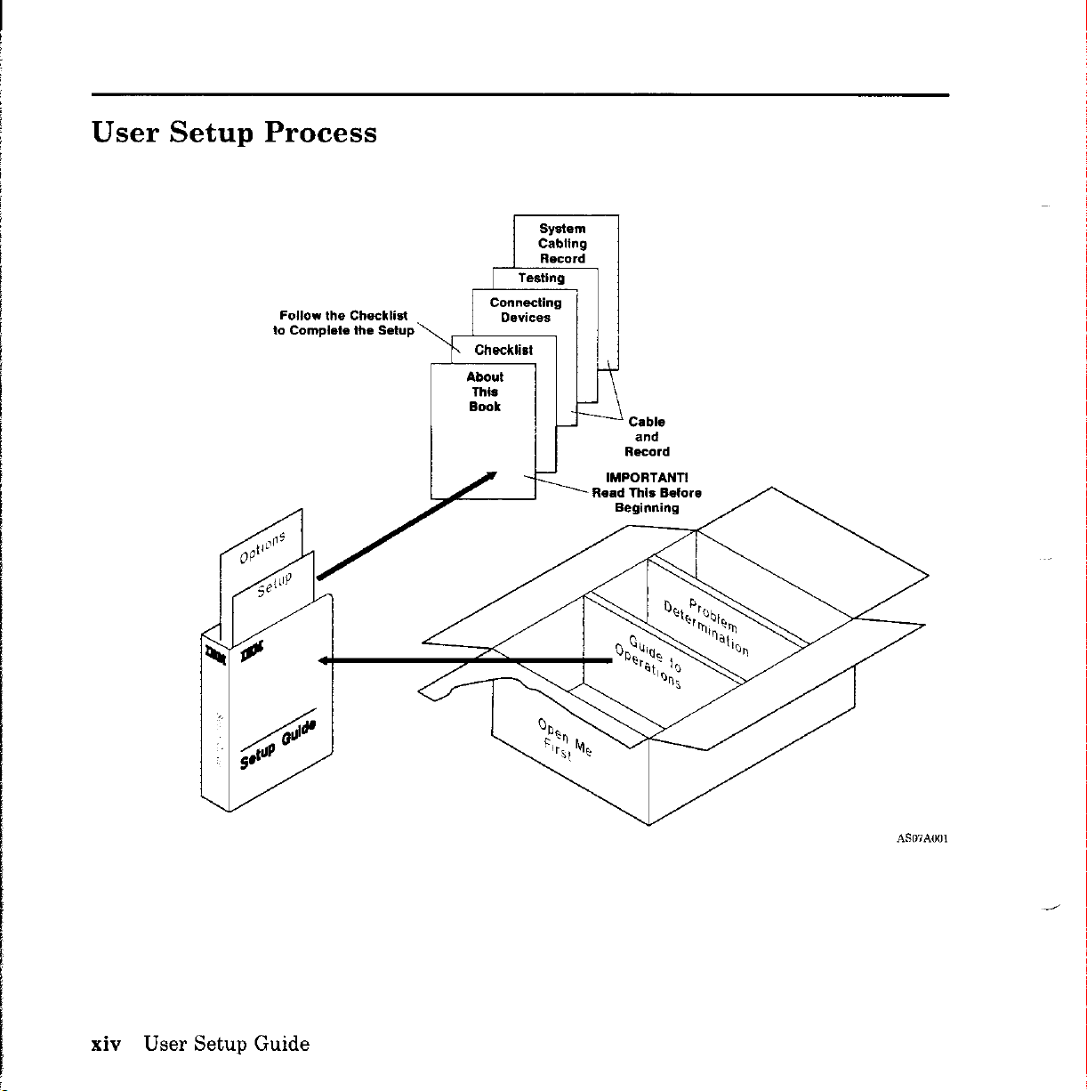
User
Setup
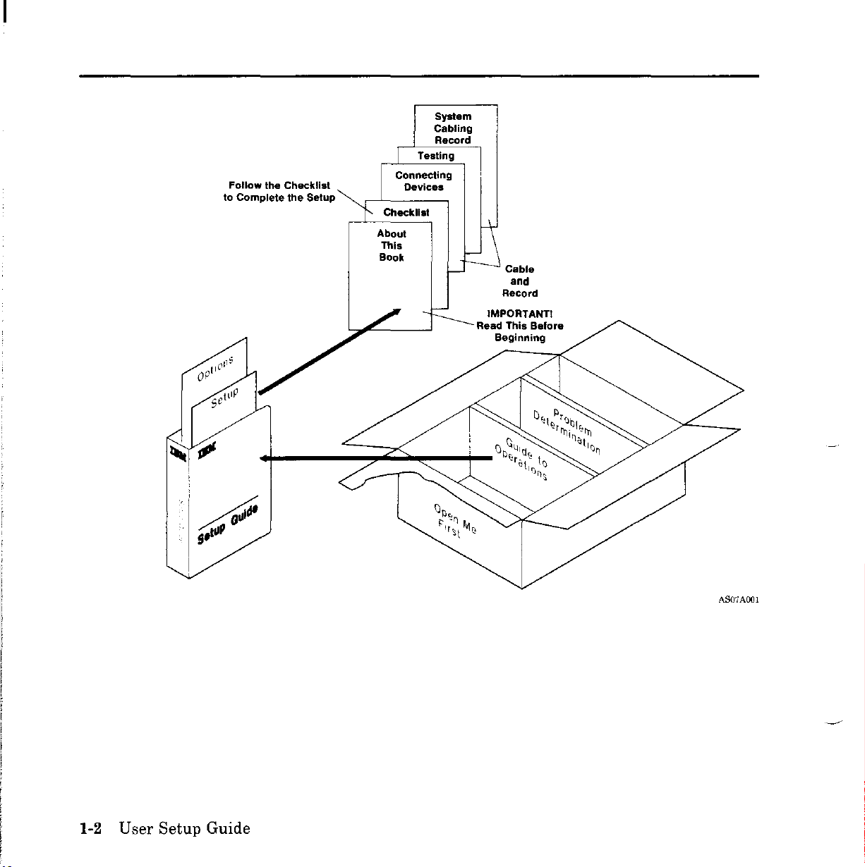
Process
Follow
the Checklist
to Complete the Setup'
Connecting
About
This
Book
Testing
Devices
System
Cabling
Record
Cable
and
Record
IMPORTANTI
Read
This
Beginning
Belore
xiv User Setup Guide
AS07AOOI
Page 15
IBM
RT
PC
User
up
the
IBM
RT
three
1.
2.
3.
To
of
•
•
•
basic
Identifying,
the
Testing
Installing
help
information:
Check
book)
Sections2and3of
typeofsetup)
Other
tasks:
system
the
you
set
listoftasks
books
the
Setup
Personal
unpacking,
unit
system
operating
up
the
.
(detailed
Guide
Computer®.
setup
IBM
(Section1,the
this
contains
and
connecting
system
RT
PC,
book
(supporting
information).
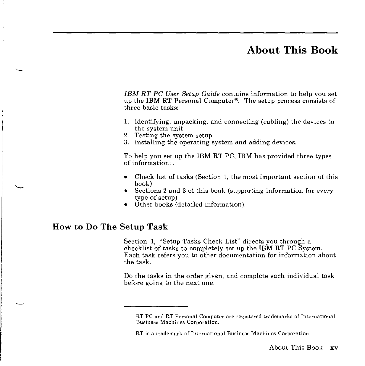
About
information
The
and
adding
IBM
most
setup
(cabling)
has
provided
important
information
This
to
process
the
devices.
help
consists
devices
three
section
for
Book
you
set
of
to
types
of
this
every
How
to
Do
The
Setup
Section
checklist
Each
the
task.
Do
the
before
RT PC
Business
RT
Task
1,
"Setup
of
tasks
task
refers
tasks
going
is
in
to
andRTPersonal
Machines
a trademark
Tasks
to
youtoother
the
the
of
Check
completely
order
next
one.
Computer are
Corporation.
International
List"
set
documentation
given,
and
Business
directs
up
the
complete
registered
Machines
you
through
IBM
RT
PC
for
information
each
individual
trademarksofInternational
Corporation
About
System.
This
a
about
Book
task
xv
Page 16
Section
contains
IBM-supported
adapters,
device.
The
devices.
to
the
book
system
2,
"Connecting
drawings
ports,
shows
Select
and
reference
devicestothe
connectors,
every
the
unit.
possible
instructions
This
Devicestothe
material
system
and
cables
setup
for
the
section
helps
IBM
to
units.
needed
situation
devices
you
do
RT
PC
help
you
The
section
to
connect
for
you
task6on
System
IBM-supported
need
Unit"
connect
shows
each
to
page
connect
1-6.
the
What
You
Need
Section
hardware
A
Reader's
provided
Formatany
book.
Evaluation
You
install
other
and
You
or
outlets
To
3,
After
can
the
information
two
flat-bladed
also
tables
for
begin
setup.
at
unpack,
need
on
the
"Testing
This
Comment
the
backofthis
timetogive
you
become
Form
operating
mostofthe
to
set
in
screwdrivers
sufficient
whichtoset
setup,
gototask1in
the
System"
section
Form
give
up,
system
this
devices.
helps
and
Book
book.
IBM
information
familiar
IBM
specific
connect
programs
book,
floor
up
other
spaceinwhich
the
contains
you
Evaluation
Use
the
with
the
feedback
devices,
using
referenced
(small
devices,
and
Section1of
the
do
task7on
Reader's
that
book,
test
medium).
and
steps
for
page
Form
Comment
may
improve
use
the
about
the
hardware,
the
check
documentation,
to
work,
grounded
this
book.
testing
1-7.
are
Book
the
book.
list,
the
sturdy
electrical
the
the
and
desks
xvi
User
Setup
Guide
Page 17
Related
Information
You
•
•
•
•
may
find
the
IBM
RT
PC
IBM
6150
system
devices
procedures
6151
IBM
System
customizing
or
characteristics.
or
IBM
installing
installing
with
IBM
for
problems.
high-capacity
diagnostic
and
RT
delete
change
RT
IBM
RT
running
that
for
IBM
PC
provides
the
devices
AIX
PC
optional
fixed-disk
RT
PC
diagnostic
A
routines
following
Guide to Operations
units,
can
be
operating
6150
Installing
stew
AIX M
from
This
and
Options
PC
User
books
the
attached.
the
system
units.
and
by-step
Operating
the
system
book
non-AIX
Installation
adapters
and
diskette
Setup
helpful:
describes
displays,
This
guide
hardware
Customizing
instructions
System,
and
also
explains
minidisks.
provides
in
IBM
6151
drivesinIBM
Guide).
keyboard,
and
howtodefine
Problem Determination Guide
problem
(1.2MB)
routines
determination
diskettes
are
included.
to
locate
guide
containing
the
IBM
6151
and
other
also
includes
moving
the
AIX
for
installing
including
howtocreate,
instructions
and
IBM
provides
and
for
the
the
Operating
6150
6150
identify
software
IBM
howtoadd
device
(packaged
instructions
RT
and
IBM
and
delete,
for
and
hardware
and
two
PC
See
IBM
RT
PC
Bibliography
of
IBM
RT
PC
publications
AIXisa trademarkofInternational
and
and
Master
diskettes.
Business
Index
Machines
About
for
order
Corporation.
This
Book
numbers
xvii
Page 18
Ordering
Additional
To
following
•
• To
Copies
order
To
SA23-2608.
additional
sources:
order
order
of
from
from
This
your
your
Book
copiesofthis
IBM
IBM
publication,
representative,
dealer,
use
part
use
use
Order
22F9802.
either
Number
of
the
A
binder
and
tabs
are
included
with
the
order.
xviii
User
Setup
Guide
Page 19
Contents
Section
Before
Setup
Tasks
Section
System
Before
Example
Preparing
System
Serial
Completing
Input
Display
Devices
IBM
IBM
IBM
IBM
IBM
System
IBM
System
IBM
System
IBM
System
IBM
IBM
Unit
IBM
IBM
Unit
IBM
Connected
1.
You
2.
You
Ports
RT
6150
RT
6151
5083
5083
5083
5083
5080
5080
5080
5080
(IBM
6155
Unit
Office
Unit
PC
PC
Unit
Unit
Unit
Unit
Setup
Start
Check
Tasks
List
Connecting
Start
Arrangements
the
Devices
Drawings
Sl
and
the
System
Keyboard
System
Keyboard
System
Tablet
Tablet
Tablet
Tablet
Lighted
Dials
Lighted
Dials
6155)
Extended
to
Unit
Unit
(Model11or
(Model11or
(Model
(Model
Program
Feature
Program
Feature
IBM
Check
Devices
S2
Cabling
and
IBM
and
IBM
12)
12)
11Aor12A)
11Aor12A)
Function
Connected
Function
Connected
Monochrome
6150
System
List
to
the
Record
RT
PC
RT
PC
Connected
Connected
Connected
Connected
Keyboard
to
Keyboard
to
Graphics
Unit
IBM
Mouse
Mouse
IBM
IBM
Display
RT
Connected
Connected
to
IBM
to
IBM
to
to
Feature
6150
System
Feature
6151
System
PC
6150
6151
IBM
IBM
1-1
1-3
1-5
2-1
2-3
2-3
2-4
2-5
2-6
2-6
2-7
to
2-7
to
2-7
2-8
2-8
6150
2-9
6151
2-9
and
2-10
and
2-10
2-11
2-11
Contents
xix
Page 20
IBM 6155
Connected
Display
IBM 6154
IBM 6150
IBM 6154
IBM 6151
Display
IBM 6153
Connected
IBM 6153
Connected
Display
IBM 5154
Connected
IBM 5154
Connected
Display
IBM 5151
6150
IBM 5151
6151
Display
IBM 5081
IBM 6150
IBM 5081
IBM 6151
IBM 5081
System
IBM 5081
System
IBM 5081
6150
IBM 5081
6151
IBM 6157
IBM 6157
System
IBM 6157
System
Serial
Serial
Printers
Plotters
Extended
to
Monochrome
IBM 6151
System
Graphics
Unit
Display
2-12
(IBM 6154) 2-13
Advanced
System
Advanced
System
Color
Unit
Color
Unit
Graphics
Graphics
Display
Display
Connected
Connected
to
2-13
to
2-14
(IBM 6153) 2-15
Advanced
to
Advanced
to
Monchrome
IBM 6150
Monchrome
IBM 6151
System
System
Graphics
Unit
Graphics
Unit
Display
2-15
Display
2-16
(IBM 5154) 2-17
Personal
to
Personal
to
Computer
IBM 6150
Computer
IBM 6151
Enhanced
System
Enhanced
System
Unit
Unit
Color
Color
Display
2-17
Display
2-18
(IBM 5151) 2-19
Personal
System
System
Unit
Personal
Unit
(IBM 5081)
Monochrome
System
Monochrome
System
Color
Unit
Color
Unit
Color
System
System
Streaming
Unit
Color
Unit
Streaming
Unit
Streaming
Unit
and
Computer
Computer
Unit
Unit
Display
Display
Display
Display
Tape
Tape
Tape
Plotters
Display
Display
Display
Display
(Model
(Model
(Model
(Model16or
Drive
Drive
Drive
(Model
(Model
12)
12)
16or19)
Connected
Connected
Connected
Connected
11)
Connected
11)
Connected
Connected
Connected
Connected
19)
Connected
to
to
to
IBM
to
IBM
to
to
to
IBM 6150
to
IBM 6151
to
to
IBM 6150
IBM 6151
2-19
2-20
2-21
2-22
2-22
2-23
2-23
IBM
2-24
IBM
2-24
2-25
2-25
2-26
2-27
2-29
xx
User
Setup
Guide
Page 21
Parallel
Terminals
Terminals
Terminals
Modems
IBM
Personal
IBM
3270
Ethernet
IBM
Token-Ring
IBM
5080/IBM
IBM
S/370
System
IBM
Megapel
IBM
RT
IBM
RT
IBM
6156
IBM
6156
connected
Printers
and
and
and
and
Autocall
Network
Network
Host
Display
PC
Small
PC
6192
Portable
Portable
to
Work
Work
Work
Computer
RT
Stations
Stations
Stations
Network
PC
Interface
Computer
Expansion
Disk
Disk
IBM
6150
(RS232C/MIL-STD 188)
(RS232C) 2-34
(RS422A)
Units
Network
Graphics
Adapter/IBM
Adapter
System
Unit
Drives
Drives-Model
and
6151
System
Interface
System
RT
PC
001
Graphics
(SCSI)
and
Units
_. . . . .
Adapter
003
2-30
2-31
2-37
2-38
2-43
2-44
2-45
2-46
..
2-47
2-48
2-49
2-50
2-51
2-52
2-52
-
Section
Before
Checking
You
Appendix
Purpose
Using
3.
Out
the
Testing
Start
the
A.
System
System
the
System
Cabling
System
Cabling
Record
Records
Contents
3-1
3-3
3-6
A-I
A-I
A-I
xxi
Page 22

xxii
User
Setup
Guide
Page 23
Section
1.
Setup
Tasks
Check
List
Section
1.
Setup
Tasks
Check
List
1-1
Page 24
Follow the Checklist
to Complete the Setup
System
Cabling
Record
Testing
Connecting
Devices
About
This
Book
Cable
and
Record
IMPORTANTl
Read This Before
Beginning
1-2
User
Setup
AS07AOOl
Guide
Page 25
Before
You
Start
To
the
process.
before
help
set
check
you
up
As
you
do
the
IBM
list.
The
you
gotothe
each
RT
PC
check
complete
next
task.
System,
list
guides
each
one.
task,
Use
you
must
you
through
writeacheck
the
referenced
complete
the
information
by
the
setup
the
tasks
task
on
to
Section
1.
Setup
Tasks
Check
List
1-3
Page 26
Notes:
1-4
User
Setup
Guide
Page 27
Setup
Tasks
Check
The
setup
List
tasks
are
as
follows:
1. Locate
These
display,
printers,
This
packing
2.
Unpack
modems,
the
ask
Leave
connect
task
3.
Unpack the system
graphics
location
behind
Note:
is
setup.
all
are
keyboard,
and
book
carton
and
following
instructions
youtotest
enough
them
6.
on
in
the
This
not
true,
Follow
Installation,
the devices
the
devices
so
referstoeach
set up
the
space
to
you
mouse,
On.
on
the
the
the
shipped
devices, dosonow.
behind
the
system
unit.
the
packing
which
unit
book
have
included
you
to
connect
assumes
them
the
instructions
will
connect
for
one
entire
system
device
device
printers,
instructions
plan
installed
in
logo.
with
each
the
unit
For
the
carton.
to
use
the
the
this
binder,toinstall
to
the
system
unit,
modem,
by
the
name
plotters,
device.
devicessothat
as
IBM
Unpack
it.
other
options
before
in
IBM
terminals,
on
the
instructed
6150,
the
Leave
devicestoit.
are
you
RT
system
setup,
terminals,
printed
packing
If
the
instructions
you
to
dosoin
follow
unit
enough
installed.
continue
PC
Options
the
unit.
such
as
on
the
and
cartons
can
the
near
the
space
If
this
with
options.
the
or
the
CONTINUE
TO
THE
NEXT
Section
PAGE
1.
Setup
Tasks
Check
List
1-5
Page 28
4.
Prepare for
•
Prepare
on
•
Familiarize
Unit
•
Read
Cabling
5.
Locate the appropriate system
Read
the
as
you
record
6.
Connect (cable)
the
instructions
the
IBM
following:
•
Beginat2-7
devices
•
Locate
devicesatthe
•
Identify
you
cabling
the
2-4.
Drawings"
the
instructions
Record"
instructions
do
task6,using
in
ordertodo
RT
PC
you
the
on
have.
by
system
yourself
on
the
devices to the system
on
2-7inSection2,"Connecting
System
and
do
not
device
topofthe
the
page
doing
units
with
2-5.
under
on
2-6.
and
record
Section
tasks7and
Unit"
work
have.
you
and
through
want
the
following:
using
the
system
"Completing
cabling
the
2.
in
this
the
to
connect
page.
in
the
"Preparing
by
record
requested
You
must
8.
unit,
book.
section,
in
system
unit
the
reading
the
System
in
Appendix
information
complete
beginning
Devices
Note
skipping
the
list
the
Devices"
"System
A.
this
with
to
the
of
connector
1-6
User
Setup
Guide
The
book
word
connector
IBM
6150orthe
are
printed
operation
match
until
•
Connect
showninthe
•
Complete
device.
You
adapters
It
is
corresponding
the
you
can
connect
as
important
shows
referstoeither
circuit
of
the
oneinthe
find
one
the
device
drawings.
the
system
devicestoany
wellasto
to
write
port
on
only
ports
cards
system
drawing,
that
using
cabling
any
the
the
the
IBM-supported
on
the
adapter
or
boards
unit).
matches.
the
cable
record
portofthe4-or
port
ofan8-port
device
system
cabling
Serial
brackets.
that
If
your
gotothe
(or
as
name
nexttothe
connectors.
Ports
connector
Sl
change
following
an
equivalent)
you
connect
cable
record.
8-port
The
and
S2
(Adapters
the
does
pages
each
assembly.
on
not
Page 29
This
book
connect
IBM-supported
7.
Test the system
book.
to
shows
the
all
the
system
devices.
using
IBM-supported
unit.
Section3,"Testing
Use
the
instructions
devices
the
you
System"inthis
for
can
only
With
and
(VRM)
8.
See
and
instructions
If
you
completed
representative
arrangement
following:
•
Use
system
•
Use
skipping
completion
can
and
Installing
Customizing
decidetoadd
system
Options Installation
unit.
this
now
on
can
of
both
check
tasks
of
task7,you
install
the
the
VRM
cabling
use
listtoconnect
that
the
AIX
Operating
Virtual
the
AIX
and
optionsordevices
record
the
record
the
old
do
not
have
Virtual
installed
Resource
System.
Resource Manager
Operating
AIX
Operating
to
to
and
new
to
install
the
apply.
System
in
the
the
point-of-purchase.
designacompatible
options.
the
new
new
devicestothe
Manager
and
for
complete
System
future,
Afterward,
options
the
system
Installing
installation.
take
the
The
do
the
in
the
system,
Section
1.
Setup
Tasks
Check
List
1-7
Page 30

1-8
User
Setup
Guide
Page 31
Section
2.
Connecting
Devices
to
the
IBM
RT PC
System
Unit
Section
2.
Connecting
Devices
2-1
Page 32
Follow the Checklist
to Complete the Setup
System
Cabling
Record
Testing
Connecting
Device.
About
This
Book
Cable
and
Record
IMPORTANTI
Read This Before
Beginning
2-2
User
Setup
AS07AOOl
Guide
Page 33

Before
You
Start
Use
Section1of
At
devices
this
any
sectiontodo
this
book.
point
you
in
have,
this
Setup
process,
return
Tasks2,4,5,and6on
to
when
the
you
check
have
list.
the
connected
check
all
the
list
in
Example
Office
Arrangements
IBM Pro-Prln..r
IBM
Pro~Prlnter
IBM AT PC Advanced
Monochrome Graphics
IBM
6'50
System Unit
Display
Mous.
IBM Streaming
Tape
-l'JJ<Y
IBM
RT PC Advanced
Monochrome Graphics
Display
Drive
Section
2.
Connecting
Devices
AS{}7AOO2
2-3
Page 34

Preparing
the
Devices
Prepare
following:
1.
For
IBM
remove
Remove
a.
Pull
b.
Lower
IBM
System Unit
2.
For
IBM
remove
The
rear
unit
the
system
6150
System
the
shipping
the
rear
the
bottomofthe
the
covertofree
6150
(Front)
6151
System
the
shipping
coverisinabox
carton.
Do
unit
cover:
not
for
connecting
Units,
card
(if
rear
Serial Number
Units,
card
(if
attached
put
the
devices
open
the
diskette
oneispresent),
the
open
cover
hooks
the
free.
from
diskette
oneispresent),
to
the
rear
cover
by
doing
drive
and
the
frame.
drive
and
insideofthe
on
until
the
lever,
close
the
lever,
close
the
system
toldtodo
lever.
AS07AOO3
lever.
so.
2-4
User
Setup
Guide
t:J
~
Serial Number
IBM
6151 System Unit
(front)
{Rear Cover}
AS07AOO4
Page 35

System
Unit
Drawings
The
following
containing
these
have,
devicestothe
drawings
the
connectors.
and
then
system
show
adapters.
Familiarize
gotoSetup
unit.
the
system
All
the
connections
yourself
Task5,Section1to
unit
with
connectors
you
make
the
system
begin
and
slots
willbeto
unit
you
connecting
Display
Power
System
Unit Power
Adapter_
Slots
.
Senal
Ports
Mouse
Keyboard
'-
[S1
52
o
]
(J
(J
Turn
to
IBM
6150
System Unit
the
off
the
system
power
unit.
B~~\=,
Display System
Power Power
..
on
all
devices
IBM
6151 System Unit
before
you
connect
Adapter
mm
==PR,=WUUU=~
Mouse Keyboard
I
Slot.
any
device
AS07A063
Section
2.
Connecting
Devices
2-5
Page 36

Serial
Ports
Sl
and
S2
On
IBM
interface
capability.
connect
your
system
DMA
6150
to
the
priority
System
provide
To
minimize
fastest
configuration
than
Units
Direct
serial
S2,
only,
Memory
impact
output
to
connect
on
devices
these
the
SI
overall
ports.
highest
and
S2
Access
(printers
use
the
(DMA)
system
Because
speed
RS232C
data
transmit
performance,
and
plotters)
SI
has
higher
devicetoS1.
in
Completing
the
System
Locate
AppendixA(Figures
and
read
device
or
devicesinthe
connected
Use
information
when
Section
Because
different
the
exact
beina
Someofthe
this
Use
identify
highlighted
Cabling
the
all
to
an
care
when
you
install
1).
each
arrangements
location
particular
case,
all
the
enlarged
the
appropriate
the
AppendixAinstructions.
adapter
the
keyboard
you
when
system
adapters
the
locations
adapter
Record
example
A-I
or
correct
complete
you
test
the
operating
unit
of
of
manyofthe
slot,
that
can
possible
drawings
of
slots.
and
through
port,
boxes.
and
the
can
the
slotishighlighted.
be
slots
to
the
adapters
A-4
write
mouse.
this
installed
the
Do
record,
system
system
contain
adapters,
adapters.
are
highlighted.
identify
not
blank
on
pages
name
record
because
(Setup
programs
different
this
in
more
the
by
looking
cabling
As
of
Task7,Section
book
When
adapters.
record
A-4
through
you
connect
the
adapter,
where
you
(Setup
adapters
cannot
the
than
one
onlyatthe
you
need
Task
adapter
slot.
Do
and
tell
not
in
A-9),
each
device,
this
you
try
1)
8,
In
and
must
to
2-6
User
Setup
Guide
Stop
here
and
gototask6on
1-6
on
the
check
list.
Page 37

Input
Devices
IBM RT PC
6150
IBM RT PC
6151
System
System
Keyboard
Unit
Note:
Keyboard
Unit
M KBD
•••
"C.J.:IJ
1r;;:;;J"i
and
Connect
and
IBM RT PC
AS07AOO6
IBM RT PC
the
M
keyboard
Mouse
before
Mouse
Connected
you
connect
Connected
the
to
IBM
mouse.
to
IBM
"
,\
,
AS07AOO7
Section
2.
Connecting
Devices
2-7
Page 38

IBM
Unit
5083
Tablet
(Model
f
"
11
9::
(lB
or
~
(Tablet)
o
12)
Connected
to
IBM
IBM
5083
Tablet Cable
Kit Option
6487586
6150
System
AS07AOO8
IBM
Unit
2-8
5083
User
Tablet
Setup
(Tablet)
It[@
Guide
(Model
M
KBD
•••
'<.J..Y.,
'\
~
11
or
12)
Connected
to
IBM
~!F/
6151
A'3---
System
IBM
5083
Tablet Cable
Kit Option
6487586
AS07AOO9
Page 39
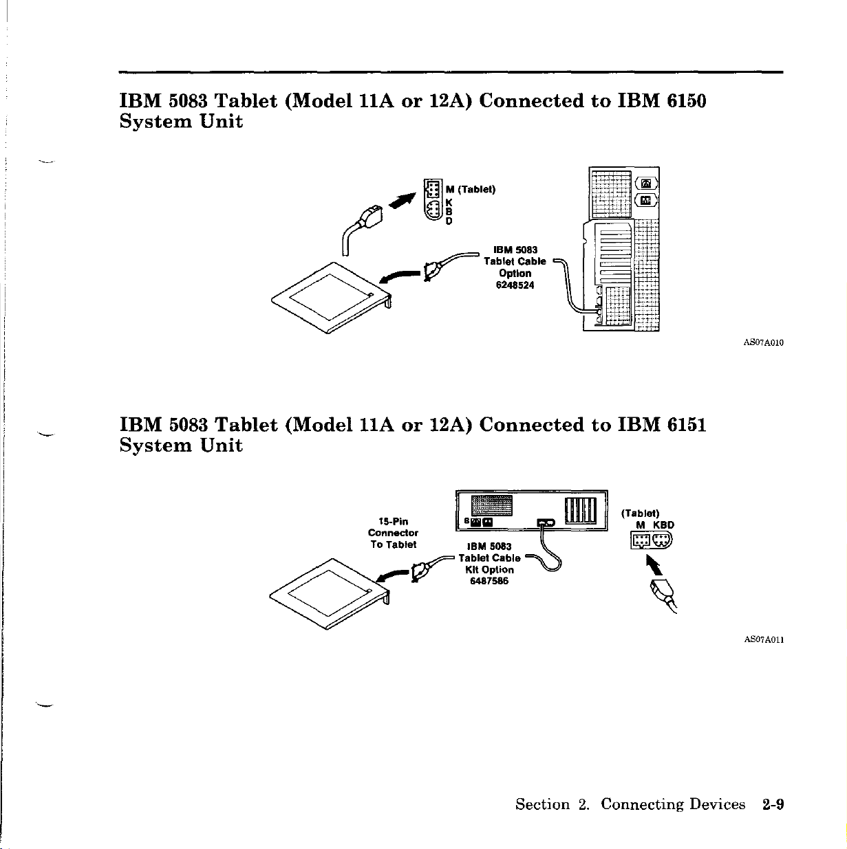
IBM
5083
System
Tablet
Unit
(Model
llA
1)
or
12A)
."
\{]:
Connected
(Tablet)
to
IBM
6150
(WB
IBM
5083
System
Tablet
Unit
~
~
(Model
((
D
~
,--
llA
15-Pln
Connector
To
J,;?"
or
12A)
Tablet IBM 5083
W
IBM
5083
Tablet Cable
Option
6248524
Connected
Tablet Cable
Kit Option
6487586
to
IBM
(Tablet'
M KBD
•••
10"7
\.
AS07AOIO
6151
'eM
~
AS07AOll
Section
2.
Connecting
Devices
2-9
Page 40

IBM
5080
5080
Dials
Lighted
Feature
Program
Connected
Function
to
IBM
Keyboard
6150
System
ISM
RT PC 5080 Peripheral Adapter
1()..Pln
Feature
Connector
Unit
and
IBM
IBM
5080
5080
Dials
Lighted
Feature
-"_.~
~
Program
Connected
Lighted Program Dials
...
~led
Function Keyboard
Program
Function
to
IBM
IBM 5080 Peripheral
Cable Kit Option
I
l!!llt:;~
Keyboard
6151
System
IBM RT PC 5080 Peripheral Adapter
IBM 5080 Peripheral
Cable Kit Option
6487564
6487564
Feature
1O-Pin
':>-
Unit
Connector
and
AS07A012
IBM
2-10
User
Setup
AS07A013
Guide
Page 41
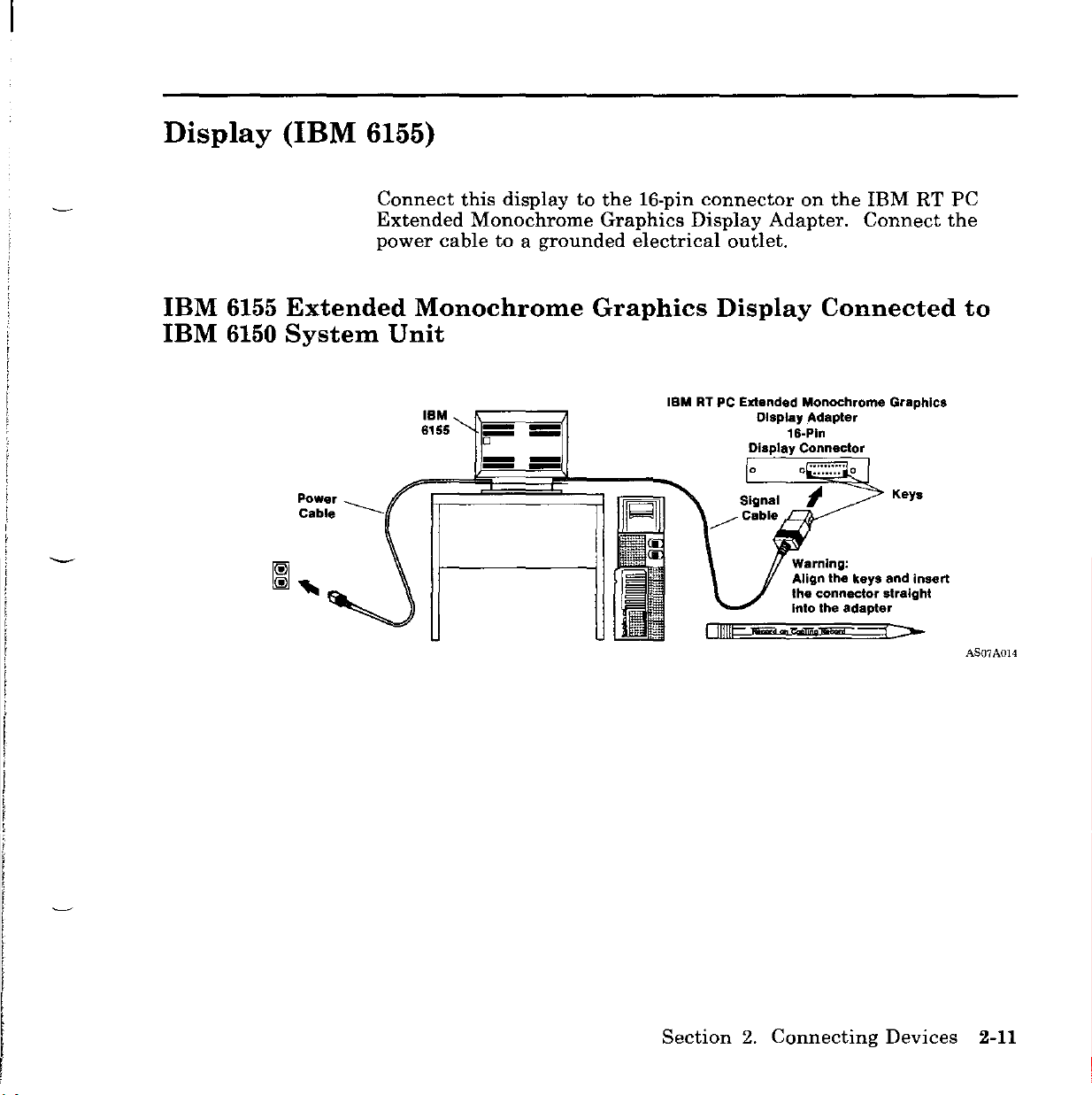
Display
(IBM
6155)
IBM
IBM
6155
6150
Extended
System
Power
_____
Cable
Connect
Extended
power
this
Monochrome
cabletoa
Monochrome
Unit
IBM
6155
displaytothe
grounded
-
1l""""
==
-
-
-
-
16-pin
Graphics
electrical
Graphics
IBMRTPC
connector
Display
outlet.
Display
Extended
Display Connector
I
IIlIlCJl¥¥i
on
the
Adapter.
Connect
Connected
Monochrome
Display
Adapler
16-Pln
Warning:
Align the keys and insert
the connector straight
Inlo the adapter
...
Nliije('fiFiiC
IBM
Graphics
Keys
j:>-
RT
PC
the
to
AS07A014
Section
2.
Connecting
Devices
2-11
Page 42

IBM
IBM
6155
6151
Extended
System
Monochrome
Unit
Graphics
Display
Connected
to
Power
Cable
IBM
6155
[I
JililmIlF~-~~~~""""""i!~_!;;!1!a~~i:::=-
--
--
--
--
Signal
Cable
IBMRTPC
Monochrome
Display
Extended
Graphics
Adapter
Keys
o
Display Connector
Warning:
Align
the
the connector straight
into the
adapter
16--Pln
keys
and
insert
AS07A0l5
2-12
User
Setup
Guide
Page 43
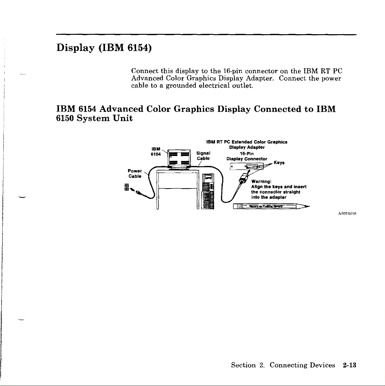
Display
(IBM 6154)
IBM
6150
6154
Advanced
System
Unit
Connect
Advanced
cabletoa
Color
Power
Cable
this
Color
grounded
Graphics
IBM.
r:;;;;;=~
6154
.......
displaytothe
Graphics
electrical
19M RT PC Extended Color Graphics
16-pin
Display
outlet.
Display
Display Adapter
16-Pln
Display Connector
o •
I
IIIII~~-..-.--
connector
Adapter.
on
Connect
Connected
.......
_.
Warning:
Align the keys and insert
the connector straight
into the
Keys
adapter
the
IBM
the
to
---r:::-
RT
power
IBM
PC
AS07A016
Section
2.
Connecting
Devices
2-13
Page 44

IBM
6151
6154
Advanced
System
Unit
Color
Graphics
Display
Connected
to
IBM
Power
Cable
IBM
6155
-
--
==
.!II
==
'"
UIID
Signal
Cable
IBMRTPC
Color
Display
111I11g;:_d~
Extended
Graphics
Adapter
Key.
o
Warning:
Align the keys
the
connector straight
Into
the
adapter
':>-
and
Insert
A&)7A017
2-14
User
Setup
Guide
Page 45

Display
(IBM
6153)
IBM
6153
IBM 6150
Connect
Advanced
power
not
a
Advanced
System
Unit
this
Monochrome
cabletothe
confuse
power
the
switch.
Monchrome
IBM
displaytothe
display
brightness
Graphics
RT PC Advanced Monochrome Graphics
Display Adapter
Display Connector
16-pin
Graphics
power
control
16-Pln
Warning:
Align
the connector straight
into
connector
Display
connector
on
Display
Key.
the
key.
the
adapter
Adapter.
on
the
frontofthe
and Insert
on
the
IBM
Connect
the
system
display
Connected
RT
unit.
PC
the
Do
with
to
AS07A018
Section
2.
Connecting
Devices
2-15
Page 46

IBM
IBM
6153
6151
Advanced
System
Power
Cable
Monchrome
Unit
IBM
6153
-
-
=
-
-
=
Graphics
IBM
RT PC Adavaneed
Monochrome Graphics
Display Adapter
Signal
Cable
•
Display
Key.
Warning:
Align the
the connector straight
Into the adapter
Connected
key.
and in8ert
to
A.."ID7A019
2-16
User
Setup
Guide
Page 47

Display
(IBM
5154)
You
can
easily
9-hole
Ensure
cabletoa
use
commercially
reach
connector
that
grounded
IBM
the
6150
on
the
display
electrical
available
System
IBM
power
extension
Units.
PC
switchisoff.
outlet.
Connect
Enhanced
cablestomore
this
displaytothe
Graphics
Connect
Adapter.
the
power
IBM
to
IBM
5154
6150
Personal
System
Power Cable
Extension
cable
Computer
Unit
IBM
5154
--rt-
JI
Enhanced
Signal Cable 9-Hole
Color
Enhanced Graphics Adapter
Display
IBM Personal Computer
Display Connector
p.-
.•
-01
Connected
AS07AOZO
Section
2.
Connecting
Devices
2-17
Page 48

IBM 5154
to
IBM 6151
Personal
System
Computer
Unit
Enhanced
Color
Display
Connected
~
::..wer
~
....;')\.
IBM 5154
Cable
'"
(.D=====~
\.\~~~~~b=:~~
Display Connector
B
..
iii
III
=
mm
lillJlIill
IBM Personal Computer
9~~~I~nced
Gr~~hIC.
Signal Cable
~
Adapter
ill
AS07A021
2-18
User
Setup
Guide
Page 49

Display
(IBM
5151)
The
IBM
The
system
You
easily
small
Printer
Connect
system
can
reach
9-hole
unit.
5151
unit
use
commercially
IBM
connector
Adapter
the
power
Personal
power
6150
or
on
cabletothe
Computer
switch
available
System
on
the
the
IBM
Display
turns
Units.
IBM
Monochrome
PC
Enhanced
display
has
this
display
extension
Connect
power
no
power
on
cablestomore
this
Display
Graphics
connector
switch.
or
off.
display
Adapter.
on
to
and
the
the
I
,
i
I
I
f
I
I
I
IBM
5151
System
Personal
Unit
Power
Cable
IBM
Computer
FD==~
5151
"""==;';;;;;:;;;~===dl~---.J
Display
Signal
Cable
Connected
IBM
Monochrome
and Printer Adapter
lo·~·'C·1
9-Hole"
Display
Connector
Extension Cables
Display
to
IBM
IBM
Personal
Enhanced Graphics Adapter
f'
Computer
-=.
0 ooj
9-Hole
Display
Connector
6150
AS07A022
Section
2.
Connecting
Devices
2-19
Page 50

IBM
5151
System
Personal
Unit
Computer
Power Cable
Display
IBM5151'{O~~~~=)
Connected
IBM Monochrome Display
and Printer Adapter
9-Hole
Display
Connector
to
IBM
IBM Personal Computer
Enhanced Graphics Adapter
6151
~
9:Holo
• Display
~
Connector
AS07A023
2-20
User
Setup
Guide
Page 51

Display
(IBM 5081)
•
For
the
interactive
into
color
RGB
the
displays,
video
display.
3-pin
connect
cabletomatching
Plug
connector
on
the
the
the
three
other
IBM
color-coded
input
receptacles
endofthe
Megapel
connectors
on
RGB
Display
the
video
Adapter.
on
cable
-
Note:
color-coded
interactive
Warning:
convenience
system
Ensure
power
outlet.
•
The
video
receptacle
RGB
Display
Note:
output
display.
Warning:
convenience
system
View-only
output
display.
Do
outlet
unit
will
that
the
cable,
monochrome
cable.
video
receptacle
firsttothe
This
on
the
cable
Adapter.
View-only
Do
outlet
unit
will
displays
receptacles
not
connect
on
be
damaged.
display
display
leadisconnected
interactive
into
displays
provided
not
connect
on
be
damaged.
the
power
display
the
the
can
back
uses
3-pin
may
on
back
be
connected
provided
IBM
5081
of
the
switchisoff.
and
then
only
the
to
display.
connector
be
the
IBM
Plug
connected
backofthe
5081
of
the
on
displays
IBM
to
green
the
matching
on
displays
IBM
to
three
the
backofthe
RT
Then
a
grounded
lead
the
other
the
IBM
to
the
interactive
RT
to
the
PC;
the
connect
on
the
input
endofthe
Megapel
greeen
to
the
PC;
the
the
wall
RGB
Ensure
power
that
the
cabletoa
display
grounded
power
wall
Section
switchisoff.
outlet.
2.
Connecting
Then
connect
Devices
the
2-21
Page 52

IBM 5081
System
Monochrome
Unit
IIIII
Display
(Model
11)
Connected
to
IBM 6150
Input Gain Output
IBM 5081
System
Green 0 2 4
Lead
-=:IJ
Switch
~
"
Monochrome
Unit
\ \ \ \ l I I I I I I I I I
Power
Cable
Extension
Cable
/I
"1
o
rrrrrrrrrrrrrrrr
Green
Lead
Display
o
(Model
rrrrrrrrrrrrrrrr
- Signal Cable
11)
Connected
~::_~~~y
3-Pin Megapel
Video
Connector Adapter
I
I
0\"::::::::::::/0
IBMDi::~pel
IBM
, Display
E::1
to
IBM 6151
I
I
AS07A024
2-22
User
~_~:_~n_O_._2_,
Input Gain Output
L
Setup
Guide
Switch
4_,
__
-----.J
~
~,o~;~~~r
~~i~tD~
~=~~6~~=:;:u;;;n;;';used;'=~=',:=~~~"
4
...
D
...
I
...
Leads
:::::.-
p,'ay
IA~l:":o;:·.:ptE:r
d:~~or
~
"",,-Signal
Cable
AS07A025
Page 53

IBM
Unit
5081
Color
Display
\
\\1
I
I,npul
(Model
" ,
~oo
02.
-=0
Gain
Switch
Output
ExtensiO~
Cable
12)
Connected
IfIIllllfIIllIIl
Power
Cable
to
IBM
o
6150
Connector " Adapter
System
IBM
Video Display
Megapel
i-a]
[o~:',;:,"""""""-;l
AS07A021i
IBM
Unit
5081
Color
Display
\\\\\\\
Input
t
(Model
I I
II
II
~oo
~
02.
-=rJ
Gain
Swilch
---=="---_~----.J
Output
12)
Connected
"'rf"'"rrr"'rf"'"rr"'rrf"'"[!"'"rf
Power
~"C.bl.
c5wr:!~~
Section
to
IBM
--,
~~:_~~~y
6151
System
IB~i~:~~pel
o Display Adapter
~Signal
Cable
2.
Connecting
Devices
\SOIAO:.l7
2-23
Page 54

IBM
5081
System
Color
Unit
Display
Gain
Power
Receptacle
Power 3-Pin
Cable i Video
II",
'..-1"1--+---11
Extension/
Cable
Switch
(Model
r=-+
Input
16
or
19)
Connected
Cables
Display10View-Only Display
__
Output
from Interactive
. connecto,ll
1 II1!1C-:-oo
Cji&!!jijnlii;prjl=
IBM
Megapel
Display
"Adapter
.~.
:
'::::J-
to
IBM
6150
.-\S07A028
IBM
5081
System
2-24
User
Color
Unit
Gain
Setup Guide
Display
Switch
Input
Power
Receptacle
~
"~~
~:~~:
n~.
I'iZiLl!
(Model
o
16
or
19)
Connected
Cables
o Display to View-Only Display
from Interactive
IBM
Megapel
to
IBM
6151
_~o",~i'~,
AS07A029
Page 55
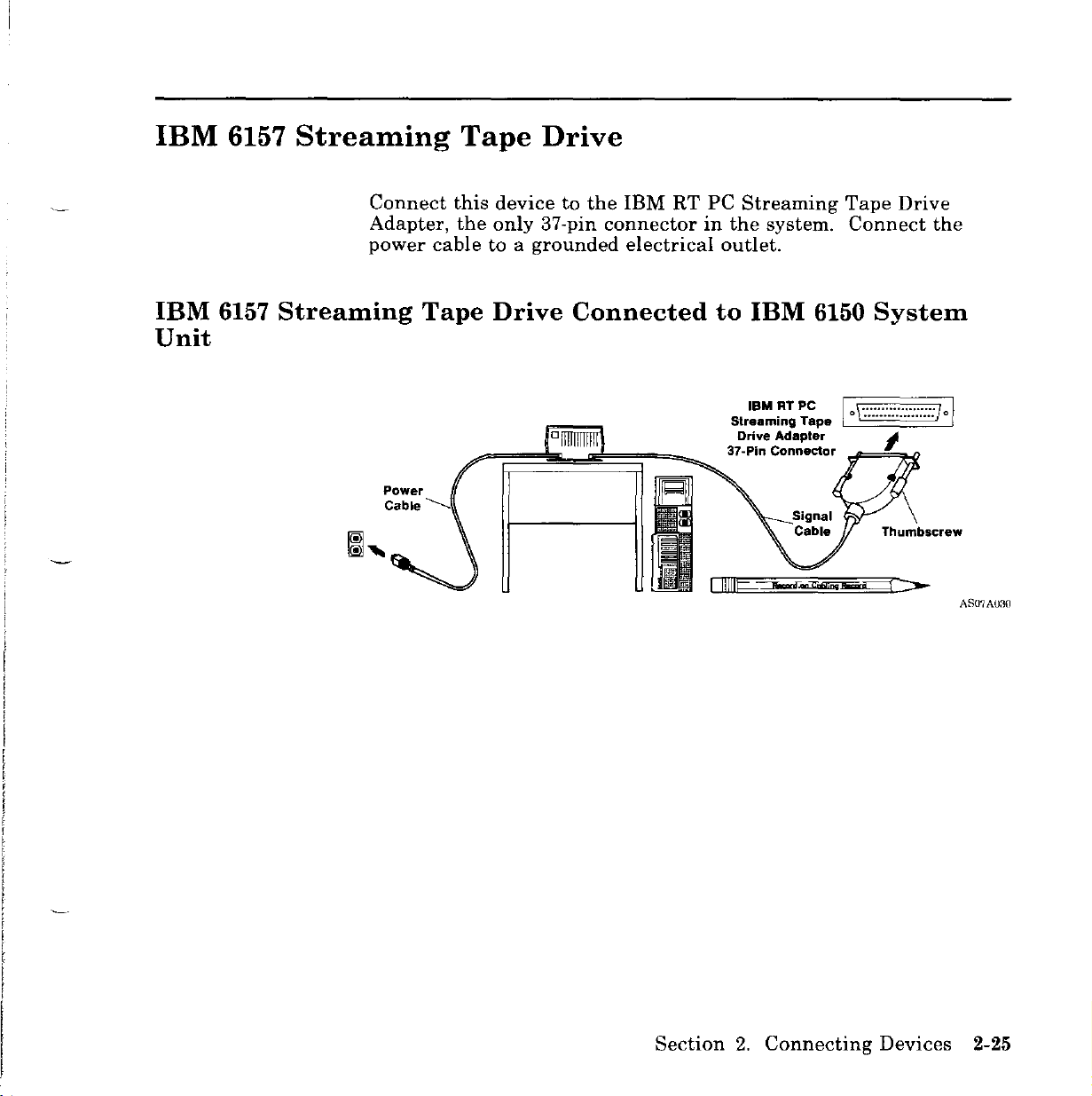
IBM 6157
Streaming
Tape
Drive
IBM
Unit
6157
Connect
Adapter,
power
Streaming
Power
Cable
this
the
cabletoa
Tape
..............
devicetothe
only
37-pin
grounded
Drive
Connected
IBM
RT
connector
electrical
PC
Streaming
in
the
system.
outlet.
to
IBM
IBMRTPC
Streaming
Drive Adapter ,
37-Pln Connector
Tape
Tape
Connect
6150
System
I \ /I
. 0 , 0 .
_==~
Drive
the
AS07A03{)
Section
2.
Connecting
Devices
2-25
Page 56

IBM
Unit
6157
Streaming
Tape
Drive
Connected
to
IBM
o.
ji Drive Adapter
6151
IBM
RTPC
Streaming Tape
System
Power
Cable
37·Pin
--
Signal
/Cable
Connecto
Thumbscrew--
~
Ii"
o
AS07A031
2-26 User
Setup
Guide
Page 57

Serial
Connecting:
I
II
I
Printers
•
IBM
3812
.
IBM
IBM
•
:
liE
• IBM
• IBM 7372 Plotter 79 Pins
•
IBM
• IBM 7375 Plotter
•
IBM
Pageprlnter
4201
Proprinte,
4202
Proprinter
liE
~~~~;;::~IS
7371
Plotter (RS 232C or MIL-STD 188)
7374 Plotter I
7375
Plotter
and
(with Asynchronous
Modell
Model
Plotters
XL (with Asynchronous
1 and 2
2
Interface
Interface
Feature
Feature
3000)
3000)
/iPort
IBM
6151
A.~:'::::::::d.Pllr
L .
To the
or Plotter
~cord
Otherserl.IPrin:::~
8-Port
Cable
(RS 232C/MIL-STD 188)
Option 08F3157
Printer
~
~==::ti
25 Pins
on Cabling Record
1
IBM
~#<~
~___
Assembly
Option 6294803
To
achieve
6150.
Use82for
Serial
';;:~:::
(3 m long)
optimum
~
j;:f
====ti
performance
connecting
~HOI'.
~~
~
from
anyofthe
high
other
speed
devices
printers,
listed.
:~
tf~
G
:::
IBM
Asynchronous RS 232C
lO-Pin Connectors
4
connect
printerstoconnector81of
6150
4 Ports
Adapter
1
--
23
10
Ports
Holes
AS07AO.12
the
Section
2.
Connecting
Devices
2-27
Page 58

Serial
Connecting:
Printers
•
•
•
•
•
•
•
•
•
•
•
L
•
and
IBM
3812
IBM
IBM
IBM
IBM
IBM
IBM
IBM
IBM
IBM
IBM
Other
Pageprlnter
4201
Propri"ter
4202
Proprl"ter
6180 Plotter
6184 Color Plotter
6186 Plotter
7371 Plotter
7372 Plotter
7374 Plotter
7375 Plotter
7375 Plotter
serial
Plotters
(with Asynchronous Interface
XL (with Asynchronous Interface
Models
Model
Model
printers
2
(Continued)
1 and 2
1
2
Feature
3000)
Feature
3000)
IBM
Personal
AT
SerialfParallel Adapter
10
0\0::::::::::::/0
Computer
9-Pln
Printer
Serial
Connector
9 Holes
L To the
2-28
User
Setup
or
Guide
Printer
Plotter
2
IBM
25 Pins
To
6150.
achieve
Use82for
optimum
perfonnance
connecting
from
anyofthe
high
other
speed
devices
Serial
Printer
Cable
Option 6298993
(3m
long)
printers,
listed.
connect
printerstoconnector81of
AS07A033
the
Page 59
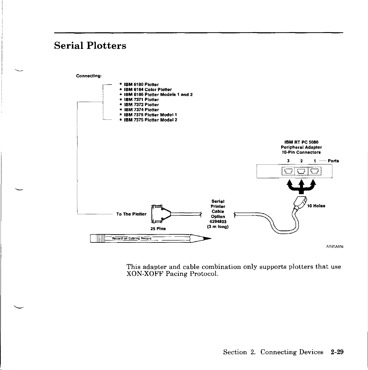
Serial
Connecting:
I-L
Plotters
•
IBM
6180
•
IBM
•
IBM
•
IBM
•
IBM
•
IBM
• IBM 7375 Plotter
• IBM 7375 Plotter Model 2
Ploner
6184 Color Plotter
6186 Plotter
7371 Plotter
7372 Plotter
7374 Plotter
Models
Modell
1 and 2
I
Serial
Printer
To The PloUer
This
XON-XOFF
D====~f
25 Pins
adapter
and
Pacing
cable
Protocol.
Cable
Option
6294803
(3 m long)
combination
only
supports
IBMRTPC
Peripheral
lo-Pin Connectors
3
plotters
5080
Adapter
2
1
-Ports
that
AS07AOM
use
Section
2.
Connecting
Devices
2-29
Page 60

Parallel
Connecting:
______
Printers
IBM
3852 Color Jetprlnter
•
•
IBM
4201 Proprioterdels 1 and 2
•
IBM
4202
5201
Propriote,
Printer
36 Pins
• IBM
• IBM 5201 Printer
• IBM 5152 Graphics Printer
• IBM 5182 Color Printer
To the Printer Cable
or Plotter Option
Modell
Model
~
XL
2
Printer
1525612
(l.S
IBM
m long)
IBM Monochrome Display
and Printer Adapter
25-Hole Parallel
Printer Connector
0
1
o~::::::::::::lo
25
Pins
25 Pins
ogJ
2-30
User
Setup
Guide
You
can
you
have
two
Personal
system
on
the
connectatotal
an
IBM
Monochrome
Computer
unit,
connect
Personal
Computer
the
of
two
parallel
Display
AT
Serial/Parallel
two
parallel
AT
Serial/Parallel
25-Hole Parallel
Printer Connector
IBM Personal Computer
AT
Serial/Parallel
devicestoa
and
Printer
Adapters
devicestothe
Adapters.
system
Adapter
installed
parallel
Adapter
unit.
and
ports
AS07A035
in
a
If
Page 61

Terminals
Connecting:
•
~
• IBM 3162 ASCII Display (3161 Mode Only) 8-Port Asynchronous Adapter
• IBM 3163 ASCII Display Station (3l61 Mode Only) (RS 232C or MIL-STD 188)
IBM
and
3161 ASCII
Work
Display
Stations
I 79 Pins
(RS232C/MIL-STD
!
",,,,,,,,,,,,,,,,""7
/
188)
I
Ports
a·port
Cable
(RS 232C/MIL-STD 188)
Option
L
To the Terminal Cable 1'\===='11
~
25
Pins Option 79X3913
Assembly
08F3157
~~
~
ASCII
T.,m/nal
RS
232C
(3m long)
c-r;10
Holes
~
~
S10
r9,"~S20
G
G
Asynchronous
1G-Pln
4 3 2
101010101
IBM
6150
4 Ports
RS 232C
Connectors
Adapter
1-Ports
Section
2.
Connecting
Devices
2-31
Page 62
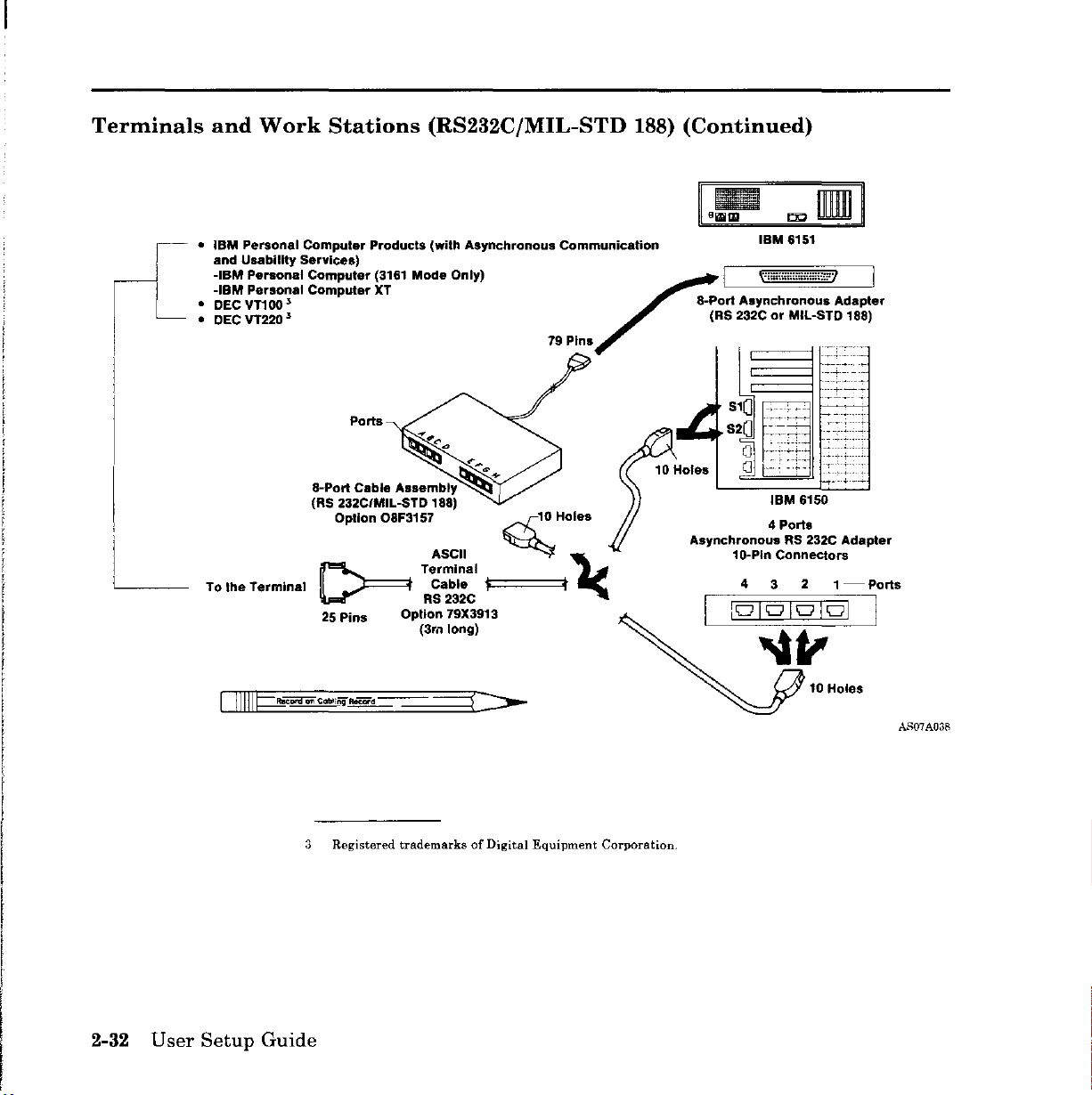
Terminals
and
Work
•
IBM
Personal
and Usability
-IBM
Personal
-IBM
Personal
• DEC
VT1oo.5
• DECVT220.5
To the
Terminal
Stations
Computer Products (with Asynchronous Communication
services)
Computer
Computer
8-Port
(RS 232CIMIL-STD 188)
(3161
XT
Ports
Cable
Option
~
25
Pins Option 79X3913
(RS232C/MIL-STD
Mode
Only)
Assembly
08F3157
~+
ASCII
TermInal
Cable
RS
232C
(3rll long)
c-r;10
~
'""===t'
f-
79 Pins
Holes
~
,
188)
~
(Continued)
IBM
6151
I
""""",,,,,,,,,,.,,.,
8-Port Asynchronous Adapter
(RS 232CorMIL-STD 188)
,
,.-
1
S
0
S20
-~:
o
o
till
IBM
6150
Asynchronous RS 232C Adapter
4 Ports
1o-Pln Connectors
4 3 2
1-Ports
101010101
I
2-32
User
Setup
Guide
3
Registered
trademarksofDigital
Equipment
AS07A038
Corporation.
Page 63
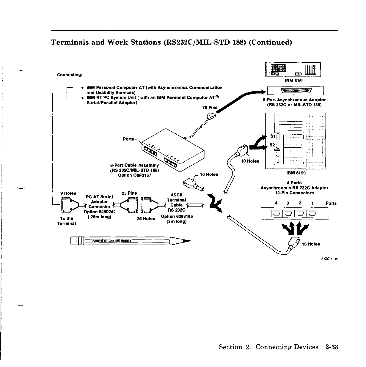
Terminals
Connecting:
and
Work
•
IBM
Personal
and
Usability
•
IBMRTPC
SeriallParallel Adapter) 79 Pins (RS 232C or MIL-STD 188)
System
Stations
ComputerAT(with
Services)
Unit ( withanIBM
(RS232C/MIL-STD
Asynchronous
Personal
Communication
Computer
AT ®
188)
(Continued)
IBM
6151
~
I X::::::::::::::::::::::::} I
8-Port
Asynchronous
r
.
Adapter
Ports
a-port
Cable
(RS 232C/MIL-STD 188)
i
L
9[::9HOles
To
the (.25m long) 25 Holes Option 6298186
Terminal (3m long)
PCA~~::~ial~2S
Connector Cable
Option 6450242
~O;Qra
Option
on Cabling Reeord
Assembly
08F3157 <Hoi
Pins
[::RT;~~~al
RS
232C
~
••
'2<
10
....
Holes
S10
S20
o
0,
Asynchronous
1G-Pin
4
IBM
6150
4 Porls
RS 232C
Connectors
2
3
10
Adapter
1 -
Holes
Ports
AS07AIJ40
Section
2.
Connecting
Devices
2-33
Page 64
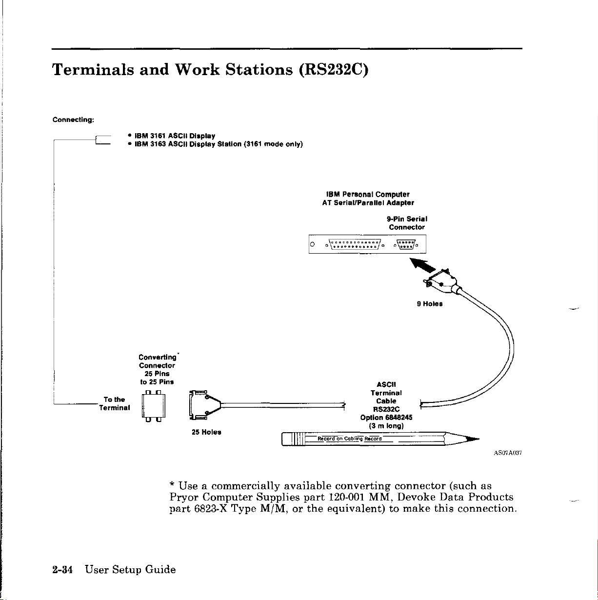
Terminals
Connecting:
•
•
and
IBM
IBM
Work
3161 ASCII Display
3163 ASCII Display Station (3161
Stations
mode
(RS232C)
only)
IBM Personal Computer
AT Serial/Parallel Adapter
10
0 \'::::::::::::70
9-Pin Serial
Connector
9 Holes
----Terminal
2-34
User
To the
Setup
Converting'
Connector
25
Pins
to 25 Pins
o
*
Pryor
part
Guide
D==~t
25
Holes
Useacommercially
Computer
6823-X
Type
~Ciii'iI""OrlCabling
available
Supplies
M/M,
or
part
the
Terminal
RS232C
Option 6848245
(3 m long)
Record
converting
120-001
MM,
equivalent)
ASCII
Cable
connector
to
Devoke
make
(such
Data
this
connection.
.'\807A037
as
Products
Page 65

Terminals
Connecting:
and
•
•
• DEY
Work
IBM
Personal Computer AT (with
Usability
·IBM
-IBM
DEY
VT100"
VT220"
Stations
Services)
Personal Computer
Personal Computer XT
(RS232C)
.synchronous
(Continued)
communications and
IBM
P.r80nal
SerlallParallel
AT
10
0
~::::::::::::I
Computer
Adapter
9-PI" Serial
Connector
0
9 Hates
ASCII
Terminal
Cable
RS232C
Option 6848245
(3 m long)
printers,
connect
2.
printerstoconnector81of
Connecting
Devices
AS07A039
the
2-35
L-
~
To the
Termine'
~
~~=========::ft
25 Holes
4
To
achieve
IBM 6150.
optimum
Use82for
performance
connecting
from
anyofthe
high
other
s~ed
devices listed.
Section
Page 66
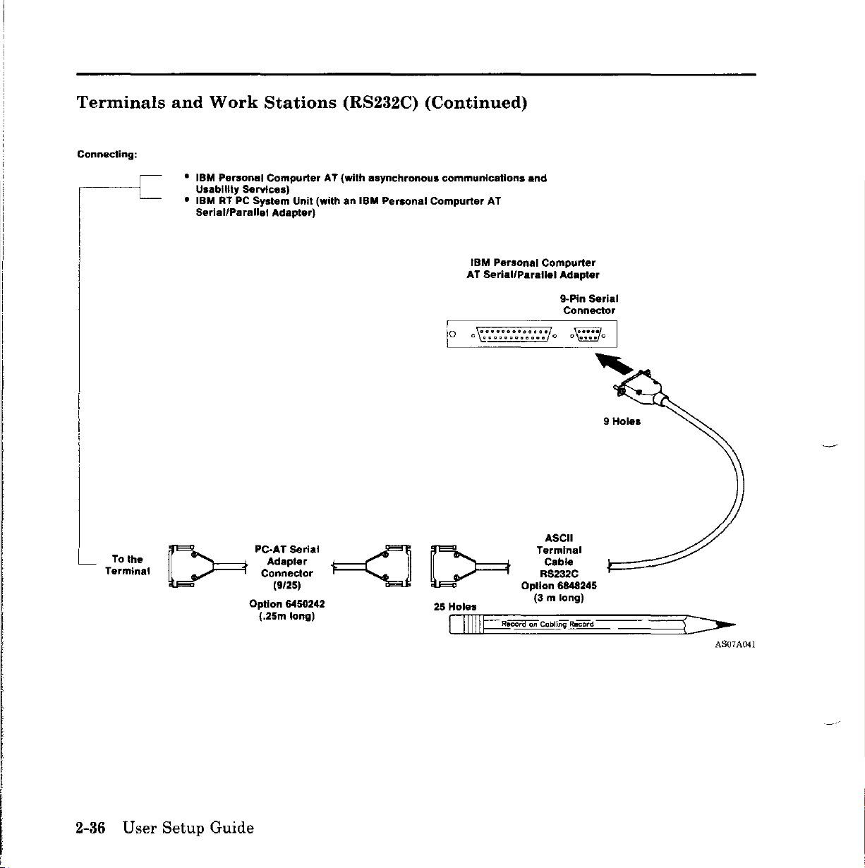
Terminals
Connecting:
and
Work
• IBM Personal Compurter AT (with asynchronous communications and
Usability
•
IBM
RT PC System
SeriallParallel Adapter)
Stations
services)
Unit
(withanIBM
(RS232C)
Personal
(Continued)
Compurter
AT
IBM
Personal Compurter
Serial/Parallel
AT
t."""""""""..";
a
••
g
•••••••••
Adapter
g..Pin Serial
Connector
0
9
Holes
L
2-36
Tothe
Terminal
[:::;==t
User Setup Guide
PC~:~~:;I'1
Connector
(9/25)
Option 6450242
(.25m
~ ~
long)
25 Holes
ASCII
Terminal
Cable
RS232C
Option 6848245
(3
m long)
CIIIIIJ=="i!cor'CIOiI
Cabling Record
AS07A041
Page 67

Terminals
Connecting:
IBM
IBM
IBM
and
3161 ASCII
3162
ASCII
3163 ASCII
8-Port
Work
Display
Display
Display
Ports
Cable
(RS 422A)
Stations
( 3161
Mode
Station (3161
Assembly
Only)
Mode
Only)
I OpUon 08F3158 c-/: 6
L
To
the
Terminal
==t'
D
=
25
Pins (20m long)
Terminal
'I
RS 422A r
Option 6294802
Option 6487641
(3m
ASCII
C.ble
long)
~
<<-====,
(RS422A)
Hoi
••
,
'I
8-Port
Asynchronous
(RS 422A)
4
6-Pln
Ports
Connectors
24 3
Asynchronous RS 422A
Adapter
Adapler
1 -
Ports
CIIIIIpcord
on
Cabli"9
Reeord
•
If
are
protection.
• Do
the
longer
not
cables
install
from
than
122 m (399 ft),
these
the
4-Port
cables
RS422A
you
outdoors.
Section
Adapter
must
provide
2.
Connecting
to
this
surge
Devices
AS07A042
terminal
2-37
Page 68

Modems
Connecting:
•
and
Modems
Autocall
The
RT
PCisdesignedtosupport
comply
Consultative
in
Book),
1969).
of
using
with
the
reportofthe
Geneva,
Additionally,
auto-dialer
asynchronous
Units
the
International
Committee
CCITT
10-21
modems
Telegraph
recommendations
Seventh
November
the
RT
PCisdesignedtosupport
that
conformtothe
attachment
Plenary
1980,
and
of
modems
and
Telephone
V.24/V.28,aspublished
Assembly (Yellow
EIA
RS232C
Hayes
AT
protocol.
I
\'''''''''''''''''''','''7
8-Port
79 Pins (RS 232C or MIL-$TD 188)
Asynchronous
~
I
that
(August
attachment
command
Adapter
set,
I
2-38
8-Port
(R5
232C/MIL-STD 188)
Option
Tolhe
Modem
[JIIIH==.i!CDTd
User
Setup
On
Cabling Record
Guide
Ports
Cable
Assembly
08F3157
51
0
...
52
0
(]
(]
AsynchronousRS232C
1O-Pin Connectors
4321-Ports
4
Ports
10
Adapter
Holes
AS07A043
Page 69

Modems
and
Autocall
Units
(Continued)
Connecting:
Modems
o
IBM
Personal
AT Serial Parallel Adapter
25--Hole
Parallel
Connector
0000000000000
o
000000000000
Computer
g..Pln
Connector
0
Serial
IBM PC-AT
com~~~~ations
Option 6450217
(3 m long)
f~=======::j
25 Pins
c::]
To
The
Modem
Section
2.
Connecting
Devices
.-\807A044
2-39
Page 70

Modems
and
Autocall
Units
(Continued)
Connecting: Modems
IBM
Munlprotocol Adapter
16-Pln
Connections
RTPC
Connection
14-Pin
IBM
RS2332C
Modem
Option 6294812
(3m
RTPC
Cable
long)
25 Pins
1t===:==::::::jc::J To The
Modem
2-40
User
Setup Guide
AS07A045
Page 71

Modems
and
Autocall
Units
(Continued)
Connecting:
Modems
IBM
Multlprotocol
16-Pln
Connections
RT PC
Adapter
14-Pln
Connection
IBM
RTPC
X.21
Modem
Option 6294816
mlong)
(3
Cable
15
Pins
~f==========C]
To The
Modem
D.[pcora
Section
on
Cabling
Reeord
2.
Connecting
Devices
AS07A046
2-41
Page 72

Modems
and
Autocall
Units
(Continued)
Connecting: Aulaeall Unit
o
IBM
Multlprotocol Adapter
l6-Pln
Connections
RTPC
I::::::::II::::::::
14-Pln
Connection
11:::::::1
Option 6294814
0
IBM
RTPC
Aulaesll
Unit
Cable
(3 m long)
25 Pins
i=t
=======:c:::J
To The
Modem
2-42
User
Setup
AS07A047
Guide
Page 73

IBM
Personal
Computer
Network
Connecting:
IBM
RT PC
You
devices
IBM
For
Network
the
Network Short,
System
can
using
PC
more
IBM
connect
Network
information,
Transformer
PC
Warning:
not
useatool.
Unit
this
the
IBM PC
cable
Base
Expander,
Medium
Tighten
systemtoa
Network
kit.
see
Setup
and
Translation
and
and
Long
the
connector
networkofcommunicating
Adapter
Instructions
Unit,
Setup
Distance Kits.
with
and
the
appropriate
for
the
IBM
Setup
Instructions
only
I 8
Instructions
for
the
your
IBM PC Network Adapter
fingers.
L.
PC
IBM
for
PC
Do
---'
TO:
IBM
PC Network
Section
2.
Connecting
AS07A048
Devices 2-43
Page 74

IBM
3270
Network
Connecting:
IBM RT
You
IBM
appropriate
Display
TO:
PC
can
Personal
IBM
3270 Network
System
connect
coaxial
System
Unit
this
systemtoan
Computer
Installation
3278/79
cableasdescribed
IBM
3270
Emulation
in
Adapter
IBM
Manual-Physical
IBM
Personal Computer 3278179
Emuulation Adapter
network
3270
Planning.
using
and
the
the
Information
AS07A049
2-44
User
Setup
Guide
Page 75
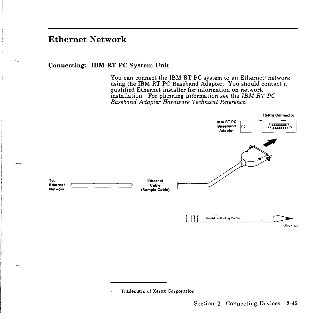
Ethernet
Network
Connecting:
To:
Ethernet
Network
ir::=========4{
IBM
RT PC
You
using
qualified
installation.
System
can
the
connect
IBM
Ethernet
For
Unit
the
RT
PC
installer
planning
IBM
RT
Baseband
information
PC
systemtoan
Adapter.
for
information
see
You
on
the
Baseband Adapter Hardware Technical Reference.
IBM
RTPC
Baseband 0
Adapter C
Ethernet
Cable
(Sample Cable)
Ethernetlnetwork
should
contact
a
network
IBM
RT
PC
15-Pln Connector
--=-~==__=_J
TrademarkofXerox Corporation
Section
2.
Connecting
Devices
AS07A050
2-45
Page 76

IBM
Token-Ring
Network
Connecting:
IBM RT
You
devices
the
If
cableasshowninthe
If
3
Token-Ring
GA27-3714.
PC
System
can
using
appropriate
your
system
your
system
Media
Filter
Unit
connect
this
systemtoa
the
IBM
Token-Ring
IBM
Token-Ring
uses
the
IBM
following
uses
telephone,
to
the
IBM
Token-Ring
Network Telephone Twisted-Pair Media Guide,
network
Network
Network
cabling
twisted-pair
system,
figure.
IBM
of
communicating
RT
PC
adapter
connect
media,
Network.
Token-Ring Network
RT PC Adapter
connect
See
Adapter
cable.
the
IBM
and
adapter
the
Type
g..Pln Connector
••.••
o
••••
0
I
To' 0
IBM
Token-Ring
Network
2-46
User
--------:....
~
Setup
~
i
Guide
IBM
==~J
Network Adapter
-.:r
PIN 6339088
(2.44m long)
Token Ring
Cable
~==~
)-
AS07A051
Page 77
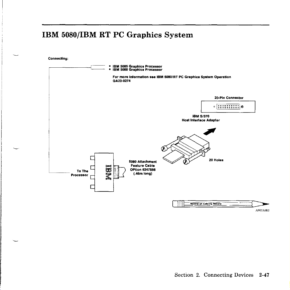
IBM
Connecting:
L
5080/IBM
ToTh.
Processor
RT
PC
•
IBM
• IBM 5088
For
GA23-Q274
Ill! 00
-
1
11ti1Pl
0
;:li~1
Graphics
5085
Graphics
Graphics
more
Inlormation
5080
Attachment
Feature
Option
(.46m
Processor
Processor
see
Cable
6247856
long)
System
IBM 5080/RT
PC
Graphics
Host
System
IBM
$/370
Interface
Operation
20-Pln
o
Adapter
Connector
000000000"
I"""..""""""
I"
Section
2.
Connecting
Devices
AS07A052
2-47
Page 78
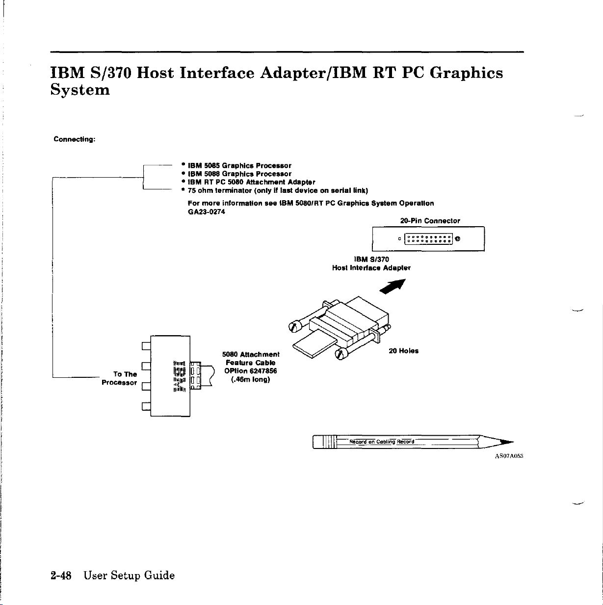
IBM
S/370
Host
System
Connecting:
,-------c
Interface
•
IBM
5085
• ISM 5088
•
IBMRTPC 5080
• 75
For
GA23-0274
Graphics
Graphics
ohm
terminator
more
information
5080 AUaehment
Feature
Option
(.46m
Adapter/IBM
Processor
Processor
Attachment
(onlyiflast
Cable
6247856
long)
see
Adapter
deviceonserial
IBM
5080/RT PC
Graphics
Interface
Host
link)
IBM
RT
System
51370
Adapter
PC
Graphics
Operation
20-Pin
Connector
o I::::::::::I@
2-48 User
Setup
Guide
DIIIIJ==.iicora
on Cabling Record
AS07A053
Page 79
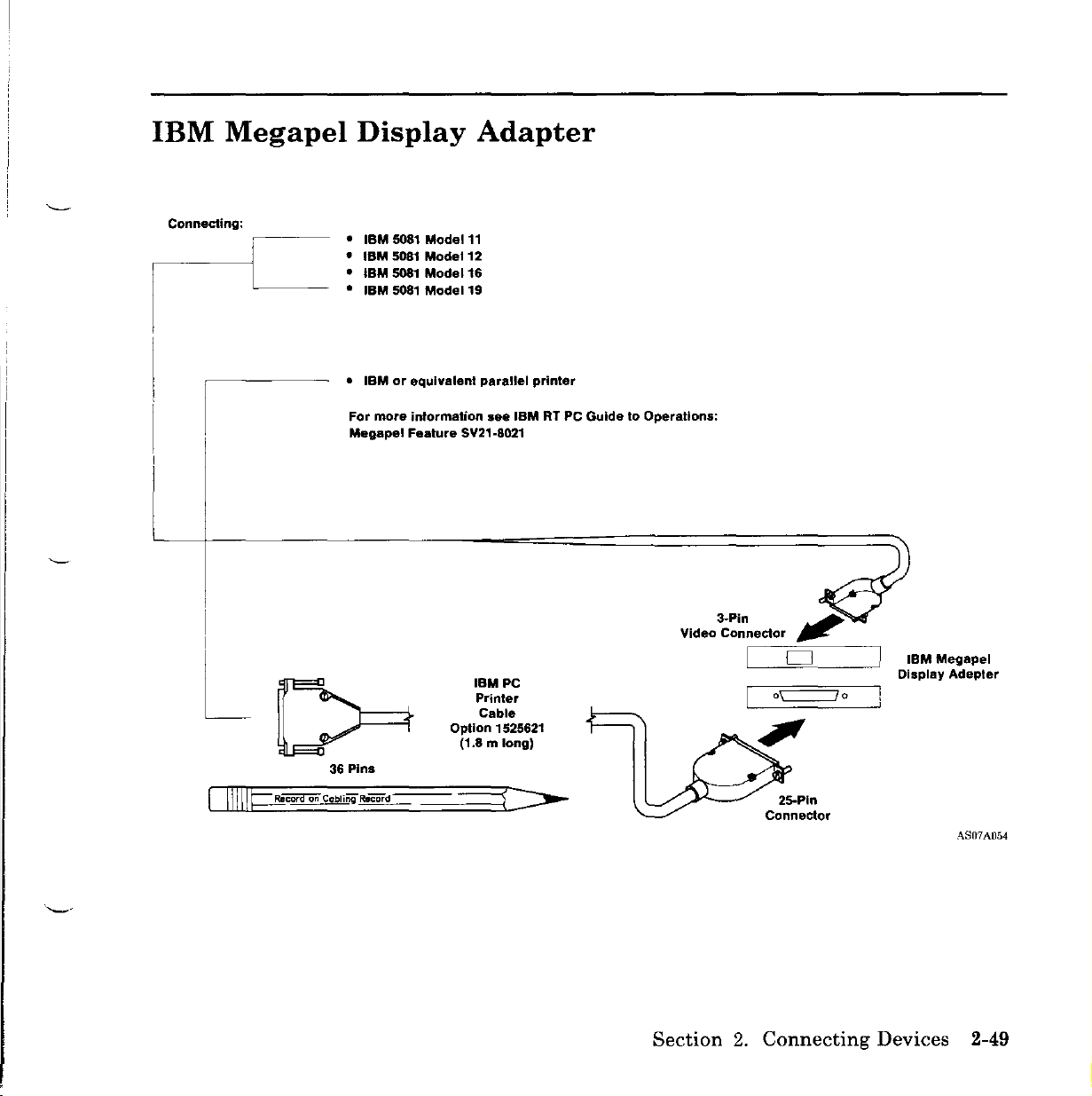
IBM
Megapel
Display
Adapter
Connecting:
CJIIIIpcord
~--
•
IBM
•
IBM
•
IBM
•
IBM
IBMorequivalent
•
For
more
Megapel
36
Pins
on
Cobli~
Record
5081
Model
5081
Model
5081
Model
5081
Model
information
Feature
11
12
16
19
parallel
see
SY21-8021
Option 1525621
(1.8 m
IBM
IBMPe
Printer
Cable
long)
printer
RT PC
GuidetoOperations:
Video
3-Pin
Connector
c----==---,
25-Pln
Connector
IBM
Display
Megapel
Adepter
A807A054
Section
2.
Connecting
Devices
2-49
Page 80

IBM
RT
PC
Adapter
Connecting:upto7devices
Small
Computer
System
Interface
(SCSI)
Terminating
(Option
79X3468)
Option 79X3468
(8 m
long)
Plug
IBM
Device
7
50
Pins
_~~:U:P:'O:4:m:or:.~~~~~~~~~~~~~~~~~~~";';'~~~~~
~
~
IBM
Devices
IBM
System
IBM
L-....tr----'
SO
Small
Compurter
Interface
Adapter
Device
Pins
(SCSI)
2
Option 79X3470
(1mlong)
~
IBM
Device
~
1
2-50
AS07A055
User Setup Guide
Page 81

IBM
RT PC 6192
Expansion
Unit
Connecting:
IBM
6192 Expansion Unit
RT
PC
Expansion
,~
,~
,
Unit
Receiver Card
, 0
Adapter
(Slot 7)
....................
~·""""·"""·"l
.•...............
Expansion Unit
Signal Cable
AJZH'211
Section
2.
Connecting
Devices
2-51
Page 82

IBM
6156
Portable
Disk
Drives
IBM
IBM
6156
6150
Portable
and
6151
Model
Connect
Adapter.
Disk
System
003
these
Drives
Units
devicestothe
-
Model
rtl
Ul
"
Portable
Disk Drive
IBM
001
•••••••••••••••••
••••••••••••••••
RT
and
PC
Portable
003
62
Pin
Connector
Disk
Drive
connected
~~~.
';:::~~:
••c••
00
.,_
00
•
IBM 6150
to
2-52
User
IBM Portable Disk Drive Module
You
have
list.
Setup
Guide
completed
Setup
Model
001
Task6on
page
1-6;
IBM
6151
return
to
the
AJZIF212
check
Page 83

Section
3.
Testing
the
System
Section
3.
Testing
the
System
3-1
Page 84

Follow the Checklist
to Complete
the
Setup
System
Cabling
Record
Teeling
Connecting
Devices
About
This
Book
Cable
and
Record
IMPORTANTI
Read This Before
Beginning
3-2 User Setup Guide
ASOiAOOl
Page 85

Before
You
Start
Use
problems,
CAUTION
this
section
go
to
with
IBM
task
RT
7.
If
the
system
PC
Problem Determination Guide.
has
operational
Before
unit
and
and
device
"Safety
1.
Ensure
unit.
2.
Connect
the
rearofthe
devicetothe
CONTINUE
doing
all
Notice
the
the
any
procedure,
connected
power
cables
Translations"
powerisoff
system
system
power
TO
THE
devices,
from
on
all
unit
power
unit.
connector
NEXT
turn
and
electrical
on
page
devices,
cabletothe
Connect
on
the
PAGE
off
power
unplug
iii.
including
the
power
device.
to
system
outlets.
the
power
cable
the
system
unit
Refer
system
connector
for
each
to
on
'-
Section
3.
Testing
the
System
3-3
Page 86

3.
Install
the
rear
cover.
• On
can
Warning:
an
place.
minimum
system
furniture
the
IBM
fit
the
rear
extended
It
is
clearance
unit
to
6150
system unit,
coverinplace.
Do
not
operate
period
of
time
recommended
be
provided
cover
ensure
louvers
adequate
arrange
the
without
that
and
cooling.
the
cables so
IBM
6150
the
rear
75
mm(3inches)
between
adjacent
walls
system
cover
the
IBM
or
that
unit
in
6150
you
for
3-4 User Setup Guide
AS07A056
Page 87

•
On
Slide
a.
Insert
Push
b.
c.
Insert
cover.
the
the
IBM
cables
the
down
the
6151
lower
on
clips
system
into
hooks
the
on
unit,
the
slotsinthe
into
back
the
system
do
the
cover.
not
remove
cover.
holesinthe
unit
into
the
the
frame.
loops
cables.
on
the
Warning:
minimum
system
obstructions
CONTINUE
It
clearance
unit
TO
is
recommended
cover
THE
louvers
to
ensure
NEXT PAGE
be
provided
adequate
and
that
75
between
adjacent
cooling.
mm(3inches)
the
IBM
6151
walls
or
AS07A057
Section
3.
Testing
the
System 3-5
Page 88

CAUTION
Checking
Out
Devices
safety.
outlets
Notice
4.
Connect
5.
Goto"Checking
the
1.
Get
cover
2.
Unlock
3.
If
4.
Open
5.
Turn
system
Close
have
Plug
to
Translations
System
Diagnostic
of
the
notch
the
the
unit
the
all
avoid
all
IBM
the
system
diskette
power
and
drive.
electrical
devices
possible
on
the
power
Out
Diskette
RT
PC
unit
on
the
disketteiscovered
drive
switches
immediately
cables
only
electrical
page
cablestogrounded
the
System,"
1 (DIAG-1) from
Problem Determination Guide.
by
(the
on
and
into
iii.
turning
top
driveinIBM
for
all
insert
plugs
grounded
shock.
electrical
below.
the
the
key
by a
devices,
the
diskette
designed
electrical
Refer
pocketinthe
counterclockwise.
tab,
remove
6150).
including
(label
for
to
Safety
outlets.
the
the
side
back
tab.
up).
3-6
User
Setup
Guide
CONTINUE
TO
THE
NEXT
PAGE
Page 89

6.
Is
the
green
power·on
tt(Y\
~~
1111111111111111111111111111111111111111
1111111111111111111111111111111111111111
light
ri'
on?
11
~
q
L.SJ
AS07A058
Yes.
No.
7.
After
flash
CONTINUE
Gotothe
Check
the
light
on
and
next
all
the
comes
offonthe
TO
THE
step.
electrical
on,
wait
two-digit
NEXT
PAGE
cables
several
display.
and
outlet.
minutes
while
numbers
Section
3.
Testing
the
System
3-7
Page 90
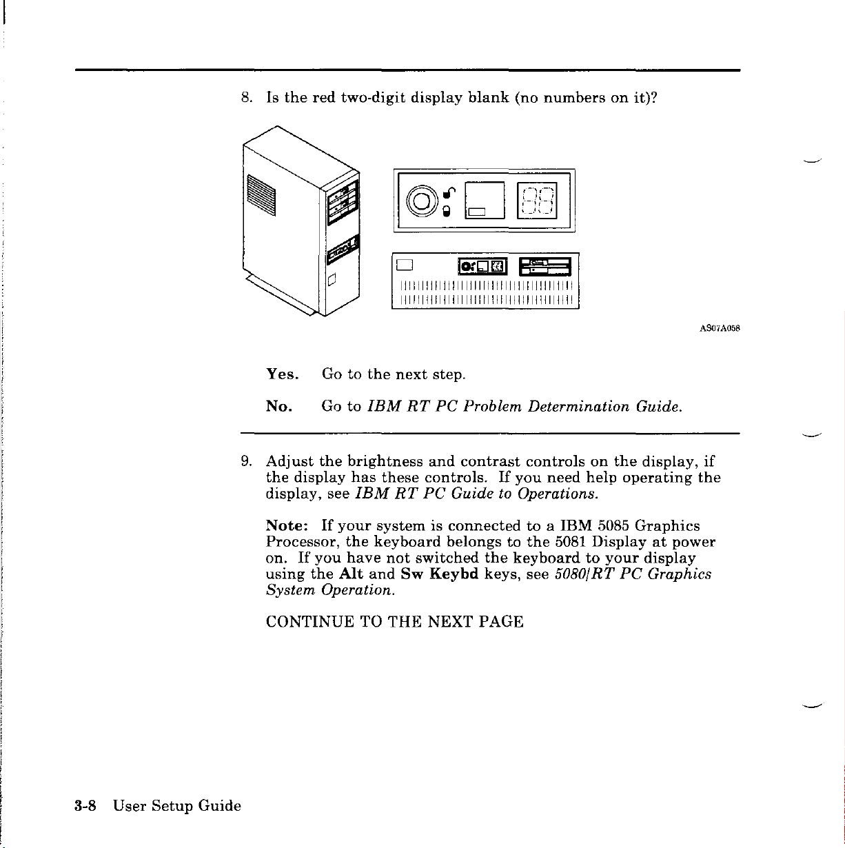
8.
Is
the
red
two-digit
display
1111111111111111111111111111111111111111
1111111111111111111111111111111111111111
blank
(no
numbers
on
it)?
AS07A058
Yes.
No.
9.
Adjust
the
display,
Note:
Processor,
on.Ifyou
using
System
CONTINUE
Gotothe
Go
the
display
see
If
the
Operation.
next
to
IBM
RT
brightness
has
these
IBM
your
systemisconnected
the
keyboard
have
not
Art
and
TO
RT
Sw
THE
and
controls.
PC
switched
Keybd
NEXT
step.
PC
Problem Determination Guide.
contrast
If
you
controls
need
on
help
Guide to Operations.
toaIBM
belongstothe
the
keyboardtoyour
keys,
see
5081
5080/RT
5085
Displayatpower
PAGE
the
display,
operating
Graphics
display
PC
Graphics
if
the
3-8
User
Setup
Guide
Page 91
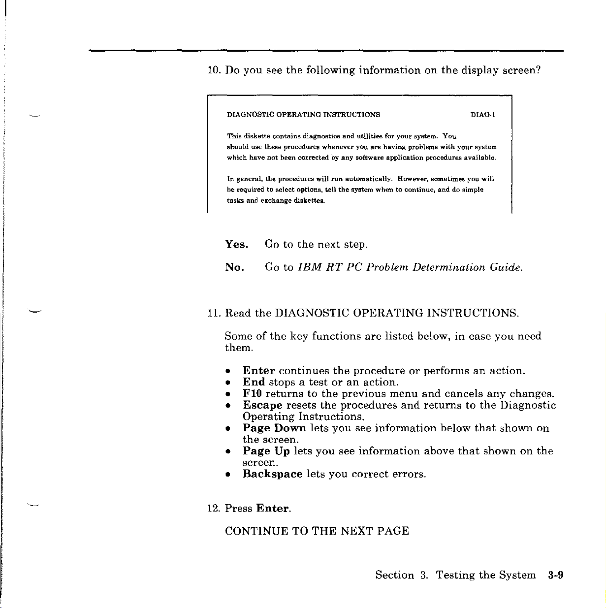
10.
Do
you
see
the
following
information
on
the
display
screen?
DIAGNOSTIC OPERATING INSTRUCTIONS
This
diskette
should
which
In
general,
be
requiredtoselect
tasks
Yes.
No.
11.
Read
Someofthe
use
these
have
the
and
exchange
Gotothe
Go
the
contains
not
diagnostics
procedures
been
procedures
whenever
correctedbyany
will
run
options,
tell
diskettes.
next
to
IBM
RT
DIAGNOSTIC
key
functions
them.
•
Enter
•
End
•
FlO
•
Escape
Operating
•
Page
the
Page
•
continues
stopsatest
returns
resets
Instructions.
Down
SCreen.
Up
lets
to
lets
or
the
the
you
you
screen.
•
Backspace
lets
you
and
utilities
you
are
software
automatically.
the
system
step.
PC
Problem Determination Guide.
OPERATING
are
the
procedure
an
action.
previous
procedures
see
see
information
correct
for
your
system.
having
problems
application
whentocontinue.
procedures
However, sometimes
INSTRUCTIONS.
listed
below,incase
or
performs
menu
and
and
returns
information
above
errors.
You
with
your
and
do simple
cancels
below
that
DIAG-l
system
available.
you
will
an
any
to
the
that
shown
you
need
action.
changes.
Diagnostic
shown
on
on
the
12.
Press
CONTINUE
Enter.
TO
THE
NEXT
PAGE
Section
3.
Testing
the
System
3-9
Page 92

13.
Do
you
FUNCTION SELECTION
In
ITEM
1
Diagnostic
This
selection
detennineifyou
by
a SRN (Service Request Number). The SRN will allow your service
representative to quickly determine what parts are requiredtorepair
see
the
Routines
allows
following
you to
have
a hardware problem. Any problem
information
test
your machine's hardware and
on
the
will
be indicated
screen?
Yes.
No.
14.
Type4to
typewriter
This
15.
Do
INSTALLED OPTIONS LIST
The
ADAPTERfDEVICE
Processor and Memory Management Card
2MB Memory Expansion Option
Yes.
Gotothe
Go
to
select
key
process
you
see
the
following options are installed on your machine.
Gotothe
next
IBM
Installation
area.
may
take
INSTALLED
next
RT
step.
PC
not
several
step.
Problem Determination Guide.
Verification.
the
numeric
Use
keypad.
the4on
Press
minutes.
OPTIONS
SLOT ADDRESS
A
LIST?
DIAG-l
!!ill
DMA
c
the
Enter.
3-10
User
Setup
Guide
No.
Go
CONTINUE
to
IBM
TO
RT
THE
PC
Problem Determination Guide.
NEXT
PAGE
Page 93

16.
Compare
cabling
system
adapters
slot
the
the
INSTALLED
record
unit
on
you
(task6and
the
system
numbersofthe
slot
numbers
completed
adapters
match?
OPTIONS
Section
cabling
when
on
2).
The
record
the
LIST
with
connecting
slot
numbers
should
Installed
the
system
devicestothe
of
be
the
sameasthe
Options
List.
the
Do
Yes.
No.
17.Ifyou
Gotothe
Call
the
that
the
have
a 4or8-Port
next
person
two
lists
step.
who
installed
do
not
Asynchronous
(RS232C/MIL-STD 188/RS422A)oran
AT"
Serial/Parallel
additional
Lookatthe
after
the
name.
system
similar
cabling
to
pieceofinformation
adapter
the
following:
Adapter
Write
record.
names
this
The
on
number
information
ADAPTER/DEVICE
Personal
Personal
4-Port
4-Port
4-Port
4-Port
The
the
primary
alternate (2)
second,inslot4;the
Computer
Computer
Asynchronous
Asynchronous
Asynchronous
Asynchronous
numbers
immediately
(1)
isinslot
AT
Serial/Parallel
AT
Serial/Parallel
RS-232C
RS-232C
RS-422A
RS-422A
after
Serial/Parallel
6.
The
third,
in
the
match.
IBM
installed,
on
the
the
screen
in
Adapter
Adapter
Adapter
Adapter
the
adapter
Adapterisin
first
4-port
slot7;and
options
Adapter
Personal
you
needtonote
system
the
and
on
ID
your
cabling
note
column
Adapter
Adapter
1
2
3
4
names
slot3,and
adapterisin
the
fourth,
and
screen
1
2
report
Computer
one
record.
the
number
on
the
looks
SLOT
mean
the
slot2;the
in
slot
3
6
2
4
7
8
that
8.
AnXmay
adapter
are
CONTINUE
appear
set
TO
after
the
incorrectly.
THE
NEXT
adapter
PAGE
Section
nameifthe
3.
Testing
switches
the
System
on
the
3-11
Page 94
18.
Lookatthe
cabling
Write
6150
slots
cabling
these
19.
Remove
the
only
and
not
numbered
pocketinthe
adapter
record
the
slots1through5in
listed
record
the
diagnostic
Determination Guide.
You
have
completed
names
the
namesofadapters
namesofadapters
on
the
should
adapter
back
task
on
cabling
match
slots.
diskette
cover
7.
Return
IBM
the
of
the
screen.
you
in
slots2through8in
6151. Do
record.
information
from
the
IBM
RT
to
the
have
The
drive
PC
check
Write
completed
not
on
On
not
worry
the
and
Problem
list.
the
system
yet
recorded.
IBM
about
system
screen
returnitto
for
3-12
User
Setup
Guide
Page 95
Purpose
Appendix
The
system
the
devices
device.
information
when
Carefully
you
install
cabling
and
the
when
A.
record
adapter
complete
you
test
the
operating
System
providesaplacetorecord
or
porttowhich
this
record.
the
system
system
Cabling
you
You
must
(Setup
(setup
Task7,Section1)and
Task8,Section
connected
Records
the
names
have
this
of
each
1).
Using
the
System
Cabling
Study
1.
2.
3.
the
Record
each
As
you
number
printed
where
If
more
the
name
Write
corresponding
made
•
Slots
for
adapters
Personal
Record
appropriate
the
cabling
devicetothe
connect
the
in
the
than
as
the
nameofeach
the
connection.
that
recording
(cable)
adapterisin.
Section
adapterisinstalled.
one
adapter
many
to
the
can
device
with
two
Computer
sample
information
system
2)inthe
times
contain4or
record,
unit.
each
Write
space
of
the
as
necessary.
connected
adapter
names.
connectors
AT®orthe
and
then
immediately
devicetoan
the
adapter
corresponding
same
typeisinstalled,
device
connector
8-port
Slots
or
IBM
adapters
that
ports
do
the
following:
after
you
adapter,
on
(port)towhich
can
(for
Monochrome
name
to
the
line
have
contain
example,
note
(asitis
the
eight
cable
the
slot
slot
record
you
lines
only
the
Display
IBM
Appendix
A.
System
Cabling
Records
A-I
Page 96

and
Printer
names.
If
the
under
the
Devices
Unit,"
to
the
IBM
the
and
6192
Adapter)
RT
PC
Name
column
column,
then
record
Expansion
have
two
Expansion
as
record
the
Unit.
lines
Unit
you
would
"IBM
adapters
for
recording
Adapterisused,
any
other
RT
PC
6192
Expansion
and
devices
device
record
adapter.
that
relate
it
In
4.
Disregard
oneortwo
•
Record
system,
where
The
ID
between
of
the
only
you
you
column
adapters
cabling
the
extra
ports.
the
might
connect
under
of
record
lines
on
the
devices
not
the
you
connect.
write
in
keyboard
formifthe
all
the
and
mouse.
adapter
Depending
spaces.
Do
Adaptersisprovidedtodistinguish
the
same
when
type.
you
test
You
will
complete
the
systeminSection
on
not
has
your
this
only
record
part
3.
A-2
User
Setup
Guide
Page 97

You
must
you
leave
depends
complete
Section
on
the
the
following
2.
The
information
IMPORTANT
System
success
on
of
this
the
form.
Cabling
system
Record
setup
before
process
Appendix
A.
System
Cabling
Records A-3
Page 98

Name
SIol2T
~
~
~~
5101 3 I :PC.A3
J.,;d./5'<Vw1l.i
~
5101
4 I
353m:pc
~
~
5101
5 I 353m
J~Y",..
Dow.~
I
Figure
A~1
IBM 6150 System Cabling Record
Adapters
1I:r
:PC
Connectors
(Ports)
10
1
2
3
4
5
,6
,7
8
J.,;d.
1
5'<Vw1l.i
2
11
2
3 i I
4 T
'5
6
~~t>
8
~
1~
'2
3
4
5
6
7
, 8
5'.4
5'.4
~
V
~~~
3fJJm 4201
I 353m 5201
i
'/CV1
I/-';W
~("l
K"'\.l0'\
353m
~
I
,
Devices
(6153)
~
ow"""'-
,/
~0\
-,/
y_
~)
Dow.
I
I
I
I
I
Adapter
Slots
Serial
Ports S2
--I
S1
I
I
~'-
AS07A059
A-4 User
Setup
Guide
Page 99

I
Slot
SIol7
SIol8
Figure
Adepter.
Connectors
Name
6 I
fPC.J.:r
Jw..//fAv..lJ.l
~
I
4-5'...l
~
~232C
I
~
~422"<
A-1
(Cont.) IBM 6150 System Cabling Record
~
Sl
S2
(Ports)
10
Jw../5'...l
1
fAv..lJ.l
2
1
2
3
•
5 \
6
7
8
C"l
~
\)
f
•
5
6
7
18
J5dm4207~
J5dm
7371~
5W,
v
("\
~
J!Bm 3163
J!Bm5182C
J!Bm
~
Q
~\
~
Fm
Devices
.,uCJJ
....
3161
.,uCJJ
"
/.-Y
"'/-
~""/
"'"/"
"
3161
.,uCJJ
"
"
"
"
"
"
J
~
JInJi...
~
~
JInJi...
~
JInJi...
Adapter
~
I
I
_I
Slots I
Serial
Ports
L
Sl
$2
AS07A071
Appendix
A.
System
Cabling
Records
A-5
Page 100

Adapters
Connectors
Name
Slot
2l
Slot
3 I
Slot
4 I
Slot
5-1
Figure A-2 IBM 6150 System Cabling Record
(Ports)
10
1
2
3
4
5
6
7
8
1
2
1
2
3
4
5
6
7
8
1
2
3
4
;5
6
7
8
Devices
I
I
Adapta,
Slots
-[
,
Serial
S1
Ports
82
A807A070
A-6
User
Setup
Guide
 Loading...