

Page 1

RS/6000 Enterprise Server Model H80
Eserver pSeries 660 Models 6H0 and 6H1
Service Guide
SA38-0566-03
IBM
Page 2

Fourth Edition (April 2002)
Before using this information and the product it supports, read the information in “Safety Notices” on page xi,
Appendix A, “Environmental Notices” on page 493, and Appendix B, “Notices” on page 495.
A reader’s comment form is provided at the back of this publication. If the form has been removed, address comments
to Information Development, Department H6DS-905-6C006, 11501 Burnet Road, Austin, Texas 78758-3493. To send
comments electronically, use this commercial internet address: aix6kpub@austin.ibm.com. Any information that you
supply may be used without incurring any obligation to you.
© International Business Machines Corporation 2000, 2002. All rights reserved.
Note to U.S. Government Users -- Documentation related to restricted rights -- Use, duplication or disclosure is subject
to restrictions set forth in GSA ADP Schedule Contract with IBM Corp.
Page 3

Contents
Safety Notices ........................xi
Rack Safety Instructions .....................xi
Electrical Safety .......................xii
Laser Safety Information ....................xiii
Laser Compliance......................xiii
Data Integrity and Verification ..................xv
About This Book ......................xvii
ISO 9000 .........................xvii
Online Publications ......................xvii
Related Publications......................xvii
Trademarks ........................xviii
Chapter 1. Reference Information .................1
Overview ..........................1
Data Flow with One-Way Processor .................3
Data Flow with Two- to Six-Way Processor ...............4
Powering the System On and Off ..................4
Console Strategy .......................5
Power-On Self-Test.......................6
POST Indicators........................6
POST Keys .........................6
1Key..........................7
5Key..........................7
6Key..........................7
8Key..........................7
System Unit Locations......................8
CEC Drawer Front View ....................9
CEC Drawer Top View ....................10
CEC Drawer Rear View ....................11
Primary I/O Drawer Front View .................12
Primary I/O Drawer Top View ..................12
Primary I/O Drawer Rear View .................14
Primary I/O Drawer Front View with Covers Removed..........15
Secondary I/O Drawer Front View ................16
Secondary I/O Drawer Top View .................16
Secondary I/O Drawer Rear View ................18
PCI Board Locations .....................19
System Board Locations ...................20
Memory Riser Card and Memory DIMM Locations ...........21
One-Way Processor Card Memory DIMM Locations ..........22
Primary I/O Drawer Operator Panel ................23
Secondary I/O Drawer Operator Panel ...............24
SCSI IDs and Bay Locations ..................25
System Memory .......................26
One-Way Processor Memory Placement Rules ............26
iii
Page 4

Riser Card Memory Placement Rules ...............26
I/O Drawer Features ......................27
I/O Drawer Addressing ....................27
I/O Drawer and Power Supply LED Status..............28
Message Hierarchy for Secondary I/O Drawer Operator Panel .......29
Primary I/O Drawer Operator Panel Behavior During Power-On.......30
Secondary I/O Drawer Operator Panel Behavior During Power-On......31
Logical and Physical Locations ..................32
Physical Location Codes ....................32
Location Code Format ....................32
Multiple FRU Callout Instructions .................33
AIX Location Codes ......................34
AIX and Physical Location Code Reference Tables ...........36
Cabling the CEC Drawer, Primary I/O Drawer, and Secondary I/O Drawer ....48
Connecting JTAG and VS COM Cables ..............48
Connecting RIO and SPCN Cables ................49
System Cable Diagrams.....................54
CEC Drawer Cable Diagram ..................54
Primary I/O Drawer Cable Diagram ................55
Secondary I/O Drawer Cable Diagram ...............56
DC Power Cable Routings ...................57
Specifications ........................58
CEC Drawer .......................58
7014 Model T00 and T42 Rack .................60
I/O Drawer ........................62
Noise Emission Notes....................64
System Service Clearances ..................65
Power Cables ........................66
Service Inspection Guide ....................67
Chapter 2. Diagnostics Overview .................69
Maintenance Analysis Procedures (MAPs)...............69
Checkpoints.........................70
FRU Isolation ........................71
Electronic Service Agent for the Eserver pSeries and RS/6000 .......71
Using the Service Processor and Electronic Service Agent Features ......72
Service Processor......................72
Electronic Service Agent ...................73
Chapter 3. Maintenance Analysis Procedures (MAPs) ..........75
Entry MAP .........................75
Quick Entry MAP .......................76
Quick Entry MAP Table of Contents ................76
MAP 1020: Problem Determination .................84
MAP 1520: Power.......................89
Map 1521: Cannot Power On The Primary I/O Drawer, Operator Panel Does Not
Show OK Prompt ......................91
Map 1522: Cannot Power On The CEC Drawer .............97
Map 1523: Cannot Power On The Secondary I/O Drawer, Operator Panel Power
Present LED Does Not Come On ................104
iv Service Guide
Page 5

Map 1524: The SPCN Error Codes Table Directed You Here and the Error Code is
1011 1C0x ........................109
MAP 1540: Minimum Configuration.................113
Chapter 4. Checkpoints ....................137
IPL Flow .........................137
Service Processor Checkpoints ..................140
Firmware Checkpoints .....................147
Boot Problems and Concerns .................159
Chapter 5. Error Code to FRU Index ...............163
Four-Character Checkpoints ...................163
Replacing the Primary Drawer Operator Panel .............163
Replacing the Network Adapter ..................163
Analyzing SPCN Errors on Secondary Drawers ............163
Isolating the I/O Drawer Failure ..................164
Determining Location Code ...................164
Checkpoint and Error Code Index .................165
Performing Slow Boot .....................166
Confirming Initial Error Code ...................166
Memory-Related Error Codes ..................167
Operator Panel Error Codes ...................168
SPCN Error Codes ......................169
Firmware Error Codes .....................190
Service Processor Error Codes ..................213
System Firmware Update Messages ................354
Common Firmware Error Codes..................354
Scan Log Dump Progress Codes .................363
Problem Determination Generated Error Codes ............364
Chapter 6. Loading the System Diagnostics In Service Mode.......367
Default Boot List and Service Mode Bootlist..............368
Chapter 7. Using the Service Processor ..............369
Service Processor Menus....................370
Accessing the Service Processor Menus Locally ...........370
Accessing the Service Processor Menus Remotely..........370
Saving and Restoring Service Processor Settings ...........370
Menu Inactivity ......................371
General User Menu......................371
Privileged User Menus.....................372
Main Menu........................372
Service Processor Setup Menu .................374
Passwords........................375
System Power Control Menu ..................378
System Information Menu...................382
Memory Riser Card 1 Memory DIMM Locations for Service Processor Menus 387
Memory Riser Card 2 Memory DIMM Locations for Service Processor Menus 387
Processor Card Memory DIMM Locations for Service Processor Menus . . . 388
Language Selection Menu ..................390
Contents v
Page 6

Call-In/Call-Out Setup Menu ..................391
Modem Configuration Menu ..................392
Serial Port Selection Menu ..................393
Serial Port Speed Setup Menu .................393
Telephone Number Setup Menu.................394
Call-Out Policy Setup Menu ..................395
Customer Account Setup Menu .................396
Service Processor Procedures in Service Mode ............396
Service Processor Functions...................397
System Power-On Methods ...................398
Service Processor Reboot/Restart Recovery .............399
Boot (IPL) Speed .....................399
Failure During Boot Process ..................399
Failure During Normal System Operation..............399
Service Processor Reboot/Restart Policy Controls...........399
System Firmware Updates ...................401
General Information on System Firmware Updates ..........401
Determining the Level of Firmware on the System...........402
System Firmware Update Using a Locally Available Image ........402
Updating System Firmware From the Service Processor Menus ......403
Updating System Firmware from the AIX Service Aids .........403
Updating System Firmware from the AIX Command Line ........403
Recovery Mode ......................403
Configuring and Deconfiguring Processors or Memory ..........404
Run-Time CPU Deconfiguration (CPU Gard) ............405
Service Processor System Monitoring - Surveillance ...........405
System Firmware Surveillance .................405
Operating System Surveillance .................405
Call-Out (Call-Home) .....................406
Console Mirroring ......................408
System Configuration ....................408
Service Processor Error Log ...................409
LCD Progress Indicator Log ...................410
Service Processor Operational Phases ...............411
Pre-Standby Phase .....................411
Standby Phase ......................411
Bring-Up Phase ......................412
Run-Time Phase ......................413
Chapter 8. Using System Management Services ...........415416
Password Utilities .....................416
Display Error Log .....................417
Remote Initial Program Load Setup ...............417
SCSI Utilities .......................421
Select Console ......................421
MultiBoot ........................422
Select Language......................425
OK Prompt........................425
Exiting System Management Services...............425
vi Service Guide
Page 7

Chapter 9. Removal and Replacement Procedures ..........427
Handling Static-Sensitive Devices .................428
Powering Off and Powering On the System ..............429
Powering Off the System ...................429
Powering On the System ...................429
Powering Off and Powering On the System Using the Service Processor . . . 429
Hot-Pluggable FRUs .....................430
I/O Drawer PCI Slot LED Definitions ................430
PCI Adapters ........................431
Non-Hot-Pluggable PCI Adapter..................431
Removal ........................431
Replacement .......................432
Hot-Pluggable PCI Adapter ...................433
Replacing a Hot-Pluggable PCI Adapter ..............433
Installing a Hot-Pluggable PCI Adapter ..............435
Removing a Hot-Pluggable PCI Adapter ..............436
PCI Hot-Plug Manager Access ..................438
Accessing Hot-Plug Management Functions.............438
PCI Hot-Plug Manager Menu..................438
Memory Riser Cards and Memory DIMMs ..............441
Removal ........................441
Replacement .......................442
Processor Card .......................443
Removal ........................443
Replacement .......................443
CEC Fans .........................444
Removal ........................444
Replacement .......................444
CEC Backplane .......................445
Removal ........................445
Replacement .......................446
I/O Drawer Backplane Assembly .................447
Removal ........................447
Replacement .......................448
RIO Card Assembly......................449
Removal ........................449
Replacement .......................450
CEC Drawer Power Distribution Board ...............451
Removal ........................451
Replacement .......................451
I/O Drawer Power Distribution Board ................452
Removal ........................452
Replacement .......................453
Power Supplies and Power Supply Fan Assemblies ...........454
Removal ........................455
Replacement .......................456
Power Supply Test Switch Procedure ................457
Internal Disk Drives ......................458
Removal ........................458
Replacement .......................460
Contents vii
Page 8

Fan Controller Card......................461
Removal ........................461
Replacement .......................461
CD-ROM Drive .......................462
Removal ........................462
Replacement .......................462
Tape Drive .........................463
Removal ........................463
Replacement .......................463
Diskette Drive........................464
Removal ........................464
Replacement .......................464
Operator Panel .......................465
Removal ........................465
Replacement .......................466
Rear Service Position .....................467
Front Service Position .....................468
Battery ..........................469
Removal ........................469
Replacement .......................470
Chapter 10. Parts Information ..................471
CEC Drawer ........................472
I/O Drawer.........................477
CEC Drawer Internal Cables ...................481
Primary I/O Drawer Internal Cables ................483
Secondary I/O Drawer Internal Cables ...............485
External Cables .......................487
Keyboards and Mouse ....................488
Keyboards and Mouse (Black) .................490
Appendix A. Environmental Notices................493
Product Recycling and Disposal..................493
Environmental Design .....................493
Acoustical Noise Emissions ...................493
Declared Acoustical Noise Emissions ................494
Noise Emission Notes ....................494
Appendix B. Notices .....................495
Appendix C. Service Processor Setup and Test ...........497
Service Processor Setup Checklist .................497
Testing the Setup ......................498
Testing Call-In ......................498
Testing Call-Out ......................498
Serial Port Configuration ...................499
Appendix D. Modem Configurations ...............501
Sample Modem Configuration Files ................501
Generic Modem Configuration Files ...............501
viii Service Guide
Page 9

Specific Modem Configuration Files ...............501
Configuration File Selection ...................502
Examples for Using the Generic Sample Modem Configuration Files ....503
Customizing the Modem Configuration Files.............504
IBM 7852-400 DIP Switch Settings................505
Xon/Xoff Modems .....................505
Ring Detection ......................506
Terminal Emulators .....................506
Recovery Procedures ....................506
Transfer of a Modem Session ..................507
Recovery Strategy .....................508
Prevention Strategy.....................508
Modem Configuration Sample Files ................509
Sample File modem_m0.cfg ..................509
Sample File modem_m1.cfg ..................511
Sample File modem_z.cfg...................513
Sample File modem_z0.cfg ..................515
Sample File modem_f.cfg ...................517
Sample File modem_f0.cfg ..................519
Sample File modem_f1.cfg ..................521
Appendix E. Rack Drawer Rail Instructions .............525
Front Drawer-Stop Installation ..................525
Drawer Rail Assembly and Installation................526
Rails for an S00 Type Rack ...................526
Rails for a T00 Type Rack ...................526
Rail Installation .......................526
Cable Routing .......................527
Index ..........................531
Contents ix
Page 10

x Service Guide
Page 11

Safety Notices
A
danger
notice indicates the presence of a hazard that has the potential of causing
death or serious personal injury.
Danger
notices appear on the following pages:
v xii
v 89
v 427
v 455
A
caution
notice indicates the presence of a hazard that has the potential of causing
moderate or minor personal injury.
Caution
notices appear on the following pages:
v xii
v xiii
v 89
v 427
v 462
v 469
For a translation of the safety notices contained in this book, see the
System Unit
Safety Information
, order number SA23-2652.
Rack Safety Instructions
v Do not install this unit in a rack where the internal rack ambient temperatures will
exceed 40 degrees C.
v Do not install this unit in a rack where the air flow is compromised. Any side, front or
back of the unit used for air flow through the unit must not be in direct contact with
the rack.
v Care should be taken to ensure that a hazardous condition is not created due to
uneven mechanical loading when installing this unit in a rack. If the rack has a
stabilizer it must be firmly attached before installing or removing this unit.
v Consideration should be given to the connection of the equipment to the supply
circuit so that overloading of circuits does not compromise the supply wiring or
overcurrent protection. To provide the correct power connection to the rack, refer to
the rating labels located on the equipment in the rack to determine the total power
requirement for the supply circuit.
v An electrical outlet that is not correctly wired could place hazardous voltage on the
metal parts of the system or the devices that attach to the system. It is the
responsibility of the customer to ensure that the outlet is correctly wired and
grounded to prevent an electrical shock.
xi
Page 12

Electrical Safety
Observe the following safety instructions any time you are connecting or disconnecting
devices attached to the workstation.
DANGER
An electrical outlet that is not correctly wired could place hazardous voltage
on metal parts of the system or the devices that attach to the system. It is the
responsibility of the customer to ensure that the outlet is correctly wired and
grounded to prevent an electrical shock.
Before installing or removing signal cables, ensure that the power cables for
the system unit and all attached devices are unplugged.
When adding or removing any additional devices to or from the system,
ensure that the power cables for those devices are unplugged before the
signal cables are connected. If possible, disconnect all power cables from the
existing system before you add a device.
Use one hand, when possible, to connect or disconnect signal cables to
prevent a possible shock from touching two surfaces with different electrical
potentials.
During an electrical storm, do not connect cables for display stations, printers,
telephones, or station protectors for communications lines.
CAUTION:
This product is equipped with a three-wire power cable and plug for the user’s
safety. Use this power cable with a properly grounded electrical outlet to avoid
electrical shock.
DANGER
Do not attempt to open the covers of the power supply. Power supplies are
not serviceable and are to be replaced as a unit.
CAUTION:
This unit has more than one power supply cord. To reduce the risk of electrical
shock, disconnect two power supply cords before servicing.
xii Service Guide
Page 13

Laser Safety Information
CAUTION:
This product may contain a CD-ROM which is a class 1 laser product.
Laser Compliance
All lasers are certified in the U.S. to conform to the requirements of DHHS 21 CFR
Subchapter J for class 1 laser products. Outside the U.S., they are certified to be in
compliance with the IEC 825 (first edition 1984) as a class 1 laser product. Consult the
label on each part for laser certification numbers and approval information.
CAUTION:
All IBM laser modules are designed so that there is never any human access to
laser radiation above a class 1 level during normal operation, user maintenance,
or prescribed service conditions. Data processing environments can contain
equipment transmitting on system links with laser modules that operate at
greater than class 1 power levels. For this reason, never look into the end of an
optical fiber cable or open receptacle. Only trained service personnel should
perform the inspection or repair of optical fiber cable assemblies and receptacles.
Preface xiii
Page 14

xiv Service Guide
Page 15

Data Integrity and Verification
IBM computer systems contain mechanisms designed to reduce the possibility of
undetected data corruption or loss. This risk, however, cannot be eliminated. Users who
experience unplanned outages, system failures, power fluctuations or outages, or
component failures must verify the accuracy of operations performed and data saved or
transmitted by the system at or near the time of the outage or failure. In addition, users
must establish procedures to ensure that there is independent data verification before
relying on such data in sensitive or critical operations. Users should periodically check
the IBM support websites for updated information and fixes applicable to the system and
related software.
xv
Page 16

xvi Service Guide
Page 17

About This Book
This book provides maintenance information that is specific to the RS/6000 Enterprise
Server Model H80, Eserver pSeries 660 Models 6H0 and 6H1, as well as adapters
and attached devices that do not have their own service information. It also contains
maintenance analysis procedures (MAPs) that are not common to other systems. In this
book, the RS/6000 Enterprise Server Model H80, Eserver pSeries 660 Models 6H0
and 6H1 is hereafter referred to as the ″system.″
This book also contains Maintenance Analysis Procedures (MAPs) that are not common
to other systems. MAPs that are common to all systems are contained in the
RS/6000
and
Eserver
pSeries Diagnostics Information for Multiple Bus Systems
.
This book is used by the service technician to repair system failures. This book
assumes that the service technician has had training on the system unit.
ISO 9000
ISO 9000 registered quality systems were used in the development and manufacturing
of this product.
Online Publications
RS/6000 and pSeries publications are available online. To access the online books, visit
our Web site at: http://www.rs6000.ibm.com/resource/hardware_docs/
Related Publications
The following publications are available:
v The
System Unit Safety Information
, order number SA23-2652, contains translations
of safety information used throughout this book.
v The
RS/6000 Enterprise Server Model H80
Eserver
pSeries 660 Models 6H0 and
6H1 Installation Guide
, order number SA38-0575, contains information on how to set
up and cable the system, install and remove options, and verify system operation.
v The
RS/6000 Enterprise Server Model H80
Eserver
pSeries 660 Models 6H0 and
6H1 User’s Guide
, order number SA38-0565, contains information on how to use the
system, use diagnostics, use service aids, and verify system operations.
v The
7014 Model T00 and T42 Rack Installation and Service Guide
, order number
SA38-0577, contains information regarding the 7014 Model T00 and T42 Rack, in
which the RS/6000 Enterprise Server Model H80, Eserver pSeries 660 Models 6H0
and 6H1 may be installed.
v The
RS/6000 and
Eserver
pSeries Diagnostics Information for Multiple Bus
Systems
, order number SA38-0509, contains common diagnostic procedures, error
codes, service request numbers, and failing function codes. This manual is intended
for trained service technicians.
xvii
Page 18

v The
RS/6000 and
Eserver
pSeries Adapters, Devices, and Cable Information for
Multiple Bus Systems
, order number SA38-0516, contains information about
adapters, external devices, and cabling. This manual is intended to supplement
information found in the
RS/6000 and
Eserver
pSeries Diagnostics Information for
Multiple Bus Systems
.
v The
PCI Adapter Placement Reference
, order number SA38-0538, contains
information regarding slot restrictions for adapters that can be used in this system.
v The
Site and Hardware Planning Information
, order number SA38-0508, contains
information to help you plan your installation.
v The
SP Systems Service Guide
, order number GA22-7442, which contains servicing
information for SP systems.
v The
Clustered
Eserver
Installation and Service Guide.
, order number GA22-7863,
which contains service and installation information for clustered Eserversystems.
Trademarks
The following terms are trademarks of International Business Machines Corporation in
the United States, other countries, or both:
v AIX
v RS/6000
v pSeries
v e(logo)
Other company, product, and service names may be trademarks or service marks of
others.
xviii Service Guide
Page 19

Chapter 1. Reference Information
This chapter provides an overview of the system, including a logical description and a
physical overview. Additional details pertaining to the system are also provided. These
include:
v Memory overview and placement
v General description of the operator panel
v Cabling rules
v System location rules and descriptions
v Powering on and off the system
v Power flow
v Data flow
Overview
The RS/6000 Enterprise Server Model H80, Eserver pSeries 660 Models 6H0 and
6H1 are multiprocessor, multibus systems packaged in drawers. The processors and
memory are packaged in a 5 EIA-unit central electronics complex (CEC drawer), and
the I/O devices are in a 5 EIA-unit I/O drawer. The basic system consists of one CEC
drawer and one I/O drawer in the same rack. Connections between the CEC drawer
and I/O drawers are made through a number of cables, which include the V/S COMM
cable, RIO (remote input/output) cables, and JTAG cable.
Processors
The Model H80 and Model 6H1 can have one to six processors, of either of two
processor types, in various configurations:
v Minimum configuration is one 450 MHz processor, which has 2 MB of L2 cache.
v Two or four 450 MHz processors, each with 4 MB of L2 cache.
v Six 500 MHz processors, each with 4 MB of L2 cache.
OR
v Minimum configuration is either one 600 MHz processor, which has 2 MB of L2
cache, or one 750 MHz processor, which has 8 MB of L2 cache.
v Two or four 600 MHz processors, each with 4 MB of L2 cache.
v Two or four 750 MHz processors, each with 8 MB of L2 cache.
v Six 668 MHz processors, each with 8 MB of L2 cache.
v Six 750 MHz processors, each with 8 MB of L2 cache.
The Model 6H0 can have one to four processors, of either of two processor types, in
various configurations:
v Minimum configuration is one 450 MHz processor, which has 2 MB of L2 cache.
v Two or four 450 MHz processors, each with 4 MB of L2 cache.
OR
1
Page 20

v Minimum configuration is either one 600 MHz processor, which has 2 MB of L2
cache, or one 750 MHz processor, which has 8 MB of L2 cache.
v Two or four 600 MHz processors, each with 4 MB of L2 cache.
v Two or four 750 MHz processors, each with 8 MB of L2 cache.
Memory
v 256 MB (minimum) to 32 GB (maximum)
v One or two memory riser cards; each riser card has sixteen sockets. 128 MB, 256
MB, 512 MB, and 1 GB dual inline memory modules (DIMMs) are available.
v Certain 32 MB DIMMs from older RS/6000 systems can also be used when
upgrading the system memory.
Power is provided to the system rack through an ac power cord that is connected to a
distribution bus. Power is connected from the distribution bus to each drawer
independently. All drawers use 200 - 240 V ac power or -48 V dc power.
The primary I/O drawer has the following:
v 14 PCI slots
v System operator panel
v SPCN controller
v Interrupt and system bus control logic
v Service processor
v Optional boot DASDs
v Various connectors, including four serial port connectors, on the back of the drawer
for the attachment of external devices.
Note: Serial ports 1 and 2 can only be used to access the service processor menus.
No ″heartbeat″-type devices or cables can be used on these ports.
″Heartbeat″-type devices or cables must be installed on serial port 3 or serial
port 4.
The PCI bus speeds are as follows:
v Up to 33 Mhz for the four 32-bit slots at 5 V
v Up to 66 Mhz for the ten 64-bit slots at 3.3 V
Slots 1-5, 8-10, 13 and 14 support either 32- or 64-bit PCI adapters. The remaining
slots are 32-bit only.
The primary I/O drawer has space for up to three media devices (tape, CD-ROM, and
diskette drive). Two optional disk drives can occupy PCI slots 13 and 14.
The system data flow diagrams are shown in “Data Flow with One-Way Processor” on
page 3 and “Data Flow with Two- to Six-Way Processor” on page 4.
2 Service Guide
Page 21

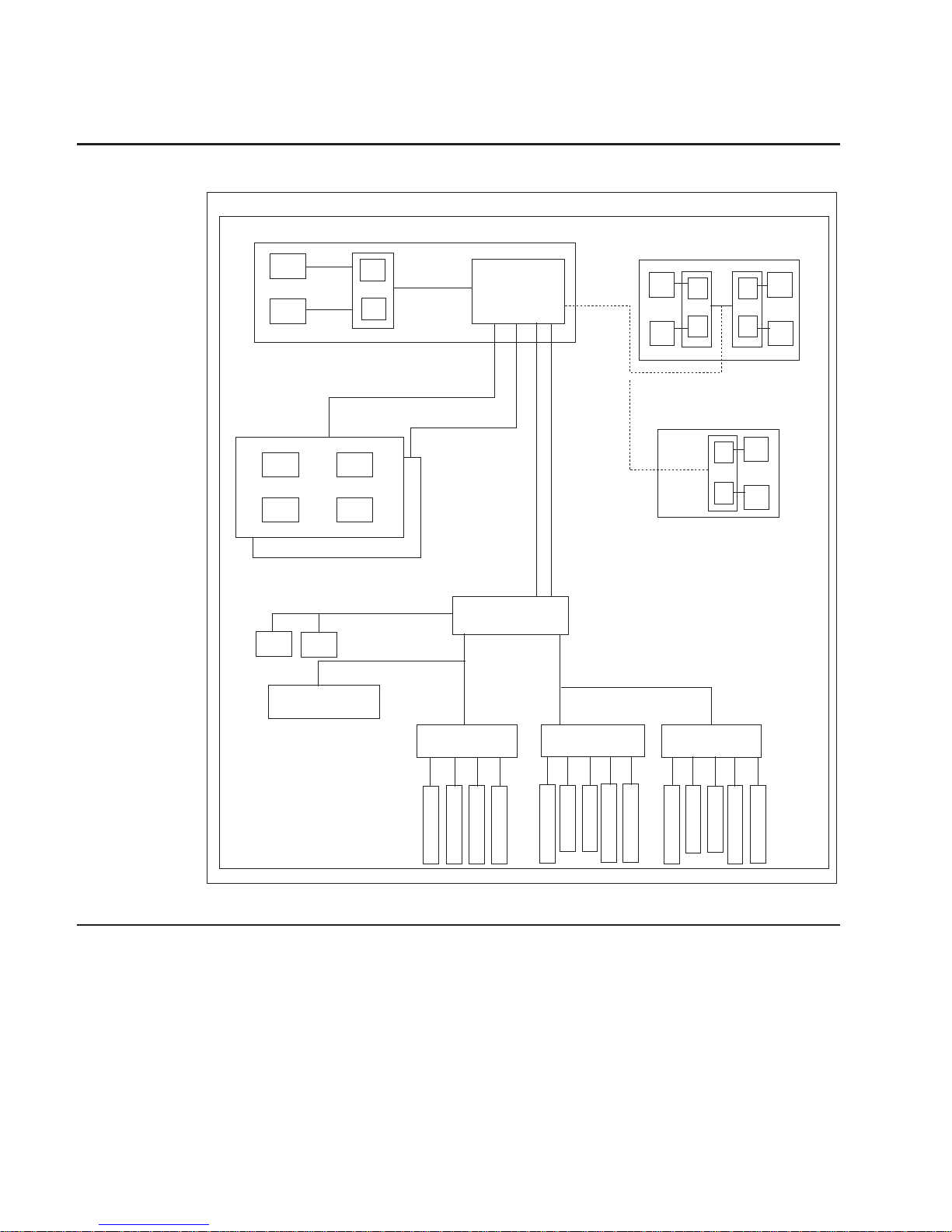
Data Flow with One-Way Processor
L2
Processor Card (1 way only)
6XX
Bus 0
P
Memory Card
(1 only is optional)
Memory Card
(1 only is optional)
SMI BUS 0, 1
SMI
SMI
SMI
SMI
SMI
SMI
SMI BUS 2, 3
64-bit
PCI Bus 2
64-bit
PCI Bus 2
RIO
(2)
PCI Host Bridge
Memory
Controller
Memory
Controller
64-bit
PCI Bus 1
64-bit
PCI Bus 1
32-bit PCI Bus 0
PCI to PCI
Bridge 3
PCI to PCI
Bridge 3
5V5V
PCI to PCI
Bridge 2
PCI to PCI
Bridge 2
5V5V
3.3V3.3
V
3.3V3.3
V
3.3V3.3
V
3.3V3.3
V
3.3V3.3
V
3.3V3.3
V
3.3V3.3
V
3.3V3.3
V
3.3V3.3
V
3.3V3.3
V
PCI to PCI
Bridge 1
PCI to PCI
Bridge 1
Converged Support
Processor
Converged Support
Processor
S
L
O
T
2
S
L
O
T
2
S
L
O
T
1
S
L
O
T
1
S
L
O
T
6
S
L
O
T
6
S
L
O
T
3
S
L
O
T
3
S
L
O
T
7
S
L
O
T
7
S
L
O
T
13
S
L
O
T
13
S
L
O
T
14
S
L
O
T
14
S
L
O
T
10
S
L
O
T
10
S
L
O
T
4
S
L
O
T
4
S
L
O
T
5
S
L
O
T
5
S
L
O
T
8
S
L
O
T
8
S
L
O
T
9
S
L
O
T
9
S
L
O
T
11
S
L
O
T
11
S
L
O
T
12
S
L
O
T
12
SCSI
10/100
E’net
10/100
E’net
256 MB - 16 GB
Chapter 1. Reference Information 3
Page 22
Data Flow with Two- to Six-Way Processor
L2
2-Way System
6XX
Bus 0
L2
P
P
L2
L2
P
6XX
Bus 1
Memory Cards
(1 or 2)
Memory Cards
(1 or 2)
256 MB - 32 GB
SMI BUS 0, 1
SMI
SMI
SMI
SMI
SMI BUS 2, 3
64-bit
PCI Bus 2
64-bit
PCI Bus 2
RIO
(2)
6-Way System
L2
L2
P
4-Way System
OR
L2
L2
P
P P
P
PCI Host Bridge
Memory
Controller
Memory
Controller
64-bit
PCI Bus 1
64-bit
PCI Bus 1
32-bit PCI Bus 0
10/100
E’net
10/100
E’net
PCI to PCI
Bridge 3
PCI to PCI
Bridge 3
3.3V3.3
V
3.3V3.3
V
5V
PCI to PCI
Bridge 2
PCI to PCI
Bridge 2
3.3V3.3
V
3.3V3.3
V
5V
5V
3.3V3.3
V
3.3V3.3
V
3.3V3.3
V
3.3V3.3
V
5V
3.3V3.3
V
3.3V3.3
V
PCI to PCI
Bridge 1
PCI to PCI
Bridge 1
Converged Support
Processor
Converged Support
Processor
S
L
O
T
2
S
L
O
T
2
S
L
O
T
1
S
L
O
T
1
S
L
O
T
7
S
L
O
T
7
S
L
O
T
6
S
L
O
T
6
S
L
O
T
5
S
L
O
T
5
S
L
O
T
3
S
L
O
T
3
S
L
O
T
8
S
L
O
T
8
S
L
O
T
11
S
L
O
T
11
S
L
O
T
10
S
L
O
T
10
S
L
O
T
4
S
L
O
T
4
S
L
O
T
9
S
L
O
T
9
S
L
O
T
12
S
L
O
T
12
S
L
O
T
13
S
L
O
T
13
S
L
O
T
14
S
L
O
T
14
SCSI
Powering the System On and Off
The system can be powered on after the following cables are connected:
v V/S COMM Cable
v All RIO cables
v All SPCN cables
v JTAG Cable
v All PCI cables to supported drawers
4 Service Guide
Page 23

After the required cables are installed, and the power cables are connected, the power
button on the primary I/O drawer operator panel can be pushed to initialize the system.
Progress indicators, also referred to as
checkpoints
, are visible on the primary I/O
drawer operator panel display and the power LED on the primary I/O drawer stops
blinking and stays on, indicating the system power is on.
The CEC drawer and secondary I/O drawers are powered on through the primary I/O
drawer system power control network (SPCN). When power is applied, the power LEDs
on the CEC drawer and primary I/O drawer go from blinking to on continuously, and the
power LED on the secondary I/O drawer comes on and stays on. This indicates that
power levels are satisfactory in the drawers.
If the system is operating under AIX, type the shutdown command to power off the
system. If you cannot use this method, you can power off the system by pressing the
primary I/O drawer operator-panel power button.
Attention: Using the operator-panel power pushbutton to power off the system can
cause unpredictable results in the data files, and the next IPL will take longer to
complete.
For complete details on how to power on and off the system, go to “Powering Off and
Powering On the System” on page 429 and “System Power-On Methods” on page 398.
Console Strategy
The firmware starts a console-selection sequence at system boot time if any of the
following is true:
v A console has not yet been selected.
v A previous console-selection sequence timed-out.
v A change in the system configuration affects the console (keyboard
installed/removed, mouse installed/removed, graphics adapter installed/removed or
moved to another PCI slot).
The console-selection sequence allows you to select (from the appropriate input device)
any one of the available console devices. If no console is selected within approximately
60 seconds, serial port 1 (S1) is selected as the console and the selection sequence
times-out.
Attention: If an ASCII terminal is attached to serial port 1 (S1), and there is any
interaction with this terminal, then:
v After OK displays in the operator panel
AND
v Before the power-on sequence is initiated
the firmware will use this terminal as the console, regardless of the previous console
selection.
Chapter 1. Reference Information 5
Page 24

After a console has been selected, the console-selection sequence is only started at
boot time if there is a change in the system configuration (as described above), or the
contents of the system’s nonvolatile memory (NVRAM) are lost.
Note: Moving an ASCII terminal from one serial port to another (from S1 to S2) cannot
be detected by the firmware, so it does not constitute a configuration change.
You can also initiate a system console-selection sequence from the SMS menus.
Power-On Self-Test
After power is turned on and before the operating system is loaded, the system does a
power-on self-test (POST). This test performs checks to ensure that the hardware is
functioning correctly before the operating system is loaded. During the POST, a POST
screen displays, and POST indicators appear on the firmware console (if one is
connected). The next section describes the POST indicators and functions that can be
accessed during the POST.
POST Indicators
POST indicators indicate tests that are being performed as the system is preparing to
load the operating system. The POST indicators are words that display on the system
console. Each time that the system starts a different step in the POST, a POST
indicator word appears on the console. Each word is an indicator of the tests that are
being performed.
The POST screen displays the following words:
Memory Memory test
Keyboard Initialize the keyboard and mouse. The time period for pressing a key
to access the System Management Services, or to initiate a service
mode boot is now open. See “POST Keys” for more information.
Network Self-test on network adapters
SCSI Adapters are being initialized
Speaker Sounds an audible tone at the end of POST
POST Keys
The POST keys, if pressed
after
the keyboard POST indicator displays and
before
the
last POST indicator speaker displays, cause the system to start services or to initiate
service mode boots used for configuring the system and diagnosing problems. The keys
are described below:
Note: The program function keys (F1-F12) on a keyboard attached to the I/O drawer
are not used and will be ignored. After the keyboard POST indicator displays,
you must use the numeric number keys to enter input.
6 Service Guide
Page 25

1 Key
The numeric 1 key, when pressed during POST, starts the System Management
Services (SMS) interface.
5 Key
The numeric 5 key, when pressed during POST, initiates a system boot in service mode
using the default service mode boot list.
This mode attempts to boot from the first device of each type found in the list. It does
not search for other bootable devices of that type if the first device is not bootable.
Instead, it continues to the next device type in the list. The firmware supports up to five
entries in the boot list.
The default boot sequence is:
1. Diskette
2. CD-ROM
3. Hard file
4. Tape drive (if installed)
5. Network
a. Token ring
b. Ethernet
6 Key
The numeric 6 key works like the numeric 5 key, except that firmware uses the
customized service mode bootlist that was set up using the AIX service aids.
8 Key
To enter the open firmware command line, press the numeric 8 key
after
the word
keyboard displays and before the last word speaker displays during startup. After you
press the 8 key, the remaining POST indicators display until initialization completes.
When initialization and POST are complete, the open firmware command line (an OK
prompt) displays.
The open firmware command line should only be used by service personnel to obtain
additional debug information.
To exit from the open firmware command prompt, type reset-all or power off the
system and reboot.
Chapter 1. Reference Information 7
Page 26
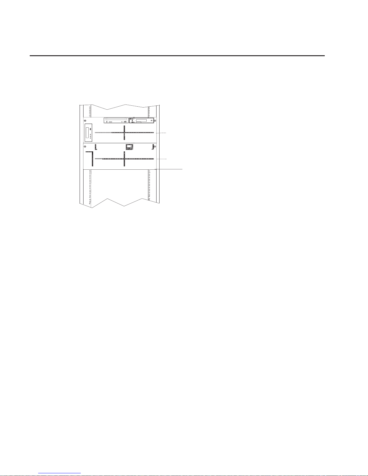
System Unit Locations
The system consists of a minimum of two drawers in one rack: the CEC drawer and the
primary I/O drawer. These two components are connected by cables that transmit data
and control signals. An additional I/O drawer can be added if further expansion of the
system is required. The following figure shows the units.
R
CEC Drawer
(5 EIA Units)
Primary
I/O Drawer
(5 EIA Units)
8 Service Guide
Page 27

CEC Drawer Front View
1
1 Power-On LED
Chapter 1. Reference Information
9
Page 28
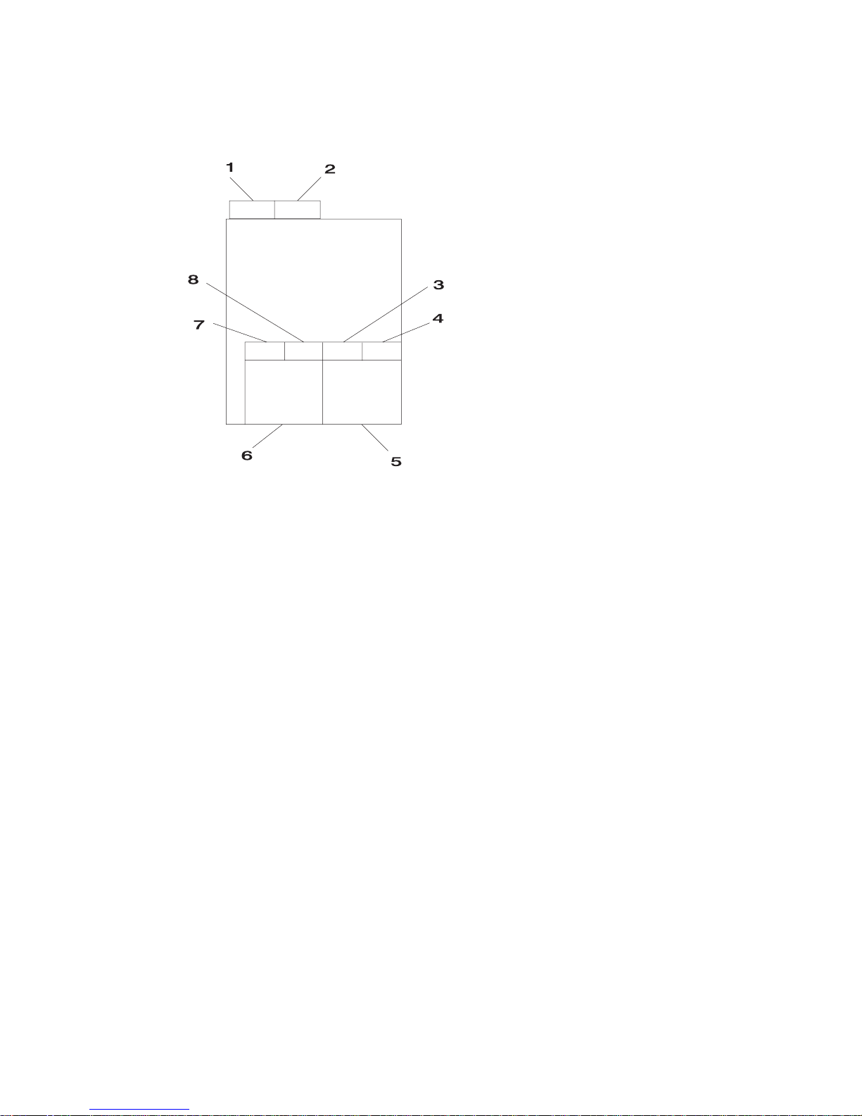
CEC Drawer Top View
1 Fan 8 U1.1-F8 2 Fan 7 U1.1-F7
3 Fan 2 U1.1-F2 4 Fan 1 U1.1-F1
5 Power Supply 1 with
Fan 5 U1.1-V1
6 Power Supply 2 with
Fan 6 U1.1-V2
or Cooling Unit Fan 9
U1.1-F9
7 Fan 4 U1.1-F4 8 Fan 3 U1.1-F3
10 Service Guide
Page 29

CEC Drawer Rear View
1
2
3
4
5
6
1 V/S COMM 2 RIO 0
3 RIO 1 4 JTAG
5 Fan 7 6 Fan 8
Chapter 1. Reference Information
11
Page 30
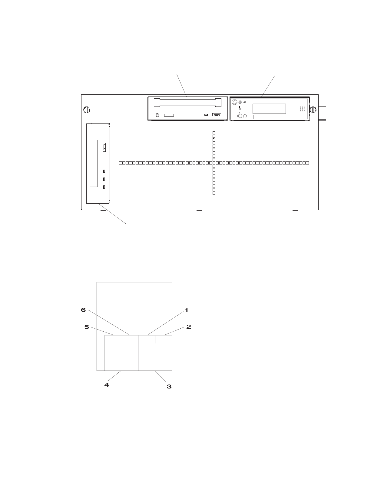
Primary I/O Drawer Front View
1
2
3
R
1 CD-ROM drive 2 Operator panel
3 Tape drive (optional)
Primary I/O Drawer Top View
1 Fan 2 U0.1-F2 2 Fan 1 U0.1-F1
3 Power Supply 1 with
Fan 5 U0.1-V1
4 Power Supply 2 with
Fan 6 U0.1-V2
or Cooling Unit Fan 9
U0.1-F9
12 Service Guide
Page 31

5 Fan 4 U0.1-F4 6 Fan 3 U0.1-F3
Chapter 1. Reference Information
13
Page 32

Primary I/O Drawer Rear View
1
9
10
18
17
19
11
12
13
14
15
16
2
3
4
5
6
7
8
1
2
3
4
5
6
14
1312
11
10
9
8
7
P1
1 Ethernet connector 2 SCSI connector
3 Debug 4 Mouse connector
5 Serial port 1 6 Serial port 2
7 J11 (SPCN 1
connector)
8 J14 (SPCN 3
connector, reserved)
9 V/S COMM 10 JTAG connector
11 Parallel port 12 Keyboard connector
13 Serial port 3 14 Serial port 4
15 J15 (SPCN 2
connector)
16 J16 (SPCN 4
connector)
17 Hot-Plug LED (one for
each adapter)
18 RIO 1 connector
19 RIO 0 connector
14 Service Guide
Page 33

Primary I/O Drawer Front View with Covers Removed
1
4
5
6
7
2
3
R
1 Bay A - Diskette drive 2 Bay B - CD-ROM drive
3 Bay C - Operator panel 4 Bay D - Tape drive
(optional)
5 Power supply 2 6 Power supply LEDs
7 Power supply 1
Chapter 1. Reference Information
15
Page 34

Secondary I/O Drawer Front View
1
2
3
1 Optional media bay 2 Operator panel
3 Optional media bay
Secondary I/O Drawer Top View
1 Fan 2 U0.2-F2 2 Fan 1 U0.2-F1
3 Power Supply 1 with
Fan 5 U0.2-V1
4 Power Supply 2 with
Fan 6 U0.2-V2
or Cooling Unit Fan 9
U0.2-F9
16 Service Guide
Page 35

5 Fan 4 U0.2-F4 6 Fan 3 U0.2-F3
Chapter 1. Reference Information
17
Page 36

Secondary I/O Drawer Rear View
1
2
3
4
5
7
6
1
2
3
4
5
6
14
1312
11
10
9
8
8
7
P1
1 RIO 1 connector 2 RIO 0 connector
3 SCSI connector 4 J11 (SPCN 1
connector)
5 J14 (SPCN 3
connector)
6 J16 (SPCN 2
connector)
7 J15 (SPCN 4
connector)
8 Hot-plug LED (one for
each adapter)
18 Service Guide
Page 37

PCI Board Locations
PCI
Slot I1
PCI
Slot I7
PCI
Slot I8
PCI
Slot I14
Battery
Socket
Chapter 1. Reference Information 19
Page 38

System Board Locations
1
2
3
4
5
6
7
9
8
1 Power distribution board connector 2 Processor card connecter
3 Memory riser card 1 connector 4 Memory riser card 2 connector
5 JTAG connector 6 RIO 1 connector
7 RIO 0 connector 8 V/S COMM connector
9 SPCN connector
20 Service Guide
Page 39

Memory Riser Card and Memory DIMM Locations
(15) A
(16) A
(14) B
(12) C
(10) D
(8) D
(6) C
(4) B
(2) A
(13) B
(11) C
(9) D
(7) D
(5) C
(3) B
(1) A
Location Code Memory DIMMs
U1.1-P1-M1.n Memory DIMMs on riser card 1 (n denotes
DIMM number)
U1.1-P1-M2.n Memory DIMMs on riser card 2 (n denotes
DIMM number)
U1.1-P1-M1.1 x2 Memory pair A (DIMMs 1 and 15)
U1.1-P1-M1.1 x4 Memory quad A (DIMMs 1, 2, 15, 16)
U1.1-P1-M1.3 x4 Memory quad B (DIMMs 3, 4, 13, 14)
U1.1-P1-M1.5 x4 Memory quad C (DIMMs 5, 6, 11, 12)
U1.1-P1-M1.7 x4 Memory quad D (DIMMs 7, 8, 9, 10)
U1.1-P1-M2.1 x2 Memory pair A (DIMMs 1 and 15)
U1.1-P1-M2.1 x4 Memory quad A (DIMMs 1, 2, 15, 16)
U1.1-P1-M2.3 x4 Memory quad B (DIMMs 3, 4, 13, 14)
U1.1-P1-M2.5 x4 Memory quad C (DIMMs 5, 6, 11, 12)
U1.1-P1-M2.7 x4 Memory quad D (DIMMs 7, 8, 9, 10)
U1.1-P1-M1.1 x16 All memory DIMMs on riser card 1
U1.1-P1-M2.1 x16 All memory DIMMs on riser card 2
U1.1-P1-M1 x2 All memory DIMMs on riser cards 1 and 2
Chapter 1. Reference Information
21
Page 40

One-Way Processor Card Memory DIMM Locations
(8) A
(7) B
(6) C
(5) D
(3) C
(4) D
(2) B
(1) A
Location Code Memory DIMMs
U1.1-P1-C1-Mn Memory DIMMs on processor card (n denotes
DIMM number)
U1.1-P1-C1-M1 x2 Memory pair A (DIMMs 1 and 8)
U1.1-P1-C1-M2 x2 Memory pair B (DIMMs 2 and 7)
U1.1-P1-C1-M3 x2 Memory pair C (DIMMs 3 and 6)
U1.1-P1-C1-M4 x2 Memory pair D (DIMMs 4 and 5)
U1.1-P1-C1-M1 x8 All memory DIMMs on processor card
22 Service Guide
Page 41

Primary I/O Drawer Operator Panel
R
1
2
5
3
4
6
1 Power on/off button 2 Power on/off LED
3 Operator panel display 4 Reset button
5 Service processor
reset button opening
6 Disturbance or system
attention LED
Note: The service processor reset button should only be activated as part of a service
action and must therefore be activated very carefully. An insulated paper clip is
recommended. Unbend the clip so that it has a straight section about two inches
long. Insert the clip straight into the hole, keeping the clip perpendicular to the
plastic bezel. When you engage the reset switch, you should feel the detent of
the switch. After you press the switch, the service processor resets and then
shuts down the system.
Chapter 1. Reference Information 23
Page 42

Secondary I/O Drawer Operator Panel
1
2
1 Power present LED 2 Disturbance or system
attention LED
24 Service Guide
Page 43

SCSI IDs and Bay Locations
The following figure shows the SCSI IDs for media devices. The SCSI IDs for media
devices installed at the factory are set using jumpers on the drives when they are
installed. The SCSI IDs are set as shown in the following figure.
1
2
R
Note: The SCSI IDs shown for media devices indicate how the IDs are set when the
system is shipped from the factory.
1 CD-ROM drive (SCSI
ID= 1)
2 Tape drive (SCSI ID=
0)
Chapter 1. Reference Information
25
Page 44

System Memory
Two slots are available for system memory riser cards. The system memory riser cards
are located for easy access in the CEC drawer. (These slots are shown in “System
Board Locations” on page 20.) Each memory riser card has 16 DIMM slots.
Four sizes of DIMMs are available: 128 MB, 256 MB, 512 MB and 1 GB. In addition,
certain 32 MB DIMMS from earlier RS/6000 systems can also be used.
One-Way Processor Memory Placement Rules
The rules for one-way processor memory are as follows:
v Minimum memory is 1 pair of DIMMs in slots 1 and 8 (see “One-Way Processor Card
Memory DIMM Locations” on page 22).
v Maximum memory is 4 DIMM pairs in slots 1 through 8 (see “One-Way Processor
Card Memory DIMM Locations” on page 22).
v Each memory riser slot must have a memory filler card installed.
v When you are installing a memory riser card:
– Memory DIMMs must be moved from the one-way processor card to the memory
riser card.
– The memory riser card must then have a minimum of four DIMMS (1 quad).
Riser Card Memory Placement Rules
The rules for riser card memory are as follows:
v Memory quads must contain DIMMs of equal memory size.
v Quad memory size may be mixed on a riser card.
v The minimum memory is four DIMMs. This memory must occupy quad A, which is
slots 1, 2, 15, and 16 (see “Memory Riser Card and Memory DIMM Locations” on
page 21).
v Populate the riser card starting with quad A and continuing with quads B, C, and D
(see “Memory Riser Card and Memory DIMM Locations” on page 21).
26 Service Guide
Page 45

I/O Drawer Features
I/O drawers may have two redundant power supplies. One of these power supplies is
capable of providing the necessary voltages and currents independently of the other.
The left and right power supply output voltages are connected and monitored by the
power distribution board contained in the 5 EIA-unit I/O drawer. Both power supplies
provide +12 V dc to the fans in the drawer to ensure sufficient cooling if one of the
supplies fails. However, the short circuit prevention is on the I/O board to protect
against shorts in one output, thus causing the +12 V dc to fail completely.
The left and right power supplies are hot-pluggable and may be changed one-at-a-time
while the system is operational. Each power supply provides 5 V dc, 3.3 V dc, 12 V dc,
and5Vdcstandby power.
The5Vdcstandby power is provided by both power supplies; this can be done
because the power supplies contain overload protection against one supply shorting the
other. Standby power (5 V dc) is provided to the part of the primary I/O drawer planar
on which the SPCN and service processor logic reside.
I/O Drawer Addressing
I/O drawer addressing refers to the drawer number that is displayed in the operator
panel on secondary I/O drawers. This address is the drawer’s location in the RIO
(remote I/O) loop. The drawer number is displayed in the form U0.n, where n is the
drawer number. The primary I/O drawer number is 1 by default, but it is not displayed
on the operator panel. The first time that the system is booted after a service action or
configuration change that involves an I/O drawer or its backplane, the system may
detect a duplicate or incorrect I/O drawer number. This situation can result in duplicate
or incorrect drawer numbers being displayed when the system is booting up. The final
drawer number will be assigned and displayed, when the bootup is complete. The
drawer numbers are not reassigned unless a service action or configuration change
occurs.
When ac power has been disconnected from the system or from a drawer, then
reconnected, the I/O drawer address temporarily displays in the format *0n, where n is
the drawer number. After the system is powered on, and the boot sequence has been
initiated, the drawer numbers are restored to the U0.n format.
Chapter 1. Reference Information 27
Page 46

I/O Drawer and Power Supply LED Status
The following table summarizes the possible conditions of I/O drawer and power supply
LEDs:
Status of LED Operator Panel LED Right Power Supply
LED
Left Power Supply
LED
Off No power connected No power connected
or system power
connected, not turned
on, power supply
detects NO faults
No power connected
or system power
connected, not turned
on, power supply
detects NO faults
On, blinking green System power
connected, not turned
on
System power
connected, not turned
on, power supply
detected fault
System power
connected, not turned
on, power supply
detected fault
On, steady green System power
connected and turned
on
System power
connected and turned
on
System power
connected and turned
on
28 Service Guide
Page 47

Message Hierarchy for Secondary I/O Drawer Operator Panel
The messages that are displayed in the operator panel on secondary I/O drawers are
arranged hierarchically, from highest priority to lowest priority. The message hierarchy is
as follows:
1. 8-character error code
This indicates a critical error; the drawer power will be shut down. Standby power is
still on, so the error message is still displayed in the operator panel. The I/O drawer
Attention LED will be on. The error code displays on the top line of the display
panel, left-justified. A FRU part number may also be displayed, right-justified, in the
second line of the display.
2. 8-character informational message
This is a noncritical message, so the drawer power will not be shut down. The
message should be investigated to see if service actions are indicated. A FRU part
number may also be displayed, right-justified, in the second line of the display.
When 8-character codes are displayed, they are in the form 10n1xxxx, where n is
the drawer number.
3. 8-character checkpoint
There is one 8-character checkpoint that will be displayed, 10n100AA, where n is the
drawer number. This checkpoint indicates that the system power control network
firmware is being updated, and the checkpoint will be displayed for approximately
15 seconds. This is the only checkpoint that displays on a secondary I/O drawer
operator panel.
4. Drawer number
This will be in the form U0.n, where n is the drawer number. This message will
normally be displayed unless a higher-level message is required.
When ac power has been disconnected from the system, then reconnected, the I/O
drawer addresses on the secondary drawers will temporarily display in the format
*0n, where n is the drawer number. After the system is powered on, and the boot
sequence has been initiated, the drawer numbers are restored to the U0.n format.
Chapter 1. Reference Information 29
Page 48

Primary I/O Drawer Operator Panel Behavior During Power-On
After Connecting AC Power
Drawer State Power LED Drawer Operator Panel
Display
Standby Blinking slowly 8xxx checkpoints followed by
OK
System power On Blinking fast 9xxx checkpoints ending with
E1FF
Receive firmware command On solid Exxx checkpoints ending with
E105
Thereafter On solid 0xxx checkpoints ending with a
blank display
After Power is Removed Because of a Breakdown
Drawer State Power LED Drawer Operator Panel
Display
Standby Blinking slowly OK is displayed
System power On Blinking fast 9xxx checkpoints ending with
E1FF
Receive firmware command On solid Exxx checkpoints ending with
E105
Thereafter On solid 0xxx checkpoints ending with a
blank display
Critical error codes are posted on the top line (left-justified) of the drawer display with
the attention light on solid. Any location codes are posted on the bottom line
(left-justified).
Noncritical error codes are not posted. The drawer display remains blank with the
attention light on solid.
30 Service Guide
Page 49

Secondary I/O Drawer Operator Panel Behavior During Power-On
After Connecting AC Power
Drawer State Power LED Drawer Operator Panel
Display
Standby Off Display shows a temporary
drawer ID
Receive firmware command to
power on
On solid Message based on “Message
Hierarchy for Secondary I/O
Drawer Operator Panel” on
page 29.
After Power is Removed Because of a Shutdown
Drawer State Power LED Drawer Operator Panel
Display
Standby Off Message based on “Message
Hierarchy for Secondary I/O
Drawer Operator Panel” on
page 29
Receive firmware command to
power on
On solid Message based on “Message
Hierarchy for Secondary I/O
Drawer Operator Panel” on
page 29
Chapter 1. Reference Information
31
Page 50

Logical and Physical Locations
The system uses physical location codes in conjunction with AIX location codes to
provide mapping of the failing field replaceable units (FRUs). The location codes are
produced by the system unit’s firmware and the AIX operating system.
Physical Location Codes
Physical location codes provide a mapping of logical functions in a platform (or
expansion sites for logical functions, such as connectors or ports) to their specific
locations within the physical structure of the platform.
Location Code Format
The format for the location code is a string of alphanumeric characters separated by a
dash (-), slash (/), pound sign (#) or period (.) character. The base location is all of the
information preceding the slash (/) or pound sign (#). The base location identifies a
device that is connected to or plugged into the parent. Extended location information
follows the slash (/). Extended location information identifies a device that is part of the
parent, a connector, or a cable. Cable information follows the pound sign (#). Cable
information identifies a cable that is connector to parent. The following are examples:
v P1-C1 identifies a processor card C1 plugged into planar P1.
v P1-M1 identifies a memory card M1 plugged into planar P1.
v P1-K1 identifies a keyboard attached to K1 on planar P1.
v P1/S1 identifies serial port 1 controller on planar P1, the connector for serial port 1,
or the cable attached to serial port 1.
v P1-I2/E3 identifies an Ethernet controller 3 on the card in slot 2 (I2) on planar P1, the
connector for Ethernet controller 3, or the cable attached to Ethernet controller 3.
v P1-I2#E3 identifies the cable attached to Ethernet controller 3 on the card in slot 2
(I2) on planar P1.
The period (.) identifies sublocations (DIMMs on a memory card, SCSI addresses,
cables). The following are examples:
v P1-M1.4 identifies DIMM 4 on memory card 1 plugged into planar P1.
v P1-C1.1 identifies processor 1 plugged into processor card 1 which is plugged into
planar P1.
v U0.1-P1/Z1–A3 identifies a SCSI device with SCSI ID 3 attached to SCSI bus 1 on
planar 1 in the primary I/O drawer.
v P2-Z1-A3.1 identifies a SCSI device with SCSI address of LUN 1 at SCSI ID 3
attached to SCSI bus 1 from planar 2.
v P1-I2#E3.2 identifies the second in a series of cables attached to Ethernet controller
3 on the card in slot 2 (I2) on planar P1.
Depending on the AIX and firmware levels, AIX diagnostics may include the extended
location information when identifying a planar or card. The extended location
information or cable information is always included when identifying a cable or
connector. Location codes with extended location information that are displayed without
a description identifying the devices always identify the cable attached to the port.
32 Service Guide
Page 51

Multiple FRU Callout Instructions
If an eight-digit error code appears in the operator panel display or in Chapter 5, “Error
Code to FRU Index” on page 163, a location code for a failing part may also be
specified. If the location code includes a blank space followed by a lowercase x
followed by a number, this is an error code with multiple FRU callouts. This error can
typically happen with memory DIMMs, memory riser cards, or processors and may
involve mixed types of parts. In this case, check the system’s configuration FRU part
numbers to determine the appropriate set of FRUs.
For example, if the location code U1.1-P1-M1.1 x2 was displayed, this indicates
memory pair A (two DIMMs) on the first memory riser card was suspected.
You can determine the FRU part numbers of the electronic assemblies in the system in
two ways:
v Using the service processor menus
From the general user menu, select Read VPD Image from Last System Boot,
then enter 90 to display detailed vital product data (VPD).
v Using the lscfg -vp | pg command on the AIX command line
Type the following command: lscfg -vp | pg to display the detailed VPD of all
assemblies. Notice that the FRU part number information for processors and memory
DIMMs may be at the bottom of the command output.
Chapter 1. Reference Information 33
Page 52

AIX Location Codes
The basic formats of the AIX location codes are as follows:
v For non-SCSI devices/drives:
– AB-CD-EF-GH
v For SCSI devices/drives:
– AB-CD-EF-G,H
For planars, cards, and non-SCSI devices, the location code is defined as follows:
AB-CD-EF-GH
||||
| | | Device/FRU/Port ID
| | Connector ID
| devfunc Number, Adapter Number or Physical Location
Bus Type or PCI Parent Bus
v The AB value identifies a bus type or PCI parent bus as assigned by the firmware.
v The CD value identifies adapter number, adapter’s devfunc number, or physical
location. The
devfunc
number is defined as the PCI device number times 8, plus the
function number.
v The EF value identifies a connector.
v The GH value identifies a port, address, device, or FRU.
Adapters and cards are identified only with AB-CD.
The possible values for CD depend on the adapter/card. For pluggable PCI
adapters/cards, CD is the device’s devfunc number (PCI device number times 8, plus
the function number). The C and D are characters in the range of 0-9, and A-F (hex
numbers). The location codes therefore uniquely identify multiple adapters on individual
PCI cards.
EF is the connector ID, used to identify the adapter’s connector to which a resource is
attached.
GH is used to identify a port, device, or FRU. For example:
v For async devices, GH defines the port on the fanout box. The values are 00 to 15.
v For a diskette drive, H identifies either diskette drive 1 or 2. G is always 0.
v For all other devices, GH is equal to 00.
For integrated adapter, EF-GH is the same as the definition for a pluggable adapter. For
example, the location code for a diskette drive is 01-D1-00-00. A second diskette drive
is 01-D1-00-01.
34 Service Guide
Page 53

For SCSI devices, the location code is defined as follows:
AB-CD-EF-G,H
| | |||
| | | | Logical Unit address of the SCSI Device
| | | Control Unit Address of the SCSI Device
| | Connector ID
| devfunc Number, Adapter Number or Physical Location
Bus Type or PCI Parent Bus
Where:
v AB-CD-EF are the same as non-SCSI devices.
v G defines the control unit address of the device. Values of 0 to 15 are valid.
v H defines the logical unit address of the device. Values of 0 to 255 are valid.
A bus location code is also generated as ’00-XXXXXXXX’, where XXXXXXXX is
equivalent to the node’s unit address.
Examples of physical location codes and AIX location codes are:
1. PCI adapter in primary I/O drawer, slot 1
v Location Code U0.1-P1-I1
v AIX Location Code 11-08
2. PCI adapter in secondary I/O drawer, slot 1
v Location Code U0.2-P1-I1
v AIX Location Code 51-08
Chapter 1. Reference Information 35
Page 54

AIX and Physical Location Code Reference Tables
The following tables contain location codes that are used to identify functional units in
the system. Each of the following tables shows the locations for a physical part of the
system.
FRU Name Location Code AIX
Location
Code
Physical
Connection
Logical
Connection
CEC Drawer
CEC Drawer U1.1 00-00
CEC Backplane U1.1-P1 00-00
Processor Card U1.1-P1-C1 00-00 to
00-0A
Connector M03
Processor Card
Cache
U1.1-P1-C1 00-00
I/O Hub and
Interrupt Controller
U1.1-P1-C1 00-00
Regulator U1.1-P1-C1 00-00
Memory Controller U1.1-P1-C1 00-00
Memory DIMMs on
Processor Card
U1.1-P1-C1-M1 to
U1.1-P1-C1-M8
00-00 Refer to
“One-Way
Processor Card
Memory DIMM
Locations” on
page 22.
Memory Pair A on
Processor Card
U1.1-P1-C1-M1 x2 00-00 Refer to
“One-Way
Processor Card
Memory DIMM
Locations” on
page 22.
Memory Pair B on
Processor Card
U1.1-P1-C1-M2 x2 00-00 Refer to
“One-Way
Processor Card
Memory DIMM
Locations” on
page 22.
Memory Pair C on
Processor Card
U1.1-P1-C1-M3 x2 00-00 Refer to
“One-Way
Processor Card
Memory DIMM
Locations” on
page 22.
Memory Pair D on
Processor Card
U1.1-P1-C1-M4 x2 00-00 Refer to
“One-Way
Processor Card
Memory DIMM
Locations” on
page 22.
36 Service Guide
Page 55

FRU Name Location Code AIX
Location
Code
Physical
Connection
Logical
Connection
All memory DIMMs
on Processor Card
U1.1-P1-C1-M1 x8 00-00 Refer to
“One-Way
Processor Card
Memory DIMM
Locations” on
page 22.
Riser Card 1
Memory DIMMs 1 16
U1.1-P1-M1.1 to
U1.1-P1-M1.16
00-00 Refer to “Memory
Riser Card and
Memory DIMM
Locations” on
page 21.
Memory pair A on
riser card 1
U1.1-P1-M1.1 x2 00-00 Refer to “Memory
Riser Card and
Memory DIMM
Locations” on
page 21.
Memory quad A on
riser card 1
U1.1-P1-M1.1 x4 00-00 Refer to “Memory
Riser Card and
Memory DIMM
Locations” on
page 21.
Memory quad B on
riser card 1
U1.1-P1-M1.3 x4 00-00 Refer to “Memory
Riser Card and
Memory DIMM
Locations” on
page 21.
Memory quad C on
riser card 1
U1.1-P1-M1.5 x4 00-00 Refer to “Memory
Riser Card and
Memory DIMM
Locations” on
page 21.
Memory quad D on
riser card 1
U1.1-P1-M1.7 x4 00-00 Refer to “Memory
Riser Card and
Memory DIMM
Locations” on
page 21.
All memory on riser
card 1
U1.1-P1-M1.1 x16 00-00 Refer to “Memory
Riser Card and
Memory DIMM
Locations” on
page 21.
Riser Card 2
Memory DIMMs 1 16
U1.1-P1-M2.1 to
U1.1-P1-M2.16
00-00 Refer to “Memory
Riser Card and
Memory DIMM
Locations” on
page 21..
Chapter 1. Reference Information
37
Page 56

FRU Name Location Code AIX
Location
Code
Physical
Connection
Logical
Connection
Memory quad A on
riser card 2
U1.1-P1-M2.1 x4 00-00 Refer to “Memory
Riser Card and
Memory DIMM
Locations” on
page 21.
Memory quad B on
riser card 2
U1.1-P1-M2.3 x4 00-00 Refer to “Memory
Riser Card and
Memory DIMM
Locations” on
page 21.
Memory quad C on
riser card 2
U1.1-P1-M2.5 x4 00-00 Refer to “Memory
Riser Card and
Memory DIMM
Locations” on
page 21.
Memory quad D on
riser card 2
U1.1-P1-M2.7 x4 00-00 Refer to “Memory
Riser Card and
Memory DIMM
Locations” on
page 21.
All memory on riser
card 2
U1.1-P1-M2.1 x16 00-00 Refer to “Memory
Riser Card and
Memory DIMM
Locations” on
page 21.
All memory (both
riser cards)
U1.1-P1-M1 x2 00-00 Connectors M01
and M02
RIO Port 0
Connector
U1.1-P1-C1/Q3
RIO Port 1
Connector
U1.1-P1-C1/Q2
RIO Port 0
Cable/Connector
U1.1-P1/Q3
RIO Port 1
Cable/Connector
U1.1-P1/Q2
V/S COMM
Connector
U1.1-P1/Q1
JTAG Connector U1.1-P1/Q4
Thermal Sensor U1.1-P1
Power Distribution
Card
U1.1-X1
Power Distribution
Card Connector 1
U1.1-X1/V1
38 Service Guide
Page 57

FRU Name Location Code AIX
Location
Code
Physical
Connection
Logical
Connection
Power Distribution
Card Connector 2
U1.1-X1/V2
Fan Controller Card U1.1-X2 PDB connector J3
LED Card U1.1-L1 PDB connector J6
Power Supply 1
(w/Fan 5)
U1.1-V1 PDB connector J2
Power Supply 2
(w/Fan 6)
U1.1-V2 PDB connector J1
Fan 1 U1.1-F1 Fan connector P3
on power supply
1
Fan 2 U1.1-F2 Fan connector P3
on power supply
1
Fan 3 U1.1-F3 Fan connector P3
on power supply
2
Fan 4 U1.1-F4 Fan connector P3
on power supply
2
Fan 7 U1.1-F7 PDB connector J7
Fan 8 U1.1-F8 PDB connector J7
Fan 9 U1.1-F9 In cooling unit
Primary I/O Drawer Locations
Primary I/O Drawer U0.1
Primary I/O
Backplane
U0.1-P1
Service Processor U0.1-P1
NVRAM U0.1-P1 Not used by
AIX
Service Processor
ISA Bridge
U0.1-P1 Not used by
AIX
Real Time Clock
(RTC)
U0.1-P1 Not used by
AIX
Timer U0.1-P1 Not used by
AIX
Interrupt Controller U0.1-P1 Not used by
AIX
DMA Controller U0.1-P1 Not used by
AIX
SPCN Controller U0.1-P1 I/O board
connector J2
Chapter 1. Reference Information
39
Page 58

FRU Name Location Code AIX
Location
Code
Physical
Connection
Logical
Connection
Battery U0.1-P1-V3
Diskette Controller U0.1-P1/D1 01-D1
Diskette Drive
Connector
U0.1-P1-D1 01-D1-00-00 I/O board
connector J28
Keyboard Controller U0.1-P1/K1 01-K1-00
Keyboard Connector U0.1-P1-K1 01-K1-00-00
Mouse Controller U0.1-P1-K11 O1-K1-01
Mouse U0.1-P1-O1 01-K1-01-00
V/S COMM
Connector
U0.1-P1/Q1
JTAG Connector U0.1-P1/Q4 Not used by
AIX
I/O board
connector J9
Parallel Port U0.1-P1/R1 01-R1
Serial Port 1 U0.1-P1/S1 01-S1
Serial Port 2 U0.1-P1/S2 01-S2
Serial Port 3 U0.1-P1/S3 01-S3
Serial Port 4 U0.1-P1/S4 01-S4
RIO Bus Adapter U0.1-P1.1
RIO Port 0
Connector
U0.1-P1.1/Q1
RIO Port 1
Connector
U0.1-P1.1/Q2
PCI Bus Controller 1 U0.1-P1 00-fff7f09000
ISA Bus U0.1-P1 10-80
PCI to PCI Bridge 1 U0.1-P1 10-58 10-5A
10-5C 10-5E
PCI Slot 1 U0.1-P1/I1 10-58
PCI Slot 1 Content U0.1-P1-I1 11-08 thru
11-0F or
12-xx or
13-xx
PCI Slot 2 U0.1-P1/I2 10-5A
PCI Slot 2 Content U0.1-P1-I2 14-08 thru
14-0F or
15-xx or
16-xx
PCI Slot 3 U0.1-P1/I3 10-5C
40 Service Guide
Page 59

FRU Name Location Code AIX
Location
Code
Physical
Connection
Logical
Connection
PCI Slot 3 Content U0.1-P1-I3 17-08 thru
17-0F or
18-xx or
19-xx
PCI Slot 4 U0.1-P1/I4 10-5E
PCI Slot 4 Content U0.1-P1-I4 1A-08 thru
1A-0F or
1B-xx or
1C-xx
PCI Bus Controller 2 U0.1-P1 00-fff7f0a000
PCI to PCI Bridge 2 U0.1-P1 20-58 20-5A
20-5B 20-5C
20-5E
PCI Slot 5 U0.1-P1/I5 20-58
PCI Slot 5 Content U0.1-P1-I5 21-08 thru
21-0F or
22-xx or
23-xx
PCI Slot 6 (5V) U0.1-P1/I6 20-5A
PCI Slot 6 Content U0.1-P1-I6 24-08 thru
24-0F or
25-xx or
26-xx
PCI Slot 7 (5V) U0.1-P1/I7 20-5B
PCI Slot 7 Content U0.1-P1-I7 27-08 thru
27-0F or
28-xx or
29-xx
PCI Slot 8 U0.1-P1/I8 20-5C
PCI Slot 8 Content U0.1-P1-I8 2A-08 thru
2A-0F or
2B-xx or
2C-xx
PCI Slot 9 U0.1-P1/I9 20-5E
PCI Slot 9 Content U0.1-P1-I9 2D-08 thru
2D-0F or
2E-xx or
2F-xx
PCI to PCI Bridge 3 U0.1-P1 20-60 20-62
20-63 20-64
20-66
PCI Slot 10 U0.1-P1/10 20-60
Chapter 1. Reference Information
41
Page 60

FRU Name Location Code AIX
Location
Code
Physical
Connection
Logical
Connection
PCI Slot 10 Content U0.1-P1-I10 31-08 thru
31-0F or
32-xx or
33-xx
PCI Slot 11 (5V) U0.1-P1/I11 20-62
PCI Slot 11 Content U0.1-P1-I11 34-08 thru
34-0F or
35-xx or
36-xx
PCI Slot 12 (5V) U0.1-P1/I12 20-63
PCI Slot 12 Content U0.1-P1-I12 37-08 thru
37-0F or
38-xx or
39-xx
PCI Slot 13 U0.1-P1/I13 20-64
PCI Slot 13 Content U0.1-P1-I13 3A-08 thru
3A-0F or
3B-xx or
3C-xx
PCI Slot 14 U0.1-P1/I14 20-66
PCI Slot 14 Content U0.1-P1-I14 3D-08 thru
3D-0F or
3E-xx or
3F-xx
PCI Bus Controller 0 U0.1-P1 00-fff7f08000
Integrated Ethernet U0.1-P1/E1 40-58
Internal SCSI
Controller
U0.1-P1/Z1 40-60
CD-ROM drive U0.1-P1/Z1-A1 40-60-00-1
Tape drive U0.1-P1/Z1-A0 40-60-00-0
Internal DASD 1 U0.1-P1/Z1-A4 40-60-00-4
Internal DASD 2 U0.1-P1/Z1-A8 40-60-00-8
External SCSI
Controller
U0.1-P1/Z2 40-61
Thermal Sensor
(Right)
U0.1-P1
Thermal Sensor
(Left)
U0.1-P1
Power Distribution
Card
U0.1-X1
Power Distribution
Card Connector 1
U0.1-X1/V1
42 Service Guide
Page 61

FRU Name Location Code AIX
Location
Code
Physical
Connection
Logical
Connection
Power Distribution
Card Connector 2
U0.1-X1/V2
Fan Controller Card U0.1-X2 PDB connector J3
Operator Panel U0.1-L1 N/A I/O board
connector J3
System VPD Module U0.1-L1-N1
Thermal Sensor
(Ambient)
U0.1-L1
Power Supply 1
(w/Fan 5)
U0.1-V1 PDB connector J2
Power Supply 2
(w/Fan 6)
U0.1-V2 PDB connector J1
Fan 1 U0.1-F1 Fan connector P3
on power supply
1
Fan 2 U0.1-F2 Fan connector P3
on power supply
1
Fan 3 U0.1-F3 Fan connector P3
on power supply
2
Fan 4 U0.1-F4 Fan connector P3
on power supply
2
Fan 9 U0.1-F9 In cooling unit
Service Processor
Firmware
U0.1-P1/Y2
System Firmware U0.1-P1/Y1
SPCN Firmware U0.1-P1/Y3
SPCN VPD U0.1-P1/Y4
Secondary I/O Drawer Locations
Secondary I/O
Drawer
U0.2
Secondary I/O
Backplane
U0.2-P1
SPCN Controller U0.2-P1 I/O board
connector J2
Ext. SCSI Connector U0.2-P1/Z1
RIO Bus Adapter U0.2-P1.1
RIO Port 0
Connector
U0.2-P1.1/Q1
Chapter 1. Reference Information
43
Page 62

FRU Name Location Code AIX
Location
Code
Physical
Connection
Logical
Connection
RIO Port 1
Connector
U0.2-P1.1/Q2
PCI Bus Controller 1 U0.2-P1 00-fff7e09000
PCI to PCI Bridge 1 U0.2-P1 50-58 50-5A
50-5C 50-5E
PCI Slot 1 U0.2-P1/I1 50-58
PCI Slot 1 Content U0.2-P1-I1 51-08 thru
51-0F or
52-xx or
53-xx
PCI Slot 2 U0.2-P1/I2 50-5A
PCI Slot 2 Content U0.2-P1-I2 54-08 thru
54-0F or
55-xx or
55-xx
PCI Slot 3 U0.2-P1/I3 50-5C
PCI Slot 3 Content U0.2-P1-I3 57-08 thru
57-0F or
58-xx or
59-xx
PCI Slot 4 U0.2-P1/I4 50-5E
PCI Slot 4 Content U0.2-P1-I4 5A-08 thru
5A-0F or
5B-xx or
5C-xx
PCI Bus Controller 2 U0.2-P1 000fff7e0a000
PCI to PCI Bridge 2 U0.2-P1 60-58 60-5A
60-5B 60-5C
60-5E
PCI Slot 5 U0.2-P1/I5 60-58
PCI Slot 5 Content U0.2-P1-I5 61-08 thru
61-0F or
62-xx or
63-xx
PCI Slot 6 (5V) U0.2-P1/I6 60-5A
PCI Slot 6 Content U0.2-P1-I6 64-08 thru
64-0F or
65-xx or
66-xx
PCI Slot 7 (5V) U0.2-P1/I7 60-5B
44 Service Guide
Page 63

FRU Name Location Code AIX
Location
Code
Physical
Connection
Logical
Connection
PCI Slot 7 Content U0.2-P1-I7 67-08 thru
67-0F or
68-xx or
69-xx
PCI Slot 8 U0.2-P1/I8 60-5C
PCI Slot 8 Content U0.2-P1-I8 6A-08 thru
6A-0F or
6B-xx or
6C-xx
PCI Slot 9 U0.2-P1/I9 60-5E
PCI Slot 9 Content U0.2-P1-I9 6D-08 thru
6D-0F or
6E-xx or
6F-xx
PCI to PCI Bridge 3 U0.2-P1 60-60 60-62
60-63 60-64
60-66
PCI Slot 10 U0.2-P1/I10 60-60
PCI Slot 10 Content U0.2-P1-I10 71-08 thru
71-0F or
72-xx or
73-xx
PCI Slot 11 (5V) U0.2-P1/I11 60-62
PCI Slot 11 Content U0.2-P1-I11 74-08 thru
74-0F or
75-xx or
76-xx
PCI Slot 12 (5V) U0.2-P1-I12 60-63
PCI Slot 12 Content U0.2-P1-I12 77-08 thru
77-0F or
78-xx or
79-xx
PCI Slot 13 U0.2-P1-/13 60-64
PCI Slot 13 Content U0.2-P1-I13 7A-08 thru
7A-0F or
7B-xx or
7C-xx
PCI Slot 14 U0.2-P1-/14 60-66
PCI Slot 14 Content U0.2-P1-I14 7D-08 thru
7D-0F or
7E-xx or
7F-xx
Thermal Sensor
(Right)
U0.2-P1
Chapter 1. Reference Information
45
Page 64

FRU Name Location Code AIX
Location
Code
Physical
Connection
Logical
Connection
Thermal Sensor
(Left)
U0.2-P1
Power Distribution
Board
U0.2-X1
Power Distribution
Board Connector 1
U0.2-X1/V1
Power Distribution
Board Connector 2
U0.2-X1/V2
Fan Controller Card U0.2-X2 PDB connector J3
Operator Panel U0.2-L1 I/O board
connector J3
I/O Drawer VPD
Module
U0.2-L1-N1
Thermal Sensor
(Ambient)
U0.2-L1
Power Supply 1
(w/Fan 5)
U0.2-V1 PDB connector J2
Power Supply 2
(w/Fan6)
U0.2-V2 PDB connector J1
Fan 1 U0.2-F1 Fan connector P3
on power supply
1
Fan 2 U0.2-F2 Fan connector P3
on power supply
1
Fan 3 U0.2-F3 Fan connector P3
on power supply
2
Fan 4 U0.2-F4 Fan connector P3
on power supply
2
Fan 9 U0.2-F9 In cooling unit
SPCN Firmware U0.2-P1/Y3
SPCN VPD U0.2-P1/Y4
SCSI Device Locations
SCSI Adapter
x=drawer number
y=PCI Slot number
z=connector
U0.
x
-P1-Iy/ZzAB-CD Where
AB-CD identifies
the adapter’s slot
Bus ID 15
46 Service Guide
Page 65

FRU Name Location Code AIX
Location
Code
Physical
Connection
Logical
Connection
Media Device (Bay
A1 or A2) When
connected to PCI
adapter in slot
U0.
x
-P1-Iyx=drawer
number y=PCI Slot
number z=connector
U0.
x
-P1-
I
y-Zz-Ai
AB-CD-00-15,0
Where AB-CD
identifies the
adapter’s slot
Bus ID 15
SCSI Backplane,
Bank C or D When
connected to PCI
adapter in slot
U0.
x
-P1-Iyx=drawer
number y=PCI Slot
number z=connector
U0.
x
-P1-
I
y-Zz-Bb
AB-CD-00-15,0
Where AB-CD
identifies the
adapter’s slot
Bus ID 15
Chapter 1. Reference Information
47
Page 66

Cabling the CEC Drawer, Primary I/O Drawer, and Secondary I/O Drawer
The minimum system consists of two drawers. The CEC drawer contains the system
processors, memory and supporting hardware. The primary I/O drawer contains PCI
adapters, operator panel, disk drives, and media drives. The Model H80 and Models
6H0 and 6H1 must have one primary I/O drawer, which contains the service processor
for the system. The system supports up to two I/O drawers in various rack
configurations.
There are two steps to connecting the CEC drawer to the I/O drawers.
1. Connect the cables that only connect the CEC drawer and the primary I/O drawer,
such as the JTAG and the V/S COMM cable.
2. Connecting the cables that connect the CEC drawer and all the I/O drawers in
loops, such as the RIO cables and the SPCN cables.
All power cables connect to the PDU. If a second PDU is specified along with
secondary drawer power supplies for all drawers,the secondary power supplies connect
to the secondary PDU.
Connecting JTAG and VS COM Cables
Use the following figure to connect the JTAG and V/S COMM cables.
CEC Drawer Attached to I/O Drawer
JTAG
V/S COMM
V/S COMM
JTAG
Primary I/O
Drawer
CEC
Drawer
48 Service Guide
Page 67

Connecting RIO and SPCN Cables
The RIO and SPCN cables provide two functions in the system: remote data bus
connection and power control. The following basic rules must be followed when
connecting these two types of cables:
v The I/O drawers must be connected in a loop fashion for both the RIO cables and
the SPCN cables. The loop connection provides redundant paths so that if a failure
occurs in part of a cable, the system will continue to operate. If a failure occurs, a
warning message is displayed on the system console but the system continues to
operate.
v One loop is required for the SPCN cabling. This loop begins and ends at the primary
I/O drawer.
v Two loops are possible for the RIO cabling, depending on the number and desired
configuration of I/O drawers. These loops begin and end at the primary I/O drawer.
Chapter 1. Reference Information 49
Page 68
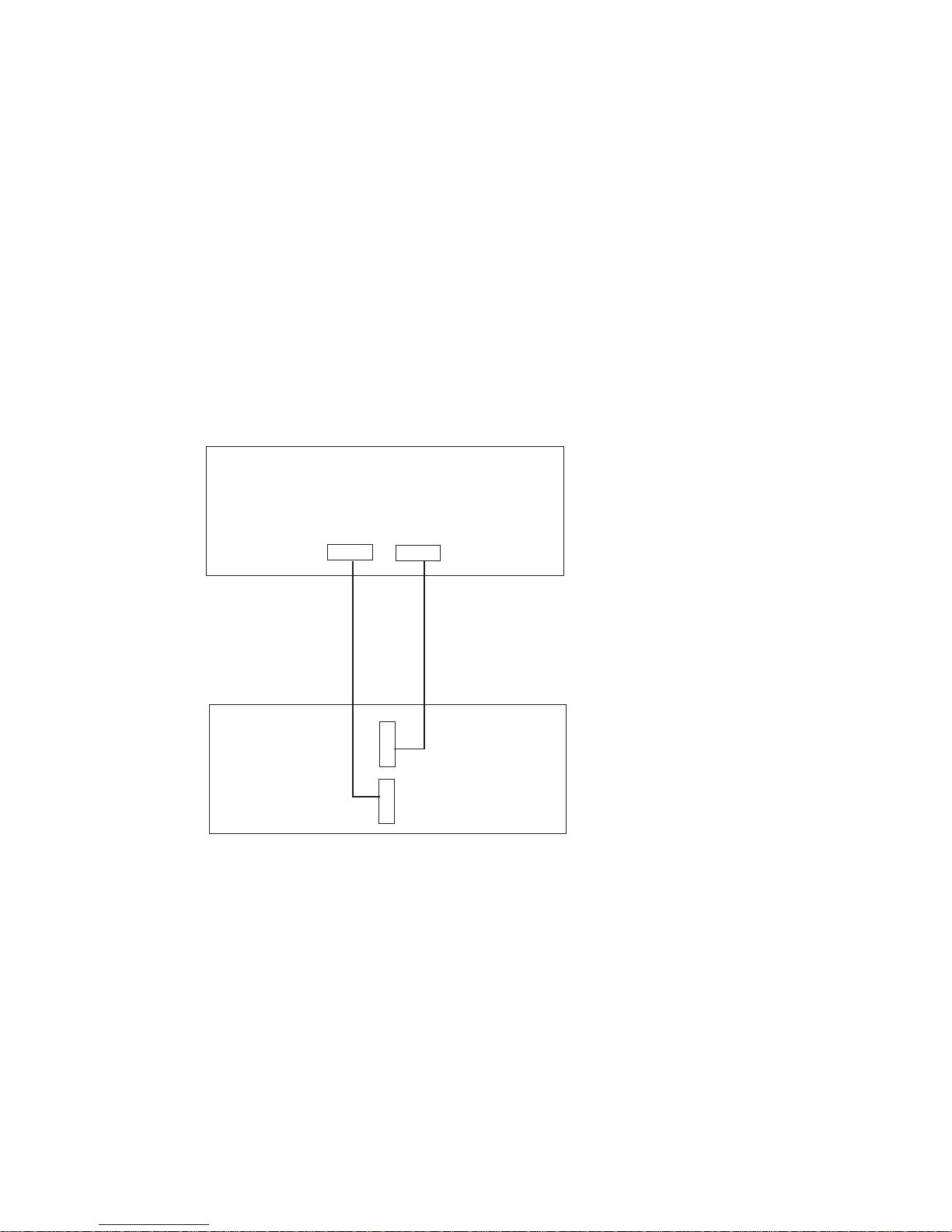
RIO Cabling
The following rules apply to RIO cable connections:
v I/O drawers 0 and 1 are connected using the first RIO loop, which uses RIO ports 0
and 1 on the CEC drawer.
v The primary I/O drawer must be installed and connected to RIO port 0 of the CEC
drawer. The connection must be made from RI0 port 0 of the CEC drawer to RIO
port 0 of the primary I/O drawer. This connection is required to make the primary
drawer the first drawer in the loop, which allows the firmware to initialize the system.
The following figures provide cabling examples for all valid cabling configurations.
Match your configuration to the correct figure and connect your RIO cables as shown.
CEC Drawer Attached to One I/O Drawer
R1
R0
R0
R1
Primary I/O
Drawer
CEC
Drawer
50 Service Guide
Page 69

CEC Drawer Attached to Two I/O Drawers
R1
R0
R0
R0
R1
R1
Primary I/O
Drawer
Secondary
I/O Drawer
CEC
Drawer
Chapter 1. Reference Information 51
Page 70

SPCN Cabling
The following figures provide cabling examples for all valid cabling configurations.
Match your configuration to the correct figure and connect your SPCN cables as shown.
CEC Drawer Attached to One I/O Drawer
JTAG
V/S COMM
V/S COMM
JTAG
Primary I/O
Drawer
CEC
Drawer
Note: The V/S COMM cable includes SPCN signals in addition to other signals.
52 Service Guide
Page 71

CEC Drawer Attached to Two I/O Drawers
J15
J15
J16
J16
Primary
I/O Drawer
Secondary
I/O Drawer
CEC
Drawer
V/S COMM
V/S COMM
Chapter 1. Reference Information 53
Page 72

System Cable Diagrams
The following diagrams show the system cable connections.
CEC Drawer Cable Diagram
Fan
Controller
Card
Power
LED
Fan 7
Fan 8
Power
Distribution
Board
System
Board
Power
Supply 1
3.3 V
3.3 V
3.3 V
Ground
Ground
5V
5V
Fan 1
Fan 2
Fan 5
CEC SPCN
CEC SPCN
Misc
Power
Misc
Power
Power
Supply 2 or
Cooling
Unit
Fan 3 Fan 4
Fan 6
Fan 9
J4
J6
J3
J2
J1
J5
J7
54 Service Guide
Page 73

Primary I/O Drawer Cable Diagram
Fan
Controller
Card
Power
Distribution
Board
DASD
Power
I/O Board
PCI Board
Op Panel
Op Panel
Power
Supply 1
3.3 V
3.3 V
Ground
Grd
5V
5V
Fan 1
Fan 2
Fan 5
CD-ROM
DASD 2
DASD 1
Term
Term
Optional
Media
Diskette
Diskette
Base SPCN
Base SPCN
JTAG
I/P
SCSI
V/S COMM
B
u
l
k
h
e
a
d
Power
Supply 2 or
Cooling
Unit
Fan 3 Fan 4
Fan 6
Fan 9
J4
J3
J2
J9
J4
J5
J30
J28
J2
J1
Media
Power
J6
Misc.
Power
J7
J21
J3
J5
Chapter 1. Reference Information 55
Page 74

Secondary I/O Drawer Cable Diagram
Fan
Controller
Card
Power
Distribution
Board
I/O Board
PCI Board
Op Panel
Op Panel
Power
Supply 1
3.3 V
3.3 V
Ground
Grd
5V
5V
Fan 1
Fan 2
Fan 5
Term
Optional
Media
Optional
Media
Base SPCN
SCSI
Base SPCN
I/P
Power
Supply 2 or
Cooling
Unit
Fan 3 Fan 4
Fan 6
Fan 9
J4
J3
J2
J2
J1
Media
Power
J6
Misc.
Power
J7
J21
J3
B
u
l
k
h
e
a
d
56 Service Guide
Page 75

DC Power Cable Routings
Chapter 1. Reference Information 57
Page 76

Specifications
This section contains specifications for the system. Individual sections are provided for
CEC drawer, rack, and the I/O drawer specifications.
CEC Drawer
The mechanical packaging, cooling, power supply, and environmental requirements for
the CEC drawer are shown in the following table:
Dimensions
Height 218 mm 8.58 in. (5 EIA Units)
Width 445 mm 17.5 in.
Depth 820 mm 32.3 in.
Weight
Minimum configuration 41 kg 90 lbs.
Maximum configuration 52 kg 115 lbs.
Electrical
Power source loading typical in
kVA
0.32
Power source loading maximum
in kVA
0.48
Voltage range (V ac) 200 to 240
Frequency (hertz) 50 or 60
Thermal output (typical) 1025 Btu/hr
Thermal output (maximum) 1536 Btu/hr
Power requirements (typical) 300 watts
Power requirements (maximum) 450 watts
Power factor 0.95
Inrush current¹ 40 amps
Maximum altitude² 2135 m (7000 ft.)
Temperature Requirements² Operating
10 to 40°C
(50 to 104°F)
Non-Operating
10 to 52°C
(50 to 125.6°F)
Humidity Noncondensing Operating Non-Operating
Without tape drive 8 to 80% 8 to 80%
With tape drive 20 to 80% 8 to 80%
Wet Bulb Requirements
Without tape drive 27°C (80.6°F) 27°C (80.6°F)
With tape drive 23°C (73°F) 27°C (80.6°F)
Noise Emissions³ Operating Idle
With H80 CEC Drawer only
L
WAd
5.8 bels 5.8 bels
L
pAm
N/A N/A
<L
pA>m
45 dBA 45 dBA
Impulsive or prominent discrete
tones
No No
58 Service Guide
Page 77

Noise Emissions³ Operating Idle
With H80 and Primary I/O
Drawer
L
WAd
6.2 bels 6.2 bels
L
pAm
N/A N/A
<L
pA>m
48 dBA 48 dBA
Impulsive or prominent discrete
tones
No No
Install/Air Flow Clearance Maintenance of proper service clearances should allow proper
air flow.
Service Clearance (See service clearances for the 7014 T00 Rack)
1. Inrush currents occur only at initial application of power, no inrush occurs during normal
power off-on cycle.
2. For altitudes above 915 meters, the maximum temperature limit is derated by 1 degree C for
every 137 meters of elevation above 915 meters.
3. See “Noise Emission Notes” on page 64 for definitions of noise emissions positions.
Chapter 1. Reference Information
59
Page 78

7014 Model T00 and T42 Rack
The mechanical packaging, cooling, power supply, and environmental requirements for
the rack are shown in the following table:
Dimensions
Height 1804 mm 71.0 in.
Capacity 36 EIA Units
With PDP - DC
only
1926 mm 75.8 in.
Width without
side panels
623 mm 24.5 in.
With side panels 644 mm 25.4 in.
Depth with rear
door
1042 mm 41.0 in.
RS/6000 T00 with
both doors
1098 mm 43.3 in.
pSeries T00 with
both doors
1147 mm 45.2 in.
Weight
Base Rack 244 kg 535 lbs
Full Rack¹ 816 kg 1795 lbs
.
Electrical² (sum specified values for
drawers or enclosures in rack)
DC Rack
Power source
loading maximum
in kVA³
8.4
AC Rack
Power source
loading maximum
in kVA (per PDB)⁴
4.8
Voltage range (V
ac)
200 to 240
Frequency (hertz) 50 or 60
Temperature
Requirements
(see specifications for drawers or enclosures)
Humidity
Requirements
(see specifications for drawers or enclosures)
Noise Emissions (see specifications for drawers or enclosures)
Clearances Front Back Left Right
Install/Air Flow Maintenance of a proper service clearance should allow proper air flow.
Service 915mm(36 in) 915mm(36 in) 915mm(36 in) 915mm(36 in)
60 Service Guide
Page 79

1. Configuration dependent, base rack weight plus the weight of the drawers mounted in the
rack. The rack can support up to a maximum weight of 35 lbs/EIA (Unit).
2. The total rack power should be derived from the sum of the power used by the drawers in the
rack.
3. The Power Distribution Panel (PDP) on the DC powered rack can hold up to eighteen (nine
per power source) 48 volt 20 to 50 amp circuit breakers (configuration dependent). Each
power source supports up to 8.4 kVA.
4. Each AC Power Distribution Bus (PDB) can supply 4.8 kVA. A rack can have up to four PDB’s
as required by the drawers mounted in the rack.
Chapter 1. Reference Information
61
Page 80

I/O Drawer
The mechanical packaging, cooling, power supply, and environmental requirements for
the I/O drawer are shown in the following table:
Dimensions
Height 218.0 mm 8.6 in.
Width 445.0 mm 17.5 in.
Depth 820.0 mm 32.3 in.
Weight
Minimum configuration 41 kg 90 lbs.
Maximum configuration 52 kg 115 lbs.
Electrical
Power source loading (typical in
kVA)
0.23
Power source loading
(maximum in kVA)
0.54
Voltage range 200 to 240 V ac
Frequency (hertz) 50 / 60
Thermal output (typical) 750 Btu/hr
Thermal output (maximum) 1750 Btu/hr
Power requirements (typical) 220 watts
Power requirements (maximum) 515 watts
Power factor 0.95
Inrush current³ 41 amps
Maximum altitude 2135 m (7000 ft.)
Temperature Requirements Operating
10 to 40°C
(50 to 104°F)
Non-Operating
10 to 52°C
(50 to 125.6°F)
Humidity (Noncondensing) Operating Non-Operating
Without tape drive 8 to 80% 8 to 80%
With tape drive 20 to 80% 20 to 80%
Wet Bulb Requirements
Without tape drive 27°C (80°F) 27°C (80°F)
With tape drive 23°C (73°F) 27°C (80°F)
Noise Emissions
1,2
Operating Idle
L
WAd
5.8 bels 5.8 bels
L
pAm
N/A N/A
<L
pA>m
45 dBA 45 dBA
Impulsive or prominent discrete
tones
No No
Clearances Front Back Left Right
Install/Air Flow Maintenance of a proper service clearance should allow proper
air flow.
Service (See “System Service Clearances” on page 65)
62 Service Guide
Page 81

1. See “Noise Emission Notes” on page 64 for definitions of noise emissions positions.
2. Noise emissions data are based on the following configuration: the drawer is mounted in a
T00 Rack and a power distribution unit.
3. Inrush currents occur only at initial application of power, no inrush occurs during normal
power off-on cycle.
Chapter 1. Reference Information
63
Page 82

Noise Emission Notes
1. L
WAd
is the declared (upper limit) sound power emission level for a production
series of machines.
2. L
pAm
is the mean value of the A-weighted sound pressure emission levels at the
operator position (if any) for a production series of machines.
3. <L
pA>m
is the mean value of the space-averaged A-weighted sound pressure
emission levels at the one-meter positions for a production series of machines.
4. N/A = Not Applicable (no operator position).
5. All measurements are made in accordance with ISO DIS 779 and reported in
conformance with ISO DIS 7574/4.
64 Service Guide
Page 83

System Service Clearances
The amount of space needed by the units during service is indicated by the dotted line
in the following figure.
For multiple racks placed side by side, the left and right clearances apply only to the
leftmost and rightmost rack.
Rack Configuration
2474 mm (97.4 in.)
3564 mm
(141 in.)
915 mm
(36 in.)
915 mm
(36 in.)
610 mm (24 in.)
610 mm (24 in.)
Front
Caster
Location
(4.8)121
(3.1)
80
Note: Rack units are large and heavy and are not easily moved. Because maintenance
activities require access at both the front and back, allow for extra room. The
footprint shows the radius of the swinging doors on the rack. The figure shows
the minimum space required.
Chapter 1. Reference Information 65
Page 84

Power Cables
To avoid electrical shock, a power cable with a grounded attachment plug is provided.
Use only properly grounded outlets.
Power cables used in the United States and Canada are listed by Underwriter’s
Laboratories (UL) and certified by the Canadian Standards Association (CSA). These
power cords consist of the following:
v Electrical cables, Type SVT or SJT
v Attachment plugs complying with National Electrical Manufacturers Association
(NEMA) 5-15P
″For 230 V operation in the United States use a UL listed cable set consisting of a
minimum 18 AWG, Type SVT or SJT three-conductor cable a maximum of 15 feet in
length, and a tandem blade, grounding type attachment plug rated at 15 A, 250 V.″
v Appliance couplers complying with International Electrotechnical Commission (IEC)
Standard 320, Sheet C13
Power cables used in other countries consist of the following:
v Electrical cables, Type HD21
v Attachment plugs approved by the appropriate testing organization for the specific
countries where they are used
″For units set at 230 V (outside of U.S.): use a cable set consisting of a minimum 18
AWG cable and grounding type attachment plug rated 15 A, 250 V. The cable set
should have the appropriate safety approvals for the country in which the equipment will
be installed and should be marked `HAR’.″
Refer to Chapter 10, “Parts Information” on page 471 to find the power cables that are
available.
66 Service Guide
Page 85

Service Inspection Guide
Perform a service inspection on the system when:
v The system is inspected for a maintenance agreement.
v Service is requested and service has not recently been performed.
v An alterations and attachments review is performed.
v Changes have been made to the equipment that may affect its safe operation.
v External devices with their own power cables have those cables attached.
If the inspection indicates an unacceptable safety condition, the condition must be
corrected before anyone can service the machine.
Note: The owner of the system is responsible to correct any unsafe conditions.
Perform the following checks:
1. Check the covers for sharp edges and for damage or alterations that expose the
internal parts of the system unit.
2. Check the covers for proper fit to the system unit. They should be in place and
secure.
3. Gently rock the system unit from side to side to determine if it is steady.
4. Set the power switch of the system unit to Off.
5. Remove the covers.
6. Check for alterations or attachments. If there are any, check for obvious safety
hazards, such as broken wires, sharp edges, or broken insulation.
7. Check the internal cables for damage.
8. Check for dirt, water, and any other contamination within the system unit.
9. Check the voltage label on the back of the system unit to ensure that it matches
the voltage at the outlet.
10. Check the external power cable for damage.
11. With the external power cable connected to the system unit, check for 0.1 ohm or
less resistance between the ground lug on the external power cable plug and the
metal frame.
12. Perform the following checks on each device that has its own power cables:
a. Check for damage to the power cord.
b. Check for the correct grounded power cable.
c. With the external power cable connected to the device, check for 0.1 ohm or
less resistance between the ground lug on the external power cable plug and
the metal frame of the device.
13. Install the covers.
Chapter 1. Reference Information 67
Page 86

68 Service Guide
Page 87

Chapter 2. Diagnostics Overview
Model H80 and Models 6H0 and 6H1 systems use an integrated set of software
diagnostic procedures to facilitate isolation of failing components and system
maintenance. This book, along with the
RS/6000 and
Eserver
pSeries Diagnostics
Information for Multiple Bus Systems
, are the basis of the diagnostic procedures for
Model H80 and Models 6H0 and 6H1 systems. In particular, the following sections in
this book are important for the trained service representative to understand and use
when isolating a failure on the system:
v Chapter 4, “Checkpoints” on page 137
v Chapter 5, “Error Code to FRU Index” on page 163
v Chapter 6, “Loading the System Diagnostics In Service Mode” on page 367
v Chapter 10, “Parts Information” on page 471
The manufacturer recommends that systems configured with 4 GB of memory or
greater have access toa4mmor8mmtape drive for submission of system dump
information if required. This function can be accomplished through locally attached or
network-attached devices, as appropriate.
Maintenance Analysis Procedures (MAPs)
Maintenance analysis procedures (MAPs) guide the trained service person through the
system. These MAPs are the entry point for all isolation and error-recovery procedures.
The MAPs are consistent with existing procedures and methods. The system uses a set
of integrated procedures, mentioned earlier, to which the MAPS are the primary entry
point.
The MAPS are as follows:
v Entry MAP
v Quick Entry MAP
v Problem Determination MAP
v Power MAP
v Minimum Configuration MAP
The Entry Map is the starting point for problem determination. The purpose of this MAP
is to quickly point to the appropriate MAP or service reference information either in this
book, or in the common book set, which includes the
RS/6000 and
Eserver
pSeries
Diagnostics Information for Multiple Bus Systems
and the
PCI Adapter Placement
Reference
.
The Quick Entry MAP is a subset of the Entry MAP and helps to save time for some
types of problems.
The Problem Determination MAP provides a structured analysis method to get an error
code if one is not provided by the customer, or if diagnostics cannot be loaded.
69
Page 88

The Power MAP deals with isolation of components to diagnose a power problem. The
nature of power problems can be related to powering on and down the system, or
power failures that can occur after power is turned on.
The Minimum Configuration MAP is used to locate defective components not found by
normal diagnostics or error-isolation methods. This MAP provides a systematic method
of isolation to the failing item or items.
Checkpoints
These servers use various types of checkpoints, error codes, and SRNs, which are
referred to throughout this book (primarily in Chapter 4, “Checkpoints” on page 137,
Chapter 5, “Error Code to FRU Index” on page 163, Chapter 6, “Loading the System
Diagnostics In Service Mode” on page 367, and Chapter 10, “Parts Information” on
page 471). These codes may appear in the service processor boot progress log, the
AIX error log, and the operator panel display. Understanding the definition and
relationships of these codes is important to the service personnel who are installing or
maintaining these servers.
Codes that can appear on the operator panel or in error logs are as follows:
Checkpoints
Checkpoints display in the operator panel from the time ac power (dc power in
a dc-powered system) is connected to the system until the AIX login prompt is
displayed after a successful operating system boot. These checkpoints have
the following forms:
8xxx 8xxx checkpoints display from the time ac power (dc power in a
dc-powered system) is connected to the system until the OK prompt is
displayed by the service processor on the operator panel display.
(Several 9xxx checkpoints are displayed just before the OK prompt
displays.)
9xxx 9xxx checkpoints are displayed by the service processor after the
power-on sequence is initiated. A system processor takes over control
when 91FF displays on the operator panel.
Exxx Exxx checkpoints indicate that a system processor is in control and is
initializing the system resources. Control is being passed to AIX when
E105 (normal mode boot) or E15B (service mode boot) displays on the
operator panel.
Note: Location code information may also display on the operator
panel during this time.
0xxx 0xxx codes are AIX checkpoints and configuration codes. Location
codes may also be shown on the operator panel display during this
time.
2xxx 2xxx codes are AIX checkpoints and configuration codes. Location
codes may also be shown on the operator panel display during this
time.
70 Service Guide
Page 89

Note: Certain checkpoints may remain in the display for long periods of time.
A spinning cursor is visible in the upper-right corner of the display
during these periods to indicate that system activity is continuing.
Error Codes
If a fault is detected, an 8-digit error code is displayed in the operator panel
display. A location may be displayed at the same time on the second line of
the display.
Checkpoints can become error codes if the system fails to advance past the
point at which the code was presented.
For a list of checkpoints, see Chapter 4, “Checkpoints” on page 137. Each
entry provides a description of the event and the recommended action if the
system fails to advance.
SRNs Service request numbers, in the form xxx-xxx or xxx-xxxx, may also be
displayed on the operator panel display and be noted in the AIX error log.
SRNs are listed in the
RS/6000 and
Eserver
pSeries Diagnostics Information
for Multiple Bus Systems
, order number SA38-0509.
FRU Isolation
For a list of error codes and recommended actions for each code, see Chapter 5, “Error
Code to FRU Index” on page 163. These actions can refer to Chapter 10, “Parts
Information” on page 471, Chapter 3, “Maintenance Analysis Procedures (MAPs)” on
page 75, or provide informational message and directions. If a replacement part is
indicated, direct reference is made to the part name. The respective AIX and physical
location codes are listed for each occurrence as required. For a list of locations codes,
see “AIX and Physical Location Code Reference Tables” on page 36.
To look up part numbers and view component diagrams, see Chapter 10, “Parts
Information” on page 471. The beginning of the chapter provides a parts index with the
predominant field replaceable units (FRUs) listed by name. The remainder of the
chapter provides illustrations of the various assemblies and components which make up
these servers.
Electronic Service Agent for the Eserver pSeries and RS/6000
Service support for your system can be enhanced through the use of the application
program, Electronic Service Agent. This application provides a number of advantages
for the systems customer, including automatic error reporting and analysis without
customer intervention. The Electronic Service Agent kit includes the
Electronic Service
Agent for
Eserver
pSeries and RS/6000
CD, order number LCD4–1060, which
contains documentation to help you set up and use Electronic Service Agent.
Chapter 2. Diagnostics Overview 71
Page 90

Using the Service Processor and Electronic Service Agent Features
The service processor and Electronic Service Agent features protect users against
unnecessary system downtime by advising support personnel (both internal and
external) of any unexpected changes in the system environment. In combination, the
two features provide a flexible solution to automated system maintenance.
Service Processor
The service processor runs on its own power boundary and continually monitors
hardware attributes, the AIX operating system, and the environmental conditions within
the system. Any system failure which prevents the system from returning to an
operational state (a fully functional AIX operating system) is reported by the service
processor. The service processor is controlled by firmware and does not require the AIX
operating system to be operational to perform its tasks. If any system failures are
detected, the service processor has the ability to take predetermined corrective actions.
The methods of corrective actions are:
v Surveillance
v Call home
v AIX operating system monitoring
Surveillance is a function in which the service processor monitors the system through
heartbeat
communication with the system firmware. The heartbeat is a periodic signal
that the firmware can monitor. During system startup, the firmware surveillance monitor
is automatically enabled to check for heartbeats from the firmware. If a heartbeat is not
detected within a default period, the service processor cycles the system power and
attempts to restart until the system either restarts successfully, or a predetermined retry
threshold is reached. In the event the service processor is unsuccessful in bringing the
system online (or in the event that the user asked to be alerted to any service
processor-assisted restarts), the system can call home to report the error.
The call home function can be initialized to call either a service center telephone
number, a customer administration center, or a digital pager telephone number. The
service processor can be configured to stop at the first successful call to any of the
numbers listed, or can be configured to call every number provided. If connected to the
service center, the service processor transmits the relevant system information (the
system’s serial number and model type) and service request number (SRN). If
connected to a digital pager service, the service processor inputs a customer voice
telephone number defined by the customer. An established sequence of digits or the
telephone number to a phone near the failed system could be used to signal a system
administrator to a potential system failure.
During normal operations, the service processor can also be configured to monitor the
AIX operating system. If AIX does not respond to the service processor heartbeat, the
service processor assumes the operating system is hung. The service processor can
automatically initiate a restart and, if enabled, initiate the call home function to alert the
appropriate people to the system hang. Enabling operating system surveillance also
enables AIX detect any service processor failures and report those failures to the
Electronic Service Agent application.
72 Service Guide
Page 91

Unlike the Electronic Service Agent, the service processor cannot be configured in a
client/server environment where one system can be used to manage all dial-out
functions for a set of systems.
Prior to installing the Electronic Service Agent feature, ensure that you have the latest
level of system firmware. You also need a properly configured modem. For more
information on configuring a modem, see “Modem Configuration Menu” on page 392.
Electronic Service Agent
The Electronic Service Agent is a software extension to the AIX operating system that
monitors the system while the AIX operating system is running. The Electronic Service
Agent monitors and analyzes all recoverable system failures, and, if needed, can
automatically place a service call to a service center (without user intervention).
The service center receives the machine type/serial number, host name, SRN, and a
problem description. The service center analyzes the problem report and, if warranted,
dispatches a service person to the customer site. The service center also determines if
any hardware components need to be ordered prior to the service person’s arrival.
The Electronic Service Agent code also gives the user the option to establish a single
system as the problem reporting server. A single system, accessible over the user
network, can be used as the central server for all the other systems on the local area
network (LAN) that are running the Electronic Service Agent application. If the
Electronic Service Agent application on a remote client decides a service request needs
to be placed, the client forwards the information to the Electronic Service Agent server
that dials the service center telephone number from its locally attached modem. In this
scenario, the user only needs to maintain a single analog line for providing call-out
capabilities for a large set of servers.
When used in a scalable parallel (SP) environment, a client/server type implementation
is configured. The Electronic Service Agent client code runs on each of the SP nodes.
The server component runs on the control workstation. In the event of any system
failures, the relevant information is transmitted to the control workstation through the
integrated Ethernet. After it has been alerted to the system failure, the control
workstation initiates actions to prepare and send the service request.
A modem is required for enabling automated problem reporting to the service center.
Configuration files for several types of modems are included as part of the Electronic
Service Agent package. Refer to “Modem Configuration Menu” on page 392 for more
information on configuring your modem.
Chapter 2. Diagnostics Overview 73
Page 92

74 Service Guide
Page 93

Chapter 3. Maintenance Analysis Procedures (MAPs)
This chapter contains maintenance analysis procedures (MAPs) for the system.
Entry MAP
Use the following table to determine your starting point. When possible, run online
diagnostics in service mode. Online diagnostics perform additional functions, compared
to standalone diagnostics. This ensures that the error state of the system is captured in
NVRAM for your use in fixing the problem. The AIX error log and SMIT are only
available when diagnostics are run from the hard drive.
Notes:
1. Licensed programs frequently rely on system information stored on the VPD module
on the operator panel assembly. If the MAPs indicate that the operator panel
assembly should be replaced, swap the VPD module from the old operator panel to
the new one. If recovery is not possible, notify the system owner that new keys for
licensed programs may be required.
2. If a network adapter is replaced, the network administrator must be notified so that
the client IP addresses used by the server can be changed. In addition, the
operating system configuration of the network controller may need to be changed in
order to enable system startup. Also check to ensure that any client or server that
addresses this system is updated.
3. If you are servicing an SP system, go to the Start-of-Call MAP 100 in the
SP
Systems Service Guide
.
4. If you are servicing a clustered Eserver system, go to the start of call MAP 100 in
the
Clustered
Eserver
Installation and Service Guide.
Symptom Starting Point
You have a problem that does not prevent the
system from booting and all the I/O drawer
operator panels are functional.
Go to the Fast Path MAP in the
Diagnostics
Information for Multiple Bus Systems
.
You have a problem that does not prevent the
system from booting and the secondary I/O
drawer operator panel is not functioning.
Replace the following parts one at a time in the
secondary I/O drawer with the non-functioning
operator panel.
1. Secondary I/O drawer operator panel.
2. Secondary I/O drawer operator panel cable.
You do not have a symptom. Go to MAP 0020 in the
Diagnostics Information
for Multiple Bus Systems
.
You have an SRN. Go to the Fast Path MAP in the
Diagnostics
Information for Multiple Bus Systems
.
The system stops and a 3-digit number is
displayed in the operator panel display.
Record SRN 101-xxx, where xxx is the 3-digit
number displayed in the operator panel display,
then go to the Fast Path MAP in the
Diagnostics Information for Multiple Bus
Systems
.
75
Page 94

Symptom Starting Point
The system stops and a 4-digit number
beginning with 0 or 2 is displayed in the
operator panel display.
Go to the Fast Path MAP in the
Diagnostics
Information for Multiple Bus Systems
.
All other symptoms. Go to “Quick Entry MAP”.
Quick Entry MAP
Quick Entry MAP Table of Contents
Problem Description Page No.
Service Actions 77
A Repeating Pattern of Error Code Data Appears on the Primary I/O Drawer
Operator Panel Display
77
OK Does Not Appear in the Primary I/O Drawer Operator Panel Display
Before Pressing the Power On Button
77
There is an 8-Digit Error Code 77
System Stops With an 8-Digit Number Displayed in the Primary I/O Drawer
Operator Panel Display
78
An Error Indication in the Secondary I/O Drawer Operator Panel Display 79
System Stops With a 4-Digit Number That Does Not Begin Witha0or2
Displayed
79
System Stops With a 3-Digit Number Displayed (888 sequence, see below) 80
There is a Display Problem (Distortion, Blurring,Etc.) 80
Power and Cooling Problems 80
An 888 sequence appears in Operator Panel Display 81
Other Symptoms or Problems 81
Attention: If you replace FRUs or perform an action and the problem is still not
corrected, go to “MAP 1540: Minimum Configuration” on page 113 unless otherwise
indicated in the tables.
If you replace FRUs and the problem is corrected, go to ″MAP 410: Repair Checkout″
in the
Diagnostics Information for Multiple Bus Systems
.
76 Service Guide
Page 95

Symptom Action
Service Actions
You have parts to exchange or a corrective
action to perform.
1. Go to the
Removal and Replacement
Procedures
.
2. Go to the
Repair Checkout Procedure
in the
Diagnostics Information for Multiple Bus
Systems
.
You need to verify that a part exchange or
corrective action corrected the problem.
Go to the
Repair Checkout Procedure
in the
Diagnostics Information for Multiple Bus
Systems
.
You need to verify correct system operation. Go to the
System Checkout Procedure
in the
Diagnostics Information for Multiple Bus
Systems
.
A Repeating Pattern of Error Code Data Appears on the Primary I/O Drawer Operator Panel
Display
A sequence of displays, each appearing for five
seconds, repeats continuously as follows: A
blank display, followed by an eight-digit error
code, followed by up to nine full panels of dump
data.
1. Record the 8-digit error code seen after the
five second blank display.
2. Reset the service processor, using the
pinhole reset.
3. Go to “Checkpoint and Error Code Index”
on page 165 with the error code you have
recorded.
OK Does Not Appear in the Primary I/O Drawer Operator Panel Display Before Pressing the
Power On Button
A bouncing or scrolling ball remains on the
primary I/O drawer operator panel display or
the primary I/O drawer operator panel display is
filled with dashes.
If an ASCII terminal is available, connect it to
the primary I/O drawer through serial port 1.
1. If the service processor menu is displayed:
a. Replace the primary I/O drawer operator
panel assembly. Refer to “Operator
Panel” on page 465.
b. Replace the primary I/O drawer
backplane. Refer to “I/O Drawer
Backplane Assembly” on page 447.
2. If the service processor menu is not
displayed, replace the primary I/O drawer
backplane. Refer to “I/O Drawer Backplane
Assembly” on page 447.
If an ASCII terminal is
not
available, replace the
following, one at a time.
1. Primary I/O drawer operator panel
assembly. Refer to “Operator Panel” on
page 465.
2. Primary I/O drawer backplane. Refer to “I/O
Drawer Backplane Assembly” on page 447.
You have a blank display on the primary I/O
drawer operator panel.
Go to “MAP 1520: Power” on page 89.
There is an 8-Digit Error Code
Chapter 3. Maintenance Analysis Procedures
77
Page 96

Symptom Action
You have an 8-digit error code in the form 10n1
xxxx and
n
is greater than the number of I/O
drawers in the system.
The failing drawer is drawer
n
. Look for the
drawer with the same value of n in its operator
panel, either in the form *0n or U0n. Substitute 2
for n when looking up the error code in
“Checkpoint and Error Code Index” on
page 165.
You have an 8-digit error code of the form 10n1
xxxx and two or more drawers have the same
drawer number.
Shut down the system and remove all but one
of the drawers with duplicate drawer numbers.
Refer to the steps in “MAP 1540: Minimum
Configuration” on page 113 for a procedure to
connect/disconnect I/O drawers. Attempt to
reboot the system.
1. If the system still fails, you have found the
failing drawer. Substitute 2 for n when
looking up the error code in Go to
“Checkpoint and Error Code Index” on
page 165.
2. If the system boots, shut down and add
another of the detached drawers back into
the system. Repeat steps 1 and 2 until the
failing drawer is isolated.
Note: As the system successfully boots,
duplicate drawer numbers are resolved into
unique drawer numbers.
You have an 8-digit error code. Go to “Checkpoint and Error Code Index” on
page 165.
System Stops With an 8-Digit Number Displayed in the Primary I/O Drawer Operator Panel
Display
You have an 8-digit error code of the form 10n1
xxxx and n is greater than the number of I/O
drawers in the system.
The failing drawer is drawer
n
. Look for the
drawer with the same value of n in its operator
panel, either in the form *0N or U0.n. Substitute
2 for n when looking up the error code in the
“Checkpoint and Error Code Index” on
page 165.
78 Service Guide
Page 97

Symptom Action
You have an 8-digit error code of the form 10n1
xxxx and two or more drawers have the same
drawer number.
Shut down the system and remove all but one
of the drawers with duplicate drawer numbers.
Refer to the steps in “MAP 1540: Minimum
Configuration” on page 113 for a procedure to
connect/reconnect I/O drawers. Attempt to
reboot the system.
1. If the system fails, you have found the
failing drawer. Substitute 2 for n when
looking up the error code in “Checkpoint
and Error Code Index” on page 165.
2. If the system boots, shut down and add
another of the detached drawers back into
the system. Repeat steps one and two until
the failing drawer is isolated.
Note: As the system successfully boots,
duplicate drawer numbers are resolved into
unique drawer numbers.
The system stops with an 8-digit error code
displayed when booting.
Go to “Checkpoint and Error Code Index” on
page 165.
An Error Indication in the Secondary I/O Drawer Operator Panel Display
A bouncing or scrolling ball remains on the
secondary I/O drawer operator panel display or
the secondary I/O drawer operator panel
display is filled with dashes.
Replace the following, one at a time:
1. Secondary I/O drawer backplane
Location: U0.2-P1
2. Secondary I/O drawer operator panel
assembly
Location: U0.2-L1
You have an 8-digit error code in the form 10n1
xxxx.
This is the failing drawer. If n is greater than the
number of I/O drawers in the system, substitute
2 for n when looking up the error code in
“Checkpoint and Error Code Index” on
page 165.
System Stops With a 4-Digit Number That Does Not Begin With 0 or 2 Displayed
Chapter 3. Maintenance Analysis Procedures
79
Page 98

Symptom Action
The system stops and a 4-digit checkpoint that
does not begin with 0 or 2 displayed in the
operator panel display or on the console.
If the number displayed begins with the
characters ″8″, ″9″, ″A″,or″B″, then go to
“Service Processor Checkpoints” on page 140.
If the number displayed is in the range
E1xx-EFFF, make note of any location code
that is displayed on the second line of the
operator panel. If the location code indicates a
card slot (for example, P1-I3), replace the card
in the indicated slot. If this does not correct the
problem, then go to “Firmware Checkpoints” on
page 147.
For all other numbers record SRN 101-xxxx,
where xxxx is the four-digit number displayed
in the operator panel, then go to the
Fast Path
MAP
in
RS/6000 and
Eserver
pSeries
Diagnostics Information for Multiple Bus
Systems
.
Note: If the operator panel displays two sets of
numbers, use the bottom set of numbers as the
error code.
System Stops With a 3-Digit Number Displayed (888 sequence, see below)
The system stops with a 3-digit error code. Add 101- to the left of the 3 digits to make an
SRN. Go to
Diagnostics Information for Multiple
Bus Systems
.
There is a Display Problem (Distortion, Blurring,Etc.)
All display problems.
1. If using a graphics display:
a. Go to the problem determination
procedures for the display.
b. If you do not find a problem, replace the
display adapter.
c. If you do not find a problem, suspect the
I/O planar. Go to “MAP 1540: Minimum
Configuration” on page 113.
2. If using an ASCII terminal:
a. Make sure that the ASCII terminal is
connected to S1.
b. If problems persist, go to the problem
determination procedures for the
terminal.
c. If you do not find a problem, suspect the
I/O planar. Go to “MAP 1540: Minimum
Configuration” on page 113.
Power and Cooling Problems
You cannot power on the system. Go to “MAP 1520: Power” on page 89.
80 Service Guide
Page 99

Symptom Action
The power on/off LED on an I/O drawer
operator panel does not come on or stay on.
(both the I/O drawer operator panel
power-on/off LED and the I/O drawer power
supply LEDs do not come on or stay on).
Go to “MAP 1520: Power” on page 89.
A rack or a rack mounted unit will not power on. Go to “MAP 1520: Power” on page 89.
You have a power problem. Go to “MAP 1520: Power” on page 89.
The system attention LED on the primary I/O
drawer operator panel is on and there is no
SRN displayed.
Go to “MAP 1520: Power” on page 89.
888 sequence in Operator Panel Display
An 888 sequence is displayed in the primary
I/O drawer operator panel display.
Go to the Fast Path MAP in the
Diagnostics
Information for Multiple Bus Systems
.
Other Symptoms or Problems
The operator panel displays OK. Fans and
blowers are off.
The service processor (SP) is ready. The
system is waiting for power-on.
All of the system POST indicators are displayed
on the system console, the system pauses and
then restarts. The term ″POST indicators″
refers to the device mnemonics (words memory,
keyboard, network, scsi, and speaker) that
appear on the system console during the
power-on self-test (POST).
Go to “Boot Problems and Concerns” on
page 159.
The system stops and all of the POST
indicators are displayed on the system console.
The term ″POST indicators″ refers to the device
mnemonics (words memory, keyboard, network,
scsi, and speaker) that appear on the system
console during the power-on self-test (POST).
Go to “MAP 1540: Minimum Configuration” on
page 113 to isolate the problem.
The system stops and the message STARTING
SOFTWARE PLEASE WAIT... is displayed on the
system console.
Go to Chapter 4, “Checkpoints” on page 137.
Chapter 3. Maintenance Analysis Procedures
81
Page 100

Symptom Action
The system does not respond to the password
being entered or the system login prompt is
displayed when booting in service mode.
1. If the password is being entered, or the
service mode boot is being initiated, on a
keyboard attached to the system, then the
keyboard or its controller may be faulty. In
this case, replace these parts in the
following order:
a. Keyboard
b. Primary I/O backplane, location:
U0.1-P1
2. If the password is being entered, or the
service mode boot is being initiated, from
an ASCII terminal, first insure that the
terminal is connected to S1 or S2. Use the
problem determination procedures for the
ASCII terminal.
If the problem persists, replace the primary
I/O backplane, location: U0.1-P1.
No codes are displayed on the operator panel
within a few seconds of turning on the system.
The operator panel displays OK before the
system is powered on.
Reseat the operator panel cable. If problem not
resolved, replace in order:
1. Operator panel assembly. Swap the VPD
module.
2. Primary I/O backplane. (See notes on 75.)
The SMS configuration list or boot sequence
selection menu shows more SCSI devices
attached to a controller/adapter than are
actually attached.
A device may be set to use the same SCSI bus
ID as the control adapter. Note the ID being
used by the controller/adapter (this can be
checked and/or changed via an SMS utility),
and verify that no device attached to the
controller is set to use that ID.
If settings do not appear to be in conflict:
1. Replace the SCSI cable.
2. Replace the device.
3. Replace the SCSI adapter
Note: In a ″twin-tailed″ configuration where
there is more than one initiator device (normally
another system) attached to the SCSI bus, it
may be necessary to use System Management
Services to change the ID of the SCSI
controller or adapter.
82 Service Guide
 Loading...