

Page 1

RS/6000 7043 Model 260 IBM
Service Guide
SA38-0554-00
Page 2

First Edition (October 1998)
The following paragraph does not apply to the United Kingdom or any country where
such provisions are inconsistent with local law: THIS PUBLICATION IS PROVIDED “AS
IS” WITHOUT WARRANTY OF ANY KIND, EITHER EXPRESS OR IMPLIED, INCLUDING,
BUT NOT LIMITED TO, THE IMPLIED WARRANTIES OF MERCHANTABILITY OR FITNESS
FOR A PARTICULAR PURPOSE. Some states do not allow disclaimer of express or implied
warranties in certain transactions, therefore, this statement may not apply to you.
This publication could include technical inaccuracies or typographical errors. Changes are
periodically made to the information herein; these changes will be incorporated in new editions
of the publication. The manufacturer may make improvements and/or changes in the
product(s) and/or the program(s) described in this publication at any time, without notice.
It is possible that this publication may contain reference to, or information about, products
(machines and programs), programming, or services that are not announced in your country.
Such references or information must not be construed to mean that these products,
programming, or services will be announced in your country. Any reference to a specific
licensed program in this publication is not intended to state or imply that you can use only that
licensed program. You can use any functionally equivalent program instead.
Requests for technical information about products should be made to your authorized reseller
or marketing representative.
International Business Machines Corporation 1998.. All rights reserved.
Note to U.S. Government Users -- Documentation related to restricted rights -- Use,
duplication or disclosure is subject to restrictions set forth is GSA ADP Schedule Contract with
IBM Corp.
Page 3

Contents
Communications Statements . . . . . . . . . . . . . . . . . . . . . . . . . . . . . .vii
Federal Communications Commission (FCC) Statement ............... vii
European Union (EU) Statement ............................ viii
International Electrotechnical Commission (IEC) Statement ............. viii
United Kingdom Telecommunications Safety Requirements ............. viii
Avis de conformité aux normes du ministère des Communications du Canada .. ix
Canadian Department of Communications Compliance Statement .......... ix
VCCI Statement . . . . . . . . . . . . . . . . . . . . . . . . . . . . . . . . . . . . . . . ix
Radio Protection for Germany ............................... ix
Safety Notices . . . . . . . . . . . . . . . . . . . . . . . . . . . . . . . . . . . . . . . xi
Electrical Safety . . . . . . . . . . . . . . . . . . . . . . . . . . . . . . . . . . . . . . . xi
Unit Emissions . . . . . . . . . . . . . . . . . . . . . . . . . . . . . . . . . . . . . . . .xii
Laser Safety Information ................................. xiii
Environmental Notices . . . . . . . . . . . . . . . . . . . . . . . . . . . . . . . . . .xv
Product Recycling and Disposal .............................. xv
Environmental Design . . . . . . . . . . . . . . . . . . . . . . . . . . . . . . . . . . .xv
About This Book ..................................... xvii
ISO 9000 . . . . . . . . . . . . . . . . . . . . . . . . . . . . . . . . . . . . . . . . . . xvii
Related Publications . . . . . . . . . . . . . . . . . . . . . . . . . . . . . . . . . . . xvii
Trademarks . . . . . . . . . . . . . . . . . . . . . . . . . . . . . . . . . . . . . . . . xvii
Chapter 1. Reference Information . . . . . . . . . . . . . . . . . . . . . . . . . . 1-1
System Unit Locations .................................. 1-1
System Cables . . . . . . . . . . . . . . . . . . . . . . . . . . . . . . . . . . . . . . . 1-9
Service Inspection Guide ................................ 1-10
Specifications . . . . . . . . . . . . . . . . . . . . . . . . . . . . . . . . . . . . . . 1-12
Power Cables . . . . . . . . . . . . . . . . . . . . . . . . . . . . . . . . . . . . . . 1-14
Chapter 2. Maintenance Analysis Procedures (MAPs) ............. 2-1
Quick Entry MAP ..................................... 2-2
MAP 1020: Problem Determination ........................... 2-9
MAP 1240: Memory Problem Resolution ....................... 2-15
MAP 1520: Power .................................... 2-23
MAP 1540: Minimum Configuration .......................... 2-31
Chapter 3. Error Code to FRU Index ........................ 3-1
Firmware/POST Error Codes .............................. 3-2
Bus SRN to FRU Reference Table .......................... 3-31
Preface iii
Page 4

Typical Boot Sequence for 7043 Model 260 ..................... 3-32
Checkpoints . . . . . . . . . . . . . . . . . . . . . . . . . . . . . . . . . . . . . . . 3-34
Boot Problems/Concerns . . . . . . . . . . . . . . . . . . . . . . . . . . . . . . . . 3-48
Chapter 4. Location Codes . . . . . . . . . . . . . . . . . . . . . . . . . . . . . . 4-1
Physical Location Codes ................................. 4-1
AIX Location Codes .................................... 4-3
AIX and Physical Location Code Reference Table .................. 4-6
Chapter 5. Loading the System Diagnostics ................... 5-1
Chapter 6. System Management Services ..................... 6-1
Graphical System Management Services ....................... 6-1
Config . . . . . . . . . . . . . . . . . . . . . . . . . . . . . . . . . . . . . . . . . . . . 6-4
MultiBoot . . . . . . . . . . . . . . . . . . . . . . . . . . . . . . . . . . . . . . . . . . 6-5
Utilities . . . . . . . . . . . . . . . . . . . . . . . . . . . . . . . . . . . . . . . . . . . 6-8
Password . . . . . . . . . . . . . . . . . . . . . . . . . . . . . . . . . . . . . . . . . 6-10
Error Log . . . . . . . . . . . . . . . . . . . . . . . . . . . . . . . . . . . . . . . . . 6-15
RIPL . . . . . . . . . . . . . . . . . . . . . . . . . . . . . . . . . . . . . . . . . . . . 6-16
SCSI ID . . . . . . . . . . . . . . . . . . . . . . . . . . . . . . . . . . . . . . . . . . 6-20
Firmware Update . . . . . . . . . . . . . . . . . . . . . . . . . . . . . . . . . . . . 6-21
Text-Based System Management Services ..................... 6-23
Display Configuration . . . . . . . . . . . . . . . . . . . . . . . . . . . . . . . . . . 6-25
MultiBoot Menu . . . . . . . . . . . . . . . . . . . . . . . . . . . . . . . . . . . . . 6-26
Utilities . . . . . . . . . . . . . . . . . . . . . . . . . . . . . . . . . . . . . . . . . . 6-29
Select Language . . . . . . . . . . . . . . . . . . . . . . . . . . . . . . . . . . . . 6-38
Chapter 7. Removal and Replacement Procedures ............... 7-1
Handling Static–Sensitive Devices ........................... 7-2
Procedure List . . . . . . . . . . . . . . . . . . . . . . . . . . . . . . . . . . . . . . . 7-3
Stopping the System Unit ................................ 7-4
Covers . . . . . . . . . . . . . . . . . . . . . . . . . . . . . . . . . . . . . . . . . . . 7-5
Processor and Memory Card Cover ......................... 7-10
Memory Cards . . . . . . . . . . . . . . . . . . . . . . . . . . . . . . . . . . . . . . 7-11
Memory Modules . . . . . . . . . . . . . . . . . . . . . . . . . . . . . . . . . . . . 7-14
Processor Card . . . . . . . . . . . . . . . . . . . . . . . . . . . . . . . . . . . . . 7-17
Adapters . . . . . . . . . . . . . . . . . . . . . . . . . . . . . . . . . . . . . . . . . 7-20
Internal Drives . . . . . . . . . . . . . . . . . . . . . . . . . . . . . . . . . . . . . . 7-22
Disk Drives . . . . . . . . . . . . . . . . . . . . . . . . . . . . . . . . . . . . . . . . 7-23
Configuration or Deconfiguration of Media Drives .................. 7-26
Battery . . . . . . . . . . . . . . . . . . . . . . . . . . . . . . . . . . . . . . . . . . 7-27
System Board . . . . . . . . . . . . . . . . . . . . . . . . . . . . . . . . . . . . . . 7-30
I/O Board . . . . . . . . . . . . . . . . . . . . . . . . . . . . . . . . . . . . . . . . . 7-33
Power Supply . . . . . . . . . . . . . . . . . . . . . . . . . . . . . . . . . . . . . . 7-35
iv Service Guide
Page 5

Operator Panel . . . . . . . . . . . . . . . . . . . . . . . . . . . . . . . . . . . . . 7-37
CEC Fan . . . . . . . . . . . . . . . . . . . . . . . . . . . . . . . . . . . . . . . . . 7-38
I/O Fan . . . . . . . . . . . . . . . . . . . . . . . . . . . . . . . . . . . . . . . . . . 7-39
Disk Drive Cage ..................................... 7-40
CD-ROM Drive, Tape Drive, Diskette Drive ..................... 7-43
Chapter 8. Parts Information . . . . . . . . . . . . . . . . . . . . . . . . . . . . . 8-1
Power Cables . . . . . . . . . . . . . . . . . . . . . . . . . . . . . . . . . . . . . . . 8-7
Appendix A. Service Processor Information ................... A-1
Service Processor Menus ................................ A-3
General User Menus ................................... A-4
Privileged User Menus .................................. A-6
Service Processor Functions and Features ..................... A-26
Service Processor Operational Phases ........................ A-39
Service Processor Procedures in Service Mode .................. A-41
Modem Configurations . . . . . . . . . . . . . . . . . . . . . . . . . . . . . . . . . A-42
Appendix B. Interpreting Firmware Error Codes ................. B-1
Index . . . . . . . . . . . . . . . . . . . . . . . . . . . . . . . . . . . . . . . . . . . . X-1
Reader's Comments — We'd Like to Hear From You ............... X-3
Preface v
Page 6

vi Service Guide
Page 7

Communications Statements
The following statement applies to this product. The statement for other products
intended for use with this product appears in their accompanying documentation.
Federal Communications Commission (FCC) Statement
Note: The 7043 Model 260 been tested and found to comply with the limits for a
Class B digital device, pursuant to Part 15 of the FCC Rules. These limits are
designed to provide reasonable protection against harmful interference in a
residential installation. This equipment generates, uses, and can radiate radio
frequency energy and, if not installed and used in accordance with the instructions,
may cause harmful interference to radio communications. However, there is no
guarantee that interference will not occur in a particular installation. If this equipment
does cause harmful interference to radio or television reception, which can be
determined by turning the equipment off and on, the user is encouraged to try to
correct the interference by one or more of the following measures:
Reorient or relocate the receiving antenna.
Increase the separation between the equipment and receiver.
Connect the equipment into an outlet on a circuit different from that to which the
receiver is connected.
Consult an authorized dealer or service representative for help.
Properly shielded and grounded cables and connectors must be used in order to
meet FCC emission limits. Proper cables and connectors are available from
authorized dealers. Neither the provider nor the manufacturer are responsible for
any radio or television interference caused by using other than recommended cables
and connectors or by unauthorized changes or modifications to this equipment.
Unauthorized changes or modifications could void the user's authority to operate the
equipment.
This device complies with Part 15 of the FCC Rules. Operation is subject to the
following two conditions: (1) this device may not cause harmful interference, and (2)
this device must accept any interference received, including interference that may
cause undesired operation.
Communications Statements vii
Page 8

Responsible Party:
International Business Machines Corporation
New Orchard Road
Armonk, New York 10504
Telephone: (919) 543-2193
Tested to Comply
With FCC Standards
FOR HOME OR OFFICE USE
European Union (EU) Statement
This product is in conformity with the protection requirements of EU Council Directive
89/336/EEC on the approximation of the laws of the Member States relating to
electromagnetic compatibility. The manufacturer cannot accept responsibility for any
failure to satisfy the protection requirements resulting from a non-recommended
modification of the product, including the fitting of option cards supplied by third
parties. Consult with your dealer or sales representative for details on your specific
hardware.
This product has been tested and found to comply with the limits for Class B
Information Technology Equipment according to CISPR 22 / European Standard EN
55022. The limits for Class B equipment were derived for typical residential
environments to provide reasonable protection against interference with licensed
communication devices.
International Electrotechnical Commission (IEC) Statement
This product has been designed and built to comply with IEC Standard 950.
United Kingdom Telecommunications Safety Requirements
This equipment is manufactured to the International Safety Standard EN60950 and
as such is approved in the UK under the General Approval Number
NS/G/1234/J/100003 for indirect connection to the public telecommunication network.
The network adapter interfaces housed within this equipment are approved
separately, each one having its own independent approval number. These interface
adapters, supplied by the manufacturer, do not use or contain excessive voltages.
An excessive voltage is one which exceeds 70.7 V peak ac or 120 V dc. They
interface with this equipment using Safe Extra Low Voltages only. In order to
viii Service Guide
Page 9
maintain the separate (independent) approval of the manufacturer's adapters, it is
essential that other optional cards, not supplied by the manufacturer, do not use
main voltages or any other excessive voltages. Seek advice from a competent
engineer before installing other adapters not supplied by the manufacturer.
Avis de conformité aux normes du ministère des Communications du
Canada
Cet appareil numérique de la classe B est conform à la norme NMB-003 du Canada.
Canadian Department of Communications Compliance Statement
This Class B digital apparatus complies with Canadian ICES-003.
VCCI Statement
The following is a summary of the VCCI Japanese statement in the box above.
This product is a Class B Information Technology Equipment and conforms to the
standards set by the Voluntary Control Council for Interference by Information
Technology Equipment (VCCI). This product is aimed to be used in a domestic
environment. When used near a radio or TV receiver, it may become the cause of
radio interference. Read the instructions for correct handling.
Radio Protection for Germany
Dieses Gerät ist berechtigt in Übereinstimmung mit dem deutschen EMVG vom
9.Nov.92 das EG–Konformitätszeichen zu führen.
Der Aussteller der Konformitätserklärung ist die IBM Germany.
Dieses Gerät erfüllt die Bedingungen der EN 55022 Klasse B.
Communications Statements ix
Page 10

x Service Guide
Page 11

Safety Notices
A
danger
death or serious personal injury.
A
caution
moderate or minor personal injury.
Electrical Safety
Observe the following safety instructions any time you are connecting or
disconnecting devices attached to the workstation.
DANGER
notice indicates the presence of a hazard that has the potential of causing
notice indicates the presence of a hazard that has the potential of causing
An electrical outlet that is not correctly wired could place hazardous
voltage on metal parts of the system or the devices that attach to the
system. It is the responsibility of the customer to ensure that the outlet
is correctly wired and grounded to prevent an electrical shock.
Before installing or removing signal cables, ensure that the power
cables for the system unit and all attached devices are unplugged.
When adding or removing any additional devices to or from the system,
ensure that the power cables for those devices are unplugged before
the signal cables are connected. If possible, disconnect all power
cables from the existing system before you add a device.
Use one hand, when possible, to connect or disconnect signal cables
to prevent a possible shock from touching two surfaces with different
electrical potentials.
During an electrical storm, do not connect cables for display stations,
printers, telephones, or station protectors for communication lines.
CAUTION:
This product is equipped with a three–wire power cable and plug for the user's
safety. Use this power cable with a properly grounded electrical outlet to avoid
electrical shock.
Preface xi
Page 12

DANGER
To prevent electrical shock hazard, disconnect the power cable from
the electrical outlet before relocating the system.
Unit Emissions
The unit-related emission value is equal to or lower than 70dB(A).
Der Geräuschpegel der Einheit ist kleiner oder gleich 70 db(A).
xii Service Guide
Page 13
Laser Safety Information
The optical drive in this system unit is a laser product. The optical drive has a label
that identifies its classification. The label, located on the drive, is shown below.
CLASS 1 LASER PRODUCT
LASER KLASSE 1
LUOKAN 1 LASERLAITE
APPAREIL A LASER DE CLASSE 1
IEC 825:1984 CENELEC EN 60 825:1991
The optical drive in this system unit is certified in the U.S. to conform to the
requirements of the Department of Health and Human Services 21 Code of Federal
Regulations (DHHS 21 CFR) Subchapter J for Class 1 laser products. Elsewhere,
the drive is certified to conform to the requirements of the International
Electrotechnical Commission (IEC) 825 (1st edition 1984) and CENELEC EN 60
825:1991 for Class 1 laser products.
CAUTION:
A class 3 laser is contained in the device. Do not attempt to operate the drive
while it is disassembled. Do not attempt to open the covers of the drive as it
is not serviceable and is to be replaced as a unit.
Class 1 laser products are not considered to be hazardous. The optical drive
contains internally a Class 3B gallium-arsenide laser that is nominally 30 milliwatts at
830 nanometers. The design incorporates a combination of enclosures, electronics,
and redundant interlocks such that there is no exposure to laser radiation above a
Class 1 level during normal operation, user maintenance, or servicing conditions.
Preface xiii
Page 14

xiv Service Guide
Page 15

Environmental Notices
Product Recycling and Disposal
This unit contains materials such as circuit boards and connectors with lead that
require special handling and disposal at end of life. Before this unit is disposed of,
these materials must be removed and recycled or discarded according to applicable
regulations. This manual contains specific information on batteries where applicable.
This product may contain nickel-cadmium and/or lithium batteries. The battery(s)
must be recycled or disposed of properly. Recycling facilities may not be available in
your area. In the United States, IBM has established a collection process for reuse,
recycling, or proper disposal of used sealed lead acid, nickel cadmium and nickel
metal hydride batteries and battery packs from IBM equipment. For information on
proper disposal of the nickel cadmium batteries in this product, please contact IBM at
1-800-426-4333. For information on battery disposal outside the United States,
contact your local waste disposal facility.
Environmental Design
The environmental efforts that have gone into the design of this system signify IBM's
commitment to improve the quality of its products and processes. Some of these
accomplishments include the elimination of the use of Class I ozone-depleting
chemicals in the manufacturing process and reductions in manufacturing wastes.
For more information, contact an IBM account representative.
Environmental Notices xv
Page 16

xvi Service Guide
Page 17

About This Book
This book provides maintenance information that is specific to the system unit,
adapters, and attached devices that do not have their own service information. This
book also contains Maintenance Analysis Procedures (MAPs) that are not common
with other systems. MAPs that are common to all systems are contained in the
RS/6000 Diagnostic Information for Multiple Bus Systems
This book is used by a service technician to diagnose and repair system failures.
This book assumes that the service technician has had previous training on the 7043
Model 260.
ISO 9000
ISO 9000 registered quality systems were used in the development and
manufacturing of this product.
Related Publications
The following publications provide additional information about your system unit:
.
IBM
The
The
The
The
Trademarks
AIX is a registered trademark of the International Business Machines
PowerPC is a trademark of the International Business Machines
Preface xvii
7043 Model 260 User's Guide
system unit, install, configure, and modify options, and solve minor problems.
IBM RS/6000 Diagnostic Information for Multiple Bus Systems
diagnostic information, service request numbers (SRNs), and failing function
codes (FFCs).
contains information to help users set up their
contains
IBM RS/6000 Adapter, Device, and Cable Information for Multiple Bus
Systems
system. This manual is intended to supplement the service information found in
the
your installation.
Corporation.
Corporation
contains information about adapters, devices, and cables for your
IBM RS/6000 Diagnostic Information for Multiple Bus Systems
Site and Hardware Planning Guide
contains information to help you plan
.
Page 18

xviii Service Guide
Page 19
Chapter 1. Reference Information
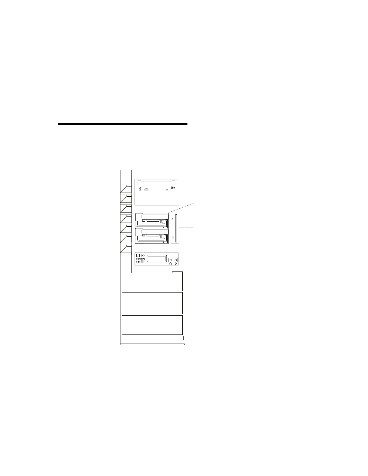
System Unit Locations
Front View with Media Door Off
CD-ROM Drive
Disk Drives
Diskette Drive
Operator Panel
Chapter 1. Reference Information 1-1
Page 20
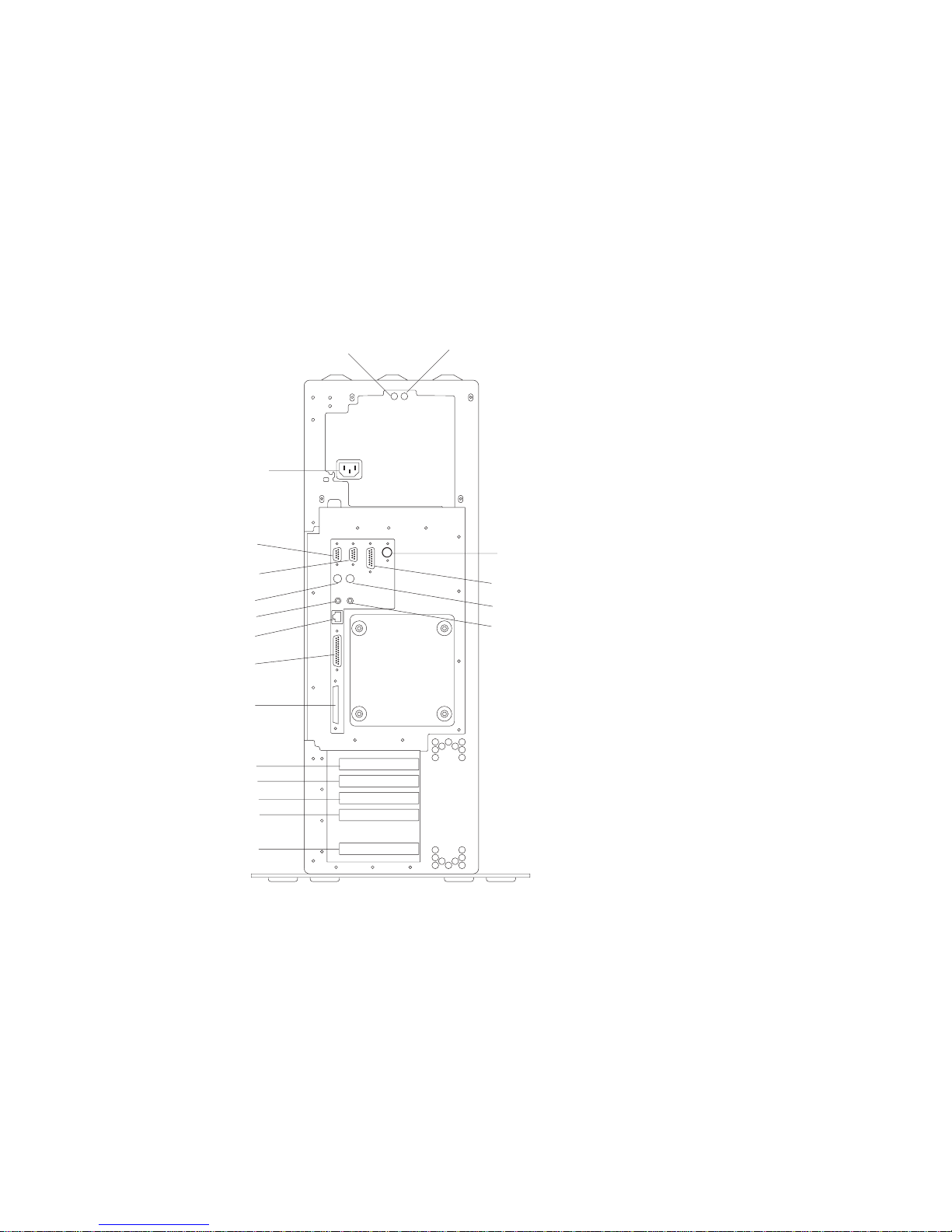
Rear View
1
3
2
13
14
15
10
12
16
19
4
5
8
17
18
7
6
9
11
1-2 Service Guide
Page 21

1 Power Supply LED
2 Power Supply Test Switch
3 Power Connector
4 Serial Connector S1
5 Serial Connector S2
6 AUI Ethernet Connector
7 Tablet Connector
8 Keyboard Connector
9 Mouse Connector
10 Audio Line Out
11 Audio Line In
12 RJ45 Ethernet Connector
13 Parallel Connector
14 External SCSI Connector
15 PCI Slot 5 (32-bit)
16 PCI Slot 4 (32-bit)
17 PCI Slot 3 (32-bit)
18 PCI Slot 2 (64-bit)
19 PCI Slot 1 (64-bit)
Chapter 1. Reference Information 1-3
Page 22
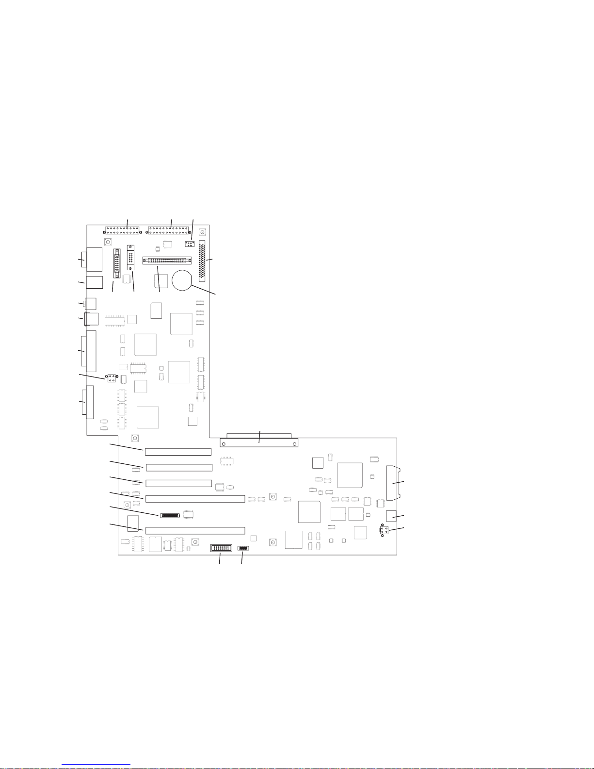
I/O Board Component Locations
J19
J16
J10
J23
J24
J26
J25
J27
J21
J28
J12
J13
J14
J8
J15
J9
J20
J18
J17
J7
J11
J4
J1
J2
J3
1-4 Service Guide
J6
J5
Page 23

J1 Operator panel power connector
J2 Operator panel audio connector
J3 PCI fan connector
J4 I/O board connector to system board
J5 VPD module connector
J6 ESP external connector
J7 Internal SCSI connector
J8, J9 64-bit PCI connectors
J10 CD ROM Audio
J11 Battery connector
J12, J13, J14 32-bit PCI connectors
J15 Service processor external connector
J16 Power connector
J17 Diskette drive connector
J18 Tablet connector
J19 Power connector
J20 AUI Ethernet connector
J21 Cec fan connector
J23 Serial port connector
J24 Keyboard/Mouse connector
J25 RJ45 Ethernet connector
J26 Audio in/out
J27 Parallel port connector
J28 External SCSI connector
Chapter 1. Reference Information 1-5
Page 24
SCSI IDs and Bay Locations
4
5
1
2
3
1 Bay D2 CD-ROM SCSI ID 1
2 Bay D3 Media device SCSI ID 0
3 Bay D1 Diskette drive Non-SCSI
4 Bay D4 Disk drive SCSI ID 9
5 Bay D5 Disk drive SCSI ID 8
Note: The SCSI bus ID's are the recommended values. Features installed at the
manufacturing site correspond to these IDs. Field installations may not comply with
these recommendations.
1-6 Service Guide
Page 25
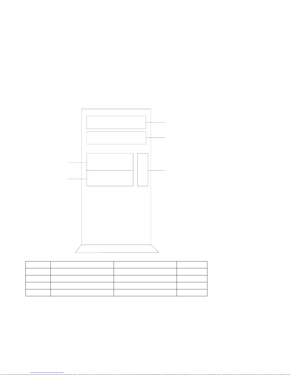
System Board Locations
J8
J6
J3
J2
J1
J1 System board connector to I/O board
J2 Memory card 2 connector
J3 Memory card 1 connector
J5 Power supply connector
J6 Processor card connector #2
J7 Power supply connector
J8 Processor card connector #1
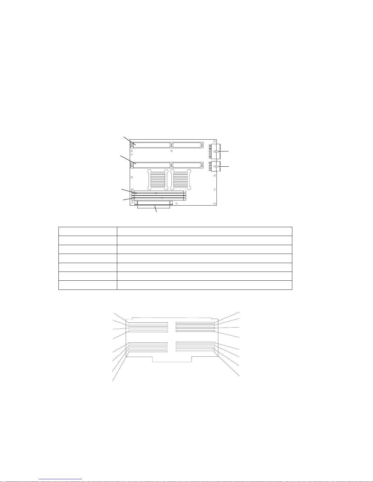
Memory Card Locations
Slot J15
Slot J13
Slot J11
Slot J9
Slot J7
Slot J5
Slot J3
Slot J1
J7
J5
Slot J16
Slot J14
Slot J12
Slot J10
Slot J8
Slot J6
Slot J4
Slot J2
Note: Memory modules must be installed in pairs and in the correct slot
configuration. (Slots J1 and J2, J3 and J4, J5 and J6, etc.)
Chapter 1. Reference Information 1-7
Page 26
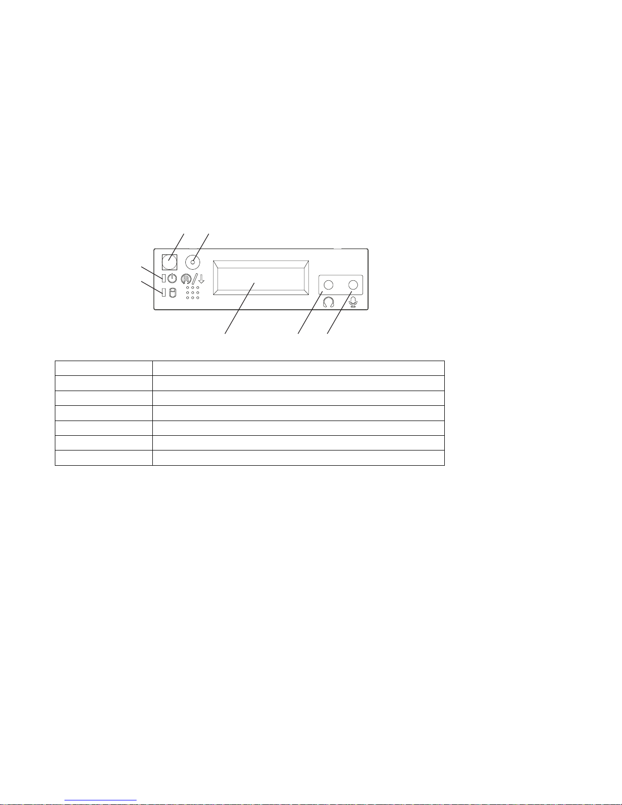
Operator Panel
1
2
3
4
1 Power On Switch
2 Reset Switch
3 Power On LED
4 Disk Drive Activity LED
5 Display
6 Headset Receptacle
7 Microphone Receptacle
6
5
7
1-8 Service Guide
Page 27
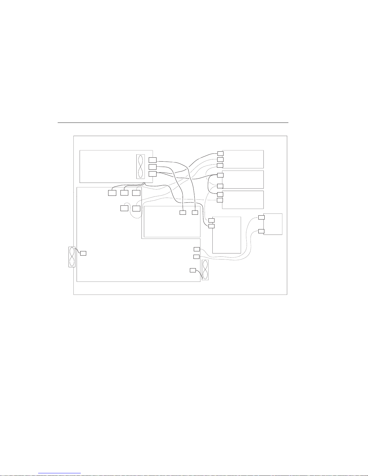
System Cables
Fan
Power SupplyPower
J21
Supply
Power
ROM
CD ROMCD
P6
Fan
SCSI
Disk
Disk
Drives
Drives
Audio
SCSI
Power
SCSI
Power
Data
Media
Media
Device
Device
Diskette
Power
Op
Op
Panel
Panel
Audio
P1
J10
J7
P2
P3
System BoardSystem
J7
Board
J5
J1
J2
J3
Fan
P4
P5
J17
I/O BoardI/O Board
Chapter 1. Reference Information 1-9
Page 28

Service Inspection Guide
Perform a service inspection on the system when:
The system is inspected for a maintenance agreement.
Service is requested and service has not recently been performed.
An alterations and attachments review is performed.
Changes have been made to the equipment that may affect the safe operation of
the equipment.
External devices with their own power cables have those cables attached.
If the inspection indicates an unacceptable safety condition, the condition must be
corrected before anyone can service the machine.
Note: The correction of any unsafe condition is the responsibility of the owner of the
system.
Perform the following checks:
1. Check the covers for sharp edges and for damage or alterations that expose the
internal parts of the system unit.
2. Check the covers for proper fit to the system unit. They should be in place and
secure.
3. Gently rock the system unit from side to side to determine if it is steady.
4. Set the power switch of the system unit to Off.
5. Remove the covers.
6. Check for alterations or attachments. If there are any, check for obvious safety
hazards such as broken wires, sharp edges, or broken insulation.
7. Check the internal cables for damage.
8. Check for dirt, water, and any other contamination within the system unit.
9. Check the voltage label on the back of the system unit to ensure that it matches
the voltage at the outlet.
10. Check the external power cable for damage.
11. With the external power cable connected to the system unit, check for 0.1 ohm
or less resistance between the ground lug on the external power cable plug and
the metal frame.
12. Perform the following checks on each device that has its own power cables:
a. Check for damage to the power cord.
1-10 Service Guide
Page 29

b. Check for the correct grounded power cable.
c. With the external power cable connected to the device, check for 0.1 ohm or
less resistance between the ground lug on the external power cable the
metal frame of the device.
13. Install the covers.
Chapter 1. Reference Information 1-11
Page 30

Specifications
The mechanical packaging, cooling, power supply, and environmental requirements
for the server is shown in the following:
Dimensions
With pedestal:
– Height - 615 mm (24.2 inches)
– Depth - 681 mm (26.8 inches)
– Width - 340 mm (13.4 inches)
Without pedestal:
– Height - 610 mm (24.0 inches)
– Depth - 681 mm (26.8 inches)
– Width - 221 mm (8.7 inches)
Weight
Configuration dependent
Operating Environment - Class B
Temperature - 16° to 32°C (60° to 90°F)
Humidity - 8% to 80% noncondensing
Maximum Altitude - 2135 m (7000 feet)
Power Source Loading
Typical EMC Configuration - 0.3 kVA
Maximum - 0.5 kVA
Power Requirements
Typical - 275 watts
Maximum - 640 watts
1-12 Service Guide
Page 31

Power Factor
0.89 - 0.98
Operating Voltage
100 to 127V ac; 50 to 60 Hz
200 to 240V ac; 50 to 60 Hz
Heat Output (Maximum)
Typical - 400 BTU/hr
Maximum - 794 BTU/hr
Acoustics
6.0 Bels operating
5.5 Bels idle
Chapter 1. Reference Information 1-13
Page 32

Power Cables
To avoid electrical shock, a power cable with a grounded attachment plug is
provided. Use only properly grounded outlets.
Power cables used in the United States and Canada are listed by Underwriter's
Laboratories (UL) and certified by the Canadian Standards Association (CSA).
These power cords consist of:
Electrical cables, Type SVT or SJT.
Attachment plugs complying with National Electrical Manufacturers Association
(NEMA) 5-15P. That is:
"For 115 V operation, use a UL listed cable set consisting of a minimum 18 AWG,
Type SVT or SJT three-conductor cord a maximum of 15 feet in length and a parallel
blade, grounding type attachment plug rated at 15 A, 125 V."
"For 230 V operation in the United States use a UL listed cable set consisting of a
minimum 18 AWG, Type SVT or SJT three-conductor cable a maximum of 15 feet in
length, and a tandem blade, grounding type attachment plug rated at 15 A, 250 V."
Appliance couplers complying with International Electrotechnical Commission
(IEC) Standard 320, Sheet C13.
Power cables used in other countries consist of the following:
Electrical cables, Type HD21.
Attachment plugs approved by the appropriate testing organization for the
specific countries where they are used.
"For units set at 230 V (outside of U.S.): use a cable set consisting of a minimum 18
AWG cable and grounding type attachment plug rated 15 A, 250 V. The cable set
should have the appropriate safety approvals for the country in which the equipment
will be installed and should be marked HAR'."
Refer to Chapter 8, “ Parts Information” on page 8-1 to find the power cables that
are available.
1-14 Service Guide
Page 33

Chapter 2. Maintenance Analysis Procedures (MAPs)
Note: When possible, run Online Diagnostics in Service Mode. Online Diagnostics
perform additional functions, compared to Standalone Diagnostics. This ensures that
the error state of the system is captured in NVRAM for your use in fixing the
problem. The AIX error log and SMIT are only available when diagnostics are run
from the hard drive.
Notes:
1. If more than eight digits are displayed in the operator panel, use only the first
eight digits to find the error in the tables. The digits that display beyond the first
eight digits are location codes that can assist you in diagnosing the problem. See
Chapter 4, “Location Codes” on page 4-1.
2. Licensed programs frequently rely on network configuration, and system
information stored on the VPD on the operator panel control assembly. If the
MAPs indicate that the Operator Panel Control Assembly should be replaced,
swap the VPD from the old operator panel to the new one. If the old VPD
module has to be replaced call technical support for recovery instructions. If
recovery is not possible, notify the system owner that new keys for licensed
programs may be required.
3. If a network adapter, or the I/O board is replaced, the network administrator must
be notified so that the client IP addresses used by the server can be changed.
In addition, the operating system configuration of the network controller may
need to be changed in order to enable system startup. Also check to ensure that
any client or server that addresses this system is updated.
Chapter 2. Maintenance Analysis Procedures 2-1
Page 34

Quick Entry MAP
Use the following table to determine your starting point.
Quick Entry MAP Table of Contents
Problem Description Page No.
Service Actions 2-3
System Stops With an 8-Digit Number Displayed 2-3
System Stops With a 4-Digit Number Displayed 2-3
System Stops With a 3-Digit Number Displayed 2-3
System Stops or Hangs With Alternating Numbers Displayed in the Operator
Display Panel.
There Appears to be a Display Problem (Distortion, Blurring,Etc.) 2-4
Power and Cooling Problems 2-4
Flashing 888 in Operator Panel Display 2-4
Other Symptoms or Problems 2-5
You Cannot Find the Symptom in this Table 2-8
2-4
2-2 Service Guide
Page 35

Symptom Action
Service Actions
You have parts to exchange or a corrective
action to perform.
1. Go to the
Procedures
2. Go to "MAP 410: Repair Checkout" in the
Removal and Replacement
.
IBM RS/6000 Diagnostic Information for
Multiple Bus Systems
You need to verify that a part exchange or
corrective action corrected the problem.
You need to verify correct system operation. Go to "MAP 410: Repair Checkout" in the
Go to "MAP 410: Repair Checkout" in the
RS/6000 Diagnostic Information for Multiple Bus
Systems
.
.
RS/6000 Diagnostic Information for Multiple Bus
System Stops With An 8-Digit Number Displayed
The system stops with an 8-digit error code
displayed in the operator panel display or on the
console.
System Stops With An 4-Digit Number Displayed
The system stops and a 4-digit number is
displayed in the operator panel display or on the
console.
Systems
Record the error code. Go to Chapter 3, “Error
Code to FRU Index” on page 3-1.
If the number displayed begins with the
character "E0xx" then go to “SP Checkpoints”
on page 3-34.
If the number displayed begins with the
characters "E1xx-EFFF", make note of any
location code that is displayed on the second
line of the operator panel. If the location code
indicates a card slot (eg. P2-I3), replace the
card in the indicated slot. If this does not correct
the problem, then go to “Firmware Checkpoints”
on page 3-37.
For all other numbers record SRN 101-xxx,
where xxx is the last three digits of the four-digit
number displayed in the operator panel, then go
to the Fast Path MAP in the
.
IBM RS/6000
Diagnostic Information for Multiple Bus Systems
Note: If the operator panel displays 2 sets of
numbers, use the bottom set of numbers as the
error code.
IBM
IBM
.
System Stops With An 3-Digit Number Displayed
The system stops with an 3-digit number
displayed in the operator panel display or on the
console.
Chapter 2. Maintenance Analysis Procedures 2-3
Record SRN 101-xxx, where xxx is the last
three digits of the four-digit number displayed in
the operator panel, then go to the Fast Path
MAP in the
for Multiple Bus Systems
IBM RS/6000 Diagnostic Information
.
Page 36

Symptom Action
System Stops or Hangs With Alternating Numbers Displayed in the Operator Display Panel
The operator panel display alternates between
the code "E1FD" and another "Exxx" code.
The operator panel display alternates between
the codes "E1DE" and "E1AD".
Display Problem (Blank, Distortion, Blurring, Etc.).
All display problems. 1. If using a graphics display:
Record both codes. Go to "E1FD" in “Firmware
Checkpoints” on page 3-37.
Record both codes. Go to "E1DE" in “Firmware
Checkpoints” on page 3-37.
a. Go to the
Procedures
b. If you do not find a problem, replace the
display adapter.
c. If you do not find a problem, suspect the
I/O board. Go to “MAP 1540: Minimum
Configuration” on page 2-31.
2. If the problem is with the ASCII terminal:
a. Make sure that the ASCII terminal is
connected to S1.
b. If problems persist, go to the
Determination Procedures
terminal.
c. If you do not find a problem,replace the
service processor.
d. If you do not find a problem, suspect the
I/O board. Go to “MAP 1540: Minimum
Configuration” on page 2-31.
Problem Determination
for the display.
Problem
for the
Power and Cooling Problems
The power LEDs on the operator panel and the
power supply do not start flashing within 30
seconds of AC power application.
The power LEDs on the operator panel and the
power supply do not come on or stay on.
The power LEDs on the operator panel and the
power supply come on and stay on but the
system does not power on.
The cooling fan(s) do not come on or come on
but do not stay on.
Flashing 888 in Operator Panel Display
888 is displayed is displayed in the operator
panel.
2-4 Service Guide
Go to “MAP 1520: Power” on page 2-23.
Go to “MAP 1520: Power” on page 2-23.
Go to “MAP 1520: Power” on page 2-23.
Go to “MAP 1520: Power” on page 2-23.
Go to the Fast Path MAP in the
IBM RS/6000
Diagnostic Information for Multiple Bus Systems
.
Page 37

Symptom Action
Other Symptoms or Problems
You have OK displayed. The service processor is ready. Go to "MAP
0020: Problem Determination Procedure" in the
IBM RS/6000 Diagnostic Information for Multiple
Bus Systems
You have STBY displayed. The Service Processor is ready. The system
was shutdown by the operating system and is
still powered on. This condition can be
requested by a privileged system user with no
faults. See SP error log for possible operating
system fault indications.
The system POST indicators are displayed on
the system console, the system pauses and
then restarts. The term "POST indicators" refer
to the icons (graphic display) or device
mnemonics (ASCII terminal) that appear during
the power-on self-test (POST).
The system stops and POST indicators are
displayed on the system console. The term
"POST indicators" refer to the icons (graphic
display) or device mnemonics (ASCII terminal)
that appear during the power-on self-test
(POST).
The system stops and the message "STARTING
SOFTWARE PLEASE WAIT..." is displayed on
Go to “Boot Problems/Concerns” on page 3-48.
Go to “MAP 1540: Minimum Configuration” on
page 2-31 to isolate the problem.
Go to “Checkpoints” on page 3-34.
.
ASCII terminal, the boot indicator ( ) is
displayed on a graphics terminal.
Chapter 2. Maintenance Analysis Procedures 2-5
Page 38

Symptom Action
The system does not respond to the password
being entered or the system login prompt is
displayed when booting in service mode.
Verify that the password is being entered from
the ASCII terminal or keyboard defined as the
system console. If so, then the keyboard or its
controller may be faulty.
1. If entering the password from the keyboard
which is attached to the system, replace the
keyboard. If replacing the keyboard does not
fix the problem, replace the I/O board. (See
notes on 2-1.)
2. If entering the password from a keyboard
which is attached to a ASCII terminal, use
the Problem Determination Procedures for
the ASCII terminal. Make sure the ASCII
terminal is connected to S1. Replace the
I/O board if these procedures do not reveal
a problem.
3. If the problem is fixed, go to "MAP 410:
Repair Checkout" in the
Diagnostic Information for Multiple Bus
Systems
“MAP 1540: Minimum Configuration” on
page 2-31 to isolate the problem.
No codes are displayed on the operator panel
within a few seconds of turning on the system.
The operator panel is blank before the system is
powered on.
Reseat the operator panel cable. If the problem
is not resolved, replace these parts in the
following order:
1. Operator panel assembly. Update the VPD
information in the new operator panel.
2. I/O board (See notes on 2-1.)
3. If the problem is fixed, go to "MAP 410:
Repair Checkout" in the
Diagnostic Information for Multiple Bus
Systems
“MAP 1540: Minimum Configuration” on
page 2-31 to isolate the problem.
IBM RS/6000
. If the problem persists, go to
IBM RS/6000
. If the problem persists, go to
2-6 Service Guide
Page 39

Symptom Action
The SMS configuration list or Boot sequence
selection menu shows more SCSI devices
attached to a controller/adapter than are actually
attached.
The System Management Services menu is
displayed.
You have a problem that does not prevent the
system from booting.
You have an SRN. Go to the Fast Path MAP in the
A device may be set to use the same SCSI bus
ID as the control adapter. Note the ID being
used by the controller/adapter (this can be
checked and/or changed via an SMS utility), and
verify that no device attached to the controller is
set to use that ID.
If settings do not appear to be in conflict:
1. Replace the SCSI cable.
2. Replace the device.
3. Replace the SCSI adapter (or I/O board if
connected to one of the two integrated SCSI
controllers on the I/O board). (See notes on
2-1 if the I/O board is replaced.)
Note: In a "Twin-tailed" configuration where
there is more than one initiator device
(normally another system) attached to
the SCSI bus, it may be necessary to
change the ID of the SCSI controller or
adapter with the System Management
Services.
The device or media you are attempting to boot
from may be faulty.
1. Check the SMS error log for any errors. To
check the error log:
a. Choose error log
b. If an error is logged, check the time
stamp.
c. If the error was logged during the
current boot attempt,record it.
d. Look up the error in “Checkpoints” on
page 3-34 and do the listed action.
e. If no recent error is logged in the error
log, continue to the next step below.
2. Try to boot from an alternate boot device
connected to the same controller as the
original boot device. If the boot succeeds,
replace the original boot device (for
removable media devices try the media first.
3. Go to “MAP 1540: Minimum Configuration”
on page 2-31.
Go to the Fast Path MAP in the
Diagnostic Information for Multiple Bus Systems
Diagnostic Information for Multiple Bus Systems
IBM RS/6000
.
IBM RS/6000
.
Chapter 2. Maintenance Analysis Procedures 2-7
Page 40

Symptom Action
You suspect a cable problem. See the
Cable Information for Multiple Bus Systems
You do not have a symptom. Go to MAP 0020 in the
Information for Multiple Bus Systems
You do not have a determined symptom. Go to “MAP 1020: Problem Determination” on
page 2-9.
You Cannot Find the Symptom in this Table
All other problems. Go to “MAP 1020: Problem Determination” on
page 2-9.
IBM RS/6000 Adapter, Device, and
.
IBM RS/6000 Diagnostic
.
2-8 Service Guide
Page 41

MAP 1020: Problem Determination
Purpose of This MAP
Use this MAP to get an error code if you were not provided one by the customer or
you are unable to load diagnostics. If you are able to load the diagnostics, go to
MAP 0020 in the
The Service Processor may have recorded one or more symptoms in its error log. It
is a good idea to examine that error log before proceeding (see Service Processor
System Information Menu).
Be prepared to record code numbers and use those numbers in the course of
analyzing a problem. Go to “Step 1020-1” on page 2-11.
The Service Processor may have been set by the user to monitor server operations
and to attempt recoveries. You may wish to disable these actions while you diagnose
and service the system. If the system was set up according to the recommendations
of the User's Guide, all the settings of the Service Processor (except Language)
were saved by using the SAVE/RESTORE HARDWARE MAINTENANCE POLICIES
Service Aid. You may use that same Service Aid to restore the settings at the end of
your service action.
Just in case the Service Processor settings were not saved by the user, if you
disable them, you should make notes of their current settings for restoration before
you leave.
IBM RS/6000 Diagnostic Information for Multiple Bus Systems
.
Chapter 2. Maintenance Analysis Procedures 2-9
Page 42

In addition to the parameters in the table below, you may wish to disconnect the
modem to prevent incoming signals that could cause the system to power on.
Following are the Service Processor settings of your interest. The Service Processor
menus are described in “Service Processor Menus” on page A-3.
Surveillance From the Service Processor Setup Menu, go to
the Surveillance Setup Menu and disable
surveillance.
Unattended Start From the Service Processor System Power
Control Menu, disable unattended start mode.
Reboot Policy From the System Power Control Menu, go to
the Reboot/Restart Policy Setup Menu and set:
1. Number of reboot attempts to 0 (zero)
2. Use OS-Defined restart policy to No
3. Enable supplemental restart policy to No.
Call Out From the Call-In/Call-Out Setup Menu, go to the
Serial Port Selection Menu and disable call-out
on both serial ports.
Another feature that could disrupt a service action by powering the system on is an
AIX function called "Timed Power-On". If you think it should be turned off during your
service action, refer to the "System Power-On Methods" in the System User's Guide:
Operating System and Devices (order number SC23-4126).
2-10 Service Guide
Page 43

Step 1020-1
The following steps analyze a failure to load the diagnostic programs.
Note: You are asked questions regarding the operator panel display. You are also
asked to perform certain actions based on displayed POST indicators.
Please be observant of these conditions.
1. Insert the diagnostic CD-ROM into the CD-ROM drive.
2. Turn the power off.
3. Turn the power on.
4. When the keyboard indicator is displayed (the word keyboard on an ASCII
terminal or the keyboard icon on a graphical display), press the F5 key on the
directly-attached keyboard or the number 5 key on an ASCII terminal.
5. Enter a password, if requested.
6. Wait until the diagnostics are loaded or the system appears to stop.
7. Find your symptom in the following table; then follow the instructions given in the
Action column.
Symptom Action
The diskette LED is blinking rapidly, or EIEA or
EIEB is displayed on the operator panel.
The system stops with a prompt to enter a
password.
The diagnostic operating instructions are
displayed.
The system login prompt is displayed. You may not have pressed the correct key or
The flash EPROM data is corrupted. The
recovery procedure for the flash EPROM should
be executed. See “Firmware Recovery” on
page 6-22.
Enter the password. You are not allowed to
continue until a correct password has been
entered. When you have entered a valid
password go to the beginning of this table and
wait for one of the other conditions to occur.
Go to MAP 0020 in the
Information for Multiple Bus Systems
you may not have pressed the key soon enough
when you were to indicate a Service Mode IPL
of the diagnostic programs. If this was the case
start over at the beginning of this Step.
Note: Perform the systems shutdown
procedure before turning off the system.
If you are sure you pressed the correct key in a
timely manner, go to “Step 1020-2” on
page 2-13.
IBM RS/6000 Diagnostic
.
Chapter 2. Maintenance Analysis Procedures 2-11
Page 44

Symptom Action
The system does not respond when the
password is entered.
The system stopped and a POST indicator is
displayed on the system console and an
eight-digit error code is not displayed.
The system stops and a 4-digit number is
displayed in the operator panel display.
Go to “Step 1020-2” on page 2-13.
If the POST indicator represents:
memory, record error code M0MEM002.
keyboard, record error code M0KBD000.
SCSI, record error code M0CON000.
network, record error code M0NET000.
speaker (audio), record error code
M0BT0000.
Go to “Step 1020-3” on page 2-13.
If the number displayed begins with the
character "E0xx" then go to “SP Checkpoints”
on page 3-34. or "E1xx-EFFF" then go to
“Firmware Checkpoints” on page 3-37.
For all other numbers record SRN 101-xxx,
where xxx is the last three digits of the four-digit
number displayed in the operator panel, then go
to the Fast Path MAP in the
IBM RS/6000
Diagnostic Information for Multiple Bus Systems
Note: If the operator panel displays 2 sets of
numbers, use the bottom set of numbers as the
error code.
The System Management Services is displayed. Go to“Step 1020-4” on page 2-14.
All other symptoms. If you were directed here from the Entry MAP,
go to “MAP 1540: Minimum Configuration” on
page 2-31. Otherwise, find the symptom in the
“Quick Entry MAP” on page 2-2.
.
2-12 Service Guide
Page 45

Step 1020-2
There is a problem with the keyboard.
Find the type of keyboard you are using in the following table; then follow the
instructions given in the Action column.
Keyboard Type Action
Type 101 keyboard (U.S.). Identify by the size of
the Enter key. The Enter key is in only one
horizontal row of keys.
Type 102 keyboard (W.T.). Identify by the size of
the Enter key. The Enter key extends into two
horizontal rows.
Type 106 keyboard. (Identify by the Japanese
characters.)
ASCII terminal keyboard Go to the documentation for this type of ASCII
Record error code M0KBD001; then go to
“Step 1020-3.”
Record error code M0KBD002; then go to
“Step 1020-3.”
Record error code M0KBD003; then go to
“Step 1020-3.”
terminal and continue problem determination.
Step 1020-3
Take the following actions:
1. Find the eight-digit error code in Chapter 3, “Error Code to FRU Index” on
page 3-1.
Note: If the eight-digit error code is not listed in Chapter 3, “Error Code to FRU
Index,” look for it in the following:
Any supplemental service manual for the device
The diagnostic problem report screen for additional information
The Service Hints service aid
The CEREADME file (by using the Service Hints service aid). Note: Service
aids can be found in Diagnostic Information for Multiple Bus Systems.
2. Perform the action listed.
Chapter 2. Maintenance Analysis Procedures 2-13
Page 46

Step 1020-4
1. Turn off, then turn on the system unit.
2. When the keyboard indicator appears, press the F1 key on a directly attached
keyboard or the 1 key on an ASCII terminal.
3. When the System Management Services appear, check the error log for any
errors.
Choose Error Log
If an error is logged, check the time stamp.
If the error was logged during the current boot attempt, record it.
Look up the error in the Chapter 3, “Error Code to FRU Index” on page 3-1
and do the listed action.
If no recent error is logged in the error log, go to “MAP 1540: Minimum
Configuration” on page 2-31.
2-14 Service Guide
Page 47

MAP 1240: Memory Problem Resolution
Note:
The firmware checkpoint that sent you here could be one of the following: E122,
E213, E214, E218, E220 or E3xx.
These checkpoints are referred to as "a memory checkpoint" in this MAP.
Purpose of This MAP
This MAP is used to trouble shoot a problem during the memory test when the
system stops at a memory checkpoint and no error code is displayed on the operator
panel.
Notes:
1. If the symptom changes while using this MAP, check for loose cards, cables, and
obvious problems. If you do not find a problem, go to “MAP 1540: Minimum
Configuration” on page 2-31
2. The Service Processor may have recorded one or more symptoms in its error
log. It is a good idea to examine that error log before proceeding (see Service
Processor System Information Menu).
3. The Service Processor may have been set by the user to monitor service
operations and to attempt recoveries. You may wish to disable these actions
while you diagnose and service the system. If you disable them, you should
make notes of their current settings for restoration before you leave. Following
are the settings of your interest.
Surveillance From the Service Processor Setup Menu, go to
Unattended Start From the Service Processor System Power
Reboot Policy From the System Power Control Menu, go to
Call Out From the Call-In/Call-Out Setup Menu, go to the
Chapter 2. Maintenance Analysis Procedures 2-15
the Surveillance Setup Menu and disable
surveillance.
Control Menu, disable unattended start mode.
the Reboot/Restart Policy Setup Menu and set:
1. Number of reboot attempts to 0 (zero)
2. Use OS-Defined restart policy to No
3. Enable supplemental restart policy to No.
Serial Port Selection Menu and disable call-out
on both serial ports.
Page 48

General Memory Information
Be sure to unplug the power cable before removing or installing the memory card(s)
or memory modules to avoid damage to them.
Memory cards can be installed in either slot (or both) on the system board, there is
no requirement that one be installed before the other.
It is perfectly acceptable for there to be two partially populated memory cards in the
system, the first memory card does not have to be fully populated before memory on
the second memory card is useable.
Memory modules, on the other hand, must be installed in matched (size and speed)
pairs. Refer to “Memory Modules” on page 7-14 for labeling of the memory card and
instructions on module removal and installation (do not, however, replace the covers
as directed while troubleshooting this problem). A single memory module pair may be
installed in module slots J1 and J2 (not slots J1 and J3). A second memory module
pair could be installed in module slots J5 and J6 (slots J3 and J4 do not have to be
populated first). Along these same lines, there is no requirement that memory
module slots J1 and J2 be populated before another slot pair.
2-16 Service Guide
Page 49

Step 1240-1
1. Ensure that the diagnostics and the operating system are shut down.
2. Turn the power off.
3. Remove and re-install any installed memory card(s)
4. Turn the power on.
Does the system stop with a memory checkpoint displayed on the operator
panel?
NO Re-seating the memory card(s) has corrected the problem.
Go to "Map 0410: Repair Checkout" in the
Information for Multiple Bus Systems
IBM RS/6000 Diagnostic
.
YES If there is only one memory card installed tag it as "suspect bad" and go
to “Step 1240-7” on page 2-20.
If there are two memory cards installed go to “Step 1240-2.”
Step 1240-2
1. Turn the power off.
2. Remove the memory card from slot J3.
3. Turn the power on.
Does the system stop with a memory checkpoint displayed on the operator
panel?
NO Go to “Step 1240-4” on page 2-18.
YES Go to “Step 1240-3” on page 2-18.
Chapter 2. Maintenance Analysis Procedures 2-17
Page 50

Step 1240-3
1. Turn the power off.
2. Remove the memory card from slot J2.
3. Install the memory card removed from slot J3 in it's original location.
4. Turn the power on.
Does the system stop with a memory checkpoint displayed on the operator
panel?
NO Tag the memory card you removed from slot J2 "suspect bad" and go to
“Step 1240-7” on page 2-20.
YES Go to “Step 1240-6” on page 2-19.
Step 1240-4
1. Turn the power off.
2. Remove the memory card from slot J2.
3. Install the memory card removed from slot J3 in it's original location.
4. Turn the power on.
Does the system stop with a memory checkpoint displayed on the operator
panel?
NO Go to “Step 1240-5” on page 2-19.
YES Tag the memory card in slot J3 "suspect bad" and go to “Step 1240-7” on
page 2-20.
2-18 Service Guide
Page 51

Step 1240-5
1. Turn the power off.
2. Install the memory card removed from slot J2 in it's original location.
3. Turn the power on.
Does the system stop with a memory checkpoint displayed on the operator
panel?
NO Re-seating the memory card(s) has corrected the problem.
Go to "Map 0410: Repair Checkout" in the
Information for Multiple Bus Systems
IBM RS/6000 Diagnostic
.
YES Go to “Step 1240-6.”
Step 1240-6
One of the FRUs remaining in the system unit is defective.
1. Turn the power off.
2. Exchange the following FRUs in the order listed.
a. System board
b. Processor card(s)
3. Turn the power on.
Does the system stop with a memory checkpoint displayed on the operator
panel?
NO Go to "Map 0410: Repair Checkout" in the
Information for Multiple Bus Systems
YES Reinstall the original FRU.
IBM RS/6000 Diagnostic
.
Repeat this step until the defective FRU is identified or all the FRUs have
been exchanged.
If the symptom did not change and all the FRUs have been exchanged,
go to “MAP 1540: Minimum Configuration” on page 2-31.
Chapter 2. Maintenance Analysis Procedures 2-19
Page 52

Step 1240-7
1. Turn the power off.
2. Remove all installed memory modules from the memory card you tagged
"suspect bad". Record the position of the memory modules removed so that
when instructed to re-install them they can be installed in their original position.
3. Install one pair of memory modules.
4. Turn the power on.
Does the system stop with a memory checkpoint displayed on the operator
panel?
NO If there are no more memory modules to be installed reseating the
memory modules on the memory card has corrected the problem.
If there was more than one pair of memory modules on the memory card
go to “Step 1240-8.”
YES Go to “Step 1240-9” on page 2-21.
Step 1240-8
1. Turn the power off.
2. Install one pair of memory modules.
3. Turn the power on.
Does the system stop with a memory checkpoint displayed on the operator
panel?
NO Repeat this step until all the memory modules are installed and tested.
If all the memory modules have been installed reseating the memory
modules on the memory card has corrected the problem.
Go to "Map 0410: Repair Checkout" in the
Information for Multiple Bus Systems
YES Go to “Step 1240-9” on page 2-21.
2-20 Service Guide
IBM RS/6000 Diagnostic
.
Page 53

Step 1240-9
The failure may be caused by the last pair of memory modules installed or the
memory card. To isolate the failing FRU, do the following:
1. Turn the power off.
2. Exchange the last memory module pair installed.
3. Turn the power on.
Does the system stop with a memory checkpoint displayed on the operator
panel?
NO Go to “Step 1240-11” on page 2-22.
YES Go to “Step 1240-10.”
Step 1240-10
One of the FRUs remaining in the system unit is defective.
1. Turn the power off.
2. Exchange the following FRUs in the order listed.
a. Memory card
b. System board
c. Processor card(s)
3. Turn the power on.
Does the system stop with a memory checkpoint displayed on the operator
panel?
NO Go to "Map 0410: Repair Checkout" in the
Information for Multiple Bus Systems
YES Reinstall the original FRU.
Repeat this step until the defective FRU is identified or all the FRUs have
been exchanged.
If the symptom did not change and all the FRUs have been exchanged,
go to “MAP 1540: Minimum Configuration” on page 2-31.
Chapter 2. Maintenance Analysis Procedures 2-21
IBM RS/6000 Diagnostic
.
Page 54

Step 1240-11
The memory module(s) (may be both) you exchanged in the previous step may be
defective. To isolate the failing memory module, do the following:
1. Turn the power off.
2. Re-install one of the memory modules you exchanged in the previous step.
3. Turn the power on.
Does the system stop with a memory checkpoint displayed on the operator
panel?
NO Repeat this step with the second memory module you exchanged in the
previous step.
If both memory modules have been tested go to "Map 0410: Repair
Checkout" in the
Systems
.
YES Replace the memory module.
If you have not tested both memory modules repeat this step with the
second memory module you exchanged in the previous step.
IBM RS/6000 Diagnostic Information for Multiple Bus
If the symptom did not change and both memory modules have been
exchanged, go to “Step 1240-10” on page 2-21.
2-22 Service Guide
Page 55

MAP 1520: Power
Notes:
1. This is not a start of call MAP. Use this Power MAP only if you have been
directed here from a MAP step in the
Multiple Bus Systems
.
2. The 7043 Model 260 has power LEDs located on the operator panel and the
power supply. When the system is powered off both LEDs should be blinking.
When the system is powered on both LEDs should be on solid.
This procedure is used to locate power problems in system units. If a problem is
detected, this procedure helps you isolate the problem to a failing unit.
Observe the following safety notice during service procedures.
DANGER
An electrical outlet that is not correctly wired could place hazardous
voltage on metal parts of the system or the devices that attach to the
system. It is the responsibility of the customer to ensure that the outlet
is correctly wired and grounded to prevent and electrical shock.
Before installing or removing signal cables, ensure that the power
cables for the system unit and all attached devices are unplugged.
IBM RS/6000 Diagnostic Information for
When adding or removing any additional devices to or from the system,
ensure that the power cables for those devices are unplugged before
the signal cables are connected. If possible, disconnect all power
cables from the existing system before you add a device.
Use on hand, when possible, to connect or disconnect signal cables to
prevent a possible shock from touching two surfaces with different
electrical potentials.
During an electrical storm, do not connect cables for display stations,
printers, telephones, or station protectors for communication lines.
CAUTION:
This product is equipped with a three–wire power cable and plug for the user's
safety. Use this power cable with a properly grounded electrical outlet to avoid
electrical shock.
Chapter 2. Maintenance Analysis Procedures 2-23
Page 56

DANGER
To prevent electrical shock hazard, disconnect the power cable from
the electrical outlet before relocating the system.
Step 1520-1
You may be directed to this MAP for several reasons:
1. There is no indication of activity when the start/stop switch on the operator panel
is pressed. None of the power LEDs light and none of the fans, including the fan
in the power supply, start to turn.
Go to “Step 1520-2.”
2. When the start/stop switch on the operator panel is pressed, the system begins
to power on, but the operator panel power LED and/or the power supply LED do
not stay on."
Step 1520-2
1. Unplug the power cord from the system unit and the power outlet.
2. Check that the external power cord to the system unit has continuity.
3. Check that the power outlet has been wired correctly with the correct voltage.
4. Plug the power cord into the system unit and the power outlet.
Did you find a problem?
NO Go to “Step 1520-3” on page 2-25.
YES Correct the problem. Go to "MAP 410: Repair Checkout" in the
RS/6000 Diagnostic Information for Multiple Bus Systems
2-24 Service Guide
IBM
.
Page 57

Step 1520-3
1. Unplug the power cord from the system unit.
2. If you have not already done so, remove the covers as described in “Covers” on
page 7-5.
3. Press and hold the start/stop switch on the operator panel for a few seconds to
discharge the power supply.
4. Unplug the power connectors (P1, P2, P3, P4, P5 and P6) from the power
supply.
5. Plug the power cord into the system unit.
6. There is a small dark-colored switch on the back of the power supply, near the
back of the system. It is a normally off momentary switch. Press and hold this
switch for a few seconds while observing the fan in the power supply and the
power LED on the power supply.
Does the fan in the power supply turn on and the power LED on the power
supply change from blinking to solid while you hold the switch? (When you let
go of the switch, the system will power down.)
NO Replace the power supply. Go to "Map 0410: Repair Checkout" in the
IBM RS/6000 Diagnostic Information for Multiple Bus Systems
.
YES Go to go to “Step 1520-4” on page 2-26.
Chapter 2. Maintenance Analysis Procedures 2-25
Page 58

Step 1520-4
The power supply is working normally.
1. Unplug the power cord from the system unit.
2. Press and hold the start/stop switch on the operator panel for a few seconds to
discharge the power supply.
3. Plug the power connectors (P1, P2, P3, P4, P5 and P6) into the power supply.
4. Plug the power cord into the system unit.
If a cooling fan won't turn, the system will try to power up and then off when the
start/stop switch on the operator panel is pressed (but not when the switch on the
power supply is pressed and held).
While holding the power supply switch do all the cooling fans turn?
NO Replace the faulty cooling fan. Go to "MAP 410: Repair Checkout" in the
IBM RS/6000 Diagnostic Information for Multiple Bus Systems
YES Exchange the operator panel electronics assembly. Go to “Step 1520-5”
on page 2-27.
.
2-26 Service Guide
Page 59

Step 1520-5
Press the start/stop switch on the operator panel to turn the power on.
Does the power LED on the operator panel come on and stay on?
NO Reinstall the original operator panel electronics assembly. Go to “Step
1520-6” on page 2-28.
YES Go to "MAP 410: Repair Checkout" in the
Information for Multiple Bus Systems
.
IBM RS/6000 Diagnostic
Chapter 2. Maintenance Analysis Procedures 2-27
Page 60

Step 1520-6
1. Unplug the power cord from the system unit.
2. Record the location of all the adapters. Label and record the location of any
cables attached to the adapters. Remove all the adapters.
3. Remove all the memory cards.
4. If two processor cards are installed remove the lower one.
5. Unplug the power cable from the SCSI backplane.
6. Unplug the power cables from all the SCSI devices.
7. Unplug the front and rear cooling fan power connectors.
8. Plug the power cord into the system unit.
9. Press the start/stop switch on the operator panel to turn the power on.
Does the power LED on the operator panel come on and stay on?
NO Go to “Step 1520-7” on page 2-29.
YES Go to “Step 1520-8” on page 2-30.
2-28 Service Guide
Page 61

Step 1520-7
Either the processor card, system board, I/O board or power supply is defective.
To test each FRU, exchange the FRUs that have not already been exchanged in the
following order:
1. Processor card
2. System board
3. I/O board
4. Power supply.
Press the start/stop switch on the operator panel to turn the power on after each
FRU is exchanged. If the power stays on, the most recently exchanged FRU was
causing the failure.
1. Unplug the power cord from the system unit.
2. Exchange one of the FRUs in the list.
3. Plug the power cord into the system unit.
4. Press the start/stop switch on the operator panel to turn the power on.
Does the power LED on the operator panel come on and stay on?
NO Reinstall the original FRU.
Repeat this step until the defective FRU is identified or all the FRUs have
been exchanged.
If the symptom did not change and all the FRUs have been exchanged,
call your service support person for assistance.
If the symptom has changed, check for loose cards, cables, and obvious
problems. If you do not find a problem, return to “Step 1520-1” on page
2-24 in this MAP and follow the instructions for the new symptom.
YES Go to "MAP 410: Repair Checkout" in the
Information for Multiple Bus Systems
Chapter 2. Maintenance Analysis Procedures 2-29
IBM RS/6000 Diagnostic
.
Page 62

Step 1520-8
One of the parts that you removed or disconnected is probably defective. Install or
connect the parts one at a time in the following order to identify the failing part.
1. Processor card
2. Memory card(s)
3. Front cooling fan
4. Rear cooling fan
5. SCSI backplane power cable.
6. SCSI power cable(s), lowest bay to highest bay.
7. Adapter cards, lowest slot to highest slot.
Press the start/stop switch on the operator panel to turn the power on after each part
is installed or connected. If the system does not power on or the power does not
stay on, the most recently installed or connected part is causing the failure.
1. Turn the power off.
2. Unplug the power cord from the system unit.
3. Install or connect one of the parts in the list.
4. Plug the power cord into the system unit.
5. Press the start/stop switch on the operator panel to turn the power on.
Does the power LED on the operator panel come on and stay on?
NO Replace the last part you installed.
Repeat these steps until all the parts have been installed or connected.
If the symptom did not change and all the parts have been installed or
connected call your service support person for assistance.
If the symptom has changed, check for loose cards, cables, and obvious
problems. If you do not find a problem, return to “Step 1520-1” on page
2-24 in this MAP and follow the instructions for the new symptom.
YES Go to "MAP 410: Repair Checkout" in the
Information for Multiple Bus Systems
2-30 Service Guide
IBM RS/6000 Diagnostic
.
Page 63

MAP 1540: Minimum Configuration
Notes:
1. Be sure to unplug the power cable before removing or installing processor
card(s), memory card(s), system board or I/O board to avoid damage to them.
2. This MAP assumes that a CD-ROM drive is installed and connected to the
integrated SCSI adapter, and a Diagnostics CD-ROM is available.
3. If a power-on password or privileged-access password is installed, you are
prompted to enter the password before the diagnostic CD-ROM can load.
4. The term "POST indicators" refer to the icons (graphic display) or device
mnemonics (ASCII terminal) that appear during the power-on self-test (POST).
5. The Service Processor may have recorded one or more symptoms in its error
log. It is a good idea to examine that error log before proceeding (see Service
Processor System Information Menu).
6. The Service Processor may have been set by the user to monitor server
operations and to attempt recoveries. You may wish to disable these actions
while you diagnose and service the system. If you disable them, you should
make notes of their current settings for restoration before you leave. Following
are the settings of your interest.
Surveillance From the Service Processor Setup Menu, go to
the Surveillance Setup Menu and disable
surveillance.
Unattended Start From the Service Processor System Power
Control Menu disable unattended start mode.
Reboot Policy From the System Power Control Menu go to the
Reboot/Restart Policy Setup Menu and set:
1. Number of reboot attempts to 0 (zero)
2. Use OS-Defined restart policy to No
3. Enable supplemental restart policy to No.
Call Out From the Call-In/Call-Out Setup Menu, go to the
Serial Port Selection Menu and disable call-out
on both serial ports.
Purpose of this MAP
This MAP is used to locate defective FRUs not found by normal diagnostics. For this
procedure, diagnostics are run on a minimally-configured system. If a failure is
detected on the minimally-configured system, the remaining FRUs are exchanged
one at a time until the failing FRU is identified. If a failure is not detected, FRUs are
added back until the failure occurs. The failure is then isolated to the failing FRU.
Chapter 2. Maintenance Analysis Procedures 2-31
Page 64

Step 1540-1
1. Insert the diagnostic CD-ROM into the CD-ROM drive.
Note: If you cannot insert the diagnostic CD-ROM, go to “Step 1540-2” on
page 2-33.
2. Ensure that the diagnostics and the operating system are shut down.
3. Turn the power off.
4. Turn the power on.
5. When the keyboard indicator is displayed (the word keyboard on an ASCII
terminal or the keyboard and hand icon on a graphical display), press the F5 key
on the directly-attached keyboard or the number 5 key on an ASCII terminal.
6. Enter the appropriate password if prompted to do so.
Is the "Please define the System Console" screen displayed?
NO Go to “Step 1540-2” on page 2-33.
YES Go to “Step 1540-18” on page 2-52.
2-32 Service Guide
Page 65

Step 1540-2
1. Turn the power off.
2. If you have not already done so, configure the Service Processor with the
instructions in note 6 on page 2-31 and then return here and continue.
3. Exit Service Processor Menus and remove the power cable.
4. Disconnect all external cables (parallel, serial 1, serial 2, keyboard, mouse,
tablet, ethernet, SCSI, etc.).
5. Remove the side cover.
6. Record the slot numbers of the PCI adapters. Label and record the location of
any cables attached to the adapters. Disconnect any cables attached to the
adapters and remove all the adapters.
7. Remove the second processor card from slot J6 (if present). (If second
processor card removed, ensure first processor card is installed.).
8. Record the slot numbers of the memory modules. Remove all installed memory
modules except for one pair from the first memory card.
Note: Memory modules must be installed in pairs and in the correct slots. For
example, install the pair in J1 and J2.
9. Remove the second memory card from slot J3, if present.
10. Disconnect the SCSI cable from the SCSI connector (J7) on the I/O board.
11. Disconnect the signal and power connectors from the disk drive cage backplane.
12. Remove the disk drive(s) from the disk drive cage.
13. Disconnect the signal and power connectors from all the SCSI devices except
the CD-ROM drive.
14. Disconnect the diskette drive cable from the diskette drive connector (J17) on the
I/O board.
15. Plug in the power cable (and wait for OK on the operator panel display).
16. Turn the power on.
Chapter 2. Maintenance Analysis Procedures 2-33
Page 66

Does the system stop with code E1F2, E1F3, STBY or 4BA00830 displayed on
the operator panel?
NO Go to “Step 1540-3” on page 2-35.
YES If a second processor card was removed, go to “Step 1540-4” on
page 2-36.
If the system has only one processor card, go to “Step 1540-5” on
page 2-37.
2-34 Service Guide
Page 67

Step 1540-3
One of the FRUs remaining in the system unit is defective.
If a memory module is exchanged, ensure that the new module is the same size and
speed as the original module.
Turn the power off, remove the power cable, and exchange the following FRUs in
order:
1. Processor card
2. Memory modules in odd numbered slot (J1, J3, J5, etc.)
3. Memory modules in even numbered slot (J2, J4, J6, etc.)
4. Memory card
5. System board
6. I/O board (see notes on page 2-1.)
7. Power supply.
Plug in the power cable (and wait for OK on the operator panel display).
Turn the power on.
Does the system stop with code E1F2, E1F3, STBY or 4BA00830 displayed on
the operator panel?
NO Reinstall the original FRU.
Repeat the FRU replacement steps until the defective FRU is identified or
all the FRUs have been exchanged.
If the symptom did not change and all the FRUs have been exchanged,
call your service support person for assistance.
If the symptom has changed, check for loose cards, cables, and obvious
problems. If you do not find a problem, return to “Step 1540-1” on page
2-32 in this MAP and follow the instructions for the new symptom.
YES Go to "MAP 410: Repair Checkout" in the
Information for Multiple Bus Systems
Chapter 2. Maintenance Analysis Procedures 2-35
IBM RS/6000 Diagnostic
.
Page 68

Step 1540-4
No failure was detected with this configuration.
1. Turn the power off and remove the power cable.
2. Reinstall the second processor card.
3. Plug in the power cable (and wait for OK on the operator panel display).
4. Turn the power on.
Does the system stop with code E1F2, E1F3, STBY or 4BA00830 displayed on
the operator panel?
NO One of the FRUs remaining in the system unit is defective.
In the following order, exchange the FRUs that have not been exchanged:
1. Processor card (last one installed)
2. System board
3. I/O board (See notes on 2-1.)
Repeat this step until the defective FRU is identified or all the FRUs have
been exchanged.
If the symptom did not change and all the FRUs have been exchanged,
call your service support person for assistance.
If the symptom changed, check for loose cards and obvious problems. If
you do not find a problem, return to “Step 1540-1” on page 2-32 and
follow the instructions for the new symptom.
YES Go to “Step 1540-5” on page 2-37.
2-36 Service Guide
Page 69

Step 1540-5
No failure was detected with this configuration.
1. Turn the power off and remove the power cable.
2. Install a pair of memory modules.
3. Plug in the power cable (and wait for OK on the operator panel display).
4. Turn the power on.
Does the system stop with code E1F2, E1F3, STBY or 4BA00830 displayed on
the operator panel?
NO Go to “Step 1540-6” on page 2-38.
YES Repeat this step until all the memory modules are installed and tested.
After all the memory modules are installed and tested, record the
positions of the memory modules in the second memory card. Remove
all of the memory modules from the second memory card except 1 pair.
Repeat this step with the second memory card (if previously installed).
Go to “Step 1540-9” on page 2-41.
Chapter 2. Maintenance Analysis Procedures 2-37
Page 70

Step 1540-6
The failure may be caused by the last pair of memory modules installed or the
memory card. To isolate the failing FRU, do the following:
1. Turn the power off and remove the power cable.
2. Exchange the last memory module pair installed.
3. Reinstall the power cable.
4. Turn the power on.
Does the system stop with code E1F2, E1F3, STBY or 4BA00830 displayed on
the operator panel?
NO Go to “Step 1540-8” on page 2-40.
YES Go to “Step 1540-7” on page 2-39.
2-38 Service Guide
Page 71

Step 1540-7
The memory module(s) (may be both) you exchanged in the previous step may be
defective. To isolate the failing memory module, do the following:
1. Turn the power off and remove the power cable.
2. Re-install one of the memory modules you installed in the previous step.
3. Plug in the power cable (and wait for OK on the operator panel display).
4. Turn the power on.
Does the system stop with code E1F2, E1F3, STBY or 4BA00830 displayed on
the operator panel?
NO Replace the memory module.
If you have not tested both memory modules, repeat this step with the
second memory module you exchanged in the previous step.
If the sympton did not change and both memory modules have been
exchanged, go to “Step 1540-8” on page 2-40.
YES Repeat this step with the second memory module you exchanged in the
previous step.
If both memory modules have been tested, go to "MAP 410: Repair
Checkout" in the
Systems
Chapter 2. Maintenance Analysis Procedures 2-39
.
IBM RS/6000 Diagnostic Information for Multiple Bus
Page 72

Step 1540-8
One of the FRUs remaining in the system unit is defective.
1. Turn the power off and remove the power cable.
2. Exchange the following FRUs the order listed.
a. Memory card
b. System board
c. I/O board (See notes on 2-1.)
d. Power supply.
3. Plug in the power cable (and wait for OK on the operator panel display).
4. Turn the power on.
Does the system stop with code E1F2, E1F3, STBY or 4BA00830 displayed on
the operator panel?
NO Reinstall the original FRU.
Repeat this step until the defective FRU is identified or all the FRUs have
been exchanged.
If the symptom did not change and all the FRUs have been exchanged,
call your service support person for assistance.
If the symptom has changed, check for loose cards, cables, and obvious
problems. If you do not find a problem, return to “Step 1540-1” on
page 2-32 in this MAP, and follow the instructions for the new symptom.
YES Go to "MAP 410: Repair Checkout" in the
Information for Multiple Bus Systems
2-40 Service Guide
IBM RS/6000 Diagnostic
.
Page 73

Step 1540-9
1. Turn the power off.
2. Reconnect the system console.
Notes:
a. If an ASCII terminal has been defined as the system console, attach the
ASCII terminal cable to the to the S1 connector on the rear of the system
unit.
b. If a display attached to a display adapter has been defined as the system
console, install the display adapter and connect the display to it. Plug the
keyboard into the keyboard connector on the rear of the system unit.
3. Turn the power on.
4. If the ASCII terminal or graphics display (including display adapter) are
connected differently than before, the Console Selection screen appears and
requires that a new console be selected.
5. When the keyboard indicator is displayed, press the F1 key on the directly
attached keyboard or the number 1 key on an ASCII terminal. This triggers the
SMS.
6. Enter the appropriate password if prompted to do so.
Chapter 2. Maintenance Analysis Procedures 2-41
Page 74

Is the SMS screen displayed?
NO One of the FRUs remaining in the system unit is defective.
In the following order, exchange the FRUs that have not been exchanged:
1. Go to the Problem Determination Procedures (test procedures) for the
device attached to the S1 serial port or the display attached to the
graphics adapter, and test those devices. If a problem is found,
follow the procedures for correcting the problem on that device.
2. Graphics adapter (if installed).
3. Cable (async or graphics).
4. I/O board. (see notes on page 2-1.)
Repeat this step until the defective FRU is identified or all the FRUs have
been exchanged.
If the symptom did not change and all the FRUs have been exchanged,
call your service support person for assistance.
If the symptom changed, check for loose cards and obvious problems. If
you do not find a problem, return to “Step 1540-1” on page 2-32 and
follow the instructions for the new symptom.
YES Go to “Step 1540-10” on page 2-43.
2-42 Service Guide
Page 75

Step 1540-10
1. Make sure the diagnostic CD-ROM is inserted into the CD-ROM drive.
2. Turn the power off and remove the power cable.
3. Plug the SCSI cable into the SCSI connector (J7) on the I/O board.
4. Plug in the power cable (and wait for OK on the operator panel display)/
5. Turn the power on.
6. After the keyboard indicator is displayed, press the F5 key on the
directly-attached keyboard or the number 5 key on an ASCII terminal keyboard.
7. Enter the appropriate password if prompted to do so.
Is the "Please define the System Console" screen displayed?
NO One of the FRUs remaining in the system unit is defective.
In the following order, exchange the FRUs that have not been exchanged:
1. SCSI cable
2. CD-ROM drive
3. I/O board (see notes on page 2-1.)
4. Processor card
5. Power Supply.
Repeat this step until the defective FRU is identified or all the FRUs have
been exchanged.
If the symptom did not change and all the FRUs have been exchanged
call your service support person for assistance.
If the symptom has changed, check for loose cards, cables, and obvious
problems. If you do not find a problem, return to “Step 1540-1” on
page 2-32 in this MAP and follow the instructions for the new symptom.
YES Go to “Step 1540-11” on page 2-44.
Chapter 2. Maintenance Analysis Procedures 2-43
Page 76

Step 1540-11
The system is working correctly with this configuration. One of the SCSI devices that
you disconnected may be defective.
1. Make sure the diagnostic CD-ROM is inserted into the CD-ROM drive.
2. Turn the power off and remove the power cable.
3. Connect the signal and power connectors to one of the SCSI devices (CD-ROM
drive, tape drive, disk drive, etc.). Do not connect the signal and power
connectors to the backplane at this time.
4. Plug in the power cable (and wait for OK on the operator panel display).
5. Turn the power on.
6. After the keyboard indicator is displayed, press the F5 key on the
directly-attached keyboard or the number 5 key on an ASCII terminal keyboard.
7. Enter the appropriate password if prompted to do so.
2-44 Service Guide
Page 77

Is the "Please define the System Console" screen displayed?
NO One of the FRUs remaining in the system unit is defective.
In the following order, exchange the FRUs that have not been exchanged.
1. SCSI cable
2. Last SCSI device connected (CD-ROM drive, tape drive, etc)
3. I/O board (see notes on page 2-1).
4. Processor card
5. Power supply.
Repeat this step until the defective FRU is identified or all the FRUs have
been exchanged.
If the symptom did not change and all the FRUs have been exchanged,
call your service support person for assistance.
If the symptom has changed check for loose cards, cables, and obvious
problems. If you do not find a problem return to “Step 1540-1” on
page 2-32 in this MAP and follow the instructions for the new symptom.
YES Repeat this step, adding one SCSI device at a time, until all the SCSI
devices that were attached to the integrated SCSI adapter, except the
backplane, are connected and tested.
Go to “Step 1540-12” on page 2-46.
Chapter 2. Maintenance Analysis Procedures 2-45
Page 78

Step 1540-12
The system is working correctly with this configuration. The backplane may be
defective.
1. Make sure the diagnostic CD-ROM is inserted into the CD-ROM drive.
2. Turn the power off and remove the power cable.
3. Connect the signal and power connectors to the backplane.
4. Plug in the power cable (and wait for OK on the operator panel display)
5. Turn the power on.
6. After the keyboard indicator is displayed, press the F5 key on the
directly-attached keyboard or the number 5 key on an ASCII terminal keyboard.
7. Enter the appropriate password if prompted to do so.
Is the "Please define the System Console" screen displayed?
NO One of the FRUs remaining in the system unit is defective.
In the following order, exchange the FRUs that have not been exchanged.
1. SCSI cable
2. Disk drive cage backplane
Repeat this step until the defective FRU is identified or all the FRUs have
been exchanged.
If the symptom did not change and all the FRUs have been exchanged,
call your service support person for assistance.
If the symptom has changed check for loose cards, cables, and obvious
problems. If you do not find a problem return to “Step 1540-1” on
page 2-32 in this MAP and follow the instructions for the new symptom.
YES Go to “Step 1540-13” on page 2-47.
2-46 Service Guide
Page 79

Step 1540-13
The system is working correctly with this configuration. One of the disk drives that
you removed from the disk cage may be defective.
1. Make sure the diagnostic CD-ROM is inserted into the CD-ROM drive.
2. Turn the power off and remove the power cable.
3. Install a disk drive in the disk drive cage.
4. Plug in the power cable (and wait for OK on the operator panel display)
5. Turn the power on.
6. After the keyboard indicator is displayed, press the F5 key on the
directly-attached keyboard or the number 5 key on an ASCII terminal keyboard.
7. Enter the appropriate password if prompted to do so.
Is the "Please define the System Console" screen displayed?
NO In the following order, exchange the FRUs that have not been exchanged.
1. Last disk drive installed
2. Disk drive cage backplane
Repeat this step until the defective FRU is identified or all the FRUs have
been exchanged.
If the symptom did not change and all the FRUs have been exchanged,
call your service support person for assistance.
If the symptom has changed check for loose cards, cables, and obvious
problems. If you do not find a problem return to “Step 1540-1” on
page 2-32 in this MAP and follow the instructions for the new symptom.
YES Repeat this step with the second disk drive (if it was installed).
Go to “Step 1540-14” on page 2-48.
Chapter 2. Maintenance Analysis Procedures 2-47
Page 80

Step 1540-14
The system is working correctly with this configuration. The diskette drive may be
defective.
1. Make sure the diagnostic CD-ROM is inserted into the CD-ROM drive.
2. Turn the power off and remove the power cable.
3. Plug the diskette drive cable into the diskette drive connector (J17) on the I/O
board.
4. Plug in the power cable (and wait for OK on the operator panel display)
5. Turn the power on.
6. After the keyboard indicator is displayed, press the F5 key on the
directly-attached keyboard or the number 5 key on an ASCII terminal keyboard.
7. Enter the appropriate password if prompted to do so.
Is the "Please define the System Console" screen displayed?
NO One of the FRUs remaining in the system is defective.
In the following order, exchange the FRUs that have not been exchanged.
1. Diskette drive
2. Diskette drive cable
3. I/O board (see notes on page 2-1).
4. Power supply
Repeat this step until the defective FRU is identified or all the FRUs have
been exchanged.
If the symptom did not change and all the FRUs have been exchanged,
call your service support person for assistance.
If the symptom has changed check for loose cards, cables, and obvious
problems. If you do not find a problem return to “Step 1540-1” on
page 2-32 in this MAP and follow the instructions for the new symptom.
YES Go to “Step 1540-15” on page 2-49.
2-48 Service Guide
Page 81

Step 1540-15
The system is working correctly with this configuration. One of the devices that you
disconnected from the I/O board may be defective.
1. Turn the power off and remove the power cable.
2. Attach an I/O board device (parallel, serial1, serial2, AUI/RJ45 Ethernet, Ultra-2
SCSI, tablet, keyboard or mouse) that had been removed.
Note: If the FRU you installed requires supplemental media use the Process
Supplemental Media task to load the supplemental media first.
3. Plug in the power cable (and wait for OK on the operator panel display)
4. Turn the power on.
5. If the Console Selection screen displays, choose the system console.
6. After the keyboard indicator is displayed, press the F5 key on the
directly-attached keyboard or the number 5 key on an ASCII terminal keyboard.
7. Enter the appropriate password if prompted to do so.
Is the "Please define the System Console" screen displayed?
NO The last device or cable that you attached is defective.
To test each FRU, exchange the FRUs in the following order:
1. Device and cable (last one attached)
2. I/O board (see notes on page 2-1).
If the symptom did not change and all the FRUs have been exchanged,
call your service support person for assistance.
If the symptom has changed check for loose cards, cables, and obvious
problems. If you do not find a problem return to “Step 1540-1” on page
2-32 in this MAP and follow the instructions for the new symptom.
Go to "Map 0410: Repair Checkout" in the
Information for Multiple Bus Systems
YES Repeat this step until all of the devices are attached.
Go to “Step 1540-16” on page 2-50.
Chapter 2. Maintenance Analysis Procedures 2-49
IBM RS/6000 Diagnostic
.
Page 82

Step 1540-16
The system is working correctly with this configuration. One of the FRUs (adapters)
that you removed is probably defective.
1. Turn the power off and remove the power cable.
2. Install a FRU (adapter) and connect any cables and devices that were attached
to it.
Note: If the FRU you installed requires supplemental media use the Process
Supplemental Media task to load the supplemental media first.
3. Plug in the power cable (and wait for OK on the operator panel display)
4. Turn the power on.
5. If the Console Selection screen is displayed, choose the system console.
6. After the keyboard indicator appears, press the F5 key on the directly-attached
keyboard or the number 5 key on an ASCII terminal keyboard.
7. Enter the appropriate password if prompted to do so.
Is the "Please define the System Console" screen displayed?
NO Go to “Step 1540-17” on page 2-51.
YES Repeat this step until all of the FRUs (adapters) are installed.
Go to "MAP 410: Repair Checkout" in the
Information for Multiple Bus Systems
2-50 Service Guide
IBM RS/6000 Diagnostic
.
Page 83

Step 1540-17
The last FRU installed or one of its attached devices is probably defective.
1. Make sure the diagnostic CD-ROM disc is inserted into the CD-ROM drive.
2. Turn the power off and remove the power cable.
3. Starting with the last installed adapter, disconnect one attached device and
cable.
4. Plug in the power cable (and wait for OK on the operator panel display)
5. Turn the power on.
6. If the Console Selection screen is displayed, choose the system console.
7. After the keyboard indicator is displayed, press the F5 key on the
directly-attached keyboard or the number 5 key on an ASCII terminal keyboard.
8. Enter the appropriate password if prompted to do so.
Is the "Please define the System Console" screen displayed?
NO Repeat this step until the defective device or cable is identified or all the
devices and cables have been disconnected.
If all the devices and cables have been removed, then one of the FRUs
remaining in the system unitis defective.
To test each FRU, exchange the FRUs in the following order:
1. Adapter (last one installed)
2. I/O board (see notes on page 2-1).
3. Power supply
If the symptom did not change and all the FRUs have been exchanged,
call your service support person for assistance.
If the symptom has changed check for loose cards, cables, and obvious
problems. If you do not find a problem return to “Step 1540-1” on page
2-32 in this MAP and follow the instructions for the new symptom.
YES The last device or cable that you disconnected is defective.
Exchange the defective device or cable.
Go to "Map 0410: Repair Checkout" in the
Information for Multiple Bus Systems
Chapter 2. Maintenance Analysis Procedures 2-51
IBM RS/6000 Diagnostic
.
Page 84

Step 1540-18
1. Follow the instructions on the screen to select the system console.
2. When the DIAGNOSTIC OPERATING INSTRUCTIONS screen is displayed,
press Enter.
3. If the terminal type has not been defined, you must use the Initial Terminal option
on the FUNCTION SELECTION menu to initialize the AIX operating system
environment before you can continue with the diagnostics. This is a separate and
different operation than selecting the console.
4. Select Advanced Diagnostics Routines.
5. If the NEW RESOURCE screen displays, select an option from the bottom of the
screen.
Note: Adapters or devices that require supplemental media are not shown in
the new resource list. If the system has adapters or devices that require a
supplemental media, select option 1.
6. When the DIAGNOSTIC MODE SELECTION screen displays, press Enter.
7. Select All Resources (if you were sent here from “Step 1540-22” on page 2-54,
select the Adapter/Device you loaded from the supplemental media).
Did you get an SRN?
NO Go to “Step 1540-20” on page 2-54.
YES Go to “Step 1540-19” on page 2-53.
2-52 Service Guide
Page 85

Step 1540-19
Look at the FRU part numbers associated with the SRN.
Have you exchanged all the FRUs that correspond to the failing function
codes?
NO Exchange the FRU with the highest failure percentage that has not been
changed.
Repeat this step until all the FRUs associated with the SRN have been
exchanged or diagnostics run with no trouble found. Run diagnostics after
each FRU is exchanged.
If the I/O board or a network adapter is replaced, see notes on page 2-1.
Go to "MAP 410: Repair Checkout" in the
Information for Multiple Bus Systems
IBM RS/6000 Diagnostic
.
YES If the symptom did not change and all the FRUs have been exchanged,
call your service support person for assistance.
Chapter 2. Maintenance Analysis Procedures 2-53
Page 86

Step 1540-20
Does the system have adapters or devices that require supplemental media?
NO Go to “Step 1540-21.”
YES Go to “Step 1540-22.”
Step 1540-21
Consult the PCI adapter configuration documentation for your operating system to
verify that all installed adapters are configured correctly.
Go to "MAP 410: Repair Checkout" in the
Multiple Bus Systems
If the symptom did not change and all the FRUs have been exchanged, call your
service support person for assistance.
.
IBM RS/6000 Diagnostic Information for
Step 1540-22
Select Task Selection.
Select Process Supplemental Media and follow the on screen instructions to process
the media.
Supplemental media must be loaded and processed one at a time.
Did the system return to the TASKS SELECTION SCREEN after the
supplemental media was processed?
NO Go to “Step 1540-23” on page 2-55.
YES Press F3 to return to the FUNCTION SELECTION screen.
Go to “Step 1540-18” substep 4 on page 2-52.
2-54 Service Guide
Page 87

Step 1540-23
The adapter or device is probably defective.
If the supplemental media is for an adapter replace the FRUs in the following order:
1. Adapter.
2. I/O board (see notes on page 2-1).
If the supplemental media is for a device replace the FRUs in the following order:
1. Device and any associated cables.
2. The adapter the device is attached to.
Repeat this step until the defective FRU is identified or all the FRUs have been
exchanged.
If the symptom did not change and all the FRUs have been exchanged, call your
service support person for assistance.
If the symptom has changed, check for loose cards, cables, and obvious problems.
If you do not find a problem, return to “Step 1540-1” on page 2-32 for the new
symptom.
Go to "MAP 410: Repair Checkout" in the
Multiple Bus Systems
Chapter 2. Maintenance Analysis Procedures 2-55
.
IBM RS/6000 Diagnostic Information for
Page 88

Step 1540-24
1. Ensure that the diagnostics and the operating system are shut down.
2. Turn the power off.
3. If you have not already done so, configure the Service Processor with the
instructions from note six in “MAP 1540: Minimum Configuration” on page 2-31
and then return here and continue.
4. Exit Service Processor Menus and remove the power cable.
5. Remove the side cover.
6. Record the slot numbers of the PCI adapters. Label and record the location of
any cables attached to the adapters. Disconnect any cables attached to the
adapters and remove all the adapters.
7. Plug the power cable into a power outlet (and wait for OK on the operator panel
display).
8. Turn the power on.
Does the system stop with the same error code displayed on the operator
panel that directed you to this MAP step?
NO Go to “Step 1540-26” on page 2-58.
YES Go to “Step 1540-25” on page 2-57.
2-56 Service Guide
Page 89

Step 1540-25
One of the FRUs remaining in the system unit is defective.
1. Turn the power off, remove the power cable, and exchange the FRUs in the
following order.
a. System board
b. I/O board (see notes on page 2-1).
2. Plug in the power cable (and wait for OK on the operator panel display).
3. Turn the power on.
Does the system stop with the same error code displayed on the operator
panel that directed you to this MAP step?
NO Go to "MAP 410: Repair Checkout" in the
Information for Multiple Bus Systems
.
YES Re-install the original FRU.
Repeat the FRU replacement steps until the defective FRU is identified or
all the FRUs have been exchanged.
If the symptom did not change and all the FRUs have been exchanged,
go to “Step 1540-2” on page 2-33.
IBM RS/6000 Diagnostic
Chapter 2. Maintenance Analysis Procedures 2-57
Page 90

Step 1540-26
The system is working correctly with this configuration. One of the FRUs (adapters)
that you removed is probably defective.
1. Turn the power off and remove the power cable from the power outlet.
2. Install a FRU (adapter) and connect any cables and devices that were attached
to it.
3. Plug in the power cable (and wait for OK on the operator panel display).
4. Turn the power on.
5. If the Console Selection screen displays, choose the system console.
6. Enter the appropriate password if prompted to do so.
Does the system stop with the same error code displayed on the operator
panel that directed you to this MAP step?
NO Repeat this step until all of the FRUs (adapters) are installed, then go to
"MAP 410: Repair Checkout" in the
for Multiple Bus Systems
.
YES Go to “Step 1540-27” on page 2-59.
IBM RS/6000 Diagnostic Information
2-58 Service Guide
Page 91

Step 1540-27
The last FRU installed or one of its attached devices is probably defective.
1. Turn the power off and remove the power cable from the power outlet.
2. Starting with the last installed adapter, disconnect one attached device and
cable.
3. Plug in the power cable (and wait for OK on the operator panel display).
4. Turn the power on.
5. If the Console Selection screen displays, choose the system console.
6. Enter the appropriate password if prompted to do so.
Does the system stop with the same error code displayed on the operator
panel that directed you to this MAP step?
NO The last device or cable that you disconnected is defective.
Exchange the defective device or cable.
Go to "MAP 410: Repair Checkout" in the
Information for Multiple Bus Systems
IBM RS/6000 Diagnostic
.
YES Repeat this step until the defective device or cable is identified or all the
devices and cables have been disconnected.
If all the devices and cables have been removed, then one of the FRUs
remaining in the system is defective.
To test each FRU, exchange the FRUs in the following order:
1. Adapter (last on installed)
2. I/O board (see notes on page 2-1).
If the symptom did not change and all the FRUs have been exchanged,
go to “Step 1540-2” on page 2-33.
Chapter 2. Maintenance Analysis Procedures 2-59
Page 92

2-60 Service Guide
Page 93

Chapter 3. Error Code to FRU Index
The Error Code to FRU Index lists error symptoms and possible causes. The most
likely cause is listed first. Use this index to help you decide which FRUs to replace
when servicing the system.
If the codes in the following tables indicate a device which is present more than once
in the system unit, a location code is needed to specify which device generated the
error. Go to “Step 1020-4” on page 2-14 to display the System Management
Services error log and obtain a location code. Location code descriptions can be
found under Chapter 4, “Location Codes” on page 4-1.
Once you have the location code, see Chapter 8, “ Parts Information” on page 8-1
for the part number.
Notes:
1. If more than eight digits are displayed in the operator panel, use only the first
eight digits to find the error in the tables. The digits that display beyond the first
eight digits are location codes that can assist you in diagnosing the problem. See
Chapter 4, “Location Codes” on page 4-1.
2. Licensed programs frequently rely on network configuration, and system
information stored on the VPD on the operator panel. If the MAPs indicate that
the operator panel should be replaced, swap the VPD from the old operator
panel to the new one. If the old VPD module has to be replaced call technical
support for recovery instructions. If recovery is not possible, notify the system
owner that new keys for licensed programs may be required.
3. If a network adapter, or the I/O board is replaced, the network administrator must
be notified so that the client IP addresses used by the server can be changed. In
addition, the operating system configuration of the network controller may need
to be changed in order to enable system startup. Also check to ensure that any
client or server that addresses this system is updated.
If you replace FRUs and the problem is still not corrected, go to “MAP 1540:
Minimum Configuration” on page 2-31. unless otherwise indicated in the tables.
If you replace FRUs and the problem is corrected, go to "MAP 410: Repair
Checkout" in the
Chapter 3. Error Code to FRU Index 3-1
IBM RS/6000 Diagnostic Information for Multiple Bus Systems
Page 94

Firmware/POST Error Codes
If you replace FRUs and the problem is still not corrected, go to “MAP 1540:
Minimum Configuration” on page 2-31
If you replace FRUs and the problem is corrected, go to "MAP 410: Repair
Checkout" in the
Table 3-1 (Page 1 of 28). Firmware Error Codes.
Error Code Description Action / Possible Failing FRU
20A80xxx Remote initial program load (RIPL)
20A80000 Insufficient information to boot. Verify the IP address.
20A80001 Client IP address is already in use by
20A80002 Cannot get gateway IP address. Refer to “Firmware Checkpoints” on
20A80003 Cannot get server hardware address. Refer to “Firmware Checkpoints” on
20A80004 Bootp failed. 1. Refer to “Boot Problems/Concerns”
20A80005 File transmission (TFTP) failed. Check network connection, try again.
20A80006 Image too big. Ran out of available
20D00xxx Unknown/Unrecognized device
20D0000F Self-test failed on device, no
20D00010 Self-test failed on device, can't locate
IBM RS/6000 Diagnostic Information for Multiple Bus Systems
error.
Change IP address.
other network device.
page 3-37 table using code E174.
page 3-37 table using code E174.
on page 3-48 for general
considerations.
2. Turn off then on, and retry the boot
operation.
3. Verify Boot List by using the
Firmware SMS Multiboot menus.
4. Verify the network connection
(network could be down).
5. Have network administrator verify
the server configuration for this
client.
Verify boot server configuration.
firmware memory resources loading
boot image.
Check the System Management
error/location code information
available.
package.
Services error log entry (described in
“Step 1020-4” on page 2-14) for this
error code. The location code (if
present) in the error log entry should
identify the location of the failing
device.
Contact you service support
representative for assistance.
3-2 Service Guide
Page 95

Table 3-1 (Page 2 of 28). Firmware Error Codes.
Error Code Description Action / Possible Failing FRU
20D00011 Cannot determine machine model. The machine model is part of the
System Vital Product Data. Perform
corrective actions listed for errors
2BA00050, 2BA00051.
20E00xxx Security
20E00000 Power on Password entry error. The password has been entered
incorrectly.
Retry installing the password.
20E00001 Privileged-access password entry error. The password has been entered
incorrectly.
Retry installing the password.
20E00002 Privileged-access password jumper not
enabled.
20E00003 Power on Password must be set for
Unattended mode.
20E00004 Battery drained or needs replacement. 1. Replace battery.
20E00005 EEPROM locked. 1. Turn off, then turn on system unit.
20E00008 CMOS corrupted or tampering evident,
CMOS initialized.
20E00009 Invalid password entered - system
locked.
The privileged-access password jumper
is not in the correct position for
password initial entry.
Consult the system's User's Guide for
jumper location and position.
Unattended mode requires the setting
of the Power On password before it is
enabled.
2. Replace I/O board. (See notes on
3-1.)
2. Replace the I/O board. (See notes
on 3-1.)
Check your machine for evidence of
tampering.
If no tampering evident:
1. Replace battery, restore NVRAM
data (passwords, startup data).
2. Replace I/O board. (See notes on
3-1.)
The password has been entered
incorrectly 3 times.
Turn off, then turn on the system unit,
then enter the password correctly.
Chapter 3. Error Code to FRU Index 3-3
Page 96

Table 3-1 (Page 3 of 28). Firmware Error Codes.
Error Code Description Action / Possible Failing FRU
20E0000A EEPROM lock problem. If for privileged-access password
install, is jumper in correct position?
Consult the system's User's Guide for
jumper location and position.
1. Turn off, turn on system unit.
2. Replace I/O board. (See notes on
3-1.)
20E0000B EEPROM write problem 1. Turn off, turn on system unit.
2. Replace I/O board. (See notes on
3-1.)
20E0000C EEPROM read problem. 1. Turn off, turn on system unit.
2. Replace I/O board. (See notes on
3-1.)
20E00017 Cold boot needed for password entry. Turn off, turn on system unit.
20EE0xxx Informational
20EE0003 IP parameter requires 3 dots "." Enter valid IP parameter.
Example: 000.000.000.000
20EE0004 Invalid IP parameter. Enter valid (numeric) IP parameter.
Example: 000.000.000.000
20EE0005 Invalid IP parameter (>255) Enter valid (numeric) IP parameter in
the range of 0 to 255.
Example: 255.192.002.000
20EE0006 No SCSI controllers present The I/O board should always have (at
least) 2 integrated PCI SCSI
controllers; replace the I/O board. (See
notes on 3-1.)
20EE0007 Keyboard not found 1. Plug in keyboard.
2. Replace I/O board. (See notes on
3-1.)
20EE0008 No configurable adapters found in the
system.
20EE0009 Unable to communicate with the
service processor.
This warning occurs when the selected
SMS function cannot locate any
devices/adapters supported by the
function. If a supported device is
installed:
1. Replace the device or adapter.
2. Replace I/O board. (See notes on
3-1.)
1. Replace I/O board. (See notes on
3-1.)
2. Replace system board.
3-4 Service Guide
Page 97

Table 3-1 (Page 4 of 28). Firmware Error Codes.
Error Code Description Action / Possible Failing FRU
20EE000A Pointer to the operating system found
in non-volatile storage.
20EE000B The system was not able to find an
operating system on the device list that
was attempted.
Values normally found in non-volatile
storage that point to the location of an
Operating System were not found.
This can happen for two reasons,
either your installed Operating System
doesn't support storing the values or
some event occurred that caused the
system to lose non-volatile storage
information (drainage or replacement of
the battery). If you are running AIX,
this information can be reconstructed
by running the bootlist command
specifying the device that the Operating
System is installed on. Please refer to
your AIX documentation for the exact
syntax and usage of the bootlist
command.
In order to boot the Operating System
so that the above mentioned values
can be reconstructed,power the system
down and power it back up again, this
should cause the system to look for the
Operating System in the devices
contained in the custom boot list or in
the default boot list, depending on the
condition of the system. If this is not
successful, modify the Boot Sequence
(also known as boot list) to include
devices that are known to contain a
copy of the Operating System. This
can be accomplished by using the
System Management Services Menus.
For example, select a hard disk known
to have a copy of the Operating
System as the first and only device in
the boot sequence (boot list) and
attempt to boot again.
Modify the Boot Sequence (also known
as boot list) to include devices that are
known to contain a copy of the
Operating System. This can be
accomplished by using the System
Management Services Menus. For
example, select a hard disk known to
have a copy of the Operating System
as the first and only device in the boot
sequence (boot list) and attempt to
boot again.
Chapter 3. Error Code to FRU Index 3-5
Page 98

Table 3-1 (Page 5 of 28). Firmware Error Codes.
Error Code Description Action / Possible Failing FRU
21A000xxx SCSI device errors Notes:
1. Before replacing any system
components:
a. Ensure that the controller and
each device on the SCSI bus is
assigned a unique SCSI ID.
b. Ensure SCSI bus is properly
terminated.
c. Ensure SCSI signal and power
cables are securely connected
and not damaged.
2. The location code information is
required to identify the ID of SCSI
device failures as well as to
indicate the location of the
controller to which the device is
attached.
21A00001 Test Unit Ready Failed - hardware
error.
21A00002 Test Unit Ready Failed - sense data
available.
21A00003 Send diagnostic failed. Refer to the notes in error code
21A00004 Send diagnostic failed - DevOfl cmd. Refer to the notes in error code
21E00xxx SCSI tape Refer to 21A00xxx for a description
21ED0xxx SCSI changer. Refer to 21A00xxx for a description
21EE0xxx Other SCSI device type. Refer to 21A00xxx for a description
21F00xxx SCSI CD-ROM. Refer to 21A00xxx for a description
21F20xxx SCSI Read/Write Optical. Refer to 21A00xxx for a description
22000001 Internal wrap test failed. Replace adapter.
Refer to the notes in error code
21A000xxx.
1. Replace the SCSI device.
2. Replace the SCSI cable.
3. Replace the SCSI controller.
Refer to the notes in error code
21A000xxx.
1. Replace the media (Removable
media devices).
2. Replace the SCSI device.
21A000xxx.
Replace the SCSI device.
21A000xxx.
Replace the SCSI device.
and repair action for the xxx value.
and repair action for the xxx value.
and repair action for the xxx value.
and repair action for the xxx value.
and repair action for the xxx value.
3-6 Service Guide
Page 99

Table 3-1 (Page 6 of 28). Firmware Error Codes.
Error Code Description Action / Possible Failing FRU
22001001 Internal wrap test failed. Replace adapter.
22002001 Adapter failed to complete hardware
initialization.
22010001 Adapter failed to complete hardware
initialization.
22011001 Adapter failed to complete hardware
initialization.
25000000 Memory controller failed. Replace the system board.
25010xxx Flash Update Problem
25010000 No diskette in drive. Insert diskette containing firmware
25010001 Diskette seek error. 1. Retry function.
25010002 Diskette in drive does not contain an
*.IMG file.
25010003 Cannot open OPENPROM package. Replace I/O board. (See notes on
25010004 Cannot find OPENPROM node. Replace I/O board. (See notes on
25010006 System id does not match image
system id.
25010007 Image has bad CRC. Replace firmware updated diskette.
25010008 Flash is write protected, update
cancelled.
25010009 Flash module is unsupported or not
recognized.
2501000A Flash write protected. 1. Turn off, turn on system unit, retry.
25A0xxx0 L2 Cache controller problem. 1. Replace the processor card.
25A0xxx1 L2 Cache controller problem. 1. Replace the processor card.
Replace adapter.
Replace adapter.
Replace adapter.
image.
2. Replace diskette drive.
3. Replace diskette cable.
4. Replace I/O board. (See notes on
3-1.)
Insert diskette with firmware update file.
3-1.)
3-1.)
Make sure correct firmware update
diskette is being used with this system.
1. Turn off, turn on system unit and
retry.
2. Replace I/O board. (See notes on
3-1.)
Make sure correct firmware update
diskette is being used with this system.
2. Replace I/O board. (See notes on
3-1.)
2. Replace the system board.
See error code 2B2xxx22 for xxx
definitions.
2. Replace the system board.
See error code 2B2xxx22 for xxx
definitions.
Chapter 3. Error Code to FRU Index 3-7
Page 100

Table 3-1 (Page 7 of 28). Firmware Error Codes.
Error Code Description Action / Possible Failing FRU
25A1xxx1 L2 SRAM failure Replace the processor card.
See error code 2B2xxx22 for xxx
definitions.
25A80xxx NVRAM problems NVRAM problem resolution:
1. Errors reported against NVRAM
can be caused by low Battery
voltage and (more rarely) power
outages that occur during normal
system usage. With the exception
of the 25A80000 error, these errors
are warnings that the NVRAM data
content had to be re-established
and do not require any FRU
replacement unless the error is
persistent. When one of these
errors occurs, any system
customization (eg. boot device list)
information has been lost, the
system may need to be
re-configured.
2. If the error is persistent, replace
the battery.
3. If the error is persistent after
battery replacement, or the error
code is 25A80000, replace the I/O
board. (See notes on 3-1.)
25A80000 Initialization failed, device test failed. Refer to Action under error code
25A80xxx.
25A80001 Init-nvram invoked, ALL of NVRAM
initialized.
25A80002 Init-nvram invoked, some data
partitions may have been preserved.
25A80011 Data corruption detected, ALL of
NVRAM initialized.
25A80012 Data corruption detected, some data
partitions may have been preserved.
25A80100 NVRAM data validation check failed. Turn off, turn on system unit and retry
25A80201 Unable to expand target partition while
saving configuration variable.
25A80202 Unable to expand target partition while
writing error log entry.
Refer to Action under error code
25A80xxx.
Refer to Action under error code
25A80xxx.
Refer to Action under error code
25A80xxx.
Refer to Action under error code
25A80xxx.
the operation before replacing any
system component. Refer to Action
under error code 25A80xxx.
Refer to Action under error code
25A80xxx.
Refer to Action under error code
25A80xxx.
3-8 Service Guide
 Loading...