

Page 1

RS/6000
7014 Series
IBM
Model S00 Rack
Installation and Service Guide
SA38-0550-00
Page 2

First Edition (October 1997)
This edition notice applies to the Model S00 Rack Installation and Service Guide.
The following paragraph does not apply to the United Kingdom or any country where
such provisions are inconsistent with local law: THIS PUBLICATION IS PROVIDED “AS
IS” WITHOUT WARRANTY OF ANY KIND, EITHER EXPRESS OR IMPLIED, INCLUDING,
BUT NOT LIMITED TO, THE IMPLIED WARRANTIES OF MERCHANTABILITY OR FITNESS
FOR A PARTICULAR PURPOSE. Some states do not allow disclaimer of express or implied
warranties in certain transactions, therefore, this statement may not apply to you.
This publication could include technical inaccuracies or typographical errors. Changes are
periodically made to the information herein; these changes will be incorporated in new editions
of the publication. The manufacturer may make improvements and/or changes in the
product(s) and/or the program(s) described in this publication at any time, without notice.
It is possible that this publication may contain reference to, or information about, products
(machines and programs), programming, or services that are not announced in your country.
Such references or information must not be construed to mean that these products,
programming, or services will be announced in your country. Any reference to a specific
licensed program in this publication is not intended to state or imply that you can use only that
licensed program. You can use any functionally equivalent program instead.
Requests for technical information about products should be made to your authorized reseller
or marketing representative.
International Business Machines Corporation 1997. All rights reserved.
Note to U.S. Government Users -- Documentation related to restricted rights -- Use,
duplication or disclosure is subject to restrictions set forth is GSA ADP Schedule Contract with
IBM Corp.
AIX and PowerPC are trademarks of International Business Machines Corporation.
Page 3

Contents
Communications Statements . . . . . . . . . . . . . . . . . . . . . . . . . . . . . . v
Federal Communications Commission (FCC) Statement ............... v
European Union (EU) Statement ............................ vi
International Electrotechnical Commission (IEC) Statement ............ vi
United Kingdom Telecommunications Safety Requirements ............ vi
Avis de conformité aux normes du ministère des Communications du Canada . vii
Canadian Department of Communications Compliance Statement ........ vii
VCCI Statement . . . . . . . . . . . . . . . . . . . . . . . . . . . . . . . . . . . . . vii
Radio Protection for Germany ............................. vii
Safety Notices . . . . . . . . . . . . . . . . . . . . . . . . . . . . . . . . . . . . . . ix
Definitions of Safety Notices ............................. ix
Safety Notice for Installing or Servicing ...................... ix
About This Book .................................... xi
How to Use This Book .................................. xi
ISO 9000 . . . . . . . . . . . . . . . . . . . . . . . . . . . . . . . . . . . . . . . . . xi
Related Publications . . . . . . . . . . . . . . . . . . . . . . . . . . . . . . . . . . . xi
Chapter 1. Reference Information . . . . . . . . . . . . . . . . . . . . . . . . . . 1-1
Power Distribution Systems ............................... 1-1
Power Distribution Bus .................................. 1-2
Power Distribution Panel ................................ 1-6
Circuit Breaker Panel ................................. 1-13
Mounting Rails . . . . . . . . . . . . . . . . . . . . . . . . . . . . . . . . . . . . . 1-18
Specifications . . . . . . . . . . . . . . . . . . . . . . . . . . . . . . . . . . . . . . 1-19
External AC Power Cables .............................. 1-20
-48 V DC Power Cables ................................ 1-20
Chapter 2. System Installation . . . . . . . . . . . . . . . . . . . . . . . . . . . 2-1
Observe These Safety Notices During Installation .................. 2-1
Step 1. Position the Rack ................................ 2-3
Step 2. Level the Rack ................................. 2-3
Step 3. Attach the Stabilizer and Door Guide ..................... 2-4
Step 4. Bolt Down the Rack ............................... 2-8
Step 5. Attach the Convenience Outlet Mounting Plates (Optional) ....... 2-16
Step 6. Connect the Power Distribution System .................. 2-25
Step 6.1. Connect the Power Distribution Panel .................. 2-25
Step 6.2. Connect the Circuit Breaker Panels ................... 2-30
Step 6.3. Checking Customer AC Outlets ...................... 2-32
Step 6.4. Connect the Power Distribution Bus ................... 2-34
Preface iii
Page 4

Step 7. Connect Drawer and Device Cables .................... 2-35
Step 8. Power-On and Check Out the System ................... 2-35
Chapter 3. Service Inspection Guide ........................ 3-1
Chapter 4. Removal and Replacement ....................... 4-1
Safety Notices . . . . . . . . . . . . . . . . . . . . . . . . . . . . . . . . . . . . . . 4-1
System Shutdown Warning ............................... 4-2
Power-On Procedure with the Power Distribution Bus ................ 4-2
Power-Off Procedure with the Power Distribution Bus ................ 4-3
Power-On Procedure with the Power Distribution Panel .............. 4-4
Power-Off Procedure with the Power Distribution Panel .............. 4-8
Power Distribution Bus .................................. 4-9
Power Distribution Panel ............................... 4-11
Circuit Breaker . . . . . . . . . . . . . . . . . . . . . . . . . . . . . . . . . . . . . 4-17
Circuit Breaker Panel ................................. 4-22
Front Door . . . . . . . . . . . . . . . . . . . . . . . . . . . . . . . . . . . . . . . . 4-26
Chapter 5. Maintenance Analysis Procedures (MAPs) ............. 5-1
MAP 1530: Power Distribution Panel - Power MAP ................. 5-2
MAP 1550: Power Distribution Bus - Power MAP .................. 5-9
MAP 1570: Circuit Breaker Panel - Power MAP .................. 5-17
Chapter 6. Parts Information (AC Rack) ...................... 6-1
Detail 1. Covers ..................................... 6-2
Detail 2. Labels ..................................... 6-4
Detail 3. Rails and Front Bezels ............................ 6-6
Detail 4. Power Distribution Bus ............................ 6-8
Detail 5. Cable Channel ............................... 6-10
Detail 6. Power Distribution Panel Assembly ................... 6-12
Detail 7. Power Distribution Panel Interior ..................... 6-14
Detail 8. Circuit Breaker Box ............................. 6-16
Detail 9. Leveling Feet and Bolt Down Hardware ................. 6-18
Detail 10. Accessory Electrical Outlet Mounting Plates .............. 6-20
Detail 11. Power Cords ................................ 6-22
Index . . . . . . . . . . . . . . . . . . . . . . . . . . . . . . . . . . . . . . . . . . . X-1
Reader's Comments — We'd Like to Hear From You ............. X-3
iv 7014 Model S00 Rack Installation and Service Guide
Page 5

Communications Statements
The following statement applies to this product. The statement for other products
intended for use with this product appears in their accompanying documentation.
Federal Communications Commission (FCC) Statement
Note: The 7014 Model S00 been tested and found to comply with the limits for a
Class B digital device, pursuant to Part 15 of the FCC Rules. These limits are
designed to provide reasonable protection against harmful interference in a
residential installation. This equipment generates, uses, and can radiate radio
frequency energy and, if not installed and used in accordance with the instructions,
may cause harmful interference to radio communications. However, there is no
guarantee that interference will not occur in a particular installation. If this equipment
does cause harmful interference to radio or television reception, which can be
determined by turning the equipment off and on, the user is encouraged to try to
correct the interference by one or more of the following measures:
Reorient or relocate the receiving antenna.
Increase the separation between the equipment and receiver.
Connect the equipment into an outlet on a circuit different from that to which the
receiver is connected.
Consult an authorized dealer or service representative for help.
Properly shielded and grounded cables and connectors must be used in order to
meet FCC emission limits. Proper cables and connectors are available from
authorized dealers. Neither the provider nor the manufacturer are responsible for
any radio or television interference caused by using other than recommended cables
and connectors or by unauthorized changes or modifications to this equipment.
Unauthorized changes or modifications could void the user's authority to operate the
equipment.
This device complies with Part 15 of the FCC Rules. Operation is subject to the
following two conditions: (1) this device may not cause harmful interference, and (2)
this device must accept any interference received, including interference that may
cause undesired operation.
Responsible Party:
International Business Machines Corporation
New Orchard Road
Armonk, New York 10504
Telephone: (919) 543-2193
Communications Statements v
Page 6

European Union (EU) Statement
This product is in conformity with the protection requirements of EU Council Directive
89/336/EEC on the approximation of the laws of the Member States relating to
electromagnetic compatibility. The manufacturer cannot accept responsibility for any
failure to satisfy the protection requirements resulting from a non-recommended
modification of the product, including the fitting of option cards supplied by third
parties. Consult with your dealer or sales representative for details on your specific
hardware.
This product has been tested and found to comply with the limits for Class B
Information Technology Equipment according to CISPR 22 / European Standard EN
55022. The limits for Class B equipment were derived for typical residential
environments to provide reasonable protection against interference with licensed
communication devices.
International Electrotechnical Commission (IEC) Statement
This product has been designed and built to comply with IEC Standard 950.
United Kingdom Telecommunications Safety Requirements
This equipment is manufactured to the International Safety Standard EN60950 and
as such is approved in the UK under the General Approval Number
NS/G/1234/J/100003 for indirect connection to the public telecommunication network.
The network adapter interfaces housed within this equipment are approved
separately, each one having its own independent approval number. These interface
adapters, supplied by the manufacturer, do not use or contain excessive voltages.
An excessive voltage is one which exceeds 70.7 V peak ac or 120 V dc. They
interface with this equipment using Safe Extra Low Voltages only. In order to
maintain the separate (independent) approval of the manufacturer's adapters, it is
essential that other optional cards, not supplied by the manufacturer, do not use
main voltages or any other excessive voltages. Seek advice from a competent
engineer before installing other adapters not supplied by the manufacturer.
vi 7014 Model S00 Rack Installation and Service Guide
Page 7
Avis de conformité aux normes du ministère des Communications du
Canada
Cet appareil numérique de la classe B respecte toutes les exigences du Réglement
sur le matériel brouilleur du Canada.
Canadian Department of Communications Compliance Statement
This Class B digital apparatus meets the requirements of the Canadian
Interference-Causing Equipment Regulations.
VCCI Statement
The following is a summary of the VCCI Japanese statement in the box above.
This is a Class B product based on the standard of the Voluntary Control Council for
Interference from Information Technology Equipment (VCCI). If this is used near a
radio or television receiver in a domestic environment, it may cause radio
interference. Install and use the equipment according to the instruction manual.
When used near a radio or TV receiver, it may become the cause of radio
interference.
Read the instructions for correct handling.
Radio Protection for Germany
Dieses Gerät ist berechtigt in Übereinstimmung mit dem deutschen EMVG vom
9.Nov.92 das EG–Konformitätszeichen zu führen.
Der Aussteller der Konformitätserklärung ist die IBM Germany.
Dieses Gerät erfüllt die Bedingungen der EN 55022 Klasse B.
Communications Statements vii
Page 8

viii 7014 Model S00 Rack Installation and Service Guide
Page 9

Safety Notices
Note: For a translation of this safety notice, see the
System Unit Safety Information
manual.
Definitions of Safety Notices
A
danger
notice indicates the presence of a hazard that has the potential of causing
death or serious personal injury.
Danger
notices appear on the following pages:
2-1, 4-1, 5-3, 5-10, 5-18
A
caution
notice indicates the presence of a hazard that has the potential of causing
moderate or minor personal injury.
Caution
notices appear on the following pages:
2-1, 2-4, 2-25, 2-30, 2-33, 2-34, 3-3, 4-1, 4-2, 4-4, 4-8, 4-11, 4-17, 4-22, 4-25, 5-3,
5-6, 5-10, 5-18
An
attention
notice indicates an action that could cause damage to a program,
device, system, or data.
Safety Notice for Installing or Servicing
For safety checks when installing or servicing an Model S00 rack, refer to Chapter 2,
System Installation, and Chapter 4, Removal and Replacement.
Note: Before connecting or removing any cables to or from the system, be sure to
follow the steps in the system installation procedures specified in the
installation and service guide for your system or device.
Safety Notices ix
Page 10

x 7014 Model S00 Rack Installation and Service Guide
Page 11

About This Book
How to Use This Book
This book contains maintenance information that is specific to the Model S00 rack. It
also contains maintenance analysis procedures (MAPs) that are unique to this
model.
MAPs that are common to all systems are contained in the
Diagnostics Information
for Multiple Bus Systems
.
This book is used by the service representative to repair system failures.
ISO 9000
ISO 9000 registered quality systems were used in the development and
manufacturing of this product.
Related Publications
The
Diagnostics Information for Multiple Bus Systems
, form number SA23-2765,
contains reference information about adapters and devices, checkout procedures for
problem determination, system verification by using the diagnostics, and cabling for
the system units. This manual also contains the removal and replacement
procedures for the logic boards on the disk drives and cabling information that can
be used to isolate problems with customer cabling.
The
System Unit Safety Information
manual, form number SA23-2652, contains
translations of danger and caution notices.
About This Book xi
Page 12

xii 7014 Model S00 Rack Installation and Service Guide
Page 13
Chapter 1. Reference Information
This chapter contains information about the 7014 Model S00 rack. Included in this
chapter are locations of rack features, power distribution, and rack specifications.
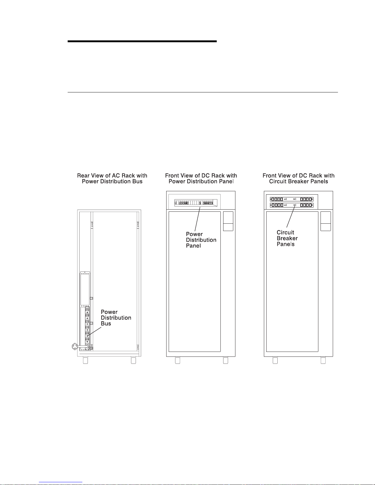
Power Distribution Systems
This section describes power components and how power is distributed in the Model
S00 rack.
Power may be distributed to the devices and drawers in a Model S00 rack by a
power distribution bus (PDB), a power distribution panel (PDP), or up to two circuit
breaker panels.
Chapter 1. Reference Information 1-1
Page 14

Power Distribution Bus
A Model S00 rack may contain one or two power distribution busses (PDBs). A PDB
contains eight unswitched 200 V to 240 V AC outlets for providing power to all the
devices and drawers in the rack. Each outlet is connected to a separate circuit
breaker for protection against excessive currents.
1-2 7014 Model S00 Rack Installation and Service Guide
Page 15
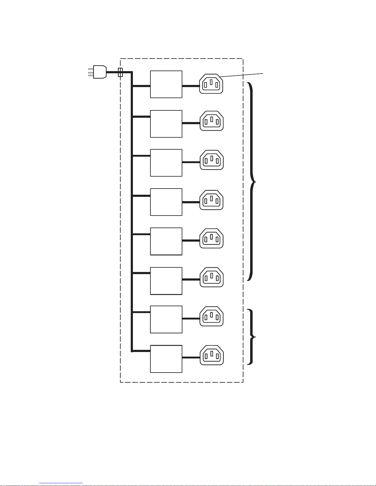
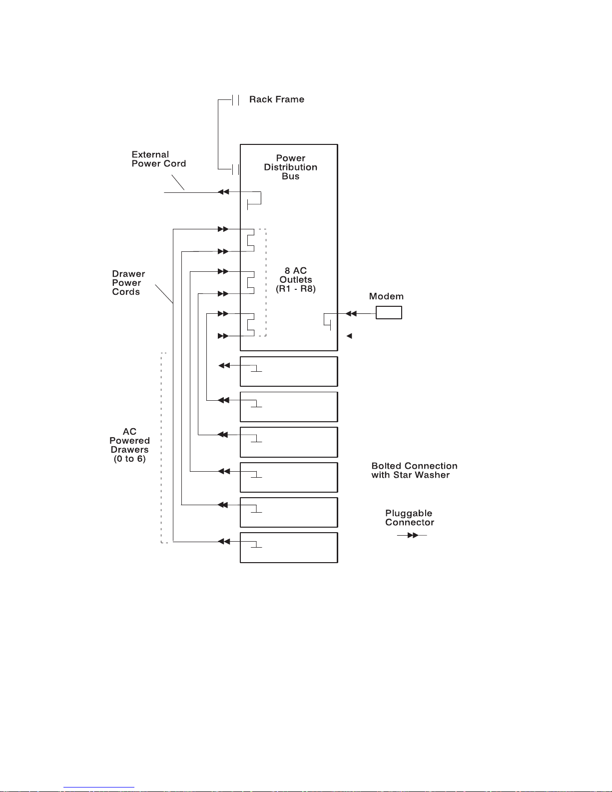
Power Distribution with the Power Distribution Bus
AC
Power
Plug
1
2
3
Reset
Circuit
Breaker
Reset
Circuit
Breaker
Reset
Circuit
Breaker
Reset
Circuit
Breaker
Reset
Circuit
Breaker
Reset
Circuit
Breaker
4
5
6
AC
Outlet (8)
Reset
Circuit
Breaker
Reset
Circuit
Breaker
7
8
For
Drawers
Spare Connectors
Chapter 1. Reference Information 1-3
Page 16
Grounding Diagram - Power Distribution Bus
*
*
*
***
*
*
*
*
*
*
*
*
*
*
*
*
*
*
*
***
***
***
***
***
***
*
*
*
1-4 7014 Model S00 Rack Installation and Service Guide
Page 17
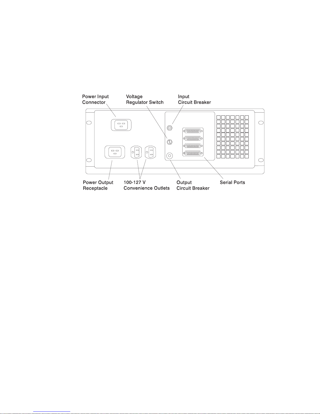
Uninterruptible Power Source
An uninterruptible power source (UPS) may be installed in a Model S00 rack
containing a power distribution bus. The UPS contains one power plug (in) and one
power outlet (out) for connecting to the PDB.
Uninterruptible Power Source, Rear View
Chapter 1. Reference Information 1-5
Page 18

Power Distribution Panel
A power distribution panel (PDP) may be installed in a Model S00 rack to distribute
-48 V DC power to the drawers and devices in the rack. The power distribution
panel provides circuit breakers that protect each drawer in the rack from excess
current and function as DC power switches for switching off power to the devices
and drawers before servicing.
Note: The power distribution panel configurations shown in this manual are for
example purposes only. The actual power distribution panel installed in the
rack you are servicing may vary in terms of circuit breaker ratings, circuit
breaker configurations, and connections to the customer's power source.
The PDP contains a connection location on the rear cover for attaching a customer
supplied circuit breaker alarm. This alarm indicates when any circuit breaker is
switched to the off position.
The circuit breaker switch is on when it is in the up position, and the switch is off
when it is in the down position.
1-6 7014 Model S00 Rack Installation and Service Guide
Page 19
Power Distribution Panel (Front View)
Chapter 1. Reference Information 1-7
Page 20
Power Distribution Panel (Rear View)
1-8 7014 Model S00 Rack Installation and Service Guide
Page 21

Power Distribution with the Power Distribution Panel
Note: The -48 V DC Model S00 rack must be connected to a -48 V DC supply
source which is electrically isolated from its AC power source. The -48 V DC
power source must also be reliably grounded.
Note: The -48 V DC Model S00 rack may be connected to more than one power
source.
The circuit breakers in a power distribution panel are mounted on two power bus
bars. The bus bars may be connected either to a common or to separate customer
-48 V DC power sources.
Typically, a PDP connected to two customer power sources will contain two matching
banks of circuit breakers. Each bank of circuit breakers is connected to a separate
power source. The -48 V DC power supply in each drawer in the rack is then
connected to one circuit breaker in each bank of the PDP. Thus, if one of the
customer power sources were to fail, the devices in the rack would still receive power
from the other source.
If a PDP is connected to only one customer power source, then the drawers in the
rack will be connected to only one circuit breaker each.
The exact configuration of power distribution in a Model S00 rack with a power
distribution panel depends on the particular configuration of drawers installed in the
rack. The diagrams on the following pages illustrate several general examples of
power distribution for a standalone Model S00 rack containing a CPU enclosure.
When servicing the power distribution system in a -48 V DC Model S00 rack, take
care to determine the exact configuration being used prior to servicing.
Chapter 1. Reference Information 1-9
Page 22
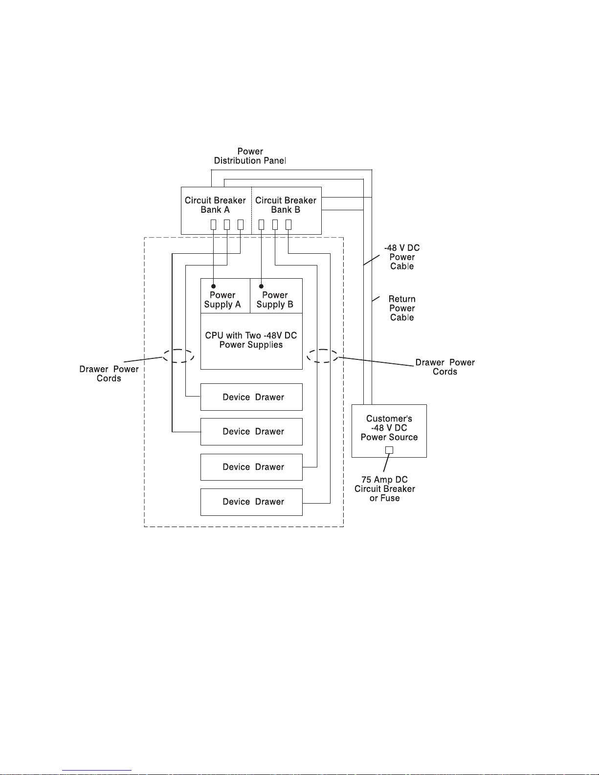
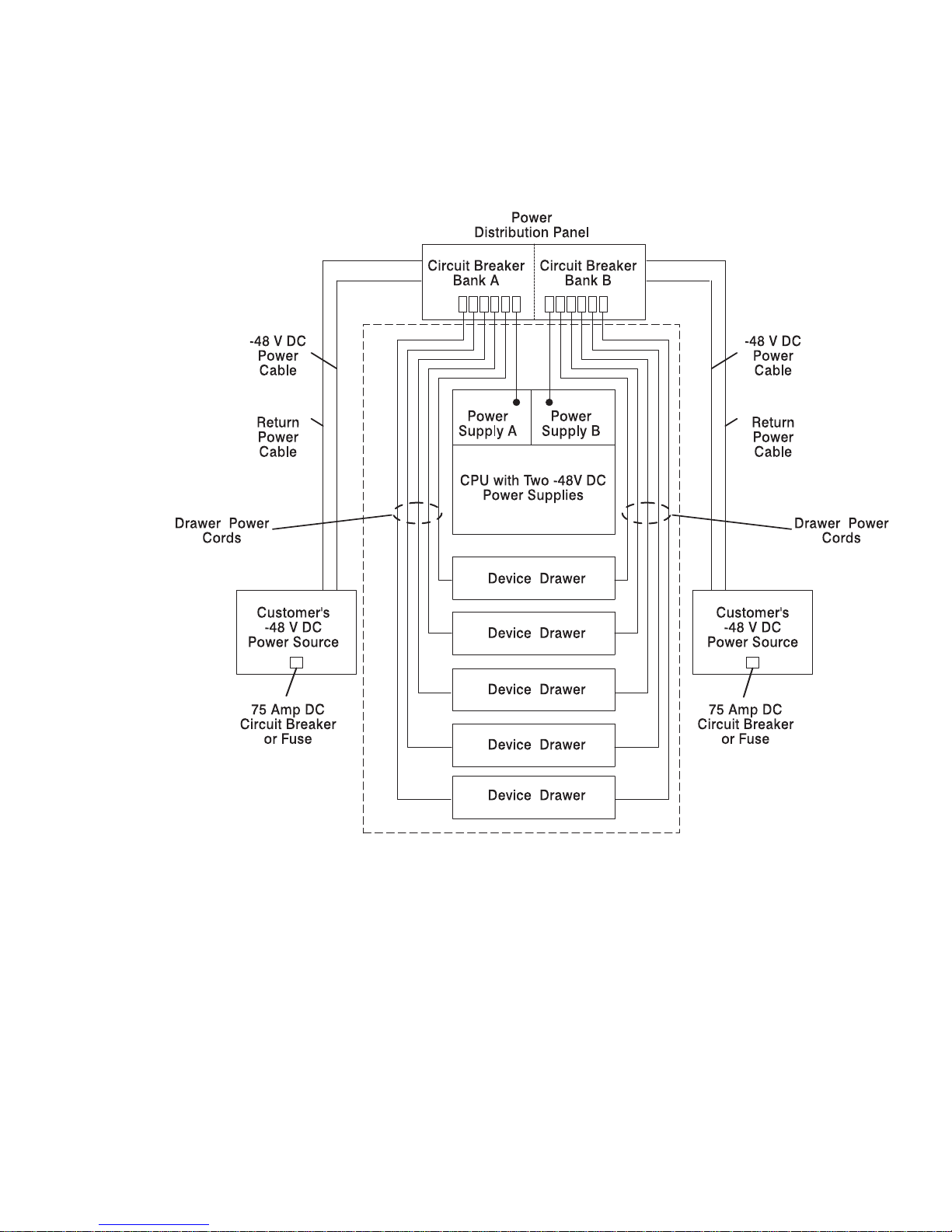
The following diagram shows power distribution in a typical Model S00 rack
configuration connected to one customer supplied power source. Note how each
power supply on the CPU enclosure is connected to a separate circuit breaker. Note
also how both banks of circuit breakers in the PDP are connected to the same power
source.
1-10 7014 Model S00 Rack Installation and Service Guide
Page 23
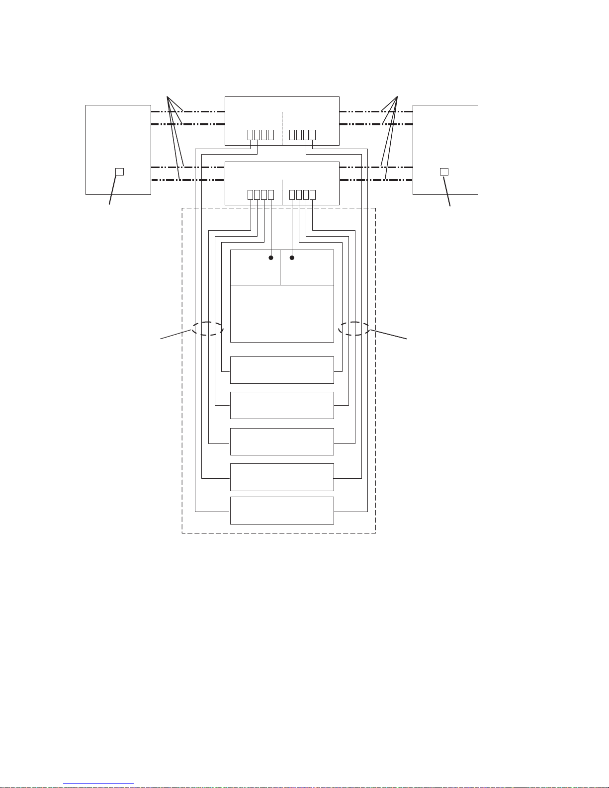
The following diagram shows power distribution in a typical Model S00 rack
configuration connected to two customer supplied power sources. Note also how
each bank of circuit breakers in the PDP is connected to a different power source.
Note how each drawer in the rack is powered by each power source.
Chapter 1. Reference Information 1-11
Page 24
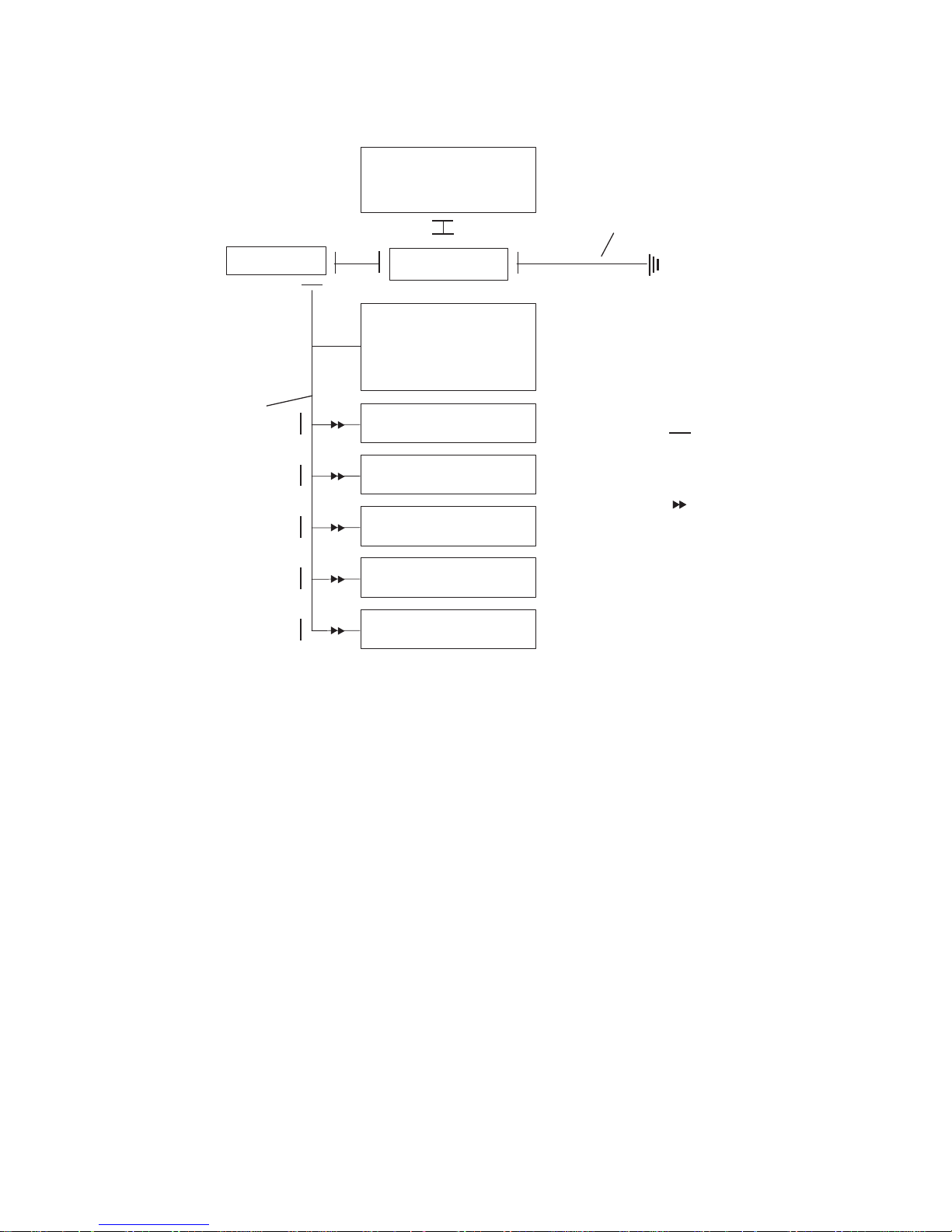
Grounding Diagram - Power Distribution Panel (-48 V DC)
Power
Distribution
Panel
Rack Frame
Ground Bus Bar
Customer's External
Ground Cable
Rack Ground Cable
Pluggable
Connector
CPU with One or Two
-48 V DC Power Supplies
Device Drawer
***
Device Drawer
***
Device Drawer
***
Device Drawer
***
Device Drawer
***
Bolted Connection
with Star Washer
***
***
***
***
***
***
***
1-12 7014 Model S00 Rack Installation and Service Guide
Page 25

Circuit Breaker Panel
Up to two circuit breaker panels may be installed in a Model S00 rack to distribute
-48 V DC power. Each circuit breaker panel provides 8 circuit breakers that protect
each drawer in the rack from excess current and function as DC power switches for
switching off power to the devices and drawers within a rack before servicing. Like
the power distribution panel, each circuit breaker panel may be connected to one or
two customer power sources.
Two standard circuit breaker panels are available with the Model S00 rack. One
circuit breaker panel contains 8 - 15A circuit breakers. The other circuit breaker
panel contains four 20A and four 10A circuit breakers.
The circuit breaker switch is on when it is in the up position, and the switch is off
when it is in the down position.
Chapter 1. Reference Information 1-13
Page 26
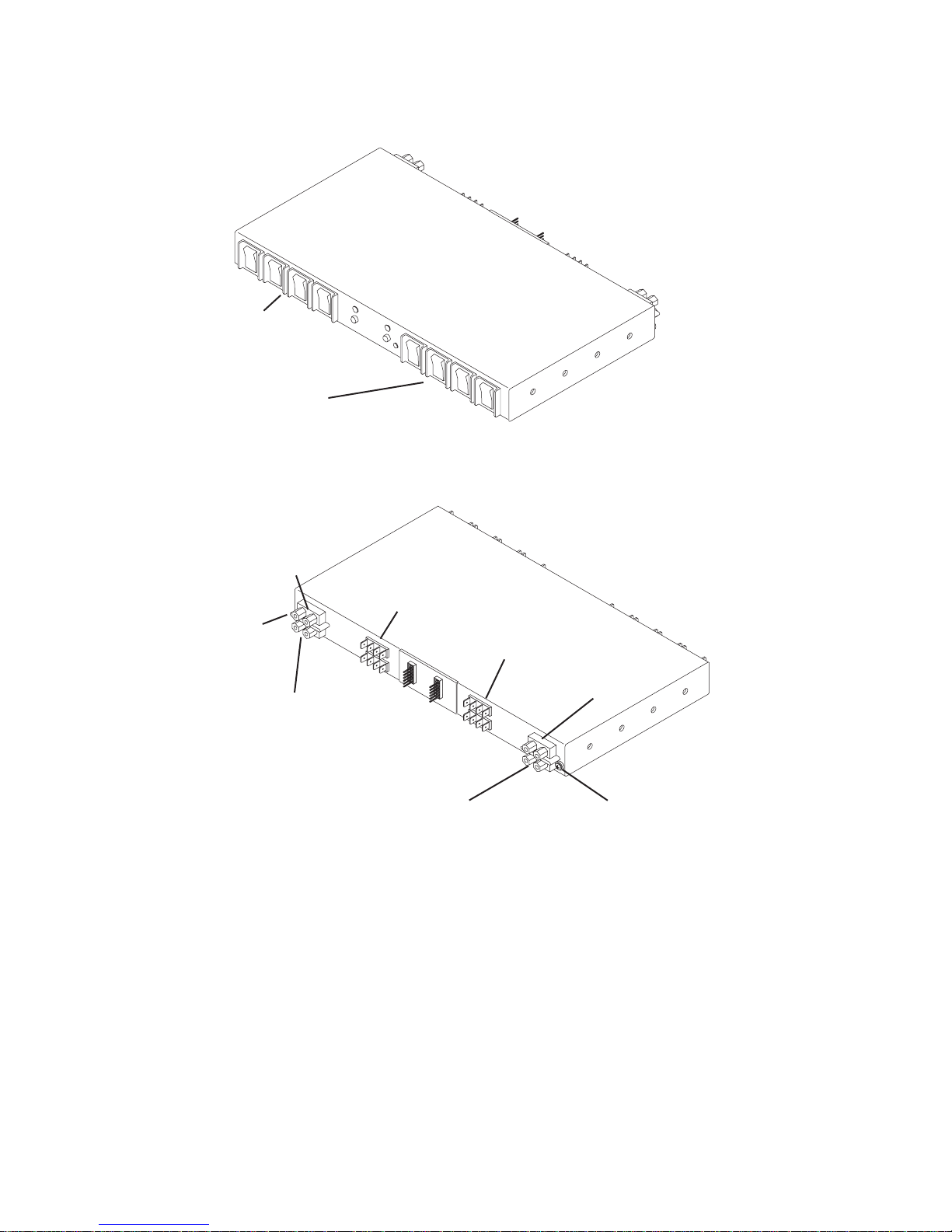
Circuit Breaker Panel (Front View)
Circuit Breaker
Switches
(Bank A)
Circuit Breaker
Switches
(Bank B)
A
A
BB
Circuit Breaker Panel (Rear View)
Device
Connections
(Bank B)
Device
Connections
(Bank A)
-48 V DC Input
(Bank B)
-48 V DC Input
(Bank A)
Positive Ground
(Bank B)
Positive Ground
(Bank A)
Ground Cable
Connector
Ground Cable
Connector
(not pictured)
1-14 7014 Model S00 Rack Installation and Service Guide
Page 27

Power Distribution with the Circuit Breaker Panel
Note: The -48 V DC Model S00 rack must be connected to a -48 V DC supply
source which is electrically isolated from its AC power source. The -48 V DC
power source must also be reliably grounded.
In general, the power distribution and grounding strategies for a -48 V DC Model S00
rack equipped with a circuit breaker panel is similar to a rack equipped with a power
distribution panel. Basically, the circuit breaker panels accept power from up to two
customer power sources and distribute parallel power feeds to each device in the
rack. Device power cables from a 15A circuit breaker panel are typically connected
first to the terminal strips in the circuit breaker panel chassis, and then from the
terminal strips to the devices.
The exact configuration of power distribution in a Model S00 rack with a circuit
breaker panel depends on the particular configuration of drawers installed in the
rack. The diagram below shows a general example of power distribution for a
standalone Model S00 rack containing a CPU enclosure. When servicing the power
distribution system in a -48 V DC Model S00 rack, take care to determine the exact
configuration being used prior to servicing. Refer to the service guide for the system
or devices in your rack for more information.
Chapter 1. Reference Information 1-15
Page 28
Drawer Power
Cables
Drawer Power
Cables
Customer's
-48 V DC
Power Source
Customer's
-48 V DC
Power Source
Customer's -48 V DC
and Return Ground
Power Cables
Customer's -48 V DC
and Return Ground
Power Cables
Device Drawer
with Two -48V DC
Power Supplies
Device Drawer
Device Drawer
Device Drawer
Device Drawer
Device Drawer
Power
Supply A
Circuit Breaker Panel
Circuit Breaker Panel
Bank B
Bank B
Bank A
Bank A
Power
Supply B
75 Amp DC
Circuit Breaker
or Fuse
75 Amp DC
Circuit Breaker
or Fuse
1-16 7014 Model S00 Rack Installation and Service Guide
Page 29
Grounding Diagram - Circuit Breaker Panel (-48 V DC)
Circuit Breaker Panel
Circuit Breaker Panel
Rack Frame
Ground Bus Bar
Terminal Strip
Customer's External
Ground Cable
Rack Ground Cable
Pluggable
Connector
Device Drawer
***
Device Drawer
***
Device Drawer
***
Device Drawer
***
Device Drawer
***
Bolted Connection
with Star Washer
***
***
***
***
***
***
***
***
***
***
***
Chapter 1. Reference Information 1-17
Page 30

Mounting Rails
The rails and mounting hardware for CPU enclosures and non-CPU enclosures are
different. Refer to “ Detail 3. Rails and Front Bezels” on page 6-6 in Chapter 6,
Parts Information (AC Rack) for details of the required mounting hardware.
1-18 7014 Model S00 Rack Installation and Service Guide
Page 31

Specifications
Dimensions
Height: 1577 mm (62.0 inches)
Depth: 1019 mm (40.1 inches)
Depth (without doors): 887 mm (34.9 inches)
Width: 650 mm (25.5 inches)
Weight
Empty Rack: 158 kg (349 pounds)
Standard Configuration: 205 kg (450 pounds)
Maximum Configuration: 455 kg (1000 pounds)
Power
-48 V DC Model S00
Standard Configuration: 1.5 kVA
Maximum Configuration: 2.0 kVA
AC Model S00
Standard Configuration: 0.6 kVA
Maximum Configuration: 2.2 kVA
System Limit: 4.8 kVA
Operating Voltage: 200 to 240 V AC
Frequency: 50 or 60 Hz
Temperature Requirements
Operating: 10 to 405C (50 to 1045F)
Nonoperating: 10 to 525C (50 to 1265F)
Relative Humidity Requirements (Noncondensing)
8 to 80%
Chapter 1. Reference Information 1-19
Page 32

External AC Power Cables
To avoid electrical shock, the manufacturer provides a power cable with a grounded
attachment plug. Use only properly grounded outlets.
Power cables used in the United States and Canada are listed by Underwriter's
Laboratories (UL) and certified by the Canadian Standards Association (CSA).
These power cords consist of the following:
Electrical cables, type ST
Attachment plugs complying with National Electrical Manufacturers Association
(NEMA) L6-30P
Appliance couplers complying with International Electrotechnical Commission
(IEC) Standard 320, Sheets C13 and C14.
Power cables used in other countries consist of the following:
Electrical cables, type HD21 or HD22
Attachment plugs approved by the appropriate testing organization for the
specific countries where they are used
Appliance couplers complying with International Electrotechnical Commission
(IEC) Standard 320, Sheet C13 and C14.
Refer to “Detail 11. Power Cords” on page 6-22 of Chapter 6, Parts Information (AC
Rack) to find the power cables that are available for the AC Model S00 rack.
-48 V DC Power Cables
e customer is responsible for providing power cables from the customer's power
source to the power distribution panel (PDP). The -48 V DC Model S00 rack must
be connected to a -48 V DC power source which is electrically isolated from its AC
power source. In addition, the -48 V DC source is to be reliably grounded.
Note: The -48 V DC Model S00 rack may be connected to two separate -48 V DC
power sources. Both power sources must be properly isolated and grounded.
Power cables used in the United States and Canada are listed by Underwriter's
Laboratories (UL) and certified by the Canadian Standards Association (CSA).
These power cables have the following characteristics:
Power cables and ground cables must be a minimum of 6 AWG stranded copper
(or equivalent) for lengths up to 50 feet from the power source.
All connectors must be the copper crimp type (compression). Connector metal
must be compatible with the cable metal.
1-20 7014 Model S00 Rack Installation and Service Guide
Page 33

Chapter 2. System Installation
This chapter contains information about installing and preparing a Model S00 rack for
system operations.
Observe These Safety Notices During Installation
Note: For a translation of this safety notice, see the
System Unit Safety Information
manual.
DANGER
An electrical outlet that is not correctly wired could place hazardous
voltage on metal parts of the system or the devices that attach to the
system. It is the responsibility of the customer to ensure that the outlet
is correctly wired and grounded to prevent an electrical shock.
Before installing or removing signal cables, ensure that the power
cables for the system unit and all attached devices are unplugged.
When adding or removing any additional devices to or from the system,
ensure that the power cables for those devices are unplugged before
the signal cables are connected. If possible, disconnect all power
cables from the existing system before you add a device.
Use one hand, when possible, to connect or disconnect signal cables
to prevent a possible shock from touching two surfaces with different
electrical potentials.
During an electrical storm, do not connect cables for display stations,
printers, telephones, or station protectors for communication lines.
CAUTION:
This product is equipped with a 3-wire power cable and plug for the user's
safety. Use this power cable in conjunction with a properly grounded electrical
outlet to avoid electrical shock.
CAUTION:
This unit may have more than one power supply cord. To completely remove
power, you must disconnect all power supply cords.
Chapter 2. System Installation 2-1
Page 34

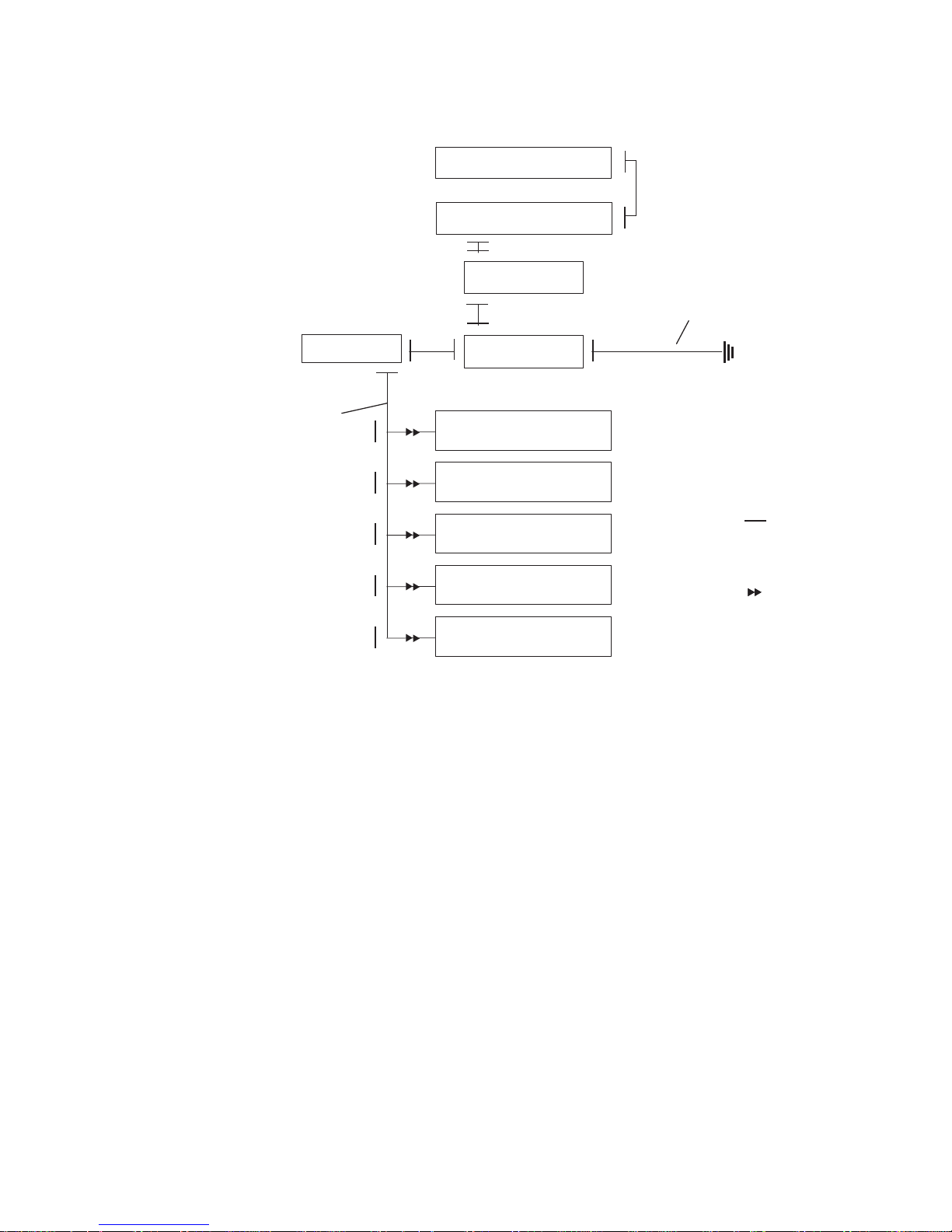
Installation Overview
Step 7:
Connect the Drawer
and Device Cables
Start
Step 3:
Attach the Stabilizer
and Door Guide
Step 4B:
Attach the Rack
through a Raised Floor
Step 4A:
Attach the Rack
to a Concrete Floor
Step 2:
Level the Rack
Step 1:
Position the Rack
Step 6.1:
Connect the
Power
Distribution Panel
Step 6.4:
Connect the Power
Distribution Bus
Step 6.2:
Connect the
Circuit Breaker
Panels
Step 5 (Optional):
Attach the Convenience
Outlet Mounting Plates
Will the rack be
bolted down to
the floor?
Will the rack
be bolted down
through a raised
floor?
Will the rack
accept low
voltage (-48 V
DC) power?
Does the rack
have a Power
Distribution
Panel?
Step 6.3:
Check the
Customer's AC
Outlets
End
No
No
No
No
Yes
Yes
Yes
Yes
Step 8:
Power-on and
Checkout
2-2 7014 Model S00 Rack Installation and Service Guide
Page 35

Step 1. Position the Rack
Note: It is the customer's responsibility to unpack the system unit and place it
where it is to be installed. If this has not been done, consult the customer
and the marketing representative as necessary.
Note: The -48 V DC Model S00 rack must be installed only in restricted access
areas such as dedicated equipment rooms or equipment closets in
accordance with Articles 110-16, 110-17, and 110-18 of the National
Electrical Code, ANSI/NFPA No. 70.
1. If the customer has not unpacked the system unit, remove all packing and tape
from the rack.
2. Position the rack according to the customer floor plan. If the rack has a front
door installed, the rack should have a minimum of 3 to 5 inches of clearance on
both the left and right sides of the rack for access to the front door handle.
3. Lock each caster wheel by tightening the thumbscrew on the caster.
Thumbscrew
Step 2. Level the Rack
Adjust the leveling feet by doing the following:
1. Loosen the locking nut by turning the locking nut counter-clockwise (away from
the bottom of the rack).
2. Adjust the height of the leveling feet by rotating the leveling feet either upward or
downward according to the level of the surface on which the rack is placed.
Repeat this for the remaining leveling feet as needed.
Chapter 2. System Installation 2-3
Page 36

3. When the rack is level, tighten the locking nuts on all of the leveling feet.
Leveling Feet (4)
Locking Nut
Step 3. Attach the Stabilizer and Door Guide
Note: If the rack will be bolted down to a concrete floor, skip to “Step 4. Bolt Down
the Rack” on page 2-8.
Note: For a translation of this safety notice, see the
System Unit Safety Information
manual.
CAUTION:
The stabilizer must be firmly attached to the bottom front of the rack to prevent
the rack from turning over when the drawers are pulled out of the rack. Do not
pull out or install any drawer or feature if the stabilizer is not attached to the
rack.
1. Align the slots in the stabilizer with the mounting holes in the bottom front of the
rack.
2. Ensure that the base of the stabilizer rests firmly on the floor.
2-4 7014 Model S00 Rack Installation and Service Guide
Page 37

3. Install the two mounting screws and hand tighten.
Mounting Hole
Mounting Screw
Stabilizer
4. Use the crank supplied with the system unit to alternately tighten the mounting
screws until they are firmly seated.
Mounting Screw
Chapter 2. System Installation 2-5
Page 38

5. Hang the crank and tightening rod on the bracket near the bottom of the right
wall inside the back of the rack.
Crank
Tightening
Rod
2-6 7014 Model S00 Rack Installation and Service Guide
Page 39

6. If the rack has a front door, use a 3 millimeter allen wrench to install the door
guide to the mounting bracket as shown below with the screw provided.
7. Skip to “Step 6.4. Connect the Power Distribution Bus” on page 2-34.
Chapter 2. System Installation 2-7
Page 40

Step 4. Bolt Down the Rack
What do I do next?
The Model S00 rack is available with optional bolt-down hardware to secure the
rack to a concrete floor, or to a concrete floor through a raised floor.
If the rack will be mounted to a concrete floor, perform “Step 4.1. Attaching the
Rack to a Concrete Floor (Optional).”
If the rack will be mounted to a concrete floor beneath a raised floor, perform
“Step 4.2. Attaching the Rack to a Concrete Floor Beneath a Raised Floor
(Optional)” on page 2-12.
If the rack will not be bolted down, be sure you have attached the stabilizer and
skip to “Step 6.4. Connect the Power Distribution Bus” on page 2-34.
Note: The customer is responsible for attaching the rack mounting plates to the
concrete floor.
Step 4.1. Attaching the Rack to a Concrete Floor (Optional)
Note: Because of the long length of the four rack-mounting bolts, the drawer
located in the bottom position of the rack must be removed to install the four
rack-mounting bolts to the floor.
1. If a drawer is installed in the bottom position in the rack, remove the drawer. For
information about removing the drawer from the rack, refer to the installation or
service guide for the appropriate drawer.
2. Mark the floor around the edge of each leveling foot.
3. Place the two mounting plates in the approximate mounting locations under the
rack.
4. To align the rack over the mounting plates, do the following:
a. Place the four rack-mounting bolts through the mounting holes at the bottom
of the rack.
b. Position the mounting plates under the four rack-mounting bolts so that the
mounting bolts are centered directly over the tapped holes.
c. Insert the rack-mounting bolts 3 to 4 rotations into the tapped holes.
5. Mark the floor around the edge of both mounting plates.
6. Remove the mounting bolts from the threaded holes.
2-8 7014 Model S00 Rack Installation and Service Guide
Page 41

7. To access the holes in the mounting plates, raise the four leveling feet, and then
move the rack away from the mounting plates.
8. Mark the floor at the center of each hole in the mounting plate (including the
tapped holes).
9. Remove the two mounting plates from the marked locations.
10. At the marked location of the tapped mounting holes, drill two holes
approximately 1 inch deep to allow clearance for the ends of the two
rack-mounting bolts The ends of the rack-mounting bolts may protrude past the
thickness of the mounting plate.
Note: A minimum of three anchor bolts for each mounting plate must be used
to mount the plates to the concrete floor. Because some of the drilled
holes may be aligned with concrete reinforcement rods below the surface
of the concrete floor, some of the drilled holes may not be usable. For
each mounting plate, select at least three usable holes, two that are on
opposite sides and opposite ends of each other, and one hole at the
center.
Mounting Plate (2)
Location Marks
(Drill One of
TheseTwo Marks)
Holes for Anchor
Bolts (10)
Tapped Holes for
Rack Mounting Bolts
Mounting Holes
Mounting Holes
Rack Mounting Bolts
Front of
Rack
Location Marks (Drill One
of These Two Marks)
Location Marks (Drill
One of These Six Marks)
11. Drill one hole in each group of anchor bolt location marks as indicated on the
marked floor.
Chapter 2. System Installation 2-9
Page 42

12. Using at least three anchor bolts for each mounting plate, mount the two
mounting plates to the concrete floor.
13. Using the location marks for the leveling feet as a guide, reposition the rack over
the mounting plates.
14. Place the four rack-mounting bolts through the four metal washers, and then
through the four plastic isolator washers. The flat side of the plastic isolator
washer must be facing upward.
15. To further align the rack over the mounting plates do the following:
a. Place the four rack-mounting bolts (with the four plastic isolator washers)
through the mounting holes in the bottom of the rack.
b. Align the four mounting bolts to the location of the four tapped holes in the
two mounting plates.
c. Insert the rack-mounting bolts 3 to 4 rotations into the tapped holes.
Note: The bottom of the four leveling feet must be positioned over the four
plastic isolator pads when the rack is leveled.
If you are installing an AC rack, do not use the four plastic isolator
pads.
16. Place the four plastic isolator pads under the four leveling feet, and then level the
rack using the four adjustable leveling feet.
17. Tighten the locking nuts on the leveling feet.
2-10 7014 Model S00 Rack Installation and Service Guide
Page 43

Mounting
Plates (2)
Location
Marks
Holes for
Anchor Bolts
Tapped Holes for
Rack Mounting Bolts
Mounting
Holes
Front of
Rack
Plastic Isolator
Washer (4)
Leveling Foot (4)
Plastic Isolator
Pad (4)
Rack-Mounting
Bolts
Rack-Mounting
Bolts
18. Tighten the four rack-mounting bolts into the two mounting plates.
19. Skip to “Step 5. Attach the Convenience Outlet Mounting Plates (Optional)” on
page 2-16.
Chapter 2. System Installation 2-11
Page 44

Step 4.2. Attaching the Rack to a Concrete Floor Beneath a Raised
Floor (Optional)
Note: Because of the long length of the four rack-mounting bolts, the drawer
located in the bottom position of the rack must be removed to install the four
rack-mounting bolts to the raised floor.
1. If a drawer is located in the bottom position of the rack, remove it now. For
information about removing the drawer from the rack, refer to the the installation
or service guide for the appropriate drawer.
2. Mark the floor locations around the edge of each leveling foot.
3. Place the two mounting plates in the approximate mounting locations under the
rack.
4. To align the rack over the mounting plates, do the following:
a. Place the four rack-mounting bolts in the mounting positions at the bottom of
the rack.
b. Align the tapped holes of the mounting plates with the location of the four
rack-mounting bolts.
c. Insert the rack-mounting bolts 3 to 4 rotations into the tapped holes.
5. Mark the raised-floor panel around the edge of both mounting plates.
6. Remove the mounting bolts from the threaded holes.
7. To access the holes in the mounting plates, raise the four leveling feet, and then
move the rack away from the mounting plates.
8. Mark the raised-floor panel at the center of each hole in the mounting plates
(including the tapped holes).
9. Remove the two mounting plates from the marked locations.
2-12 7014 Model S00 Rack Installation and Service Guide
Page 45

Mounting Plate (2)
Holes for Anchor
Bolts (10)
Tapped Holes for
Rack Mounting Bolts
Mounting Holes
Mounting Holes
Rack Mounting Bolts
Front of
Rack
Projection of Mounting
Plates onto Concrete Floor
Raised
Floor Panels
10. At the marked location of the tapped mounting holes, drill two holes
approximately 1 inch deep to allow clearance for the ends of the two
rack-mounting bolts The ends of the rack-mounting bolts may protrude past the
thickness of the mounting plate.
Note: A minimum of three anchor bolts for each mounting plate must be used
to mount the plates to the raised floor panel. For each mounting plate,
select at least three usable holes, two that are on opposite sides and
opposite ends of each other and one at the center.
11. Drill one hole in each group of anchor bolt location marks as indicated on the
marked raised floor panel.
12. Ensure that the marks for the holes for the anchor bolts in the concrete floor
align with the holes in the raised floor panel.
13. Drill the holes in the concrete floor for the anchor bolts.
Chapter 2. System Installation 2-13
Page 46
Mounting Plate (2)
Holes for Anchor
Bolts (10)
Tapped Holes for
Rack Mounting Bolts
Mounting Holes
Mounting Holes
Rack Mounting Bolts
Front of
Rack
Projection of Mounting
Plates onto Concrete Floor
Raised
Floor Panels
Location Marks
(Drill One of
These Six Marks)
Location Marks
(Drill One of
These Two Marks)
Location Marks
(Drill One of
These Two Marks)
14. Place the two mounting plates on the locations indicated on the marked
raised-floor panel.
15. Using at least three anchor bolts for each mounting plate, mount the two
mounting plates through the raised-floor panel to the concrete floor.
16. Using the location marks for the leveling feet as a guide, reposition the rack over
the mounting plates.
17. Place the four rack-mounting bolts through the four metal washers and then
through the four plastic isolator washers. The flat side of the plastic isolator
washer must be facing upward.
18. To align the rack over the mounting plates, do the following:
a. Place the four rack-mounting bolts in the mounting positions at the bottom of
the rack.
2-14 7014 Model S00 Rack Installation and Service Guide
Page 47

b. Align the tapped holes of the mounting plates with the location of the four
rack-mounting bolts.
c. Insert the rack-mounting bolts 3 to 4 rotations into the tapped holes.
Note: The bottom of the four leveling feet must be positioned over the four
plastic isolator pads when the rack is leveled.
If you are installing an AC rack, do not use the four plastic isolator
pads.
19. Place the four isolator pads under the four leveling feet, and then level the rack
using the four adjustable leveling feet.
20. Tighten the four rack-mounting bolts into the two mounting plates.
Mounting
Plates (2)
Location
Marks
Holes for
Anchor Bolts
Tapped Holes for
Rack Mounting Bolts
Mounting
Holes
Front of
Rack
Plastic Isolator
Washer (4)
Leveling Foot (4)
Plastic Isolator
Pad (4)
Rack-Mounting
Bolts
Rack-Mounting
Bolts
21. Tighten the locking nuts on the leveling feet.
Chapter 2. System Installation 2-15
Page 48

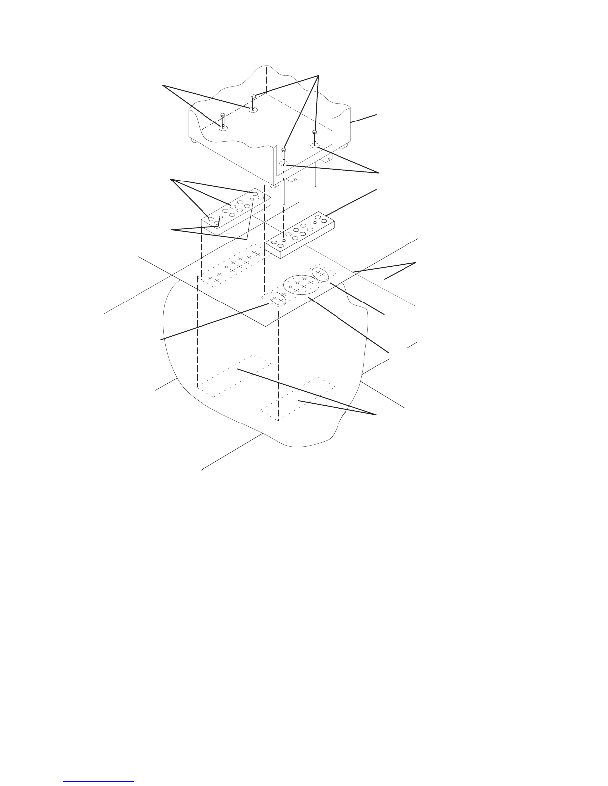
Step 5. Attach the Convenience Outlet Mounting Plates (Optional)
An optional feature of the -48 V DC Model S00 rack are mounting plates for
customer installed convenience AC electrical outlets. These mounting plates may be
installed at the base of the front and rear of the rack. In addition to providing a
mounting location for an electrical outlet, each plate has a lug and ground cable for
grounding the customer's test equipment.
Note: The customer is responsible for providing both the front electrical outlet
assembly and the power cable from the customer power source to the front
electrical outlet. The customer is also responsible for having the electrical
outlet assembly properly connected by a professional electrician. These
items are not field replaceable units.
1. If the customer does not want to connect an electrical outlet to the mounting
plate at this time, but wants the mounting plate installed, skip to step 4 on
page 2-17.
2. Remove the blank filler plate in the outlet opening on the mounting plate.
2-16 7014 Model S00 Rack Installation and Service Guide
Page 49

3. After the customer has connected the power cable from the customer power
source to the electrical outlet assembly, mount the electrical outlet assembly to
the mounting plate using the two mounting screws (provided by the customer).
Front of Rack
Mounting Plate
Electrical Outlet
Assembly
Power Cable From
Power Source
Mounting Screws
4. Place the ground cable lug through the mounting hole of the mounting plate.
Chapter 2. System Installation 2-17
Page 50

5. Locate the Y-shaped grounding cable supplied with the mounting plates.
Connect the long end of the ground cable to the threaded side of the ground
cable lug (inside the mounting plate), and then install and tighten the ground lug
nut. Feed the ground cable underneath the rack.
Note: The two remaining connectors of the ground cable are done in step 17 on
page 2-24.
Mounting
Plate
Front of Rack
Ground Lug
Long End of
Ground Cable
Mounting
Hole
Long End of Ground
Cable
Y-End of
Ground Cable
Ground Connector
(Short End of
Ground Cable)
Ground Lug Nut
2-18 7014 Model S00 Rack Installation and Service Guide
Page 51

6. Find the crank (for installing the mounting screws) located inside the rear of the
rack near the bottom of the right wall.
Crank
7. Align the holes of the mounting plate with the holes on the rack, and then install
the two mounting screws.
Chapter 2. System Installation 2-19
Page 52

8. Using the crank, tighten the two mounting screws.
Mounting
Screws
Crank
Mounting
Plate
Front of Rack
9. Store the crank inside the rear of the rack near the bottom of the right wall.
10. Open the rear door of the rack.
11. If the customer does not want to connect an electrical outlet to the mounting
plate at this time, but wants the mounting plate installed, skip to step 14 on
page 2-21.
12. If the customer wishes to install an outlet in the rear electrical mounting plate,
remove the blank filler plate in the outlet opening.
2-20 7014 Model S00 Rack Installation and Service Guide
Page 53

13. After the customer has connected the power cable from the customer power
source to the electrical outlet assembly, mount the electrical outlet assembly to
the mounting plate using the two mounting screws (provided by the customer).
14. Place the ground cable lug through the mounting hole of the mounting plate.
Chapter 2. System Installation 2-21
Page 54

15. Find the ground cable that you fed underneath the rack in step 5 on page 2-18.
Connect the Y-connector of the ground cable to the threaded side of the ground
cable lug, and then install and tighten the ground lug nut. The remaining end of
the ground cable will connect to the ground bus bar in step 17 on page 2-24.
2-22 7014 Model S00 Rack Installation and Service Guide
Page 55

16. Attach the mounting plate to the rack by installing and tightening the three
mounting screws.
Chapter 2. System Installation 2-23
Page 56

17. Connect the remaining connector of the ground cable to the ground bus bar.
18. If you removed any drawers from the bottom of the rack, reinstall them now. For
information about installing drawers into the rack, refer to the installation or
service manual provided with the drawer.
2-24 7014 Model S00 Rack Installation and Service Guide
Page 57

Step 6. Connect the Power Distribution System
What do I do next?
Three power distribution systems are available with the Model S00 rack: a power
distribution panel (-48 V DC), circuit breaker panels (-48 V DC), or a power
distribution bus (AC).
If a power distribution panel is installed on your rack, perform “Step 6.1. Connect
the Power Distribution Panel.”
If a circuit breaker panel is installed on your rack, skip to “Step 6.2. Connect the
Circuit Breaker Panels” on page 2-30.
If a power distribution bus is installed in the rack, skip to “Step 6.4. Connect the
Power Distribution Bus” on page 2-34.
Step 6.1. Connect the Power Distribution Panel
Note: The customer is responsible for providing and connecting the -48 V DC
power cables and the return power cables from the customer's -48 V DC
power sources to the power distribution panel (PDP) of the -48 V DC Model
S00 rack. The customer is also responsible for connecting the
customer-supplied ground cable to the rack frame.
CAUTION:
Energy hazard, remove power before servicing.
1. At the customer's -48 V DC power source, switch off all power for any -48 V DC
power sources that will be connected to the power distribution panel (PDP).
2. After the customer's -48 V DC power sources are switched off, place a tag or
label over the power source switches (or fuses) to indicate that the power
sources are intended to be switched off.
Chapter 2. System Installation 2-25
Page 58
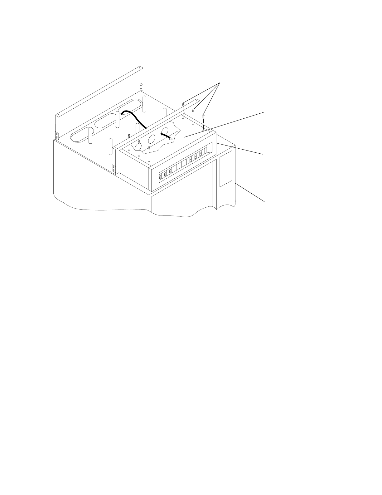
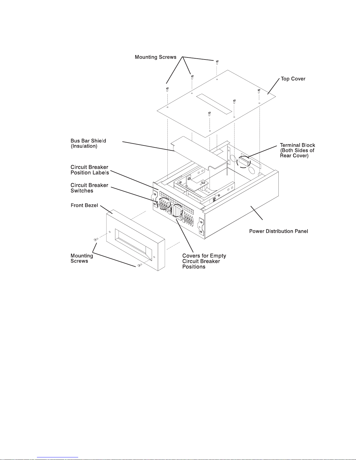
3. Remove the six mounting screws from the top cover of the PDP, and remove the
top cover.
Mounting Screws (6)
Power
Distribution
Panel
Top Cover
Front of
Rack
4. Remove the bus bar shield (insulator) from the PDP.
Attention: The bus bar shield must be properly reinstalled over the return bus
bars to protect against injury when servicing the power distribution panel
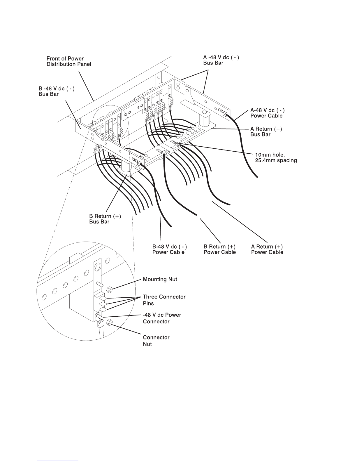
5. Ensure that the customer properly installs the external -48 V DC power cables
to the -48 V DC bus bars and the positive return ground cables to the return bus
bars.
2-26 7014 Model S00 Rack Installation and Service Guide
Page 59

Power
Distribution
Panel
Front of
Rack
-48 V dc Power Cable
and Return Power Cable
-48 V dc Power
Cable and Return
Power Cable
Terminal Board
(On Rear Cover)
Chapter 2. System Installation 2-27
Page 60

6. Replace the bus bar shield (insulator).
7. Replace the top cover of the PDP.
8. If the customer wants to install a power status alarm, tell the customer to connect
the alarm cable to the terminal board located on the rear cover of the power
distribution panel now.
9. Connect the customer's ground cable to the dual ground lugs at the lower rear
corner of the rack.
10. The customer's power cables are normally supplied to the rack from an overhead
source. If the customer's power cables are supplied from the bottom of the rack,
use the cable restraint straps to attach the -48 V DC power cables and return
power cables to the cable restraint mounting brackets.
11. Skip to “Step 7. Connect Drawer and Device Cables” on page 2-35.
2-28 7014 Model S00 Rack Installation and Service Guide
Page 61

Chapter 2. System Installation 2-29
Page 62

Step 6.2. Connect the Circuit Breaker Panels
Note: The customer is responsible for providing and connecting both the -48 V DC
power cables and return power cables from the customer's -48 V DC power
sources to the circuit breaker panels in the -48 V DC Model S00 rack. The
customer is also responsible for connecting the customer-supplied ground
cable to the rack frame.
CAUTION:
Energy hazard, remove power before servicing.
1. At the customer's -48 V DC power sources, switch off all power from any -48 V
DC power sources that will be attached to the circuit breaker panels.
2. After the customer's -48 V DC power sources are switched off, place a tag or
label over the power source switches (or fuses) to indicate that the power
sources are intended to be switched off.
3. Remove the five mounting screws from the top cover of the circuit breaker panel
chassis, and remove the top cover.
2-30 7014 Model S00 Rack Installation and Service Guide
Page 63

4. Ensure that the customer properly connects the external -48 V DC power cables
and return power cables both to the customers -48 V DC power sources and to
appropriate connectors on the circuit breaker panels.
Device
Connections
(Bank B)
Device
Connections
(Bank A)
-48 V DC Input
(Bank B)
-48 V DC Input
(Bank A)
Positive Ground
(Bank B)
Positive Ground
(Bank A)
Ground Cable
Connector
Ground Cable
Connector
(not pictured)
5. Connect the customer's ground cable to the dual ground lugs on the rack.
Chapter 2. System Installation 2-31
Page 64

6. Replace the top cover of the circuit breaker panel chassis, taking care to feed
the customer's power cables and return power cables through the openings at
the rear corners of the top cover.
Typical Circuit Breaker Panel Cabling
20/10A
Rear View of
Circuit Breaker Panels
-48 V dc Power
-48 V dc Power
-48 V dc return
-48 V dc return
Terminal Strips
Typical DASD Drawers
Attach To Circuit
Breaker Panels
Via Terminal Strips
Typical IO Drawers
Attach To Circuit
Breaker Panels
Directly
To Frame Ground
15A
Ground Cables
Step 6.3. Checking Customer AC Outlets
If you are installing an AC rack, perform the following checks on the customer's AC
power source.
If you are installing a -48 V DC, rack, the customer is responsible for checking the
integrity and quality of the -48 V DC power sources. When installing a -48 V DC
Model S00 rack, ensure that the customer has checked his -48 V DC power sources,
then skip to “Step 1. Position the Rack” on page 2-3.
2-32 7014 Model S00 Rack Installation and Service Guide
Page 65

Note: For a translation of this safety notice, see the
System Unit Safety Information
manual.
CAUTION:
Do not touch the receptacle or the receptacle faceplate with anything other
than your test probes before you have met the requirement in step 8.
1. Have the customer locate and turn off the branch circuit circuit breaker for the
customer power outlet. Attach tag S229-0237 to the circuit breaker switch, which
reads "Do Not Operate."
Note: All measurements are made with the receptacle faceplate in the normal
installed position.
2. Some receptacles are enclosed in metal housings. On receptacles of this type,
perform the following steps:
a. Check for less than 1 volt from the receptacle case to any grounded metal
structure in the building, such as a raised-floor metal structure, water pipe,
building steel, or similar structure.
b. Check for less than 1 volt from receptacle ground pin to a grounded point in
the building.
Note: If the receptacle case or faceplate is painted, be sure the probe tip
penetrates the paint and makes good electrical contact with the
metal.
c. Check the resistance from the ground pin of the receptacle to the receptacle
case. Check resistance from the ground pin to the building ground. The
readings should be less than 1.0 ohm, which indicates the presence of a
continuous grounding conductor.
3. If any of the three checks made in substep 2 are not correct, ask the customer to
remove the power from the branch circuit and make the wiring corrections; then
check the receptacle again.
Note: Do not use a digital multimeter to measure grounding resistance.
4. Check for infinite resistance between the ground pin of the receptacle and each
of the phase pins. This is a check for a wiring short to ground or a wiring
reversal.
5. Check for infinite resistance between the phase pins. This is a check for a wiring
short.
Note: For a translation of this safety notice, see the
System Unit Safety
Information
manual.
Chapter 2. System Installation 2-33
Page 66

CAUTION:
If the reading is other than infinity, do not proceed! Have the customer
make necessary wiring corrections before continuing. Do not turn on the
branch circuit circuit breaker until all the above steps are satisfactorily
completed.
6. Have the customer turn on the branch circuit circuit breaker. Measure for
appropriate voltages between phases. If no voltage is present on the receptacle
case or grounded pin, the receptacle is safe to touch.
7. With an appropriate meter, verify that the voltage at the outlet is correct.
8. Verify that the grounding impedance is correct by using the ECOS 1020, 1023,
B7106, C7106, or an appropriately approved ground impedance tester.
Note: Do not use the 120-volt convenience outlets inside a machine to power
the tester.
9. Skip to “Step 6.4. Connect the Power Distribution Bus.”
Step 6.4. Connect the Power Distribution Bus
1. Most systems in Model S00 racks are preconfigured in the factory with all
drawers and devices properly cabled and connected to the power distribution
bus. If this is not the case, plug any unconnected drawer power cables into the
outlets on the rear of the power distribution bus. For information about
connecting drawer and device power cables, see the installation or service guide
for the system or devices installed in your rack.
2. Plug the power distribution bus power cable into the customer's electrical outlet
or power cable.
3. Skip to “Step 7. Connect Drawer and Device Cables” on page 2-35.
2-34 7014 Model S00 Rack Installation and Service Guide
Page 67

Step 7. Connect Drawer and Device Cables
1. If head protectors are installed, remove them from all diskette drives.
2. Most systems in Model S00 racks are preconfigured in the factory, with all
drawer and device cables installed. If you need to install drawer and device
cables:
a. Follow the power control cable installation instructions provided in the
documentation for the appropriate system or device being installed in this
rack.
b. Using the customer planning information, the
Diagnostics Information for
Multiple Bus Systems
, or other information supplied by the customer, connect
the drawer and device cables to the system interface board ports.
c. As needed, use the cable labels included in the ship group to label the
cables. For additional information about labeling the cables, refer to the
Diagnostics Information for Multiple Bus Systems
.
3. Cable restraints are supplied with the rack and can be installed in the rack.
a. Open the cable restraint strap by pressing the release tab and then pulling
the end of the cable restraint strap through the locking mechanism.
b. Place the cables within the cable restraint strap.
c. Close the strap by placing the end of the cable restraint strap through the
locking mechanism, and then pull the end of the cable restraint strap to
tighten the cables against the rack.
Step 8. Power-On and Check Out the System
1. Follow the power-on procedures in Chapter 4, Removal and Replacement for the
power distribution systems installed in your rack.
2. Refer to the
Diagnostics Information for Multiple Bus Systems
and follow the
instructions in the installation checkout procedure.
Chapter 2. System Installation 2-35
Page 68

2-36 7014 Model S00 Rack Installation and Service Guide
Page 69

Chapter 3. Service Inspection Guide
Perform a service inspection on the system when the following conditions occur:
The system is inspected under a maintenance agreement.
Service is requested and service has not recently been performed.
An alterations-and-attachments review is performed.
Changes have been made to the equipment that might affect the safe operation
of the equipment.
External devices with an attached power cord are connected to the system unit.
If the inspection indicates an unacceptable safety condition, the condition must be
corrected before representatives service the machine.
Note: The correction of any unsafe condition is the responsibility of the owner of the
system.
Chapter 3. Service Inspection Guide 3-1
Page 70

Do the following checks:
1. If the rack is bolted down:
a. Ensure that the rack is firmly secured to the floor.
b. Ensure that the four plastic isolator pads are under the four leveling feet.
Mounting
Plates (2)
Location
Marks
Holes for
Anchor Bolts
Tapped Holes for
Rack Mounting Bolts
Mounting
Holes
Front of
Rack
Plastic Isolator
Washer (4)
Leveling Foot (4)
Plastic Isolator
Pad (4)
Rack-Mounting
Bolts
Rack-Mounting
Bolts
3-2 7014 Model S00 Rack Installation and Service Guide
Page 71

2. If the rack is not bolted down, ensure that the stabilizer is firmly attached to the
bottom front of the rack.
Mounting Hole
Mounting Screw
Stabilizer
Note: For a translation of this safety notice, see the
System Unit Safety
Information
manual.
CAUTION:
The stabilizer must be firmly attached to the front of the rack to prevent the
rack from turning over when the drawers are pulled out of the rack. Do not
pull out or install any drawer or feature if the stabilizer is not attached to
the rack.
3. Check the covers for sharp edges and for damages or alterations that expose
the internal parts of the rack.
4. Check the covers for a proper fit to the rack. They should be in place and
secure.
5. Open the back door of the rack.
6. Perform the power-off procedure for the power distribution system installed in
your rack. See Chapter 4, “Removal and Replacement” on page 4-1 for power
off procedures.
7. Check for alterations or attachments. If there are any, check for obvious safety
hazards such as broken wires, sharp edges, or broken insulation.
8. Check the internal cables for damage.
9. Check for dirt, water, and any other contamination within the rack.
10. Check the voltage label on the back of the system unit to ensure that it matches
the voltage at the outlet.
11. Check the external power cable for damage.
Chapter 3. Service Inspection Guide 3-3
Page 72

12. If your rack is a -48 V DC rack, with the customer's ground cable connected to
the system unit, check for 0.1 ohm or less resistance between the metal frame
and the dual ground lugs on the rack.
13. If your rack is an AC rack,
a. With the external power cable connected to the system unit, check for 0.1
ohm or less resistance between the ground lug on the external power cable
plug and the metal frame.
b. Using the appropriate probe, check for 0.1 ohm or less resistance between
the metal frame and the grounding pin on each of the power outlets on the
power distribution bus (R1, R2, R3, ...).
c. Check for the following conditions for each external device that has an
attached power cord:
1) Damage to the power cord.
2) The correct grounded power cord.
3) With the external power cord connected to the device, check for 0.1 ohm
or less resistance between the ground lug on the external power cord
plug and the metal frame of the device.
3-4 7014 Model S00 Rack Installation and Service Guide
Page 73

14. Close the rear cover of the rack.
15. Perform the power-on procedure for the power distribution system installed in
your rack. See Chapter 4, Removal and Replacement for power-on procedures.
Chapter 3. Service Inspection Guide 3-5
Page 74

3-6 7014 Model S00 Rack Installation and Service Guide
Page 75

Chapter 4. Removal and Replacement
This chapter contains information about powering the system on and off, and
removing and replacing components of a Model S00 rack.
Use the correct power-on and power-off procedure for the power distribution systems
in your rack.
Safety Notices
This section contains safety notices that apply to all the procedures in this chapter.
Review this section carefully before performing any power related operations.
Note: For a translation of this safety notice, see the
System Unit Safety Information
manual.
DANGER
An electrical outlet that is not correctly wired could place hazardous
voltage on metal parts of the system or the devices that attach to the
system. It is the responsibility of the customer to ensure that the outlet
is correctly wired and grounded to prevent an electrical shock.
Before installing or removing signal cables, ensure that the power
cables for the system unit and all attached devices are unplugged.
When adding or removing any additional devices to or from the system,
ensure that the power cables for those devices are unplugged before
the signal cables are connected. If possible, disconnect all power
cables from the existing system before you add a device.
Use one hand, when possible, to connect or disconnect signal cables
to prevent a possible shock from touching two surfaces with different
electrical potentials.
During an electrical storm, do not connect cables for display stations,
printers, telephones, or station protectors for communication lines.
CAUTION:
This unit may have more than one power cable. To completely remove power,
you must disconnect all power cables from the unit.
Chapter 4. Removal and Replacement 4-1
Page 76

System Shutdown Warning
Before powering off the drawers or external devices, ask the customer about their
system high availability requirements. Notify the customer if you are going to switch
off power to any attached CPUs or drawers that are contained in this rack or any
attached racks. Notify the customer that other attached systems might be affected
by this procedure.
Before stopping the system unit, you must first shut down the operating system to
prevent losing data.
Attention: Use the appropriate shutdown command before you stop the system unit;
failure to do so may result in the loss of data. See your operating system
documentation for information about the shutdown command.
Power-On Procedure with the Power Distribution Bus
1. Plug all drawer power cables into the outlets on the power distribution bus.
2. Make sure the power cable for the power distribution bus is plugged into the
customer's power cable or outlet.
CAUTION:
This product is equipped with a 3-wire power cable and plug for the user's
safety. Use this power cable in conjunction with a properly grounded electrical
outlet to avoid electrical shock.
Note: If two PDBs are installed in the rack, plug the power cables of both PDBs into
the electrical outlets.
4-2 7014 Model S00 Rack Installation and Service Guide
Page 77

3. Follow the power-on procedure for the system installed in your rack to switch on
power to the system installed in the rack and drawers installed in your rack.
Refer to the service guide for the system installed in your rack for more
information.
4. Close the back door of the rack.
Power-Off Procedure with the Power Distribution Bus
1. Follow the power-off procedure for the system installed in the rack to switch off
both the system and all centrally controlled drawers. Refer to the service guide
for the system installed in your rack for more information.
Note: Because many drawers or devices can be connected to the system unit,
it may be impractical for you to switch off power to all the drawers or
devices and unplug their power cables.
Chapter 4. Removal and Replacement 4-3
Page 78

2. Open the rear door of the rack.
Note: If two power distribution busses (PDB) are installed in your rack and you
are servicing only one of the PDBs, power-off the drawers connected to
the PDB you are servicing, and then connect the power cables for those
drawers to the second PDB. If the second PDB is not being serviced,
you may want to power-on the drawers that you just connected to the
second PDB.
3. Switch off power to all drawers or devices that are connected to the PDB you are
servicing.
4. Unplug the drawer or device power cables from the electrical outlets on the PDB
you are servicing.
5. If drawer or device power cables are not connected to the PDB you are
servicing, unplug the PDB power cable from the customer's power cable or
outlet.
Power-On Procedure with the Power Distribution Panel
CAUTION:
Energy hazard, remove power before servicing. Disconnect two power
supply cords.
Note: It is the customer's responsibility to provide and have a qualified
technician properly install both the -48 V DC power cables and return
power cables from the customer's -48 V DC power sources to the power
distribution panel in the -48 V DC Model S00 rack The customer is also
responsible for connecting the customer-supplied ground cable to the
ground bus bar on the rack frame.
4-4 7014 Model S00 Rack Installation and Service Guide
Page 79

1. Ensure that all circuit breakers are on (circuit breaker switches in the up
position).
Chapter 4. Removal and Replacement 4-5
Page 80

2. Locate terminal board 2 (TB2) located on the outside of the rear panel of the
power distribution panel.
topmar="0.25i".
4-6 7014 Model S00 Rack Installation and Service Guide
Page 81

3. Using a polarity sensitive multimeter, ensure that the customer has properly
connected the power cables (both -48 V DC (-) and return (+)) to the power
distribution panel.
a. Measure for -40 to -60 V DC between positions one and two on terminal
board 2 to test the power for side A.
b. Measure for -40 to -60 V DC between positions five and six on terminal
board 2 to test the power for side B.
4. Plug all external device power cords into the electrical outlets.
5. Switch on power to all external devices attached to the system unit. Refer the
the service guide for the drawers installed in your rack for more information.
6. Switch on power to all of the devices and drawers connected to the PDP. Refer
the the service guide for the drawers installed in your rack for more information.
7. Switch on power to the system installed in the rack. Refer to the service guide
for the CPU enclosure installed in your rack for more information.
Chapter 4. Removal and Replacement 4-7
Page 82

Power-Off Procedure with the Power Distribution Panel
1. Switch off power to the system installed in the rack. Refer to the service guide
for the CPU enclosure installed in your rack for more information.
2. Switch off power to all devices and drawers in the rack. Refer to the service
guide for the drawers installed in your rack for more information.
3. Switch off power to all external devices attached to the system unit. Refer to the
service guide for the drawers installed in your rack for more information.
4. Unplug the device power cords from the electrical outlets.
Note: If drawers in attached racks are connected to circuit breakers in this rack,
power to the drawers in attached racks will be powered-off immediately
when the controlling circuit breakers in this rack are set to off.
5. Except for circuit breakers in this rack that are connected to drawers in other
racks, set all circuit breaker switches to the off position (down).
CAUTION:
Energy hazard, remove power before servicing. Disconnect two power
supply cords.
Note: Because a large number of external devices can be connected to the
system unit, it may be impractical for you to switch off power to all the
devices and unplug their power cords.
4-8 7014 Model S00 Rack Installation and Service Guide
Page 83

Power Distribution Bus
Power Distribution Bus Removal
1. Follow the “Power-Off Procedure with the Power Distribution Bus” on page 4-3.
2. Once you have switched off power and disconnected the power distribution bus
from the customer's power cable, record the locations of the drawer power
cables that are plugged into the power connectors on the power distribution bus.
3. Unplug the drawer power cables from the power distribution bus
4. Remove the four mounting screws from the power distribution bus, and pull the
power distribution bus toward you to access the power connectors on the far side
of the power distribution bus.
Chapter 4. Removal and Replacement 4-9
Page 84

5. Unplug the power cords from the two power connectors on the side of the PDB
facing the front of the rack.
6. Remove the power distribution bus from the rack.
Power Distribution Bus Replacement
1. Reconnect any power cables that you disconnected from the spare power
connectors on the power distribution bus
2. Slide the power distribution bus into the housing.
3. Fasten the power distribution bus to the housing with the four mounting screws.
4. Reconnect any power cables that you disconnected from the power distribution
bus into the correct power connectors.
5. Be sure to set the switches and plug the power cords into the locations that you
recorded during the removal procedure.
6. Do the “Power-On Procedure with the Power Distribution Bus” on page 4-2.
4-10 7014 Model S00 Rack Installation and Service Guide
Page 85

Power Distribution Panel
CAUTION:
Energy hazard, remove power before servicing. Disconnect two power supply
cords.
Power Distribution Panel Removal
1. Do the “Power-Off Procedure with the Power Distribution Panel” on page 4-8.
2. Switch off power at the customer's -48 V DC power sources connected to the
power distribution panel.
Note: Removing power to this power distribution panel does not remove power
to drawers in this rack that are being powered by a power distribution
panel of another rack.
3. Once the customer's -48 V DC power sources are switched off, ensure that a tag
or label is positioned over the switches to indicate that the power sources are
intended to be switched off.
4. Disconnect from the drawers all drawer power cables that are connected to the
PDP.
5. Pull the drawer power cables up through the three holes in the top of the rack.
Chapter 4. Removal and Replacement 4-11
Page 86

6. Remove the six mounting screws from the top cover of the PDP, and then
remove the top cover.
7. Remove the bus bar shield (insulation) from the PDP.
8. With a multimeter, verify that no power exists between the two -48 V DC bus
bars ( - ) and the two return bars (+).
9. Record the locations of the two -48 V DC power cables and the two return power
cables.
4-12 7014 Model S00 Rack Installation and Service Guide
Page 87

10. Ensure that the customer's technician completely disconnects the two -48 V DC
power cables from the two -48 V DC bus bars, and the two positive return
ground cables from the return bus bars. Ensure that the customer's technician
also safely removes the power cables from the rack.
Chapter 4. Removal and Replacement 4-13
Page 88

11. Remove the four mounting screws that attach the PDP chassis to the top of the
rack.
12. Pull the ground bus bar wire out of the back of the power distribution panel.
13. Remove the PDP and all of the attached drawer power cables from the top of the
rack.
Mounting Screws (4)
Power
Distribution
Panel
Front of
Rack
Power Distribution
Panel Chassis
Ground Wire With
Connector
Power Distribution Panel Replacement
1. If it is not already off, remove the top cover of the power distribution panel.
2. Place the power distribution panel on top of the rack, aligning the mounting holes
in the bottom of the chassis with the mounting holes on the top of the rack.
3. Attach the ground bus bar cable to the power distribution panel the mounting
screw as shown in the figure above.
Note: The ground bus bar cable must be attached to an unpainted surface to
ensure proper grounding of the electrical system.
4. Attach the power distribution panel chassis to the top of the rack with the
remaining mounting screws provided (see figure above).
5. Ensure that the customer's power sources that will be connected to this power
distribution panel are switched off.
Note: It is the customer's responsibility to provide and have a qualified
technician install both -48 V DC power cables and return power cables
4-14 7014 Model S00 Rack Installation and Service Guide
Page 89

from the customer's -48 V DC power sources to the power distribution
panel in the -48 V DC Model S00 rack, The customer's technician is also
responsible for connecting the customer-supplied ground cable to the
ground bus-bar on the rack frame.
6. Ensure that the customer's technician properly connects the -48 V DC power
cables to the -48 V DC bus bars and the return power cables to the return bus
bars.
7. Feed the drawer power cables that are attached to the power distribution panel
through the holes in the top of the rack.
8. Replace the bus bar shield (insulation).
9. Replace the top cover of the power distribution panel with the six mounting
screws provided.
10. Connect the drawer power cables to the correct drawers. Refer to the
customer's planning information and the service guide for the system installed in
your rack for more information on connecting drawer power cables.
11. Ensure that all circuit breakers in the power distribution panel are off.
Chapter 4. Removal and Replacement 4-15
Page 90

12. Remove the warning tag or label from the customer's -48 V DC power source
switch.
13. Switch on power at the customer's -48 V DC power source.
14. Do the “Power-On Procedure with the Power Distribution Panel” on page 4-4.
4-16 7014 Model S00 Rack Installation and Service Guide
Page 91

Circuit Breaker
CAUTION:
Energy hazard, remove power before servicing. Disconnect two power supply
cords.
Circuit Breaker Removal
1. Do the “Power-Off Procedure with the Power Distribution Panel” on page 4-8.
2. Switch off power at the customer's -48 V DC power source to the power
distribution panel (PDP).
Note: Once the customer's -48 V DC power sources are switched off, ensure
that a tag or label is positioned over the switches to indicate that the
power source is intended to be switched off.
3. Ensure that the customer's technician properly disconnects both -48 V DC power
cables and both positive ground return cables from power distribution panel.
4. Remove the six mounting screws from the top cover of the PDP, and then
remove the top cover.
5. Remove the bus bar shield from the PDP.
6. Remove the bezel from the front of the PDP by removing the two mounting
screws.
Chapter 4. Removal and Replacement 4-17
Page 92

7. With a multimeter, verify that no power exists between each -48 V DC bus bar ( ) and its return bar (+).
8. Record the locations of all cables or wires connected to the three connector pins
on the circuit breaker to be removed and to the -48 V DC power connector.
9. Disconnect the three wires from the three connector pins. on the circuit breaker.
10. Disconnect the -48 V DC power cable from the circuit breaker. To disconnect
the -48 V DC power cable, remove the connector nut, and then remove the
cable.
4-18 7014 Model S00 Rack Installation and Service Guide
Page 93

11. Disconnect the mounting nut attaching the rear of the circuit breaker to the PDP.
Chapter 4. Removal and Replacement 4-19
Page 94

12. Remove the two mounting screws holding the front of the circuit breaker to the
PDP, and then remove the circuit breaker from the inside of the PDP.
Circuit Breaker Replacement
1. If the PDP is not powered off or disassembled, perform steps 1 through 7 in
“Circuit Breaker Removal” on page 4-17.
2. Attach the circuit breaker to the front of the PDP in the correct position using the
two mounting screws.
3. Fasten the rear of the circuit breaker to the PDP with the mounting nut.
4. Connect the -48 V DC power cable to the circuit breaker using the connector nut.
5. Connect the three wires that were labelled in “Circuit Breaker Removal” on
page 4-17 to the three connector pins on the rear of the circuit breaker.
6. If you are done replacing circuit breakers:
a. Replace the bus bar shield into the power distribution panel.
b. Ensure that the customer's technician properly connects the -48 V DC power
cables to the -48 V DC bus bars and the return power cables to the return
bus bars.
c. Replace the top cover of the power distribution panel and fasten with the six
mounting screws.
d. Replace the front bezel of the power distribution panel and fasten with the
two mounting screws.
e. Remove the warning tag or label from the switch at the customer's power
source.
f. Switch on power at the customer's -48 V DC power source.
4-20 7014 Model S00 Rack Installation and Service Guide
Page 95

g. Do the “Power-On Procedure with the Power Distribution Panel” on
page 4-4.
Chapter 4. Removal and Replacement 4-21
Page 96

Circuit Breaker Panel
CAUTION:
Energy hazard, remove power before servicing.
Circuit Breaker Panel Removal
Attention: This unit may contain two circuit breaker panels. Both circuit breaker
panels will need to be disconnected from the customer's power source in
order to safely remove or service either circuit breaker panel.
Note: It is the customer's responsibility to have a qualified technician properly
disconnect the circuit breaker panel from the customer's power sources.
Ensure that the customer has properly disconnected the circuit breaker panel
from their power sources prior to continuing.
1. Switch off power to all CPU enclosures, devices, and drawers attached to the
circuit breaker panel. See the service guide for the CPU enclosure installed in
your rack, service guide for the system installed in your rack, and service guide
for the drawers installed in your rack for more information.
Note: Once the customer's power source is switched off, ensure that a tag or
label is positioned over the switch to indicate that the power source is
intended to remain switched off.
4-22 7014 Model S00 Rack Installation and Service Guide
Page 97

2. Remove the five mounting screws from the top cover of the circuit breaker panel
chassis.
3. Remove the top cover of the circuit breaker panel chassis.
4. Ensure that the customer's technician completely disconnects both the -48 V DC
power cables and the return power cables from both circuit breaker panels.
Chapter 4. Removal and Replacement 4-23
Page 98

5. Record and tag each cable that connects to the circuit breaker panel with its
location so you can reinstall them correctly later.
6. Disconnect all cables that connect to the circuit breaker.
Note: If you are removing the bottom circuit breaker panel, you may wish to tag
and disconnect the cabling from the top circuit breaker panel to allow
easier access.
Device
Connections
(Bank B)
Device
Connections
(Bank A)
-48 V DC Input
(Bank B)
-48 V DC Input
(Bank A)
Positive Ground
(Bank B)
Positive Ground
(Bank A)
Ground Cable
Connector
Ground Cable
Connector
(not pictured)
7. Remove two mounting screws from each side of the circuit breaker panel.
8. Slide the circuit breaker panel out the front panel of the chassis.
4-24 7014 Model S00 Rack Installation and Service Guide
Page 99

Circuit Breaker Box Replacement
CAUTION:
Energy hazard, remove power before servicing. Disconnect two power supply
cords.
1. If the top cover of the circuit breaker panel chassis is installed, remove the five
mounting screws and remove the top cover.
2. Slide the circuit breaker panel into the front panel of the chassis.
3. Lift the back of the circuit breaker panel as needed to align the holes in the sides
of the circuit breaker panel with the holes in mounting tray.
4. Install two mounting screws through the mounting tray into each side of the
circuit breaker panel.
5. Using the tags on the cables or the customer's records as a guide, reinstall all
device, drawer, and grounding cables to the rear of the circuit breaker panel.
6. Ensure that the customer's technician properly connects the -48 V DC power
cables and return power cables to both circuit breaker panels.
7. Install the top cover of the circuit breaker panel chassis using the five mounting
screws provided.
8. Remove the power-off warning tag or label from the switch for the customer's -48
V DC power source.
9. Switch on the customer's -48 V DC power source.
10. Switch on power to the devices and drawers in the rack. See the service guide
for the CPU enclosure installed in your rack, service guide for the system
installed in your rack, and service guide for the drawers installed in your rack for
more information.
Chapter 4. Removal and Replacement 4-25
Page 100

Front Door
It is possible that inspection and/or service procedures for certain drawers may
require removing the front door for better access. If this is necessary, follow these
instructions.
Removal
1. Open the front door of the system unit.
2. Remove the C-pin from the bottom end of both hinge pins.
3. Slide the hinge pin out from the bottom hinge first.
4. Slide the hinge pin out from the top hinge.
5. To remove the hinge bracket (if necessary), remove the mounting screws
attaching the bracket to the rack.
Replacement
Replace in the reverse order, ensuring that the hinge bracket mounting screws are
securely fastened.
4-26 7014 Model S00 Rack Installation and Service Guide
 Loading...