

Page 1

RS/6000 44P Series Model 170
Installation Guide
SA38-0561-02
IBM
Page 2

Third Edition (October 2000)
Before using this information and the product it supports, read the information in “Safety Notices” on page vii,
“Appendix B. Environmental Notices” on page 57, and “Appendix C. Notices” on page 59.
©International Business Machines Corporation 1999, 2000. All rights reserved.
Note to U.S. Government Users - Documentation related to restricted rights - Use, duplication, or disclosure is subject
to the restrictions set forth in the GSA ADP Schedule Contract with IBM Corp.
Page 3

Contents
Safety Notices........................vii
Electrical Safety .......................vii
Unit Emissions ........................viii
Laser Safety Information ....................viii
Data Integrity and Verification ..................ix
About This Book .......................xi
ISO 9000 ..........................xi
Online Publications.......................xi
Related Publications ......................xi
Trademarks .........................xi
Chapter 1. Setting Up the RS/6000 44P Series Model 170 .........1
Unpacking Your System Unit ...................1
Step 1: Check Your Inventory ...................1
Step 2: Read the Safety Notices ..................2
Step 3: Need Help? ......................2
Step 4: Are All of the Internal Options Installed? .............2
Step 5: Position the System Unit and Display ..............3
Step 6: Check Your Display Type ..................3
Step 7: Connect the Display ....................4
Step 8: Attach the Display Cable Toroid ................4
Step 9: Connect the Adapter Cables .................5
Step 10: Connect the First External SCSI Device .............6
Step 11: Connect Additional External SCSI Devices ............7
Step 12: Connect the Serial and Parallel Devices.............8
Step 13: Connect the Keyboard, Mouse, and Tablet ............9
Step 14: Connect the Audio Cables .................10
Step 15: Are You Using an Ethernet Connection? ............11
Step 16: Connect Twisted-Pair Ethernet ...............12
Step 17: Connect Thick Ethernet ..................13
Step 18: Plug in the Power Cables .................15
Step 19: Your System Unit Is Now Set Up...............16
Step 20: Go to Your Operating System Documentation ..........16
Chapter 2. Verifying the Hardware Operation .............17
Step 1. Considerations before Running This Procedure ..........17
Step 2. Loading the Diagnostics ..................17
Step 3. Running System Verification.................18
Step 4. Additional System Verification ................18
Step 5. Stopping the Diagnostics ..................18
Chapter 3. Installing Options for the RS/6000 44P Series Model 170.....21
Safety Considerations .....................21
Handling Static-Sensitive Devices .................21
Stopping the System Unit ....................22
iii
Page 4

Covers ..........................23
Removing the Left Side Cover..................23
Replacing the Left Side Cover..................25
Cover Support Bridge .....................26
Removing the Cover Support Bridge................26
Replacing the Cover Support Bridge................26
Battery ..........................27
Removing the Battery ....................27
Replacing the Battery ....................28
Option List .........................30
Memory Modules .......................30
Removing Memory Modules ..................30
Installing Memory Modules ...................32
Processor Card .......................34
Removing the Processor Card..................34
Installing the Processor Card ..................35
Adapters ..........................36
Removing Adapters .....................36
Installing Adapters......................38
Internal Drives ........................40
Checklist for Handling Drives ..................40
Configuring a Drive ......................41
Drive Configuring ......................41
Drive Unconfiguring .....................41
Disk Drives .........................42
Removing Disk Drives ....................42
Installing Disk Drives .....................43
Media Drives ........................45
Removing CD-ROM Drives and Tape Drives .............45
Installing Media Drives ....................45
Optional Media Usage .....................46
Preparing Optional Media ...................46
Installing Optional Media ...................48
Installing an Optional Disk Drive .................48
Installing an Optional Media Fan Assembly .............49
System Firmware Updates ....................51
Checking the Current Firmware Levels ...............51
Appendix A. Communications Statements ..............53
Federal Communications Commission (FCC) Statement ..........53
European Union (EU) Statement ..................54
International Electrotechnical Commission (IEC) Statement .........54
United Kingdom Telecommunications Safety Requirements .........54
Avis de conformité aux normes du ministère des Communications du Canada . . . 55
Canadian Department of Communications Compliance Statement .......55
VCCI Statement .......................55
Radio Protection for Germany ...................55
Appendix B. Environmental Notices ................57
Product Recycling and Disposal ..................57
iv 44P Series Model 170 Installation Guide
Page 5

Environmental Design .....................57
Appendix C. Notices .....................59
Appendix D. System Records ..................61
Identification Numbers .....................61
Device Records .......................62
SCSI IDs and Bay Locations ..................63
Appendix E. General Attributes Required When Using a TTY Terminal ....65
Appendix F. ........................67
Additional Communication Attributes.................67
Additional Keyboard Attributes...................68
Additional Printer Attributes....................68
Index ...........................69
Reader’s Comments — We’d Like to Hear From You ..........71
Contents v
Page 6

vi 44P Series Model 170 Installation Guide
Page 7

Safety Notices
A
danger
notice indicates the presence of a hazard that has the potential of causing
death or serious personal injury.
Danger notices appear on the following pages:
v vii
v 21
A
caution
notice indicates the presence of a hazard that has the potential of causing
moderate or minor personal injury.
Caution notices appear on the following pages:
v viii
v 21
v 27
Note: For a translation of these notices, see
System Unit Safety Information
, order
number SA23-2652
Electrical Safety
Observe the following safety instructions any time you are connecting or disconnecting
devices attached to the workstation.
DANGER
An electrical outlet that is not correctly wired could place hazardous voltage
on metal parts of the system or the devices that attach to the system. It is the
responsibility of the customer to ensure that the outlet is correctly wired and
grounded to prevent an electrical shock.
Before installing or removing signal cables, ensure that the power cables for
the system unit and all attached devices are unplugged.
When adding or removing any additional devices to or from the system,
ensure that the power cables for those devices are unplugged before the
signal cables are connected. If possible, disconnect all power cables from the
existing system before you add a device.
Use one hand, when possible, to connect or disconnect signal cables to
prevent a possible shock from touching two surfaces with different electrical
potentials.
During an electrical storm, do not connect cables for display stations, printers,
telephones, or station protectors for communication lines.
vii
Page 8

CAUTION:
This product is equipped with a three–wire power cable and plug for the user’s
safety. Use this power cable with a properly grounded electrical outlet to avoid
electrical shock.
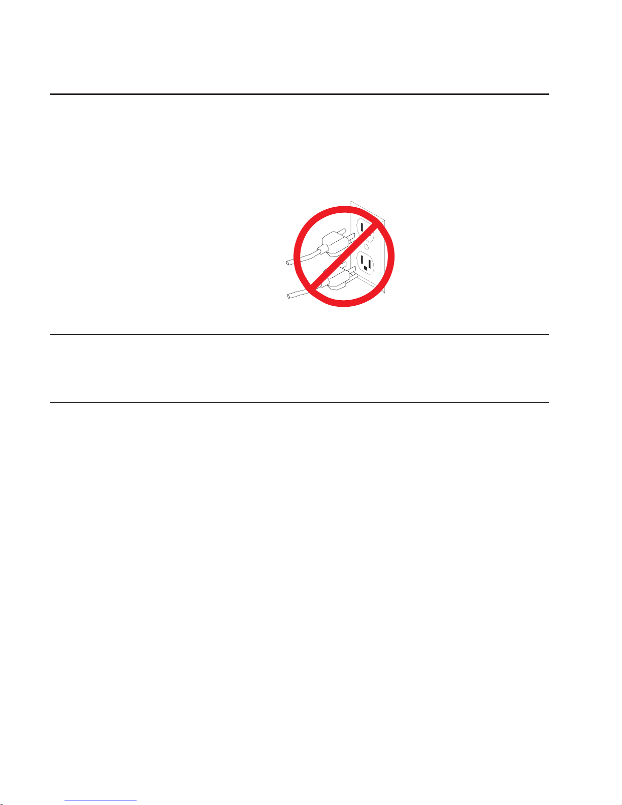
DANGER
To prevent electrical shock hazard, disconnect the power cable
Unit Emissions
The unit-related emission value is equal to or lower than 70dB(A).
Der Geräuschpegel der Einheit ist kleiner oder gleich 70 db(A).
Laser Safety Information
The optical drive in this system unit is a laser product. The optical drive has a label that
identifies its classification. The label, located on the drive, is shown below.
The optical drive in this system unit is certified in the U.S. to conform to the
requirements of the Department of Health and Human Services 21 Code of Federal
Regulations (DHHS 21 CFR) Subchapter J for Class 1 laser products. Elsewhere, the
drive is certified to conform to the requirements of the International Electrotechnical
Commission (IEC) 825 (1st edition 1984) and CENELEC EN 60 825:1991 for Class 1
laser products.
CAUTION:
A class 3 laser is contained in the device. Do not attempt to operate the drive
while it is disassembled. Do not attempt to open the covers of the drive as it is
not serviceable and is to be replaced as a unit.
Class 1 laser products are not considered to be hazardous. The optical drive contains
internally a Class 3B gallium-arsenide laser that is nominally 30 milliwatts at 830
nanometers. The design incorporates a combination of enclosures, electronics, and
redundant interlocks such that there is no exposure to laser radiation above a Class 1
level during normal operation, user maintenance, or servicing conditions.
CLASS 1 LASER PRODUCT
LASER KLASSE 1
LUOKAN 1 LASERLAITE
APPAREIL A LASER DE CLASSE 1
IEC 825:1984 CENELEC EN 60 825:1991
viii 44P Series Model 170 Installation Guide
Page 9

Data Integrity and Verification
IBM computer systems contain mechanisms designed to reduce the possibility of
undetected data corruption or loss. This risk, however, cannot be eliminated. Users who
experience unplanned outages, system failures, power fluctuations or outages, or
component failures must verify the accuracy of operations performed and data saved or
transmitted by the system at or near the time of the outage or failure. In addition, users
must establish procedures to ensure that there is independent data verification before
relying on such data in sensitive or critical operations. Users should periodically check
the IBM support websites for updated information and fixes applicable to the system and
related software.
ix
Page 10

x 44P Series Model 170 Installation Guide
Page 11

About This Book
This book provides information on how to set up your system, install and remove
options, use diagnostics and service aids, as well as verify system operation. This book
also provides information to help you solve some of the simpler problems that might
occur.
ISO 9000
ISO 9000 registered quality systems were used in the development and manufacturing
of this product.
Online Publications
RS/6000 publications are available online. To access the online books, visit our Web
site at: http://www.rs6000.ibm.com/resource/hardware_docs/
Related Publications
The following publications provide additional information about your system unit:
v The
RS/6000 44P Series Model 170 User’s Guide
, order number SA38-0559,
contains information to help users set up their system unit, install, configure, and
modify options, and solve minor problems.
v The
RS/6000 44P Series Model 170 Service Guide
, order number SA38-0560,
contains reference information, maintenance analysis procedures (MAPs), error
codes, removal and replacement procedured, and a parts catalog.
v
Diagnostic Information for Multiple Bus Systems
, order number SA38-0509, contains
diagnostic information, service request numbers (SRNs), and failing function codes
(FFCs).
v The
IBM RS/6000 Adapters, Devices, and Cable Information for Multiple Bus
Systems
, order number SA38-0516, contains information about adapters, devices,
and cables for your system. This manual is intended to supplement the service
information found in the
Diagnostic Information for Multiple Bus Systems
.
v The
Site and Hardware Planning Guide
, order number SA38-0508, contains
information to help you plan your installation.
v The
PCI Adapter Placement Reference
, order number SA38-0538, contains
information about PCI adapter placement in your system unit.
Trademarks
The following terms are trademarks of International Business Machines Corporation in
the United States, other countries, or both:
v AIX
v RS/6000
xi
Page 12

Other company, product, and service names may be trademarks or service marks of
others.
xii 44P Series Model 170 Installation Guide
Page 13

Chapter 1. Setting Up the RS/6000 44P Series Model 170
Follow the procedures in this chapter to install the RS/6000 44P Series Model 170.
Unpacking Your System Unit
CAUTION:
This unit weighs between from 18 kg (39.7 pounds) and 32 kg (70.5 pounds). Two
persons are required to safely move it. Using less than two persons to move it
can result in injury.
1. Remove the top cover of the system unit carton.
2. Lift the system unit out of the carton base.
Step 1: Check Your Inventory
h Books, CD-ROM &
other media
h ″About Your
Machine″ document
h System unit h Display and system
unit power cables (2)
h 9-pin to 25-pin serial
converters (2)(optional)
hSCSI converter cable
(optional)
hASCII terminal
(optional)
hKeyboard (optional)
Wrist/palm rest
(optional)
hDisplay and cable
toroid (optional)
hMouse (optional)
1
Page 14
Step 2: Read the Safety Notices
Safety Note: Before continuing, refer to the System Unit Safety Information book for
Danger and Caution notices. Do not plug any cables into the system unit,
adapters, or electrical outlets until you have reviewed this information.
Make sure none of the power cords are connected before continuing to
the next step.
Step 3: Need Help?
If you encounter difficulties while setting up your system unit, contact your sales
representative for assistance.
Step 4: Are All of the Internal Options Installed?
These instructions are for RS/6000 44P Series Model 170 systems that have internal
options (such as adapters, disk drives, or memory upgrades) already installed. If you
have internal options that are not installed, go to “Chapter 3. Installing Options for the
RS/6000 44P Series Model 170” on page 21, then return to “Step 5: Position the
System Unit and Display” on page 3.
2 44P Series Model 170 Installation Guide
Page 15

Step 5: Position the System Unit and Display
Position the system unit and display (optional) at or near their finished location.
Observe the following guidelines when positioning the system unit and display:
v Leave enough space around the system unit to safely and easily complete the setup
procedures.
v Observe standard ergonomic guidelines while arranging your system unit so that you
can work comfortably and safely. For more information on arranging your workstation,
visit the Healthy Computing Web site at: http://www.pc.ibm.com/us/healthycomputing
v The system unit weighs between 17.7 kg (39 pounds) and 20.4 kg (45 pounds). Two
people are recommended to safely move it. Using less than two persons to move it
can result in injury or damage to the machine.
v Be sure to maintain at least 76 mm (3 inches) of space in front and behind the
system unit to allow the system unit to cool properly. Blocking the air vents can
cause overheating, which might result in a malfunction or permanent damage to the
system unit.
v Place the system unit in a location where it can safely and easily reach any
necessary power outlets and network connections.
v Displays or ASCII terminals can weigh as much as 35 kg (77 pounds). Use caution
when lifting or moving the display or ASCII terminal.
v Place the display or ASCII terminal in a stable and sturdy location.
Step 6: Check Your Display Type
If you ordered a display with your system unit, the system unit has been set to use the
highest display resolution and refresh rate available for that display. If you want to:
v Attach a different display to your system unit
v Change the default display resolution or refresh rate
then after completing the installation steps, refer to the Customer Installable Options
Library CD-ROM for the documentation on the graphics adapter to learn how to change
the settings for the display you are installing.
Chapter 1. Setting Up the RS/6000 44P Series Model 170 3
Page 16

Step 7: Connect the Display
Connect the graphics display cable to the back of the display and to the graphics
adapter connector.
For more display instructions, see your display documentation.
Note: Some displays require an additional cable.
If you have an ASCII terminal, you must connect it to the serial connector S1, but do
not connect it at this time. Wait until you reach “Step 12: Connect the Serial and
Parallel Devices” on page 8 for instructions.
Step 8: Attach the Display Cable Toroid
If the cable for your display does not include a toroid, locate the toroid shipped with
your system unit and follow the installation instructions included with the toroid.
.
4 44P Series Model 170 Installation Guide
Page 17

Step 9: Connect the Adapter Cables
If you are using any optional adapters (such as Token-Ring or 8-port EIA-232), connect
the cables to the appropriate connectors in slots 1 through 6.
Chapter 1. Setting Up the RS/6000 44P Series Model 170 5
Page 18

Step 10: Connect the First External SCSI Device
If you need to connect an external SCSI device, follow these steps. If you ordered the
optional SCSI converter cable and need it to connect an external SCSI device, begin
with step 1. If you do not need the converter cable, begin with step 3. If you have no
external SCSI devices to attach, skip to “Step 12: Connect the Serial and Parallel
Devices” on page 8.
1. Connect the Ultra 2 SCSI end of the converter cable directly to the system unit.
2. Connect the other end of the SCSI converter cable to one end of the SCSI device
cable.
3. Connect the other end of the SCSI device cable to the SCSI device.
4. Connect the SCSI device terminator (if this is the last device to be connected). The
last device on a SCSI bus
must
be terminated.
Note: When a cable is not attached to the SCSI connector on the system unit, the
connector is automatically terminated (internally).
5. Refer to the SCSI device documentation to set the SCSI device address. For future
reference, you can record the address in “Appendix D. System Records” on
page 61.
2
3
4
1
2
6 44P Series Model 170 Installation Guide
Page 19

Step 11: Connect Additional External SCSI Devices
1. Locate the last SCSI device in the chain from the system unit. Remove the SCSI
device terminator (if it is installed).
2. Connect the new SCSI cable where you just removed the SCSI device terminator.
3. Connect the other end of the SCSI cable to the new SCSI device.
4. Connect the SCSI device terminator.
5. Repeat the above steps for each additional SCSI device you attach.
6. Refer to the SCSI device documentation to set the SCSI device address. For future
reference, you can record the address in “Appendix D. System Records” on
page 61.
Chapter 1. Setting Up the RS/6000 44P Series Model 170 7
Page 20
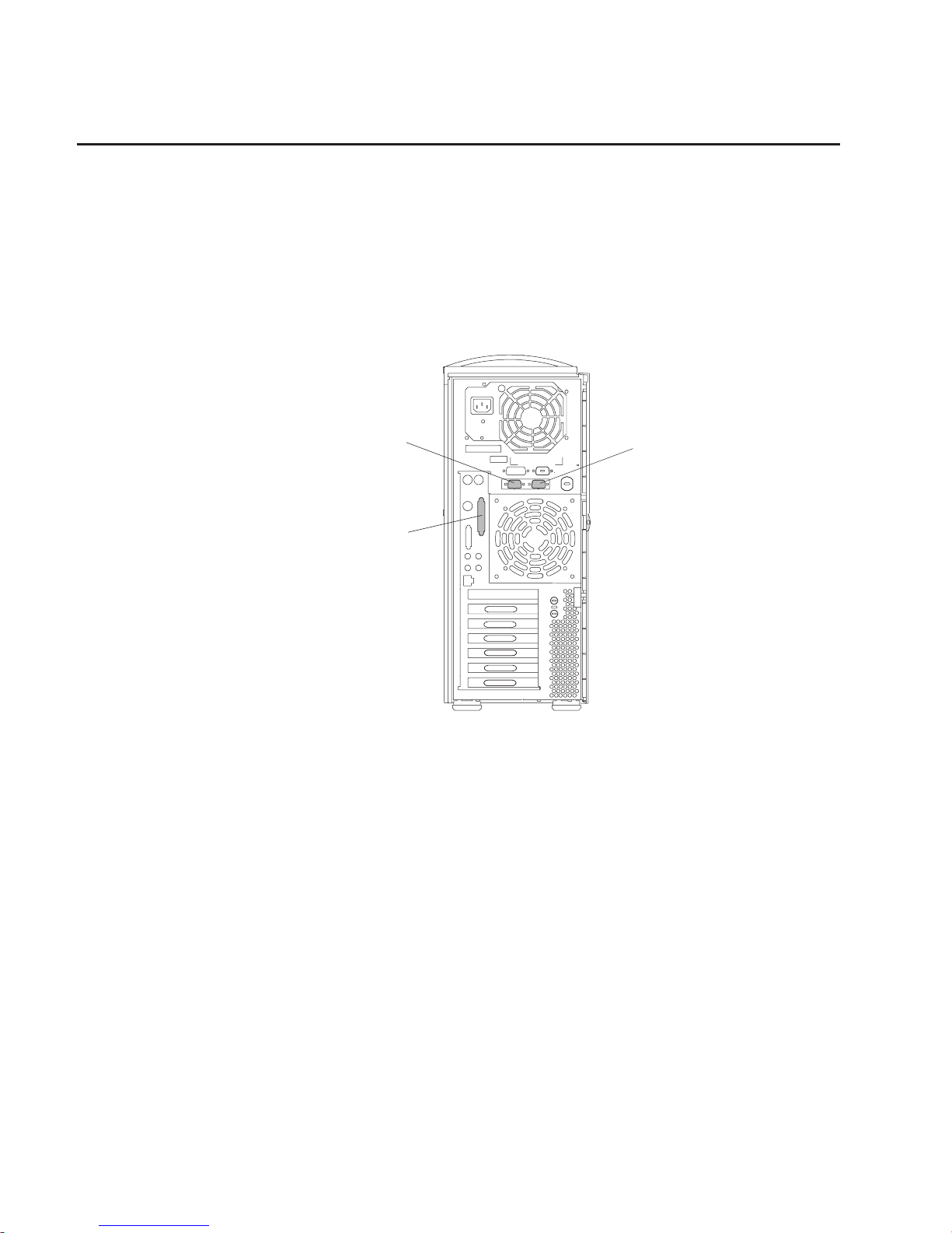
Step 12: Connect the Serial and Parallel Devices
If you have a parallel device (such as a printer), connect it to the parallel connector.
If you have one serial device, connect it to the serial connector S1. If you have an
ASCII terminal, you must connect it to the serial connector S1. An additional serial
device can be connected to the S2 connector.
Two 9-to-25-pin serial converters are optional with your system unit to increase serial
device compatibility.
1
3
2
1 S1 Serial Connector
2 S2 Serial Connector
3 Parallel Connector
8 44P Series Model 170 Installation Guide
Page 21

Step 13: Connect the Keyboard, Mouse, and Tablet
If you are using a keyboard, mouse, tablet, or other input device with your system unit,
connect them to the appropriate connectors.
If a wrist/palm rest was included with your keyboard and you want to attach it, refer to
the keyboard documentation for installation instructions.
Chapter 1. Setting Up the RS/6000 44P Series Model 170 9
Page 22

Step 14: Connect the Audio Cables
If you are using earphones, microphone, or audio equipment, connect the cables to the
appropriate connector.
1
2
4
3
1 Audio line in
2 Audio line out
3 Headphone
4 Microphone
10 44P Series Model 170 Installation Guide
Page 23

Step 15: Are You Using an Ethernet Connection?
Ask your system administrator if you are unsure whether you are using an Ethernet
connection. If you already connected your ethernet to an adapter in “Step 9: Connect
the Adapter Cables” on page 5, or if you are not using Ethernet, go to “Step 18: Plug in
the Power Cables” on page 15.
To connect the Ethernet cable, first determine which kind you have:
v For Twisted-Pair (RJ-45,10/100 Base T), go to “Step 16: Connect Twisted-Pair
Ethernet” on page 12.
v For Thick (AUI - 10 Base 5), go to “Step 17: Connect Thick Ethernet” on page 13.
Chapter 1. Setting Up the RS/6000 44P Series Model 170 11
Page 24

Step 16: Connect Twisted-Pair Ethernet
Note: The twisted-pair connecter is compatible with the IEEE 802.3 Ethernet network
(10 Base T, 100 Base TX links enabled).
1. Connect the twisted-pair cable to the twisted-pair connector.
2. The twisted-pair Ethernet cable is now installed; go to “Step 18: Plug in the Power
Cables” on page 15.
12 44P Series Model 170 Installation Guide
Page 25

Step 17: Connect Thick Ethernet
1. Connect your thick Ethernet cable to the thick Ethernet connector.
Chapter 1. Setting Up the RS/6000 44P Series Model 170 13
Page 26

2. Lock the thick cable to the Ethernet connector by sliding the Ethernet connector
toward the large notch.
3. The thick Ethernet cable is now installed. Go to “Step 18: Plug in the Power Cables”
on page 15.
14 44P Series Model 170 Installation Guide
Page 27

Step 18: Plug in the Power Cables
1. Plug the power cable into the system unit.
2. Plug the power cables into the display and attached devices.
3. Plug these power cables into electrical outlets.
CAUTION:
This product is equipped with a three-wire power cable and plug for your
safety. Use this power cable with a properly grounded electrical outlet to
avoid electrical shock.
4. Wait for the operator panel to display OK.
Chapter 1. Setting Up the RS/6000 44P Series Model 170 15
Page 28

Step 19: Your System Unit Is Now Set Up
Arrange your system unit and attached devices so you can use them comfortably. For
more information on arranging your workstation, visit the Healthy Computing Web site
at: http://www.pc.ibm.com/us/healthycomputing
To power on your system unit, open the front panel and press the white power switch.
When you press the Power On switch, the Power On LED comes on and the system
starts a POST (power-on self test). During POST, progress codes display in the
operator panel display.
If the Power On light does not come on and there is no indication of power when you
press the Power On switch, ensure that the power cord, located at the back of the
system unit, is plugged into a grounded electrical outlet. If this does not solve the
problem, go to the ″Hardware Problem Determination″ chapter in the
RS/6000 44P
Series Model 170 User’s Guide
, order number SA38-0559. If the LED is not glowing
and OK is not displayed in the display, go to the ″Using the Stand-alone and Online
Diagnostics″ chapter, also in the User’s Guide.
Note: Be sure to maintain at least 76 mm (3 inches) of space at the rear of the system
unit to allow for proper cooling.
Step 20: Go to Your Operating System Documentation
If an operating system has been preinstalled in your RS/6000 44P Series Model 170
system, or if you are installing one, refer to the operating system installation
documentation.
16 44P Series Model 170 Installation Guide
Page 29

Chapter 2. Verifying the Hardware Operation
Use the system verification procedure to check the system for correct operation.
If you are analyzing a hardware problem, use
RS/6000 44P Series Model 170 Service
Guide
, order number SA38-0560.
Step 1. Considerations before Running This Procedure
Notes:
1. If this system unit is directly attached to another system unit or attached to a
network, make sure that communications with the other system unit are stopped.
2. This procedure requires use of all of the system resources. No other activity can be
running on the system while you are doing this procedure.
This procedure requires a display connected to the video port or an ASCII terminal
attached to the S1 port.
1. Before starting this procedure, stop all programs and the operating system.
2. This procedure runs the Online Diagnostics in Service mode or Stand-alone
Diagnostics. If the Online Diagnostics are installed, they should be run. See the
operator manual for your type of ASCII terminal to find the key sequences you need
to respond to the diagnostics.
3. If you need more information about diagnostics, see ″Using the Stand-alone and
Online Diagnostics″ in the
RS/6000 44P Series Model 170 User’s Guide
, order
number SA38-0559.
Step 2. Loading the Diagnostics
1. Stop all application programs running on the operating system.
2. Stop the operating system.
3. Turn off the power.
4. If you are loading the Stand-alone Diagnostics and running them from an ASCII
terminal, do the following:
v The attributes for the terminal must be set to match the defaults of the
diagnostics.
v If you need to change any settings, record the normal settings, and be sure the
terminal attributes are set to work with the diagnostics. If needed, see
“Appendix E. General Attributes Required When Using a TTY Terminal” on
page 65.
5. Turn on the power.
a. When the keyboard indicator appears, press F5 on the directly attached
keyboard (5 on the ASCII keyboard) to load the Stand-alone Diagnostics or F6
on the directly attached keyboard (6 on the ASCII terminal keyboard) to load the
Online Diagnostics.
17
Page 30

b. Enter any requested passwords.
c. Follow the instructions to select a console.
6. When the Diagnostic Operating Instructions display, go to Step 3. If you are unable
to load the diagnostics, go to ″Problem Determination When Unable to Load
Diagnostics″ in the
RS/6000 44P Series Model 170 User’s Guide
, order number
SA38-0559.
Step 3. Running System Verification
1. On the Diagnostic Operating Instructions screen, press the Enter key.
2. If the terminal type has not been defined, use the Initialize Terminal option on the
Function Selection menu to initialize the operating system environment before you
can continue with the diagnostics.
3. If you want to do a general checkout with minimal operator action, select the
Diagnostic Routines option on the Function Selection menu.
If you want to do a more complete checkout including the use of wrap plugs, select
the Advanced Diagnostics option on the Function Selection menu. The advanced
diagnostics are primarily for the service representative; they may instruct you to
install wrap plugs to better isolate a problem.
4. Select the System Verification option on the Diagnostic Mode Selection menu.
5. If you want to run a general checkout of all installed resources, select the All
Resource option on the Diagnostic Selection menu.
If you want to check one particular resource, select that resource on the Diagnostic
Selection menu.
Step 4. Additional System Verification
The checkout programs end with either the Testing Complete menu and a message
stating No trouble was found or the A Problem Was Detected On (Time Stamp) menu
with a SRN (service request number).
1. Press Enter to return to the Diagnostic Selection menu.
2. If you want to check other resources, select the resource.
Step 5. Stopping the Diagnostics
1. If you are running Online diagnostics, shut down the system using the following
procedure:
a. Press F3 repeatedly until you get to the Diagnostic Operating Instructions, then
follow the displayed instructions.
b. Press F3 once, and then follow the displayed instructions to shut down the
system.
2. If you changed any attributes on your ASCII terminal to run the diagnostics, change
the settings back to normal.
18 44P Series Model 170 Installation Guide
Page 31

3. This completes the system verification. Report the SRN, if you received one, to the
service organization. To do a normal boot, turn off the system unit and wait 30
seconds, and then set the power switch of the system unit to On.
Chapter 2. Verifying the Hardware Operation 19
Page 32

20 44P Series Model 170 Installation Guide
Page 33

Chapter 3. Installing Options for the RS/6000 44P Series Model 170
This chapter provides instructions to help you add options to your system. Some
option-removal instructions are provided, in case you need to remove one option to
install another. If you have several internal options to install, you might want to add
them all before reassembling the system.
Safety Considerations
Observe the following safety precautions anytime you work with this system unit.
DANGER
An electrical outlet that is not correctly wired could place hazardous voltage
on metal parts of the system or the devices that attach to the system. It is the
responsibility of the customer to ensure that the outlet is correctly wired and
grounded to prevent an electrical shock.
Before installing or removing signal cables, ensure that the power cables for
the system unit and all attached devices are unplugged.
When adding or removing any additional devices to or from the system,
ensure that the power cables for those devices are unplugged before the
signal cables are connected. If possible, disconnect all power cables from the
existing system before you add a device.
Use one hand, when possible, to connect or disconnect signal cables to
prevent a possible shock from touching two surfaces with different electrical
potentials.
During an electrical storm, do not connect cables for display stations, printers,
telephones, or station protectors for communications lines.
CAUTION:
This product is equipped with a 3-wire power cable and plug for the user’s safety.
Use this power cable in conjunction with a properly grounded electrical outlet to
avoid electrical shock.
Handling Static-Sensitive Devices
Attention: Adapters, planars, diskette drives, and disk drives are sensitive to static
electricity discharge. These devices are wrapped in antistatic bags to prevent this
damage.
Take the following precautions:
v If you have an antistatic wrist strap available, use it while handling the device.
21
Page 34

v Do not remove the device from the antistatic bag until you are ready to install the
device in the system unit.
v With the device still in its antistatic bag, touch it to a metal frame of the system.
v Grasp cards and boards by the edges. Hold drives by the frame. Avoid touching the
solder joints or pins.
v If you need to lay the device down while it is out of the antistatic bag, lay it on the
antistatic bag. Before picking it up again, touch the antistatic bag and the metal
frame of the system unit at the same time.
v Handle the devices carefully in order to prevent permanent damage.
Stopping the System Unit
Attention: When using the shutdown procedure for your system, follow the correct
shutdown procedure before you stop the system unit. Failure to do so can
result in the loss of data.
1. At a command line, enter shutdown -F to stop the operating system.
2. After you shut down the operating system, set the power switches of any attached
devices to Off.
22 44P Series Model 170 Installation Guide
Page 35

Covers
Before performing these procedures, read “Safety Notices” on page vii.
Use the following steps when removing or replacing the left side cover.
Removing the Left Side Cover
1. Shut down the system as described in “Stopping the System Unit” on page 22.
2. Unplug the power cable.
3. Turn the key lock on the rear cover of the system unit to the unlocked position.
4. Place your index finger behind the left cover detent located toward the rear of the
system unit.
Keylock
(Shown in the unlocked position)
Keylock
(Shown
in the unlocked position
)
Chapter 3. Installing Options for the RS/6000 44P Series Model 170 23
Page 36

5. Gently pull the cover detent out (away from the rear of the system unit), then slide
the cover toward the front of the machine. This action releases the slide tabs that
hold the cover to the chassis.
Cover DetentCover Detent
24 44P Series Model 170 Installation Guide
Page 37

Replacing the Left Side Cover
To replace the left side cover, do the following:
1. Align and insert the three slide tabs on the bottom of the side cover into their
respective slots on the chassis.
2. Rotate the cover into place, ensuring that the remaining slide tabs are aligned and
inserted.
3. Slide the cover toward the rear of the chassis, ensuring that the cover lays flat
against the chassis. The detent latches the cover, keeping it from sliding toward the
front of the machine.
4. Rotate the keylock located on the back of the system into the locked position.
Chapter 3. Installing Options for the RS/6000 44P Series Model 170 25
Page 38

Cover Support Bridge
The support bridge might need to be removed to access the inside of the machine. Use
the following steps when removing or replacing the support bridge.
Removing the Cover Support Bridge
1. Shut down the system as described in “Stopping the System Unit” on page 22.
2. Unplug the system unit power cable from the electrical outlet.
3. Remove the left side cover as described in “Removing the Left Side Cover” on
page 23.
4. Remove the screw securing the cover support bridge.
5. Pivot the cover support bridge out from front to back and then remove from the
system unit.
Replacing the Cover Support Bridge
To replace the cover support bridge, perform the removal steps in reverse order.
26 44P Series Model 170 Installation Guide
Page 39

Battery
Use the following steps to remove or replace the battery.
CAUTION:
A lithium battery can cause fire, explosion, or a severe burn. Do not recharge,
disassemble, heat above 100°C (212°F), solder directly to the cell, incinerate, or
expose cell contents to water. Keep away from children. Replace only with the
part number specified for your system. Use of another battery may present a risk
of fire or explosion.
The battery connector is polarized; do not attempt to reverse polarity.
Dispose of the battery according to local regulations.
Removing the Battery
1. Shut down the system unit as described in “Stopping the System Unit” on page 22.
2. Unplug the power cable.
3. Remove the left side cover as described in “Removing the Left Side Cover” on
page 23.
Note: To prevent damage to your machine, you can lay it on its side. Do not knock
the machince over.
4. Remove the cover support bridge as described in “Cover Support Bridge” on
page 26.
5. Locate the battery on the system board.
Chapter 3. Installing Options for the RS/6000 44P Series Model 170 27
Page 40

6. Remove any adapters that prevent access to the battery, as described in “Removing
Adapters” on page 36.
7. Pry the battery out of its mount using your fingernail or a small, blunt object. After
the top of the battery has cleared the plastic mount, pull it up and out of the system.
Note: You may need to pry the battery out of the mount after the top of the battery
has cleared the battery mount.
Do not
wiggle the plastic mount from side to
side or try to separate the plastic battery mount from the system board. The
plastic mount connections are soldered to the system board.
Permanent
damage may result to the system board if the battery mount is damaged or
removed.
System customizations, such as passwords, and time and date settings, may be lost
when the battery is removed.
Replacing the Battery
Note: If possible, use a cloth or tissue to handle the new battery. Body oils can cause
early battery failure.
1. Ensure that the battery polarity is correct. With the positive (+) side of the
battery facing the memory module connectors, insert the battery between
the front and rear battery mount clips.
2. Using your thumb, gently press the battery into the battery mount. Use your
index finger to support the back of the battery mount during this step.
3. Replace adapters, if you removed any.
Rear Battery ClipRear Battery Clip
Memory
Module
Connectors
Memory
Module
Connectors
Plastic Battery MountPlastic Battery Mount
Battery
28 44P Series Model 170 Installation Guide
Page 41

4. If you have additional options to install, refer to “Option List” on page 30 for
the appropriate page number, and skip to that section. Otherwise, continue
with these steps.
5. Replace the cover support bridge as described in “Replacing the Cover
Support Bridge” on page 26.
6. Replace the left side cover as described in “Replacing the Left Side Cover”
on page 25.
7. Reconnect all removed cables.
8. Turn on the power.
9. You may have to enter SMS to restore the bootlist in order to boot AIX. The
bootlist command may need to be run while you are logged in as root
user. This restores the custom bootlist and allows the option of
Select
Software
under multiboot to start the operating system. IP (Internet
Protocol) parameters may also need to be rebuilt. Refer to your AIX
documentation for instructions.
10. After booting AIX, log in as root user. Reset the time and date using the
date command. (Type: date ?).
Chapter 3. Installing Options for the RS/6000 44P Series Model 170 29
Page 42

Option List
v Removing Memory Modules, see page 30.
v Installing Memory Modules, see page 32.
v Removing the Processor Card, see page 34.
v Installing the Processor Card, see page 35.
v Removing Adapters, see page 36.
v Installing Adapters, see page 38.
v Internal Drives, see page 40.
v Removing Disk Drives, see page 42.
v Installing Disk Drives, see page 43.
v Configuration or Unconfiguration of Media Drives see page 41.
v Removing a CD-ROM Drive, Tape Drive, Diskette Drive, see page 45.
v Installing a CD-ROM Drive, Tape Drive, Diskette Drive, see page 45.
v Using Optional Media, see page 46.
v Installing Optional Media, see page 48.
v Installing the Optional Media Fan Assembly, see page 49.
v Performing System Firmware Updates, see page 51.
Memory Modules
Before performing these procedures, read “Safety Notices” on page vii. Use the
following steps when removing or installing memory modules.
Removing Memory Modules
Note: Memory modules are located on the system board. You can want to lay the
machine on its side for easier access to the modules.
1. Shut down the system as described in “Stopping the System Unit” on
page 22.
2. Unplug the power cable.
3. Remove the left side cover as described in “Removing the Left Side Cover”
on page 23.
4. Remove the cover support bridge as described in “Removing the Cover
Support Bridge” on page 26.
5. Before handling any card, board, or memory module, use one hand to touch
any metal surface of the chassis to minimize static electrical charges.
30 44P Series Model 170 Installation Guide
Page 43

6. Locate the memory module connectors and determine which module you
want to remove.
7. Remove the memory module by gently pushing the tabs out and then down.
The tabs begin forcing the memory card out of the connector.
8. Finish this procedure by pulling the card out of the connector and system
unit.
Memory Modules Pair A
Connector Locations
Memory Modules Pair A
Connector
Locations
Memory Modules Pair B
Connector Locations
Memory
Modules Pair B
Connector
Locations
J10
J2
J9
J1
J1
Pair-A-DIMM1
Pair-B-DIMM1
Pair-A-DIMM2
Pair-B-DIMM2
J9
J2
J10
Chapter 3. Installing Options for the RS/6000 44P Series Model 170 31
Page 44

Installing Memory Modules
Notes:
1. Memory modules must be installed in pairs and in the correct slot configuration.
(Slots J1 and J2 are a pair, and slots J9 and J10 are a pair.) Refer to the illustration
in step 6 on page 31.
2. If you are replacing one DIMM of a pair, be sure to use the same FRU part number
as the good DIMM. If this is not possible, replace the pair with a matched pair.
Push Locking Tabs
Out to Release Memory
Module
1
2
1
32 44P Series Model 170 Installation Guide
Page 45

Before performing these procedures, read “Safety Notices” on page vii. Use the
following steps when removing or installing memory modules.
1. With one hand, touch any metal surface of the chassis to minimize static electrical
charges, and then pick up the memory module.
2. Locate the memory module connector on the system board.
3. Ensure that the locking tabs are open.
4. Insert the memory module firmly into the connector. The locking tabs located on
each end of the memory module connector move back into the locked position.
5. Ensure that the locking tabs are in the secure position. (Tabs are in the secure
position when they are parallel to the side of the connector.)
6. If you have additional options to install, refer to “Option List” on page 30 for the
appropriate page number, and skip to that section. Otherwise, continue with these
steps.
7. Replace the cover support bridge as described in “Replacing the Cover Support
Bridge” on page 26.
8. Replace the system unit left cover as described in “Replacing the Left Side Cover”
on page 25.
9. Reconnect all cables.
10. Turn on the power.
Chapter 3. Installing Options for the RS/6000 44P Series Model 170 33
Page 46

Processor Card
Before performing these procedures, read “Safety Notices” on page vii. Use the
following steps when removing or installing the processor card.
Removing the Processor Card
Attention: Your system unit may require updating the firmware. A diskette or CD-ROM
is included with your new processor card if that is required. Refer to
“System Firmware Updates” on page 51.
1. Shut down the system as described in “Stopping the System Unit” on page 22.
2. Unplug the power cable.
3. Remove the left side cover described in “Removing the Left Side Cover” on
page 23.
4. Remove the cover support bridge as described in “Removing the Cover Support
Bridge” on page 26.
5. Unplug the power connector (P11) from the processor card connector (J8).
6. Pull up on the two snap buttons located on each side of the processor card.
Snap ButtonSnap Button
34 44P Series Model 170 Installation Guide
Page 47

7. Pull on the blue plastic card handle until the card is unseated from the connector.
Note: Grasp only the blue plastic handle.
Do not
push, pull or grasp the voltage
regulator, which is located just below the blue handle on the underside of the
processor card. Refer to “Handling Static-Sensitive Devices” on page 21 for
instructions on handling static-sensitive devices.
8. Remove the card from the system unit.
Installing the Processor Card
Attention: Installing the processor card requires some force. To prevent damage to
your machine, lay it on its side before installing the card. Do not knock the machine
over.
1. Ensure that the snap buttons are pulled up.
2. Carefully align the processor card with the card connector.
3. Press firmly on the blue plastic handle to insert the processor card into the card
connector.
Note:
Do not
press on the snap buttons or voltage regulator while inserting the
card into the connector.
4. After the processor card is correctly seated into the connector, press the snap
buttons into their locking position. The snap buttons make a clicking sound when
securely fastened.
5. Plug the power cable (P11) into the processor card connector (J8).
6. If you have additional options to install, refer to “Option List” on page 30 for the
appropriate page number, and skip to that section. Otherwise, continue with these
steps.
7. Replace the cover support bridge as described in “Replacing the Cover Support
Bridge” on page 26.
8. Replace the left side cover as described in “Replacing the Left Side Cover” on
page 25.
9. Reconnect all cables.
10. Turn on the power.
Voltage RegulatorVoltage Regulator
Heatsink FanHeatsink
Fan
J8
Chapter 3. Installing Options for the RS/6000 44P Series Model 170 35
Page 48

Adapters
Before performing these procedures, read “Safety Notices” on page vii. Use the
following steps when removing or installing adapters.
Removing Adapters
1. Shut down the system as described in “Stopping the System Unit” on page 22.
2. Unplug the power cable.
3. Remove the left side cover as described in “Removing the Left Side Cover” on
page 23.
4. Record the slot number and location of the adapter being removed.
Note: Adapter slots are numbered from top to bottom, one through six, on the rear
of the system unit. Refer to “Handling Static-Sensitive Devices” on page 21
for instructions on handling static-sensitive devices.
5. Label and disconnect all cables attached to the adapter being removed.
36 44P Series Model 170 Installation Guide
Page 49

6. Remove the PCI shield by reaching behind the shield and gently pulling on the two
pull tabs. Refer to the illustration on page 37.
7. If you are removing full-length adapters, then retract the adapter retention bar
which is built into the lower front fan housing. Refer to the illustration on page 37.
8. Remove the adapter bracket retaining screw.
9. With one hand, touch any metal surface of the chassis to minimize static electric
discharge.
10. Remove the adapter from the system unit.
11. If you are installing another adapter in this slot location, skip to step 8 on page 38.
If you are not, replace the expansion-slot cover and screw, if available.
12. Replace the PCI shield with the pull tabs facing inside the system unit.
13. If you have additional options to install, refer to “Option List” on page 30 for the
appropriate page number, and skip to that section. Otherwise, continue with these
steps.
Card Retention Bar Lever
in the Opened Position
Card Retention Bar Lever
in
the Opened Position
PCI ShieldPCI Shield
Adapter Bracket
Retaining Screws
Adapter
Bracket
Retaining
Screws
Card Retention Bar Lever
in the Closed Position
Card
Retention Bar Lever
in
the Closed Position
Retention Bar Lever
Retaining Clip
Retention Bar Lever
Retaining
Clip
Chapter 3. Installing Options for the RS/6000 44P Series Model 170 37
Page 50

14. Replace the left side cover as described in “Replacing the Left Side Cover” on
page 25 .
15. Reconnect all cables.
16. Turn on the power.
Installing Adapters
When installing an adapter, do the following:
1. Shut down the system unit as described in “Stopping the System Unit” on page 22.
2. Unplug the power cable.
3. Remove the left side cover as described in “Removing the Left Side Cover” on
page 23.
4. Before handling the adapter, use one hand to touch any metal surface of the
chassis to minimize static electrical charges. Refer to “Handling Static-Sensitive
Devices” on page 21 for instructions on handling static-sensitive devices.
5. Remove the PCI shield by reaching behind the shield and gently pulling on the two
pull tabs. Refer to the illustration on page 37.
6. Remove the expansion slot cover.
7. If you are installing full-length adapters, then retract the adapter retention bar,
which is built into the lower-front fan housing. Refer to the illustration on page 37.
8. Carefully grasp the adapter by the edges and align the adapter with the
expansion-slot connector.
9. Press the adapter firmly into the expansion-slot connector.
10. Use the screw you removed earlier from the expansion-slot cover to secure the
adapter bracket to the system unit.
11. Press in the retention bar retaining clip to engage the card retention bar on the
lower-front fan housing (for full-length adapters).
If you have additional adapters to install, repeat steps 4 through 9.
12. Replace the PCI shield with the pull tabs facing inside the system unit.
13. If you have additional options to install, refer to “Option List” on page 30 for the
appropriate page number, and skip to that section. Otherwise, continue with these
steps.
14. Reconnect all cables.
15. Replace the left side cover as described in “Replacing the Left Side Cover” on
page 25.
38 44P Series Model 170 Installation Guide
Page 51

Card Retention Bar Lever
in the Opened Position
Card Retention Bar Lever
in
the Opened Position
Retention Bar Lever
Retaining Clip
Retention
Bar Lever
Retaining
Clip
Chapter 3. Installing Options for the RS/6000 44P Series Model 170 39
Page 52

Internal Drives
The 44P Series Model 170 has six drive bays:
v One 3.5 inch diskette bay
v Two 5.25 inch media bays, for CD-ROM drives, tape drives, or disk drives
v Three 1 inch or two 1.5 inch disk drive bays
A diskette drive and CD-ROM drive are preinstalled in most system units. There is an
optional disk drive carrier, which is necessary to add an optional disk drive in the media
bay.
Checklist for Handling Drives
Consider the following cautions when installing or removing media drives:
v Use caution when handling all disk drives. Disk drives are more likely to be damaged
during installation and service than at any other time. A fall of as little as .25 inch,
bumping, or rough handling can cause latent failures.
v Media drives are particularly sensitive to electrostatic discharge. Follow the
electrostatic handling procedures before handling the media drive. Refer to “Handling
Static-Sensitive Devices” on page 21.
v Refer to the documentation provided with your drive to determine if any drive-specific
procedures must be followed, such as setting switches or jumpers, or attaching the
drive to a carrier tray.
Disk Drive BaysDisk Drive Bays
Operator Panel and
Diskette Drive Bays
Operator
Panel and
Diskette
Drive Bays
Optional Media
Drive Bay
Optional
Media
Drive
Bay
CD-ROM Media
Drive Bay
CD-ROM
Media
Drive
Bay
1
2
3
4
5
6
40 44P Series Model 170 Installation Guide
Page 53

v SCSI drives must have their SCSI address set manually. Refer to the documentation
provided with your drive for more information on setting the SCSI address. Refer to
″SCSI IDs and Bay Component Locations″ in the
RS/6000 44P Series Model 170
Service Guide
, order number SA38-0560 for more information on SCSI addresses in
your system unit.
v Ensure no internal SCSI device has a terminator configured on this drive.
Configuring a Drive
Before removing a disk drive, it may be necessary to unconfigure it. After installing a
disk drive, it may be necessary to configure it.
Use the following steps to configure or unconfigure your drives.
Drive Configuring
If you need to configure a disk drive, do the following:
1. Log in as root user.
2. Enter the smit command.
3. Select Devices.
4. Determine the type of disk drive you want to configure. Select that type of drive
from the menu.
5. Select Add a
drive type
, where
drive type
is the type of drive you are configuring.
6. A list provides various models of the drive type you selected. Select the specific
type of drive you are adding.
Drive Unconfiguring
1. Log in as root user.
2. Enter the smit command.
3. Select Devices.
4. Determine the type of disk drive you want to remove or unconfigure. Select that
type of drive from the menu.
5. For the Keep Definition option, select Yes to retain the details of the drive in the
device configuration database.
6. A list provides various models of the drive type you selected. Select the specific
type of drive you are removing.
7. Select the Do option to unconfigure the drive.
Chapter 3. Installing Options for the RS/6000 44P Series Model 170 41
Page 54

Disk Drives
Before performing these procedures, read “Safety Notices” on page vii. Use the
following steps when removing or installing a disk drive.
Removing Disk Drives
1. Unconfigure the drive you wish to remove. See “Drive Unconfiguring” on page 41
for instructions.
2. Shut down the system.
3. Unplug the power cable.
4. Remove the left side cover as described in “Removing the Left Side Cover” on
page 23.
5. Remove the cover support bridge as described in “Removing the Cover Support
Bridge” on page 26.
6. Locate the disk drive cage, as shown in the following illustration.
7. Disconnect the power and SCSI cables from the disk drives.
8. Remove the retaining screw that secures the disk drive cage to the chassis.
9. Remove the disk drive cage and disk drive(s) as a unit.
10. Remove the four screws that secure the disk drive to the disk drive cage
Disk Drive CageDisk Drive Cage
Disk Drive Cage Retaining ScrewDisk
Drive Cage Retaining Screw
42 44P Series Model 170 Installation Guide
Page 55

Note: The screws that secure the disk drive to the disk drive cage are special
shoulder screws, with blue grommets. Failure to use the blue grommets and
shoulder screws can result in permanent damage to the disk drive.
11. Remove the disk drive from the disk drive cage.
Installing Disk Drives
Notes:
1. If you are installing a disk drive in the media bay, go to “Installing an Optional Disk
Drive” on page 48.
2. SCSI drives must have their SCSI address set manually. Refer to the
documentation provided with your disk drive for more information on setting the
SCSI address. Refer to ″SCSI IDs and Bay Component Locations″ in the
RS/6000
44P Series Model 170 Service Guide
, order number SA38-0560 for more
information on SCSI addresses in your system unit.
1. Follow steps 2 through 7 of “Disk Drives” on page 42.
2. Remove or put any termination jumpers in the inactive position.
3. With one hand, touch any metal surface of the chassis to minimize static electric
discharge.
4. Insert the disk drive into the disk drive cage.
Blue GrommetBlue Grommet
Shoulder
Screw
Shoulder
Screw
Disk DriveDisk
Drive
Disk Drive Cage
Retaining Screw
Disk
Drive Cage
Retaining
Screw
Disk Drive Cage
Retaining Screw
Disk
Drive Cage
Retaining
Screw
Chapter 3. Installing Options for the RS/6000 44P Series Model 170 43
Page 56

5. Align the screw holes on the disk drive with the screw holes on the disk drive
cage.
6. Install the four previously removed shoulder screws. Ensure that the blue
grommets are in the correct position.
Note: The screws that secure the disk drive to the disk drive cage are special
shoulder screws. These screws and the blue grommets
must
be used when
installing a disk drive. Failure to use the blue grommets and special
shoulder screws can result in permanent damage to the disk drive. The
shoulder screws and blue grommets must also be used if you are installing
a one-inch high disk drive into the disk drive carrier.
7. Install the disk drive cage back into the system unit.
8. Install the previously removed disk drive cage retaining screw.
9. Reconnect all disk drive cables.
10. If you have additional options to install, refer to “Option List” on page 30 for the
appropriate page number, and skip to that section. Otherwise, continue with these
steps.
11. Replace the cover support bridge. See “Cover Support Bridge” on page 26.
12. Replace the left side cover. See “Replacing the Left Side Cover” on page 25.
13. Reconnect the system power cables.
14. Turn on the power.
15. Reboot, then configure the drive using SMIT. Then wait five minutes for the drive
to warm up. See “Drive Configuring” on page 41 for instructions on configuring the
drive.
44 44P Series Model 170 Installation Guide
Page 57

Media Drives
Use the following steps when removing or replacing a media device.
Attention: Do not open the drive; no user adjustments or serviceable parts are inside.
Removing CD-ROM Drives and Tape Drives
Note: The front cover does not need to be removed to service media devices.
1. Shut down the system as described in “Stopping the System Unit” on
page 22.
2. Unplug the power cable.
3. Remove the left side cover as described in “Removing the Left Side Cover”
on page 23.
4. Remove the air duct located between the power supply and media bay.
5. Remove the screws that secure the media drive to the system unit.
6. Slide the drive forward and out the front of the system.
7. Disconnect the power and data cables from the drive you are removing.
8. If you are removing the upper CD-ROM drive, disconnect the audio cable
from the rear of the CD-ROM drive.
Installing Media Drives
1. The CD-ROM drives and Tape drives are designed to have the cables connected
and disconnected from the front of the system.
v Set the SCSI address jumpers at the rear of the drive to the correct address
before installation. Refer to the documentation provided with your device for
details on setting the SCSI address. Refer to ″SCSI IDs and Bay Component
Locations″ in the
RS/6000 44P Series Model 170 Service Guide
, order number
SA38-0560 for more information on SCSI addresses in your system unit.
CD-ROM DriveCD-ROM Drive
Air DuctAir Duct
Chapter 3. Installing Options for the RS/6000 44P Series Model 170 45
Page 58

v Ensure that no terminator is selected on the drive.
v Locate the SCSI cable. Connect the cable to the connector at the rear of the
drive.
v If you are installing the upper CD-ROM drive, connect the audio cable from the
processor board to the audio connector at the rear of the drive.
v The two media bays share a common power cable. Connect an available
connector on the power cable to the 4-pin connector at the rear of the drive.
2. Carefully slide the drive into the system unit until the screw holes on the media
device align with the screw holes located on the media device cage.
Note: Be careful not to damage or unplug the media device cables while
performing this procedure.
3. Replace all removed screws.
4. If you have other media to install in the optional media bay, go to “Optional Media
Usage”. Otherwise, continue with these steps.
5. Replace the air duct between the power supply and media bay.
6. If you have additional options to install, refer to “Option List” on page 30 for the
appropriate page number, and skip to that section. Otherwise, continue with these
steps.
7. Replace the left side cover as described in “Replacing the Left Side Cover” on
page 25.
8. Reconnect the power cable.
9. Turn on the power.
Optional Media Usage
The optional media bay can be used for media such as tape drives, CD-ROM drives, or
for a hard disk drive. If you are installing a hard drive, you will need the optional disk
drive carrier, and you may need the optional media fan assembly.
Attention: Do not open the drive; no user adjustments or serviceable parts are inside.
Preparing Optional Media
To install an additional disk drive, you will need the optional disk drive carrier. It is not
needed for media devices.
If you plan to use the optional media bay, do the following:
1. Shut down the system unit as described in “Stopping the System Unit” on page 22.
2. Unplug the power cable.
3. Remove the left side cover as described in “Removing the Left Side Cover” on
page 23.
4. Remove the air duct located between the power supply and media bay.
5. Remove the bezel blank from the front of the unit by pushing it inward. The bezel
blank will fall onto the diskette drive. Reach into the machine and remove it.
46 44P Series Model 170 Installation Guide
Page 59

6. Remove the chassis blank by grasping the tabs and pushing downward while
pulling outward.
7. If you ordered the optional disk drive carrier, do the following:
a. Remove the screws that secure the disk drive carrier to the system unit
chassis.
b. Remove the disk drive carrier.
8. Push the SCSI and power cables out the front of the system unit.
9. If you are installing optional media, go to “Installing Optional Media” on page 48
10. If you are installing optional DASD, go to “Installing an Optional Disk Drive” on
page 48
Optional Media Device
(Customer Purchased Option)
Optional Media Device
(Customer
Purchased Option)
Bezel BlankBezel
Blank
Chassis BlankChassis
Blank
Optional Disk Drive Carrier
(Customer Purchased Option)
Optional Disk Drive Carrier
(Customer
Purchased Option)
Customer Purchased
Optional Disk Drive
Customer
Purchased
Optional
Disk Drive
Chapter 3. Installing Options for the RS/6000 44P Series Model 170 47
Page 60

Installing Optional Media
Note: If you have not already done so, read “Optional Media Usage” on page 46 and
“Preparing Optional Media” on page 46.
1. The optional media bay and cables are designed to be serviced from the front of the
system unit.
v Set the SCSI address jumpers to the correct address before installation. Refer to
the documentation provided with your device for details on setting the SCSI
address. Refer to ″SCSI IDs and Bay Component Locations″ in the
RS/6000 44P
Series Model 170 Service Guide
, order number SA38-0560 for more information
on SCSI addresses in your system unit.
v Set terminator jumpers on the drive to inactive.
v Locate the SCSI cable. Connect the cable to the connector at the rear of the
drive.
v The two media bays share a common power cable. Connect an available
connector on the power cable to the 4-pin connector at the rear of the drive.
2. Carefully slide the drive into the system unit until the screw holes on the media
device align with the screw holes located on the media device cage.
Note: Be careful not to damage or unplug the media device cables while
performing this procedure.
3. Replace all removed screws.
4. If you are installing an additional disk drive, skip to “Installing an Optional Disk
Drive”. If not, continue with these steps.
5. Replace the air duct.
6. Replace the side cover.
Installing an Optional Disk Drive
Note: If you have not already done so, read “Optional Media Usage” on page 46 and
“Preparing Optional Media” on page 46.
1. Remove the screws from the optional disk drive carrier.
2. Mount the disk drive into the optional disk drive carrier.
Note: The screws that secure the disk drive to the disk drive carrier are special
shoulder screws. These screws and the blue grommets
must
be used when
installing a disk drive. Failure to use the blue grommets and special
shoulder screws can result in permanent damage to the disk drive.
3. Connect the power and signal cables to the disk drive.
4. Carefully slide the drive into the system unit until the screw holes on the disk drive
carrier align with the screw holes located on the media device cage.
Note: Be careful not to damage or unplug the disk drive cables while performing
this procedure.
5. Replace all removed screws.
48 44P Series Model 170 Installation Guide
Page 61

6. Replace the chassis blank. To do this, insert the bottom tabs, then rotate inward,
snapping the chassis blank into place.
7. Replace the bezel blank by removing the CD-ROM screws. Slide the CD-ROM
drive further into the chassis. This allows room to install the bezel blank from the
back. After the bezel blank is installed, slide the CD-ROM back into place and
replace the screws.
8. Install the optional media fan assembly (go to step 8 of “Installing an Optional
Media Fan Assembly”).
9. If you have additional options to install, refer to “Option List” on page 30 for the
appropriate page number, and skip to that section. Otherwise, continue with these
steps.
10. Replace the left side cover as described in “Replacing the Left Side Cover” on
page 25.
11. Reconnect all cables.
12. Turn on the power.
Installing an Optional Media Fan Assembly
1. Shut down the system as described in “Stopping the System Unit” on page 22.
2. Unplug the power cable.
3. Remove the left side cover as described in “Removing the Left Side Cover” on
page 23.
4. Loosen,
but do not remove
the screws holding the existing air duct to the media
bays (see steps 1 through 5 of “Removing CD-ROM Drives and Tape Drives” on
page 45).
Note: Loosen the screws only enough to enable the air duct to slide forward to
remove it.
5. Remove the air duct located between the power supply and media bay.
6. Discard the old air duct.
7. If you are installing a new disk drive in the optional media bay, do so now. See
“Installing an Optional Disk Drive” on page 48, then return to the next step.
8. Ensure that all cables between the optional DASD bays and the power supply do
not interfere with the new fan and air duct assembly
9. Remove the internal DASD cage to access the front fan connector, J32 (see steps
5 through 9 of “Disk Drives” on page 42), then return to the next step.
10. Note where the front fan is connected to the system board (connector J32).
11. Unplug the front fan from the system board.
12. Plug the front fan connector into the connector on the short wire from the optional
media fan.
13. Plug the optional media fan into connector J32.
14. Replace the air duct with the optional media fan assembly between the optional
DASD bays and the power supply.
Chapter 3. Installing Options for the RS/6000 44P Series Model 170 49
Page 62

Note: Do not pinch or damage any cables or wires while installing the optional
media fan assembly.
15. Tighten the screws to hold the optional media fan assembly to the optional media
bays.
16. Replace the DASD cage removed in 9 on page 49. See steps 14 through 17 of
“Installing Disk Drives” on page 43.
17. Replace the left side cover as described in “Replacing the Left Side Cover” on
page 25.
18. Reconnect all cables.
19. Turn on the power.
50 44P Series Model 170 Installation Guide
Page 63

System Firmware Updates
This section provides information and instructions for updating firmware. You may need
to perform these steps if you are installing an option or if your support representative
has instructed you to update your firmware.
To update the system firmware, perform the following steps:
1. Log in as root user.
2. If the directory /tmp/fwupdate does not exist, create it by issuing the following
command: mkdir /tmp/fwupdate
3. The firmware update file must be written into the /tmp/fwupdate directory on the
44P Series Model 170. This can be done by using the ftp command to get the
image from an ftp server, NFS-mounting the directory on the host server, or
downloading it from the web at http://www.rs6000.ibm.com/support/micro. Contact
your sales or service representative for assistance.
After the firmware update file has been written into the /tmp/fwupdate directory,
verify its existence by entering the following command:
ls /tmp/fwupdate/cb*.img
The update file name will have the format
sxyyddd.img
. Thesxindicates that this is
a combined image for a 44P Series Model 170 server,
xx
is the last two digits of the
year, and
yyy
is the Julian date of the update file.
4. After the update file has been written to the /tmp/fwupdate directory, enter the
following commands:
cd /usr/bin/lpp/diagnostics/bin,
then
./update_flash -f /tmp/fwupdate/sxyyddd.img
Notes:
a. Make sure that you include the periods (.) in the commands shown above.
b. AIX commands are case-sensitive. Type them exactly as shown.
You are asked by the system for confirmation to proceed with the firmware update
and the required reboot. If you confirm, the system applies the new firmware,
reboots, and returns to the AIX prompt. This may take up to ten minutes, depending
on the configuration of the system.
Attention: On some systems, the message Wait for rebooting before stopping
may appear on the system display.
Do not
turn off the system unit until the system
has fully rebooted to the AIX login prompt. If a shutdown is necessary at that time,
log in as root user and issue the shutdown command. While the update is in
progress, you will see Rebooting... on the display for as long as three minutes.
The firmware update is complete.
Checking the Current Firmware Levels
To check the current levels that are installed on the system, do the following:
1. Log in as root user.
Chapter 3. Installing Options for the RS/6000 44P Series Model 170 51
Page 64

2. Enter the following command:
lscfg -vp | grep alterable
3. Press enter. A report will be produced similar to the following:
ROM Level.(alterable).......sh000221 <=== service processor F/W level
ROM Level.(alterable).......SPH00056 <=== system F/W level
Notes:
1. In the example above, if the current version of service processor firmware is
sh000221, the last six characters of the ROM Level represent a date in a yymmdd
format, where yy is the last two digits of the year, mm is the month and dd is the day
of the firmware (Julian date).
2. Also in the example above, if the current version of system firmware is SPH00056,
the last five characters of the ROM Level represent a date in a yyddd format, where
yy is the last two digits of the year and ddd is the Gregorian date of the firmware.
Check the RS/6000 support web site at http://www.rs6000.ibm.com/support/micro for the
latest level of downloadable firmware and update instructions. If the version of system
firmware installed on your system is newer than (has a later date) or the same date as
the system firmware shown on the web site, do not download and apply the update. If
the version of service processor firmware installed on your system is newer than (has a
later date) or the same date as the service processor firmware shown on the web site,
do not download and apply the update.
52 44P Series Model 170 Installation Guide
Page 65

Appendix A. Communications Statements
The following statement applies to this product. The statement for other products
intended for use with this product appears in their accompanying documentation.
Federal Communications Commission (FCC) Statement
Note: The 44P Model 170 has been tested and found to comply with the limits for a
Class B digital device, pursuant to Part 15 of the FCC Rules. These limits are
designed to provide reasonable protection against harmful interference in a
residential installation. This equipment generates, uses, and can radiate radio
frequency energy and, if not installed and used in accordance with the
instructions, may cause harmful interference to radio communications. However,
there is no guarantee that interference will not occur in a particular installation. If
this equipment does cause harmful interference to radio or television reception,
which can be determined by turning the equipment off and on, the user is
encouraged to try to correct the interference by one or more of the following
measures:
v Reorient or relocate the receiving antenna.
v Increase the separation between the equipment and receiver.
v Connect the equipment into an outlet on a circuit different from that to which
the receiver is connected.
v Consult an authorized dealer or service representative for help.
Properly shielded and grounded cables and connectors must be used in order to meet
FCC emission limits. Proper cables and connectors are available from authorized
dealers. Neither the provider nor the manufacturer are responsible for any radio or
television interference caused by using other than recommended cables and connectors
or by unauthorized changes or modifications to this equipment. Unauthorized changes
or modifications could void the user’s authority to operate the equipment.
This device complies with Part 15 of the FCC Rules. Operation is subject to the
following two conditions: (1) this device may not cause harmful interference, and (2) this
device must accept any interference received, including interference that may cause
undesired operation.
53
Page 66

Responsible Party:
International Business Machines Corporation
New Orchard Road
Armonk, New York 10504
Telephone: (919) 543-2193
Tested to Comply
With FCC Standards
FOR HOME OR OFFICE USE
European Union (EU) Statement
This product is in conformity with the protection requirements of EU Council Directive
89/336/EEC on the approximation of the laws of the Member States relating to
electromagnetic compatibility. The manufacturer cannot accept responsibility for any
failure to satisfy the protection requirements resulting from a non-recommended
modification of the product, including the fitting of option cards supplied by third parties.
Consult with your dealer or sales representative for details on your specific hardware.
This product has been tested and found to comply with the limits for Class B
Information Technology Equipment according to CISPR 22 / European Standard EN
55022. The limits for Class B equipment were derived for typical residential
environments to provide reasonable protection against interference with licensed
communication devices.
International Electrotechnical Commission (IEC) Statement
This product has been designed and built to comply with IEC Standard 950.
United Kingdom Telecommunications Safety Requirements
This equipment is manufactured to the International Safety Standard EN60950 and as
such is approved in the UK under the General Approval Number NS/G/1234/J/100003
for indirect connection to the public telecommunication network.
The network adapter interfaces housed within this equipment are approved separately,
each one having its own independent approval number. These interface adapters,
supplied by the manufacturer, do not use or contain excessive voltages. An excessive
voltage is one which exceeds 70.7 V peak ac or 120 V dc. They interface with this
equipment using Safe Extra Low Voltages only. In order to maintain the separate
(independent) approval of the manufacturer’s adapters, it is essential that other optional
cards, not supplied by the manufacturer, do not use main voltages or any other
excessive voltages. Seek advice from a competent engineer before installing other
adapters not supplied by the manufacturer.
54 44P Series Model 170 Installation Guide
Page 67

Avis de conformité aux normes du ministère des Communications du Canada
Cet appareil numérique de la classe B est conform à la norme NMB-003 du Canada.
Canadian Department of Communications Compliance Statement
This Class B digital apparatus complies with Canadian ICES-003.
VCCI Statement
The following is a summary of the VCCI Japanese statement in the box above.
This product is a Class B Information Technology Equipment and conforms to the
standards set by the Voluntary Control Council for Interference by Information
Technology Equipment (VCCI). This product is aimed to be used in a domestic
environment. When used near a radio or TV receiver, it may becaome the cause of
radio interference. Read the instructions for correct handling.
Radio Protection for Germany
Dieses Gerät ist berechtigt in Übereinstimmung mit dem deutschen EMVG vom
9.Nov.92 das EG–Konformitätszeichen zu führen.
Der Aussteller der Konformitätserklärung ist die IBM Germany.
Dieses Gerät erfüllt die Bedingungen der EN 55022 Klasse B.
Appendix A. Communications Statements 55
Page 68

56 44P Series Model 170 Installation Guide
Page 69

Appendix B. Environmental Notices
Product Recycling and Disposal
This unit contains materials such as circuit boards and connectors with lead that require
special handling and disposal at end of life. Before this unit is disposed, these materials
must be removed and recycled or discarded according to applicable regulations. This
manual contains specific information on batteries where applicable. This product may
contain nickel-cadmium and/or lithium batteries. The battery(s) must be recycled or
disposed of properly. Recycling facilities may not be available in your area. In the
United States, IBM has established a collection process for reuse, recycling, or proper
disposal of used sealed lead acid, nickel cadmium and nickel metal hydride batteries
and battery packs from IBM equipment. For information on proper disposal of the nickel
cadmium batteries in this product, please contact IBM at 1-800-426-4333. For
information on battery disposal outside the United States, contact your local waste
disposal facility.
Environmental Design
The environmental efforts that have gone into the design of this system signifies IBM’s
commitment to improve the quality of its products and processes. Some of these
accomplishments include the elimination of the use of Class I ozone-depleting
chemicals in the manufacturing process and reductions in manufacturing wastes. For
more information, contact an IBM account representative.
57
Page 70

58 44P Series Model 170 Installation Guide
Page 71

Appendix C. Notices
This information was developed for products and services offered in the U.S.A.
The manufacturer may not offer the products, services, or features discussed in this
document in other countries. Consult the manufacturer’s representative for information
on the products and services currently available in your area. Any reference to the
manufacturer’s product, program, or service is not intended to state or imply that only
that product, program, or service may be used. Any functionally equivalent product,
program, or service that does not infringe any intellectual property right of the
manufacturer may be used instead. However, it is the user’s responsibility to evaluate
and verify the operation of any product, program, or service.
The manufacturer may have patents or pending patent applications covering subject
matter described in this document. The furnishing of this document does not give you
any license to these patents. You can send license inquiries, in writing, to the
manufacturer.
The following paragraph does not apply to the United Kingdom or any country
where such provisions are inconsistent with local law: THIS MANUAL IS
PROVIDED ″AS IS″ WITHOUT WARRANTY OF ANY KIND, EITHER EXPRESSED OR
IMPLIED, INCLUDING, BUT NOT LIMITED TO, THE IMPLIED WARRANTIES OF
NON-INFRINGEMENT, MERCHANTABILITY OR FITNESS FOR A PARTICULAR
PURPOSE. Some states do not allow disclaimer of express or implied warranties in
certain transactions; therefore, this statement may not apply to you.
This information could include technical inaccuracies or typographical errors. Changes
are periodically made to the information herein; these changes will be incorporated in
new editions of the publication. The manufacturer may make improvements and/or
changes in the product(s) and/or the program(s) described in this publication at any
time without notice.
Information concerning products made by other than the manufacturer was obtained
from the suppliers of those products, their published announcements, or other publicly
available sources. The manufacturer has not tested those products and cannot confirm
the accuracy of performance, compatibility or any other claims related to products made
by other than the manufacturer. Questions on the capabilities of products made by other
than the manufacturer should be addressed to the suppliers of those products.
59
Page 72

60 44P Series Model 170 Installation Guide
Page 73

Appendix D. System Records
Use this appendix to keep a record of the system’s identification information.
Identification Numbers
Record and retain the following information:
Product Name 44P Series Model 170
Serial Number
Key Serial Number
The system unit’s identification numbers are located on the back of the machine, as
shown in the following illustration:
Serial Number Location
61
Page 74

Device Records
Use the following tables to keep a record of the options installed in or attached to your
system. This information can be helpful when you install additional options in your
system or if your system needs service.
Table 1. Internal and External Options
Location Option Description
Memory (J1/J2) 128MB h 256MB h 512MB h
Memory (J9/J10) 128MB h 256MB h 512MB h
Mouse Connector IBM Mouse h Other:____________________________
Keyboard Connector Space Saving h Enhanced h Other:______________
Expansion Slot 6
Expansion Slot 5
Expansion Slot 4
Expansion Slot 3
Expansion Slot 2
Expansion Slot 1
Parallel Port
Serial Port 1
Serial Port 2
External SCSI
Ethernet
Auxillary
62 44P Series Model 170 Installation Guide
Page 75

SCSI IDs and Bay Locations
Refer to the following diagram of your system’s bays when completing Table 2.
Notes:
v If you attach a drive or other device to an adapter, record the expansion-slot
number for that adapter in the adapter field of Table 2.
v Your model might have more preinstalled drives than are shown in this table.
Table 2. Internal Files and Devices
Adapter Location SCSI ID Drive Description
Integrated Bay 1 SCSI ID 1 CD-ROM Drive
Integrated Bay 2 SCSI ID 2 Media Device
Integrated Bay 3 Non-SCSI Diskette Drive
Integrated Bay 4 SCSI ID 4 Disk Drive
Integrated Bay 5 SCSI ID 5 Disk Drive
Integrated Bay 6 SCSI ID 6 Disk Drive
1
2
3
4
5
6
Appendix D. System Records 63
Page 76

64 44P Series Model 170 Installation Guide
Page 77

Appendix E. General Attributes Required When Using a TTY
Terminal
The following general attributes are the default settings for the diagnostic programs. Be
sure your terminal is set to these attributes.
Note: These attributes should be set before the diagnostic programs are loaded.
General Setup
Attributes
3151
/11/31/41
Settings
3151
/51/61
Settings
3161
/3164
Settings
Description
Machine mode 3151 3151 PC 3161 or
3164
The diagnostic programs are set
to emulate use of the 3161 ASCII
Display Terminal. If your terminal
can emulate a 5085, 3161 or
3164 terminal, use these attribute
settings. Otherwise, refer to your
operator’s manual, compare the
attribute descriptions with those
of your terminal, and set your
attributes accordingly.
Generated Code Set ASCII
Screen Normal Normal Uses the EIA-232 interface
protocol.
Row and Column 24 x 80 24 x 80 Uses the EIA-232 interface
protocol.
Scroll Jump Jump Jump When the last character on the
bottom line is entered, the screen
moves down one line.
Auto LF Off Off Off For the ″On″ setting, pressing the
Return key moves the cursor to
the first character position of the
next line. For the ″Off″ setting,
pressing the Return key moves
the cursor to the first character
position of the current line. The
CR and LF characters are
generated by the New line
setting.
CRT saver Off Off 10 The ″10″ setting causes the
display screen to go blank if there
is no activity for 10 minutes.
When the system unit sends data
or a key is pressed, the screen
contents display again.
65
Page 78

General Setup
Attributes
3151
/11/31/41
Settings
3151
/51/61
Settings
3161
/3164
Settings
Description
Line wrap On On On The cursor moves to the first
character position of the next line
in the page after it reaches the
last character position of the
current line in the page.
Forcing insert Off Off
Tab Field Field Field The column tab stops are
ignored, and the tab operation
depends on the field attribute
character positions.
Trace All Both inbound data (data to the
system unit) and outbound data
(data from the system unit) to and
from the main port can be
transferred to the auxiliary port
without disturbing
communications with the system
unit when the Trace key is
pressed.
66 44P Series Model 170 Installation Guide
Page 79

Appendix F.
Additional Communication Attributes
The following communication attributes are for the 3151, 3161, and 3164 terminals.
Communication
Setup Attributes
3151/11
/31/41)
Settings
3151
/51/61,
Settings
3161 /3164
Settings
Description
Operating mode Echo Echo Echo Data entered from the keyboard
on the terminal is sent to the
system unit for translation and
then sent back to the display
screen. Sometimes called
conversational mode
.
Line speed 9600 bps 9600 bps 9600 bps Uses the 9600 bps (bits per
second) line speed to
communicate with the system
unit.
Word length (bits) 8 8 8 Selects eight bits as a data word
length (byte).
Parity No No No Does not add a parity bit and is
used together with the word
length attribute to form the 8-bit
data word (byte).
Stopbit 111Placesabitafteradataword
(byte).
Turnaround character CR CR CR Selects the carriage return (CR)
character as the line turnaround
character.
Interface EIA-232 EIA-232 EIA-232 Uses the EIA-232 interface
protocol.
Line control IPRTS IPRTS IPRTS Uses the ’permanent request to
send’ (IPRTS) signal to
communicate with system unit.
Break signal (ms) 500 500 500 The terminal sends a break signal
to the system unit within 500 ms
after the Break key is pressed.
Send null suppress On On Trailing null characters are not
sent to the system unit.
Send null On Trailing null characters are sent to
the system unit.
Response delay (ms) 100 100 100 The terminal waits for 100 ms for
the system unit to respond.
67
Page 80

Additional Keyboard Attributes
The following keyboard attributes are for the keyboard attached to the 3151, 3161, and
3164 terminals.
Keyboard Setup
Attributes
3151/11
/31/41
Settings
3151
/51/61
Settings
3161 /3164
Settings
Description
Enter Return Return Return The Enter key functions as the
Return key.
Return New line New line New line The cursor moves to the next line
when the Return key is pressed.
New line CR CR CR The Return key generates the
carriage return (CR) and the line
feed (LF) characters. The line
turnaround occurs after the CR
and LF characters are generated.
Send Page Page Page The contents of the current page
are sent to the system unit when
the Send key is pressed.
Insert character Space Space Space A blank character is inserted
when the Insert key is pressed.
Additional Printer Attributes
The following printer attributes are for a printer attached to the 3151, 3161, and 3164
terminals.
Printer Setup
Attributes
3151/11
/31/41
Settings
3151
/51/61
Settings
3161 /3164
Settings
Description
Line speed 9600 9600 9600 Uses 19200 or 9600 bps (bits per
second) line speed to
communicate with the system
unit.
Word length (bits) 8 8 8 Selects eight bits as a data word
length (byte).
Parity Even Even No
Stopbit 111Placesabitafteradataword
(byte).
Characters ALL ALL
Line end CR-LF
Print View- port
Print EOL Off
Print null Off
68 44P Series Model 170 Installation Guide
Page 81

Index
A
about this book xi
attributes required for TTY terminal 65
B
battery 27
disposal, recycling 57
removal and replacement 27
C
cable vii
safety vii
connecting vii
cables vii
cover support bridge 26
removal and replacement 26
covers 23
removal and replacement 23
D
device records 62
internal and external options 62
internal files and devices 63
devices, handling static–sensitive 21
diagnostics 65
TTY terminal attributes 65
disconnecting vii
cables vii
disk drives 40
configuration 41
removal and replacement 40
unconfiguration 41
E
electrical safety vii
H
handling static–sensitive devices 21
hot swap disk drives
removal and replacement 42
I
ISO 9000 xi
L
laser compliance statement viii
laser safety information viii
M
media drives 45
optional media usage 46
removal and replacement 45
memory modules 30
memory modules 30
(continued)
DIMMs 30
removal and replacement 30
N
notices vii, viii
laser compliance statement viii
safety notices vii
O
online publications xi
option list 30
options 30
P
preface xi
processor card 34
removal and replacement 34
product disposal 57
publications, online xi
publications, related xi
R
records, device 62
recycling 57
related publications xi
removal 23
adapters 36
battery 27
covers 23
disk drives 42
media drives 45
memory modules 30
optional media 46
processor and memory cover 26
processor card 34
removal and replacement 36
replacing 26
adapters 38
battery 28
disk drives 43
media drives 45
memory modules 32
optional media installation 48
processor and memory cover 26
processor card 35
S
safety notices vii
considerations 21
electrical vii
laser compliance statement viii
stopping the system unit 22
69
Page 82

system firmware updates 51
system records 61
key serial number 61
machine type/model 61
serial number 61
system unit
stopping 22
system verification procedure 17
T
telephone line requirements for the United Kingdom vii
trademarks xi
TTY terminal attributes required for diagnostics
general 65
U
United Kingdom’s telephone line requirements vii
unpacking the system unit 1
using
system verification procedure 17
70 44P Series Model 170 Installation Guide
Page 83

Reader’s Comments — We’d Like to Hear From You
44P Series Model 170 Installation Guide
Form Number: SA38-0561-02
Overall how satisfied are you with the information in this book?
Very Satisfied Satisfied Neutral Dissatisfied Very
Dissatisfied
Overall
Satisfaction
hhhhh
How satisfied are you that the information in this book is:
Very Satisfied Satisfied Neutral Dissatisfied Very
Dissatisfied
Accurate hhhhh
Complete hhhhh
Easy to find hhhhh
Easy to
understand
hhhhh
Well organized hhhhh
Applicable to
your tasks
hhhhh
Please tell us how we can improve this book:
Thank you for your response. May we contact you? h Yes h No
When you send comments to us, you grant us a nonexclusive right to use or
distribute your comments in any way we believe appropriate without incurring
any obligation to you.
71
Page 84

Fold and Tape
Fold and Tape
Please do not Staple
Please do not Staple
Fold and Tape
Fold and Tape
Information Development
Department H6DS-9561
11400 Burnet Road
Austin, TX 78758-3493
Cut or Fold
Along Line
Cut or Fold
Along Line
BUSINESS REPLY MAIL
NO POSTAGE
NECESSARY
IF MAILED IN THE
UNITED STATES
POSTAGE WILL BE PAID BY ADDRESSEE
72 44P Series Model 170 Installation Guide
Page 85

Page 86

IBMR
Part Number: 09P1528
Printed in the United States of America
on recycled paper containing 10%
recovered post-consumer fiber.
October 2000
SA38-0561-02
(1P) P/N: 09P1528
 Loading...