

Page 1

International Technical Support Organization
SG24-4690-00
A Technical Introduction to PCI-Based RS/6000 Servers
April 1996
Page 2

Page 3

IBM
International Technical Support Organization
A Technical Introduction to PCI-Based RS/6000 Servers
April 1996
SG24-4690-00
Page 4

Take Note!
Before using this information and the product it supports, be sure to read the general information under “Special Notices” on
page xv.
First Edition (April 1996)
This edition applies to the PCI-based RS/6000 servers, Model E20 and Model F30, for use with the AIX Version 4.1.4 Operating
System.
Order publications through your IBM representative or the IBM branch office serving your locality. Publications are not stocked at the
address given below.
An ITSO Technical Bulletin Evaluation Form for reader's feedback appears facing Chapter 1. If the form has been removed,
comments may be addressed to:
IBM Corporation, International Technical Support Organization
Dept. JN9B Building 045 Internal Zip 2834
11400 Burnet Road
Austin, Texas 78758-3493
When you send information to IBM, you grant IBM a non-exclusive right to use or distribute the information in any way it believes
appropriate without incurring any obligation to you.
Copyright International Business Machines Corporation 1996. All rights reserved.
Note to U.S. Government Users — Documentation related to restricted rights — Use, duplication or disclosure is subject to
restrictions set forth in GSA ADP Schedule Contract with IBM Corp.
Page 5

Abstract
After the successful introduction of the PCI-based RS/6000 workstations (40P/43P),
the RISC System/6000 family of products has been expanded to include a new line
of workgroup servers based on the PowerPC microprocessor, the Peripheral
Component Interconnect (PCI) and the PowerPC Reference Platform Specification
(PReP). These servers, which offer large memory and internal disk capacities, PC
I/O compatibility and flexible configurations, use “industry standard” components
and subsystems. The configuration flexibility and the enhanced Reliability,
Availability and Serviceability (RAS) features provided with the PCI-based RS/6000
servers constitute the substantial difference when these servers are compared to
the previously announced PCI-based RS/6000 workstations.
To support these new systems, new adapters and devices had to be provided, and
the AIX Version 4.1 operating system had to be enhanced dramatically.
All these enhancements present new environments and new configuration tasks to
system engineers, system administrators and customer engineers. This book is
intended to describe this new environment and to assist the support personnel in
accomplishing these new tasks.
(194 pages)
Copyright IBM Corp. 1996 iii
Page 6

iv Introduction to PCI-Based RS/6000 Servers
Page 7

Contents
Abstract . . . . . . . . . . . . . . . . . . . . . . . . . . . . . . . . . . . . . . . . . . iii
Special Notices . . . . . . . . . . . . . . . . . . . . . . . . . . . . . . . . . . . . xv
Preface . . . . . . . . . . . . . . . . . . . . . . . . . . . . . . . . . . . . . . . . . xvii
How This Document is Organized .......................... xvii
Related Publications . . . . . . . . . . . . . . . . . . . . . . . . . . . . . . . . . xviii
International Technical Support Organization Publications ........... xviii
How Customers Can Get Redbooks and Other ITSO Deliverables ....... xix
How IBM Employees Can Get Redbooks and ITSO Deliverables ........ xx
Acknowledgments . . . . . . . . . . . . . . . . . . . . . . . . . . . . . . . . . . . xxi
Chapter 1. Introduction . . . . . . . . . . . . . . . . . . . . . . . . . . . . . . . . 1
1.1 Rationale for the PowerPC Reference Platform Specification ......... 2
1.2 Introducing the PowerPC Reference Platform Specification .......... 4
1.3 The PowerPC Microprocessor Common Hardware Reference Platform
(CHRP) . . . . . . . . . . . . . . . . . . . . . . . . . . . . . . . . . . . . . . . . . . 6
1.3.1 PowerPC Platform - Introduction and History ............... 6
1.3.2 The PowerPC Platform Document ..................... 6
1.3.3 PowerPC Platform Goals ........................... 7
1.3.4 CHRP Certification . . . . . . . . . . . . . . . . . . . . . . . . . . . . . . 8
Chapter 2. PCI-Based RS/6000 Server Hardware ............... 11
2.1 The Hardware Design .............................. 11
2.1.1 The PCI Bus Architecture ......................... 12
2.1.2 The ISA BUS Architecture ......................... 14
2.2 The Hardware Main Components ........................ 15
2.2.1 The Processor Subsystem ......................... 15
2.2.2 The L2 Cache ................................ 16
2.2.3 The Memory Controller and PCI Bridge ................. 17
2.2.4 The System Memory ............................ 17
2.2.5 The Primary PCI Bus ............................ 17
2.2.6 The Secondary PCI Bus .......................... 18
2.2.7 The EISA Bus ................................ 18
2.2.8 The X-Bus . . . . . . . . . . . . . . . . . . . . . . . . . . . . . . . . . . 18
2.3 Electronics Partitioning . . . . . . . . . . . . . . . . . . . . . . . . . . . . . . 19
2.4 RS/6000 Model E20 Product Description ................... 20
2.4.1 Standard Features . . . . . . . . . . . . . . . . . . . . . . . . . . . . . . 21
2.4.2 Supported Optional Features ........................ 23
2.4.3 RS/6000 Model E20 Limitations ...................... 31
2.5 RS/6000 Model F30 Product Description ................... 31
2.5.1 Standard Features . . . . . . . . . . . . . . . . . . . . . . . . . . . . . . 32
2.5.2 Supported Optional Features ........................ 34
2.5.3 RS/6000 Model F30 Limitations ...................... 38
2.6 Hardware Requirements . . . . . . . . . . . . . . . . . . . . . . . . . . . . . 38
2.7 Performance Positioning . . . . . . . . . . . . . . . . . . . . . . . . . . . . . 38
2.7.1 SPEC95 Software Benchmark ....................... 40
Chapter 3. Hot-Swap Subsystem . . . . . . . . . . . . . . . . . . . . . . . . . 41
3.1 Components . . . . . . . . . . . . . . . . . . . . . . . . . . . . . . . . . . . . 41
Copyright IBM Corp. 1996 v
Page 8

3.1.1 Backplanes . . . . . . . . . . . . . . . . . . . . . . . . . . . . . . . . . . 42
3.1.2 Hot-Swap Bays and Banks ......................... 43
3.2 Installation . . . . . . . . . . . . . . . . . . . . . . . . . . . . . . . . . . . . . 44
3.2.1 Accessing the Hot-Swap Banks ...................... 44
3.2.2 Installing Drives in Bank C ........................ 45
3.2.3 Installing Drives in Bank D ......................... 45
3.2.4 Installing Drives in Bank E ......................... 46
3.2.5 Disk Carriers . . . . . . . . . . . . . . . . . . . . . . . . . . . . . . . . . 46
3.3 Using the Hot-Swap Subsystem ........................ 47
3.3.1 Adding a New Drive to a Live System .................. 47
3.3.2 Removing a Drive from a Live System .................. 48
3.3.3 Replacing a Previously Defined Drive ................... 49
3.3.4 Mirroring . . . . . . . . . . . . . . . . . . . . . . . . . . . . . . . . . . . 50
Chapter 4. Boot Support and Firmware ..................... 53
4.1 Boot Record . . . . . . . . . . . . . . . . . . . . . . . . . . . . . . . . . . . . 54
4.2 Boot Components Specifically for AIX 4 on PCI-Based RS/6000 Systems 55
4.2.1 Firmware . . . . . . . . . . . . . . . . . . . . . . . . . . . . . . . . . . . 56
4.2.2 Software ROS for AIX ............................ 56
4.2.3 Non-Volatile RAM (NVRAM) ........................ 57
4.3 Boot Image . . . . . . . . . . . . . . . . . . . . . . . . . . . . . . . . . . . . 58
4.3.1 Platform-Specific Components . . . . . . . . . . . . . . . . . . . . . . . 59
4.3.2 Structure of the AIX Boot image on PCI-Based RS/6000 Systems .. 61
4.3.3 Boot Image Creation on PCI-Based RS/6000 Systems ......... 63
4.4 Understanding the Firmware .......................... 64
4.4.1 Firmware Boot Sequence .......................... 65
4.4.2 Firmware Passwords . . . . . . . . . . . . . . . . . . . . . . . . . . . . 67
4.4.3 Firmware Flash Update ........................... 68
4.4.4 Firmware Recovery . . . . . . . . . . . . . . . . . . . . . . . . . . . . . 69
4.4.5 Power-On Self Test (POST) ........................ 69
4.5 LCD Panel . . . . . . . . . . . . . . . . . . . . . . . . . . . . . . . . . . . . . 71
4.6 System Management Service (SMS) ...................... 72
4.6.1 SMS Graphical Main Menu ......................... 73
4.6.2 SMS ASCII Main Menu ........................... 73
4.6.3 Start-Up Menu . . . . . . . . . . . . . . . . . . . . . . . . . . . . . . . . 73
4.6.4 Test Menu . . . . . . . . . . . . . . . . . . . . . . . . . . . . . . . . . . 74
4.6.5 Tools Menu . . . . . . . . . . . . . . . . . . . . . . . . . . . . . . . . . . 74
Chapter 5. AIX Version 4.1.4 Support ...................... 75
5.1 Electronic Key-Switch Function ......................... 75
5.1.1 Boot-Device Order List ........................... 75
5.1.2 Function Keys - Key-Switches at Boot Time ............... 77
5.1.3 bootlist Command . . . . . . . . . . . . . . . . . . . . . . . . . . . . . . 78
5.2 Entering Debug Mode .............................. 78
5.3 System Dump Support .............................. 79
5.3.1 Defining a Directory for the System Dump ................ 79
5.3.2 Creating a Logical Volume for the System Dump ............ 80
5.3.3 Initiating a System Dump .......................... 80
5.3.4 Dump LCD Support ............................. 82
5.4 Managing System Backups ........................... 82
5.4.1 The bootinfo Command ........................... 83
5.4.2 Creating a System Backup ......................... 83
5.4.3 Testing Your System Backup ....................... 85
5.4.4 Restoring Your System Backup ...................... 86
vi Introduction to PCI-Based RS/6000 Servers
Page 9

5.4.5 Creating System Backups on Microchannel-Based RS/6000 Systems 87
5.4.6 Cloning . . . . . . . . . . . . . . . . . . . . . . . . . . . . . . . . . . . . 88
5.5 Configuration Information . . . . . . . . . . . . . . . . . . . . . . . . . . . . 90
5.6 Graphics Support . . . . . . . . . . . . . . . . . . . . . . . . . . . . . . . . . 92
5.6.1 Installing the S15 Graphics Adapter .................... 93
5.6.2 Resolution . . . . . . . . . . . . . . . . . . . . . . . . . . . . . . . . . . 94
5.6.3 Configuring the Adapter ........................... 94
5.6.4 Multiple Adapter Support .......................... 96
5.6.5 Accessing the Second Display ....................... 97
5.6.6 Support for Other Adapters ......................... 98
Chapter 6. Adapter and Device Configuration on PCI-Based RS/6000
Servers . . . . . . . . . . . . . . . . . . . . . . . . . . . . . . . . . . . . . . . . 99
6.1 Device Types . . . . . . . . . . . . . . . . . . . . . . . . . . . . . . . . . . . 99
6.1.1 Device Configuration Database ..................... 100
6.1.2 Device Location Codes .......................... 101
6.2 PCI Adapter Configuration ........................... 102
6.2.1 Configuring Non-Graphic PCI Adapters ................. 103
6.2.2 Configuring SCSI Devices ........................ 103
6.3 ISA Adapter Configuration ........................... 104
6.3.1 Recording Settings of ISA Adapters Already Configured ....... 104
6.3.2 Selecting ISA Adapter Hardware Parameters ............. 106
6.3.3 Installing Device Drivers ......................... 106
6.3.4 Defining ISA Adapters at AIX Level ................... 106
6.3.5 Setting the Adapter DIP Switches .................... 107
6.3.6 Making ISA Adapters Available ..................... 108
6.4 8-Port EIA-232 Asynchronous ISA Adapter (FC 2931) ........... 108
6.4.1 DIP-Switch Setting . . . . . . . . . . . . . . . . . . . . . . . . . . . . . 108
6.4.2 Configuring the Adapter .......................... 109
6.5 128-Port EIA-232 Asynchronous ISA Adapter (FC 2933) ......... 111
6.5.1 DIP-Switch Setting . . . . . . . . . . . . . . . . . . . . . . . . . . . . . 112
6.5.2 Configuring the Adapter .......................... 112
6.6 4-Port Multi-Protocol ISA Adapter (FC 2701) ................ 115
6.6.1 Cable Selections for 4-Port Multiprotocol Interface .......... 115
6.6.2 DIP-Switch Setting . . . . . . . . . . . . . . . . . . . . . . . . . . . . . 116
6.6.3 Configuring the Adapter .......................... 117
6.7 X.25 Interface Co-Processor ISA Adapter (FC 2961) ........... 120
6.7.1 DIP-Switch Setting . . . . . . . . . . . . . . . . . . . . . . . . . . . . . 121
6.7.2 Configuring the Adapter .......................... 122
6.8 Ethernet and Token-Ring ISA Adapters ................... 125
6.8.1 Configuring an ISA Ethernet Adapter .................. 126
6.8.2 Setting ISA Ethernet Adapter Parameters at Firmware Level .... 129
6.8.3 Configuring the Auto 16/4 Token-Ring ISA Adapter ......... 130
6.8.4 Setting Auto 16/4 Token-Ring ISA Adapter Parameters at Firmware
Level . . . . . . . . . . . . . . . . . . . . . . . . . . . . . . . . . . . . . . . . 134
Chapter 7. SCSI Cabling . . . . . . . . . . . . . . . . . . . . . . . . . . . . . 137
7.1 General SCSI Considerations ......................... 137
7.1.1 SCSI Bus Length ............................. 137
7.1.2 SCSI Terminators . . . . . . . . . . . . . . . . . . . . . . . . . . . . . 138
7.1.3 SCSI Device Addresses ......................... 138
7.1.4 SCSI Bus Width .............................. 138
7.2 Cabling the SCSI-2 Fast/Wide Single-Ended PCI Adapter ........ 139
7.2.1 Adapter-to-First Device Cables ..................... 139
Contents vii
Page 10

7.2.2 Device-to-Device Cables . . . . . . . . . . . . . . . . . . . . . . . . . 141
7.2.3 Terminators for Use with this Adapter ................. 141
7.3 Cabling the SCSI-2 Fast/Wide Differential PCI Adapter .......... 142
7.3.1 Adapter-to-First Device Cables ..................... 142
7.3.2 Device-to-Device Cables . . . . . . . . . . . . . . . . . . . . . . . . . 143
7.3.3 SCSI-2 F/W Differential PCI Adapter Terminators ........... 144
7.3.4 High-Availability Multi-Initiator SCSI-2 Fast/Wide Differential Cabling 144
Chapter 8. Diagnostics Support . . . . . . . . . . . . . . . . . . . . . . . . . 147
8.1 Diagnostics Operating Considerations .................... 147
8.2 Stand-Alone Diagnostics . . . . . . . . . . . . . . . . . . . . . . . . . . . . 148
8.2.1 Booting the Stand-Alone Diagnostics CD-ROM ............ 149
8.2.2 Running Stand-Alone Diagnostics in Concurrent Mode ........ 151
8.3 Online Diagnostics . . . . . . . . . . . . . . . . . . . . . . . . . . . . . . . 152
8.3.1 Concurrent Mode . . . . . . . . . . . . . . . . . . . . . . . . . . . . . 152
8.3.2 Service Mode . . . . . . . . . . . . . . . . . . . . . . . . . . . . . . . 153
8.3.3 Maintenance Mode . . . . . . . . . . . . . . . . . . . . . . . . . . . . 154
8.4 Using NIM to Run Online Diagnostics over the Network .......... 154
Chapter 9. Network Installation Management (NIM) Support ....... 157
9.1 NIM Concepts . . . . . . . . . . . . . . . . . . . . . . . . . . . . . . . . . . 157
9.1.1 NIM Environment . . . . . . . . . . . . . . . . . . . . . . . . . . . . . 157
9.1.2 NIM Objects . . . . . . . . . . . . . . . . . . . . . . . . . . . . . . . . 158
9.2 Configuring a PCI-Based RS/6000 Server as NIM Master ........ 161
9.2.1 NIM Master Requirements ........................ 161
9.2.2 Filesystem Creation . . . . . . . . . . . . . . . . . . . . . . . . . . . . 161
9.2.3 NIM Master Activation ........................... 162
9.2.4 Network Objects Definition ....................... 163
9.2.5 NIM Client Machine Definition ...................... 166
9.2.6 Resource Objects Definition ....................... 169
9.2.7 Allocating Resources for the Stand-Alone Installation ........ 172
9.2.8 Initiating the BOS Installation ...................... 173
9.3 Using a PCI-Based RS/6000 Server as a NIM Client ........... 174
9.4 Post-Installation Operations . . . . . . . . . . . . . . . . . . . . . . . . . . 177
9.4.1 PCI-Based RS/6000 Systems Network Installation Limitations ... 178
Chapter 10. Troubleshooting . . . . . . . . . . . . . . . . . . . . . . . . . . 179
10.1 Power-Up Problems . . . . . . . . . . . . . . . . . . . . . . . . . . . . . . 179
10.1.1 Firmware Problems . . . . . . . . . . . . . . . . . . . . . . . . . . . 179
10.2 Booting Problems . . . . . . . . . . . . . . . . . . . . . . . . . . . . . . . 180
10.2.1 Booting From CD-ROM ......................... 180
10.2.2 System Hangs During AIX Boot Process ............... 180
10.2.3 Recovering a System with no Bootable Media ............ 181
10.3 Installation Problems . . . . . . . . . . . . . . . . . . . . . . . . . . . . . 182
10.3.1 AIX Boot Device Order List ....................... 182
10.3.2 NIM Installation . . . . . . . . . . . . . . . . . . . . . . . . . . . . . . 182
10.4 Accessing Diagnostics With NIM ...................... 183
10.5 Miscellaneous . . . . . . . . . . . . . . . . . . . . . . . . . . . . . . . . . 183
10.6 Hints and Tips ................................. 183
10.6.1 Accessing System Management Services with an ASCII Terminal 183
10.6.2 Power-On Passwords . . . . . . . . . . . . . . . . . . . . . . . . . . 183
10.6.3 ISA Adapter Configuration ....................... 184
10.6.4 Configuration Information . . . . . . . . . . . . . . . . . . . . . . . . 185
10.6.5 Using the Error Logging Facility .................... 185
viii Introduction to PCI-Based RS/6000 Servers
Page 11

10.6.6 Operator Panel F30 LED Status .................... 185
10.6.7 Dealing With Power Failures ...................... 186
Appendix A. Firmware Checkpoint Three-Digit Codes ........... 189
List of Abbreviations ................................ 195
Index . . . . . . . . . . . . . . . . . . . . . . . . . . . . . . . . . . . . . . . . . . 197
Contents ix
Page 12

x Introduction to PCI-Based RS/6000 Servers
Page 13

Figures
1. Old Compatibility Model .............................. 2
2. Innovation Within The Old Compatibility Model ................ 2
3. PReP Specification Compatibility Model .................... 3
4. PReP Specification Design Environment .................... 3
5. PCI RS/6000 Entry Server Logical Block Diagram ............. 12
6. PowerPC 604 Microprocessor Logical Block Diagram ........... 16
7. PCI-Based RS/6000 Server's Electronics Partitioning ............ 19
8. RISC System/6000 Model 7024-E20 ..................... 20
9. RS/6000 Model E20 Front View ........................ 22
10. RS/6000 Model F30 Bays ........................... 33
11. Components . . . . . . . . . . . . . . . . . . . . . . . . . . . . . . . . . . . 41
12. Installing Hot-Swap . . . . . . . . . . . . . . . . . . . . . . . . . . . . . . . 43
13. Front Bays . . . . . . . . . . . . . . . . . . . . . . . . . . . . . . . . . . . . 44
14. Removing the Front Panel ........................... 45
15. Disk Drive Light ................................. 46
16. Boot Structure on PCI-Based RS/6000 Systems and Microchannel-Based
RS/6000 Systems . . . . . . . . . . . . . . . . . . . . . . . . . . . . . . . . 53
17. Hardfile Layout on Microchannel-Based RS/6000 Systems ........ 54
18. Hardfile Layout on PReP Specification .................... 54
19. Hardfile Layout on Microchannel-Based RS/6000 Systems ........ 55
20. NVRAM Layout . . . . . . . . . . . . . . . . . . . . . . . . . . . . . . . . . . 58
21. Relation Map of Base Proto and Proto Extension Files ........... 60
22. Boot Image Layout on PCI-Based RS/6000 Systems ............ 62
23. Structure of the Boot Image on PCI-Based RS/6000 Systems ...... 62
24. AIX Version 4 Boot Image Creation ...................... 64
25. Firmware Boot Sequence ............................ 65
26. Boot Sequence Selection Submenu ...................... 76
27. Copying a System Dump on Reboot ..................... 79
28. Creating a mksysb ................................ 84
29. Editing the mksysb Script ............................ 88
30. Changing the Display Type ........................... 95
31. Devices' Location Codes ........................... 102
32. List of Configured ISA Adapters ....................... 105
33. Attributes Listed Using the lsresource Command ............. 105
34. Attributes Listed Using the lsattr Command ................ 105
35. SMIT ISA Menu ................................ 107
36. SMIT Configuration Menu for Adding an 8-Port Asynchronous ISA
Adapter . . . . . . . . . . . . . . . . . . . . . . . . . . . . . . . . . . . . . 110
37. SMIT Configuration Menu for Adding an 128-Port Asynchronous ISA
Adapter . . . . . . . . . . . . . . . . . . . . . . . . . . . . . . . . . . . . . 114
38. SMIT Configuration Menu for Adding an 4-Port Multi-Protocol ISA
Adapter . . . . . . . . . . . . . . . . . . . . . . . . . . . . . . . . . . . . . 119
39. SMIT Configuration Menu for Adding an X.25 Interface Co-Processor
ISA Adapter . . . . . . . . . . . . . . . . . . . . . . . . . . . . . . . . . . . 124
40. SMIT Configuration Menu for Adding an ISA Ethernet Adapter ..... 128
41. SMIT Configuration Menu for Adding an Auto 16/4 Token-Ring ISA
Adapter . . . . . . . . . . . . . . . . . . . . . . . . . . . . . . . . . . . . . 133
42. Example of HACMP Cabling ......................... 145
43. ISA Adapter Service AID Diagnostic Menu ................. 150
44. ISA Adapter Attribute Selection Diagnostic Menu ............. 151
Copyright IBM Corp. 1996 xi
Page 14

45. Sample Network Topology .......................... 160
46. Network Topology Used in Our Lab ..................... 164
47. Defining the Third Network .......................... 165
48. Defining the Route Between First and Second Networks ......... 166
49. Machine Object Definition Menu ....................... 168
50. Resource Object Definition Menu (SPOT Resource) ........... 171
51. Initial Boot Screen ............................... 175
52. System Management Services Menu .................... 175
53. System Management Services Utilities Menu ............... 176
54. Adapter Parameters Submenu ........................ 176
55. Operator Panel . . . . . . . . . . . . . . . . . . . . . . . . . . . . . . . . . 186
xii Introduction to PCI-Based RS/6000 Servers
Page 15

Tables
1. PowerPC and Bus Specification ........................ 15
2. Optional Disk Drives on Model E20 ...................... 23
3. Optional Tape Drives on Model E20 ..................... 23
4. Optional CD-ROM drive on Model E20 .................... 24
5. Supported Monitors on Model E20 ...................... 25
6. SCSI Adapter Connections on Model E20 .................. 26
7. Optional Disk Drives on Model F30 ...................... 35
8. Optional Tape Drives on Model F30 ..................... 35
9. SCSI Adapter Connections on Model F30 .................. 36
10. PCI-based RS/6000 Comparison Performance Table ............ 39
11. Status Lights . . . . . . . . . . . . . . . . . . . . . . . . . . . . . . . . . . . 46
12. Platform Types . . . . . . . . . . . . . . . . . . . . . . . . . . . . . . . . . . 58
13. Checkpoint Codes on the LCD Panel ..................... 72
14. Dump Codes . . . . . . . . . . . . . . . . . . . . . . . . . . . . . . . . . . . 82
15. bootinfo -T . . . . . . . . . . . . . . . . . . . . . . . . . . . . . . . . . . . . 83
16. Accessing a Second Display .......................... 97
17. 8-Port Asynchronous ISA Adapter DIP Switches ............. 109
18. 128-Port Asynchronous ISA Adapter DIP Switches ............ 112
19. Physical Interfaces on 4-Port Multiprotocol Interface Cable ....... 116
20. Maximum Cable Length ............................ 116
21. DIP-Switches on 4-Port Multi-Protocol ISA Adapter ............ 116
22. 4-Port Multiprotocol Adapter: DIP-Switch Suggested Settings ...... 117
23. DIP Switches on the X.25 Interface Co-Processor ISA Adapter ..... 121
24. X.25 Adapter: DIP-Switch Suggested Settings ............... 121
25. Adapter Parameters . . . . . . . . . . . . . . . . . . . . . . . . . . . . . . 130
26. SCSI-2 Fast/Wide Single-Ended Adapter-to-First Device Cables .... 140
27. Device-to-Device Cables for Single-Ended Installations ......... 141
28. Terminators for Single-Ended Installations ................. 141
29. SCSI-2 Fast/Wide Differential Adapter-to-First Device Cables ...... 142
30. Device-to-Device Cables for Differential Installations ........... 143
31. Terminators for Differential Installations ................... 144
32. HACMP/6000 Cabling Features and Part Numbers ............ 145
33. NIM Client Configurations ........................... 158
34. NIM Object Classes .............................. 158
35. LED Functions . . . . . . . . . . . . . . . . . . . . . . . . . . . . . . . . . 186
36. Firmware Checkpoint Three-Digit Codes .................. 189
Copyright IBM Corp. 1996 xiii
Page 16

xiv Introduction to PCI-Based RS/6000 Servers
Page 17

Special Notices
This publication is intended to help system engineers, system administrators,
customer personnel and users to support, configure and manage the PCI-based
RS/6000 Servers, RS/6000 Model E20 and RS/6000 Model F30. The information
in this publication is not intended as the product specification for these systems.
See the PUBLICATIONS section of the IBM Hardware Announcement for the IBM
RS/6000 Model E20 and the IBM RS/6000 Model F30 for more information about
what publications are considered to be product documentation.
References in this publication to IBM products, programs or services do not imply
that IBM intends to make these available in all countries in which IBM operates.
Any reference to an IBM product, program, or service is not intended to state or
imply that only IBM's product, program, or service may be used. Any functionally
equivalent program that does not infringe any of IBM's intellectual property rights
may be used instead of the IBM product, program or service.
Information in this book was developed in conjunction with use of the equipment
specified, and is limited in application to those specific hardware and software
products and levels.
IBM may have patents or pending patent applications covering subject matter in
this document. The furnishing of this document does not give you any license to
these patents. You can send license inquiries, in writing, to the IBM Director of
Licensing, IBM Corporation, 500 Columbus Avenue, Thornwood, NY 10594 USA.
The information contained in this document has not been submitted to any formal
IBM test and is distributed AS IS. The information about non-IBM (VENDOR)
products in this manual has been supplied by the vendor and IBM assumes no
responsibility for its accuracy or completeness. The use of this information or the
implementation of any of these techniques is a customer responsibility and depends
on the customer's ability to evaluate and integrate them into the customer's
operational environment. While each item may have been reviewed by IBM for
accuracy in a specific situation, there is no guarantee that the same or similar
results will be obtained elsewhere. Customers attempting to adapt these
techniques to their own environments do so at their own risk.
Any performance data contained in this document was determined in a controlled
environment, and therefore, the results that may be obtained in other operating
environments may vary significantly. Users of this document should verify the
applicable data for their specific environment.
Reference to PTF numbers that have not been released through the normal
distribution process does not imply general availability. The purpose of including
these reference numbers is to alert IBM customers to specific information relative to
the implementation of the PTF when it becomes available to each customer
according to the normal IBM PTF distribution process.
The following terms are trademarks of the International Business Machines
Corporation in the United States and/or other countries:
AIX AIX/6000
AIXwindows AT
Copyright IBM Corp. 1996 xv
Page 18

IBM InfoExplorer
OS/2 Power Series
PowerPC PowerPC Reference Platform
PowerPC 604 PS/2
RISC System/6000 RS/6000
SP 400
The following terms are trademarks of other companies:
C-bus is a trademark of Corollary, Inc.
PC Direct is a trademark of Ziff Communications Company and is
used by IBM Corporation under license.
UNIX is a registered trademark in the United States and other
countries licensed exclusively through X/Open Company Limited.
Microsoft, Windows, and the Windows 95 logo are trademarks or registered
trademarks of Microsoft Corporation.
Apple, LocalTalk, Macintosh Apple Computer, Inc.
Compaq Compaq Computer Corporation
DEC, VAX, VMS, VT100 Digital Equipment Corporation
Intel Intel Corporation
Windows NT Microsoft Corporation
Motorola Motorola, Inc.
NFS, Solaris, SunSoft Sun Microsystems, Inc.
Novell Novell, Inc.
NuBus Texas Instruments, Inc.
Racal-Vadic Racal-Vadic Corporation
SCSI Security Control Systems, Inc.
Other trademarks are trademarks of their respective companies.
xvi Introduction to PCI-Based RS/6000 Servers
Page 19

Preface
This document is intended to assist system engineers, customer engineers, system
administration personnel, and customers in configuring, managing and using AIX
Version 4.1 on the PCI-based RS/6000 servers, RS/6000 Model E20 and RS/6000
Model F30.
It contains descriptions of processes which are unique to AIX Version 4.1 on
PCI-based RS/6000 servers. Practical configuration and environment examples are
provided as well as hints and tips to address "how-to" issues involving PCI-based
RS/6000 servers.
How This Document is Organized
This document is organized as follows:
Chapter 1, “Introduction”
This chapter includes an introduction to the PCI-based RS/6000 servers and to
the
PowerPC Reference Platform Specification (PReP)
section on the
Platform (CHRP)
PowerPC Microprocessor Common Hardware Reference
.
. It also includes a
Chapter 2, “PCI-Based RS/6000 Server Hardware”
This chapter introduces the PCI-based RS/6000 server's hardware design.
This includes a description of the main components around the Peripheral
Component Interconnect (PCI) bus and the electronics partitioning. The
RS/6000 Model E20 and RS/6000 Model F30 standard and optional features
are also described in this chapter.
Chapter 3, “Hot-Swap Subsystem”
This chapter includes an overview of the hot-swap subsystem provided with the
RS/6000 Model F30. Component descriptions and installation procedures are
explained along with the features of AIX which can take advantage of this
hot-swap capability.
Chapter 4, “Boot Support and Firmware”
The first part of this chapter explains the components involved in the boot
process. The boot process performed by the firmware is described. This
chapter also includes an introduction to the System Management Services
(SMS) programs.
Chapter 5, “AIX Version 4.1.4 Support”
AIX Version 4.1.4 is the first version of AIX supported on the PCI-based
RS/6000 servers, E20 and F30. This chapter explains the enhancements
included in AIX Version 4.1.4 that support these new machines. Important
topics such as system backup are described in detail, and hints and tips are
included.
Chapter 6, “Adapter and Device Configuration on PCI-Based RS/6000 Servers”
This chapter includes step-by-step procedures on how to configure devices and
adapters. It also includes cable types and cabling information that is necessary
on most adapters.
Copyright IBM Corp. 1996 xvii
Page 20

Chapter 7, “SCSI Cabling”
This chapter describes the main SCSI cabling features used with the
PCI-based RS/6000 servers. It addresses frequently asked questions, such as:
How many SCSI devices can be attached to a single SCSI adapter? What are
the right cable features to attach more SCSI devices on the same SCSI chain?
and others.
Chapter 8, “Diagnostics Support”
This chapter describes the diagnostics support provided by the PCI-based
RS/6000 servers. It explains how to run the diagnostics programs in both
stand-alone and online modes, locally and over the network.
Chapter 9, “Network Installation Management (NIM) Support”
This chapter describes the steps required to configure your PCI-based RS/6000
server as a Network Installation Management (NIM) Master and as a NIM
Client.
Chapter 10, “Troubleshooting”
There are some differences between the PCI-based RS/6000 servers and the
microchannel-based RS/6000 systems which require different approaches to
problem determination. This chapter addresses some of the problems which
can occur and how to prevent or solve them. This chapter also includes a hints
and tips section.
Related Publications
The publications listed in this section are considered particularly suitable for a more
detailed discussion of the topics covered in this redbook.
IBM RISC System/6000 7024 E Series User's Guide
IBM RISC System/6000 7024 E Series Service Guide
IBM RISC System/6000 7025 F Series User's Guide
IBM RISC System/6000 7025 F Series Service Guide
IBM RISC System/6000 7024 and 7025 Diagnostic Information
AIX Version 4.1 Network Installation Managament Guide and Reference
SC23-2627
, SA38-0501
, SA38-0502
, SA38-0504
, SA38-0505
International Technical Support Organization Publications
Managing AIX Version 4.1 on PCI-Based RS/6000 System Workstations
(40P/43P)
A complete list of International Technical Support Organization publications, known
as redbooks, with a brief description of each, may be found in:
International Technical Support Organization Bibliography of Redbooks,
GG24-3070.
, SG24-2581
, SA38-0509
,
xviii Introduction to PCI-Based RS/6000 Servers
Page 21

How Customers Can Get Redbooks and Other ITSO Deliverables
Customers may request ITSO deliverables (redbooks, BookManager BOOKs, and
CD-ROMs) and information about redbooks, workshops, and residencies in the
following ways:
IBMLINK
Registered customers have access to PUBORDER to order hardcopy, to
REDPRINT to obtain BookManager BOOKs
IBM Bookshop — send orders to:
usib6fpl@ibmmail.com (USA)
bookshop@dk.ibm.com (Outside USA)
Telephone orders
1-800-879-2755 (USA) 0256-478166 (UK)
354-9408 (Australia) 32-2-225-3738 (Belgium)
359-2-731076 (Bulgaria) 1-800-IBM-CALL (Canada)
42-2-67106-250 (Czech Republic) 45-934545 (Denmark)
593-2-5651-00 (Ecuador) 01805-5090 (Germany)
03-69-78901 (Israel) 0462-73-6669 (Japan)
905-627-1163 (Mexico) 31-20513-5100 (Netherlands)
064-4-57659-36 (New Zealand) 507-639977 (Panama)
027-011-320-9299 (South Africa)
Mail Orders — send orders to:
IBM Publications
P.O. Box 9046
Boulder, CO 80301-9191
USA
IBM Direct Services
Sortemosevej 21,
3450 Allerod
Denmark
Fax — send orders to:
1-800-445-9269 (USA) 0256-843173 (UK)
32-2-225-3478 (Belgium) 359-2-730235 (Bulgaria)
905-316-7210 (Canada) 42-2-67106-402 (Czech Republic)
593-2-5651-45 (Ecuador) 07032-15-3300 (Germany)
03-69-59985 (Israel) 0462-73-7313 (Japan)
31-20513-3296 (Netherlands) 064-4-57659-16 (New Zealand)
507-693604 (Panama) 027-011-320-9113 (South Africa)
1-800-IBM-4FAX (USA only) — ask for:
Index # 4421 Abstracts of new redbooks
Index # 4422 IBM redbooks
Index # 4420 Redbooks for last six months
Direct Services
Send note to softwareshop@vnet.ibm.com
Redbooks Home Page on the World Wide Web
http://www.redbooks.ibm.com/redbooks
E-mail (Internet)
Send note to redbook@vnet.ibm.com
Preface xix
Page 22

Internet Listserver
With an Internet E-mail address, anyone can subscribe to an IBM
Announcement Listserver. To initiate the service, send an E-mail note to
announce@webster.ibmlink.ibm.com with the keyword subscribe in the body of
the note (leave the subject line blank). A category form and detailed
instructions will be sent to you.
How IBM Employees Can Get Redbooks and ITSO Deliverables
Employees may request ITSO deliverables (redbooks, BookManager BOOKs, and
CD-ROMs) and information about redbooks, workshops, and residencies in the
following ways:
PUBORDER — to order hardcopies in USA
GOPHER link to the Internet
Type GOPHER
Select IBM GOPHER SERVERS
Select ITSO GOPHER SERVER for Redbooks
Tools disks
To get LIST3820s of redbooks, type one of the following commands:
TOOLS SENDTO EHONE4 TOOLS2 REDPRINT GET GG24xxxx PACKAGE
TOOLS SENDTO CANVM2 TOOLS REDPRINT GET GG24xxxx PACKAGE (Canadian users only)
To get lists of redbooks:
TOOLS SENDTO WTSCPOK TOOLS REDBOOKS GET REDBOOKS CATALOG
TOOLS SENDTO USDIST MKTTOOLS MKTTOOLS GET ITSOCAT TXT
TOOLS SENDTO USDIST MKTTOOLS MKTTOOLS GET LISTSERV PACKAGE
To register for information on workshops, residencies, and redbooks:
TOOLS SENDTO WTSCPOK TOOLS ZDISK GET ITSOREGI 1996
For a list of product area specialists in the ITSO:
TOOLS SENDTO WTSCPOK TOOLS ZDISK GET ORGCARD PACKAGE
Redbooks Home Page on the World Wide Web
http://w3.itso.ibm.com/redbooks/redbooks.html
ITSO4USA category on INEWS
IBM Bookshop — send orders to:
USIB6FPL at IBMMAIL or DKIBMBSH at IBMMAIL
Internet Listserver
With an Internet E-mail address, anyone can subscribe to an IBM
Announcement Listserver. To initiate the service, send an E-mail note to
announce@webster.ibmlink.ibm.com with the keyword subscribe in the body of
the note (leave the subject line blank). A category form and detailed
instructions will be sent to you.
xx Introduction to PCI-Based RS/6000 Servers
Page 23

Acknowledgments
This project was designed and managed by:
Miguel Crisanto
International Technical Support Organization, Austin Center
The authors of this document are:
Alexandre Bonfim de Azevedo
IBM Brazil
Giampiero Galli
IBM Italy
Simon M. Robertson
IBM UK
Miguel Crisanto
IBM Austin
Thanks also to our editor:
Marcus Brewer
Editor, ITSO Austin Center
This publication is the result of a residency conducted at the International Technical
Support Organization, Austin Center.
Preface xxi
Page 24

xxii Introduction to PCI-Based RS/6000 Servers
Page 25

Chapter 1. Introduction
IBM offers a family of powerful workgroup servers, the RS/6000 Model E20 and the
RS/6000 Model F30, that are ideal for running small business and departmental
applications. These servers use the PowerPC processor architecture and offer
large memory capacities, PC I/O compatibility and flexible configurations.
The RS/6000 Model E20 is the lowest-cost entry server and is intended to be the
RS/6000 family's competitive product for the price-conscience entry server market.
The RS/6000 Model F30 is a system targeted toward those customers looking for
investment protection, with a reliable, highly expandable system.
In order to keep development costs as low as possible, the PCI-based RS/6000
servers use components and subsystems developed in other areas of IBM as well
as the "PC Clone" industry at large. The design of this server family is intended to
have much in common with the PC Server line of IBM products produced in Boca
Raton and Raleigh. The power and mechanical packaging of the PCI-based
RS/6000 servers is the same as that used for packaging the IBM PC Server
products.
The electronics partitioning of the PCI-based RS/6000 servers (see 2.3, “Electronics
Partitioning” on page 19 for more information) has been chosen so as to allow a
fast and easy upgrade to more powerful processors, and even to multiprocessor
systems.
The PCI-based RS/6000 servers are based on the PowerPC Reference Platform
(PReP) system architecture; thus they have the capability to run several different
operating systems. Currently, only AIX and MicroSoft's Windows NT have been
announced for this platform; however, the PReP-based hardware design for
memory and I/O subsystems allows for the support of other operating systems that
may be announced in the future. See 1.2, “Introducing the PowerPC Reference
Platform Specification” on page 4 for more information about the PReP
specification.
Their orientation to the PReP specification makes the PCI-based RS/6000 servers
different from the "classical" microchannel-based RS/6000 systems. As yet,
microchannel is not available, but the PCI and ISA bus architectures have been
implemented on these types of machines. The AIX operating system was
enhanced in several areas in order to manage the new hardware architecture.
Those areas include support for stand-alone and online diagnostics on machines
without a physical mode key as well as configuration helpers for ISA adapters.
Although most changes made to AIX to enable support for the PCI-based RS/6000
servers are transparent to the end-user, in some areas the system administrator will
be confronted with platform-specific issues. This will be the case, for example,
when configuring a PCI-based RS/6000 server as a Network Installation
Management (NIM) Master. This book is intended to help end-users and system
administrators in understanding these platform-specific AIX issues and provide the
“how to” information required to handle these differences.
In this chapter, we include a brief introduction to the PReP specification. For a
more detailed overview of the specification, you may refer to the
on PCI-Based RS/6000 Workstations, SG24-2581
Copyright IBM Corp. 1996 1
, redbook.
Managing AIX V4
Page 26

The PowerPC Microprocessor Common Hardware Reference Platform, previously
known as the Common Hardware Reference Platform (CHRP), is a superset of the
PReP Specification. Although IBM has not yet announced any system based on
this new specification, it is becoming very popular, and many companies have
published their intentions to develop CHRP-compliant systems. For this reason, we
include a description of the CHRP specification in this chapter.
1.1 Rationale for the PowerPC Reference Platform Specification
Computer systems today span a wide range of environments, from hand-held
portables to room-size mainframes. The largest percentage of systems are based
on the IBM PC/AT, Apple Macintosh or a variety of workstation-level RISC
architectures.
These machines cover the needs of personal productivity, entry engineering design,
entry commercial data management, information analysis, and database, file, and
application servers. Today, despite their high levels of performance and
functionality, existing architectures limit the system designer's ability to add
innovative new features without jeopardizing operating systems and applications.
These limitations restrict the use of hardware and software enhancements which
promise improved user interfaces, faster system performance and broader
operating environments. Many times, system designers must carry obsolete
hardware structures to maintain compatibility.
Figure 1. Old Compatibility Model. Software communicates directly with hardware.
Figure 1 shows the old compatibility model, where the software communicates
directly with the hardware. Changes applied to the hardware require changes to
software and vice-versa, as shown in Figure 2.
Figure 2. Innovation Within The Old Compatibility Model
2 Introduction to PCI-Based RS/6000 Servers
Page 27
To be sustainable and to continue growing, the computer industry must define
computer architectures which allow system and application designs to utilize the
latest silicon, interface, storage, display, and software technologies. The key to
these new computer architectures is the ability of the software to abstract the
hardware from the operating system kernel and applications without sacrificing
compatibility or performance.
Figure 3. PReP Specification Compatibility Model. Abstraction layer separates hardware
and software.
Figure 3 shows the new model specified in the PowerPC Reference Platform
Specification. An abstraction layer separates the hardware from the software. The
advantage of this model is that hardware designers now have room to innovate
without jeopardizing the ability of their platform to run as many operating systems
as possible.
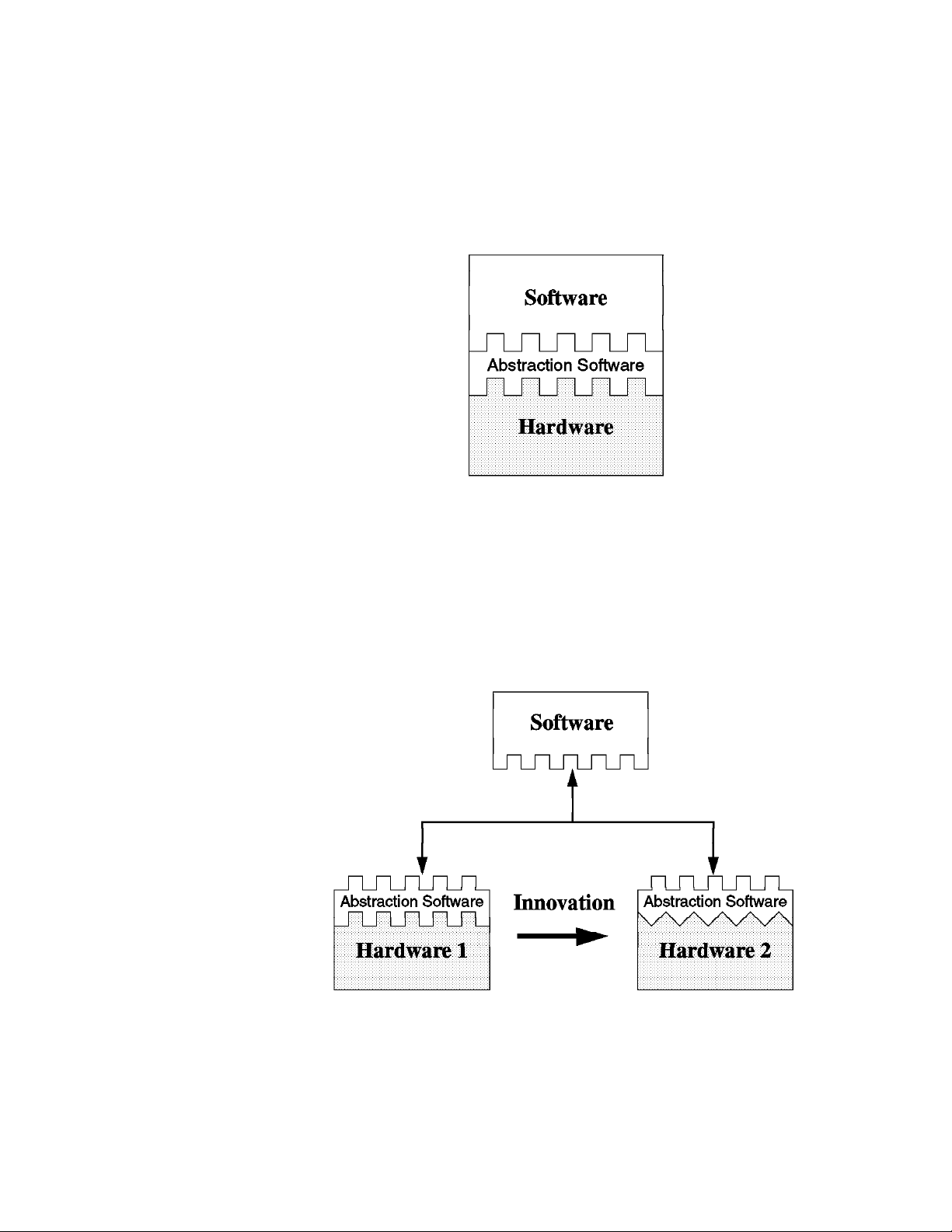
Figure 4. PReP Specification Design Environment
Figure 4 shows, that changing the hardware, for example from hardware level 1 to
hardware level 2, only requires a change in the abstraction layer. No changes are
required in the operating system or in the application itself.
Chapter 1. Introduction 3
Page 28

Independent software vendors (ISV) would like to develop for a large, installed base
of hardware systems and on as few operating system platforms as possible. For
this to happen, an industry standard computer architecture is required. The time
has come to define a new architecture in this area which has the following key
features:
The ability to allow hardware vendors to differentiate
The ability to use industry standard components and interfaces
The ability to support optimization of application performance
Compatible Operating Systems
This type of open system architecture allows hardware system vendors to
develop differentiated, yet compatible, systems. Each system is able to run any
of the compatible operating systems as well as the applications written for these
operating systems and system architecture.
1.2 Introducing the PowerPC Reference Platform Specification
The PowerPC Reference Platform Specification provides a description of the
devices, interfaces and data formats required to design and build a PowerPC-based
industry standard computer system. It is written to create a hardware, which when
coupled with the hardware abstraction software provided by the operating system or
hardware-system vendors, allows the computer industry to build PowerPC systems
which all run the same shrink-wrapped operating systems and the same
shrink-wrapped applications for those operating environments.
It gives system developers the freedom to choose the level of market differentiation
and enhanced features required in a given computer environment without carrying
obsolete interfaces or losing compatibility.
This specification defines the minimum functional requirements for a compliant
PReP implementation. It also provides a list of recommended hardware
subsystems, devices and interfaces.
Operating system vendors may use this specification as a reference to determine
the level of functionality required in a hardware abstraction layer. The specification
shows the hardware subsystems that are likely to change and therefore may need
hardware abstractions.
The PowerPC Reference Platform Specification is written primarily for system
developers. It contains operating-system-specific descriptions and references to
their hardware abstraction approach.
This specification also describes a reference implementation which is a fully
functional PReP system design supporting all operating systems and applications
that are being ported to this reference platform. This reference implementation
provides an example to which system developers can compare and gives them a
better understanding of their own design goals.
This specification supports all 32-bit PowerPC processors and is intended to cover
the following systems:
4 Introduction to PCI-Based RS/6000 Servers
Page 29

Portables
Medialess
Desktop
Workstations
Servers
Because PReP requires machine abstractions, the specification accommodates the
evolution of software and hardware technologies without losing system
compatibility.
The PReP specification covers:
Hardware Configuration
The hardware configuration defines the minimum and recommended
hardware standards and capacities required to be PowerPC Reference
Platform-compliant and compatible with targeted operating
environments.
Architecture
The system architecture defines the minimum and recommended system
attributes required to design a compatible computer system. This
section describes the key hardware and software architecture attributes
and restrictions defined for PReP compliance.
Machine Abstraction
To enable the same operating system to run on different
PReP-compliant platforms, the operating system must be designed to
use
abstraction
Abstraction software concentrates operating system
hardware-dependent code into a collection of code that has well-defined
interfaces with the operating system kernel and may be modified to
meet the hardware interface.
Boot Process
This section describes the boot process, the format and the contents of
boot information, and the state of the system at the end of the boot
process. It also mentions “Open Firmware,” the IEEE standard P1275
for Boot Firmware, as the goal for a PReP-compliant firmware
implementation.
Open Firmware is defined in one of the appendixes included in the
specification.
Reference Implementation
The PReP specification describes a reference implementation of a
PReP-compliant system. This description may be used as a high-level
design for vendors waiting to produce a compatible system, or it may be
used as an example for vendors who want to produce a different
system.
software to interface with the hardware.
Power Management
Power Management is used for saving electronic power. There are two
types of Power Management techniques:
Micro Power Management
This is hardware-managed power control.
Chapter 1. Introduction 5
Page 30

Macro Power Management
This uses system software to control the hardware. Macro Power
Management is, by far, the more powerful technique and thus is the
basis for the PReP Power Management model.
1.3 The PowerPC Microprocessor Common Hardware Reference
Platform (CHRP)
This section introduces the PowerPC Microprocessor Common Hardware
Reference Platform, previously referred to within the industry as Common Hardware
Reference Platform (CHRP), and describes the purposes and the goals of this
platform.
To avoid using the platform's long name, the industry has assigned a nickname to
this specification, PowerPC Platform.
Before talking about the platform itself, we want to give you a brief introduction
about the history, rationale and reasons why this platform had to be developed.
1.3.1 PowerPC Platform - Introduction and History
The PowerPC family of microprocessors, which is being jointly developed by Apple,
IBM and Motorola, is the foundation for an established and rapidly expanding
market for RISC-based systems. Apple Computer has shipped well over one
million Power Macintosh computers since March 1994. IBM has made major
announcements for a full line of PowerPC systems, thus completing its successful
PowerPC-based workstation and server products. Motorola has introduced a broad
range of desktop and server systems. Other companies, such as Bull, Canon and
FirePower, have announced or shipped PowerPC-based systems.
The PowerPC systems shipped by Apple retain many legacy characteristics of
Macintosh hardware and software. The existing PowerPC systems shipped by IBM
and Motorola retain many legacy characteristics of Intel-based PC design. The
operating systems on which the applications run are not compatible with the
different hardware platforms. This incompatibility causes hardware manufacturers
and software developers to have to choose platform families, and this limits the
options available to users.
To correct the problems facing customers and developers, Apple, IBM and Motorola
looked at various ways of combining the two hardware architectures into a common
system architecture. In November 1994, Apple, IBM and Motorola agreed to
develop a specification for a common hardware platform with the purpose of
defining a system which will become the pervasive open industry standard for
single users and on up through to server configurations. Finally, on November 13,
1995, the three companies announced the availability of the PowerPC Platform.
1.3.2 The PowerPC Platform Document
The PowerPC Platform is a set of specifications that defines a unified personal
computer architecture and brings the combined advantages of the Power Macintosh
platform and the standard PC environment to both system vendors and users.
These open specifications will make it easier for system vendors to design
computers capable of running multiple operating systems. Operating systems from
6 Introduction to PCI-Based RS/6000 Servers
Page 31

Apple, IBM, Microsoft, Novell, and SunSoft are planned to support the PowerPC
Platform.
The PowerPC Platform, combined with the superior performance of the PowerPC
RISC microprocessor, will support today's advanced applications and drive the next
generation of applications which address emerging customer requirements for
video, multimedia, virtual reality, speech recognition, 3D graphics, and enhanced
communications. PowerPC Platform-compliant systems will also benefit from the
availability of components designed to industry specifications which can help
reduce costs.
The PowerPC Platform specification is a blueprint for system vendors and
independent hardware vendors. It specifies the kinds of input/output interfaces, bus
standards and other system-level functional elements required to implement a
single, unified architecture around the PowerPC microprocessor. The PowerPC
alliance companies: Apple, IBM and Motorola, are publishing the PowerPC Platform
specifications as part of their initiative to create a superior, industry-wide
RISC-based alternative to the CISC-based X86 offerings. The PowerPC Platform
provides a standard architecture for the next generation of personal computing - an
architecture that is open, multi-OS capable, scalable from portables to
high-performance servers, and free from the limitations of CISC-based
microprocessor architectures, which have had to incorporate RISC-like features to
avoid reaching their performance peak.
The PowerPC Platform, an open, publicly available reference architecture for the
industry, leverages industry standard component designs. System vendors
choosing to implement the PowerPC Platform will benefit not only from the
specifications but also from the reference designs and infrastructure, including
chipsets, peripherals and firmware from leading vendors. Thus, the PowerPC
Platform provides a lower-cost, standard PC foundation for a broad range of
computing systems from multiple system vendors which can help to increase PC
volumes and enables system vendors to differentiate their PowerPC systems.
Additionally, users will benefit from broader access to software applications.
PowerPC Platform Document
The PowerPC Platform document is a superset of the PowerPC Reference
Platform Specification, Version 1.1, the Apple RISC Architecture (Power
Macintosh) and IBM RISC server systems.
1.3.3 PowerPC Platform Goals
The goals of this specification are as follows:
To create an open industry standard to be used for the implementation of
PowerPC-based systems. The architecture document is available to the
industry and can be used by any hardware or software vendor to develop
compliant products.
To allow compatible differentiation through the use of abstracted hardware
interfaces, defined minimum hardware, and extension mechanisms.
To leverage existing and future industry-standard buses and interfaces.
Existing bus architectures have a proven level of performance and functionality.
Established industry-standard interfaces (SCSI, IDE, LocalTalk, Ethernet, and
Chapter 1. Introduction 7
Page 32

so on) and newer bus architectures, interfaces and protocols (PCI, PC Card,
IrDA, and so forth) provide higher levels of performance or utility that are not
achievable by the older standards. The architecture allows platform and
system designers to determine which buses, interfaces and protocols best suit
their target environment.
To provide a flexible address map. Another key attribute of this specification is
the relocatability of devices and subsystems within the PowerPC address
space. Subsystem address information, which defines where I/O devices
reside, is detected by the Open Firmware and passed to the operating systems
in the device tree. The architecture accommodates the use of multiple identical
buses and adapters in the same platform without address conflicts.
To build upon the Open Firmware boot environment defined in IEEE 1275,
IEEE Standard for Boot (Initialization Configuration) Firmware, Core
Requirements and Practices. Currently, the abstraction approach for some
operating systems uses platform description information discovered by a legacy
boot process and passed to the operating system in data structures. With
these systems, operating systems and platforms will migrate to the Open
Firmware boot process and device tree.
To architect the control of power management by different operating systems.
It is important that the combination of hardware and software be allowed to
minimize power consumption through automatic or programmed power-saving
methods. Power management of systems will reduce the operational cost for
the user and reduce the impact of the system on the environment.
To provide an architecture which can evolve as technology changes. The
creators of the architecture invite industry participation in evolving future
versions of it.
To minimize the support cost for multiple operating systems through the
definition of common platform abstraction techniques. Common and compatible
approaches to the abstraction of hardware will reduce the burden on hardware
vendors who produce differentiated machines.
To architect a mechanism for error handling, error reporting and fault isolation.
The architecture provides for the implementation of more robust systems if
desired by the system developers.
PowerPC Platform on the Internet
A
Personal use Only
following Internet site:
http://www.austin.ibm.com/tech/chrp/chrp_book.html
Morgan Kaufmann Publishers provides hardcopies of the specification which
has the number ISBN 1-55860-394-8.
1.3.4 CHRP Certification
Currently, a team is in place to address the CHRP certification process. The
definition of this process is not yet finished; thus the information included below is
preliminary and subject to change.
copy of the PowerPC Platform can be found on the
Requirements for PowerPC Platform (CHRP) systems are established by the AIM
(Apple, IBM, Motorola) Alliance CHRP Specification Committee and defined in the
8 Introduction to PCI-Based RS/6000 Servers
Page 33

PowerPC Microprocessor Common Hardware Reference Platform: A System
Architecture
The AIM Alliance has established the CHRP certification process to accomplish the
following specific goals:
To establish concrete testing criteria for determining the compliance with the
requirements stated in the document titled,
Hardware Reference Platform: A System Architecture
To ensure multiple operating system interchangeability on certified CHRP
computer systems.
To establish a clearly defined set of criteria and procedures for the use of the
CHRP logo.
To make the testing criteria available to the computer industry in an open, fair
and easily accessible manner.
To encourage broad industry participation in the CHRP program through easy
and fair accessibility to testing requirements and procedures.
Any system being certified as a CHRP system will be certified under one of two
classes. These classes are:
Specification.
PowerPC Microprocessor Common
.
CHRP Certified
Intended for systems that will be general user, major market desktop or
Client systems. For this class, a system must be tested and achieve
four approvals from the CHRP Certification Authority. The approvals are
for CHRP hardware systems, the MacOS, Windows NT, and OS/2
operating systems.
CHRP Server Certified
Intended for those systems that will be sold and operated as servers.
For this class, three approvals must be received from the CHRP
Certification Authority. The approvals are for CHRP hardware systems
and for any two of the six CHRP-ported operating systems (AIX,
MacOS, Netware, OS/2, Solaris, and Windows NT).
Chapter 1. Introduction 9
Page 34

10 Introduction to PCI-Based RS/6000 Servers
Page 35

Chapter 2. PCI-Based RS/6000 Server Hardware
The PCI-based RS/6000 server's hardware design is driven by accepted “industry
standards” both formal and de-facto. This means that open, standard interfaces
are used whenever possible, and much of the expansion of the system will be
performed by the end user utilizing standard adapters and controllers.
The design of the PCI-based RS/6000 servers is intended to have much in
common with the PC Server line of products from Boca Raton/Raleigh. The power
and mechanical packaging is the same as that used in the PC Company. In
addition, the electronics partitioning explained in 2.3, “Electronics Partitioning” on
page 19 was chosen so as to allow “processor card agility,” the ability to use either
an Intel x86 or PowerPC architecture processor card.
While the PCI-based RS/6000 servers use a PowerPC Reference Platform (PReP)
compatible basic system architecture, they also build upon the PReP architecture in
order to provide features that are demanded by systems used as servers. These
servers give the customer a basic set of features that make these systems different
from Client systems. These features enhance the performance of the system and
provide a higher level of RAS (Reliability/Availability/Serviceability) than is
commonly found on Client workstations. They include support for future SMP
configurations, standard use of fast L2 caches, large capacity for memory
expansion, higher performance memory subsystems, ECC error- correcting
memory, additional I/O card expansion capability, and higher performance I/O
buses (PCI & ISA). Moreover, the PCI-based RS/6000 servers provide support for
a wide range of devices and features.
2.1 The Hardware Design
The PCI-based RS/6000 servers, packaged in an industry standard tower, are
based on the PowerPC 604 processor.
Figure 5 on page 12 shows the logical block diagram for these servers. The
processor bus runs at 66 MHz and the L2 cache and the Memory Controller are
attached to it. The Memory Controller chip also acts as a PCI Bridge to the primary
PCI bus. Notice that the peripheral units are separated from the PowerPC
processor, the L2 cache and memory through the
PCI Bridge
PCI bus runs at 33 MHz.
The primary PCI is a 32-bit bus. It drives two PCI expansion cards as well as the
secondary PCI bus bridge and the Extended Industry Standard Architecture (EISA)
bus bridge. The system flash EPROM (IPL ROS) is also connected to the primary
PCI bus.
The SCSI-2 Interface Controller and the other PCI slots are connected to the
secondary PCI bus, while the EISA bus allows the connection of on-board ISA
subsystems, such as standard I/O. ISA slots are provided on this bus for a
selection of ISA adapters.
chip. This allows the Processor Local Bus to run at 66 MHz, while the
Processor Memory Controller &
Copyright IBM Corp. 1996 11
Page 36

Figure 5. PCI RS/6000 Entry Server Logical Block Diagram
2.1.1 The PCI Bus Architecture
The Peripheral Component Interconnect (PCI) is a specification standard for
computer bus implementation developed by the PCI Special Interest Group
(PCI-SIG), led by a group of companies including Compaq, Digital, IBM, Intel and
NCR. There are now over 300 companies in the PCI-SIG supporting the
architecture and currently producing PCI products.
The goal was to provide a common system-board bus that could be used in
personal computers, from laptops to servers. It was envisioned as a local system
board bus that would serve as a common design point, supporting different system
processors as the various processors evolved over time. This is much like
operating systems which have defined Application Binary Interfaces (ABIs) so that
applications need not change with each generation of the operating system. The
PCI Local Bus would serve as a common hardware interface that would not change
with different versions of microprocessors.
The group defined PCI to support the high-performance basic system I/O devices,
such as the graphics adapter, hardfile controller and/or LAN adapter. In the original
definition, these would be mounted on the planar and would communicate through
the PCI bus. Current I/O buses (ISA, EISA and Micro Channel) would be used to
attach pluggable features to configure the system for the desired use. The first
release of PCI Specification was made available in June of 1992.
The PCI Special Interest Group (SIG) soon realized that the PCI bus needed the
capabilty to support connectors. For example, display controller evolution doesn't
necessarily match planar development; so providing for an upgrade of the display
controller became a requirement. The next release of the PCI Specification
12 Introduction to PCI-Based RS/6000 Servers
Page 37

(Version 2.0 in April of 1993) included upgrade capability through expansion
connectors.
According to PCI Specification Version 2.0, the PCI bus operates on 32- or 64-bits
of data at a clock speed of 33 MHz. This yields a local bus performance of 132
MB/sec for 32-bit transfers and 264 MB/sec for 64-bit transfers. The next PCI
Specification (Version 2.1) is expected to include a definition of 66 MHz PCI
capability, increasing local bus performance to 528 MB/sec for 64-bit transfers.
Though each PCI bus is restricted to a maximum of four slots, the addition of
multiple PCI-to-PCI bridges allows multiple PCI buses to be included in a system as
a means for providing additional slots when needed. Each PCI Bridge adds
another PCI bus, which in turn can handle up to four slots each.
2.1.1.1 PCI Features and Benefits
The PCI bus architecture has many advantages involving the following:
High data transfer speed
Processor independence
Cross-platform compatibility
Plug and Play
Investment protection
High Data Transfer Speed
The high-speed data transfer is implemented by the following functions:
Buffering and asynchronous data transfer
The PCI chip can support the processing and buffering of data and commands
sent from the processor or from the peripherals in case the peripheral or the
processor is not yet ready to receive the information.
Burst mode transfer
Variable length linear or toggle mode bursting for both reads and writes
improves write-dependant graphics performance.
Caching
To reduce the access time, the PCI bus architecture supports caching of data
which is frequently used.
DMA
The Direct Memory Access (DMA) function is used to enable peripheral units to
read from and write to memory without sending a memory request to the
processor. This function is very useful for peripherals that need to receive
large amounts of data, such as video adapters, hard disks and network
adapters.
Processor Independence
Processor independence allows manufacturers to implement PCI buses on any
computer. Any PCI-compliant peripheral will work on any PCI-compliant bus
implementation.
Cross-Platform Compatibility
Chapter 2. PCI-Based RS/6000 Server Hardware 13
Page 38

The key to cross-platform compatibility is processor independence. Until PCI,
different systems used different buses, such as ISA, EISA, NuBus, and so forth.
Now, different systems can use one bus.
Multi-bus Support
An important aspect to PCI-based system architecture is support for multiple PCI
buses, operating transparently to existing software.
Plug and Play
PCI peripherals, following the PCI standard, load the appropriate set of installation,
configuration and booting information to the host CPU without user intervention.
This provides a greater ease of use for the system integrator or end-user.
Investment protection
The PCI bus is designed for 64-bit addressing support.
2.1.2 The ISA BUS Architecture
The Industry Standard Architecture (ISA) is the most widely used system bus in the
PC industry. Originally, there were no official definition or standards for it. Later
on, its specifications were defined by the Institute of Electrical and Electronics
Engineers (IEEE) standards group.
The ISA bus, if implemented, allows a transfer rate of up to 8.3 MB/s. Transfers
over the ISA bus are synchronized around 8 MHz, and they usually take a
minimum of two cycles of the bus clock to perform a data transfer. Since the data
path of an ISA bus is 16 bits wide, up to two bytes may be transferred during each
transaction.
Since ISA is the most widely bus architecture used in the PC industry, it makes
sense to provide users with the possibility to use hardware peripherals they already
use with other systems, rather than having to expend additional money for these
peripherals.
Moreover, supporting the ISA bus architecture, the system-provider has access to a
wide spectrum of adapters and devices already available in the marketplace and
does not have to wait for adapters to be built for a specific system bus. The
provider has to ensure that the device driver for the specific operating system is
also available.
The problem when connecting the processor to the ISA bus directly is that the
processor's speed has to be reduced to match the slow ISA bus speed; thus the
systems cannot take advantage of a fast processor.
Table 1 shows the bus specification for different architectures and compares them
to the PowerPC processor's speed.
14 Introduction to PCI-Based RS/6000 Servers
Page 39

Table 1. PowerPC and Bus Specification
Specification PowerPC PCI ISA(8) ISA(16) EISA
Processor Speed
(601-604)
Databus 64 64 8 16 16/32
Address Bus 32 64 20 24 24/32
Bus Clock 66 MHz 33 MHz 4.7 MHz 8.3 MHz 8.3 MHZ
Interrupts - 4 6 11 11
DMA Channel - busmaster 3 7 7
The solution to the problem is to use the PCI local bus as the primary system bus
and the ISA bus as an expansion bus. This way, the system can take advantage
of the high-speed data transfer provided by the PCI bus when communicating with
the processor and memory. On the other side, through the PCI-ISA Bridge, the bus
clock can be reduced to match the ISA bus requirements.
66-132 - - - -
2.2 The Hardware Main Components
The PCI-based RS/6000 servers include the following main hardware components:
Processor Subsystem
L2 Cache
Memory Controller and PCI Bridge
System Memory
Primary PCI Bus
Secondary PCI Bus
EISA Bus
X-bus
No Power Management Controller
Note that the currently available PCI-based RS/6000 servers (E20 and F30) do
not include a power-management controller.
2.2.1 The Processor Subsystem
The PCI-based RS/6000 servers feature the PowerPC 604 microprocessor. The
superscalar multiprocessor-enabled chip issues up to four instructions in parallel
every clock cycle. Its three-stage, double-precision floating point unit provides
tremendous performance capabilities that were previously available only through
expensive add-on hardware.
Figure 6 on page 16 shows the PowerPC 604 microprocessor architecture which is
defined by the following specifications:
PowerPC 604 microprocessor running at:
– 100 MHz on RS/6000 Model E20
– 133 MHz on RS/6000 Model F30
Chapter 2. PCI-Based RS/6000 Server Hardware 15
Page 40

Up to 66 MHz bus clock
Superscalar design with integrated integer, floating-point and branch units
16 KB four-way set-associative instruction cache
16 KB four-way set-associative data cache
64-bit memory interface with 32-bit addressing
Virtual memory support for up to four petabytes (252)
Real memory support for up to four gigabytes
Support for Big-Endian and Little-Endian modes
Nap power management mode
Figure 6. PowerPC 604 Microprocessor Logical Block Diagram
2.2.2 The L2 Cache
The L2 cache subsystem is directly attached to the processor bus which runs at 66
MHz. It is managed by a Write-Through Look-Aside controller which interfaces to
two Cache Tag RAM modules and eight synchronous Strip Cylindrical Random
Access Memory (SCRAM) modules to form a 512 KB L2 cache assembly.
16 Introduction to PCI-Based RS/6000 Servers
Page 41

The cache controller supports disable, inhibit and invalidate functions in addition to
the expected L2 memory caching operations.
2.2.3 The Memory Controller and PCI Bridge
The Memory Controller chip is directly attached to the processor bus and acts as a
PCI Bridge to the primary PCI bus as well.
It issues two different bus interfaces:
The CPU bus interface that runs at 66 MHz
The PCI bus interface that runs at 33 MHz
The memory controller supports address and data-bus parity generation and
checking. It provides support for Big- and Little-Endian modes and for 604 the
MESI protocol which is used as cache synchronization logic in SMP systems.
The PCI Bridge provides a low-latency path through which the processor may
directly access PCI devices mapped anywhere in the memory or I/O address
spaces. It also provides a high-bandwidth path giving the PCI bus Masters direct
access to main memory.
2.2.4 The System Memory
The PCI-based RS/6000 servers use JEDEC-Standard 168 pin, 5 volt, 70 nSec,
single bank, eight-byte parity or ECC memory DIMMs (Dual Inline Memory
Modules). By using DIMMs, you get the benefit of a 64-bit wide memory without
having to use paired or quad memory modules. In this way, you can upgrade
system memory using one DIMM module at a time, while maintaining maximum
flexibility and simplicity.
Either parity or ECC (Error Checking and Correcting) DIMMs may be used to
provide maximum flexibility. Even if parity DIMMs are used, the system implements
an ECC memory subsystem.
The Error Checking and Correcting (ECC) feature supported by the system memory
subsystem is a fault-tolerant one. ECC corrects single-bit memory failures that can
be induced temporarily by environment noises or permanently by hardware
problems. Using ECC will prevent the majority of memory failures from impacting
the system operation. ECC also provides double-bit memory error detection which
protects data integrity in the rare event of a double-bit failure.
The memory subsystem provides eight DIMM sockets for memory expansion that
are placed on the I/O Motherboard.
2.2.5 The Primary PCI Bus
The primary PCI bus is generated by the Memory Controller/Host Bridge chip. This
32-bit PCI bus is fully PCI 2.0 Specification compatible. It drives expansion card
slots as well as the secondary PCI bus bridge and the EISA bus bridge. In
addition, the MPIC (Multi-Processor Interrupt Controller) resides on the primary PCI
bus, as shown on Figure 5 on page 12.
Chapter 2. PCI-Based RS/6000 Server Hardware 17
Page 42

2.2.6 The Secondary PCI Bus
The secondary PCI bus is generated through the use of a PCI-to-PCI bridge chip.
This component regenerates a second PCI bus interface from the primary bus and
uses it to drive additional PCI expansion card slots. The PCI-to-PCI bridge handles
all the arbitration for devices on the secondary bus. Due to arbitration restrictions
on the primary PCI bus, the SCSI interface resides on this secondary PCI bus.
Secondary bus latency adds, on average, two PCI clocks (60 nSec at 33 MHz) of
overhead on the first cycle of all SCSI operations. For this reason, PIO (Parallel
I/O) operations will incur this overhead for each cycle, while burst data transfers will
incur the latency for the first cycle of the block transfer only.
2.2.7 The EISA Bus
The EISA bus is generated through a bridge from the primary PCI bus. The bridge
drives several expansion card slots. Since EISA is a proper super-set of the ISA
bus specification, all ISA adapters are completely supported in these EISA
expansion card slots.
Note that 8-bit “belly hanger” ISA cards are not supported in either EISA or
full-specification ISA card connectors. These special cards require unique
8-bit-only slots that are not supported by the PCI-based RS/6000 servers.
2.2.8 The X-Bus
The EISA bus contains the integrated native I/O support chip. This chip
incorporates a floppy disk controller, two full function UARTs (Universal
Asynchronous Receiver/Transmitters, support for RS232 drivers) and a
bi-directional parallel port.
The X-Bus is an 8-bit ISA subset bus used to attach several common subsystems
to the PCI-based RS/6000 servers. The following components are attached to this
bus:
The Keyboard/Mouse controller, which is common to all Power Personal
Systems products
Real-Time Clock and Non-volatile RAM
The functions of Real-Time Clock (RTC) and Non-volatile RAM (NVRAM) are
integrated into a single component in the PCI-based RS/6000 servers. This
component also supplies the logic required to perform the function of powering
the system on at a designed time. The component is operated from a lithium
battery on the board so that all time-keeping functions continue to work while
system power is turned off.
Mini-Support Processor (IòC Controller)
The Mini-Support Processor is a minicontroller that is imbedded into the I/O
planar of the PCI-based RS/6000 servers. It allows the PowerPC processor
access to VPD, Operator panels and other IòC bus attached devices.
18 Introduction to PCI-Based RS/6000 Servers
Page 43

2.3 Electronics Partitioning
The system electronics are divided into two cards for packaging. One card
contains the processor and its support electronics, master clock generation,
memory controller and IPL microcode. The other card is considerably larger and
contains the native I/O subsystems, memory modules and I/O expansion slots.
Figure 7 shows how the components are split across the two boards in the system.
Figure 7. PCI-Based RS/6000 Server's Electronics Partitioning
The division of logic across the two cards was carefully chosen so that it would split
the electronics along industry standard open interfaces only. Furthermore,
packaging the processor and memory controller on the same card allows much
greater flexibility in the design for future upgrade cards. As new processor and
memory controllers are developed, they may be offered to customers as
performance enhancements upgrades while protecting the customer investment in
memory, I/O and packaging.
The electronics on the processor card comprise the core of the PowerPC
Reference Platform architecture. The processor card's interface boundary
separates the PReP architecture from the mostly PC architecture of the I/O
Motherboard. So this “processor card agility” allows other processor cards to be
designed and used with the same I/O Motherboard and mechanical package.
Four industry standard interfaces are used to attach the processor to the I/O
subsystem:
A generic 72-bit, non-interleaved memory DIMM interface to connect the
memory controller on the processor card to the DRAM modules
A 32-bit PCI bus running at up to 33 MHz for I/O subsystem attachment
Chapter 2. PCI-Based RS/6000 Server Hardware 19
Page 44

The X-bus interface
An IòC bus which supports RAS monitoring features on processor card
2.4 RS/6000 Model E20 Product Description
The RS/6000 Model E20 is the first member of the PCI-based RS/6000 family of
servers to become available. It is designed to allow for system growth in memory,
disk and media devices as the customer's needs grow. The E20 server is a
low-priced, high performance commercial server. By combining AIX Version 4.1.4
reliability and functionality with industry standard bus architectures, the E20 offers
exceptional value for multiuser applications.
Figure 8. RISC System/6000 Model 7024-E20
The 7024-E20 offers fast processing and outstanding performance capabilities due
to PowerPC 604 technology running at 100 MHz. It can process an estimated 735
transactions per minute (tpm). Due to these powerful features, this entry level
workgroup server can be a great choice for managing department, stand-alone or
distributed-computing environments. It works as a great server to the Model 43P
Series workstations as well as other workstations.
The E20 has been designed for customer set up. The modular processor card
makes it convenient to replace the microprocessor card as new PowerPC
technology emerges. Eight media bays and eight expansion slots provide enough
room to grow. The I/O slots support the emerging high-performance PCI standard
as well as the traditional ISA bus architecture.
The E20 is packaged in an 8 x 8 (eight I/O slots, eight-disk/media bay), allows up
to a maximum of 13.2 GB of internal storage capacity and features a flexible I/O
subsystem of 5 PCI, 2 ISA and one shared slots.
20 Introduction to PCI-Based RS/6000 Servers
Page 45

2.4.1 Standard Features
In this section, we describe the standard features of the RS/6000 Model E20 and
point out their most important characteristics.
Processor Subsystem
The PCI-based RS/6000 Model E20 server features the PowerPC 604
microprocessor at 100 MHz. The processor includes an L1 cache composed by a
16 KB instruction and a 16 KB data cache.
The L2 cache is integrated onto the CPU board and is always present in the base
system. The synchronous L2 cache is 512 KB in size.
Memory
The Model E20 comes standard with a 16 MB ECC memory DIMM in one memory
slot. The system memory can be expanded up to 512 MB. For this reason, eight
memory sockets are provided which accept 8 MB, 16 MB, 32 MB or 64 MB 168-pin
DIMMs. As DIMM sockets are used, a single memory slot can be added each time
with no need to add them in pairs.
No Select Feature for Memory
The standard 16 MB memory DIMM cannot be selected for memory upgrades in
initial machine order.
Either parity or ECC memory DIMMs can be used and mixed together, providing
great flexibility. This allows the customer to easily upgrade the processor cards
without taking care which kind of memory is installed.
Bays
The system, as shown in Figure 9 on page 22, contains eight bays, three of which
accommodate the following standard devices:
3.5-inch diskette drive bay
It accommodates the standard 1.44 MB diskette drive.
5.25-inch CD-ROM drive bay
It accommodates the standard Quad-speed 680 MB CD-ROM drive with the
convenience of loading a CD without a caddy. The tray loading mechanism
provides support for 12 and 8 cm disks.
The CD-ROM supports standard and XA formats. Its multi-session capability
supports Photo-CD applications.
5.25-inch disk drive bay
It accommodates the standard 1080 MB disk drive that can be upgraded in the
initial machine order to a 1.1 GB or 2.2 GB disk.
The five empty bays can accommodate 3.5-inch or 5.25-inch drives such as disk,
CD-ROM, tape drives or other removable-media drives. Although these bays are
1.6-inch high, they can be used with 1.0-inch high devices only (see 2.4.3,
“RS/6000 Model E20 Limitations” on page 31).
Chapter 2. PCI-Based RS/6000 Server Hardware 21
Page 46

Figure 9. RS/6000 Model E20 Front View
Slots
Eight slots are available which can accommodate the following adapters types:
Five slots for PCI adapters
Two slots for ISA adapters
One shared slot that can accommodate either a PCI or an ISA adapter
Integrated SCSI-2 adapter
The system comes standard with an integrated PCI-based internal SCSI-2 fast/wide
controller that can be used for internal SCSI-2 devices only. You can have all
narrow, all fast/wide or a combination of both SCSI-2 types on the internal SCSI-2
bus.
Standard I/O ports
The system provides the following standard I/O ports:
Keyboard port - The IBM Enhanced Keyboard, an optional feature on the Model
E20
Mouse port - Port provided to support an optional three-button mouse
Two 9-pin D-shell serial connectors for external RS232 access
One 25-pin parallel port that maintains complete compatibility with ISA, EISA
and microchannel parallel ports
22 Introduction to PCI-Based RS/6000 Servers
Page 47

2.4.2 Supported Optional Features
In this section, we consider as “optional features” the internal optional devices,
external adapters and external subsystems that can be configured on the RS/6000
Model E20.
2.4.2.1 Internal Disk Drives
Six internal SCSI-2 disk drives can be accommodated in the internal bays of the
system. The disk drives that can be installed and configured are described in
Table 2.
Only disk drives with a 1-inch height (half-height) are supported for internal use.
Disk drives with 1.6-inch height are not supported as they may result in overheating
of the system.
Table 2. Optional Disk Drives on Model E20
Formatted Capacity 1080 MB 1.1 GB 2.2 GB
Feature Number # 2397 # 3032 # 3033
SCSI Bus Rate MB/sec 10 20 20
Average Seek Time ms 12.0 8.5 8.5
RPM 5400 7200 7200
Average Latency ms 5.6 4.17 4.17
Interface SCSI-2 SCSI-2
Data Width 8-bit 16-bit 16-bit
Note: Maximum Internal Disk Drives: 6
F/W
SCSI-2
F/W
2.4.2.2 Internal Tape Drives
Currently, the only tape drive that can be installed in an internal bay of the system
is the 4GB/8GB 4mm Internal Tape Drive.
A maximum of two internal tape drives can be installed. Due to overheating
problems that could lead to data errors, they have to be mounted in bay number 6
and 8, leaving bay number 7 empty. If one tape drive has to be installed, we
suggest mounting it in bay number 8.
Table 3. Optional Tape Drives on Model E20
Tape Capacity 4.0 GB 8.0 GB
Feature Number # 6142 # 6142
Cartridge IBM 4mm DDS IBM 4mm DDS
Data Compression No Yes
Max Effective Transfer Rate 400 KB/sec 800 KB/sec
Interface SCSI-2 (8 bit) SCSI-2 (8 bit)
Bays 1 half-height 1 half-height
Note: Maximum Internal Tape Drives: 2
Chapter 2. PCI-Based RS/6000 Server Hardware 23
Page 48

2.4.2.3 Internal CD-ROM Drives
A maximum of two internal CD-ROM drives can be installed in the E20 system.
The CD-ROM provides four-speed performance with the convenience of loading
CDs without a caddy.
Table 4. Optional CD-ROM drive on Model E20
CD-ROM Capacity 600 MB
Feature Number # 2616
Interface SCSI-2 (8 bit)
Interface Speed (average) 600 KB/sec
Interface Speed (burst) 5.0 MB/sec
Bays 1 half-height
Note: Maximum CD-ROM Drives: 2
2.4.2.4 Graphics Adapter
Currently, the only graphics adapter supported by the RS/6000 Model E20 is the
IBM PCI S15 Graphics Adapter (feature #2657). Moreover, only one PCI S15
adapter is officially supported in the system.
Note: We successfully tested two S15 graphics adapters in a system. Refer to
5.6.4, “Multiple Adapter Support” on page 96 for more information.
The IBM S15 Adapter is a high-performance Video RAM (VRAM) based PCI
graphics adapter with integrated video co-processor for use as a premium graphics
solution. The adapter comes in a 2 MB fixed version. It supports the standard
15-pin D-shell (DB-15).
Table 5 on page 25 shows the supported monitors.
24 Introduction to PCI-Based RS/6000 Servers
Page 49

Table 5. Supported Monitors on Model E20
Description Model Feature
Code
P50 UV-N MPR-II Color Monitor 6553-503 3612 13.6"
P50 UV-S MPR-II Color Monitor 6553-504 - 13.6"
P50 TCO-92 Color Monitor 6553-523 - 13.6"
P70 Color Monitor 6554-603 3613 15.9"
P70 UV-S MPR-II Color Monitor 6554-604 - 15.9"
P200 Color Monitor 6555-703 3614 19.1"
P200 UV-S MPR-II Color Monitor 6555-704 - 19.1"
P201 Color Monitor 6555-803 3615 19.1"
IBM 14V Color Monitor 6324/001 - 13.0"
IBM 15V Color Monitor 6325/001 - 13.7"
IBM 17V Color Monitor 6327/001 - 15.8"
IBM 21P Color Monitor 9521/001 - 19.1"
IBM 14P Color Monitor 9524/001 - 13.0"
IBM 15P Color Monitor 9525/001 - 13.7"
IBM 17P Color Monitor 9527/001 - 15.4"
G40 Monitor 6542-G40 - 13"
G41 Monitor 6542-G41 - 13"
G50 Monitor 6543-G41 - 13.6"
G70 Monitor 6544-G50 - 15.9"
G200 Monitor 6545-G20 - 19.1"
Note: Maximum graphics adapters: 1
Screen
Size
2.4.2.5 PCI SCSI-2 Adapters
The following two PCI SCSI adapters are supported:
PCI SCSI-2 Single Ended Fast/Wide Adapter (feature #2408)
PCI SCSI-2 Differential Fast/Wide Adapter (feature #2409)
PCI SCSI-2 Single Ended Fast/Wide Adapter
The adapter can burst data to devices on the SCSI bus at 20 MB/sec.
It has both an internal and an external connector which are physically connected to
the same SCSI bus. The adapter external connector is a shielded 68-conductor
connector consisting of two rows of 34 female contacts.
The adapter supports both 8-bit and 16-bit devices.
The maximum number of addressable IDs enabled by the adapter is 15, but due to
cabling restrictions, the actual total number of supported devices attached to the
internal and external connector may be less.
The adapter occupies one PCI bus slot, and a maximum of six adapters can be
installed in the RS/6000 Model E20.
Chapter 2. PCI-Based RS/6000 Server Hardware 25
Page 50

PCI SCSI-2 Differential Fast/Wide Adapter
The adapter can burst data to devices on the SCSI bus at 20 MB/sec.
It has a single connector for attachment of external differential devices. It is a
shielded 68-conductor connector consisting of two rows of 34 female contacts.
Both 8-bit and 16-bit device attachments are supported, but intermixing 8-bit and
16-bit devices is not supported.
The maximum number of addressable IDs enabled by the adapter is 15, but due to
cabling restrictions, the actual total number of supported devices attached to the
internal and external connector may be less.
The adapter occupies one PCI bus slot, and a maximum of six adapters can be
installed in the Model E20.
The following table shows the maximum number of both internal and external
devices that can be attached to a SCSI-2 adapter together with related cables. By
“Multi-device,” we mean an external enclosure that may contain more than one
SCSI device.
Table 6. SCSI Adapter Connections on Model E20
Adapter Maximum number of devices Cables Feature Code
Feature
Code
Native 7 0 0 Not
2408 4 4 0 2442 2111,
2408 0 4 0 Not
2408 0 0 1 Not
2409 0 25 meter cable maximum Not
Note: Maximum SCSI adapters: 6
Internal External Internal External
Single MultiDevice
required
allowed
allowed
allowed
2.4.2.6 Communication Adapters
The following communication adapters are supported:
Not
allowed
2113,
2115, 2117
2111,
2113,
2115, 2117
2111,
2113,
2115, 2117
2112,
2114, 2116
Auto LANstreamer Token-Ring PCI Adapter
PCI Ethernet Adapters
ISA X.25 Adapter
ISA 4-Port Multiprotocol Communications Controller
ISA 8-Port Asynchronous Controller EIA-232
ISA 128-Port Asynchronous Controller
26 Introduction to PCI-Based RS/6000 Servers
Page 51

Auto LANstreamer Token-Ring PCI Adapter (feature #2979)
It is designed to allow a PCI-based RS/6000 server to attach to 4 Mbps or 16 Mbp
s token-ring local area networks. The adapter automatically selects the correct
token-ring speed (4-16 Mbps). It is compatible with all IBM PS/2 Token-Ring
adapters; no new cables or network components are required.
The adapter has one connector, RJ-45. The RJ-45 connector is used to attach to
Unshielded Twisted Pair (UTP) cabling. A 10-inch conversion cable is included
with the adapter to attach to Shielded Twisted Pair (STP) cabling.
The following are the main characteristics of this adapter:
4 Mbps or 16 Mbps speed (automatically set)
Compatible with IEEE 802.5 specifications
Full Duplex enabled
Occupies one PCI slot
Maximum number of adapters: 6
PCI Ethernet Adapters
Two types of PCI Ethernet adapters are supported depending on the different kind
of connections you need for your Local Area Network.
PCI ETHERNET BNC/RJ-45 ADAPTER (FEATURE #2985)
It supports connections to 10Base2 networks via BNC connectors and to
10BaseT networks via RJ-45 connectors.
PCI ETHERNET AUI/RJ-45 ADAPTER (FEATURE #2987)
It contains a 15-pin DIX Ethernet connector, and it supports 10BaseT networks
via RJ-45 connectors.
Both adapters provide 10 Mbps Ethernet connectivity. They adhere to the PCI
Revision 2.0 and IEEE 802.3 standards. They feature low-cost, high performance
32-bit cards. Each adapter includes three LEDs to provide status to the card's
operation and each includes auto-sense of the media connection. The controller
chip on the card contains integrated DMA buffer management for CPU and bus
utilization and look-ahead packet processing which allows protocol analysis to begin
before the end of the frame is received. It requires one PCI slot, and a maximum
of six adapters can be installed on the Model E20.
ISA X.25 Adapter (feature #2961)
The X.25 Interface Co-Processor Adapter ISA bus provides for the attachment to
synchronous data networks at speeds up to 64 Kbps.
It is important to remember that the IBM AIXLINK/X.25 LPP for AIX is a software
requirement to provide connection to X.25 packet-switched networks. This adapter
provides a single port connection to X.25 networks that will accommodate one of
the three selectable features:
EIA-232D/V.24 interface up to 19.2 Kbps
V.35 interface up to 56/64 Kbps
Chapter 2. PCI-Based RS/6000 Server Hardware 27
Page 52

X.21 (not switched) up to 64 Kbps
Each feature is selected by the cable, which can be ordered in 3m (9 foot) or 6m
(18 foot) length. These are the main characteristics for this adapter:
Code resident on the adapter off-loads low-level X.25 tasks from the system
processor
512 KB RAM for buffering
Synchronous protocols can be supported
Automatic recognition of the selected interface cable
Capacity of concurrent support up to 250 virtual channels
Requires one ISA slot
Maximum of three adapters of this type can be installed
Installation and configuration of this adapter is not automatically made by AIX;
proper operations must be followed by the system manager. The DIP switches on
the adapter must be set correctly before configuring the adapter to the AIX
operating system. 6.7, “X.25 Interface Co-Processor ISA Adapter (FC 2961)” on
page 120 explains how to install and configure this adapter.
ISA 4-Port Multiprotocol Communication Controller (feature #2701)
This adapter supports the attachment to wide area networks at speeds up to 64
Kbps. This adapter consists of a base card and daughter card. The two cards are
physically connected and require a single ISA bus card slot.
This adapter can support four different physical interfaces by using a IBM 4-Port
Multiprotocol Interface Cable (feature #2705). This cable is actually a breakout box
featuring four ports that support EIA-232, EIA-422A, V.35, and X.21 physical
interfaces.
The main characteristics for this adapter are:
80C186 @ 10 MHz processor
1 MB RAM for data buffering
Synchronous protocols
EIA232, EIA422A, V.35, and X.21 physical interfaces supported
Requires one ISA slot
Maximum of three adapters of this type can be installed
Installation and configuration of this adapter is not automatically made by AIX;
proper operations must be followed by the system manager. DIP switches on the
adapter must be set correctly before configuring the adapter to the AIX operating
system. 6.6, “4-Port Multi-Protocol ISA Adapter (FC 2701)” on page 115 explains
how to install and configure this adapter.
ISA 8-Port Asynchronous Adapter (feature #2931)
This adapter is used to connect up to eight EIA-232 asynchronous serial devices
(terminals, modem, printers, and so on). This feature provides both the adapter
28 Introduction to PCI-Based RS/6000 Servers
Page 53

card and an 8-port DB25 connector box, composed of eight asynchronous ports
from a single I/O card slot.
The main characteristics for this adapter are:
Data rates up to 115.2 Kbps per port
Fully buffered transmit and receive data
Single 78-pin connector for connection to 8-port DB25 connector box
Supports the following interface signals:TxD, RxD, RTS, CTS, DSR, DCD, DTR
and RI
Maximum EIA-232 distance supported is 62 meters (200 feet)
Requires one ISA slot
Maximum of three adapters of this type can be installed
Installation and configuration of this adapter is not automatically made by AIX;
proper operations must be followed by the system manager. DIP switches on the
adapter must be set correctly before configuring the adapter to the AIX operating
system. 6.4, “8-Port EIA-232 Asynchronous ISA Adapter (FC 2931)” on page 108
explains how to install and configure this adapter.
ISA 128-Port Asynchronous Adapter (feature #2933)
This adapter provides for a high concentration of asynchronous lines from a single
ISA bus slot. Two synchronous channels link the adapter to a maximum of eight
16-Port Remote Asynchronous Nodes (RAN) (feature #8130 in USA & Canada
only; feature #8134 World Trade). Each channel can support up to four 16-Port
RANs.
One 4.5 meter cable (feature #8131) is available to connect the adapter to the first
RAN on each channel. Additional RAN modules may be connected to each
channel in a “daisy chain” configuration, using either the 4.5 meter (15 foot) cable
(feature #8131) or the 23 cm (9 inch) cable (feature #8132). Customer-supplied
cables may also be substituted.
These are the main characteristics for this adapter:
Data rates up to 57.6 Kbps per port
Support to 128 ports per adapter
Supports the following interface signals:TxD, RxD, RTS, CTS, DSR, DCD, DTR,
and RI
Maximum EIA-232 distance supported is 62 meters (200 feet)
Requires one ISA slot
Maximum of three adapters of this type can be installed
Installation and configuration of this adapter is not automatically made by AIX;
proper operations must be followed by the system manager. DIP switches on the
adapter must be set correctly before configuring the adapter to the AIX operating
system. 6.5, “128-Port EIA-232 Asynchronous ISA Adapter (FC 2933)” on
page 111 explains how to install and configure this adapter.
Chapter 2. PCI-Based RS/6000 Server Hardware 29
Page 54

2.4.2.7 External Subsystems
The following is a list of the external subsystems which are officially supported in
the RS/6000 Model E20.
Disk Subsystems
7131 Model 105 SCSI Multi-Storage Tower
7137 RAID Disk Array Subsystem Model 412, 413, 414
7203 Model 001 External Portable Disk
Tape Drive Subsystem
7207 Model 012 - 1.2 GB 1/4 Inch Tape drive
7206 Model 005 - 4 GB 4mm Tape Drive
7208 Model 011 - 5 GB 8mm Tape Drive
Tape Libraries
7332 Model 005 - 4mm Library
7331 Model 205 - 8mm Library
LAN Subsystems
7318 Model P10 Serial Communication Network Server
7318 Model S20 Serial Communication Network Server
Optical Drives/Libraries
7210 Model 010 External CD-ROM Drive
3995 Models A63, 063, 163 Optical Library Dataservers
ASCII Terminals
IBM 3151, 3153, 3161, 3162, 3163, 3164
DEC VT100, VT220, VT320, VT330
WYSE 30, 50, 60,350
Modems
IBM 5841, 5853, 5865
Hayes compatibles
Racal-Vadic compatibles
Printer/Plotters
Any AIX 4.1.4 supported serial, parallel or LAN-attached printer/plotter.
30 Introduction to PCI-Based RS/6000 Servers
Page 55

2.4.3 RS/6000 Model E20 Limitations
When planning or implementing an RS/6000 Model E20, give special consideration
to the following limitations, which are also listed in the announcement letter for this
product.
Internal Disk Drives
Only internal disk drives with a 1-inch height (half-height) are supported. Disk
drives with 1.6-inch height (4.5 GB disks) are not supported. Installation of any
full-height internal disk may result in overheating the system, and data consistency
is not guaranteed
Internal Tape Drives
The 4 GB/8 GB 4mm internal tape drive may be mounted in bay number 8 only.
This insures adequate air flow, as required for proper operation. A second tape
drive may be installed in bay number 6 if bay number 7 remains empty. Mounting
in another bay may cause overheating and lead to data errors.
No 8mm internal tape drive can be installed in the RS/6000 Model E20.
Graphics Adapter
There can be a maximum of one graphics adapter installed on the system.
SCSI Adapters
The limitations regarding SCSI adapters and the number of attachable devices are
shown in Table 6 on page 26.
2.5 RS/6000 Model F30 Product Description
The RS/6000 Model F30 significantly enhances the IBM PCI-based RS/6000 family
of entry servers. The Model F30 is a workgroup server that is well suited for the
emerging markets of distributed computing and interoperability. Like the RS/6000
Model E20, the F30 can be used with existing AIX 4.1.4 applications where industry
common PCI and ISA standards are required.
The Model 7025-F30 is a powerful and expandable server designed to combine the
following attributes:
Outstanding performance of PowerPC technology - 820 estimated transactions
per minute (tpm)
System expandability supporting 10 I/O slots and 22 media/disk bays.
Reliability characteristics of commercial servers
Industry common I/O and memory architectures
Packaging characteristics of small departmental servers
It offers more performance, more I/O slots and more bays than the Model E20 as
well as offering enhanced server RAS characteristics, such as ECC memory.
The F30 is packaged in a 10 x 22 (10 I/O slots, 22 media/disk bays) floor-standing
tower which is attractive, compact and quiet. It includes a modular disk subsystem
Chapter 2. PCI-Based RS/6000 Server Hardware 31
Page 56

that allows fast, easy addition and replacement of drives, also called “Hot-swap
subsystem” (see Chapter 3, “Hot-Swap Subsystem” on page 41 for information
about this subsystem).
This system allows up to a maximum of 40 GB of internal storage capacity and
features a flexible I/O subsystem of three PCI, three ISA and four shared slots.
The most important RS/6000 Model F30 RAS attributes are the following:
ECC memory
Integrated service processor
Hot-swap disk drives
Concurrent diagnostics
Due to all these features, the Model F30 is the ideal server for applications that
require large memory (up to 512 MB) combined with large disk capacity.
2.5.1 Standard Features
In this section, we describe the standard features of the RS/6000 Model F30s and
point out their most important characteristics.
Processor Subsystem
The PCI-based RS/6000 Model F30 server features the PowerPC 604
microprocessor at 133 MHz. The processor includes an L1 cache composed of a
16 KB instruction and a 16 KB data cache.
The L2 cache is integrated onto the CPU board and is always present in the base
system. The L2 cache is 512 KB in size.
Memory
The Model F30 comes standard with a 32 MB ECC memory DIMM in one memory
slot. The system memory can be expanded up to 512 MB. For this reason, eight
memory sockets are provided which accept 16 MB, 32 MB or 64 MB 168-pin
DIMMs. As DIMM sockets are used, a single memory slot can be added each time
with no need to add them in pairs.
No Select Feature for Memory
The standard 32 MB memory DIMM cannot be selected for memory upgrades in
the initial order.
Either parity or ECC memory DIMMs can be used and mixed together, providing
great flexibility. This allows the customer to easily upgrade the processor cards
without worrying about which kind of memory is installed.
Bays
The system contains ten standard bays and twelve optional hot-swap disk drive
bays, as shown in Figure 10 on page 33.
32 Introduction to PCI-Based RS/6000 Servers
Page 57

Figure 10. RS/6000 Model F30 Bays
Standard bays are composed of four media and six hot-swap disk bays which
accommodate the following drives:
Two of the media bays accommodate the following standard devices:
– 3.5-inch diskette drive bay that accommodates a standard 1.44 MB diskette
drive
– 5.25-inch CD-ROM drive bay that accommodates a Quad-speed 680 MB
CD-ROM drive with the convenience of loading a CD without a caddy. The
tray loading mechanism provides support for 12cm and 8cm disks.
The additional two media bays are empty on standard configuration. They
measure 5.25 inches wide by 1.6 inches high, and they can accommodate
3.25- and 5.25-inch drives, such as CD-ROM, tape drives and hard disks.
One hot-swap disk bay accommodates a standard 2.2 GB disk drive. This disk
can be upgraded to an 4.5 GB disk drive in the initial order.
The additional available five hot-swap disk bays are empty in system standard
configurations.
Slots
Ten slots are available which can accommodate the following adapters types:
Three slots for PCI adapters
Three slots for ISA adapters
Four slots that can accommodate either a PCI or an ISA adapter
Integrated SCSI-2 Adapter
Chapter 2. PCI-Based RS/6000 Server Hardware 33
Page 58

The system comes standard with an integrated PCI-based internal SCSI-2 fast/wide
adapter that can be used only for internal, single ended, either fast/wide, narrow or
both, SCSI-2 devices (maximum of seven).
Standard I/O Ports
The system provides the following standard I/O ports:
Keyboard port. The IBM Enhanced Keyboard is an optional feature on the
Model F30.
Mouse port. A port is provided to support an optional three-button mouse.
Two 9-pin D-shell serial connectors for external RS232 access.
One 25-pin parallel port that maintains complete compatibility with ISA, EISA
and microchannel parallel ports.
Power Supply
The system is provided with a 694-watt power supply unit with dual voltage to
enable large disk drive configurations. The power supply assembly consists of two
power supplies, a 474 watt supply and a 220 watt supply. Each supply can be
replaced separately.
2.5.2 Supported Optional Features
In this section, we consider as “optional features” the internal optional devices,
external adapters and external subsystems that can be configured on RS/6000
Model F30.
Most of the external adapters and subsystems supported by system F30 are
supported by system E20 as well. For this reason, we refer to the E20 external
adapters and subsystems described in the previous paragraphs when it is
necessary.
2.5.2.1 Internal Disk Drives
Internal SCSI-2 F/W disk drives in varied capacities in the industry standard
3.5-inch form factor can be installed on the system. Internal disk drives available
have 1.1 GB, 2.2 GB and 4.5 GB capacities, and their main characteristics are
described in Table 7 on page 35.
These disk drives are hot-swappable. They can be accommodated in any of the
hot-swap disk bays in the system using a hot-swap disk driver carrier. The “carrier”
is a tray providing an interface between the standard SCSI-2 disk drive and a
backplane connector that enables disks to be hot-swappable.
Both 1-inch height (half-height) and 1.6-inch (full-height) disk drives are supported,
but while half-height disks require only one hot-swappable bay, the full-height ones
occupy two. For this reason, the maximum number of full-height disk drives (4.5
GB disks) that can be installed is 9 (two bays for each drive), while the maximum
number of half-height disk drives is 18 (one bay for each drive).
34 Introduction to PCI-Based RS/6000 Servers
Page 59

Table 7. Optional Disk Drives on Model F30
Formatted Capacity 1.1 GB 2.2 GB 4.5 GB
Feature number # 3082 # 3083 # 3084
SCSI Bus Rate MB/sec 20 20 20
Average Seek Time ms 7.2 7.8 8.3
RPM 7200 7200 7200
Avarage Latency ms 4.17 4.17 4.17
Interface SCSI-2
F/W
Data Width 16-bit 16-bit 16-bit
Swappable Bays 1 1 2
Note: Maximum Internal Half-height Disk Drives: 18
SCSI-2
F/W
SCSI-2
F/W
2.5.2.2 Internal Tape Drives
Both 4mm and 8mm Internal Tape Drives can be installed in an internal,
non-hot-swappable media bay. Unlike the Model E20, there are no limitations on
the bay where the internal tape is to be installed.
Table 8 shows the main characteristics of internal tape drives.
Table 8. Optional Tape Drives on Model F30
Tape Capacity 4.0 GB 8.0 GB 5.0 GB 10.0 GB
Feature number # 6142 # 6142 # 6147 # 6147
Cartridge IBM 4mm
DDS
Data Compression No Yes No Yes
Max Effective Transfer
Rate
Interface SCSI-2 (8
Note: Maximum Internal Tape Drives: 2
400
KB/sec
bit)
IBM 4mm
DDS
800
KB/sec
SCSI-2 (8
bit)
IBM 8mm
DDS
500
KB/sec
SCSI-2 (8
bit)
IBM 8mm
DDS
1000
KB/sec
SCSI-2 (8
bit)
2.5.2.3 Internal CD-ROM Drives
The CD-ROM provides four-speed performance with the convenience of loading
CDs without a caddy. There are no restrictions on bay positions apart from the
standard CD-ROM drive mounted in bay number A2. Table 4 on page 24 shows
the main CD-ROM features.
2.5.2.4 Graphics Adapter
Currently, the only graphics adapter supported by Model F30 is the IBM PCI S15
Graphics Adapter (feature #2657). Moreover, only two PCI S15 adapters can be
installed in the system. Refer to Table 5 on page 25 to look for the display
monitors that the Model F30 supports. They are the same ones supported by
Model E20.
Chapter 2. PCI-Based RS/6000 Server Hardware 35
Page 60

2.5.2.5 PCI SCSI-2 Adapters
The following two PCI SCSI adapters are supported:
PCI SCSI-2 Single Ended Fast/Wide Adapter (feature #2408)
PCI SCSI-2 Differential Fast/Wide Adapter (feature #2409)
Each adapter occupies one PCI slot, and a maximum of seven adapters can be
installed in the Model F30. Refer to 2.4.2.5, “PCI SCSI-2 Adapters” on page 25 for
technical information about these SCSI-2 Adapters.
As described in 2.5.1, “Standard Features” on page 32, the RS/6000 Model F30
features four media bays, six standard and 12 optional half-height hot-swappable
disk bays. To add six half-height hot-swappable disk bays to the system, additional
hardware is required. This hardware consists of a backplane, a power cable, a PCI
SCSI-2 F/W Adapter, a SCSI cable, and mounting hardware. This kit can be
ordered as a hardware feature named
6-Pack #3 Kit (feature #6422)
, depending on which optional hot-swappable bays
are going to be installed.
Table 9 shows the maximum number of both internal and external devices that can
be attached to a SCSI-2 adapter and related cables for the RS/6000 Model F30.
SCSI 6-Pack #2 Kit (feature #6421)
or
SCSI
Table 9. SCSI Adapter Connections on Model F30
Adapter Maximum number of devices Cables Feature Code
Feature
Code
Native 3 media +
2408 6 hot-swap
2408 0 0 1 Not
2409 0 25 meter cable maximum Not
Note: Maximum SCSI adapters: 6
Internal External Internal External
Single MultiDevice
0 0 Not
6 hot-swap
disks
4 0 2448,
disks
required
6421, 6422
allowed
allowed
2.5.2.6 Communication Adapters
The following communication adapters are supported:
Auto LANstreamer Token-Ring PCI Adapter
Not
allowed
2111,
2113,
2115, 2117
2111,
2113,
2115, 2117
2112,
2114, 2116
PCI Ethernet Adapters
– PCI Ethernet BNC/RJ-45 Adapter
– PCI Ethernet AUI/RJ-45 Adapter
ISA X.25 Adapter
ISA 4-Port Multiprotocol Communications Controller
ISA 8-Port Asynchronous Controller EIA-232
36 Introduction to PCI-Based RS/6000 Servers
Page 61

ISA 128-Port Asynchronous Controller
These are the same adapters that can be installed and configured in the RS/6000
Model E20. Refer to 2.4.2.6, “Communication Adapters” on page 26 for technical
information about these PCI and ISA adapters.
2.5.2.7 External Subsystems
Here, we list the external subsystems that are officially supported in the RS/6000
Model F30.
Disk Subsystems
7131 Model 105 SCSI Multi-Storage Tower
7137 RAID Disk Array Subsystem Model 412, 413, 414
7203 Model 001 External Portable Disk
Tape Drive Subsystem
7207 Model 012 - 1.2 GB 1/4 Inch Tape drive
7206 Model 005 - 4 GB 4mm Tape Drive
7208 Model 011 - 5 GB 8mm Tape Drive
Tape Libraries
7332 Model 005 - 4mm Library
7331 Model 205 - 8mm Library
LAN Subsystems
7318 Model P10 Serial Communication Network Server
7318 Model S20 Serial Communication Network Server
Optical Drives/Libraries
7210 Model 010 External CD-ROM Drive
7209 Model 002 1.19 GB Read/Write Optical Disk Drive
3995 Models A63, 063, 163 Optical Library Dataservers
ASCII Terminals
IBM 3151, 3153, 3161, 3162, 3163, 3164
DEC VT100, VT220, VT320, VT330
WYSE 30, 50, 60,350
Modems
IBM 5841, 5853, 5865
Hayes compatibles
Racal-Vadic compatibles
Printer/Plotters
Any AIX 4.1.4 supported serial, parallel or LAN-attached printer/plotter.
Chapter 2. PCI-Based RS/6000 Server Hardware 37
Page 62

2.5.3 RS/6000 Model F30 Limitations
When planning or implementing an RS/6000 Model E20, give special consideration
to the following limitations, which are also listed in the announcement letter for this
product.
Internal Disk Drives
4.5 GB Disk drives (1.6 inch height) require two hot-swappable bays.
Graphics Adapter
There can be a maximum of two graphics adapters installed in the system.
SCSI Adapters
There are also SCSI limitations, depending on the adapter, as shown in Table 9 on
page 36.
2.6 Hardware Requirements
Both models require either an ASCII terminal with a serial attachment cable or a
graphics display attached to the graphics adapter for initial set up. Any of them
must be available for service. If an ASCII terminal is used, it
serial port S1.
must
be attached to
If no graphics adapter is installed, the system firmware will send boot messages to
serial port S1. If a graphics adapter is installed, the boot messages will only be
directed to the graphics adapter and not to the serial port, S1.
The officially supported boot devices for these systems are CD-ROM, internal or
external hard disk or network devices using Ethernet or token-ring adapters. Also,
internal or external
2.7 Performance Positioning
Values shown here are the results of development-level systems. All performances
data for Model E20 and Model F30 was obtained in a specific environment and is
presented "as is" for illustrative purpose only. While these values should be
indicative of general available systems, no warranties or guarantees are stated or
implied by IBM. IBM recommends application-oriented testing for performance
predictions and offers the following reported benchmarks only as an initial indicator.
Additional information on these tests is available from IBM Local Branch Office or
IBM Authorized Reseller.
tape drives
can be used as bootable devices.
38 Introduction to PCI-Based RS/6000 Servers
Page 63

Table 10. PCI-based RS/6000 Comparison Performance Table
Description C20 43P E20 F30
Processor PowerPC 604 604 604 604
Clock (MHz) 120 133 100 133
L2 Cache (MB) 1 ñ 0.5 0.5 0.5
SPECint95 - 4.72 3.67 4.74
SPECfp95 - 3.76 3.13 3.49
SPECint_base95 3.85 ò 4.55 3.43 4.56
SPECfp_base95 3.50 ò 3.59 3.06 3.34
LINPACK DP (MFLOPS) 22.7 ò 27.8 23.5 23.1
LINPACK TPP (MFLOPS) 62.7 ò 67.5 62.3 69.0
tpm est. (02/96) 620 ò 400 735 850 ó
Notes
1. Optional L2 Cache
2. Reflects use of largest optional L2 cache
3. tpm with 960 MB (Statement of Direction)
AIX Version 4 was used with each of these benchmarks. IBM C Set++ for AIX
Version 3.1.2 and AIX XL FORTRAN Version 3.2.2 are the compilers used in these
tests. The preprocessors used in the tests include KAP 2.5. for FORTRAN and
KAP/C 1.4.2 from Kuck & Associates, VAST-2X.03h28 from Pacific Sierra
Research. The preprocessors were purchased separately from these vendors.
SPECint95: Result is the geometric mean of eight tests that comprise the
CINT95 benchmark suite. All of these are written in C language.
SPECint_base95: It is the result of the same tests in CINT95 with a maximum of
four compilers flags that must be used in all eight tests.
SPECint_base_rate95: Geometric average of the eight SPEC rates from the
SPEC integer tests (CINT95) with the restrictive compiler options.
SPECfp95: Result is the geometric mean of ten tests that comprise the CFP95
benchmark suite. All of these are written in FORTRAN language.
SPECfp_base95: It is the result of the same tests in CFP95 with a maximum of
four compilers flags that must be used in all ten tests.
SPECfp_base_rate95: Geometric average of the eight SPEC rates from the
SPEC floating-point tests (CFP95) with the restrictive compiler options.
LINPACK DP: Double precision, n=100 results with AIX XL FORTRAN compiler
with optimization. Units are megaflops (MFLOPS)
LINPACK TPP: Toward Peak Performance, n=1000 results with AIX XL
FORTRAN compiler with optimization. Units are megaflops (MFLOPS)
tpm reflects IBM's estimate of complex commercial transactions per minute.
Chapter 2. PCI-Based RS/6000 Server Hardware 39
Page 64

2.7.1 SPEC95 Software Benchmark
SPEC95 is a forward step in the performance measurement of the core of a
system. It covers the CPU, caches, memory, and compiler. The programs and
datasets which make up the suite cannot "fit" into cache, making the benchmark
more representative of real workloads. SPEC has also standardized the compiler
settings so that the results for "base" measurements are more comparable between
suppliers.
SPEC95 is a software benchmark product produced by the Standard Performance
Evaluation Corp. (SPEC), a non-profit group of computer vendors, systems
integrators, universities, research organizations, publishers and consultants
throughout the world. It was designed to provide measures of performance for
comparing compute-intensive workloads on different computer systems.
SPEC95 contains two suites of benchmarks:
CINT95 for measuring and comparing compute-intensive integer performance
CFP95 for measuring and comparing compute-intensive floating point
performance
The two groups of programs are referred to as component-level benchmark suites
as they test the core of the system, the CPU, caches, memory, and compiler, but
not
the I/O sub-system.
One of the goals of SPEC95 is increased portability; the current offering from SPEC
is for UNIX only although the member companies have indicated that the
benchmark programs are portable to various flavors of UNIX, Windows NT and
Open VMS.
SPEC95 introduces a new reference platform against which other systems are
measured, changing from the out-dated VAX 11/780 to a SPARCstation 10/40 with
64MB memory but without Level 2 cache. This is more representative of the types
of systems being sold today, but it is also a machine that will beat few, if any, of
the machines being benchmarked.
The rules have also changed; each benchmark must be run a minimum of three
times to get a valid result, with the median time for all runs being used as the
benchmark time.
The
SPEC base metrics
reported results and have set guidelines for compilation (for example, the same 4
flags must be used in the same order for all benchmarks). The non-base metrics
(for example, SPECint95) are optional and have less strict requirements (for
example, different compiler options may be used on each benchmark).
(for example, SPECint_base95) are required for all
There are several different ways to measure computer performance. One way is to
measure how fast the computer completes a single task; this is a speed measure.
Another way is to measure how many tasks a computer can accomplish in a certain
amount of time; this is called a throughput, capacity or rate measure. The SPEC
speed metrics (for example, SPECint95) are used for comparing the ability of a
computer to complete single tasks. The
SPECint_rate95) measure the throughput or rate of a machine carrying out a
number of tasks.
SPEC rate metrics
(for example,
40 Introduction to PCI-Based RS/6000 Servers
Page 65

Chapter 3. Hot-Swap Subsystem
The F30 is the first PCI-based RS/6000 server to provide hot-swap disk capability.
The hot-swap subsystem allows the addition or removal of disk drives without
powering-down the system. The hot-swap subsystem also allows applications to
keep running which do not use the disk that has to be replaced or removed.
The hot-swap subsystem uses special, hot-swappable disk carriers that allow you
to easily plug and unplug disks in the system. The connectors, however, have an
estimated lifespan of 500 insertions and removals. If the user expects to insert and
remove a drive daily, it may begin to fail intermittently resulting in a hot-swap
carrier, backplane or drive having to be replaced. This subsystem, therefore, is not
intended to be used as a removable disk subsystem.
The hot-swap subsystem uses a common hardware design and components that
will be used not only in the RS/6000 division but also in several other IBM divisions.
This chapter describes the F30 Hot-Swap subsystem and the features of AIX which
can take of advantage of this capability.
3.1 Components
The hot-swap subsystem hardware is divided into three major components. These
components are shown in Figure 11 and are described below.
Figure 11. Components
Backplane
The backplane card provides connectors and electronics support for up to six
half-height or three full-height 3.5 inch 8 or 16 bit disk drives. The backplane
card includes power management and hot-plug sense logic.
Copyright IBM Corp. 1996 41
Page 66

Hot-Swap Disk Drive Carrier
The hot-swap SCSI disk drive carrier is a tray with built-in SCSI connectors that
provide the interface between an industry standard SCSI 16-bit or 8-bit disk
drive and the 80-pin backplane connector.
The carrier includes two LEDs. One of the LEDs is used to indicate the status
of the disk drive, and the other one is the power LED indicator for the carrier.
Carriers are available for two drive types: narrow (half-height) and wide
(full-height). The narrow carrier has a 50-pin drive connector. The wide carrier
has a 68-pin drive connector. Both narrow and wide carriers have the same
connector at the rear of the hot-swappable carrier. The different carriers,
therefore, can be installed into the same backplane card.
Disk Drive
The following IBM disk drives have been tested within this environment:
– 1080 MB SCSI-2 disk drive:
– 1.1 GB SCSI-2 Fast/Wide disk drive
– 2.2 GB SCSI-2 Fast/Wide disk drive
The hot-swap subsystem additionally requires a power source and a SCSI-2
Fast/Wide SE adapter. The first backplane is connected to the first power supply
and to the integrated SCSI-2 Fast/Wide. Additional backplanes will be connected
to an additional SCSI-2 Fast/Wide PCI adapter and obtain their power from the
second power supply.
3.1.1 Backplanes
The F30 can accommodate up to three backplanes each of which can
accommodate a maximum of six hot-swappable disks. The first backplane is
installed in bank C (as shown in Figure 12 on page 43) and is supplied with the
F30 as standard.
– 4.5 GB SCSI-2 Fast/Wide disk drive
42 Introduction to PCI-Based RS/6000 Servers
Page 67

Figure 12. Installing Hot-Swap
The second (feature #6421) and the third (feature #6422) backplanes are installed
in banks D and E, respectively. The features, #6421 and #6422, contain all of the
necessary hardware to completely enable up to six hot-swap disks to be installed in
the machine: the backplane, the power cable, the SCSI controller, the SCSI cable,
and mounting hardware.
The F30 default configuration is to control bank C's hot-swap disks and the
removable media devices (CD-ROM and so forth) with the integrated SCSI-2
Fast/Wide controller. For improved performance, an optional PCI SCSI-2 SE
Fast/Wide adapter (feature #2408 or equivalent) can be installed to provide an
independent SCSI bus for Bank C's disk drives. Feature #2446 provides the
necessary cable to control bank C's disks from this optional SCSI adapter.
3.1.2 Hot-Swap Bays and Banks
For a disk drive to be installed in one of the hot-swappable bays, the disk must use
a hot-swappable carrier.
Each hot-swap bank contains six bays and can accommodate three full-height disk
drives/carriers or six half-height disk drives/carriers. A combination of half- and
full-height disk drives/carriers is possible.
Hot-swap bays are numbered from 1 to 6 from left to right. SCSI IDs ranging from
8 to 13 are assigned automatically from left to right. When disks are installed in the
carriers, their SCSI ID jumpers have to be removed. The hot-swap bay SCSI ID
numbering is shown in Figure 13 on page 44.
Chapter 3. Hot-Swap Subsystem 43
Page 68

Figure 13. Front Bays
3.2 Installation
The requirements for installing hot-swap disk drives are not the same for all three
banks. A general requirement is that each hot-swap bank requires a separate
SCSI-2 adapter. In the case of the first bank, bank C in Figure 12 on page 43, it
uses the integrated SCSI-2 controller. Banks D and E require the installation of
one additional backplane each. These additional backplanes use the second power
supply which is provided with the F30.
3.2.1 Accessing the Hot-Swap Banks
To access the hot-swap banks, you must first remove the front cover of your
machine as shown in Figure 14 on page 45. To do this, refer to the chapter
"Installing Options" in the F30 User's Guide; then look at the section titled
"Removing the Front Covers Only." In the same order as this section describes,
you should:
1. Open and remove the door.
2. Release the front cover latch.
3. Unlock the keylock.
4. Remove the front cover.
44 Introduction to PCI-Based RS/6000 Servers
Page 69

.
Figure 14. Removing the Front Panel
This will provide you access to the hot-swap banks. If you only have one
backplane installed you will be able to add or remove up to six disks.
3.2.2 Installing Drives in Bank C
The backplane for bank C comes installed in the system. The SCSI IDs are
automatically assigned by the backplane for each bank. Therefore, no jumpers are
required on the drives. If your disk drive has SCSI ID jumpers set, you must
remove them. Refer to the disk drive booklet provided with the system or with your
disk drive. Attaching SCSI address jumpers on the drive rather than using the
automatic ID supplied by the backplane is not advised.
Each drive you plan to install in bank C must have the hot-swap carrier attached. It
is recommended that you install the hard disk in the next unused position.
3.2.3 Installing Drives in Bank D
To install drives in bank D, you must first install a backplane in the back of the
bank and an SCSI-2 Fast/Wide adapter in a spare PCI expansion slot. The
installation procedure is as follows:
1. Install a backplane in the bank.
2. Install an additional PCI SCSI-2 Fast/Wide adapter.
3. Connect the SCSI adapter to the backplane.
4. Connect the additional power supply to the backplane.
5. Install the hot-swap drive as you would for bank C.
Chapter 3. Hot-Swap Subsystem 45
Page 70

3.2.4 Installing Drives in Bank E
Installation of drives in bank E is exactly the same as the procedure for installing
drives in bank D.
3.2.5 Disk Carriers
The disk carriers have two lights which enable you to determine the status of the
drive. Figure 15 shows a diagram of the lights and the spin down button, and
Table 11 explains their meanings.
Figure 15. Disk Drive Light
Table 11. Status Lights
Light or Button Status Definition
Amber On Drive spinning
Off Drive not spinning
Green On Power On
Off Power Off
Blinking Power Off/Drive identify
Spin down Depressed Spin down drive and remove power
During normal operation of AIX, both of the lights on the disk carrier will be on. If a
drive is removed from the ODM, for example, by using:
rmdev -d -l hdiskx
the drive will spin down, and the amber light will go out.
46 Introduction to PCI-Based RS/6000 Servers
Page 71

3.3 Using the Hot-Swap Subsystem
Having the hot-swap subsystem is very useful. As previously mentioned, it allows
you to add, remove or replace disk drives without shutting down and powering-off
your system. There are, however, three levels at which you can use the hot-swap
subsystem.
First, you can use the hot-swap subsystem to simply add and remove disk drives
from the system. You can buy and add new drives with ease, and these can be
quickly configured into your system without affecting the users. You can also
export volume groups and remove the drives to put into other hot-swap systems, or
you could remove a disk from a volume group and use the disk as an extra disk for
another system.
Second, there is replacement usage. You may only have one system with the
hot-swap capability and will only remove drives if they become faulty. In this
scenario, you can replace the drive without powering-off and shutting down the
system. To enable the removal of the drive, the administrator will tell AIX that the
disk is to be removed from the system. If the data on the disk can still be
accessed, the administrator can migrate the contents of the disk to another one or
back up the data on the disk. The disk will then be replaced, and using a backup
of the data on this disk or by migrating the data back, the disk will be re-added to
the system, and any data which was originally on the disk will be restored. In this
scenario, where the data was not migrated, users who were using data on the drive
will be affected. The users will be unable to access their data until a replacement
drive has been fitted and the data restored.
The third usage of the hot-swap subsystem is mirroring, effectively giving the
subsystem RAID 0. Failures happen infrequently, but when the failures do happen,
they can cause havoc with your data. Using mirroring with the hot-swap subsystem
allows the system to carry on using data contained on a disk even if that disk fails
since it will be able to use a mirror. If a disk fails, the disk can be replaced and the
new disk added to the system. A mirror can then be rebuilt without affecting AIX,
the applications or the users. The subject of mirroring is discussed later in this
chapter.
3.3.1 Adding a New Drive to a Live System
When you install a new drive in the hot-swap subsystem, the amber light in the
carrier will flash and then go out. This indicates that the drive has been identified
and is not spinning. At this point, AIX does not know that the drive is present in the
system. To tell AIX that you have added a new drive, you can use SMIT or type:
cfgmgr
from the command line. Running this command will cause AIX to find the drive and
spin it up. You will see the amber light come on at this point and will hear the
sound of the drive spinning up. Using the lspv command, you will be able to see
your new drive added. f the drive contains a volume group, you access it from your
system by running:
importvg -y VGname hdiskx
Otherwise, you can add the disk to an existing volume group by using extendvg or
create a new volume group by using smit mkvg.
Chapter 3. Hot-Swap Subsystem 47
Page 72

3.3.2 Removing a Drive from a Live System
To be able to remove a hot-swap drive from the system without causing problems,
you will have to tell AIX that you are removing the drive.
3.3.2.1 Removing a Disk From an Existing Volume Group
If you want to physically remove the disk and it belongs to an existing volume
group, you would either remove the logical volumes which are present on the disk
(you can find out which logical volumes are present on a disk by using the lspv -l
hdiskx command), or migrate the physical partitions from the disk to other disks in
the same volume group. To remove a disk from an existing volume group, you can
use the following procedure:
1. Unmount all the filesystems on the disk if you are removing the logical volumes
on the disk.
2. Remove all data from the drive by either removing the logical volumes or by
migrating the partitions on the disk to another disk in the same volume group.
If you are removing the logical volumes, you may wish to back up the data prior
to removal.
3. Remove the drive from the volume group:
reducevg VGname hdiskx
4. Remove the device from the ODM:
rmdev -d -l hdiskx
When you run the rmdev command, the amber light on the drive will switch off.
If you run lspv, you will see that the disk is no longer defined to the system.
5. Physically remove the drive from the system.
3.3.2.2 Removing a Drive with its Own Volume Group
To remove a drive which has its own volume group, you can use the following
procedure:
1. Back up any data that you require from the volume group.
2. Unmount all the filesystems on the disk.
3. Varyoff the volume group by issuing:
varyoffvg VGname
4. Export the volume group by issuing:
exportvg VGname
5. Remove the device from the ODM by issuing:
rmdev -d -l hdiskx
6. Physically remove the device from the system.
The disk can easily be re-added to the system, and the volume group can be
accessed using the importvg command.
48 Introduction to PCI-Based RS/6000 Servers
Page 73

3.3.3 Replacing a Previously Defined Drive
If you add a disk drive which was already configured to the system and was
removed using the procedures described above, then you can simply add the new
drive as described in 3.3.1, “Adding a New Drive to a Live System” on page 47.
3.3.3.1 Replacing a Previously Defined Drive into the Same Bay
If a drive was physically removed without first being logically removed from the
operating system, then AIX may have problems. If there were no writes to the disk
after the removal of the disk, then there may be no requirement to run any
commands. If a write occurred after or during the removal of the drive and the
drive has been re-added, then you should perform the following:
1. Unmount all filesystems on the disk.
2. fsck -y filesystems on the disk.
3. Remount the filesystems on the disk.
3.3.3.2 Replacing a Previously Defined Drive into a Different Bay
If you replace a drive into a different bay from the one from which it was removed,
the one configured to the system by running the cfgmgr command, and you didn't
remove the device from the ODM before physically removing the device, then you
will have to clear up the ODM because there will be a duplicate entry for the drive.
The following shows a scenario where there were three disks in the system and
two volume groups on two separate disks. The disk belonging to testvg was
physically removed without telling AIX.
Running the lspv command shows the three disks:
lspv
hdisk a641877c rootvg
hdisk1 ba645b testvg
hdisk2 a627464 None
hdisk1 was removed from the system before telling AIX. The disk was replaced
into a different bay than it was removed from. The cfgmgr command was run to
configure the disk back into the system, and now lspv shows:
lspv
hdisk a641877c rootvg
hdisk1 ba645b testvg
hdisk2 a627464 None
hdisk3 ba645b testvg
There are now two entries for the testvg volume group, both with the same
physical volume identifier. This is incorrect and can be cleared up by performing
the following:
1. Umount all filesystems in the testvg volume group.
2.varyoffvg testvg
3.exportvg testvg
At this point, you may get the following error which you can ignore:
516-24 /usr/sbin/lqueryvg: Unable to open physical volume.
Either PV was not configured or could not be opened. Run
diagnostics.
Chapter 3. Hot-Swap Subsystem 49
Page 74

Running lspv now shows:
lspv
hdisk a641877c rootvg
hdisk1 ba645b None
hdisk2 a627464 None
hdisk3 ba645b None
4. rmdev -d -l hdisk1
5. rmdev -d -l hdisk3
6.cfgmgr
Running lspv now shows the correct disks:
lspv
hdisk a641877c rootvg
hdisk1 ba645b None
hdisk2 a627464 None
7. importvg -y testvg hdisk1
8. Mount all the filesystems. You may have to run fsck -y on the filesystems first
if they were written to while the disk was removed.
3.3.4 Mirroring
Mirroring disks has been discussed at great detail in many publications and in
InfoExplorer. Here, we will explain an outline of the process you will need to take
to use mirroring. Mirroring will take maximum advantage of the hot-swap
subsystem.
The hot-swap subsystem will mean that AIX will have to be explicitly told about the
removal and addition of disks. In a normal AIX environment the system would have
been shut down and powered-off. The system would then recognize the removal or
addition of disks.
3.3.4.1 Removing and Adding a Mirrored Disk
If you want to remove a disk which is a mirror of other disks in its volume group,
you can either remove the logical volume's copies which are on the disk and follow
the procedure outlined in 3.3.2.1, “Removing a Disk From an Existing Volume
Group” on page 48, or you can remove the disk without telling AIX. If you choose
to remove the disk without telling AIX, you should perform the following when you
re-add the disk:
1. Unmount all the filesystems which are mirrored on the disk.
2. Change the state of the disk in the volume group to active:
chpv -v -r hdiskx
chpv -v -a hdiskx
3. Synchronize all the partitions on the disk from their mirrors:
syncvg -v VGname
4. Remount all the filesystems which are mirrored on the disk.
This will ensure that AIX correctly knows about the disk being re-added and that all
the partitions are correctly synchronized.
50 Introduction to PCI-Based RS/6000 Servers
Page 75

If the disk is part of the root volume group and the filesystems which are on the
disk can't be unmounted, then you can either wait for a reboot of the system or
remove the disk from the volume group, and then re-add the disk by performing the
following:
1. Remove all the mirrored copies from the mirrored disk (for example, if we had a
logical volume called lv00, there were a total of two copies of the logical
volume and the disk which was removed was hdiskx):
rmlvcopy lv 1 hdiskx
2. Reduce the rootvg to remove the disk:
reducevg rootvg hdiskx
3. Remove the device from the ODM:
rmdev -d -l hdiskx
4. Insert the new drive.
5. Configure it to the system:
cfgmgr
6. Extend the root volume group to this disk:
extendvg rootvg hdiskx
7. Recreate the mirrors on the disk, for example:
mklvcopy lv 2 hdiskx
Chapter 3. Hot-Swap Subsystem 51
Page 76

52 Introduction to PCI-Based RS/6000 Servers
Page 77

Chapter 4. Boot Support and Firmware
The PCI RS/6000 Entry Server systems are based on the PowerPC Reference
Platform Specification (PReP); thus, in contrast to the microchannel-based RS/6000
systems systems, their hardware is not bound to a specific operating system.
In order to separate the hardware from the software, an abstraction layer, defined
in PReP, is required. The abstraction layer is called Software ROS (Read-Only
Storage) and includes the following two components:
BTAS (Boot Time Abstraction Software) Abstracts the hardware that a platform's
boot program (for example, firmware) uses at boot time. It also
abstracts the hardware that the operating system loader uses to load an
operating system.
RTAS (Run-Time Abstraction Software) A collection of data and software that
abstracts hardware from the operating system kernel
For more information on the PReP-specific abstraction layer, refer to the
AIX V4 on PCI-Based RS/6000 Workstations
Reference Platform Specification.
Figure 16. Boot Structure on PCI-Based RS/6000 Systems and Microchannel-Based
RS/6000 Systems
redbook, or to the PowerPC
Managing
Figure 16 shows the components involved in booting a PCI-based RS/6000 system
compared to the microchannel-based RS/6000 systems.
Since on the microchannel-based RS/6000 systems the only operating system
supported is AIX, the firmware (also called system ROS on those machines) builds
the IPL control block required by the AIX boot image using the structure defined by
AIX.
On PCI-based RS/6000 systems, the firmware initializes the hardware in a generic
way to allow any PReP-compatible operating system to boot on the system. The
hardware initialization data is passed to the abstraction layer software via residual
Copyright IBM Corp. 1996 53
Page 78

data. In the case of AIX, the abstraction layer builds the required IPL control block
before the AIX boot image is loaded.
In the first part of this chapter, we will explain the components involved in the boot
process:
Boot record
Firmware
Software ROS
NVRAM
Boot image
Then, we will describe the boot process performed by the firmware, and finally we
will give an introduction to the System Management Services (SMS) programs.
4.1 Boot Record
On microchannel-based RS/6000 systems machines, the entire disk is dedicated to
the AIX operating system. Block 0 of the disk is expected to contain the
boot-record.
Figure 17. Hardfile Layout on Microchannel-Based RS/6000 Systems
The hardfile layout on PCI-based RS/6000 systems is designed to allow
transportable media between various processor types (for example, Intel and
PowerPC 60x) the hardfile layout is similar as now found on a system running DOS
or OS/2. It implements the concept of disk partitions as specified in the PReP
Specification. Following this architecture, the AIX disk image would reside in one of
those partitions, as shown in Figure 18.
Figure 18. Hardfile Layout on PReP Specification
54 Introduction to PCI-Based RS/6000 Servers
Page 79

Different partitions could hold different operating systems or different versions of
AIX. The user could be able to choose the operating system to boot, as in
“dualboot” on OS/2 and DOS.
The problem with this implementation is that both the Master boot record and the
AIX boot record are required to start on disk block 0. To satisfy this requirement,
the boot record on PCI-based RS/6000 systems is a combination of both, as shown
in Figure 19.
Figure 19. Hardfile Layout on Microchannel-Based RS/6000 Systems
Note
Partitioned disks are not supported in the current release of AIX. Currently, AIX
requires all disks used by AIX to be dedicated disks.
4.2 Boot Components Specifically for AIX 4 on PCI-Based RS/6000
Systems
The firmware on microchannel-based RS/6000 systems is sophisticated enough to:
Find the boot device
Build the IPL control Block required by the AIX boot image
Load the AIX boot image from the boot device
Pass control to the boot image
On PCI-based RS/6000 systems, however, the firmware is simple and generic,
independent of the operating system; therefore it does not build the IPL control
block for AIX, but:
Finds the boot device
Locates the operating system bootstrap code
Passes control to the bootstrap code
regardless which operating system is booting.
In order to create the IPL control block and perform the initialization required by the
AIX boot image, a new, intermediary software component has to be added to the
boot process on PCI-based RS/6000 systems, the Software ROS.
The boot process on PCI-based RS/6000 systems includes the following three
major components:
Chapter 4. Boot Support and Firmware 55
Page 80

4.2.1 Firmware
1. Firmware
2. Software ROS for AIX
3. AIX boot image
The firmware is the first code executed when the machine is powered-on.
Firmware takes the system from a power-on state to a state where an operating
system loader is in memory, ready for execution. Firmware is typically stored in
read-only memory (ROM) or in programmable read-only memory (PROM).
The firmware on PCI-based RS/6000 systems performs the following steps:
1. Initializes processor registers
2. Initializes the memory controller
3. Establishes an active RAM area
4. Copies decompressed code to RAM
5. Decompresses compressed area into RAM
6. Establishes execution environment (stacks, and so on)
7. Initializes the console
8. Displays graphic-logo on console
9. Initializes individual subsystems
10. Locates and loads the operating system's boot code
The PCI-based RS/6000 system's firmware also provides functions that were
already incorporated in the microchannel-based RS/6000 systems firmware. One
of them is Power-On Self Test (POST). The POST checks basic hardware, such
as processor, native I/O and system memory. It makes a list of the working
hardware it recognizes.
When booting, the firmware obtains the boot device list maintained in NVRAM and
tries to locate the first valid boot device that has valid boot image on it (this is
determined by reading the first 512 bytes on a device). When a valid boot image
has been found, it is loaded into memory, and firmware passes control to it. The
firmware does not have to be aware of the type of code it loads, whether this code
is Software ROS or the kernel of an operation system. In case of the AIX, it is
Software ROS.
4.2.2 Software ROS for AIX
Software ROS is an intermediary software that implements the Boot-Time
Abstraction Software (BTAS) specified in the PReP specification (see Chapter 4,
“Boot Support and Firmware” on page 53). This software is the bootstrap code
loaded by the firmware. Software ROS starts by copying the contents of NVRAM
into system memory.
When the firmware executes after IPL, it scans the system for basic working
hardware and stores the information in the memory as residual data. Residual data
is used by conventional firmware to pass system information collected by the
firmware to the operating system, in our case to Software ROS. It is stored in
56 Introduction to PCI-Based RS/6000 Servers
Page 81

Little-Endian format and must be converted to Big-Endian format as required by
AIX.
Software ROS converts the data into Big-Endian format and handles all the
differences in formats and structures so that the AIX kernel will be able to use this
data at a later time. Prior to locating the AIX boot image, Software ROS updates
the IPL control block with the address of the converted residual data.
4.2.2.1 NVRAM Initialization by Software ROS
Because of the differences in size and usage conventions of the NVRAM on the
PCI-based RS/6000 systems, it is necessary for Software ROS to initialize the
NVRAM image used by the AIX operating system. ROS allocates a section of
memory at the end of the IPL control block to use as the NVRAM buffer. Software
ROS copies and reformats the information contained in the physical NVRAM into
this buffer. The respective data is updated in the IPL control block to reflect the
size and location of the NVRAM buffer.
4.2.2.2 Construction of the IPL Control Block
On taking control of the system, Software ROS builds an IPL control block that is
compatible with AIX. The input for this control block comes from three different
sources:
Defined values Hardware-specific information that is model dependent (for
example, number of slots)
Computed values Information which is taken by calling query routines against the
platform for values (for example, amount of L2 cache)
Residual information Information which is made available by the firmware as
residual data (for example, device names)
4.2.2.3 Locating and Transferring Control to the AIX Boot Image
Software ROS uses the boot record to locate the AIX boot image. Whatever code
is at the beginning of the AIX boot image, Software ROS passes control to it. First,
it verifies whether the boot image is compressed or not (remember that this is an
option supported by the AIX V4 bosboot command).
Before passing control to the boot image, Software ROS creates a relocation
module immediately preceding the IPL control block in high memory. This relocator
is used to move the loaded boot image to begin at address 0, as required by AIX.
4.2.3 Non-Volatile RAM (NVRAM)
This memory is backed up with a battery and stores system configuration data for
use by the firmware and the different operating systems that can be run on the
machine. The NVRAM is located on the ISA bus together with the Real-Time Clock
(RTC) and, of course, the battery. On microchannel-based RS/6000 systems, this
memory is mapped directly into the memory address map and can be accessed by
the operating system directly. On PCI-based RS/6000 systems, reading and writing
to NVRAM requires that the address be gated into a register pair and the data
accessed from it one byte at a time.
The NVRAM is divided into three major areas:
Global Environment Area (GEArea)
Operating System Area (OSArea)
Chapter 4. Boot Support and Firmware 57
Page 82

Configuration data for non-native ISA devices area
Additionally, NVRAM contains a header that describes the location and length of
these areas.
Figure 20. NVRAM Layout
4.3 Boot Image
GEArea Contains definitions of global environment variables which can be
updated and used by different operating systems. Global variables are
used mainly by the firmware for cached data or by operating systems to
communicate with the firmware.
OSArea The data in this area is preserved between boots of the same operating
system only; otherwise the data can be overwritten.
Configuration data for non-native devices area Stores data for ISA devices
which are not integrated on the system board. The data must be
represented in the format of the compressed Plug and Play configuration
packet. Data in this area is stored and used by the operating system.
The firmware passes this configuration data to the operating system by
using residual data. This area is located at the tail of NVRAM and
grows toward lower addresses.
The AIX boot image is loaded by the Software ROS. It consists of the following
components:
An AIX kernel
The RAM file system
Base customized device information
AIX Version 4 provides support for the following three different RS/6000 platforms:
Table 12 (Page 1 of 2). Platform Types
Name Description
rs6k Microchannel-Based RS/6000 Systems
rs6ksmp Symmetric Multi-Processor RS/6000
systems
58 Introduction to PCI-Based RS/6000 Servers
Page 83

Table 12 (Page 2 of 2). Platform Types
Name Description
rspc PCI-based RS/6000 systems
The AIX boot image used in each of the above platforms is platform-specific. To
create platform-specific boot images, AIX provides support for the following two
issues:
Recognition of the platform type -
The given platform is specified in the IPL control block built by Software ROS.
The boot utility command, bootinfo -T, inspects the IPL control block and
prints the platform type to the standard output.
Specifying the platform type -
With the command bosboot -T, you can generate the boot image for the target
platform. If the platform type is not specified, this command defaults to the
current platform type that the system is running on.
4.3.1 Platform-Specific Components
The AIX boot image is created using the bosboot command. In AIX Version 4.1,
however, this boot image is specific to one of the supported platform types.
The following platform-specific components are required to create the AIX boot
image.
Base Proto and Proto Extension Files
RAM Filesystem
Object Data Manager (ODM) Predefined Database
4.3.1.1 Base Proto and Proto Extension Files
Base Proto and Proto Extension files are used to create the prototype files needed
for building the RAM file system used during the boot. The prototype files include
device configuration methods and device drivers that are specific to a given
machine's device configuration.
The bosboot command builds the prototype file by dynamically combining the Base
Proto file with proto extensions to include the installation methods and drivers.
Chapter 4. Boot Support and Firmware 59
Page 84

Figure 21. Relation Map of Base Proto and Proto Extension Files
Base Proto Files:
libraries, non-device-related commands and ODM data files relevant to a specific
platform. They are named with the platform type as their prefix:
For microchannel-based RS/6000 systems:
rs6k.disk.proto, rs6k.tape.proto, rs6k.cd.proto, rs6k.tok.proto,
rs6k.ent.proto, rs6k.fddi.proto
For SMP systems:
rs6ksmp.disk.proto, rs6ksmp.tape.proto, rs6ksmp.cd.proto,
rs6ksmp.fddi.proto, rs6ksmp.tok.proto, rs6ksmp.ent.proto
For PCI-based RS/6000 systems:
rspc.disk,proto, rspc.cd.proto, rspc.tape.proto, rspc.tok.proto,
rspc.ent.proto
Note!
The
rspc.tape.proto
creation of a bootable tape on PCI-based RS/6000 systems.
Proto Extension Files:
are also used for dynamically creating the prototype file. The platform-specific
information is incorporated so that only those extension files relevant to the given
platform type are used. However, some of the extension files are used for more
than one platform, and some are used for only one specific platform.
The Base Proto files are platform specific. They contain
proto file is new in AIX Version 4.1.4 and allows the
Combined with the Base Proto files, Proto Extension files
To specify which platform needs which types of extension files, they are placed in
groups specified as part of their file names. The platform-specific information for
the proto extension file groups are maintained in a configuration file which has a
.pcfg extension. The
list of
device groups
.pcfg
file is prefixed with the platform type, and it contains the
which are valid for a given platform.
60 Introduction to PCI-Based RS/6000 Servers
Page 85

Proto Extension Configuration File
As an example, for the PCI-based RS/6000 platform, the file is called rspc.pcfg
and is located in the directory /usr/lib/boot/protoext.
4.3.1.2 RAM File System
When the bosboot command is running, it determines the type of platform and the
boot device for the boot image. It builds the prototype file based on the information
provided by the base proto and proto extension files(4.3.1.1, “Base Proto and Proto
Extension Files” on page 59). Once the prototype file is built, the boot image
generation proceeds as in AIX Version 3, where the RAM file system is first
created, and put together with the stripped kernel image.
The structure of the RAM file system is defined in the base proto files. The RAM
file system must contain all data, commands, libraries, and ODM objects required
during the boot and before the real file systems are mounted from disk, network or
another device.
4.3.1.3 ODM Predefined Database
In AIX Version 3, the Device Configuration Database consists of customized and
predefined objects for all devices supported by AIX. Predefined objects contribute a
major portion of the device database and contain information about all possible
types of devices that can be defined for the system. However, the complete
Predefined Database is not required, nor is it desirable due to its large size. During
boot or installation, only subsets of device information are needed. The problem is
that these subsets are different, depending on the boot and installation devices and
the different phases of the boot process.
In AIX Version 4, the Device Predefined Database is customized to the
configuration of the given system, thus reducing the overall size of the Device
Configuration Database. The whole Predefined Database on a given system is
small enough to fit into the boot image, providing consistent device information for
boot and install across different devices and eliminating the need for subsets and
stanzas files.
ODM Predefined Database
The ODM Predefined Database (
systems contains definitions and attributes relevant to this platform only.
PdDv
and
PdAt
) on PCI-based RS/6000
4.3.2 Structure of the AIX Boot image on PCI-Based RS/6000 Systems
The AIX boot image on PCI-based RS/6000 systems is a combination of a
PReP-compliant partition image and a standard AIX Version 4 boot image, as
shown in Figure 22 on page 62.
Chapter 4. Boot Support and Firmware 61
Page 86

Figure 22. Boot Image Layout on PCI-Based RS/6000 Systems
When the system is booted, the firmware loads the first sector containing the
Master Partition Header
The Partition Entry Offset and the Length of Partition In Sectors, extracted from the
first partition entry in the table, indicates where to find the next partition to be
loaded and the size of the partition, respectively. This partition contains the
Software ROS code.
, which includes the AIX boot record and the
partition table
.
After Software ROS takes control and performs the appropriate initialization, it
locates the AIX Version 4 boot image and loads it at address zero as required by
AIX.
Figure 23 shows the structure of the RSPC-style boot image. Areas
and
Reserved 2
are reserved for padding purposes.
Reserved 1
Figure 23. Structure of the Boot Image on PCI-Based RS/6000 Systems
62 Introduction to PCI-Based RS/6000 Servers
Page 87

4.3.3 Boot Image Creation on PCI-Based RS/6000 Systems
To support boot image creation for PCI-based RS/6000 systems, several
commands involved within the boot support process were changed in AIX Version
4. The changes were limited to a minimum, and the main idea is to still use the
bosboot command to generate a boot image. Some options have been changed in
bosboot to support the new platforms (SMP and RSPC systems). In fact, most of
the changes are hidden to the user. The command bosboot -a will create a boot
image for the platform type of the system running the command.
Cross Boot Image
Creation of boot images for a different target platform is possible on servers
which have installed the required base proto and proto extension files and the
predefined database for the target platform.
When using the Network Installation Manager (NIM), all the devices' software
packages are installed, and NIM handles different boot images according to the
target platform type.
Figure 24 on page 64 shows the components and commands involved within the
process of creating the AIX Version 4 boot image.
Chapter 4. Boot Support and Firmware 63
Page 88

Figure 24. AIX Version 4 Boot Image Creation
When the bosboot command is started, it creates a RAM file system and calls the
mkboot command to create the boot image as is normal for an AIX system. Upon
detection of a RSPC system, the bosboot command calls the mkmboot routine to
encapsulate the AIX Version 4 boot image into the RSPC-style boot image.
4.4 Understanding the Firmware
The firmware is the first code to execute when the machine is powered-on. This
code resides on the hardware, and it is coded in the factory.
The firmware uses the console and the speaker as means to communicate the
results of certain tests. By default, the firmware uses the serial port S1 to display
logos, messages and errors. In case a supported graphics adapter is installed in
the machine, the firmware will redirect the output to this adapter instead of the
serial port.
The firmware is organized into three major sections:
Boot Block Receives control at power-on and is able to perform a soft firmware
recovery from diskette when necessary
64 Introduction to PCI-Based RS/6000 Servers
Page 89

Firmware Core Brings the system up to where the compressed image has been
decompressed and running
Virtual Disk Contains the firmware modules required to support each hardware
subsystem
4.4.1 Firmware Boot Sequence
This section describes the firmware booting process on PCI-based RS/6000. This
is also shown on Figure 25.
Figure 25. Firmware Boot Sequence
When the system is powered-on, the hardware passes control to the storage
address 0xfff00100, the firmware entry point.
1. The firmware's first task is to perform a processor POST (Power-On Self Test).
An uncompressed instruction resides on the entry point of the firmware. If the
processor fails to execute this branch instruction, the next instruction is
executed.
If it fails, the system stops.
2. The 60x registers are initialized.
If it fails, the system stops and appears to be doing nothing, but cooling
fans might be observed running.
3. The firmware initializes the memory controller, and 2 KB of good memory is
found.
If it fails, the hard file LED is turned on, and the system stops.
4. A short beep is given on the speaker.
5. A Cyclic Redundancy Check (CRC) is performed on the compressed firmware.
Chapter 4. Boot Support and Firmware 65
Page 90

If the firmware is corrupted, run the firmware recovery procedure (see
4.4.4, “Firmware Recovery” on page 69).
6. The firmware core copies a particular part of the firmware code into the small
amount of memory. This firmware code runs the memory POST and configures
3 MB of good memory.
If it fails, the hard file LED is turned on, and the system stops.
Passed Critical Phase
After 3 MB of good memory has been successfully configured, the system
will not stop. Any subsequent failures will be logged and displayed as
8-digit error numbers.
7. The compressed firmware is copied into the larger amount of good memory (3
MB) and uncompress.
8. A new C environment is set up in the larger area, along with a user stack, an
interrupt stack, a debugger stack, and a TOC (Table of Contents) pointer.
9. The individual subsystems are initialized:
The Virtual Disk is brought online
NVRAM initialization
PCI set up
Interrupts initialization
Real-Time Clock initialization
Keyboard/mouse controller initialization
Password initialization
Debugger initialization
10. The Virtual Disk (VDISK) file system is loaded and initialized.
11. All device drives from the VDISK file system are loaded.
VIDEO: initialize ASCII terminal and/or VGA adapter
– Initialize Async Console Support (ASCII terminal S1 serial port)
– Execute the VGA adapter POST. If there is an error, then one long
beep and one short beep is sounded on the speaker.
Display the “brand” logo on the graphic console or a POST indicator on an
ASCII terminal.
Keyboard icon appears; initialize the keyboard and mouse.
The window for pressing F1 (GUI SMS interface) or F4 (ASCII) keys is now
open.
The diskette icon appears; initialize the controller.
Extended memory icon appears; test the reminder of memory. Memory
modules failures are displayed with the 8-digit error code 00020000.
The SCSI icon appears; initialize the adapters: SCSI, ethernet, pci_c970,
trpci, tcpip, and initialize network when present.
The last icon is the boot disk icon.
12. One long beep is sounded on the speaker.
66 Introduction to PCI-Based RS/6000 Servers
Page 91

13. If Power-On Password or Privileged Access Password options are in effect,
then the Password screen appears. There are three attempts to the correct
password; otherwise the 8-digit error code 00016005 is displayed, and the
system stops. The only way to recover the system is to power-off and
power-on again.
4.4.2 Firmware Passwords
The user can limit access to the system by using passwords. The passwords can
be up to eight characters long and are stored in NVRAM. There are three
categories of restricted access:
Power-On password
Privileged Access password
Unattended start mode
Do Not Have the Password?
In case you don't have a machine's password, the only way to get access to the
system is by removing the system's battery. You must be aware that this
procedure will erase all firmware configuration data maintained in NVRAM, such
as the error log and any configured IP addresses.
4.4.2.1 Power-On Password (POP)
When the system is powered on, it checks whether a power-on (POP) password is
present. If there is one present and the “unattended start mode” is NOT set, it
means the machine's owner does not want the system to be used unless the POP
password is supplied. In this case, the system will prompt for the POP password.
The user is given three attempts to enter the correct password. If the user fails to
supply the correct password, the system will go into a “hung” state and must be
powered off before continuing.
4.4.2.2 Privileged Access Password - PAP
The Privileged Access password is used to limit access to the System Management
Services (SMS) programs (also called the Supervisory Password When the user
presses one of the keys to access SMS, the system will check to see if a Privileged
Access password exists; if it does, the user is prompted to enter the Privileged
Access password. The user is given three attempts to supply the correct
password. If the user fails to do so, the system will go into a “hung” state and must
be powered off before continuing.
4.4.2.3 Unattended Start Mode
To use this mode, a power-on password must be previously specified. If
unattended start mode is enabled, the system will boot from the defined boot
device without requiring the user to enter the power-on password. While the
system can be booted without entering the POP password, the keyboard controller
will be programmed to lock up until the POP password is provided. This mode is
ideal for servers that run unattended. After an electrical power failure, for example,
the operating system will be rebooted without waiting for a user to enter the
power-on password.
Chapter 4. Boot Support and Firmware 67
Page 92

4.4.3 Firmware Flash Update
There are several situations where a firmware flash update may be required. For
example, after a field EC (engineering change) or to provide firmware support for a
new adapter.
The firmware flash update can be performed by the user in Normal mode or by the
system in Recovery mode. The default is the Normal mode update performed by
the user from the SMS Tools (Utilities in the ASCII version) menu. Messages and
errors are communicated through the menu pop-up interface.
The Recovery mode update is executed automatically when a bad firmware image
is detected during early system initialization (see 4.4.1, “Firmware Boot Sequence”
on page 65). In this mode, most messages and errors are suppressed; fatal errors
are displayed in a serial-interface-compatible format.
To start a firmware update, you have to perform the following steps:
1. Access SMS.
2. Select the Tools menu (Utilities in the ASCII version).
3. Select the Update icon (Update System Firmware on ASCII).
Before starting the firmware update process, the system will ask you if you
want to create a
recovery diskette, unless you have created it already. To create the recovery
diskette, insert a blank DOS-formatted diskette.
4. After the recovery diskette has been successfully created, follow the
instructions to update the firmware.
To update the firmware, the system searches the diskette drive for a flash update
file with the extension
image. It does not contain the entire firmware; thus, when the firmware is updated,
only the sectors contained in the
Once loaded, the image is examined to ensure it is a valid firmware image. Flash
table/system ID structure, file length and the Cycle Redundancy Check (CRC) are
verified. If we have a valid image, the Vital Product Data (VPD) information is
duplicated in the recovery block (for recovery purposes in case the image is
corrupted) and also merged with the composite image.
Now, the update routine starts programming the firmware sectors to be updated.
Attention
firmware recovery
.IMG
. If found, the file is loaded. This file is a composite
diskette. It is recommended to create the
.IMG
file are programmed.
A system power-off in this section of code will result in a corrupted flash ROM.
Notice that because only the composite image sectors are erased and
reprogrammed, those sectors are the only ones that could be corrupted. Since the
recovery block is protected in Normal mode and Recovery mode, the system can
still be restored by using the recovery diskette. A system power-down at the wrong
time could result in a completely corrupted flash ROM and a dead system.
68 Introduction to PCI-Based RS/6000 Servers
Page 93

4.4.4 Firmware Recovery
During the firmware boot process, one of the first tasks is to verify the Cycle
Redundancy Check (CRC) of the firmware code. If the update portion of the
firmware has a CRC miscompare (is corrupted), you will see the following
symptoms:
One short beep will be sounded on the speaker.
The hard disk LED will blink continuously.
The diskette drive LED is selected or blinking, waiting for a diskette to be
inserted.
The display or tty is blank.
Recovery Procedure:
recovery diskette.
Note
The recovery diskette must be made in advance at the customer location using
the "Update System Firmware" utility provided with the System Management
Services (SMS) program.
If you have a firmware recovery diskette, perform the following steps:
1. Insert the firmware recovery diskette into the diskette drive. The diskette LED
should turn on while data is being copied into memory.
2. The hard file LED should stop blinking. The system will retry forever when
something is wrong.
3. The system will reboot the machine when the recovery is successful.
The firmware flash routine performs some general clean-up and reboots the
system. Once the system is rebooted, the new flash image is active and executed.
To rewrite the Flash memory, you will need a firmware
4.4.5 Power-On Self Test (POST)
The following POST tests are performed by the firmware on PCI-based RS/6000
systems:
4.4.5.1 Processor POST
The firmware tests the processor very briefly. If there is a failure, the system will
stop, and the initial beep of the speaker will not be heard.
4.4.5.2 Memory DIMM and L2 Cache POST
The firmware RAM POST tests all the memory; it is done in segments. After the
initial short beep, if the system stops with the hard file indicator on solid, this is the
indication that no memory was found. If some memory is found, then a good 2 KB
continuous segment is sought. If the 2 KB segment cannot be found, the system
stops with the hard file indicator on solid.
The L2 cache is tested. If it fails, there will be a momentary indication when the
display becomes available. The error is also written to the Error Log. During the
system initialization when icons are being displayed for the individual subsystems,
Chapter 4. Boot Support and Firmware 69
Page 94

one of the icons will be the memory icon. During the display of this icon, an 8-digit
error code will be displayed if the L2 cache is not fully functional.
The remainder of memory is also tested, and if a failure is detected, an 8-digit error
code is posted. This error indicates which Dual Inline Memory Module (DIMM) slot
is at fault. The basic algorithm for the system memory configuration is as follows:
1. Query each memory slot to see if there is a memory DIMM installed.
If yes, determine its size. Identify each DIMM as IBM or non-IBM, ECC or
parity. This is done by querying special identification registers in the
DIMMs themselves.
If the DIMM could not be identified, display the memory slot number as well
as a warning saying that a DIMM could not be identified. Proceed with the
next DIMM.
2. Test the DIMM.
If this is an IBM DIMM and it passes the test, make it available and add its
size to the “available memory” quantity. If it doesn't pass the test, keep the
DIMM out of the system configuration, and display a warning on the screen
reporting the faulty DIMM slot number.
If this is a non-IBM DIMM and passes the test, make it available, and add
its size to the “available memory” quantity. In addition, display a message
on the screen reporting that a non-supported, non-IBM memory DIMM has
been found, tested and correctly configured. If the DIMM doesn't pass the
test, display a warning on the screen reporting that a non-IBM memory
module was found and failed to pass the test.
3. Proceed with the next DIMM.
At the end of this process, the system will have available all the memory it could
configure (IBM or not).
4.4.5.3 Graphics Adapter POST
The firmware does test the graphics adapter but not the display. The system will
give a speaker beep sequence when the graphics adapter is found to be
non-functional. The beep sequence is a one long beep, followed by one short
beep. The error is logged, and the system boot continues.
4.4.5.4 Keyboard and Mouse Controller POST
The keyboard/mouse controller has a built-in Power-On Self Test, and the firmware
checks the result. If an error is detected, an 8-digit error code is displayed; the
error is written to the Error Log, and the system continues.
4.4.5.5 SCSI Subsystem POST
The SCSI POST opens the adapter and runs several test scripts which check and
exercise the various functions related to the chips on the integrated SCSI adapter,
such as DMA, simulate mailbox commands, and so on. If an error is detected, an
8-digit error code is displayed; the error is written to the Error Log, and the system
continues.
70 Introduction to PCI-Based RS/6000 Servers
Page 95

Note
4.5 LCD Panel
The 8-digit POST error codes are listed and described in the
manual for the corresponding PCI-based RS/6000 system.
The LCD panel is part of the PCI-based RS/6000 hardware. During the boot
process the system will display 3-digit codes on the left of the top row on the LCD
panel. The intended use of the 3-digit codes is to assure the observer that the
firmware is operational after power-on and before information appears on the
console display.
Table 13 on page 72 shows the most important LCD codes. All possible codes
are documented in the
RS/6000 server.
Service Guide
manual for the corresponding PCI-based
User's Guide
Chapter 4. Boot Support and Firmware 71
Page 96

Table 13. Checkpoint Codes on the LCD Panel
Code
(Hex)
F08 Run recovery block base, test 2 KB, then set the stack
F09 Copy CRC verification code to RAM
F09 Turn on cache
F0B Flush cache
F19 Initialize base memory, stack
F1A Copy uncompressed recovery block code to RAM
F1F Branch to high-level control routine
F20 Initialize I/O system
F22 No memory found
F25 Unsupported DIMM detected
F4B CPU over temperature or bad system board
F54 Fan fail warning
F60 Initialize keyboard/mouse controller and password
F61 Extended memory initialization command
F71 Stating whether CMOS contents are valid
F74 CMOS initialization
F7A NVRAM initialization
F91 Low-level initialize VDISK file system
FA0 Start resident monitor, run V: autoexec.6md; initialize various subsystems:
FA5 ASCII terminal initialization
FCE No operating system boot, exit normal boot sequence
FD0 Start of boot sequence
Note: See Appendix A, “Firmware Checkpoint Three-Digit Codes” on page 189 for
more information on LCD codes.
Description
video, keyboard/mouse, extended memory, diskette, SCSI, and so on.
4.6 System Management Service (SMS)
The SMS programs make it possible for you to view information about your
computer, run memory tests and set the device from which the server will boot.
By default, the firmware uses the serial port S1 to display logos, messages, errors,
and also as the interface to the SMS programs. If a supported graphics adapter is
installed in the machine, the firmware will redirect the output to this adapter instead
of the serial port. It means, if you have installed a graphics adapter but you want
to use an ASCII terminal attached to serial port S1 as the console for the SMS
programs, then you will have to remove the graphics adapter first.
The SMS programs provide two types of interfaces: a graphical user interface
which can be used on a graphical display and an ASCII interface which can be
used either on an ASCII terminal or on a graphical display.
Note: The ASCII interface provides more functions than the graphical interface.
72 Introduction to PCI-Based RS/6000 Servers
Page 97

To start the programs:
1. Turn on or shut down and restart the computer.
2. When the first screen appears, press the F1 key to use the GUI interface. To
use the ASCII interface, press the F4 key. On an ASCII terminal, you can
press either the number 1 or the number 4 key.
Note: You must press above listed keys before the last indicator appears.
4.6.1 SMS Graphical Main Menu
The graphical System Management Menu offers the following services:
Start Up Allows you to define a customized boot list which defines the sequence
in which devices are searched by the system for a bootable image.
Test The only test supported here is the memory test. Testing other devices
can be performed by using the diagnostics tools as explained in
Chapter 8, “Diagnostics Support” on page 147.
Tools Provides several tools to set and remove passwords, to set the
unattended start mode, to update the firmware, to set the IP addresses
for network booting, and other utilities.
4.6.2 SMS ASCII Main Menu
The ASCII version of the System Management Services includes an additional
function not found in the graphical version, support for the following languages:
English
French
German
Italian
Spanish
Swedish
All menus and options, as well as the button titles, have been translated.
4.6.3 Start-Up Menu
The corresponding menu to the graphical Start Up menu in the ASCII SMS version
is the Select Boot Devices menu. The Start Up menu enables you to define a
custom boot list which determines the order in which devices are searched by the
operating system for a bootable image.
When this menu shows up, the current boot-order list is displayed. The Default
icon can be used to restore the default settings, or the Select icon can be used to
configure a new boot-order list. The default settings are:
1. Diskette drive
2. CD-ROM drive
3. Hard disk drive
4. Network (if any network adapter installed)
To configure a device as a boot device, you can use the mouse and click on the
device; or use the arrow keys to highlight the device, and press the Spacebar to
Chapter 4. Boot Support and Firmware 73
Page 98

4.6.4 Test Menu
select it. A number indicating the order of the startup sequence will appear on the
device.
To cancel the configured selections, the Cancel icon can be used.
The ASCII interface offers an additional function (option 7. Boot Other Device)
which can be use to boot directly from the specified device without having to
change the boot-order list.
The corresponding menu to the graphical Test menu in the ASCII SMS version is
the Test the Computer menu. The Test menu allows you to test the system
memory.
To begin the test, select the Test icon. The Loop Test icon, when selected, allows
the memory to be tested in a continuous loop. The test can be stopped by
pressing the S key. If a problem is detected during testing, an error code similar to
the one below will be displayed:
2
4.6.5 Tools Menu
The corresponding menu to the graphical Tools menu in the ASCII SMS version is
the Utilities menu. The Tools menu contains the following utilities:
Power-On Allows you to set or remove a power-on password.
Super Allows you to set or remove a Privileged Access password. Privileged
Remote On When enabled, the system will boot from the defined boot devices
Update Enables you to update the system firmware and to create a firmware
Error Log Enables you to view the error log information that is stored if an error
RIPL Allows you to select a remote system to load a boot image from. This
Access means access to the System Management Services program.
without asking for the power-on password. You must set a power-on
password before you can enable the remote mode. While the system
can be booted, the console keyboard will be locked. This mode is ideal
for network servers and other computers that operate unattended.
recovery diskette.
occurs.
option must be selected when you want to boot from a NIM Master for
installation or maintenance purposes.
74 Introduction to PCI-Based RS/6000 Servers
Page 99

Chapter 5. AIX Version 4.1.4 Support
AIX Version 4.1.4 is the first supported operating system on the PCI-based
RS/6000 servers, E20 and F30. These machines can be installed from a standard
AIX Version 4.1.4, or later, installation CD-ROM or over the network.
AIX Version 4.1.4 provides support for four features which are specific to or
different from the PCI-based RS/6000 servers when compared with
microchannel-based RS/6000 systems:
Support for a soft "key-switch" function
System dump support
mksysb support
ISA adapter configuration support
The first three features are discussed in detail in this chapter. ISA, together with
PCI adapter configuration support information, can be found in Chapter 6, “Adapter
and Device Configuration on PCI-Based RS/6000 Servers” on page 99.
This chapter also covers Graphics support for the PCI-based RS/6000 servers.
5.1 Electronic Key-Switch Function
One of the main differences between the traditional microchannel-based RS/6000
systems and the current range of PCI-based RS/6000 systems is the omission of a
physical key. On all microchannel-based RS/6000 systems, there is a physical key
which can be in one of three positions:
Normal
Service
Secure
Although the E20 and F30 do not have this physical key, they have an electronic
key-switch instead. Currently, this provides the ability to boot the machine in
Normal or Service modes. The electronic key-switch is a logical key-switch,
separate from a physical one, that the platform firmware knows about. Its state is
communicated from the firmware to AIX through a residual data environment
variable. Currently, only the firmware can set the electronic key switch.
5.1.1 Boot-Device Order List
When an E20 or F30 has passed through the firmware boot-up stage, it is then
required to boot an operating system. To do this, the machine ha s to know
which device it should try and boot from. To enable this to happen, the E20 and
F30 both use the Boot Device Order List (Boot List). There are two of these on the
E20 and F30. The first list is the default one, and it has four entries:
1. Diskette drive (not supported in AIX Version 4)
2. Internal CD-ROM drive
3. Internal hard disk
4. Network adapter
Copyright IBM Corp. 1996 75
Page 100

This list cannot be changed. The second is a customized list, and it can be
changed by using the bootlist command or by using System Management
Services (SMS - see 4.6, “System Management Service (SMS)” on page 72).
When AIX is installed, it will set the customized list using the bootlist command so
that the hard disk which has been installed will boot when the RS/6000 is powered
on.
Figure 26 shows the menu in SMS which is used to change the customized Boot
List.
Figure 26. Boot Sequence Selection Submenu
On all RS/6000 machines, the key position, either physical or electronic, determines
the way in which the RS/6000 will boot. On the microchannel-based RS/6000
systems, the position of the key at boot time will determine which Boot List to use.
With these machines, there are two customized Boot Lists: one for Normal and one
for Service. Typically, the Normal Boot List would contain an entry to try and boot
from hard disk first, and the Service Boot List would contain the diskette first
followed by the tape drive, CD-ROM and hard disk.
AIX will also react differently depending on the position of the key. Booting AIX
(from hard disk) with the key in the Normal position will result in the operating
system booting normally and users being able to log onto the system. Booting AIX
(from the hard disk) with the key in Service position will result in the operating
system loading diagnostics so that the administrator can test hardware components
of the system and check the AIX error logs.
The 40P was the first RS/6000 to be provided without a physical key. Instead, the
machine was permanently set to Normal mode. As with the 40P, the 43P only
operates in Normal mode due to the absence of an electronic or physical key. The
system key-switch abstraction exists, but no electronic or physical key exists on the
platform. No initial state is communicated from the firmware to AIX, and the system
key-switch remains in the Normal position. This means that when AIX boots, it can
only see the key in Normal mode.
76 Introduction to PCI-Based RS/6000 Servers
 Loading...