

Page 1

ERserver
7316-TF3 17-Inch Flat Panel Rack-Mounted Monitor and Keyboard
Installation and Maintenance Guide
SA38-0643-00
Page 2

Page 3

ER s e r v e r
7316-TF3 17-Inch Flat Panel Rack-Mounted Monitor and Keyboard
Installation and Maintenance Guide
SA38-0643-00
Page 4

A
©
First Edition (May 2004)
Before using this information and the product it supports, read the information in “Safety Notices” on page v and
Appendix C, “Notices,” on page 33.
reader’s comment form is provided at the back of this publication. If the form has been removed, address
comments to Information Development, Department H6DS-905-6C006, 11501 Burnet Road, Austin, Texas
78758-3493. To send comments electronically, use this commercial internet address: aix6kpub@austin.ibm.com. Any
information that you supply may be used without incurring any obligation to you.
International Business Machines Corporation 2004. All rights reserved.
Note to U.S. Government Users Restricted Rights--Use, duplication or disclosure restricted by GSA ADP Schedule
Contract with IBM Corp.
Page 5

Contents
Safety Notices . . . . . . . . . . . . . . . . . . . . . . . . . . . . . . . . . .v
Rack Safety Instructions . . . . . . . . . . . . . . . . . . . . . . . . . . . . . .v
Relocating the Rack . . . . . . . . . . . . . . . . . . . . . . . . . . . . . . .vi
Electrical Safety . . . . . . . . . . . . . . . . . . . . . . . . . . . . . . . . .vi
Data Integrity and Verification . . . . . . . . . . . . . . . . . . . . . . . . . . .ix
About This Book . . . . . . . . . . . . . . . . . . . . . . . . . . . . . . . .xi
References to AIX Operating System . . . . . . . . . . . . . . . . . . . . . . . . .xi
Highlighting . . . . . . . . . . . . . . . . . . . . . . . . . . . . . . . . . . .xi
Related Publications . . . . . . . . . . . . . . . . . . . . . . . . . . . . . . . .xi
Trademarks . . . . . . . . . . . . . . . . . . . . . . . . . . . . . . . . . . .xi
Chapter 1. Introduction . . . . . . . . . . . . . . . . . . . . . . . . . . . . . .1
Check Your Inventory . . . . . . . . . . . . . . . . . . . . . . . . . . . . . . .1
Chapter 2. Installing the 7316-TF3 17-Inch Flat Panel Rack-Mounted Monitor and Keyboard . . .3
Safety Considerations . . . . . . . . . . . . . . . . . . . . . . . . . . . . . . .3
Installing the Monitor and Keyboard Tray into a Rack . . . . . . . . . . . . . . . . . . . .4
Installing the Optional Console Switch . . . . . . . . . . . . . . . . . . . . . . . . .10
Chapter 3. Using the Monitor . . . . . . . . . . . . . . . . . . . . . . . . . . .13
User Controls . . . . . . . . . . . . . . . . . . . . . . . . . . . . . . . . . .13
Technical Specifications . . . . . . . . . . . . . . . . . . . . . . . . . . . . . .14
Chapter 4. Hardware Maintenance Information . . . . . . . . . . . . . . . . . . . . .15
Customer-Replaceable Unit Part Numbers . . . . . . . . . . . . . . . . . . . . . . .15
Replacing the Display and Keyboard . . . . . . . . . . . . . . . . . . . . . . . . .15
Replacing the Keyboard . . . . . . . . . . . . . . . . . . . . . . . . . . . . . .20
Appendix A. Communications Statements . . . . . . . . . . . . . . . . . . . . . .23
Federal Communications Commission (FCC) Statement . . . . . . . . . . . . . . . . . .23
Avis de conformité aux normes du ministère des Communications du Canada . . . . . . . . . .23
Canadian Department of Communications Compliance Statement . . . . . . . . . . . . . .23
Australia and New Zealand Class A statement . . . . . . . . . . . . . . . . . . . . . .23
United Kingdom Telecommunications Safety Requirements . . . . . . . . . . . . . . . . .23
European Union EMC Directive Conformance Statement . . . . . . . . . . . . . . . . . .24
Electromagnetic Interference (EMI) Statement - Taiwan . . . . . . . . . . . . . . . . . .24
Chinese Class A warning statement . . . . . . . . . . . . . . . . . . . . . . . . . .24
VCCI Statement . . . . . . . . . . . . . . . . . . . . . . . . . . . . . . . . .24
Radio Protection for Germany . . . . . . . . . . . . . . . . . . . . . . . . . . . .25
International Electrotechnical Commission (IEC) Statement . . . . . . . . . . . . . . . . .25
Appendix B. Environmental Notices . . . . . . . . . . . . . . . . . . . . . . . . .27
Product Recycling and Disposal . . . . . . . . . . . . . . . . . . . . . . . . . . .27
Environmental Design . . . . . . . . . . . . . . . . . . . . . . . . . . . . . . .31
Ergonomic Information . . . . . . . . . . . . . . . . . . . . . . . . . . . . . .32
Appendix C. Notices . . . . . . . . . . . . . . . . . . . . . . . . . . . . . . .33
Index . . . . . . . . . . . . . . . . . . . . . . . . . . . . . . . . . . . . .35
iii
Page 6

iv
7316-TF3 17-Inch Flat Panel Rack-Mounted Monitor and Keyboard: Installation and Maintenance Guide
Page 7

A
To
on
An
v Do
v Do
v
v
v
Safety Notices
danger notice indicates the presence of a hazard that has the potential of causing death or serious
personal injury. A caution notice indicates the presence of a hazard that has the potential of causing
moderate or minor personal injury.
Note: For a translation of these notices, see System Unit Safety Information, order number
G229-9054-00.
Rack Safety Instructions
Follow these general safety instructions when initially installing the rack at your site:
DANGER
Always lower the leveling pads on the rack cabinet.
v
v
Always install stabilizer brackets on the rack cabinet.
avoid hazardous conditions due to uneven mechanical loading, always install the heaviest
v
devices in the bottom of the rack cabinet. Always install servers and optional devices starting
from the bottom of the rack cabinet.
Rack-mounted devices are not to be used as a shelf or work space. Do not place any object
v
top of rack-mounted devices.
v
Each rack cabinet might have more than one power cord. Be sure to disconnect all power
cords in the rack cabinet before servicing any device in the rack cabinet.
Connect all devices installed in a rack cabinet to power devices installed in the same rack
v
cabinet. Do not plug a power cord from a device installed in one rack cabinet into a power
device installed in a different rack cabinet.
v
electrical outlet that is not correctly wired could place hazardous voltage on the metal
parts of the system or the devices that attach to the system. It is the responsibility of the
customer to ensure that the outlet is correctly wired and grounded to prevent an electrical
shock.
CAUTION:
not install a unit in a rack where the internal rack ambient temperatures will exceed the
manufacturer’s recommended ambient temperature for all your rack-mounted devices.
not install a unit in a rack where the air flow is compromised. Ensure that air flow is not
blocked or reduced on any side, front, or back of a unit used for air flow through the unit.
Consideration should be given to the connection of the equipment to the supply circuit so that
overloading of the circuits does not compromise the supply wiring or overcurrent protection. To
provide the correct power connection to a rack, refer to the rating labels located on the
equipment in the rack to determine the total power requirement of the supply circuit.
(For sliding drawers.) Do not pull out or install any drawer or feature if the rack stabilizer
brackets are not attached to the rack. Do not pull out more than one drawer at a time. The rack
may become unstable if you pull out more than one drawer at a time.
(For fixed drawers.) This drawer is a fixed drawer and should not be moved for servicing unless
specified by manufacturer. Attempting to move the drawer partially or completely out of the rack
may cause the rack to become unstable or cause the drawer to fall out of the rack.
R001
v
Page 8

a
v
–
–
–
If
v
v
v
v
v
v
v Do
v
–
–
– If
If a
vi
Relocating the Rack
When relocating the rack, make sure you follow these guidelines:
CAUTION:
Removing components from the upper positions in the rack cabinet improves rack stability during
relocation. Follow these general guidelines whenever you relocate a populated rack cabinet within
room or building:
Reduce the weight of the rack cabinet by removing equipment starting at the top of the rack
cabinet. When possible, restore the rack cabinet to the configuration of the rack cabinet as you
received it. If this configuration is not known, you must do the following:
Remove all devices in the 32U position and above.
Ensure that the heaviest devices are installed in the bottom of the rack cabinet.
Ensure that there are no empty U-levels between devices installed in the rack cabinet below
the 32U level.
the rack cabinet you are relocating is part of a suite of rack cabinets, detach the rack cabinet
v
from the suite.
Inspect the route that you plan to take to eliminate potential hazards.
Verify that the route that you choose can support the weight of the loaded rack cabinet. Refer to
the documentation that comes with your rack cabinet for the weight of a loaded rack cabinet.
Verify that all door openings are at least 760 x 230 mm (30 x 80 in.).
Ensure that all devices, shelves, drawers, doors, and cables are secure.
Ensure that the four leveling pads are raised to their highest position.
Ensure that there is no stabilizer bracket installed on the rack cabinet during movement.
not use a ramp inclined at more than ten degrees.
Once the rack cabinet is in the new location, do the following:
Lower the four leveling pads.
Install stabilizer brackets on the rack cabinet.
you removed any devices from the rack cabinet, repopulate the rack cabinet from the
lowest position to the highest position.
–
long distance relocation is required, restore the rack cabinet to the configuration of the
rack cabinet as you received it. Pack the rack cabinet in the original packaging material, or
equivalent. Also lower the leveling pads to raise the casters off of the pallet and bolt the rack
cabinet to the pallet.
R002
Electrical Safety
Observe these safety instructions anytime you are connecting or disconnecting devices attached to the
system, or handling electrical components within the system:
7316-TF3 17-Inch Flat Panel Rack-Mounted Monitor and Keyboard: Installation and Maintenance Guide
Page 9

To
v Do
To
1.
2.
3.
4.
To
1.
2.
3.
4.
5.
DANGER
Electrical
voltage and current from power, telephone, and communication cables are hazardous.
avoid a shock hazard:
not connect or disconnect any cables or perform installation, maintenance, or
reconfiguration of this product during an electrical storm.
Connect all power cords to a properly wired and grounded electrical outlet. Ensure outlet
v
supplies proper voltage and phase rotation according to the system rating plate.
Connect any equipment that will be attached to this product to properly wired outlets. v When
v
possible, use one hand only to connect or disconnect signal cables.
Never turn on any equipment when there is evidence of fire, water, or structural damage.
v
Disconnect the attached power cords, telecommunications systems, networks, and modems
v
before you open the device covers, unless instructed otherwise in the installation and
configuration procedures.
Connect and disconnect cables as described below when installing, moving, or opening
v
covers on this product or attached devices.
Disconnect:
Turn everything OFF (unless instructed otherwise).
Remove power cords from the outlet.
Remove signal cables from connectors.
Remove all cables from devices.
Connect:
Turn everything OFF (unless instructed otherwise).
Attach all cables to devices.
Attach signal cables to connectors.
Attach power cords to outlet.
Turn device ON.
D005
Safety Notices
vii
Page 10

viii
7316-TF3 17-Inch Flat Panel Rack-Mounted Monitor and Keyboard: Installation and Maintenance Guide
Page 11

or
Data Integrity and Verification
IBM computer systems contain mechanisms designed to reduce the possibility of undetected data corruption
loss. This risk, however, cannot be eliminated. Users who experience unplanned outages, system failures,
power fluctuations or outages, or component failures must verify the accuracy of operations performed and
data saved or transmitted by the system at or near the time of the outage or failure. In addition, users must
establish procedures to ensure that there is independent data verification before relying on such data in
sensitive or critical operations. Users should periodically check the IBM support websites for updated
information and fixes applicable to the system and related software.
ix
Page 12

x
7316-TF3 17-Inch Flat Panel Rack-Mounted Monitor and Keyboard: Installation and Maintenance Guide
Page 13

v
v
v
v
v
v
v
v
is a
About This Book
This book provides information on how to install the IBM
®
7316-TF3 17-Inch Flat Panel Rack-Mounted
Monitor and Keyboard.
References to AIX Operating System
This document may contain references to the AIX operating system. If you are using another operating
system, consult the appropriate documentation for that operating system.
This document may describe hardware features and functions. While the hardware supports them, the
realization of these features and functions depends upon support from the operating system. AIX provides
this support. If you are using another operating system, consult the appropriate documentation for that
operating system regarding support for those features and functions.
Highlighting
The following highlighting conventions are used in this book:
Bold
Italics
Monospace
Identifies commands, subroutines, keywords, files, structures, directories, and other items
whose names are predefined by the system. Also identifies graphical objects such as buttons,
labels, and icons that the user selects.
Identifies parameters whose actual names or values are to be supplied by the user.
Identifies examples of specific data values, examples of text similar to what you might see
displayed, examples of portions of program code similar to what you might write as a
programmer, messages from the system, or information you should actually type.
Related Publications
The following publications contain related information:
System unit documentation for information specific to your hardware configuration
Operating system documentation for information specific to your software configuration
Trademarks
The following terms are trademarks of International Business Machines Corporation in the United States,
other countries, or both:
AIX
Eserver
IBM
Netfinity
OS/400
pSeries
Microsoft
Other company, product, and service names may be trademarks or service marks of others.
trademark of Microsoft Corporation in the United States, other countries, or both.
xi
Page 14

xii
7316-TF3 17-Inch Flat Panel Rack-Mounted Monitor and Keyboard: Installation and Maintenance Guide
Page 15
1 of
to
As
h
12
h
h
h
h
h
Chapter 1. Introduction
The IBM
Eserver
7316-TF3 17-Inch Flat Panel Rack-Mounted Monitor and Keyboard is a flat-panel
monitor and keyboard tray. A special keyboard, available for a variety of languages, fits inside the front of
the keyboard tray. The monitor and keyboard tray occupy 1 EIA (Electronics Industries Association) unit
space in a rack cabinet. You can install a console switch behind the tray to attach more than one server
the flat panel monitor and keyboard.
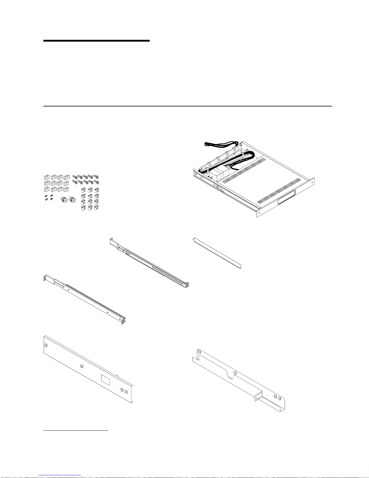
Check Your Inventory
you unpack the kit, ensure that you have the following items:
Miscellaneous Hardware Kit contains:
cage nuts
clip nuts
12
Phillips screws
10
8-32 screws
4
thumbscrews
2
Two outer rails
One keyboard tray with built-in flat-panel monitor
One rail alignment spacer
One right-side console-switch mounting bracket
1. Racks are measured in vertical increments of 1.75 inches each. Each 1.75-inch increment is called an “EIA.” In some countries,
the same increment may be referred to as a “U.”
One left-side console-switch mounting bracket (for
routing video, keyboard, and mouse cables when a
console switch is installed)
1
Page 16
h
h
h
h
h
h
v
v
v
2
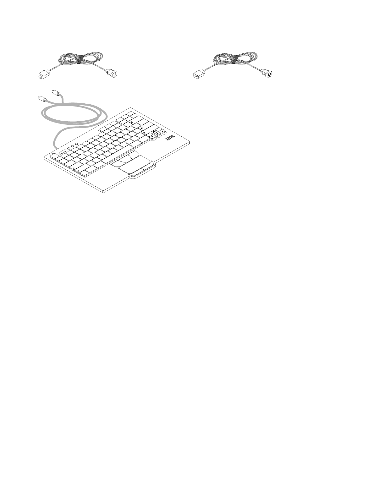
h
One 1.8 m (6 ft) power cord
One 2.4-m (8-ft) IEC connector power cable
One thin keyboard with built-in pointing device
Keyboard extension cable
Mouse extension cable
One CD containing Windows keyboard and mouse
drivers (not for use with
Eserver
pSeries systems or
any AIX, Linux, or OS/400-based system)
Monitor and keyboard documentation (including this
document)
Pause
ScrLk
PrtSc
9
I
8
U
7
Y
6
H
T
5
G
4
R
3
Esc
F1 F2 F3 F4 F5 F6 F7 F8 F9 F10 F11 F12 Delete
~
`
E
2
W
S
1
Q
A
Caps Lock
Shift
Z
Fn Ctrl
Tab
B
F
V
D
C
X
Alt
PgUp
PgDn
Home
End
Insert
Backspace
|
\
+
=
}
]
_
-
P
0
O
L
K
J
M
N
Enter
{
[
“
Shift
‘
:
;
?
/
>
.
Ctrl
<
,
Alt
You might need the following tools to install the 7316-TF3 17-Inch Flat Panel Rack-Mounted Monitor and
Keyboard:
Scissors
Phillips screwdriver
Flat-blade screwdriver
further information, refer to the documentation provided with your rack cabinet or console switch.
For
7316-TF3 17-Inch Flat Panel Rack-Mounted Monitor and Keyboard: Installation and Maintenance Guide
Page 17

of
an
To
v Do
To
1.
2.
3.
4.
To
1.
2.
3.
4.
5.
Chapter 2. Installing the 7316-TF3 17-Inch Flat Panel
Rack-Mounted Monitor and Keyboard
The IBM 7316-TF3 17-Inch Flat Panel Rack-Mounted Monitor and Keyboard occupies 1.75 inches (1 EIA)
rack-mounting space in a rack cabinet. You can use the brackets that are provided with this kit to install
optional console switch in the same rack-mounting space as the monitor console kit.
Safety Considerations
Observe the following safety precautions when installing this monitor and keyboard.
DANGER
Electrical
avoid a shock hazard:
reconfiguration of this product during an electrical storm.
Connect all power cords to a properly wired and grounded electrical outlet. Ensure outlet
v
supplies proper voltage and phase rotation according to the system rating plate.
v
Connect any equipment that will be attached to this product to properly wired outlets. v When
possible, use one hand only to connect or disconnect signal cables.
v
Never turn on any equipment when there is evidence of fire, water, or structural damage.
Disconnect the attached power cords, telecommunications systems, networks, and modems
v
before you open the device covers, unless instructed otherwise in the installation and
configuration procedures.
Connect and disconnect cables as described below when installing, moving, or opening
v
covers on this product or attached devices.
voltage and current from power, telephone, and communication cables are hazardous.
not connect or disconnect any cables or perform installation, maintenance, or
Disconnect:
Turn everything OFF (unless instructed otherwise).
Remove power cords from the outlet.
Remove signal cables from connectors.
Remove all cables from devices.
Connect:
Turn everything OFF (unless instructed otherwise).
Attach all cables to devices.
Attach signal cables to connectors.
Attach power cords to outlet.
Turn device ON.
D005
CAUTION:
This product is equipped with a 3-wire (two conductors and ground) power cable and plug. Use
this power cable with a properly grounded electrical outlet to avoid electrical shock.
C018
Note:
The ac power-interface connector is considered the main power disconnect device.
3
Page 18

To
1.
2.
4
Installing the Monitor and Keyboard Tray into a Rack
Removing rack doors and side panels might make installation easier. For additional information about
removing the doors, refer to the documentation that was provided with your rack cabinet.
install the tray into the rack:
Select a location in the rack for the monitor and keyboard tray.
Using the following illustration as a guide, install 4 cage nuts (on square-holed rack flanges) or 4 clip
nuts (round-holed rack flanges) in the same EIA positions on the front and rear of the rack.
Note: If you are planning to install the optional console switch, also install a cage nut or clip nut in
the center-rear position as shown in the following illustration.
7316-TF3 17-Inch Flat Panel Rack-Mounted Monitor and Keyboard: Installation and Maintenance Guide
Page 19

4.
5.
3.
Loosen the two rail-adjustment screws on each of the outer slide rails. Then, extend the rails to their
maximum outward adjustment.
Rail-adjustment
screws
Adjust the outer slide-rail brackets to fit the depth of the rack cabinet. Then, loosely attach the front of
the slide-rail brackets to fit the depth of the rack cabinet using four screws from the miscellaneous
hardware kit. The screws should be finger-tight to allow adjustment of the rails.
Note: Make sure that the slide-rail brackets extend outside of the rack-cabinet mounting flanges. Do
not install screws in the middle holes on the front or rear of the slide-rail brackets. These holes
will be used to attach thumbscrews or optional console-switch mounting brackets, respectively,
later in this procedure.
Loosely attach (finger-tight) the back of the slide-rail brackets to the rack cabinet using four screws
from the miscellaneous hardware kit. Make sure that the slide-rail brackets extend outside of the
Chapter 2. Installing the 7316-TF3 17-Inch Flat Panel Rack-Mounted Monitor and Keyboard
5
Page 20

6.
5. 7.
8.
to
6
rack-cabinet mounting flanges.
Tighten the two rail-adjustment screws on each of the outer rails that you loosened in step 3 on page
Insert the rail-alignment spacer into the slide-rail middle holes. The rail-alignment spacer must wrap
around the rails (top and bottom of the front of the rail) to align them correctly. Tighten the front four
screws; then, remove the spacer.
Note: Do not tighten the four rear slide-rail bracket screws yet.
Rail-alignment spacer
Extend the inner part of the rails mounted in the rack, then slide the ball-bearing assemblies forward
the front of the rails.
7316-TF3 17-Inch Flat Panel Rack-Mounted Monitor and Keyboard: Installation and Maintenance Guide
Page 21

9.
Carefully slide the flat-panel monitor and keyboard tray into the ball-bearing assemblies in the rails.
10.
Press the release latches and push the flat-panel monitor and keyboard tray completely into the rack.
There will be resistance initially as the ball-bearing assemblies align between the inner and outer
rails. Pull the tray out halfway, then push it back in to seat the tray in the rails. Do this a few times
until the tray moves smoothly in the rails.
Attention: The video cable is connected to the flat-panel monitor. When you install the tray in the
rack cabinet, make sure you do not pinch or cut the video cable.
11.
Push the tray into the rack and tighten the four rear slide-rail bracket screws.
12.
Place the keyboard on a stable flat surface and remove the two adhesive rubber pads at each end of
the bottom of the new keyboard. (If you leave the rubber pads on the keyboard, they will extend into
the space below the tray.)
Attention: Do not extend the keyboard feet. The flat-panel monitor screen might be damaged if the
feet are extended when the monitor is closed.
Chapter 2. Installing the 7316-TF3 17-Inch Flat Panel Rack-Mounted Monitor and Keyboard
7
Page 22

F
n
C
tr
l
C
tr
l
A
lt
A
lt
A
Z
S
X
D
C
F
V
G
B
H
N
J
M
K
<
,
L
>
.
:
;
?
/
“
‘
E
n
te
r
S
h
ift
S
h
ift
C
a
p
s
L
o
c
k
E
s
c
F
1
F
2
F
3
F
4
F
5
F
6
F
7
F
8
F
9
F
1
0
F
1
1
F
1
2
D
e
le
te
In
s
e
r
t
P
r
tS
c
E
n
d
S
c
rL
k
Pa
u
s
e
1
Q
2
W
3
E
4
R
5
T
6
Y
7
U
8
I
9
O
0
P
{
[
}
]
|
\
B
a
c
k
s
p
a
Ta
b
~
`
_
-
+
=
8
13.
Pull the tray out of the rack until it is extended fully on the rails.
14.
Carefully lift the front of the flat-panel monitor, then raise the monitor to the full upright position.
15.
Carefully insert the keyboard into the tray. Then, route the keyboard-and-mouse cable through the
cord clip on the bottom of the tray, up through the opening on the right side of the tray, and toward
the cable-management arm. Pull the full length of the cable through the opening.
Keyboard-and-mouse
cable routing
16.
Lay the keyboard-and-mouse cable on the tray just behind the monitor. Make sure that the cable will
not catch on other devices in the rack when the tray is pushed into the rack. The cables will be
routed through the cable-management arm in the next steps.
17.
Carefully lower the monitor to the down position and then push the tray all the way into the rack and
secure the front of the tray to the rack using the thumbscrews.
18.
From the rear of the rack, remove the shipping straps that are holding the cable-management arm to
the tray.
19.
Route the keyboard-and-mouse cable through the cable-management arm and secure the cables
using the existing cable straps.
7316-TF3 17-Inch Flat Panel Rack-Mounted Monitor and Keyboard: Installation and Maintenance Guide
Page 23

20.
Still from the rear of the rack, remove the rail-adjustment screw closest to the back of the rack from
the left-slide rail. Attach the cable-management arm to the rail using this screw.
21.
Connect the video, keyboard, and mouse connectors to either a server or optional console switch in
the rack cabinet. If you are installing the optional console switch, go to “Installing the Optional
Console Switch” on page 10 now and complete the steps described. Otherwise, go to the next step to
complete the installation of your monitor and keyboard tray.
22.
Connect the power cord to the short jumper cord on the cable-management arm.
23.
Connect all cables and signal connectors to their correct device or connector.
24.
Make sure that all power switches are turned off, then connect the power cord to a properly grounded
electrical outlet or power distribution unit (PDU).
Attention: Before connecting the ac power cord to the dc adapter outlet, make sure the voltage of
the local electrical supply is within the range of 100 - 240 volt ac and that you connect the unit to a
properly rated circuit.
25.
Fully extend the tray from the front of the rack cabinet and neatly route cables within the rack cabinet,
securing them with cable straps along the way.
26.
For information about operating the monitor, see the flat-panel monitor documentation that was
provided with this kit. For information about operating the keyboard, see the keyboard documentation.
Chapter 2. Installing the 7316-TF3 17-Inch Flat Panel Rack-Mounted Monitor and Keyboard
9
Page 24

By
To
1.
10
Note: When the monitor and keyboard are not in use, if the rack cabinet is in a vibration-prone area, or
during cabinet relocation, tighten the two thumbscrews on the front of the tray to secure the tray
inside the rack cabinet.
Thumbscrew
Installing the Optional Console Switch
Attention: Before beginning, read “Safety Considerations” on page 3.
You can use the console switch (Feature Code 4200 or 4202) to attach more than one server to a single
monitor and keyboard. The console-switch option is available separately, but custom mounting brackets for
the switch come with this kit.
installing the console switch behind the monitor and keyboard tray, both can occupy the same space in
the rack. To install the console switch behind the tray, use the brackets provided with this kit.
Attention: The console switch will extend beyond the rear rack-mounting flanges when you install the
switch behind the tray.
install a console switch behind the tray, complete the following steps:
Attach the left-side bracket to the left side of the console switch using two 8-32 screws. Then, attach
the right-side bracket to the right side of the console switch.
Note: The left-side bracket has a channel for you to route the power, video, and keyboard-and-mouse
cables. Make sure that you attach the brackets to the console switch so that the channel on the
left-side bracket faces upward.
Console switch
Left-side bracket
7316-TF3 17-Inch Flat Panel Rack-Mounted Monitor and Keyboard: Installation and Maintenance Guide
8
7
6
5
4
3
2
1
A
Right-side bracket
Page 25

1
A
2
of
3.
on
4.
5. To
2.
Install the console switch behind the flat-panel monitor and keyboard tray using four (two on each side)
the Phillips screws supplied in your miscellaneous hardware kit.
Route the power, video, and keyboard-and-mouse cables through the channel in the left-side bracket
the console switch. Then, connect the video, keyboard, and mouse connectors to the console
switch.
Console
switch screw
8
7
6
5
4
3
2
1
A
Console
switch
screw
For information about connecting the flat-panel monitor, thin keyboard, and servers to the console
switch, see the documentation provided with the console switch.
finish connecting the power cords, routing cables, and cable straps, go back to step 22 on page 9.
Chapter 2. Installing the 7316-TF3 17-Inch Flat Panel Rack-Mounted Monitor and Keyboard
11
Page 26

12
7316-TF3 17-Inch Flat Panel Rack-Mounted Monitor and Keyboard: Installation and Maintenance Guide
Page 27

v
v To
v
v Be
v
v
v If
v
v
v If
v
v
v
v
v
Chapter 3. Using the Monitor
Note: The complete monitor manual is available at http://www.osdmanual.com. Match the OSD displayed
when the Menu button is pushed with one of the OSD choices on the website.
When using the monitor, observe the following basic guidelines:
Never insert anything metallic into the openings in the cabinet of the LCD monitor; doing so can create
the danger of electric shock.
avoid electric shock, never open the LCD monitor case. The case should only be opened by trained
service personnel.
Never use your LCD monitor if the power cord has been damaged. Do not allow anything to rest on the
power cord or pinch the power cord.
sure to hold the plug, not the cord, when disconnecting the LCD monitor from an electric socket.
Openings in the LCD monitor case are provided for ventilation. To prevent overheating, these openings
should not be blocked or covered. Install the unit in a well-ventilated area.
Place your LCD monitor in a location with low humidity and a minimum amount of dust.
the LCD monitor accidentally gets wet, unplug it and contact your IBM representative or reseller
immediately. You can clean the LCD monitor with a damp cloth when necessary, but be sure to unplug
the LCD monitor first.
Place the LCD monitor on a solid surface and treat it carefully. The screen is made of thin glass with a
plastic front surface and can be damaged if dropped, hit, or scratched. Do not clean the front panel with
ketone-type materials (for example, acetone), ethyl alcohol, toluene, ethyl acid, methyl, or chloride.
These materials might damage the monitor.
Locate your LCD monitor near an easily accessible ac outlet.
there are any unusual sounds or smells coming from your LCD monitor, unplug it immediately and
contact your IBM representative or reseller.
High temperature can cause problems. Keep your LCD monitor away from direct sunlight, heaters, and
other sources of heat.
Unplug your LCD monitor when it is going to be left unused for an extended period of time.
Unplug your LCD monitor from the ac outlet before any service.
The maximum operating ambient temperature is 40°C.
Connect the mouse (touchpad, pointer) and keyboard only to listed Information Technology Equipment
(ITE) with Limited Power Source (LPS) keyboard and mouse (touchpad, pointer) outputs.
User Controls
These controls available on the front of the monitor:
Auto Activates the auto adjustment function. The
displayed.
Exit Exits the OSD (On-screen display) function or returns to the previous menu.
Power Indicator
Indicates the status of monitor operation.
Green Normal
Black Power OFF
Amber
Power saving mode or disconnection of signal cable
Power
Button
Turns on and off the monitor power.
Auto adjustment is being processed
message is
13
Page 28

v
v
v
v
v
v
20
5% to
14
t/u
Moves the selector left and right on the OSD menu
Increases or deceases the value of the selected adjustment or selects the proper setting
Adjusts the brightness of the back light lamp by pressing the t or u buttons without the OSD
menu (Hot key)
Menu
Opens the OSD menu
Selects the function to be adjusted
Moves the selector down on the OSD menu
Technical Specifications
LCD Panel
Size
Display area
Type
Pixel pitch
17.0″ Diagonal
337.92 (H) x 270.336 (V) mm
a-Si TFT active matrix
0.264 (H) x 0.264 (W) mm
Frequency
Horizontal 30 – 61 kHz
Vertical 50 – 75 Hz
Display Color
16.7M Colors
Display Resolution
Optimum Mode 1280 x 1024 @ 60 Hz
Maximum Mode 1280 x 1024 @ 75 Hz
Input Signal
Sync HN Separate, TTL, Positive or Negative
Sync HN Composite, TTL, Positive or Negative
Sync-on-green 0.3 Vp-p, Negative
Video Signal 0.700 Vp-p @ 75 ohm, Positive
Power Supply
100-240 volt ac, 60 Hz – 50 Hz to 12V/ 3.75A
Power Consumption
Normal
Power Saving
Less than 3 Watts
Watts
Environmental Considerations
Operating Temperature
Operating Humidity
Storage Temperature
(0°C to 40°C)
10% to 80%
(-25°C to 60°C)
Storage Humidity
7316-TF3 17-Inch Flat Panel Rack-Mounted Monitor and Keyboard: Installation and Maintenance Guide
95%
Page 29

1.
a.
b.
c.
d.
Chapter 4. Hardware Maintenance Information
This chapter contains information about IBM customer-replaceable units (CRUs) for the 7316-TF3 17-Inch
Flat Panel Rack-Mounted Monitor and Keyboard.
Customer-Replaceable Unit Part Numbers
Only two components of the 7316-TF3 17-Inch Flat Panel Rack-Mounted Monitor and Keyboard are
customer replaceable: the entire kit itself (CRU part number 80P3750) and the thin keyboard with built-in
pointing device. If any component other than the keyboard fails, you must order the CRU part number for
the complete 7316-TF3 17-Inch Flat Panel Rack-Mounted Monitor and Keyboard unit.
Note: A Repair Identification (RID) tag is included with all replacement systems. Record the beginning
date of the original warranty period on the RID tag and attach it to the replacement monitor.
This following table contains a listing of the CRU part numbers available at the time this document was
published. When ordering a replacement keyboard, ensure that the part number printed on the bottom of
keyboard matches the CRU part number you are ordering.
CRU part number
80P3750
89P8500
89P8508
89P8505
89P8507
89P8509
89P8513
89P8522
89P8527
89P8514
89P8524
89P8523
89P8519
89P8502
89P8516
89P8520
89P8518
Description
Display assembly
Keyboard, US English
Keyboard, French Canadian
Keyboard, Danish
Keyboard, French
Keyboard, German
Keyboard, Italian
Keyboard, Spanish
Keyboard, UK English
Keyboard, Japanese
Keyboard, Swiss
Keyboard, Swedish/Finnish
Keyboard, Portuguese
Keyboard, Belgian-UK
Keyboard, LA Spanish
Keyboard, Russian
Keyboard, Polish
Replacing the Display and Keyboard
Replacing the flat-panel monitor and keyboard involves reversing the installation steps described earlier in
this document. To remove and replace the console kit, complete the following steps.
Turn off and disconnect power and cables in the following order:
Turn off all power switches on the monitor, devices, and optional switches.
Remove all power cords from power outlets.
Remove signal cables from connectors.
Remove cables from devices.
15
Page 30

If
3.
4.
5.
16
2.
you installed a console switch in the rear of the rack cabinet, remove the console switch from the
rack.
Remove the screw that attaches the cable-management arm to the outer slide-rail bracket.
Fully extend the monitor and keyboard tray from the front of the rack cabinet. Push in the release
latch on each side of the tray and slide the monitor and keyboard tray assembly out of the rack.
Remove the eight screws that attach the outer slide rails to the rack cabinet and remove the rails
from the cabinet.
7316-TF3 17-Inch Flat Panel Rack-Mounted Monitor and Keyboard: Installation and Maintenance Guide
Page 31

to
7.
6.
Loosen the four rail-adjustment screws on both new outer slide-rail brackets and extend the brackets
their maximum outward adjustment.
Rail-adjustment
screws
Adjust the new outer slide-rail brackets to fit the depth of the rack cabinet. Attach the front of the new
slide-rail brackets to the rack cabinet using four screws. Make sure that the slide-rail brackets extend
outside of the rack-cabinet mounting flanges.
Note: Do not install screws in the slide-rail bracket middle holes. These holes are for the
thumbscrews on the front of the tray.
Chapter 4. Hardware Maintenance Information
17
Page 32

18
8.
Repeat the previous step for the rear of the slide-rail brackets. Again, make sure that the slide-rail
brackets extend outside of the rack-cabinet mounting flanges.
7316-TF3 17-Inch Flat Panel Rack-Mounted Monitor and Keyboard: Installation and Maintenance Guide
Page 33

9.
Tighten the two rail-adjustment screws on each of the outer rails that you loosened in step 6 on page
17.
10.
Loosen the front four slide-rail bracket screws; then, insert the rail-alignment spacer into the slide-rail
middle holes. The rail-alignment spacer must wrap around the rails to align them correctly. Tighten
the front four screws and remove the spacer.
Note: Do not tighten the four rear slide-rail bracket screws at this time.
Rail-alignment spacer
11.
Remove the screw and the nut that attach the inner slide rails to the monitor and keyboard assembly.
Attach the new inner slide rails to the tray.
12.
For instructions on reinstalling the monitor and keyboard tray in the rack cabinet, go to “Installing the
Monitor and Keyboard Tray into a Rack” on page 4.
13.
Install any other devices that you removed from the rack cabinet.
Chapter 4. Hardware Maintenance Information
19
Page 34

To
1.
of
2.
3.
4.
5.
6.
7.
20
Replacing the Keyboard
replace the keyboard, complete the following steps:
Place the keyboard on a stable flat surface and remove the two adhesive rubber pads from the bottom
the new keyboard. (If you leave the rubber pads on the keyboard, they will extend into the space
below the tray.)
Attention: Do not extend the keyboard feet. The flat-panel monitor screen might be damaged if the
feet are extended when the monitor is closed.
Turn off the monitor and disconnect the monitor cord.
Disconnect the keyboard and mouse connectors from the server or console switch.
Unscrew the thumbscrews (if installed), then fully extend the monitor and keyboard tray. Remove the
keyboard-and-mouse cable from the cable-management arm.
Carefully lift the front of the flat-panel monitor and raise the monitor to the full upright position.
Remove the old keyboard from the keyboard tray.
Carefully insert the new keyboard into the tray and route the keyboard-and-mouse cable through the
cord clip on the bottom, through the opening on the right side of the tray, and toward the
7316-TF3 17-Inch Flat Panel Rack-Mounted Monitor and Keyboard: Installation and Maintenance Guide
Page 35

F
n
C
tr
l
C
tr
l
A
lt
A
lt
A
Z
S
X
D
C
F
V
G
B
H
N
J
M
K
<
,
L
>
.
:
;
?
/
“
‘
E
n
te
r
S
h
ift
S
h
ift
C
a
p
s
Lo
c
k
E
s
c
F
1
F
2
F
3
F
4
F
5
F
6
F
7
F
8
F
9
F
10
F
1
1
F
1
2
D
ele
te
In
s
er
t
P
r
tS
c
E
n
d
S
c
rL
k
Pa
u
s
e
1
Q
2
W
3
E
4
R
5
T
6
Y
7
U
8
I
9
O
0
P
{
[
}
]
|
\
B
a
c
k
s
p
a
Ta
b
~
`
_
-
+
=
8.
9.
cable-management arm. Pull the full length of the cable through the opening.
Keyboard-and-mouse
cable routing
Secure the keyboard-and-mouse cable to the cable-management arm using the existing cable straps.
Reconnect the keyboard-and-mouse cable to the server or console switch.
Chapter 4. Hardware Maintenance Information
21
Page 36

22
7316-TF3 17-Inch Flat Panel Rack-Mounted Monitor and Keyboard: Installation and Maintenance Guide
Page 37

a
Appendix A. Communications Statements
The following statement applies to this product. The statement for other products intended for use with this
product appears in their accompanying documentation.
Federal Communications Commission (FCC) Statement
Note: This equipment has been tested and found to comply with the limits for a Class A digital device,
pursuant to Part 15 of the FCC Rules. These limits are designed to provide reasonable protection
against harmful interference when the equipment is operated in a commercial environment. This
equipment generates, uses, and can radiate radio frequency energy and, if not installed and used in
accordance with the instruction manual, may cause harmful interference to radio communications.
Operation of this equipment in a residential area is likely to cause harmful interference in which
case the user will be required to correct the interference at his own expense.
Properly shielded and grounded cables and connectors must be used in order to meet FCC emission
limits. Neither the provider nor the manufacturer is responsible for any radio or television interference
caused by using other than recommended cables and connectors or by unauthorized changes or
modifications to this equipment. Unauthorized changes or modifications could void the user’s authority to
operate the equipment.
This device complies with Part 15 of the FCC Rules. Operation is subject to the following two conditions:
(1) this device may not cause harmful interference, and (2) this device must accept any interference
received, including interference that may cause undesired operation.
Avis de conformité aux normes du ministère des Communications du
Canada
Cet appareil numérique de la classe A est conforme à la norme NMB-003 du Canada.
Canadian Department of Communications Compliance Statement
This Class A digital apparatus complies with Canadian ICES-003..
Australia and New Zealand Class A statement
Attention: This is a Class A product. In a domestic environment this product may cause radio
interference in which case the user may be required to take adequate measures.
United Kingdom Telecommunications Safety Requirements
This equipment is manufactured to the International Safety Standard EN60950 and as such is approved in
the UK under the General Approval Number NS/G/1234/J/100003 for indirect connection to the public
telecommunication network.
The network adapter interfaces housed within this equipment are approved separately, each one having its
own independent approval number. These interface adapters, supplied by the manufacturer, do not use or
contain excessive voltages. An excessive voltage is one which exceeds 70.7 V peak ac or 120 V dc. They
interface with this equipment using Safe Extra Low Voltages only. In order to maintain the separate
(independent) approval of the manufacturer’s adapters, it is essential that other optional cards, not
supplied by the manufacturer, do not use main voltages or any other excessive voltages. Seek advice from
competent engineer before installing other adapters not supplied by the manufacturer.
23
Page 38

in
24
European Union EMC Directive Conformance Statement
This product is in conformity with the protection requirements of EU Council Directive 89/336/EEC on the
approximation of the laws of the Member States relating to electromagnetic compatibility. The
manufacturer cannot accept responsibility for any failure to satisfy the protection requirements resulting
from a non-recommended modification of the product, including the fitting of option cards supplied by third
parties. Consult with your dealer or sales representative for details on your specific hardware.
This product has been tested and found to comply with the limits for Class A Information Technology
Equipment according to CISPR 22 / European Standard EN 55022. The limits for Class A equipment were
derived for commercial and industrial environments to provide reasonable protection against interference
with licensed communication equipment.
Attention: This is a Class A product. In a domestic environment this product may cause radio
interference in which case the user may be required to take adequate measures.
Electromagnetic Interference (EMI) Statement - Taiwan
The following is a summary of the EMI Taiwan statement above.
Warning: This is a Class A product. In a domestic environment this product may cause radio interference
which case the user will be required to take adequate measures.
Chinese Class A warning statement
VCCI Statement
The following is a summary of the VCCI Japanese statement in the box above.
7316-TF3 17-Inch Flat Panel Rack-Mounted Monitor and Keyboard: Installation and Maintenance Guide
Page 39

This is a Class A product based on the standard of the Voluntary Control Council for Interference by
Information Technology Equipment (VCCI). If this equipment is used in a domestic environment, radio
disturbance may arise. When such trouble occurs, the user may be required to take corrective actions.
Radio Protection for Germany
Dieses Gerät ist berechtigt in Übereinstimmung mit Dem deutschen EMVG vom 9.Nov.92 das
EG–Konformitätszeichen zu führen.
Der Aussteller der Konformitätserklärung ist die IBM Germany.
Dieses Gerät erfüllt die Bedingungen der EN 55022 Klasse A. Für diese von Geräten gilt folgende
Bestimmung nach dem EMVG:
Geräte dürfen an Orten, für die sie nicht ausreichend entstört sind, nur mit besonderer Genehmigung des
Bundesministers für Post und Telekommunikation oder des Bundesamtes für Post und Telekommunikation
betrieben werden. Die Genehmigung wird erteilt, wenn keine elektromagnetischen Störungen zu erwarten
sind.
(Auszug aus dem EMVG vom 9.Nov.92, Para.3, Abs.4)
Hinweis
Dieses Genehmigungsverfahren ist von der Deutschen Bundespost noch nicht veröffentlicht worden.
International Electrotechnical Commission (IEC) Statement
This product has been designed and built to comply with IEC 60950.
Appendix A. Communications Statements
25
Page 40

26
7316-TF3 17-Inch Flat Panel Rack-Mounted Monitor and Keyboard: Installation and Maintenance Guide
Page 41

at
Appendix B. Environmental Notices
Product Recycling and Disposal
This unit contains materials such as circuit boards, cables, electromagnetic compatibility gaskets and
connectors which may contain lead and copper/beryllium alloys that require special handling and disposal
end of life. Before this unit is disposed of, these materials must be removed and recycled or discarded
according to applicable regulations. IBM offers product-return programs in several countries. For country
specific instructions refer to the following web site: http://www.ibm.com/ibm/environment/products/prp.phtml
This product may contain a sealed lead acid, nickel cadmium, nickel metal hydride, lithium, or
lithium ion battery. Consult your user manual or service manual for specific battery information.
The battery must be recycled or disposed of properly. Recycling facilities may not be available in
your area. For information on disposal of batteries, contact your local waste disposal facility.
27
Page 42

Dette produkt kan indeholde et forseglet batteri, der indeholder bly,
nikkel-kadmium, nikkel-metal-hydrid, litium eller litium-ion.
Der er flere oplysninger om batteriet i bruger- eller servicevejledningen.
Batteriet må ikke kasseres sammen med det almindelige affald.
Batteriet skal kasseres i henhold til de lokale bestemmelser.
Spørg eventuelt kommunens tekniske forvaltning (Miljøafdelingen).
Dit product bevat mogelijk een afgesloten batterij van het type lood/zuur ,
nikkel/cadmium, nikkel/metaalhydride, lithium, of lithiumionen. Raadpleeg
het handboek voor de gebruiker of het servicehandboek voor informatie over
de batterij. De batterij moet correct worden gerecycled of weggegooid.
Mogelijk zijn er in uw regio geen K CA-inzamelingspunten. Meer
informatie over het verwerken van gebruikte batterijen kunt u verkrijgen bij
uw afvalverwerkingsbedrijf .
Dieses Produkt enthält eine auslaufsichere Blei-, Nickel-Cadmium-, Nickelmetallhydrid-, Lithium- oder Lithiumionenbatterie. Spezifische Informationen
zur Batterie entnehmen Sie bitte dem Benutzer- oder Servicehandbuch. Die
Batterie muss wieder verwertet oder als Sondermüll entsorgt werden. Es ist
möglich, dass es in Ihrer Nähe keine Wiederverwertungsanlage gibt. Weitere
Informationen zur Entsorgung von Batterien erhalten Sie von Ihrem örtlichen
Müllentsorgungsunternehmen.
28
7316-TF3 17-Inch Flat Panel Rack-Mounted Monitor and Keyboard: Installation and Maintenance Guide
Page 43

Questo prodotto potrebbe contenere una batteria al piombo, al
nichel-cadmio, all ’idruro di nichel, al litio o agli ioni di litio. Consultare il
manuale utente o il manuale di assistenza per informazioni specifiche sulla
batteria. La batteria deve essere appropriatamente riciclata o smaltita.
Il servizio per il riciclaggio potrebbero non essere disponibile nella vostra
zona. Per informazioni sullo smaltimento delle batterie, contattare l ’azienda
preposta per lo smaltimento dei rifiuti.
Appendix B. Environmental Notices
29
Page 44

Produkten kan innehålla ett förseglat batteri av någon av typerna
blyackumulator , nickel-kadmium, nickel-metallhydrid, litium eller litiumjon.
Detaljerad batteriinformation finns I användar - eller servicehandboken.
Batteriet måste lämnas till återvinning eller kastas på ett miljösäkert sätt.
Det kanske inte finns några återvinningsmöjligheter därdubor .När det
gäller omhändertagande av batterier ber vi att få hänvisa till myndigheternas
anvisningar i respektive land.
30
7316-TF3 17-Inch Flat Panel Rack-Mounted Monitor and Keyboard: Installation and Maintenance Guide
Page 45

of
In the United States, IBM has established a collection process for reuse, recycling, or proper disposal of
used IBM sealed lead acid, nickel cadmium, nickel metal hydride, and other battery packs from IBM
Equipment. For information on proper disposal of these batteries, please contact IBM at 1-800-426-4333.
Have the IBM part number listed on the battery available prior to your call.
Environmental Design
The environmental efforts that have gone into the design of this system signify IBM’s commitment to
improve the quality of its products and processes. Some of these accomplishments include the elimination
the use of Class 1 ozone-depleting chemicals in the manufacturing process and reductions in
manufacturing wastes. For more information, contact an IBM account representative.
Appendix B. Environmental Notices
31
Page 46

32
Ergonomic Information
After you have set up your system, we encourage you to visit the Healthy Computing Web site. Good
ergonomic practice is important to get the most from your workstation and to avoid discomfort. This means
that the equipment and the workplace should be arranged to suit your individual needs and the kind of
work you do.
The Healthy Computing Web site gives ergonomic guidelines to help you understand the ergonomic
considerations that you should know when working at a computer workstation. The address is:
http://www.us.pc.ibm.com/healthycomputing
7316-TF3 17-Inch Flat Panel Rack-Mounted Monitor and Keyboard: Installation and Maintenance Guide
Page 47

in
Appendix C. Notices
This information was developed for products and services offered in the U.S.A.
The manufacturer may not offer the products, services, or features discussed in this document in other
countries. Consult the manufacturer’s representative for information on the products and services currently
available in your area. Any reference to the manufacturer’s product, program, or service is not intended to
state or imply that only that product, program, or service may be used. Any functionally equivalent product,
program, or service that does not infringe any intellectual property right of the manufacturer may be used
instead. However, it is the user’s responsibility to evaluate and verify the operation of any product,
program, or service.
The manufacturer may have patents or pending patent applications covering subject matter described in
this document. The furnishing of this document does not give you any license to these patents. You can
send license inquiries, in writing, to the manufacturer.
The following paragraph does not apply to the United Kingdom or any country where such
provisions are inconsistent with local law: THIS MANUAL IS PROVIDED ″AS IS″ WITHOUT
WARRANTY OF ANY KIND, EITHER EXPRESSED OR IMPLIED, INCLUDING, BUT NOT LIMITED TO,
THE IMPLIED WARRANTIES OF NON-INFRINGEMENT, MERCHANTABILITY OR FITNESS FOR A
PARTICULAR PURPOSE. Some states do not allow disclaimer of express or implied warranties in certain
transactions; therefore, this statement may not apply to you.
This information could include technical inaccuracies or typographical errors. Changes are periodically
made to the information herein; these changes will be incorporated in new editions of the publication. The
manufacturer may make improvements and/or changes in the product(s) and/or the program(s) described
this publication at any time without notice.
Information concerning products made by other than the manufacturer was obtained from the suppliers of
those products, their published announcements, or other publicly available sources. The manufacturer has
not tested those products and cannot confirm the accuracy of performance, compatibility or any other
claims related to products made by other than the manufacturer. Questions on the capabilities of products
made by other than the manufacturer should be addressed to the suppliers of those products.
33
Page 48

34
7316-TF3 17-Inch Flat Panel Rack-Mounted Monitor and Keyboard: Installation and Maintenance Guide
Page 49

10
4
4
14
Index
B
battery
disposal,
recycling 27
C
console switch
installing
rack preparation 4
customer-replaceable parts 15
E
ergonomic information 32
F
flat-panel monitor and keyboard tray, installing 3
H
highlighting xi
I
inner slide rails, replacing 15
installing
console
flat-panel monitor and keyboard tray 3
switch 10
recycling 27
replacing
customer-replaceable
inner slide rails 15
keyboard 20
outer slide rails 15
slide rails 15
S
safety v
slide rails, replacing 15
specifications
technical
W
Web sites
ergonomic
information 32
unit (CRU) part numbers 15
K
keyboard, replacing 20
M
monitor
installing
user controls 13
using 13
O
outer slide rails, replacing 15
P
parts
customer-replaceable
unit (CRU) part numbers 15
product disposal 27
R
rails
installing
35
Page 50

36
7316-TF3 17-Inch Flat Panel Rack-Mounted Monitor and Keyboard: Installation and Maintenance Guide
Page 51

h
h No
Readers’ Comments — We’d Like to Hear from You
7316-TF3 17-Inch Flat Panel Rack-Mounted Monitor and Keyboard
Installation and Maintenance Guide
Publication No. SA38-0643-00
Overall, how satisfied are you with the information in this book?
Very Satisfied Satisfied Neutral Dissatisfied Very Dissatisfied
Overall satisfaction hhhhh
How satisfied are you that the information in this book is:
Very Satisfied Satisfied Neutral Dissatisfied Very Dissatisfied
Accurate hhhhh
Complete hhhhh
Easy to find hhhhh
Easy to understand hhhhh
Well organized hhhhh
Applicable to your tasks hhhhh
Please tell us how we can improve this book:
Thank you for your responses. May we contact you?
When you send comments to IBM, you grant IBM a nonexclusive right to use or distribute your comments in any
way it believes appropriate without incurring any obligation to you.
Name
Company or Organization
Phone No.
Yes
Address
Page 52

or
___________________________________________________________________________________________________
Readers’ Comments — We’d Like to Hear from You
SA38-0643-00
Fold
_________________________________________________________________________________________
and Tape
Please do not staple
Fold and Tape
NO
POSTAGE
NECESSARY
MAILED IN THE
IF
UNITED
STATES
Cut or Fold
Line
Along
BUSINESS REPLY MAIL
FIRST-CLASS MAIL PERMIT NO. 40 ARMONK, NEW YORK
POSTAGE WILL BE PAID BY ADDRESSEE
Information Development
Department H6DS-905-6C006
11501 Burnet Road
Austin, TX 78758-3493
_________________________________________________________________________________________
Fold
and Tape
Please do not staple
Fold and Tape
SA38-0643-00
Fold
Cut
Along Line
Page 53

Page 54

Part Number: 80P3752
Printed in USA
May 2004
SA38-0643-00
80P3752
P/N:
(1P)
 Loading...