

Page 1

ERserver
xSeries 445 Type 8870
Hardware Maintenance Manual and Troubleshooting
Guide
Page 2

Page 3

ER s e r v e r
xSeries 445 Type 8870
Hardware Maintenance Manual and Troubleshooting
Guide
Page 4

Note: Before using this information and the product it supports, read Appendix B, “Notices,” on page
301.
The most recent version of this document is available at http://www.ibm.com/pc/support.
23rd Edition (April 2005)
© Copyright International Business Machines Corporation 2003. All rights reserved.
US Government Users Restricted Rights – Use, duplication or disclosure restricted by GSA ADP Schedule Contract
with IBM Corp.
Page 5

About this manual
This manual contains diagnostic information, a Symptom-to-FRU index, service
information, error codes, error messages, and configuration information for the IBM
Eserver
™
xSeries
Important: This manual is intended for trained servicers who are familiar with IBM
xSeries products. Before servicing an IBM product, be sure to review
“Safety information” on page 257.
Important safety information
Be sure to read all caution and danger statements in this book before performing
any of the instructions.
Leia todas as instruções de cuidado e perigo antes de executar qualquer operação.
Prenez connaissance de toutes les consignes de type Attention et
Danger avant de procéder aux opérations décrites par les instructions.
Lesen Sie alle Sicherheitshinweise, bevor Sie eine Anweisung ausführen.
®
445 Type 8870 server.
®
Online support
Accertarsi di leggere tutti gli avvisi di attenzione e di pericolo prima di effettuare
qualsiasi operazione.
Lea atentamente todas las declaraciones de precaución y peligro ante de llevar a
cabo cualquier operación.
WARNING: Handling the cord on this product or cords associated with accessories
sold with this product, will expose you to lead, a chemical known to the State of
California to cause cancer, and birth defects or other reproductive harm. Wash
hands after handling.
ADVERTENCIA: El contacto con el cable de este producto o con cables de
accesorios que se venden junto con este producto, pueden exponerle al plomo, un
elemento químico que en el estado de California de los Estados Unidos está
considerado como un causante de cancer y de defectos congénitos, además de
otros riesgos reproductivos. Lávese las manos después de usar el producto.
You can download the most current diagnostic, BIOS flash, and device driver files
from http://www.ibm.com/pc/support on the World Wide Web.
© Copyright IBM Corp. 2003 iii
Page 6

iv xSeries 445 Type 8870: Hardware Maintenance Manual and Troubleshooting Guide
Page 7

Contents
About this manual . . . . . . . . . . . . . . . . . . . . . . . iii
Important safety information . . . . . . . . . . . . . . . . . . . . iii
Online support . . . . . . . . . . . . . . . . . . . . . . . . . iii
Chapter 1. General information . . . . . . . . . . . . . . . . . . .1
Related publications . . . . . . . . . . . . . . . . . . . . . . .2
Notices and statements used in this book . . . . . . . . . . . . . . .2
Features and specifications . . . . . . . . . . . . . . . . . . . . .3
Server controls and indicators . . . . . . . . . . . . . . . . . . . .4
Front view . . . . . . . . . . . . . . . . . . . . . . . . . .4
Rear view . . . . . . . . . . . . . . . . . . . . . . . . . .6
Server power features . . . . . . . . . . . . . . . . . . . . . . .9
Turning on the server . . . . . . . . . . . . . . . . . . . . . .9
Turning off the server . . . . . . . . . . . . . . . . . . . . .10
IBM Director . . . . . . . . . . . . . . . . . . . . . . . . . .11
The UpdateXpress program . . . . . . . . . . . . . . . . . . . .12
Chapter 2. Configuration . . . . . . . . . . . . . . . . . . . . .13
Using the Configuration/Setup Utility program . . . . . . . . . . . . .14
Starting the Configuration/Setup Utility program . . . . . . . . . . . .14
Configuration/Setup Utility menu choices . . . . . . . . . . . . . .14
Remote console redirection . . . . . . . . . . . . . . . . . . .18
Passwords . . . . . . . . . . . . . . . . . . . . . . . . .19
Using the ServerGuide Setup and Installation CD . . . . . . . . . . . .20
ServerGuide features . . . . . . . . . . . . . . . . . . . . .21
Setup and configuration overview . . . . . . . . . . . . . . . . .21
System Partition . . . . . . . . . . . . . . . . . . . . . . .22
Typical operating-system installation . . . . . . . . . . . . . . . .22
Setting up or updating multiple servers . . . . . . . . . . . . . . .23
Installing your operating system without ServerGuide . . . . . . . . . .24
Configuring the Gigabit Ethernet controller . . . . . . . . . . . . . . .24
Updating the integrated system management firmware . . . . . . . . . .24
Using the LSI Logic Configuration Utility program . . . . . . . . . . . .25
Using ServeRAID Manager . . . . . . . . . . . . . . . . . . . .25
Configuring the controller . . . . . . . . . . . . . . . . . . . .26
Viewing the configuration . . . . . . . . . . . . . . . . . . . .29
Getting assistance . . . . . . . . . . . . . . . . . . . . . .30
Remote Supervisor Adapters . . . . . . . . . . . . . . . . . . . .32
Identifying the Remote Supervisor Adapter . . . . . . . . . . . . . .32
Setting up the Remote Supervisor Adapter II-EXA . . . . . . . . . . .33
Setting up the Remote Supervisor Adapter . . . . . . . . . . . . . .44
Using the PXE boot agent utility program . . . . . . . . . . . . . . .60
Starting the PXE boot agent utility program . . . . . . . . . . . . .60
PXE boot agent utility menu choices . . . . . . . . . . . . . . . .60
Chapter 3. Diagnostics . . . . . . . . . . . . . . . . . . . . .61
General checkout . . . . . . . . . . . . . . . . . . . . . . . .61
Diagnostic tools overview . . . . . . . . . . . . . . . . . . . . .63
POST . . . . . . . . . . . . . . . . . . . . . . . . . . . .63
POST in a partitioned environment . . . . . . . . . . . . . . . .63
Error logs . . . . . . . . . . . . . . . . . . . . . . . . . .65
Light path diagnostics . . . . . . . . . . . . . . . . . . . . . .65
Diagnostic programs and error messages . . . . . . . . . . . . . . .68
© Copyright IBM Corp. 2003 v
Page 8

Text messages . . . . . . . . . . . . . . . . . . . . . . . .69
Starting the diagnostic programs . . . . . . . . . . . . . . . . .70
Viewing the test log . . . . . . . . . . . . . . . . . . . . . .71
Viewing the System Error log . . . . . . . . . . . . . . . . . .71
Verifying scalability and RXE cabling . . . . . . . . . . . . . . . . .72
Scalability cabling . . . . . . . . . . . . . . . . . . . . . . .73
RXE cabling . . . . . . . . . . . . . . . . . . . . . . . . .73
Testing the scalability and RXE cabling . . . . . . . . . . . . . . .74
Recovering BIOS code . . . . . . . . . . . . . . . . . . . . . .75
Ethernet controller troubleshooting . . . . . . . . . . . . . . . . . .76
Chapter 4. Installing options . . . . . . . . . . . . . . . . . . .79
Installation guidelines . . . . . . . . . . . . . . . . . . . . . .79
Working inside the server with power on . . . . . . . . . . . . . . .79
Handling static-sensitive devices . . . . . . . . . . . . . . . . . .80
System reliability considerations . . . . . . . . . . . . . . . . . .80
Major components of the xSeries 445 . . . . . . . . . . . . . . . .81
Opening the cover . . . . . . . . . . . . . . . . . . . . . . .82
Removing and replacing the bezel . . . . . . . . . . . . . . . . . .83
Removing and replacing a hot-swap power supply . . . . . . . . . . . .84
PCI and PCI-X adapters . . . . . . . . . . . . . . . . . . . . .86
PCI and PCI-X adapter considerations . . . . . . . . . . . . . . .86
Cabling a ServeRAID adapter . . . . . . . . . . . . . . . . . .89
Installing the serial port . . . . . . . . . . . . . . . . . . . . .91
Installing or replacing a drive . . . . . . . . . . . . . . . . . . . .94
Hot-swap hard disk drive . . . . . . . . . . . . . . . . . . . .94
Diskette drive . . . . . . . . . . . . . . . . . . . . . . . .95
DVD-ROM drive . . . . . . . . . . . . . . . . . . . . . . .96
SMP Expansion Module . . . . . . . . . . . . . . . . . . . . .97
Removing and Installing the SMP Expansion Module and cover . . . . . .98
Memory modules . . . . . . . . . . . . . . . . . . . . . . 105
Installing and replacing a microprocessor . . . . . . . . . . . . . .116
Replacing and troubleshooting fans . . . . . . . . . . . . . . . . . 122
Replacing fans 1 and 2 . . . . . . . . . . . . . . . . . . . . 122
Replacing fans 3 and 4 . . . . . . . . . . . . . . . . . . . . 123
Closing the cover . . . . . . . . . . . . . . . . . . . . . . . 125
Connecting the cables . . . . . . . . . . . . . . . . . . . . . . 126
SMP Expansion Port cabling . . . . . . . . . . . . . . . . . . 127
RXE Expansion and Management Port cabling . . . . . . . . . . . . 133
Scalable partitions . . . . . . . . . . . . . . . . . . . . . . . 140
Creating a scalable partition . . . . . . . . . . . . . . . . . . 141
Deleting a scalable partition . . . . . . . . . . . . . . . . . . . 143
Power cabling . . . . . . . . . . . . . . . . . . . . . . . . . 143
SCSI cabling . . . . . . . . . . . . . . . . . . . . . . . . . 143
USB cabling . . . . . . . . . . . . . . . . . . . . . . . . . 144
Video cabling . . . . . . . . . . . . . . . . . . . . . . . . . 144
Mouse cabling . . . . . . . . . . . . . . . . . . . . . . . . . 144
Keyboard cabling . . . . . . . . . . . . . . . . . . . . . . . 144
Gigabit Ethernet cabling . . . . . . . . . . . . . . . . . . . . . 144
Remote Supervisor Adapter cabling . . . . . . . . . . . . . . . . . 144
Chapter 5. I/O connectors and indicators . . . . . . . . . . . . . . 145
Universal Serial Bus ports . . . . . . . . . . . . . . . . . . . . 146
USB cables and hubs . . . . . . . . . . . . . . . . . . . . . 146
USB-port connectors . . . . . . . . . . . . . . . . . . . . . 146
Keyboard connector . . . . . . . . . . . . . . . . . . . . . . 146
vi xSeries 445 Type 8870: Hardware Maintenance Manual and Troubleshooting Guide
Page 9

Video connector . . . . . . . . . . . . . . . . . . . . . . . . 146
Auxiliary-device (pointing device) connector . . . . . . . . . . . . . . 147
RXE Expansion Port . . . . . . . . . . . . . . . . . . . . . . 147
SMP Expansion Port . . . . . . . . . . . . . . . . . . . . . . 147
Serial Port . . . . . . . . . . . . . . . . . . . . . . . . . . 147
Remote Supervisor Adapter communication ports . . . . . . . . . . . . 148
Remote Supervisor Adapter II-EXA connectors and LEDs . . . . . . . . 148
Remote Supervisor Adapter connectors and LEDs . . . . . . . . . . 149
Gigabit Ethernet port . . . . . . . . . . . . . . . . . . . . . . 150
Configuring the Gigabit Ethernet controller . . . . . . . . . . . . . . 150
Ethernet port connector . . . . . . . . . . . . . . . . . . . . . 151
Chapter 6. FRU information (service only) . . . . . . . . . . . . . 153
Replacing the battery . . . . . . . . . . . . . . . . . . . . . . 154
Thermal grease . . . . . . . . . . . . . . . . . . . . . . . . 157
PCI brick . . . . . . . . . . . . . . . . . . . . . . . . . . 158
Center plane . . . . . . . . . . . . . . . . . . . . . . . . . 159
Center plane connectors, jumpers and LEDs . . . . . . . . . . . . 159
Center plane replacement . . . . . . . . . . . . . . . . . . . 160
PCI-X board . . . . . . . . . . . . . . . . . . . . . . . . . 162
PCI-X board internal connectors and LEDs . . . . . . . . . . . . . 162
PCI-X board replacement . . . . . . . . . . . . . . . . . . . 164
I/O board . . . . . . . . . . . . . . . . . . . . . . . . . . 166
I/O board internal connectors . . . . . . . . . . . . . . . . . . 166
I/O board replacement . . . . . . . . . . . . . . . . . . . . . 166
Riser card and Remote Supervisor Adapter (system management board) 169
Remote Supervisor Adapter component locations . . . . . . . . . . . 169
Riser card and Remote Supervisor Adapter replacement . . . . . . . . 170
To p cover assembly . . . . . . . . . . . . . . . . . . . . . . 172
To p power board . . . . . . . . . . . . . . . . . . . . . . . . 174
DASD backplane . . . . . . . . . . . . . . . . . . . . . . . . 175
Media bay card . . . . . . . . . . . . . . . . . . . . . . . . 176
SMP board . . . . . . . . . . . . . . . . . . . . . . . . . . 177
SMP Expansion Module switches and connectors . . . . . . . . . . 178
SMP Expansion Module LEDs . . . . . . . . . . . . . . . . . . 179
AC box assembly mechanism . . . . . . . . . . . . . . . . . . . 180
Media extract mechanism . . . . . . . . . . . . . . . . . . . . 182
Power/reset card assembly . . . . . . . . . . . . . . . . . . . . 183
Active PCI assembly . . . . . . . . . . . . . . . . . . . . . . 184
Light path card . . . . . . . . . . . . . . . . . . . . . . . . 185
Chapter 7. Symptom-to-FRU index . . . . . . . . . . . . . . . . 187
Beep symptoms . . . . . . . . . . . . . . . . . . . . . . . . 188
No beep symptoms . . . . . . . . . . . . . . . . . . . . . . . 190
Light path LED errors . . . . . . . . . . . . . . . . . . . . . . 190
Level 1 light path . . . . . . . . . . . . . . . . . . . . . . 190
Level 2 light path . . . . . . . . . . . . . . . . . . . . . . 191
Level 3 light path . . . . . . . . . . . . . . . . . . . . . . 193
System Error log entries . . . . . . . . . . . . . . . . . . . . . 194
POST/BIOS messages . . . . . . . . . . . . . . . . . . . . . 194
SMI Handler messages . . . . . . . . . . . . . . . . . . . . . 195
Service processor messages . . . . . . . . . . . . . . . . . . . 198
Diagnostic error codes . . . . . . . . . . . . . . . . . . . . . .211
POST error codes . . . . . . . . . . . . . . . . . . . . . . . 224
12v bus faults . . . . . . . . . . . . . . . . . . . . . . . . . 229
Error symptoms . . . . . . . . . . . . . . . . . . . . . . . . 230
Contents vii
Page 10

Power LED errors . . . . . . . . . . . . . . . . . . . . . . . 240
SCSI error messages . . . . . . . . . . . . . . . . . . . . . . 242
ServeRAID (ISPR) error procedures . . . . . . . . . . . . . . . . 242
ServeRAID error codes . . . . . . . . . . . . . . . . . . . . . 244
Undetermined problems . . . . . . . . . . . . . . . . . . . . . 246
Problem determination tips . . . . . . . . . . . . . . . . . . . . 247
Chapter 8. Parts listing, Type 8870 . . . . . . . . . . . . . . . . 249
System . . . . . . . . . . . . . . . . . . . . . . . . . . . 249
Figure A . . . . . . . . . . . . . . . . . . . . . . . . . . . 252
Keyboard CRUs . . . . . . . . . . . . . . . . . . . . . . . . 254
Power cord FRUs . . . . . . . . . . . . . . . . . . . . . . . 255
Chapter 9. Related service information . . . . . . . . . . . . . . . 257
Safety information . . . . . . . . . . . . . . . . . . . . . . . 257
General safety . . . . . . . . . . . . . . . . . . . . . . . 257
Electrical safety . . . . . . . . . . . . . . . . . . . . . . . 258
Safety inspection guide . . . . . . . . . . . . . . . . . . . . 259
Handling electrostatic discharge-sensitive devices . . . . . . . . . . 260
Grounding requirements . . . . . . . . . . . . . . . . . . . . 260
Safety notices (multilingual translations) . . . . . . . . . . . . . . 260
Appendix A. Getting help and technical assistance . . . . . . . . . . 299
Before you call . . . . . . . . . . . . . . . . . . . . . . . . 299
Using the documentation . . . . . . . . . . . . . . . . . . . . . 299
Getting help and information from the World Wide Web . . . . . . . . . 300
Software service and support . . . . . . . . . . . . . . . . . . . 300
Hardware service and support . . . . . . . . . . . . . . . . . . . 300
Appendix B. Notices . . . . . . . . . . . . . . . . . . . . . . 301
Edition notice . . . . . . . . . . . . . . . . . . . . . . . . . 301
Trademarks . . . . . . . . . . . . . . . . . . . . . . . . . . 302
Important notes . . . . . . . . . . . . . . . . . . . . . . . . 302
Product recycling and disposal . . . . . . . . . . . . . . . . . . 303
Battery return program . . . . . . . . . . . . . . . . . . . . . 303
Electronic emission notices . . . . . . . . . . . . . . . . . . . . 304
Federal Communications Commission (FCC) statement . . . . . . . . 304
Industry Canada Class A emission compliance statement . . . . . . . . 304
Australia and New Zealand Class A statement . . . . . . . . . . . . 304
United Kingdom telecommunications safety requirement . . . . . . . . 304
European Union EMC Directive conformance statement . . . . . . . . 304
Taiwanese Class A warning statement . . . . . . . . . . . . . . . 305
Chinese Class A warning statement . . . . . . . . . . . . . . . . 305
Japanese Voluntary Control Council for Interference (VCCI) statement 305
Index . . . . . . . . . . . . . . . . . . . . . . . . . . . . 307
viii xSeries 445 Type 8870: Hardware Maintenance Manual and Troubleshooting Guide
Page 11

Chapter 1. General information
The IBM Eserver xSeries 445 is a four U-high
network transaction processing. This high-performance server, based on IBM
Enterprise X-Architecture technologies, is ideally suited for networking environments
that require superior microprocessor performance, efficient memory management,
flexibility, and reliable data storage.
The xSeries 445 comes with a limited warranty. If you have access to the World
Wide Web, you can obtain up-to-date information about your xSeries 445 and other
IBM server products at http://www.ibm.com.
Your xSeries 445 server contains several IBM Enterprise X-Architecture
technologies that help increase server performance and reliability. The Enterprise
X-Architecture technologies provided in the server model include the most recent
advancements in X-Architecture features. More information about Enterprise
X-Architecture features is available on the World Wide Web at
http://www.ibm.com/pc/us/eserver/xseries/xarchitecture/enterprise/index.html.
For service, assistance, or additional information on the World Wide Web, see
Appendix A, “Getting help and technical assistance,” on page 299.
1
rack model server for high-volume
The machine type and serial number are located on the ID label located on the left
side of the bezel just above the hard disk drives.
4
PCI Board
5
Sys
tem M
anagem
ent Boar
d
I/O B
oar
d
Midplane Board
Light-Path
Diagnostics
U
pper CEC
Low
er CEC
3
1
2
ID label
Figure 1. xSeries 445 server
6
Comm
on FRU Num
bers
NOTE:FOR PROPER AIRFLOW, REPLACE FANWITHIN 2 MINUTES
NOTE:FOR PROPER AIRFLOW, REPLACE FANWITHIN 2 MINUTES
FRONT OF BOX
FRONT OF BOX
1. Racks are marked in vertical increments of 1.75 inches each. Each increment is referred to as a unit, or ″U.″ A one-U-high device
is 1.75 inches tall.
© Copyright IBM Corp. 2003 1
Page 12

Related publications
This Hardware Maintenance Manual and Troubleshooting Guide is provided in
Portable Document Format (PDF). It contains information to help you solve a
problem yourself or to provide helpful information to a service technician.
In addition to this Hardware Maintenance Manual and Troubleshooting Guide, the
following xSeries 445 documentation is provided with the server:
v Installation Guide
This printed publication contains instructions for setting up the server and basic
instructions for installing some options.
v User’s Guide
This publication provides general information about the server, including
information about features, how to configure the server, and how to get help.
v Option Installation Guide
This publication is in PDF on the IBM xSeries Documentation CD. It contains
detailed instructions for installing, removing, and connecting optional devices that
the server supports.
v Rack Installation Instructions
This printed publication contains instructions for installing the server in a rack
cabinet.
v Safety Information
This publication is in PDF on the IBM xSeries Documentation CD. It contains
translated caution and danger statements. Each caution and danger statement
that appears in the documentation has a number that you can use to locate the
corresponding statement in your language in the Safety Information book.
Depending on the server model, additional publications might be included on the
IBM xSeries Documentation CD.
Notices and statements used in this book
The caution and danger statements used in this book also appear in the multilingual
Safety Information book provided on the IBM xSeries Documentation CD. Each
caution and danger statement is numbered for easy reference to the corresponding
statement in the safety book.
The notice and statement definitions are as follows:
v Note: These notices provide important tips, guidance, or advice.
v Important: These notices provide information or advice that might help you avoid
inconvenient or problem situations.
v Attention: These notices indicate possible damage to programs, devices, or
data. An attention notice is placed just before the instruction or situation in which
damage could occur.
v Caution: These statements indicate situations that can be potentially hazardous
to you. A caution statement is placed just before the description of a potentially
hazardous procedure step or situation.
v Danger: These statements indicate situations that can be potentially lethal or
extremely hazardous to you. A danger statement is placed just before the
description of a potentially lethal or extremely hazardous procedure step or
situation.
2 xSeries 445 Type 8870: Hardware Maintenance Manual and Troubleshooting Guide
Page 13

Features and specifications
The following information is a summary of the features and specifications for the
server.
Microprocessor:
v Supports the following microprocessors:
– Up to 8 Intel
®
Xeon MP
microprocessors (16 in a 16-way
configuration)
OR
– Up to 4 Intel Xeon DP
microprocessors
Note: Use the Information in BIOS
to determine the type and speed of
the microprocessors installed in the
server.
™
v IBM XA-32
chip set with integrated
memory, I/O, system cache, and remote
I/O controllers
Memory:
v Minimum: 2 GB
v Maximum: 64 GB
v Type: 2-way interleaved PC1600, DDR
SDRAM, registered DIMMs only
v Supports 512 MB, 1GB and 2 GB dual
inline memory modules (DIMMs)
™
v XceL4
Server Accelerator Cache (64
MB per SMP Expansion Module)
Drives:
v Diskette: 1.44 MB
v DVD-ROM
v Supports up to two internal Ultra320
SCSI hard disk drives
™
Active
PCI-X expansion slots:
Six 64-bit Active PCI-X expansion slots:
v Two 66 MHz PCI-X slots
v Two 100 MHZ PCI-X slots
v Two 133 MHZ PCI-X slots
v Additional PCI-X slots available in an
optional remote I/O expansion
enclosure
Cooling:
Four hot-swap fans:
v Two 150 mm x 51 mm redundant fans
v Two 150 mm x 38 mm fans
Acoustical
noise emissions:
v Sound power, idling: 6.5 bel maximum
v Sound power, operating: 6.5 bel
maximum
Power supply:
Two hot-swap power supplies (depending
on model):
v 550 watts at 110 V ac or 1050 watts at
220 V ac
v 600 watts at 110 V ac or 1200 watts at
220 V ac
Video:
v Models with the Remote Supervisor
Adapter II-EXA: ATI Radeon RV-100
video controller on the RSA II-EXA
adapter
v Models with the Remote Supervisor
Adapter: AT I Rage XL video controller
on the system board
v PCI bus interface
v Compatible with SVGA
Size
v Height: 17.8 cm (7 inches, 4 U)
v Depth: 69.85 cm (27.5 inches)
v Width: 48.3 cm (19 inches)
v Maximum weight: 50 kg (110 lb)
depending on your configuration
Integrated
v Broadcom 5704 Dual Gigabit
10/100/1000 Ethernet controller
v Light path diagnostics feature
v LSI Logic 1030 Dual Ultra320 SCSI
controller
v Remote Supervisor Adapter II-EXA
– ATI Radeon RV-100 video controller
– Ethernet port
– RSA II-EXA breakout port
Remote Supervisor Adapter
v
– ASM interconnect port
– Ethernet port
– Management port
IDE controller
v
v RXE Management Port
v Three USB ports
v Keyboard port
v SCSI port
v Mouse port
v Symmetrical multiprocessing (SMP)
Expansion Ports (three or six ports
depending on your configuration)
v Two remote I/O expansion enclosure
(RXE) Expansion Ports
(4 U):
functions:
Environment:
v Air temperature:
– Server on: 10° to 35°C (50.0° to
95.0°F). Altitude: 0 to 914 m (2998.7
ft).
– Server on: 10° to 32° C (50.0° to
89.6° F). Altitude: 914 m (2998.7 ft) to
2133 m (6998.0 ft).
– Server off: -40° to 60° C
(-104° to 140° F). Maximum altitude:
2133 m (6998.0 ft).
v Humidity:
– Server on: 8% to 80%
– Server off: 5% to 100%
output:
Heat
Approximate heat output in British thermal
units (Btu) per hour:
v Minimum configuration: 855 Btu (250
watts)
v Maximum configuration: 2726 Btu (800
watts)
Electrical
input:
v Sine-wave input (50 or 60 Hz) required
v Input voltage low range:
– Minimum: 100 V ac
– Maximum: 127 V ac
v Input voltage high range:
– Minimum: 200 V ac
– Maximum: 240 V ac
Input kilovolt-amperes (kVA)
v
approximately:
– Minimum: 0.250 kVA
– Maximum: 0.800 kVA
Notes:
1. Power consumption and heat output
vary depending on the number and type
of optional features installed and the
power-management optional features in
use.
2. These levels were measured in
controlled acoustical environments
according to the procedures specified
by the American National Standards
Institute (ANSI) S12.10 and ISO 7779
and are reported in accordance with
ISO 9296. Actual sound-pressure levels
in a given location might exceed the
average values stated because of room
reflections and other nearby noise
sources. The declared sound-power
levels indicate an upper limit, below
which a large number of computers will
operate.
Chapter 1. General information 3
Page 14

Server controls and indicators
The following section identifies the controls and indicators on the front and rear of
the server.
Front view
AC power LED
Power-on LED
Power-control
button
Reset button
Power supply
latch
DC power LED
Hard disk drive activity LED
Hard disk drive status LED
USB port
Diskette drive
activity LED
Diskette eject
button
Diskette drive
eject button
DVD-ROM drive eject button
DVD eject button
DVD-ROM drive activity LED
System-error LED
(amber)
Information LED
(amber)
SCSI activity LED
(green)
Locator LED
(blue)
Figure 2. Front view of xSeries 445
AC and DC power LED: Each hot-swap power supply has an ac power LED and a
dc power LED. During typical operation, both the ac and dc power LEDs are lit. For
any other combination of LEDs, see “Power LED errors” on page 240.
Hard disk drive activity LED: When this green LED is on, it indicates that the hard
disk drive is in use.
Note: On some server models, each hot-swap hard disk drive has an activity LED.
When this LED is flashing, it indicates that the drive is in use.
Hard disk drive status LED: When the drive is connected to the integrated SCSI
controller with RAID capabilities, a flashing status LED indicates that the drive is a
secondary drive in a mirrored pair and the drive is being synchronized. When the
drive is connected to an optional ServeRAID controller, a slowly flashing (one flash
per second) status LED indicates that the drive is being rebuilt. When the LED is
flashing rapidly (three flashes per second), it indicates that the controller is
identifying the drive.
4 xSeries 445 Type 8870: Hardware Maintenance Manual and Troubleshooting Guide
Page 15

Note: On some server models, each hot-swap hard disk drive has a status LED.
The interpretation of a flashing status LED depends on the SCSI controller
connected to the hot-swap drive, as follows:
v When the drive is connected to the integrated SCSI controller with RAID
capabilities, a flashing status LED indicates that the drive is a secondary
drive in a mirrored pair and the drive is being synchronized.
v When the drive is connected to an optional ServeRAID controller, a slowly
flashing (one flash per second) status LED indicates that the drive is being
rebuilt. When the LED is flashing rapidly (three flashes per second), it
indicates that the controller is identifying the drive.
port: This is an automatically configured port that you can use to connect one
USB
or more USB devices to the front of the server, using Plug and Play technology.
System-error LED: When this amber LED is on, it indicates a system error has
occurred.
Information LED: When this amber LED is on, it indicates information about a
system error has been placed in the System Error log.
SCSI activity LED: When this green LED is on, it indicates that there is activity on
the SCSI bus.
Locator LED: The locator LED is on the left front of the Light Path Diagnostic
drawer. This blue LED indicates the primary and secondary servers. This LED
blinks on the primary server. If the LED remains solid, it indicates that server is the
secondary server.
DVD-ROM drive eject button: Press this button to release a DVD-ROM drive from
the server.
DVD eject button: Press this button to release a DVD from the DVD-ROM drive.
DVD-ROM drive activity LED: When this LED is on, it indicates that the DVD-ROM
drive is in use.
Diskette drive eject button: Press this button to release a diskette drive from the
server.
Diskette eject button: Press this button to release a diskette from the diskette
drive.
Diskette drive activity LED: When this LED is on, it indicates that the diskette
drive is in use.
Power-supply latch: This latch is used to secure the power supply in place.
Reset button: Press this button to reset the server and run the power-on self-test
(POST). You might have to use a pen or the end of a straightened paper clip to
press the button.
Power-control button:Press this button to turn the server on and off manually. A
power-control-button shield comes with the server. Yo u can install this disk-shaped
shield to prevent the server from being turned off accidentally.
Chapter 1. General information 5
Page 16

Rear view
The rear view of the server will differ according to whether it contains a Remote
Supervisor Adapter or a Remote Supervisor Adapter II-EXA. The rear view of each
type is illustrated below.
Remote Supervisor Adapter II-EXA models
The rear view of a server containing a Remote Supervisor Adapter II-EXA is shown
below.
System power
connector 1
SMP Expansion Port 1
SMP Expansion Port 2
SMP Expansion Port 3
RXE Management Port
System power
connector 2
SCSI connector
RXE Expansion Port B
Mouse connector
Keyboard connector
USB 1
USB 2
Video connector
(not supported)
Remote
Supervisor
Adapter II - EXA
connectors
and LEDs
Gigabit Ethernet
connector
Upper Ethernet
status LED
Lower Ethernet
status LED
Gigabit Ethernet
connector
RXE Expansion
Port (A)
Figure 3. Rear view of the Remote Supervisor Adapter II-EXA model of the xSeries 445
Remote Supervisor Adapter models
The rear view of a server containing a Remote Supervisor Adapter is shown below.
System power
connector 1
SMP Expansion Port 1
SMP Expansion Port 2
SMP Expansion Port 3
SCSI connector
RXE Management Port
System power
connector 2
USB 1
Video connector
RXE Expansion Port B
Mouse connector
Keyboard connector
Remote
Supervisor
Adapter
connectors
and LEDs
Gigabit Ethernet
connector
Upper Ethernet
status LED
Lower Ethernet
status LED
Gigabit Ethernet
connector
RXE Expansion
Port (A)
USB 2
Figure 4. Rear view of the Remote Supervisor Adapter model of the xSeries 445
6 xSeries 445 Type 8870: Hardware Maintenance Manual and Troubleshooting Guide
Page 17

System power connectors (1 and 2): The system power cords are connected to
these two connectors to provide power to the system.
RXE Expansion Port B: Use this port to connect the server to a remote I/O
enclosure when two SMP Expansion Modules are installed.
®
Mouse connector: Connect a mouse or other PS/2
device to this connector.
Keyboard port: Connect a keyboard to this port.
Remote Supervisor Adapter II-EXA connectors and LEDs: This group of
connectors and LEDs located on the back of the server is used for
system-management information and control.
External power
connector
Heartbeat LED
(amber)
RSA II - EXA
breakout port
Ethernet activity LED
(green)
Ethernet link LED
(green)
Power LED
(green)
Video port
10/100
Ethernet port
Figure 5. Remote Supervisor Adapter II-EXA connectors and LEDs
v External power connector: This connector is used to connect the Remote
Supervisor Adapter II-EXA to an external power source.
v Heartbeat LED: This amber LED flashes continuously to indicate that there is
activity on the Remote Supervisor Adapter II-EXA.
v RSA II-EXA breakout port: The RSA II-EXA breakout cable is connected to this
port to provide two serial (communication) ports, one USB port, and one RS-485
port with two connectors.
v Ethernet activity LED: When the LED is green, there is activity on the Ethernet
LAN.
v Ethernet link LED: When the LED is green, the link is active.
v 10/100 Ethernet port: Ethernet signal cables are connected to the Ethernet port.
v Video port: Connect the signal cable for a monitor to this port.
Important: When the Remote Supervisor Adapter II-EXA is installed in place of
the Remote Supervisor Adapter, you must connect the monitor or
console switch to this video port. The integrated video controller on
the server is disabled for models with a Remote Supervisor Adapter
II-EXA installed.
v Power LED: This green LED comes on and stays on when you plug in the
server.
Remote
and LEDs located on the back of the server is used for system-management
information and control.
Supervisor Adapter connectors and LEDs: This group of connectors
Chapter 1. General information 7
Page 18

External power
connector
Error LED
(amber)
Power LED
(green)
ASM interconnect
port
Management port
Ethernet activity LED
(green)
Ethernet link LED
(green)
10/100
Ethernet port
Figure 6. Remote Supervisor Adapter connectors and LEDs
v External power connector: You can connect an optional ac power adapter to
this connector.
v Error LED: This amber LED is lit when a system-management error has
occurred.
v ASM interconnect port: Connect signal cables for managing expansion-module
resources to this port.
v Ethernet activity LED: This green LED is lit when there is activity on the
Ethernet LAN.
v Ethernet link LED: This green LED is lit when the Ethernet link is active.
v 10/100 Ethernet port: Connect Ethernet signal cables to this port.
v Management port: Connect a serial cable to this port to enable system
management through a modem, or connect a null modem cable to this port to
enable system management through a workstation or laptop computer.
v Power LED: This green LED comes on and stays lit when you plug in the server.
Ethernet status LED: This LED displays the link and activity status for the
Upper
upper Gigabit Ethernet port. When the LED is green, the link is active. When the
LED blinks green and amber, there is activity on the Ethernet LAN.
Lower Ethernet status LED: This LED displays the link and activity status for the
lower Gigabit Ethernet port. When the LED is green, the link is active. When the
LED blinks green and amber, there is activity on the Ethernet LAN.
Gigabit Ethernet connectors: Gigabit Ethernet Signal cables are connected to the
Gigabit Ethernet connectors. These ports support 10/100/1000 speed connections.
RXE Expansion Port A: Use this port to connect the server to a remote I/O
enclosure, when only one SMP Expansion Module is installed.
Video port: The signal cable for a monitor connects to the video port.
Important: This port is only supported on models with a Remote Supervisor
Adapter. If a Remote Supervisor Adapter II-EXA is installed in place of
the Remote Supervisor Adapter. the integrated video controller on the
server is disabled and the monitor is connected to the video port on the
Remote Supervisor Adapter II-EXA.
USB 2: This is an automatically configured port that you can use to connect one or
more USB devices to the server, using Plug and Play technology.
8 xSeries 445 Type 8870: Hardware Maintenance Manual and Troubleshooting Guide
Page 19

USB 1: This is an automatically configured port that you can use to connect one or
more USB devices to the server, using Plug and Play technology.
RXE Management Port: Use this port to connect a management cable from the
server to a remote I/O enclosure.
SCSI port: This port is used to connect external SCSI devices to the server.
SMP Expansion port 3: This port is used to interconnect two SMP Expansion
Modules together in 16-way configurations.
SMP Expansion port 2: This port is used to interconnect two SMP Expansion
Modules together.
SMP Expansion port 1: This port is used to interconnect two SMP Expansion
Modules together.
Server power features
When the server is connected to an ac power source but is not turned on, the
operating system does not run, and all core logic except for the service processor is
shut down; however, the server can respond to requests from the service processor,
such as a remote request to turn on the server. The power-on LED flashes to
indicate that the server is connected to ac power but not turned on.
Turning on the server
Approximately 20 seconds after the server is connected to ac power, the
power-control button becomes active, and you can turn on the server and start the
operating system by pressing the power-control button.
You can also turn on the server in any of the following ways:
v If the server is connected to an Advanced System Management interconnect
network that contains at least one server with an optional Remote Supervisor
Adapter installed, the server can be turned on from the Remote Supervisor
Adapter user interface.
v If a power failure occurs while the server is turned on, the server will restart
automatically when power is restored.
v If your operating system supports the system-management software for an
optional Remote Supervisor Adapter, the system-management software can turn
on the server.
v If your operating system supports the Wake on LAN
feature can turn on the server.
When you press the power-control button on either the primary or secondary
Note:
server in a 16-way configuration, both servers will be turned on. If both
servers do not turn on when either power-control button is pressed, see
“Error symptoms” on page 230 and “Scalable partitions” on page 140.
®
feature, the Wake on LAN
Chapter 1. General information 9
Page 20

Turning off the server
When you turn off the server and leave it connected to ac power, the server can
respond to requests from the service processor, such as a remote request to turn
on the server. To remove all power from the server, you must disconnect it from the
power source.
Some operating systems require an orderly shutdown before you turn off the server.
See your operating-system documentation for information about shutting down the
operating system.
Statement 5
CAUTION:
The power control button on the device and the power switch on the power supply do
not turn off the electrical current supplied to the device. The device also might have
more than one power cord. To remove all electrical current from the device, ensure
that all power cords are disconnected from the power source.
2
1
You can turn off the server in any of the following ways:
v You can turn off the server from the operating system, if your operating system
supports this feature. After an orderly shutdown of the operating system, the
server will be turned off automatically.
v You can press the power-control button to start an orderly shutdown of the
operating system and turn off the server, if your operating system supports this
feature.
v If the operating system stops functioning, you can press and hold the
power-control button to turn off the server.
v If the server is connected to an Advanced System Management interconnect
network that contains at least one server with an optional Remote Supervisor
Adapter installed, the server can be turned off from the Remote Supervisor
Adapter user interface.
v The server can be turned off from the Remote Supervisor Adapter user interface.
v If the Wake on LAN feature turned on the server, the Wake on LAN feature can
turn off the server.
v The Remote Supervisor Adapter can turn off the server as an automatic
response to a critical system failure.
When you press the power-control button on either the primary or secondary
Note:
server in a 16-way configuration, both servers will be turned on. If both
servers do not turn on when either power-control button is pressed, see
“Error symptoms” on page 230 and “Scalable partitions” on page 140.
10 xSeries 445 Type 8870: Hardware Maintenance Manual and Troubleshooting Guide
Page 21

IBM Director
With IBM Director, a network administrator can:
v View the hardware configuration of remote systems, in detail
v Monitor the usage and performance of critical components, such as
microprocessors, disks, and memory
v Centrally manage individual or large groups of IBM and non-IBM Intel™-based
servers, desktop computers, workstations, and mobile computers on a variety of
platforms
Director provides a comprehensive entry-level workgroup hardware manager.
IBM
Key features include:
v Advanced self-management capabilities for maximum system availability
v Multiple operating-system platform support, including Windows
®
Server 2003,
Windows 2000, Windows XP Professional, Novell NetWare, Linux, and Caldera
OpenUNIX
v Support for IBM and non-IBM servers, desktop computers, workstations, and
mobile computers
v Support for systems-management industry standards
v Integration into leading workgroup and enterprise systems-management
environments
v Ease of use, training, and setup
Director also provides an extensible platform that supports advanced server
IBM
tools that are designed to reduce the total cost of managing and supporting
networked systems. By deploying IBM Director, you can achieve reductions in
ownership costs through:
v Reduced downtime
v Increased productivity of IT personnel and users
v Reduced service and support costs
more information about IBM Director, see the IBM Director CD that comes with
For
the server, the IBM Director publications on the CD, and the following Web pages:
Systems Management - Director Package
http://www.ibm.com/pc/qtechinfo/MIGR-40738.html
This Web page includes links to software downloads and publications for
the latest release of IBM Director.
IBM xSeries Systems Management page
www.ibm.com/pc/ww/eserver/xseries/systems_management/index.html
This Web page presents an overview of IBM Systems Management and
IBM Director.
IBM Universal Manageability page
http://www.ibm.com/pc/us/pc/um/index.html
This Web page links to an IBM portfolio of advanced management tools
that help reduce costs and increase availability throughout the life cycle of a
product.
you plan to use IBM Director to manage the server, you must install the
If
applicable IBM Director updates, which could include a Service Pack for your
release of IBM Director, individual emergency fixes (interim fixes), and a Director
System Support Package (DSSP) for this server.
Chapter 1. General information 11
Page 22

Note: For Automatic Server Restart (ASR) support and environmental-sensor
support, you must install version 3.1.1 of IBM Director.
To install the IBM Director updates, complete the following steps, in order:
1. If you plan to enable the Automatic Server Restart (ASR) feature, install the
ASR device driver, which is available from the IBM Web site:
a. Go to http://www.ibm.com.
b. Click Support & downloads.
c. Click All downloads & drivers.
d. In the Enter search terms field, type Advanced System Management 8870
and click Submit.
e. Select the applicable IBM Advanced System Management device driver for
the server and operating system.
f. Click the file link for the executable file to download the file, and follow the
instructions in the readme file to install the device driver.
2. Install the IBM Director application.
3. If the IBM Director CD that comes with the server includes the IBM Director
Service Pack, install the Service Pack. If the DVD does not contain the Service
Pack, check the IBM Web site to see if a Service Pack is available. If it is,
download and install the Service Pack according to the instructions in its
readme file.
4. Install any applicable interim fixes, DSSPs, and additional updates for the server
from the IBM Web site:
a. Go to http://www.ibm.com.
b. Click Support & downloads.
c. Click All downloads & drivers.
d. In the Enter search terms field, type director 8870 and click Submit.
e. Select the interim fix, DSSP, or update that you want to download.
f. Click the file link for the executable file to download the file, and follow the
instructions in the readme file to install the update.
The UpdateXpress program
The UpdateXpress program is available for most xSeries servers and server
options. It detects supported and installed device drivers and firmware in the server
and installs available updates. You can download the UpdateXpress program from
the Web at no additional cost, or you can purchase it on a CD. To download the
program or purchase the CD, go to
http://www.ibm.com/pc/ww/eserver/xseries/serverguide/xpress.html.
12 xSeries 445 Type 8870: Hardware Maintenance Manual and Troubleshooting Guide
Page 23

Chapter 2. Configuration
The following configuration programs are provided with the server:
v Configuration/Setup Utility
The Configuration/Setup Utility program is part of the basic input/output system
(BIOS) code in the server. Use it to configure management port assignments,
change interrupt request (IRQ) settings, change the startup-device sequence, set
the date and time, and set passwords. See “Using the Configuration/Setup Utility
program” on page 14 for more information.
Notes:
1. In a 16-way configuration some options or settings are defined through the
primary server, while others must be defined on the individual server. Ensure
that options or settings on the secondary server are correct before creating a
scalable partition.
2. For information on creating, deleting, and configuring scalable partitions, see
“Scalable partitions” on page 140.
v IBM ServerGuide Setup and Installation CD
The ServerGuide
that are designed for the server. Use this CD during the installation of the server
to configure basic hardware features, such as an integrated SCSI controller with
RAID capabilities, and to simply the installation of your operating system. For
information about using this CD, see “Using the ServerGuide Setup and
Installation CD” on page 20.
™
program provides software-setup tools and installation tools
Notes:
1. If you are installing a Linux-based operating system, do not install the default
ATI video driver. Instead, install the Video Electronics Standards Association
(VESA) video driver and set the resolution to 1024 x 768.
2. If the server model comes with an operating system, such as Microsoft
Windows 2000 Datacenter Server or VMware ESX server, see the software
documentation provided with your software for configuration information
Ethernet controller configuration
v
To configure the integrated Ethernet controller, see “Configuring the Gigabit
Ethernet controller” on page 24.
v Integrated system management firmware update utility program
For information about updating the integrated system management firmware, see
“Updating the integrated system management firmware” on page 24.
v LSI Logic Configuration Utility
Use the LSI Logic Configuration Utility to configure the integrated SCSI controller
with RAID capabilities and the devices that are attached to it. For information
about using this utility program, see “Using the LSI Logic Configuration Utility
program” on page 25.
v ServeRAID Manager
™
ServeRAID
Manager is available as a stand-alone program and as an IBM
Director extension. If a ServeRAID adapter is installed in the server or if you are
using the RAID capabilities of the integrated SCSI controller, use ServeRAID
Manager to define and configure your disk-array subsystem before you install the
operating system. For information about using this program, see “Using
ServeRAID Manager” on page 25 for more information.
®
© Copyright IBM Corp. 2003 13
Page 24

v Remote Supervisor Adapter configuration process
Configuration activities are also required for the Remote Supervisor Adapter or
Remote Supervisor Adapter II-EXA. See “Remote Supervisor Adapters” on page
32 for information about setting up and cabling the Remote Supervisor Adapter.
v Preboot Execution Environment (PXE) boot agent utility program
The PXE boot agent utility program is part of the BIOS code in the server. Use it
to change network startup (boot) protocols and startup order and to select
operating-system wake-up support. For information about using this utility
program, see “Using the PXE boot agent utility program” on page 60.
Using the Configuration/Setup Utility program
The Configuration/Setup Utility program is part of the BIOS code. You can use it to:
v Configure system devices and ports
v Configure scalable partitions
v Configure memory settings
v Change the drive startup sequence
v Enable USB keyboard and mouse support
v Resolve configuration conflicts
v Set the date and time
v Set passwords and security settings
Starting the Configuration/Setup Utility program
Complete the following steps to start the Configuration/Setup Utility program:
1. Turn on the server.
Note: In a 16-way configuration some options or settings are defined through
the primary server, while others must be defined on the individual server.
Ensure that options or settings on the secondary server are correct
before creating a scalable partition.
2. When the prompt Press F1 for Configuration/Setup appears, press F1. If you
have set both a power-on password and an administrator password, you must
type the administrator password to access the full Configuration/Setup Utility
menu. If you do not type the administrator password, a limited
Configuration/Setup Utility menu is available.
Note: Depending on your configuration you might experience a delay before
the Configuration/Setup menu appears.
3. Select settings to view or change.
Configuration/Setup Utility menu choices
The following choices are on the Configuration/Setup Utility main menu. Depending
on the version of the BIOS code in the server, some menu choices might differ
slightly from these descriptions.
v System Summary
Select this choice to view configuration information, including the type, speed,
and cache sizes of the microprocessors and the amount of installed memory.
When you make configuration changes through other options in the
Configuration/Setup Utility program, the changes are reflected in the system
summary; you cannot change settings directly in the system summary.
This choice is on the full and limited Configuration/Setup Utility menu.
14 xSeries 445 Type 8870: Hardware Maintenance Manual and Troubleshooting Guide
Page 25

v System Information
Select this choice to view information about the server. When you make changes
through other options in the Configuration/Setup Utility program, some of those
changes are reflected in the system information; you cannot change settings
directly in the system information.
This choice is on the full Configuration/Setup Utility menu only.
– Product Data
Select this choice to view the machine type and model of the server, the serial
number, and the revision level or issue date of the BIOS and diagnostics code
stored in electrically erasable programmable ROM (EEPROM).
– System Card Data
Select this choice to view vital product data (VPD) for some server
components.
Devices and I/O Ports
v
Select this choice to view or change assignments for devices and input/output
(I/O) ports and to configure the remote console redirection.
Select this choice to enable or disable integrated SCSI and Ethernet controllers
and all standard ports (such as the serial port). Enable is the default setting for
all controllers. If you disable a device, it cannot be configured, and the operating
system will not be able to detect it (this is equivalent to disconnecting the
device). If you disable the integrated SCSI controller and no SCSI adapter is
installed, the server will have no SCSI capability. If you disable the integrated
Ethernet controller and no Ethernet adapter is installed, the server will have no
Ethernet capability.
Select this choice to configure and enable the remote console redirection feature
on the server. This feature allows the user to view POSTexecution, change
system configuration settings and to use DOS based configuration utilities
remotely. See “Remote console redirection” on page 18 for more information.
This choice is on the full Configuration/Setup Utility menu only.
v Date and Time
Select this choice to set the date and time in the server, in 24-hour format
(hour:minute:second).
This choice is on the full Configuration/Setup Utility menu only.
v System Security
Select this choice to set passwords and the Remote Control Security settings.
See “Passwords” on page 19 for more information about passwords. You can
also enable the chassis-intrusion detector to alert you each time the server cover
is open.
Note: In a 16-way configuration security settings are defined through the primary
This choice is on the full Configuration/Setup Utility menu only.
– Power-on Password
Select this choice to set or change a power-on password. See “Power-on
password” on page 19 for more information.
server. If you bypass the 16-way configuration during start up or start the
servers in a stand alone configuration; then, you must define the security
setting on each individual server.
Chapter 2. Configuration 15
Page 26

– Administrator Password
Attention: If you set an administrator password and then forget it, there is
no way to change, override, or remove it. Yo u must replace the system board.
This choice is on the Configuration/Setup Utility menu only if an optional IBM
Remote Supervisor Adapter is installed.
Select this choice to set or change an administrator password. An
administrator password is intended to be used by a system administrator; it
limits access to the full Configuration/Setup Utility menu. If an administrator
password is set, the full Configuration/Setup Utility menu is available only if
you type the administrator password at the password prompt. See
“Administrator password” on page 20 for more information.
Start Options
v
Select this choice to view or change the start options. Changes in the start
options take effect when you restart the server.
You can set keyboard operating characteristics, such as the keyboard speed, and
you can specify whether the server starts with the keyboard number lock on or
off. You can enable the server to run without a diskette drive, monitor, or
keyboard.
The startup sequence specifies the order in which the server checks devices to
find a boot record. The server starts from the first boot record that it finds. If the
server has Wake on LAN hardware and software and the operating system
supports Wake on LAN functions, you can specify a startup sequence for the
Wake on LAN functions. You can also specify whether the integrated SCSI
controller or a PCI SCSI adapter has boot precedence.
If you enable the boot fail count, the BIOS default settings will be restored after
three consecutive failures to find a boot record.
You can enable a virus-detection test that checks for changes in the boot record
when the server starts.
This choice is on the full Configuration/Setup Utility menu only.
v Advanced Setup
Select this choice to change settings for advanced hardware features.
Important: The server might malfunction if these options are incorrectly
configured. Follow the instructions on the screen carefully.
This choice is on the full Configuration/Setup Utility menu only.
– CPU Socket State
You can enable a CPU socket and view the CPU socket state.
– System Partition Visibility
Select this choice to specify whether the System Partition is to be visible or
hidden. See “Using the ServerGuide Setup and Installation CD” on page 20
for information about the System Partition.
– Memory Settings
Select this choice to manually enable a pair of memory connectors. If a
memory error is detected during POST or memory configuration, the server
automatically disables the failing pair of memory connectors and continues
operating with reduced memory. After the problem is corrected, you must
manually enable the memory connectors. Use the arrow keys to highlight the
pair of memory connectors that you want to enable, and use the arrow keys to
select Enable.
16 xSeries 445 Type 8870: Hardware Maintenance Manual and Troubleshooting Guide
Page 27

The following gives information about memory mirroring:
- The hot-add memory feature allows you to add DIMMs without turning off
the server. This feature is supported only in those servers using Windows
Server 2003 Enterprise or Datacenter editions.
- To use the hot-add memory feature memory mirroring must be Disabled.
- To use the hot-replace memory feature memory mirroring must be Enabled.
CPU Options
–
Select this choice to specify whether the serial number in the microprocessor
is to be readable. You can also disable the microprocessor cache or set it to
use the write-back or write-through method. Write-back caching generally
provides better system performance.
– PCI Bus Control
Select this choice to view and set interrupts for PCI devices and to configure
the master-latency-timer value for the server.
– Integrated System Management Processor Settings
Select this choice to enable or disable the Reboot on System NMI option on
the menu. If you enable this option, the server will automatically restart 60
seconds after the service processor issues a nonmaskable interrupt (NMI) to
the server. If you disable this option, the server will not restart. Enable is the
default setting.
– Scalability Port Configuration
Select this choice to view a summary of the current scalability port
configurations.
Note: Scalability ports are called SMP Expansion Ports in this publication.
– Scalable Partition Settings
Select this choice to view a summary of current scalable partition settings and
to configure or delete partition settings.
Notes:
1. Partition settings are called partition descriptors in some IBM
documentation.
2. See “Scalable partitions” on page 140 for more information on creating,
deleting, and configuring scalable partitions.
Error Logs
v
Select this choice to view or clear error logs.
Note: When troubleshooting problems with PCI-X slots, you will notice that the
error logs report the PCI-X busses numerically. The numerical assignment
will change depending on your configuration.
– POST Error Log
Select this choice to view the three most recent error codes and messages
that were generated during POST. Select Clear error logs to clear the POST
error log.
– System Event/Error Log
Select this choice to view the System Event/Error log, which contains all
system error and warning messages that have been generated. Use the arrow
keys to move between pages in the log. Select Clear error logs to clear the
System Event/Error log.
Save Settings
v
Select this choice to save the changes you have made in the settings.
Chapter 2. Configuration 17
Page 28

v Restore Settings
Select this choice to cancel the changes you have made in the settings and
restore the previous settings.
v Load Default Settings
Select this choice to cancel the changes you have made in the settings and
restore the factory settings.
v Exit Setup
Select this choice to exit from the Configuration/Setup Utility program. If you have
not saved the changes you have made in the settings, you are asked whether
you want to save the changes or exit without saving them.
Additional Configuration/Setup Utility menu choices
With IBM Remote Supervisor Adapter in the server, you can view the following
additional menu choices:
v System Card Data
Select this choice to display information about the server.
v PCI Slot/Device Information
Select this choice to view the properties of adapters installed in PCI slots.
v Administrator Password
Select this choice to set or change the administrator password.
v Remote Control Security Settings
Select this choice to set a remote-control password. When you set a
remote-control password, you can also set the number of times the wrong
remote-control password can be entered before the user is locked out of the
server, and the duration before another attempt is allowed.
v Remote Supervisor Adapter Settings
Select this choice to view the MAC address, IP address, subnet mask address,
and gateway information and to set the DHCP control.
For a list of supported options for the server, go to
http://www.ibm.com/pc/us/compat/.
Remote console redirection
From the Device I/O Ports choice, you can enable and configure the remote
console redirection through the Remote Console Redirection submenu. The
Devices and I/O Ports choice is on the full Configuration/Setup menu only.
Complete the following steps to enable and configure the remote console
redirection feature:
1. Ensure that you have installed and enabled the serial port that comes with the
server. See “Installing the serial port” on page 91.
2. From the Devices and I/O Ports choice, use the Up Arrow and Down Arrow
keys (↑ and ↓) to select Remote Console Redirection; then, press Enter. The
Remote Console Redirection window opens.
3. In the Remote Console Redirection window Enable the remote console
redirection and enter the necessary settings for the server to work with a remote
console.
Note: The remote console settings must match those in the Remote Console
Redirection window to ensure proper operation.
4. Once you have made the necessary changes, press Esc.
18 xSeries 445 Type 8870: Hardware Maintenance Manual and Troubleshooting Guide
Page 29

Passwords
5. Select Save Settings; then, press Enter.
6. Confirm your selection; then, exit the Configuration/Setup Utility program.
7. Connect the server to a remote console using a null modem cable.
From the System Security choice, you can set, change, and delete a power-on
password and an administrator password. The System Security choice is on the
full Configuration/Setup menu only.
Note: In a 16-way configuration, passwords reside with the primary server. Upon
separation, the secondary server will revert to its original password.
If you set only a power-on password, you must type the power-on password to
complete the system startup, and you have access to the full Configuration/Setup
Utility menu.
An administrator password is intended to be used by a system administrator; it
limits access to the full Configuration/Setup Utility menu. If you set only an
administrator password, you do not have to type a password to complete the
system startup, but you must type the administrator password to access the
Configuration/Setup Utility menu.
If you set a power-on password for a user and an administrator password for a
system administrator, you can type either password to complete the system startup.
A system administrator who types the administrator password has access to the full
Configuration/Setup Utility menu; the system administrator can give the user
authority to set, change, and delete the power-on password. A user who types the
power-on password has access to only the limited Configuration/Setup Utility menu;
the user can set, change, and delete the power-on password, if the system
administrator has given the user that authority.
Power-on password
If a power-on password is set, when you turn on the server, the system startup will
not be completed until you type the power-on password. You can use any
combination of up to seven characters (A–Z, a–z, and 0–9) for the password.
When a power-on password is set, you can enable the Unattended Start mode, in
which the keyboard and mouse remain locked but the operating system can start.
You can unlock the keyboard and mouse by typing the power-on password.
If you forget the power-on password, you can regain access to the server in any of
the following ways:
v If an administrator password is set, type the administrator password at the
password prompt. Start the Configuration/Setup Utility program and reset the
power-on password.
v Remove the battery and then reinstall the battery (see “Replacing the battery” on
page 154).
v Change the position of the power-on password override jumper (J20) to bypass
the power-on password check (see “I/O board internal connectors” on page 166).
You can then start the Configuration/Setup Utility program and change the
power-on password. For the location of the password override jumper, see “I/O
board internal connectors” on page 166.
Chapter 2. Configuration 19
Page 30

Notes:
1. Before changing any switch settings or moving any jumpers, turn off the
server; then, disconnect all power cords and external cables. (Review the
information in “Safety information” on page 257 and “Turning off the server”
on page 10).
2. Any system-board switch or jumper blocks that are not shown in the
illustrations in this book are reserved.
Administrator password
If an administrator password is set, you must type the administrator password for
access to the full Configuration/Setup Utility menu. You can use any combination of
up to seven characters (A–Z, a–z, and 0–9) for the password. The Administrator
password choice is on the Configuration/Setup Utility menu only if an IBM Remote
Supervisor Adapter is installed.
Attention: If you set an administrator password and then forget it, there is no way
to change, override, or remove it. You must replace the system board.
Using the ServerGuide Setup and Installation CD
The ServerGuide Setup and Installation CD includes an easy-to-use setup and
installation program that is designed for your IBM server. The ServerGuide program
detects the server model and hardware options that are installed and uses that
information during setup to configure the hardware. The ServerGuide program
simplifies operating-system installations by providing updated device drivers and, in
some cases, installing them automatically.
Note: If the server model came with an operating system, such as Microsoft
Windows 2000 Datacenter Server or VMware ESX server, see the software
documentation provided with your software for configuration information.
If a later version of the ServerGuide program is available, you can download a free
image of the ServerGuide Setup and Installation CD, or you can purchase the CD.
To download the image, go to the IBM ServerGuide Web page at
http://www.ibm.com/pc/qtechinfo/MIGR-4ZKPPT.html. To purchase the latest
ServerGuide Setup and Installation CD, go to the ServerGuide fulfillment Web site
at http://www.ibm.com/pc/coupon/.
The ServerGuide program has the following features to make setup easier:
v An easy-to-use interface with online help
v Diskette-free setup, and configuration programs that are based on detected
hardware
v ServeRAID Manager program, which configures your ServeRAID adapter or
integrated SCSI controller with RAID capabilities
v A system BIOS code update program, which updates the BIOS code directly from
the CD
v Device drivers that are provided for the server model and detected hardware
v Operating-system partition size and file-system type that are selectable during
setup
20 xSeries 445 Type 8870: Hardware Maintenance Manual and Troubleshooting Guide
Page 31

ServerGuide features
Features and functions can vary slightly with different versions of the ServerGuide
program. To learn more about the version that you have, start the ServerGuide
Setup and Installation CD and view the online overview. Not all features are
supported on all server models.
The ServerGuide program requires a supported IBM server with an enabled
startable (bootable) CD-ROM or DVD-ROM drive. In addition to the ServerGuide
Setup and Installation CD, you must have your operating-system CD to install your
operating system.
The ServerGuide program has the following features:
v Sets system date and time.
v Detects the SCSI RAID adapter, controller, or integrated SCSI controller with
RAID capabilities and runs the SCSI RAID configuration program.
v Updates the licensed internal code (firmware) level without diskettes.
v Checks the system BIOS code and microcode (firmware) levels of supported
options to determine whether a later level is available from the CD. You can
perform updates without using diskettes.
v Creates a System Partition on the default drive. Yo u can run server-specific utility
programs after setup.
v Detects installed hardware options and provides updated device drivers for most
adapters and devices.
v Creates a setup-replication diskette for replicating setup selections for other
servers of the same model.
v Provides diskette-free installation for supported operating systems.
v Provides a replicated installation path for multiple installations of supported
operating systems.
v Includes an online readme file with links to tips for your hardware and
operating-system installation.
Setup and configuration overview
When you use the ServerGuide Setup and Installation CD, you do not need setup
diskettes. You can use the CD to configure any supported IBM server model. The
ServerGuide program checks your system BIOS, service processors, and other
system hardware to determine if system updates are available. The setup program
provides a list of tasks that are required to set up the server model. On a server
with a ServeRAID adapter or integrated SCSI controller with RAID capabilities, you
can run the SCSI RAID configuration program to create logical drives.
Notes:
1. Specific features and functions can vary with different versions of the
ServerGuide software.
2. Plug and Play adapters are configured automatically. Non-Plug and Play
adapters or non-IBM adapters might require switch settings, additional device
drivers, and installation after the operating system is installed. See the
documentation that comes with the adapter.
3. Diagnostics for the server come in BIOS code or on a separate diagnostics CD.
Chapter 2. Configuration 21
Page 32

System Partition
The ServerGuide program creates a 50 MB System Partition on the default drive.
The System Partition contains server-specific utility programs such as
service-processor disk operating system (DOS) utilities, system diagnostics, flash
BIOS updates, and other programs. Programs in the System Partition vary by
server model, and not all server models run utility programs from the System
Partition. To determine which ones do, start the ServerGuide Setup and Installation
CD and view the online overview.
After setup is complete, you can access programs in the System Partition by
restarting the server and pressing Alt+F1 when the prompt is displayed. The
System Partition menu displays the programs that are available on the server
model.
Typical operating-system installation
You can use the ServerGuide program to shorten your installation time. The
ServerGuide program provides the device drivers that are required for your
hardware and for the operating system that you are installing. This section
describes a typical ServerGuide operating-system installation.
Note: Features and functions can vary slightly with different versions of the
ServerGuide program.
1. After you have completed the setup process, the operating-system installation
program starts. (You will need your operating-system CD to complete the
installation.)
2. The ServerGuide program stores information about the server model, service
processor, hard disk drive controllers, and network adapters. Then, the program
checks the CD for newer device drivers. This information is stored and then
passed to the operating-system installation program.
3. With some operating-system installations, you can create an operating-system
replication diskette for setting up additional servers. This diskette contains the
Internet protocol (IP) address, server name, and other selections.
4. The ServerGuide program presents operating-system partition options that are
based on your operating-system selection and the installed hard disk drives.
5. If you are installing the operating system from diskettes, the ServerGuide
program lists the diskettes that you must create and the optional device-driver
diskettes (for installed adapters or controllers) that you might want to create.
6. The ServerGuide program prompts you to insert your operating-system CD and
restart the server. At this point, the installation program for the operating system
takes control to complete the installation.
The following table contains information about the operating systems supported by
the server:
22 xSeries 445 Type 8870: Hardware Maintenance Manual and Troubleshooting Guide
Page 33

Table 1. Supported operating systems and the configurations they support
Operating system
Microsoft Windows NT
4.0 Enterprise Edition
®
Server
Maximum
ServerGuide
support
memory and
SMP support
No 4 GB, Single SMP
Expansion module
Hot-plug
PCI
support
Memory
hot-add
support
Hyperthreading
support
RSA II-EXA
support
No No No No
only (2-way with
Intel Xeon DP
microprocessors,
4-way with Intel
Xeon MP
microprocessors)
Microsoft Windows 2000
Yes 4 GB, 4-way Yes No No Yes
Server
Microsoft Windows 2000
Yes 8 GB, 8-way Yes No No Yes
Advanced Server
Microsoft Windows 2000
No 32 GB, 16-way Yes No Yes Yes
Datacenter Server
Microsoft Windows Server
Yes 4 GB, 4-way Yes No Yes Yes
2003 Standard Edition
Microsoft Windows Server
Yes 32 GB, 8-way Yes Yes Ye s Ye s
2003 Enterprise Edition
Microsoft Windows Server
No 64 GB, 16-way Yes Yes Ye s Ye s
2003 Datacenter Edition
Novell NetWare 6.5 No 64 GB, 8-way Yes No Yes No
Red Hat Linux Advanced
No 16 GB, 8-way Yes No Yes No
Server 2.1
SCO UnixWare 7.1.3 No 64 GB, 8-way No No Ye s No
SuSE Linux Enterprise Server
No 32 GB, 8-way Yes No Yes Yes
8.0
VMware ESX Server 2.0 No 64 GB, 16-way No No No Yes
Setting up or updating multiple servers
You can use the ServerGuide program to create diskettes that help you set up or
update multiple servers. You can modify information on the diskettes as you use
them to set up or update other servers.
Note: Availability and function can vary by server model and by the hardware that
is installed.
You can create a setup-replication diskette, which contains your hardware
configuration selections. Use this diskette to replicate selections to other servers
that are of the same model.
You can create an operating-system replication diskette, which contains information
that you need to complete multiple installations. Not all operating systems support
operating-system replication diskettes.
Chapter 2. Configuration 23
Page 34

Installing your operating system without ServerGuide
If you have already configured the server hardware and you decide not to use the
ServerGuide program to install your operating system, complete the following steps
to download the latest operating-system installation instructions from the IBM
Support Web page:
1. Go to http://www.ibm.com/pc/support/.
2. In the Download section, click Downloads & drivers.
3. On the ″Downloads and drivers″ page, in the Brand field, select Servers.
4. In the Family field, select xSeries 445.
5. Click Display documents.
6. In the View by document type field, select OS installation.
7. Select the instructions for your operating system.
Configuring the Gigabit Ethernet controller
The Ethernet controller is integrated on the system board. It provides an interface
for connecting to a 10-Mbps, 100-Mbps, or 1-Gbps network and provides full-duplex
(FDX) capability, which enables simultaneous transmission and reception of data on
the network. If the Ethernet ports in the server support auto-negotiation, the
controller detects the data-transfer rate (10BASE-T, 100BASE-TX, or 1000BASE-T)
and duplex mode (full-duplex or half-duplex) of the network and automatically
operates at that rate and mode.
You do not need to set any jumpers or configure the controller. However, you must
install a device driver to enable the operating system to address the controller. For
device drivers and information about configuring the Ethernet controller, see the
Broadcom NetXtreme Gigabit Ethernet Software CD that comes with the server. For
updated information about configuring the controller, go to
http://www.ibm.com/pc/support/
Updating the integrated system management firmware
To update the firmware for the integrated system management processor (ISMP),
download the Integrated System Management Processor Update Utility program for
the server from the IBM Support Web site at http://www.ibm.com/pc/support/. Run
the utility program to create a diskette that you can use to update the firmware. The
utility program updates the integrated system management processor firmware only
and does not affect any device drivers.
Complete the following steps to update the firmware:
1. Turn off the server.
2. Insert the diskette into the diskette drive.
3. Turn on the server. If the server does not start from the diskette, use the
Configuration/Setup Utility program to configure the diskette drive as a startup
device (see “Using the Configuration/Setup Utility program” on page 14). Then,
start again at step 1.
4. From the main menu, select Update System Management Firmware and
press Enter.
5. Follow the instructions on the screen to complete the update.
there is an error in updating the firmware, try updating the firmware again.
If
24 xSeries 445 Type 8870: Hardware Maintenance Manual and Troubleshooting Guide
Page 35

Using the LSI Logic Configuration Utility program
Use the LSI Logic Configuration Utility program to:
v Perform a low-level format of a SCSI hard disk drive
v Set a SCSI device scan order
Notes:
1. The integrated SCSI controller with RAID capabilities in the server supports only
RAID level-1 and RAID level-1 Enhanced (RAID level-1E). Installing an optional
ServeRAID controller provides additional RAID levels. See “Using ServeRAID
Manager” for information about configuring the server for RAID operation.
2. If you install a different type of RAID adapter in the server, use the configuration
method supplied with the RAID adapter to view or change SCSI settings for
attached devices.
Complete the following steps to start the LSI Logic Configuration Utility program:
1. Turn on the server.
2. When the prompt <<< Press <CTRL><C> to start LSI Logic Configuration
Utility >>> appears, press Ctrl+C. If you have set an administrator password,
you are prompted to type the password.
3. Use the arrow keys to select a controller (channel) from the list of adapters;
then, press Enter.
4. Follow the instructions on the screen to change the settings of the selected
items; then, press Enter. If you select Device Properties or Mirroring
Properties, additional screens are displayed.
Using ServeRAID Manager
Use ServeRAID Manager, which is on the IBM ServeRAID Support CD, to:
v Configure a redundant array of independent disks (RAID)
v Restore a SCSI hard disk drive to the factory-default settings, erasing all data
from the disk
v View your RAID configuration and associated devices
v Monitor the operation of your RAID controllers
perform some tasks, you can run ServeRAID Manager as an installed program.
To
However, to configure the integrated SCSI controller with RAID capabilities and
perform an initial RAID configuration on the server, you must run ServeRAID
Manager in Startable CD mode, as described in the instructions in this section. If
you install a different type of RAID adapter in the server, use the configuration
method described in the instructions that come with that adapter to view or change
SCSI settings for attached devices.
See the ServeRAID documentation on the IBM ServeRAID Support CD for
additional information about RAID technology and instructions for using ServeRAID
Manager to configure your integrated SCSI controller with RAID capabilities.
Additional information about ServeRAID Manager is also available from the Help
menu. For information about a specific object in the ServeRAID Manager tree,
select the object and click Actions > Hints and tips.
Chapter 2. Configuration 25
Page 36

Configuring the controller
By running ServeRAID Manager in Startable CD mode, you can configure the
controller before you install your operating system. The information in this section
assumes that you are running ServeRAID Manager in Startable CD mode.
To run ServeRAID Manager in Startable CD mode, turn on the server; then, insert
the CD into the DVD-ROM drive. If ServeRAID Manager detects an unconfigured
controller and ready drives, the Configuration wizard starts, and a window similar to
that shown in the following illustration opens.
Figure 7. “Configuration wizard” window
In the Configuration wizard, you can select express configuration or custom
configuration. Express configuration automatically configures the controller by
grouping the first two physical drives in the ServeRAID Manager tree into an array
and creating a RAID level-1 logical drive. If you select custom configuration, you
can select the two physical drives that you want to group into an array and create a
hot-spare drive.
Using express configuration
Complete the following steps to use express configuration:
1. In the ServeRAID Manager tree, click the controller.
2. Click Express configuration.
3. Click Next. The “Configuration summary” window opens.
4. Review the information in the “Configuration summary” window. To change the
configuration, click Modify arrays.
26 xSeries 445 Type 8870: Hardware Maintenance Manual and Troubleshooting Guide
Page 37

Figure 8. “Configuration summary” window
5. Click Apply; then, click Yes when asked if you want to apply the new
configuration. The configuration is saved in the controller and in the physical
drives.
6. Exit from ServeRAID Manager and remove the CD from the DVD-ROM drive.
7. Restart the server.
Using custom configuration
Complete the following steps to use custom configuration:
1. In the ServeRAID Manager tree, click the controller.
2. Click Custom configuration.
3. Click Next. The “Create arrays” window opens.
Chapter 2. Configuration 27
Page 38

Figure 9. “Create arrays” window
4. From the list of ready drives, select the two drives that you want to group into
the array.
5. Click (Add selected drives) to add the drives to the array.
6. If you want to configure a hot-spare drive, complete the following steps:
a. Click the Spares tab.
b. Select the physical drive that you want to designate as the hot-spare drive,
and click (Add selected drives).
28 xSeries 445 Type 8870: Hardware Maintenance Manual and Troubleshooting Guide
Page 39

Figure 10. “Configuration summary” window
7. Click Next. The “Configuration summary” window opens.
8. Review the information in the “Configuration summary” window. To change the
configuration, click Back.
9. Click Apply; then, click Yes when asked if you want to apply the new
configuration. The configuration is saved in the controller and in the physical
drives.
10. Exit from ServeRAID Manager and remove the CD from the DVD-ROM drive.
11. Restart the server.
Viewing the configuration
You can use ServeRAID Manager to view information about RAID controllers and
the RAID subsystem (such as arrays, logical drives, hot-spare drives, and physical
drives). When you click an object in the ServeRAID Manager tree, information about
that object appears in the right pane. To display a list of available actions for an
object, click the object and click Actions.
Chapter 2. Configuration 29
Page 40

Figure 11. ServeRAID Manager window
Getting assistance
For more information about ServeRAID Manager, see the online help system. To
start the help system, click Help on the toolbar or select an item from the Help
menu.
30 xSeries 445 Type 8870: Hardware Maintenance Manual and Troubleshooting Guide
Page 41

Figure 12. ServeRAID Manager help menu
The help system (ServeRAID Assist) will open within the ServeRAID Manager
interface.
To learn more about the ServeRAID Manager tree objects and the actions that
apply to them, select a tree object and click Actions > Hints and tips. ServeRAID
Assist will start, and information about the tree object will appear in the right pane
of ServeRAID Manager.
Chapter 2. Configuration 31
Page 42
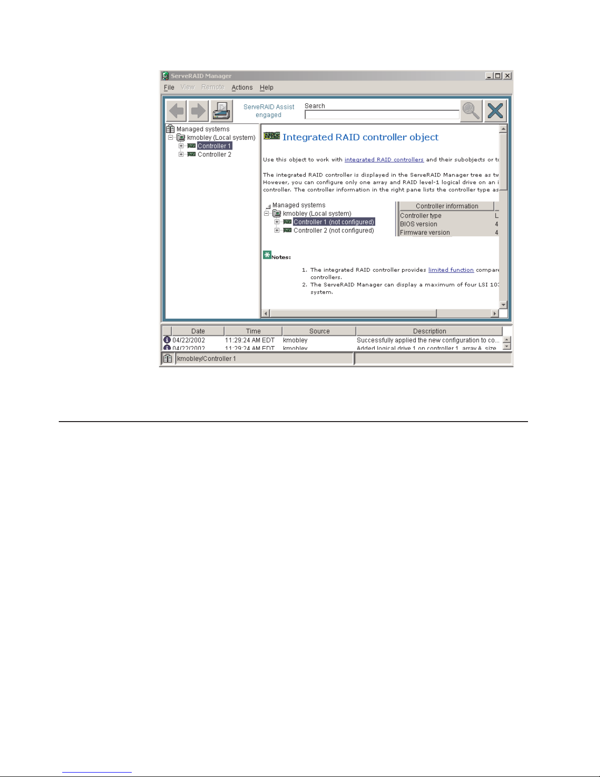
Figure 13. Hints and tips feature
Remote Supervisor Adapters
This section describes how to identify the Remote Supervisor Adapter, its features,
and prerequisites for setup. It also explains how to use the documentation
effectively and how to cable and configure a Remote Supervisor Adapter II-EXA or
a Remote Supervisor Adapter for use on an Advanced System Management (ASM)
network so that you can manage the server from a remote location. For more
detailed information, see the Remote Supervisor Adapter User’s Guide on the IBM
xSeries Documentation CD.
Identifying the Remote Supervisor Adapter
The server comes with either a Remote Supervisor Adapter or a Remote Supervisor
Adapter II-EXA installed. Before you can configure and use your Remote Supervisor
Adapter, you must identify which Remote Supervisor Adapter is installed. The
easiest way to identify the Remote Supervisor Adapter installed in the server is
visually. Use Figure 14 on page 33 and Figure 15 on page 33 to identify the
Remote Supervisor Adapter installed in the server:
32 xSeries 445 Type 8870: Hardware Maintenance Manual and Troubleshooting Guide
Page 43

External power
connector
Heartbeat LED
(amber)
Power LED
(green)
RSA II - EXA
breakout port
Video port
Ethernet activity LED
(green)
Ethernet link LED
(green)
10/100
Ethernet port
Figure 14. Remote Supervisor Adapter II-EXA connectors and LEDs
External power
connector
Error LED
(amber)
ASM interconnect
port
Ethernet activity LED
(green)
Ethernet link LED
(green)
Power LED
(green)
Management port
Figure 15. Remote Supervisor Adapter connectors and LEDs
After identifying the adapter, see “Setting up the Remote Supervisor Adapter II-EXA”
or “Setting up the Remote Supervisor Adapter” on page 44.
Setting up the Remote Supervisor Adapter II-EXA
This section describes features, setup requirements, and how to cable and
configure the Remote Supervisor Adapter II-EXA for use on an Advanced System
Management (ASM) network so that you can manage the server from a remote
location.
For more detailed information, see the Remote Supervisor Adapter II User’s Guide
on the IBM xSeries Documentation CD.
Remote Supervisor Adapter II-EXA features
The Remote Supervisor Adapter II-EXA provides the following:
v Seamless remote accelerated graphics
v Enhanced security features
v Continuous health monitoring and control
®
v Advanced Predictive Failure Analysis
v Automated Server Restart (ASR)
v Automatic notification and alerts
v Event logs that are time stamped, saved on the Remote Supervisor Adapter
II-EXA, and can be attached to e-mail alerts
v Server console redirection
v LAN and Advanced System Management (ASM) interconnect remote access
(PFA) support
10/100
Ethernet port
Chapter 2. Configuration 33
Page 44

v Simple Network Management Protocol (SNMP) trap support
v Domain Name System (DNS) and Dynamic Host Configuration Protocol (DHCP)
support
v Remote power control
v Capture operating-system-failure screen
v Remote firmware update and access to critical server settings
v Independent power, which enables around-the-clock access to the server even
when the server power is off
v Virtually attach remote diskette drive, CD-ROM drive, or disk image to server
Setup requirements
The following items are required to set up the Remote Supervisor Adapter II-EXA:
v Make sure you have an Internet connection. You will need an Internet connection
during the installation process to download software and firmware from the IBM
Support Web site. For information about how to download the Remote Supervisor
Adapter II-EXA files, see “Obtaining Remote Supervisor Adapter II-EXA software
and firmware” on page 37.
v Install the operating system on the server before you install the device drivers for
the Remote Supervisor Adapter II-EXA. For information about installing the
operating system, see the documentation that comes with the server.
v Remote Supervisor Adapter II-EXA device drivers. See Table 1 on page 23 for a
list of the supported operating systems.
Note: Not all versions of Red Hat Linux or SuSE Linux are supported for all
server models. To check if there is a supported Remote Supervisor
Adapter II-EXA device driver for the server model running your version of
Linux, go to http://www.ibm.com/pc/support/.
v The remote disk function requires the following software:
– Server (for the server operating system to support the remote disk): Microsoft
Windows 2000 with Service Pack 3 or above.
™
– Client: Microsoft Windows 2000 or above and the Java
1.4 Plug-in or later.
v To configure the remote alert recipients for Director over LAN or Director over
modem, the remote alert recipient must be an IBM Director-enabled server with
UM Server Extensions.
v The Remote Supervisor Adapter II supports the following Web browsers for
remote access. The Web browser that you use must be Java-enabled and must
support JavaScript™.
– Microsoft Internet Explorer 4.0 (with Service Pack 1), or later
– Netscape Navigator 4.72, or later (version 6.0 is not currently supported)
Notes:
1. Java plug-in version 1.4 or later is required.
2. The Remote Supervisor Adapter II Web interface does not support the
double-byte character set (DBCS) languages.
Support of HTTP version 1.0, or later
–
– Minimum display resolution of 800 x 600 pixels and 256 colors
The ASM Web interface and the ASM text-based interface do not support
Note:
the double-byte character set (DBCS) languages.
34 xSeries 445 Type 8870: Hardware Maintenance Manual and Troubleshooting Guide
Page 45

Cabling and configuring the Remote Supervisor Adapter II-EXA
Complete the following tasks to cable and configure the Remote Supervisor Adapter
II-EXA.
Note: After you initially configure the adapter, use the Web-based interface to
create a backup copy of the configuration. If you need to replace the adapter
in the future, you can restore the configuration and resume normal operation
more quickly. See the IBM Remote Supervisor Adapter II User’s Guide, on
the IBM xSeries Documentation CD for details.
Task 1. Cable the Remote Supervisor Adapter II-EXA.
Task 2. Get the Remote Supervisor Adapter software and firmware.
Task 3. Complete the setup of the Remote Supervisor Adapter II-EXA.
service, assistance, or additional information on the World Wide Web, see
For
Appendix A, “Getting help and technical assistance,” on page 299.
The RSA II-EXA breakout cable: The ASM breakout cable connects the Remote
Supervisor Adapter II-EXA to the ASM interconnect network, the server USB port,
and an external modem.
ASM RS-485
connector
USB connector
Management
connectors
Figure 16. RSA II-EXA breakout cable
RSA II-EXA breakout cable connections: The RSA II-EXA breakout cable is used
to provide the following connections:
v ASM Interconnect port
To connect the Remote Supervisor Adapter II-EXA to an ASM interconnect
network, connect a Category 3 or Category 5 cable to one of the ASM
Interconnect ports on the RSA II-EXA breakout cable. For more information, see
“Using the ASM interconnect network” on page 56.
v USB connector
To connect the Remote Supervisor Adapter II-EXA to the USB port on the server
for providing remote keyboard, video, and mouse control of the server, plug the
USB connector on the RSA II-EXA breakout cable in to a USB port on the server.
v Management port
To connect the Remote Supervisor Adapter II-EXA to a modem, connect the
modem to the management port connector on the RSA II-EXA breakout cable.
Note: Connecting a modem to the Remote Supervisor Adapter II-EXA provides
dial-out support only.
Chapter 2. Configuration 35
Page 46

Cable the Remote Supervisor Adapter II-EXA: This section provides the
information needed to cable the Remote Supervisor Adapter II.
Figure 17. Connect the RSA II-EXA breakout cable to the server
1. Connect the RSA II-EXA breakout cable (1) to the RSA II-EXA breakout port
(2) on the server.
2. Connect the video cable from your video device to the video port on the Remote
Supervisor Adapter.
3. Plug the USB connector on the RSA II-EXA breakout cable in to one of the USB
ports on the rear of the server.
ASM RS-485
connector
USB connector
Management
connectors
Figure 18. RSA II-EXA breakout cable
4. Complete the following steps to connect the Remote Supervisor Adapter II-EXA
to the LAN:
a. Connect one end of a Category 3 or Category 5 Ethernet cable to the
Ethernet connector on the Remote Supervisor Adapter II-EXA. Connect the
other end of the Ethernet cable to your network.
b. Check the Remote Supervisor Adapter II-EXA Ethernet link and activity
LEDs. The location of the LEDs are shown in the following illustration.
36 xSeries 445 Type 8870: Hardware Maintenance Manual and Troubleshooting Guide
Page 47

External power
connector
Heartbeat LED
(amber)
Power LED
(green)
RSA II - EXA
breakout port
Video port
Ethernet activity LED
(green)
10/100
Ethernet port
Figure 19. Remote Supervisor Adapter II-EXA connectors
v External power connector: This connector is used to connect the
Remote Supervisor Adapter II-EXA to an external power source.
v Heartbeat LED: This amber LED flashes continuously to indicate that
there is activity on the Remote Supervisor Adapter II-EXA.
v RSA II-EXA breakout port: The RSA II-EXA breakout cable is connected
to this port to provide two serial (communication) ports, one USB port,
and one RS-485 port with two connectors.
v Ethernet activity LED: When the LED is green, there is activity on the
Ethernet LAN.
v Ethernet link LED: When the LED is green, the link is active.
v 10/100 Ethernet port: Ethernet signal cables are connected to the
Ethernet port.
v Video port: Connect the signal cable for a monitor to this port.
Ethernet link LED
(green)
Important: When the Remote Supervisor Adapter II-EXA is installed in
place of the Remote Supervisor Adapter, you must connect
the monitor or console switch to this video port. The
integrated video controller on the server is disabled for
models with a Remote Supervisor Adapter II-EXA installed.
v Power LED: This green LED comes on and stays on when you plug in
the server.
c. Continue with “Obtaining Remote Supervisor Adapter II-EXA software and
firmware” and “Completing the setup” on page 39.
See the IBM Remote Supervisor Adapter II User’s Guide on the IBM xSeries
Note:
Documentation CD for detailed information on how to manage the server
remotely using the Web-based user interface.
Obtaining Remote Supervisor Adapter II-EXA software and firmware: Before
you can continue the configuration of the Remote Supervisor Adapter II-EXA, you
must download software and firmware from the IBM Support Web site. This section
describes how to download the files from the Web site. Which files you need to
download depends on your operating system.
Note: Changes are made periodically to the IBM Support Web site to provide
timely customer information and better navigation. The search methods in
the following procedures are suggestions. Yo u might need to modify the
search process depending on the Web page design.
Chapter 2. Configuration 37
Page 48

For Microsoft Windows 2000: If the server in which the Remote Supervisor
Adapter II-EXA is installed is running the Microsoft Windows 2000 operating system,
you will need to download one file, which contains the following software and
firmware:
v Software and firmware installation instructions
v Video adapter basic input/output system (BIOS) update
v IBM Eserver xSeries BIOS update with support for the Remote Supervisor
Adapter II-EXA
v Diagnostics code update
v Remote Supervisor Adapter II-EXA device drivers
v Remote Supervisor Adapter II-EXA firmware code update
v Integrated system management processor (ISMP) update
v Video device driver
v Advanced Settings Utility program
The software and firmware files that you need are contained in one system service
package for Windows installation kit. Complete the following steps to locate and
download the package file.
1. Go to http://www.ibm.com/pc/support/.
2. In the left navigation pane, click Search PC support.
3. In the “Search PC support” window, under Additional search options, in the
Restrict to this document type field, select Downloads and drivers.
4. In the Restrict to this brand field, select Servers.
5. Wait for the page to automatically refresh; then, in the Restrict to this family
field, select the server model.
6. Wait for the page to automatically refresh; then, in the Enter search terms
field, type "system service package". (Do not use the Search field.)
7. Click Search.
8. Select the system service package that corresponds to the server model and
the operating system that is running on the server in which the Remote
Supervisor Adapter II is installed. The file you download will be in *.exe format.
9. Click the file link to download the system service package to d:/ibmssp, where
d is the hard disk drive letter. (Create the directory if necessary.)
10. Browse the d:/ibmssp directory and double click the *.exe file to extract the
packaged files. Extract the files into the d:/ibmssp directory.
11. See the readme.txt file that is extracted into the d:/ibmssp directory for a list of
the file names and their descriptions.
12. To ensure correct software installation, follow the detailed installation
instructions in Remote Supervisor Adapter II Installation Instructions for
Windows Users, which is in Portable Document Format (PDF) in the d:/ibmssp
directory. Then, continue with “Completing the setup” on page 39.
SuSE Linux and Red Hat Linux: If the server in which the Remote Supervisor
For
Adapter II-EXA is installed is running the Red Hat Linux or SuSE Linux operating
system, you will need to download one file, which contains the following software
and firmware:
v Software and firmware installation instructions
v Video adapter basic input/output system (BIOS) update
v IBM Eserver xSeries BIOS update with support for the Remote Supervisor
Adapter II-EXA
38 xSeries 445 Type 8870: Hardware Maintenance Manual and Troubleshooting Guide
Page 49

v Diagnostics code update
v Remote Supervisor Adapter II-EXA device drivers
v Remote Supervisor Adapter II-EXA firmware code update
v Advanced Settings Utility program
The software and firmware files that you need are contained in one system service
package for Linux installation kit. Complete the following steps to locate and
download the package file:
1. Go to http://www.ibm.com/pc/support/.
2. In the left navigation pane, click Search PC support.
3. In the “Search PC support” window, under Additional search options, in the
Restrict to this document type field, select Downloads and drivers.
4. In the Restrict to this brand field, select Servers.
5. Wait for the page to automatically refresh; then, in the Restrict to this family
field, select the server model.
6. Wait for the page to automatically refresh; then, in the Enter search terms
field, type "system service package". (Do not use the Search field.)
7. Click Search.
8. Select the system service package that corresponds to the server model and
the operating system that is running on the server in which the Remote
Supervisor Adapter II is installed. The file you download will be in *.tgz format.
9. Click the file link to download the system service package.
10. From a command-line prompt, type "tar -xvfz filename.tgz", where filename
is the name of the file you downloaded. This command will create a directory
named ibmssp and extract the files to it.
11. See the readme.txt file that is extracted into the ibmssp directory for a list of
the file names and their descriptions.
12. To ensure correct software installation, follow the detailed installation
instructions in Remote Supervisor Adapter II Installation Instructions for Linux
Users, which is in Portable Document Format (PDF) in the ibmssp directory.
Then, continue with “Completing the setup.”
Completing
Remote Supervisor Adapter II-EXA:
1. If you plan to configure Simple Network Management Protocol (SNMP) traps on
the Remote Supervisor Adapter II-EXA, install and compile the management
information base (MIB) on your SNMP manager. The MIB supports SNMP traps.
The MIB is available on the IBM Support Web site. For more information, see
“Obtaining Remote Supervisor Adapter II-EXA software and firmware” on page
37.
2. If you did not restart the server after installing the Remote Supervisor Adapter
II-EXA device drivers, restart the server now.
3. See the IBM Remote Supervisor Adapter II User’s Guide on IBM xSeries
Documentation CD for detailed instructions for completing the configuration of
the Remote Supervisor Adapter II-EXA, including the following features:
v Defining the login IDs and passwords
v Selecting the events that will receive alert notification
the setup: Complete the following steps to complete the setup of the
Chapter 2. Configuration 39
Page 50

v Monitoring remote server status using the Remote Supervisor Adapter II-EXA
Web interface
v Controlling the server remotely
v Virtually attaching a remote diskette drive, CD-ROM drive, or disk image to
the server
If you want to set up an ASM interconnect network and have not already done so,
go to “Configuring and connecting to the ASM interconnect network.” If you do not
want to set up an ASM interconnect network, your configuration is now complete.
Configuring and connecting to the ASM interconnect network
This section includes information about how to configure and connect the server to
function within an Advanced System Management (ASM) interconnect network.
Overview: Yo u can connect system-management processors and adapters
together to form an Advanced System Management (ASM) interconnect network.
System-management processors and adapters are Remote Supervisor Adapter
II-EXAs, Remote Supervisor Adapter IIs, Remote Supervisor Adapters, ASM
processors, ASM PCI adapters, and integrated system management processors
(ISMPs). These system-management processors and adapters are also known as
service processors.
An ASM interconnect network provides two levels of functionality. First, the ASM
interconnect network enables you to control and to configure settings for the servers
in which other system-management processors and adapters reside. Second, the
ASM interconnect network enables other system-management processors and
adapters to use the resources (Ethernet or modem) of other Remote Supervisor
Adapter II-EXAs, Remote Supervisor Adapters IIs, Remote Supervisor Adapters,
ASM processors (modems only), and ASM PCI adapters in the ASM interconnect
network for sending alerts. This interconnect network is used when
system-management processors or adapters cannot send an alert and must forward
the information to another system-management processor or adapter to send the
alert.
Planning and cabling your ASM interconnect network: To support the most
recent ASM features, a Remote Supervisor Adapter II-EXA must be the main
gateway to your ASM interconnect network if the network also includes servers with
Remote Supervisor Adapters, ASM PCI adapters, ASM processors, or ISMPs. The
Remote Supervisor Adapter II-EXA forwards the ASM information generated by the
servers attached to the ASM interconnect network to other servers on your Ethernet
network or that are attached through a modem. The connected ASM processors,
ASM PCI Adapters, and ISMPs are managed through the user interface and Web
browser access of the Remote Supervisor Adapter II.
Before cabling the ASM interconnect network, review the following information:
v You must connect an RSA II-EXA breakout cable to the Remote Supervisor
Adapter II-EXA.
v You must connect an ASM interconnect module to a Remote Supervisor Adapter.
v The cables in an ASM interconnect network are hot-swappable.
v Make sure that the firmware for the Remote Supervisor Adapter II-EXA, Remote
Supervisor Adapter, ASM processor, ASM PCI adapter, and ISMP are at the
latest level.
v The servers in an ASM interconnect network are referred to by their assigned
names, not by their positions in the rack cabinet.
40 xSeries 445 Type 8870: Hardware Maintenance Manual and Troubleshooting Guide
Page 51

An ASM interconnect network can have up to 24 RS-485 connections, depending
on the configuration. The connections can include Remote Supervisor Adapter
II-EXAs, Remote Supervisor Adapter IIs, Remote Supervisor Adapters, ASM
processors, ASM PCI adapters, and ISMPs. Use the following information to
determine the number of servers and connections that you can have on your ASM
interconnect network:
v Each Remote Supervisor Adapter II-EXA, Remote Supervisor Adapter II, Remote
Supervisor Adapter, ASM processor, ASM PCI adapter, and ISMP in a server that
is connected to the network uses one connection. For example, if a server that is
connected to the network has a Remote Supervisor Adapter and an integrated
ASM processor, the server uses two connections on the network.
v The network must include at least one server with a Remote Supervisor II-EXA,
Remote Supervisor Adapter II, or Remote Supervisor Adapter (either installed as
an option or preinstalled in the server).
v On an ASM interconnect network, one ASM processor or one ASM PCI adapter
can communicate with 11 RS-485 connections. These connections must be to
ASM processors, ASM PCI adapters, Remote Supervisor Adapters, Remote
Supervisor Adapter II-EXAs, or Remote Supervisor Adapter IIs. The ASM
processor and ASM PCI adapter cannot communicate with ISMPs.
v If your existing ASM interconnect network has 12 RS-485 connections that
include only ASM processors, ASM PCI adapters, and at least one Remote
Supervisor Adapter or Remote Supervisor Adapter II, you can also add up to 12
ISMP-based servers to this same network. The Remote Supervisor Adapter on
this network will communicate with all 23 RS-485 connections; however, an ASM
processor or ASM PCI adapter on this network will communicate with only the 11
non-ISMP RS-485 connections. The ASM processor and ASM PCI adapter will
not recognize the ISMPs, but the ISMPs can reside on the same ASM
interconnect network.
v Make sure that the ASM interconnect network is set up as a bus, not as a ring.
You must connect the servers to the ASM interconnect network in a series, with
terminated beginning and end points. Be sure to use the RS-485 terminator
plugs. For more information, see “Using the RS-485 terminator plugs on
interconnected servers.”
v Make sure that the total combined length of all Ethernet cables connecting the
servers in the ASM interconnect network does not exceed 91 m (300 ft).
the RS-485 terminator plugs on interconnected servers: The Remote
Using
Supervisor Adapter II-EXA comes with two RS-485 terminator plugs. To ensure
successful RS-485 communication on your ASM interconnect network, you must
install the terminator plugs in the open connectors at each end of the RS-485 bus.
The illustrations in “ASM interconnect network configuration examples” on page 42
can help you determine where to put the RS-485 terminator plugs on your ASM
interconnect network.
Forwarding alerts: Remote Supervisor Adapters, ASM PCI adapters, ASM
processors, and ISMPs that are connected to an ASM interconnect network share
resources and system-management information. This section provides information
about how alerts are forwarded in the ASM interconnect network.
During normal operation, each Remote Supervisor Adapter, ASM processor, ASM
PCI adapter, and ISMP on the ASM interconnect network communicates with the
other processors and adapters on the network. Processors or adapters that have a
modem or Ethernet connection notify the other processors and adapters that these
communications resources are available for use by other servers on the ASM
interconnect network. These resources are then used as ASM interconnect network
Chapter 2. Configuration 41
Page 52

resources, enabling Remote Supervisor Adapters, ASM processors, ASM PCI
adapters, and ISMPs on the ASM interconnect network to send alerts using a
modem or the network, even if they do not have a modem or network connection
physically attached.
Note: ISMPs can use the communications resources of a Remote Supervisor
Adapter, Remote Supervisor Adapter II-EXA, or Remote Supervisor Adapter
II only.
When alerts are generated, they are forwarded to the Remote Supervisor Adapter
II-EXA, Remote Supervisor Adapter II, Remote Supervisor Adapter, ASM processor,
or ASM PCI adapter on the ASM interconnect network that has the communication
resources to forward the alert. If no system on the ASM interconnect network meets
the requirements, the alert is set for transmission if the connection type is
configured or becomes available later.
If multiple modems or network connections exist in the ASM interconnect network,
you cannot specify which system will receive an alert or which will use its modem or
network connection to forward the alert. If an alert is forwarded to a Remote
Supervisor Adapter II-EXA, Remote Supervisor Adapter II, Remote Supervisor
Adapter, ASM processor, or ASM PCI adapter that is unable to deliver the alert (for
example, the modem it is configured to use has failed or the network cannot resolve
the destination IP address), the processor or adapter attempts to forward the alert
to another system on the ASM interconnect network that has the communication
resources to forward the alert.
Alerts are typically sent only once (per connection type), but an alert is forwarded to
another interconnect device if the resources exist on other interconnect devices in
the network. For example, on a three ASM processor network where ASM
processor 1 generates a modem alert, but does not have a modem and the two
other ASM servers with ASM processors have modems connected to them, the
following might occur:
If ASM processor 1 generates an alert and the modem is unplugged from ASM
processor 2 45 seconds or less prior to ASM processor 1 generating the alert, ASM
processor 1 forwards the alert to ASM processor 2 having previously determined
that ASM processor 2 had an available modem (which is now no longer available).
When ASM processor 2 receives the forwarded alert, knowing its modem is not
available, it determines that a modem is attached to ASM processor 3, and forwards
the alert to ASM processor 3. Therefore, depending upon the time frame (45
seconds) within which a resource (modem) fails, the alert might be forwarded
multiple times until a device on the interconnect network can send the alert.
ASM interconnect network configuration examples: The illustrations in this
section show sample ASM interconnect network configurations.
In the following example, an Ethernet cable connects the remote system
management administrator’s system to the Remote Supervisor Adapter II-EXA that
is installed in an xSeries 445. In this case, the xSeries 445 uses the LAN
connection to forward system-management data generated by the other servers in
the ASM interconnect network to the remote system-management administrator.
42 xSeries 445 Type 8870: Hardware Maintenance Manual and Troubleshooting Guide
Page 53

Remote system
management
administrator's system
Ethernet
Remote
Supervisor
Adapter II - EXA
xSeries 445
xSeries 445
RS-485
terminator plug
Figure 20. ASM interconnect network Ethernet configuration
Remote
Supervisor
Adapter
ASM
Interconnect
module
xSeries 445
RS-485
terminator plug
In the following example, a Remote Supervisor Adapter II-EXA is installed in an
xSeries 445, and creates an interconnect network with the other xSeries 445
servers which have a Remote Supervisor Adapter installed. A modem is connected
to the serial connector of the Remote Supervisor Adapter II-EXA (on one end of the
ASM breakout cable), a second modem is connected to the management port of
the Remote supervisor Adapter in the server connected to the end of the ASM
interconnect network, and a modem is connected to the remote
system-management administrator’s system.
Note: For information about connecting a modem to the management port on an
xSeries 445, see the documentation that comes with the server.
Chapter 2. Configuration 43
Page 54

Remote system
management
administrator's system
Modem
Dial-out
only
Modem
xSeries 445
xSeries 445
ASM
Interconnect
module
Management
port
Note: The ASM Interconnect module is connected to the RS-485 port on the
back panel of the Remote Supervisor Adapter in each server.
RS-485
terminator plug
Figure 21. ASM interconnect network modem configuration
Modem
xSeries 445
RS-485
terminator plug
Setting up the Remote Supervisor Adapter
This section describes features, setup requirements, and how to cable and
configure the Remote Supervisor Adapter for use on an Advanced System
Management (ASM) network so that you can manage the server from a remote
location.
Note: The information in this section is intended for use with the Remote
Supervisor Adapter, not the Remote Supervisor Adapter II-EXA. For
information on setting up and configuring a Remote Supervisor Adapter
II-EXA go to “Setting up the Remote Supervisor Adapter II-EXA” on page 33.
For more detailed information, see the Remote Supervisor Adapter User’s Guide on
the IBM xSeries Documentation CD.
Remote Supervisor Adapter features
Standard features of the Remote Supervisor Adapter are as follows:
v Continuous health monitoring and control
v Advanced Predictive Failure Analysis (PFA)
v Configurable notification and alerts
44 xSeries 445 Type 8870: Hardware Maintenance Manual and Troubleshooting Guide
Page 55

v Event logs that are time-stamped, saved in nonvolatile memory, and can be
attached to e-mail alerts
v Remote graphics console redirection
v LAN, serial, and Advanced System Management (ASM) interconnect remote
access
v Point-to-point protocol (PPP) support
v Simple Network Management Protocol (SNMP)
v Domain Name System (DNS) and Dynamic Host Configuration Protocol (DHCP)
support
v Remote power control
v Microsoft Windows NT and Windows 2000 blue-screen capture
v Remote firmware update and access to critical server settings
v Optional, independent power, which enables around-the-clock access to the
server, even if the server is powered off
Setup requirements
Before you set up the Remote Supervisor Adapter, you must download to a
diskette, the DOS Remote Supervisor Utility program from
http://www.ibm.com/pc/support/.
Perform the following before you set up the Remote Supervisor Adapter:
v Install the operating system on the server, using ServerGuide and the
documentation that comes with the operating system.
v Install the agent component of UM Server Extensions to use the following
Advanced System Management (ASM) Web interface features:
– Shutdown O/S and then Power Off Server
– Shutdown O/S and then Restart Server
Server Extensions is on the system-management software CD that comes
UM
with the server. For information about installing the agent component, see the
documentation that comes with the system-management CD.
v To configure the remote alert recipients for Director over LAN or Director over
modem, the remote alert recipient must be an IBM Director-enabled server with
UM Server Extensions.
v If you want to use a Web browser to access the Remote Supervisor Adapter
remotely, the following software is required:
– Microsoft Internet Explorer 4.0 (with Service Pack 1), or later
– Netscape Navigator 4.72, or later (version 6.0 is not currently supported)
– Java enabled Web browser (See your browser documentation or online Help
for instructions about enabling its Java support.)
– Support for JavaScript 1.2, or later (See your browser documentation or online
Help for instructions about enabling its JavaScript support.)
– Support of HTTP version 1.0, or later
– Minimum display resolution of 800 x 600 pixels and 256 colors
Note:
The ASM Web interface and the ASM text-based interface do not support
the double-byte character set (DBCS) languages.
Chapter 2. Configuration 45
Page 56

Cabling and configuring the Remote Supervisor Adapter
Complete the following tasks to cable and configure the Remote Supervisor
Adapter.
Note: After you initially configure the adapter, use the Web-based interface to
create a backup copy of the configuration. If you need to replace the adapter
in the future, you can restore the configuration and resume normal operation
more quickly. See the IBM Remote Supervisor Adapter User’s Guide, on the
IBM xSeries Documentation CD for details.
Task 1. Connect the Ethernet and management port cables. See “Cabling
the Ethernet LAN port and management port.”
Task 2. Perform the initial configuration to enable remote access to the
Remote Supervisor Adapter. So that you can:
v Configure the Ethernet port
v Configure the management (COM) port
v Set up the point-to-point protocol
See “Enabling remote access to the adapter” on page 48.
Task 3. Configure the remote-control password to enable the ASM Web
interface remote control features. See “Configuring the remote
control password” on page 55.
Task 4. Install the ASM device drivers. See “Installing Advanced System
Management device drivers” on page 53.
service, assistance, or additional information on the World Wide Web, see
For
Appendix A, “Getting help and technical assistance,” on page 299.
Cabling the Ethernet LAN port and management port: This section describes
how to cable the Remote Supervisor Adapter. Yo u can manage the server remotely
through the Remote Supervisor Adapter using one of the user interfaces and one of
the connection methods that are described in Table 2. Select the interface method
you want to use to perform remote management; then, perform the indicated
cabling procedure.
If you plan to set up an ASM interconnect network, before you begin cabling the
server, see “Using the ASM interconnect network” on page 56 for instructions about
cabling the ASM interconnect port and setting up the network. You might want to
review the information in “ASM interconnect network configuration examples” on
page 42 before you connect the cables. Then, return to these instructions to start
the cabling procedures.
Table 2. Cabling tasks to enable remote access to the Remote Supervisor Adapter
User interface to Remote
Supervisor Adapter
ASM Web interface using
HTTP
Text-based user interface
using the Telnet protocol
Connection to Remote
Supervisor Adapter
LAN using the Ethernet port “Cabling the Ethernet LAN port”
For the cabling procedure,
see:
on page 47
46 xSeries 445 Type 8870: Hardware Maintenance Manual and Troubleshooting Guide
Page 57

Table 2. Cabling tasks to enable remote access to the Remote Supervisor
Adapter (continued)
User interface to Remote
Supervisor Adapter
Text-based user interface
using a modem or a null
Connection to Remote
Supervisor Adapter
For the cabling procedure,
see:
Management (COM) port “Cabling the management
(COM) port” on page 48
modem
ASM Web interface using
point-to-point protocol
(PPP)
Text-based user interface
using the Telnet protocol
over PPP
Cabling the Ethernet LAN port: Complete the following steps to attach the Ethernet
cables.
Attention: To avoid damage to the Ethernet connector on the Remote Supervisor
Adapter, do not connect the ASM Interconnect module to the Ethernet port.
1. Connect one end of a Category 3 or Category 5 Ethernet cable to the Ethernet
port on the Remote Supervisor Adapter. Connect the other end of the Ethernet
cable to the network.
2. Check the Ethernet LEDs to ensure that the network connection is working. The
following illustration shows the location of the LEDs.
External power
connector
Error LED
(amber)
ASM interconnect
port
Ethernet activity LED
(green)
Ethernet link LED
(green)
Figure 22. Remote Supervisor Adapter connectors
v External power connector (not supported) - This connector is not
supported on this server.
v Error LED - This amber LED is lit when a system management error has
occurred.
v ASM interconnect port - Signal cables for managing expansion module
resources are connected to this port.
v Ethernet activity LED: When the LED is green there is activity on the
Ethernet LAN.
v Ethernet link LED: When the LED is green the link is active.
v 10/100 Ethernet port - Ethernet Signal cables are connected to the Ethernet
port.
v Management port - Connect a serial cable to this port to enable system
management through a modem, or connect a null modem cable to enable
system management through a workstation or laptop computer.
Power LED
(green)
Management port
10/100
Ethernet port
Chapter 2. Configuration 47
Page 58

v Power LED - This green LED goes on and stays on when you plug in the
server.
you want to use the management port connection, continue with “Cabling the
If
management (COM) port” on page 48; otherwise, go to “Configuring the
adapter.”
Cabling
the management (COM) port: To cable the management (COM) port,
connect a modem or null modem cable to the management port on the Remote
Supervisor Adapter.
Continue with “Configuring the adapter.”
Configuring the adapter: This section describes how to enable remote access to
the Remote Supervisor Adapter and install ASM device drivers.
These procedures assume that you have an operational keyboard and pointing
device attached to the server.
Enabling remote access to the adapter: The Remote Supervisor Adapter requires
configuration to enable remote access through either the Ethernet port or the
management port. From Table 3, select the interface method that you want to use
to perform remote management; then, perform the indicated configuration
procedure.
Note: For detailed information about using the ASM Web interface and the
text-based user interface, see the Remote Supervisor Adapter User’s Guide
on the IBM xSeries Documentation CD.
Table 3. Configuration tasks to enable remote access to the Remote Supervisor Adapter
User interface to Remote
Supervisor Adapter
ASM Web interface using
HTTP
Text-based user interface
Connection to Remote
Supervisor Adapter
For the configuration
procedure, see:
LAN using the Ethernet port “Configuring the Ethernet
settings for Web-based remote
access”
using the Telnet protocol
Text-based user interface
using a modem or a null
modem
ASM Web interface using
point-to-point protocol
Management (COM) port “Configuring the management
port for text-based remote
access” on page 50 and “Setting
up point-to-point protocol” on
page 52
(PPP)
Text-based user interface
using the Telnet protocol
over PPP
Configuring the Ethernet settings for Web-based remote access: If you have an
accessible, active, and configured dynamic host configuration protocol (DHCP)
server on the network, the hostname, IP address, gateway address, subnet mask,
and DNS server IP address are set automatically. You do not need to perform
further configuration tasks to enable the Ethernet connection because the default
value for the DHCP Setting field is Enabled. If you need to configure the
management port, go to “Configuring the management port for text-based remote
access” on page 50; otherwise, go to “Installing Advanced System Management
device drivers” on page 53.
48 xSeries 445 Type 8870: Hardware Maintenance Manual and Troubleshooting Guide
Page 59

If you do not have a DHCP server on the network, complete the following steps to
configure the Ethernet settings.
1. With the server turned off, insert the diskette with the downloaded utility
program into the diskette drive; then, turn on the server. The utility starts
automatically, displaying the Remote Supervisor Utility window.
2. Use the Up Arrow and Down Arrow keys (↑ and ↓) to select Configuration
Settings; then, press Enter. The Configuration Settings window opens.
3. Use the arrow keys to select Ethernet Settings; then, press Enter.
The Ethernet Settings window opens, as shown in the following illustration.
Note: The values in the window are only examples; your settings might be
different.
Figure 23. Ethernet Settings window with Web-based remote values
4. Use the arrow keys to navigate to each field. Your system administrator can
provide the information for the following fields:
Network Interface
The default value is Enabled; verify that it is still set to Enabled.
IP Address
Type the IP address of the Remote Supervisor Adapter.
Subnet Mask
Type the subnet mask used by the Remote Supervisor Adapter. The
default value is 255.255.255.0.
Gateway
Type the IP address of the gateway.
Host Name
Type the host name of the Remote Supervisor Adapter. The default
host name is ASMA<burned-in MAC address>.
For detailed information about the Ethernet settings, see the Remote
Supervisor Adapter User’s Guide on the IBM xSeries Documentation CD.
5. Change the DHCP Setting field to Disabled. The default value is Enabled.
6. Press F6 to apply the change.
Chapter 2. Configuration 49
Page 60

7. Press Esc. After the Warning window opens, press Enter to restart the Remote
Supervisor Adapter.
8. Press Esc to return to the Configuration Settings window.
If you need to configure the management port, go to “Configuring the
management port for text-based remote access.”
9. Press Esc to return to the Utility program main window.
10. Use the arrow keys to select Exit Utility from the menu or press Esc to close
the Utility program.
11. Remove the diskette from the server. The server restarts automatically.
12. If you also want to configure the management port, continue with “Configuring
the management port for text-based remote access.” Otherwise, go to
“Installing Advanced System Management device drivers” on page 53.
Configuring
the management port for text-based remote access: Complete the
following steps to configure the Remote Supervisor Adapter management port for
access using a modem or null modem. If you completed the procedure for
configuring the Ethernet port and the Configuration Settings window is open, go to
step 3
1. With the server turned off, insert the diskette with the downloaded utility
program into the diskette drive; then, turn on the server. The utility starts
automatically, displaying the Remote Supervisor Utility window.
2. Use the Up Arrow and Down Arrow keys (↑ and ↓) to select Configuration
Settings; then, press Enter.
The Configuration Settings window opens.
3. Use the arrow keys to select Modem Settings; then, press Enter.
The Modem Settings window opens, as shown in the following illustration.
Note: The values in the window are only examples; your settings might be
different.
Figure 24. Ethernet Settings window with text-based remote access values
50 xSeries 445 Type 8870: Hardware Maintenance Manual and Troubleshooting Guide
Page 61

4. Verify the following management port values:
Baud Rate
The default is 57600. Make sure that the baud rate matches the baud
rate of the device you are connecting to the management port on the
Remote Supervisor Adapter.
Dedicated to ASM
The default is Disabled. If you are using point-to-point protocol (PPP),
set this field to Enabled. If the value in this field is Enabled when the
server is restarted, the management port remains dedicated to system
management and is not returned to the operating system.
You can dedicate the integrated management port on the Remote
Supervisor Adapter to system management or share it with the
operating system. If the management port is dedicated to system
management, it serves only the Remote Supervisor Adapter and is
always available for dial-in or dial-out alerting purposes. Yo u cannot
view the port using the operating system or any application.
Note: To use this management port, you must first install the ASM
device drivers as described in “Installing Advanced System
Management device drivers” on page 53.
If the management port is shared with the operating system, it is
dedicated to the Remote Supervisor Adapter only while the server is
turned off or during POST. The port is returned to the operating system
after POST completes. You can view the port using the operating
system or any application. The Remote Supervisor Adapter takes over
the port from the operating system only when information about a
critical event is received. The Remote Supervisor Adapter dials out and
transmits an alert and keeps the port dedicated until the server is
restarted. The port is no longer available to the operating system or
applications.
Parity The default is None.
Stop Bits
The default is 1.
The data bits value is preset to 8 and cannot be changed.
Note:
For detailed information about the management port and modem settings, see
the Remote Supervisor Adapter User’s Guide on the IBM xSeries
Documentation CD.
5. If you made changes to the management port settings, press F6 to apply the
change.
6. Press Esc to return to the Configuration Settings window.
you need to set up point-to-point protocol, go to “Setting up point-to-point
If
protocol” on page 52.
7. Press Esc to return to the Utility program main window.
8. Use the arrow keys to select Exit Utility from the menu, or press Esc to close
the Utility program.
9. Remove the diskette from the diskette drive. The Remote Supervisor Adapter
restarts automatically.
10. Continue with “Setting up point-to-point protocol” on page 52.
Chapter 2. Configuration 51
Page 62

Setting up point-to-point protocol: The Remote Supervisor Adapter management
port supports point-to-point protocol (PPP). PPP enables TCP/IP communication
over the management port, which enables Web-based management and Telnet
sessions over a modem. To set up PPP, complete the following steps. If you
completed the procedure for configuring the management port and the
Configuration Settings window is open, go to step 3 on page 52.
1. With the server turned off, insert the downloaded utility program into the
diskette drive; then, turn on the server. The utility starts automatically,
displaying the Remote Supervisor Utility window.
2. Use the Up Arrow and Down Arrow keys (↑ and ↓) to select Configuration
Settings; then, press Enter.
The Configuration Settings window opens.
3. Use the arrow keys to select PPP Settings; then, press Enter.
The PPP Settings window opens, as shown in the following illustration.
Note: The values in the window are only examples; your settings might be
different.
Figure 25. Ethernet Settings window setting up point-to-point protocol
4. Use the arrow keys to navigate to each field. Verify the values in the following
fields:
Network Interface
IP Address
Subnet Mask
Line Type
Remote IP Address
52 xSeries 445 Type 8870: Hardware Maintenance Manual and Troubleshooting Guide
The default is Disabled. Change this field to Enabled.
The default value is 192.96.1.1. Yo u can use the default value or
another value, but the server must be able to establish a connection to
that address. The default IP address (local and remote) is easily
reconfigurable.
The default value is 255.255.255.255.
The value is set to PPP.
The default value is 192.96.1.2.
Page 63

Authentication Protocol
The default is CHAP then PAP. Make sure that the value in this field
matches your client settings.
For detailed information about the PPP settings, see the information about
configuring PPP access over a management port in the Remote Supervisor
Adapter User’s Guide on the IBM xSeries Documentation CD.
5. Press F6 to apply the changes.
6. Press Esc. After the Warning window opens, press Enter to restart the Remote
Supervisor Adapter.
7. Press Esc to return to the Configuration Settings window. If you need to
configure the management port, go to “Configuring the management port for
text-based remote access” on page 50.
8. Press Esc to return to the Utility program main window.
9. Use the arrow keys to select Exit Utility from the menu or press Esc to close
the Utility program.
10. Remove the diskette from the diskette drive. The server restarts automatically.
11. Continue with “Installing Advanced System Management device drivers.”
Installing
Advanced System Management device drivers: You must install the ASM
device drivers for the server. The device drivers enable communication between the
Remote Supervisor Adapter and the server in which it is installed. You can obtain
the most current device drivers from http://www.ibm.com/pc/support.
The following sections describe the procedure for installing the ASM device drivers
for the server, depending on your operating system.
Notes:
1. If you are installing device drivers manually, note the following requirements:
v Make sure that the operating system is installed on the server before you
install the ASM device drivers. For information about installing the operating
system, see the documentation that comes with the operating system.
v Before installing the ASM device drivers for the Remote Supervisor Adapter,
stop any system-management application.
If you are using ServerGuide to install device drivers and your operating system
2.
is Windows 2000, ServerGuide installs the ASM device drivers automatically.
v Windows 2000: Continue with “Installing Windows 2000 ASM device drivers”
v Windows NT: Go to “Installing Windows NT ASM device drivers” on page 54.
After you install the ASM device drivers, go to “Configuring the remote control
password” on page 55 to set the remote control password.
Installing Windows 2000 ASM device drivers: To install the ASM device drivers for
Windows 2000, complete the following steps.
Notes:
1. Do not use the Hardware Wizard to install the drivers. If the Hardware Wizard
starts itself for the installation of any System Management Driver hardware, exit
the Hardware Wizard by selecting Cancel.
2. If IBM Netfinity
stop the system-management application before proceeding.
®
Director, IBM Director, or UM Services is running on the server,
Chapter 2. Configuration 53
Page 64

Complete the following steps to manually install the Windows 2000 ASM device
drivers.
1. Open a command prompt.
2. If you are installing from a diskette, type: a:\WIN2000\SETUP, where a is the drive
letter of the diskette drive.
3. If you are installing from a CD, type: d:\DD\WIN2000\SETUP, where d is the drive
letter of the DVD-ROM drive.
4. Follow the directions that display on the screen.
5. Go to “Configuring the remote control password” on page 55.
Installing
Windows NT ASM device drivers: Select one of the following methods to
install the ASM device drivers for Windows NT:
v Non-interactive
The non-interactive method for installing the ASM device drivers accepts the
default values for any window prompts that appear. You are prompted to respond
only if an error occurs during installation.
v Interactive
The normal (interactive) method for installing the ASM device drivers prompts
you with instructions and waits for you to respond before continuing with the
installation.
If IBM Netfinity Director, IBM Director, UM Services, or IBM Netfinity
Note:
Manager is running on the server, stop the system-management application
before proceeding.
the non-interactive method: Complete the following steps to use the
Using
non-interactive method.
1. Open a Windows NT command prompt; then, type one of the following
commands:
v If the installation is from a diskette, type:
a:\NT\SETUP -q
(where a is the drive letter assigned to the diskette drive).
Press Enter.
v If the installation is from a CD, type:
d:\DD\NT\SETUP -q
(where d is the drive letter assigned to the DVD-ROM drive).
Press Enter.
Follow the instructions that appear in the window.
2.
3. Go to “Configuring the remote control password” on page 55.
54 xSeries 445 Type 8870: Hardware Maintenance Manual and Troubleshooting Guide
Page 65

Using the interactive method: Complete the following steps to use the interactive
method.
1. Open a Windows NT command prompt; then, type one of the following
commands:
v If the installation is from a diskette, type:
a:\NT\SETUP
(where a is the drive letter assigned to the diskette drive).
Press Enter.
v If the installation is from a CD, type:
d:\DD\NT\SETUP
(where d is the drive letter assigned to the DVD-ROM drive).
Press Enter.
Follow the instructions that appear in the window.
2.
3. Continue with “Configuring the remote control password.”
Configuring
the remote control password: If you want to use the remote control
features of the Remote Supervisor Adapter ASM Web interface, you must configure
the remote control password using the Configuration/Setup Utility program that
comes with the server. This program is part of the basic input/output system (BIOS)
code.
To set up a remote control password, complete the following steps:
1. Start the server, and watch the monitor screen.
2. When the message Press F1 for Configuration/Setup is displayed, press F1.
The Configuration/Setup Utility main menu window opens.
3. Use the Up Arrow and Down Arrow keys (↑ and ↓) to select System Security;
then, press Enter. The System Security window opens.
4. Select Remote Control Security Settings; then, press Enter. The Remote
Control Security Settings window opens.
5. Enter the Remote Control Password that you will use each time you log in to
the remote-control features of the Remote Supervisor Adapter ASM Web
Interface.
6. Select Save New Remote Control Password; then, press Enter.
7. In the System Security window, press Esc.
8. Select Save Settings; then, press Enter.
9. Confirm your selection; then, exit the Configuration/Setup Utility program.
10. Continue with “Completing the configuration.”
Completing
Supervisor Adapter, see the Remote Supervisor Adapter User’s Guide on the IBM
xSeries Documentation CD. Completing the configuration includes the following
tasks:
v Defining the login IDs and passwords
v Selecting the events that will receive alert notification
v Monitoring remote server status using the ASM Web interface or a text-based
user interface
v Controlling the server remotely
the configuration: To complete the configuration of the Remote
Chapter 2. Configuration 55
Page 66

If you want to set up an ASM interconnect network and have not already done so,
continue with “Using the ASM interconnect network.” If you do not want to set up an
ASM interconnect network, Remote Supervisor Adapter configuration is now
complete. To start managing the server remotely, see the Remote Supervisor
Adapter User’s Guide on the IBM xSeries Documentation CD.
Using the ASM interconnect network
This section explains how to configure and connect the server to function within an
ASM interconnect network.
The ASM interconnect network can include as many as 12 individual ASM
connections in a single bus. These connections can include Remote Supervisor
Adapters, ASM processors, and ASM PCI Adapters. When the clients and servers
are connected, they use the ASM interconnect network to share ASM resources,
information, and alerts among multiple servers, without having to add additional
communications hardware or network interface adapters.
An ASM interconnect network provides two levels of functionality. First, the ASM
interconnect network enables you to configure settings and to control the servers
where other Remote Supervisor Adapters, ASM processors, and ASM PCI Adapters
on the network reside. Second, the ASM interconnect network enables other
interconnect network devices to use the resources (Ethernet or modem) of other
Remote Supervisor Adapters, ASM processors, and ASM PCI Adapters in the ASM
interconnect network for sending alerts. This interconnect network is used when
Remote Supervisor Adapters, ASM processors, or ASM PCI Adapters cannot send
an alert and must forward the information to another one of these devices to send
the alert.
Planning and cabling the interconnect network: To support the most recent
ASM features, a Remote Supervisor Adapter must be the main gateway
interconnect to the ASM interconnect bus if the bus also includes servers with ASM
PCI adapters or ASM processors. The Remote Supervisor Adapter forwards the
ASM information generated by the servers attached to the ASM interconnect bus to
other servers on the Ethernet network. The connected ASM processors and ASM
PCI Adapters are managed through the new user interface and Web browser
access of the Remote Supervisor Adapter.
Note: To ensure the stability of the system, you must have the most current level of
firmware installed on the Remote Supervisor Adapter that is the main
interconnect gateway for the ASM interconnect network. The most current
level of firmware is available on the World Wide Web at
http://www.ibm.com/pc/support/. For more information on updating firmware,
see the IBM Remote Supervisor Adapter User’s Guide on the IBM xSeries
Documentation CD.
You must connect an ASM Interconnect module to the Remote Supervisor Adapter
and to each xSeries 445 server that you connect to the ASM interconnect network
bus.
Attention: To avoid damage to the Ethernet connector on the Remote Supervisor
Adapter, do not connect the ASM Interconnect module to the Remote Supervisor
Adapter Ethernet port.
56 xSeries 445 Type 8870: Hardware Maintenance Manual and Troubleshooting Guide
Page 67

To connect the servers, note the following setup and configuration considerations:
v Make sure that the ASM interconnect network is set up as a bus, not as a ring.
You must connect the servers to the ASM interconnect network in a series, with
terminated beginning and end points.
v Make sure that the total combined length of all Ethernet cables connecting the
server in the ASM interconnect network does not exceed 91 M (300 ft).
v Each Remote Supervisor Adapter, ASM PCI adapter, or ASM processor that is
connected to the ASM interconnect network bus counts as one connection. For
example, if an ASM PCI adapter is installed in a server that has an ASM
processor, the processor and the adapter connect to each other using one ASM
interconnect connection, but the processor and the adapter count as two
connections on the ASM interconnect network bus.
Forwarding
alerts: Remote Supervisor Adapters, ASM PCI adapters, and ASM
processors that are connected to an ASM interconnect network share resources
and system-management information. This section provides information on how
alerts are forwarded in the ASM interconnect network.
During normal operation, each Remote Supervisor Adapter, ASM processor, or ASM
PCI adapter on the ASM interconnect network communicates with the other
processors and adapters on the network. Processors or adapters that have a
modem or Ethernet connection notify the other processors and adapters that these
communications resources are available for use by other servers on the ASM
interconnect network. These resources are then used as ASM interconnect network
resources, enabling Remote Supervisor Adapters, ASM processors, or ASM PCI
adapters on the ASM interconnect network to send alerts using a modem or the
network, even if they do not have a modem or network connection physically
attached.
When alerts are generated, they are forwarded to the Remote Supervisor Adapter,
ASM processor, or ASM PCI adapter on the ASM interconnect network that has the
communication resources to forward the alert. If no system on the ASM interconnect
network meets the requirements, the alert is set for transmission if the connection
type is configured or becomes available later.
If multiple modems or network connections exist in the ASM interconnect network,
you cannot specify which system will receive an alert or which will use its modem or
network connection to forward the alert. If an alert is forwarded to a Remote
Supervisor Adapter, ASM processor, or ASM PCI adapter that is unable to deliver
the alert (for example, the modem it is configured to use has failed or the network
cannot resolve the destination IP address), the processor or adapter attempts to
forward the alert to another system on the ASM interconnect network that has the
communication resources to forward the alert.
Alerts are typically sent only once (per connection type), but an alert is forwarded to
another interconnect device if the resources exist on other interconnect devices in
the network. For example, on a three ASM processor network where ASM
processor 1 generates a modem alert, but does not have a modem and the other
ASM processors have modems, the following might occur:
If ASM processor 1 generates an alert and the modem is unplugged from ASM
processor 2 45 seconds prior to ASM processor 1 generating the alert, ASM
processor 1 forwards the alert to ASM processor 2, having previously determined
that ASM processor 2 has an available modem. When ASM processor 2 receives
the forwarded alert, it determines that a modem is attached to ASM processor 3,
Chapter 2. Configuration 57
Page 68

and forwards the alert. Therefore, depending upon the time frame (45 seconds)
within which a resource (modem) fails, the alert might be forwarded multiple times
until an interconnect device can send the alert.
Cabling for the ASM interconnect network: Depending upon the servers you
have, you might need additional ASM Interconnect modules or Category 5 or
Category 3 Ethernet cables. The following table lists some IBM Netfinity and IBM
xSeries products, and indicates whether you need to use an ASM Interconnect
module to set up the ASM interconnect network.
Server name ASM Interconnect module needed
Netfinity 4500R yes
Netfinity 5000 yes
Netfinity 5500 yes
Netfinity 5500-M10 yes
Netfinity 5500-M20 yes
Netfinity 5600 yes
Netfinity 6000R no
Netfinity 7100 no
Netfinity 7600 no
xSeries 220 yes
xSeries 232 yes
xSeries 240 yes
xSeries 330 The ASM interconnect module is required to link the Remote
Supervisor Adapter to the microprocessor in the server. Use the
RS-485 ports to create the ASM interconnect network.
xSeries 340 yes
xSeries 342 yes
xSeries 350 no
xSeries 360 yes
xSeries 440 yes
xSeries 445 yes (Not required for models that come with a Remote
Supervisor II-EXA installed)
For the servers that do not need an ASM Interconnect module, a module is still
needed to connect the Remote Supervisor Adapter in the gateway server to the
integrated ASM processor. After you make that connection, you can connect the
servers together using their ASM interconnect ports. For additional information, see
“ASM interconnect network configuration examples” on page 42.
58 xSeries 445 Type 8870: Hardware Maintenance Manual and Troubleshooting Guide
Page 69

Connecting the ASM Interconnect module to the xSeries 445: The ASM
Interconnect module connects the Remote Supervisor Adapter to the ASM
interconnect network. This module must be purchased separately. To connect the
ASM interconnect module to the Remote Supervisor Adapter, complete the following
steps.
Attention: To avoid damage to the Ethernet connector, do not plug the ASM
interconnect module into the Remote Supervisor Adapter Ethernet port.
1. Connect the ASM Interconnect module 1 to the Remote Supervisor Adapter
ASM interconnect (peer-to-peer) port 2 as shown in the following illustration.
This port is on the edge of the Remote Supervisor Adapter that is accessible
from the rear of the server and is labeled RS485.
Figure 26. Connecting an ASM Interconnect module to an xSeries 445 server
2. Connect one or two Category 3 or Category 5 Ethernet cables to the other end
of the ASM Interconnect module.
3. Continue with “ASM interconnect network configuration examples” on page 42.
Chapter 2. Configuration 59
Page 70

Using the PXE boot agent utility program
Use the Preboot Execution Environment (PXE) boot agent utility program to enable
or disable operating-system wake-up support.
Note: The server does not support changing the network boot protocol or
specifying the startup order of devices through the PXE boot agent utility
program.
Starting the PXE boot agent utility program
Complete the following steps to start the PXE boot agent utility program:
1. Turn on the server.
2. When the Initializing Intel (R) Boot Agent Version X.X.XX PXE 2.0 Build XXX
(WfM 2.0) prompt appears, press Ctrl+S. Yo u have 2 seconds (by default) to
press Ctrl+S after the prompt appears.
3. Use the arrow keys and press Enter to select a choice from the menu.
4. Follow the instructions on the screen to change the settings of the selected
items; then, press Enter.
PXE boot agent utility menu choices
The following choices are on the PXE boot agent utility menu:
v Network Boot Protocol
PXE is the default setting. Do not change this setting; the server does not
support any other network boot protocols.
v Boot Order
The server does not support this choice. Use the Start Options choice in the
Configuration/Setup Utility program to specify the startup order of devices.
v Show setup prompt
Select this choice to enable or disable the PXE setup prompt. Disable is the
default setting. When the prompt is enabled, the prompt Press Ctrl+S to enter
the setup menu appears under the initializing prompt.
v Setup time wait menu
Select this choice to specify the amount of time (in seconds) that the system will
wait for you press Ctrl+S after the prompt appears. You can select 2 (default), 3,
5, or 8 seconds.
v Legacy OS wake up support
Select this choice to enable or disable the legacy operating-system wake-up
support. Disabled is the default setting.
If you are using an Advanced Configuration and Power Interface (ACPI) aware
operating system, such as Microsoft Windows 2000 or Windows NT, disable this
choice to use Wake on LAN support. Otherwise, enable it.
If you are using a non-ACPI-aware operating system, do not send wake-up
packets to the server while it is turned on. If you send a wake-up packet to the
server while it is turned on and you are then unable to turn off the server, see
“Power problems” at “Error symptoms” on page 230.
60 xSeries 445 Type 8870: Hardware Maintenance Manual and Troubleshooting Guide
Page 71

Chapter 3. Diagnostics
This section provides basic troubleshooting information to help resolve some
common problems that might occur with the server.
If you cannot locate and correct the problem using the information in this section,
see Appendix A, “Getting help and technical assistance,” on page 299 for more
information.
General checkout
The server diagnostic programs (see “Starting the diagnostic programs” on page
70) are stored in the upgradeable electronically erasable programmable read-only
memory (EEPROM) on the I/O board and on the Resource CD. These programs
provide the primary methods of testing the major components of the server.
If you cannot determine whether a problem is caused by the hardware or by the
software, run the diagnostic programs to confirm that the hardware is working
properly.
Note: A single problem might cause several error messages. When this occurs,
work to correct the cause of the first error message. After you correct the
cause of the first error message, the other error messages usually will not
occur the next time you run the test.
A failed server might be part of a shared hard disk drive cluster (two or more
servers sharing one or more external storage devices). Before you run diagnostics,
verify that the failing server is not part of a shared storage device cluster.
A server might be part of a cluster if:
v The server is identified as part of a cluster.
v One or more external storage units are attached to the server and at least one of
the attached storage units is also attached to another server or unidentifiable
source.
v One or more servers are located near the failing server.
If the failing server is suspected to be part of a shared hard disk drive cluster, run
all diagnostic tests except those that test the storage unit (storage device residing in
the storage unit) or the storage adapter attached to the storage unit.
Notes:
1. For servers that are part of a shared hard disk drive cluster, run one test at a
time. Do not run any suite of tests, such as “quick” or “normal” tests, because
this could enable the hard disk drive diagnostic tests.
2. If multiple error codes are displayed, diagnose the first error code that is
displayed.
3. If the server stops with a POST error, see “POST” on page 63.
4. If the server stops and no error is displayed, see “Undetermined problems” on
page 246.
5. For power problems, see “Power LED errors” on page 240 and “12v bus faults”
on page 229.
6. For safety information, see “Safety information” on page 257.
7. For intermittent problems, check the system-error log (see “Error logs” on page
65).
© Copyright IBM Corp. 2003 61
Page 72

Follow the steps in this checkout procedure to identify server problems.
Note: For a 16-way configuration, the server must be started up as a standalone
server (see “Starting the diagnostic programs” on page 70).
IS THE SERVER PART OF A CLUSTER?
001
YES. Schedule maintenance for the server. Shut down all servers related to
the cluster. Run the storage test.
NO. Go to step 002.
002 IF THE SYSTEM IS NOT PART OF A CLUSTER:
If the operating system is running, do the following:
1. Check the Light Path (see “Light path LED errors” on page 190).
2. Check the service processor system-error logs.
a. If the system-error log indicates a damaged field replaceable unit
(FRU), replace the FRU, and run diagnostics to confirm that the
problem has been solved.
b. If the system-error log does not indicate a damaged FRU, see “Error
symptoms” on page 230 and “Undetermined problems” on page
246.
If the operating system is not running, do the following:
1. Check the Light Path (see “Light path LED errors” on page 190).
2. Check the service processor system-error logs.
a. If the error log indicates a damaged field replaceable unit (FRU),
replace the FRU, and run diagnostics to confirm that the problem
has been solved.
b. If the error log does not indicate a damaged FRU, check the
operating system event logs; if these logs do not specify a particular
error, go to step 3.
Turn off the server and all external devices.
3.
4. Check all cables and power cords.
5. Set all display controls to the middle position.
6. Turn on all external devices.
7. Turn on the server.
8. Monitor the screen and the serial port for POST errors, and record any
POST error messages that are displayed on the screen. If an error is
displayed, look up the first error (see “POST error codes” on page 224).
9. Run diagnostics (see “Starting the diagnostic programs” on page 70).
DID THE DIAGNOSTIC PROGRAM START?
003
NO. Find the failure symptom in “Error symptoms” on page 230.
YES. Run the diagnostic programs. If necessary, see “Diagnostic programs
and error messages” on page 68.
If you receive an error, see Chapter 7, “Symptom-to-FRU index,” on page
187.
If the diagnostic programs were completed successfully and you still
suspect a problem, see “Undetermined problems” on page 246.
If the server does not turn on, see “Error symptoms” on page 230.
62 xSeries 445 Type 8870: Hardware Maintenance Manual and Troubleshooting Guide
Page 73

Diagnostic tools overview
The following tools are available to help you identify and resolve hardware-related
problems:
v POST beep codes, error messages, and error logs
The power-on self-test (POST) generates beep codes and messages to indicate
successful test completion or the detection of a problem. See “POST” for more
information.
v Light path diagnostics feature
Use the Light path diagnostics feature to identify system errors quickly.
v Diagnostic programs and error messages
The server diagnostic programs are stored in upgradeable read-only memory
(ROM) on the I/O board. These programs are the primary method of testing the
major components of the server. See “Diagnostic programs and error messages”
on page 68 for more information.
Note: The diagnostic programs and error messages are specific to each server.
When running diagnostics and reading error messages of two merged
servers, be sure that you know which server gave the error before
attempting any repairs or changing any settings.
POST
When you turn on the server, it performs a series of tests to check the operation of
server components and some of the options installed in the server. This series of
tests is called the power-on self-test, or POST.
If POST finishes without detecting any problems, a single beep sounds, and the first
screen of your operating system or application program appears.
If POST detects a problem, more than one beep sounds, or an error message
appears on your screen. See “Beep symptoms” on page 188 and “POST error
codes” on page 224 for more information.
Notes:
1. If you have a power-on password set, you must type the password and press
Enter, when prompted, before POST will continue.
2. A single problem might cause several error messages. When this occurs, work
to correct the cause of the first error message. After you correct the cause of
the first error message, the other error messages usually will not occur the next
time you run the test.
3. When turning on the 16-way configuration you might hear a beep code of one
long beep and two short beeps if no video device is connected to the secondary
server. This is an acceptable action.
POST in a partitioned environment
During POST in a 16-way configuration, status messages about the partition merge
are generated and will appear on the screen of the primary server.
Note: If the scalability connection cannot be detected, the message “Upper to
lower SMP Expansion Module cable not detected” will appear. For cabling
information, see “SMP Expansion Port cabling” on page 127.
Chapter 3. Diagnostics 63
Page 74

The partition merge status messages consist of one column listing the SMP
Expansion Modules (numbered sequentially, beginning with ″1″) and one column for
that Module’s merge status, as in the following example:
SMP Exp. Module Partition Merge Status
1 Primary lower
2 Primary upper
3 Searching
4 Searching
The status column changes as SMP Expansion Modules are recognized:
SMP Exp. Module Partition Merge Status
1 Primary lower
2 Primary upper
3 Found
4 Found
When the non-boot chassis is merged into one partition, the status column changes
again:
SMP Exp. Module Partition Merge Status
1 Primary lower
2 Primary upper
3 Merged
4 Merged
If the merge was not successful (see “Verifying scalability and RXE cabling” on
page 72), the status message will provide information about the failure, as in the
following three examples:
SMP Exp. Module Partition Merge Status
1 Primary lower
2 Primary upper
3 Failed: BIOS version is newer than primary server BIOS
4 Failed: BIOS version is newer than primary server BIOS
SMP Exp. Module Partition Merge Status
1 Primary lower
2 Primary upper
3 Failed: BIOS version is older than primary server BIOS
4 Failed: BIOS version is older than primary server BIOS
SMP Exp. Module Partition Merge Status
1 Primary lower
2 Primary upper
3 Failed: Timed out
4 Failed: Timed out
64 xSeries 445 Type 8870: Hardware Maintenance Manual and Troubleshooting Guide
Page 75

Error logs
An overall status message will then appear.
Partition merge successful
If the merge was not successful, the message will indicate the failure (see “Verifying
scalability and RXE cabling” on page 72).
For example:
Partition merge failed: No secondary SMP Exp. Modules merged
The message above indicates that the secondary chassis was not seen.
Partition mismatch: Expected partition 8-8, Actual partition 8-4
The message above indicates that one of the SMP Expansion Modules was not
enabled.
The POST error log contains the three most recent error codes and messages that
the system generated during POST. The System Error log contains all messages
issued during POST and all system status messages from the service processor.
You can view the contents of the System Error log from the Configuration/Setup
Utility program or from the diagnostic programs.
Note: When troubleshooting problems with PCI-X slots, you will notice that the
error logs report the PCI-X buses numerically. The numerical assignment will
change depending on your configuration.
Viewing error logs from the Configuration/Setup Utility program
Start the Configuration/Setup Utility program; then, select Error Logs from the main
menu. See “Using the Configuration/Setup Utility program” on page 14 for more
information.
Viewing error logs from the diagnostic programs
Start the diagnostic programs; select Hardware Info from the top of the diagnostic
programs screen; select System Error Log from the list that appears; then, follow
the instructions on the screen. See “Starting the diagnostic programs” on page 70
for more information for more information.
Light path diagnostics
The server’s light path diagnostics feature provides a path that can be followed in
four phases to help identify the source of an error. The lights are designed to be
followed in an orderly progression, depending on the error. The lights are viewed in
the following order:
1. Begin on the front panel (see “Server controls and indicators” on page 4).
2. Proceed to the light path diagnostics panel (see Figure 27 on page 66).
3. Check the lights on the top of the server (see Figure 28 on page 67).
4. Look inside the server, if required.
errors are first indicated by the illumination of the system-error light in the
Many
operator information panel on the front of the server (see “Server controls and
indicators” on page 4). If the system-error light is on, one or more lights on top of
and/or inside the server might also be on that can direct you to the source of the
error. This section will describe how to follow this light path.
Chapter 3. Diagnostics 65
Page 76

Note: In a merged system of more than one server, light path diagnostics will
indicate errors on the primary server only.
The following procedure describes how to follow the light path.
Note: Read “Safety information” on page 257, “Handling static-sensitive devices”
on page 80, and “Working inside the server with power on” on page 79.
1. Check the light path diagnostics panel and note which lights are illuminated.
These lights will indicate the type of error. These lights are described more fully
at “Light path LED errors” on page 190.
Figure 27. Light path diagnostics panel
The light path diagnostics panel is located inside the light path diagnostics
drawer on the front right of the server. Press on the front of the light path
diagnostics drawer and the light path diagnostic panel will be exposed.
More information about the individual lights on this panel is available at “Light
path LED errors” on page 190. =
2. After you have viewed the light path diagnostics panel, check the lights on the
top of the server, including the fans, and note which lights are illuminated.
Six LEDs on the center plane are visible through the top cover. If one of these
is illuminated, the number next to the illuminated light indicates the particular
board implicated in the error.
66 xSeries 445 Type 8870: Hardware Maintenance Manual and Troubleshooting Guide
Page 77
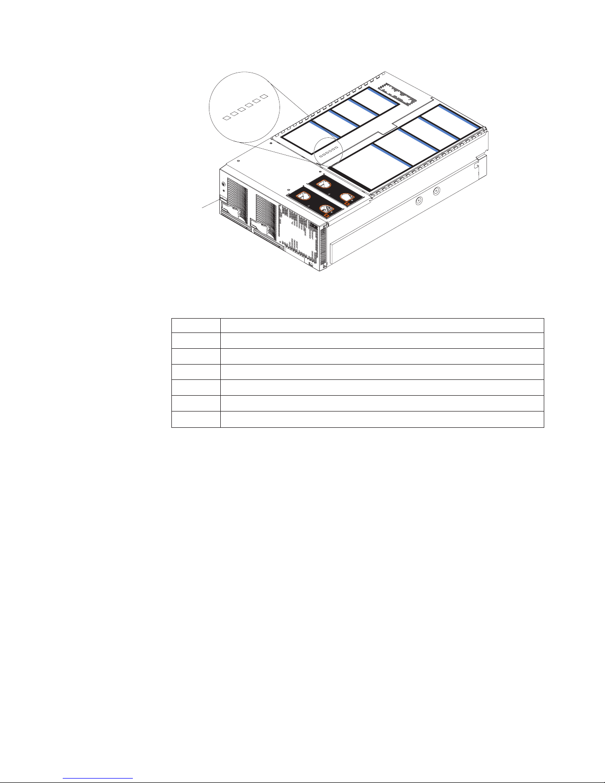
4
P
C
I
B
o
a
r
d
y
s
t
e
m
M
a
n
a
g
e
m
e
n
t
B
o
a
r
d
M
i
d
p
la
n
e
B
oa
r
L
ig
h
t-P
a
th
D
ia
IN
U
TES
d
g
n
o
s
t
ic
s
U
p
p
e
r
C
E
C
L
o
w
e
r C
E
C
3
1
2
ID label
1
2
4
3
5
6
C
o
m
N
O
T
E:
FO
R PR
O
PER
A
IR
FLO
W, R
F
R
O
NT O
F
BO
X
5
S
6
I
/O
Bo
a
r
d
m
o
n
F
R
U
N
u
m
b
e
rs
NOTE
:
F
OR
P
R
O
PE
R AIRF
LO
W, REP
LA
C
E F
A
FRON
N
W
ITH
T O
IN 2 M
F BO
X
E
PL
A
CE
F
ANW
ITH
IN
2
MINU
TES
Figure 28. Top cover LEDs
Table 4. Top cover LEDs
LED Fault
1 Upper SMP Expansion Module
2 Lower SMP Expansion Module
3 Center plane power
4 PCI-X power
5 Remote Supervisor Adapter
6 I/O board power
3. Once you know the general type of error and the general location of the
component involved, the next step is to check the system service label on the
outside top of the server.
This label gives an overview of internal components that correspond to each of
the six LEDs on the top of the server. This information, combined with the
information contained in the table “Light path LED errors” on page 190, can
often provide enough information to correct the indicated error.
4. If necessary, you can consult the illuminated LEDs on the indicated board. For
example, a microprocessor error will light the LED next to the failing
microprocessor on one of the SMP Expansion boards.
Chapter 3. Diagnostics 67
Page 78

Diagnostic programs and error messages
The server diagnostic programs are stored in upgradeable read-only memory
(ROM) on the I/O board. These programs are the primary method of testing the
major components of the server.
Diagnostic error messages indicate that a problem exists; they are not intended to
be used to identify a failing part. Troubleshooting and servicing of complex
problems that are indicated by error messages should be performed by trained
service personnel.
Sometimes the first error to occur causes additional errors. In this case, the server
displays more than one error message. Always follow the suggested action
instructions for the first error message that appears.
The following sections contain the error codes that might appear in the detailed test
log and summary log when running the diagnostic programs.
The error code format is as follows:
fff-ttt-iii-date-cc-text message
where:
fff is the three-digit function code that indicates the function being tested when
the error occurred. For example, function code 089 is for the
microprocessor.
ttt is the three-digit failure code that indicates the exact test failure that was
encountered.
iii is the three-digit device ID.
date is the date that the diagnostic test was run and the error recorded.
cc is the check value that is used to verify the validity of the information.
text message
is the diagnostic message that indicates the reason for the problem.
68 xSeries 445 Type 8870: Hardware Maintenance Manual and Troubleshooting Guide
Page 79

Text messages
The diagnostic text message format is as follows:
Function Name: Result (test specific string)
where:
Function Name
is the name of the function being tested when the error occurred. This
corresponds to the function code (fff) given in the previous list.
Result
can be one of the following:
Passed
This result occurs when the diagnostic test completes without any
errors.
Failed This result occurs when the diagnostic test discovers an error.
User Aborted
This result occurs when you stop the diagnostic test before it is
complete.
Not Applicable
This result occurs when you specify a diagnostic test for a device
that is not present.
Aborted
Warning
Specific String
Test
This is additional information that you can use to analyze the problem.
This result occurs when the test could not proceed because of the
system configuration.
This result occurs when a possible problem is reported during the
diagnostic test, such as when a device that is to be tested is not
installed.
Chapter 3. Diagnostics 69
Page 80

Starting the diagnostic programs
This section describes the general procedure to run the diagnostic programs on
either a standalone server or a 16-way configuration.
You can press F1 while running the diagnostic programs to obtain help information.
You also can press F1 from within a help screen to obtain online documentation
from which you can select different categories. To exit from help and return to
where you left off, press Esc.
Note: In a 16-way configuration, diagnostics are run on the server to which the
keyboard, mouse and video are attached. To run diagnostics on the second
server, the second server must be connected to a keyboard, video and
mouse or to a KVM switch.
Complete the following steps to start the diagnostic programs:
1. Turn on the server and watch the screen; then, continue with step 2 for 16-way
configuration, or with step 3 for all other models.
Note: For 16-way configuration, turn on both servers and watch the screen.
2. For 16-way configuration: When the message Searching for secondary
server, Press ESC to bypass partition merge and boot standalone appears,
press ESC; then continue with step 3.. The screen will display the message
Secondary server has been found.
3. When the message Press F1 for Configuration/Setup, Press F2 for
Diagnostics appears, press F2.
If a power-on password is set, the server prompts you for it. Type the power-on
password, and press Enter.
To run diagnostics on the secondary server in a a16-way configuration, perform
the previous steps for the primary server first, then for the secondary server.
Note: For 16-way configuration, the secondary server must be connected to a
KVM switch or to its own pointing device, keyboard, and monitor in order
to run diagnostic programs on that server. The procedure for starting
diagnostics is the same for both servers and the merge process can be
stopped from either the primary or secondary servers.
4. When the Diagnostic Programs screen appears, select either Extended or
Basic from the top of the screen.
5. Select the test you want to run from the list that appears; then, follow the
instructions on the screen.
Notes:
a. If the server stops during testing and you cannot continue, restart the server
and try running the diagnostic programs again. If the problem remains,
replace the component that was being tested when the server stopped.
b. The keyboard and mouse (pointing device) tests assume that a keyboard
and mouse are attached to the server.
c. If you run the diagnostic programs with no mouse attached to the server,
you will not be able to navigate between test categories using the Next Cat
and Prev Cat buttons. All other functions provided by mouse-selectable
buttons are also available using the function keys.
70 xSeries 445 Type 8870: Hardware Maintenance Manual and Troubleshooting Guide
Page 81

d. You can test the USB keyboard by using the regular keyboard test. The
e. You can view server configuration information (such as system configuration,
the diagnostic programs do not detect any hardware error but the problem
If
persists during normal server operations, a software error might be the cause. If
you suspect a software problem, see the information that comes with the software
package.
Diagnostic error codes are listed at “Diagnostic error codes” on page 211.
Viewing the test log
When the tests are completed, you can view the test log by selecting Utility from
the top of the screen and then selecting View Test Log.
Notes:
1. You can view the test log only while you are in the diagnostic programs. When
you exit the diagnostic programs, the test log is cleared (saved test logs are not
affected). To save the test log so that you can view it later, click Save Log on
the diagnostic programs screen and specify a location and name for the saved
log file.
2. To save the test log to a diskette, you must use a diskette that you have
formatted yourself; this function does not work with preformatted diskettes. If the
diskette has sufficient space for the test log, the diskette may contain other
data.
regular mouse test can test a USB mouse. Also, you can run the USB
interface test only if there are no USB devices attached.
memory contents, interrupt request (IRQ) use, direct memory access (DMA)
use, device drivers, and so on) by selecting Hardware Info from the top of
the screen.
Viewing the System Error log
You can also view the System Error log from the diagnostic programs. See the
instructions in “Error logs” on page 65.
Chapter 3. Diagnostics 71
Page 82

Verifying scalability and RXE cabling
This section describes the procedure to verify scalability and RXE cabling on a
16-way configuration. Begin the procedure by viewing the connections in each
8-way system:
From the diagnostic program main menu, select
1. Hardware Info
2. Summit Chips
A screen similar to the following is shown:
================================================================================
This_______ Connectd_to Ext Is Has Port Trans Recei Error
no Chip_._Port Chip_._Port Int Ready Cable Speed Error Error Count
-- ----------- ----------- --- ----- ----- ----- ----- ----- ----Scalability:
01 Scalab_1.P1 ........... Ext yes yes 1600 MHz no no 00
02 Scalab_1.P2 ........... Ext yes yes 1600 MHz no no 00
03 Scalab_1.P3 Scalab_2.P3 Ext yes yes 1600 MHz no no 00
04 Scalab_2.P1 ........... Ext yes yes 1600 MHz no no 00
05 Scalab_2.P2 ........... Ext yes yes 1600 MHz no no 00
06 Scalab_2.P3 Scalab_1.P3 Ext yes yes 1600 MHz no no 00
Memory:
07 Memory_1.P0 PCI-X__1.P0 Int yes yes 1000 MHz no no 00
08 Memory_1.P1 PCI-X__2.P0 Int yes yes 1000 MHz no no 00
09 Memory_2.P0 PCI-X__2.P1 Int yes yes 1000 MHz no no 00
10 Memory_2.PB ........... Ext yes no 250 MHz no no 00
PCI-X:
11 PCI-X__1.P0 Memory_1.P0 Int yes yes 1000 MHz no no 00
12 PCI-X__1.PA ........... Ext yes yes 250 MHz no no 00
13 PCI-X__2.P0 Memory_1.P1 Int yes yes 1000 MHz no no 00
14 PCI-X__2.P1 Memory_2.P0 Int yes yes 1000 MHz no no 00
===============================================================================
The information in the columns indicates:
1. The name of each port
2. The item the port is connected to
3. Whether the port is external or internal
4. Whether the port is it ready to operate
5. Whether the port has a cable attached to it
6. The port speed
7. Whether there are ″transmit errors″ posted by the chip
8. Whether there are ″receive errors″ posted by the chip
9. The number of ″receive errors″ (since the count was last cleared)
72 xSeries 445 Type 8870: Hardware Maintenance Manual and Troubleshooting Guide
Page 83

Scalability cabling
The verification checklist for the scalability ports is described in the following list.
Note: The “Connected to” information is not known for ports that had been
1. The “Connected to” column must be “unknown” for four ports, as shown.
2. The “Connected to” column must show that both “P3”s connect to each other.
3. The “Is Ready” just be “Yes” for all six ports.
4. The “Has Cable” must be “Yes” for all six ports.
5. The “Transmit” and “Receive” errors should both be “No” for all six ports.
After performing these checks for one server in the configuration, perform the
checks for the other server. The results must be identical.
RXE cabling
The cabling to an RXE100 Expansion Enclosure should be as follows:
Primary Port A to Secondary Port A
connected to the other server prior to booting as a standalone server for the
diagnostic programs.
Primary Port B to RXE100 Side A
Secondary Port B to RXE100 Side B
These connections can be verified with the following display (from the diagnostic
program main menu, select ″Hardware Info″ and ″Summit Chips″). The primary
display in the following example begins with ″Memory″:
=================================================================================
This_______ Connectd_to Ext Is Has Port Trans Recei Error
no Chip_._Port Chip_._Port Int Ready Cable Speed Error Error Count
-- ----------- ----------- --- ----- ----- ----- ----- ----- ----Memory:
07 Memory_1.P0 PCI-X__1.P0 Int yes yes 1000 MHz no no 00
08 Memory_1.P1 PCI-X__2.P0 Int yes yes 500 MHz no no 00
09 Memory_2.P0 PCI-X__2.P1 Int yes yes 500 MHz no no 00
10 Memory_2.PB RXE100_A.PA Ext yes yes 500 MHz no no 00
PCI-X:
11 PCI-X__1.P0 Memory_1.P0 Int yes yes 1000 MHz no no 00
12 PCI-X__1.PA ........... Ext yes yes 250 MHz no no 00
13 PCI-X__2.P0 Memory_1.P1 Int yes yes 500 MHz no no 00
14 PCI-X__2.P1 Memory_2.P0 Int yes yes 500 MHz no no 00
RXE100:
15 RXE100_A.PA Memory_2.PB Ext yes yes 500 MHz no no 00
16 RXE100_A.P1 ........... Int yes yes 250 MHz no no 00
================================================================================
In line number 12, Port A is shown as ″Ready″, but the ″Connected_to″ is unknown.
In line number 10, Port B is shown as ″Connected_to″ RXE100 Side A, Port A.
In line number 16, Port 1 is the internal port connecting to Side B, and it is
″Ready″.
Chapter 3. Diagnostics 73
Page 84

The secondary display in the following example begins with ″Memory″:
=================================================================================
This_______ Connectd_to Ext Is Has Port Trans Recei Error
no Chip_._Port Chip_._Port Int Ready Cable Speed Error Error Count
-- ----------- ----------- --- ----- ----- ----- ----- ----- ----Memory:
07 Memory_1.P0 PCI-X__1.P0 Int yes yes 1000 MHz no no 00
08 Memory_1.P1 PCI-X__2.P0 Int yes yes 500 MHz no no 00
09 Memory_2.P0 PCI-X__2.P1 Int yes yes 500 MHz no no 00
10 Memory_2.PB RXE100_B.PB Ext yes yes 500 MHz no no 00
PCI-X:
11 PCI-X__1.P0 Memory_1.P0 Int yes yes 1000 MHz no no 00
12 PCI-X__1.PA ........... Ext yes yes 250 MHz no no 00
13 PCI-X__2.P0 Memory_1.P1 Int yes yes 500 MHz no no 00
14 PCI-X__2.P1 Memory_2.P0 Int yes yes 500 MHz no no 00
RXE100:
15 RXE100_B.P1 ........... Int yes yes 250 MHz no no 00
16 RXE100_B.PB Memory_2.PB Ext yes yes 500 MHz no no 00
================================================================================
In line number 12, Port A is shown as ″Ready″, but the ″Connected_to″ is unknown.
In line number 10, Port B is shown as ″Connected_to″ RXE100 Side B, Port B.
In line number 15, Port 1 is the internal port connecting to Side A, and it is ″Ready″.
Testing the scalability and RXE cabling
There are 12 ports on each xSeries 445 chassis that can be tested:
1. The six scalability ports
2. The two RIOG ports (Port A and Port B)
3. The four ports on the Remote Expansion Enclosure:
a. The two internal ports (Port A and Port B)
b. The two internal ports (between Side A and Side B)
Depending on the BIOS determination of what is present on the system, some of
the ports will not be selectable (greyed out), shown with a ″.........″:
Note: When starting the diagnostic programs, make sure that Esc is pressed on
the primary server first (see step 2 on page 70 of “Starting the diagnostic
programs” on page 70). The merge must be bypassed on the primary server
first. If Esc is pressed on the secondary server first, some ports will be
disabled, greying out the test for those ports.
v If SMP2 is not present, all 4 entries under SMP2 will be greyed out.
v If RXE100 is not present, all 4 RXE100 entries will be greyed out; or, if either
side is not present, that side will be greyed out. (The SideB shown below is not
present.)
v If the port being tested blocks access to the chip controlling that port, that entry
will be greyed out. An example is shown below, ″RXE100, SideA Port″. Testing
that port will drive traffic on the cable between SideA and the xSeries 445 so that
the Summit chip on the RXE100 cannot be accessed to stop the test.
74 xSeries 445 Type 8870: Hardware Maintenance Manual and Troubleshooting Guide
Page 85

======================================================================
SMP1: Scalability Port1 __________
======================================================================
Scalability Port2 __________
Scalability Port3 __________
RXE Expansion Port A __________
SMP2: Scalability Port1 __________
Scalability Port2 __________
Scalability Port3 __________
RXE Expansion Port B __________
RXE100, SideA Port ..........
RXE100, from SideA to SideB __________
RXE100, from SideB to SideA ..........
RXE100, SideB Port ..........
Use the following procedure to test any of these 12 ports:
1. Turn on pinging for two seconds.
2. Count the pings issued, the pings received, and the errors received.
A port passes this test if both:
1. The port error status indicates:
a. no transmit errors
b. no receive errors
The percentage-good determined by (pings received) divided by (pings issued)
2.
is greater than 98%.
However, a test can fail for many reasons. These checks are made just before the
pinging is set to start:
1. The port is not initialized.
2. The port has no cable.
3. The cabling detected by BIOS during POST is invalid.
Each failure shows a display of what the error is (for approximately three seconds).
Recovering BIOS code
If the BIOS code has become damaged, such as from a power failure during a flash
update, the server might not restart correctly or might not display video (no video).
You can recover the BIOS code using the BIOS code page jumper and a BIOS
flash diskette.
Note: Yo u can download a BIOS flash diskette from the World Wide Web.
v Use the ServerGuide program to make a BIOS flash diskette. Go to
recover the BIOS code:
To
1. Turn off the server and peripheral devices and disconnect all external cables
and power cords; then, remove the cover (see “Opening the cover” on page
82).
2. Remove fans 3 and 4 (see “Replacing fans 3 and 4” on page 123).
3. Locate the boot recovery (BIOS) jumper (J28) on the I/O board.
http://www.ibm.com/pc/support/, click IBM Server Support, and make the
selections for the server.
Chapter 3. Diagnostics 75
Page 86

3
12
Jumper (J28)
4. Move the jumper from pins 1 and 2 to pins 2 and 3 to enable the BIOS back
page.
5. Reconnect all external cables and power cords and turn on the peripheral
devices.
6. Insert the BIOS flash diskette into the diskette drive.
7. Restart the server. The system begins the power-on self-test (POST) and
BIOS flash.
8. Select 1 - Update POST/BIOS from the menu that contains various flash
(update) options.
9. When prompted as to whether you want to save the current code to a diskette,
press N.
10. When prompted to choose a language, select a language (from 0 to 7) and
press Enter to accept your choice.
11. Do not restart the system at this time.
12. Remove the BIOS flash diskette from the diskette drive.
13. Turn off the server.
14. Move the jumper on J28 to pins 1 and 2 to return to normal startup mode.
15. Replace fans 3 and 4 (see “Replacing fans 3 and 4” on page 123).
16. Restart the server.
17. Replace the cover (see “Closing the cover” on page 125).
Ethernet controller troubleshooting
The method of testing the Ethernet controller depends on which operating system is
being used (see the Ethernet controller device driver README file).
You can use the Ethernet wrap test to determine if a hardware problem is causing
the Ethernet connection to fail. To perform the Ethernet wrap test, use the wrap
plug (FRU 48P9494) with the diagnostic tests.
Note: The wrap plug connects to the Ethernet port. Do not connect the wrap plug
to the serial port of the Remote Supervisor Adapter.
76 xSeries 445 Type 8870: Hardware Maintenance Manual and Troubleshooting Guide
Page 87

If the problem still exists after checking the operating system documentation, try the
following:
v Make sure that the cable is installed correctly.
The network cable must be securely attached at all connections. If the cable is
attached but the problem remains, try a different cable.
If you set the Ethernet controller to operate at 100 Mbps, you must use Category
5 cabling.
If you directly connect two workstations (without a hub), or if you are not using a
hub with X ports, use a crossover cable.
Note: To determine whether a hub has an X port, check the port label. If the
label contains an X, the hub has an X port.
v Determine if the hub supports auto-negotiation. If not, try configuring the
integrated Ethernet controller manually to match the speed and duplex mode of
the hub.
v Check the Ethernet controller lights on the server rear panel.
These lights indicate whether a problem exists with the connector, cable, or hub.
– The Ethernet Link Status light illuminates when the Ethernet controller
receives a LINK pulse from the hub. If the light is off, there might be a
defective connector or cable, or a problem with the hub.
– The Ethernet Transmit/Receive Activity light illuminates when the Ethernet
controller sends or receives data over the Ethernet Network. If the Ethernet
Transmit/Receive Activity light is off, make sure that the hub and network are
operating and that the correct device drivers are loaded.
Check the LAN activity light (if available) on the rear of the server. The LAN
v
activity light is illuminated when data is active on the Ethernet network. If the
LAN activity light is off, make sure that the hub and network are operating and
that the correct device drivers are loaded.
v Make sure that you are using the correct device drivers, which are supplied with
the server.
v Check for operating-system-specific causes for the problem.
v Make sure that the device drivers on the client and server are using the same
protocol.
the Ethernet controller still cannot connect to the network, inform the network
If
administrator.
Chapter 3. Diagnostics 77
Page 88

78 xSeries 445 Type 8870: Hardware Maintenance Manual and Troubleshooting Guide
Page 89

Chapter 4. Installing options
This chapter provides instructions to help you install options in the server. Some
option-removal instructions are provided in case you need to remove one option to
install another. For a list of supported options for the server, see the ServerProven
list at http://www.ibm.com/pc/compat/.
Installation guidelines
Before you begin to install options in the server, read the following information:
v Become familiar with the information provided in “Handling static-sensitive
devices” on page 80, and “Safety information” on page 257. These guidelines will
help you work safely with the server and options.
v Make sure that you have an adequate number of properly grounded electrical
outlets for the server, monitor, and other devices that you will connect to the
server.
v Back up all important data before you make changes to disk drives.
v Have a small flat-blade screwdriver available.
v You do not need to turn off the server to install or replace hot-swap power
supplies, hot-swap fans, or hot-plug Universal Serial Bus (USB) devices.
v Blue on a component indicates touch points, where a you can grip t he
component to remove it from or install it in the server, open or close a latch, and
so on.
v Orange on a component or an orange label on or near a component indicates
that the component can be hot-swapped, which means that if the server and
operating system support hot-swap capability, you can remove or install the
component while the server is running. (Orange can also indicate touch points on
hot-swap components.) See the instructions for removing or installing a specific
hot-swap component for any additional procedures that you might have to
perform before you remove or install the component.
v For a list of supported options for the server, go to
http://www.ibm.com/pc/compat/.
®
Working inside the server with power on
The server supports hot-swap devices and is designed to operate safely while
turned on with the cover removed. Follow these guidelines when you work inside a
server that is turned on:
v Avoid loose-fitting clothing on your forearms. Button long-sleeved shirts before
working inside the server; do not wear cuff links while you are working inside the
server.
v Do not allow your necktie or scarf to hang inside the server.
v Remove jewelry, such as bracelets, rings, necklaces, and loose-fitting wrist
watches.
v Remove items from your shirt pocket, such as pens or pencils, that could fall into
the server as you lean over it.
v Avoid dropping any metallic objects, such as paper clips, hairpins, and screws,
into the server.
© Copyright IBM Corp. 2003 79
Page 90

Handling static-sensitive devices
Attention: Static electricity can damage electronic devices and the server. To
avoid damage, keep static-sensitive devices in their static-protective packages until
you are ready to install them.
To reduce the possibility of damage from electrostatic discharge, observe the
following precautions:
v Limit your movement. Movement can cause static electricity to build up around
you.
v Handle the device carefully, holding it by its edges or its frame.
v Do not touch solder joints, pins, or exposed printed circuitry.
v Do not leave the device where others can handle and damage it.
v While the device is still in its static-protective package, touch it to an unpainted
metal part of the server for at least 2 seconds. This drains static electricity from
the package and from your body.
v Remove the device from its package and install it directly into the server without
setting it down. If it is necessary to set down the device, put it back into its
static-protective package. Do not place the device on the server cover or on a
metal surface.
v Take additional care when handling devices during cold weather. Heating reduces
indoor humidity and increases static electricity.
System reliability considerations
To help ensure proper cooling and system reliability, make sure that:
v Each of the drive bays has a drive or a filler panel and electromagnetic
compatibility (EMC) shield installed in it.
v If the server has only one symmetrical multiprocessing (SMP) Expansion Module
installed ensure that the SMP baffle is installed during normal operation.
v There is adequate space around the server to allow the server cooling system to
work properly. Leave approximately 50 mm (2.0 in.) of open space around the
front and rear of the server. Do not place objects in front of the fans.
v Do not leave open spaces above or below an installed server in a rack cabinet.
To prevent damage to server components, always install a blank filler panel to
cover the open space and to ensure proper air circulation.
v You have followed the cabling instructions that come with optional adapters.
v You have replaced a failed fan within 48 hours.
v You have replaced a hot-swap drive within 2 minutes of removal.
v Microprocessor socket 4 always contains either a microprocessor baffle or a
microprocessor and heat sink.
80 xSeries 445 Type 8870: Hardware Maintenance Manual and Troubleshooting Guide
Page 91

Major components of the xSeries 445
The following illustration shows the locations of major components in the server.
Note: The illustrations in this document might differ slightly from your hardware.
Retention bracket
Fan 1
NOTE
:
FO
R
P
R
OP
E
FRO
N
T O
F B
O
Fan 3
Fan 2
N
O
TE
:
F
O
R PR
F
RON
T O
R A
IRFL
O
W, R
EP
LA
CE
F
ANW
IT
X
Fan 4
O
PE
R
AIR
F
LO
W, RE
F
BO
X
H
IN 2 M
IN
U
TES
PL
A
C
E F
A
N
W
ITH
IN 2 M
IN
UTE
S
SMP baffle
Heat-sink
Microprocessor
Center
plane
DIMM
DIMM
access
doors
SMP
Cover
Expansion
Module
VRM
EMC shield
(for single SMP
Expansion Module)
Thumbscrews
Figure 29. Major components of the xSeries 445
Hot-swap
power supply
Hard disk
drive
Shipping thumbscrews
Bezel
DVD-ROM
drive
Chapter 4. Installing options 81
Page 92

Opening the cover
Complete the following steps to open the server cover:
1. Review the information in Working inside the server with power on, “Safety
2. Pull out on the quick release latches on each side of the server; then, pull the
Latch
information” on page 257, and “Installation guidelines” on page 79.
server out of its rack enclosure until it stops.
N
O
T
E
:
F
O
R
P
R
O
P
E
R
A
IR
F
L
O
W, R
E
P
N
O
T
L
A
C
E
:
F
O
R
F
R
O
NT
E
F
A
F
N
R
W
O
P
R
O
PE
O
F
B
O
X
IT
N
T
H
O
IN
F
2
B
R
A
IR
F
LO
M
O
IN
X
U
T
E
W, R
E
P
S
L
A
C
E
F
A
N
W
IT
H
IN
2 M
IN
U
T
E
S
Figure 30. Opening the cover
3. Pull the release latch on the left half of the top cover to the right.
4. Using the finger hole in the release latch, open the left half of the cover; then,
open the right half of the cover.
Attention: For proper cooling and airflow, close the cover before turning on
the server. Operating the server for extended periods of time (more than 30
minutes) with the cover open might damage server components.
82 xSeries 445 Type 8870: Hardware Maintenance Manual and Troubleshooting Guide
Page 93
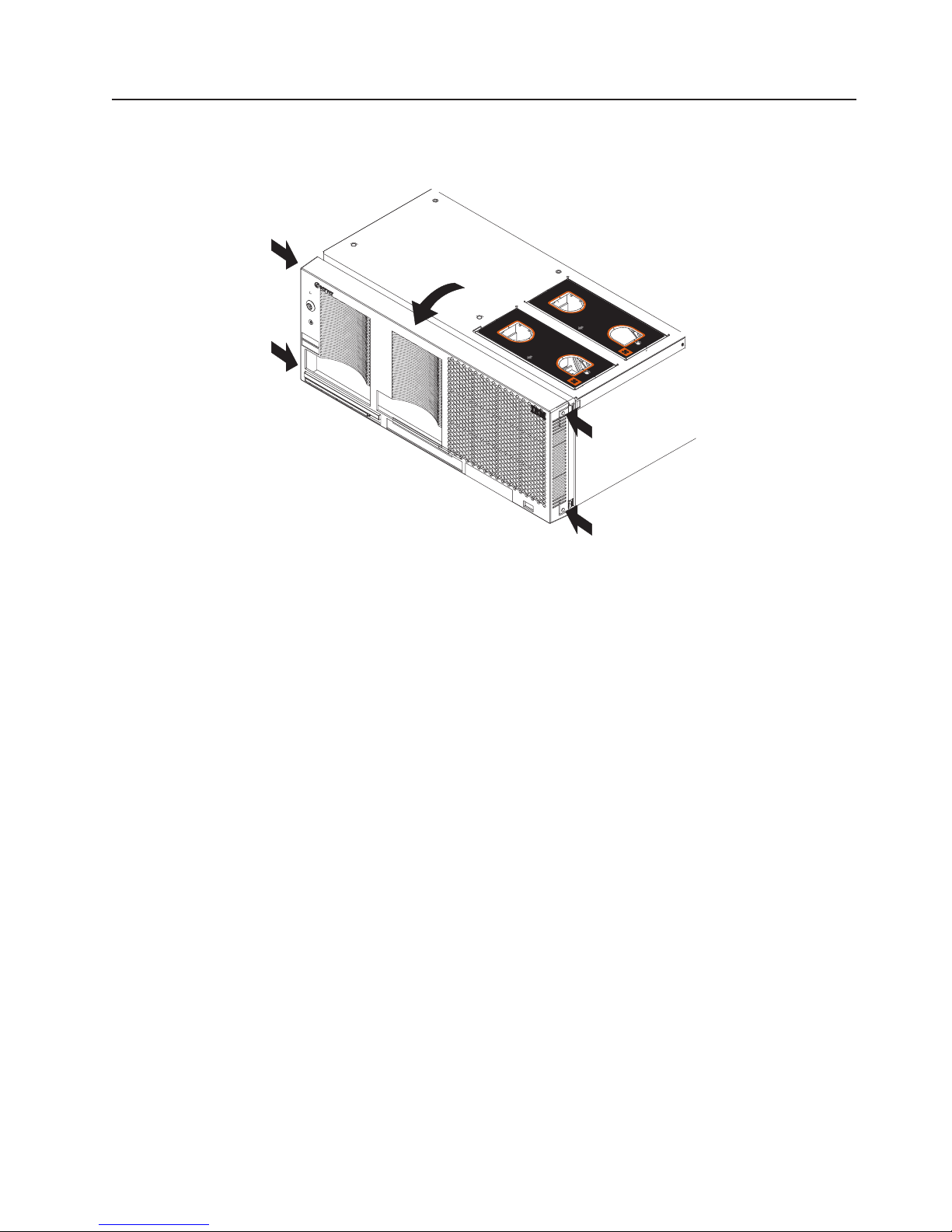
Removing and replacing the bezel
Complete the following steps to remove and replace the server bezel:
N
O
T
E
:
F
O
R
P
R
O
P
E
R
A
IR
F
L
O
W, R
E
P
N
O
T
E
:
F
O
R
P
R
O
P
E
R
A
IR
F
L
O
W, R
E
P
L
A
C
F
R
O
N
T
O
F
B
O
X
L
A
C
E
F
F
R
O
E
F
A
N
A
N
W
N
T
O
W
IT
H
IT
H
F
B
IN
2
IN
2
O
X
M
I
N
M
IN
U
T
E
S
U
T
E
S
Figure 31. Removing the bezel
1. Remove the bezel.
a. Press on the two tabs at the top edge of the bezel, and pull the top of the
bezel slightly away from the server.
b. Press on the two tabs at the bottom edge of the bezel, and pull the bezel off
the server. Store the bezel in a safe place.
Replace the bezel.
2.
a. Align the four tabs with the slots in the server chassis.
b. Press firmly against the front of the bezel until it snaps into place.
Chapter 4. Installing options 83
Page 94

Removing and replacing a hot-swap power supply
The two hot-swap power supplies in the server can be removed and replaced
without turning off the server. This section provides instructions for removing and
installing the hot-swap power supplies.The following notes and safety information
contains information you must consider when removing or installing a hot-swap
power supply:
v During normal operation, both power supplies must be installed for proper
operation and cooling.
v The xSeries 445 server requires a 220 V power connection for full power-supply
redundancy. Whenever possible, use a 220 V connection for all configurations.
However, you can use a 110 V connection, but without power-supply redundancy.
v If the server power supplies are not running redundantly, a power supply LED will
be lit on the Light Path panel (see “Light path LED errors” on page 190).
Statement 8
CAUTION:
Never remove the cover on a power supply or any part that has the following label
attached.
Hazardous voltage, current, and energy levels are present inside any component that
has this label attached. There are no serviceable parts inside these components. If
you suspect a problem with one of these parts, contact a service technician.
Power light Power supply 1
Power supply 2
Power-on light
Power button
Reset button
Power supply
latch
Handle
Figure 32. Hot-swap power supply
Complete the following steps to remove and replace a power supply:
1. Review the information in “Installation guidelines” on page 79 and “Safety
information” on page 257.
84 xSeries 445 Type 8870: Hardware Maintenance Manual and Troubleshooting Guide
Page 95

2. Remove the front bezel (see “Removing and replacing the bezel” on page 83 for
instructions on removing the front bezel).
Hot-swap
power supply
Release latch
AC LED
DC LED
Power supply handle
(in open position)
Figure 33. Removing a power supply
3. Press the release latch; then, lift the handle on the power supply to the open
position and remove the power supply.
Hot-swap
power supply
Release latch
AC LED
DC LED
Power supply handle
(in open position)
Figure 34. Installing a power supply
4. Install the new power supply:
a. Place the handle on the power supply in the open position.
b. Slide the power supply into the chassis and press the handle to the closed
position.
Chapter 4. Installing options 85
Page 96

5. Verify that the dc power LED and the ac power LED on the power supply are lit,
indicating that the power supply is operating properly.
6. Replace the front bezel on the server (see “Removing and replacing the bezel”
on page 83 for instructions).
PCI and PCI-X adapters
The following notes describe the types of adapters that the server supports and
other information that you must consider when installing an adapter:
Note: The illustrations in this document might differ slightly from your hardware.
PCI-X slot 5
(133 )MHz
PCI-X slot 6
(133 MHz)
PCI-X slot 4
(100 )MHz
PCI-X slot 3
(100 )MHz
PCI-X slot 2
(66 )MHz
Attention LED
Power LED
PCI-X slot 1
(66 )MHz
Figure 35. PCI-X slots
PCI and PCI-X adapter considerations
Before you install adapters, review the following:
v Locate the documentation that comes with the adapter and follow those
instructions in addition to the instructions in this chapter.
v If you need to change the switch settings or jumper settings on your adapter,
follow the instructions that come with the adapter.
v Video adapters are not supported.
v Some long adapters have extension handles or brackets installed. Before
installing the adapter, you must remove the extension handle or bracket.
v The server uses a rotational interrupt technique to configure PCI-X adapters. Yo u
can use this technique to install PCI-X adapters that currently do not support
sharing of PCI-X interrupts.
86 xSeries 445 Type 8870: Hardware Maintenance Manual and Troubleshooting Guide
Page 97

v The server scans devices and PCI-X slots to assign system resources in the
following order: DVD-ROM drive; disk drives; integrated SCSI devices; PCI-X
slots 1, 2, 3, 4, 5, 6; and the integrated Ethernet controller. If an RXE-100
enclosure is attached to the server, the scan continues in sequence with PCI
slots 7, 8, 9, 10, 11, 12, 13, 14, 15, 16, 17, and 18.
Note: The POST/BIOS settings control the scanning order of the adapters in the
PCI-X slots. However, if multiple (like) adapters from a single vendor are
installed, the first installed adapter will control the ROM space for all
additional like adapters that may be added at a later time. This action
overrides the scan sequence set in the POST/BIOS. Some ServeRAID
adapters have this impact on the scan sequence.
v You can use the Configuration/Setup Utility program to change the sequence and
have the server scan one of the first six PCI slots before it scans the integrated
devices. You cannot change the scan sequence of the PCI slots in an RXE-100
enclosure.
v You can install both PCI and PCI-X adapters in the same bus. However, if you
install a PCI adapter and a PCI-X adapter in the same bus, the PCI-X features of
the PCI-X adapter will be disabled and the adapter will function as a PCI adapter.
v You can install PCI or PCI-X adapters of speeds faster than what is labeled for a
particular PCI-X bus. For example, if you install two 133 MHz adapters into slots
that are labeled as 100 MHz slots, the adapters will operate at 100 MHz.
v If you install a 33 MHz and a 66 MHz adapter in the same bus, the bus speed
will match that of the slowest adapter.
v If a single 133 MHz adapter is installed in PCI-X Bus B (slot 3 and 4), and the
other slot in PCI-X Bus B is empty, the adapter will operate at 133 MHz.
v The server supports six hot-plug 64-bit adapters in the expansion slots located
on the PCI-X board.
Note: Yo u can add up to 12 PCI-X slots to the server by connecting the server
to a remote I/O expansion enclosure. For more information about the
expansion enclosure and how to connect the server to it, see the
documentation that comes with your expansion enclosure.
Bus Slot Supported adapter speed (MHz)
A 1 66
A 2 66
B 3 100 (133 if slot 4 is empty)
B 4 100 (133 if slot 3 is empty)
C 5 133
D 6 133
v The server supports 3.3 V adapters; it does not support 5.0 V adapters.
v Do not install a PCI-X adapter in PCI-X slot 1 if you are going to install the serial
port that comes with the server. See “Installing the serial port” on page 91 for
instruction for installing the serial port.
Chapter 4. Installing options 87
Page 98

Complete the following steps to install an adapter:
1. Review the information in “Safety information” on page 257, Working inside the
server with power on, and “Handling static-sensitive devices” on page 80.
2. Use the operating system to disable the Active PCI-X slot; then, insert or
remove a hot-plug PCI or PCI-X adapter. Some operating systems do not
support the enabling and disabling of a PCI-X slot. If your operating system
does not support this function, then turn off the server, and disconnect all
external cables and power cords before proceeding.
3. Pull out on the quick release latches on each side of the server; then, pull the
server out of its rack enclosure until it stops.
4. Open the top cover.
Note: Inside the server there are six PCI-X slots: two 66 MHz, two 100 MHz,
and two 133 MHz. Before attempting to install a new adapter, be sure
there is an available slot for it. If you need additional PCI-X slots, you
can purchase a Remote Expansion Enclosure either from your IBM
marketing representative or authorized reseller.
Adapter guide
Ta b
PCI-X
divider
Adapter
retention
latch
Attention
LED
Power
LED
NOTE:FOR PROPER AIRFLOW, REPLACE FANWITHIN 2 MINUTES
NOTE:FOR PROPER AIRFLOW, REPLACE FANWITHIN 2 MINUTES
FRONT OF BOX
FRONT OF BOX
Figure 36. PCI-X slot components
5. See the documentation that comes with your adapter for any cabling
instructions; then, set any jumpers or switches as described by the adapter
manufacturer.
Note: Route adapter cables before you install the adapter.
88 xSeries 445 Type 8870: Hardware Maintenance Manual and Troubleshooting Guide
Page 99

6. Install the adapter:
a. Open the blue adapter guide by lifting the front edge, as shown in the
illustration.
b. Push the orange adapter retention latch toward the rear of the server and
open the tab.
c. Remove the expansion-slot cover. If you are hot-swapping a PCI or PCI-X
adapter do not remove the PCI-X divider.
d. Carefully grasp the adapter by its top edge or upper corners and align it
with the connector on the I/O board.
e. If necessary remove the extension handles or bracket before installing a
long adapter.
Attention: When you install an I/O adapter, be sure the adapter is
correctly seated in the connector slot. Improperly seated adapters might
cause damage to the board, the riser card, or the adapter.
f. Press the adapter firmly into the adapter connector.
g. If they were removed, reinstall the PCI-X dividers between the Active PCI-X
adapter slots.
h. Push down on the blue adapter guide to keep the adapter steady.
i. Close the tab; then, push down on the orange adapter retention latch until it
clicks into place, securing the adapter.
7. Connect the internal cables to the adapter. If you are installing a ServeRAID
adapter, see “Cabling a ServeRAID adapter” for instructions.
8. If you have other options to install or remove, do so now.
9. Close the cover on the server; then, reinstall the server in the rack and
connect all external cables.
10. Enable the slot or turn on the server, depending on your operating system.
Cabling a ServeRAID adapter
Some xSeries 445 models come with an optional IBM ServeRAID adapter installed
to control the internal hot-swap hard disk drives and external hard disk drives. If the
server did not come with an optional IBM ServeRAID adapter installed; then, see
your ServeRAID adapter option documentation for complete instructions on
installing a ServeRAID adapter in the server and for additional information on
ServeRAID adapters.
Servers without an optional IBM ServeRAID adapter installed come with two SCSI
cables:
v One end of the first SCSI cable is attached to the connector on the SCSI
backplane, and the other end is attached to the connector for the integrated
SCSI controller behind fans 3 and 4.
v The second SCSI cable is preinstalled along the inside of the server chassis and
both ends are loose inside the server. When you install a ServeRAID adapter,
you will connect this cable to the adapter and the SCSI backplane on the I/O
board.
Chapter 4. Installing options 89
Page 100
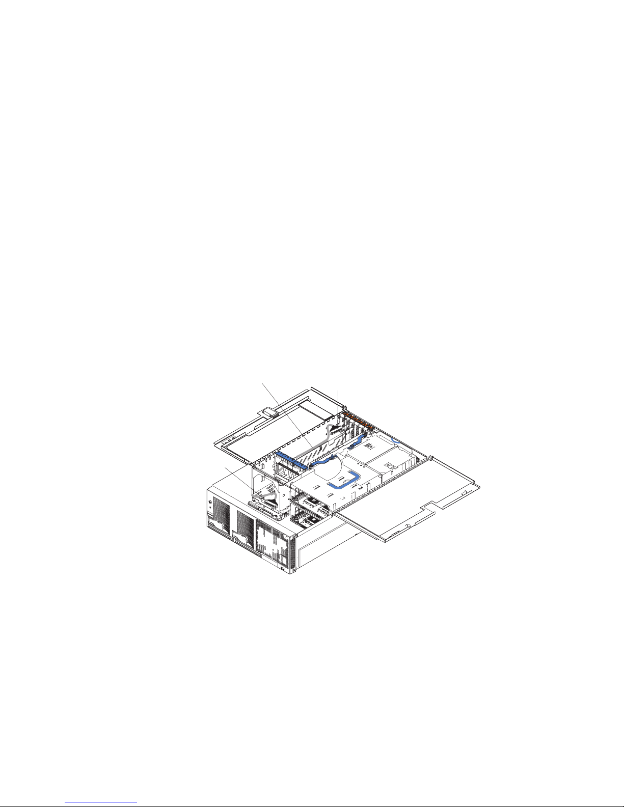
The following procedure describes the internal cabling needed to install a
ServeRAID adapter.
Important: When installing multiple ServeRAID adapters in a server that has the
PCI-X slot enabled for high scan (boot) priority, ensure that the ServeRAID adapter
controlling the startup (boot) drive is installed in a PCI slot that is scanned before
the PCI slots that contain the other ServeRAID adapters. See “PCI and PCI-X
adapters” on page 86.
Complete the following steps to cable the ServeRAID adapter.
1. Review the information in “Safety information” on page 257 and “Installation
guidelines” on page 79.
2. Turn off the server and disconnect all power cords and external cables; then,
open the server cover (see “Opening the cover” on page 82).
3. Remove fans 3 and 4, which are located just behind the PCI-X slots.
4. Disconnect the short SCSI cable from the SCSI backplane and the integrated
SCSI controller on the I/O board; then, store this short cable in a safe place for
future use.
5. Install the ServeRAID adapter in a PCI-X slot (see “PCI and PCI-X adapters”
on page 86).
6. Locate one end of the preinstalled SCSI cable and connect it to the
ServeRAID adapter.
Preinstalled
SCSI cable
Connect to
ServeRAID adapter
Connect to
SCSI backplane
Figure 37. Location of preinstalled SCSI cable
7. Locate the other end of the preinstalled SCSI cable and connect it to the SCSI
backplane on the I/O board.
90 xSeries 445 Type 8870: Hardware Maintenance Manual and Troubleshooting Guide
 Loading...