

Page 1

®
xSeries 380
User’s Reference
Page 2

Page 3

IBM
xSeries 380
User’s Reference
SC06-P464-70
Page 4

Note: Before using this information and the product it supports, be sure to read the general information in Appendix A,
“Product warranties and notices,” on page 79.
First Edition (July 200 1)
© Copyright International Business Machines Corporation 2001. All rights reserved.
US Government Users Restricted Rights – Use, duplication or disclosure restricted by GSA ADP Schedule Contract with
IBM Corp.
Page 5
© Copyright IBM Corp. 2001 iii
Safety
Before installing this product, read the Safety Information.
Antes de instalar este produto, leia as Informações de Segurança.
Læs sikkerhedsforskrifterne, før du installe rer dette produk t.
Lees voordat u dit product installeert eerst de veiligheidsvoorschriften.
Ennen kuin asennat tämän tuotteen, lue turvaohjeet kohdasta Safety Information.
Avant d'installer ce produit, lisez les consignes de sécurité.
Vor der Installation dieses Produkts die Sicherheitshinweise lesen.
Prima di installare questo prodotto, leggere le Informazioni sulla Sicurezza
Les sikkerhetsinformas jo nen (S afety Information) før du installerer dette produktet.
Antes de instalar este produto, leia as Informações sobre Segurança.
Pred instalací tohoto produktu si prectete prírucku bezpecnostních instrukcí.
Page 6
iv xSeries 380: User’s Reference
Antes de instalar este producto lea la información de seguridad.
Läs säkerhetsinformationen innan du installerar den här produkten.
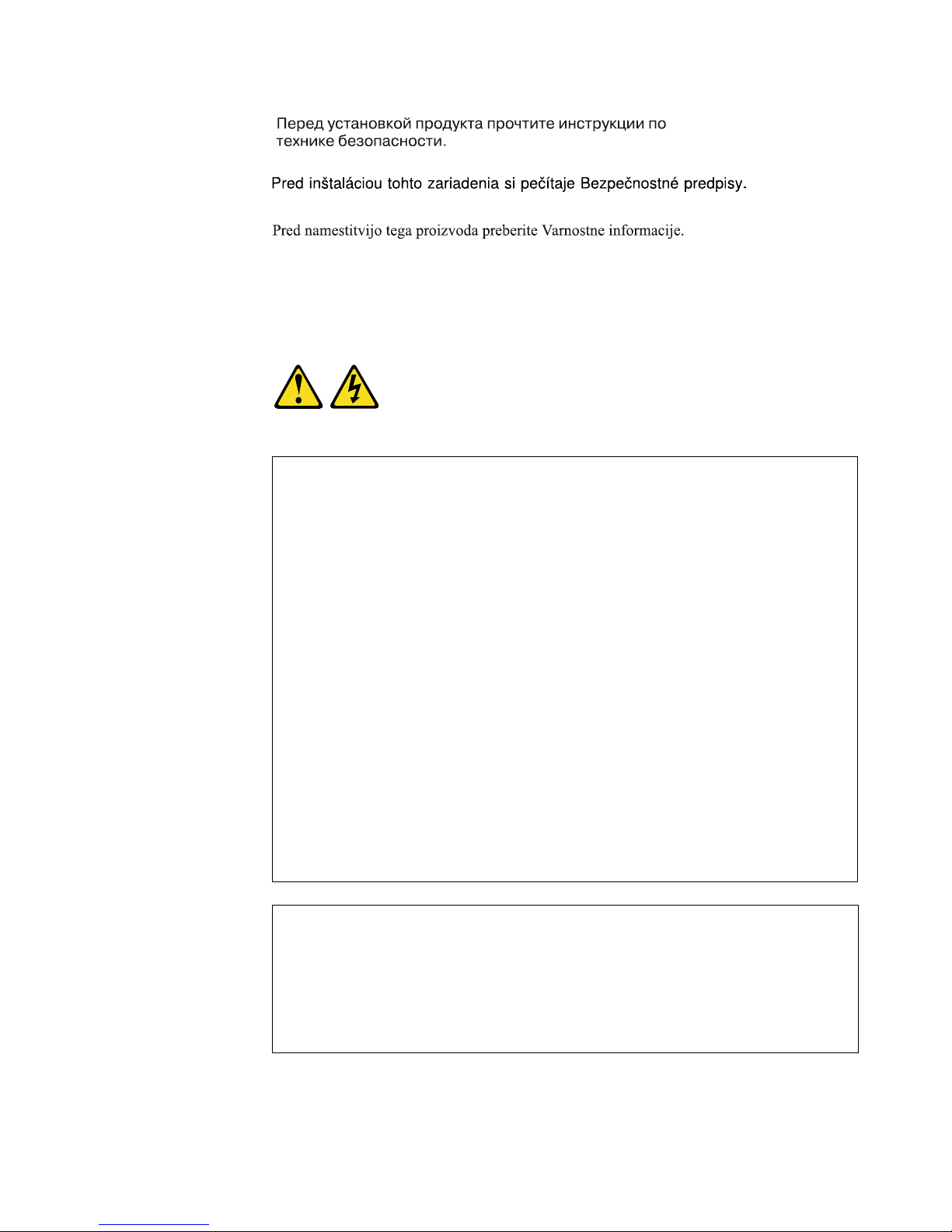
Statement 1
DANGER
To Connect: To Disconnect:
1. Turn everything OFF.
2. First, attach all cables to devices.
3. Attach signal cables to connectors.
4. Attach power cords to outlet.
5. Turn device ON.
1. Turn everything OFF.
2. First, remove power cords from outlet.
3. Remove signal cables from connectors.
4. Remove all cables from devices.
Electrical current from power, telephone, and communication cables is
hazardous.
To avoid a shock hazard:
• Do not connect or disconnect any cables or perform installation,
maintenance, or reconfiguration of this product during an electrical
storm.
• Connect all power cords to a properly wired and grounded electrical
outlet.
• Connect to properly wired outlets any equipment that will be attached
to this product.
• When possible, use one hand only to connect or disconnect signal
cables.
• Never turn on any equipment when there is evidence of fire, water, or
structural damage.
• Disconnect the attached power cords, telecommunications systems,
networks, and modems before you open the device covers, unless
instructed otherwise in the installation and configuration procedures.
• Connect and disconnect cables as described in the following table
when installing, moving, or opening covers on this product or
attached devices.
Page 7
v
Statement 3
CAUTION:
When laser products (such as CD-ROMs, DVD drives, fiber optic devices, or
transmitters) are installed, note the following:
• Do not remove the covers. Removing the covers of the laser product could
result in exposure to hazardous laser radiation. There are no serviceable
parts inside the device.
• Use of controls or adjustments or performance of procedures other than
those specified herein might result in hazardous radiation exposure.
DANGER
Some laser products contain an embedded Class 3A or Class 3B laser
diode. Note the following.
Laser radiation when open. Do not stare into the beam, do not view
directly with optical instruments, and avoid direct exposure to the beam.
Class 1 Laser Product
Laser Klasse 1
Laser Klass 1
Luokan 1 Laserlaite
Appareil A Laser de Classe
1
`
Page 8
vi xSeries 380: User’s Reference
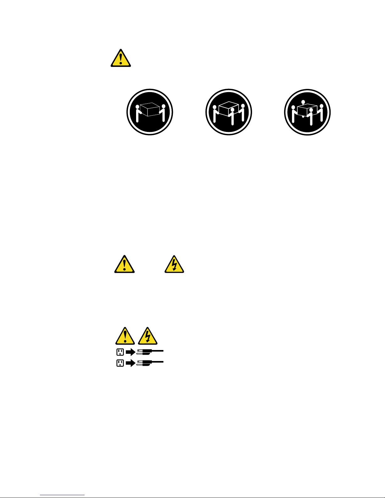
Statement 4
CAUTION:
Use safe practices when lifting.
Statement 5
CAUTION:
The power control button on the device and the power switch on the power
supply do not turn off the electrical current supplied to the device. The device
also might have more than one power cord. T o remove all electrical current fro m
the device, ensure that all power cords are disconnected from the power
source.
≥18 kg (37 lbs)
≥32 kg (70.5 l bs)
≥55 kg (121.2 lbs)
1
2
Page 9
vii
Statement 8
CAUTION:
Never remove the cover on a power supply or any part that has the following
label attached.
Hazardous voltage, current, and energy levels are present inside any
component that has this label attached. There are no serviceable parts inside
these components. If you suspect a problem with one of these parts, contact a
service technician.
Statement 10
CAUTION:
Do not place any object weighing more than 82 kg (180 lbs.) on top of rackmounted devices.
Statement 13
CAUTION:
Overloading a branch circuit is potentially a fire hazard and a shock hazard
under certain conditions. To avoid these hazards, ensure that your system
electrical requirements do not exceed branch circuit protection requirements.
Refer to the information that is provided with your IBM device for electrical
specifications.
Page 10
viii xSeries 380: User’s Reference
Statement 14
CAUTION:
Hazardous voltage, current, and energy levels might be present. Only a
qualified service technician is authorized to remove the covers where the
following label is attached.
Statement 15
CAUTION:
Make sure that the rack is secured properly to avoid tipping when the server
unit is extended.
Statement 16
CAUTION:
Some accessory or option board outputs exceed Class 2 or limited power
source limits and must be installed with appropriate interconnecting cabling in
accordance with the national electric code.
Page 11

© Copyright IBM Corp. 2001 ix
Contents
Safety. . . . . . . . . . . . . . . . . . . . . . . . . . . . . . . . . . . . . . . . . . . . . . . . . . . . . . . . . . . . iii
Chapter 1.Introducing the IBM xSeries 380 server . . . . . . . . . . . . . . . . . . . . . . . . 1
Features and specifications . . . . . . . . . . . . . . . . . . . . . . . . . . . . . . . . . . . . . . . . . . . . 2
Notices and statements used in this book . . . . . . . . . . . . . . . . . . . . . . . . . . . . . . . . . 3
What your IBM xSeries 380 offers . . . . . . . . . . . . . . . . . . . . . . . . . . . . . . . . . . . . . . . 5
Reliability, availability, and serviceability features . . . . . . . . . . . . . . . . . . . . . . . . . . . . 6
Server controls and indicators . . . . . . . . . . . . . . . . . . . . . . . . . . . . . . . . . . . . . . . . . . 7
Front view. . . . . . . . . . . . . . . . . . . . . . . . . . . . . . . . . . . . . . . . . . . . . . . . . . . . . . . . 7
Rear view . . . . . . . . . . . . . . . . . . . . . . . . . . . . . . . . . . . . . . . . . . . . . . . . . . . . . . . . 9
Chapter 2.Turning on the server . . . . . . . . . . . . . . . . . . . . . . . . . . . . . . . . . . . . . . 11
Turning on the server for the first time . . . . . . . . . . . . . . . . . . . . . . . . . . . . . . . . . . . 11
Turning on the server . . . . . . . . . . . . . . . . . . . . . . . . . . . . . . . . . . . . . . . . . . . . . . . . 12
Turning off the server . . . . . . . . . . . . . . . . . . . . . . . . . . . . . . . . . . . . . . . . . . . . . . . . 12
Standby mode. . . . . . . . . . . . . . . . . . . . . . . . . . . . . . . . . . . . . . . . . . . . . . . . . . . . . . 13
Chapter 3.Arranging your workspace. . . . . . . . . . . . . . . . . . . . . . . . . . . . . . . . . . 15
Comfort. . . . . . . . . . . . . . . . . . . . . . . . . . . . . . . . . . . . . . . . . . . . . . . . . . . . . . . . . . . 15
Glare and lighting . . . . . . . . . . . . . . . . . . . . . . . . . . . . . . . . . . . . . . . . . . . . . . . . . . . 15
Air circulation . . . . . . . . . . . . . . . . . . . . . . . . . . . . . . . . . . . . . . . . . . . . . . . . . . . . . . 16
Electrical outlets and cable lengths . . . . . . . . . . . . . . . . . . . . . . . . . . . . . . . . . . . . . 16
Chapter 4.Configuring your server. . . . . . . . . . . . . . . . . . . . . . . . . . . . . . . . . . . . 17
Using the BIOS Setup Utility program. . . . . . . . . . . . . . . . . . . . . . . . . . . . . . . . . . . . 18
Starting the BIOS Setup Utility program. . . . . . . . . . . . . . . . . . . . . . . . . . . . . . . . 18
Choices available from the BIOS Setup main menu. . . . . . . . . . . . . . . . . . . . . . . 18
Using the Extensible Firmware Interface (EFI) boot manager . . . . . . . . . . . . . . . 24
Using the Extensible Firmware Interface (EFI) shell. . . . . . . . . . . . . . . . . . . . . . . 25
Using the QLogic SCSI Utility. . . . . . . . . . . . . . . . . . . . . . . . . . . . . . . . . . . . . . . . . . 26
Using the Firmware Update Utility . . . . . . . . . . . . . . . . . . . . . . . . . . . . . . . . . . . . . . 26
Using the SELView Utility . . . . . . . . . . . . . . . . . . . . . . . . . . . . . . . . . . . . . . . . . . . . . 26
Using the Server Management Configuration Utility. . . . . . . . . . . . . . . . . . . . . . . . . 27
Chapter 5.Installing options . . . . . . . . . . . . . . . . . . . . . . . . . . . . . . . . . . . . . . . . . 31
Before you begin. . . . . . . . . . . . . . . . . . . . . . . . . . . . . . . . . . . . . . . . . . . . . . . . . . . . 32
System reliability considerations . . . . . . . . . . . . . . . . . . . . . . . . . . . . . . . . . . . . . 32
Working inside the server with the power on . . . . . . . . . . . . . . . . . . . . . . . . . . . . 33
Handling static-sensitive devices . . . . . . . . . . . . . . . . . . . . . . . . . . . . . . . . . . . . . 33
Safety information. . . . . . . . . . . . . . . . . . . . . . . . . . . . . . . . . . . . . . . . . . . . . . . . . 34
Installing hot-swap options . . . . . . . . . . . . . . . . . . . . . . . . . . . . . . . . . . . . . . . . . . . . 41
Replacing a hot-swap 172-mm fan. . . . . . . . . . . . . . . . . . . . . . . . . . . . . . . . . . . . 41
Replacing a hot-swap 120-mm fan. . . . . . . . . . . . . . . . . . . . . . . . . . . . . . . . . . . . 42
Installing a hot-swap hard disk drive. . . . . . . . . . . . . . . . . . . . . . . . . . . . . . . . . . . 43
Replacing a hot-swap power supply. . . . . . . . . . . . . . . . . . . . . . . . . . . . . . . . . . . 44
Replacing a hot-plug PCI adapter . . . . . . . . . . . . . . . . . . . . . . . . . . . . . . . . . . . . 46
Input/output ports . . . . . . . . . . . . . . . . . . . . . . . . . . . . . . . . . . . . . . . . . . . . . . . . . . . 49
Video port . . . . . . . . . . . . . . . . . . . . . . . . . . . . . . . . . . . . . . . . . . . . . . . . . . . . . . . . 49
Keyboard port. . . . . . . . . . . . . . . . . . . . . . . . . . . . . . . . . . . . . . . . . . . . . . . . . . . . 50
Auxiliary-device (pointing device) port . . . . . . . . . . . . . . . . . . . . . . . . . . . . . . . . . 50
Parallel port . . . . . . . . . . . . . . . . . . . . . . . . . . . . . . . . . . . . . . . . . . . . . . . . . . . . . 51
Serial ports. . . . . . . . . . . . . . . . . . . . . . . . . . . . . . . . . . . . . . . . . . . . . . . . . . . . . . 52
Universal Serial Bus (USB) ports . . . . . . . . . . . . . . . . . . . . . . . . . . . . . . . . . . . . . 52
SCSI port . . . . . . . . . . . . . . . . . . . . . . . . . . . . . . . . . . . . . . . . . . . . . . . . . . . . . . . 53
Page 12

x IBM® xSeries 380: User’s Reference
Chapter 6.Solving Problems . . . . . . . . . . . . . . . . . . . . . . . . . . . . . . . . . . . . . . . . . 55
Diagnostic tools overview. . . . . . . . . . . . . . . . . . . . . . . . . . . . . . . . . . . . . . . . . . . . . 55
POST . . . . . . . . . . . . . . . . . . . . . . . . . . . . . . . . . . . . . . . . . . . . . . . . . . . . . . . . . . . . 57
AMIDiagnostic program . . . . . . . . . . . . . . . . . . . . . . . . . . . . . . . . . . . . . . . . . . . . . . 57
Running AMIDiag in batch mode . . . . . . . . . . . . . . . . . . . . . . . . . . . . . . . . . . . . . 57
AMIDiag Menus . . . . . . . . . . . . . . . . . . . . . . . . . . . . . . . . . . . . . . . . . . . . . . . . . . 58
AMIDiag Shortcuts. . . . . . . . . . . . . . . . . . . . . . . . . . . . . . . . . . . . . . . . . . . . . . . . 59
Selecting AMIDiag tests. . . . . . . . . . . . . . . . . . . . . . . . . . . . . . . . . . . . . . . . . . . . 60
AMIDiag error codes. . . . . . . . . . . . . . . . . . . . . . . . . . . . . . . . . . . . . . . . . . . . . . . . . 62
System error codes . . . . . . . . . . . . . . . . . . . . . . . . . . . . . . . . . . . . . . . . . . . . . . . 62
Memory error codes. . . . . . . . . . . . . . . . . . . . . . . . . . . . . . . . . . . . . . . . . . . . . . . 63
IDE CD error codes . . . . . . . . . . . . . . . . . . . . . . . . . . . . . . . . . . . . . . . . . . . . . . . 65
IDE DVD error codes . . . . . . . . . . . . . . . . . . . . . . . . . . . . . . . . . . . . . . . . . . . . . . 65
ATAPI removables error codes. . . . . . . . . . . . . . . . . . . . . . . . . . . . . . . . . . . . . . . 65
SCSI error codes . . . . . . . . . . . . . . . . . . . . . . . . . . . . . . . . . . . . . . . . . . . . . . . . . 66
Keyboard error codes. . . . . . . . . . . . . . . . . . . . . . . . . . . . . . . . . . . . . . . . . . . . . . 66
Video error codes. . . . . . . . . . . . . . . . . . . . . . . . . . . . . . . . . . . . . . . . . . . . . . . . . 67
USB error codes. . . . . . . . . . . . . . . . . . . . . . . . . . . . . . . . . . . . . . . . . . . . . . . . . . 67
Parallel error codes . . . . . . . . . . . . . . . . . . . . . . . . . . . . . . . . . . . . . . . . . . . . . . . 68
Serial port error codes . . . . . . . . . . . . . . . . . . . . . . . . . . . . . . . . . . . . . . . . . . . . . 68
PS/2 mouse error codes . . . . . . . . . . . . . . . . . . . . . . . . . . . . . . . . . . . . . . . . . . . 69
ACPI error codes . . . . . . . . . . . . . . . . . . . . . . . . . . . . . . . . . . . . . . . . . . . . . . . . . 69
Troubleshooting charts. . . . . . . . . . . . . . . . . . . . . . . . . . . . . . . . . . . . . . . . . . . . . . . 70
Troubleshooting an Ethernet controller . . . . . . . . . . . . . . . . . . . . . . . . . . . . . . . . 73
Network connection problems . . . . . . . . . . . . . . . . . . . . . . . . . . . . . . . . . . . . . 73
Ethernet controller troubleshooting chart. . . . . . . . . . . . . . . . . . . . . . . . . . . . . 74
Replacing the battery . . . . . . . . . . . . . . . . . . . . . . . . . . . . . . . . . . . . . . . . . . . . . . . . 75
Getting information, help, and service . . . . . . . . . . . . . . . . . . . . . . . . . . . . . . . . . . . 76
Getting information. . . . . . . . . . . . . . . . . . . . . . . . . . . . . . . . . . . . . . . . . . . . . . . . 76
Using the World Wide Web . . . . . . . . . . . . . . . . . . . . . . . . . . . . . . . . . . . . . . . 76
Getting information by fax . . . . . . . . . . . . . . . . . . . . . . . . . . . . . . . . . . . . . . . . 76
Getting help and service . . . . . . . . . . . . . . . . . . . . . . . . . . . . . . . . . . . . . . . . . . . 76
Using the documentation and diagnostic programs. . . . . . . . . . . . . . . . . . . . . 76
Calling for service . . . . . . . . . . . . . . . . . . . . . . . . . . . . . . . . . . . . . . . . . . . . . . 77
Purchasing additional services. . . . . . . . . . . . . . . . . . . . . . . . . . . . . . . . . . . . . . . 78
Appendix A. Product warranties and notices . . . . . . . . . . . . . . . . . . . . . . . . . . . 79
Warranty Information . . . . . . . . . . . . . . . . . . . . . . . . . . . . . . . . . . . . . . . . . . . . . . . . 79
Warranty Period . . . . . . . . . . . . . . . . . . . . . . . . . . . . . . . . . . . . . . . . . . . . . . . . . . 79
IBM Statement of Limited Warranty . . . . . . . . . . . . . . . . . . . . . . . . . . . . . . . . . . . 79
Part 1 - General Terms . . . . . . . . . . . . . . . . . . . . . . . . . . . . . . . . . . . . . . . . . . 79
Part 2 - Country-unique Terms. . . . . . . . . . . . . . . . . . . . . . . . . . . . . . . . . . . . . 81
Notices . . . . . . . . . . . . . . . . . . . . . . . . . . . . . . . . . . . . . . . . . . . . . . . . . . . . . . . . . . . 87
Edition notice . . . . . . . . . . . . . . . . . . . . . . . . . . . . . . . . . . . . . . . . . . . . . . . . . . . . 88
Processing date data . . . . . . . . . . . . . . . . . . . . . . . . . . . . . . . . . . . . . . . . . . . . . . 88
Trademarks . . . . . . . . . . . . . . . . . . . . . . . . . . . . . . . . . . . . . . . . . . . . . . . . . . . . . 88
Important notes . . . . . . . . . . . . . . . . . . . . . . . . . . . . . . . . . . . . . . . . . . . . . . . . . . 89
Electronic emission notices . . . . . . . . . . . . . . . . . . . . . . . . . . . . . . . . . . . . . . . . . . . 89
Federal Communications Commission (FCC) Statement . . . . . . . . . . . . . . . . . . 89
Industry Canada Class A emission compliance statement . . . . . . . . . . . . . . . . . 89
Australia and New Zealand Class A statement . . . . . . . . . . . . . . . . . . . . . . . . . . 90
United Kingdom telecommunications safety requirement . . . . . . . . . . . . . . . . . . 90
European Union EMC Directive conformance statement. . . . . . . . . . . . . . . . . . . 90
Taiwan electrical emission statement. . . . . . . . . . . . . . . . . . . . . . . . . . . . . . . . . . 90
Japanese Voluntary Control Council for Interference (VCCI) statement . . . . . . . 90
Power cords . . . . . . . . . . . . . . . . . . . . . . . . . . . . . . . . . . . . . . . . . . . . . . . . . . . . . . . 91
Page 13

Contents xi
Index . . . . . . . . . . . . . . . . . . . . . . . . . . . . . . . . . . . . . . . . . . . . . . . . . . . . . . . . . . . . 93
Page 14

xii IBM® xSeries 380: User’s Reference
Page 15

© Copyright IBM Corp. 2001 1
Chapter 1. Introducing the IBM xSeries 380 server
Your IBM
®
xSeries 380 delivers processing for 64-bit applications. It is a four-
way symmetric multiprocessing (SMP) server that is ideally suited for 64-bit
application development environments that require an industry standard reference
platform, efficient memory management, and 64-bit processing performance.
Your IBM xSeries 380 server comes with a three-year limited warranty. With access to
the World Wide Web, you can obtain up-to-date information about your server model
and other IBM products at http://www.ibm.com/pc/eserver/xseries.
For service, assistance, or additional information on the World Wide Web, see
“Getting information, help, and service” on page 76.
You will find the server serial number and model number on labels on the rear and the
front of the server. You will need these numbers when you register your server with
IBM.
Page 16

2 xSeries 380: User’s Reference
Features and specifications
The following table provides a summary of the features and specifications for your
xSeries 380.
*KB equals approximately 1000 bytes. MB equals approximately 1 000 000 bytes. GB
equals approximately 1 000 000 000 bytes.
Microprocessor:
• Intel
®
Itanium®
microprocessor
• 2 or 4 MB* of level-3
cache 133 MHz frontside bus (FSB)
• Support for up to four
microprocessors
Memory:
• Standard: 1 GB*(4-256
MB DIMMs)
• Maximum: 64 GB (64-1
GB DIMMs)
• Type: PC100, version
1.2 buffered, ECC,
SDRAM
• Slots: 64 dual inline
Standard drives:
• Diskette: IDE 120 MB
(LS120)
• CD-ROM: IDE
• Hard disk drives: Two
36 GB hot-swap low
voltage diff erential SCSI
(LVDS) drives
Redundant cooling:
Six hot-swap fan assemblies
PCI expansion slots:
• Eight hot-plug 66 MHz
64-bit
• Two non-hot-plug 33
MHz 64-bit (reserved)
Hot-swap power supplies:
• Four 800-watt (110 -208
V ac)
Video:
• ATI RAGE controller
• Compatible with SVGA
and VGA
• 8 MB video memory
Size:
• Height: 31.12 cm (12.25
inches, 7U)
• Depth: 44.45 cm (17.5
inches)
• Width: 71.12 cm (28.0
inches)
• Maximum weight: 68.1
kg (150 lb) depending
on configuration
Environment:
Air temperature: 1 0° to 35°C
(50° to 95°F)
Heat output
Approximate heat output in
British thermal units (Btu)
per hour: 6174 Btu
Installation requirements:
• Front clearance: 3 in.
• Rear clearance: 8 in.
Integrated functions:
• QLogic ISP12160 low
voltage directive SCSI
(LVDS) controller
• Integrated service
processor
• Video port
• Mouse port
• Keyboard
• Parallel port
• Two serial ports
• Two Universal Serial
Bus (USB) ports
• System controls and
indicators
• Basic input/output
system (BIOS), poweron self-test (POST),
and Setup utility stored
in a flash memory
device.
Page 17

Chapter 1. Introducing the IBM xSeries 380 server 3
Notices and statements used in this book
The Caution statements and Danger statements also appear in the multilingual saf ety
information book provided on the IBM xSeries Documentation CD. Each statement is
numbered for easy reference to the corresponding statement in the safety book.
Descriptions of the notices and statements that appear in this book are as follows:
• Notes: These notices provide important tips, guidance, or advice.
• Important: These notices provide inf ormation or advice that might help you av oid
inconvenient or problem situations.
• Attention: These notices indicate possible damage to programs, devic es, or
data. An attention notice is placed just before the instruction or situation in which
damage could occur.
• Caution: These statements indicate situations that can be potentially hazardous
to you. A caution statement is placed just before the description of a potentially
hazardous procedure step or situation.
• Danger: These statements indicate situations that can be potentially lethal or
extremely hazardous to you. A danger statement is placed just before the
description of a potentially lethal or extremely hazardous procedure step or
situation.
Page 18

4 xSeries 380: User’s Reference
Page 19

Chapter 1. Introducing the IBM xSeries 380 server 5
What your IBM xSeries 380 offers
The unique design of your server combines the following features:
• Multiprocessing performance
Your system supports one to four Itanium microprocessors with either 2 or 4 MB
each of level-2 cache. It is a four-way symmetric mutliprocessing (SMP) server.
• Large system memory
The xSeries 380 can support up to 64 GB of system memory. Memory resides on
two memory boards. Each memory board contains slots for 32 dual inline memory
modules (DIMMs). The memory controller supports PC100-registered version 1.2
buffered synchronous dynamic random access memory
(SDRAM) DIMMs.
Supported DIMM sizes are 256 MB, 512 MB, and 1 GB. Each memory board can
support from 1 GB to 32 GB.
• System-management capabilities
Three controllers provide the system-management capabilities of your server: the
Baseboard Management Controller (BMC), Intelligent Chassis Management Bus
Controller (ICMBC), and the Hot-Swap Controller (HSC).The BMC monitors for
system platform management events and logs their occurrence in the System
Event Log (SEL). System platform management events include over-temperature
and over-voltage conditions as well as fan failures.
The HSC performs the SAF-TE command set, controls the fault lights, and
provides a path for management information from the SCSI interface. It retrieves
drive fault status, backplane temperature, and fan failure information from the
Intelligent Platform Management Bus (IPMB). Then, it queries the status of the
power distribution board from the BMC and controls drive power-on and powerdown. This facilitates the hot-swapping capabilities of the PCI adapters, fans, and
hard disk drives.
The Chassis Bridge Controller (CBC) serves as a bridge between the internal
Intelligent Platform Management Bus (IPMB) and the external Intelligent Chassis
Management Bus Controller (ICMBC). The internal IPMB transports management
information within a system, and the external ICMBC transports server
management information between the servers.
Page 20

6 xSeries 380: User’s Reference
Reliability, availability, and serviceability features
Three of the most important considerations in server design are reliability, availability,
and serviceability (RAS). The RAS features help you to ensure the integrity of the
data that is stored on your server , the availability of the server when you need it, and
the ease with which y ou can diagnose and repair problems.
The following is an abbreviated list of the RAS features that your server supports:
• Power-on self-test (POST)
• Automatic restart after a power failure
• Low-voltage protection
• Dual hot-swap LVDS SCSI hard disk drives
• Error checking and correcting (ECC) memory
• Error codes and messages
• Menu driven setup, system configuration, and diagnostic programs
• System-management capabilities
• Redundant and hot-swap fans
• Redundant and hot-swap power supplies
• Diagnostic LEDs
Page 21
Chapter 1. Introducing the IBM xSeries 380 server 7
Server controls and indicators
The following section identifies the controls and indicators on the front and rear of
your server.
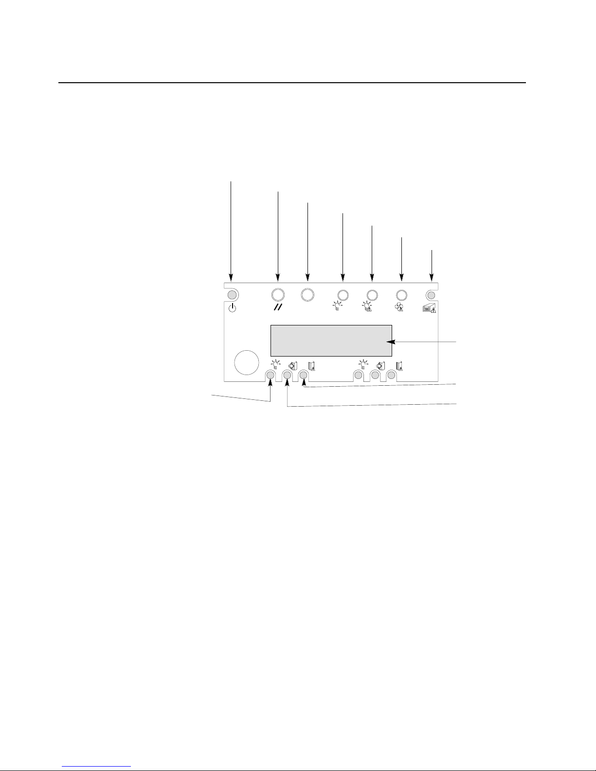
Front view
Power control button: Press this button to turn the server on or off.
Reset button: Press this button to reset the server and run the power-on self-test
(POST).
Initialization button: Press this button to move register information into a file or
output device, provided the operating system supports copying or moving of the
register information.
System power light: When this light is on, power is present in the server. When this
light is off, it indicates that power is turned off or the power source is disrupted.
Power failure light: When this light is flashing, it indicates that the power source
failed. When this light is on, it indicates that the power source experienced a
catastrophic failure.
Fan failure light: When this light is flashing, it indicates that a fan has failed.
Hot-plug adapter failure light: When this light is on, it indicates that a hot-plug
adapter has failed.
Operator information panel: System monitor information appears on this display.
Hard disk drive failure light: When this light is on, a hard disk drive has failed. When
flashing, this light indicates that a drive reset is in progress.
PWR ACTIVE FAIL PWR ACTIVE
ACTIVE
FAIL
POWER RESET INIT
SYS
SYS
PWR FAN GEN-
754499-
LCD DISPLAY
Power control button
Reset button
Initialization button
System power light
Power failure light
Fan failure light
Hot-plug adapter failure ligh
t
Operator
information panel
Hard disk drive
failure light
Hard disk drive
activity light
Hard disk drive
power-on light
Page 22

8 xSeries 380: User’s Reference
Hard disk drive activity light: When this light is on, the server is accessing the hard
disk drive.
Hard disk drive power -on light: When this light is on, power to the hard disk drive is
present.
CD eject/load button: Press this button to eject or retract the CD tray so that you can
insert or remove a CD.
CD activity light: When this light is on, the CD drive is being accessed.
Front panel: The front panel contains status lights.
Diskette drive activity light: When this light is on, the diskette drive is being
accessed.
Diskette eject button: Press this button to eject a diskette from the drive.
Power supply failure light When this light is on, the power supply has failed. When
this light is blinking, the power supply has reached its current limit of power output
Power supply predictive failure light: When this light is blinking, the power supply
is about to fail.
Power supply activity light: When this light is on, the power supply is functioning
properly. When this light is blinking, the power supply is in standby mode.
PWR ACTIVE FAIL PWR ACTIVE FAI L
POWER RESET INIT
SYS PWR
PWR
FAN GEN-
754499-
LCD DISPLAY
CD eject/load
button
CD activity light
Front panel
Diskette drive
activity light
Diskette drive
eject button
Power supply
activity light
Power supply
failure light
Power supply
predictive failure
light
Page 23
Chapter 1. Introducing the IBM xSeries 380 server 9
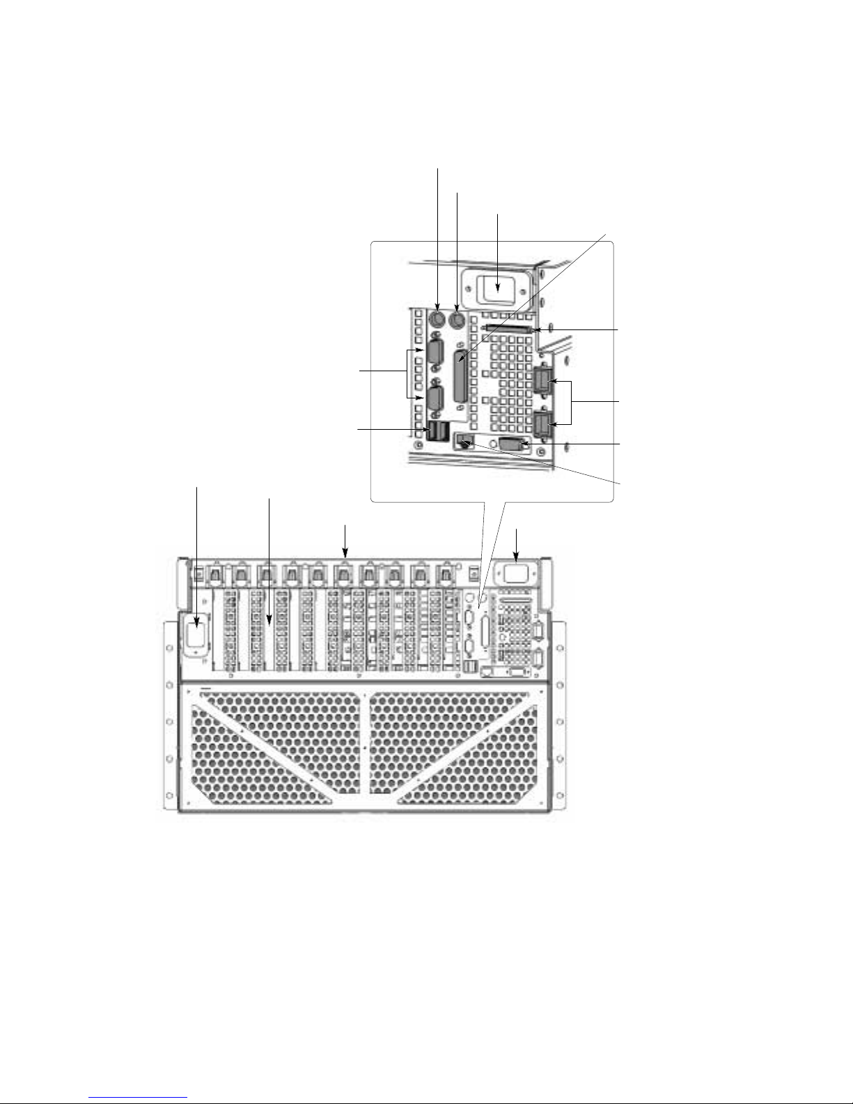
Rear view
USB ports: Use this port to connect Universal Serial Bus devices to the serv er.
Serial ports: Use this port to connect modems or other serial devices to the server.
Keyboard port: Use this port to connect the keyboard to the server.
Auxiliary-device (pointing device) port: Use this port to connect a mouse or
pointing device to the server.
Power cord connector: There are two power cord connectors. These connectors
connect the two power cords to the server.
Power cord connector
Expansion slot
Hot-plug PCI status lights
Power cord connector
Keyboard port
Auxiliary-device (pointing device) port
Power cord connector
Parallel port
External SCSI connector
ICMB ports # 2 - top
# 1 - bottom
Video port
Ethernet port
USB ports
Serial ports A - top
B - bottom
Page 24

10 xSeries 380: User’s Reference
Parallel port: Use this port to connect parallel devices to the server.
External SCSI con nec tor : Use this connector to attach external SCSI devices to the
server.
ICMB ports: Use these ports to connect the Intelligent Chassis Management Bus and
external bus for passing management information between servers.
Video port: Use this port to connect the monitor to the server.
Ethernet port: Use this port to connect the server to an Ethernet network.
Hot-plug PCI status lights: These lights display the status of the PCI adapter
installed in the expansion slot.
Expansion slots: These expansion slots are for PCI adapters. These slots are
numbered 1 through 10 from right to left as you are facing the rear of the server.
Page 25

© Copyright IBM Corp. 2001 11
Chapter 2. Turning on the server
This chapter provides instructions on how to start your server f or the first time, starting
the server after turning it off, and how to turn off the server.
Turning on the server for the first time
Starting the server for the first time involves plugging the two power cables of your
server into a power distribution unit (PDU) and configuring the system before installing
and starting the operating system. Packaged with your server are two power cables to
connect your server to a PDU. You can use one of the following PDU options:
• NetBAY Front-end Power Distribution Unit
• NetBAY Server Dual-cord Power Distribution Unit
• NetBAY Rack Power Distribution Unit
If you choose to plug your server into outlets, refer to “Power cords” on page 91 for
information.
The first time you start the server, you will need to run the BIOS Setup utility, set the
correct date and time, and then let the server run its power-on self-test (POST) and
pass control to the boot manager. For more information, refer to “Using the Extensible
Firmware Interface (EFI) boot manager” on page 24.
Complete the following steps to start your server for the first time:
1. Make sure that all external devices, such as the monitor, keyboard, and mouse
are connected to the server.
2. Remove the drive protection card from the LS120 diskette drive.
3. Plug one end of the two power cables into the server. You must plug a power
cable into each power supply.
4. Plug the opposite end of the two power cables into a PDU. Alternatively, use
optional power cords (see “Power cords” on page 91) to plug the server directly
into the power source.
5. Turn on the monitor by pressing the monitor power-on button.
6. Press the power-control button on the front of the server.
7. Insert the installation CD for your operating system.
Notes:
a. Before you can use your computer, you must obtain and install an operating
system. Refer to the information provided with your operating system for
installation instructions.
b. If you do not insert the CD in time, the system will not recognize the CD and
you will need to restart the server.
8. When the startup process is complete, refer to the documentation that comes with
your operating system for instructions on how to complete the installation.
Page 26
12 xSeries 380: User’s Reference
Turning on the server
This section provides information about how to turn on the server again after the initial
startup has been completed.
Complete the following steps to start the server:
1. Verify that the power cords are plugged into a PDU.
2. Turn on the monitor by pressing the monitor power-on button.
3. Press the power-control button on the front panel of the server. See “Server
controls and indicators” on page 7 for the location of this button.
Attention: If the following message displays during POST, press Reset before
continuing system startup:
Turning off the server
Statement 5
CAUTION:
The power control button on the device and the power switch on the power
supply do not turn off the electrical current supplied to the device. The device
also might have more than one power cord. T o remove all electrical current fro m
the device, ensure that all power cords are disconnected from the power
source.
ERRORS FOUND IN MEMORY SUBSYSTEM, FAILING ROWS WILL BE MAPPED OUT ON THE NEXT
RESET. IT IS STRONGLY SUGGESTED THAT YOU RESET THE SYSTEM NOW.
ALLOWING THE SYSTEM TO CONTINUE TO BOOT MAY RESULT IN UNSTABLE SYSTEM BEHAVIOR
AND/OR HARD DISK CORRUPTION
Hit F1 to load defaults or F2 to run setup or ESC to continue
1
2
Page 27

Chapter 2. T urning on the server 13
Complete the following steps to turn off the server:
Note: Turning off the server refers to the act of disconnecting the server from the
power source.
1. Refer to your operating system documentation for the proper procedure to shut
down the operating system.
Note: Each operating system is different. Some will allow an immediate
shutdown; others require an orderly shutdown procedure.
2. Press and hold the power-control button on the front of the server for several
seconds. This will put the server into standby mode.
3. Disconnect the server from the power source.
Note: After you turn off the server, wait at least 5 seconds bef ore you turn on the
server again.
Standby mode
Standby puts the server into a wait state. When in a wait state, the server is not
running the operating system, and all core logic is shut down except for the service
processor.
Complete the following steps to put the server into the standby mode:
1. Refer to your operating system documentation for the proper procedure to shutdown the operating system.
Note: Each operating system is different. Read all the documentation about
shutting down the operating system before continuing.
2. Press the power-control button on the front of the server.
Page 28

14 xSeries 380: User’s Reference
Page 29

© Copyright IBM Corp. 2001 15
Chapter 3. Arranging your workspace
To get the most from your server, arrange both the equipment you use and your work
area to suit your needs and the kind of work you do. Your comfort is of foremost
importance, b ut light sources, air circulation, and the location of electrical outlets also
can affect the way you arrange your workspace.
Comfort
Although no single working position is ideal for everyone, here are a few guidelines to
help you find a position that suits you best.Sitting in the same position for a long time
can cause fatigue. A good chair can make a big difference. The backrest and seat
should adjust independently and provide good support. The seat should have a
curved front to relieve pressure on the thighs. Adjust the seat so that your thighs are
parallel to the floor and your feet are either flat on the floor or on a footrest.
When using the keyboard, keep your forearms parallel to the floor and your wrists in a
neutral, comfortable position. Try to keep a light touch on the keyboard and your
hands and fingers relaxed. You can change the angle of the keyboard for maximum
comfort by adjusting the position of the keyboard feet.Adjust the monitor so the top of
the screen is at, or slightly below, eye level. Place the monitor at a comfortable
viewing distance, usually 51 to 61 cm (20 to 24 in.), and position it so you can view it
without having to twist your body. Also position other equipment you use regularly,
such as the telephone or a mouse, within easy reach.
Glare and lighting
Position the monitor to minimize glare and reflections from overhead lights, windows,
and other light sources. Even reflected light from shiny surfaces can cause annoying
reflections on your monitor screen. Place the monitor at right angles to windows and
other light sources, when possib le. Reduce overhead lighting, if necessary, by turning
off lights or using lower wattage bulbs. If you install the monitor near a window , use
curtains or blinds to block the sunlight. You might have to adjust the Brightness and
Contrast controls on the monitor as the room lighting changes throughout the
day.Where it is impossible to avoid reflections or to adjust the lighting, an antiglare
filter placed over the screen might be helpful. However, these filters might affect the
clarity of the image on the screen; try them only after you have tried all other methods
of reducing glare.
Dust buildup compounds problems that are associated with glare. Remember to clean
your monitor screen periodically using a soft cloth that is moistened with a
nonabrasive liquid glass cleaner.
Page 30

16 xSeries 380: User’s Reference
Air circulation
Your server and monitor produce heat. Your server has one or more fans that pull in
fresh air and force out hot air. The monitor lets hot air escape through vents. Blocking
the air vents can cause overheating, which might result in a malfunction or damage.
Place the server and monitor so that nothing blocks the air vents; usually, 15 cm (6
inches) of air space is sufficient. Also, make sure that the vented air is not blowing on
someone else
Electrical outlets and cable lengths
The location of electrical outlets and the length of power cords and cables that
connect to the monitor, printer, and other devices might determine the final placement
of your server.
When arranging your workspace:
Avoid the use of extension cords. When possible, plug the PDU power cords
directly into electrical outlets.
Keep power cords and cables neatly routed away from walkways and other areas
where they might get kicked accidentally.
For more information about power cords, see “Power cords” on page 91.
Page 31

© Copyright IBM Corp. 2001 17
Chapter 4. Configuring your server
The following configuration utilities are provided with your server.
• BIOS Setup Utility
This program is part of the basic input/output system (BIOS) that comes with your
server. Use this program to configure the serial and parallel ports, change the drive
startup sequence, set the date and time, and set passwords.
• Extensible Firmware Interface (EFI) boot manager
This program controls the startup environment. After you turn on the server, this
program offers you a choice of startup options. For example, you can start to the EFI
shell, to an operating system located on the network or on media, or to the Boot
Maintenance Menu.
• QLogic SCSI Utility
You can use this utility to configure the devices that are attached to the integrated
SCSI controller. Use this program to change default values, resolve configuration
conflicts, and perform a low-level format on a SCSI hard disk.
• Firmware Update Utility
You can use this utility to upgrade the firmware that controls the Baseboard
Management Controller (BMC), the Hot-Swap Controller (HSC), the Chassis Bus
Controller (CBC), and the system BIOS.
• System Event Log Viewer Utility
You can use this utility to view the System Event Log. The BMC logs system platform
management events and logs the events in the System Event Log (SEL). System
platform management events include over-temperature conditions, over-voltage
conditions, and fan failure.
• Server Management Configuration Utility
You can use this utility to view or modify the serv er management firmware
configuration data. The firmware configuration data is maintained on the BMC.
Page 32

18 xSeries 380: User’s Reference
Using the BIOS Setup Utility program
This section provides the instructions needed to start the BIOS Setup Utility program
and descriptions of the available menu choices.
Starting the BIOS Setup Utility program
To start the BIOS Setup Utility program:
1. Turn on the server.
2. Press F2 to start the BIOS Setup Utility program.
Note: If you have set both levels of passwords (user and supervisor), you must
type the supervisor password to access the full BIOS Setup menu.
Follow the instructions that appear on the screen.
Choices available fro m the BIOS Setup main menu
From the BIOS Setup Utility Main menu, you can select settings that you want to
change.
Note: The choices on some menus might differ slightly, depending on the BIOS
version in your server.
The following table describes the choices available from the Main menu:
Menu item Default value Description
BIOS Version [bios_version_number] The currently installed
version of BIOS. You cannot
change this va lue. It appears
for informational purposes
only.
Processor Type [Intel Itanium processor] The processor type. You
cannot change this value. It
appears for informationa l
purposes only.
Processor Retest [Disabled] Enabled The system will activate and
retest all processors on the
next syste m start, if Enabled.
This option will be
automatically set to Disabled
on the next system start.
Language [English (US)]
Francais (FR)
Deutsch (DR)
Italiano (IT)
Espanol (SP)
The default la nguage used b y
the BIOS.
System Time [hh:mm:ss] The time in
hour:minute:second format.
System Date [day mm/dd/yyyy] The day and date in
month/day/year format.
Page 33

Chapter 4. Configuring your server 19
The following table describes the choices available from the Advanced menu.
Primary menu Item submenu Item value Description
Boot Configuration Plug & Play O/S [No] Yes Configures boot settings. If
the operating system
supports Plug and Play
operation, set this value to
Yes.
Reset Config Data [No] Yes Resets the configuration data
after a restart operation.
Numlock [Off] On Locks the number keypad.
ADM Graphics
Mode
[Disabled] Enabled Enables or disables the ADM
graphics mode.
Peripheral
Configuration
Serial Port A [Auto]
Enable
Disable
Determines serial port A
configuration at startup.
Auto Automatically
determine the base
I/O address and
interrupt to use for
the port.
Enable Requires you to
supply the base I/O
address and the
interrupt value.
Disable Causes the server
to disable the port.
Serial Port B [Auto]
Enable
Disable
Determines serial port B
configuration at startup.
Auto Automatically
determine the base
I/O address and
interrupt to use for
the port.
Enable Requires you to
supply the base I/O
address and the
interrupt value.
Disable Causes the server
to disable the port.
Parallel Port [Auto]
Enable
Disable
Determines parallel port
configuration at boot time.
Auto Causes the server
to determine the
base I/O address
and interrupt to use
for the port.
Enable Requires you to
supply the base I/O
address and the
interrupt value.
Disable Causes the server
to disable the port.
Page 34

20 xSeries 380: User’s Reference
Peripheral
Configuration
Mode [Bi-directional]
Output Only
EPP
ECP
Defines the tran sf er mode f or
the parallel port.
Bi-directional
Enables data
transfer to and from
the server.
Output Enables data
transfer from the
server only.
EPP Specifies Enhanced
Par all el Port mode .
ECP Specifies Enhanced
Port mode.
Onboard SCSI [Enabled]
Disabled
Enables or disables the
onboard SCSI.
Onboard NIC [Enabled]
Disabled
Enables or disables the
onboard network interface
controller (NIC) during the
operation of the EFI shell.
This value has no effect on
the operating system.
Primary menu Item submenu Item value Description
Page 35

Chapter 4. Configuring your server 21
IDE Configuration IDE Controller [Both]
Disabled
Primary
Secondary
Selects the IDE controller
and hard disk drive type
installed in your sy st em.
Both Enables both IDE
controllers.
Disabled Disables the
integrated ID E
controller.
Primary
Enables only the
primary controller.
Secondary
Enables only the
secondary
controller.
Hard Disk PreDelay
[Disabled]
Enabled
[Disabled]
Enabled
Configures the hard disk pre-
delay.
Enabled Causes the BIOS
to insert a delay
before attemp ting to
detect IDE drives in
the system.
Disabled Disables the pre-
delay.
Primary IDE
Master
[drive_id]
Not Installed
A drive-specific identi fier for
the primary IDE master
device currently installed in
the system. Click on the
value to display su b-menu
items:
Type Specifies how the
server identifies the
device
(automatically or as
an ATPI device).
Use ARMD Drive As
Specifies how to
use the device
(diskette drive or
hard disk drive)
Secondary IDE
Master
[drive_id]
Not Installed
A drive-specific identi fier for
the secondary IDE master
device currently installed in
the system. Click on the
value to display a sub-menu
item:
Type Specifies how the
server identifies the
device
(automatically or as
an ATPI device).
Primary menu Item submenu Item value Description
Page 36

22 xSeries 380: User’s Reference
The following table describes the choices available from the Security menu.
Chipset
Configuration
Request Bus
Parking
[Disabled]
Enabled
Defines whether to park on
the system bus.
BINIT Input [Disabled]
Enabled
Enables all host bus agents
to enable bus initialization
(BINIT) observation logic.
In-Order Queue
Depth
[08] Defines the in-order queue
depth. When set to 1, all
agents on the host bus limit
their in-order queue depth to
1.
BSP Jumper
Selected
[Disabled] Enabled
CPU Work
Arounds
[Auto] Manual Defines Processor Dispersal,
DET stalls, and other
processor settings.
Memory Rela ted
Items
[Disabled] Enabled Defines Syste m ECC, Base
Memory Test Interval,
Defectiv e DIMM Map out, and
Clear Bad Memory Row.
Event Log
Configuration
Event Logging [Enabled] Disabled Enables or disables logging
of system events.
Enable BERR [Enabled] Disabled En ables or d isables b us error
(BERR) ev ent gen er ati on.
Enable SERR [Enabled] Disabled Enables or disables PCI
system error (SERR) event
generation.
Enable PERR [Enabled] Disabled Enables or disables PCI
parity error (PERR) event
generation.
Enable BINIT [Enabled] Disabled Enables or disables BINIT
event generation.
Enable HostBus
DATA ERROR
[Enabled] Disabled Enables or disables
processor data error
checking.
Enable HostBus
ADDR PARITY
[Enabled] Disabled Enables or disables
processor Address Parity
checking
Clear All MCA
Records
[Disabled] Enabled Enables or disables the
logging of MCA records on
NVRAM.
Menu item Default value Description
Administrator Password Is [Not Installed]
administrator_password
The current administrator
password. To set the
administrator password, use
the Set Administrator
Password menu item.
User Password Is [Not Installed]
user_password
The current user password.
To set the user password,
use the Set User Password
menu item.
Primary menu Item submenu Item value Description
Page 37

Chapter 4. Configuring your server 23
Setting the administrator passw ord. You can set the administrator password so that
only authorized personnel can change configuration inf ormation from within the BIOS
Setup Utility. The keyboard and mouse remain locked until you type the correct
password. You can use any combination of up to seven characters (A-Z, a-z, 0-9, and
blanks) for your administrator password. Keep a record of your password in a secure
place.
Note: Only a qualified service technician can delete the administrator password.
Setting the user password. This password is set for each user, so that the
administrator can control permissions and configuration options for each user. You
can use any combination of up to seven characters (A-Z, a-z, 0-9, and blanks) for your
user password.
The following describes the choices available from the System Management menu.
The following describes the choices available from the Exit menu.
Set Administrator Password Not applicable Define the administrator
password.
Set User Password Not applicable Define the User password
Menu item Default value Description
Console Redirection Not applicable Configures the server for
console redirection.
Service Boot [Disabled]
Enabled
Starts the server in Service
Partition Boot mo de . This item
will be automatically reset to
Disabled on the next sy ste m
start.
Menu item Description
Exit Saving Changes Exit from Setup with or without saving your
changes in CMOS.
Yes Saves your changes and exits from
the utility
No Discards your changes and exits
from the utility
Exit Discarding Changes Exit from Setup with or without discarding
your changes.
Yes Discards your changes and exits
from the utility.
No Saves your changes and exits from
the utility.
Load Setup Defaults Load Setup with factory defaults.
Yes Loads Setup values from a file
previously saved through the Save
Custom Defaults menu item. You
must specify the file name.
No No action.
Menu item Default value Description
Page 38

24 xSeries 380: User’s Reference
Using the Extensible Firmware Interf ace (EFI) boot manager
You can use the EFI boot manager to configure a variety of boot options including
booting to an external device as well as to a specific file.The following table provides a
summary of the actions available from the EFI boot manager:
Load Custom Defaults Load Setup with custom defaults.
Yes Loads Setup values from a file
previously saved through the Save
Custom Defaults menu item. You
must specify the file name.
No No action.
Save Custom Defaults. Save the current se t of v al ues into a file tha t
you can later load using the Load Custom
Defaults menu item.
Yes Writes setup values to a file you
specify.
No No action.
Discard Changes Discard the changed values you have
accumulated during this Setup session.
Yes Discards the Setup values for the
current Setup Utility session
No No action.
Menu item Description
Action Description
Boot from a File Auto ma tic all y adds EFI applications as boot options or enables
you to boot from a specific file.
Add a Boot Option Adds a boot option to the EFI boot manager. You specify the
option by pr ovidi ng the name o f the EF I ap plicatio n. Alon g wit h
the name, you can also provide either ASCII or UNICODE
arguments the file might use.
Delete Boot Options Enables you to delete a specific boot option or al l boot options.
Change Boot Order Enables you to control the relative order in which the EFI boot
manager attempts boot options. For help on the control key
sequences you need for this option, refer to the help menu.
Enables you to select a boot option to use one time (the next
boot operation).
Manage Boot Next
Setting
Enables you to select a boot option to use one time (the next
boot operation).
Set Automatic Boot
Timeout Value
Enables y ou to defin e the v alue in sec onds that pa ss bef ore t he
system automatically boots without user intervention. Setting
this value to zero disables the timeout feature.
Page 39

Chapter 4. Configuring your server 25
Using the Extensible Firmware Interface (EFI) shell
Use the EFI shell to load device drivers, start EFI applications, and start (boot) the
network operating system. In addition, the EFI shell also provides a set of basic
commands to manage files and sy s tem environment variables.
In addition, with the EFI shell, you can create your own EFI shell commands and EFI
applications. For detailed information about the EFI shell, its commands, and the
ability to develop applications, refer to the EFI Developer’s Guide. Find the guide at
the following World Wide Web address:
http://developer.intel.com/technology/efi/downsource.htm.
Click EFI sample implementation source code and select the Microsoft
®
Word file
Efi_dg.doc in the Notes folder.
Select Active Console
Output Devices
Enables you to display the list of available console output
devices, as contained in the ConOutDev list. You can se le ct or
deselect additio nal outp ut co ns ole s from thi s menu. Note: The
Boot Maintenance Mana ger performs log ic checking to ensure
that you choos e a lega l ensem b le of de v ices . F or example, the
manager does not a llo w y ou to ch oose two di ff e rent m essag ing
devices, such as PC-ANSI and VT-100, to be active consoles
on a given UART.
Select Active Console
Input Devices
Enables you to display the list of available console input
devices, as contained in the ConInDev list and the subset
detailed in the ConIn variable.
Select Active Error
Devices
Enables you to display the list of available error devices as
contained in the ErrOutDev list and the subset detailed in the
ErrOut variable.
Note: The active error devices are essentially a type of
console output device whose only traffic includes error
messaging.
Cold Reset Enables you to perform a platform-specific cold reset of the
system.
Note: A cold reset typically means a full platform reset.
Exit Returns control to the EFI boot manager main menu. This will
display the active boot devices, including a possible integrated
EFI shell (if the implementation is so constructed).
Action Description
Page 40

26 xSeries 380: User’s Reference
Using the QLogic SCSI Utility
Use the QLogic SCSI Utility to configure the SCSI capabilities of the xSeries 380
server. You run this utility during the restart operation before the BIOS Setup Utility. T o
enter the QLogic SCSI Utility, perform the following procedure:
During the system reset performed after you exit from the BIOS Setup Utility, watch
the monitor for the prompt to start the QLogic Setup Utility.When you see the prompt
for th e QLogic Setup Utility, press Alt+Q.
Using the Firmware Update Utility
The Firmware Upgrade Utility is an EFI program that updates the following server
code:
• Baseboard Management Controller (BMC)
• Hot-Swap Controller (HSC)
• Chassis Bridge Controller (CBC)
• BIOS
For the most recent firmware downloads, update utilities, and instructions, go to the
IBM Personal Computing Web page at http://www.ibm.com/pc/support, and download
the latest level of BIOS and firmware code. The README.TXT file in the download
package contains the instructions for using the utility.
Using the SELView Utility
Use the SELView Utility to perform the following tasks:
• Examine all System Event Log (SEL) entries
• Examine previously stored System Event Log entries from a file
• Save the System Event Log entries to a file
• Clear the System Event Log entries from the nonvolatile storage area
• Sort the SEL records by various fields such as Timestamp, Sensor Type Number,
Event Description, and Generator ID
Note: For the latest version of the utility, go to the IBM Personal Computing Web
page at http://www.ibm.com/pc/support.
If you suspect a problem with your server, run this utility and save the log file. Call for
service and refer the servicer to the log file for information. To use the SELView Utility ,
do the following:
1. Insert the System Utilities CD into the CD-ROM drive.
Note: You can run the utility directly from the System Utilities CD or from a
diskette you create from the CD. If you choose to run the utility from a
diskette, follow the instructions in the READ.TXT file on the CD.
2. Type the following command from the EFI shell prompt:
issue: map -r
3. Locate the FSx where x is the CD-ROM drive (FF).
4. Issue FSx: where x is the CD-ROM drive.
Page 41

Chapter 4. Configuring your server 27
5. Type the following: CD selview
6. Run the utility by typing the following command:
Selview
You can select the following actions:
File Open and save System Event Log files. You can also exit from the utility from
this menu.
SEL Manage System Event Log files by reloading data, displaying properties,
clearing log entries, and sorting files by various fields.
Help Provides information on the utility.
Using the Server Management Configuration Utility
Use the Server Management Configuration Utility to perform the following tasks:
• Configure power restoration policies when the system loses AC power
• Set the accelerated cool-down timeout
• Set the Fault Resilient Boot (FRB) time-out
• Enable or disable Platform Event Filtering (PEF) and Platform Event Paging
(PEP)
• Configure the Advanced Configuration and Power Interface (ACPI) features
Note: For the latest version of the utility, go to the IBM Personal Computing Web
page at http://www.ibm.com/pc/support.
To use the Server Management Configuration Utility, do the following:
1. Insert the System Utilities CD into the CD-ROM drive.
Note: You can run the utility directly from the System Utilities CD or from a
diskette you create from the CD. If you choose to run the utility from a
diskette, follow the instructions in the READ.TXT file on the CD.
2. Type the following command from the EFI shell prompt:
issue: map -r
3. Locate the FSx where x is the CD-ROM drive (FF).
4. Issue FSx: for the CD-ROM drive.
5. Type the following: CD SMConfig
6. Run the utility by typing the following command:
SMConfig
The following table provides a summary of the actions available from the utility main
menu.
Menu item Description
File open Opens a different .ini file of configuration data.
Config Select from a dynamic list of options for the configuration
classes in the current .ini file.
Page 42

28 xSeries 380: User’s Reference
Platform setup Configures the platform-specific feature.
Accelerated cool down
Enables the s ystem to cool down more rapidly
when the system is powered off.
Power setup Configures power features.
Power restore policy
Defines activity when the s ys tem los es an d the n
regains AC power.
Power restore delay
The delay in seconds before the power restore
policy is activated.
Power cycle delay
The amount of time the system will not respond
to the front power-on button.
Fault resilient booting setup Enables or disables a multiprocessing system to startup
the system, if the bootstrap processor (BSP) fails.
FRB3 The level of f ault resilien t booting in w hich a timer
is started at system startup or system hard reset.
ACPI Configures ACPI features.
Button model
Defines the model of power-on button.
State notify
Determines if other server management
controllers installed in the server will be notified
of ACPI changes.
Fan control
Defines the operation of the fans when the
system enters standby mode.
Platform event filtering setup Configures the actions to take during a platform event.
PEF enable
Enables or disables the platform event filter
(PEF).
PEP actions
Enables or disables platform event paging
actions when an event filter is triggered.
Logging enabled
Enables or disabled system event logging when
an event filter is triggered.
Power down
Enable or disable system power off during an
event.
Reset Enables or disables a system reset when an
event is triggered.
Power cycle
Enables or disables sending a LAN alert
message when an event is triggered.
Filter entries
Enables or disables pre-configured event filters.
Menu item Description
Page 43

Chapter 4. Configuring your server 29
Platform event paging setup Configures platform event paging features.
Blackout period
The amount of time between telephone pages.
Modem page string
The paging service number and the message
character string.
Emergency management port
(EMP) setup
Enables remote server management over a modem or a
direct serial connection.
Access mode
Defines EMP port access.
Restricted access mode
Enables or disables restricted ac cess mode.
Connection mode
Configures the method of connection to the port.
Data carrier detect mode
Enables or disables monitoring of the data
carrier detect signal.
Baud rate
Configures the maximum rate that data is
transmitted through the EMP port.
Flow control
Enables or di sables the flow control.
Modem Init string
Defines the modem initialization string.
Modem hangup string
This string is sent to the modem when the EMP
ends the session.
Modem ESC sequence
The value sent to the modem before sending a
command string to the modem.
Modem phone number
The telephone num be r of the modem connected
to the server.
Set password
Defines the password to restrict EMP access
through the direct serial connection or modem.
Menu item Description
Page 44

30 xSeries 380: User’s Reference
Direct platform control/LAN
setup
Configure direct platform control/LAN features.
LAN access mode
Defines the remote access mode.
Host IP address
The logical or Web address of the server.
Subnet mask
The logical or We b address of the server subnet .
The mask determines if the alert destination is
the local subnet or a noth er s ub net rel ative to the
server.
Gateway IP address
The IP address of the gateway, or router system
for the subnet.
Alert IP address
The logical or Web address of the systems to
which an alert message will be sent.
SNMP community string
Defines the community field in the header of the
SNMP trap sent for a LAN alert.
Menu item Description
Page 45

© Copyright IBM Corp. 2001 31
Chapter 5. Installing options
This chapter provides the basic information that is needed to install hardware options
and components in your server.
For a list of supported options for your server, see the ServerProven
®
list at the
following World Wide Web address: http://www.ibm.com/pc/compat/.
Some options and components must be installed or replaced only by trained service
personnel.
You can install or replace the following options and components:
• 172-mm fan
• 120-mm fan
• Hard disk drive
• PCI adapters in slots 3 through 10
• Power supply
Trained service personnel only can install or replace the following components:
• Microprocessor
• Memory
• Legacy I/O board
Statement 14
CAUTION:
Hazardous voltage, current, and energy levels might be present. Only a
qualified service technician is authorized to remove the covers where the
following label is attached.
Page 46

32 xSeries 380: User’s Reference
Before you begin
Before you begin to install options in your server, read the following information:
• Become familiar with the safety and handling guidelines provided in the Safety
Information book, the requirements specified in “Safety information” on page 34,
and the information in “Handling static-sensitive devices” on page 33. These
guidelines will help you work safely while working with your server or options.
• Make sure that you have an adequate number of properly grounded electrical
outlets for your server, monitor, and any other options that you intend to install.
• You do not need to turn off the server to install or replace hot-swap power
supplies, hot-swap drives, hot-swap fans, or hot-plug PCI adapters.
• Back up all important data before you make changes to disk drives.
For a list of supported options for the xSeries 380, refer to
http://www.ibm.com/pc/us/compat on the World Wide Web.
System reliability considerations
Attention: The operating temperature of the server, when installed in an equipment
rack, must not go below 10° C (50° F) or rise above 35° C (95° F). Extreme
fluctuations in temperature can cause a v ariety of problems in your server.
The equipment rack must provide sufficient airflow to the front of the server to
maintain proper cooling. It must also include ventilation sufficient to exhaust a
maximum of 6174 Btu per hour for the server. The rack that is selected and the
ventilation that is provided must be suitable to the environment in which the server will
be used.
To help maintain proper cooling and system reliability, ensure that:
• Each of the drive bays has a drive installed.
• Each of the power supply bays has a power supply installed.
• A removed hot-swap drive is replaced within 10 minutes of removal.
• Cables for optional adapters are routed according to the instructions that are
provided with the adapters.
• A failed fan is replaced within 48 hours.
Page 47

Chapter 5. Installing options 33
Working inside the server with the power on
Your server supports hot-plug devices and is designed to operate safely while turned
on with the cover removed. Follow these guidelines when you work inside a server
that is turned on:
• Avoid loose-fitting clothing on your forearms. Button long-sleeved shirts before
working inside the server; do not wear cufflinks while you are working inside the
server.
• Do not allow your necktie or scarf to hang inside the server.
• Remove jewelry, such as bracelets, necklaces, rings, and loose-fitting wrist
watches.
• Remove items from your shirt pocket (such as pens or pencils) that could fall into
the server as you lean over it.
• Take care to avoid dropping any metallic objects, such as paper clips, hair pins, or
screws, into the server.
Handling static-sensitive devices
Attention: Static electricity can damage electronic devices and y our system. T o av oid
damage, keep static-sensitive devices in their static-protective package until you are
ready to install them.
To reduce the possibility of electrostatic discharge, observe the following precautions:
• Limit your movement. Movement can cause static electricity to build up around
you.
• Handle the device carefully, holding it by its edges or its frame.
• Do not touch solder joints, pins, or exposed printed circuitry.
• Do not leave the device where others can handle and possibly damage the
device.
• While the device is still in its static-protective package, touch it to an unpainted
metal part of the system unit for at least two seconds. (This drains static electricity
from the package and from your body.)
• Remove the device from its package and install it directly into your system unit
without setting it down. If it is necessary to set the device down, place it in its
static-protective package. Do not place the device on your system unit cover or on
a meta l t a bl e.
• Take additional care when handling devices during cold weather because heating
reduces indoor humidity and increases static electricity.
Page 48

34 xSeries 380: User’s Reference
Safety information
Before installing this product, read the Safety Information.
Antes de instalar este produto, leia as Informações de Segurança.
Læs sikkerhedsforskrifterne, før du installe rer dette produk t.
Lees voordat u dit product installeert eerst de veiligheidsvoorschriften.
Ennen kuin asennat tämän tuotteen, lue turvaohjeet kohdasta Safety Information.
Avant d'installer ce produit, lisez les consignes de sécurité.
Vor der Installation dieses Produkts die Sicherheitshinweise lesen.
Prima di installare questo prodotto, leggere le Informazioni sulla Sicurezza
Les sikkerhetsinformas jo nen (S afety Information) før du installerer dette produktet.
Antes de instalar este produto, leia as Informações sobre Segurança.
Pred instalací tohoto produktu si prectete prírucku bezpecnostních instrukcí.
Page 49

Chapter 5. Installing options 35
Antes de instalar este producto lea la información de seguridad.
Läs säkerhetsinformationen innan du installerar den här produkten.
Page 50

36 xSeries 380: User’s Reference
Statement 1
DANGER
To connect:
1. Turn everything OFF.
2. First, attach all cables to devices.
3. Attach signal cables to connectors.
4. Attach power cords to outlet.
5. Turn device ON.
To disconnect:
1. Turn everything OFF.
2. First, remove power cords from outlet.
3. Remove signal cables from connectors.
4. Remove all cables from devices.
Electrical current from power, telephone, and communication cables is
hazardous.
To avoid a shock hazard:
• Do not connect or disconnect any cables or perf orm installation, maintenance, or reconfiguration of this product during an electrical storm.
• Connect all power cords to a properly wired and grounded electrical
outlet.
• Connect to properly wired outlets any equipment that will be attached
to this product.
• When possible, use one hand only to connect or disconnect signal
cables.
• Never turn on any equipment when there is evidence of fire, water, or
structural damage.
• Disconnect the attached power cords, telecommunications systems,
networks, and modems before you open the device covers, unless
instructed otherwise in the installation and configuration procedures.
Page 51

Chapter 5. Installing options 37
Statement 3
CAUTION:
When laser products (such as CD-ROMs, DVD drives, fiber optic devices, or
transmitters) are installed, note the following:
• Do not remove the covers. Removing the covers of the laser product could
result in exposure to hazardous laser radiation. There are no serviceable
parts inside the device.
• Use of controls or adjustments or performance of procedures other than
those specified herein might result in hazardous radiation exposure.
Class 1 Laser Product
Laser Klasse 1
Laser Klass 1
Luokan 1 Laserlaite
Appareil A Laser de Classe
1
`
Page 52

38 xSeries 380: User’s Reference
Statement 4
CAUTION:
Use safe practices when lifting.
Statement 5
CAUTION:
The power control button on the device and the power switch on the power
supply do not turn off the electrical current supplied to the device. The device
also might have more than one power cord. To remove all electrical current
from the device, ensure that all power cords are disconnected from the power
source.
≥18 kg (37 lbs)
≥32 kg (70.5 l bs)
≥55 kg (121.2 lbs)
1
2
Page 53

Chapter 5. Installing options 39
Statement 8
CAUTION:
Never remove the cover on a power supply or any part that has the following
label attached.
Hazardous voltage, current, and energy levels are present inside any
component that has this label attached. There are no serviceable parts inside
these components. If you suspect a problem with one of these parts, contact a
service technician.
Statement 13
CAUTION:
Overloading a branch circuit is potentially a fire hazard and a shock hazard
under certain conditions. To avoid these hazards, ensure that your system
electrical requirements do not exceed branch circuit protection requirements.
Refer to the information that is provided with your IBM device for electrical
specifications.
Page 54

40 xSeries 380: User’s Reference
Statement 15
CAUTION:
Make sure that the rack is secured properly to avoid tipping when the server
unit is extended.
Statement 16
CAUTION:
Some accessory or option board outputs exceed Class 2 or limited power
source limits and must be installed with appropriate interconnecting cabling in
accordance with the national electric code.
Page 55

Chapter 5. Installing options 41
Installing hot-swap options
This section contains the information necessary to install, remove, and replace the
hot-swap options and components in your server . The options and components in the
following list are the only options and components that you can install, remove, or
replace. A qualified technician must service all other options and components.
User-replaceable options and components include the following:
• 172-mm fan
• 120-mm fan
• Hard disk drive
• PCI adapters in slots 3 through 10
• Power supply
Replacing a hot-swap 172-mm fan
Your server contains four 172-mm fans, two on each side of the server. The fans are
accessed from the fan-access doors on either side of the server. Each fan contains a
fan-failure light that identifies a failed fan.
Note: The illustrations in this document might differ slightly from your hardware.
Complete the following steps to replace a 172-mm fan:
1. Review the information in “Safety information” on page 34.
Statement 15
CAUTION:
Make sure that the rack is secured properly to avoid tipping when the server
unit is extended.
2. Slide the server out of the rack.
Page 56

42 xSeries 380: User’s Reference
3. Slide the latch on the fan-access door upward, and open the door.
4. Grasp the fan assembly with the finger holes, and pull the fan assembly out of the
server.
Attention: To maintain proper cooling, do not leave the door open for an
extended time.
5. Slide the new fan assembly into place.
6. Close and lock the fan-access door.
7. Slide the chassis bac k into the rack.
Replacing a hot-swap 120-mm fan
Your serv er contains two 120-mm fans, which are accessed from the fan-access door
on the top of the server. Each f an contains a fan-failure light that identifies a failed fan.
Note: The illustrations in this document might differ slightly from your hardware.
Complete the following steps to replace a 120-mm fan:
1. Review the information in “Safety information” on page 34.
Statement 15
CAUTION:
Make sure that the rack is secured properly to avoid tipping when the server
unit is extended.
2. Slide the server out of the rack.
3. Loosen the thumbscrew on the fan-access door, and open the door.
172 mm Fan
Finger hole
Page 57

Chapter 5. Installing options 43
4. Grasp the fan assembly with the finger holes, and pull the fan assembly out of the
server.
Attention: Do not leave the door open for an extended time. Cooling of the
system could be reduced.
5. Slide the new fan-assembly into place.
6. Close the fan-access door, and tighten the thumbscrew.
7. Slide the chassis back into the rack.
Installing a hot-swap hard disk dri ve
Your server supports two 1-inch (26 mm) slim, 3.5-inch hot-swap SCSI hard disk
drives in the hard disk drive bays.
Each hot-swap hard disk drive has three indicator lights: the power-on light, activity
light, and status light. The hard disk drive lights are illustrated and described in
“Server controls and indicators” on page 7. If the amber hard disk drive status light is
lit continuously, that individual drive is faulty and requires replacement. You can
replace a hot-swap drive without turning off the server.
Note: The illustrations in this document might differ slightly from your hardware.
Attention: When you handle static-sensitive devices, take precautions to avoid
damage from static electricity. For details on handling these devices, see “Handling
static-sensitive devices” on page 33.
Note: To maintain proper system cooling, do not operate the server for more than 10
minutes without either a drive or a filler panel installed in each bay.
120 mm Fan
Finger hole
Page 58

44 xSeries 380: User’s Reference
Complete the following steps to install a drive in a hot-swap bay:
1. Review “Before you begin” on page 32.
Note: You do not have to turn off the server to install hot-swap hard disk drives.
2. Align the drive assembly with the guide rails in the bay, and slide the drive into the
bay.
3. Check the hard disk drive indicator lights to verify that the drive is functioning
properly. See “Server controls and indicators” on page 7 for more information.
Attention: Do not press on the perforated metal bracket of the tray when you
push the assembly into the bay.
Replacing a hot-swap power supply
Before you continue with the power-supply replacement procedure, review the
following information.
Attention: To maintain proper system cooling, do not operate the server f or more than
5 minutes without either a power supply or filler panel installed.
Notes:
1. The power-supply bays are, from left to right, 1, 3, 4, and 2.
2. The illustrations in this document might differ slightly from your hardware.
13 42
Page 59

Chapter 5. Installing options 45
Statement 8
CAUTION:
Never remove the cover on a power supply or any part that has the following
label attached.
Hazardous voltage, current, and energy levels are present inside any
component that has this label attached. There are no serviceable parts inside
these components. If you suspect a proble m with one of these parts, contact a
service technician.
The power-supply status indicators provide the following information:
Complete the following steps to replace a power supply:
1. Review the information in “Before you begin” on page 32.
Power on
Predictive
failure
Failure Power-supply status
Off Off Off No power to any power supplies
Off Off On Power-supply failure
Blinking Off Off AC power present/standby output on
On Off O ff DC outputs on and working
On Off Blinking Curre nt lim it
On Blinking Off Predictive failure
Page 60

46 xSeries 380: User’s Reference
2. Press the handle-locking tab to the left, and pull the power-supply handle down.
3. Slide the power-supply out of the server.
4. Remove the new power-supply from the protective packaging, and place it on a
static-protective surface.
5. With the handle in the open position (pulled down), slide the new power supply
into the power-supply bay.
6. Push the handle up and into the locked position.
7. Check the power-supply status indicators to v erify the power supply is functioning
properly.
Replacing a hot-plug PCI adapter
This section provides instructions on replacing a hot-plug PCI adapter.
Notes:
1. You can install hot-plug adapters in slots 3 through 10 only, counting from right to
left while facing the back of the server.
2. Hot-plug operations require operating system support and installation of the
required device drivers. You can determine if IBM has validated an adapter for
hot-plug operation at: http://www.ibm.com/pc/us/compat/hotplug/index.shtml. For
unsupported adapters, refer to the documentation provided with the adapter for
information and support.
Power supply handle
Handle locking tab
Page 61

Chapter 5. Installing options 47
Complete the following steps to replace a hot-plug PCI adapter:
1. Review the information in “Before you begin” on page 32.
Statement 15
CAUTION:
Make sure that the rack is secured properly to avoid tipping when the server
unit is extended.
Statement 16
CAUTION:
Some accessory or option board outputs exceed Class 2 or limited power
source limits and must be installed with appropriate interconnecting
cabling in accordance with the national electric code.
2. Slide the server out of the rack.
3. Loosen the thumbscrews on the rear cover, and open the cover.
Thumb screws
Rear cover
Page 62

48 xSeries 380: User’s Reference
4. Press on the retention mechanism locking tab, and rotate the mechanism out
toward the rear of the server.
5. Remove the adapter from the expansion slot.
6. Insert the new PCI adapter into the expansion slot, and press it firmly into place.
7. Push the retention mechanism locking tab in from the rear of the server until it
locks into place.
Note: Refer to the upper-left corner of the illustration above.
8. Rotate the retention mechanism locking tab on the rear of the expansion slot into
place.
9. Check the status lights above the PCI adapter after it is installed.
Note: If the green status light is lit, power is applied to the adapter , and it is ready
for use. If the amber status light is lit, the adapter might be defective or not
installed properly.
10. Configure the adapter, according to the instructions that come with the adapter.
Retention mechanism
Retention mechanism
locking tab
Retention mechanism
Page 63

Chapter 5. Installing options 49
Input/output ports
This section provides information about the following input/output (I/O) ports on the
rear of your server:
• One video port
• One auxiliary pointing-device (mouse) port
• One keyboard port
• One paral lel port
• Two serial ports
• Two Universal Serial Bus (USB) ports
• One external SCSI port
Video port
The integrated ATI RAGE 128VR 64-bit SVGA chip contains an SVGA controller that
is fully compatible with industry video standards. The standard system configuration
comes with 16 MB of video memory. You cannot add video memory to this system.
There is one video port connector on the system board.
The following table shows the pin-number assignments for the video connector on the
system board.
Pin Signal Pin Signal
1 Red 9 Not connected
2 Green 10 Ground
3 Blue 11 Not connected
4 Not connected 12 Display data channel data
5 Ground 13 Horizontal synchronization
6 Ground 14 Vertical synchronization
7 Ground 15 Display data channel clock
8Ground
1
5
1115
Page 64

50 xSeries 380: User’s Reference
Keyboard port
There is one keyboard port on the system board.
The following table shows the pin-number assignments for the keyboard connector on
the system board.
Auxiliary-device (pointing device) port
There is one auxiliary-device (pointing device) port on the system board.
The following table shows the pin-number assignments for the auxiliary-device
connector on the system board.
Pin Signal Description
1 I/O Data
2 N/A Not connected
3 N/A Ground
4N/A +5 V dc
5 I/O Keyboard clock
6 N/A Not connected
6
4
2
1
3
5
Pin Signal Description
1 I/O Data
2 N/A Not connected
3 N/A Ground
4N/A +5 V dc
5 I/O Keyboard clock
6 N/A Not connected
6
4
2
1
3
5
Page 65

Chapter 5. Installing options 51
Parallel port
Your server has one parallel port. The 25-pin connector of the parallel port provides
one IEEE 1284-compatible 25-pin bi-directional EPP. BIOS programming of the Super
I/O registers enables the parallel port and determines the port address and interrupt.
When disabled, the interrupt is available to add-on boards.
The following table shows the pin-number assignments for the parallel-port connector
on the system board.
Pin Signal Pin Signal
1 STROBE_L 10 -Acknowledge
2 Data bit 0 11 Busy
3 Data bit 1 12 Paper end
4 Data bit 2 13 Select
5 Data bit 3 14 -Auto feed
6 Data bit 4 15 -Error
7 Data bit 5 16 -Initial
8 Data bit 6 17 -SLCTIN_L
9 Data bit 7 18-25 Ground
13
1
25
14
Page 66

52 xSeries 380: User’s Reference
Serial ports
Your server has two standard serial (communication) ports: serial port A and serial
port B.
The following table shows the pin-number assignments for the serial-port connectors
on the system board. These pin-number assignments conform to the industry
standard.
Universal Serial Bus (USB) ports
Your server has two Universal Serial Bus (USB) p orts, wh ich are configured
automatically.
Pin Signal Description
1 DCD Data carrier detected
2RXDReceive data
3 TXD Transmit data
4 DTR Data terminal ready
5 GND Ground
6 DSR Data set ready
7 RTS Request to send
8 CTS Clear to send
9 RIA Ring indication active
1
5
69
Pin Signal Description
1 VCC Over current monitor (port 0 or 1)
2 DataL (0 or 1) Differential data line paired with DATAH0
3 DataH (0 or 1) Differential data line paired with DATAL0
4 GND Ground
14
Page 67

Chapter 5. Installing options 53
SCSI port
Your server has one external small computer system interface (SCSI) port.
The QLogic ISP 12160 LVDS SCSI controller supports two LVDS channels. One
channel is used internally to provide support for the internal SCSI drives (connected
to the SCSI backplane). The second L VDS channel is routed to the rear of the chassis
to support external devices.
34
1
68
35
Pin Signal Pin Signal Pin Signal Pin Signal
1 +Data 12 18 Term power 35 -Data 12 52 Term power
2 +Data 13 19 S19 (Reserved) 36 -Data 13 53 Reserved
3 +Data 14 20 Ground 37 -Data 14 54 Ground
4 +Data 15 21 +Attention 38 -Data 15 55 -Attention
5 +Data P1 22 Ground 39 -Data P1 56 Ground
6 +Data 0 23 +Busy 40 -Data 0 57 -Busy
7 +Data 1 24 +Acknowledge 41 -Data 1 58 -Acknowledge
8 +Data 2 25 +Reset 42 -Data 2 59 -Reset
9 +Data 3 26 +Message 43 -Data 3 60 - Message
10 +Data 4 27 +Select 44 -Data 4 61 -Select
11 +Data 5 28 +Control/Data 45 -Data 5 62 -Control/Data
12 +Data 6 29 +Request 46 -Data 6 63 -Request
13 +Data 7 30 +Input/Output 47 -Data 7 64 -Input/Output
14 +Data P 31 +Data 8 48 -Data P 65 -Data 8
15 Ground 32 +Data 9 49 Ground 66 -Data 9
16 S16
(DIFFSENS)
33 +Data 10 50 Ground 67 -Data 10
17 Term power 34 +Data 11 51 Term power 68 -Data 11
Page 68

54 xSeries 380: User’s Reference
Page 69

© Copyright IBM Corp. 2001 55
Chapter 6. Solving Problems
This section provides basic troubleshooting information to help you resolve some
common problems that might occur with your server.
If you cannot locate and correct the problem using the information in this section, refer
to “Getting information, help, and service” on page 76 for more information.
Diagnostic tools overview
The following tools are available to help you identify and resolve hardware-related
problems:
• AMIDiagnostic program
This program is an EFI-based diagnostic program for IBM 64-bit computers with
Intel microprocessors. The AMIDiag has test routines that examine the systems
and subsystems in the server, including all PCI Plug and Play features. AMIDiag
detects, diagnoses, and provides system information about PCI Plug and Play
adapters and devices.
Detailed information about the network environment, CD-ROM drives, SCSI
devices, power-management features, and other system data can be displayed.
The diagnostic program tests the existing system memory and cache memory; it
does not simply report information found in the system BIOS.
Note: The AMIDiag can test up to 64 GB of memory
• Troubleshooting charts
These charts list problem symptoms, along with suggested steps to correct the
problems. See the “Troubleshooting charts” on page 70 for more information.
Page 70

56 xSeries 380: User’s Reference
S
erver Support
After you register and profile, you will be able to:
• Diagnose problems using the IBM Online Assistant
• Participate in the IBM discussion forum
• Receive e-mail notifications of technical updates
related to your profiled products
Register at:
Profile at:
http://www.ibm.com/pc/register
http://www.ibm.com/pc/support
Register and profile your server
Yes
No
No
Phone an
IBM HelpCenter
Use the troubleshooting
information provided with
your server to determine
the cause of the problem
and the action to take.
Flash the latest levels of BIOS,
service processor, diagnostics,
and RAID code.
You can download this code at:
http://www.ibm.com/pc/support
No
No
Yes
Yes
Yes
Check all cables for loose connections
and verify that all optional devices you
installed are on the ServerProven list.
You can view the ServerProven list at:
®
http://www.ibm.com/pc/compat
Server working
properly?
Problem
solved?
Problem
solved?
Problem
solved?
You can view the HelpCenter phone
numbers in the Support Phone List at:
http://www.ibm.com/pc/support
Page 71

Chapter 6. Solving Problem s 57
POST
When you turn on your server, it performs a series of tests to check the operation of
server components and some of the options installed in the server. This series of tests
is called the power-on self-test (POST). The System Abstraction Layer (SAL), BIOS,
and Extensible Firmware Interface (EFI) each perform a segment of the POST.
Note: If you have a power-on password set, you must type the password and press
Enter, when prompted, before POST will continue.
AMIDiagnostic program
Complete the following steps to run the AMIDiagnostic program:
1. Insert the LS120 diskette containing the diagnostic program into the diskette
drive.
2. Boot the system to the EFI shell.
3. Type FS0: and press Enter to select FS0 as the default drive.
4. Type AMIDiag and press Enter to start the diagnostic program.
5. Use the arrow keys or keyboard shortcuts to select the test. See “AMIDiag
Shortcuts” on p age 59 for the keyboard shortcuts.
6. Press Enter to run the test.
Running AMIDiag in batch mode
When your computer is experiencing an intermittent problem that no diagnostic
software test has been able to identify, run the AMIDiag test over an e xtended period
of time. Many computer problems (especially memory problems) are not evident when
a test is run only once. AMIDiag enables you to run diagnostics on only a certain part
of the computer, a specific part of memory, or a specific part of a disk drive. AMIDiag
also enables you to build script (INI) files that contain test configuration information.
After you have created an AMIDiag.ini file, you can run the AMIDiag diagnostic
routines listed in the INI file automatically .
Batch mode steps
Complete the following steps to run the diagnostic program in the batch mode:
1. Select the AMIDiag tests to be run.
2. Select the test parameters, such as the drives, the I/O ports, and other
parameters for each selected test.
Note: These parameters differ for each test.
3. After selecting the test and its parameters, press F10 to run the test and check
that it is configured properly.
4. Save the selected test parameters and tests in an AMIDiag.ini file.
Note: You can run this set of tests at any time.
Page 72

58 xSeries 380: User’s Reference
Error log viewer
AMIDiag enables you to display the error log while still running AMIDiag. The AMIDiag
error log contains all diagnostic errors that AMIDiag has found during the current
AMIDiag session. The error log viewer offers some text search capabilities.
To display the error log, complete the following:
1. Click display error log file on the AMIDiag options menu.
2. Type the name of the error log file.
Note: The default error log name is AMIDIAG.LOG
AMIDiag Menus
The following is a list the available menu choices from the AMIDiag program:
• System
• Memory
• IDE Devices
• Diskette drive (FDD)
• SCSI
• Keyboard (KBD)
• Video
• USB
• Miscellaneous (Misc.)
• User
• Options
The following illustration is a screen shot of the AMIDiag menu choices.
Page 73

Chapter 6. Solving Problem s 59
AMIDiag Shortcuts
The following illustration shows the keyboard shortcuts for the AMIDiag program.
The following table contains the various keyboard shortcut combinations to run certain
AMIDiag tests:
To run the test or test group... Do this
Run all AMIDiag tests. Press F7, then F10.
Run a complete overall system quick test Press F8, then F10.
Run all system board diagnostic tests. Select the System menu. Press F6, then
F10.
Run all memory diagnostic routines. Select the Memory menu. Press F6, then
F10.
Run all IDE drive diagnostic routines. Select the IDE menu. Press F6, then F10.
Run all diskette diagnostic routines. Select the Flopp y m enu. Press F6 , then F1 0.
Run all keyboar d diag nos tic routin es. Sel ect the Keyboard menu. Press F6. Press
F10.
Run all video diagnostic routines. Select the Video menu. Press F6. Press
F10.
Run all serial, parallel, and mouse
diagnostic routines.
Select the Misc. menu. Press F6. Press F10.
Print a report about system configuration
and test errors.
Select the Options menu. Select Generate
Reports. Select the print device.
Exit AMIDiag. Press Esc. Select Yes at the prompt.
Page 74

60 xSeries 380: User’s Reference
Selecting AMIDiag tests
Processor problems
Make sure the computer has the proper
CPU and it is operating properly.
Run the Basic Functio nality test and the CPU
Protected Mode on the System menu.
Check the CPU speed. Run the Processor sp eed tes t on t he Sys tem
menu.
Make sure the computer clock is running
properly.
Run the Timer test and the Real Time Clock
test on the System menu.
Make sure the system configuration is not
corrupted.
Run the CMOS Validity test on the System
menu.
Make sure Plug an d Play devices are
functioning.
Run the Plug and Play test on the System
menu.
Make sure the PCI adapter slots are
functioning correctly.
Run the PCI system test on the System
menu.
Memory problems
Random memory (or performance)
problems occur b ut BIO S POST di d not find
any memory problems.
Run the Pattern test, the Random Pattern
Test and the Cache Memory test on the
Memory menu.
The BIOS finds memory errors or memory
problems occur co nst antl y.
Run the Walking 1s test on the Memory
menu.
Intermittent cache memory problems. Run the Cache Memory test on the Memory
menu.
Identify and report data corruption because
of hardware parity problem s .
Run the Parity test on the Memory menu.
Identify shorts on data lines and data bits
stuck at 0.
Run the Walking 0s test on the Memory
menu.
IDE device problems
Find the data tran sfer rate and track to tra c k
seek time for the hard disk driv e.
Run the Performance test on the DISK IDE
menu.
Determine the drive Seek capability. Run the Seek test on the DISK IDE menu.
Verify the hard drive read function. Run the Read/Verify test on the DISK IDE
menu.
Diskette drive problems
Verify that the floppy drive formats disks
correctly.
Run the Diskette Format test on the FDD
menu.
Verify the floppy drive speed. Run the Drive Speed test on the FDD menu.
Make sure the floppy drive is reading and
writing correctly.
Run the Random R/W test and the
Sequential R/W test on the FDD menu.
Make sure the drive seeks correctly. Run the Elevator Seek test on the FDD
menu.
Keyboard problems
Make sure the keyboard interface works Run the Keyboard Controller test on the
Keyboard Menu.
Page 75

Chapter 6. Solving Problem s 61
Make sure each keyboard key sends the
correct signal to the computer.
Run the Scan/ASCII Code test on the
Keyboard Menu.
Make sure the keyboard LEDs work. Run the Keyboard LED test on the Keyboard
Menu.
SCSI drive problems
Make sure that the SCSI drive is reading
correctly.
Run the SCSI Disk Read test on the SCSI
menu.
Make sure that the SCSI drive is writing
correctly.
Run the SCSI Disk Write test on the SCSI
menu.
Make sure that the SCSI tape drive is
reading correctly.
Run the SCSI Tape Read test on the SCSI
menu.
Make sure that the SCSI tape drive is
writing correctly.
Run the SCSI Tape Write test on the SCSI
menu.
Rewind the tape cartridge in the SCSI tape
drive.
Run the SCSI Tape Rewind test on the SCSI
menu.
CD-ROM drive problems
Make sure that the CD-ROM drive is
reading correctly.
If the computer has a SCSI CD-ROM dri ve,
run the SCSI CD-ROM Read test on the
SCSI menu. If the compute r has an ATAPI or
IDE CD-ROM drive, run the CD Data test on
the IDE menu.
To test the CD-R OM drive tra y, Choose the CD Tray Test on the IDE or SCSI
group menu.
Make sure that the CD-ROM drive can play
audio CDs correctly.
If the computer has a SCSI CD-ROM dri ve,
choose the SCSI CD-ROM Play test on the
SCSI menu.If the computer has an ATAPI or
IDE CD-ROM drive, choose the CD Audio
Test on the IDE menu.
Video problems
Video display problems. Run the Video Memory test on the Video
menu.
Make sure the video display attributes
(blinking, bold, and reverse video) memory
are operating correctly.
Run the Attribute test on the Video menu.
Make sure text displays correctly. Run the 40x25 and 80x25 Display tests on
the Video menu.
Make sure graphics display correctly. Make sure the correct video drivers are
loaded. Run the Video 320x200, 640x200,
640x350, 640x480, and Color tests on the
Video menu.
Make sure Super VGA graphics display
correctly.
Run the VESA Video Mode and VESA Video
Memory test on the Video menu.
Serial port problems
A mouse attached to a serial port does not
work. A device attached to a serial port
does not work.
Run the Serial port test on the Misc. menu.
Page 76

62 xSeries 380: User’s Reference
AMIDiag error codes
This section contains tables showing the error codes that can be generated by some
of the AMIDiag program tests. Locate the test name in the headings to find the correct
list of error codes.
System error codes
Parallel port problems
A printer connected to th e paral lel port does
not work.
Run the Parallel port test on the Misc. menu.
Audio problems
Make sure the speaker attached to your
computer i s working correctly.
Run the PC speaker test on the System
menu.
Make sure the Sound Blaster adapter in
your computer is working.
Run the Sound Blaster test on the Misc.
menu.
Code Explanation Action
3000h Register Bank Switch Failed Call for service.
3001h Register Read/Write Failed
3002h CPU Basic Instruction
Operation Failed
3006h FPU Comparison Error
3010h CPU Speed does not match
expected value
3011h CPU Mode Switching Failed
3020h CPU Basic Compatibility
Test Failed
3022h CPU Protected Mode
Compatibility Test failed
3100h Read/Write test on DMA
controller 1 failed
Call for service.
3101h Read/Write test on DMA
controller 2 failed
3102h Read/Write test on page
registers failed
3111h Enable/Disable of the
interrupt controller failed
3120h The Timer Periodic Interrupt
is not being generated
3121h The Timer is counting at a
slower rate
Page 77

Chapter 6. Solving Problem s 63
Memory error codes
3140h The battery backup unit that
powers CMOS RAM has no
power
Call for service.
00A0h PCI Device Enumeration
Failed
00A1h PCI Device Access Failed
00A2h PCI Configuration Space
could not be verified
1000h MP table failed or Load MP
driver failed
1009h Cache coherency test failed
100Ah Memory consistency test
failed
100Bh I/O access test failed on
processor X at port xxxxh
100Eh CPU speed error 1. Check that the
expected value entered
is correct.
2. Ca ll for service .
1020h CPU functionality test f a ile d Call for service .
00B2h SMBIOS Table Checksum
Invalid
Code Explanation Action
Code Explanation Action
0100h ROM read error.The
diagnostic progra m cou ld
not read from a ROM
location.
Call for service.
0120h Parity error at absolute
memory location xxxx xxxxh.
The diagnostic program
found a parity error at
xxxxxxxxh.
0130h The pattern written at
xxxxxxxxh was qqq qh. The
pattern read back from that
address was pppph.
AMIDiag wrote a pattern to
address xxxxxxxxh. A
different value was read
back.
Page 78

64 xSeries 380: User’s Reference
0131h Parity failure at xxxxxxxxh
during pattern test. While
performing the pattern test
to the specified address,
AMIDiag received a parity
error.
Call for service.
0132h Faulty memory chip on
SIMMM xxxx1. Reseat
Memory DIMMs 2. Replace
Memory Board.
0135h ECC correctable error in
SIMM sockets xxxx/yyyy
0136h ECC uncorrectable error in
SIMM sockets xxxx/yyyy
0137h Error occurred on bank xxx x
interleave yyyy
0140h Failure at addre ss
xxxxxxxxh, bit position bbh.
A failure occurred at the
specified address.
0150h Failure at xxxxxxxxh, bit
position bbh. A failure
occurred at the specified
address.
0170h RAM Refresh is not working.
The system RAM refresh
signal is either not being
generated or the signal is
being generated
sporadically.
0180h The pattern written at
address xxxxxxxxh was
qqqqh. The pattern read
back from that address was
pppph. The diagnostic
program wrote a pattern to
address xxxxxxxxh. When
reading it back, AMIDiag
read a different value from
that same address.
0184h Data bus short found1
0190h Test failed at address
xxxxxxxxh. An unknown
memory error occurred at
xxxxxxxxh.
Code Explanation Action
Page 79

Chapter 6. Solving Problem s 65
IDE CD error codes
IDE DVD error codes
ATAPI remov a bles error codes
Code Explanation Action
0A01h Eject fails on drive x 1. Manually eject media.
2. Retry tray function.
3. Ca ll for service .
0A02h Close failed on drive x
0A03h Sequential data test failed,
Drive x, Sector Y
1. Replace media.
2. Ca ll for service .
0A04h Sequential data test failed,
No data CD in Drive x
0A05h Random data test failed,
Drive x, Sector Y
0A06h Random data test failed, No
data CD in Drive x
0A07h Sequential Play test failed,
Drive x, Sector y
Code Explanation Action
1900h Critical/Command Error 1. Replace media .
2. Ca ll for service .
Code Explanation Action
0F01h No A TAPI Removable drives
present
Call for service.
0F02h Write failed 1. Replace media.
2. Ca ll for service .
0F03h Read failed
0F04h Seek operation failed
0F05h Eject fails on drive x
0F06h Sequential Read Ver ify
failed
0F08h Random Read Verify failed
Page 80

66 xSeries 380: User’s Reference
SCSI error codes
Keyboard error codes
Code Explanation Action
0500h SCSI device not ready 1. Confirm that drive is
configured.
2. Replace drive.
3. Ca ll for service .
0502h SCSI device read error
0504h SCSI device write error
0505h SCSI disk format failed
0506h SCSI disk self test failed
0507h SCSI disk buffer error
0508h SCSI disk random read error
0509h SCSI disk random write
error
050Ah SCSI disk block repair failed
050Bh SCSI spin down test failed
Code Explanation Action
0400h The diagnostic program
found a keyboard controller
interface error
1. Replace the keyboard.
2. Ca ll for service .
0401h The diagnostic program
issued commands to the
keyboard controller and
received improper
responses
0410h - 0411h Keyboard clock line is stuck
low/high. The clock line to
the keyboard is stuck either
low or high.
0412h - 0413h Keyboard data line is stuck
low/high. The data line to the
keyboard is stuck either low
or high.
Page 81

Chapter 6. Solving Problem s 67
Video error codes
USB error codes
Code Explanation Action
0900h Vertical Synchronization
Test failed
Call for service.
0901h Horizontal Synchroni za tion
Test failed
0902h Graphics controller test
failed
0904h DAC register test failed
0905h Video adapter memory R/W
test failed
0921h AGP test failed
2100h Video adapter attribute test
failed
1. Replace the video
monitor.
2. Ca ll for service .
2102h Video adapter color test
failed
Error Code Description Action
0B00h USB mouse set protocol
failed
1. Check the USB mouse
connection.
2. Replace the USB
mouse.
3. Ca ll for service .
0B01h USB mouse remove and
attach tests failed
0B02h USB mouse not present
0B30h1 USB keyboard control test
failed
1. Check the USB
keyboard connection.
2. Replace the USB
keyboard.
3. Ca ll for service .
0B40h USB keyboard LED test
failed
0B50h USB keyboard remove and
attach test failed
0B60h USB keyboard not present
0B70h USB Hub communication
test failed
1. Check the USB Hub
connection.
2. Replace the USB Hub.
3. Re pla ce the Le gacy I/ O
board.
0B80h USB Hub port status test
failed
0B90h USB Hub not present
Page 82

68 xSeries 380: User’s Reference
Parallel error codes
Serial port error codes
Code Explanation Action
0701h Data written to port xxxxh
was yyh. Data read back
was zzh.
1. Check connection of
loopback if used during
test.
2. Ca ll for service .
0702h The IRQ activation test
failed at xxxxh
Call for service.
0703h No response from printer 1. Check connection and
condition of printer
cable.
2. Replace printer.
3. Ca ll for service .
0704h ECP register W/R failed at
port xxxxh
Call for service.
0705h ECP FIFO test failed at port
xxxxh
0706h Loopback test failed at port
xxxxh
1. Check connection of
loopback if used during
test.
2. Ca ll for service .
0709h EPP register R/W test failed
at port xxxxh
Call for service.
Code Description Action
0601h Data written to port xxxxh
was yyyyh. Data read bac k
from the port was zzzzh.
1. Check connection of
loopback if used during
test.
2. Ca ll for service .
0602h Interrupt identification
register test failed
Call for service.
0603h Data written to port xxxxh
was yyyyh. Data read bac k
from the port was zzzzh.
1. Check connection of
loopback if used during
test.
2. Ca ll for service .
604 Line register test failed at
port xxxxh
Call for service.
0605h Interrupt activation test
failed at port xxxxh
Page 83

Chapter 6. Solving Problem s 69
PS/2 mouse error codes
ACPI error codes
0606h Data transfer test failed at
port xxxxh
1. Check connection of
loopback if used during
test.
2. Ca ll for service .
0607h Loop back test failed at port
xxxxh
Code Description Action
Code Explanation Action
1B00h PS/2 Mouse Self Test Failed 1. Check PS/2 mouse
connection.
2. Replace the mouse.
3. Ca ll for service .
1B01h PS /2 Mouse Echo Test
Failed
1B02h PS/2 Mouse Remote mode
Test Failed
1B03h PS /2 Mouse failed to
respond to the self test
Code Explanation Action
1702h Invalid ACPI tables 1. Replace the System
BIOS.
2. Ca ll for service .
Page 84

70 xSeries 380: User’s Reference
Troubleshooting charts
You can use the troubleshooting charts in this section to find solutions to problems
that have definite symptoms.
Attention: If diagnostic error messages appear that are not listed in the following
tables, make sure that your server has the latest levels of BIOS and firmware
installed.
See “AMIDiagnosti c program” on page 57 to test the server. If you have run the
diagnostic test programs or if running the tests does not re veal the problem, call for
service.
Look for the symptom in the left column of the chart. Instructions and probable
solutions to the problem are in the right column. If you have just added new software
or a new option and your server is not working, do the following before using the
troubleshooting charts:
• Remove the software or device that you just added.
• Run the diagnostic tests to determine if your server is running correctly.
• Reinstall the new software or new device.
Device Suggested action
CD-ROM drive Verify that:
1. The primary IDE channel is enabled in the BIOS Setup Utility program.
2. The correct device driver is installed for the CD-ROM drive.
If the problem remains, call for service.
CD-ROM drive is not
recognized.
Diskette drive If there is a diskette in the driv e, v erify that the disk ette is good and not dam aged. (Try
another diskette if you have one.)
If the diskette drive in-use light stays on, or the system continues to bypass the
diskette drive, call for service.
Diskette drive in-use light stays
on, or the system bypasses the
diskette drive.
Expansion enclosure
problems
Verify that:
1. The cables for all external SCSI options are connected correctly.
2. The last option in each SCSI chain, or the end of the SCSI cable, is ter minated
correctly.
3. An y external SCSI option is turned on. You must t urn on a n external SC SI op tion
before turning on the server.
For more information, see your expansion enclosure documentation.
The SCSI expansion enclosure
used to work, but does no t work
now.
General problems Call for service.
Problems such as brok e n cover
locks or indicator lights not
working.
Intermittent problems Verify that:
1. All cables and cords are connected securely to the rear of the server and
attached options.
2. Whe n the server i s turned on, verif y that the po wer sup ply and f an ind icator lights
are off.
3. Ensure that the SCSI bus and devices are configured correctly and that the last
external device in each SCSI chain is terminated correctly.
If the items above are correct and the problem remains, call for service.
A problem occurs only
occasionally and is difficult to
detect.
Page 85

Chapter 6. Solving Problem s 71
Keyboard, mouse, or
pointing-device problems.
1. Make sure that the keyboard cable is properly connected to the server.
2. Make sure that the server and the monitor are turned on.
3. Try using another keyboard.
If the items above are correct and the problem remains, call for service.
All or some keys on the
keyboard do not work.
The mouse or pointing device
does not work.
1. Verify that the mouse or pointing-device cable is securely connected and the
device drivers are installed correctly.
2. Try using another mouse or pointing device.
If the problem remains, call for service.
Monitor problems Some IBM monitors have their own self-tests. If you suspect a problem with your
monitor, refer to the information that comes with the monitor for adjusting and testing
instructions.
If you still cannot find the problem, call for service.
Testing the monitor.
The screen is blank. Verify that:
1. The server power cord is plugged into the server and a working electrical outlet.
2. The monitor cables are connected properly.
3. The mon itor is turned on, and the Brightness and Contrast controls are adjusted
correctly.
If the items above are correct and the screen remains blank, call for service.
Only the cursor appears. Call for service.
The monitor works when you
turn on the server, but goes
blank when you sta rt some
application programs.
Verify that:
1. The primary monitor cable is connected to the server.
2. You installed the necessary device drivers for the applications.
If the items above are correct and the screen remains blank, call for service.
Wavy, unreadable, rolling,
distorted screen, or screen
jitter.
If the monitor self-tests show the monitor is working properly, consider the location of
the monitor. Magnetic fields around other devices (such as transformers, appliances,
fluorescent lights, and other monitors) can cause screen jitter or wavy, unreadable,
rolling, or distorted screen images. If this happens, turn off the monitor. (Moving a
color monitor while it is turned on might cause screen discoloration.) Then move the
device and the monitor at least 305 mm (12 in.) apart. Turn on the monitor.
Notes:
1. To prevent diskette drive read/write errors, be sure the distance between
monitors and diskette drives is at least 76 mm (3 in.).
2. Non-IBM monitor cables might cause unpredictable problems.
3. An enhanc ed m onitor cab le with a dditio nal s hield ing is a v ail ab le for the 9521 and
9527 monitors. F or inf o rmation abo ut the enhanced monitor cable, see your IBM
reseller or IBM marketing representative.
If the problem remains, call for service.
Wrong characters appear on
the screen.
If the wrong language is displayed, update the BIOS with the correct language.
If the problem remains, call for service.
Device Suggested action
Page 86

72 xSeries 380: User’s Reference
Option problems Verify that:
1. The opti on i s designed for the server. Refer to the "Server Support" flowchart for
information about obtaining ServerProven™ compatibility information from the
World Wide Web.
2. You followed the installation instructions that came with the option.
3. The option is installed correctly.
4. You have not loosened any other installed options or cables.
5. You updated the configuration information in the BIOS Setup Utility program.
Whenever memory or an option is changed, you must update the configuration.
If the problem remains, call for service.
An IBM option that was just
installed does not work.
An IBM option that used to work
does not work now.
Verify that all of the option hardware and cable connections are secure.
If the option comes with its own test instructions, use those instructions to test the
option.
If the failing option is a SCSI option, verify that:
1. The cables for all external SCSI options are connected correctly.
2. The last option in each SCSI chain, or the end of the SCSI cable, is ter minated
correctly.
3. An y external SCSI option is turned on. You must t urn on a n external SC SI op tion
before turning on the server.
If the problem remains, call for service.
Power problems Verify that:
1. The power cables are properly connected to the server.
2. The elec trical outl et functions properly.
3. The type of memory installed is correct.
4. If you just installed an option, remove it, and restart the server. If the server now
powers on, you might have installed more options than the power supply
supports.
If the problem remains, call for service.
The server does not power on.
Serial port problems Verify that:
1. Each port is assigned a unique address by the BIOS Setup Utility program, and
none of the serial ports are disabled.
2. The serial-port adapter, if you installed one, is seated properly.
If the problem remains, call for service.
The number of serial ports
identified by the operating
system is less than the number
of serial ports installed.
A serial device does not work.
For more inf ormation abo ut the
serial port see “Serial ports” on
page 52.
Verify that:
1. The device is compatible with the server.
2. The serial port is enabled and is assigned a unique address.
If the problem remains, call for service.
Device Suggested action
Page 87

Chapter 6. Solving Problem s 73
Troubleshooting an Ethernet controller
This section provides troubleshooting information for problems that might occur with
an 10/100 Mbps Ethernet controller.
Network connection problems
If an Ethernet controller cannot connect to the network, check the following:
• Make sure that the cable is installed correctly.
The network cable must be securely attached at all connections. If the cable is
attached but the problem persists, try a different cable.
If you set the Ethernet controller to operate at 100 Mbps, you must use Category
5 cabling.
If you directly connect two workstations (without a hub), or if you are not using a
hub with X ports, use a crossover cable.
Note: T o determine whether a hub has an X port, check the port label. If the label
contains an X, the hub has an X port.
• Determine if the hub supports auto-negotiation. If not, try configuring the
integrated Ethernet controller manually to match the speed and duplex mode of
the hub.
• Make sure that you are using the correct device drivers, supplied with your server.
• Check for operating system-specific causes for the problem.
• Make sure that the device drivers on the client and server are using the same
protocol.
• Test the Ethernet controller.
How you test the Ethernet controller depends on which operating system you are
using (see the Ethernet controller device driver README file).
Software problem To determine if problems are caused by the software, verify that:
1. Your server h as the mi nim um me mory requireme nts need ed to us e the soft ware .
For memory requirements, ref er to the in f ormation tha t comes with th e softw are .
Note: If you have just installed an adapter or memory, you might have a
memory address conflict.
2. The software is designed to operate on your server.
3. Other software works on your server.
4. The software that you are using works on another system.
If you received any error messages when using the software program, refer to the
information that comes with the software for a description of the messages and
solutions to the problem.
If the items above are correct and the problem remains, contact your place of
purchase.
Suspected software problem.
Universal Serial Bus (USB)
port problems
Verify that:
1. You are not trying to use an USB device during POST if you have a standard
(non-USB) keyboard attached to the keyboard port.
Note: If a standard (non-USB) keyboard is attached to the keyboard port, then
the USB is disabled and no USB device will work during POST.
2. The correct USB device driver is installed.
3. Your operating system supports USB devices.
If the problem still exists, call for service.
A USB device does not work.
Device Suggested action
Page 88

74 xSeries 380: User’s Reference
Ethernet controller troubleshooting chart
You can use the following troubleshooting chart to find solutions to 10/100 Mbps
Ethernet controller problems that have definite symptoms.
Ethernet controller
problem
Suggested action
The server stops running
when loading device drivers.
The PCI BIOS interrupt settings are incorrect.
Check the following:
• Determine if the interrupt (IRQ) setting assigned to the Ethernet controller is also
assigned to another device in the BIOS Setup Utility program.
Although interrupt sha ring i s all o wed for PCI devices, some devices do not fu nc tio n
well when they share an interrupt with a dissimilar PCI device. Try changing the
IRQ assigned to the Ethernet controller or the other device.
• Make sure that you a re using the most r ecent de vic e drive r av ailab le from the W orld
Wide Web.
• Run the network diagnostic program.
If the problem remains, call for service.
Data is incorrect or sporadic. Check the following:
• Make sure that you are using Category 5 cabling when operating the server at 100
Mbps.
• Make sure that the cables do not run close to noise-inducing sources like
fluorescent lights.
The Ethernet controller
stopped working when
another adapter was added
to the server.
Check the following:
• Make sure that the cable is connected to the Ethernet controller.
• Make sure that your PCI system BIOS is current.
• Reseat the adapter.
• Determine if the interrupt (IRQ) setting assigned to the Ethernet adapter is also
assigned to another device in the BIOS Setup Utility program.
Although interrupt sha ring i s all o wed for PCI devices, some devices do not fu nc tio n
well when they share an interrupt with a dissimilar PCI device. Try changing the
IRQ assigned to the Ethernet adapter or the other device.
If the problem remains, call for service.
The Ethernet controller
stopped working without
apparent cause.
Check the following:
• Run diagnostics for the Ethernet controller.
• Try a different connector on the hub.
• Reinstall the device drivers. Refer to your operating-system documentation and to
the ServerGuide information.
If the problem remains, call for service.
Page 89

Chapter 6. Solving Problem s 75
Replacing the battery
Call for service.
Statement 14
CAUTION:
Hazardous voltage, current, and energy levels might be present. Only a
qualified service technician is authorized to remove the covers where the
following label is attached.
Page 90

76 xSeries 380: User’s Reference
Getting information, help, and service
If you need help, service, or technical assistance or just want more information about
IBM products, you will find a wide variety of sources available from IBM to assist you.
This section contains information about where to go for additional information about
IBM and IBM products, what to do if you experience a problem with your computer,
and whom to call for service should it be necessary.
Getting information
Information about your IBM server product and preinstalled software, if any, is
available in the documentation that comes with your server. That documentation
includes printed books, online books, README files, and help files. In addition,
information about IBM products is available on the World Wide Web and through the
IBM Automated Fax System.
Using the World Wide Web
On the World Wide Web, the IBM Web site has up-to-date information about IBM
products and support. The address for the IBM Personal Computing home page is
http://www.ibm.com/pc/.
You can find support information for your IBM products at
http://www.ibm.com/pc/support/.
If you click Profile from the support page, you can create a customized support page
that is specific to your hardware, complete with Frequently Asked Questions, Parts
Information, Technical Hints and Tips, and Downloadable Files. In addition, you can
choose to receive e-mail notifications whenever new information becomes available
about your registered products.
You also can order publications through the IBM Publications Ordering System at
http://www.elink.ibmlink.ibm.com/public/applications/publications/cgibin/pbi.cgi.
Getting information by fax
If you have a touch-tone telephone and access to a fax machine, in the U.S. and
Canada, you can receive, by fax, marketing and technical information on many topics,
including hardware, operating systems, and local area networks (LANs).
You can call the IBM Automated Fax System 24 hours a day, 7 days a week. Follow
the recorded instructions, and the requested information will be sent to your fax
machine. In the U.S. and Canada, to access the IBM Automated F ax System, call 1800-426-3395.
Getting help and service
If you have a problem with your server product you will find a wide variety of sources
available to help you.
Using the documentation and diagnostic programs
Many problems can be solved without outside assistance. If you experience a problem
with your server product, the first place to start is the troubleshooting information in
your IBM documentation. If you suspect a software problem, see the documentation,
including README files and online help, that comes with the operating system or
application program.
Page 91

Chapter 6. Solving Problem s 77
Most IBM server products come with a set of diagnostic programs that you can use to
help you identify hardware problems. See the troubleshooting information in your IBM
documentation for instructions on using the diagnostic programs.
The troubleshooting information or the diagnostic programs might tell you that you
need additional or updated device drivers or other software. IBM maintains pages on
the World Wide Web where you can get the latest technical information and download
device drivers and updates. To access these pages, go to
http://www.ibm.com/pc/support/ and follow the instructions.
Calling for service
If you have tried to correct the problem yourself and still need help, during the
warranty period, you can get help and information by telephone through the IBM
HelpCenter
®
. The following services are available during the warranty period:
• Problem determination - Trained personnel are available to assist you with
determining if you have a hardware problem and deciding what action is
necessary to fix the problem.
• IBM hardware repair - If the problem is determined to be caused by IBM
hardware under warranty, trained service personnel are available to provide the
applicable level of service.
• Engineering Change management - Occasionally, there might be changes that
are required after a product has been sold. IBM or your reseller, if authorized by
IBM, will make selected Engineering Changes (ECs) available that apply to your
hardware.
The following items are not covered:
• Replacement or use of non-IBM parts or nonwarranted IBM parts. All warranted
parts contain a 7-character identification in the format IBM FRU XXXXXXX.
• Identification of software problem sources.
• Configuration of BIOS as part of an installation or upgrade.
• Changes, modifications, or upgrades to device drivers.
• Installation and maintenance of network operating systems (NOS).
• Installation and maintenance of application programs.
Refer to your IBM hardware warranty for a full explanation of IBM warranty terms. Be
sure to retain your proof of purchase to obtain warranty service.
In the U.S. and Canada, these services are available 24 hours a day, 7 days a week.
In the U.K., these services are available Monday through Friday, from 9:00 a.m. to
6:00 p.m.
Note: Response time will vary depending on the number and complexity of incoming
calls.
Please have the following information ready when you call:
• Machine type and model
• Serial numbers of your IBM hardware products
• Description of the problem
• Exact wording of any error messages
• Hardware and software configuration information
Phone numbers are subject to change without notice. For the most up-to-date phone
numbers, go to http://www.ibm.com/pc/support/ and click Support Phone List.
Page 92

78 xSeries 380: User’s Reference
In all other countries, contact your IBM reseller or IBM marketing representative.
Purchasing additional services
During and after the warranty period, you can purchase additional services, such as
support f or IBM and non-IBM hardware, operating systems, and application programs;
network setup and configuration; upgraded or extended hardware repair services; and
custom installations. Service availability and service name might vary by country.
For more information about these services, contact your IBM marketing
representative.
Country Telephone number
Austria Österreich 01-24 592 5901
Belgium - Dutch Belgie 02-210 9820
Belgium - French Belgique 02-210 9800
Canada Toronto only 416-383-3344
Canada Canada - all other 1-800-565-3344
Denmark Danmark 45 20 82 00
Finland Suomi 09-22 931 840
France France 02 38 55 74 50
Germany Deutschland 07032-1549 201
Ireland Ireland 01-815 9202
Italy Italia 02-482 9202
Luxembourg Luxembourg 298-977 5063
Netherlands Nederland 020-514 5770
Norway Norge 23 05 32 40
Portugal Portugal 21-791 51 47
Spain España 91-662 49 16
Sweden Sverige 08-477 4420
Switzerland Schweiz/Suisse/Svizzera 0848-80 52 52
United Kingdom United Kingdom 01475-555 055
U.S.A. and Puerto Rico U.S.A. and Puerto Rico 1-800-772-2227
Page 93

© Copyright IBM Corp. 2001 79
Appendix A. Product warranties and notices
This chapter contains warranty and emission notices. It also contains trademarks and
general-information notices.
Warranty Information
This section contains the warranty period for your product and the IBM Statement of
Limited Warranty.
Warranty Period
Contact your place of purchase for warranty service information. Some IBM Machines
are eligible for on-site warranty service depending on the country where service is
performed.
IBM Statement of Limited Warranty
Z125-4753-06 8/2000
Part 1 - General Terms
This Statement of Limited Warranty includes Part 1 - General Terms and Part 2 Country-unique Terms. The terms of Part 2 replace or modify those of Part 1. The
warranties provided by IBM in this Statement of Limited Warranty apply only to
Machines you purchase for your use, and not for resale, from IBM or your reseller. The
term "Machine" means an IBM machine, its features, conversions, upgrades,
elements, or accessories, or any combination of them. The term "Machine" does not
include any software programs, whether pre-loaded with the Machine, installed
subsequently or otherwise. Unless IBM specifies otherwise, the following warranties
apply only in the country where you acquire the Machine. Nothing in this Statement of
Limited Warranty affects any statutory rights of consumers that cannot be waived or
limited by contract. If you have any questions, contact IBM or your reseller.
The IBM Warranty for Machines
IBM warrants that each Machine 1) is free from defects in materials and workmanship
and 2) conforms to IBM’s Official Published Specifications ("Specifications"). The
warranty period for a Machine is a specified, fixed period commencing on its Date of
Installation. The date on your sales receipt is the Date of Installation unless IBM or
your reseller informs you otherwise.If a Machine does not function as warranted
during the warranty period, and IBM or your reseller are unable to either 1) make it do
so or 2) replace it with one that is at least functionally equivalent, you may return it to
your place of purc hase and your money will be refunded.
Extent of Warranty The warranty does not cover the repair or exchange of a Machine
resulting from misuse, accident, modification, unsuitable physical or operating
environment, improper maintenance by you, or failure caused by a product for which
IBM is not responsible. The w arranty is voided by removal or alteration of Machine or
parts identification labels.
Machine - IBM xSeries 380
Warranty Period - Three Years
Page 94

80 xSeries 380: User’s Reference
THESE WARRANTIES ARE YOUR EXCLUSIVE WARRANTIES AND REPLACE
ALL OTHER WARRANTIES OR CONDITIONS, EXPRESS OR IMPLIED,
INCLUDING, BUT NOT LIMITED TO, THE IMPLIED WARRANTIES OR
CONDITIONS OF MERCHANTABILITY AND FITNESS FOR A PARTICULAR
PURPOSE. THESE WARRANTIES GIVE YOU SPECIFIC LEGAL RIGHTS AND
YOU MAY ALSO HAVE OTHER RIGHTS WHICH VARY FROM JURISDICTION TO
JURISDICTION. SOME JURISDICTIONS DO NOT ALLOW THE EXCLUSION OR
LIMITATION OF EXPRESS OR IMPLIED WARRANTIES, SO THE ABOVE
EXCLUSION OR LIMITATION MAY NOT APPLY TO YOU. IN THAT EVENT, SUCH
WARRANTIES ARE LIMITED IN DURATION TO THE WARRANTY PERIOD. NO
WARRANTIES APPLY AFTER THAT PERIOD.
Items Not Covered by Warranty
IBM does not warrant uninterrupted or error-free operation of a Machine.
Any technical or other support provided for a Machine under warranty, such as
assistance via telephone with "how-to" questions and those regarding Machine set-up
and installation, will be provided WITHOUT WARRANTIES OF ANY KIND.
Warranty Service
To obtain warranty service for a Machine, contact IBM or your reseller. If you do not
register your Machine with IBM, you may be required to present proof of purchase.
During the warranty period, IBM or your reseller, if approved by IBM to provide
warranty service, provides without charge certain types of repair and exchange
service to keep Machines in, or restore them to, conformance with their
Specifications. IBM or your reseller will inform you of the available types of service for
a Machine based on its country of installation. At its discretion, IBM or your reseller
will 1) either repair or exchange the failing Machine and 2) provide the service either
at your location or a service center. IBM or your reseller will also manage and install
selected engineering changes that apply to the Machine.
Some parts of IBM Machines are designated as Customer Replaceable Units (called
"CRUs"), e.g., keyboards, memory, or hard disk drives. IBM ships CRUs to you for
replacement by you. You must return all defective CRUs to IBM within 30 da ys of your
receipt of the replacement CR U. You are responsible for downloading designated
Machine Code and Licensed Internal Code updates from an IBM Internet Web site or
from other electronic media, and following the instructions that IBM provides.
When warranty service involves the exchange of a Machine or part, the item IBM or
your reseller replaces becomes its property and the replacement becomes yours. Y ou
represent that all remov ed items are genuine and unaltered. The replacement may not
be new, but will be in good working order and at least functionally equivalent to the
item replaced. The replacement assumes the warranty service status of the replaced
item. Many features, conversions, or upgrades involve the removal of parts and their
return to IBM. A part that replaces a removed part will assume the warranty service
status of the removed part.
Before IBM or your reseller exchanges a Machine or part, you agree to remove all
features, parts, options, alterations, and attachments not under warranty service.
You also agree to
1. ensure that the Machine is free of any legal obligations or restrictions that prevent
its exchange;
2. obtain authorization from the owner to have IBM or your reseller service a
Machine that you do not own; and
Page 95

Appendix A. Product warranties and notices 81
3. where applicable, before service is provided:
a. follow the problem determination, problem analysis, and service request
procedures that IBM or your reseller provides;
b. secure all programs, data, and funds contained in a Machine;
c. provide IBM or your reseller with sufficient, free, and safe access to your
facilities to permit them to fulfill their obligations; and
d. inform IBM or your reseller of changes in a Machine’s location.
IBM is responsible for loss of, or damage to, your Machine while it is 1) in IBM’s
possession or 2) in transit in those cases where IBM is responsible for the
transportation charges.
Neither IBM nor your reseller is responsible for any of your confidential, proprietary or
personal information contained in a Machine which you return to IBM or your reseller
for any reason. You should remove all such information from the Machine prior to its
return.
Limitation of Liability
Circumstances may arise where, because of a default on IBM’s part or other liability,
you are entitled to recover damages from IBM. In each such instance, regardless of
the basis on which you are entitled to claim damages from IBM (including
fundamental breach, negligence, misrepresentation, or other contract or tort claim),
except for any liability that cannot be waived or limited by applicable laws, IBM is liable
for no more than
1. damages for bodily injury (including death) and damage to real property and
tangible personal property; and
2. the amount of any other actual direct damages, up to the charges (if recurring, 12
months’ charges apply) for the Machine that is subject of the claim. For purposes
of this item, the term "Machine" includes Machine Code and Licensed Internal
Code.
This limit also applies to IBM’s suppliers and your reseller. It is the maximum for
which IBM, its suppliers, and your reseller are collectively responsible.
UNDER NO CIRCUMSTANCES IS IBM LIABLE FOR ANY OF THE FOLLOWING:
1) THIRD-PARTY CLAIMS AGAINST Y OU FOR DAMAGES (OTHER THAN THOSE
UNDER THE FIRST ITEM LISTED ABOVE); 2) LOSS OF, OR DAMAGE TO, YOUR
RECORDS OR DATA; OR 3) SPECIAL, INCIDENTAL, OR INDIRECT DAMAGES
OR FOR ANY ECONOMIC CONSEQUENTIAL DAMAGES, LOST PROFITS OR
LOST SAVINGS, EVEN IF IBM, ITS SUPPLIERS OR YOUR RESELLER IS
INFORMED OF THEIR POSSIBILITY. SOME JURISDICTIONS DO NOT ALLOW
THE EXCLUSION OR LIMITATION OF INCIDENTAL OR CONSEQUENTIAL
DAMAGES, SO THE ABOVE LIMITATION OR EXCLUSION MAY NOT APPLY TO
YOU.
Governing Law
Both you and IBM consent to the application of the laws of the country in which you
acquired the Machine to govern, interpret, and enforce all of your and IBM’s rights,
duties, and obligations arising from, or relating in any manner to, the subject matter of
this Agreement, without regard to conflict of law principles.
Part 2 - Country-unique Terms
AMERICAS
BRAZIL
Page 96

82 xSeries 380: User’s Reference
Governing Law: The following is added after the first sentence:
Any litigation arising from this Agreement will be settled exclusively by the court of Rio
de Janeiro.
NORTH AMERICA
Warranty Service: The following is added to this Section:
To obtain warranty service from IBM in Canada or the United States, call 1-800-IBMSERV (426-7378).
CANADA
Governing Law: The f ollowing replaces "laws of the country in which you acquired
the Machine" in the first sentence:
laws in the Province of Ontario.
UNITED STATES
Governing Law: The f ollowing replaces "laws of the country in which you acquired
the Machine" in the first sentence:
laws of the State of New York.
ASIA PACIFIC
AUSTRALIA
The IBM Warranty for Machines: The following paragraph is added to this Section:
The warranties specified in this Section are in addition to any rights you may have
under the Trade Practices Act 1974 or other similar legislation and are only limited to
the extent permitted by the applicable legislation.
Limitation of Liability: The following is added to this Section:
Where IBM is in breach of a condition or warranty implied by the Trade Practices Act
1974 or other similar legislation, IBM’s liability is limited to the repair or replacement of
the goods or the supply of equivalent goods. Where that condition or warranty relates
to right to sell, quiet possession or clear title, or the goods are of a kind ordinarily
acquired for personal, domestic or household use or consumption, then none of the
limitations in this paragraph apply.
Governing Law: The f ollowing replaces "laws of the country in which you acquired
the Machine" in the first sentence:
laws of the State or Territory.
CAMBODIA, LAOS, AND VIETNAM
Governing Law: The f ollowing replaces "laws of the country in which you acquired
the Machine" in the first sentence:
laws of the State of New York.
The following is added to this Section:
Disputes and differences arising out of or in connection with this Agreement shall be
finally settled by arbitration which shall be held in Singapore in accordance with the
rules of the International Chamber of Commerce (ICC). The arbitrator or arbitrators
designated in conformity with those rules shall have the power to rule on their own
competence and on the validity of the Agreement to su bmit to arbitration. The
arbitration award shall be final and binding for the parties without appeal and the
arbitral award shall be in writing and set forth the findings of fact and the conclusions
of law.
Page 97

Appendix A. Product warranties and notices 83
All proceedings shall be conducted, including all documents presented in such
proceedings, in the English language. The number of arbitrators shall be three, with
each side to the dispute being entitled to appoint one arbitrator.
The two arbitrators appointed by the parties shall appoint a third arbitrator before
proceeding upon the reference. The third arbitrator shall act as chairman of the
proceedings. Vacancies in the post of chairman shall be filled by the president of the
ICC. Other vacancies shall be filled by the respective nominating party. Proceedings
shall continue from the stage they were at when the vacancy occurred.
If one of the parties refuses or otherwise fails to appoint an arbitrator within 30 da ys of
the date the other party appoints its, the first appointed arbitrator shall be the sole
arbitrator, provided that the arbitrator was validly and properly appointed.
The English language version of this Agreement prevails over any other language
version.
HONG KONG AND MACAU
Governing Law: The f ollowing replaces "laws of the country in which you acquired
the Machine" in the first sentence:
laws of Hong Kong Special Administrative Region.
INDIA
Limitation of Liability: The following replaces items 1 and 2 of this Section:
1. liability for bodily injury (including death) or damage to real property and tangible
personal property will be limited to that caused by IBM’s negligence;
2. as to any other actual damage arising in any situation involving nonperformance
by IBM pursuant to, or in any way related to the subject of this Statement of
Limited Warranty, IBM’s liability will be limited to the charge paid by you for the
individual Machine that is the subject of the claim.
JAP AN
Governing Law: The following sentence is added to this Section:
Any doubts concerning this Agreement will be initially resolved between us in good
faith and in accordance with the principle of mutual trust.
NEW ZEALAND
The IBM Warranty for Machines: The following paragraph is added to this Section:
The warranties specified in this Section are in addition to any rights you may have
under the Consumer Guarantees Act 1993 or other legislation which cannot be
excluded or limited. The Consumer Guarantees Act 1993 will not apply in respect of
any goods which IBM provides, if you require the goods for the purposes of a
business as defined in that Act.
Limitation of Liability: The following is added to this Section:
Where Machines are not acquired for the purposes of a business as defined in the
Consumer Guarantees Act 1993, the limitations in this Section are subject to the
limitations in that Act.
PEOPLE’S REPUBLIC OF CHINA (PRC)
Governing Law: The following replaces this Section:
Both you and IBM consent to the application of the laws of the State of New York
Page 98

84 xSeries 380: User’s Reference
(except when local law requires otherwise) to govern, interpret, and enforce all your
and IBM’s rights, duties, and obligations arising from, or relating in any manner to, the
subject matter of this Agreement, without regard to conflict of law principles.
Any disputes arising from or in connection with this Agreement will first be resolved by
friendly negotiations, failing which either of us has the right to submit the dispute to
the China International Economic and Trade Arbitration Commission in Beijing, the
PRC, for arbitration in accordance with its arbitration rules in force at the time. The
arbitration tribunal will consist of three arbitrators. The language to be used therein
will be English and Chinese. An arbitral award will be final and binding on all the
parties, and will be enforceable under the Convention on the Recognition and
Enforcement of Foreign Arbitral Awards (1958).
The arbitration fee will be borne by the losing party unless otherwise determined by
the arbitral award.
During the course of arbitration, this Agreement will continue to be performed except
for the part which the parties are disputing and which is undergoing arbitration.
EUROPE, MIDDLE EAST, AFRICA (EMEA)
THE FOLLOWING TERMS APPLY TO ALL EMEA COUNTRIES:
The terms of this Statement of Limited Warranty apply to Machines purchased from
IBM or an IBM reseller.
Warranty Service:
If you purchase an IBM Machine in Austria, Belgium, Denmark, Estonia, Finland,
France, Germany, Greece, Iceland, Ireland, Italy, Latvia, Lithuania, Luxembourg,
Netherlands, Norway, Portugal, Spain, Sweden, Switzerland or United Kingdom, you
may obtain warranty service for that Machine in any of those countries from either (1)
an IBM reseller approv ed to perform warranty service or (2) from IBM. If you purchase
an IBM Personal Computer Machine in Albania, Armenia, Belarus, Bosnia and
Herzegovina, Bulgaria, Croatia, Czech Republic, Georgia, Hungary, Kazakhstan,
Kirghizia, Federal Republic of Yugoslavi a, Former Yugoslav Republic of Macedonia
(FYROM), Moldova, Poland, Romania, Russia, Slov ak Republic, Slovenia, or Ukraine,
you may obtain warranty service for that Machine in any of those countries from either
(1) an IBM reseller approved to perform warranty service or (2) from IBM.
If you purchase an IBM Machine in a Middle Eastern or African country, you may
obtain warranty service for that Machine from the IBM entity within the country of
purchase, if that IBM entity provides warranty service in that country, or from an IBM
reseller, approved by IBM to perform warranty service on that Machine in that country .
Warranty service in Africa is available within 50 kilometers of an IBM authorized
service provider. You are responsible for transportation costs for Machines located
outside 50 kilometers of an IBM authorized service provider.
Governing Law:
The applicable laws that govern, interpret and enforce rights, duties, and obligations
of each of us arising from, or relating in any manner to, the subject matter of this
Statement, without regard to conflict of laws principles, as well as Country-unique
terms and competent court for this Statement are those of the country in which the
warranty service is being provided, except that in 1) Albania, Bosnia-Herzegovina,
Bulgaria, Croatia, Hungary, Former Yugoslav Republic of Macedonia, Romania,
Slovakia, Slovenia, Armenia, Azerbaijan, Belarus, Georgia, Kazakhstan, Kyrgyzstan,
Moldova, Russia, Tajikistan, Turkmenistan, Ukraine, and Uzbekistan, the laws of
Austria apply; 2) Estonia, Latvia, and Lithuania, the laws of Finland apply; 3) Algeria,
Benin, Burkina Faso, Cameroon, Cape V erde, Central African Republic, Chad, Congo,
Page 99

Appendix A. Product warranties and notices 85
Djibouti, Democratic Republic of Congo, Equatorial Guinea, France, Gabon, Gambia,
Guinea, Guinea-Bissau, Ivory Coast, Lebanon, Mali, Mauritania, Morocco, Niger,
Senegal, Togo, and Tunisia, this Agreement will be construed and the legal relations
between the parties will be determined in accordance with the French laws and all
disputes arising out of this Agreement or related to its violation or execution, including
summary proceedings, will be settled exclusively by the Commercial Court of Paris; 4)
Angola, Bahrain, Botswana, Burundi, Egypt, Eritrea, Ethiopia, Ghana, Jordan, Keny a,
Kuwait, Libe ria, Malawi, Malta, Mozambique, Nigeria, Oman, Pakistan, Qatar,
Rwanda, Sao Tome, Saudi Arabia, Sierra Leone, Somalia, Tanzania, Uganda, United
Arab Emirates, United Kingdom, West Bank/Gaza, Yemen, Zambia, and Zimbabwe,
this Agreement will be governed by English Law and disputes relating to it will be
submitted to the exclusive jurisdiction of the English courts; and 5) in Greece, Israel,
Italy, Portugal, and Spain any legal claim arising out of this Statement will be brought
before, and finally settled by, the competent court of Athens, Tel Aviv, Milan, Lisbon,
and Madrid, respectively.
THE FOLLOWING TERMS APPLY TO THE COUNTRY SPECIFIED:
AUSTRIA AND GERMANY
The IBM Warranty for Machines: The following replaces the first sentence of the first
paragraph of this Section:
The warranty for an IBM Machine covers the functionality of the Machine for its normal
use and the Machine’s conformity to its Specifications.
The following paragraphs are added to this Section:
The minimum warranty period for Machines is six months. In case IBM or your reseller
is unable to repair an IBM Machine, you can alternatively ask for a partial refund as far
as justified by the reduced value of the unrepaired Machine or ask for a cancellation of
the respective agreement for such Machine and get your money refunded.
Extent of Warranty: The second paragraph does not apply.
Warranty Service: The following is added to this Section:
During the warranty period, transportation for delivery of the failing Machine to IBM
will be at IBM’s expense.
Limitation of Liability: The following paragraph is added to this Section:
The limitations and exclusions specified in the Statement of Limited Warranty will not
apply to damages caused by IBM with fraud or gross negligence and for express
warranty.
The following sentence is added to the end of item 2:
IBM’s liability under this item is limited to the violation of essential contractual terms in
cases of ordinary negligence.
EGYPT
Limitation of Liability: The following replaces item 2 in this Section:
as to any other actual direct damages, IBM's liability will be limited to the total amount
you paid for the Machine that is the subject of the claim. For purposes of this item, the
term "Machine" includes Machine Code and Licensed Internal Code.
Applicability of suppliers and resellers (unchanged).
FRANCE
Page 100

86 xSeries 380: User’s Reference
Limitation of Liability: The following replaces the second sentence of the first
paragraph of this Section:
In such instances, regardless of the basis on which you are entitled to claim damages
from IBM, IBM is liable for no more than: (items 1 and 2 unchanged).
IRELAND
Extent of Warranty: The following is added to this Section:
Except as expressly provided in these terms and conditions, all statutory conditions,
including all warranties implied, but without prejudice to the generality of the foregoing
all warranties implied b y the Sale of Goods Act 1893 or the Sale of Goods and Supply
of Services Act 1980 are hereby excluded.
Limitation of Liability: The following replaces items one and two of the first
paragraph of this Section:
1. death or personal injury or physical damage to your real property solely caused by
IBM’s negligence; and
2. the amount of any other actual direct damages, up to 125 percent of the charges (if
recurring, the 12 months’ charges apply) for the Machine that is the subject of the
claim or which otherwise gives rise to the claim.
Applicability of suppliers and resellers (unchanged).
The following paragraph is added at the end of this Section:
IBM’s entire liability and your sole remedy, whether in contract or in tort, in respect of
any default shall be limited to damages.
ITALY
Limitation of Liability: The following replaces the second sentence in the first
paragraph:
In each such instance unless otherwise provided by mandatory law, IBM is liable for
no more than:
1. (unchanged)
2. as to any other actual damage arising in all situations involving nonperformance by
IBM pursuant to, or in any way related to the subject matter of this Statement of
Warranty, IBM’s liability, will be limited to the total amount you paid for the Machine
that is the subject of the claim.
Applicability of suppliers and resellers (unchanged).
The following replaces the third paragraph of this Section:
Unless otherwise provided by mandatory law, IBM and your reseller are not liable for
any of the following: (items 1 and 2 unchanged) 3) indirect damages, even if IBM or
your reseller is informed of their possibility.
SOUTH AFRICA, NAMIBIA, BOTSWANA, LESOTHO AND SWAZILAND
Limitation of Liability: The following is added to this Section:
IBM’s entire liability to you for actual damages arising in all situations involving
nonperformance by IBM in respect of the subject matter of this Statement of W arranty
will be limited to the charge paid by you f or the individual Machine that is the subject of
your claim from IBM.
UNITED KINGDOM
Limitation of Liability: The following replaces items 1 and 2 of the first paragraph of
this Section:
 Loading...