

IBM eServer iSeries 825, Eserver i, Eserver 810, Eserver 800, Eserver 270 Installation Instructions Manual
Page 1

ERserver
iSeries
Model 825
in a rack
installation instructions
Version 5
Page 2

Page 3

ER s e r v e r
iSeries
Model 825
in a rack
installation instructions
Version 5
Page 4

Note
Before using this information and the product it supports, be sure to read the information in
“Notices,” on page 47.
Fourth Edition (August 2005)
®
This edition applies to version 5, release 3, modification 0 of IBM Operating System/400
(product number
5722–SS1) and to all subsequent releases and modifications until otherwise indicated in new editions. This version
does not run on all reduced instruction set computer (RISC) models nor does it run on CISC models.
© Copyright International Business Machines Corporation 2004, 2005. All rights reserved.
US Government Users Restricted Rights – Use, duplication or disclosure restricted by GSA ADP Schedule Contract
with IBM Corp.
Page 5

Contents
Install a Model 825 in a rack . . . . . .1
Rack safety instructions . . . . . . . . . . .1
Before you begin . . . . . . . . . . . . .2
Model 825 installation in a rack instructions . . . .2
Rack installation instructions . . . . . . . . .3
Rack shelf installation instructions . . . . . . .7
Remove devices before lifting the system unit into
the rack . . . . . . . . . . . . . . .14
Remove covers . . . . . . . . . . . .15
Remove power supply . . . . . . . . . .17
Electrostatic discharge . . . . . . . . . .18
Remove disk units . . . . . . . . . . .18
Remove fans . . . . . . . . . . . . .20
Remove tape, CD–ROM and DVD devices . . .22
Remove processor assembly . . . . . . . .23
Remove the network interface card . . . . .24
Remove PCI cards . . . . . . . . . . .25
Install unit in the rack . . . . . . . . . . .28
Install devices that were removed . . . . . . .32
Electrostatic discharge . . . . . . . . . .32
Install disk units . . . . . . . . . . . .33
Install fans . . . . . . . . . . . . .34
Install tape, CD–ROM and DVD devices . . . .35
Install network interface card . . . . . . .36
Install processor assembly . . . . . . . .37
Install PCI cards . . . . . . . . . . . .39
Install covers . . . . . . . . . . . . .41
Install power supply . . . . . . . . . .45
Completing the rack installation . . . . . . .45
Appendix. Notices . . . . . . . . . .47
Trademarks . . . . . . . . . . . . . .48
Terms and conditions for downloading and printing
publications . . . . . . . . . . . . . .49
Code disclaimer information . . . . . . . . .49
Electronic Emission Notices . . . . . . . . .50
Federal Communications Commission (FCC)
statement . . . . . . . . . . . . . .50
Electronic Emission Notices . . . . . . . . .52
Federal Communications Commission (FCC)
statement . . . . . . . . . . . . . .52
© Copyright IBM Corp. 2004, 2005 iii
Page 6

iv Model 825 In Rack Installation Instructions V5R3
Page 7

Install a Model 825 in a rack
This feature is customer installable. However, the installation of this feature is intended for an
experienced user who understands industry terminology with system experience. Also, as you follow the
instructions, after removing the devices to make the system weigh less, three people are needed to
safely lift the unit onto the rack. When you use these instructions, you will perform some or all of the
following tasks:
v Perform prerequisite tasks.
v Remove the system unit covers.
v Install new hardware.
v Install covers.
v IPL your operating system.
v Verify your new hardware configuration.
may need to allow additional time to complete your jobs, back up your system, perform an initial
You
program load (IPL) of your system, and verify your hardware configuration.
You can choose to perform these tasks yourself or contact IBM(R) or an authorized service provider to
make arrangements for them to perform the tasks for a fee. Should you encounter difficulties when
performing a task, contact your authorized dealer or service provider.
Rack safety instructions
CAUTION:
v Do not install a unit in a rack where the internal rack ambient temperatures will exceed 40 degrees
C.
v Do not install a unit in a rack where the air flow is compromised. Any side, front or back of a unit
used for air flow through the unit must not be in direct contact with the rack.
v Care should be taken to ensure that a hazardous condition is not created due to uneven mechanical
loading when installing a unit in a rack. If the rack has a stabilizer it must be firmly attached
before uninstalling or removing this unit.
v Consideration should be given to the connection of the equipment to the supply circuit so that
overloading of the circuits does not compromise the supply wiring or overcurrent protection. To
provide the correct power connection to a rack, refer to the rating labels located on the equipment
in the rack to determine the total power requirement of the supply circuit.
v An electrical outlet that is not correctly wired could place hazardous voltage on the metal parts of
the system or the devices that attach to the system. It is the responsibility of the customer to ensure
that the outlet is correctly wired and grounded to prevent an electrical shock.
v Since the design and configuration of rack enclosures varies, consideration must be given to the
placement of IBM units into third party racks and third party units into IBM racks. It is the
customer’s responsibility to ensure the unit can be safely mounted in the rack and the rack
enclosure adequately provides proper ventilation/cooling, proper stability, and sufficient structural
integrity for the unit when installed in the rack. (RSFTC247)
CAUTION:
These instructions describe how to install a rack stabilizer to the bottom front of each rack to prevent
the rack from falling over when you slide or pull out the system units. Do not attempt to slide out or
install any system units until the stabilizer is correctly installed. Use caution when moving the rack
and its system units. (RSFTC063)
© Copyright IBM Corp. 2004, 2005 1
Page 8

CAUTION:
The weight of this part or unit is between 32 and 55 kilograms (70.5 and 121.2 pounds). It takes three
persons to safely lift this part or unit. (RSFTC205)
CAUTION:
When the unit is extended, its weight can turn over a rack that is not steady. Before you pull the unit
out of the rack, ensure that a rack stabilizer is attached to the bottom front of the rack.
Do not pull out more than one unit at a time. The rack can turn over if you pull out more than one
unit at a time. (RSFTC224)
Before you begin
Before you begin a replacement or installation task, follow these steps:
__ 1. For an installation and if possible, for a replacement, ensure that you have a current backup of
your system (including operating system, licensed programs, and data). If you have backed up
the operating system and licensed programs since the last time you applied PTFs, that backup is
acceptable.
__ 2. Ensure that you take a few minutes to become familiar with these instructions.
__ 3. Ensure that you have access to a medium flat-bladed screwdriver.
__ 4. If there are incorrect, missing, or visibly damaged parts, contact one of the following:
v Your authorized service provider
®
v In the United States: IBM
1–800–300–8751
v In countries outside of the United States: Use the following Web site to locate your service and
support numbers:
http://www.ibm.com/planetwide
__ 5. If you are installing new hardware in logical partitions, you need to plan and understand the
requirements to be successful. Go to Logical partitions in the Information Center. Then return to
these instructions.
__ 6. If you encounter difficulties during the procedure, contact your authorized service provider or
your authorized dealer.
__ 7. Determine if there are any existing PTF prerequisites before you install your new feature. Go to the
following We b site:
http://www-912.ibm.com/s_dir/slkbase.NSF/slkbase
a. Select All Documents.
b. Select General Information.
c. Select Offerings.
d. Select Feature Prerequisites.
e. Select Customer Installation Features Prerequisites.
f. Locate your feature number and OS/400
Rochester Manufacturing Automated Information Line (R–MAIL) at
®
release, and check the prerequisites.
Model 825 installation in a rack instructions
Some of the figures in these instructions may not look exactly like the system unit that you have.
However, the steps to perform the task are the same.
Are you installing a new 825 unit in a rack?
__ Yes: Go to “Rack installation instructions” on page 3.
__ No: Continue with the next step.
2 Model 825 In Rack Installation Instructions V5R3
Page 9

__ Ensure that you have a current backup of your system (including operating systems, licensed
programs, and data) if you are installing an existing up and running unit in a rack.
__ If you have installed logical partitions on your system unit, refer to the iSeries Information Center.
Go to Manage logical partitions in the iSeries Information Center to find instructions on powering
down a system with logical partitions.
__ If an Integrated xSeries Adapter (IXA) is present on the system, shut it down using OS/400
options.
__ Ensure that all jobs are complete.
__ When all jobs are complete, type pwrdwnsys *immed on an iSeries command line and press Enter.
__ When the iSeries is completely powered down, disconnect all PCs from the system unit. Power off
all devices, such as printers and displays, that are connected to the system unit.
__ Unplug any power cords, such as printers and displays, from electrical outlets.
__ Unplug the system unit and expansion unit power cords from the electrical outlets.
Rack installation instructions
__ 1. Open all boxes that were shipped.
__ 2. Complete the rack unpack instructions that came with the rack. If you are installing the unit in an
existing rack, go to step 7 on page 4.
__ 3. Place the empty rack at the site you identified when completing your planning tasks for your
order.
__ 4. Use the wrench that is provided to lower the front and back stabilizers all the way to the floor.
__ 5. CAUTION:
These instructions describe how to install a rack stabilizer to the bottom front of each rack to
prevent the rack from falling over when you slide or pull out the system units. Do not attempt
to slide out or install any system units until the stabilizer is correctly installed. Use caution
when moving the rack and its system units. (RSFTC063)
__ 6. Install the tip plate on the front of the rack.
Install a Model 825 in a rack 3
Page 10
__ 7. Remove all the filler panels to allow access to the inside of the rack enclosure.
4 Model 825 In Rack Installation Instructions V5R3
Page 11

__ 8. Open the back door.
Install a Model 825 in a rack 5
Page 12

__ 9. Plan where you will place the units you are installing in the rack. Install units in the lower part
first. Place the larger and heavier units in the lower part of the rack.
6 Model 825 In Rack Installation Instructions V5R3
Page 13
Rack shelf installation instructions
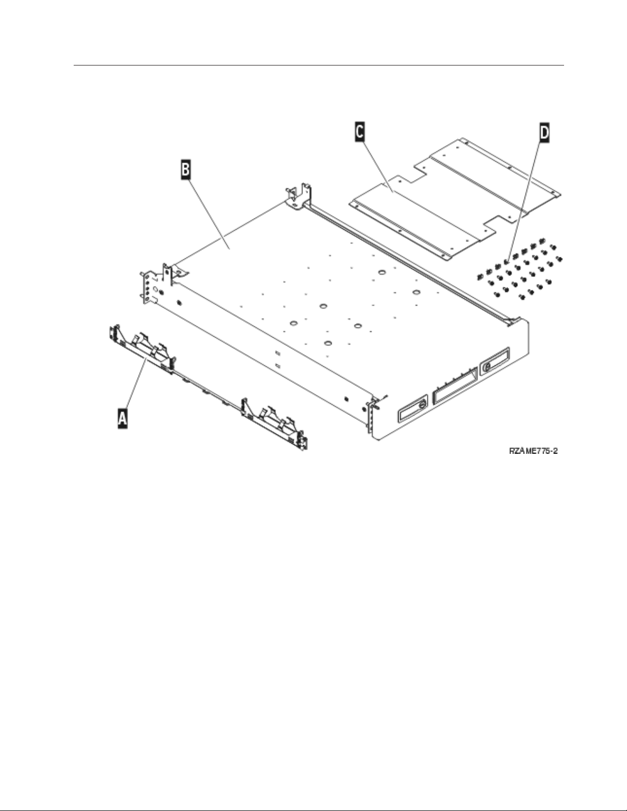
__ 1. Locate the cable management arm assembly A, rack shelf with rail assembly B, adapter plate
C, clips and screws D. Some extra screws are provided.
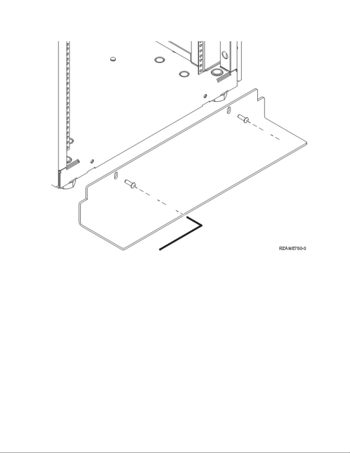
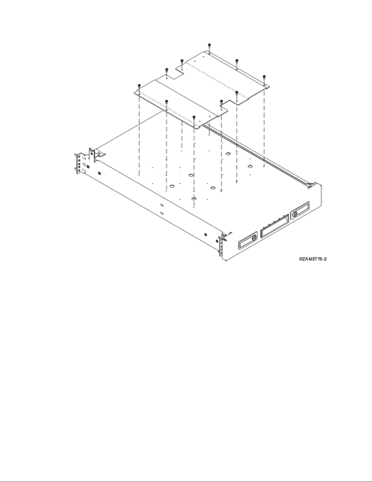
__ 2. Install the adapter plate on the shelf.
__ Locate the 10 screws to install the 825 adapter plate.
__ Install the plate as shown with the tool provided.
Install a Model 825 in a rack 7
Page 14
__ 3. Install four clips on the front of the rack.
If you are installing the system unit in the lower part of the rack, place the clips in EIA sections 1
and 2.
8 Model 825 In Rack Installation Instructions V5R3
Page 15
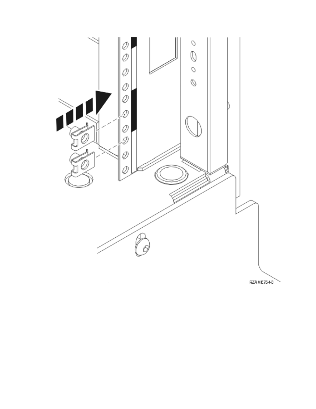
To install in the upper part, place the clips in EIA sections 17 and 18.
Install a Model 825 in a rack 9
Page 16

A Guidepins
B Clips
10 Model 825 In Rack Installation Instructions V5R3
Page 17
C Empty
4. Two people are needed to install the shelf and rail assembly. One is positioned in back and the
__
other one in the front of the rack.
__ 5. Lift the shelf and rail assembly into the rack from the front. You need to slant the shelf to fit
through the front opening.
__ 6. Align and insert the guidepins on the rail assembly with the correct holes in the back frame.
Install a Model 825 in a rack 11
Page 18

__ 7. Align and insert the guidepins on the rail assembly with the correct holes in the front frame.
__ 8. Install two screws on each side of the back frame to secure the shelf assembly.
__ 9. Open the latches A on the shelf. Slide the shelf partially out. Install the two screws on each side
of the front frame to secure the shelf assembly.
12 Model 825 In Rack Installation Instructions V5R3
Page 19
Note: If you have difficulty installing the screws, ensure the clips you previously installed are
still in the correct position.
__ 10. Slide the shelf into the rack.
__ 11. Press in the latches to lock shelf in the rack.
__ 12. Locate the cable management arm assembly.
__ 13. Push in the latches to secure the cable management arm to the back of the shelf A.
Install a Model 825 in a rack 13
Page 20

__ 14. Install two clips in the back frame B.
__ 15. Install the two screws where the clips are located to attach the other end of the cable management
arm to the back frame C.
__ 16. The rack shelf and rail assembly installation is complete.
__ 17. Continue with the instructions.
Remove devices before lifting the system unit into the rack
To safely lift your system unit onto the rack shelf, follow the instructions to remove devices from the
unit. Place devices that you remove in the electrostatic discharge bags that are provided to prevent
damage.
After removing the devices to get the system unit to an acceptable weight, three people are needed to
safely lift the system unit onto the rack shelf.
Continue with the following instructions.
14 Model 825 In Rack Installation Instructions V5R3
Page 21

Remove covers
Remove the front and side covers.
__ 1. Remove the front cover by gripping the sides of the cover and pulling the cover toward you A.
__ 2. Remove the side covers by loosening and removing the two thumbscrews and the two slotted
retainer screws on the back. Slide each of the covers from front to back until it stops.
Install a Model 825 in a rack 15
Page 22

__ 3. Pull the cover out.
16 Model 825 In Rack Installation Instructions V5R3
Page 23

Remove power supply
__ 1. Locate the power supply area at the back of the unit (P01 and P02).
__ 2. Pull the latch on the power supply handle.
__ 3. Lift up the handle on the power supply.
__ 4. Support the bottom of the supply as you slide it out of the unit.
Install a Model 825 in a rack 17
Page 24

__ 5. Repeat the steps to remove the other power supply.
Electrostatic discharge
Attach the disposable wrist strap to prevent electrostatic discharge from damaging a device. View
video. Attach the adhesive part of the foil to an unpainted surface on the frame of the unit.
Notes:
1. Follow the same precautions you would use without the wrist strap. The 2209 Disposable Wrist Strap
is for static control. It will not increase or decrease your risk of receiving electric shock when using or
working on electrical equipment.
2. Remove the liner from the copper foil at the end when you unroll the strap.
3. Attach the copper foil to an exposed, unpainted metal surface on the frame of the unit (electrical
ground).
4. Place devices that you remove in electrostatic discharge bags to prevent damage.
Remove disk units
__ 1. The disk units are located in the front of your system unit.
__ 2. It is very important to label the disk units and locations as you remove them so they are later
installed in the exact same position. For example, D01. Remove D01 first.
18 Model 825 In Rack Installation Instructions V5R3
Page 25

__ 3. Squeeze and pull the handle out toward you and down before you remove the disk unit. If the
handle is not all the way down, the disk unit will not slide out of the system.
__ 4. Support the bottom of the disk unit assembly as you slide it completely out of the system. Do not
hold the disk unit by the handle.
__ 5. Label the disk unit and put it in a static protective bag.
__ 6. Repeat the above steps for each disk unit in your system.
Install a Model 825 in a rack 19
Page 26

Remove fans
__ 1. Locate the fans in the front of your system unit (B01 and B02).
__ 2. Remove the fan assembly by pulling the latches.
20 Model 825 In Rack Installation Instructions V5R3
Page 27

__ 3. Repeat for each fan.
Install a Model 825 in a rack 21
Page 28

Remove tape, CD–ROM and DVD devices
__ 1. Locate the devices on the front of the system unit.
__ 2. Pull both handles on both sides of the device toward you.
__ 3. Slide the device out.
__ 4. Do not hold the device by the handles.
__ 5. Place the device in a static protective bag.
22 Model 825 In Rack Installation Instructions V5R3
Page 29

__ 6. Repeat the steps to remove each device.
Remove processor assembly
__ 1. Locate the processor assembly inside the side of the system unit.
__ 2. Remove the access cover A.
__ 3. Remove the processor card assemblies by doing the following:
Install a Model 825 in a rack 23
Page 30

__ a. Label the processor card assemblies and the location so they can be installed later in the
same location.
__ b. Unlatch the two latches until the card assembly slightly “pops” out.
__ c. Pull on both latches at the same time to remove the card assembly from the system unit.
__ d. Put the card assembly in a static protective bag.
4. Repeat the steps to remove all processor card assemblies.
__
Remove the network interface card
__ 1. Locate the network interface card on the top, back of the system unit.
__ 2. Make sure you have removed all processor assemblies before removing the network interface card.
__ 3. Remove any external cables from the card and note their locations.
__ 4. Remove the small cover on the top A. Pull the push-button out and slide the cover back to
remove.
24 Model 825 In Rack Installation Instructions V5R3
Page 31

__ 5. Unlatch the two latches until the card assembly slightly “pops” out B.
__ 6. Pull on both latches at the same time to remove the card assembly from the system unit C.
__ 7. Put the card assembly in a static protective bag.
Remove PCI cards
__ 1. Locate the PCI card positions inside the side of your system unit.
__ 2. Attention: Adapter cards are fragile:
v Handle only by the edges.
v Keep fingers off printed circuit area.
v Use static strap when handling.
3. Start at the top when removing the cards.
__
__ 4. Remove any cables from the cards and note their locations.
__ 5. As you remove the card, it is very important to write down the card number and position.
Record the card number in the correct position in the following table:
Position Card Number
C12
C11
C10
Install a Model 825 in a rack 25
Page 32

C09 HSL
C08 HSL
Imbed IOA
C06
C05
C04
C03
C02
C01
__ 6. Open the latch at the card position where you plan to remove the card. Move the latch
counterclockwise and then swing the latch out.
26 Model 825 In Rack Installation Instructions V5R3
Page 33

__ 7. Remove the card.
Install a Model 825 in a rack 27
Page 34

__ 8. Place the card in a static protective bag.
__ 9. Repeat the steps for each card.
Install unit in the rack
Use the following instructions to lift the system unit into the rack and attach it to the shelf.
__ 1. CAUTION:
When the unit is extended, its weight can turn over a rack that is not steady. Before you pull
the unit out of the rack, ensure that a rack stabilizer is attached to the bottom front of the rack.
Do not pull out more than one unit at a time. The rack can turn over if you pull out more than
one unit at a time. (RSFTC224)
__ 2. Install the side covers with lifting bars. Install the two thumbscrews and two slotted retainer
screws that originally were used to attach the system unit covers.
28 Model 825 In Rack Installation Instructions V5R3
Page 35

__ 3. CAUTION:
The weight of this part or unit is between 32 and 55 kilograms (70.5 and 121.2 pounds). It takes
three persons to safely lift this part or unit. (RSFTC205)
__ 4. Pull the rack shelf out until fully extended and locked in place.
__ 5. Locate, on the adapter plate that is attached to the shelf, the two holes where you will install
screws to securely attach the unit to the shelf.
Install a Model 825 in a rack 29
Page 36

__ 6. Lift the unit onto the shelf.
__ 7. Position the unit close to the front of edge of the shelf, approximately 2.5 centimeters.
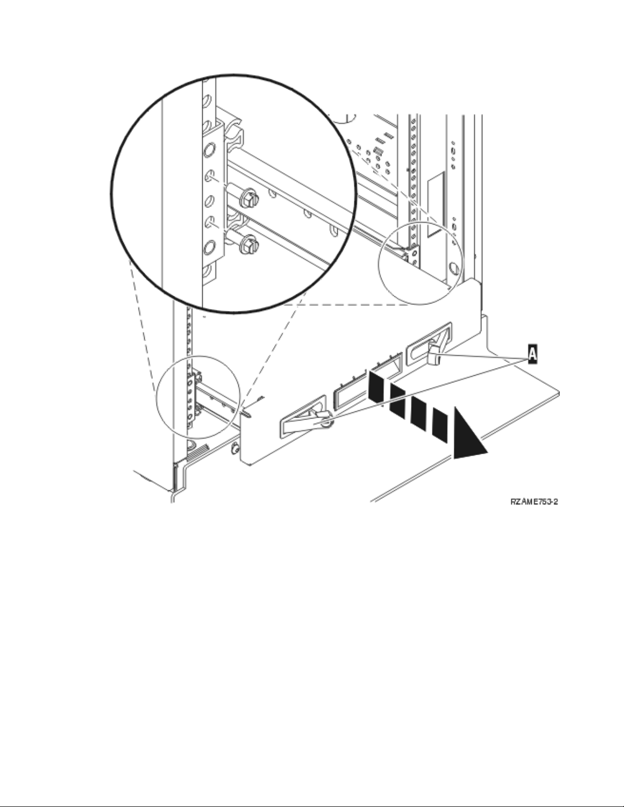
__ 8. Remove the side covers with lifting bars.
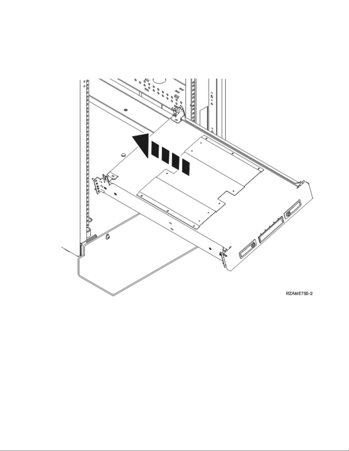
__ 9. Remove the air flow deflector.
30 Model 825 In Rack Installation Instructions V5R3
Page 37

__ 10. Move the bottom of the foam forward out of the way A .
Install a Model 825 in a rack 31
Page 38

__ 11. Install the two screws in the unit to secure the rack shelf. One screw location is in the back power
supply area B. The other screw location is in the front foam area C.
__ 12. Move the foam back in place.
__ 13. Install the air flow deflector.
__ 14. Continue with the instructions.
Install devices that were removed
Use the following instructions to install the devices that were removed.
Electrostatic discharge
Attach the disposable wrist strap to prevent electrostatic discharge from damaging a device. View
video. Attach the adhesive part of the foil to an unpainted surface on the frame of the unit.
Notes:
1. Follow the same precautions you would use without the wrist strap. The 2209 Disposable Wrist Strap
is for static control. It will not increase or decrease your risk of receiving electric shock when using or
working on electrical equipment.
2. Remove the liner from the copper foil at the end when you unroll the strap.
32 Model 825 In Rack Installation Instructions V5R3
Page 39

3. Attach the copper foil to an exposed, unpainted metal surface on the frame of the unit (electrical
ground).
Install disk units
__ 1. The disk units are located in the front of your system unit.
__ 2. Locate the disk drives and look at the label of the disk unit. It is very important to replace the
disk units in the same exact location where they were removed.
__ 3. Squeeze and pull the handle out toward you and down before you install the disk unit. If the
handle is not all the way down, the disk unit will not slide into the unit. View video.
Install a Model 825 in a rack 33
Page 40

__ 4. Do not hold the disk unit by the handle.
__ 5. Support the bottom of the disk unit assembly, slide the disk unit all the way in and lock it in place
by closing the latch.
__ 6. Repeat the above steps for each disk unit in your system.
__ 7. Install the disk unit covers.
__ 8. Continue with the instructions.
Install fans
__ 1. Locate the fan area on the front of the unit (B01 and B02).
__ 2. Install the fan assembly.
34 Model 825 In Rack Installation Instructions V5R3
Page 41

__ 3. Push in the latches.
Install tape, CD–ROM and DVD devices
__ 1. Install the device by sliding it forward and into the system unit. Yo u may need to remove the filler
blank above the control panel.
__ 2. Push the two latches that secure the device to the system unit frame until they stop.
Install a Model 825 in a rack 35
Page 42

__ 3. Repeat the steps for each removable media device.
Install network interface card
__ 1. Make sure you install the network interface card before the processor assemblies.
__ 2. Install any external cables from the card.
__ 3. Slide the card assembly into the system unit A.
36 Model 825 In Rack Installation Instructions V5R3
Page 43

__ 4. Push on both card latches at the same time.
__ 5. Close the latches when you cannot push the card assembly any further into the system unit B.
__ 6. Install the small cover on the top C.
__ 7. Push in the push-button.
Install processor assembly
__ 1. Install the processor card assemblies by doing the following:
__ a. Install the processor card assemblies in the correct location.
__ b. Slide the card assembly into the system unit using the guiderails.
__ c. Pull on both latches at the same time.
__ d. Close the latches when you cannot push the card assembly any further into the system unit.
Install a Model 825 in a rack 37
Page 44

__ 2. Install the access cover A.
__ 3. Repeat the steps to install all processor card assemblies.
38 Model 825 In Rack Installation Instructions V5R3
Page 45

Install PCI cards
__ 1. Locate the adapter card positions inside your system unit.
__ 2. It is very important to install the card back into the same position it was removed. Use the
information you recorded earlier in step 5 on page 25.
__ 3. Make sure the card latch is open at the card position where you plan to install the card. Move the
latch counterclockwise and then swing the latch out.
Install a Model 825 in a rack 39
Page 46

40 Model 825 In Rack Installation Instructions V5R3
Page 47

__ 4. Attention: Adapter cards are fragile:
v Handle only by the edges.
v Keep fingers off printed circuit area.
v Use static strap when handling.
v Leave in protective packaging until ready to install.
__ 5. Start at the bottom when installing the cards.
__ 6. Align the card with the card holders inside the system unit and push until it is connected securely.
__ 7. Swing the latch in and move the latch clockwise to secure the card.
__ 8. Connect any cables you removed.
__ 9. Repeat the above steps for each card.
Install covers
Install the front and side covers.
__ 1. Install the side covers.
Install a Model 825 in a rack 41
Page 48

__ a. Install the thumbscrews on the back, left side cover (view from front).
__ b. Install the slotted retainer screws on the back, right side cover (view from front). Slide the
shelf partially in to have space to tighten the screws with the tool provided.
2. Install the front cover.
__
__ 3. Push in the spring latches on the extended shelf rails and slide the shelf in.
42 Model 825 In Rack Installation Instructions V5R3
Page 49

__ 4. Close the latches.
__ 5. Replace filler panels in empty spaces.
__ 6. Install the black cover strips over the holes on each side of the unit.
Install a Model 825 in a rack 43
Page 50

44 Model 825 In Rack Installation Instructions V5R3
Page 51

__ 7. Install the rack trim on the sides and top that you removed when unpacking the rack.
Install power supply
You will install the following devices:
__ 1. Locate the power supply area at the back of the unit.
__ 2. Lift up the handle on the power supply.
View video.
__ 3. Slide the power supply into the system unit.
__ 4. Move the handle down to lock in place.
__ 5. Push in the latch.
Completing the rack installation
Locate the Start Here instructions that came with your unit to finish the set up of your unit. Yo u may
have already completed some of the steps.
If you installed an existing system unit:
__ 1. Plug in the power cord for the system unit.
__ 2. Plug in any power cords, such as printers and displays.
__ 3. Power on the system unit and any devices connected to the system unit.
Install a Model 825 in a rack 45
Page 52

46 Model 825 In Rack Installation Instructions V5R3
Page 53

Appendix. Notices
This information was developed for products and services offered in the U.S.A.
IBM may not offer the products, services, or features discussed in this document in other countries.
Consult your local IBM representative for information on the products and services currently available in
your area. Any reference to an IBM product, program, or service is not intended to state or imply that
only that IBM product, program, or service may be used. Any functionally equivalent product, program,
or service that does not infringe any IBM intellectual property right may be used instead. However, it is
the user’s responsibility to evaluate and verify the operation of any non-IBM product, program, or
service.
IBM may have patents or pending patent applications covering subject matter described in this
document. The furnishing of this document does not give you any license to these patents. You can send
license inquiries, in writing, to:
IBM Director of Licensing
IBM Corporation
North Castle Drive
Armonk, NY 10504-1785
U.S.A.
following paragraph does not apply to the United Kingdom or any other country where such
The
provisions are inconsistent with local law: INTERNATIONAL BUSINESS MACHINES CORPORATION
PROVIDES THIS PUBLICATION “AS IS” WITHOUT WARRANTY OF ANY KIND, EITHER EXPRESS
OR IMPLIED, INCLUDING, BUT NOT LIMITED TO, THE IMPLIED WARRANTIES OF
NON-INFRINGEMENT, MERCHANTABILITY OR FITNESS FOR A PARTICULAR PURPOSE. Some
states do not allow disclaimer of express or implied warranties in certain transactions, therefore, this
statement may not apply to you.
This information could include technical inaccuracies or typographical errors. Changes are periodically
made to the information herein; these changes will be incorporated in new editions of the publication.
IBM may make improvements and/or changes in the product(s) and/or the program(s) described in this
publication at any time without notice.
Any references in this information to non-IBM We b sites are provided for convenience only and do not in
any manner serve as an endorsement of those Web sites. The materials at those Web sites are not part of
the materials for this IBM product and use of those Web sites is at your own risk.
IBM may use or distribute any of the information you supply in any way it believes appropriate without
incurring any obligation to you.
Any performance data contained herein was determined in a controlled environment. Therefore, the
results obtained in other operating environments may vary significantly. Some measurements may have
been made on development-level systems and there is no guarantee that these measurements will be the
same on generally available systems. Furthermore, some measurements may have been estimated through
extrapolation. Actual results may vary. Users of this document should verify the applicable data for their
specific environment.
Information concerning non-IBM products was obtained from the suppliers of those products, their
published announcements or other publicly available sources. IBM has not tested those products and
cannot confirm the accuracy of performance, compatibility or any other claims related to non-IBM
products. Questions on the capabilities of non-IBM products should be addressed to the suppliers of
those products.
© Copyright IBM Corp. 2004, 2005 47
Page 54

All statements regarding IBM’s future direction or intent are subject to change or withdrawal without
notice, and represent goals and objectives only.
All IBM prices shown are IBM’s suggested retail prices, are current and are subject to change without
notice. Dealer prices may vary.
This information is for planning purposes only. The information herein is subject to change before the
products described become available.
This information contains examples of data and reports used in daily business operations. To illustrate
them as completely as possible, the examples include the names of individuals, companies, brands, and
products. All of these names are fictitious and any similarity to the names and addresses used by an
actual business enterprise is entirely coincidental.
If you are viewing this information softcopy, the photographs and color illustrations may not appear.
The drawings and specifications contained herein shall not be reproduced in whole or in part without the
written permission of IBM.
IBM has prepared this publication for use by hardware service representatives in the maintenance or
repair of the specific machines indicated. IBM makes no representations that it is suitable for any other
purpose.
The drawings and specifications contained herein shall not be reproduced in whole or in part without the
written permission of IBM.
IBM has prepared this publication for use by customer personnel for operating and planning for the
specific machines indicated. IBM makes no representations that it is suitable for any other purpose.
Trademarks
The following terms are trademarks of International Business Machines Corporation in the United States,
other countries, or both:
Application System/400
AS/400
e (logo)
IBM
iSeries
Operating System/400
OS/400
400
Lotus, Freelance, and WordPro are trademarks of International Business Machines Corporation and Lotus
Development Corporation in the United States, other countries, or both.
C-bus is a trademark of Corollary, Inc. in the United States, other countries, or both.
ActionMedia, LANDesk, MMX, Pentium, and ProShare are trademarks or registered trademarks of Intel
Corporation in the United States, other countries, or both.
Microsoft, Windows, Windows NT, and the Windows logo are trademarks of Microsoft Corporation in the
United States, other countries, or both.
SET and the SET Logo are trademarks owned by SET Secure Electronic Transaction LLC.
48 Model 825 In Rack Installation Instructions V5R3
Page 55

Java and all Java-based trademarks are trademarks of Sun Microsystems, Inc. in the United States, other
countries, or both.
UNIX is a registered trademark of The Open Group in the United States and other countries.
Other company, product or service names may be trademarks or service marks of others.
Terms and conditions for downloading and printing publications
Permissions for the use of the publications you have selected for download are granted subject to the
following terms and conditions and your indication of acceptance thereof.
Personal Use: You may reproduce these Publications for your personal, noncommercial use provided that
all proprietary notices are preserved. You may not distribute, display or make derivative works of these
Publications, or any portion thereof, without the express consent of IBM.
Commercial Use: You may reproduce, distribute and display these Publications solely within your
enterprise provided that all proprietary notices are preserved. You may not make derivative works of
these Publications, or reproduce, distribute or display these Publications or any portion thereof outside
your enterprise, without the express consent of IBM.
Except as expressly granted in this permission, no other permissions, licenses or rights are granted, either
express or implied, to the Publications or any information, data, software or other intellectual property
contained therein.
IBM reserves the right to withdraw the permissions granted herein whenever, in its discretion, the use of
the Publications is detrimental to its interest or, as determined by IBM, the above instructions are not
being properly followed.
You may not download, export or re-export this information except in full compliance with all applicable
laws and regulations, including all United States export laws and regulations. IBM MAKES NO
GUARANTEE ABOUT THE CONTENT OF THESE PUBLICATIONS. THE PUBLICATIONS ARE
PROVIDED ″AS-IS″ AND WITHOUT WARRANTY OF ANY KIND, EITHER EXPRESSED OR IMPLIED,
INCLUDING BUT NOT LIMITED TO IMPLIED WARRANTIES OF MERCHANTABILITY AND FITNESS
FOR A PARTICULAR PURPOSE
All material copyrighted by IBM Corporation.
By downloading or printing a publication from this site, you have indicated your agreement with these
terms and conditions.
Code disclaimer information
This document contains programming examples.
IBM grants you a nonexclusive copyright license to use all programming code examples from which you
can generate similar function tailored to your own specific needs.
All sample code is provided by IBM for illustrative purposes only. These examples have not been
thoroughly tested under all conditions. IBM, therefore, cannot guarantee or imply reliability, serviceability,
or function of these programs.
All programs contained herein are provided to you ″AS IS″ without any warranties of any kind. The
implied warranties of non-infringement, merchantability and fitness for a particular purpose are expressly
disclaimed.
Appendix. Notices 49
Page 56

Electronic Emission Notices
Federal Communications Commission (FCC) statement
Note: This equipment has been tested and found to comply with the limits for a Class A digital device,
pursuant to Part 15 of the FCC Rules. These limits are designed to provide reasonable protection against
harmful interference when the equipment is operated in a commercial environment. This equipment
generates, uses, and can radiate radio frequency energy and, if not installed and used in accordance with
the instruction manual, may cause harmful interference to radio communications. Operation of this
equipment in a residential area is likely to cause harmful interference, in which case the user will be
required to correct the interference at his own expense.
Properly shielded and grounded cables and connectors must be used in order to meet FCC emission
limits. IBM is not responsible for any radio or television interference caused by using other than
recommended cables and connectors or by unauthorized changes or modifications to this equipment.
Unauthorized changes or modifications could void the user’s authority to operate the equipment.
This device complies with Part 15 of the FCC rules. Operation is subject to the following two conditions:
(1) this device may not cause harmful interference, and (2) this device must accept any interference
received, including interference that may cause undesired operation.
Responsible Party:
International Business Machines Corporation
New Orchard Road
Armonk, NY 10504
Telephone: 1-919-543-2193
Industry Canada Compliance Statement
This Class A digital apparatus meets the requirements of the Canadian Interference-Causing Equipment
Regulations.
Avis de conformité à la réglementation d’Industrie Canada
Cet appareil numérique de la classe A respecte toutes les exigences du Règlement sur le matériel
brouilleur du Canada.
European Community Compliance Statement
This product is in conformity with the protection requirements of EU Council Directive 89/336/EEC on
the approximation of the laws of the Member States relating to electromagnetic compatibility. IBM cannot
accept responsibility for any failure to satisfy the protection requirements resulting from a
non-recommended modification of the product, including the fitting of non-IBM option cards.
Australia and New Zealand Class A statement
Attention: This is a Class A product. In a domestic environment this product may cause radio
interference in which case the user may be required to take adequate measures.
VCCI Statement - Japan
50 Model 825 In Rack Installation Instructions V5R3
Page 57

The following is a summary of the VCCI Japanese statement in the box above.
This is a Class A product based on the standard of the Voluntary Control Council for Interference by
Information Technology Equipment (VCCI). If this equipment is used in a domestic environment, radio
disturbance may arise. When such trouble occurs, the user may be required to take corrective actions.
Electromagnetic Interference (EMI) Statement - People’s Republic of China
Per GB 9254–1998, the user manual for a Class A product must carry the following warning message
(English translation from the Chinese standard) about use in a residential environment in Chinese
(Simplified Chinese):
Declaration: This is a Class A product. In a domestic environment this product may cause radio
interference in which case the user may need to perform practical action.
Electromagnetic Interference (EMI) Statement - Taiwan
The following is a summary of the EMI Taiwan statement above.
Warning: This is a Class A product. In a domestic environment this product may cause radio interference
in which case the user will be required to take adequate measures.
Radio Protection for Germany
Dieses Gerät ist berechtigt in Übereinstimmung mit Dem deutschen EMVG vom 9.Nov.92 das
EG–Konformitätszeichen zu führen.
Der Aussteller der Konformitätserklärung ist die IBM Germany.
Dieses Gerät erfüllt die Bedingungen der EN 55022 Klasse A. Für diese von Geräten gilt folgende
Bestimmung nach dem EMVG:
Appendix. Notices 51
Page 58

Geräte dürfen an Orten, für die sie nicht ausreichend entstört sind, nur mit besonderer Genehmigung des
Bundesministers für Post und Telekommunikation oder des Bundesamtes für Post und
Telekommunikation betrieben werden. Die Genehmigung wird erteilt, wenn keine elektromagnetischen
Störungen zu erwarten sind.
(Auszug aus dem EMVG vom 9.Nov.92, Para.3, Abs.4)
Hinweis
Dieses Genehmigungsverfahren ist von der Deutschen Bundespost noch nicht veröffentlicht worden.
Electronic Emission Notices
The following Statement applies to this IBM product. The statement for other IBM products intended for
use with this product will appear in their accompanying manuals.
Federal Communications Commission (FCC) statement
Note: This equipment has been tested and found to comply with the limits for a class B digital device,
pursuant to Part 15 of the FCC Rules. These limits are designed to provide reasonable protection against
harmful interference in a residential installation. This equipment generates, uses, and can radiate radio
frequency energy and, if not installed and used in accordance with the instructions, may cause harmful
interference to radio communications. However, there is no guarantee that interference will not occur in a
particular installation. If this equipment does cause harmful interference to radio or television reception,
which can be determined by turning the equipment off and on, the user is encouraged to try to correct
the interference by one or more of the following measures:
v Reorient or relocate the receiving antenna.
v Increase the separation between the equipment and receiver.
v Connect the equipment into an outlet on a circuit different from that to which the receiver is
connected.
v Consult an IBM authorized dealer or service representative for help.
Properly
shielded and grounded cables and connectors must be used in order to meet FCC emission
limits. Proper cables and connectors are available from IBM authorized dealers. IBM is not responsible for
any radio or television interference caused by using other than recommended cables or connectors or by
unauthorized changes or modifications to this equipment. Unauthorized changes or modifications could
void the user’s authority to operate the equipment.
This device complies with Part 15 of the FCC Rules. Operation is subject to the following two conditions:
(1) this device may not cause harmful interferences, and (2) this device must accept any interferences
received, including interference that may cause undesired operation.
Responsible Party:
International Business Machines Corporation
New Orchard Road
Armonk, NY 10504
Telephone: 1-919-543-2193
Industry Canada Compliance Statement
This Class B digital apparatus meets the requirements of the Canadian Interference-Causing Equipment
Regulations.
52 Model 825 In Rack Installation Instructions V5R3
Page 59

Avis de conformité à la réglementation d’Industrie Canada
Cet appareil numérique de la classe B respecte toutes les exigences du Réglement sur le matériel
brouilleur du Canada.
European Community Compliance Statement
This product is in conformity with the protection requirements of EC Council Directive 89/336/EEC on
the approximation of the laws of the Member States relating to electromagnetic compatibility. IBM cannot
accept responsibility for any failure to satisfy the protection requirements resulting from a
non-recommended modification of the product, including the fitting of non-IBM option cards.
This product has been tested and found to comply with the limits for Class B Information Technology
Equipment according to CISPR 22 / European Standard EN 55022. The limits for Class B equipment were
derived for typical residential environments to provide reasonable protection against interference with
licensed communication devices.
Properly shielded and grounded cables and connectors (IBM part number 75G5958 or its equivalent)
must be used in order to reduce the potential for causing interference to radio and TV communications
and to other electrical or electronic equipment. Such cables and connectors are available from IBM
authorized dealers. IBM cannot accept responsibility for an interference caused by using other than
recommended cables and connectors.
Appendix. Notices 53
Page 60

54 Model 825 In Rack Installation Instructions V5R3
Page 61

Page 62

Printed in USA
 Loading...