

Page 1

Install the server in
®
xSeries 250
Installation Guide
the rack, if required
Install options:
• Drives
• Microprocessors
• Adapters
• Power supplies
• Memory
Cable the server
and options
Welcome. . .
Thank you for buying an
IBM xSeries server.
Start the server
This server
Installation Guide
contains information for setting
up and configuring your server.
For detailed information
about your server, view the
User's Reference
on the
Documentation CD.
You can also find the most
current information about your
server on the IBM Web site at:
http://www.ibm.com/pc/support
Did the server
start correctly?
Yes
Use ServerGuide™
to set up and
configure hardware
Did configuration
complete?
Yes
Use
ServerGuide to
install operating
system?
Yes
Use ServerGuide to
install applications,
such as IBM systems
management software
and IBM ServeRAID
programs
No
No
No
Go to the Server Support
flow chart
Go to the Web for instructions,
http://www.ibm.com/pc/support
System is ready to use.
Go to the Server Support
flow chart to register
and profile your server.
Page 2

Server Support
Server working
properly?
Yes
No
Check all cables for loose connections
and verify that all optional devices you
installed are on the ServerProven list.
You can view the ServerProven list at:
http://www.ibm.com/pc/compat
Problem
solved?
®
Yes
No
Use the troubleshooting
information provided with
your server to determine
the cause of the problem
and the action to take.
Register and profile your server
After you register and profile, you will be able to:
• Diagnose problems using the IBM Online Assistant
• Participate in the IBM discussion forum
• Receive e-mail notifications of technical updates
related to your profiled products
Register at:
Profile at:
http://www.ibm.com/pc/register
http://www.ibm.com/pc/support
You can view a list of
IBM HelpCenter phone numbers at:
http://www.ibm.com/pc/support
®
Problem
solved?
Yes
No
Flash the latest levels of BIOS,
service processor, diagnostics,
and RAID code.
You can download this code at:
http://www.ibm.com/pc/support
Yes
Problem
solved?
No
Phone an
IBM HelpCenter
Page 3

IBM
IBM® xSeries 250
Installation Guide
SC21-P901-90
Page 4

NOTE
Before using this information and the product it supports, be sure to read the general information in
“Appendix A. Product warranties and notices,” on page 55.
First Edition (March 2001) 1.0
© Copyright International Business Machines Corporation 2001. All rights reserved.
US Government Users Restricted Rights – Use, duplication or disclosure restricted by GSA ADP Sch edu le Cont ra ct wit h
IBM Corp.
Page 5

© Copyright IBM Corp. 2001 iii
Contents
Safety . . . . . . . . . . . . . . . . . . . . . . . . . . . . . v
Chapter 1.Introduction . . . . . . . . . . . . . . . . 1
Features and specifications . . . . . . . . . . . . . . . . . . . . . . . . 2
Notices used in this book. . . . . . . . . . . . . . . . . . . . . . . . . . 3
Major components of the xSeries 250 server. . . . . . . . . . 4
Chapter 2.Installing options . . . . . . . . . . . 7
Before you begin . . . . . . . . . . . . . . . . . . . . . . . . . . . . . . . . . 7
System reliability considerations. . . . . . . . . . . . . . . . . 7
Working inside the server with the power on . . . . . . 8
Handling static-sensitive devices . . . . . . . . . . . . . . . . 8
Removing the server top cover and bezel. . . . . . . . . . . . 9
Removing the top cover . . . . . . . . . . . . . . . . . . . . . . . . 9
Removing the media-bay bezel . . . . . . . . . . . . . . . . . 10
Installing adapters. . . . . . . . . . . . . . . . . . . . . . . . . . . . . . . 11
Installing a hot-plug PCI adapter (slots 3 through 6) 12
Installing a non-hot-plug PCI adapter (slots 1 and 2) .
14
Cabling example for the ServeRAID adapter . . . . . 16
Installing memory options. . . . . . . . . . . . . . . . . . . . . . . . 22
Using the LVD SCSI backplane. . . . . . . . . . . . . . . . . . . . 24
Installing a SCSI repeater card. . . . . . . . . . . . . . . . . . 25
Installing a drive in a hot-swap bay. . . . . . . . . . . . . . . . 31
Installing a microprocessor . . . . . . . . . . . . . . . . . . . . . . . 33
Installing a hot-swap power supply. . . . . . . . . . . . . . . . 34
Completing the installation . . . . . . . . . . . . . . . . . . . . . . . 36
Installing the media-bay bezel. . . . . . . . . . . . . . . . . . 36
Installing the top cover . . . . . . . . . . . . . . . . . . . . . . . . 37
Reconfiguring the server. . . . . . . . . . . . . . . . . . . . . . . 37
Cabling the server . . . . . . . . . . . . . . . . . . . . . . . . . . . . . . 38
Chapter 3.Server power, controls, and
indicators . . . . . . . . . . . . . . . . . . . . . . . . . 39
Turning on the server . . . . . . . . . . . . . . . . . . . . . . . . . . . . 39
Turning off the server . . . . . . . . . . . . . . . . . . . . . . . . . . . . 40
Server controls and indicators. . . . . . . . . . . . . . . . . . . . . 41
Information LED panel. . . . . . . . . . . . . . . . . . . . . . . . . . . 43
Chapter 4.Configuring your server . . . . . 45
Using the ServerGuide CDs. . . . . . . . . . . . . . . . . . . . . . . 45
Chapter 5.Solving problems. . . . . . . . . . . 47
POST beep code descriptions. . . . . . . . . . . . . . . . . . . . . . 47
POST error messages. . . . . . . . . . . . . . . . . . . . . . . . . . . . . 48
ServerGuide startup problems . . . . . . . . . . . . . . . . . . . . 50
Troubleshooting chart. . . . . . . . . . . . . . . . . . . . . . . . . . . . 51
Appendix A. Product warranties and
notices . . . . . . . . . . . . . . . . . . . . . . . . . . . 55
Warranty Statement. . . . . . . . . . . . . . . . . . . . . . . . . . . . . . 55
Warranty Period . . . . . . . . . . . . . . . . . . . . . . . . . . . . . . 55
IBM Statement of Limited Warranty. . . . . . . . . . . . . 55
Part 1 - General Terms . . . . . . . . . . . . . . . . . . . . . . 55
Part 2 - Country-unique Terms. . . . . . . . . . . . . . . 57
Notices. . . . . . . . . . . . . . . . . . . . . . . . . . . . . . . . . . . . . . . . . 63
Edition notice . . . . . . . . . . . . . . . . . . . . . . . . . . . . . . . . 63
Processing date data . . . . . . . . . . . . . . . . . . . . . . . . . . 64
Trademarks . . . . . . . . . . . . . . . . . . . . . . . . . . . . . . . . . . 64
Important notes . . . . . . . . . . . . . . . . . . . . . . . . . . . . . . 64
Electronic emission notices . . . . . . . . . . . . . . . . . . . . . . . 65
Federal Communications Commission (FCC)
Statement. . . . . . . . . . . . . . . . . . . . . . . . . . . . . . . . . . . . 65
Industry Canada Class A emission compliance
statement . . . . . . . . . . . . . . . . . . . . . . . . . . . . . . . . . . . . 65
Australia and New Zealand Class A statement. . . . 65
United Kingdom telecommunications safety
requirement. . . . . . . . . . . . . . . . . . . . . . . . . . . . . . . . . . 66
European Union EMC Directive conformance
statement . . . . . . . . . . . . . . . . . . . . . . . . . . . . . . . . . . . . 66
Taiwan electrical emission statement . . . . . . . . . . . . 66
Japanese Voluntary Control Council for Interference
(VCCI) statement . . . . . . . . . . . . . . . . . . . . . . . . . . . . . 66
Power cords . . . . . . . . . . . . . . . . . . . . . . . . . . . . . . . . . . . . 67
Index . . . . . . . . . . . . . . . . . . . . . . . . . . . . . . 69
Page 6

iv IBM® xSeries 250: Installation Guide
Page 7

© Copyright IBM Corp. 2001 v
Safety
Before installing this product, read the Safety Information book .
Antes de instalar este produto, leia o Manual de Informações sobre Segurança.
Læs hæftet med sikkerhedsforskrifter, før du installerer dette produkt.
Lue Safety Information -kirjanen, ennen kuin asennat tämän tuotteen.
Avant de procéder à l'installation de ce produit, lisez le manu el Safety Information.
Vor Beginn der Installation die Broschüre mit Sicherheitshinweisen lesen.
Prima di installare questo prodotto, leggere l'opuscolo contenente le informazioni
sulla sicurezza.
Pred instalací tohoto produktu si prectete prírucku bezpecnostních instrukcí.
Przed zainstalowaniem tego produktu należy przeczytać broszurę Informacje Dotyczące
Bezpieczeństwa.
Page 8

vi IBM® xSeries 250: Installation Guide
Lees voordat u dit product installeert eerst het boekje met veiligheidsvoorschriften.
Les heftet om sikkerhetsinformasjon (Safety Information) før du installerer dette
produktet.
Antes de instalar este produto, leia o folheto Informações sobre Segurança.
Antes de instalar este producto, lea la Información de Seguridad.
Läs säkerhetsinformationen innan du installerar den här produkten.
Перед установкой продукта прочтите брошюру по технике безопасности
(Safety Information).
Pred inštaláciou tohto produktu si pre ítajte Informa nú brožúrku o bezpe nosti.
Preden namestite ta izdelek, preberite knjižico Varnostne informacije.
Installálás el tt olvassa el a Biztonsági el írások kézikönyvét !
Page 9

vii
Statement 1
Danger
Electrical current from power, telephone, and communication cables is hazardous.
To avoid a shock hazard:
• Do not connect or disconnect any cables or perform installation, maintenance, or
reconfiguration of this product during an electrical storm.
• Connect all power cords to a properly wired and grounded electrical outlet.
• Connect to properly wired outlets any equipme nt that will be atta ched to this product.
• When possible, use one hand only to connect or disconnect signal cables.
• Never turn on any equipment when there is evidence of fire, water, or structural
damage.
• Disconnect the attached power cords, telecommunications systems, networks, and
modems before you open the device covers, unless instructed otherwise in the
installation and configuration procedures.
• Connect and disconnect cables as described in the following table when installing,
moving, or opening covers on this product or attached devices.
To connect:
1. Turn everything OFF.
2. First, attach all cables to devices.
3. Attach signal cables to connectors.
4. Attach power cords to outlet.
5. Turn device ON.
To disconnect:
1. Turn everything OFF.
2. First, remove power cords from o utle t.
3. Remove signal cables from connectors.
4. Remove all cables from devices.
Page 10

viii IBM® xSeries 250: Installation Guide
Statement 2
CAUTION:
When replacing the lithium battery, use only IBM Part N umber 33F8 354 or an equ ivalen t
type battery recommended by the manufacturer. If your system has a module co nta ining
a lithium battery, replace it only with the same module type made by the same
manufacturer. The battery contains lithium and can explode if not properly used,
handled, or disposed of.
Do not:
• Throw or immerse into water.
• Heat to more than 100 C (212 F)
• Repair or disassemble
Dispose of the battery as required by local ordinances or regulations.
Statement 3
CAUTION:
When laser products (such as CD-ROMs, DVD drives, fiber optic devices, or transmitters)
are installed, note the following:
• Do not remove the covers. Removing the covers of the laser product could result in
exposure to hazardous laser radiation. There are no serviceable parts inside the device.
• Use of controls or adjustments or performance of proc edures other than tho se specified
herein might result in hazardous radiation exposure.
Danger
Some laser products contain an embedded Class 3A or Class 3B laser diode. Note the
following. Laser radiation when open. Do not stare into the beam, do not view directly with
optical instruments, and avoid direct exposure to the beam.
Page 11

ix
Statement 4
≥18 kg (39.7 lbs) ≥32 kg (70.5 lbs) ≥55 kg (121.2 lbs)
CAUTION:
Use safe practices when lifting.
Statement 5
CAUTION:
The power control button on the devic e and the pow er switch on the p ower supply do not
turn off the electrical current supplied to the device. The device also might have more
than one power cord. To remove all electrical current from the device, ensure that all
power cords are disconnected from the power source.
1
2
3
Page 12

x IBM® xSeries 250: Installation Guide
Page 13

© Copyright IBM Corp. 2001 1
Chapter 1. Introduction
Thank you for purchasing an IBM® xSeries 250 server. This Installation Guide
provides the information that you need to:
• Set up and cable your server
• Start and configure your server
• Install your network operating system (NOS)
Packaged with this Installation Guide are software CDs that help you configure
hardware, install device drivers, and install the network operating sys tem (NOS).
Also included is an IBM xSeries Documentation CD that provides detailed information
about this server.
Your server comes with a three-year limited warranty and IBM Server Start Up
Support. If you have access to the World Wide Web, you can obtain up-to-date
information about your server model and other IBM server products at the following
World Wide Web address:
http://www.ibm.com/pc/us/eserver/xseries
Refer to the Rack Installation Instructions for complete details on rack installation
instructions.
Record your product information in this table.
Product name _________________________________________
Machine type _________________________________________
Model number _________________________________________
Serial number _________________________________________
Page 14

2 IBM® xSeries 250: Installation Guide
Features and specifications
The following table provides a summary of the fea tures and specifications for your
xSeries 250 server.
Microprocessor:
• Intel® Pentium® III Xeon™
• 32 KB of level-1 cache
• 1 MB of level-2 cache (minimum)
• Expandable to four
microprocessors
Memory:
• Maximum: 16 GB
• Type: ECC, SDRAM, Registered
DIMMs
• Slots: 4-way interleaved, 16 slots
Drives standard:
• Diskette: 1.44 MB
• CD-ROM: IDE
Expansion bays:
• Hot-swap: 10 slim-high
• Non-hot-swap: Two 5.25-inch
LVD SCSI Bac kplane:
• Ultra160 capab le
• Two SCSI channels, each with
five connectors, in a split
configuration
• Supports a maximum of 10 slimhigh hard disk drives
PCI expansion slots:
• Four 33 MHz 64-bit hot-plug
• Two 66 MHz 64-bit non-hot-plug
Hot-swap power supplies:
250 Watt (115-230 V ac)
• Minimum: Two
• Maximum: Four
• Three for redundancy
Redundant cooling:
• Four hot-swap fan assemblies
Video:
• S3 video controller
• Compatible with S V G A a nd VGA
• 4 MB video memory
Size:
• Height: 356 mm (14 in.)
• Depth: 650 mm (25. 6 in.)
• Width: 440 mm (17.3 in.)
• Weight: 34.4 kg (76 lb.) to 61 kg
(134 lb.) depending upon
configuration
Integrated functions:
• Advanced System Management
processor
• Dual Ultra2 (LVD) SCSI
controller, one external port, one
internal port
• One 10BASE-T/100BASE-TX
AMD Ethernet controller
• Two serial ports
• One parallel port
• Two Universal Serial Bus ports
• Keyboard port
• Mouse port
• Video port
• One management port
• Two Advanc ed Sy s t e m
Management Interconnect ports
Acoustical noise emissions:
• Sound power, idle: 6.3 bel
maximum
• Sound power, operating: 6.3 bel
maximum
• Sound pressure, idle: 49 dBa
maximum
• Sound pressure, operating: 49
dBa maximum
Environment:
• Air temperature:
— Server on: 10º to 35º C (50º to
95º F). Altitude: 0 to 914 m
(3000 ft.)
— Server on: 10º to 32º C (50º to
89.6º F). Altitude: 914 m
(3000 ft.) to 2133 m (7000 ft.)
— Server off: 10º to 43º C (50º to
110º F). Maximum altitude:
2133 m (7000 ft.)
• Humidity:
— Server on: 8% to 80%
— Server off: 8% to 80%
Heat output:
Approximate heat output in British
Thermal Units (BTU) per hour
• Minimum configuration: 1023.9
BTU
• Maximum configuration: 2764. 6
BTU
Electrical input:
• Sine-wave input (50-60 Hz)
required
• Input voltage low range:
— Minimum: 90 V ac
— Maximum: 137 V ac
• Input voltage high range:
— Minimum: 180 V ac
— Maximum: 265 V ac
• Input kilovolt-amperes (kVA)
approximately:
— Minimum: 0.08 kVA
— Maximum: 0. 52 kVA
Table 1. Features and specifications.
Page 15

Chapter 1. Introducti on 3
Notices used in this book
The caution and danger notices also appear in the multilingual Safety Information book
provided on the IBM xSeries Documentat io n CD that comes with your xSeries product.
Each notice is numbered for easy reference to the corresponding notices in the safety
book.
The following types of notices are used in this book:
• Note: These notices provide important tips, guidance, or advice.
• Important: These notices provide information or advice that might help you
avoid inconvenient or problem situations.
• Attention: These notices indicate possible damage to programs, devices, or data.
An attention notice is placed just before the instruction or situation in which
damage could occur.
• Caution: These notices indicate situations that can be potentially hazardous to
you. A caution notice is placed just before the description of a potentia lly
hazardous procedure step or situation.
• Danger: These notices indicate situations that can be potentially lethal or
extremely hazardous to you. A danger notice is placed just before the description
of a potentially lethal or extremely hazardous procedure step or situation.
Page 16

4 IBM® xSeries 250: Installation Guide
Major components of the xSeries 250 server
The orange color on components and labels in your server identifies hot-swap or hotplug components. This means that you can install or remove the components while
the system is running, provided that your system is configured to support this
function. For complete information about installing or removing a hot-swap or hotplug component, see the information provided in the procedures in this document.
The blue color on components and labels indicates touch points where a component
can be gripped, a latch moved, and so on.
Power supply
Fan assembly #1Filler Panel
Removable-media
drive
Hot-swap
drive
Power backplane
SCSI backplane
Shuttle
Media-bay bezel
Page 17

Chapter 1. Introducti on 5
Microprocessor
Terminator card
Memory
module
Shuttle
I/O board
Memory board
Shuttle
cover
VRM
Fan
assembly
#3
Fan
assembly
#2
Fan
assembly
#4
Page 18

6 IBM® xSeries 250: Installation Guide
Page 19

© Copyright IBM Corp. 2001 7
Chapter 2. Installing options
This chapter provides the basic information needed to install hardware options in
your server. This section is for all users, but is written with the experienced user in
mind. If you need more detailed installation information, see the User’s Reference on
the IBM xSeries Documentation CD.
Before you begin
Before you begin to install options in your se rver, read the following information:
• Become familiar with the safety and handling guidelines specified under
“Handling static-sensitive devices” on page 8, and read the safety statements in
“Safety” on page v. These guidelines will help you work safely while wo rking
with your server or options.
• You do not need to turn off the server to install or replace hot-swap power
supplies, hot-swap drives, hot-swap fans, Active peripheral component
interconnect (PCI) (hot-plug) adapters, or hot-plug USB devices.
• The orange color on components and labels in your server identifies hot-swap or
hot-plug components. This means that you can install or remove the component
while the system is running, provided that your system is config ured to support
this function.
• The blue color on components and labels identifies touch points where you can
grip a component, move a latch, and so on .
• Make sure that you have an adequate number of properly grounded electrical
outlets for your server, monitor, and any other options that you intend to install.
• Back up all important data before you make changes to disk drives.
• For a list of supported options for the xSeries 250, refer to
http://www.ibm.com/pc/us/compat on the W or ld Wide Web.
System reliability considerations
To help ensure proper cooling and system reliability, make sure:
• Each of the drive bays has either a drive or a filler panel installed.
• Each of the power supply bays has either a power supply or a filler panel
installed.
• There are at least 50 mm (2 inches) of ventilated space at the sides of the server
and 100 mm (4 inches) at the rear of the server.
• The top cover is in place during normal operation.
• The top cover is removed for no longer than 30 minutes while the server is
operating.
• A r emoved hot-swap drive is replaced within two minutes of removal.
• Cables for optional adapters are routed according to the instructions provided
with the adapters.
• A failed fan is replaced within 48 hours.
Page 20

8 IBM® xSeries 250: Installation Guide
Working inside the server with the power on
Your server supports hot-plug, hot-add, and hot-swap devices and is designed to
operate safely while turned on with the cover removed. Follow these guidelines when
you work inside a server that is turned on:
• Avoid loose-fitting clothing on your forearms. Button long-sleeved shirts before
working inside the server; do not wear cuff links while you are working inside the
server.
• Do not allow your necktie or scarf to hang inside the server.
• Remove jewelry, such as bracelets, necklaces, rings, and loose-fitting wrist
watches.
• Remove items from your shirt pocket (such as pens or pencils) that could fall into
the server as you lean over it.
• Avoid dropping any metallic objects, such as paper clips, hair pins, or screws, into
the server.
Handling static-sensitive devices
Attention: Static electricity can damage electronic devices and your system. To avoid
damage, keep static-sensitive devices in their static-protective package until you are
ready to install them.
To reduce the possibility of electrostatic discharge, observe the following precautions:
• Limit your movement. Movement can cause static electricity to build up around
you.
• Handle the device carefully, holding it by its ed ges or its frame.
• Do not touch solder joints, pins, or exposed printed circuitry.
• Do not leave the device where others can handle and possibly damage the device.
• While the device is still in its static-protective package, touch it to an unpainted
metal part of the system unit for at least two seconds. (This drains static electricity
from the package and from your body.)
• Remove the device from its package and install it directly into your system unit
without setting it down. If it is necessary to set the device down, place it on its
static-protective package. (If your device is an adapter, place it component side
up.) Do not place the device on your system unit cover or on a metal table.
• Take additional care when handling devices during cold weather because heating
reduces indoor humidity and increases static electricity.
Page 21

Chapter 2. Installing opt ions 9
Removing the server top cover and bezel
Review the information in “Before you begin” on p age 7 through “Handling staticsensitive devices” on page 8.
Removing the top cover
Note: The illustrations in this book might differ slightly from your hardware.
To remove the server top cover:
1. Loosen the two screws on the back edge of the top cover.
2. Slide the top cover slightly toward the rear of the server. Lift the cover off the
server and set the cover aside.
Attention: For proper cooling and airflow, replace the top cover after installing or
removing an option. Operating the server for extended periods of time (over 30
minutes) with the top cover removed might damage server components.
Top cover
Captive screws
Page 22

10 IBM® xSeries 250: Ins ta llation Guide
Removing the media-bay bezel
To remove the media-bay bezel:
1. Release the two tabs at the bottom edge of the media-bay bezel and pull the
bottom of the bezel slightly away from the server.
2. Pull the media-bay bezel down to release the two tabs at the top edge of the bezel.
Store the bezel in a safe place.
Media-bay bezel
Page 23

Chapter 2. Installing options 11
Installing adapters
This section describes how to install hot-plug and non-hot-plug PCI adapters. Before
you continue with the adapter-installation procedure, review the following:
• Slots 1 and 2 support 3.3 V and u niversal non-h ot -plug PCI adapte rs only.
• Slots 3 through 6 support 5.0V and unive rsal PCI adapters.
Note: Universal PCI adapters support both 3.3V and 5.0V operation.
• The system scans PCI slots 1 through 6 to assign system resources; then, the
system starts (boots) the PCI devices in the following order: processor and I/O
board devices, slots 1 and 2, and then slots 3 through 6.
• You can install hot-plug PCI adapters in PCI slots 3 through 6. You can also install
non-hot-plug PCI adapters in these slots.
Note: The illustrations in this document might differ slightly from your hardware.
Non-hot-plug PCI slots
1-2 (on PCI bus A)
Hot-plug PCI slots
3-6 (on PCI bus B)
External Attention LEDs for
hot-plug slots
Internal Attention LEDs for
hot-plug slots
Power LEDs
for hot-plug slots
Page 24

12 IBM® xSeries 250: Ins ta llation Guide
Installing a hot-plug PCI adapter (slots 3 through 6)
Refer to the following illustration to install a hot-plug PCI adapter.
To install a hot-plug PCI adapter:
Attention:
• Do not remove a hot-plug adapter before performing the operating-systemdefined procedure for disabling the hot-plug PCI slot that contains the adapter.
Failure to do so might cause your system to lock up. Refer to your operating
system documentation.
• When you handle static-sensitive devices, take precautions to avoid damage from
static electricity. For details on handling these devices, see “Handling staticsensitive devices” on page 8.
1. Review the information in “Before you begin” on page 7 through “Handling
static-sensitive devices” on page 8.
2. Remove the top cover (see “Removing the server top cover and bezel” on page 9).
3. Determine which expansion slot you will use for the adapter.
Note: You can install hot-plug PCI adapters in PCI slots 3 through 6 only.
4. Disable the selected PCI slot from your operating system. (Refer to the
documentation that comes with your operating system for inf ormation about
disabling a hot-plug PCI slot.) Disabling the PCI slot turns off the power light for
that PCI slot.
Attention: Make sure that the power light for the hot-plug PCI slot is off before
you continue with the next step.
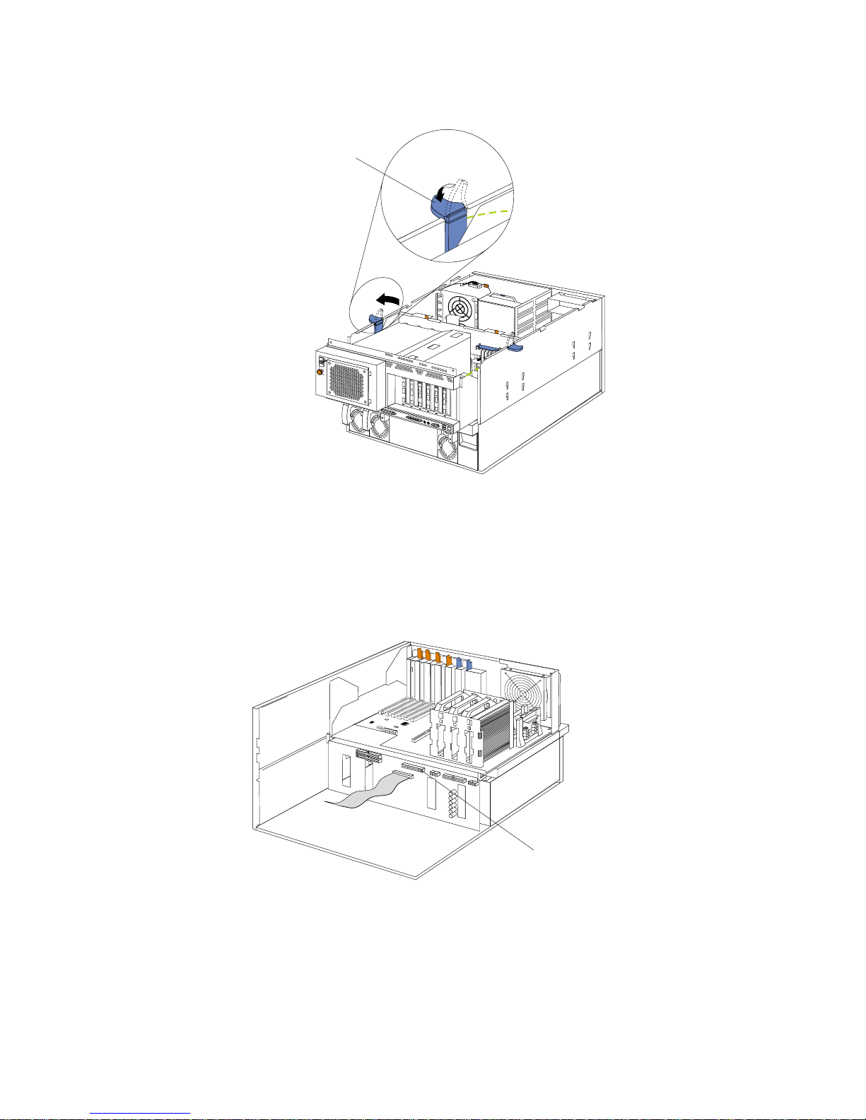
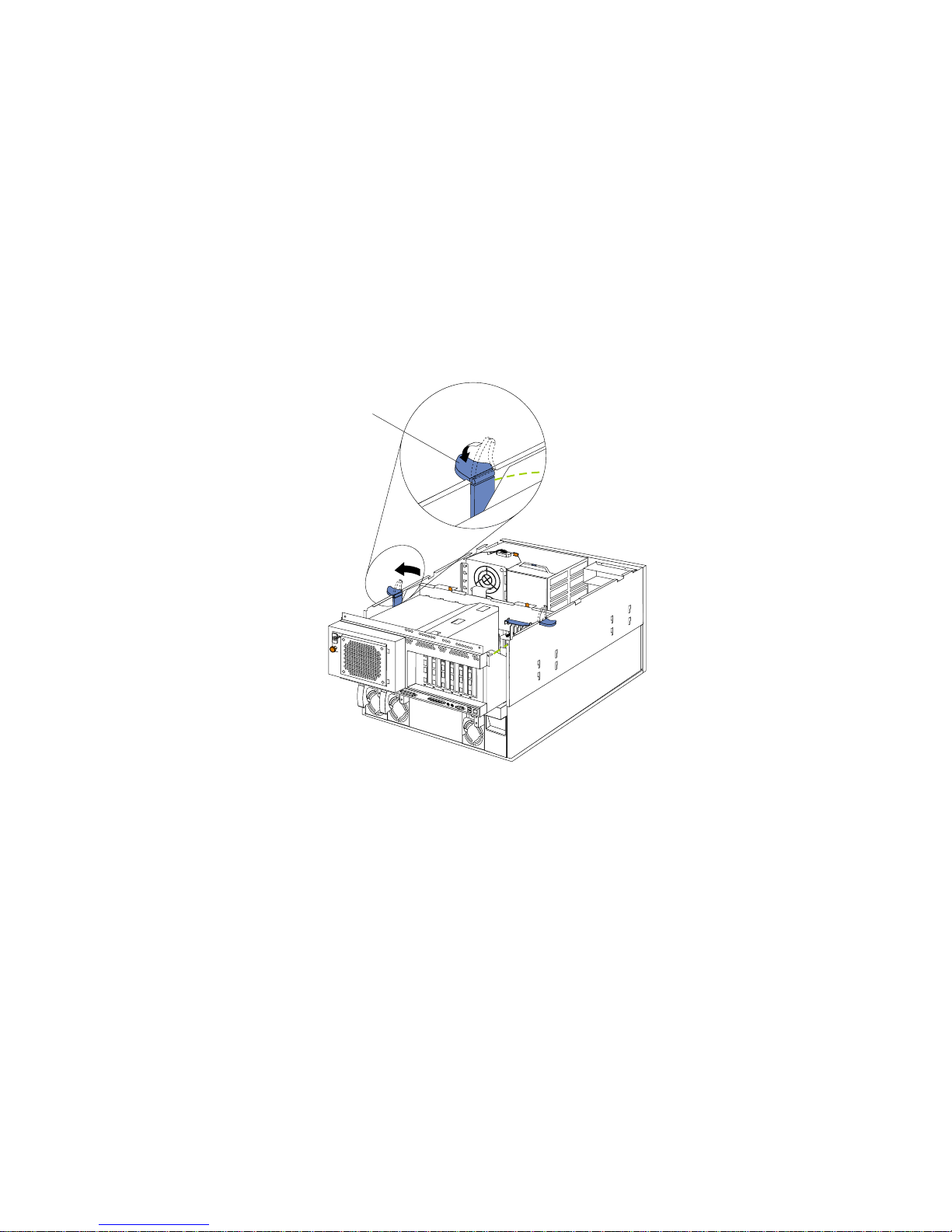
Adapter retention latch Tab
Adapter
retention latch
Adapter
Page 25

Chapter 2. Installing options 13
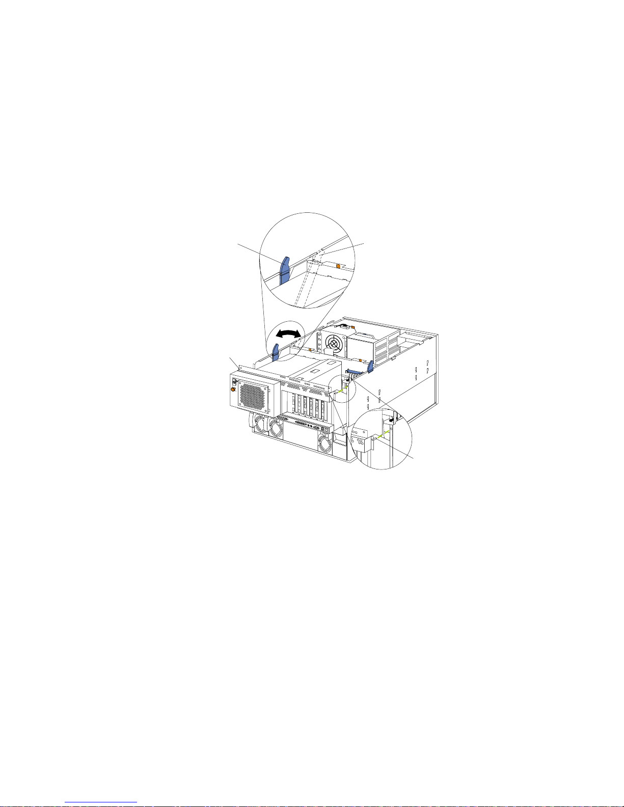
5. Remove the expansion-slot cover:
a. Rotate the adapter retention la tch counterclockwise.
b. Lift the tab covering the top of the expansion-slot cover and then remove the
expansion-slot cover from the server. Store it in a safe place for future use.
c. Press on the rear adapter retention latch (near the hard disk drives) as
indicated by the arrow on the latch and lift it to the open position.
Attention: You must install expansion-slot covers on all empty slots. This
maintains the electromagnetic emissions characteristics o f the system and
ensures proper cooling of system components.
6. Refer to the documenta tion that comes with your adapter for any cabling
instructions. It might be easier for you to route any cables before you install the
adapter.
7. Remove the adapter from the static-protective package.
Attention: Avoid touching the components and gold-edge connectors on the
adapter. If you need to put down the adapter, place the adapter, component-side
up, on a flat, static-protective surface.
8. Ins tall the adapter:
a. Carefully grasp the adapter by its top edge or upper corners, and align it with
the expansion slot on the processor board.
b. Press the a dapter firmly into the expansion slot.
Attention: When you install an adapter in the server, be sure that it is
completely and correctly seated in the expansion slot. Incomplete insertion
might cause damage to the processor board or the adapter.
c. Lower the tab over the top corner of the adapter. Rotate the adapter retention
latch clockwise until it snaps into pla c e.
d. Lower the rear adapter retention latch (near the hard disk drives) over the top
of the adapter and press on the indentation on the latch until the latch snaps
into place.
9. Connect any needed cables to the adapter.
10. Enable the PCI slot from your operating system. (Refer to the documentation that
comes with your operating system for information about enabling a hot-plug PCI
slot.) Make sure that the power light for the hot-plug PCI slot come s on.
11. If you have other options to install or remove, do so now; otherwise, go to
“Completing the installatio n” on page 36.
Page 26

14 IBM® xSeries 250: Ins ta llation Guide
Installing a non-hot-plug PCI adapter (slots 1 and 2)
The following illustration shows how to install a non-hot-plug PCI adapter.
Note: The illustrations in this document might differ slightly from your hardware.
To install a non-hot-plug PCI adapter:
Attention: When you handle static-sensitive device s, take precautions to avoid
damage from static electricity. For details on handling these devices, see “Handling
static-sensitive devices” on page 8.
1. Review the information in “Before you begin” on page 7 through “Handling
static-sensitive devices” on page 8.
2. Turn off the server; then, disconnect the power cords.
3. Remove the top cover (see “Removing the server top cover and bezel” on page 9).
4. Determine which expansion slot you will use for the adapter.
Note: PCI slots 1 an d 2 support non-hot-plug PCI adapte rs only.
5. Remove the expansion-slot cover:
a. Rotate the adapter retention la tch counterclockwise.
b. Lift the tab covering the top of the expansion-slot cover and then remove the
expansion-slot cover from the server. Store it in a safe place for future use.
c. Press on the rear adapter retention latch (near the hard disk drives) as
indicated by the arrow on the latch and lift it to the open position.
Attention: You must install expansion-slot covers on all empty slots. This
maintains the electromagnetic emissions characteristics of the system and
ensures proper cooling of system components.
Adapter retention latch Tab
Adapter
retention latch
Adapter
Page 27

Chapter 2. Installing options 15
6. Refer to the documenta tion that comes with your adapter for any cabling
instructions. It might be easier for you to route any cables before you install the
adapter.
7. Remove the adapter from the static-protective package.
Attention: Avoid touching the components and gold-edge connectors on the
adapter. If you need to put down the adapter, place the adapter, component-side
up, on a flat, static-protective surface.
8. Ins tall the adapter:
a. Carefully grasp the adapter by its top edge or upper corners, and align it with
the expansion slot on the processor board.
b. Press the a dapter firmly into the expansion slot.
Attention: When you install an adapter in the server, be sure that it is
completely and correctly seated in the expansion slot. Incomplete insertion
might cause damage to the processor board or the adapter.
c. Lower the tab over the top corner of the adapter. Rotate the adapter retention
latch clockwise until it snaps into pla c e.
d. Lower the rear adapter retention latch (near the hard disk drives) over the top
of the adapter and press on the indentation on the latch until the latch snaps
into place.
9. Connect any needed cables to the adapter and reconnect the power cords that you
disconnected in step 2 on page 14.
10. If you have other options to install or remove, do so now; otherwise, go to
“Completing the installatio n” on page 36.
Page 28

16 IBM® xSeries 250: Ins ta llation Guide
Cabling example for the ServeRAID adapter
You can install an optional IBM ServeRAID™ adapter in your server to control the
internal hot-swap hard-disk drives; that is, to enable you to configure the internal hot-
swap hard disk drives into disk arrays. Refer to your ServeRAID adapter option
documentation for additional information on:
• Installing a ServeRAID adapter in your server
• Connecting the SCSI cable to a ServeRAID adapter
• ServeRAID adapters and controllers
Select the PCI slot where you want to install the ServeRAID adapter. Before you
install the ServeRAID adapter, verify that it is compatible with the PCI slot that you
selected. Some ServeRAID adapters are not compatible with PCI slots 1 and 2. See
“Installing adapters” on page 11 for additional information on PCI slots.
The following procedure describes the cable routing that is necessary when you install
a ServeRAID adapter. You can also cable a ServeRAID adapter to external hard disk
drives.
Notes:
1. The illustrations in this document might differ slightly from your hardware.
2. Refer to the documenta tion that comes with your adapter for any cabling
instructions.
3. Cable identifiers are printed on the cables that come with your server and
options. Use these identifiers to connect the cables to the correct connectors. For
example, the hard disk drive cables are labeled "HDD".
To cable the ServeRAID adapter:
1. Determine the number of SCSI channels th at you want to use on the ServeRAID
adapter. If you are connecting to more than two SCSI channels, you might need to
purchase additional SCSI cables. Consult your IBM marketing representative or
reseller for additional information on the number and types of cables that your
server configuration requires.
As shipped, your server comes with two SCSI cables attached to the SCSI
backplane (see “Using the LVD SCSI backplane” on page 24 for details):
• One end of the first SCSI cable is attached to the SCSI channel A connector on
the SCSI backplane, and the other end is attached to the power backplane.
• One e nd of the second SCSI cable is attached to the SCSI channel B connector
on the SCSI backplane. The other end of this cable is folded and restrained
with a clamp.
If you want to connect all of the hot-swap hard disk drives to one channel, you
must install an optional SCSI repeater card as described in “Installing a SCSI
repeater card” on p age 25.
2. Review the information in “Before you begin” on page 7 through “Handling
static-sensitive devices” on page 8.
3. Turn off the server; then, disconnect the power cords.
4. Remove the top cover (see “Removing the server top cover and bezel” on page 9).
5. If you have not yet installed the ServeRAID adapter, install it now . Depending on
your server configuration, see the beginning of th is section for instructions on
installing a hot-plug or non-hot-plug adap ter; then, return here. Otherwise,
continue with the next step.
Page 29
Chapter 2. Installing options 17
6. Disconnect the shuttle:
a. Disengage the retaining levers by pressing inward.
b. Move the retaining levers back to the unlocked position.
c. Slide the shuttle toward the rear of the server until it stops.
Note: It is not necessary to remove the shuttle from the server.
7. Disconnect the SCSI cable from the SCSI connector on the power backplane.
Retaining lever
(unlocked position)
SCSI connector on
power backplane
Page 30
18 IBM® xSeries 250: Ins ta llation Guide
8. Route one end of the SCSI cable through the cable retaining clips on the SCSI
backplane.
Backplane
Retention clips
Retention clips
Power cable
connector
Cable retaining
clips
Handle
SCSI channel
A connector
SCSI channel
B connector
Guides
Page 31
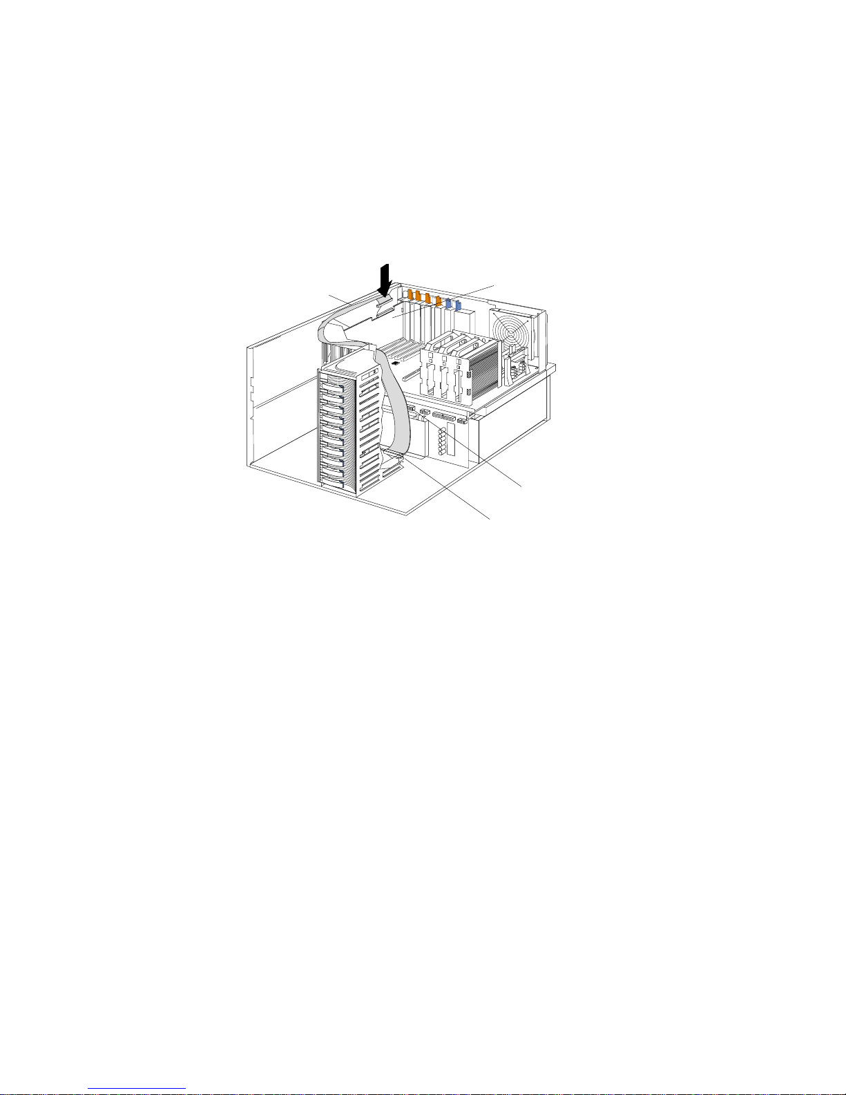
Chapter 2. Installing options 19
9. Attach one end of the SCSI cable to the selected internal SCSI channel connector
on the ServeRAID adapter. Make sure that the other end of the SCSI cable is
attached to the appropriate channel connector on the SCSI backplane.
Attention: When you route the SCSI cable, do the following:
• Do not block the ventilated space in front of the fan assembly.
• Do not place the SCSI cable fold on top of the fan assembly.
• Do not route the SCSI cable over the memory board assembly.
The following illustration shows how to route one SCSI cable to the ServeRAID
adapter.
SCSI cable
ServeRAID adapter
SCSI connector on
hard disk drive
backplane
SCSI connector on
power backplane
Page 32

20 IBM® xSeries 250: Ins ta llation Guide
10. If you are connecting to two SCSI channels, repeat step 8 on page 18 and step 9 on
page 19 for the second channel on the SCSI backplane. The following illustration
shows how to route two SCSI cables to the ServeRAID adapter.
23
SCSI
connectors
on ServeRAID
adapter
Cable
retaining
clip
Page 33

Chapter 2. Installing options 21
11. Connect the shuttle.
a. Align the tw o shuttle pins with the holes on each side of the rear of the
chassis, and disengage the retaining levers from the notches on the chassis.
b. Move the retaining levers toward the front of the server and secure the
retaining levers in the horizontal (locked) position.
12. If you have other options to install or remove, do so now; otherwise, go to
“Completing the installatio n” on page 36.
Retaining lever
(locked position)
Retaining lever
(unlocked position)
Pin
Pin
Page 34

22 IBM® xSeries 250: Ins ta llation Guide
Installing memory options
Before you install memory, review the following:
• All the DIMMs installed in each set must be the same size and speed, but all the
sets do not have to conta in DIMMs of the same size and speed.
• The memory board contains 16 DIMM connectors and supports 4-way memory
interleaving.
• Install only 3.3 V, 168-pin, 8-byte, registered DIMMs. Only 100 MHz, 72-bit,
registered, synchronous, error correcting code (ECC), SDRAM configuration
DIMM memory is supported for the 128 MB, 256 MB, 512 MB and 1 GB (when
available) DIMMs.
Note: If you install 64 MB DIM Ms, they will not support the Chipkill memory
function.
• If you install 4 GB of memory, some of the memory is reserved for system
resources. The amount reserved for system resources depends on the
configuration of the server.
• If you install 16 GB of memory, the Configuration/Setup Utility will display the
memory that is usable by the network operating system. This amount of memory
might differ from the amount of memory that you have installed.
• Installing or removing DIMMs changes the configuration information in the
server. Therefore, after installing or removing a DIMM, you must save the new
configuration information using the Configuration/Setup Utility program. See
the User’s Reference on the IBM xSeries Documentation CD for more information.
• Install the DIMMs in the order provided in Table 2.
The following illustration shows the location of the DIMM connectors.
Note: The illustrations in this book might differ slightly from your hardware.
Set of 4 DIMMs install DIMMs in these connectors:
First set (shipped as standard) J1, J5, J9, J13
2nd set J2, J6, J10, J14
3rd set J3,J 7,J 11,J 15
4th set J4, J8, J12, J16
Table 2. DIMM installation order.
Connector 1(J1) Connector 9 (J9)
Connector 10 (J10)
Connector 11 (J11)
Connector 12 (J12)
Connector 13 (J13)
Connector 14 (J14)
Connector 15 (J15)
Connector 16 (J16)
Connector 2 (J2)
Connector 3 (J3)
Connector 4 (J4)
Connector 5 (J5)
Connector 6 (J6)
Connector 7 (J7)
Connector 8 (J8)
Page 35

Chapter 2. Installing options 23
Refer to the following illustration when installing memory.
Attention: When you handle static-sensitive devices, take precautions to avoid
damage from static electricity. For details on handling these devices, see “Handling
static-sensitive devices” on page 8.
To install a memory modu le:
1. Review the information in “Before you begin” on page 7 through “Handling
static-sensitive devices” on page 8.
2. Turn off the server and remove the power cords.
3. Remove the top cover.
4. Remove the processor housing cover and remove the memory board assembly
from the server.
5. Select the connectors in which to install the DIMMs.
6. Install the DIMMs in the connectors.
7. Replace the memory board assembly in the server and replace the processor
housing cover.
8. Ins t all the top cover.
9. Connect all cables and power cords.
Pop rivets
Processor housing
cover
DIMM
Memory board
Page 36

24 IBM® xSeries 250: Ins ta llation Guide
Using the LVD SCSI backplane
Your server contains hardware that enables you to replace a failed hard disk drive
without turning off the server. Therefore, you have the advantage of continuing to
operate your system while a hard disk drive is removed or installed. These drives are
known as hot-swap drives. The hot-swap drives are attached to a hot-swap hard disk
drive backplane. The backplane is a printed circuit board behind the drive bays. For
more information on drive bays, refer to the User’s Reference on the IBM xSeries
Documentation CD. For details on drive installation, see “Installing a drive in a hot-
swap bay” on page 31.
As shipped, the LVD SCSI hot-swap hard disk drive backplane supports a split, dualchannel configuration. You can install a maximum of 10 slim-high, hot-swap hard
disk drives. You can attach five drives to each half of the backplane. These drives must
be low voltage differential (LVD) hard disk drives that operate at 160 MB per second
or lower.
You can configure the channels on the SCSI backplane in one of two ways:
• You can configure each SCSI channel (bus) independently. This is the standard
backplane configuration. In this configuration:
— The hard disk drives in the upper half of the backplane are attached to
channel A through a SCSI cable that comes attached to the SCSI backplane.
— The hard disk drives in the lower half of the backplane are attached to
channel B through a second optional SCSI cable. One end of this second SCSI
cable comes attached to the SCSI channel B connector on the backplane. The
other end of this cable is folded and restrained with a clamp.
When you are installing hot-swap hard disk drives in the standard backplane
configuration, attach the first five to channel A; then, attach the remainder to
channel B. Refer to the illustration in this section for the SCSI channel connector
locations.
• You can choose to configure the SCSI backplane as a single 10-drive SCS I channel.
To do this, you must install an optional SCSI repeater card as described in
“Installing a SCSI repeater card” on page 25.
Notes:
1. The LVD SCSI backplane is also known as the SCSI backplane or the hot-swap
hard disk drive backplane.
2. Refer to the User’s Refer e nce on the IBM xSeries Documentation CD for the SCSI
identifiers (IDs) for the LVD SCSI backplane and the hot-swap hard disk drives
that are attached to SCSI channels A and B.
3. Carefully route all cables so that they do not become damaged.
4. Cable identifiers are printed on the cables that come with your server and
options. Use these identifiers to connect the cables to the correct connectors. For
example, the hard disk drive cables are labeled "HDD".
5. For information on cabling options and using the LVD SCSI backplane, refer to
the documentation that comes with th e option kit.
6. For additiona l information on cabling the ServeRAID ada pter, see “Cabling
example for the ServeRAID adapter” on page 16.
7. The illustrations in this document might differ slightly from your hardware.
Page 37

Chapter 2. Installing options 25
The following illustration sho ws the main SCSI backplane component locations.
Installing a SCSI repeater car d
You must install an optional SCSI repeater card to connect all of your internal hotswap hard disk drives to the same SCSI channel.
The following illustration shows the rear connectors on the optional SCSI repeater
card, as viewed from the rear of the server.
Backplane
Retention clips
Retention clips
Power cable
connector
Cable retaining
clips
Handle
SCSI channel
A connector
SCSI channel
B connector
Guides
SCSI cable
connector
SCSI repeater
card cable
connector
Page 38
26 IBM® xSeries 250: Ins ta llation Guide
To install a SCSI repeater card:
Attention: When you handle static-sensitive device s, take precautions to avoid
damage from static electricity. For details on handling these devices, see “Handling
static-sensitive devices” on page 8.
1. Review the information in “Before you begin” on page 7 through “Handling
static-sensitive devices” on page 8.
2. Turn off the server and peripheral devices, and disconnect all power cords and
external cables; then, remove the top cover (see “Removing the server top cover
and bezel” on page 9).
3. If a ServeRAID adapter is installed in the server, disconnect the SCSI cable from
the adapter (see “Cabling example for the ServeRAID adapter” on page 16).
4. Disconnect the shuttle:
a. Disengage the retaining levers by pressing inward.
b. Move the retaining levers back to the unlocked position.
c. Slide the shuttle toward the rear of the server until it stops.
Note: It is not necessary to remove the shuttle from the server.
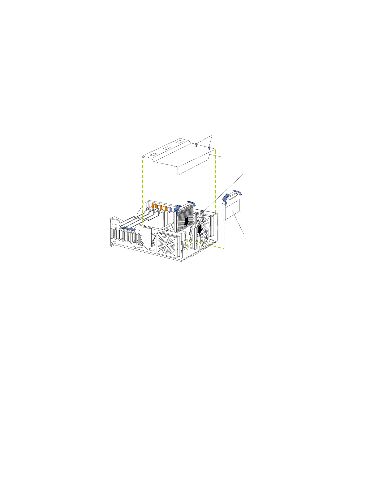
5. Remove fan assembly 1 from the server.
6. Disconnect the hot-swap hard disk drives from the corresponding SCSI backplane
connectors; then, pull the drives forward.
Note: It is not necessary to remove the drives from the server.
7. Remove the SCSI backplane from the server:
a. Lift the SCSI backplane guides from the corresponding slots on the server;
then, slide the SCSI backplane upward.
b. Disconnect the power cable from the SCSI backplane.
c. Disconnect the SCSI cables from the channel A and B connectors on the SCSI
backplane.
d. Lift the SCSI backplane from the server.
Retaining lever
(unlocked position)
Page 39

Chapter 2. Installing options 27
8. Touch the static-protective package that contains the repeater card option to any
unpainted metal surface on the server; then, remove the repeater card option from
the package.
Note: If necessary, refer to the documentation that comes with the repeater card
option kit to assemble the repeater card option.
9. Connect the repeater card option to the SCSI backplane:
a. Align the corresponding connecto rs on the repeater card and the SCSI
backplane. The corresponding screw holes on the repeater card and the SCSI
backplane will automatically align.
b. Use a small, flat-blade screwdriver to connect the repeater card to the SCSI
backplane with the two screws from the repeater card option kit.
c. Secure the repeater card with the retention clips on the SCSI channel A
connector on the SCSI backplane.
Backplane
SCSI repeater card
screws
Retention clips
Page 40

28 IBM® xSeries 250: Ins ta llation Guide
10. A short SCSI cable comes with the repeater card option kit.
a. Connect one end of this cable to the repeater card.
b. Connect the other end of the cable to the SCSI channel B connector on the
SCSI backplane.
c. Secure both cable ends with the retention clips on the SCSI connectors.
SCSI cable to
power backplane
SCSI backplane
SCSI repeater card
SCSI repeater
card cable
Page 41

Chapter 2. Installing options 29
11. Reinstall the SCSI backplane in the server:
a. Reconnect the power cable to the S CSI backplane.
b. Align the SCSI backplane guides with the corresponding slots on the server.
c. Slide the SCSI backplane into the server.
d. Connect one end of the SCSI cable to the repeater card.
e. Make sure that the other end of the SCSI cable is attached to the power
backplane located on the rear of the shuttle.
SCSI
backplane
SCSI
repeater
card
SCSI connector on
power backplane
Page 42
30 IBM® xSeries 250: Ins ta llation Guide
12. Slide the hot-swap hard disk drives back into place in the drive bays. If you need
to install additional hot-swap drives, do so now (see “Installing a drive in a hotswap bay” on page 31). Y o u can connect a maximum of 10 har d disk drives to the
SCSI backplane.
Note: After you connect these hard disk drives to the SCSI backplane, the
backplane sets the SCSI IDs for the backplane and the hard disk drives.
Refer to the User’s Reference on the IBM xSeries Document atio n CD for
additional information.
13. Reinstall fan assembly 1 in the server.
14. Reconnect the shuttle.
a. Align the tw o shuttle pins with the holes on each side of the rear of the
chassis, and disengage the retaining levers from the notches on the chassis.
b. Move the retaining levers toward the front of the server, and secure the
retaining levers in the horizontal (locked) position.
15. If you disconnected the SCSI cable from the ServeRAID adapter in step 3 on page
26, reconnect the SCSI cable to the adapter.
16. If you have other options to install or remove, do so now; otherwise, go to
“Completing the installatio n” on page 36.
Retaining lever
(locked position)
Retaining lever
(unlocked position)
Pin
Pin
Page 43

Chapter 2. Installing options 31
Installing a drive in a hot-swap bay
Y o ur server supports 10 1-inch (26 mm) slim-high, 3.5-inch hot-swap hard disk drives
in the hot-swap bays. These drives must be LVD hard disk drives that operate at 160
MB per second or lower.
Note: Refer to the User’s Reference on the IBM xSeries Documentation CD for
information on installing devices in the non-hot-swa p bays.
Attention: If you are replacing a drive that is part of a RAID level 1 or RAID level 5
logical drive, ensure that you install the replacement drive in the correct bay. Failure
to replace the drives in their correct bays can result in loss of data.
Refer to the following illustration when installing a hot-swap drive. The server comes
with a gap filler installed at the top of the hot-swap hard disk drive bays. You cannot
install a drive in the gap. Some gap fillers also come attached to a slim filler panel. The
gap filler is removable from the slim filler panel, when available.
Note: The illustrations in this book might differ slightly from your hardware.
Attention: When you handle static-sensitive devices, take precautions to avoid
damage from static electricity. For details on handling these devices, see “Handling
static-sensitive devices” on page 8.
To install a drive in a hot-swap bay:
1. Review the information in “Before you begin” on page 7 through “Handling
static-sensitive devices” on page 8.
2. Remove the slim fi ller panel from one of the empty hot-swap bays by inserting
your finger into the depression at the left side of the filler panel and pulling it
away from the server.
Attention: To maintain proper system cooling, do not operate the server for more
than 10 minutes without either a drive or a filler panel installed for each bay.
Slim
filler panel
Gap filler
Drive tray handle
(in open position)
Gap filler
Page 44

32 IBM® xSeries 250: Ins ta llation Guide
3. Install the hard disk drive in the hot-swap bay:
a. If there is a small gap above or below the d r ive, separate the gap filler from
the slim filler panel and insert it in the gap.
Note: A drive placement guide is located on the inside edge of the bezel. The
drive placement guide indicates the placement for slim-high drives.
The guide also shows the SCSI ID assigned to the drive.
b. Ensure that the tray handle is open (that is, perpendicular to the drive).
c. Align the drive assembly with the guide rails in the ba y.
d. Gently push the drive assembly into the bay until the drive stops.
e. Push the tray handle to the closed (locked) position.
f. Check the hard disk drive status indicators to verify that the hard disk drive
is operating properly.
If the amber hard-disk status light for a drive is lit continuously, that
individual drive is faulty and needs to be replaced. If the green hard-disk
activity light is flashing, the drive is being accessed.
Note: If your server has an optional ServeRAID adapter installed, you must
configure your disk arrays after installing hard disk drives. Refer to the
information that comes with your ServeRAID adapter for details.
Page 45
Chapter 2. Installing options 33
Installing a micr oprocessor
Your server comes with one microprocessor installed in connector J2. This is the
startup (boot) microprocessor. A microprocessor installed in connector J3 is
microprocessor 2; a microprocessor installed in connector J4 is microprocessor 3; a
microprocessor installed in connector J5 is processor 4. If more than one
microprocessor is installed, the highest numbered microprocessor is the one from
which the server will start. The lower numbered microprocessors are used as
application microprocessors.
Note: The illustrations in this document might differ slightly from your hardware.
Attention: When you handle static-sensitive devices, take precautions to avoid
damage from static electricity. For details on handling these devices, see “Handling
static-sensitive devices” on page 8.
To install an additional microprocessor kit:
1. Review the information in “Before you begin” on page 7 through “Handling
static-sensitive devices” on page 8.
2. Turn off the server and remove the power cords.
3. Remove the top cover.
4. Remove the processor housing cover.
5. Remove the terminator card from the connector.
6. Inst all the microprocessor.
Note: Each microprocessor connector must contain either a terminator card or a
microprocessor.
7. Instal l the voltage regulator module (VRM).
8. Install the process or housing cover.
9. Ins t all the top cover (see “Completing the installation” on page 36).
10. Cable the server and connect all power cords.
Pop rivets
Terminator card
VRM
Processor housing
cover
Page 46
34 IBM® xSeries 250: Ins ta llation Guide
Installing a hot-swap power supply
Before you continue with the power supply-installation procedure, review the
following.
Notes:
1. During normal operation, each power supply bay must have either a power
supply or filler panel installed for proper cooling.
2. Before you install a power supply in the right-most power supply bay, you must
disconnect the cable-management arm. You can reconnect the cable-management
arm after installing the power supply.
If you install or remove a power supply, observe the following precautions:
The illustrations in this document might differ slightly f rom your ha rdware.
Attention: When you handle static-sensitive device s, take precautions to avoid
damage from static electricity. For details on handling these devices, see “Handling
static-sensitive devices” on page 8.
Statement 8
CAUTION:
Never remove the cover on a power supply or any part that has the following label attached.
Hazardous voltage, current, and energy levels are present inside any component that has this
label attached. T here are no serviceable parts inside these components. If you suspect a
problem with one of these parts, contact a service technician.
Page 47
Chapter 2. Installing options 35
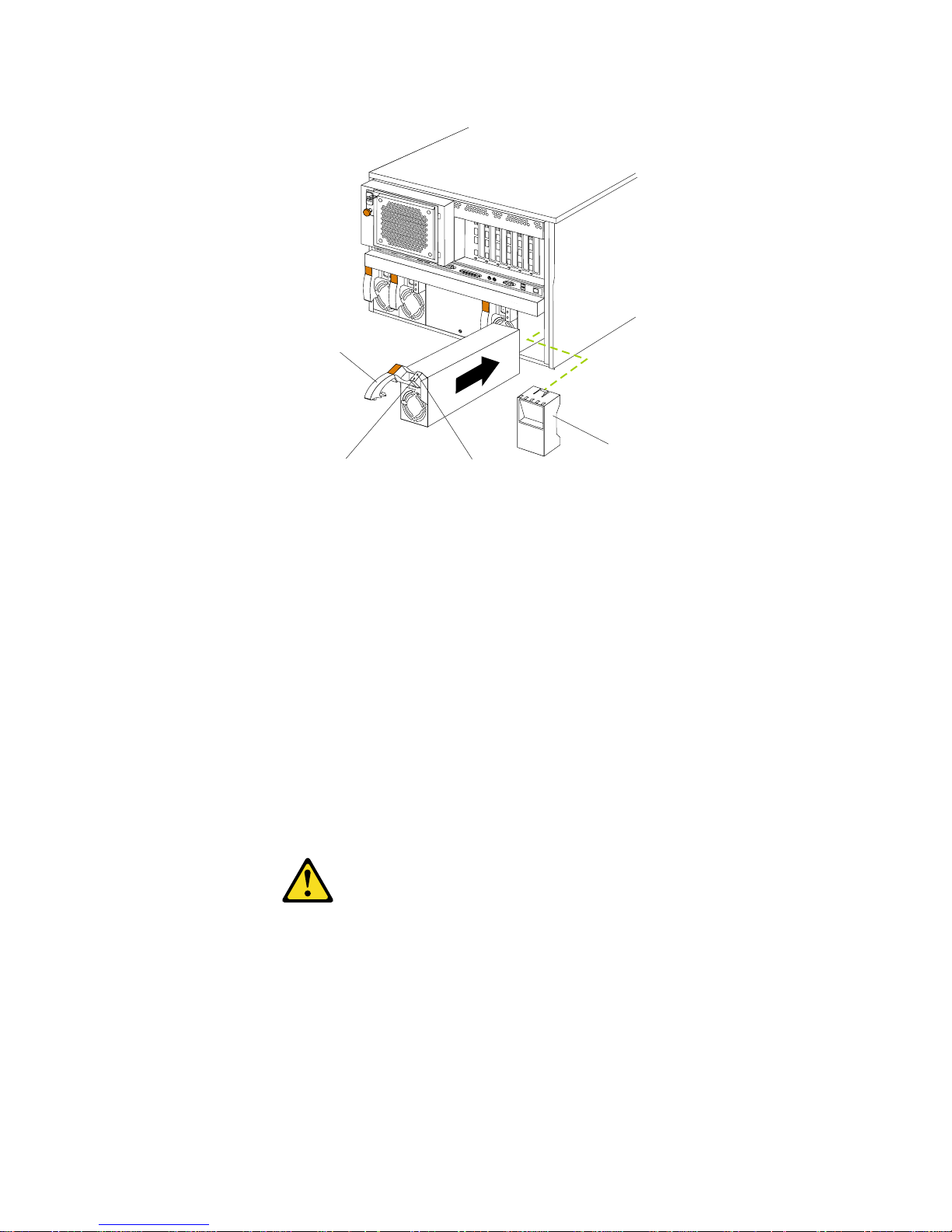
To install an additional power supply:
1. Review the information in “Before you begin” on page 7 through “Handling
static-sensitive devices” on page 8.
2. Remove the filler panel.
3. Place the handle on the power supply in the open position.
4. Slide the power supply into the chassis and press the handle to the closed
position.
5. Plug one end of the power cord into the corresponding outlet on the rear of the
server; then, plug the other end of the power cord into a properly grounded
electrical outlet.
6. Verify that the DC Power light and the AC Power light on the power supply are
lit, indicating that the power supply is operati ng properly.
Statement 6
CAUTION:
If you install a strain-relief bracket option ov er the end of the pow er cord that is con nected
to the device, you must connect the other end of the power cord to an easily accessible
power source.
AC power lightDC power light
Handle
Filler panel
Page 48

36 IBM® xSeries 250: Ins ta llation Guide
Completing the installation
To complete your installation, you must reinstall the media bay bezel, reinstall the top
cover, reconnect all the cables that you disconnected, and for certain options, run the
Configuration/Setup Utility program. Follow the instructions in this section.
Attention: For proper cooling and airflow, install the top cover before turning on the
server. Operating the server for extended periods of time (over 30 minutes) with the
top cover removed might damage server components.
Installing the media-bay be zel
Refer to the following illustration to install the media-bay bezel.
Note: The illustrations in this book might differ slightly from your hardware.
To install the medi a-bay bezel:
1. Insert the two tabs on the top of the media-bay bezel into the matching h oles on
the server chassis.
2. Push the bottom of the media-bay bezel toward the server until the two tabs at the
bottom of the bezel snap into place.
Media-bay bezel
Page 49

Chapter 2. Installing options 37
Installing the top cover
To install the server top cover:
1. Before installing the cover, check that all cables, adapters, and other components
are installed and seated correctly and that you have not lef t loose tools or parts
inside the server.
2. Lower the cover with the rear edge of the cover about 25 mm (1 inch) back from
the rear edge of the server.
3. Slide the cover forward.
4. Tighten the two captive screws on the back edge of the cover.
5. If you disconnected any cables from the back of the server, reconnect the cables;
then, plug the power cords into properly grounded electrical outlets.
Note: If necessary, see “Cabling the server” on page 38 for connector locations.
Reconfiguring the server
When you start your server for the first time after you add or remove an internal
option or an external SCSI device, you might see a message telling you that the
configuration has changed. Run the Configuration/Setup Utility program to save the
new configuration information. See “Chapter 4. Configuring your server ,” on page 45.
Some options have device drivers that you need to install. Refer to the documentation
that comes with your option for information about installing any required device
drivers.
If you have installed a new microprocessor, you might want to upgrade your
operating system to support symmetric multiprocessing (SMP). Refer to the User’s
Reference on the IBM xSeries Documentation CD for additional information.
If you have installed or removed a har d disk drive, r efer to the information that comes
with your ServeRAID adapter for details on configuring your disk arrays.
Captive screws
Top cover
Page 50

38 IBM® xSeries 250: Ins ta llation Guide
Cabling the server
Refer to the following illustration for the location of the input and output connectors
on your server.
The illustrations in this document might differ slightly f rom your ha rdware.
Refer to the following illustration for an example of proper cable routing.
Note: Refer to the Rack Installation Instructions for rack installation instructions.
Ethernet
USB1
USB2
Video
Mouse
Keyboard
Ultra2 SCSI
ASM Interconnect
port B
ASM Interconnect
port A
Serial A
Serial B
System management
Parallel
Advanced Systems
Management Interconnect knockout
Page 51

© Copyright IBM Corp. 2001 39
Chapter 3. Server power, controls, and indicators
Use the following procedure to start your server.
1. Turn on all extern al devices , such as the monitor.
Note: After you plug the power cord into an outlet, wait 20 seconds before
pressing the power control button. During this time, the power control
button will not respond beca use the system management microprocessor
is being initialized.
2. Press the power control button on the front of the server. The power-on light
comes on, and the power-on self-test (POST) begins.
Turning on the server
Turning on the server refers to the act of plugging the power cord of your server into
the power source and starting the operating system.
The server can start in any of the following ways:
• You can press the power-control button on the front of the se rver to start the
server.
Notes:
1. You can install a circular disk over the power-control button to prevent
accidental manual power-off. This disk, known as the power-control button
shield, comes with your server.
2. After you plug the power cord of your server into an electrical outlet, wait
approximately 20 seconds before pressing the power-control button. During
this time, the Advanced System Managemen t processor is initializing;
therefore, the power-control button does not respond.
• If the server is turned on and a power failure occurs, the server will start
automatically when power is restored.
• If the server is turned on, a power failure occurs, and unattended-start mode is
enabled in the Configuration/Setup Uti lity program, the server will start
automatically when power is restored.
• If AC power is present, the server is off, and the wake-up feature is enabled in the
Configuration/Setup Utility program, the wake-up feature will turn on the server
at the set time.
• If AC power is present, the server is off, and ring-signal detect is enabled in the
Configuration/Setup Utility program, you can turn on the server by telephone
input.
• If your operating system supports the system-managem en t software, the systemmanagement softwa re can turn on the server.
• If your operating system supports the Wake on LAN feature, the Wake on LAN
feature will turn on the server at the set time.
Note: For more detailed information about the Wake on LAN feature, refer to the
documentation that comes with the Wake on LAN adapter and cables.
Page 52

40 IBM® xSeries 250: Ins ta llation Guide
Turning off the server
Turning off the server refers to the act of disconnecting the server from the power
source.
You can turn off the server in any of the following wa ys:
• You can press the power-control button on the front of the server. If this feature is
supported by your operating system, this starts an orderly shutdown of the
operating system, and places the server in standby mode.
Note: After turning off the server, wait at least five seconds before you press the
power-control button to turn on the server again.
• You might need to press and hold the power-control button for more than four
seconds to cause an immediate shutdown of the server and to force the power off.
You can use this feature if the operating system stops functioning.
• You can disconnect the server power cords from the electrical outlets to shut off
all power to the server.
Note: After disconnecting the power cords, wait about 15 seconds for your
system to stop running. Watch for the power-on light on the information
panel to stop blinking.
Statement 5
CAUTION:
The power control button on the device and the power switch on the power
supply do not turn off the electrical current supplied to the device. The device
also migh t have more th an one power cord. To remove all electrical current f r om
the device, ensure that all power cords are disconnected from the power source.
1
2
3
Page 53

Chapter 3. Server pow e r, con t rols, and indicators 41
Server controls and indicators
Note: The illustrations in this document might differ slightly from your hardware.
The following illustration shows the controls and indicators on the server.
T
Hard-disk drive status light: Each hot-swap drive has a status light. When this
amber light is on continuously, the drive has failed. If an optional IBM
ServeRAID™ adapter is installed in the server, when the light flashes slowly (one
flash per second), the drive is being rebuilt. When the light flashes rapidly (three
flashes per second), the controller is identifying the drive.
Hard-disk drive activi ty ligh t: Each hot-swap drive has a hard-disk activity light.
When this green light is flashing, the drive is being accessed.
CD-ROM eject/load button: Press this button to eject or retract the CD-ROM tray.
CD-ROM drive in-use light: When this light is on, the CD-ROM drive is being
accessed.
Diskette-eject button: Press this button to eject a diskette from the drive.
Diskette drive in-use light: When this light is on, the diskette drive is being
accessed.
Reset button: Press this button to reset the server and run the power-on self-test
(POST).
Power control button: Press this button to manually turn on or off the server.
Information LED panel
Power-control button
Reset button
Diskette drive in-use light
Diskette-eject button
CD-ROM eject/load button
CD-ROM drive in-use light
Hard-disk drive
activity light
Hard-disk
status light
drive
Page 54

42 IBM® xSeries 250: Ins ta llation Guide
Information LED panel: The lights on this panel give status information for your
server. See “Information LED panel” on page 43.
Statement 5
CAUTION:
The power control button on the device and the power supply do not turn off the
electrical current supplied to the device. The device also might have more than one
power cord. To remove all electrical current from the device, ensure that all power cords
are disconnected from the power source.
1
2
3
Page 55

Chapter 3. Server pow e r, con t rols, and indicators 43
Information LED panel
The following illustration shows the status lights on the Information LED panel.
System error light: This amber light is on when a system error occurs. A light on
the diagnostics LED panel will also be on to further isola te the error. (For more
information, see the User’s Reference on the IBM xSeries Documen tatio n CD.)
Information light: When this amber ligh t is on, the server power supplies are
nonredundant or some other noncritical event has occurred. The event is recorded
in the Event log. See the User’s Reference on the IBM xSeries Documentation CD for
instructions on viewing the Event log.
Ethernet transmit/receive activ it y light: When this green light is on, there is
activity between the server and the network.
Ethernet-link status light: When this green light is on, there is an active
connection on the Ethernet port.
Ethernet speed 100 Mbps light: When this gr een light is on, th e Ethern et speed is
100 Mbps. When the light is off, the Ethernet speed is 10 Mbps.
Processor activity lights: One or more of these green lights are on when there is
microprocessor activity. The number of lights that are on indicates the number of
microprocessors with activity .
Hard-disk drive activity li ght: This gr een light flickers when there is activity on a
hard disk drive.
System power light: When this green light is on, power is present in the server.
When this light flashes, the server is in standby mode (the system power supply is
turned off and ac current is present). When this light is off, the power subsystem,
the ac power, or a light has failed.
Attention: If the system power light is off, it does not mean there is no electrical
current present in the server. The light might be burned out. To remove all
electrical current from the server, you must unplug the server power cords from
the electrical outlets or from the uninterruptible power device.
POST-complete light: This green light is on when the power-on self-test (POST)
completes without any errors.
100
MB
LINK
OK
TX
RX
OK
1 2 3 4
POST-complete
System power
Hard disk drive
activity
Processor
activity
Ethernet speed Ethernet-link
status
Ethernet
transmit/receive
activity
Information
System error
Page 56

44 IBM® xSeries 250: Ins ta llation Guide
Page 57

© Copyright IBM Corp. 2001 45
Chapter 4. Configuring your server
The ServerGuide CDs provide software setup tools and installation tools that are
specifically designed for your IBM xSeries server. Use these CDs during the initial
installation of your server to configure basic hardware features and to simplify your
network operating system installation. (See “Using the ServerGuide CDs” for more
information . ) T h e Se r ve r G u ide CDs also co nt ai n a c o ll e c t i on of applicatio n programs,
which you can install after your server is up and runn ing.
In addition to the ServerGuide CDs, you can use the following configuration
programs to customize your server hardware:
• Configuration/Setup Utility
The Configuration/Setup Utility program is part of the basic input/output system
(BIOS) code that comes with your server. You can use this program to configure
serial and parallel port assignments, change interrupt request (IRQ) settings,
change the drive startup sequence, set the date and time, and set passwords.
• SCSISelect Utility
With the built-in SCSISelect Utility program, you can configure the devices that
are attached to the integrated SCSI controller. Use this program to change default
values, resolve configuration conflicts, and perform a low-level format on a SCSI
hard disk drive.
• ServeRAID programs
If you have a ServeRAID adapter installed in your server, you must use the
ServeRAID configuration program to define and configure your disk-array
subsystem before you install your operating system.
Note: Refer to the User’s Reference on the IBM xSeries Documentation CD for detailed
instructions for using the configuration programs.
Using the ServerGuide CDs
The ServerGuide CDs provide state-of-the-art programs to detect the server model
and hardwa re options that are installed, configure xSeries server hardware, p ro vide
device drivers, and install your network operating system (NOS).
Note: If the ServerGuide CD does not start, see “ServerGuide startup problems” on
page 50.
1. Insert the Setup and Installation CD, and restart the server.
2. Follow the instructions on the screens to:
a. Select your language.
b. Select your keyboard layout and country.
c. View the Overview to learn about ServerGuide features.
d. View the README file to review installation tips about your NOS and
adapter.
e. Start the setup a nd ha rdware configuration programs.
f. Start the NOS installation. You will need your copy of the NOS CD.
Note: For information on the supported NOS versions, refer to the Setup and
Installation CD label.
Page 58

46 IBM® xSeries 250: Ins ta llation Guide
Page 59

© Copyright IBM Corp. 2001 47
Chapter 5. Solving problems
This section provides basic troubleshooting information to help you resolve some
common problems that might occur while setting up yo ur server.
If you cannot locate and correct the problem using the information in this section,
refer to the " Solving problems" section on the IBM xSeries Docum e ntation CD and the
"Support for Servers" flowchart in the front of this booklet.
POST beep code descriptions
POST emits one beep to signal successful completion. If POST detects a problem
during startup, other beep codes might occur. You can use the following beep code
descriptions to help identify and resolve problems that are detected during startup.
Note: See the "Solving problems" section of the User’s Reference on the IBM xSeries
Documentation CD for more information about the POST beep codes.
Beep code Descriptions of the POST beep codes
No beep Call for service.
Continuous If no video appears, the startup microprocessor failed. Verify that the startup microprocessor is
installed correctly. If it is, replace the startup microprocessor. If the problem persists, call for
service.
One short POST completed successfully. One beep also occurs after POST if you enter an incorrect password.
Two short Follow the instructions that appear on the screen.
Three short POST detected a system memory error. Verify that the memory is installed correctly. If it is, replace
the failing memory module.
Repeating
short
The system board might contain a failing component.
1. Verify that the keyboard and pointing devices are connected properly.
2. Ensure that nothing is resting on the keyboard.
3. Disconnect the pointing device; then, restart the server. If the problem goes away, replace the
pointing device. If the problem remains, call for service.
One long and
one short
If the video controller on the system board is being used, call for service. If you installed an
optional video adapter, replace the failing adapter.
One long and
two short
A video I/O adapter ROM is not readable, or the video subsystem is defective. If you installed an
optional video adapter, replace the failing adapter. If the problem remains, call for service.
One long and
three short
The system-board video subsystem has not detected a monitor connection to the server. Ensure
that the monitor is connected to the server. If the problem persists, replace the monitor.
Two long and
two short
POST does not support the optional video adapter. Replace the optional video adapter with one
that is supported by the server or use the integrated video controller.
All other beep
codes
1. Verify that the system memory modules are installed correctly.
2. Tun off the server; then, restart the server. If the problem remains, call for service.
Table 3. POST beep code descriptions.
Page 60

48 IBM® xSeries 250 In st allation Guide
POST error messages
The following table provides an abbreviated list of the error messages that might
appear during POST.
Note: See the "Solving problems" section of the User’s Reference on the IBM xSeries
Documentation CD for more information about the POST beep codes.
Page 61

Chapter 5. Solving problems 49
POST message Failing device or problem found Suggested action
129 L1 cache of a microprocessor Check the in st al lation of your microprocessors.
162 Change in device configuration Verify that your optional devices are turned on and
installed correctly.
163 Time of day has not been set Set the correct date and time.
164 Change in memory configuration Verify that your memo ry is in stalled pr operly; then, r estart
the server and run the Configuration/Setup Utility
program.
201 Change in memory configuration Verify that your memory is fully seated and installed
properly.
229 L2 cache of a microprocessor Check the in st al lation of your microprocessors.
289 Failing DIMM was disabled V eri fy that your me mory is correc t for your server an d that
it is installed properly.
301
303
Keyboard and keyboard controller Ensure that the keyb oard cable is conn ected and noth ing is
resting on the keyboar d keys.
962 Parallel port configuration error Start the Configuration/Se tup program an d verify that the
parallel-port setting is correct.
11xx Serial port error Verify that the serial cable is connected correctly.
1162 Serial port configuration conflict Start the Configuration/Setup program and ensure that
the IRQ and I/O port assignments needed by the serial
port are available.
1601 BIOS code update needed Download and install the latest system BIOS level.
1800 PCI adapter hardware interrupt Start the Configuration/ Setup pr ogram an d verify th at the
interrupt resource settings are correct.
2400
2462
Video controller and memory Verify that the monitor is connected correctly.
00019xxx Processor x is not functioning or
failed the built-in test
Verify that processor x is install e d cor rectly. If the problem
remains, replace processor x.
00180xxx A PCI adapter requested a resource
that is not available
Start the Configuration/Setup program and ensure that
the resources needed by the PCI adapter are available.
012980xx
012981xx
Data for processor x Download and install the latest system BIOS level.
01298200 Microprocessor speed mismatch Install microprocessors with identical speeds.
I9990305 POST could not find an ope rating
system.
Install your operating system.
Table 4. Abbreviated list of POST error messages.
Page 62

50 IBM® xSeries 250 In st allation Guide
ServerGuide startup problems
Look for the symptom in the left column of the ch art. Probable solutions to the
problem are in the right column.
Setup and
Installation CD
Action
Setup and
Installation CD will
not start.
• Ensure that the system is a su pport ed serv er mo del w ith a st a rt ab le
(bootable) CD-ROM drive.
• If the startup (boot) sequence settings have been altered , be sure
that the CD-ROM is first in the startup sequence.
• If more than one CD-ROM drive is installed, be sure that only one
drive is set as the primary drive. Start the CD from the primary
drive.
ServeRAID
program cannot
view all installed
drives or cannot
install NOS.
• Ensure that there are no duplicate SCSI IDs or IRQ assignments.
• Ensure that the hard disk drive is connected properly.
The operating
system installation
program
continuously
loops.
Free up more space on the hard disk.
ServerGuide will
not start your NOS
CD.
Ensure that the NOS CD is supported by ServerGuide. See the Setup and
Installation CD label for a list of supported NOS versions.
Cannot install
NOS.
Ensure that the NOS is supported on your server. If the NOS is
supported, either there is no logical drive defined (ServeRAID systems)
or the ServerGuide System Partiti on is not pr esent. Run t he ServerGuide
setup and configuration program and ensure that the setup is complete.
System Updates
and Applications
CD
Action
Get "time out" or
"Unknown host"
errors.
Ensure that you have access to the Internet through FTP directly.
Page 63

Chapter 5. Solving problems 51
Troubleshooting chart
Notes:
1. Refer to the "Solving problems" section of the User’s Reference on the IBM xSeries
Documentation CD for more detailed troubleshooting charts.
2. If you cannot find the problem in the troubleshooting charts, run the diagnostic
programs. If you have run the diagnostic test programs, or if running the tests
does not reveal the problem, call for service.
Monitor problems Suggested action
Testing Some IBM monitors have their own self-tests. If you suspect a problem with your
monitor, refer to the information that comes with the moni tor for adjusting and
testing instructions.
If you still cannot find the problem, call for service.
The screen is blank. Verify that:
1. The server power cord is plugged into the server and a working electrical
outlet.
2. The m onitor cables are connected properly.
3. The monitor is turned on , and the Brigh tness and Contrast con trols are a djusted
correctly.
If the items above are correct and the screen remains blank, call for service.
Only the cursor appears. Call for service.
The monitor works when you
turn on the server, but goes
blank when you start some
application programs.
Verify that:
1. The primary monitor cable is connected to the video port.
2. You installed the necessary dev ic e drivers for the applic at ions .
If the items above are correct and the screen remains blank, call for service.
Wavy, unreadable, rolling,
distorted screen, or screen jitter.
If the monitor se lf-tests show the mon itor is OK, consider the location of the
monitor. Magnetic fields around other devices (such as transformers, appliances,
fluorescent lights, and other monitors) can cause screen jitter or wavy, unreadable,
rolling, or distorted screen images. If this happens, turn off the monitor. (Moving a
color monitor while it is turned o n might cause scr een disc oloration.) Then move t he
device and the moni to r at least 305 mm (12 in.) ap art. Turn on the monitor.
Notes:
1. To prevent diskette drive read/ writ e err or s, be sur e that the distanc e between
monitors and diskette drives is at least 76 mm (3 in.).
2. Non-IBM monitor cables might cause unpredictable problems.
3. An enhanced monitor cable with additional shielding is available for the 9521
and 9527 monitors. For information about the enh anced monitor cable, see your
IBM reseller or IBM marketing representative.
If the problem remains, call for serv ice.
W r on g char act ers app ear o n the
screen.
If the wrong la nguage is displ aye d, upd ate the BIOS code with th e cor re ct l anguag e.
If the problem remains, call for serv ice.
Page 64

52 IBM® xSeries 250 In st allation Guide
Power problems Suggested action
The server does not power on. Ve rify that :
1. The power cables are properly connected to the server.
2. The electrical outlet functions properly.
3. The type of memory that is installed is correct.
4. If you just installed an option, remove it , and re s ta rt the server. If the server
now powers on, you might have installed more options than the power supply
can support.
5. The LEDs on the power supply are on.
If the problem remains, call for serv ice.
Microprocessor problems Suggested action
The server emits a continuous
tone during PO ST.
The startup (boot) microprocessor is not working properly.
Verify that the startup microprocessor is seated properly. If it is, replace the startup
microprocessor.
If the problem remains, call for serv ice.
Memory problems Suggested action
The amount of memory
displayed is less than the
amount of memory installed.
Verify that:
1. The memory modules are seated properly.
2. You have installed the corr ec t type of memo ry.
3. If you changed the memory, you updated the memory configuration using the
Configuration/Setup Utility program.
4. All banks of memory on the DIMMs are enabled. The server might have
detected a problem and a utomati cally disab led a DIMM ba nk, or a DIMM ba nk
could have been manually disabled.
If the above items are correct, run the memory-diagnostic program. The system
might have detected a bad memory module an d a utomatically reallocated memory
to enable you to continue to operate. If the memory tests fail, call for service or
replace the failing DIMM.
Page 65

Chapter 5. Solving problems 53
Option problems Suggested action
An IBM option that was just
installed does not work.
Verify that:
1. The server supports the option. Refer to the "Support for Servers " flow char t for
information about obtaining Ser ver P r ov en ™ compatibility information from
the World Wide Web.
2. You followed the installation instructions that came with the option.
3. The option is installed correctly.
4. You have not loosened any other installed options or cables.
5. You updated the configuration information using the Configuration/Setup
Utility program. Whenever memory or an option is changed, you must update
the configuration.
If the problem remains, call for serv ice.
Expansion enclosure problems Suggested action
The SCSI expansion enclosure
used to work, but does not
work now.
Verify that:
1. The cables for all external SCSI options are connected correctly.
2. The last option in each SCSI chain, or the end of the SCSI cable, is terminated
correctly.
3. Any extern al SCSI option is turn ed on. You must turn on an external SCSI
option before turning on the server.
For more information, see the documentation for your SCSI options and expansion
enclosure.
System-manag ement processor
problems
Suggested action
System-management processor
reports a general monitor
failure
Disconnect the server from all electrical sources, wait for 30 seconds, reconnect the
server to the electrical sources, and restart the server.
If a problem remains, call for service.
Page 66

54 IBM® xSeries 250 In st allation Guide
Page 67

© Copyright IBM Corp. 2001 55
Appendix A. Product warranties and notices
This chapter contains warranty and emission notices. It also contains trademarks and
general-information notices.
Warranty Statement
Warranty Period
IBM Statement of Limited Warranty
Z125-4753-06 8/2000
Part 1 - General Terms
This Statement of Limited Warranty includes Part 1 - General Terms and Part 2 Country-unique Terms. The terms of Part 2 replace or modify those of Part 1. The
warranties provided by IBM in this Statement of Limited Warranty apply only to
Machines you purchase for your use, and not for resale, from IBM or your reseller.
The term "Machine" means an IBM machine, its features, conversions, upgrades,
elements, or accessories, or any combination of them. The term "Machine" does not
include any software programs, whether pre-loaded with the Machine, installed
subsequently or otherwise. Unless IBM specif ies otherwise, the following warranties
apply only in the country where you acquire the Machine. Nothing in this Statement
of Limited Warranty affects any statutory rights of consumers that cannot be waived
or limited by contract. If you have any questions, contact IBM or your reseller.
The IBM Warranty for Machines
IBM warrants that each Machine 1) is free from defects in materials and workmanship
and 2) confor ms to IBM’s Official Published Specifications ("Specifications"). The
warranty period for a Machine is a specified, fixed period com mencing on its Date of
Installation. The date on your sales receipt is the Date of Installation unless IBM or
your reseller informs you otherwise.
If a Machine does not function as warranted during the warranty period, and IBM or
your reseller are unable to either 1) make it do so or 2) replace it with one that is at
least functionally equivalent, you may return it to your place of purchase and your
money will be refunded.
Extent of Warranty
The warranty does not cover the repair or exchange of a Machine resulting from
misuse, accident, modification, unsuitable physical or operating environment,
Machine - IBM xSeries 250
Warranty Period* - Three Y ear s
* Contact your place of purchase for warranty service information. Some IBM Machines are eligible for
On-site warranty service depending on the country where service is performed.
Page 68

56 IBM® xSeries 250: Ins ta llation Guide
improper maintenance by you, or failure caused by a product for which IBM is not
responsible. The warranty is voided by removal or alteration of Machine or parts
identification labels.
THESE WARRANTIES ARE YOUR EXCLUSIVE WARRANTIES AND REPLACE
ALL OTHER WARRANTIES OR CONDITIONS, EXPRESS OR IMPLIED,
INCLUDING, BUT NOT LIMITED TO, THE IMPLIED WARRANTIES OR
CONDITIONS OF MERCHANTABILITY AND FITNESS FOR A PARTICULAR
PURPOSE. THESE WARRANTIES GIVE YOU SPECIFIC LEGAL RIGHTS AND
YOU MAY ALSO HAVE OTHE R RI GHTS WHICH VARY FRO M JU RI S D IC TION
TO JURISDICTION. SOME JURISDICTIONS DO NOT ALLOW THE
EXCLUSION OR LIMITATION OF EXPRESS OR IMPLIED WARRANTIES, SO
THE ABOVE EXCLUSION OR LIMITATION MAY NOT APPLY TO YOU. IN
THAT EVENT, SUCH WARRANTIES ARE LIMITED IN DURATION TO THE
WARRANTY PERIOD. NO WARRANTIES APPLY AFTER THAT PERIOD.
Items Not Covered by Warranty
IBM does not warrant uninterrupted or error-free operation of a Machine.
Any technical or other support provided for a Machine under warranty, such as
assistance via telephone with "how-to" questions and those regarding Machine set-up
and installation, will be provided WITHOUT WARRANTIES OF ANY KIND.
Warranty Service
To obtain warranty service for a Machine, contact IBM or your reseller. If you do not
register your Machine with IBM, you may be required to present proof of purchase.
During the warranty period, IBM or your reseller, if approved by IBM to provide
warranty service, provides without charge certain types of repair and exchan ge
service to keep Machines in, or restore them to, conformance with their Specifications.
IBM or your reseller will inform you of the available types of service for a Machine
based on its country of installation. At its discretion, IBM or your reseller will 1) either
repair or exchange the failing Machine and 2) provide the service either at your
location or a service center. IBM or your reseller will also manage and install selected
engineering changes that apply to the Machine.
Some parts of IBM Machines are designated as Customer Replaceable Units (called
"CRUs"), e.g., keyboards, memory, or hard disk drives. IBM ships CRUs to you for
replacement by you. You must return all defective CRUs to IBM within 30 days of
your receipt of the replacement CRU. You are responsible for downloading
designated Machine Code and Licensed Internal Code updates from an IBM Internet
Web site or from other electronic media, and following the instructions that IBM
provides.
When warranty service involves the exchange of a Machine or part, the item IBM or
your reseller replaces becomes its property and the replacement becomes yours. You
represent that all r emoved items ar e genuine and unalter ed. The re placement may not
be new, but will be in good working order and at least functionally equivalent to the
item replaced. The replacement assumes the warranty service status of the replaced
item. Many features, conversions, or upgrades involve the removal of parts and their
return to IBM. A part that replaces a removed part will assume the warranty service
status of the removed part.
Before IBM or your reseller exchanges a Machine or part, you agree to remove all
features, parts, options, alterations, and attachments not under warranty service.
You also agree to
1. ensure that the Machine is free of any legal obligations or restrictions that prevent
its exchange;
Page 69

Appendix A. Product warranties and notices 57
2. obtain authorization from the owner to have IBM or your reseller service a
Machine that yo u do not ow n; and
3. where applicable, before service is provided:
a. follow the problem determi na tion, problem analysis, and service request
procedures that IBM or your reseller provides;
b. secure all programs, data, and funds contained in a Machine;
c. provide IBM or your reseller with sufficient, free, and safe access to your
facilities to permit them to fulfill their obligations; and
d. inform IBM or your reseller of chan ges in a Machine’s location.
IBM is responsible for loss of, or damage to, your Machine while it is 1) in IBM’s
possession or 2) in transit in those cases where IBM is responsible for the
transportation charges.
Neither IBM nor your reseller is responsible for any of your confidential, proprietary
or personal information contained in a M achine which you return to IBM or your
reselle r f or an y reason. You should remove all such information from the Machine
prior to its return.
Limitation of Liability
Circumstances may arise where, because of a default on IBM’s part or other liability,
you are entitled to recover damages from IBM. In each such instance, regardless of the
basis on which you are entitled to claim damages from IBM (including fundamental
breach, negligence, misrepresentation, or other contract or tort claim), except for any
liability that cannot be waived or limited by applicable laws, IBM is liable for no more
than
1. damages for bodily injury (including death) and damage to real property and
tangible personal property; and
2. the amount of any other actual direct damages, up to the charges (if recurring, 12
months’ charges apply) for the Machine that is subject of the claim. For purposes
of this item, the term "Machine" includes Machine Code and Licensed Internal
Code.
This limit also applies to IBM’s suppliers and your reseller. It is the maximum for
which IBM, its suppliers, and your reseller are collectively responsible.
UNDER NO CIRCUMSTANCES IS IBM LIABLE FOR ANY OF THE
FOLLOWING: 1) THIRD-PARTY CLAIMS AGAINST YOU FOR DAMAGES
(OTHER THAN THOSE UNDER THE FIRST ITEM LISTED ABOVE); 2) LOSS OF,
OR DAMAGE TO, YOUR RECORDS OR DATA; OR 3) SPECIAL, INCIDENTAL,
OR INDIRECT DAMAGES OR FOR ANY ECONOMIC CONSEQUENT IAL
DAMAGES, LOST PROFITS OR LOST SAVINGS, EVEN IF IBM, ITS SUPPLIERS
OR YOUR RESELLER IS INFORMED OF THEIR POSSIBILITY. SOME
JURISDICTIONS DO NOT ALLOW THE EXCLUSION OR LIMITATION OF
INCIDENTAL OR CONSEQUENTIAL DAMAGES, SO THE ABOVE
LIMITATION OR EXCLUSION MAY NOT APPLY TO YOU.
Governing Law
Both you and IBM consent to the application of the laws of the country in which you
acquired the Machine to govern, interpret, and enforce all of your and IBM’s righ t s,
duties, and obligations arising from, or relating in any manner to, the subject matter of
this Agreement, without regard to conflict of law principles.
Part 2 - Country-unique Terms
AMERICAS
BRAZIL
Page 70

58 IBM® xSeries 250: Ins ta llation Guide
Governing Law: The following is added after the fir st sentence:
Any litigation arising from this Agreement will be settled exclusively by the court of
Rio de Janeiro.
NORTH AMERICA
Warranty Service: The following is added to this Section:
To obtain warranty service from IBM in Canada or the United States, call 1-800-IBMSER V (426-7378).
CANADA
Governing Law: The following replaces "laws of the country in which you acquired the
Machine" in the first sentence:
laws in the Province of Ontario.
UNITED STAT ES
Governing Law: The following replaces "laws of the country in which you acquired the
Machine" in the first sentence:
laws of the State of New York.
ASIA PACIFIC
AUSTRALIA
The IBM Warranty for Machines: The following paragraph is added to this Section:
The warranties specified in this Section are in addition to an y rights you may have
under the Trade Practices Act 1974 or other similar legislation and are only limited to
the extent permitted by the applicable legislation.
Limitation of Liability: The following is added to this Section:
Where IBM is in breach of a condition or warranty implied by the Trade Practices Act
1974 or other similar legislation, IBM’s liability is limited to the repair or replacement
of the goods or the supply of equivalent goods. Where that condition or warranty
relates to right to sell, quiet possession or clear title, or the goods are of a kind
ordinarily acquired for personal, domestic or household use or consumption, then
none of the limitations in this paragraph apply.
Governing Law: The following replaces "laws of the country in which you acquired the
Machine" in the first sentence:
laws of the State or Territory.
CAMBODIA, LAOS, AND VIETNAM
Governing Law: The following replaces "laws of the country in which you acquired the
Machine" in the first sentence:
laws of the State of New York.
The following is added to this Section:
Disputes and differences arising out of or in connection wit h this Agreement shall be
finally settled by arbitration which s ha ll be held in Singapore in accordance with the
rules of the International Chamber of Commerce (ICC). The arbitrator or arbitrators
designated in conformity with those rules shal l have the power to rule on their own
competence and on the validity of the Agreement to submit to arbitration. The
arbitration award shall be final and binding for the parties wit hout appeal and t he
arbitral award shall be in writing and set forth the findings of fact and the conclusions
of law.
All proceedings shall be conducted, including all d ocuments presented in such
proceedings, in the English language. The number of arbitrators shall be three, with
each side to the dispute being entitled to appoint one arbitrator.
Page 71

Appendix A. Product warranties and notices 59
The two arbitrators appointed by the parties shall appoint a third arbitrato r b efo re
proceeding upon the reference. The third arbitrator shall act as chairman of the
proceedings. Vacancies in the post of chairman shall be filled by the president of the
ICC. Other vacancies shall be filled by the respective nominating party. Proceedings
shall continue from the stage they were at when the vacancy occurred.
If one of the parties refuses or otherwise fails to appoint an arbitrator within 30 days
of the date the other party appoints its, the first appointed arbitrator shall be the sole
arbitrator, provided that the arbitrator was validly and properly appointed.
The English language version of this Agreement prevails over any other language
version.
HONG KONG AND MACAU
Governing Law: The followi ng replaces "laws of the country in which you acquired the
Machine" in the first sentence:
laws of Hong Kong Special Administrative Region.
INDIA
Limitation of Liability: The following replaces items 1 and 2 of this Section:
1. liability for bodily injury (including death) or d amage to real property and
tangible personal property will be limited to that caused by IBM’s negligence;
2. as to any o ther actual damage arising in any situation involving nonperformance
by IBM pursuant to, or in any way related to the subject of this Statement of
Limited Warranty, IBM’s liability will be limited to the charge paid by you for the
individual Machine that is the subject of the claim.
JAPAN
Governing Law: The followi ng sentence is added to this Section:
Any doubts concerning this Agreement will be initially resolved between us in good
faith and in accordance with the principle of mutual trust.
NEW ZEALAND
The IBM Warranty for Machines: The following paragraph is added to this Section:
The warranties specified in this Section are in addition to an y rights you may have
under the Consumer Guarantees Act 1993 or other legislation which cannot be
excluded or limited. The Consumer Guarantees Act 1993 will not apply in respect of
any goods which IBM provides, if you require the goods for the purposes of a
business as defined in that Act.
Limitation of Liability: The following is added to this Section:
Where Machines are not acquired for the purposes of a business as defined in the
Consumer Guarantees Act 1993, the limitations in this Section are subject to the
limitations in that Act.
PEOPLE’S REPUBLIC OF CHINA (PRC)
Governing Law: The followi ng replaces this Section:
Both you and IBM consent to the application of the laws of the State of New York
(except when local law requires otherwise) to govern, interpret, and enforce all your
and IBM’s rights, duties, a nd obligations arising from, or relating in any manner to,
the subject matter of this Agreement, without regard to conflict of law principles.
Any disputes arising from or in connection with this Agreement will first be resolved
by friendly negotiations, faili ng which either of us has the right to submit the dispute
to the China International Economic and Trade Arbitration Commission in Beijing, the
Page 72

60 IBM® xSeries 250: Ins ta llation Guide
PRC, for arbitration in accordance with its arbitration rules in force at the time. The
arbitration tribunal will consist of three arbitrators. The language to be used therein
will be English and Chinese. An arbitral awa rd will be fina l and binding on all the
parties, and will be enforceable under the Convention on the Recognition and
Enforcement of Foreign Arbitral Awards (1958).
The arbitration fee will be borne by the losing party unless otherwise determined by
the arbitral award.
During the course of arbitration, this Agreement will continue to be performed except
for the part which the parties are disputing and which is unde rgoing arbitration.
EUROPE, MIDDLE EAST, AFRICA (EMEA)
THE FOLLOWING TERMS APPLY TO ALL EMEA COUNTRIES:
The terms of this Statement of Limited Warranty apply to Machines purchased from
IBM or an IBM reseller.
Warranty Service:
If you purchase an IBM Machine in Austria, Belgium, Denmark, Estonia, Finland,
France, Germany, Greece, Iceland, Ireland, Italy, Latvia, Lithuania, Luxembourg,
Netherlands, Norway, Portugal, Spain, Sweden, Switzerland or United Kingdom, you
may obtain warranty service for that Machine in any of those countries from either (1)
an IBM reseller approved to perform warranty service or (2) from IBM. If you
purchase an IBM Personal Computer Machine in Albania, Armenia, Belarus, Bosnia
and Herzegovina, Bulgaria, Croatia, Czech Republic, Georgia, Hungary, Kazakhstan,
Kirghizia, Federal Republic of Yugoslavia, Former Yugoslav Republic of Macedonia
(FYROM), Mold ova, Po land , Rom an ia, Russi a, Slov ak Rep ub lic , Sl oven ia, or U krain e,
you may obtain warranty service for that Machine in any of those countries from
either (1) an IBM reseller approved to perform warranty service or (2) from IBM.
If you purchase an IBM Machine in a Middle Eastern or African country, you may
obtain warranty service for that Machine from the IBM entity within the country of
purchase, if that IBM entity provides warranty service in that country, or from an IBM
reseller, approved by IBM to perform warranty service on that Machine in that
country. Warranty service in Africa is available within 50 kilometers of an IBM
authorized service provider. You are responsible for transportation costs for Machines
located outside 50 kilometers of an IBM authorized service provider.
Governing Law:
The applicable laws that govern, interpret and enforce rights, duties, and obligations
of each of us arising from, or relating in any manner to, the subject matter of this
Statement, without regard to conflict of laws principles, as well a s Country-unique
terms and competent court for this Statement are those of the country in which the
warranty service is being provided, except that in 1) Albania, Bosnia-Herzegovina,
Bulgaria, Croatia, Hungary, Former Yugoslav Republic of Macedonia, Romania,
Slovakia, Slovenia, Armenia, Azerbaijan, Belarus, Georgia, Kazakhstan, Kyrgyzstan,
Moldova, Russia, Tajikistan, Turkmenistan, Ukraine, and Uzbekistan, the laws of
Austria apply; 2) Estonia, Latvia, and Lithuania, the laws of Finland apply; 3) Algeria,
Benin, Burkina Faso, Cameroon, Cape Verde, Central African Republic, Chad, Congo,
Djibouti, Democratic Republic of Congo, Equatorial Guinea, France, Gabon, Gambia,
Guinea, Guinea-Bissau, Ivory Coast, Lebanon, Mali, Mauritania, Morocco, Niger,
Senegal, Togo, and Tunisia, this Agreement will be construed and the legal relations
between the parties will be determined in accordance with the French laws and all
disputes arising out of this Agreement or related to its violation or execution,
including summary proceedings, will be settled exclusively by the Commercial Court
of Paris; 4) Angola, Bahrain, Botswana, Burundi, Egypt, Eritrea, Ethiopia, Ghana,
Jordan, Kenya, Kuwait, Liberia, Malawi, Malta, Mozambique, Nigeria, Oman,
Pakistan, Qatar, Rwanda, Sao Tome, Saudi Arabia, Sierra Leone, Somalia, Tanzania,
Page 73

Appendix A. Product warranties and notices 61
Uganda, United Arab Emirates, United Kingdom, West Bank/Gaza, Yemen, Zambia,
and Zimbabwe, this Agreement will be governed by English Law and disputes
relating to it will be submitted to the exclusive jurisdiction of the English courts; and
5) in Greece, Israel, Italy, Portugal, and Spain any legal claim arising out of this
Statement will be brought before, and finally settled by, the competent court of
Athens, Tel Aviv, Mila n, L isbon, and Madrid, respectively.
THE FOLLOWING TERMS APPLY TO THE COUNTRY SPECIFIED:
AUSTRIA AND GERMANY
The IBM Warranty for Machines: The fo llowing replaces the first sentence of the first
paragraph of t hi s Section:
The warranty for an IBM Machine covers the functionality of the Machine for its
normal use and the Machine’s conformity to its Specifications.
The following paragraphs are added to this Section:
The minimum warranty period for Machines is six months. In case IBM or your
reseller is unable to repair an IBM Machine, you can alternatively ask for a partia l
refund as far as justified by the reduced value of the unrepaired Machine or ask for a
cancellation of the respective agreement for such Machine and get your money
refunded.
Extent of Warranty: The second paragraph does not apply.
Warranty Service: The following is added to this Section:
During the warranty period, transportation for delivery of the failing Machine to IBM
will be at IBM’s ex p ense.
Limitation of Liability: The following paragraph is added to this Section:
The limitations and exclusions specified in the Statement of Limited Warranty will not
apply to damages caused by IBM with fr aud or gross negligence and for express
warranty.
The following sentence is added to the end of item 2:
IBM’s liability under this item is limited to the violation of essential contractual terms
in cases of ordinary negligence.
EGYPT
Limitation of Liability: The following replaces item 2 in this Section:
as to any other actual direct damages, IBM's liabi lity will be limited to the total
amount you paid for the Machine that is the subject of the claim. For purposes of this
item, the term "Machine" includes Machine Code and Licensed Internal Code.
Applicability of suppliers and resellers (unchanged).
FRANCE
Limitation of Liability: The following replaces the second sentence of the first par a graph of
this Section:
In such instances, regardless of the basis o n which you are entitled to claim damages
from IBM, IBM is liable for no more than: (items 1 and 2 unchanged).
IRELAND
Extent of Warranty: The following is added to this Section:
Except as expressly provided in these terms and conditions, all statutory conditions,
including all warranties implied, but without prejudice to the generality of the
foregoing all warranties implied by the Sale of Goods Act 1893 or the Sale of Goods
and Supply of Services Act 1980 are hereby excluded.
Page 74

62 IBM® xSeries 250: Ins ta llation Guide
Limitation of Liability: The following replaces items one and two of the first paragraph of
this Section:
1. death or personal injury or physical dama ge to your real property solely caused by
IBM’s negligence; and
2. the amount of any other act ual direct damage s, up to 125 percent of the charges (if
recurring, the 12 months’ charges apply) for the Machine that is the subject of the
claim or which otherwise gives rise to the claim.
Applicability of suppliers and resellers (unchanged).
The following paragraph is added at the end of this Section:
IBM’s entire liability and your sole remedy, whether in contract or in tort, in respect of
any default shall be limited to damages.
ITALY
Limitation of Liability: The following replaces the second sentence in the first paragraph:
In each such instance unless otherwise provided by mandatory law, IBM is liable for
no more than:
1. (unchanged)
2. as to any other actual damage arising in all situations involving nonperformance by
IBM pursuant to, or in any way related to the subject matter of this Statement of
Warranty, IBM’s liability, will be limited to the total amount you paid for the Machine
that is the subject of the claim.
Applicability of suppliers and resellers (unchanged).
The following replaces the third paragraph of this Section:
Unless otherwise provided by mandatory law , IBM and your reseller are not liable for
any of the following: (ite ms 1 and 2 unc hanged) 3) indirect damages, even if IBM or
your reseller is informed of their possibility.
SOUTH AFRICA, NAMIBIA, BOTSWANA, LESOTHO AND SWAZILAND
Limitation of Liability: The following is added to this Section:
IBM’s entire liability to you for actual damages arising in all situations involving
nonperformance by IBM in respect of the subject matter of this Statement of Warranty
will be limited to the charge paid by you for the individual Machine that is the subject
of your claim from IBM.
UNITED KINGDOM
Limitation of Liability: The following replaces items 1 and 2 of the first paragraph of this
Section:
1. death or perso na l injury or physical damage to your real property solely caused
by IBM’s negligence;
2. the amount of any other actual direct damages or loss, up to 125 percent of the
charges (if recurring, th e 12 months’ charges apply) for the Machine that is the
subject of the claim or which otherwise gives rise to the claim;
The following item is added to this paragraph:
3. breach of IBM’s obligations implied by Section 1 2 o f th e Sale of Goods Act 1979 or
Section 2 of the Supply of Goods and Services Act 1982.
Applicability of suppliers and resellers (unchanged).
The following is added to the end of this Section:
IBM’s entire liability and your sole remedy, whether in contract or in tort, in respect of
any default shall be limited to damages.
Page 75

Appendix A. Product warranties and notices 63
Notices
This publication was developed for products and services offered in the U.S.A.
IBM may not offer the products, services, or features discussed in this document in
other countries. Consult your local IBM representative for information on the
products and services currently available in your area. Any reference to an IBM
product, program, or service is not intended to state or imply that only that IBM
product, program, or service may be used. Any functionally equivalent product,
program, or service that does not infringe any IBM intellectua l property right ma y be
used instead. However, it is the user’s responsibility to evaluate and verify the
operation of any non -IBM product, program, or service.
IBM may have patents or pending patent applica tions covering subject matter
described in this document. The furnishing of this document does not give you any
license to these patents. You can send license inquiries, in writing, to:
IBM Director of Licensing
IBM Corporation
North Castle Drive
Armonk, NY 10504-1785
U.S.A.
Edition notice
INTERNATIONAL BUSINESS MACHINES CORPORATION PROVIDES THIS
PUBLICATION "AS IS" WITHOUT WARRANTY OF ANY KIND, EITHER EXPRESS
OR IMPLIED, INCLUDING, BUT NOT LIMITED TO, THE IMPLIED WARRANTIES
OF NON-INFRINGEMENT, MERCHANTABILITY OR FITNESS FOR A
PARTICULAR PURPOSE. Some states do not allow disclaimer of express or implied
warranties in certain transactions, therefore, this statement may not apply to you.
This information could include technical inaccuracies or typographical errors.
Changes are periodically made to the information herein; these changes will be
incorporated in new editions of the publication. IBM may make improvements
and/or changes in the product(s) and/or the program(s) described in this publication
at any time without notice.
Any references in this publication to non-IBM Web sites ar e pr ovided for convenience
only and do not in any manner serve as an endorsement of those Web sites. The
materials at those Web sites are not part of the materials for this IBM product, and use
of those Web sites is at your own risk.
IBM may use or distribute any of the information you supply in any way it believes
appropriate without incurring any obligation to you.
© COPYRIGHT INTERNATIONAL BUSINESS MACHINES CORPORATION,
2001. All rights re served.
Note to U.S. Government Users - Documentation related to restricted rights - Use,
duplication or disclosure is subject to restrictions set forth in GSA ADP Schedule
Contract with IBM Corp.
Page 76

64 IBM® xSeries 250: Ins ta llation Guide
Processing date data
This IBM hardware product and IBM software products that might be packaged with
it have been designed, when used in accordance with their associated documentation,
to process date data correctly within and between the 20th and 21st centuries,
provided all other products (for example, software, hardware, and firmware) used
with these products properly exchange accurate date data with them.
IBM cannot take responsibility for the date data processing capabilities of non-IBM
products, even if those products are preinstalled or otherwise distributed by IBM.
You should contact the vendors responsible for those products directly to determine
the capabilities of their products and update them if need ed . This IBM hardware
product cannot prevent errors that might occur if software, upgrades, or peripheral
devices you use or exchange data with do not process date data correctly.
The foregoing is a Year 2000 Readiness Disclos ure.
Trademarks
The following terms are trademarks of the IBM Corporat ion in the United States,
other countries, or both:
Intel, MMX, LANDesk, Pentium, Pentium II Xeon, and Pentium III Xeon are
trademarks or registered trademarks of Intel Corporation in the United States, other
countries, or both.
Microsoft, Windows, and Windows NT are trademarks or registered trademarks of
Microsoft Corporation.
Other company, product, and service names may be trademarks or service marks of
others.
Important notes
Processor speeds indicate the internal clock speed of the microprocessor; other factors
also affect application performance.
When referring to hard disk drive capacity, MB stands for 1000000 bytes and GB
stands for 1000000000 bytes. Total user-accessible capacity may vary depending on
operating environments.
Active PCI Predictive Failure Analysis
Alert on LAN ServeRAID
Chipkill ServerGuide
ServerProven
EtherJet Update Connector
HelpCenter Wake on LAN
IBM xSeries
Light Path Diagnostics
Page 77

Appendix A. Product warranties and notices 65
Maximum internal hard disk drive capacities assume the replacement of any standard
hard disk drives and population of all hard disk drive bays with the largest currently
supported drives available from IBM.
Unless otherwise stated, IBM makes no representations or warranties with respect to
non-IBM products. Support (if any) for the non-IBM products is provided by the third
party, not IBM.
Some software may differ from its retail version (if available), and may not include
user manuals or all program functionality.
Electronic emission notices
Federal Communications Commission (FCC)
Statement
Note: This equipment has been tested and found to comply with the limits for a Class
A digital device, pursuant to Part 15 of the FCC Rules. These limits are designed to
provide reasonable protection against harmful interference when the equipment is
operated in a commercial environment. This equipment generates, uses, and can
radiate radio frequency energy and, if not installed and used in accordance with the
instruction manual, may cause harmful interference to radio communications.
Operation of this equipment in a residential area is likely to caus e harm ful
interference, in which case the user will be required to correct the interference at his
own expense.
Properly shielded and grounded cables and connectors must be used in order to meet
FCC emission limits. IBM is not responsible for any radio or television interference
caused by using other than recommended cables and connectors or by unauthorized
changes or modifications to this equipmen t. Un authorized changes or modifications
could void the user’s authority to operate the equipment.
This device complies with Part 15 of the FCC Rules. Operation is subject to the
following two conditions: (1) this device may not cause harmful interference, and (2)
this device must accept any interference received, including interference that may
cause undesired operation.
Industry Canada Class A emission compliance
statement
This Class A digital apparatus complies with Canadian ICES-003.
Avis de conformité à la réglementation d'Industrie Canada
Cet appareil numérique de classe A est conforme à la norme NMB-003 du Canada.
Australia and New Zealand Class A statement
Attention: This is a Class A product. In a domestic environment this product may
cause radio interference in which case the user may be required to take adequate
measures.
Page 78
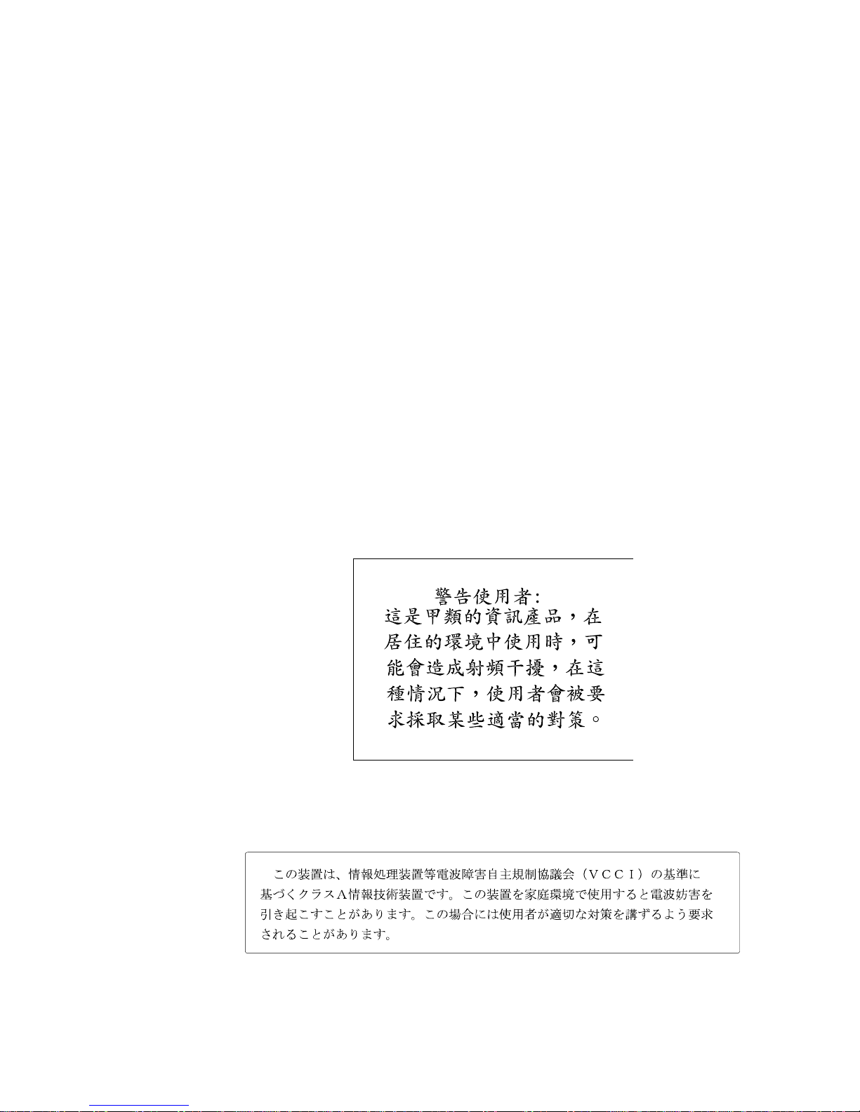
66 IBM® xSeries 250: Ins ta llation Guide
United Kingdom telecommunications safety
requirement
Notice to Customers
This apparatus is approved under approval number NS/G/1234/J/100003 for
indirect connection to public telecommunication systems in the United Kingdom.
European Union EMC Directive conformance statement
This product is in conformity with the protection requirements of EU Council
Directive 89/336/EEC on the approximation of the laws of the Member States r elating
to electromagnetic compatibility. IBM cannot accept responsibility for any fail ure to
satisfy the protection requirements r esulting from a nonrecommended modification of
the product, including the fitting of non-IBM option cards.
This product has been tested and found to comply with the limits for Class A
Information Technology Equipment according to CISPR 22/European Standard EN
55022. The Limits for Class A equipment were derived for commercial and industrial
environments to provide reasonable protection against interference with licensed
communication equipment.
Attention: This is a Class A product. In a domestic environment this product may
cause radio interference in which case the user may be required to take adequate
measures.
Taiwan electrical emission statement
Japanese Voluntary Control Council for Interference
(VCCI) statement
Page 79

Appendix A. Product warranties and notices 67
Power cords
For your safety, IBM provides a power cord with a grounded attachment plug to use
with this IBM product. T o avoid electrical shock, always use the power cord and plug
with a properly grounded outlet.
IBM power cords used in the United States and Canada are listed by Underwriter’s
Laboratories (UL) and certified by the Canadian Standards Association (CSA).
For units intended to be operated at 115 volts: Use a UL-listed and CSA-certified cord
set consisting of a minimum 18 AWG, Type SVT or SJT, three-conductor cord, a
maximum of 15 feet in length and a parallel blade, grounding-type attachment plug
rated 15 amperes, 125 volts.
For units intended to be operated at 230 volts (U.S. use): Use a UL-listed and CSAcertified cord set consisting of a minimum 18 AWG, Type SVT or SJT, three-co nductor
cord, a maximum of 15 feet in length and a tandem blade, grounding-type attachment
plug rated 15 amperes, 250 volts.
For units intended to be operated at 230 volts (outside the U.S.): Use a cord set with a
grounding-type attachment plug. The cord set should have the appropriate safety
approvals for the country in which the equipment will be installed.
IBM power cords for a specific country or region are usually available only in that
country or region.
IBM power cord part
number
Used in these countries and regions
13F9940 Argentina, Australia, China (PRC), New Zealand, Papua New
Guinea, Paraguay, Uruguay, Western Samoa
13F9979 Afghanistan, Algeria, Andorra, Angola, Austria, Belgium, Benin,
Bulgaria, Burkina Faso, Burundi, Cameroon, Central African Rep.,
Chad, China (Macau S.A.R.), Czech Republic, Egypt, Finland,
France, French Guiana, Germany, Greece, Guinea, Hungary,
Iceland, Indonesia, Iran, Ivory Coast, Jordan, Lebanon,
Luxembourg, Malagasy, Mali, Martinique, Mauritania, Mauritius,
Monaco, Morocco, Mozambique, Netherlands, New Caledonia,
Niger, Norway, Poland, Portugal, Romania, Senegal, Slovakia,
Spain, Sudan, Sweden, Syria, Togo, Tunisia, Turkey, former USSR,
Vietnam, former Yugoslavia, Zaire, Zimbabwe
13F9997 Denmark
14F0015 Bangladesh, Burma, Pakistan, South Africa, Sri Lanka
14F0033 Antigua, Bahrain, Brunei, Channel Islands, China (Hong Kong
S.A.R.), Cyprus, Dubai, Fiji, Ghana, India, Iraq, Ireland, Kenya,
Kuwait, Malawi, Malay sia, Malt a, Nepal, N igeria , Polyn esia, Qatar,
Sierra Leone, Singapore, Tanzania, Uganda, United Kingdom,
Yemen, Zambia
14F0051 Liechtenstein, Switzerland
14F0069 Chile, Ethiopia, Italy, Libya, Somalia
14F0087 Israel
1838574 Thailand
Page 80

68 IBM® xSeries 250: Ins ta llation Guide
6952301 Bahamas, Barbados, Bermuda, Bolivia, Brazil, Canada, Cayman
Islands, Colombia, Costa Rica, Dominican Republic, Ecuador, El
Salvador, Guatemala, Guyana, Haiti, Honduras, Jamaica, Japan,
Korea (South), Liberia, Mexico, Netherlands Antilles, Nicaragua,
Panama, Peru, Philippines, Saudi Arabia, Suriname, Taiwan,
Trinidad (West Indi es), United States of America, Venezu ela
IBM power cord part
number
Used in these countries and regions
Page 81

© Copyright IBM Corp. 2001 69
Index
A
AC power 39
acoustical noise emissions 2
activity lights
CD-ROM drive 41
diskette drive 41
processor 43
adapters
considerations 11, 13
hot-plug devices 12
installing
hot-plug 12
non-hot-plug 14
slot locations 11
system requirements 11
B
backplane, hot-swap drive
connectors 25
installing 29
removing 26
using 24
beep codes 47
C
cable
SCSI 19, 29
cabling
options 24, 25
SCSI backplane 24
ServeRAID adapter 16
CD-ROM drive
activity light 41
eject button 41
specifications 2
Class A electronic emission notice
65
components
color
4, 7
major 4
SCSI backplane 25
Configuration/Setup Utility pro-
gram 45
configuring your server 45
connecting
See also installing
repeater card to SCSI backplane
27
shuttle 30
connectors
hot-swap drive backplane 25
memory module 22
SCSI repeater card 25
controls and indicators 41
cover
removing 9
replacing 37
D
depth 2
DIMMs
installation order 22
installing 23
disconnecting
See also removing
shuttle 26
diskette
eject button 41
diskette drive
activity light 41
specifications 2
documentation CD 1
drive
bays 24
hot-swap 31
placement guide 32
E
eject button
CD-ROM
41
diskette 41
electrical input 2
electronic emission Class A notice
65
electrostatic discharge-sensitive de-
vices, handling 8, 12, 14
environment 2
environmental specification s
dimensions 2
error messages
POST 48
Ethernet speed 100 Mbps light 43
Ethernet transmit/receive activity
light 43
Ethernet-link status light 43
F
FCC Class A notice 65
features
LVD SCSI backplane 24
server 2
filler panel
hot-swap drive 31
power supply 34
H
hard-disk drive activity light 41, 43
hard-disk drive status light 41
heat output 2
hot-swap and hot-plug devices
adapters 12
color 4, 7
hard disk drives 31
power supplies 35
hot-swap drive
backplane
components 25
installing 29
removing 26
using 24
installing 31
specifications 2
hot-swap power supply
installing 35
I
important notes 64
indicators
See lights
information LED pane l 42
informatio n light 43
installation order
memory modules 22
installing
hot-plug adapter 12
hot-swap drive 31
hot-swap drive backplane 29
hot-swap power supply 35
media-bay bezel 36
memory module 23
microprocessor 33
non-hot-plug adapter 14
non-hot-swap drive 31
options
major components 4
system requirements 7
SCSI repeater ca rd 25
VRM 33
L
LEDs
See also lights
front of server 43
hard disk drive 43
lights
CD-ROM drive activity 41
diskette drive activity 41
Ethernet speed 100 Mbps 43
Ethernet transmit/receive 43
Ethernet-link status 43
hard-disk drive activity 41, 43
hard-disk drive status 41
information 43
POST-complete 43
processor activity 43
system error 43
system power 43
LVD SCSI backplane 24, 25, 29
M
major components 4
media-bay bezel
installing 36
removing 10
memory
connectors 22
installation order 22
installing 22
specifications 2
microprocessor
activity lights 43
installing 33
location 33
specifications 2
VRM 33
N
non-hot-swap drive
Page 82

70 IBM® xSeries 250: Ins ta llation Guide
installing 31
specifications 2
NOS See operating system
O
operating system, installing 45
options
internal
cabling 24, 25
P
PCI expansion slots 2, 11, 13
POST error messages 48
POST-complete light 43
power cords 35, 67
power supply
installing 35
operating requirements 34
specifications 2
power-control button 41
power-control button shield 39
problems, solving 47
processor activity lights 43
R
removing
cover 9
hot-swap drive backplane 26
media-bay bezel 10
repeater card
connectors 25
installing 25
replacing
cover 37
reset button 41
S
safety information
book
v
electrical vii
laser viii
lifting ix
power cord 35
statements v
SCSI
backplane
components 25
installing 25, 29
removing 26
using 24
cable
repeater card 29
ServeRAID adapter 19
IDs
assigning 32
repeater card
connectors 25
installing 25
SCSISelect Utility program 45
ServeRAID adapter 16
ServeRAID Configuration program
45
ServerGuide
CDs 45
error symptoms 50
shield
power-control button 39
shutting down the server 40
shuttle
connecting 30
disconnecting 26
size 2
solving problems 47
specifications 2
starting the server 39
static-sensitive devices, handling 8
stopping the server 40
system error light 43
system power light 43
system reliability 7
T
trademarks 64
troubleshooting chart 51
turning off the server 40
turning on the server 39
U
United States electronic emission
Class A notice 65
United States FCC Class A notice 65
V
video
specifications 2
voltage regulator module
installing 33
location 33
VRM See voltage regulator module
W
Web site 1
weight 2
working inside server with power
on 8
Page 83

Page 84

IBM
Part Number: 21P9019
Printed in the United States of America.
21P919
 Loading...