

Page 1

®
xSeries 240
User’s Reference
Page 2

Note
Before using this information and the product it supports, be sure to read the general information in Appendix B,
“Product warranties and notices” on page 179.
First Edition (October 2000)
Copyright International Business Machines Corporation 2000. All rights reserved.
Note to U.S. Government Users — Documentation related to restricted rights — Use, duplication or disclosure is subject to
restrictions set forth in GSA ADP Schedule Contract with IBM Corp.
Page 3

Contents
Safety information statements ............................ v
Lithium battery notice ................................. vii
Laser compliance statements ............................. viii
About this book ..................................... ix
How this book is organized ............................... ix
Notices used in this book ................................ x
Chapter 1. Introducing the IBM xSeries 240 ................... 1
Features and specifications ............................... 2
What your server offers ................................. 4
Reliability, availability, and serviceability features .................. 6
Controls and indicators ................................. 7
Operator information panel .............................. 10
Input/output connectors and expansion slots .................... 11
Power supplies . . . . . . . . . . . . . . . . . . . . . . . . . . . . . . . . . . . . . 13
Chapter 2. Arranging your workspace ...................... 17
Comfort . . . . . . . . . . . . . . . . . . . . . . . . . . . . . . . . . . . . . . . . . 17
Glare and lighting .................................... 17
Air circulation . . . . . . . . . . . . . . . . . . . . . . . . . . . . . . . . . . . . . . 18
Electrical outlets and cable lengths ......................... 18
Chapter 3. Configuring your server ....................... 19
Configuration overview . . . . . . . . . . . . . . . . . . . . . . . . . . . . . . . . . 19
The Configuration/Setup Utility program ....................... 20
Using the Configuration/Setup Utility main menu .................. 21
Configuring options . . . . . . . . . . . . . . . . . . . . . . . . . . . . . . . . . . . 30
Resolving configuration conflicts ........................... 30
Using the SCSISelect utility program ........................ 32
Configuring the Ethernet controller .......................... 35
Failover for redundant Ethernet ............................ 35
Chapter 4. Installing options . . . . . . . . . . . . . . . . . . . . . . . . . . . . 41
Before you begin .................................... 41
Electrical safety . . . . . . . . . . . . . . . . . . . . . . . . . . . . . . . . . . . . . 42
Working inside the server with power on ...................... 44
Handling static-sensitive devices ........................... 44
System reliability considerations ........................... 45
Preparing to install options .............................. 46
Working with adapters ................................. 53
Installing a microprocessor kit ............................ 62
Installing memory-module kits ............................ 65
Installing internal drives ................................ 67
Installing a hot-swap power supply .......................... 79
Removing a hot-swap power supply ......................... 81
Replacing a hot-swap fan assembly ......................... 83
Completing the installation .............................. 85
Connecting external options .............................. 90
Copyright IBM Corp. 2000 iii
Page 4

Chapter 5. System board and processor board ................ 99
System-board component locations
System-board jumpers . . . . . . . . . . . . . . . . . . . . . . . . . . . . . . . . 100
Processor-board component locations
Processor-board jumper and switches
Changing jumper positions ............................. 103
Chapter 6. Solving problems . . . . . . . . . . . . . . . . . . . . . . . . . . 107
Diagnostic tools overview .............................. 107
Diagnostic programs . . . . . . . . . . . . . . . . . . . . . . . . . . . . . . . . . 110
Power-on self-test (POST) messages ....................... 112
Power-on self test (POST) beep codes ...................... 122
Recovering BIOS . . . . . . . . . . . . . . . . . . . . . . . . . . . . . . . . . . . 124
Diagnostic error message tables .......................... 125
Ethernet controller messages ............................ 136
Troubleshooting . . . . . . . . . . . . . . . . . . . . . . . . . . . . . . . . . . . . 143
Resolving configuration conflicts
Identifying problems using status LEDs
Replacing the battery ................................ 157
......................... 99
....................... 101
....................... 102
.......................... 151
...................... 151
Chapter 7. Getting help, service, and information .............. 161
Service support . . . . . . . . . . . . . . . . . . . . . . . . . . . . . . . . . . . . 162
Before you call for service .............................. 163
Getting customer support and service ....................... 163
Purchasing additional services ........................... 166
Ordering publications . . . . . . . . . . . . . . . . . . . . . . . . . . . . . . . . 169
Appendix A. Installing a server in a rack enclosure ............ 171
Appendix B. Product warranties and notices ................ 179
Warranty Statements . . . . . . . . . . . . . . . . . . . . . . . . . . . . . . . . . 179
Notices . . . . . . . . . . . . . . . . . . . . . . . . . . . . . . . . . . . . . . . . . 188
Electronic emission notices ............................. 191
Index . . . . . . . . . . . . . . . . . . . . . . . . . . . . . . . . . . . . . . . . . . 193
iv IBM xSeries User's Reference
Page 5
Safety information statements
Before installing this product, read the Safety Information.
Antes de instalar este produto, leia as Informações de Segurança.
Před instalací tohoto produktu si přečtěte příručku bezpečnostních instrukcí.
Læs sikkerhedsforskrifterne, før du installerer dette produkt.
Ennen kuin asennat tämän tuotteen, lue turvaohjeet kohdasta Safety Information.
Avant d'installer ce produit, lisez les consignes de sécurité.
Vor der Installation dieses Produkts die Sicherheitshinweise lesen.
Prima di installare questo prodotto, leggere le Informazioni sulla Sicurezza
Lees voordat u dit product installeert eerst de veiligheidsvoorschriften.
Les sikkerhetsinformasjonen (Safety Information) før du installerer dette produktet.
Antes de instalar este produto, leia as Informações sobre Segurança.
Pred inštaláciou tohto zariadenia si pečítaje Bezpečnostné predpisy.
Antes de instalar este producto lea la información de seguridad.
Läs säkerhetsinformationen innan du installerar den här produkten.
Copyright IBM Corp. 2000 v
Page 6

1
DANGER
Electrical current from power, telephone, and communication
cables is hazardous.
To avoid a shock hazard:
– Do not connect or disconnect any cables or perform
installation, maintenance, or reconfiguration of this product
during an electrical storm.
– Connect all power cords to a properly wired and grounded
electrical outlet.
– Connect to properly wired outlets any equipment that will be
attached to this product.
– When possible, use one hand only to connect or disconnect
signal cables.
– Never turn on any equipment when there is evidence of fire,
water, or structural damage.
– Disconnect the attached power cords, telecommunications
systems, networks, and modems before you open the
device covers, unless instructed otherwise in the installation
and configuration procedures.
– Connect and disconnect cables as described in the
following table when installing, moving, or opening covers
on this product or attached devices.
To Connect:
1. Turn everything OFF.
2. First, attach all cables to devices.
3. Attach signal cables to connectors.
4. Attach power cords to outlet.
5. Turn device ON.
To Disconnect:
1. Turn everything OFF.
2. First, remove power cords from outlet.
3. Remove signal cables from connectors.
4. Remove all cables from devices.
vi IBM xSeries User's Reference
Page 7

Lithium battery notice
2
CAUTION:
When replacing the lithium battery, use only IBM Part Number 33F8354
or an equivalent type battery recommended by the manufacturer. If
your system has a module containing a lithium battery, replace it only
with the same module type made by the same manufacturer. The
battery contains lithium and can explode if not properly used, handled,
or disposed of.
Do not:
– Throw or immerse into water
– Heat to more than 100°C (212°F)
– Repair or disassemble
Dispose of the battery as required by local ordinances or regulations.
Safety information statements vii
Page 8

Laser compliance statements
Some server models are equipped from the factory with a CD-ROM drive.
CD-ROM drives are also sold separately as options. The CD-ROM drive is a laser
product. The CD-ROM drive is certified in the U.S. to conform to the requirements
of the Department of Health and Human Services 21 Code of Federal Regulations
(DHHS 21 CFR) Subchapter J for Class 1 laser products. Elsewhere, the drive is
certified to conform to the requirements of the International Electrotechnical
Commission (IEC) 825 and CENELEC EN 60 825 for Class 1 laser products.
3
CAUTION:
When laser products (such as CD-ROMs, DVD drives, fiber optic
devices, or transmitters) are installed, note the following:
– Do not remove the covers. Removing the covers of the laser
product could result in exposure to hazardous laser radiation.
There are no serviceable parts inside the device.
– Use of controls or adjustments or performance of procedures other
than those specified herein might result in hazardous radiation
exposure.
DANGER
Some laser products contain an embedded Class 3A or Class 3B
laser diode. Note the following.
Laser radiation when open. Do not stare into the beam, do not
view directly with optical instruments, and avoid direct exposure
to the beam.
viii IBM xSeries User's Reference
Page 9

About this book
This book provides instructions for installing and removing server options and
configuring and troubleshooting your server. It also provides information to help
you solve problems if they occur.
How this book is organized
Chapter 1, “Introducing the IBM xSeries 240,” describes the xSeries 240 server
and provides an overview of the server's features.
Chapter 2, “Arranging your workspace,” provides information on arranging your
equipment and workspace.
Chapter 3, “Configuring your server,” describes how to use the Configuration/Setup
Utility program to configure your server. This chapter also provides instructions for
using various utility programs.
Chapter 4, “Installing options,” contains instructions for installing and removing
options, such as memory, adapters, and internal drives. Instructions for connecting
external options are also included in this chapter.
Chapter 5, “System board and processor board,” contains information about the
system board and processor board component, switch, and jumper locations. This
chapter also provides the instructions needed to change the jumper settings.
Chapter 6, “Solving problems,” includes an overview of the diagnostic tools,
instructions for testing the server, lists of error messages, and troubleshooting
charts.
Chapter 7, “Getting help, service, and information,” provides the telephone number
and World Wide Web listings that you can use to obtain product updates, help, or
service.
Appendix A, “Installing a server in a rack enclosure,” contains information about
installing rack models of the xSeries 240.
Appendix B, “Product warranties and notices,” contains warranty and emission
notices. This chapter also contains trademarks and general-information notices.
An index follows the appendix.
Copyright IBM Corp. 2000 ix
Page 10

Notices used in this book
This book contains information notices that relate to a specific topic. The Caution
and Danger notices also appear in the multilingual Safety Information book
provided on the IBM xSeries Documentation CD. Each notice is numbered for easy
reference to the corresponding notices in the multilingual book. The notice
definitions are as follows:
Notes
These notices provide important tips, guidance, or advice.
Attention
These notices indicate possible damage to programs, devices, or data. An
attention notice is placed just before the instruction or situation in which
damage could occur.
Caution
These notices indicate situations that can be potentially hazardous to you. A
caution notice is placed just before a description of a potentially hazardous
procedure step or situation.
Danger
These notices indicate situations that can be potentially lethal or extremely
hazardous to you. A danger notice is placed just before a description of a
potentially lethal or extremely hazardous procedure step or situation.
x IBM xSeries User's Reference
Page 11

Chapter 1. Introducing the IBM xSeries 240
Your IBM xSeries 240 is a high-performance, symmetric multiprocessing
(SMP) server. It is ideally suited for networking environments that require superior
microprocessor performance, efficient memory management, flexibility, and large
amounts of reliable data storage.
Performance, ease of use, reliability, and expansion capabilities were key
considerations during the design of your server. These design features make it
possible for you to customize the system hardware to meet your needs today, while
providing flexible expansion capabilities for the future.
Your server comes with a three-year limited warranty and IBM Server Start Up
Support. You can obtain up-to-date information about your xSeries 240 server and
other IBM server products at http://www.ibm.com/eserver/xseries on the World Wide
Web.
Your server serial number and model number are located on labels on the rear of
the server and on the front under the trim bezel. Write these numbers in the
spaces provided in your Installation Guide. You will need these numbers when you
register your server with IBM. After you register your server, you can receive
information about updates, performance tips, and compatibility. To register your
server, go to http://www.ibm.com/pc/register on the World Wide Web.
4
18 kg (37 lbs)
CAUTION:
Use safe practices when lifting.
32 kg (70.5 lbs) 55 kg (121.2 lbs)
Copyright IBM Corp. 2000
1
Page 12

Features and specifications
The following table summarizes the features of the xSeries 240 server.
Microprocessor
Intel
32 KB of level-1 cache
256 KB of level-2 cache (min.)
Expandable to two microprocessors
Memory
Standard: 128 MB (min), expandable
133 MHz, registered, error correcting
Four dual inline memory-module
Diskette Drive
Standard: One 3.5-inch, 1.44 MB
Hard Disk Drives
Up to six hot-swappable hard disk
CD-ROM Drive
Standard: 40X IDE
Keyboard and Auxiliary Device
(standard only on tower models)
Keyboard
Mouse
Expansion Bays
Six slim (1-inch) or three half-high
Three 5.25-inch non-hot-swap bays
Pentium III microprocessor
with MMX technology and SIMD
extensions
to 4 GB
code (ECC), synchronous dynamic
random access memory (SDRAM)
(complying with PC 133 SDRAM
Registered DIMM Specification,
Revision 1.0 or later). When installed
in systems using 100 MHz front-side
bus microprocessors, the memory
operates at 100 MHz.
(DIMM) sockets
drives supported
(1.6-inch) hot-swap drive bays
(one contains the CD-ROM drive)
Table 1. Server features
Expansion Slots
Up to five PCI adapters supported.
Three 64-bit hot-plug PCI slots
Two standard (non-hot-plug) 32-bit
PCI slots
Upgradable Microcode
BIOS, diagnostics, and Advanced
System Management Processor
upgrades (when available) can
update EEPROMs on the system
board
Security Features
Door and side cover lock (tower
model only)
Power-on and administrator
passwords
Selectable drive-startup
Keyboard password
System management security
– User log-in password
– Read-only or read/write access
– Dial back
Predictive Failure Analysis (PFA)
Alerts
Power supplies
Fans
Memory
Hard disk drives
Microprocessors
Voltage regulator modules (VRMs)
Integrated Functions
Two serial ports
Two universal serial bus (USB) ports
One parallel port
Mouse port
Keyboard port
Video port
Advanced System Management
Interconnect port
Two SCSI ports (one internal, one
external)
10BASE-T/100BASE-TX Ethernet port
(controller on system board)
Redundant Ethernet capability,
through the use of an optional
network interface card (NIC)
Advanced System Management
Processor on system board
Dedicated Advanced System
Management I/O port
Video controller (with 4MB video
memory) compatible with:
– Super video graphics array
(SVGA)
– Video graphics adapter (VGA)
Power Supply
Two 250 W (115–230 V ac)
– Standard - 500 W non-redundant,
250 W redundant
– Optional - Additional 250 W
power supply is available for
500 W redundancy
Automatic voltage range selection
Built-in overload and surge protection
Automatic restart after a loss of
power
Redundant Cooling
Three hot-swap fans
2 IBM xSeries User's Reference
Page 13

The following table provides the specifications for the xSeries 240 server.
Size (Tower Model)
– Depth: 659.3 mm (26 in.)
– Height: 426.5 mm (16.8 in.)
– Width: 217.3 mm (8.6 in.)
Size (Rack Model)
– Depth: 629.3 mm (24.8 in.)
– Height: 217.3 mm (8.6 in.)
(5 U)
– Width: 426.6 mm (16.8 in.)
Weight (Tower Model)
Minimum configuration: 26.6 kg
(58.6 lb)
Maximum configuration: 37.5 kg
(82.7 lb)
Weight (Rack Model)
Minimum configuration: 25.3 kg
(55.8 lb)
Maximum configuration: 36.2 kg
(79.8 lb)
Heat Output
Approximate heat output in British
Thermal Units (Btu) per hour:
– Minimum configuration:
683 Btu (200 watts)
– Maximum configuration:
2048 Btu (600 watts)
Table 2. Server specifications
Electrical Input
Sine-wave input (50 to 60 Hz) is
required
Input voltage:
– Low range:
- Minimum: 90 V ac
- Maximum: 137 V ac
– High range:
- Minimum: 180 V ac
- Maximum: 265 V ac
– Input kilovolt-amperes (kVA)
approximately:
- Minimum configuration as
shipped: 0.08 kVA
- Maximum configuration:
0.52 kVA
Power Available for Drives
Each hot-swap drive bay:
– +5 V dc line: 15 A
– +12 V dc line: 17.2 A
Acoustical Noise Emissions Values
Sound power, idling: 6.6 bel
maximum
Sound power, operating: 6.8 bel
maximum
Sound pressure, operating: 67 dBa
maximum
Environment
Air temperature:
– Server on: 10° to 35° C
(50° to 95° F)
Altitude: 0 to 914 m (3000 ft.)
– Server on: 10° to 32° C
(50° to 90° F)
Altitude: 914 m (3000 ft.) to
2133 m (7000 ft.)
– Server off: 10° to 43° C
(50° to 110° F)
Maximum Altitude: 2133 m
(7000 ft.)
Humidity:
– Server on: 8% to 80%
– Server off: 8% to 80%
Maximum altitude: 2133 m
(7000 ft)
Chapter 1. Introducing the IBM xSeries 240 3
Page 14

What your server offers
The unique design of your IBM xSeries 240 takes advantage of advancements in
symmetric multiprocessing (SMP), data storage, and memory management. Your
server combines:
Impressive performance using an innovative approach to SMP
Your server supports up to two Pentium III microprocessors. Your server
comes with one microprocessor installed; you can install an additional
microprocessor to enhance performance and provide SMP capability.
Large data-storage and hot-swap capabilities
All models of the server support up to six hot-swap hard disk drives. This
hot-swap feature enables you to remove and replace hard disk drives without
turning off the server.
Hot-plug PCI adapter capabilities
Your server has three hot-plug slots for PCI adapters. This feature is
sometimes referred to as Active PCI. With operating system support, you can
replace failing hot-plug PCI adapters without turning off the server. If the
hot-add feature is supported by your operating system and the PCI adapter,
you can also add PCI adapters in these slots without turning off the server.
Redundant cooling and power capabilities
The redundant cooling and hot-swap capabilities of the fans in your server
allow continued operation if one of the fans fails. You can also replace a failing
fan without turning off the server.
The two 250-watt power supplies in your server provide redundant power for
many configurations of your server. If the average load on your server is less
than 250 watts and a problem occurs with one of the power supplies, the other
power supply can handle the load. For power loads above 250 watts, you can
install a third, optional power supply to provide a full 500 watts of power. The
NON REDUNDANT light emitting diode (LED) on the diagnostic LED panel is lit
when the power load is 250 watts or greater with two power supplies installed.
Large system memory
The memory bus in your server supports up to 4GB of system memory. The
memory controller provides error correcting code (ECC) support for up to four
industry-standard PC133, 3.3 V, 168-pin, 8-byte, registered,
synchronous-dynamic-random access memory (SDRAM) DIMMs (Intel
PC-Registered SDIMM Specifications, Revision 1.0 or later), synchronous, dual
inline memory modules.
4 IBM xSeries User's Reference
Page 15

System-management capabilities
Your server comes with an Advanced System Management Processor on the
system board. This processor, in conjunction with the systems-management
software provided with your server, allows you to manage the functions of the
server locally and remotely. The Advanced System Management Processor
also provides system monitoring, event recording, and dial-out alert capability.
Note: The Advanced System Management Processor is sometimes referred to
as the service processor.
Refer to the information provided with the systems-management software for
more information.
Integrated network environment support
Your server comes with an Ethernet controller on the system board. This
Ethernet controller has an interface for connecting to 10-Mbps or 100-Mbps
networks. The server automatically selects between 10BASE-T and
100BASE-TX. The controller provides full-duplex (FDX) capability, which allows
simultaneous transmission and reception of data on the Ethernet local area
network (LAN).
Redundant network-interface card
The addition of an optional, redundant network interface card (NIC) provides a
failover capability to a redundant Ethernet connection. If a problem occurs with
the primary Ethernet connection, all Ethernet traffic associated with this primary
connection is automatically switched to the redundant NIC. This switching
occurs without data loss and without user intervention.
IBM ServerGuide CDs
The ServerGuide
CDs included with your server provide programs to help you
set up your server and install the network operating system (NOS). The
ServerGuide program detects the hardware options installed and provides the
correct configuration program and device drivers. For more information, see
the ServerGuide topic provided on the IBM xSeries Documentation CD.
Your server is designed to be cost-effective, powerful, and flexible. It uses
peripheral component interconnect (PCI) bus architecture to provide compatibility
with a wide range of existing hardware devices and software applications.
As always, your IBM server meets stringent worldwide certifications for power,
electromagnetic compatibility (EMC), and safety.
Chapter 1. Introducing the IBM xSeries 240 5
Page 16

Reliability, availability, and serviceability features
Three of the most important features in server design are reliability, availability, and
serviceability (RAS). These factors help to ensure the integrity of the data stored
on your server; that your server is available when you want to use it; and that
should a failure occur, you can easily diagnose and repair the failure with minimal
inconvenience.
The following is an abbreviated list of the RAS features that your server supports.
Menu-driven setup, system configuration, RAID configuration, and diagnostic
programs
Power-on self-test (POST)
Integrated Advanced System Management Processor
Predictive failure alerts
System auto-configuring from configuration menu
Remote system problem-determination support
Power and temperature monitoring
Fault-resilient startup
Hot-swap drive bays
Support for hot-plug PCI adapters
Error codes and messages
System error logging
Upgradable BIOS, diagnostics, and Advanced System Management Processor
code
Automatic restart after a power failure
Parity checking on the SCSI and PCI buses
Error checking and correcting (ECC) memory
Redundant hot-swap power supply option
Redundant hot-swap cooling
Redundant Ethernet capabilities (with optional adapter)
Vital Product Data (VPD) on processor complex, system board, power
backplane, SCSI backplane, and each power supply.
Operator information and diagnostic LED panels
Customer support center 24 hours per day 7 days a week
Remote Connect
Light Path Diagnostics
1
1
Service availability will vary by country. Response time will vary depending on the number and nature of incoming calls.
6 IBM xSeries User's Reference
Page 17

Controls and indicators
The most commonly used controls and indicators on the front of the server appear
in the following illustrations.
Tower model
Rack model
Chapter 1. Introducing the IBM xSeries 240 7
Page 18

1 Operator Information Panel: The lights on this panel provide status
information for your server. See “Operator information panel” on page 10 for
more information.
2 Diskette-Eject Button: Press this button to eject a diskette from the drive.
3 Diskette Drive In-Use Light: When this light is on, the diskette drive is being
accessed.
4 CD-ROM Eject/Load Button: Press this button to eject or retract the
CD-ROM tray so that you can insert or remove a CD.
5 Hard Disk Status Light: Each of the hot-swap drive bays has a Hard Disk
Status light. When this amber light is on continuously, the drive has failed.
When the light flashes slowly (one flash per second), the drive is being rebuilt.
When the light flashes rapidly (three flashes per second), the controller is
identifying the drive.
6 Hard Disk Activity Light: Each of the hot-swap drive bays has a Hard Disk
Activity light. When this green light is flashing, the drive is being accessed.
7 Cover Release Lever: Use this lever to release the left-side cover on the
tower model or the top cover on the rack model.
8 Reset Button: Press this button to reset the server and run the power-on
self-test (POST).
9 Power Control Button: Press this button to manually turn the server on or
off. (See “Turning on the server” on page 9 and “Turning off the server” on
page 9 for more information.)
1 CD-ROM Drive In-Use Light: When this light is on, the CD-ROM drive is
being accessed.
11 CD-ROM Manual Tray-Release Opening: Insert a straightened paper clip in
the opening to release the CD-ROM tray when using the CD-ROM eject
button is not successful.
8 IBM xSeries User's Reference
Page 19

Turning on the server
Use the following instructions to turn on the server.
You can turn on the server by pressing the Power Control button on the front of
the server.
Note: If you have just plugged the power cord of your server into an electrical
If the server is turned on and a power failure occurs, the server will start
automatically when power is restored.
The Advanced System Management Processor can also turn on the server.
Turning off the server
Use the following instructions to turn off the server.
5
outlet, wait approximately 20 seconds before pressing the Power
Control button.
CAUTION:
The power control button on the device and the power switch on the
power supply do not turn off the electrical current supplied to the
device. The device also might have more than one power cord. To
remove all electrical current from the device, ensure that all power
cords are disconnected from the power source.
2
1
You can turn off the server by pressing the Power Control button on the front of
the server. Pressing the Power Control button starts an orderly shutdown of
the operating system, if this feature is supported by your operating system, and
places the server in standby mode.
Note: After turning off the server, wait at least 5 seconds before pressing the
Power Control button to power the server on again.
You can press and hold the Power Control button for more than 4 seconds to
cause an immediate shutdown of the server and place the server in standby
mode. This feature can be used if the operating system halts.
You can disconnect the server power cords from the electrical outlets to shut
off all power to the server.
Note: Wait about 15 seconds after disconnecting the power cords for your
Chapter 1. Introducing the IBM xSeries 240
system to stop running. Watch for the System Power light on the
operator information panel to stop blinking.
9
Page 20

Operator information panel
The operator information panel on the front of the server contains status lights.
OK
LINK
100
OK
MB
1 System Power Light: When this green light is on, system power is present
in the server. When this light flashes, the server is in standby mode (the
system power supply is turned off and ac current is present). When this light
is off, either a power supply, ac power, or a light has failed.
Attention: If this light is off, it does not mean there is no electrical current
present in the server. The light might be burned out. To remove all electrical
current from the server, you must unplug the server power cords from the
electrical outlets.
2 System POST Complete Light: This green light is on when the power-on
self-test (POST) completes without any errors.
3 SCSI Hard Disk Drive Activity Light: This green light is on when there is
activity on a hard disk drive.
4 Processor 1 Activity Light: This green light is on when there is
microprocessor 1 activity.
1 2
TX
RX
5 Processor 2 Activity Light: This green light is on when there is
microprocessor 2 activity.
6 Information Light: This amber light is on when the information log contains
information about certain conditions in your server that might affect
performance. For example, the light will be on if your server does not have
redundant power. A light on the diagnostic LED panel will also be on. (For
more information, see “Identifying problems using status LEDs” on page 151.)
7 System Error Light: This amber light is on when a system error occurs. A
light on the diagnostic LED panel will also be on to further isolate the error.
(For more information, see “Identifying problems using status LEDs” on
page 151.)
8 Ethernet Transmit/Receive Activity Light: When this green light is on,
there is transmit or receive activity to or from the server.
9 Ethernet Link Status Light: When this green light is on, there is an active
connection on the Ethernet port.
1 Ethernet Speed 100 Mbps Light: When this green light is on, the Ethernet
speed is 100 Mbps. When the light is off, the Ethernet speed is 10 Mbps.
10 IBM xSeries User's Reference
Page 21

Input/output connectors and expansion slots
The following illustrations show the expansion slots and the input/output connectors
(ports) on the rear of the server.
Tower model
Rack model
DC
AC
AC
DC
DC
AC
1 Advanced System Management Interconnect Knockout: Your server has
an external connector knockout for the Advanced System Management
Interconnect option. This option allows you to connect rack or multirack
systems through a daisy-chain cable in half-duplex mode.
2 External Connector Knockout: Your server has an external connector
knockout that can be used when you install options.
3 PCI Expansion Slots: Your server has five available peripheral component
interconnect (PCI) expansion slots. Three of the PCI slots support hot-plug
PCI (sometimes referred to as Active PCI) adapters.
Many adapters provide bus-master capabilities, which enable the adapters to
perform operations without interrupting the system microprocessors.
Chapter 1. Introducing the IBM xSeries 240 11
AC
DC
Page 22

4 Serial A Connector: A serial signal cable for a modem or other serial device
connects to this 9-pin serial connector. Serial port A can be shared by the
Advanced System Management Processor and the operating system. See
“Devices and I/O Ports” on page 22 for port assignment information. If you
are using a 25-pin signal cable, you need a 9-pin-to-25-pin adapter cable.
5 Serial B Connector: A serial signal cable for a modem or other serial device
connects to this 9-pin serial connector. Serial port B is used by the operating
system and cannot be shared by the Advanced System Management
Processor. See “Devices and I/O Ports” on page 22 for port assignment
information. If you are using a 25-pin signal cable, you need a 9-pin-to-25-pin
adapter cable.
6 Hot-Plug PCI Expansion Slots: Your server has three hot-plug PCI
expansion slots.
7 Attention Lights for Hot-Plug PCI Slots: Each hot-plug PCI slot has an
Attention light that is visible from the rear of the server. An Attention light
flashes approximately once per second when it is on. The meaning of the
Attention lights is defined by your operating system. Refer to your operating
system documentation to determine if it supports hot-plug PCI adapters and, if
so, what the Attention lights indicate.
8 Non-Hot-Plug PCI Expansion Slots: Your server has two non-hot-plug PCI
expansion slots.
9 Parallel Connector: A signal cable for a parallel device, such as a printer,
connects here.
1 SCSI Connector: External SCSI devices attach here. For more information,
see “Connecting external options” on page 90.
11 Management Port C Connector: This connector is used to attach a modem
that is dedicated to communication with the Advanced System Management
Processor.
12 Video Connector: The monitor signal cable connects here.
13 Universal Serial Bus 1 and 2 Connectors: You can attach an I/O device to
either of these Universal Serial Bus (USB) connectors. USB 2 is the
connector nearest to the edge of the server. You need a 4-pin cable to
connect a device to USB 1 or 2.
Note: If a standard (non-USB) keyboard is attached to the keyboard port, the
USB ports are disabled while the power-on self-test (POST) is
running, and no USB devices will work during POST.
14 Ethernet Connector: Your server has one RJ-45 Ethernet connector. This
connector is for attaching the network cable to the integrated 10BASE-T or
100BASE-TX, twisted-pair transceiver.
15 Mouse Connector: The mouse cable connects here. This port sometimes is
called an auxiliary-device or pointing-device port.
16 Keyboard Connector: The keyboard cable connects here.
17 Power Connectors: The power cords for the power supplies connect here.
Note: For pin assignments and other details about these connectors, see
“Connecting external options” on page 90.
12 IBM xSeries User's Reference
Page 23

Power supplies
The following illustrations show the power supplies and power lights on your server.
Your server comes with two hot-swap power supplies installed. You can install a
third power supply. (See “Installing a hot-swap power supply” on page 79 for
instructions about installing an additional power supply and information about power
redundancy.)
Note: See “Power cords” on page 14 for information about power cords for use
with your server in your country or region.
Tower model
Rack model
Chapter 1. Introducing the IBM xSeries 240 13
Page 24

1 Power Supply 1: Your server comes with two hot-swap power supplies
installed.
2 Power Supply 2: Your server comes with two hot-swap power supplies
installed.
3 Filler Panel: You can remove this filler panel and install a third hot-swap
power supply in power supply bay 3.
4 Power Supply 2 Power Connector: The power cord for power supply 2
connects here.
5 Power Supply 1 Power Connector: The power cord for power supply 1
connects here.
6 DC Power Light: This light provides status information about the power
supply. During normal operation, both the AC and DC Power lights are on.
For any other combination of lights, see “Power supply LEDs” on page 152
for more information.
7 AC Power Light: This light provides status information about the power
supply. During normal operation, both the AC and DC Power lights are on.
For any other combination of lights, see “Power supply LEDs” on page 152
for more information.
Power cords
For your safety, IBM provides a power cord with a grounded attachment plug to use
with this IBM product. To avoid electrical shock, always use the power cord and
plug with a properly grounded outlet.
IBM power cords used in the United States and Canada are listed by Underwriter's
Laboratories (UL) and certified by the Canadian Standards Association (CSA).
For units intended to be operated at 115 volts: Use a UL-listed and CSA-certified
cord set consisting of a minimum 18 AWG, Type SVT or SJT, three-conductor cord,
a maximum of 15 feet in length and a parallel blade, grounding-type attachment
plug rated 15 amperes, 125 volts.
For units intended to be operated at 230 volts (U.S. use): Use a UL-listed and
CSA-certified cord set consisting of a minimum 18 AWG, Type SVT or SJT,
three-conductor cord, a maximum of 15 feet in length and a tandem blade,
grounding-type attachment plug rated 15 amperes, 250 volts.
For units intended to be operated at 230 volts (outside the U.S.): Use a cord set
with a grounding-type attachment plug. The cord set should have the appropriate
safety approvals for the country in which the equipment will be installed.
14 IBM xSeries User's Reference
Page 25

IBM power cords for a specific country or region are usually available only in that
country or region.
IBM power
cord part
number
13F9940 Argentina, Australia, China (PRC), New Zealand, Papua New Guinea,
13F9979 Afghanistan, Algeria, Andorra, Angola, Austria, Belgium, Benin, Bulgaria,
13F9997 Denmark
14F0015 Bangladesh, Burma, Pakistan, South Africa, Sri Lanka
14F0033 Antigua, Bahrain, Brunei, Channel Islands, Cyprus, Dubai, Fiji, Ghana, Hong
14F0051 Liechtenstein, Switzerland
14F0069 Chile, Ethiopia, Italy, Libya, Somalia
14F0087 Israel
1838574 Thailand
62X1045 Bahamas, Barbados, Bermuda, Bolivia, Brazil, Canada, Cayman Islands,
Used in these countries and regions
Paraguay, Uruguay, Western Samoa
Burkina Faso, Burundi, Cameroon, Central African Rep., Chad, Czech
Republic, Egypt, Finland, France, French Guiana, Germany, Greece, Guinea,
Hungary, Iceland, Indonesia, Iran, Ivory Coast, Jordan, Lebanon, Luxembourg,
Macau, Malagasy, Mali, Martinique, Mauritania, Mauritius, Monaco, Morocco,
Mozambique, Netherlands, New Caledonia, Niger, Norway, Poland, Portugal,
Romania, Senegal, Slovakia, Spain, Sudan, Sweden, Syria, Togo, Tunisia,
Turkey, former USSR, Vietnam, former Yugoslavia, Zaire, Zimbabwe
Kong, India, Iraq, Ireland, Kenya, Kuwait, Malawi, Malaysia, Malta, Nepal,
Nigeria, Polynesia, Qatar, Sierra Leone, Singapore, Tanzania, Uganda, United
Kingdom, Yemen, Zambia
Colombia, Costa Rica, Dominican Republic, Ecuador, El Salvador, Guatemala,
Guyana, Haiti, Honduras, Jamaica, Japan, Korea (South), Liberia, Mexico,
Netherlands Antilles, Nicaragua, Panama, Peru, Philippines, Saudi Arabia,
Suriname, Taiwan, Trinidad (West Indies), United States of America,
Venezuela
Chapter 1. Introducing the IBM xSeries 240 15
Page 26

16 IBM xSeries User's Reference
Page 27

Chapter 2. Arranging your workspace
To get the most from your server, arrange both the equipment you use and your
work area to suit your needs and the kind of work you do. Your comfort is of
foremost importance, but light sources, air circulation, and the location of electrical
outlets also can affect the way you arrange your workspace.
Comfort
Although no single working position is ideal for everyone, here are a few guidelines
to help you find a position that suits you best.
Sitting in the same position for a long time can cause fatigue. A good chair can
make a big difference. The backrest and seat should adjust independently and
provide good support. The seat should have a curved front to relieve pressure on
the thighs. Adjust the seat so that your thighs are parallel to the floor and your feet
are either flat on the floor or on a footrest.
When using the keyboard, keep your forearms parallel to the floor and your wrists
in a neutral, comfortable position. Try to keep a light touch on the keyboard and
your hands and fingers relaxed. You can change the angle of the keyboard for
maximum comfort by adjusting the position of the keyboard feet.
Viewing Distance
Lower
Back
Support
Seat
Height
Adjust the monitor so the top of the screen is at, or slightly below, eye level. Place
the monitor at a comfortable viewing distance, usually 51 to 61 cm (20 to 24 in.),
and position it so you can view it without having to twist your body. Also position
other equipment you use regularly, such as the telephone or a mouse, within easy
reach.
Glare and lighting
Position the monitor to minimize glare and reflections from overhead lights,
windows, and other light sources. Even reflected light from shiny surfaces can
cause annoying reflections on your monitor screen. Place the monitor at right
angles to windows and other light sources, when possible. Reduce overhead
lighting, if necessary, by turning off lights or using lower wattage bulbs. If you
install the monitor near a window, use curtains or blinds to block the sunlight. You
might have to adjust the Brightness and Contrast controls on the monitor as the
room lighting changes throughout the day.
Copyright IBM Corp. 2000 17
Page 28

Where it is impossible to avoid reflections or to adjust the lighting, an antiglare filter
placed over the screen might be helpful. However, these filters might affect the
clarity of the image on the screen; try them only after you have exhausted other
methods of reducing glare.
Dust buildup compounds problems associated with glare. Remember to clean your
monitor screen periodically using a soft cloth moistened with a nonabrasive liquid
glass cleaner.
Air circulation
Your server and monitor produce heat. Your server has one or more fans that pull
in fresh air and force out hot air. The monitor lets hot air escape through vents.
Blocking the air vents can cause overheating, which might result in a malfunction or
damage. Place the server and monitor so that nothing blocks the air vents; usually,
15 cm (6 inches)of air space is sufficient. Also, make sure the vented air is not
blowing on someone else.
Electrical outlets and cable lengths
The location of electrical outlets and the length of power cords and cables that
connect to the monitor, printer, and other devices might determine the final
placement of your server.
When arranging your workspace:
Avoid the use of extension cords. When possible, plug the server power cords
directly into electrical outlets.
Keep power cords and cables neatly routed away from walkways and other
areas where they might get kicked accidentally.
18 IBM xSeries User's Reference
Page 29

Chapter 3. Configuring your server
This chapter provides information about the Configuration/Setup Utility program.
This program is part of the basic input/output system (BIOS) that comes with your
server. Using these programs, you can set the system date and time, define input
and output device parameters, and define system security.
The ROM-based diagnostic program that comes with the server provides diagnostic
support for the system memory, disk drives, and other system components.
Configuration overview
You play a key role in how your server allocates resources to organize and
interconnect hardware devices and software programs. This allocation process is
referred to as configuration. The steps required to configure your server depend on
the number and types of devices and programs that you install.
Your server supports PCI adapters and SCSI devices. Because of this flexibility,
you can choose from among many adapters and devices.
In general, the greater the number and variety of hardware devices and software
programs that you install in your server, the more you will have to interact with your
server and your devices to correctly configure your system.
Your server comes with the following hardware configuration programs:
Configuration/Setup Utility program
With the built-in Configuration/Setup Utility program, you can change serial and
parallel port assignments, interrupt request (IRQ) settings, and the startup
sequence for drives that you install. You also can use this program to set
passwords for starting up the server and accessing the Configuration/Setup
Utility program.
SCSISelect Utility program
With the built-in SCSISelect Utility program, you can configure the SCSI
devices that you attach to the SCSI controller. You can use SCSISelect to
change default values, resolve configuration conflicts, and perform a low-level
format on a SCSI hard disk drive.
Before installing a new device or program, read the documentation that comes with
it. Reading the instructions helps you to determine the steps required for
installation and configuration.
Copyright IBM Corp. 2000 19
Page 30

The Configuration/Setup Utility program
For most configurations, the server will operate using the default system settings.
You need to change the settings only to resolve configuration conflicts or to enable
or change device functions (for example, defining diskette types, and so on).
When you want or need to change the default settings, the Configuration/Setup
Utility program provides a convenient way to display and change the settings.
After you run and exit from the Configuration/Setup Utility program, configuration
information is stored in electrically erasable programmable read-only memory
(EEPROM). While the server is off, the configuration information remains available
for the next system startup.
Always run the Configuration/Setup Utility program if you add, remove, or relocate
any hardware option, or if you receive an error message instructing you to do so.
Review this chapter and the information that comes with the option before making
changes.
To start the Configuration/Setup Utility program:
1. Turn on the server and watch the screen.
2. When the message Press F1 for Configuration/Setup appears, press F1.
Note: If you enter the power-on password and an administrator
(supervisor-level) password is also set, a limited version of the menu
appears. To see the full menu, you must restart the server and enter
the administrator password when you are prompted to enter a
password. See “System Security” on page 23 for additional
information.
The Configuration/Setup Utility main menu appears. For information about the
menu, see “Using the Configuration/Setup Utility main menu” on page 21.
Notes:
a. When the message Press F2 for Diagnostics appears, press F2 to run
the diagnostic programs. For information about running the diagnostic
programs, see “Diagnostic programs” on page 110.
b. When the message Press Alt-F1 for System Partition Boot appears,
press Alt+F1 to start the system from the system partition. See the
ServerGuide topic for information about using ServerGuide to create a
system partition.
20 IBM xSeries User's Reference
Page 31

Using the Configuration/Setup Utility main menu
From the Configuration/Setup Utility main menu, you can select settings that you
want to change. The Configuration/Setup Utility main menu is similar to the
following screen.
Configuration/Setup Utility
•
System Summary
•
System Information
•
Devices and I/O Ports
•
Date and Time
•
System Security
•
Start Options
•
Advanced Setup
•
Error Logs
Save Settings
Restore Settings
Load Default Settings
Exit Setup
<F1> Help < > < > Move
<Esc> Exit <Enter> Select
↑↓
Pressing F1 displays Help information for a selected menu item.
Note: The choices on some menus might differ slightly, depending on the BIOS
version that comes with your server.
To change configuration settings:
1. Use the Up or Down Arrow key to highlight the menu item for the configuration
setting that you want to change; then, press Enter.
2. Use the Left or Right Arrow key to choose the appropriate setting for the
selected menu item; then, press Enter.
3. Repeat step 1 through step 2 for each setting that you want to change. Press
Esc to return to the Configuration/Setup Utility main menu.
4. After making changes, you can select:
Save Settings to save the selected changes.
Restore Settings to delete the changes and restore the previous settings.
Load Default Settings to cancel the changes and restore the factory
settings.
Note: The Configuration/Setup Utility main menu selections do not save
settings, restore settings, or load default settings for the PCI Slot/Device
Information choice. To save settings, or restore settings for the PCI
Slot/Device Information choice, you must use the menu selections
available from the PCI Slot/Device Information choice.
5. To exit from the Configuration/Setup Utility main menu, select Exit Setup. If
you made any changes and did not save them with the Save Settings choice,
the system prompts you to save or discard the changes when you attempt to
exit from the Configuration/Setup Utility main menu.
Chapter 3. Configuring your server 21
Page 32

System Summary
Select this choice to display configuration information, including the type and speed
of the microprocessors and amount of memory.
Changes that you make to configuration settings appear on this summary screen.
You cannot edit the fields.
The System Summary choice appears on the full Configuration/Setup Utility main
menu and on the limited Configuration/Setup Utility main menu.
System Information
Select this choice to display information about your server. Changes that you make
on other menus might appear on this summary screen. You cannot edit any fields.
The System Information choice appears only on the full Configuration/Setup Utility
main menu.
Product Data
Select this choice to view system information, such as the machine type and model,
the system serial number, and the revision level or issue date of the BIOS stored
on the flash electronically erasable programmable ROM (EEPROM).
System Card Data
Select this choice to view vital product data (VPD) for some server components.
Devices and I/O Ports
Software recognizes ports through their port assignments. Each port must have a
unique port assignment. The Configuration/Setup Utility program normally handles
this, but you might have special hardware or software that requires you to change
these assignments.
Select the Devices and I/O Ports choice to view or change the assignments for
devices and input/output ports.
You can add serial ports by installing a serial adapter in an expansion slot. See
the documentation that comes with the serial adapter for information about port
assignments.
You can configure the parallel port as bidirectional; that is, so that data can be both
read from and written to a device. In bidirectional mode, the server supports
Extended Capabilities Port (ECP) and Enhanced Parallel Port (EPP).
To display or change the assignments for devices, the serial ports, or parallel port:
1. Select Devices and I/O Ports.
2. Select a device or port; use the Left or Right Arrow key to advance through the
settings.
The Devices and I/O Ports choice appears only on the full Configuration/Setup
Utility main menu.
22 IBM xSeries User's Reference
Page 33

Date and Time
Notes:
1. When you configure the parallel port as bidirectional, use an IEEE
1284-compliant cable. The maximum length of the cable must not exceed 3
meters (9.8 feet).
2. The Universal Serial Bus (USB) is configured automatically.
3. If you install a USB keyboard that has a mouse port, the USB keyboard
emulates a mouse and you will not be able to disable the mouse settings in the
Configuration/Setup Utility program.
Select this choice to set the system date and time and to change the system time
sent to the Advanced System Management Processor (service processor) when the
server is started.
The system time is in a 24-hour format: hour:minute:second.
The system date is in standard format for your country. For example, in the United
States, the format is MM/DD/YYYY (Month/Day/Year).
System Security
Select Date and Time; then, use the Left or Right Arrow key to advance through
each data field. Type the new information; the system saves the information as
you type it.
You can set a time delta to be added or subtracted from the system time that is
sent to the service processor (Advanced System Management Processor) each
time the server is started. Use the number keys to enter the hours and minutes
and + or − to add or subtract from the system time. If the system clock time should
be the same as the Advanced System Management Processor clock time, leave
the value set at the default of 0.
The Date and Time choice appears only on the full Configuration/Setup Utility main
menu.
To control access to the information in your server databases, you can implement
two levels of password protection. Implementing these security measures helps
you to ensure the integrity of the data and programs that are stored in your server.
After you set a power-on password, you can enable the unattended-start mode.
This locks the keyboard and mouse, but allows the system to start the operating
system. The keyboard and mouse remain locked until you enter the correct
password.
The System Security choice appears only on the full Configuration/Setup Utility
main menu.
After you set a power-on or administrator password, you must enter the password
when you turn on the server. (The passwords do not appear on the screen as you
type them.)
Chapter 3. Configuring your server 23
Page 34

Type of Password Results
No password set No password required to start the system.
You can access all choices on the Configuration/Setup Utility
main menu.
Power-on password only You must enter the password to complete the system startup.
You can access all choices on the Configuration/Setup Utility
main menu.
Administrator password only No password is required to start the system.
You must enter the password to access the
Configuration/Setup Utility program.
The Administrator password provides access to all choices on
the Configuration/Setup Utility main menu.
Administrator and power-on
password
You can enter either password to complete the system startup.
The administrator password provides access to all choices on
the Configuration/Setup Utility main menu. You can set,
change, or delete both the administrator and power-on
passwords, and allow a power-on password to be changed by
the user.
The power-on password provides access to a limited set of
choices on the Configuration/Setup Utility main menu. This
limited access might include changing or deleting the power-on
password.
If you forget the power-on password, and the administrator
password has been set, use the administrator password at the
power-on password prompt; then, start the Configuration/Setup
Utility program and change the power-on password.
Using the power-on password menu
When a power-on password is set, you must enter a password each time that you
start the system.
When a power-on password is set, POST does not complete until you enter the
password. If you forget the power-on password, you can regain access to the
server through one of the following methods:
If an administrator password has been set, enter the administrator password at
the power-on prompt. (If necessary, see “Using the administrator password
menu” on page 25 for details.) Start the Configuration/Setup Utility program
and change the power-on password as previously described in this section (see
steps 1 through 5 on page 25).
You can change the position of the password override switch (switch 4 of
switch block 2) to the ON position as described in “Bypassing an unknown
power-on password” on page 103.
You can remove the battery as described in “Replacing the battery” on
page 157 and then install the battery.
To set a power-on password:
1. Select Power-on Password from the System Security menu; then, press Enter.
The Power-on Password menu appears.
2. Type the password in the Enter Power-on Password data field.
You can use any combination of up to seven characters (A–Z, a–z, and 0–9)
for your power-on password. Keep a record of your password in a secure
place.
24 IBM xSeries User's Reference
Page 35

3. Move the cursor to the Enter Power-on Password Again data field and type
the password again.
Note: A message appears if the two passwords do not match. If this
happens, press Esc to cancel the request and return to the System
Security menu.
4. If a message appears telling you to select another password, press Enter to
return to the Power-On Password menu. Choose a different password to use
for your power-on password.
5. Select Change Power-on Password to save the new password; then, press
Enter.
To delete a power-on password:
1. Select Power-on Password from the System Security menu; then, press Enter.
The Power-on Password menu appears.
2. Select Delete Power-on Password; then, press Enter. A confirmation window
appears.
3. Press Enter to delete the power-on password, or press Esc to cancel the
request and return to the System Security menu.
To allow the system to start in unattended-start mode when a power-on password
is set:
1. Select Power-on Password from the System Security menu; then, press Enter.
The Power-on Password screen appears.
2. Select Allow for unattended boot with password. Press the Left or Right
Arrow key to toggle the entry to On.
Note: The Allow for unattended boot with password data field must be set
to On for the system to support locally or remotely scheduled system
shutdowns or restarts in unattended-start mode.
Using the administrator password menu
The administrator password (sometimes called a supervisor-level password)
controls access to some features of the server, including the Configuration/Setup
Utility program.
Attention:
If an administrator password is set and then forgotten, it cannot be overridden or
removed. You must replace the system board.
Chapter 3. Configuring your server 25
Page 36

To set an administrator password:
1. Select Administrator Password from the System Security menu: then, press
Enter.
The Administrator Password menu appears.
2. Type the password in the Enter Administrator Password data field.
A password can contain any combination of up to seven alphanumeric
characters (A–Z, a–z, and 0–9). Keep a record of your password in a secure
place.
3. Move the cursor to the Enter Administrator Password Again data field and
type the password again.
Note: A message appears if the two passwords do not match. If this
happens, press Esc to cancel the request and return to the System
Security menu.
4. If a message appears telling you to select another password, press Enter to
return to the Administrator Password menu. Choose a different password to
use for your administrator password.
5. Select Change Administrator Password to save the new password; then,
press Enter. The password becomes effective immediately.
To delete an administrator password:
1. Select Administrator Password from the System Security menu; then, press
Enter.
The Administrator Password menu appears.
2. Select Delete Administrator Password; then, press Enter.
3. A confirmation window appears. Press Enter to delete the administrator
password. Press Esc to return to the System Security menu.
To enable a user to change the power-on password:
1. Select Administrator Password from the System Security menu; then, press
Enter.
The Administrator Password screen appears.
2. Select Power-on password changeable by user. Press the Left or Right
Arrow key to toggle the entry to Yes.
When this choice is enabled, System Security appears on the limited
Configuration/Setup Utility main menu. The System Security menu contains the
Power-on Password choice.
Defining a system owner's name
You can specify a system owner's name that displays during POST. The system
owner's name can only be removed or changed from the System Security menu. If
you set an administrator password, only the administrator can set, change, or
delete the system owner's name.
To set the system owner's name:
1. Select System Owner's Name from the System Security screen, and press
Enter.
26 IBM xSeries User's Reference
Page 37

Start Options
2. Type the name in the Enter system owner's name string data field.
3. Press the Down Arrow key to select the Set or change system owner's name
data field.
4. Press Enter to set the name or change a previously defined name.
You can use any combination of up to 16 characters in the system owner's name.
To delete the system owner's name, select Delete stored system owners name;
then, press Enter.
Start options take effect when you start your server.
You can select keyboard operating characteristics, such as the keyboard speed.
You also can specify whether the keyboard number lock starts on or off. You also
can enable the server to run without a diskette drive, monitor, or keyboard.
The server uses a startup sequence to determine the device from which the
operating system loads. For example, you can define a startup sequence that
checks for a startable diskette in the diskette drive, then checks the hard disk drive
in bay 1, and then checks a network adapter.
Advanced Setup
You can also select which PCI SCSI adapter is given boot precedence. The first
drive that is attached to the selected adapter will be assigned drive number 80L
and the operating system will start from that drive. The default for boot precedence
is Disabled. The range of choices depends upon the number of PCI SCSI adapters
installed in the server.
You can enable a virus-detection test that checks for changes in the master boot
record at startup. You also can choose to run POST in the enhanced mode or the
quick mode.
Select Start Options; then, use the Left or Right Arrow key to advance through
each data field.
The Start Options choice appears only on the full Configuration/Setup Utility main
menu.
Select Advanced Setup to change values for advanced hardware features, such
as cache control, and PCI configuration.
A warning message displays above the choices on this menu, to alert you that the
system might malfunction if these options are configured incorrectly. Follow the
instructions on the screen carefully.
Use the Left or Right Arrow key to scroll through each data field after you select
one of the setup options.
The Advanced Setup choice appears only on the full Configuration/Setup Utility
main menu.
Chapter 3. Configuring your server 27
Page 38

Processor Serial Number Access
Select this choice to identify if the microprocessor serial number in the
microprocessor is readable.
Core Chipset Control
Select this choice to modify settings that control features of the core chip set on the
system board. Do not make changes here unless directed to do so by an IBM
authorized service representative.
Cache Control
Select this choice to enable or disable the microprocessor cache. In addition, you
can define the microprocessor cache type as write-back (WB) or write-through
(WT). Selecting write-back mode will provide the maximum system performance.
PCI Slot/Device Information
Select this choice to view and identify system resources used by PCI devices. PCI
devices automatically communicate with the server configuration information. This
usually results in automatic configuration of a PCI device. If a conflict does occur,
see “Resolving configuration conflicts” on page 30.
Use the Up or Down Arrow key to highlight the assignment that you want to
change, and press Enter. Use the Left or Right Arrow key to select from the list of
available choices. An asterisk (*) indicates that more than one device shares a
slot. After making changes, you can select:
Save and exit the PCI Utility to save the changes and return to the Advanced
Setup choice.
Exit the PCI Utility without saving changes to ignore the changes, restore
the previous settings, and return to the Advanced Setup choice.
Note: You can use the menu selections to save settings or restore settings for the
PCI Slot/Device Information choice only. The Configuration/Setup Utility
main menu selections save settings, restore settings, or load default
settings for all other choices, but not the PCI Slot/Device Information choice.
Your server uses a rotational interrupt technique to configure PCI devices.
Because of this technique, you can install a variety of PCI devices that currently do
not support sharing of PCI interrupts (IRQs). Multiple-function PCI devices use
more than one interrupt.
Selecting PCI Device Control allows you to enable or disable the system board
SCSI, video, and Ethernet controllers and the PCI slots.
The default setting is Enable for all the controllers and PCI slots. If you select
Disable, the disabled device will not be configured and will be invisible to the
operating system. This is equivalent to unplugging the device.
If the on-board SCSI controller is disabled and no other controller and mass
storage device are installed, operating-system startup cannot occur.
If the video controller is disabled and no video adapter is installed, the server
will have no video capability. However, turning the server off and on three
times results in a default startup that enables video again.
28 IBM xSeries User's Reference
Page 39

Memory Settings
Select this choice to manually disable or enable a bank of memory.
If a memory error is detected during POST or memory configuration, the server can
automatically disable the failing memory bank and continue operating with reduced
memory capacity. If this occurs, you must manually enable the memory bank after
the problem is corrected. Select Memory Settings from the Advanced Setup
menu; then use the Up or Down Arrow key to highlight the bank that you want to
enable. Use the Left or Right Arrow key to select Enable.
System Service Processor Settings
Select this choice to view the IRQ used by the Advanced System Management
Processor (service processor). You can then use the Left or Right Arrow key to
select the IRQ for the Advanced System Management Processor from the list of
available choices.
Event/Error Logs
Select Event/Error Logs to choose to view either the POST error log or the system
event/error log.
POST Error Log
Select POST Error Log to view the three most recent error codes and messages
that the system generated during POST. You can clear the error log by selecting
Clear error logs.
System Event/Error Log
Select System Event/Error Log to view the system event/error log. The system
event/error log contains all the system error and warning messages that the system
has generated. You can use the Up Arrow or Down Arrow keys to move between
pages in the system event/error log. You can clear the event log by selecting
Clear error logs.
Save Settings
After you make configuration changes, review them to be sure that they contain the
correct information. If the information is correct, select Save Settings to save the
selected changes.
Restore Settings
After you make configuration changes, review them to be sure that they contain the
correct information. If the information is incorrect, or if you do not want to save
these changes, select Restore Settings to delete the changes and restore the
previous settings.
Load Default Settings
If you make configuration changes and then decide that you want to use default
values instead, select Load Default Settings to cancel the changes and restore
the factory settings.
Chapter 3. Configuring your server 29
Page 40

Exit Setup
If you have made any changes, you will be asked if you want to save the changes
or exit without saving the changes.
Configuring options
Before installing a new device or program, read the documentation that comes with
it. Reading the instructions helps you to determine the steps that are required for
installation and configuration. The following list provides a preview of the actions
that might be required to configure your server.
1. Run the Configuration/Setup Utility program and record the current
configuration settings.
See “The Configuration/Setup Utility program” on page 20.
2. Set jumpers or switches on the server components.
See “Changing jumper positions” on page 103.
3. Set jumpers or switches on the device.
See the instructions that come with the adapter.
4. Install the adapter in the server.
See “Working with adapters” on page 53.
5. Install software programs.
See the installation instructions that come with the software.
6. Resolve configuration conflicts.
See “Resolving configuration conflicts.”
Resolving configuration conflicts
The resources used by your server consist of interrupt requests, direct memory
access, I/O port addresses, and memory. This information is useful when a
resource configuration conflict occurs.
Conflicts in the configuration occur if:
A device is installed that requires the same resource as another device. (For
example, a conflict occurs when two adapters try to write to the same address
space.)
A device resource is changed (for example, changing jumper settings).
A device function is changed (for example, assigning COM1 to two serial ports).
A software program is installed that requires the same resource as a hardware
device.
The steps required to resolve a configuration error are determined by the number
and variety of hardware devices and software programs that you install. If a
hardware configuration error is detected, a configuration error message appears
after the server completes POST and before the operating system is loaded. You
can bypass the error by pressing Esc while the error message is displayed.
30 IBM xSeries User's Reference
Page 41

The Configuration/Setup Utility program configures the system hardware and PCI
IRQs. The program does not consider the requirements of the operating system or
the application programs. See “Resolving software configuration conflicts” on
page 31 for additional information.
Resolving hardware configuration conflicts
Use the following information to help resolve hardware configuration conflicts:
1. Run the Configuration/Setup Utility program to view and change resources
used by the system functions and the installed options. Record the current
settings before making any changes. (See “The Configuration/Setup Utility
program” on page 20 for instructions.)
2. Determine which adapter or device is causing the conflict. (See Chapter 6,
“Solving problems” for instructions.)
3. Change adapter jumpers or switches. Some devices use jumpers and switches
to define the system resources that the devices need. If the settings are
incorrect or set to use a resource that cannot be shared, a conflict occurs and
the device will remain deactivated by the configuration program.
4. Change system jumpers or switches. See “Changing jumper positions” on
page 103.
5. Remove the device or adapter. Some configurations are not supported. If you
must remove an adapter, see “Working with adapters” on page 53.
Resolving software configuration conflicts
The memory-address space and IRQs used by some hardware options might
conflict with addresses defined for use through application programs or the
expanded memory specification (EMS). (EMS is used only with DOS.)
If a conflict exists, one or more of the following conditions might exist:
The system cannot load the operating system.
The system does not work.
An application program does not operate, or it returns an error.
Screen messages indicate that a conflict exists.
To resolve conflicts, you can change the software or hardware configuration.
Note: Start the Configuration/Setup Utility program to view the addresses used by
your server functions. (See “The Configuration/Setup Utility program” on
page 20 for instructions.)
The best way to resolve memory-address conflicts is to change the addresses used
by the application program or the device driver. You can use the
Configuration/Setup Utility program to change addresses.
If a device driver is causing a memory-address conflict, refer to your
operating-system documentation or the documentation that comes with the device
drivers.
Chapter 3. Configuring your server 31
Page 42

Using the SCSISelect utility program
Note: If your server has a RAID adapter installed, use the configuration method
supplied with the RAID adapter to view or change SCSI settings for
attached devices.
Your server comes with a menu-driven configuration utility program, called
SCSISelect, that allows you to view and change SCSI settings.
You can use the SCSISelect Utility program to:
View the default SCSI IDs
Verify and change configuration conflicts
Perform a low-level format on a SCSI hard disk
Starting the SCSISelect Utility program
You can access this program when you start the server. The SCSISelect prompt
appears after the IBM logo appears. Press Ctrl+A immediately after the
SCSISelect prompt appears:
<<< Press <CTRL><A> for SCSISelect Utility! >>>
Note: If an administrator password has been set, a prompt appears asking you to
enter the password to start the SCSISelect Utility program.
You will be prompted to select either channel A (internal) or channel B (external).
Use the Up Arrow or Down Arrow key to move the highlight bar to the various
menu choices. Press Esc to return to the previous menu. Also, you can press the
F5 key to switch between color and monochrome modes (if your monitor permits).
To change the settings of the displayed items, follow the directions on the screen.
Then, press Enter.
SCSISelect Utility program choices
The following choices appear on the SCSISelect Utility menu:
Configure/View Host Adapter Settings
SCSI Disk Utilities
Configure/View Host Adapter Settings
To view or change the SCSI controller settings, select Configure/View Host
Adapter Settings and follow the directions on the screen.
Note: On the SCSISelect Utility menu, the SCSI controller is referred to as the
Host Adapter.
This menu has the following choices:
Host Adapter SCSI ID
The assigned SCSI ID of the SCSI controller is 7.
SCSI Parity Checking
The assigned value is Enabled.
Host Adapter SCSI Termination
The assigned value is Automatic.
32 IBM xSeries User's Reference
Page 43

Boot Device Options
Select this choice to configure startable device parameters. Before you can
make updates, you must know the ID of the device whose parameters you
want to configure.
SCSI Device Configuration
Select this choice to configure SCSI device parameters. Before you can make
updates, you must know the ID of the device whose parameters you want to
configure.
Note: When the Maximum Sync Transfer Rate is set to 80.0, this value
represents the transfer rate for UltraSCSI devices. When the Maximum
Sync Transfer Rate is set to 80.0, this value represents the transfer
rate for Ultra2 SCSI LVD devices. When the Maximum Sync Transfer
Rate is set to 20.0, this value represents the transfer rate for Fast SCSI
devices.
Advanced Configuration Options
Select this choice to view or change the settings for advanced configuration
options. These options include enabling support for large hard disk drives and
support for drives with UltraSCSI speed.
To reset the SCSI controller defaults, press F6; then, follow the directions on the
screen.
SCSI Disk Utilities
To see the IDs that are assigned to each SCSI device or to format a SCSI device,
select SCSI Disk Utilities from the SCSISelect Utility menu.
To use the utility program, select a drive from the list. Read the screens carefully
before making a selection.
Note: If the following screen appears, you might have pressed Ctrl+A before the
selected drives were ready. Restart the server and watch the SCSISelect
messages as each drive spins up. After the drive that you want to view or
format spins up, press Ctrl+A.
Chapter 3. Configuring your server 33
Page 44

Target SCSI ID: 4
SCSI CDB Sent: 3 E 7 2
Host Adapter Status: h - No host adapter error
Target Status: 2h - Check condition
Sense Key: 2h - Not ready
+Sense Code: 4h
+Sense Code Qualifier: 2h
Unexpected SCSI Command Failure
Press 'Esc' to continue.
Performing a low-level disk format
You can use the Format Disk feature of the SCSISelect Utility program to perform a
low-level format on a hard disk drive.
Depending on the hard disk drive capacity, the Low-Level Format program could
take up to two hours.
When to use the Low-Level Format program
Use the Low-Level Format program:
When you are installing software that requires a low-level format
When you get recurring messages from the diagnostic tests directing you to run
the Low-Level Format program on the hard disk drive
As a last resort before replacing a failing hard disk drive
Note: For information about backing up all of your files, see your operating-system
documentation.
Starting the Low-Level Format program
Note: If your server has a RAID adapter installed, refer to the RAID adapter
documentation for instructions for performing a low-level format on a hard
disk drive attached to the PCI RAID adapter.
1. If the hard disk is working, make a backup copy of all the files and programs on
the hard disk.
Attention: The Low-Level Format program erases all data and programs.
2. Select Format Disk; then, follow the instructions on the screen.
Note: Hard disks normally contain more tracks than their stated capacity (to
34 IBM xSeries User's Reference
allow for defective tracks). A message appears on the screen if the
defect limit is reached. If this happens, have the system serviced.
Page 45

3. To install an operating system after the hard disk drive is formatted, follow the
instructions in the ServerGuide topic.
Configuring the Ethernet controller
Your IBM xSeries 240 comes with an Ethernet controller on the system board. The
Ethernet controller provides 10BASE-T and 100BASE-TX support through the
RJ-45 connector on the back of your server. When you connect your server to the
network, the Ethernet controller automatically detects the data-transfer rate
(10Mbps or 100Mbps) on the network and then sets the controller to operate at the
appropriate rate. That is, the Ethernet controller will adjust to the network data
rate, whether the data rate is standard Ethernet (10BASE-T), Fast Ethernet
(100BASE-TX), half duplex (HDX), or full duplex (FDX). This process is also
known as auto-negotiating. This auto-negotiation occurs without requiring software
intervention. The controller supports half-duplex (HDX) and full-duplex (FDX)
modes at both speeds.
Note: The 100BASE-TX Fast Ethernet standard requires that the cabling in the
network be Category 5 or higher.
The Ethernet controller is a PCI device, and is therefore, a Plug and Play device.
You do not have to set any jumpers or configure the controller for your operating
system before you use the Ethernet controller. However, you must install a device
driver to enable your operating system to address the Ethernet controller (refer to
the ServerGuide topic or to your operating-system documentation).
For troubleshooting information, see “Troubleshooting the Ethernet controller” on
page 148.
If you need additional Ethernet connections, you can install an Ethernet adapter,
such as the IBM 10/100 PCI Ethernet adapter. Review your network-adapter
documentation for any additional configuration requirements and for troubleshooting
information.
Failover for redundant Ethernet
Your IBM xSeries 240 has an integrated Ethernet controller. The IBM Netfinity
10/100 Fault Tolerant Adapter is an optional redundant network interface card (NIC
adapter) that you can install in your server. If you install this NIC adapter and
connect it to the same logical segment as the primary Ethernet controller, you can
configure the server to support a failover function. You can configure either the
integrated Ethernet controller or the NIC adapter as the primary Ethernet controller.
In failover mode, if the primary Ethernet controller detects a link failure, all Ethernet
traffic associated with it is switched to the redundant (secondary) controller. This
switching occurs without any user intervention. When the primary link is restored to
an operational state, the Ethernet traffic switches back to the primary Ethernet
controller. The switch back to the primary Ethernet controller can be automatic or
manually controlled depending on the setup and operating system.
Note that only one controller in the redundant pair is active at any given time. For
example, if the primary Ethernet controller is active, the secondary Ethernet
controller cannot be used for any other network operation.
Chapter 3. Configuring your server 35
Page 46

Note: Your operating system determines the maximum number of IBM Netfinity
10/100 Fault Tolerant Adapters that you can install in your server. See the
documentation that comes with the adapter for more information.
Special considerations when combining failover and hot-plug
functions
If your operating system supports hot-plug PCI adapters and the optional redundant
NIC adapter is installed in a hot-plug PCI slot, you can replace the NIC adapter
without turning off the server — even if it is the primary Ethernet controller.
Disconnecting the Ethernet cable from the primary Ethernet controller will cause the
Ethernet traffic to be automatically switched to the secondary Ethernet controller.
This can be very useful when a network problem is caused by faulty adapter
hardware or when you want to upgrade the primary adapter hardware.
Note: If the primary adapter is hot-replaced while the Ethernet traffic is being
handled by the secondary Ethernet controller, the traffic does not
automatically switch back to the primary adapter when the primary adapter
comes back online. See “Configuring for failover.”
Configuring for failover
The failover feature currently is supported by OS/2, Windows NT Server, and
IntraNetWare. The setup required for each operating system follows.
OS/2
Note: The OS/2 operating system does not support hot-plug operations.
1. Add the redundant NIC adapter according to the instructions provided with the
adapter and in “Working with adapters” on page 53.
2. Use the ServerGuide CDs to install the AMD PCNet Ethernet Family adapter
device driver. (Refer to the ServerGuide topic.)
3. Using the MPTS Utility program, select the driver from the list and click the Edit
button.
Note: Only one driver instance needs to be loaded for each redundant pair of
Ethernet controllers.
4. Change the PermaNet Server Feature keyword to TRUE and specify the
Primary and Standby slots that contain the redundant pair. Refer to
“System-board component locations” on page 99 for the locations and slot
numbers of the PCI slots. The integrated controller is located in slot 2 (PCI bus
A slot 2).
5. To enable the writing of messages to the IBMCOM\LANTRAN.LOG file when a
failover occurs:
a. Copy the file PCNETOS2.EXE from the root directory of the diskette
created using the ServerGuide CDs to your hard disk.
b. Add the following statement to the CONFIG.SYS file:
Run=d:\path\PCNETOS2.EXE
where d and path are the drive and path to which you copied
PCNETOS2.EXE.
6. Restart the server.
36 IBM xSeries User's Reference
Page 47

The failover function is now enabled.
Windows NT Server
IBM offers hot-plug support for Windows NT Server Version 4.0. Failover can work
in conjunction with hot-plug support or independently. If you are not using hot-plug
support, go to “Windows NT Server failover setup” on page 38.
Windows NT Server hot-plug setup: IBM Hot Plug PCI for Windows NT Server
4.0 package is available for download from http://www.ibm.com/pc/support on the
World Wide Web.
Enter the brand type of Server, click on Downloadable files and look for Hot
Plug. The IBM Hot Plug PCI for Windows NT Server 4.0 package uses the Intel
Desktop Management Interface (DMI) to control hot-plug support for the Ethernet
controllers. The Ethernet controller in your computer is DMI compliant. Download
and install the following software in the order listed:
1. IBM Failover DMI Agent
2. IBM PCI Hot Plug Solution
3. IBM Netfinity 10/100 Fault Tolerant Adapter device drivers
Note: The order of installation is important. The IBM Hot Plug for Windows NT
Server 4.0 package must be installed before the IBM Netfinity 10/100 Fault
Tolerant Adapter driver is installed. If the adapter device driver is installed
before the PCI Hot Plug Solution package, the adapter device driver will not
recognize the hot-plug code. This happens because the adapter device
driver only checks the NT registry for the Hot Plug package during
installation. If the PCI Hot Plug Solution package is added after the adapter
device driver is installed, the adapter must be removed and added again in
order for it to detect the PCI Hot-Plug Solution code.
To install the IBM Failover DMI Agent:
1. Download the DMI EXE file from the IBM Support Web page, and extract the
files onto a diskette.
2. Insert the diskette into the diskette drive.
3. From the Start menu, select the Run option.
4. Type A:\SETUP.EXE in the Open box.
5. Click Ok. The setup wizard opens.
6. Follow the instructions given by the setup wizard until the program is installed.
7. Restart the server.
To install the IBM PCI Hot Plug Solution package:
1. Download the IBM PCI Hot Plug Services EXE file from the IBM Support Web
page, and extract the files onto a diskette.
2. Log on to Windows NT Server as a user in the Administrator group.
3. Insert the diskette into the diskette drive.
4. From the Start menu, select the Run option.
5. Type A:\SETUP.EXE in the Open box.
6. Click OK. The Setup wizard opens.
Chapter 3. Configuring your server 37
Page 48

7. Follow the instructions given by the setup wizard until the program is installed.
Windows NT Server failover setup: To install the IBM Netfinity 10/100 Fault
Tolerant Adapter device drivers:
1. Add the redundant NIC adapter according to the instructions provided with the
adapter and in “Working with adapters” on page 53.
2. Use the ServerGuide CDs to install the AMD PCNet Ethernet Family adapter
device driver. (Refer to the ServerGuide topic.)
3. Do not select the Grouping box at this point; you must first restart the server.
4. From the Windows NT Server desktop, select Control Panel, then select the
Network icon, and then select the Adapters tab.
5. Highlight one of the adapters that will be in the redundant pair and then click
the Properties... button.
6. Click the Grouping check box to select it. This will show the possible
combinations for redundant pairs.
7. Select the adapter pair you want and then select OK. Note that the integrated
Ethernet controller is located at PCI bus A, slot 2.
Two options are available for recovering from a failover condition. The options
are determined by the Enable for DMI / Hot Swap Support check box. If the
IBM Hot Plug PCI for Windows NT Server 4.0 package is installed, this check
box will appear at the bottom of the Adapter Properties panel. If you do not
have the IBM Hot Plug PCI for Windows NT Server 4.0 package installed on
your server, you will not see the Enable for DMI / Hot Swap Support check box.
If the Enable for DMI / Hot Swap Support check box is not checked or is not
present, traffic will automatically switch back to the primary adapter when the
primary link status is restored. In this mode, the adapter cannot be
hot-swapped. Users with the IBM Hot Plug PCI for Windows NT Server 4.0
package installed should check the Enable for DMI / Hot Swap Support check
box.
If the Enable for DMI / Hot Swap Support check box is checked, traffic will
remain on the secondary adapter until the user directs it to return to the primary
adapter. This can be done after the hot-swap replacement of the primary
adapter or by using the DMI interface.
8. Select Close to exit from the Network setup.
When you restart the server, the failover function will be in effect.
If a failover occurs, a message is written to the NT Event Viewer log. In addition, if
the Enable for DMI / Hot Swap Support check box is checked, a DMI alert will also
be generated.
IntraNetWare
1. Add the redundant NIC adapter according to the instructions provided with the
adapter and in “Working with adapters” on page 53.
2. Load the device driver by using the following command:
LOAD d:\path\PCNTNW.LAN PRIMARY=x SECONDARY=y
where d and path are the drive and path where the driver is located, and x and
y are the PCI slot numbers where the redundant pair is located.
38 IBM xSeries User's Reference
Page 49

The slot number associated with the integrated Ethernet controller can vary
depending upon the configuration of the server. To determine the slot number,
load the driver with no parameters. The driver will display the available slot
numbers. The slot number that is greater than 10000 will be the slot number of
the integrated Ethernet controller. When the slot number of the integrated
Ethernet controller is determined, reload the driver with the appropriate
parameters.
3. When the driver is loaded, bind it to a protocol stack.
The failover function is now enabled. If a failover occurs:
A message is generated to the operating system console.
The custom counters for the device driver contains variables that define the
state of the failover function and the location of the redundant pair. You can
use the NetWare Monitor to view the custom counters.
Note: If the primary adapter was hot-replaced while the Ethernet traffic was being
handled by the secondary Ethernet controller, the traffic does not
automatically switch back to the primary adapter when the primary adapter
comes back online. In this case, issue the command:
LOAD d:\path\PCNTNW SCAN
where d and path are the drive and path where the driver is located. This
command causes the device driver to locate the primary adapter and switch
the Ethernet traffic to it.
Chapter 3. Configuring your server 39
Page 50

40 IBM xSeries User's Reference
Page 51

Chapter 4. Installing options
This section provides instructions to help you add options to your server. Some
option-removal instructions are provided, in case you need to remove one option to
install another.
Note: The illustrations in this document might differ slightly from your hardware.
Before you begin
Before you begin to install options in your server, read the following information:
Become familiar with the safety and handling guidelines specified under “Safety
information statements” on page v, “Electrical safety” on page 42 and
“Handling static-sensitive devices” on page 44. These guidelines will help you
work safely while working with your server or options.
You do not need to turn off the server to install or replace hot-swap power
supplies, hot-swap drives, hot-swap fans, or hot-plug PCI adapters.
The orange color on components and labels in your server indicates hot-swap
or hot-plug components. This means that you can install or remove the
component while the system is running, provided that your system is configured
to support this function. For complete details about installing or removing a
hot-swap or hot-plug component, see the information provided in this chapter.
The blue color on components and labels indicates touch points where a
component can be gripped, a latch moved, and so on.
Make sure that you have an adequate number of properly grounded electrical
outlets for your server, monitor, and any other options that you intend to install.
Place your server in a location that is dry. Rain or spilled liquids might damage
your server.
Be sure to leave space around the server to allow the server cooling system to
work properly.
– On a tower model, leave about 127 mm (5 in.) of space around the front
and rear of the server.
– On a rack model, refer to the documentation that comes with the rack.
Leave about 50mm (2in.) of ventilated space on the right and left sides of the
server to allow the server cooling system to work properly. Leave 100mm
(4in.) of clearance at the rear of the server for cables.
Have a supply of 1MB and 2MB, 3.5-inch diskettes available.
Back up all important data before you make changes to disk drives.
Have a small, flat-blade screwdriver available.
For a list of supported options for your server, refer to
http://www.ibm.com/pc/us/compat on the World Wide Web.
Copyright IBM Corp. 2000 41
Page 52

Electrical safety
For your safety, do the following before removing the cover:
Note: You do not need to turn off the server and attached devices before you
remove the cover to install or remove a hot-plug PCI adapter (see
“Installing a hot-plug PCI adapter” on page 56), to replace a hot-swap
fan (see “Replacing a hot-swap fan assembly” on page 83), or to check
the diagnostic LED panel.
1. Turn off the server and any attached devices, such as printers, monitors, and
external drives.
2. Unplug all the power cords from electrical outlets.
3. Disconnect all communication cables from external receptacles.
4. Disconnect all cables and power cords from the back of the server.
Note: Reconnect the cables or power cords only after you reassemble the
server and put the cover back on.
8
CAUTION:
Never remove the cover on a power supply or any part that has the
following label attached.
Hazardous voltage, current, and energy levels are present inside any
component that has this label attached. There are no serviceable parts
inside these components. If you suspect a problem with one of these
parts, contact a service technician.
42 IBM xSeries User's Reference
Page 53

1
DANGER
Electrical current from power, telephone, and communication
cables is hazardous.
To avoid a shock hazard:
– Do not connect or disconnect any cables or perform
installation, maintenance, or reconfiguration of this product
during an electrical storm.
– Connect all power cords to a properly wired and grounded
electrical outlet.
– Connect to properly wired outlets any equipment that will be
attached to this product.
– When possible, use one hand only to connect or disconnect
signal cables.
– Never turn on any equipment when there is evidence of fire,
water, or structural damage.
– Disconnect the attached power cords, telecommunications
systems, networks, and modems before you open the device
covers, unless instructed otherwise in the installation and
configuration procedures.
– Connect and disconnect cables as described in the following
table when installing, moving, or opening covers on this
product or attached devices.
To Connect:
1. Turn everything OFF.
2. First, attach all cables to devices.
3. Attach signal cables to connectors.
4. Attach power cords to outlet.
5. Turn device ON.
To Disconnect:
1. Turn everything OFF.
2. First, remove power cords from outlet.
3. Remove signal cables from connectors.
4. Remove all cables from devices.
Chapter 4. Installing options 43
Page 54

Working inside the server with power on
Your server is designed with special features that make it highly available. These
features include hot-plug PCI expansion slots and hot-swap fans. You can add or
replace PCI adapters (if supported by your operating system) or replace a fan that
no longer functions. In the past, you would need to turn off the server and
disconnect power to perform these operations. With the hot-plug features, you now
can remove the cover of your server with the power on.
Your server is designed to operate safely while turned on with the cover removed.
Here are some simple guidelines to follow when you work inside a server that is
turned on:
Avoid loose-fitting clothing on your forearms. Button long-sleeved shirts before
working inside the server; do not wear cufflinks while you are working inside the
server.
Do not allow your necktie to hang inside the server.
Remove jewelry, such as bracelets and loose-fitting wrist watches.
Remove items from your shirt pocket (such as pens or pencils) that could fall
into the server as you lean over it.
Take care to avoid dropping any metallic objects, such as paper clips, hair pins,
or screws, into the server.
Handling static-sensitive devices
Attention:
Static electricity can damage electronic devices and your system. To avoid
damage, keep static-sensitive devices in their static protective bag until you are
ready to install them.
To reduce the possibility of electrostatic discharge, observe the following
precautions:
Limit your movement. Movement can cause static electricity to build up around
you.
Handle the device carefully, holding it by its edges or its frame.
Do not touch solder joints, pins, or exposed printed circuitry.
Do not leave the device where others can handle and possibly damage the
device.
While the device is still in its anti-static package, touch it to an unpainted metal
part of the system unit for at least two seconds. (This drains static electricity
from the package and from your body.)
Remove the device from its package and install it directly into your system unit
without setting it down. If it is necessary to set the device down, place it on its
static-protective package. (If your device is an adapter, place it component side
up.) Do not place the device on your system unit cover or on a metal table.
Take additional care when handling devices during cold weather as heating
reduces indoor humidity and increases static electricity.
44 IBM xSeries User's Reference
Page 55

System reliability considerations
To help ensure proper cooling and system reliability, make sure:
Each of the drive bays has either a drive or a filler panel installed.
Each of the power supply bays has either a power supply or a filler panel
installed.
The cover is in place during normal operation.
Note: The front door (tower model) can be permanently removed without
affecting system reliability.
Be sure to leave space around the server to allow the server cooling system to
work properly.
– On a tower model, leave about 127 mm (5 in.) of space around the front
and rear of the server.
– On a rack model, refer to the documentation that comes with the rack.
The cover is removed for no longer than 30 minutes while the server is
operating.
A removed hot-swap drive is replaced within two minutes of removal.
Cables for optional adapters are routed according to the instructions provided
with the adapters.
A failed fan is replaced within 48 hours.
Chapter 4. Installing options 45
Page 56

Preparing to install options
Before you begin:
Read “Electrical safety” on page 42, “Handling static-sensitive devices” on
page 44, and “Working inside the server with power on” on page 44.
Hot-swap options
You do not need to turn off the server to work with hot-plug or hot-swap devices,
such as hot-plug PCI adapters, hot-swap hard disk drives, hot-swap power
supplies, and hot-swap fans.
If you are:
Installing or removing a hot-plug PCI adapter, go to “Working with adapters” on
page 53.
Installing or replacing a hot-swap hard disk drive, go to “Installing internal
drives” on page 67.
Installing or replacing a hot-swap power supply, go to “Installing a hot-swap
power supply” on page 79.
Removing a hot-swap power supply, go to “Removing a hot-swap power
supply” on page 81.
Replacing a hot-swap fan, go to “Replacing a hot-swap fan assembly” on
page 83.
Installing or removing an option not listed in the preceding list, continue with the
following steps.
46 IBM xSeries User's Reference
Page 57

Non-hot-swap options
1. Unlock and open the server door.
7
2. Remove all media (diskettes, CDs, optical discs, or tapes) from the drives; then,
turn off the server and all attached options.
3. Unplug all power cords (cables) from electrical outlets.
4. Note the location of the remaining cables and cords; then disconnect them from
the back of the server.
CAUTION:
If the device has doors, be sure to remove or secure the doors
before moving or lifting the device to avoid personal injury. The
doors will not support the weight of the device.
If you are:
Installing or removing a non-hot-plug adapter, go to “Working with adapters” on
page 53.
Installing or removing a microprocessor, go to “Installing a microprocessor kit”
on page 62.
Installing or removing a memory-module kit, go to “Installing memory-module
kits” on page 65.
Installing or removing a drive in a non-hot-swap drive bay, go to “Installing
internal drives” on page 67.
Chapter 4. Installing options 47
Page 58

Removing the left-side cover (tower model)
Before you begin:
Read “Electrical safety” on page 42 and “Handling static-sensitive devices” on
page 44.
Note: The illustrations in this document might differ slightly from your hardware.
CP
U
V
RM
M
EM
O
P
H
R
C
D
Y
I B
D
U
S
A
B
N
M
P
I
O
W
S
M
E
R
I
S
U
S
P
E
1
P
R
2
L
V
BU
Y
IC
S
E P
3
R
O
C
E
FAN
S
NO
S
O
N
R
R
E
D
U
N
1
2
D
AN
T
3
T
EM
PE
R
A
T
U
R
E
1 Cover-release latch
2 Cover
To remove the left-side cover of the tower model or the top cover of the rack
model:
1. If you are planning to install or remove any part other than a hot-swap hard
disk drive, hot-plug adapter, hot-swap power supply, or hot-swap fan, turn off
the server and all attached devices and disconnect all external cables and
power cords (see “Preparing to install options” on page 46).
2. Slide the cover-release lever 1 on the front of the server to release the cover
and slide the cover 2 toward the rear of the server about 25 mm (1 inch).
Move the top edge of the cover out from the server; then, lift the cover off the
server. Set the cover aside.
Attention: For proper cooling and airflow, replace the cover before turning on
the server. Operating the server for extended periods of time (over 30 minutes)
with the cover removed might damage server components.
48 IBM xSeries User's Reference
Page 59

Removing the cover (rack model)
Before you begin:
Read “Electrical safety” on page 42 and “Handling static-sensitive devices” on
page 44.
Note: The illustrations in this document might differ slightly from your hardware.
1 Top cover
2 Side latches
3 Cover-release latch
To remove the server top cover:
1. If you are planning to install or remove any part other than a hot-swap hard
disk drive, hot-plug adapter, hot-swap power supply, or hot-swap fan, turn off
the server and all attached devices and disconnect all external cables and
power cords (see “Preparing to install options” on page 46).
2. Release the left and right side latches 2 and pull the server out of the rack
enclosure until both slide rails lock.
Note: When the server is in the locked position, you can easily reach the
cables on the back of the server.
3. Move the cover-release lever 3 down while sliding the top cover 1 toward
the rear of the server about 25 mm (1 inch). Lift the cover off the server and
set the cover aside.
Attention: For proper cooling and airflow, replace the cover before turning on
the server. Operating the server for extended periods of time (over 30 minutes)
with the cover removed might damage server components.
Chapter 4. Installing options 49
Page 60
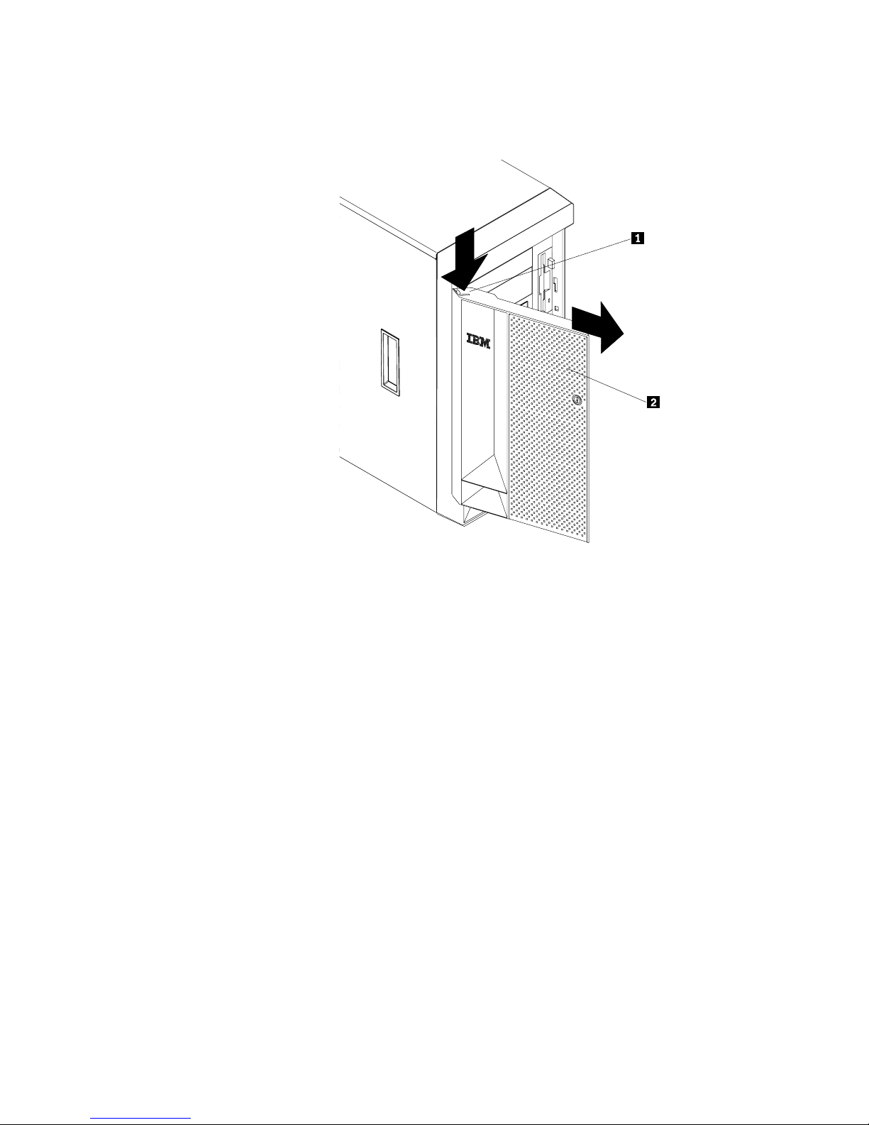
Removing the server door (tower model)
Refer to the following illustration while you perform the steps in this procedure.
C
PU
VR
M
M
EM
OR
P
HD
CI B
Y
D
US
A
B
N
MI
P
OWE
SM
R SUP
I
SERVIC
1
PL
2 3
BUS
Y
E P
R
O
CE
FA
S
N
SO
N
ON RE
R
DU
ND
1
2 3
ANT
TEM
P
ER
A
TUR
E
1
2
1 Flange
2 Server door
To remove the server door:
1. Unlock and open the server door 2.
2. Locate the flange 1 on the top edge of the door.
3. Press down on the flange while pressing out on the door; then lift the server
door up and off the hinge. Set the door aside in a safe place.
50 IBM xSeries User's Reference
Page 61

Removing the trim bezel
Refer to the following illustrations while you perform the steps in this procedure.
Tower model
C
P
U
V
R
M
M
E
M
O
P
H
R
C
D
Y
I
D
B
U
S
A
B
N
M
P
I
O
W
S
M
E
R
I
S
U
S
P
E
1
P
R
L
V
BU
Y
I
C
2
S
E
P
3
R
O
C
E
FA
S
N
S
N
O
O
N
R
R
E
D
U
N
1
D
A
2
N
T
3
T
E
M
P
E
R
A
T
U
R
E
2
3
1 Bezel-release lever
2 Trim bezel
3 Side with bezel tabs and slots
To remove the trim bezel:
1. Move the blue bezel-release lever 1 following the curve of the lever opening.
2. Lift the bezel tabs out of the slots 3 and pull the bezel 2 away from the
server front. Store the bezel in a safe place.
Chapter 4. Installing options 51
Page 62

Rack model
1 Bezel-release lever
2 Trim bezel
3 Side with bezel tabs and slots
To remove the trim bezel:
1. Move the blue bezel-release lever 1 following the curve of the lever opening.
2. Lift the bezel tabs out of the slots 3 and pull the bezel 2 away from the
server front. Store the bezel in a safe place.
52 IBM xSeries User's Reference
Page 63
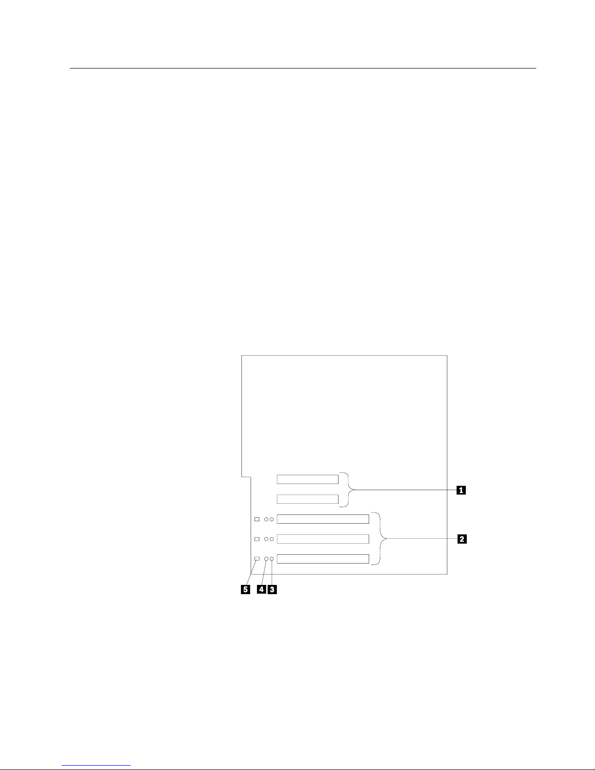
Working with adapters
You can install up to five peripheral component interconnect (PCI) adapters in the
expansion connectors, called slots, on the system board of your server.
In three of the PCI slots, you can install a new PCI adapter or replace an existing
PCI adapter with the same type of adapter without turning off the server power and
restarting the system, if these features are supported by your operating system.
These slots are sometimes called Active PCI, hot-pluggable PCI, or hot-plug PCI
slots. The two remaining PCI slots support standard (non-hot-plug) PCI adapters.
PCI
Your server comes with a video controller. This video controller is an integrated
component on the system board. It is not in an expansion slot. The integrated
video controller has super video graphics array (SVGA) technology.
The integrated video controller is not removable. If you want to disable this
controller and use a video adapter instead, you can install a video adapter in an
expansion slot. When you install a video adapter, the server BIOS automatically
disables the integrated video controller.
The following illustration shows the location of the PCI expansion slots on the
system board.
1 Non-hot-plug 32-bit PCI slots 1 and 2 (on PCI bus A)
2 Hot-plug 64-bit PCI slots 3–5 (on PCI bus B)
3 Power LEDs for hot-swap slots
4 Internal Attention LEDs for hot-swap slots
5 External Attention LEDs for hot-swap slots
Chapter 4. Installing options 53
Page 64

LEDs for hot-plug PCI slots
Each hot-plug PCI slot has three LEDs associated with it — two Attention LEDs
and one Power LED.
Power LED: This LED is on when the hot-plug PCI slot is active and has
power. An adapter must not be added to or removed from the PCI slot when
the Power LED is on. When this LED is off, the PCI slot is inactive and has no
power applied. An adapter can be installed when the Power LED for the PCI
slot is off. Refer to your operating system documentation to determine if it
supports hot-plug PCI adapters, and, if so, how to disable the hot-plug PCI slot.
Attention LEDs: Each hot-plug PCI slot has an Attention LED that is visible
from the rear of the server and one that can be seen from inside the server.
(The LEDs have the same meaning; they are duplicated to be visible from
outside or inside the server.) An Attention LED flashes approximately once per
second when it is on. The meaning of the Attention LEDs is defined by your
operating system. Refer to your operating system documentation to determine
if it supports hot-plug PCI adapters and, if so, what the Attention LEDs indicate.
The following table describes the LEDs:
Power LED Attention LED Description
On Flashing The adapter requires attention. Slot still has
power applied. Do not remove or install an
adapter in the slot. Refer to your operating
system documentation for instructions.
On Off Normal operation; no intervention is required.
Off Flashing The adapter requires intervention. Power is
removed from the slot. An adapter can be
removed or installed in the slot.
Off Off Power is removed from the slot. An adapter
can be removed or installed in the slot.
54 IBM xSeries User's Reference
Page 65

Adapter considerations
Before you continue with the adapter-installation procedure:
Review the documentation that comes with the adapter and follow those
instructions in addition to the instructions provided in this chapter. If you need
to change the switch or jumper settings on your adapter, follow the instructions
that come with the adapter documentation.
You can install full-length adapters in all expansion slots.
You can install hot-plug PCI adapters in PCI slots 3–5, if your operating system
supports this feature. Non-hot-plug PCI adapters can also be installed in these
slots.
Your server supports 5.0V and universal PCI adapters; it does not support
3.3 V adapters.
Note: A universal PCI adapter supports both 3.3V and 5.0V operation.
Your server uses a rotational interrupt technique to configure PCI adapters.
Because of this technique, you can install a variety of PCI adapters that
currently do not support sharing of PCI interrupts.
PCI slots 1 and 2 are on PCI bus A, and PCI slots 3–5 are on PCI bus B. Both
PCI buses are primary buses. The system scans PCI slots 1 through 5 to
assign system resources; then the system starts (boots) the PCI devices in the
following order, if the default boot precedence has not been changed: PCI
slots 1 and 2, system board SCSI devices, and then PCI slots 3 through 5.
See “Start Options” on page 27 for information about changing the boot
precedence.
Note: The performance of the PCI adapters depends on the configuration of
adapters in your system.
Enabling hot-plug PCI support
Your server has hot-plug PCI capability. In order to enable this feature, you must
install the operating system services for hot-plug PCI support code. You can obtain
the operating system hot-plug PCI support code from
http://www.ibm.com/pc/support on the World Wide Web.
IO-compliant statement
I2O is a new standard architecture for intelligent I/O that offloads low-level interrupts
from the server processor to input/output processors (IOPs) designed specifically to
handle I/O. I2O-compliant adapters can improve I/O performance in high-bandwidth
applications, such as client/server processing, video, and groupware.
The xSeries 240 is intended to support I2O-compliant (deep) adapters as listed in
the ServerProven program. A deep adapter is a PCI card that has an embedded
input/output processor (IOP). For the deep adapter to function correctly, the
following items are needed:
An operating system service module (OSM), provided by an operating system
vendor, that supports the class of adapter (such as storage) that is being
installed in the server.
A hardware device module (HDM), provided by a PCI-card vendor.
Chapter 4. Installing options 55
Page 66

Installing a hot-plug PCI adapter
Attention: All hot-plug operations must be done through the operating system
console (or supported user interface). Otherwise, the system might lock up or
serious damage to the adapter or system unit might occur.
This section contains the procedure for installing a hot-plug PCI adapter. If you
want to remove a hot-plug adapter, reverse the steps. If your operating system
supports hot-replace PCI adapters, you can replace a failing hot-plug PCI adapter
with a new adapter of the same type without turning off power to the server. If your
operating system and adapter also support the hot-add feature, you can install a
new adapter without turning off the power to the server.
Note: You do not need to turn off the server to install or remove a hot-plug PCI
adapter.
Before you begin:
Read “Electrical safety” on page 42 and “Handling static-sensitive devices”
on page 44.
Read the documentation that comes with your adapter for any special
requirements or restrictions.
Read the documentation that comes with your operating system.
Attention: Do not remove a hot-plug adapter before performing the
operating-system-defined procedure for disabling the hot-plug PCI slot that contains
the adapter. Failure to do so might cause your system to lock up. Refer to your
operating system documentation.
56 IBM xSeries User's Reference
Page 67

Refer to the following illustrations of the rack model while you perform the steps in
this procedure.
Chapter 4. Installing options 57
Page 68

1 Expansion-slot cover
2 Tab
3 Adapter retention latch
4 Adapter retention flap
5 Plastic divider
6 Power light
7 Attention light
8 Adapter
9 SCSI cable extender
Note: For some server models, the SCSI cable extender differs slightly from what
is shown in the preceding illustration. In these models the retaining bracket
holding the cable connector has been removed.
To install a hot-plug PCI adapter:
1. Remove the cover. See “Removing the left-side cover (tower model)” on
page 48 or “Removing the cover (rack model)” on page 49.
2. Determine which PCI adapter expansion slot you will use for the adapter.
Note: You can use only PCI slots 3–5 hot-plug PCI adapters.
3. Disable the selected PCI slot from your operating system. (Refer to the
documentation that comes with your operating system for information about
disabling a hot-plug PCI slot.) Disabling the PCI slot turns off the Power light
for that PCI slot.
Attention: Make sure the Power light 6 for the hot-plug PCI slot is off before
you continue to the next step.
4. Remove the expansion-slot cover 1:
a. Rotate the adapter retention latch 3 counterclockwise.
58 IBM xSeries User's Reference
Page 69

b. Lift the tab 2 covering the top of the expansion-slot cover 1 and then
remove the expansion-slot cover from the server. Store it in a safe place
for future use.
Attention: Expansion-slot covers must be installed on all vacant slots.
This maintains the electromagnetic emissions characteristics of the system
and ensures proper cooling of system components.
5. Refer to the documentation that comes with your adapter for any cabling
instructions. It might be easier for you to route any cables before you install
the adapter.
6. Press on the touchpoint on the adapter retainer flap 4 at the end of the slot
nearest the front of the server and rotate the adapter retainer flap upward.
7. Remove the adapter from the static-protective package.
Attention: Avoid touching the components and gold-edge connectors on the
adapter.
8. Place the adapter, component-side up, on a flat, static-protective surface.
9. Install the adapter 8:
a. Carefully grasp the adapter 8 by its top edge or upper corners, and align
it with the expansion slot on the system board.
b. Press the adapter firmly into the expansion slot.
Attention: When you install an adapter in the server, be sure that it is
completely and correctly seated in the system-board connector. Incomplete
insertion might cause damage to the system board or the adapter.
c. Lower the tab 2 on the adapter guide over the tab on the top corner of
adapter. Rotate the adapter retention latch 3 clockwise until it snaps into
place.
Attention: Power cannot be restored to the adapter slot if the tab is not
lowered into place.
d. Close the adapter retainer flap 4.
10. Connect any needed cables to the adapter.
Attention: Route cables so that the flow of air from the fans is not blocked.
11. Enable the PCI slot from your operating system. (Refer to the documentation
that comes with your operating system for information about enabling a
hot-plug PCI slot.) Make sure that the Power light 6 for the hot-plug PCI slot
is on.
12. If you have other options to install or remove, do so now; otherwise, go to
“Completing the installation” on page 85.
Chapter 4. Installing options 59
Page 70

Installing a non-hot-plug adapter
This section contains the procedure for installing a non-hot-plug adapter. If you
want to remove a non-hot-plug adapter, reverse the steps.
Before you begin:
Read “Electrical safety” on page 42 and “Handling static-sensitive devices”
on page 44.
Read the documentation that comes with your option.
Refer to the illustrations in “Installing a hot-plug PCI adapter” on page 56 while you
perform the steps in this procedure.
To install a non-hot-plug adapter:
1. Turn off the server and peripheral devices and disconnect all external cables
and power cords (see “Preparing to install options” on page 46); then, remove
the cover. See “Removing the left-side cover (tower model)” on page 48 or
“Removing the cover (rack model)” on page 49.
2. Determine which PCI adapter expansion slot you will use for the adapter.
Note: Check the instructions that come with the adapter for any requirements
or restrictions.
3. Remove the expansion-slot cover 1:
a. Rotate the adapter retention latch 3 counterclockwise.
b. Remove the expansion-slot cover from the server. Store it in a safe place
for future use.
Attention: Expansion-slot covers must be installed on all vacant slots. This
maintains the electromagnetic emissions characteristics of the system and
ensures proper cooling of system components.
4. Refer to the documentation that comes with your adapter for any cabling
instructions. It might be easier for you to route any cables before you install
the adapter.
5. Press on the touchpoint on the adapter retainer flap 4 at the end of the slot
nearest the front of the server and rotate the adapter retainer flap upward.
6. Remove the adapter from the static-protective package.
Attention: Avoid touching the components and gold-edge connectors on the
adapter.
7. Place the adapter, component-side up, on a flat, static-protective surface.
8. Set any jumpers or switches as described by the adapter manufacturer.
9. Install the adapter 8:
a. Carefully grasp the adapter 8 by its top edge or upper corners, and align
it with the expansion slot on the system board.
b. Press the adapter firmly into the expansion slot.
Attention: When you install an adapter in the server, be sure that it is
completely and correctly seated in the system-board connector before you
60 IBM xSeries User's Reference
Page 71

apply power. Incomplete insertion might cause damage to the system
board or the adapter.
c. Lower the tab 2 on the adapter guide over the tab on the top corner of
the adapter. Rotate the adapter retention latch 3 clockwise until it snaps
into place.
d. Close the adapter retainer flap 4.
10. Connect any needed cables to the adapter.
Attention: Route cables so that the flow of air from the fans is not blocked.
11. If you have other options to install or remove, do so now; otherwise, go to
“Completing the installation” on page 85.
Special considerations for installing a RAID adapter
You can install an optional RAID adapter in your server to control the hot-swap
hard disk drives.
To install the RAID adapter:
1. Disconnect the SCSI cable from the SCSI cable extender on the system board.
See the illustration in “Installing a hot-plug PCI adapter” on page 56 for the
location of the SCSI cable extender. (The other end of the SCSI cable is
connected to the SCSI hard disk drive (HDD) backplane.) The Service label on
the inside of the cover of your server shows cable routing for an optional RAID
adapter.
2. Connect the end of the SCSI cable that you disconnected from the SCSI cable
extender to the RAID adapter. The other end of the cable is connected to the
SCSI HDD backplane; the drives in the hot-swap bays are now connected to
the RAID adapter.
3. Connect the 2-drop SCSI cable to the SCSI cable extender on the system
board, and attach the device in the non-hot-swap bay to one of the drops on
the other end of the 2-drop SCSI cable. The device is attached to the
integrated SCSI controller.
Refer to the documentation provided with the RAID adapter for more information
about installing the adapter and configuring a disk array.
Verifying compatibility between network adapters and device drivers
Your server supports several types of network adapters. If you are having trouble
with the installation or operation of a network adapter or network operating system,
ensure that the network-adapter device driver supports up to four processors.
Refer to your network-adapter documentation for additional information about
adapter compatibility requirements.
Chapter 4. Installing options 61
Page 72

Installing a microprocessor kit
Your server comes with one microprocessor installed on the processor board. If
you install an additional microprocessor kit, your server can operate as a symmetric
multiprocessing (SMP) server. With SMP, certain operating systems and
application programs can distribute the processing load between the
microprocessors. This enhances performance for database and point-of-sale
applications, integrated manufacturing solutions, and other applications.
Before you begin:
Read “Electrical safety” on page 42 and “Handling static-sensitive devices”
on page 44.
Thoroughly review the documentation that comes with the microprocessor,
so that you can determine whether you need to update the server basic
input/output system (BIOS). The latest level of BIOS for your server is
available through the World Wide Web. See Chapter 7, “Getting help,
service, and information” on page 161 for the appropriate World Wide Web
addresses.
Obtain an SMP-capable operating system (optional). For a list of supported
operating systems, see http://www.ibm.com/pc/us/compat/ on the World
Wide Web.
Attention: To avoid damage and ensure proper server operation when you install
a new or an additional microprocessor, use microprocessors that have the same
cache size and type, and the same clock speed. Microprocessor internal and
external clock frequencies must be identical.
Notes:
1. The illustrations in this section might differ slightly from your hardware.
2. To order additional microprocessor options, contact your IBM reseller or IBM
marketing representative.
3. The microprocessor that is installed in microprocessor connector U5 is CPU or
processor 1. If a microprocessor is installed in microprocessor connector U6, it
is CPU or processor 2. If the server has only one microprocessor installed, that
microprocessor is installed in microprocessor connector U5 and is the startup
(boot) processor. If more than one microprocessor is installed, the
microprocessor with the lower stepping level is the startup processor, and the
microprocessor with the higher stepping level is the application processor. If
both microprocessors have the same stepping level, the microprocessor
installed in microprocessor connector U6 is the startup processor, and the
microprocessor installed in U5 is the application processor.
Note: You can determine the stepping levels of the installed microprocessors
using the Configuration/Setup. See “System Summary” on page 22.
62 IBM xSeries User's Reference
Page 73

Refer to the following illustrations while you perform the steps in this section.
6
5
4
1 Terminator card
2 Microprocessor connector 2 (U6)
3 Voltage regulator module (VRM) connector for second VRM
4 VRM for first microprocessor (VRM 1)
5 Microprocessor connector 1 (U5)
6 Microprocessor 1
Chapter 4. Installing options 63
Page 74

7 Microprocessor handle
8 Microprocessor 2
9 VRM for second microprocessor (VRM 2)
To install an additional microprocessor kit:
1. Turn off the server and peripheral devices and disconnect all external cables
and power cords (see “Preparing to install options” on page 46); then, remove
the cover (see “Removing the left-side cover (tower model)” on page 48 or
“Removing the cover (rack model)” on page 49.)
2. Remove the terminator card 1 from the microprocessor connector 2. Store
the terminator card in a safe place in the static-protective package that your
new microprocessor is shipped in; you will need to install it again if you ever
remove the microprocessor.
3. Install the microprocessor:
a. Touch the static-protective package containing the new microprocessor to
any unpainted metal surface on the server; then, remove the
microprocessor from the package.
b. Center the microprocessor 8 over the microprocessor connector 2 and
carefully press the microprocessor into the connector.
4. Install the VRM 9 included in the microprocessor kit:
Attention: When installing or replacing a VRM, use only VRMs specified for
use with your server. Use of other VRMs might cause your server to overheat.
a. Center the VRM 9 over the VRM connector 3. Make sure that the
VRM is oriented and aligned correctly.
b. Press the VRM into the connector.
Notes:
1) To remove a microprocessor, pull upward on the microprocessor
handle 7.
2) If you remove the microprocessor later, remember to install the
terminator card in the appropriate microprocessor connector and to
remove the VRM for that microprocessor.
5. If you have other options to install or remove, do so now; otherwise, go to
“Completing the installation” on page 85.
64 IBM xSeries User's Reference
Page 75

Installing memory-module kits
Adding memory to your server is an easy way to make programs run faster. You
can increase the amount of memory in your server by installing options called
memory-module kits. Each kit contains one industry-standard, dual-inline memory
module (DIMM). Your server uses a noninterleaved memory configuration.
Your server comes with a DIMM installed on the processor board in DIMM
connector 4 (J1). You must install the largest DIMM in the memory connector
farthest from the microprocessor (DIMM connector 4). If you install two DIMMs,
you must install the second one in the memory connector closest to the
microprocessor (DIMM connector 1). If you install three DIMMs, you must install
the third one in DIMM connector 2. If you install four DIMMs, you must install the
fourth one in DIMM connector 3.
Note: The size of the DIMMs in the other memory connectors (DIMM connectors
1, 2, and 3) does not matter. Refer to the following table for some typical
memory configurations.
Table 3. Typical memory configurations
DIMM 4 DIMM 3 DIMM 2 DIMM 1
512 MB 128 MB
512 MB 256 MB 128 MB
512 MB 512 MB 256 MB 512 MB
512 MB 512 MB 512 MB 512 MB
Note: Your server supports 128MB, 256MB, 512MB, and 1GB DIMMs. Your
server supports a minimum of 128MB and a maximum of 4GB of system
memory. Only 133MHz, 3.3 V, 168-pin, 8-byte, 72-bit registered,
synchronous-dynamic-random-access memory (SDRAM), error correcting
code (ECC) with x4 configuration DIMM memory complying with PC 133
Registered DIMM Specification, Revision 1.0 or later is supported. When
installed in systems using 100MHz front-side bus processors, the memory
operates at 100MHz.
5
4
3
Chapter 4. Installing options 65
Page 76

1 DIMM
2 Retaining clips
3 DIMM connector 1 (J4)
4 DIMM connector 2 (J3)
5 DIMM connector 3 (J2)
6 DIMM connector 4 (J1)
Before you begin:
Read “Electrical safety” on page 42 and “Handling static-sensitive devices”
on page 44.
Read the documentation that comes with your option.
To install a DIMM:
1. Turn off the server and peripheral devices and disconnect all external cables
and power cords (see “Preparing to install options” on page 46); then remove
the cover. See “Removing the left-side cover (tower model)” on page 48 or
“Removing the cover (rack model)” on page 49.
2. Locate the DIMM connectors on the processor board. Determine the DIMM
connector into which you will install the DIMM. (See the notes at the beginning
of this procedure.)
3. Touch the static-protective package containing the DIMM to any unpainted
metal surface on the server. Then, remove the DIMM from the package.
Note: To avoid breaking the retaining clips or damaging the DIMM connectors,
handle the clips gently.
4. Install the DIMM:
a. Turn the DIMM 1 so that the pins align correctly with the connector 5.
b. Insert the DIMM into the connector by pressing on one edge of the DIMM
and then on the other edge of the DIMM. Be sure to press straight into the
connector. Be sure that the retaining clips 2 snap into the closed
positions.
c. Make sure the retaining clips are in the closed position. If a gap exists
between the DIMM and the retaining clips, the DIMM has not been properly
installed. In this case, open the retaining clips and remove the DIMM; then,
reinsert the DIMM.
d. Repeat these steps for each DIMM that you install.
Attention:
Installing or removing DIMMs changes the configuration information in the
server. When you restart the server, the system displays a message indicating
that the memory configuration has changed.
If you installed additional memory, start the Configuration/Setup Utility
program and select Save Settings.
If you just replaced a failed DIMM, you must start the Configuration/Setup
Utility program, select Advanced Setup, select Memory Settings, highlight
the connector or bank of connectors that you want to enable, then select
Enable.
66 IBM xSeries User's Reference
Page 77

In some memory configurations, the 3-3-3 beep code might sound during
POST followed by a blank display screen. If this occurs and the Boot Fail
Count feature in the Start Options of the Configuration/Setup Utility is set
to Enabled (its default setting), you must restart the server three times to
force the system BIOS to reset the memory connector or bank of
connectors from Disabled to Enabled.
5. If you have other options to install or remove, do so now; otherwise, go to
“Completing the installation” on page 85.
Installing internal drives
Different types of drives allow your system to read multiple types of media and
store more data. Several types of drives are available, such as:
Diskette
Hard disk
CD-ROM
Tape
Internal drive bays
Internal drives are installed in bays. Your server comes with one 3.5-inch, 1.44 MB
diskette drive and one CD-ROM drive.
Tower model
1 Diskette drive bay
2 SCSI ID 0 bay
3 SCSI ID 2 bay
4 SCSI ID 3 bay
5 SCSI ID 4 bay
6 SCSI ID 8 bay
7 SCSI ID 9 bay
8 Hot-swap bays
9 CD-ROM drive bay
1 Non-hot-swap bay B
11 Non-hot-swap bay A
Chapter 4. Installing options 67
Page 78

Rack model
1 Hot-swap bays
2 CD-ROM drive bay
3 Non-hot-swap bay B
4 Non-hot-swap bay A
5 Diskette drive bay B
6 SCSI ID 9 bay
7 SCSI ID 5 bay
8 SCSI ID 4 bay
9 SCSI ID 3 bay
1 SCSI ID 1 bay
11 SCSI ID 0 bay
Your server contains hardware that lets you replace a failed hard disk drive without
turning off the server. Therefore, you have the advantage of continuing to operate
your system while a hard disk drive is removed or installed. These drives are
known as hot-swappable drives. They are also referred to as hot-swap drives.
Each hot-swap drive that you plan to install must have a hot-swap-drive tray
attached. The drive must have a single connector attachment (SCA) connector.
Hot-swap-drive trays come with the hot-swap drives.
Your server comes with a preinstalled 3.5-inch, 1.44 MB diskette drive and a
preinstalled IDE CD-ROM drive.
Bays A and B come without a device installed. These bays are for 5.25-inch,
half-high, removable-media drives, such as tape backup drives. Bays A and B
can be combined into a single full-high bay.
Your server supports only one diskette drive.
Note: The EMI integrity and cooling of the server are both protected by having
bays A and B covered or occupied. When you install a drive, save the
filler panel from the bay, in case you later remove the drive and do not
replace it with another.
If you are installing a device with a 50-pin connector in one of the non-hot-swap
bays (bays A and B), you need a 68-pin to 50-pin converter. To order the
converter, contact your IBM reseller or IBM marketing representative.
Your server supports six slim (1-inch) or three half-high (1.6-inch), 3.5-inch
hot-swap hard disk drives in the hot-swap bays.
The hot-swap bays connect to a SCSI backplane. This backplane is the
printed circuit board behind the bay. The backplane supports up to six hard
disk drives.
The diskette drive uses 1 MB and 2 MB diskettes. For optimum use,
format 1 MB diskettes to 720 KB and format 2 MB diskettes to 1.44 MB.
68 IBM xSeries User's Reference
Page 79

SCSI drives
Some drives have a special design called small computer system interface, or
SCSI. This design allows you to attach multiple drives to a single SCSI channel.
Notes:
1. Any information about SCSI drives also applies to other SCSI devices, such as
tape drives.
2. If you plan to install both internal and external SCSI devices, you must follow
the instructions in “Connecting external options” on page 90, in addition to the
instructions in this section.
A 16-bit (wide) SCSI cable connects the SCSI HDD (hard disk drive) backplane to
an integrated SCSI controller on the system board. An additional 16-bit 2-drop
SCSI cable is shipped, disconnected, inside your server. It is folded and restrained
with a cable clamp to the side of the power supply housing.
If you want to install a device in one of the non-hot-swap bays, you can either:
Install an additional SCSI adapter and use the 2-drop SCSI cable to attach the
device to that adapter.
Install a RAID adapter as follows:
1. Disconnect the SCSI cable from the SCSI cable extender on the system
board. See the illustration in “Installing a hot-plug PCI adapter” on page 56
for the location of the SCSI cable extender. (The other end of the SCSI
cable is connected to the SCSI HDD backplane.)
2. Connect the end of the SCSI cable that you disconnected from the SCSI
cable extender to the RAID adapter. The other end of the cable is
connected to the SCSI HDD backplane; the drives in the hot-swap bays are
now connected to the RAID adapter.
3. Connect the 2-drop SCSI cable to the SCSI cable extender on the system
board, and attach the device in the non-hot-swap bay to one of the drops
on the other end of the 2-drop SCSI cable. The device is attached to the
integrated SCSI controller.
SCSI IDs
Each SCSI device that is connected to an individual channel of a SCSI controller
needs a unique identification (ID) so that the controller can identify the devices and
ensure that different devices do not attempt to transfer data at the same time. If
you need to set IDs for SCSI devices, refer to the instructions that come with those
devices.
Your server automatically sets SCSI IDs for hot-swap hard disk drives. The SCSI
ID assigned to each hot-swap bay is shown on your server beside the bay and in
the illustrations in “Internal drive bays” on page 67. The server uses the hard disk
drive SCSI IDs to send status information to the indicator lights above each
hot-swap bay.
The SCSI backplane in the server supports up to six hot-swap bays.
The processing sequence for SCSI devices proceeds from the lowest SCSI ID to
the highest (0 to 6, then 8 to 15).
Chapter 4. Installing options 69
Page 80

Termination (internal SCSI devices)
SCSI buses must be terminated at each end. The ends of the SCSI buses in your
server are already terminated.
All the hot-swap drives in your server have automatic termination, and the SCSI
controller provides termination at the other end of the SCSI bus.
You must disable termination on any SCSI devices that you install in the
non-hot-swap bays. Refer to the information that come with the SCSI device for
instructions about setting device jumpers or switches that control termination.
Preinstallation steps (all bays)
Before you install drives in your server, verify that you have all the cables and any
other equipment specified in the documentation that comes with the internal drive.
You might also need to perform certain preinstallation activities. Some of the steps
are required only during the initial installation of an option.
Before you begin:
Read “Electrical safety” on page 42 and “Handling static-sensitive devices”
on page 44.
Read the documentation that comes with the internal drive.
1. Choose the bay in which you want to install the drive.
2. Check the instructions that come with the drive to see if you need to set any
switches or jumpers on the drive.
3. To install the drive, go to “Installing a non-hot-swap drive” on page 71 or
“Installing a drive in a hot-swap bay” on page 73.
70 IBM xSeries User's Reference
Page 81

Installing a non-hot-swap drive
Before you begin:
Read “Electrical safety” on page 42 and “Handling static-sensitive devices”
on page 44.
Read the documentation that comes with your drive.
Prepare the drive for installation (see “Preinstallation steps (all bays)” on
page 70).
Note: The EMI integrity and cooling of the server are both protected by having the
non-hot-swap bays covered or occupied. When you install a drive, save the
filler panel from the bay, in case you later remove the drive and do not
replace it with another.
Refer to the following illustration of the tower model while you perform the steps in
this procedure.
1 Digital linear tape (DLT) drive
2 Filler panel
3 Blue slide rails
4 Metal slide rails
Chapter 4. Installing options 71
Page 82

To install a non-hot-swap drive in one of the non-hot-swap bays:
1. Turn off the server and peripheral devices (see “Preparing to install options” on
page 46) and then remove the cover. See “Removing the left-side cover
(tower model)” on page 48 or “Removing the cover (rack model)” on page 49.
2. Remove the trim bezel. (See “Removing the trim bezel” on page 51.)
3. Remove the filler panel 2 from the bay opening by pulling the filler panel
away from the server. You do not need the filler panel when you have a drive
installed in the bay.
4. Touch the static-protective bag containing the drive to any unpainted metal
surface on the server; then, remove the drive from the bag and place it on a
static-protective surface.
5. Set any jumpers or switches on the drive according to the documentation that
comes with the drive.
6. Install rails on the drive.
If you are installing a standard-size drive:
a. Pull the blue slide rails 3 off the back of the filler panel.
b. Clip the rails onto the sides of the drive.
If you are installing a digital linear tape (DLT) backup drive 1, the slide
rails 4 and screws are included in the box with your server
documentation.
7. Place the drive so that the slide rails engage in the bay guide rails. Push the
drive into the bay until it clicks into place.
8. If you have not already done so, install an optional SCSI adapter. (See to
“Working with adapters” on page 53 for information about installing an
adapter.) See “SCSI drives” on page 69 for information about optional SCSI
adapters, installation of drives in the non-hot-swap bays, and the 16-bit 2-drop
SCSI cable that is provided for use with optional SCSI adapters.
9. Connect one of the connectors on the SCSI cable for the non-hot-swap drive
bays to the back of the drive 1.
10. Connect a power cable to the back of the drive. Power cables for
non-hot-swap drives come installed in your server. The connectors are keyed
and can be inserted only one way.
11. If you are installing another non-hot-swap drive, do so at this time. Otherwise,
continue with the next step.
12. If you have other options to install or remove, do so now; otherwise, go to
“Completing the installation” on page 85.
72 IBM xSeries User's Reference
Page 83

Installing a drive in a hot-swap bay
The hot-swap drive bays support hot-swap drives only.
This section contains the procedure for installing a hot-swap hard disk drive. If you
want to remove a drive, reverse the following steps.
Notes:
1. To minimize the possibility of damage to the hard disk drives when you are
installing a hard disk drive in a rack model, install the rack model in the rack
before installing the hard disk drives.
2. You do not have to turn off the server to install hot-swap drives in these bays.
However, you must turn off the server when performing any steps that involve
installing or removing cables.
Before you begin:
Read “Electrical safety” on page 42 and “Handling static-sensitive devices”
on page 44.
Read the documentation that comes with your drive.
If your server has a RAID adapter installed, review the documentation that
comes with your RAID adapter for information about the RAID adapter and
disk-array configuration.
Prepare the drive for installation (see “Preinstallation steps (all bays)” on
page 70).
Refer to the following illustrations of the tower model while you perform the steps in
this procedure.
Chapter 4. Installing options 73
Page 84

1 Filler panel for use with half-high drives
2 Filler panel (slim-high)
HDD
NMI
SMI
SERVICE PROCESSO
BUS
NON REDUNDANT
R
TEMPERATURE
3 Drive
4 Screws
5 Drive tray
6 Drive tray handle (in open position)
74 IBM xSeries User's Reference
Page 85

To install a drive in a hot-swap drive bay:
1. If your server is a tower model, unlock and open the server door.
Attention: To maintain proper system cooling, do not operate the server for
more than two minutes without either a drive or a filler panel installed in each
bay.
2. Remove the filler panel 2 from one of the empty hot-swap bays by inserting
your finger into the depression at the left side of the filler panel and pulling it
away from the server.
Note: If you are installing a half-high hard disk drive, you will need to remove
two adjacent filler panels. The two filler panels should be from either
the top pair of bays, the middle pair of bays, or the bottom pair of bays.
3. If your hard disk drive is not installed on the drive tray 5, place the drive in
the drive tray and, being careful not to over-tighten the screws, attach the drive
to the tray using the four screws provided with the option kit.
4. Install the hard disk drive 3 in the hot-swap bay:
a. Ensure the tray handle 6 is open (that is, perpendicular to the drive).
b. Align the drive/tray assembly so that it engages the guide rails in the bay.
c. Gently push the drive/tray assembly into the bay until the drive connects to
the backplane.
d. Push the tray handle to the right until it locks.
5. If you installed a half-high hard disk drive, install a filler panel 1 in the gap
above the drive:
a. Locate the smaller filler panel 1 that is designed for use with half-high
drives. It is stored on the slim-high filler panel 2 that you removed earlier
in this procedure.
b. Pull the smaller filler panel off the filler panel.
c. Gently push the filler panel 1 into place in the gap above the drive.
6. Check the hard disk drive status indicators to verify that the hard disk drives
are operating properly. See “Identifying problems using status LEDs” on
page 151 for details.
7. If your server is a tower model, close and lock the server door.
Note: If your server has a RAID adapter installed, you must reconfigure your
disk arrays after installing hard disk drives.
Chapter 4. Installing options 75
Page 86

Replacing a drive in a hot-swap bay
You do not have to turn off the server to remove a drive from a hot-swap bay.
Attention:
1. Before you remove a hot-swap hard disk drive that is not defective, back up all
important data.
2. To avoid damage to a hard disk drive, Do not remove the drive from the
hot-swap bay until it has had time to spin down (approximately 30 seconds).
Handle the drive carefully.
3. Before you remove a hot-swap drive, make sure it is defective. If you partially
or completely remove a good drive instead of a defective one your server might
lose valuable data.
This situation is especially relevant if your server has a RAID adapter installed
and you assigned RAID level 1 or 5 to the logical drives in your disk array. The
RAID adapter can rebuild the data that you need, provided that certain
conditions are met. Refer to the information provided with the RAID adapter for
further details.
Before you begin:
Read “Electrical safety” on page 42 and “Handling static-sensitive devices”
on page 44.
Read the documentation that comes with your drive.
If your server has a RAID adapter installed, review the information provided
with the RAID adapter for information about the RAID adapter and
disk-array configuration.
Prepare the drive for installation (see “Preinstallation steps (all bays)” on
page 70).
76 IBM xSeries User's Reference
Page 87

Refer to the following illustration of the tower model while you perform the steps in
this procedure.
H
DD
NM
I
S
M
I
SERVIC
BUS
E PR
OCES
NON
SO
R
RE
DUND
ANT
TEM
PER
A
TU
RE
3 Drive
4 Screws
5 Drive tray
6 Drive tray handle (in open position)
Chapter 4. Installing options 77
Page 88

To replace a drive in a hot-swap bay:
1. If your server is a tower model, unlock and open the server door.
Attention: To maintain proper system cooling, do not operate the server for
more than two minutes without either a drive or a filler panel installed in each
bay.
2. Remove the defective hard disk drive 3 by placing the handle 6 on the
drive to the open position (perpendicular to the drive) and pulling the hot-swap
tray from the bay.
3. Remove the four screws 4 that attach the drive 3 to the hot-swap tray 5,
and remove the drive from the tray.
4. Place the new hard disk drive on the hot-swap tray and, being careful not to
over-tighten the screws, attach the drive to the tray using four screws.
5. Install the hard disk drive in the hot-swap bay:
a. Ensure the tray handle is open (that is, perpendicular to the drive).
b. Align the drive/tray assembly so that it engages the guide rails in the bay.
c. Push the drive assembly into the bay until the drive connects to the
backplane.
d. Push the tray handle to the right until it locks.
6. Check the hard disk drive status indicators to verify that the hard disk drive is
installed properly. See “Identifying problems using status LEDs” on page 151
for details.
7. If your server is a tower model, close and lock the server door.
78 IBM xSeries User's Reference
Page 89

Installing a hot-swap power supply
Your server comes with two power supplies. You can add a third power supply.
After you install a power supply, check the power-supply status indicators to verify
that the power supply is operating properly. See “Power supplies” on page 13 for
details.
8
CAUTION:
Never remove the cover on a power supply or any part that has the
following label attached.
Hazardous voltage, current, and energy levels are present inside any
component that has this label attached. There are no serviceable parts
inside these components. If you suspect a problem with one of these
parts, contact a service technician.
Chapter 4. Installing options 79
Page 90

Refer to the following illustration of the tower model while performing the steps in
this procedure.
Note: You do not need to turn off the power to the server to install hot-swap
power supplies.
1 Power supply
2 Filler panel
3 Cable-restraint bracket
4 Power cord connector
5 Handle on power supply (in open position)
6 AC Power light
7 DC Power light
80 IBM xSeries User's Reference
Page 91

To add a power supply:
1. Remove the filler panel 2 from the empty power supply bay by inserting your
finger into the depression on the filler panel and pulling it away from the server.
Save the filler panel in case you remove the power supply at a later time.
Note: During normal operation, each power-supply bay must have either a
power supply or filler panel installed for proper cooling.
2. Install the power supply 1 in the bay:
a. Place the handle 5 on the power supply in the open position (that is,
perpendicular to the power supply) and slide the power supply into the
chassis.
b. Gently close the handle to seat the power supply in the bay.
3. Plug the power cord for the added power supply into the power cord connector
2.
4. Route the power cord through the cable-restraint bracket 3.
5. Plug the power cord into a properly grounded electrical outlet.
6. Verify that the DC Power light 7 and AC Power light 6 on the power supply
are lit, indicating that the power supply is operating correctly.
7. If you have other options to install or remove, do so now; otherwise, go to
“Completing the installation” on page 85.
Removing a hot-swap power supply
Your server comes with two power supplies. You can add a third power supply.
Each power supply has two status indicators; see “Power supplies” on page 13 for
information about the status indicators.
Attention: If the NON REDUNDANT LED on the diagnostic LED panel is lit, do
not remove a hot-swap power supply without first turning off the server.
Refer to the illustration in “Installing a hot-swap power supply” on page 79 while
you perform the steps in this procedure.
8
CAUTION:
Never remove the cover on a power supply or any part that has the
following label attached.
Hazardous voltage, current, and energy levels are present inside any
component that has this label attached. There are no serviceable parts
inside these components. If you suspect a problem with one of these
parts, contact a service technician.
Chapter 4. Installing options 81
Page 92

To remove a hot-swap power supply:
1. If the NON REDUNDANT LED on the diagnostic LED panel is lit, turn off the
server and peripheral devices (see “Preparing to install options” on page 46);
otherwise, go to the next step.
2. Remove the power supply 1:
a. Unplug the power cord connector from the power supply.
Note: Be careful when you remove the hot-swap power supply; the power
supply might be too hot to handle comfortably.
12
CAUTION:
The following label indicates a hot surface nearby.
b. Remove the defective power supply by placing the handle 5 on the power
supply in the open position (perpendicular to the power supply) and pulling
the power supply from the bay.
3. If you are not replacing the power supply:
a. Install a power-supply filler panel 2.
Note: During normal operation, each power-supply bay must have either a
power supply or filler panel installed for proper cooling.
b. Open the cable-restraint bracket 3 and remove the power cord from the
cable-restraint bracket. Close the cable-restraint bracket.
c. Unplug the power cord from the electrical outlet.
If you are replacing the power supply:
a. Place the handle 5 on the power supply in the open position, and slide
the power supply into the chassis.
b. Gently close the handle on the power supply to seat the power supply in
the bay.
c. Plug the power cord for the power supply into the power cord connector
4.
4. If you have other options to install or remove, do so now; otherwise, go to
“Completing the installation” on page 85.
82 IBM xSeries User's Reference
Page 93

Replacing a hot-swap fan assembly
Your server comes with three hot-swap fan assemblies.
Attention: Replace a fan that has failed within 48 hours to help ensure proper
cooling.
Note: You do not need to turn off the power to the server to replace a hot-swap
fan assembly.
The following illustrations show the replacement of a hot-swap fan assembly. Refer
to these illustrations while performing the steps in this procedure.
C
P
U
H
D
D
V
R
M
M
E
M
O
R
Y
P
C
I
B
U
S
N
M
I
A
B
S
M
I
S
E
R
V
I
C
E
P
R
O
C
BU
E
S
S
S
O
R
P
O
W
E
R
S
U
P
P
L
Y
N
O
N
1
R
E
D
2
U
N
3
D
A
N
T
FA
N
1
T
E
M
2
P
E
3
R
A
T
U
R
E
1 Hot-swap fan assembly 1
2 Fan assembly 1 LED
3 Fan 1 release latch
4 Hot-swap fan assembly 2
5 Fan assembly 2 LED
6 Fan 2 release latch
7 Fan Assembly 3 LED
8 Fan 3 release latch
9 Hot-swap fan assembly 3
Chapter 4. Installing options 83
Page 94

To replace a hot-swap fan assembly:
1. Remove the cover. See “Removing the left-side cover (tower model)” on
page 48 or “Removing the cover (rack model)” on page 49.
Attention: To ensure proper system cooling, do not remove the top cover for
more than 30 minutes during this procedure.
2. Determine which fan assembly (fan 1 1, fan 2 4, or fan 3 9) to replace by
checking the fan LEDs on the diagnostic LED panel (see “Diagnostic LED
panel” on page 153) and the LEDs located on the fan assemblies.
3. Remove the fan assembly from the server by pressing the orange release latch
(3, 6, or 8) for the fan and pulling the fan away from the server.
4. Slide the replacement fan assembly into the server until it clicks into place.
5. Verify that the FAN LED on the diagnostic panel is not lit. If the FAN LED is lit,
reseat the fan.
6. Replace the cover. For a tower model, see “Completing the tower model
installation” on page 85. For a rack model, see “Completing the rack model
installation” on page 88.
84 IBM xSeries User's Reference
Page 95

Completing the installation
To complete your installation, you must reinstall the cover and reconnect all the
cables that you disconnected in “Preparing to install options” on page 46, and, for
certain options, run the Configuration/Setup Utility program. Follow the instructions
in this section.
If you have a tower model, continue with “Completing the tower model
installation.”
If you have a rack model, go to “Completing the rack model installation” on
page 88.
Completing the tower model installation
To complete the installation for the tower model:
1. Install the left-side cover, if it was removed.
C
PU
V
R
M
M
E
M
OR
P
H
CI
Y
D
B
D
U
S
A
B
N
M
I
P
O
W
S
M
E
R
I
S
U
S
PP
ER
1 2
L
V
BUS
Y
IC
E
3
PR
O
C
E
FAN
SS
NO
O
N
R
RE
D
U
N
1 2
D
A
NT
3
T
E
M
P
E
RA
T
U
RE
1 Slots
2 Left-side cover
a. Align the left-side cover 2 with the left side of the server, about 25mm
(1inch) from the front of the server; place the bottom of the left-side cover
on the bottom rail of the left-side side of the chassis.
b. Insert the tabs at the top of the cover into the slots 1 at the top of the
server side.
c. Hold the cover against the server and slide the cover toward the front of
the server until the cover clicks into place.
Chapter 4. Installing options 85
Page 96

2. Install the trim bezel, if it was removed.
C
P
U
V
R
M
M
E
M
O
P
H
R
C
D
Y
I
B
D
U
S
A
B
N
M
P
I
O
W
S
M
E
R
I
S
U
S
P
E
1
P
R
L
V
BU
Y
I
C
2
S
E
P
3
R
O
C
E
FA
S
N
S
N
O
O
N
R
R
E
D
U
N
1
D
A
2
N
T
3
T
E
M
P
E
R
A
T
U
R
E
1 Trim bezel
2 Slots (hidden by bezel)
a. Place the tabs at the bottom edge of the trim bezel 1 in the slots 2 at
the bottom front of the server.
b. Press the top of the bezel toward the server until the bezel clicks into
place.
86 IBM xSeries User's Reference
Page 97

3. Install the server door, if it was removed.
1 Flange
2 Server door
a. Set the door 2 on the bottom hinge.
b. Press the flange 1 downward while pressing the top of the door toward
the server, until the flange connects with the top hinge. Release the flange.
4. Close and lock the server door.
Attention: Be sure to maintain a clearance of at least 127mm (5inches) on
the front and rear of the server to allow for air circulation.
5. If you disconnected any cables from the back of the server, reconnect the
cables; then, plug the power cords into properly grounded electrical outlets.
Note: If necessary, see “Input/output connectors and expansion slots” on
page 11 for connector locations.
6. Restart your server.
7. Update device records and reconfigure your server (see “Updating device
records and reconfiguring the server” on page 90).
Chapter 4. Installing options 87
Page 98
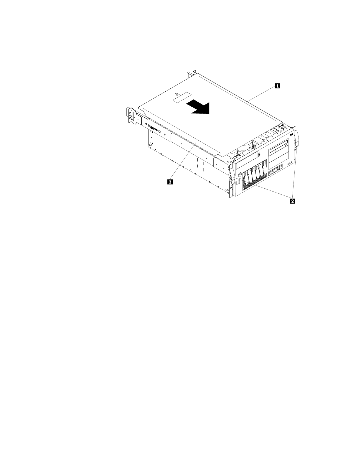
Completing the rack model installation
To complete the installation for the rack model:
1. Install the top cover, if it was removed.
1 Top cover
2 Side latches
3 Flanges
a. Align the top cover 1 with the top of the server, about 25mm (1inch) from
the front of the server; the flanges on the left and right sides of the cover
should be on the outside of the server chassis.
b. Hold the cover against the server and slide the cover toward the front of
the server until the cover clicks into place.
88 IBM xSeries User's Reference
Page 99

2. Install the trim bezel, if it was removed.
1 Bezel-release lever
2 Trim bezel
3 Slots (hidden by bezel)
a. Place the tabs on the left side of the trim bezel in the slots 3 at the left
front of the server.
b. Press the right end of the bezel toward the server until the bezel clicks into
place.
3. If you disconnected any cables from the back of the server, reconnect the
cables; then, plug the power cords into properly grounded electrical outlets.
Note: If necessary, see “Input/output connectors and expansion slots” on
page 11 for connector locations.
4. Slide the server into the rack enclosure until the side latches click into place.
5. Restart your server.
6. Update device records and reconfigure your server (see “Updating device
records and reconfiguring the server” on page 90).
Chapter 4. Installing options 89
Page 100

Updating device records and reconfiguring the server
When you start your server for the first time after you add or remove an internal
option or an external SCSI device, you might see a message telling you that the
configuration has changed.
Some options have device drivers that you need to install. Refer to the
documentation that comes with your option for information about installing any
required device drivers.
If you have more than one microprocessor installed, you might want to upgrade
your operating system. Refer to ServerGuide topic. If you have installed or
removed hard disk drives and your server has a RAID adapter installed, refer to the
documentation provided with your RAID adapter for information about reconfiguring
your disk arrays.
Run the Configuration/Setup Utility program to save the new configuration
information. See Chapter 3, “Configuring your server.”
Connecting external options
Before you begin:
Read “Electrical safety” on page 42 and “Handling static-sensitive devices”
on page 44.
Read the documentation that comes with your options.
Connecting external SCSI devices
You can attach a SCSI storage expansion enclosure to your server.
Cabling requirements
The SCSI controller in your server has one channel that can be used to attach
external devices. This channel is connected to the SCSI connector on the back of
the server and supports 14 unique SCSI IDs. To select and order the correct
cables for use with external devices, contact your IBM reseller or IBM marketing
representative.
For information about the maximum length of SCSI cable between the terminated
ends of the cable, see ANSI SCSI Standards:
X3.131-1986 (SCSI)
X3.131-1994 (SCSI-2)
X3T10/1071D
Adhering to these standards ensures that your server operates properly.
Setting SCSI IDs for external devices
Each SCSI device that is connected to a SCSI controller must have a unique SCSI
ID, so that the SCSI controller can identify the devices and ensure that different
devices do not attempt to transfer data at the same time. SCSI devices that are
connected to different SCSI controllers can have duplicate SCSI IDs. The SCSI
controller uses one of the SCSI IDs; the default SCSI ID for the SCSI controller is
7. See “SCSI IDs” on page 69 and refer to the instructions that come with the
SCSI devices for more information about setting a SCSI ID.
90 IBM xSeries User's Reference
 Loading...