

Page 1
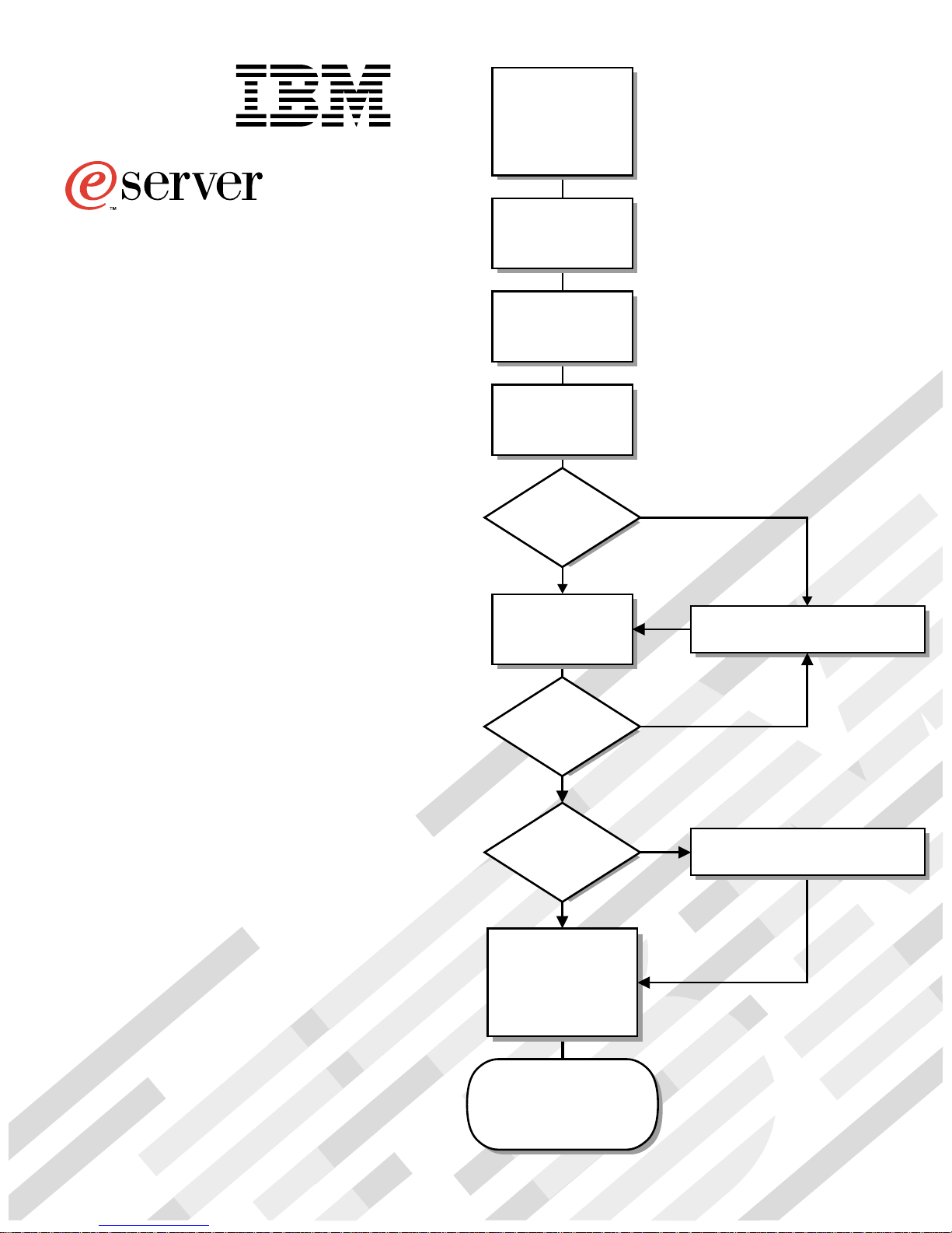
Install options:
• Drives
®
• Microprocessors
• Adapters
• Memory
xSeries 200 (Type 8479)
xSeries 200VL (Type 8481)
Installation Guide
Welcome. . .
Thank you for buying an
IBM xSeries server.
This server
contains information for setting
up and configuring your server.
For detailed information
about your server, view the
User's Reference
Installation Guide
on the
Install the server in
the rack, if required
Cable the server
and options
Start the server
Did the server
start correctly?
Yes
Use ServerGuide™
to set up and
configure hardware
No
Go to the Server Support
flow chart
Documentation CD.
You can also find the most
current information about your
server on the IBM Web site at:
http://www.ibm.com/pc/support
Did configuration
complete?
Yes
Use
ServerGuide to
install operating
system?
Yes
Use ServerGuide to
install applications,
such as IBM systems
management software
and IBM ServeRAID
programs
System is ready to use.
Go to the Server Support
flow chart to register
and profile your server.
No
No
Go to the Web for instructions,
http://www.ibm.com/pc/support
Page 2
-1i.
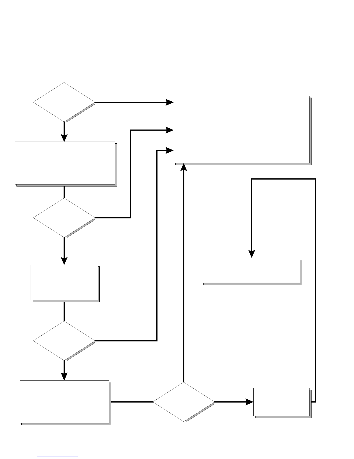
Server Support
Server working
properly?
Yes
No
Check all cables for loose connections
and verify that all optional devices you
installed are on the ServerProven list.
You can view the ServerProven list at:
http://www.ibm.com/pc/compat
Problem
solved?
®
Yes
No
Use the troubleshooting
information provided with
your server to determine
the cause of the problem
and the action to take.
Register and profile your server
After you register and profile, you will be able to:
• Diagnose problems using the IBM Online Assistant
• Participate in the IBM discussion forum
• Receive e-mail notifications of technical updates
related to your profiled products
Register at:
Profile at:
http://www.ibm.com/pc/register
http://www.ibm.com/pc/support
You can view the HelpCenter phone
numbers in the Support Phone List at:
http://www.ibm.com/pc/support
Problem
solved?
Yes
No
Flash the latest levels of BIOS,
diagnostics, and RAID code.
You can download this code at:
http://www.ibm.com/pc/support
Yes
Problem
solved?
No
Phone an
IBM HelpCenter
Page 3

IBM
IBM xSeries 200 and xSeries 200VL
Installation Guide
SC32-P041-70
Page 4

Note:
Before using thi s inf ormation and t he product it supports, be s ure to read th e genera l inf ormation in Append ix A, “W arr anty
information,” on page 39 and Appendix B, “Notices,” on page 49.
Second Edition (September 2001)
© Copyright International Business Machines Corporation 2001. All rights reserved.
US Government Users Restricted Rights – Use, duplication or disclosure restricted by GSA ADP Sc hed ul e C on tr ac t with
IBM Corp.
Page 5

© Copyright IBM Corp. 2001 iii
Contents
Safety. . . . . . . . . . . . . . . . . . . . . . . . . . . . . . . . . . . . . . . . . . . . . . . . . . . . . . . . . . . . . v
Chapter 1.Introduction. . . . . . . . . . . . . . . . . . . . . . . . . . . . . . . . . . . . . . . . . . . . . . . 1
Features and specifications . . . . . . . . . . . . . . . . . . . . . . . . . . . . . . . . . . . . . . . . . . . . 2
Notices and statements used in this book . . . . . . . . . . . . . . . . . . . . . . . . . . . . . . . . . 3
Handling static-sensitive devices . . . . . . . . . . . . . . . . . . . . . . . . . . . . . . . . . . . . . . . . 3
Major components of the xSeries 200 and xSeries 200VL. . . . . . . . . . . . . . . . . . . . . 4
System board internal cable connectors. . . . . . . . . . . . . . . . . . . . . . . . . . . . . . . . . . . 5
Chapter 2.Installing options . . . . . . . . . . . . . . . . . . . . . . . . . . . . . . . . . . . . . . . . . . 7
Moving the stabilizing feet. . . . . . . . . . . . . . . . . . . . . . . . . . . . . . . . . . . . . . . . . . . . . . 7
Removing the side cover . . . . . . . . . . . . . . . . . . . . . . . . . . . . . . . . . . . . . . . . . . . . . . 9
Removing the support-bracket assembly . . . . . . . . . . . . . . . . . . . . . . . . . . . . . . . . . 10
Working with adapters . . . . . . . . . . . . . . . . . . . . . . . . . . . . . . . . . . . . . . . . . . . . . . . 11
Adapter considerations. . . . . . . . . . . . . . . . . . . . . . . . . . . . . . . . . . . . . . . . . . . . . 11
Installing an adapter . . . . . . . . . . . . . . . . . . . . . . . . . . . . . . . . . . . . . . . . . . . . . . . 12
Installing a SCSI or ServeRAID adapter . . . . . . . . . . . . . . . . . . . . . . . . . . . . . . . 14
Installing internal drives . . . . . . . . . . . . . . . . . . . . . . . . . . . . . . . . . . . . . . . . . . . . . . 15
Installing a drive in bay 2 or 4. . . . . . . . . . . . . . . . . . . . . . . . . . . . . . . . . . . . . . . . 16
Installing a hard disk drive in bay 5, 6, or 7 . . . . . . . . . . . . . . . . . . . . . . . . . . . . . 18
Installing memory modules. . . . . . . . . . . . . . . . . . . . . . . . . . . . . . . . . . . . . . . . . . . . 19
Installing a security U-bolt. . . . . . . . . . . . . . . . . . . . . . . . . . . . . . . . . . . . . . . . . . . . . 21
Installing the cover . . . . . . . . . . . . . . . . . . . . . . . . . . . . . . . . . . . . . . . . . . . . . . . . . . 22
Cabling the server. . . . . . . . . . . . . . . . . . . . . . . . . . . . . . . . . . . . . . . . . . . . . . . . . . . 23
Chapter 3.Server power, controls, and indicators. . . . . . . . . . . . . . . . . . . . . . . . 25
Turning on the server . . . . . . . . . . . . . . . . . . . . . . . . . . . . . . . . . . . . . . . . . . . . . . . . 25
Turning off the server . . . . . . . . . . . . . . . . . . . . . . . . . . . . . . . . . . . . . . . . . . . . . . . . 25
Server controls and indicators . . . . . . . . . . . . . . . . . . . . . . . . . . . . . . . . . . . . . . . . . 26
Chapter 4.Configuring your server. . . . . . . . . . . . . . . . . . . . . . . . . . . . . . . . . . . . 27
Starting the utility programs . . . . . . . . . . . . . . . . . . . . . . . . . . . . . . . . . . . . . . . . . . . 28
Using the Configuration/Setup Utility program . . . . . . . . . . . . . . . . . . . . . . . . . . . 28
Using the SCSISelect utility program (some models). . . . . . . . . . . . . . . . . . . . . . 28
Using the PXE boot agent utility program. . . . . . . . . . . . . . . . . . . . . . . . . . . . . . . 29
Using the ServerGuide CDs . . . . . . . . . . . . . . . . . . . . . . . . . . . . . . . . . . . . . . . . . . . 29
Chapter 5.Solving problems . . . . . . . . . . . . . . . . . . . . . . . . . . . . . . . . . . . . . . . . . 31
Diagnostic tools overview . . . . . . . . . . . . . . . . . . . . . . . . . . . . . . . . . . . . . . . . . . . . . 31
POST beep code descriptions . . . . . . . . . . . . . . . . . . . . . . . . . . . . . . . . . . . . . . . . . 31
ServerGuide startup problems . . . . . . . . . . . . . . . . . . . . . . . . . . . . . . . . . . . . . . . . . 32
Troubleshooting chart . . . . . . . . . . . . . . . . . . . . . . . . . . . . . . . . . . . . . . . . . . . . . . . . 33
Chapter 6.Getting information, help, and service . . . . . . . . . . . . . . . . . . . . . . . 35
Getting information . . . . . . . . . . . . . . . . . . . . . . . . . . . . . . . . . . . . . . . . . . . . . . . . . . 35
Using the World Wide Web. . . . . . . . . . . . . . . . . . . . . . . . . . . . . . . . . . . . . . . . . . 35
Getting information by fax. . . . . . . . . . . . . . . . . . . . . . . . . . . . . . . . . . . . . . . . . . . 35
Getting help and service. . . . . . . . . . . . . . . . . . . . . . . . . . . . . . . . . . . . . . . . . . . . . . 35
Using the documentation and diagnostic programs . . . . . . . . . . . . . . . . . . . . . . . 35
Calling for service. . . . . . . . . . . . . . . . . . . . . . . . . . . . . . . . . . . . . . . . . . . . . . . . . 36
Telephone numbers . . . . . . . . . . . . . . . . . . . . . . . . . . . . . . . . . . . . . . . . . . . . . . . 37
Purchasing additional services . . . . . . . . . . . . . . . . . . . . . . . . . . . . . . . . . . . . . . . . . 37
Page 6

iv IBM xSeries 200 and xSeries 200VL: Installation Guide
Appendix A. Warranty information . . . . . . . . . . . . . . . . . . . . . . . . . . . . . . . . . . . . 39
Warranty period . . . . . . . . . . . . . . . . . . . . . . . . . . . . . . . . . . . . . . . . . . . . . . . . . . . . 39
Warranty service and support . . . . . . . . . . . . . . . . . . . . . . . . . . . . . . . . . . . . . . . . . 39
Before you call for service . . . . . . . . . . . . . . . . . . . . . . . . . . . . . . . . . . . . . . . . . . 40
Calling for service. . . . . . . . . . . . . . . . . . . . . . . . . . . . . . . . . . . . . . . . . . . . . . . . . 40
IBM Statement of Limited Warranty Z125-4753-06 8/2000 . . . . . . . . . . . . . . . . . 40
Part 1 - General Terms. . . . . . . . . . . . . . . . . . . . . . . . . . . . . . . . . . . . . . . . . . . . . 40
Part 2 - Country-unique Terms. . . . . . . . . . . . . . . . . . . . . . . . . . . . . . . . . . . . . . . 43
Appendix B. Notices. . . . . . . . . . . . . . . . . . . . . . . . . . . . . . . . . . . . . . . . . . . . . . . . 49
Edition notice . . . . . . . . . . . . . . . . . . . . . . . . . . . . . . . . . . . . . . . . . . . . . . . . . . . . . . 49
Trademarks. . . . . . . . . . . . . . . . . . . . . . . . . . . . . . . . . . . . . . . . . . . . . . . . . . . . . . . . 50
Important notes . . . . . . . . . . . . . . . . . . . . . . . . . . . . . . . . . . . . . . . . . . . . . . . . . . . . 50
Electronic emission notices . . . . . . . . . . . . . . . . . . . . . . . . . . . . . . . . . . . . . . . . . . . 51
Federal Communications Commission (FCC) statement. . . . . . . . . . . . . . . . . . . 51
Industry Canada Class A emission compliance statement . . . . . . . . . . . . . . . . . 51
Australia and New Zealand Class A statement . . . . . . . . . . . . . . . . . . . . . . . . . . 52
United Kingdom telecommunications safety requirement . . . . . . . . . . . . . . . . . . 52
European Union EMC Directive conformance statement. . . . . . . . . . . . . . . . . . . 52
Taiwan electrical emission statement. . . . . . . . . . . . . . . . . . . . . . . . . . . . . . . . . . 52
Japanese Voluntary Control Council for Interference (VCCI) statement . . . . . . . 52
Power cords . . . . . . . . . . . . . . . . . . . . . . . . . . . . . . . . . . . . . . . . . . . . . . . . . . . . . . . 53
Index . . . . . . . . . . . . . . . . . . . . . . . . . . . . . . . . . . . . . . . . . . . . . . . . . . . . . . . . . . . . 55
Page 7
© Copyright IBM Corp. 2001 v
Safety
Before installing this product, read the Safety Information.
Antes de instalar este produto, leia as Informações de Segurança.
Læs sikkerhedsforskrifterne, før du installerer dette produkt.
Lees voordat u dit product installeert eerst de veiligheidsvoorschriften.
Ennen kuin asennat tämän tuotteen, lue turvaohjeet kohdasta Safety Information.
Avant d'installer ce produit, lisez les consignes de sécurité.
Vor der Installation dieses Produkts die Sicherheitshinweise lesen.
Prima di installare questo prodotto, leggere le Informazioni sulla Sicurezza
Les sikkerhetsinformas jo nen (S afety Information) før du installerer dette produktet.
Antes de instalar este produto, leia as Informações sobre Segurança.
Pred instalací tohoto produktu si prectete prírucku bezpecnostních instrukcí.
Page 8

vi IBM xSeries 200 and xSeries 200VL: Installation Guide
Antes de instalar este producto lea la información de seguridad.
Läs säkerhetsinformationen innan du installerar den här produkten.
Page 9
vii
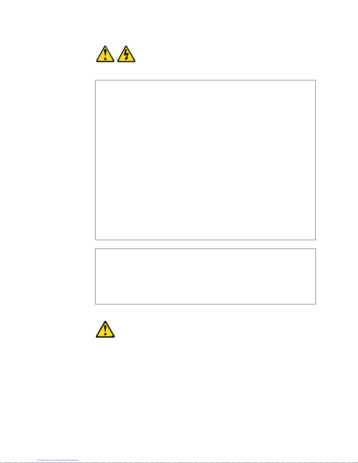
Statement 1
DANGER
Statement 2
CAUTION:
When replacing the lithium battery, use only IBM Part Number 33F8354 or an
equivalent type battery recommended by the manufacturer. If your system has
a module containing a lithium battery , replace it only with the same mod ule type
made by the same manufacturer. The battery contains lithium and can explode
if not properly used, handled, or disposed of.
Do not:
• Throw or immerse into water
• Heat to more than 100
°C (212°F)
• Repair or disassemble
To Connect: To Disconnect:
1. Turn everything OFF.
2. First, attach all cables to devices.
3. Attach signal cables to connectors.
4. Attach power cords to outlet.
5. Turn device ON.
1. Turn everything OFF.
2. First, remove power cords from outlet.
3. Remove signal cables from connectors.
4. Remove all cables from devices.
Electrical current from power, telephone, and communication cables is
hazardous.
To avoid a shock hazard:
• Do not connect or disconnect any cables or perform installation,
maintenance, or reconfiguration of this product during an electrical
storm.
• Connect all power cords to a properly wired and grounded electrical
outlet.
• Connect to properly wired outlets any equipment that will be attached
to this product.
• When possible, use one hand only to connect or disconnect signal
cables.
• Never turn on any equipment when there is evidence of fire, water, or
structural damage.
• Disconnect the attached power cords, telecommunications systems,
networks, and modems before you open the device covers, unless
instructed otherwise in the installation and configuration procedures.
• Connect and disconnect cables as described in the following table
when installing, moving, or opening covers on this product or
attached devices.
Page 10
viii IBM xSeries 200 and xSeries 200VL: Installation Guide
Dispose of the battery as required by local ordinances or regulations.
Statement 3
CAUTION:
When laser products (such as CD-ROMs, DVD drives, fiber optic devices, or
transmitters) are installed, note the following:
• Do not remove the covers. Removing the covers of the laser product could
result in exposure to hazardous laser radiation. There are no serviceable
parts inside the device.
• Use of controls or adjustments or performance of procedures other than
those specified herein might result in hazardous radiation exposure.
DANGER
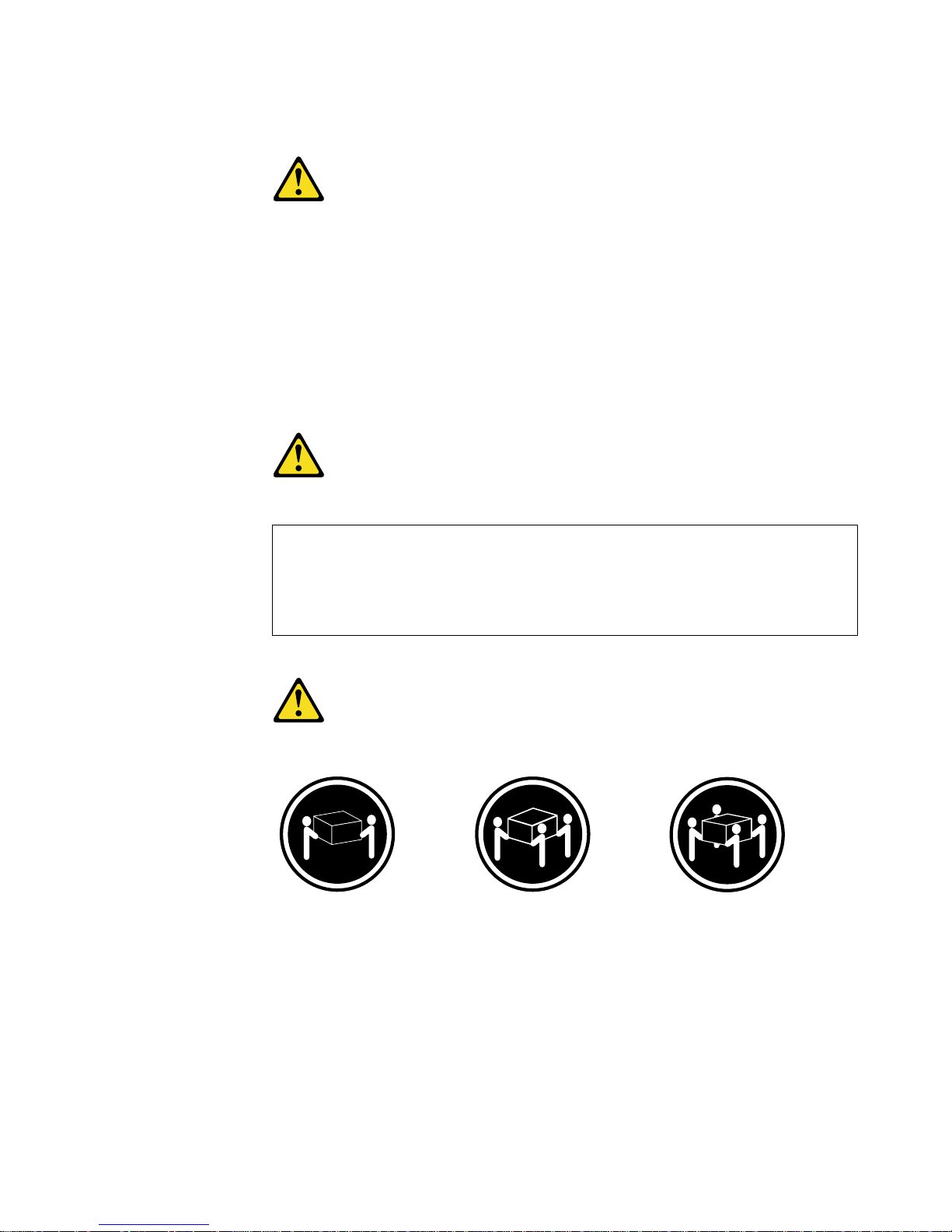
Statement 4
CAUTION:
Use safe practices when lifting.
≥ 18 kg (39.7 lb) ≥ 32 kg (70.5 lb) ≥ 55 kg (121.2 lb)
Some laser products contain an embedded Class 3A or Class 3B laser
diode. Note the following.
Laser radiation when open. Do not stare into the beam, do not view
directly with optical instruments, and avoid direct exposure to the beam.
Page 11
ix
Statement 5
CAUTION:
The power control button on the device and the power switch on the power
supply do not turn off the electrical current supplied to the device. The device
also might have more than one power cord. To remove all electrical current
from the device, ensure that all power cords are disconnected from the power
source.
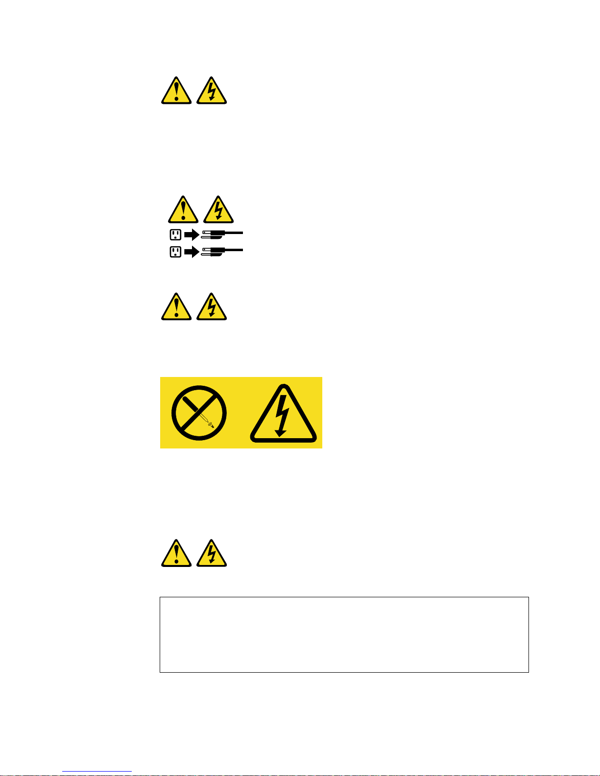
Statement 8
CAUTION:
Never remove the cover on a power supply or any part that has the following
label attached.
Hazardous voltage, current, and energy levels are present inside any
component that has this label attached. There are no serviceable parts inside
these components. If you suspect a problem with one of these parts, contact a
service technician.
Statement 13
DANGER
1
2
Overloading a branch circuit is potentially a fire haz ard and a shock hazard under certain conditions. To avoid these hazards, ensure that your
system electrical requirements do not exceed branch circuit protection
requirements. Refer to the information that is provided with your device
for electrical specifications.
Page 12

x IBM xSeries 200 and xSeries 200VL: Installation Guide
Page 13

© Copyright IBM Corp. 2001 1
Chapter 1. Introduction
Thank you for purchasing an IBM® xSeries 200 or xSeries 200VL server.
This Installation Guide provides the information that is needed to:
• Set up and cable your server
• Start and co nfigur e your server
• Install your network operating system (NOS)
Packaged with the Installation Guide are software CDs that help you to configure
hardware, install device drivers, and install the network operating system.
Also included is an IBM xSeries Documentation CD, which provides detailed
information about your server.
Your server comes with a limited warranty and IBM Server Start Up Support. If you
have access to the World Wide Web, you can obtain up-to-date information about your
server and other IBM server products at the following World Wide Web address:
http://www.ibm.com/eserver/xseries.
The server model and serial numbers are located on labels on the bottom of the
server and on the lower-right side of the bezel.
Note: Your server keys cannot be duplicated by locksmiths. If you lose them, order
replacement keys from the key manufacturer. The key serial number and the
telephone number of the manufacturer are on a tag attached to the keys.
If you plan to install your server in a rack, you need to purchase a Tower-to-Rack Kit
conversion kit. For a list of supported options for your server, see the ServerProven™
list at http://www.ibm.com/pc/compat.
Record your product information in this table.
Product name _____________________________________________
Machine type _____________________________________________
Model number _____________________________________________
Serial number _____________________________________________
Key serial number _____________________________________________
Key manufacturer _____________________________________________
Key phone number _____________________________________________
Page 14

2 IBM xSeries 200 and xSeries 200VL: Installation Guide
Features and specifications
The following table provides a summary of the features and specifications of your
server. Depending on your server model, some features and specifications might not
apply.
Table 1. Features and Specifications.
Microprocessor: Supports one
microprocessor (dependi ng on your
model)
• Intel® Pentium® III with 256 KB o r
512 KB Level-2 cache and
MMX™ (MMX2) technology
or
• Intel
®
Celeron™ with 128 KB
Level-2 cache and MMX (MMX2)
technology
Memory:
• Minimum: 128 MB
• Maximu m: 1.5 GB
• Type: PC133 MHz, ECC SDRAM,
unregistered DIMMs
• Slots: Three dual inline
Drives: (depending on your mod el )
• Diskette: 1.44 MB
• CD-ROM: IDE
• Hard disk drive
Expansion bays: (dep end ing on
your model)
• Two 5.25-in. bays (one CD-ROM
drive installed)
• Two 3.5-in. bays (one diskette
drive installed)
• Three 3.5-in. slim-high bays
available
PCI expansion slots:
• Three 33 MHz/32-bit on the
system board (some models
come with a SCSI adapter
installed)
• Two 33 MHz/32-bit on the PCI
extender board
AGP slot:
Accelerated graphics port (AGP)
(contains the video adapter)
Power supply:
One 330 watt (90-240 V ac)
Video:
• ATI Rage XL video adapter
• Compatible with SVGA and VGA
• 8 MB SDRAM video memory
Size:
• Height: 470 mm (18.5 in.)
• Depth: 508 mm (19.9 in.)
• Width: 165 mm (6.5 in.)
• Weight: approximately 19.5 kg
(43 lb) when fully configured or
15.9 kg (35 lb) minimum
Integrated functions:
• One 10BASE-T/ 100BASE-TX,
Intel Ethernet controller with
Alert on LAN™ and Wake on
LAN® support
• Two serial ports
• Parallel port
• Two USB ports
• Keyboard port
• Mouse port
• MIDI port
• Audio ports
— Line out
— Line in
— Mic
• Dual-channel bus mas tering IDE
controller
Acoustical noise emissions:
• Sound power, idling: 5.1 bel
maximum
• Sound power, operating: 5.3 bel
maximum
Environment:
• Air temperature:
— Server on: 10° to 35° C (50.0°
to 95.0° F). Altitude: 0 to 914
m (2998.7 ft)
— Server on: 10° to 32°C (50.0°
to 89.6° F). Altitude: 914 m
(2998.7 ft) to 2133 m (6998.0
ft)
— Server off: 10° to 43° C (50.0°
to 109.4° F). Maximum
altitude: 2133 m (6998.0 ft)
• Humidity:
— Server on: 8% to 80%
— Server off: 8% to 80%
Heat output:
Approximate heat output in British
thermal units (Btu) per hour
• Minimum configuration: 341 Btu
(100 watts)
• Maximum configuration: 1604 Btu
(470 watts)
Electrical input:
• Sine-wave input (50-60 Hz)
required
• Input voltage low range:
— Minimum: 90 V ac
— Maximum: 137 V ac
• Input voltage high range:
— Minimum: 180 V ac
— Maximum: 265 V ac
• Input kilovolt-amperes (kVA)
approximately:
— Minimum: 0.095 kVA
— Maximum: 0.470 kVA
Page 15

Chapter 1. Introduction 3
Notices and statements used in this book
The caution and danger statements also appear in the multilingual safety book
provided on the IBM xSeries Documentation CD. Each statement is numbered for
easy reference to the corresponding statement in the safety book.
The notice and statement definitions are as follows:
• Notes: These notices provide important tips, guidance, or advice.
• Important: These notices provide information that might help you avoid
inconvenient or problem situations.
• Attention: These notices indicate possible damage to programs, devices, or data.
An attention notice is placed just before the instruction or situation in which
damage could occur.
• Caution: These statements indicate situations that can be potentially hazardous
to you. A caution statement is placed just before the description of a potentially
hazardous procedure step or situation.
• Danger: These statements indicate situations that can be potentially lethal or
extremely hazardous to you. A danger statement is placed just before the
description of a potentially lethal or extremely hazardous procedure step or
situation.
Handling static-sensitive devices
Attention: Static electricity can damage electronic devices and your system. T o av oid
damage, keep static-sensitive devices in their static-protective packages until you are
ready to install them.
To reduce the possibility of electrostatic discharge, observe the following precautions:
• Limit your movement. Movement can cause static electricity to build up around
you.
• Handle the device carefully, holding it by its edges or its frame.
• Do not touch solder joints, pins, or exposed printed circuitry.
• Do not leave the device where others can handle and possibly damage the
device.
• While the device is still in its static-protective package, touch it to an unpainted
metal part of the system unit for at least two seconds. (This drains static electricity
from the package and from your body.)
• Remove the device from its package and install it directly into your system unit
without setting it down. If it is necessary to set the device down, place it in its
static-protective package. Do not place the device on your system unit cover or on
a meta l t a bl e.
• Take additional care when handling devices during cold weather; heating reduces
indoor humidity and increases static electricity.
Page 16
4 IBM xSeries 200 and xSeries 200VL: Installation Guide
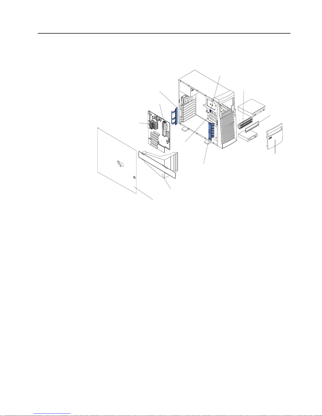
Major components of the xSeries 200 and xSeries 200VL
The following illustration shows the locations of major components in your server.
Note: The illustrations in this document might differ slightly from your hardware.
Adapter retaining
bracket
Adapter support bracket
Drive cage
Microprocessor
Memory modules
Cover
Support bracket assembly
EMC shield
Filler
panel
Intrusion switch
Front door
Page 17
Chapter 1. Introduction 5
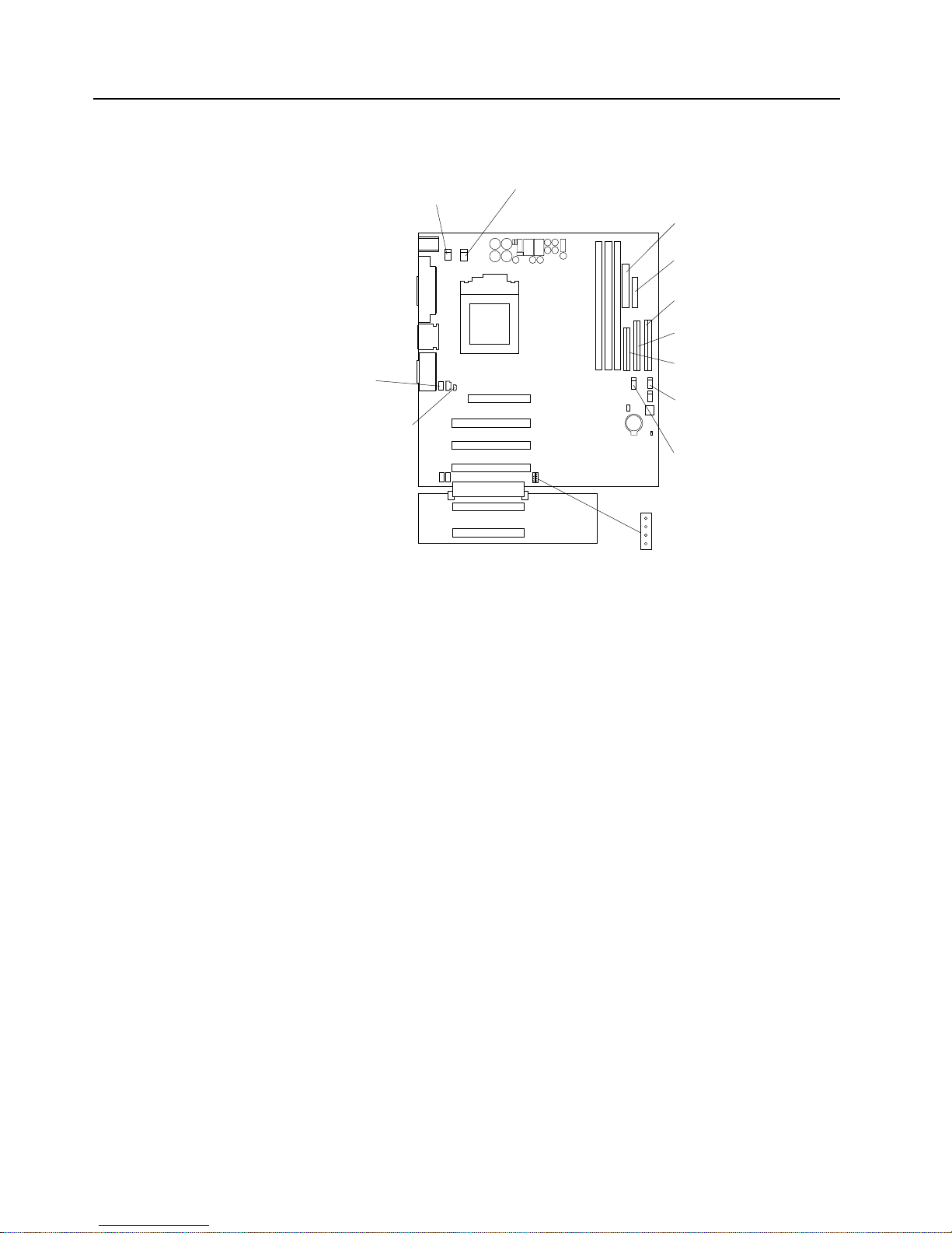
System board internal cable connectors
The following illustration identifies system and extender board connectors for internal
cables.
System fan 2
(SYSFA2)
Support-bracket
assembly fan
(SYSFA3)
Intrusion (J2)
Microprocessor
fan sink
(CPUFA1)
Secondary IDE
(IDE2)
Main power
(JWR1)
Front panel
connector
(J1)
Diskette drive
(FDD1)
Primary IDE
(IDE1)
SCSI LED
(J3)
CD audio
(JCD1)
Internal speaker
(CON2)
Page 18

6 IBM xSeries 200 and xSeries 200VL: Installation Guide
Page 19
© Copyright IBM Corp. 2001 7
Chapter 2. Installing options
This chapter provides instructions to help you install hardware options in your server.
This section is for all users, but is written with the experienced user in mind. If you
need more detailed installation information for options, refer to the User’s Reference
on the IBM xSeries Documentation CD.
Moving the stabilizing feet
The four feet on the bottom of the server provide additional stability when the feet are
placed in the stabilizing pos ition.
If the feet on your system are similar to the feet in the first illustration below, rotate
them a quarter-turn inward to move them out of the way, or a quarter-turn outwards to
provide stability.
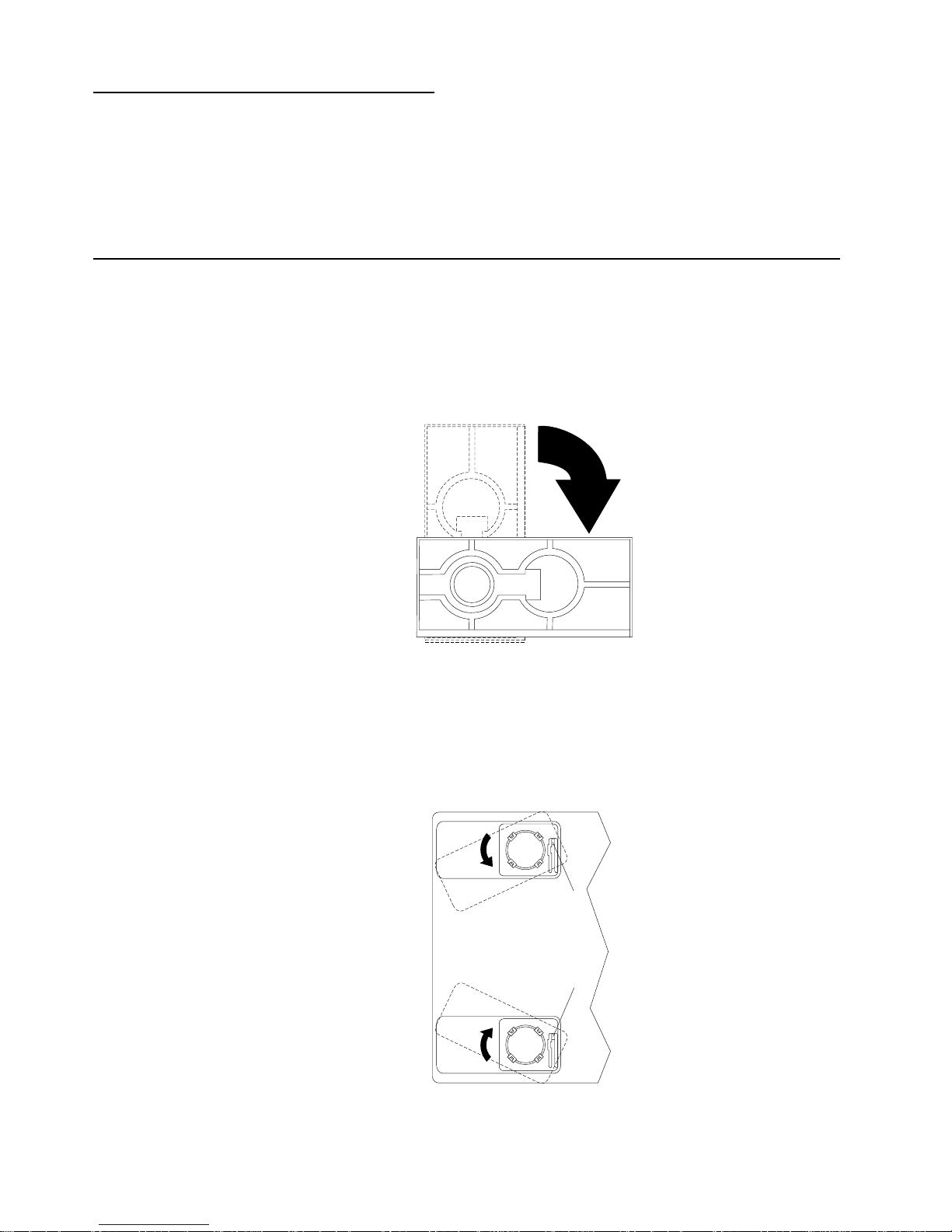
If the feet on your system are similar to the feet in the following illustration, complete
the following steps to place the feet in the stabilizing position.
1. Place the server on its side.
2. Locate the release tab inside the foot; then, lift up on the tab.
Note: The following illustration shows the rear feet located on the bottom rear of
the server.
Release tab
Release tab
Feet (unlocked position)
Page 20
8 IBM xSeries 200 and xSeries 200VL: Installation Guide
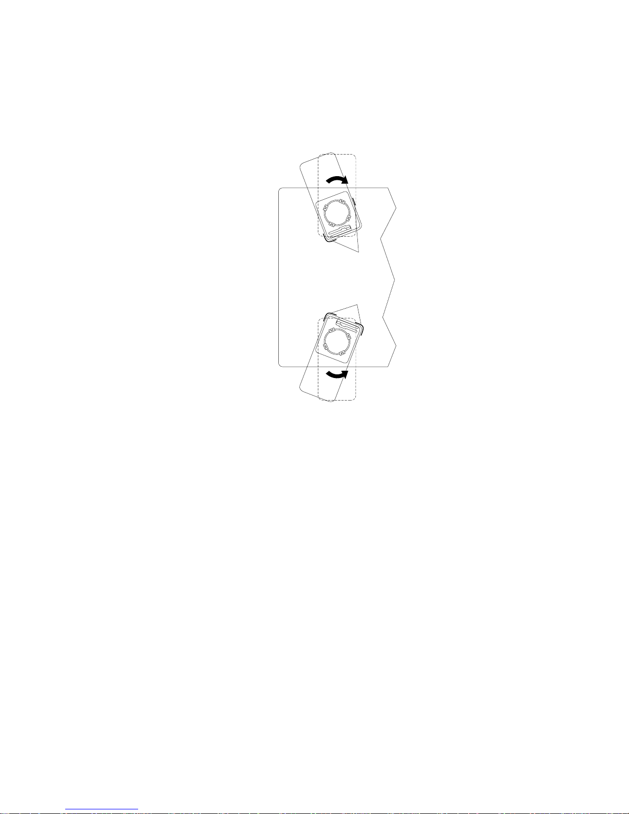
3. Rotate the foot inward to the unlocked position; then, remove the foot from the
server.
4. Align the post in the center of the foot with the hole on the bottom of the server
and place the foot between the guides as indicated.
Note: The following illustration shows the rear feet located on the bottom rear of
the server.
5. Rotate the foot outward until the foot locks into place.
6. Complete steps 2 through 5 for each foot.
Note: When you need to access the inside of the server to install options, you
might find it easier to lay the server on its side. If you do so, mak e sure the
feet are in the horizontal position (see the previous steps). Otherwise, the
feet might break off the server because of the weight of the server.
Feet (locked position)
Guides
Guides
Page 21
Chapter 2. Installing options 9
Removing the side cover
The following information describes how to remove the side cover.
Note: The illustrations in this document might differ slightly from your hardware.
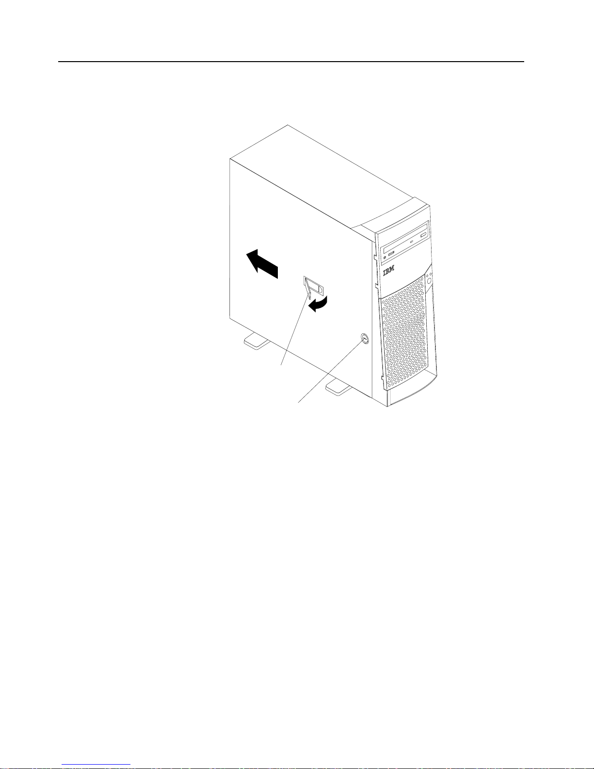
Complete the following steps to remove the side cover of the server.
1. Review the safety precautions listed in “Safety” on page v.
2. Turn off the server and peripheral devices and disconnect all external cables and
power cords.
3. If necessary, unlock the server cover.
4. Pull out on the cover-release latch, which will slide the cover toward the rear of the
server about 12.7 mm (0.5 in.). Then, remove the cover from the server and set it
aside.
To replace the side cover, see “Installing the cover” on page 22.
Attention: For proper cooling and airflow, replace the cover before turning on the
server. Operating the server with the cover removed might damage server
components.
Key lock
Cover-release
latch
Page 22

10 IBM xSeries 200 and xSeries 200VL: Installation Guide
Removing the support-bracket assembly
When working with some options such as hard disk drives, microprocessors, and
memory modules, you must first remove the support-bracket assembly to access the
location of the option.
Complete the following steps to remove the support-bracket assembly.
1. Review the safety precautions listed in “Safety” on page v.
2. Turn off the server and peripheral devices and disconnect all external cables and
power cords; then, remove the side cover. See “Removing the side cover” on
page 9 for details.
3. Disconnect the support-bracket assembly fan cable from the connector (SYSFA3)
on the system board. For the location of the fan cable connector, see “System
board internal cable connectors” on page 5.
4. Locate the end of the support-bracket assembly near the rear of the server. Pull it
out approximately 152.4 mm (6 in.).
5. Pull the front end of the support-bracket assembly away from the server and place
the assembly aside.
To reinstall the support-bracket assembly, reverse these steps.
Page 23

Chapter 2. Installing options 11
Working with adapters
Your server comes with adapter connectors, called slots. The AGP video adapter is
installed in the AGP slot and some server models come with a SCSI adapter installed
in PCI expansion slot 2. You can install up to five PCI adapters in PCI expansion slots
1 through 5. All PCI expansion slots are 32-bit, 33 MHz slots.
Note: The illustrations in this document might differ slightly from your hardware.
The following illustration shows the location of the PCI expansion slots on the system
and PCI extender boards.
Adapter considerations
Before you install an adapter, review the following:
• Locate the documentation that comes with the adapter and follow those
instructions in addition to the instructions given in this chapter. If you need to
change switch or jumper settings on your adapter, follow the instructions that
come with the adapter.
• You can install full-length adapters in all five PCI expansion slots.
• Your server supports 5.0V and universal PCI adapters; it does not support 3.3V
adapters.
• Your server uses a rotational interrupt technique to configure PCI adapters.
Because of this technique, you can install a variety of PCI adapters that currently
do not support sharing of PCI interrupts.
• If you are installing or replacing an adapter that will control your startup (boot)
drive, install the adapter in PCI expansion slot 2.
• PCI expansion slots 1 through 5 are on PCI bus 0.
The system scans the AGP slot and PCI expansion slots 1 through 5 to assign
system resources; then, the system starts (boots) the PCI devices in the following
order, if you have not changed the default boot sequence: PCI expansion slots 1
through 5; then, the system board integrated drive electronics (IDE) or SCSI
devices.
Note: To change the startup sequence for PCI devices, start the
Configuration/Setup Utility program, select Start Options from the main
menu, select Startup Sequence; then, select Second devi c e (SCSI) to
designate the adapter boot sequence. See Chapter 4, “Configuring your
AGP slot
PCI slot 1
PCI slot 2
PCI slot 3
PCI slot 4
PCI slot 5
Page 24

12 IBM xSeries 200 and xSeries 200VL: Installation Guide
server,” on page 27 for details on using the Configuration/Setup Utility
program.
• For a list of supported options for your server, refer to
http://www.ibm.com/pc/compat on the World Wide Web.
Installing an adapter
Refer to the following illustration to install an adapter.
Note: The illustrations in this document might differ slightly from your hardware.
Complete the following steps to install an adapter.
Attention: When you handle static-sensitive devices, take precautions to avoid
damage from static electricity. For details on handling these devices, see “Handling
static-sensitive devices” on page 3.
1. Review the safety precautions listed in “Safety” on page v.
2. Turn off the server and peripheral devices and disconnect all external cables and
power cords; then, remove the side cover. For more information about removing
the side cover, see “Removing the side cover” on page 9.
3. Determine which PCI expansion slot you will use for the adapter.
Note: If you are installing or replacing an adapter that will control your startup
(boot) drive, install the adapter in PCI expansion slot 2.
4. If you are installing a full-length adapter, rotate the front adapter support bracket
to the open (unlocked) position.
5. Rotate the rear adapter retaining bracket to the open (unlocked) position, and
then remove it from the server.
Adapter
retaining
bracket
Expansion
slot cover
Adapter
support
bracket
Adapter
Page 25

Chapter 2. Installing options 13
6. Remove the PCI expansion-slot cover. F r om the rear of the server, press in on the
slot cover. Grasp it a nd p ul l it out of th e s lo t . St or e i t in a s afe plac e for fut ure use.
Attention: PCI expansion-slot covers must be installed on all vacant slots. This
maintains the electronic emissions characteristics of the server and ensures
proper cooling of server components.
7. T ouch the static-protective package containing the adapter to any unpainted metal
surface on the server. Then, remove the adapter from the static-protective
package. Avoid touching the components and gold-edge connectors on the
adapter.
8. Place the adapter, component-side up, on a flat, static-protective surface.
9. Set any jumpers or switches as described by the adapter manufacturer.
10. T o install the adapter, carefully grasp the adapter by its top edge or upper corners,
and align it with the expansion slot guides; then, press the adapter firmly into the
PCI expansion slot.
Attention: When you install an adapter in the server, be sure that it is completely
and correctly seated in the PCI expansion slot before you turn on the server.
Incomplete insertion might cause damage to the system board or the adapter.
11. Connect required cables to the adapter.
Attention: Route cables so that they do not block the flow of air from the fans.
12. If you have another adapter to install, do so now.
13. If you have installed a full-length adapter, rotate the front adapter support bracket
to the closed (locked) position.
14. Reinstall the rear adapter retaining bracket; then, rotate the bracket to the closed
(locked) position.
15. If you have other options to install, do so now.
16. Reinstall the si de cover (see “Installing the cover” on page 22 for details).
17. Reconnect the external cables and power cords; then, turn on the peripheral
devices and the server.
Page 26

14 IBM xSeries 200 and xSeries 200VL: Installation Guide
Installing a SCSI or ServeRAID adapter
Complete the following steps to install a SCSI or ServeRAID™ adapter.
1. If you have not already installed the SCSI adapter, complete steps 1 through 10 of
“Installing an adapter” on page 12. Then, return here to complete the installation.
2. Connect one end of the SCSI signal cable (purchased separately) to the adapter;
then, connect one or more of the signal cable connectors to the rear of the SCSI
devices.
3. Connect the SCSI activity indicator cable (purchased separately) to the adapter
and to the SCSI LED connector (J3) on the system board. See “System board
internal cable connectors” on page 5.
Note: If you are installing or replacing an adapter that will control your startup
(boot) drive, install the adapter in PCI expansion slot 2.
4. If you have another adapter to install or remove, do so now.
5. If you have installed a full-length adapter, rotate the front adapter support bracket
to the closed (locked) position.
6. Reinstall the rear adapter retaining bracket; then, rotate the bracket to the closed
(locked) position.
7. If you have other options to install, do so now.
8. Reinstall the side cover. See “Installing the cover” on page 22 for details.
9. Reconnect the external cables and power cords; then, turn on the peripheral
devices and the server.
Adapter
retaining
bracket
Adapter
support
bracket
SCSI
Adapter
SCSI
activity
indicator
cable
SCSI
LED
(J3)
SCSI signal
cable connector
SCSI activity
indicator cable
connector
SCSI
signal
cable
Page 27

Chapter 2. Installing options 15
Installing internal drives
Your server comes with an IDE CD-ROM drive installed in bay 1, and a 3.5-in., 1.44
MB diskette drive in bay 3. Some sever models have a hard disk drive installed in bay
5.
Drive considerations:
• Diskette drives, tape drives, and CD-ROM drives are removable-media drives.
You can install removable-media drives in bays 1, 2, 3, and 4.
• You can install a 3.5-in., slim-high or a 5.25-in., half-high, removable-media drive,
such as a tape backup drive, in bay 2.
• You can install only a 3.5-in., slim-high, removable-media drive in bay 4.
• The server supports only one diskette drive, which uses 1 MB and 2 MB diskettes.
• Before you install a 3.5-in. drive in a 5.25-in. bay, you must attach the 5.25 in.
conversion kit, supplied with your option, to the 3.5-in. drive. Refer to the
documentation that comes with the option for the conversion kit installation
instructions.
Note: Only 3.5-in. options that ship with proper mounting hardware can be
supported in the 5.25-in. bays.
• If you have a tape backup drive in your server, use a dry process cleaning
cartridge to clean the tape head two hours after you first use a new data cartridge.
Then, clean the tape head once a month, or after each eight hours of continuous
read/write operations, whichever occurs first. For complete details about the tape
backup drive, refer to the documentation that comes with your server or your
backup option.
• The electromagnetic interference (EMI) integrity and cooling of the server are
both protected by having bays 1 through 4 covered or occupied. When you install
Bay 1
Bay 2
Bay 3
Bay 4
Bay 5
Bay 6
Bay 7
Page 28

16 IBM xSeries 200 and xSeries 200VL: Installation Guide
a drive, save the EMC shield and filler panel from the bay, in case you later
remove the drive and do not replace it with another.
• For a list of supported options for your server, refer to
http://www.ibm.com/pc/compat on the World Wide Web.
Installing a drive in bay 2 or 4
Complete the following steps to install a drive in bay 2 or 4.
Attention: When you handle static-sensitive devices, take precautions to avoid
damage from static electricity. For details on handling these devices, see “Handling
static-sensitive devices” on page 3.
1. Review the safety precautions listed in “Safety” on page v.
2. Turn off the server and peripheral devices and disconnect the external cables and
power cords; then, remove the side cover (see “Removing t he sid e co ver ” on page
9 for details).
3. Remove the support-bracket assembly and disconnect the fan cable from the
connector (SYSFA3) on the system board. See “Removing the support-bracket
assembly” on page 10 for details. See “System board internal cable connectors”
on page 5 for the location of the fan cable connector.
4. Use a screwdriver to gently pry the filler panel and EMC shield away from the
server.
Note: If you are installing a drive that is a laser product, observe the following
safety precaution.
EMC shield
Filler panel
Page 29

Chapter 2. Installing options 17
5. Touch the static-protective package containing the drive to any unpainted metal
surface on the server; then, remove the drive from the package and place it on a
static-protective surface.
6. Set any jumpers or switches on the drive according to the documentation that
comes with the drive.
7. Install the drive:
• If you are installing a 5.25-in. drive in bay 2, push the drive into the bay. Then,
use the two screws that come with your option to attach the drive to the drive
cage.
• If you are installing a 3.5-in. drive in bay 2, you must attach the 5.25-in.
conversion kit, supplied with your option, to the 3.5-in. drive.
Note: You can only install a 3.5-in. device in bay 4.
8. Cable the drive:
• If the drive is an IDE device, plug one connector of the IDE signal cable into
the back of the drive and the other end of the cable into the IDE connector
(IDE1) on the system board. For the location of the IDE connectors, see
“System board internal cable connectors” on page 5.
• If the drive is a SCSI device, your server must have a SCSI adapter installed.
Plug one connector of the SCSI signal cable into the back of the drive and the
other end of the cable into the connector on the SCSI adapter. See “Installing
an adapter” on page 12.
Note: Make sure to route the signal cable so that it does not block the air
flow to the rear of the drives or over the microprocessor.
9. If you have another drive to install or remove, do so now.
10. Plug one of the power cables from the power supply into the back of the drive. The
connectors are keyed and can be inserted only one way.
Statement 3
CAUTION:
When laser products (such as CD-ROMs, DVD drives, fiber optic devices, or
transmitters) are installed, note the following:
• Do not remove the cover s. Removi ng the cov ers of the las er product c ould
result in exposure to hazardous laser radiation. There are no serviceable
parts inside the device.
• Use of controls or adjustments or performance of procedures other than
those specified herein might result in hazardous radiation exposure.
Danger
Some laser products contain an embedded Class 3A or Class 3B laser diode. Note
the following. Laser radiation when open. Do not stare into the beam, do not view
directly with optical instruments, and avoid direct exposure to the beam.
Page 30

18 IBM xSeries 200 and xSeries 200VL: Installation Guide
11. Replace the support-bracket assembly and reconnect the fan cable to the
connector (SYSFA3) on the system board. See “System board internal cable
connectors” on page 5 for the location of the fan cable connector.
12. If you have other options to install, do so now.
13. Reinstall the si de cover. See “Installing the cover” on page 22 for details.
14. Reconnect the external cables and power cords; then, turn on the peripheral
devices and the server.
Installing a hard disk drive in bay 5, 6, or 7
Complete the following steps to install a hard disk drive in bay 5, 6, or 7.
Attention: When you handle static-sensitive devices, take precautions to avoid
damage from static electricity. For details on handling these devices, see “Handling
static-sensitive devices” on page 3.
1. Review the safety precautions listed in “Safety” on page v.
2. Turn off the server and peripheral devices and disconnect all external cables and
power cords; then, remove the cover (see “Removing the side cover” on page 9
for details).
3. Remove the support-bracket assembly and disconnect the fan cable from the
connector (SYSFA3) on the system board. See “Removing the support-bracket
assembly” on page 10 for details. See “System board internal cable connectors”
on page 5 for the location of the fan cable connector.
4. Access the drive cage.
a. If your server has hard disk drives installed in the drive cage, disconnect the
power and signal cables from the rear of the drives.
b. Rotate the drive cage out of the server until it locks into place over the drive
cage retention tab.
Drive cage release tab
Drive cage retention tab
Page 31

Chapter 2. Installing options 19
Note: Before you install a hard disk drive, ensure that the drive cage locks
into place over the drive cage retention tab by pressing on the side of
the drive cage.
5. Touch the static-protective package containing the drive to any unpainted metal
surface on the server; then, remove the drive from the package and place it on a
static-protective surface.
6. Set any jumpers or switches on the drive according to the documentation that
comes with the drive.
7. Attach the blue plastic guide rails to the sides of the drive using the screws and
guide rails provided in the drive cage.
8. Slide the drive into the drive cage until the plastic tabs on the guide rails lock into
place in the drive cage.
9. Lift the drive cage up and press in on the drive cage release tab; then, rotate the
drive cage back into the server.
Note: Clear any cables that might impede the replacement of the drive cage.
10. Connect the power and signal cables to the rear of each drive.
Note: Make sure to route the signal cable so that it does not block the air flow to
the rear of the drives or over the microprocessor.
11. If you have other options to install or remove, do so now.
12. Replace the support-bracket assembly and reconnect the fan cable to the
connector (SYSFA3) on the system board. See “Removing the support-bracket
assembly” on page 10 for details. See “System board internal cable connectors”
on page 5 for the location of the fan cable connector.
13. Reinstall the si de cover. See “Installing the cover” on page 22 for details.
14. Reconnect the external cables and power cords; then, turn on the peripheral
devices and the server.
Installing memory modules
Your server comes with a dual in-line memory module (DIMM) installed on the system
board in DIMM connector 1.
Memory considerations:
• When installing additional memory modules, install the second memory module in
DIMM connector 2, and the third in DIMM connector 3. (See the illustration in this
section for memory connector locations.)
• You r se rver supports 128 M B, 256 MB, and 512 MB DIMM s. Your server
supports a minimum of 128 MB and a maximum of 1.5 GB of system memory.
See the ServerProven list at http://www.ibm.com/pc/compat for a list of memory
modules for use with your server.
• Installing or removing DIMMs changes the configuration information in the server.
Therefore, after installing or removing a DIMM, you must change and save the
new configuration information by using the Configuration/Setup Utility program.
When you restart the server, the system displays a message indicating that the
memory configuration has changed. Start the Configuration/Setup Utility program
and select Save Settings. See “Configuring your ser ver” on page 27 for more
information
• The illustrations in this document might differ slightly from your hardware.
Page 32

20 IBM xSeries 200 and xSeries 200VL: Installation Guide
Complete the following steps to install a DIMM.
Attention: When you handle static-sensitive devices, take precautions to avoid
damage from static electricity. For details on handling these devices, see “Handling
static-sensitive devices” on page 3.
1. Review the safety precautions listed in “Safety” on page v.
2. Turn off the server and peripheral devices and disconnect all external cables and
power cords; then, remove the cover (see “Removing the side cover” on page 9
for details).
3. Remove the support-bracket assembly and disconnect the fan cable from the
connector (SYSFA3) on the system board. See “Removing the support-bracket
assembly” on page 10 for details. See “System board internal cable connectors”
on page 5 for the location of the fan cable connector.
4. Install the DIMM:
a. If you are installing a DIMM in connector 1, remove the AGP video adapter.
Remove the AGP video adapter only if you are replacing the DIMM in
connector 1. See “Working with adapters” on page 11 for the location of the
AGP slot.
b. Open the retaining clip on each end of the DIMM connector.
Attention: To avoid breaking the retaining clips or damaging the DIMM
connectors, open and close the clips gently.
c. Touch the static-protective package containing the DIMM to any unpainted
metal surface on the server. Then, remove the DIMM from the package.
d. Turn the DIMM so that the pins align correctly with the connector.
e. Insert the DIMM into the connector by aligning the DIMM edges with the slots
at each end of the DIMM connector. Firmly press the DIMM straight down into
the connector by applying pressure on both ends of the DIMM simultaneously.
DIMM connector 1
DIMM connector 2
DIMM connector 3
Retaining clip
Page 33

Chapter 2. Installing options 21
Be sure that the retaining clips snap into the locked position when the DIMM
is firmly seated in the connector.
f. If a gap exists between the DIMM and the retaining clips, the DIMM has not
been properly installed. In this case, open the retaining clips and remove the
DIMM; then, reinsert the DIMM.
g. If you removed the AGP video adapter, reinstall it now. See “Installing an
adapter” on page 12.
5. If you have other options to install or remove, do so now.
6. Replace the support-bracket assembly and reconnect the fan cable to the
connector (SYSFA3) on the system board. See “Removing the support-bracket
assembly” on page 10 and “System board internal cable connectors” on page 5
for the location of the fan cable connector.
7. Replace the side cover. See “Installing the cover” on page 22.
8. Reconnect the external cables and power cords; then, turn on the peripheral
devices and the server.
If you want to remove a DIMM, reverse these steps.
Installing a security U-bolt
To help prev ent hardware theft, you can add a security U-bolt and cable to your server.
After you add the security cable, make sure that it does not interfere with other cables
that are connected to the server.
Before you begin:
• Obtain the following items:
— A flat-blade screwdriver
— An adjustable wrench
— A 19 mm (0.75 in.) U-bolt or wire rope (similar to National Manufacturing No.
3230, Stock No. 176-735)
— Threa ded nuts that fit the U-bolt
— A security cable
Page 34

22 IBM xSeries 200 and xSeries 200VL: Installation Guide
— A lock, such as a combination lock or padlock
• Read “Safety” on page v and “Handling static-sensitive devices” on page 3.
Complete the following steps to install a U-bolt.
1. Turn off the server and peripheral devices and disconnect all external cables and
power cords; then, remove the cover (see “Removing the side cover” on page 9
for details).
2. Use a screwdriver to remove the two metal knockouts.
3. Insert the U-bolt through the rear panel; then, attach and tighten the nuts.
4. If you have other options to install or remove, do so now.
5. Reinstall the side cover. See “Installing the cover” for details.
6. Thread the cable through the U-bolt and around an object that is a part of or
permanently secured to the building structure or foundation, and from which it
cannot be removed; then, fasten the cable ends together with a lock.
7. Reconnect the external cables and power cords; then, turn on the peripheral
devices and the server.
Installing the cover
The following information describes the cover installation procedure.
Notes:
1. The illustrations in this document might differ slightly from your hardware.
2. If you removed the support-bracket assembly after you removed the cover,
reinstall it before you install the cover. See “Removing the support-bracket
assembly” on page 10 for details.
Page 35

Chapter 2. Installing options 23
Complete the following steps to install the server cover.
1. Clear any cables that might impede the reinstallation of the cover.
2. Install the side cover:
Note: The cover-release latch must be in the unlocked (opened) position before
reinstalling the cover on the sever .
a. Insert the tabs located inside the cover into the slots located on the server
chassis.
b. Close the cover-release latch to secure the cover in place.
Note: Make sure each tab on the cover is in its corresponding slot before closing
the cover-release latch.
3. Lock the cover.
4. If you have not done so already, make sure the stabilizing feet are in the
stabilizing position so that they properly support the server. See “Moving the
stabilizing feet” on page 7.
5. Reconnect the external cables and power cords to the server, and then plug the
power cords into properly grounded electrical outlets.
6. Turn on the peripheral devices; then, turn on the server.
Cabling the server
Note: The illustrations in this document might differ slightly from your hardware.
If your server cables and connector panel have color-coded connections, match the
color of the cable end with the color of the connector. For example, match a blue cable
end with a blue panel connector, a red cable end with a red connector, and so on.
The following illustration shows the I/O connectors on the rear of the server.
Power cord
connector
Mouse
Keyboard
Parallel
Serial 1
Serial 2
USB 2
USB 1
Mic
MIDI
Line in
Line out
Ethernet
Video
Page 36

24 IBM xSeries 200 and xSeries 200VL: Installation Guide
Page 37

© Copyright IBM Corp. 2001 25
Chapter 3. Server power, controls, and indicators
This chapter describes how to turn on and turn off the server, and what the controls
and indicators mean.
Turning on the server
After you plug one end of the server power cord into the power supply connector on
the rear of the server, and the other end of the power cord into an electrical outlet, the
server can start as follows:
• You can press the power-control button on the front of the server to start the
server.
• If the server is turned on and a power failure occurs, the server will start
automatically when power is restored.
Turning off the server
You can turn off the server as follows:
• You can press the power-control button on the front of the server. This starts an
orderly shutdown of the operating system, if this feature is supported by your
operating system, and places the server in standby mode.
Note: After turning off the server, wait at least 5 seconds before you press the
power-control button to turn on the server again.
• You can press and hold the power-control button for more than 4 seconds to
cause an immediate shutdown of the server and place the server in standby
mode. You can use this feature if the operating system stops functioning.
• You can disconnect the server power cords from the electrical outlets to shut off
all power to the server.
Note: After disconnecting the power cords, wait approximately 15 seconds for
your system to stop running.
Statement 5
CAUTION:
The power control button on the device and the power switch on the power
supply do not turn off the electrical current supplied to the device. The device
also might have more than one power cord. To remove all electrical current
from th e device, ensu r e th a t al l power cords are di sc on ne c t e d from the power
source.
1
2
Page 38

26 IBM xSeries 200 and xSeries 200VL: Installation Guide
Server controls and indicators
CD-eject button: Push this button to open the tray to insert or remove a CD.
CD-ROM drive activity light: When this light is on, the CD-ROM drive is in use.
Diskette-eject button: Push this button to release a diskette from the drive.
Diskette drive activity light: When this light is on, the diskette drive is in use.
Ethernet speed 100 Mbps: When this light is on, the Ethernet speed is 100 Mbps.
When the light is off, the Ethernet speed is 10 Mbps. The Ethernet speed light is
located on the Ethernet (RJ-45) connector on the rear of the server.
Ethernet transmit/receive activity: When this light is on, there is activity between
the server and the network. The Ethernet transmit/receive activity light is located on
the Ethernet (RJ-45) connector on the rear of the server.
Hard disk drive activity light: When this light is on, the hard disk drive is in use.
Power-on light: This status indicator lights when you turn on your server.
Power-control button: Press this button to manually turn the server on or off.
CD-eject
button
CD-ROM drive
activity light
Diskette-eject
button
Hard disk drive
activity light
Power-on
light
Power-control
button
Diskette drive
activity light
Ethernet speed 100 Mbps
Ethernet transmit/
receive activity
Page 39

© Copyright IBM Corp. 2001 27
Chapter 4. Configuring your server
The following configuration programs are provided with your server.
• Configuration/Setup Utility
This program is part of the basic input/output system (BIOS) code that comes with
your server. You can use this program to configure serial- and parallel-connector
assignments, change the drive startup sequence, set the date and time, and set
passwords. For more information on how to start this utility, see “Starting the
Configuration/Setup Util it y pro gram” on page 28.
• SCSISelect Utility (some models)
With the SCSISelect Utility program, you can configure the devices that are
connected to the optional SCSI adapter. Use this program to change default
values, resolve configuration conflicts, and perform a low-level format on a SCSI
hard disk drive. For information on how to start this utility, see “Starting the
SCSISelect utility program” on page 28.
• PXE Boot Agent Utility
The Preboot eXecution Environment (PXE) Boot Agent Utility program is part of
the BIOS code that comes with your server. You can use this program to select
legacy operating-system wake-up support, to set menu wait times, and to select
whether to display the PXE setup prompt or disable it. For information on how to
start this utility , see “Starting the PXE boot agent utility program” on page 29.
Attention: The network startup protocols and startup order options are not
supported on this product.
• ServerGuide™ CDs
The ServerGuide CDs include software setup and installation tools that are
specifically designed for IBM xSeries servers. You can use these CDs during the
initial installation of your server to configure the server hardware and to simplify
your NOS installation. The ServerGuide CDs also contain a collection of
application programs, which you can install after your server is up and running.
See “Using the ServerGuide CDs” on page 29.
Attention: Refer to the User’s Reference on the IBM xSeries Documentation CD for
detailed instructions for using the configuration programs and Ser verGuide CDs.
Page 40

28 IBM xSeries 200 and xSeries 200VL: Installation Guide
Starting the utility programs
This section provides the instructions for starting the utility programs. For more
detailed information about these utility programs, refer to the User’s Reference on the
IBM xSeries Documentation CD.
Using the Configuration/Setup Utility program
Configuration/Setup is a menu-driven utility that is part of the BIOS code that comes
with your server. You can use it to:
• Configure serial connector assignments
• Change the drive startup sequence
• Enable USB keyboard and mouse support
• Resolve configuration conflicts
• Set the date and time
• Set passwords
Starting the Configuration/Setup Utility program
Complete the following steps to start the Configuration/Setup Utility program:
1. Turn on the server and watch the monitor screen.
2. When the message Press F1 for Configuration/Setup appears, press the F1
key.
3. Follow the instructions that appear on the screen.
Using the SCSISelect utility program (some models)
SCSISelect is a built-in, menu-driven configuration utility program that you can use to:
• View the default SCSI IDs
• Locate and correct configuration conflicts
Note: If your server has a redundant arrays of independent disks (RAID) adapter
installed, use the configuration method that is supplied with the RAID adapter
to view or change SCSI settings for devices attached to the adapter.
Starting the SCSISelect utility program
Complete the following steps to start the SCSISelect Utility program:
1. Turn on the server.
2. When the <<< Press <CTRL><A> for SCSISelect™ Utility! >>> prompt appears,
press Ctrl+A.
3. When the Would you like to configure the host adapter or run the SCSI
disk utility? question appears, make your selection and press Enter.
4. Use the arrow keys to select a choice from the menu.
• Press Esc to exit the SCSISelect Utility program.
• Press the F5 key to switch between color and monochrome modes (if your
monitor permits).
5. Follow the instructions on the screen to change the settings of the selected items;
then, press Enter.
Page 41

Chapter 4. Configuring your server 29
Using the PXE boot agent utility program
The PXE boot agent is a built-in, menu-driven configuration utility program that you
can use to:
• Select whether to display setup prompt
• Set menu wait time
• Select legacy operating-system wake-up support
Attention: The network startup protocols and startup order are not supported on
this product.
Starting the PXE boot agent utility program
The following sections provide the instructions needed to start the PXE Boot Agent
Utility and descriptions of the menu choices available.
To start the PXE Boot Agent Utility program:
1. Turn on the server.
2. When the Initializing Intel (R) Boot Agent Version X.X.XX
PXE 2.0 Build XXX (WfM 2.0) prompt appears, press Ctrl+S.
Note: By default, you will have 2 seconds after the prompt appears on the screen
to press Ctrl+S.
3. Use the arrow keys or press Enter to select a choice from the menu.
• Press Esc to return to the previous menu.
• Press the F4 key to exit.
4. Follow the instructions on the screen to change the settings of the selected items;
then, press Enter.
Using the ServerGuide CDs
The ServerGuide CDs provide state-of-the-art programs to detect the server model
and hardware options that are installed, configure the server hardware, provide device
drivers, and install your network operating system.
Note: If the ServerGuide CD does not start, see “ServerGuide startup problems” on
page 32.
1. Insert the Setup and Installation CD, and restart the server.
2. Follow the instructions on the screens to:
a. Select your language.
b. Select your keyboard layout and country.
c. View the Overview to learn about ServerGuide features.
d. View the README file to review installation tips about your NOS and adapter.
e. Start the setup and hardware configuration programs.
f. Start the NOS installation. You will need your copy of the NOS CD.
Note: For information on the supported NOS versions, refer to the Setup and
Installation CD label.
Page 42

30 IBM xSeries 200 and xSeries 200VL: Installation Guide
Page 43

© Copyright IBM Corp. 2001 31
Chapter 5. Solving problems
This section provides basic troubleshooting information to help you resolve some
common problems that might occur with your server.
If you cannot locate and correct the problem using the information in this section, refer
to the "Solving problems" section in the User’s Reference on the IBM xSeries
Documentation CD.
Diagnostic tools overview
The following tools are available to help you identify and resolve hardware-related
problems:
• POST beep codes
The power-on self-test (POST) beep codes indicate the detection of a problem.
See “POST beep code descriptions” for more details.
• Diagnostic programs and erro r messages
The server-diagnostic programs are provided on the IBM Enhanced Diagnostics
CD. These programs test the major components of your server.
Note: Refer to the "Solving Problems" section in the User’s Reference on the
IBM xSeries Documentation CD for more detailed information about the
diagnostic programs.
• Troubleshooting chart
This chart lists problem symptoms and steps to correct the problems. See the
“Troubleshooting chart” on page 33 for more information.
• Customized support page
You can create a customized support page on the World Wide Web that is specific
to your hardware, including frequently asked questions, parts information,
technical hints and tips, and downloadable files. In addition, you can choose to
receive electronic mail (e-mail) notifications whenever new information becomes
available about your registered products.
After you register and profile your server, you can diagnose problems using the
IBM Online Assistant, and you can participate in the IBM discussion forum. For
more detailed information about registering and creating a customized profile for
your IBM products, visit the following addresses on the Web:
— http://www.ibm.com/pc/register
— http://www.ibm.com/pc/support
POST beep code descriptions
The possible types of beep codes that your system might emit are:
Repeating long beeps
Indicates that a memory error has occurred. Ensure that all DIMMs are
correctly installed.
One long beep and two short beeps
Indicates that a video error has occurred and the BIOS code cannot initialize
the video screen to display any additional information. Ensure that the video
adapter is correctly installed.
Page 44

32 IBM xSeries 200 and xSeries 200VL: Installation Guide
Note: Refer to the “Solving Problems" section in the User’s Reference on the IBM
xSeries Documentation CD for more detailed information about the POST
beep codes.
ServerGuide startup problems
Look for the symptom in the left column of the chart. Probable solutions to the
problem are in the right column.
Setup and Installation CD
System Updates and Applications CD
Symptom Suggested action
Setup and
Installation CD will
not start.
• Ensure that the system is a supported server with a startable
(bootable) CD-ROM drive.
• If the startup (boot) sequence settings have been altered, ensure
that the CD-ROM drive is first in the startup sequence.
• If more than one CD-ROM drive is installed, ensure that only one
drive is set as the primary drive. Start the CD from the primary
drive.
ServeRAID
program cannot
view all installed
drives - or - canno t
install NOS.
• Ensure that there are no duplicate SCSI IDs or IRQ assignments.
• Ensure that the hard disk drive is connected properly.
The Operating
System Installation
program
continuously loops.
Make more space available on the hard disk.
ServerG uide will
not start your NOS
CD.
Ensure that the NOS CD you ha ve is supported by the ServerGuide
program. See the Setup and Installation CD label for a list of supported
NOS versions.
Cannot install NOS
- option is
unavailable.
Ensure that the NOS is supported on your server. If the NOS is
supported, either there is no logical drive defined (ServeRAID systems)
or the ServerGuide System Partition is not present. Run the
ServerGuide setup and co nfig uration program , an d ens ure t hat setu p is
complete.
Symptom Suggested action
Get "time out" or
"Unknown host"
errors
Be sure you have access to the Internet through FTP directly.
Page 45

Chapter 5. Solving problems 33
Troubleshooting chart
Notes:
1. See the "Solving Problems" section in the User’s Reference on the IBM xSeries
Documentation CD for more detailed troubleshooting charts.
2. If you cannot find the problem in the troubleshooting charts, run the diagnostic
programs. If you have run the diagnostic test programs, or if running the tests
does not reveal the problem, call for service.
Monitor Suggested Action
The screen is blank. Verify that:
1. The se rver po wer cord is plugg ed into the server and a w orking el ec trical outlet.
2. The monitor cables are connected properly.
3. The m on ito r i s turned on , and the brightness and c on trast controls are adjusted
correctly.
If the items above are correct and the screen remains blank, call for service.
Only the cursor appears. Call for service.
The monitor works when you
turn on the server, but goes
blank when you sta rt some
application programs.
Verify that:
1. The primary monitor cable is connected to the video port.
2. You installed the necessary device drivers for the applications.
Some IBM monitors have their own self-tests. If you suspect a problem with your
monitor , ref er to the in formation that comes with the monit or fo r adjust ing and test ing
instructions.
If the items above are correct and the screen remains blank, call for service.
Wavy, unreadable, rolling,
distorted screen, or screen jitter.
If the monitor self-tests sh ow the monito r is OK, co nside r the loca tion of the monito r.
Magnetic fields aroun d other devices (such as tr ansformers, applian ces, fluore scent
lights, and other monitors) can cause screen jitter or wavy, unreadable, rolling, or
distorted screen images. If this happens, turn off the monitor. (Moving a color
monitor while it is turned on might cause screen discoloration.) Then, move the
device and the monitor at least 305 mm (12 in.) apart. Tur n on the monitor.
Notes:
1. To prevent diskette drive read/write errors, be sure the distance between
monitors and diskette drives is at least 76 mm (3 in.).
2. Non-IBM monitor cables might cause unpredictable problems.
3. An enhanced monitor cable with additional shielding is available for the 9521
and 9527 monitors . F or inf ormation about the enhanced monitor cabl e, se e yo ur
IBM reseller or IBM marketing representative.
If the problem remains, call for service.
Wrong characters appear on the
screen.
If the wrong language is displa y ed, upda te the BIOS code with the correct language .
If the problem remains, call for service.
Page 46

34 IBM xSeries 200 and xSeries 200VL: Installation Guide
Power Suggested action
The server does not power on. Verify that:
1. The power cables are properly connected to the server.
2. The elec trical outl et functions properly.
3. The type of memory that is installed is correct.
4. If y ou just inst alled an opti on, rem ove it, and res tart the server. If the s erver n ow
turns on, you might have installed more options than the power supply
supports.
If the problem remains, call for service.
Memory Suggested action
The amount of memory
display ed is less than the amou nt
of memory installed.
Verify that:
1. The memory modules are seated properly.
2. You have installed the correct type of memory.
3. If y ou c hanged the memory, you must update the memory configur ation with t he
Configuration/Setup Utility program.
4. All banks of memory on the DIMMs are enabled. The server might have
automatically disabled a DIMM bank if it detected a problem, or a DIMM bank
could have been manually disabled.
If the problem persists, call for service.
Option Su ggested action
An IBM option that was just
installed does not work.
Verify that:
1. The option is designed for the server.
2. You followed the installation instructions that came with the option.
3. The option is installed correctly.
4. You have not loosened any other installed options or cables.
5. You updated the configuration information in the Configuration/Setup Utility
program. Whenever memory or an option is changed, you must update the
configuration.
If the problem remains, call for service.
Expansion enclosure Suggested action
The SCSI expansion enclosure
used to work, but does not work
now.
Verify that:
1. The cables for all external SCSI options are connected correctly.
2. The last option in each SCSI chain, or the end of the SCSI cable, is terminated
correctly.
3. External SCSI options are turned on. You must turn on an external SCSI
options before turning on the server.
For more information, see your SCSI and expansion enclosure documentation.
Page 47

© Copyright IBM Corp. 2001 35
Chapter 6. Getting information, help, and service
If you need help, service, or technical assistance or just want more information about
IBM products, you will find a wide variety of sources available from IBM to assist you.
This section contains information about where to go for additional information about
IBM and IBM products, what to do if you experience a problem with your computer,
and whom to call for service should it be necessary.
Getting information
Information about your IBM server product and preinstalled software, if any, is
available in the documentation that comes with your server. That documentation
includes printed books, online books, README files, and help files. In addition,
information about IBM products is available on the World Wide Web and through the
IBM Automated Fax System.
Using the World Wide Web
On the World Wide Web, the IBM Web site has up-to-date information about IBM
products and support. The address for the IBM Personal Computing home page is
http://www.ibm.com/pc/.
You can find support information for your IBM products at
http://www.ibm.com/pc/support/.
If you click Profile from the support page, you can create a customized support page
that is specific to your hardware, complete with Frequently Asked Questions, Parts
Information, Technical Hints and Tips, and Downloadable Files. In addition, you can
choose to receive e-mail notifications whenever new information becomes available
about your registered products.
You also can order publications through the IBM Publications Ordering System at
http://www.elink.ibmlink.ibm.com/public/applications/publications/cgibin/pbi.cgi.
Getting information by fax
If you have a touch-tone telephone and access to a fax machine, in the U.S. and
Canada, you can receive, by fax, marketing and technical information on many topics,
including hardware, operating systems, and local area networks (LANs).
You can call the IBM Automated Fax System 24 hours a day, 7 days a week. Follow
the recorded instructions, and the requested information will be sent to your fax
machine. In the U.S. and Canada, to access the IBM Automated Fax System, call 1800-426-3395.
Getting help and service
If you have a problem with your server product, you will find a wide variety of sources
available to help you.
Using the documentation and diagnostic programs
Many problems can be solved without outside assistance. If you experience a problem
with your server product, the first place to start is the troubleshooting information in
your IBM documentation. If you suspect a software problem, see the documentation,
Page 48

36 IBM xSeries 200 and xSeries 200VL: Installation Guide
including README files and online help, that comes with the operating system or
application program.
Most IBM server products come with a set of diagnostic programs that you can use to
help you identify hardware problems. See the troubleshooting information in your IBM
documentation for instructions on using the diagnostic programs.
The troubleshooting information or the diagnostic programs might tell you that you
need additional or updated device drivers or other software. IBM maintains pages on
the World Wide Web where you can get the latest technical information and download
device drivers and updates. To access these pages, go to
http://www.ibm.com/pc/support/ and follow the instructions.
Calling for service
If you have tried to correct the problem yourself and still need help, during the
warranty period, you can get help and information by telephone through the IBM
HelpCenter®. The following services are available during the warranty period:
• Problem determination - Trained personnel are available to assist you with
determining if you have a hardware problem and deciding what action is
necessary to fix the problem.
• IBM hardware repair - If the problem is determined to be caused by IBM
hardware under warranty, trained service personnel are available to provide the
applicable level of service.
• Engineering Change management - Occasionally, there might be changes that
are required after a product has been sold. IBM or your reseller, if authorized by
IBM, will make selected Engineering Changes (ECs) available that apply to your
hardware.
The following items are not covered:
• Replacement or use of non-IBM parts or nonwarranted IBM parts. All warranted
parts contain a 7-character identification in the format IBM FRU XXXXXXX.
• Identification of software problem sources.
• Configuration of BIOS as part of an installation or upgrade.
• Changes, modifications, or upgrades to device drivers.
• Installation and maintenance of network operating systems (NOS).
• Installation and maintenance of application programs.
Refer to your IBM Statement of Limited Warranty for a full e xplanation of IBM warranty
terms. Be sure to retain your proof of purchase to obtain warranty service.
In the U.S. and Canada, these services are available 24 hours a day , 7 days a week.
In the U.K., these services are available Monday through Friday, from 9:00 a.m. to
6:00 p.m.
Note: Response time will vary depending on the number and complexity of incoming
calls.
In addition, you are eligible for IBM Start Up Support for 90 days after installation. This
service provides assistance for:
• Setting up your network operating system
• Installing and configuring interface adapters
• Installing and configuring network adapters
Please have the following information ready when you call:
• Machine type and model
• Serial numbers of your IBM hardware products
Page 49

Chapter 6. Getting information, help, and service 37
• Description of the problem
• Exact wording of any error messages
• Hardware and software configuration information
Telephone numbers
Phone numbers are subject to change without notice. For the most up-to-date phone
numbers, go to http://www.ibm.com/pc/support/ and click Support Phone List.
In all other countries or regions, contact your IBM reseller or IBM marketing
representative.
Purchasing additional services
During and after the warranty period, you can purchase additional services, such as
support for IBM and non-IBM hardware, operating systems, and application programs;
network setup and configuration; upgraded or extended hardware repair services; and
custom installations. Service availability and service name might vary by country or
region.
For more information about these services, contact your IBM marketing
representative.
Country Telephone number
Austria Österreich 01-24 592 5901
Belgium - Dutch Belgie 02-210 9820
Belgium - French Belgique 02-210 9800
Canada Toronto only 416-383-3344
Canada Canada - all other 1-800-565-3344
Denmark Danmark 45 20 82 00
Finland Suomi 09-22 931 840
France France 02 38 55 74 50
Germany Deutschland 07032-1549 201
Ireland Ireland 01-815 9202
Italy Italia 02-482 9202
Luxembourg Luxembourg 298-977 5063
Netherlands Nederland 020-514 5770
Norway Norge 23 05 32 40
Portugal Portugal 21-791 51 47
Spain España 91-662 49 16
Sweden Sverige 08-477 4420
Switzerland Schweiz/Suisse/Svizzera 058-333 0900
United Kingdom United Kingdom 01475-555 055
U.S.A. and Puerto Rico U.S.A. and Puerto Rico 1-800-772-2227
Page 50

38 IBM xSeries 200 and xSeries 200VL: Installation Guide
Page 51

© Copyright IBM Corp. 2001 39
Appendix A. Warranty information
This appendix contains the warranty period for your product, information about
obtaining warranty service and support, and the IBM Statement of Limited Warranty.
Warranty period
Contact your place of purchase for warranty service information. Some IBM Machines
are eligible for on-site warranty service depending on the country or region where
service is performed or the machine type.
IBM
xSeries 200VL - Machine Type 8481
IBM
xSeries 200 - Machine Type 8479
Warranty service and support
With the original purchase of an IBM server product, you have access to extensive
support. During the IBM Machine warranty period, you may call IBM or your reseller
for problem-determination assistance under the terms of the IBM Statement of Limited
Warranty.
The following services are available during the warranty period:
• Problem determination - Trained personnel are available to assist you with
determining if you have a hardware problem and deciding what action is
necessary to fix the problem.
• IBM hardware repair - If the problem is determined to be caused by IBM
hardware under warranty, trained service personnel are available to provide the
applicable level of service, either on-site or at an IBM service center as
determined by IBM.
• Engineering Change management - Occasionally, there might be changes that
are required after a product has been shipped from IBM. In those instances, IBM
will make Engineering Changes (ECs) available that apply to your hardware.
The following items are not covered under warranty service:
• Replacement or use of non-IBM parts. All IBM parts contain a 7-character
identification in the format IBM FRU XXXXXXX.
• Identification of non-IBM software problem sources.
• Installation of customer replaceable units (CRUs).
• Installation and configuration of machine code or licensed internal code that is
designated as customer installable.
Country or region Warranty period
All countries Parts - 1 year, labor - 1 year
Country or region Warranty period
United States, Canada, and Japan Parts - 3 years, labor - 1 year
All other countries Parts - 3 years, labor - 3 years
Page 52

40 IBM xSeries 200 and xSeries 200VL: Installation Guide
If you do not register your server with IBM, you might be required to present proof of
purchase to obtain warranty service.
Before you call for service
You can solve many problems without outside assistance by following the
troubleshooting procedures that IBM provides in the online help or in the publications
that are provided with your server and software.
Most computers, operating systems, and application programs come with information
that contains troubleshooting procedures and explanations of error messages and
error codes. The information that comes with your server also describes the
diagnostic tests that you can perform.
If you suspect a software problem, refer to the information for the operating system or
application program.
Calling for service
Please have the following information ready:
• Machine type, model, and serial number
• Description of the problem
• Exact wording of any error messages
• Hardware and software configuration information
To find the telephone number for the HelpCenter
™
nearest you, see "Telephone
numbers" in the Chapter 6, “Getting information, help, and service,” on page 35.
IBM Statement of Limited Warranty Z125-4753-06 8/2000
This warranty statement consists of two parts: Part 1 and Part 2. Be sure to read Part
1 and the country-unique terms in Part 2 that apply to your country or region.
Part 1 - General Terms
This Statement of Limited Warranty includes Part 1 - General Terms and Part 2 Country-unique Terms. The terms of Part 2 replace or modify those of Part 1. The
warranties provided by IBM in this Statement of Limited Warranty apply only to
Machines you purchase for your use, and not for resale, from IBM or your reseller. The
term "Machine" means an IBM machine, its features, conversions, upgrades,
elements, or accessories, or any combination of them. The term "Machine" does not
include any software programs, whether pre-loaded with the Machine, installed
subsequently or otherwise. Unless IBM specifies otherwise, the following warranties
apply only in the country where you acquire the Machine. Nothing in this Statement of
Limited Warranty affects any statutory rights of consumers that cannot be waived or
limited by contract. If you have any questions, contact IBM or your reseller.
The IBM Warranty for Machines
IBM warrants that each Machine 1) is free from defects in materials and workmanship
and 2) conforms to IBM's Official Published Specifications ("Specifications"). The
warranty period for a Machine is a specified, fixed period commencing on its Date of
Installation. The date on your sales receipt is the Date of Installation unless IBM or
your reseller informs you otherwise.
Page 53

Appendix A. Warranty information 41
If a Machine does not function as warranted during the warranty period, and IBM or
your reseller are unable to either 1) make it do so or 2) replace it with one that is at
least functionally equivalent, you may return it to your place of purchase and your
money will be refunded.
Extent of Warranty
The warranty does not cover the repair or exchange of a Machine resulting from
misuse, accident, modification, unsuitable physical or operating environment,
improper maintenance by you, or failure caused by a product for which IBM is not
responsible. The warranty is voided by removal or alteration of Machine or parts
identification labels.
THESE WARRANTIES ARE YOUR EXCLUSIVE WARRANTIES AND REPLACE
ALL OTHER WARRANTIES OR CONDITIONS, EXPRESS OR IMPLIED,
INCLUDING, BUT NOT LIMITED TO, THE IMPLIED WARRANTIES OR
CONDITIONS OF MERCHANTABILITY AND FITNESS FOR A PARTICULAR
PURPOSE. THESE WARRANTIES GIVE YOU SPECIFIC LEGAL RIGHTS AND
YOU MAY ALSO HAVE OTHER RIGHTS WHICH VARY FROM JURISDICTION TO
JURISDICTION. SOME JURISDICTIONS DO NOT ALLOW THE EXCLUSION OR
LIMITATION OF EXPRESS OR IMPLIED WARRANTIES, SO THE ABOVE
EXCLUSION OR LIMITATION MAY NOT APPLY TO YOU. IN THAT EVENT, SUCH
WARRANTIES ARE LIMITED IN DURATION TO THE WARRANTY PERIOD. NO
WARRANTIES APPLY AFTER THAT PERIOD.
Items Not Covered by Warranty
IBM does not warrant uninterrupted or error-free operation of a Machine.
Any technical or other support provided for a Machine under warranty, such as
assistance via telephone with "how-to" questions and those regarding Machine set-up
and installation, will be provided WITHOUT WARRANTIES OF ANY KIND.
Warranty Service
To obtain warranty service for a Machine, contact IBM or your reseller. If you do not
register your Machine with IBM, you may be required to present proof of purchase.
During the warranty period, IBM or your reseller, if approved by IBM to provide
warranty service, provides without charge certain types of repair and exchange
service to keep Machines in, or restore them to, conformance with their
Specifications. IBM or your reseller will inform you of the available types of service for
a Machine based on its country of installation. At its discretion, IBM or your reseller
will 1) either repair or exchange the failing Machine and 2) provide the service either
at your location or a service center. IBM or your reseller will also manage and install
selected engineering changes that apply to the Machine.
Some parts of IBM Machines are designated as Customer Replaceable Units (called
"CRUs"), e.g., keyboards, memory, or hard disk drives. IBM ships CRUs to you for
replacement by you. You must return all defective CRUs to IBM within 30 days of your
receipt of the replacement CRU. You are responsible for downloading designated
Machine Code and Licensed Internal Code updates from an IBM Internet Web site or
from other electronic media, and following the instructions that IBM provides.
When warranty service involves the exchange of a Machine or part, the item IBM or
your reseller replaces becomes its property and the replacement becomes yours. You
represent that all removed items are genuine and unaltered. The replacement may not
be new, but will be in good working order and at least functionally equivalent to the
item replaced. The replacement assumes the warranty service status of the replaced
Page 54

42 IBM xSeries 200 and xSeries 200VL: Installation Guide
item. Many features, conversions, or upgrades involve the removal of parts and their
return to IBM. A part that replaces a removed part will assume the warranty service
status of the removed part.
Before IBM or your reseller exchanges a Machine or part, you agree to remove all
features, parts, options, alterations, and attachments not under warranty service.
You also agree to
1. ensure that the Machine is free of any legal obligations or restrictions that prevent
its exchange;
2. obtain authorization from the owner to have IBM or your reseller service a
Machine that you do not own; and
3. where applicable, before service is provided:
a. follow the problem determination, problem analysis, and service request
procedures that IBM or your reseller provides;
b. secure all programs, data, and funds contained in a Machine;
c. provide IBM or your reseller with sufficient, free, and safe access to your
facilities to permit them to fulfill their obligations; and
d. inform IBM or your reseller of changes in a Machine’s location.
IBM is responsible for loss of, or damage to, your Machine while it is 1) in IBM’s
possession or 2) in transit in those cases where IBM is responsible for the
transportation charges.
Neither IBM nor your reseller is responsible for any of your confidential, proprietary or
personal information contained in a Machine which you return to IBM or your reseller
for any reason. You should remove all such information from the Machine prior to its
return.
Limitation of Liability
Circumstances may arise where, because of a default on IBM’s part or other liability ,
you are entitled to recover damages from IBM. In each such instance, regardless of
the basis on which you are entitled to claim damages from IBM (including
fundamental breach, negligence, misrepresentation, or other contract or tort claim),
except for any liability that cannot be waived or limited by applicable laws, IBM is liable
for no more than
1. damages for bodily injury (including death) and damage to real property and
tangible personal property; and
2. the amount of any other actual direct damages, up to the charges (if recurring, 12
months’ charges apply) for the Machine that is subject of the claim. For purposes
of this item, the term "Machine" includes Machine Code and Licensed Internal
Code.
This limit also applies to IBM’s suppliers and your reseller. It is the maximum for
which IBM, its suppliers, and your reseller are collectively responsible.
UNDER NO CIRCUMSTANCES IS IBM LIABLE FOR ANY OF THE FOLLOWING:
1) THIRD-PARTY CLAIMS A GAINST YOU FOR DAMAGES (OTHER THAN THOSE
UNDER THE FIRST ITEM LISTED ABOVE); 2) LOSS OF, OR DAMAGE TO, YOUR
RECORDS OR DATA; OR 3) SPECIAL, INCIDENTAL, OR INDIRECT DAMAGES
OR FOR ANY ECONOMIC CONSEQUENTIAL DAMAGES, LOST PROFITS OR
LOST SAVINGS, EVEN IF IBM, ITS SUPPLIERS OR YOUR RESELLER IS
INFORMED OF THEIR POSSIBILITY. SOME JURISDICTIONS DO NOT ALLOW
THE EXCLUSION OR LIMITATION OF INCIDENTAL OR CONSEQUENTIAL
DAMAGES, SO THE ABOVE LIMITATION OR EXCLUSION MAY NOT APPLY TO
YOU.
Page 55

Appendix A. Warranty information 43
Governing Law
Both you and IBM consent to the application of the laws of the country in which you
acquired the Machine to govern, interpret, and enforce all of your and IBM’s rights,
duties, and obligations arising from, or relating in any manner to, the subject matter of
this Agreement, without regard to conflict of law principles.
Part 2 - Country-unique Terms
AMERICAS
BRAZIL
Governing Law: The following is added after the first sentence:
Any litigation arising from this Agreement will be settled exclusively by the court of Rio
de Janeiro.
NORTH AMERICA
Warranty Service: The following is added to this Section:
To obtain warranty service from IBM in Canada or the United States, call 1-800-IBMSERV (426-7378).
CANADA
Governing Law: The f ollowing replaces "laws of the country in which you acquired
the Machine" in the first sentence:
laws in the Province of Ontario.
UNITED STATES
Governing Law: The f ollowing replaces "laws of the country in which you acquired
the Machine" in the first sentence:
laws of the State of New York.
ASIA PACIFIC
AUSTRALIA
The IBM Warranty for Machines: The following paragraph is added to this Section:
The warranties specified in this Section are in addition to any rights you may have
under the Trade Practices Act 1974 or other similar legislation and are only limited to
the extent permitted by the applicable legislation.
Limitation of Liability: The following is added to this Section:
Where IBM is in breach of a condition or warranty implied by the Trade Practices Act
1974 or other similar legislation, IBM's liability is limited to the repair or replacement of
the goods or the supply of equivalent goods. Where that condition or warranty relates
to right to sell, quiet possession or clear title, or the goods are of a kind ordinarily
acquired for personal, domestic or household use or consumption, then none of the
limitations in this paragraph apply.
Governing Law: The f ollowing replaces "laws of the country in which you acquired
the Machine" in the first sentence:
laws of the State or Territory.
CAMBODIA, LAOS, AND VIETNAM
Page 56

44 IBM xSeries 200 and xSeries 200VL: Installation Guide
Governing Law: The f ollowing replaces "laws of the country in which you acquired
the Machine" in the first sentence:
laws of the State of New York.
The following is added to this Section:
Disputes and differences arising out of or in connection with this Agreement shall be
finally settled by arbitration which shall be held in Singapore in accordance with the
rules of the International Chamber of Commerce (ICC). The arbitrator or arbitrators
designated in conformity with those rules shall have the power to rule on their own
competence and on the validity of the Agreement to submit to arbitration. The
arbitration award shall be final and binding for the parties without appeal and the
arbitral award shall be in writing and set forth the findings of fact and the conclusions
of law.
All proceedings shall be conducted, including all documents presented in such
proceedings, in the English language. The number of arbitrators shall be three, with
each side to the dispute being entitled to appoint one arbitrator.
The two arbitrators appointed by the parties shall appoint a third arbitrator before
proceeding upon the reference. The third arbitrator shall act as chairman of the
proceedings. Vacancies in the post of chairman shall be filled by the president of the
ICC. Other vacancies shall be filled by the respective nominating party. Proceedings
shall continue from the stage they were at when the vacancy occurred.
If one of the parties refuses or otherwise fails to appoint an arbitrator within 30 days of
the date the other party appoints its, the first appointed arbitrator shall be the sole
arbitrator, provided that the arbitrator was validly and properly appointed.
The English language version of this Agreement prevails over any other language
version.
HONG KONG AND MACAU
Governing Law: The f ollowing replaces "laws of the country in which you acquired
the Machine" in the first sentence:
laws of Hong Kong Special Administrative Region.
INDIA
Limitation of Liability: The following replaces items 1 and 2 of this Section:
1. liability for bodily injury (including death) or damage to real property and tangible
personal property will be limited to that caused by IBM’s negligence;
2. as to any other actual damage arising in any situation involving nonperformance
by IBM pursuant to, or in any way related to the subject of this Statement of
Limited Warranty, IBM’s liability will be limited to the charge paid by you for the
individual Machine that is the subject of the claim.
JAP AN
Governing Law: The following sentence is added to this Section:
Any doubts concerning this Agreement will be initially resolved between us in good
faith and in accordance with the principle of mutual trust.
NEW ZEALAND
The IBM Warranty for Machines: The following paragraph is added to this Section:
The warranties specified in this Section are in addition to any rights you may have
under the Consumer Guarantees Act 1993 or other legislation which cannot be
Page 57

Appendix A. Warranty information 45
excluded or limited. The Consumer Guarantees Act 1993 will not apply in respect of
any goods which IBM provides, if you require the goods for the purposes of a
business as defined in that Act.
Limitation of Liability: The following is added to this Section:
Where Machines are not acquired for the purposes of a business as defined in the
Consumer Guarantees Act 1993, the limitations in this Section are subject to the
limitations in that Act.
PEOPLE’S REPUBLIC OF CHINA (PRC)
Governing Law: The following replaces this Section:
Both you and IBM consent to the application of the laws of the State of New York
(except when local law requires otherwise) to govern, interpret, and enforce all your
and IBM’s rights, duties, and obligations arising from, or relating in any manner to, the
subject matter of this Agreement, without regard to conflict of law principles.
Any disputes arising from or in connection with this Agreement will first be resolved by
friendly negotiations, failing which either of us has the right to submit the dispute to
the China International Economic and Trade Arbitration Commission in Beijing, the
PRC, for arbitration in accordance with its arbitration rules in force at the time. The
arbitration tribunal will consist of three arbitrators. The language to be used therein
will be English and Chinese. An arbitral award will be final and binding on all the
parties, and will be enforceable under the Convention on the Recognition and
Enforcement of Foreign Arbitral Awards (1958).
The arbitration fee will be borne by the losing party unless otherwise determined by
the arbitral award.
During the course of arbitration, this Agreement will continue to be performed except
for the part which the parties are disputing and which is undergoing arbitration.
EUROPE, MIDDLE EAST, AFRICA (EMEA)
THE FOLLOWING TERMS APPLY TO ALL EMEA COUNTRIES:
The terms of this Statement of Limited Warranty apply to Machines purchased from
IBM or an IBM reseller.
Warranty Service:
If you purchase an IBM Machine in Austria, Belgium, Denmark, Estonia, Finland,
France, Germany, Greece, Iceland, Ireland, Italy, Latvia, Lithuania, Luxembourg,
Netherlands, Norway, Portugal, Spain, Sweden, Switzerland or United Kingdom, you
may obtain warranty service for that Machine in any of those countries from either (1)
an IBM reseller approved to perform warranty service or (2) from IBM. If you purchase
an IBM Personal Computer Machine in Albania, Armenia, Belarus, Bosnia and
Herzegovina, Bulgaria, Croatia, Czech Republic, Georgia, Hungary, Kazakhstan,
Kirghizia, Federal Republic of Yugoslavia, Former Yugoslav Repu blic of Macedonia
(FYROM), Moldova, Poland, Romania, Russia, Slovak Republic, Slovenia, or Ukraine,
you may obtain warranty service for that Machine in any of those countries from either
(1) an IBM reseller approved to perform warranty service or (2) from IBM.
If you purchase an IBM Machine in a Middle Eastern or African country, you may
obtain warranty service for that Machine from the IBM entity within the country of
purchase, if that IBM entity provides warranty service in that country, or from an IBM
reseller, approved by IBM to perform warranty service on that Machine in that country.
Warranty service in Africa is available within 50 kilometers of an IBM authorized
Page 58

46 IBM xSeries 200 and xSeries 200VL: Installation Guide
service provider. You are responsible for transportation costs for Machines located
outside 50 kilometers of an IBM authorized service provider.
Governing Law:
The applicable laws that govern, interpret and enforce rights, duties, and obligations
of each of us arising from, or relating in any manner to, the subject matter of this
Statement, without regard to conflict of laws principles, as well as Country-unique
terms and competent court for this Statement are those of the country in which the
warranty service is being provided, except that in 1) Albania, Bosnia-Herzegovina,
Bulgaria, Croatia, Hungary, Former Yugoslav Republic of Macedonia, Romania,
Slovakia, Slovenia, Armenia, Azerbaijan, Belarus, Georgia, Kazakhstan, Kyrgyzstan,
Moldova, Russia, Tajikistan, Turkmenistan, Ukraine, and Uzbekistan, the laws of
Austria apply; 2) Estonia, Latvia, and Lithuania, the laws of Finland apply; 3) Algeria,
Benin, Burkina Faso, Cameroon, Cape V erde, Central African Republic, Chad, Congo,
Djibouti, Democratic Republic of Congo, Equatorial Guinea, France, Gabon, Gambia,
Guinea, Guinea-Bissau, Ivory Coast, Lebanon, Mali, Mauritania, Morocco, Niger,
Senegal, Togo, and Tunisia, this Agreement will be construed and the legal relations
between the parties will be determined in accordance with the French laws and all
disputes arising out of this Agreement or related to its violation or execution, including
summary proceedings, will be settled exclusively by the Commercial Court of Paris; 4)
Angola, Bahrain, Botswana, Burundi, Egypt, Eritrea, Ethiopia, Ghana, Jordan, Kenya,
Kuwait, Liberia, Malawi, Malta, Mozambique, Nigeria, Oman, Pakistan, Qatar,
Rwanda, Sao Tome, Saudi Arabia, Sierra Leone, Somalia, Tanzania, Uganda, United
Arab Emirates, United Kingdom, West Bank/Gaza, Yemen, Zambia, and Zimbabwe,
this Agreement will be governed by English Law and disputes relating to it will be
submitted to the exclusive jurisdiction of the English courts; and 5) in Greece, Israel,
Italy, Portugal, and Spain any legal claim arising out of this Statement will be brought
before, and finally settled by, the competent court of Athens, Tel Aviv, Milan, Lisbon,
and Madrid, respectively.
THE FOLLOWING TERMS APPLY TO THE COUNTRY SPECIFIED:
AUSTRIA AND GERMANY
The IBM Warranty for Machines: The following replaces the first sentence of the first
paragraph of this Section:
The warr ant y f or an IBM M achin e co ve rs th e fun ction alit y of t he Mac hine for its normal
use and the Machine’s conformity to its Specifications.
The following paragraphs are added to this Section:
The minimum warranty period for Machines is six months. In case IBM or your reseller
is unable to repair an IBM Machine, you can alternatively ask for a partial refund as far
as justified by the reduced value of the unrepaired Machine or ask for a cancellation of
the respective agreement for such Machine and get your money refunded.
Extent of Warranty: The second paragraph does not apply.
Warranty Service: The following is added to this Section:
During the warranty period, transportation for delivery of the failing Machine to IBM
will be at IBM’s expense.
Limitation of Liability: The following paragraph is added to this Section:
The limitations and exclusions specified in the Statement of Limited Warranty will not
apply to damages caused by IBM with fraud or gross negligence and for express
warranty.
Page 59

Appendix A. Warranty information 47
The following sentence is added to the end of item 2:
IBM’s liability under this item is limited to the violation of essential contractual terms in
cases of ordinary negligence.
EGYPT
Limitation of Liability: The following replaces item 2 in this Section:
as to any other actual direct damages, IBM's liability will be limited to the total amount
you paid for the Machine that is the subject of the claim. For purposes of this item, the
term "Machine" includes Machine Code and Licensed Internal Code.
Applicability of suppliers and resellers (unchanged).
FRANCE
Limitation of Liability: The following replaces the second sentence of the first
paragraph of this Section:
In such instances, regardless of the basis on which you are entitled to claim damages
from IBM, IBM is liable for no more than: (items 1 and 2 unchanged).
IRELAND
Extent of Warranty: The following is added to this Section:
Except as expressly provided in these terms and conditions, all statutory conditions,
including all warranties implied, but without prejudice to the generality of the foregoing
all warranties implied by the Sale of Goods Act 1893 or the Sale of Goods and Supply
of Services Act 1980 are hereby excluded.
Limitation of Liability: The following replaces items one and two of the first
paragraph of this Section:
1. death or personal injury or physical damage to your real property solely caused by
IBM's negligence; and
2. the amount of any other actual direct damages, up to 125 percent of the charges (if
recurring, the 12 months' charges apply) for the Machine that is the subject of the
claim or which otherwise gives rise to the claim.
Applicability of suppliers and resellers (unchanged).
The following paragraph is added at the end of this Section:
IBM's entire liability and your sole remedy, whether in contract or in tort, in respect of
any default shall be limited to damages.
ITALY
Limitation of Liability: The following replaces the second sentence in the first
paragraph:
In each such instance unless otherwise provided by mandatory law, IBM is liable for
no more than:
1. (unchanged)
2. as to any other actual damage arising in all situations involving nonperformance by
IBM pursuant to, or in any way related to the subject matter of this Statement of
Warranty, IBM's liability, will be limited to the total amount you paid for the Machine
that is the subject of the claim.
Applicability of suppliers and resellers (unchanged).
The following replaces the third paragraph of this Section:
Unless otherwise provided by mandatory law, IBM and your reseller are not liable for
any of the following: (items 1 and 2 unchanged) 3) indirect damages, even if IBM or
your reseller is informed of their possibility.
Page 60

48 IBM xSeries 200 and xSeries 200VL: Installation Guide
SOUTH AFRICA, NAMIBIA, BOTSWANA, LESOTHO AND SWAZILAND
Limitation of Liability: The following is added to this Section:
IBM’s entire liability to you for actual damages arising in all situations involving
nonperformance by IBM in respect of the subject matter of this Statement of Warranty
will be limited to the charge paid by you for the individual Machine that is the subject of
your claim from IBM.
UNITED KINGDOM
Limitation of Liability: The following replaces items 1 and 2 of the first paragraph of
this Section:
1. death or personal injury or physical damage to your real property solely caused
by IBM’s negligence;
2. the amount of any other actual direct damages or loss, up to 125 percent of the
charges (if recurring, the 12 months’ charges apply) for the Machine that is the
subject of the claim or which otherwise gives rise to the claim;
The following item is added to this paragraph:
3. breach of IBM’s obligations implied by Section 12 of the Sale of Goods Act 1979 or
Section 2 of the Supply of Goods and Services Act 1982.
Applicability of suppliers and resellers (unchanged).
The following is added to the end of this Section:
IBM’s entire liability and your sole remedy, whether in contract or in tort, in respect of
any default shall be limited to damages.
Page 61

© Copyright IBM Corp. 2001 49
Appendix B. Notices
This publication was developed for products and services offered in the U.S.A.
IBM may not offer the products, services, or features discussed in this document in
other countries. Consult your local IBM representative for information on the products
and services currently available in your area. Any reference to an IBM product,
program, or service is not intended to state or imply that only that IBM product,
program, or service may be used. Any functionally equivalent product, program, or
service that does not infringe any IBM intellectual property right may be used instead.
However, it is the user’s responsibility to evaluate and verify the operation of any nonIBM product, program, or service.
IBM may have patents or pending patent applications covering subject matter
described in this document. The furnishing of this document does not give you any
license to these patents. You can send license inquiries, in writing, to:
IBM Director of Licensing
IBM Corporation
North Castle Drive
Armonk, NY 10504-1785
U.S.A.
This information could inclu de techni ca l inac curac ie s or typographic al erro rs.
Changes are periodically made to the information herein; these changes will be
incorporated in new editions of the publication. IBM may make improvements and/or
changes in the product(s) and/or the program(s) described in this publication at any
time without notice.
INTERNATIONAL BUSINESS MACHINES CORPORATION PROVIDES THIS
PUBLICATION "AS IS" WITHOUT WARRANTY OF ANY KIND, EITHER EXPRESS
OR IMPLIED, INCLUDING, BUT NO T LIMITED T O , THE IMPLIED W ARRANTIES OF
NON-INFRINGEMENT, MERCHANTABILITY OR FITNESS FOR A PARTICULAR
PURPOSE. Some states do not allow disclaimer of express or implied warranties in
certain transactions, therefore, this statement may not apply to you.
Any references in this publication to non-IBM Web sites are provided for convenience
only and do not in any manner serve as an endorsement of those Web sites. The
materials at those Web sites are not part of the materials for this IBM product, and use
of those Web sites is at your own risk.
IBM may use or distribute any of the information you supply in any way it believes
appropriate without incurring any obligation to you.
Edition notice
© COPYRIGHT INTERNATIONAL BUSINESS MACHINES CORPORATION, 2001.
All rights reserved.
Note to U.S. Government Users — Documentation related to restricted rights — Use,
duplication or disclosur e is subjec t to restr i c tio ns se t for th in GS A ADP Schedul e
Contract with IBM Corp.
Page 62

50 IBM xSeries 200 and xSeries 200VL: Installation Guide
Trademarks
The following terms are trademarks of International Business Machines Corporation
in the United States, other countries, or both:
Lotus and Domino are trademarks of Lotus Development Corporation in the United
States, other countries, or both.
Intel, Celeron, MMX, LANDesk, Pentium, Pentium II Xeon, and Pentium III Xeon are
trademarks of Intel Corporation in the United States, other countries, or both.
Microsoft, Windows, and Windows NT are trademarks of Microsoft Corporation in the
United States, other countries, or both.
UNIX is a registered trademark of The Open Group in the United States and other
countries.
Java and all Java-based trademarks and logos are trademarks or registered
trademarks of Sun Microsystems, Inc. in the United States, other countries, or both.
Other company , product, or service names may be the trademarks or service marks of
others.
Important notes
Processor speeds indicate the internal clock speed of the microprocessor; other
factors also affect application performance.
CD-ROM drive speeds list the variable read rate. Actual speeds vary and are often
less than the maximum possible.
When referring to processor storage, real and virtual storage, or channel volume, KB
stands for approximately 1000 bytes, MB stands for approximately 1000000 bytes,
and GB stands for approximately 1000000000 bytes.
When referring to hard disk drive capacity or communications volume, MB stands for
1000000 bytes, and GB stands for 1000000000 bytes. T otal user-accessible capacity
may vary depending on operating environments.
Alert on LAN Predictive Failure Analysis
Chipkill ServeRAID
EtherJet ServerGuide
e-business logo ServerProven
HelpCenter TechConnect
HelpWare Tivoli
IBM Tivoli Enterprise
Light Path Diagnostics Update Connector
NetBAY Wake on LAN
NetView xSeries
OS/2 WARP
Page 63

Appendix B. Notices 51
Maximum internal hard disk drive capacities assume the replacement of any standard
hard disk drives and population of all hard disk drive bays with the largest currently
supported drives available from IBM.
Maximum memory may require replacement of the standard memory with an optional
memory mod ule.
IBM makes no representation or warranties regarding non-IBM products and services
that are ServerProven, including but not limited to the implied warranties of
merchantability and fitness for a particular purpose. These products are offered and
warranted solely by third parties.
Unless otherwise stated, IBM makes no representations or warranties with respect to
non-IBM products. Support (if any) for the non-IBM products is provided by the third
party, not IBM.
Some software may differ from its retail version (if available), and may not include user
manuals or all program functionality.
Electronic emission notices
Federal Communications Commission (FCC) statement
Note: This equipment has been tested and found to comply with the limits for a Class
A digital device, pursuant to Part 15 of the FCC Rules. These limits are designed to
provide reasonable protection against harmful interference when the equipment is
operated in a commercial environment. This equipment generates, uses, and can
radiate radio frequency energy and, if not installed and used in accordance with the
instruction manual, may cause harmful interference to radio communications.
Operation of this equipment in a residential area is likely to cause harmful
interference, in which case the user will be required to correct the interference at his
own expense.
Properly shielded and grounded cables and connectors must be used in order to meet
FCC emission limits. IBM is not responsible for any radio or televisi on interference
caused by using other than recommended cables and connectors or by unauthorized
changes or modifications to this equipment. Unauthorized changes or modifications
could void the user’s authority to operate the equipment.
This device complies with Part 15 of the FCC Rules. Operation is subject to the
following two conditions: (1) this device may not cause harmful interference, and (2)
this device must accept any interference received, including interference that may
cause undesired operation .
Industry Canada Class A emission compliance statement
This Class A digital apparatus complies with Canadian ICES-003.
Avis de conformité à la réglementation d'Industrie Canada
Cet appareil numérique de la classe A est conforme à la norme NMB-003 du Canada.
Page 64

52 IBM xSeries 200 and xSeries 200VL: Installation Guide
Australia and New Zealand Class A statement
Attention: This is a Class A product. In a domestic environment this product may
cause radio interference in which case the user may be required to take adequate
measures.
United Kingdom telecommunications safety requirement
Notice to Customers
This apparatus is approved under approval number NS/G/1234/J/100003 for indirect
connection to public telecommunication systems in the United Kingdom.
European Union EMC Directive conformance stat ement
This product is in conformity with the protection requirements of EU Council Directive
89/336/EEC on the approximation of the laws of the Member States relating to
electromagnetic compatibility. IBM cannot accept responsibility for any failure to
satisfy the protection requirements resulting from a nonrecommended modification of
the product, including the fitting of non-IBM option cards.
This product has been tested and found to comply with the limits for Class A
Information Technology Equipment according to CISPR 22/European Standard EN
55022. The Limits for Class A equipment were derived for commercial and industrial
environments to provide reasonable protection against interference with licensed
communication equipment.
Attention: This is a Class A product. In a domestic environment this product may
cause radio interference in which case the user may be required to take adequate
measures.
Taiwan electr ical emission statement
Japanese Voluntary Control Council for Interference (VCCI) statement
Page 65

Appendix B. Notices 53
Power cords
For your safety, IBM provides a power cord with a grounded attachment plug to use
with this IBM product. To avoid electrical shock, always use the power cord and plug
with a properly grounded outlet.
IBM power cords used in the United States and Canada are listed by Underwriter’s
Laboratories (UL) and certified by the Canadian Standards Association (CSA).
For units intended to be operated at 115 volts: Use a UL-listed and CSA-certified cord
set consisting of a minimum 18 AWG, Type SVT or SJT, three-conductor cord, a
maximum of 15 feet in length and a parallel blade, grounding-type attachment plug
rated 15 amperes, 125 volts.
For units intended to be operated at 230 volts (U.S. use): Use a UL-listed and CSAcertified cord set consisting of a minimum 18 AWG, T ype SVT or SJT , three-conductor
cord, a maximum of 15 feet in length and a tandem blade, grounding-type attachment
plug rated 15 amperes, 250 volts.
For units intended to be operated at 230 volts (outside the U.S.): Use a cord set with a
grounding-type attachment plug. The cord set should have the appropriate safety
approvals for the country in which the equipment will be installed .
IBM power cords for a specific country or region are usually available only in that
country or region.
IBM power cord part
number
Used in these countri es and regions
13F9940 Argentina, Australia, China (PRC), New Zealand, Papua New
Guinea, Paraguay, Uruguay, Western Samoa
13F9979 Afghanistan, Algeria, Andorra, Angola, Austria, Belgium, Benin,
Bulgaria, Burkina Faso, Burundi, Cameroon, Central African R ep.,
Chad, China (Macau S.A.R.), Czech Republic, Egypt, Finland,
France, French Guiana, Germany, Greece, Guinea, Hungary,
Iceland, Indonesia, Iran, Ivory Coast, Jordan, Lebanon,
Luxembourg, Malagasy, Mali, Mar tinique, Mauritania, Mauritius,
Monaco, Morocco, Mozambique, Netherlands, New Caledonia,
Niger, Norway, Poland, Portugal, Romania, Senegal, Slovakia,
Spain, Sudan, Sweden, Syria, Togo, Tunisia, Turkey, former USSR,
Vietnam, former Yugoslavia, Zaire, Zimbabwe
13F9997 Denmark
14F0015 Bangladesh, Burma, Pakistan, South Africa, Sri Lanka
14F0033 Antigua, Bahrain, Brunei, Channel Islands, China (Hong Kong
S.A.R.), Cyprus, Dubai, Fiji, Ghana, India, Iraq, Ireland, Kenya,
Kuwait, Malawi, Malaysia, Malta, Nepal, Nigeria, Polynesia, Qatar,
Sierra Leon e, Singapore, Tanzania, Uganda, United K ingdom,
Yemen, Zambia
14F0051 Liechtenstein, Switzerland
14F0069 Chile, Ethiopia, Italy, Libya, Somalia
14F0087 Israel
1838574 Thailand
Page 66

54 IBM xSeries 200 and xSeries 200VL: Installation Guide
6952301 Bahamas, Barbados, Bermuda, Bolivia, Brazil, Canada, Cayman
Islands, Colombia, Costa Rica, Dominican Republic, Ecuador, El
Salvador, Guatemala, Guyana, Haiti, Honduras, Jamaica, Japan,
Korea (South), Liberia, Mexico, Netherlands Antilles, Nicaragua,
Panama, Peru, Philippines, Saudi Arabia, Suriname, Taiwan,
Trinidad (West Indies), United States of America, Venezuela
IBM power cord part
number
Used in these countri es and regions
Page 67

© Copyright IBM Corp. 2001 55
Index
A
acoustical noise emmisions 2
adapter
boot option 11
considerations 11
installing 12
PCI 11
PCI bus 11
adapters
full length 11
B
bay
filler panel 16
bays 1, 2, 3, or 4 16
bays 5, 6, or 7 18
C
cabling
connectors on back 23
SCSI device 17, 19
CD-ROM drive 2
installing 15
Class A electronic emission notice 51
components
location of 4
Configuration/Setup Utility 28
controls and indicators 26
cover
installing 22
removing 9
D
diagnostic tools 31
DIMM
installing 20
retaining clips 20
DIMM connector
locations 20
diskette drive 2
installing 15
documentation CD 1
drive
bay filler panel 16
drives
installing 15
E
electrical input 2
electronic emission Class A notice 51
environment
air temperature 2
humidity 2
expansion bays 2
expansion slots 2
F
FCC Class A notice 51
features 2
filler panel 16
H
hard disk drive
installi ng 15
heat output 2
I
installing
adapters 12
internal drives 15
memory modules 19
options 7
internal cable connectors
locations 5
internal drives
installi ng 15
L
lights
activity 26
M
major components 4
memory
configuration changes 19
specifications 2
memory module
installi ng 19
order of installation 19
specifications 2
supported 19
Page 68

56 IBM xSeries 200 and xSeries 200VL: Installation Guide
N
NOS See operating system 29
notes, important 50
notices
electronic emission 51
FCC, Class A 51
Notices used 3
O
operating system
installing 29
options
installing 7
P
PCI
adapters 11
bus 0 11
expansion slots 11
POST beep code
descriptions 31
POST beep codes 31
power supply specifications 2
R
removable media drives
installing 15
removing
side cover 9
support bracket 10
retaining clips
DIMM 20
S
Safety v
SCSI
adapter boot option 11
device 17
SCSISelect Utility program 27
SCSISelect utility program
starting 28
server
configuring 27
model number 1
serial number 1
turning off 25
turning on 25
server keys
request replacement 1
ServerGuide
startup problems 32
ServerGuide CDs 29
service summary 35
side cover
removing 9
size 2
specifications 2
static electricity 3
static sensitive devices, handling 3
support bracket
removing 10
support page
customized 31
T
tape drive
installi ng 15
trademarks 50
troubleshooting 31
troubleshooting chart 33
U
United States electronic emission Class A notice 51
United States FCC Class A notice 51
utility
Configuration/Setup 28
V
video controller
specifications 2
W
Web site
compatible options 19
X
xSeries
Web address 1
Page 69

Page 70

IBM
Part Number: 32P0417
Printed in the United States of America
32P417
 Loading...