

Page 1

IBM
IBM® xSeries 150
Installation Guide
Page 2

Page 3

IBM
IBM® xSeries 150
Installation Guide
Page 4

NOTE
Before using this information and the product it supports, be sure to read the general information in
“Appendix B. Product warranties and notices,” on page 39.
First Edition (October 2000)
© Copyright International Business Machines Corporation 2000. All rights reserved.
US Government Users Restrict ed Righ ts – Use, dupli ca ti on or dis cl osu re restricted by GSA ADP Schedule Contract with
IBM Corp.
Page 5
© Copyright IBM Corp. 2000 iii
Safety
Before installing this product, read the Safety Information book .
Antes de instalar este produto, leia o Manual de Informações sobre Segurança.
Læs hæftet med sikkerhedsforskrifter, før du installerer dette produkt.
Lue Safety Information -kirjanen, ennen kuin asennat tämän tuotteen.
Avant de procéder à l'installation de ce produit, lisez le manuel Safety Information.
Vor Beginn der Installation die Broschüre mit Sicherheitshinweisen lesen.
Prima di installare questo prodotto, leggere l'opuscolo contenente le informazioni
sulla sicurezza.
Pred instalací tohoto produktu si prectete prírucku bezpecnostních instrukcí.
Przed zainstalowaniem tego produktu należy przeczytać broszurę Informacje Dotyczące
Bezpieczeństwa.
Page 6
iv IBM® xSeries 150: Installation Guide
Lees voordat u dit product installeert eerst het boekje met veiligheidsvoorschriften.
Les heftet om sikkerhetsinformasjon (Safety Information) før du installerer dette
produktet.
Antes de instalar este produto, leia o folheto Informações sobre Segurança.
Antes de instalar este producto, lea la Información de Seguridad.
Läs säkerhetsinformationen innan du installerar den här produkten.
Перед установкой продукта прочтите брошюру по технике безопасности
(Safety Information).
Pred inštaláciou tohto produktu si pre ítajte Informa nú brožúrku o bezpe nosti.
Preden namestite ta izdelek, preberite knjižico Varnostne informacije.
Installálás el tt olvassa el a Biztonsági el írások kézikönyvét !
Page 7

v
Statement 1
Danger
Electrical current from power, telephone, and communication cables is hazardous.
To avoid a shock hazard:
• Do not connect or disconnect any cables or perform installation, maintenance, or
reconfiguration of this product during an electrical storm.
• Connect all power cords to a properly wired and grounded electrical outlet.
• Connect to properly wired outlets any equipment that will be attached to this
product.
• When possible, use one hand only to connect or disconnect signal cables.
• Never turn on any equipment when there is evidence of fire, water, or structural
damage.
• Disconnect the attached power cords, telecommunications systems, networks, and
modems before you open the device covers, unless instructed otherwise in the
installation and configuration procedures.
• Connect and disconnect cables as described in the following table when installing,
moving, or opening covers on this product or attached devices.
To connect:
1. Turn everything OFF .
2. First, atta ch all cables to devices.
3. Attach signal cables to connectors.
4. Attach power cords to outlet.
5. Turn device ON.
To disconnect:
1. Turn everything OFF.
2. First, remove power cords fro m out let.
3. Remove signal cables from connectors.
4. Remove all cables from devices.
Page 8
vi IBM® xSeries 150: Installation Guide
Statement 2
CAUTION:
When replacing the lithium battery, use only IBM Part Number 33F8354 or an equivalent
type battery recommended by the ma nufacturer. If your system has a module containing a
lithium battery , repla ce it only with the same modu le type made by the same manufacturer .
The battery contains lithium and can explode if not properly used, handled, or disposed
of.
Do not:
• Throw or immerse into water.
• Heat to more than 100 C (212 F)
• Repair or disassemble
Dispose of the battery as required by local ordinances or regulations.
Statement 3
CAUTION:
When laser products (such as CD-ROMs, DVD drives, fiber optic devices, or transmitters)
are installed, note the following:
• Do not remove the covers. Removing the covers of the laser product could result in
exposure to hazardous laser radiation. There are no serviceable parts inside the
device.
• Use of controls or adjustments or performance of procedures other than those
specified herein might result in hazardous radiation exposure.
Danger
Some laser products contain an embedded Class 3A or Class 3B laser diode. Note the
following. Laser radiation wh en open . Do not st are into the beam, do not view directly with
optical instruments, and avoid direct exposure to the beam.
Page 9
vii
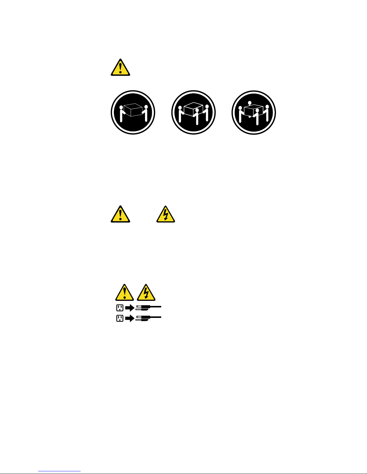
Statement 4
18 kg (37 lbs) 32 kg (70.5 lbs) 55 kg (121.2 lbs)
CAUTION:
Use safe practices when lifting.
Statement 5
CAUTION:
The power control button on the device and the power switch on the power supply do not
turn off the electrical current supplied to the device. The device also might have more than
one power cord. To remove all electrical current from the device, ensure that all power
cords are disconnected fro m the power source.
1
2
Page 10

viii IBM® xSeries 150: Installati on Guide
Page 11

© Copyright IBM Corp. 2000 ix
Contents
Safety . . . . . . . . . . . . . . . . . . . . . . . . . . . . . iii
Chapter 1.Introduction . . . . . . . . . . . . . . . . 1
Features and specifications . . . . . . . . . . . . . . . . . . . . . . . . 2
Notices used in this book. . . . . . . . . . . . . . . . . . . . . . . . . . 3
Chapter 2.Cabling the server . . . . . . . . . . . 5
Chapter 3.Starting the server . . . . . . . . . . . 7
Controls and indicators . . . . . . . . . . . . . . . . . . . . . . . . . . . 9
Operator information panel. . . . . . . . . . . . . . . . . . . . . . . 10
Chapter 4.Appliance Configuration
Programs . . . . . . . . . . . . . . . . . . . . . . . . . 13
Universal Manageability Services. . . . . . . . . . . . . . . . . . 13
System Requirements . . . . . . . . . . . . . . . . . . . . . . . . . 14
Starting UM Services. . . . . . . . . . . . . . . . . . . . . . . . . . 14
IBM Advanced Appliance Configuration Utility . . . . 15
The Advanced Appliance Configuration Utility Agent
16
The Advanced Appliance Configuration Utility
Console . . . . . . . . . . . . . . . . . . . . . . . . . . . . . . . . . . . . . . . . 16
Discovering xSeries Appliances . . . . . . . . . . . . . . 17
Using Families and Groups in the Tree View. . . 18
Launching UM Services. . . . . . . . . . . . . . . . . . . . . 21
Terminal Services Client. . . . . . . . . . . . . . . . . . . . . . . . . . 22
Chapter 5.Using the Recovery and
Supplementary CDs. . . . . . . . . . . . . . . . . 25
Using the Recovery Enablement Diskette and Recovery
CD . . . . . . . . . . . . . . . . . . . . . . . . . . . . . . . . . . . . . . . . . . . . 25
Using the Supplementary CD . . . . . . . . . . . . . . . . . . . . . 26
Chapter 6.Solving problems. . . . . . . . . . . 29
Diagnostic tools overview . . . . . . . . . . . . . . . . . . . . . . . . 29
POST beep code descriptions . . . . . . . . . . . . . . . . . . . . . 30
POST error messages . . . . . . . . . . . . . . . . . . . . . . . . . . . . 30
Troubleshooting chart. . . . . . . . . . . . . . . . . . . . . . . . . . . . 32
Appendix A. Rack Installation Instructions.
35
Appendix B. Product warranties and
notices . . . . . . . . . . . . . . . . . . . . . . . . . . . 39
Warranty Statements. . . . . . . . . . . . . . . . . . . . . . . . . . . . . 39
IBM Statement of Limited Warranty for United States,
Puerto Rico, and Canada (Part 1 - General Terms) . 39
IBM Statement of Warranty Worldwide except
Canada, Puerto Rico, Turkey, United States (Part 1 –
General Terms) . . . . . . . . . . . . . . . . . . . . . . . . . . . . . . . 42
Part 2 - Worldwide Country-Unique Terms. . . . . . . 45
End-User License Agreement: Microsoft Windows
Powered Operating System . . . . . . . . . . . . . . . . . . . . . . . 49
End-User License Agreement: Microsoft Windows
Services for NetWare Version 5.0. . . . . . . . . . . . . . . . . . . 52
Notices. . . . . . . . . . . . . . . . . . . . . . . . . . . . . . . . . . . . . . . . . 55
Edition Notice . . . . . . . . . . . . . . . . . . . . . . . . . . . . . . . . 55
Year 2000 readiness and instructions. . . . . . . . . . . . . 56
Trademarks . . . . . . . . . . . . . . . . . . . . . . . . . . . . . . . . . . 56
Important notes . . . . . . . . . . . . . . . . . . . . . . . . . . . . . . 57
Electronic emission notices . . . . . . . . . . . . . . . . . . . . . . . 57
Federal Communications Commission (FCC)
Statement. . . . . . . . . . . . . . . . . . . . . . . . . . . . . . . . . . . . 57
Industry Canada Class A emission compliance
statement . . . . . . . . . . . . . . . . . . . . . . . . . . . . . . . . . . . . 58
Australia and New Zealand Class A statement. . . . 58
United Kingdom telecommunications safety
requirement. . . . . . . . . . . . . . . . . . . . . . . . . . . . . . . . . . 58
European community directive conformance
statement . . . . . . . . . . . . . . . . . . . . . . . . . . . . . . . . . . . . 58
Taiwan electrical emission statement . . . . . . . . . . . . 59
Japanese Voluntary Control Council for Interference
(VCCI) statement . . . . . . . . . . . . . . . . . . . . . . . . . . . . . 59
Power cords . . . . . . . . . . . . . . . . . . . . . . . . . . . . . . . . . . . . 59
Index . . . . . . . . . . . . . . . . . . . . . . . . . . . . . . 61
Page 12

x IBM® xSeries 150: Installation Guide
Page 13

© Copyright IBM Corp. 2000 1
Chapter 1. Introduction
Thank you for pur c ha sin g an IBM
®
xSeries150 server . This Installation Guide
provides the information that is needed to:
• Set up and cable your server
• Start and configure your server
• Connect to and manage your server
Packaged with the Installation Guide are software CDs that can be used to reload the
network operating system (NOS), install additional software features, and install
device drivers.
Also included is an IBM xSeries Documentation CD, which provides detailed
information about your server.
Your server comes with a three-year limited warranty and 90-Day IBM Start Up
Support. If you have access to the World Wide Web, you can obtain up-to-date
information about your xSeries 150 model and other IBM server products at the
following World Wide Web address:
http://www.ibm.com/pc/us/netfinity/
For a rack model, refer to the Rack Installation Instructions provided with your server
for complete installation and removal instructions.
The server serial number is located on labels on the rear of the server and on the front
of the server below the bezel.
Note: Your server keys cannot be duplicated by locksmiths. If you lose them, order
replacement keys from the key manufacturer. The key serial number and
phone number of the manufacturer are on a tag attached to the keys.
Record your product information in this table.
Product name _____________________________________________
Machine type _____________________________________________
Model number _____________________________________________
Serial number _____________________________________________
Key serial number (tower model only) __________________________
Key manufacturer (tower model only) __________________________
Key phone number (tower model only) __________________________
Page 14

2 IBM® xSeries 150: Installation Guide
Features and specifications
Table 1 provides a summary of the features and specifications for your xSeries 150
server.
Table 1. Features and Specifications
Microprocessor:
• 1 or 2 Intel® Pentium® III
microprocessors with
MMX™ technology and
SIMD extensions, depend ing
on model
• 256 KB Level-2 cache (min.)
• Supports up to two
microprocessors
Memory:
• Standard: 256 MB or 1 GB,
depending on model
• Maximum: 4 GB
• Type: 133 MHz, ECC,
SDRAM, Registered DIMMs
• Slots: 4 dual inline slots
Drives standard:
• 3 or 6 Hard Disk Drives,
depending on model
• Diskette: 1.44 MB
• CD-ROM: 40X IDE
Expansion bays:
• Hot-swap: six slim high or
three half high
• Non-hot-swap: Three 5.25inch (one used by CD-ROM
drive)
PCI expansion slots:
• Three 33 MHz/6 4-b it
• Two 33 MHz/32-bit
Power supplies:
250 watt (115-230 Vac)
• Standard: One
• Maximum: Three, only with
optional power backplane
that enables multiple power
supplies and hotswappability
Video:
• S3 video controller (integrated on
system board)
• Compatible with SVGA and VGA
• 8 MB SDRAM video memory
Size (Rack Model 5U)
• Height: 220 mm (8.7 in.)
• Depth: 630 mm (24.8 in.)
• Width: 440 mm (17.3 in.)
• Weight: approximately 35.38 Kg (78
lb.) when fully configured
Size (Tower Model)
• Height: 440 mm (17.3 in.)
• Depth: 660 mm (26.0 in.)
• Width: 220 mm (8.7 in.)
• Weight: approximately 36.74 Kg (81
lb.) when fully configured
Integrated functions:
• Netfinity Advanced System
Management processor
• ServeRAID 4L/4H PCI adapter
• Dual channel Ultra3 SCSI controller
• One integrated 10BASE-T/100 BA SE-
TX AMD Ethernet controller
• 1 or 3 Netfinity 10/100 Ethernet
Adapter 2s, depending on model
• Two serial ports
• One parallel port
• Two Universal Serial Bus (USB) ports
• Keyboard port
• Mouse port
• Video port
Acoustical noise emissions:
• Sound power, idling: 6.0 bel
maximum
• Sound power, operating: 6.0 bel
maximum
• Sound pressure, operating: 45 dBa
maximum
Environment:
• Air temperature:
— Server on: 10 to 35 C
(50.0 to 95.0 F).
Altitude: 0 to 914 m
(2998.7 ft.)
— Server on: 10 to 32 C
(50.0 to 89.6 F).
Altitude: 914 m (2998.7
ft.) to 2133 m (6998.0 ft.)
— Server off: 10 to 43 C
(50.0 to 109.4 F).
Maximum altitude: 2133
m (6998.0 ft.)
• Humidity:
— Server on: 8% to 80%
— Server off: 8% to 80%
Heat output:
Approximate heat output in British
Thermal Units (BTU) per hour
• Minimum configuration: 683
BTU (200 watts)
• Maximum configuration:
2048 BTU (600 watts)
Electrical input:
• Sine-wave input (50-60 Hz)
required
• Input voltage low range:
— Minimum: 100 V ac
— Maximum: 127 V ac
• Input voltage high range:
— Minimum: 200 V ac
— Maximum: 240 V ac
• Input kilovolt-amperes
(kVA) approximately:
— Minimum: 0.08 kVA
— Maximum: 0.52 kVA
Page 15

Chapter 1. Introduction 3
Notices used in this book
This information product contains notices that relate to a specific topic. The Caution
and Danger notices also appear in the multilingual safety booklet that came with your
xSeries product. Each notice is numbered for easy reference to the corresponding
notices in the safety booklet.
The notice definitions are as follows:
• Notes:These notices provide important tips, guidance, or advice.
• Attention:These notices indicate possible damage to programs, devices, or data.
An attention notice is placed just before the instruction or situation in which
damage could occur.
• Caution:These notices indicate situations that can be potentially hazardous to
you. A caution notice is placed just before descriptions of potentially hazardous
procedure steps or situations.
• Danger: These notices indicate situations that can be potentially lethal or
extremely hazardous to you. A danger notice is placed just before descriptions of
potentially lethal or extremely hazardous procedure steps or situations.
Page 16

4 IBM® xSeries 150: Installation Guide
Page 17
© Copyright IBM Corp. 2000 5
Chapter 2. Cabling the server
When you cable the server, be sure to route the power cable through the cablerestraint bracket on the rear of the server. Because your xSeries 150 is a "headless"
server, you will not need to connect a mouse or keyboard cable when cabling your
server. You wil l only need to connect the power cable and network cables.
Before cabling the server, you must first unpack the appliance server and place it in
the location where it will be installed or, if you are installing a rack-mounted model,
install the appliance server in a rack. For more informatio n on how to install a rackmounted server in a rack, see “Appendix A. Rack Installation Instructions,” on page
35.
Notes:
1. If you plan to use the IBM Advanced Appliance Conf iguration Utility to
configure and manage your appliance, be sure to connect the built-in Ethernet
connector to the same physical network as your sys tems management console.
2. The illustrations in this document might differ slightly from your hardware.
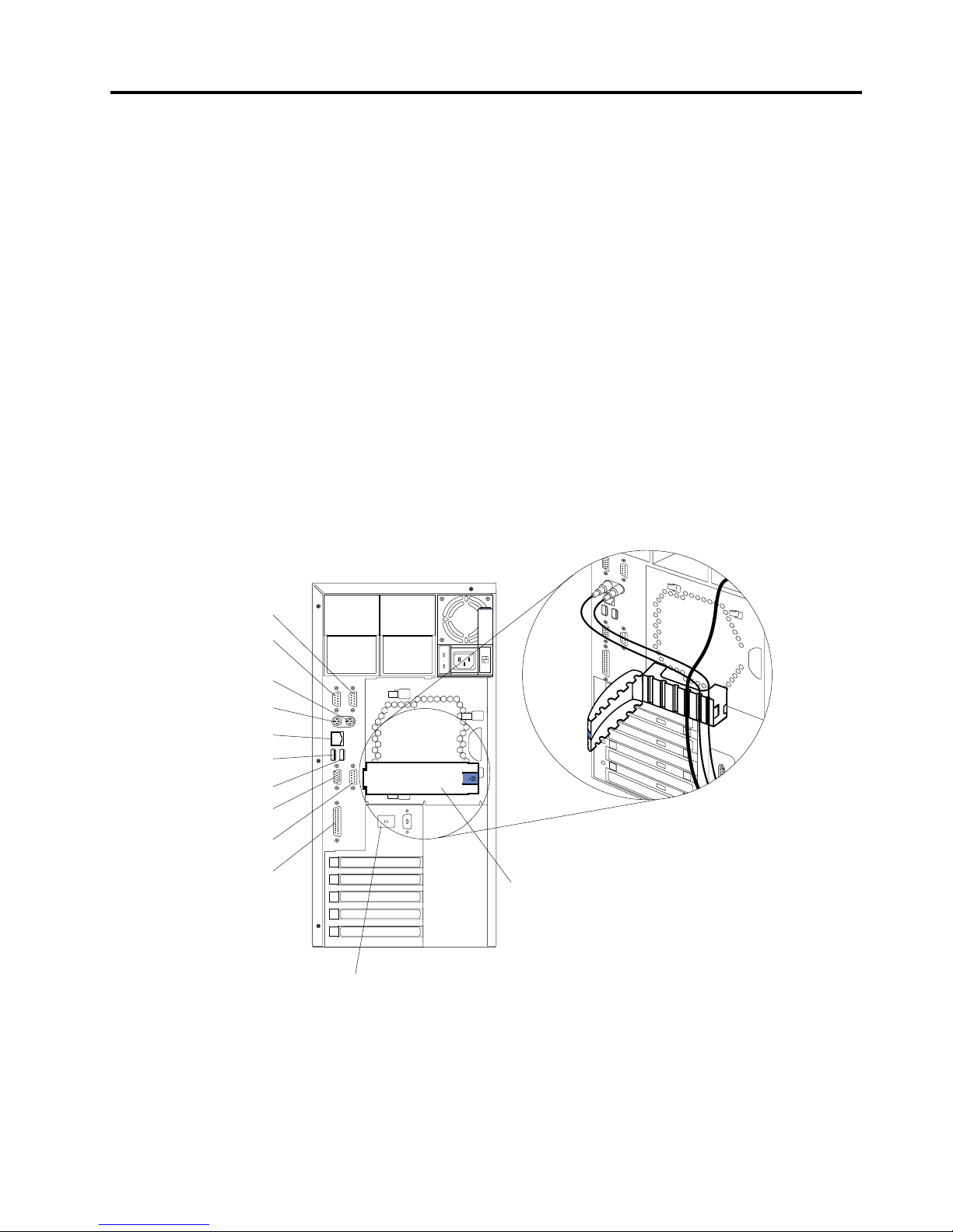
Cabling the rear of the server
Note: The Management connector is dedicated for use by the Advanced System
Management processor.
Serial A
Serial B
Mouse
Keyboard
Ethernet
USB 1
USB 2
Video
Management
Parallel
Advanced System
Management
Interconnect knockout
Cable-restraint
bracket
Page 18
6 IBM® xSeries 150: Installation Guide
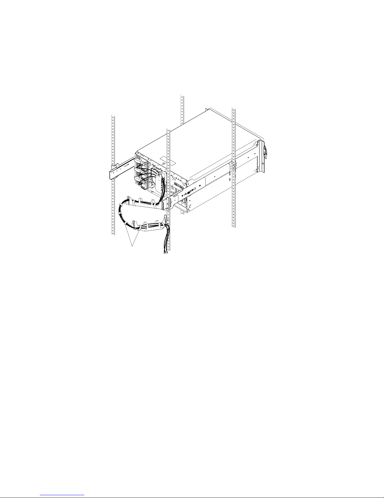
Additionally, for rack models, be sure to route all the cables through the cablemanagement assembly on the rack (see the following illustration).
Routing cables through cable-management assembly
For more information on installing your xSeries 150 in a rack, see “Appendix A. Rack
Installation Instructions,” on page 35.
Cable straps
Page 19
© Copyright IBM Corp. 2000 7
Chapter 3. Starting the server
After you plug the power cord of your server into the power supply and an electrical
outlet, the server can start in several ways:
• You can press the Power control button on the front of the server to start the
server.
Note: After you plug the power cord of your server into an electrical outlet,
wait approximately 20 seconds bef ore pressing the Power control
button. During this time, the system-management processor is
initializing and the Power Control button does not respond.
• If the server is turned on, a power failure occurs, and unattended-start mode is
enabled in the Configuration/Setup utilit y program, the server wi ll start
automatically when power is restored.
• If AC power is present, the server is off, and the wake-up feature is enabled in
the Configuration/Setup utility program , the wake-up feature will turn on the
server at the set time.
• If AC power is present, the server is off, and ring signal detect is enabled in the
Configuration/Setup utility program, you can turn on the server by telephone
input.
• The Netfinity Advanced System Management Processor also can turn on the
server.
Statement 5
CAUTION:
The power control button on the device and the power switch on the power supply do not
turn off the electrical current supplied to the device. The device also might have more than
one power cord. To remove all electrical current from the device, ensure that all power
cords are disconnected fro m the power source.
The first time you start your server, a series of configuration and system
preparation programs that finish configuring the NOS are run
automatically. These programs must finish running before you use any
included applications (such as the IBM Advanced Appliance
Configuration Utility or the Terminal Services Client) to connect to or
configure your xSeries 150. Do not connect to or configure the xSeries 150
for at least 15 minutes after the initial system start. This notice applies
only to the first time the xSeries 150 is started.
Important
Page 20

8 IBM® xSeries 150: Installation Guide
You can turn off the server as follows:
• You can press the Power control button on the front of the server. This starts an
orderly shutdown of the operating system, if this feature is supported by your
operating system, and places the server in standby mode.
Note: After turning off the server, wait at least 5 seconds before you press the
Power control button to power the server on again.
• You can press and hold the Power control button for more than 4 seconds to
cause an immediate shutdown of the server and place the server in standby
mode. You can use this feature if the operating system ceases to function.
• You can disconnect the server power cords from the electrical outlets to shut off
all power to the server.
Note: Wait about 15 seconds after disconnecting the power cords for your
system to stop running. Watch for the Power-on light on the operator
information panel to stop blink ing.
Statement 5
1
2
Page 21
Chapter 3. Starting the server 9
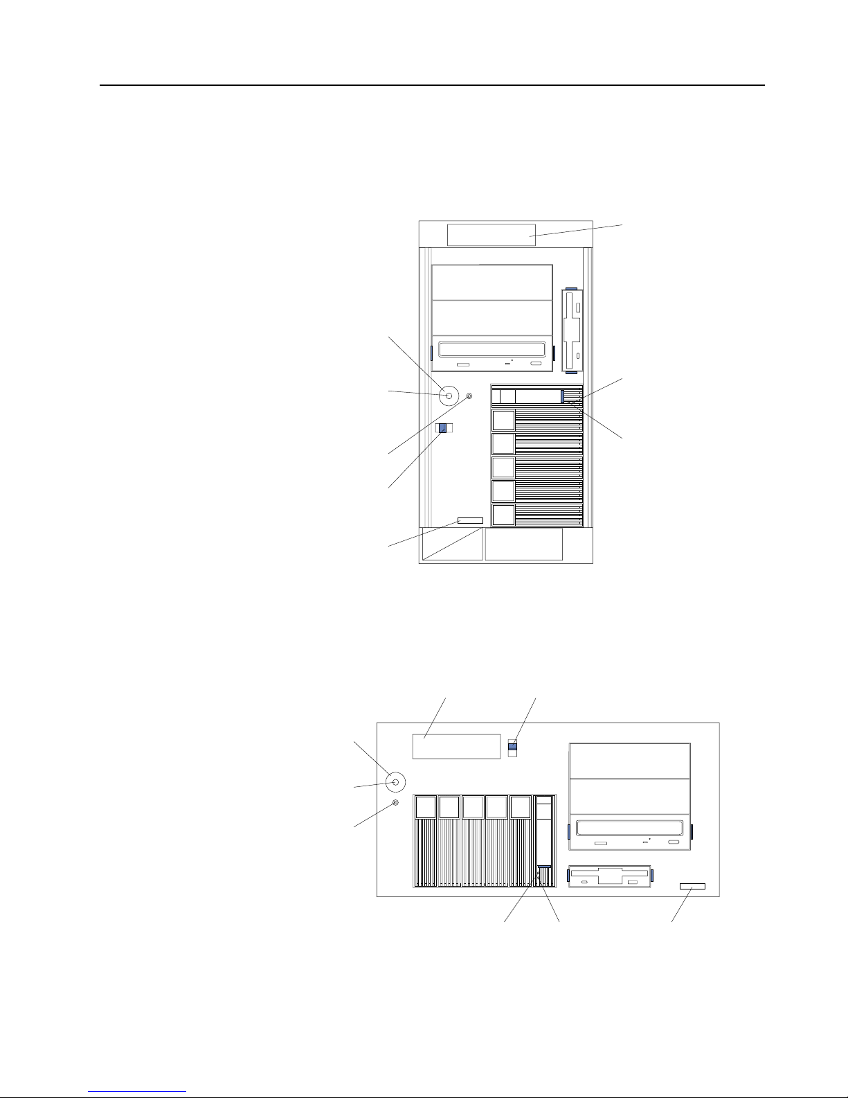
Controls and indicators
The following illustrations show the controls and indicators on the front of the server.
Power control button: Press this button to manually turn the server on or off.
Tower model
Rack model
Hard disk
drive activity
light (green)
Hard disk
drive status
light (amber)
Reset
button
Power
control
button
Power control
button shield
(if installed)
Cover
release
latch
Serial
number
Operator
information
panel
Hard disk
drive activity
light (green)
Hard disk
drive status
light (amber)
Reset button
Power control
button
Cover
release
latch
Operator
information
panel
Power control
button shield
(if installed)
Serial
number
Page 22
10 IBM® xSeries 150: Ins ta llation Guide
Power control button shield: You can install this circular disk over the power control
button to prevent accidental manual power-off. This disk is pro vided with your
server.
Reset button:Press this button to reset the server and run the power-on self-test
(POST).
Operator information panel:The lights on this panel give status information for your
server.
Cover release latch:Slide this lever to release the cover.
Serial number:This number uniquely identifies your server.
Hard disk drive status light: Each of the hot-swap drives has a hard disk drive status
light. When this amber light is on continuously, the drive has failed.
Hard disk drive activity light: Each of the hot-swap driv es has a hard disk drive
activity light. When this green light is flashin g, the controller is accessing the drive.
If a ServeRAID adapter is installed and this light flashes slowly (one flash per second),
the drive is being rebuilt. When the light flashes rapidly (three flashes per second),
the controller is identifying the drive.
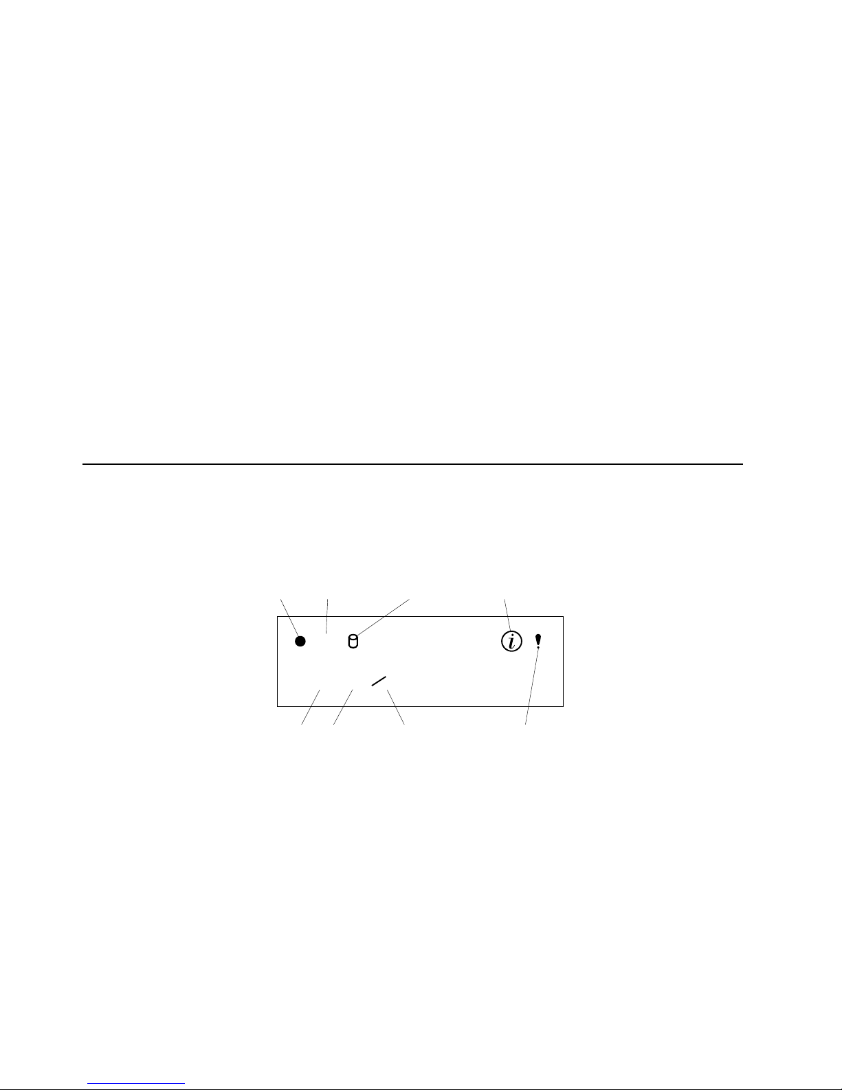
Operator information panel
The following illustration shows the location of the status lights on the operator
information panel on the front of the server (see “Controls and indicators” on page 9).
Power-on light
This green LED lights when system power is present in the server. When this
light flashes, the server is in standby mode (the system power supply is
turned off and AC current is present). If this light is not on, the power cord is
not connected, the power supply has failed, or this LED has fail ed.
POST complete light
This green LED lights when the server completes the power-on self-test
(POST) without any errors.
SCSI hard disk drive in-use light
This green LED lights when there is activity on a hard disk drive.
OK
100
MB
LINK
OK
TX
RX
Power-on
light
POST
complete light
SCSI hard
disk drive
in-use light
Information
light
System
error light
Ethernet
speed light
Ethernet link
status light
Ethernet transmit/
receive activity light
Page 23

Chapter 3. St arting the server 11
Information light
This amber LED lights when the information log contains information about
certain conditions in your server that might affect performance. For example,
the light will be on if your server has multiple power supplies and does not
have redundant power. An LED on the diagnostic panel on the system board
will also be on.
System error light
This amber LED lights when a system error occurs. An LED on the
diagnostic panel on the system board will also be on to further isolate the
error. Refer to the "Problem solving" section of the User’s Reference on the IBM
xSeries Documentation CD for detailed information on using the diagnostic
panel (light path diagnostics).
Ethernet speed light
This green LED lights when the Ethernet LAN speed is 100 Mbps.
Ethernet link status light
This green LED lights when there is an active connection on the Ethernet
port.
Ethernet transmit/receive activ it y light
This green LED lights when there is transmit or receive activity to or from the
server.
Page 24

12 IBM® xSeries 150: Ins ta llation Guide
Page 25

© Copyright IBM Corp. 2000 13
Chapter 4. Appliance Configuration Programs
Your xSeries appliance server comes with programs that can be used to configure,
manage, and maintain your applia nce server. These configuration programs include:
• Universal Manageability Services
Universal Manageability Services (UM Services) provides point-to-point remote
management of client systems through a Web browser window. Use UM
Services to:
— Learn detailed inventory information about your computers, including
operating system, memory, network cards and hardware.
— Trac k your computers proactively with features such as power
management, event log, and system monito r capa bilities.
— Upwardly integrate with Tivoli Enterprise, Tivoli NetView, Computer
Associates Unicenter, Microsoft SMS, and Intel LANDesk Management
Suite.
• IBM Advanced Appliance Configuration Utility
The Advanced Appliance Configuration Utility aids in setting up and
reconfiguring the network configuration o n your appliance servers. The
Advanced Appliance Configuration Utility agent, preinstalled on your IBM
xSeries appliance, works with the Advanced Appliance Configuration Utility
console to automatically detect the presence of appliances on the network. Once
the appliance server is detected by the Advanced Appliance Configuration
Utility console, use the Advanced Appliance Configuration Utility to set up and
manage the appliance’s network configuration, including assigning the IP
address, default gateway, network mask, and DNS server to be used by the
appliance. You can also use the Advanced Appliance Configuration Utility to
start UM Services on the appliance, enabling you to perform more advanced
systems management tasks.
• Terminal Services Client
Because your xSeries appliance server is installed in a "headless" environment
(meaning that the appliance does not have a mouse or keyboard attached to it),
you must perform systems management tasks on the appliance from a remote
systems management console. The Terminal Services Client, when installed on a
workstation that is attached to the same network as the appliance server, enables
remote administration of the appliance.
Information about each of these appliance configuration programs follows.
Universal Manageability Services
Universal Manageability Services (UM Services) is a suite of graphical user interfaces
(GUIs) that enhances the local or remote administration, monitoring, and
maintenance of IBM systems. UM Services is a lightweight client that resides on each
managed computer system. With UM S ervices, a client-system user or remote s ystems
administrator can use a supported Web browser or the Microsoft Management
Console (MMC) and UM Services Web console support to inventory, monitor, and
troubleshoot IBM systems on which UM Services is in stalled.
This "point-to-point" systems-management approach, in which a system-management
administrator uses a Web browser to connect directly to a remote client system, can be
Page 26

14 IBM® xSeries 150: Ins ta llation Guide
used to enhance support and to enable systems administrators to effectively maintain
IBM systems without requiring them to install additional systems-management
software on their administrator console.
In addition to point-to-point systems-management support, UM Services also
includes support for UM Services Upward Integration Modules (Aims) . Aims enable
systems-management professionals who use any supporte d systems-management
platform (including Tivoli Enterprise, CA Unicenter TNG Framework, and Microsoft
Systems Management Server (SMS) to integrate portions of UM Services into their
systems-management console. Because it was designed to use industry-standard
information gathering techno logies and messaging protocols (including Com mon
Information Model (CIM), Desktop Mana gement Interface (DMI), and Simple
Network Management Protocol (SNMP), UM Services adds value to any of these
supported workgroup or enterprise system-management platforms.
Complete documentation on how to use UM Services is included on the IBM xSeries
150 Documentation CD.
System Requirements
The UM Services client is preinstalled o n your xSeries appliance server. However, you
must have a supported web browser installed on your systems management console.
Supported browsers include:
• Microsoft Internet Explorer 4.01 or later
Notes:
1. If you are using Internet Explorer 5.x, you must install the optional Java
Virtual Machine (VM) support to access a client system running UM
Services.
2. If you are using Internet Explorer and you reinstall Internet Explorer after
installing UM Services you must reapply the Microsoft VM update. The UM
Services client requires Microsoft VM Build 3165 or later. Download the
latest Microsoft VM from
http://www.microsoft.com/java
• Netscape Navigator or Netscape Communicator 4.5 or later
• Microsoft Management Console (MMC) 1.1 or later
Note: If you install UM Services before you install MMC 1.1 o r later you will
not have an icon for Microsoft Management Console in the IBM
Universal Manageability Services section of your Start Menu.
Starting UM Services
Before you can use UM Services, you must configure the network se ttings (such as IP
address, subnet mask, and so forth) on your xSeries appliance server. You can use IBM
Advanced Appliance Configuration Utility or Windows Terminal Services Client to
configure the network setting remotely, or you can attach a keyboard and mouse to
your appliance server and configure the Network settings using the Windows Control
Panel. Once you have configured the network settings for your appliance, you are
ready to use UM Services.
To start UM Services:
1. Start your web browser and then type in the Address or Location field of the
browser
http://ip_address:1411
where ip_address is IP address of the appliance server, and then press Enter.
Page 27

Chapter 4. Appliance Configuration Programs 15
Or, type
htp://ibm-xxxxxxx:1411
where xxxxxxx is the IBM serial number of the appliance, and then Enter.
2. A user login window appears. Type Administrator in the Username field, and
type password for the Password field. You can leave domain blank. Make sure
the "Save this password in your password list" checkbox is not checked, and then
click OK.
Note: The first time you connect you may be prompted to install XML a nd
Swing components. Follow the on-screen instructions to install these
components, then close and restart Internet Explorer before you proceed.
3. You are now connected to the appliance via UMS. Complete documentation on
how to use UM Services is included on the IBM xSeries 150 Documentation CD. In
additional to the standard UM Services functionality, your xSeries applaince
includes additional functionality, available from the Applainces tab in the UM
Services console. The default view when you connect to your appliance the
Terminal Services panel, which displays a Windows 2000 Terminal Services Web
Connection page. To connect to the appliance to manage it as though you were
running Terminal Services Client from your desktop:
a. Type in the IP address field the IP Address of the server (seen in upper left
hand corner of left UMS panel), or enter IBM-{xxxxxxx} (where xxxxxxx is the
serial number that appears on the front of the appliance).
b. Choose a size other than full screen which the Appliance desktop will appear
in, then click Connect to start the Te rminal Services Client session on the
appliance. A user login widow appears.
c. Log into the appliance. Type Administrator in the Username field, type pass
word in the password field, and then click OK to log in. Once you have
logged in, you can begin using Terminal Services Cleint to configure and
manage your appliance.
Note: To ensure system security, use Windows Powered to change th e
Administrator password from "password" to something else. Once
you do, or if you create another user in the Administrator group in
the future, use your new username/password combination instead of
the default username/password combination.
IBM Advanced Appliance Configuration Utility
The IBM Advanced Appliance Configurat ion Utility aids in setting up and
reconfiguring the network configuration on yo ur xSeries appliance servers. The
Advanced Appliance Configuration U tility agent, preinstalled on your IBM xSeries
appliance, works with the Advanced Appliance Configuration Utility console, a Javabased application that is installed on a network-attached system that will be used as a
systems management console that enables you to automatically detect the presence of
xSeries appliances on the network. Once the xSeries appliance is detected by the
Advanced Appliance Configuration Utility console, use the Advanced Appliance
Configuration Utility to set up and manage the appliance’s network configuration,
including assigning the IP address, defa ult gateway, network ma sk, and DNS server
to be used by the appliance. You can also use the Advanced Appliance Configuration
Utility to start Universal Manageab ility Services (UM Services) on the appliance,
enabling you to perform more advanced systems management tasks.
Networks that are not currently running DHCP servers will find the Advanced
Appliance Configuration Utility particularly useful for automatically configu ring
network settings for newly added applian c e servers. However, networks with DHCP
servers will benefit from using the Advanced Applianc e Configuration Utility as it
enables the systems administrator to reserve and assign the appliance IP address in an
Page 28

16 IBM® xSeries 150: Ins ta llation Guide
orderly, automated fashion. Even if the customer decides to use DHCP and does not
choose to reserve an IP address for the appliance, the Advanced Appliance
Configuration Utility can still be used to discover appliances and to start UM Services
web-based systems manage ment.
Notes:
1. The Advanced Appliance Configuration configures and reports the TCP/IP
settings of the first adapter on each appliance server only. The first adapter is
typically the built-in Ethernet controller. Be sure to connect the built-in Ethernet
connector to the same physical network as yo ur systems management console.
2. The Advanced Appliance Configuration Utility must be running to configure
newly installed appliance servers automatically.
3. The system running the Advanced Appliance Configuration Utility console
automatically maintains a copy of its database (ServerConfiguration.dat) in the
Advanced Appliance Configuration Station installation directory. To remove
previous configuration data, close the Advanced Appliance Configuration Utility,
delete this file, and then restart the utility. This deletes all previously configured
Families. However, the Advanced Appliance Configuration Utility will discover
connected xSeries appliances and their network settings.
The Advanced Appliance Configuration Utility Agent
Once your appliance is connected to your network, the Advanced Appliance
Configuration Utility agent automa tically reports the appliance’s MAC address (of
the first NIC only), serial number, type of appliance, and whether DHCP in use by the
appliance or not. Furthermore, it will report the hostname, primary IP address, subnet
mask, primary DNS address, and primary gateway addres s if these are config ur ed on
the system.
The Advanced Appliance Configuration Utility agent is preinstalled on your xSeries
appliance.
Note: The Advanced Appliance Configuration Utility agent periodically broadcasts
the appliance server IP settings. To prevent the service from broadcasting this
data periodically, stop the iaaconfig service.
The Advanced Appliance Configuration Utility Console
The Advanced Appliance Configuration Utility Console is a Java application that you
install on one system in your network that will be used as a systems management
console. For information on how to install the Advanced Appliance Configuration
Utility Console, see “Using the Supplementary CD” on page 26.
Note: Do not install the Advanced Appliance Configuration Utility Conso le on
more than one systems management console.
The Advanced Appliance Configuration Utility Console enables you to:
• Automatically discover xSeries appliance servers that run the Advanced
Appliance Configuration Utility agen t and are attached to the same physical
subnet as the Advanced Appliance Confi guration Utility Console.
When you start the Advanced Appliance Configuration Utility Console it
automatically detects all applian c e servers on yo ur physical subnet that are
running the Advanced Appliance Configurati on Utility agent.
• Use a simple, GUI-based application to configure the appliance servers network
settings.
Use the Advanced Appliance Configuration Utility to assign IP addresses, DNS
and gateway server addresse s, subnet masks, hostnames, and more.
Page 29

Chapter 4. Appliance Configuration Programs 17
• Automatically group discovered appliances into function-specific Families.
Appliances are added to a Family based on the appliance type. Appliances
running different operating systems, but which perform the same function,
appear in the same Family.
• Start UM Services web-based systems management console.
Launch UM Services on your appliance servers and perform advanced systems
management tasks on a selected appliance server with a single mouse click.
The Advanced Appliance Configuration Utility Console is divided into two panes:
• The Tree View Pane
The Tree View Pane, located on the left side of the Advanced Appliance
Configuration Utility Console window, presents a list of all discovered xSeries
appliances and includes any Families you have previously defined. The Tree
View Pane also includes groups for appliances that do not fit any of the defined
Families, that were not configured using the Advanced Appliance Configuration
Utility, or that ha ve IP addresses that conflict with other devices on your
network. When you click on any item in the Tree View information about that
item (and any items which are nested below that item in the tree view)
information about the selected item appears in the Informa tion Pane.
• The Information Pane
The Information Pane, located at the right side of the Advanced Appliance
Configuration Utility Console, displa ys information about the item that is
currently selected in the Tree View Pane. The information that appears in the
Information Pane varies depending on the item that is selected. For example, if
you select the All Appliances item from the Tree View Pane, the Information
Pane displays configuration information (IP settings, hostname, serial number,
and so forth) about all of the xSeries appliances that have been discovered by the
Advanced Appliance Configuration U tility Console. However, if you select a
Family, the Information Pane displays information about the Family settings for
the selected Family.
The Advanced Appliance Configuration Utility Console also features the following
menus:
• File
Use the selections available form the File menu to import or export the
Advanced Appliance Configuration Utility Console configuration data , to
rescan the network, or to exit the program.
• Family Use the selections available from the Family menu to add or delete
Families, or to move Families up or down in the tree view.
• Appliance Use the selections available form the Appliance menu to remove a
previously discovered appliance from a Family or group, and to add an
appliance to the first matching Family in the tree view.
• Help
Use the Help menu to display product information.
Discovering xSeries Appliances
Any xSeries appliance server that is running and is connected to the sa me subnet as
the system running the Advanced Appliance Configuration Utility console is
automatically discovered when you start the Advanced Appliance Configuration
Utility console. Discovered appliances appear in the Advanc ed Appl iance
Configuration Utility console tree view (found in the left pane of the Advanced
Appliance Configuration Utility console window). Each appliance will appear in two
locations in the tree view:
Page 30

18 IBM® xSeries 150: Ins ta llation Guide
1. Every discovered appliance is listed in the tree view under All Appliances.
2. Each discovered appliance will also appear in one of the following portions of the
tree view:
• In a Family
If the discovered appliance fits the requirements of a Family, it will
automatically appear as part of a Family.
Note: If a discovered appliance fits the requirements of more than one
Family, it is automatically added to the first appropriate Family that
is listed in the tree view, starting from the top of the tree. For
information on how to move appliances between families, see
“Using Families and Groups in the Tree View”.
• In the Orphaned Appliances group
If the discovered appliance does not fit a previously configured Family, it is
placed in the Orphaned Appliances grou p .
• In the Orphaned Externally Configured Appliances group
Appliances that are running the Advanced Appliance Configuration Utility
agent, but that have a network configuration that wa s not set by the
Advanced Appliance Configuration Utility agent or console, will appear in
the Orphaned Externally Configured Appliances group. If an appliance is
contained in the Orphaned Externally Configured Appliances group you
can use the Adopt By First Matching Family f unction to add it to a
previously defined Family. For more information, see “Using the Adopt by
First Matching Family Fun c tion” on page 21.
Using Families and Groups in the Tree View
Families are important elements of the Advanced Appl iance Configuration Utility.
They specify the parameters the Advanced Appliance Con figuration Utility uses to
automatically categorize discovered appliances and to con fi gure them with the
appropriate network settings. Family rules are defined solely by appliance type or
purpose. Each Family can contain only one type of appliance. The only way to
automatically apply predetermined networ k settings to newly installed and
discovered appliance servers is to create and use Families.
Appliance servers that match the rules criteria for a Family group can be
automatically configured to use predefined networ k settings. A Family can be
configured to allow appliances to use DHCP to configure their IP settings, or can be
defined to automatically assign IP settings (such as primary gateway and DNS server
addresses, assigning an IP address from a specified IP address range, and specifying a
subnet mask). Host names for discovered appliances can also be defined so that they
are allocated using either a Prefix or Serial Number.
The Advanced Appliance Configuration Utility is not the only way to configure
network settings. For example, network settings can be configured using Terminal
Services for Windows or by attaching a keyboard and mouse to the appliance and
using Windows Control Panel on the server. If the appliance network settings have
been configured by a method other than using the Advanced Appliance
Configuration Utility the appliance will be discovered by the Advanced Appliance
Configuration Utility and it will be added to an appropriate Family, if one exists.
Appliances that have been configured using a method other than the Advanced
Appliance Configuration Utility for which no appropriate family exists will appear in
the Orphaned Externally Configured Appliances group.
The Tree View Panel contains the following items:
• All Appliances Every discovered appliance is listed in the tree view under All
Appliances.
Page 31

Chapter 4. Appliance Configuration Programs 19
• Families
The Families group in the Tree View Pane shows all Families that have been
defined, with appliance servers that have already been assigned to each Family
nested beneath the Family name in the tree view. Families are defined by
appliance purpose so all appliances that appear in a given family are of the same
type. If you select a Family from the Tree View Pane a description of the Family
and the rules that are used to define the selected Family are displayed in the
Information Pane. If you select an appl iance server from a Family in the Tree
View Pane, the selected appliance network settings are displayed in the
Information Pane.
If you are not using DHCP, the Advanced Appliance Configuration Utility
automatically assigns one IP address per appliance server, using available
addresses within the range defined in the Family rules. When a Family’s IP
address range has been exhausted, the Advanced Appliance Configuration
Utility automatically searches for other Fam ilies that have rules matching the
appliance server being configured. If a matching Family with an available
address is found, the server will automatically be assigned to the Family that has
available IP addresses. This enables you to define multiple Families, each of
which uses a range of non-contiguous IP address ranges.
When an appliance is discovered on the network, the Advanced Appliance
Configuration Utility automa tically searches all previously defined Families,
starting with the first Family listed in the Families tree view and moving
downward. Appliances are automatically added to the first defined Family that
matches the appliance purpose. Therefore, the order in which Families appear is
important. To adjust this search order, right click on a Family and then select
Move Up or Move Down to adjust its position within the Families list.
• Orphaned Appliances
Any discovered appliance servers that have been configured using the
Advanced Appliance Configuration Utility but that do not meet the rules for
any existing Family are automatically added to the Orphaned Appliances group.
• Orphaned Externally Configured Appliances
Any discovered appliance server that has been configured without using the
Advanced Appliance Configuration Utility tool and that does not meet the rules
for any existing Family is automatically added to the Orphaned Externally
Configured Appliances group. Appliance servers configured without the
Advanced Appliance Configuration Utility that meet the rules for any existing
Family are automatically added to the matching Family. To add an Orphaned
Externally configured Appliance to an appropriate Family that was created after
the orphaned appliance was discovered, right-click on the orphaned appliance
and select Adopt by First Matching Family. For more information, see “Using
the Adopt by First Matching Family Function” on page 21.
Note: The Advanced Appliance Configuration U tility will not change
manually configured network setti ngs of discovered appliance servers.
If the manually configured IP and Subnet addresses fit an existing
Family, the Advanced Appliance Configuration Utility will plac e tha t
appliance server into that Family, but will not change any other settings
(such as Host Name or DNS or Gateway add resses) .
• Conflicting Network Addresses
Any discovered appliance server that has the same IP address as a previously
discovered appliance server will be listed in the Conflicting Network Addresses
group.
Creating a Family: To create a Family:
1. Select Create Family from the Family menu.
Page 32

20 IBM® xSeries 150: Ins ta llation Guide
The Advanced Appliance Configuration Utility Family Setup window appears.
2. Select the Appliance Family Rules.
The Appliance Family Rules determine what purpose an appliance must serve to
be included in the Family. You can select one of the following values:
• IBM xSeries 150
• IBM xSeries 130 and 135
3. Specify a Family name.
Type in the Family Name field that name that will be used for this Family.
4. Specify network resources to be used by members of the Family.
You can use the Advanced Appliance Configuration Utility to assign network
resources for members of this Family, to you can use a DHCP server to assign
network resources.
• To use the Advanced Appliance Configuration Utility to assign network
resources, uncheck the Use DHCP checkbox and fill in the following fields:
Min IP Address
The lowest IP address in a range of IP addresses that can be
assigned to an appliance that is a member of this Family
Max IP Address
The highest IP address in a range of IP addresses that can be
assigned to an appliance that is a member of this Family
Subnet Mask The subnet mask value that will be used by appliances that
are members of this Family
Default Gateway
The IP address of the default gateway that will be used by
appliances that are members of this Family (optional)
DNS The IP address of the Domain Name Server that will be used by
appliances that are members of this Family (optional)
• To use a DHCP server to assign network resources, check the Use DHCP
checkbox. This will allow a DHCP server on your network to assign an IP
address and subnet mask and to specify the default gateway address and
address of the Domain Name Server that will be used by appliances that are
members of this Family.
5. Select a Host Name Allocation Type.
The Host Name Allocation Type enables you to automatically specify a specific
Host Name that members of this Family will use. You can select one of the
following Host Name Allocation Types:
No Allocation
No preconfigured host name format will be assigned to appliances that
are members of this family.
Use Serial Number
The Serial Number of the discovered appliance will be used as a host
name for the appliance.
Use Prefix Name
A user-specified prefix, along with an incremental number for each
appliance, will be used for the host name of each appliance that is a
member of this Family. Type the desired prefix in the Host Name Prefix
field.
6. Click OK to save this Family.
Page 33

Chapter 4. Appliance Configuration Programs 21
Removing Appliances from Families: Use the Remove Appliance to delete an
appliance from the Advanced Appliance Configuration Utility console database.
Removing an appliance that is no longer in use allows the IP address that was
assigned to the appliance to be allocated to another appliance. You can also removing
an appliance from a family and then Rescan the network to add it to an appropriate
Family that appears higher in the Tree View pane.
To remove an appliance, right-click on the appliance, and then select Remove
Appliance from the pop-up menu.
• If the Advanced Appliance Configuration Utility is unable to communicate with
the selected appliance (because, for example, it has been removed from the
network or has failed) the appliance is removed immediately.
• If the Advanced Appliance Configuration Utility is able to communicate with
the selected appliance you will be asked to confirm removal of the appliance
before the appliance removal task is completed. This helps prevent accidental
removal of an active and functional appliance.
Using the Adopt by First Matching Family Function: Use the Adopt by First
Matching Family function to:
• Add an Orphaned Externally Configured Appliance to an appropriate Family.
Appliances that have been configured without using the Advanced Appliance
Configuration Utility tool and that do not meet the rules for any existing Family
are automatically added to the Orphaned Externally Configured Appliances
group. If, after the orphaned appliance is discovered, you create a Family that is
appropriate for the orphaned appliance, right-click on the orphaned appliance
and select Adopt by First Matching Family to move the appliance from the
Orphaned Externally Configured Appliances group to the newly created Family.
• Move an appliance from one Family to another appropriate Family that occurs
higher in the list of previously defined Families. If there is more than one
appropriate Family for a newly discovered appliance, it automatically appears
in the first appropriate Family in the list of Families. If you want to move a
discovered appliance from one appropriate Family to another appropriate
Family:
1. Right-click on the Family that you want the appliance moved to.
2. Select Move Up in List to move the selected Family up in the list of families.
Repeat steps 1 and 2 until the Family that you want to add the appliance to
appears above the Family that currently contains the appliance.
3. Right-click on the appliance that you want to move to another Family and
then select Adopt by First Matching Family.
Launching UM Services
You can use the Advanced Appliance Configuration Utility to quickly and easily
launch UM Services on your xSeries appliances.
Note: The selected appliance server must be running Universal Manageability (UM)
Services as a UM Services client. Also, the systems management console (the
system that is running the Advanced Appliance Configuration Utility
Console) must use a web browser that is supported for use with UM Services,
and if you have never used UM Services from this system previously you will
need to install several plug-ins before proceeding. If you are using an
unsupported browser, or if your browser does not have the necessary plugins, you will be notified when you attempt to launch UM Services on the
appliance. For more information on UM Services, see the fo llowing web site:
http://www.pc.ibm.com/ww/software/applications/ums/library.html
Page 34

22 IBM® xSeries 150: Ins ta llation Guide
T o use the Advanced Appliance Configuration Utility Console to start UM Services on
an appliance:
1. Click on the appliance in the Advanced Appliance Configuration Utility Console
Tree View Pane.
When you select the appliance from the tree vie information about the selected
appliance appears in the Information Pa ne. A Start Web-Based Management
button appears as well.
2. Click Start Web-Based Management.
Your default web browser starts, loading the UM Services console automatically.
3. Log on to the UM Services console. Refer to step 2 on page 15 for proper login
instruction.
For more information on using UM Services to manage your appliances, see the
Universal Manageability Services User’s Guide, included on your IBM xSeries 150
Documentation CD.
Terminal Services Client
To install the T erminal Services Client on the remote workstation and connect to your
xSeries appliance server:
1. Insert the Supplementary CD into the workstation CD-ROM drive.
2. Click Start-> Run.
3. In the Open field, type (with quotes)
"x:\Terminal Services Client\Disk 1\setup.exe"
where x is the drive letter assigned to the CD-ROM drive. Then click OK to begin
the Terminal Services Client Setup program.
4. Accept the defaults in each window that opens or refer to the Microsoft Windows
documentation for more instructions. When the Terminal Services Client Setup
program is completed proceed to the next step.
5. Check the workstation network TCP/IP protocol configuration settings.
The IP address used by the workstation must be obtained automatically. If the
network interface card for the workstation is configured to obtain an IP address
automatically you can proceed to the next step. However, if the network interface
card for the workstation is configured to use a static IP address you must set the
IP Address and Subnet mask properties as follows:
a. Set the IP address.
If the workstation’s network interface card is configured to use a static IP
address you must configure it to obtain an IP address automatically.
b. Set the Subnet mask to: 255.255.0.0
Notes:
a. Y ou might be prompted to restart the workstation after you have changed the
configuration.
b. Do not be concerned if you do not have a DHCP server on your network. This
configuration automatically a ssigns an unused IP address to the workstatio n
that is on the same subnet as the xSeries appliance servers attached to the
LAN.
c. If you are not certain how to check the workstation network TCP/IP protocol
configuration settings refer to the Microsoft Windows documentation tha t
came with your workstation f or network configuration instructions.
Page 35

Chapter 4. Appliance Configuration Programs 23
6. Connect to the xSeries 150 Appliance using the Termina l Services Client.
7. In the Terminal Services Client window, type
IBM-xxxxxxx
where xxxxxxx is the serial number located in the lower right corner of the bezel
and then click Connect.
8. Login to the xSeries appliance server.
Use the following case-sensitive user name and password to log onto terminal
services
User ID administrator
Password password
When you log on to Window Terminal Se rv ices, you can view the We b Hosting
Appliance graphical user interface (GUI) that is used to administer the appliance.
However, when you first log onto Terminal Services, the Setup and Configuration
Web page open s. This page provides links to documentation related to various
xSeries software products.
• To complete the client installation, add to the appliance any Web content or
applications required by your site.
• Refer to the Web page mentioned above, the IBM xSeries 150 Documentation CD
and the following Web site for assistance in using preinstalled software:
http:\\www.ibm.com\pc\netfinity
After the web page loads, click Solutions.
Page 36

24 IBM® xSeries 150: Ins ta llation Guide
Page 37

© Copyright IBM Corp. 2000 25
Chapter 5. Using the Recovery and Supplementary CDs
This chapter describes the applications included on the xSeries 150 Supplementary
and Recovery CDs, and how and when you should use them.
Note: The IBM xSeries 150 is a preloaded appliance server. Changing the preloaded
software configuration in any way, including applying or installing
unauthorized service packs or updates to preinstalled software, or installing
additional software products that are not included in either the preloaded
image or on the Supplementary CD is not supported and could cause
unpredictable results. To correct problems with a preloaded software
component, you must backup your user and system data; then, use the
Recovery CD to restore the preloaded software image. You can obtain IBM
authorized updates for this preloaded appliance from the following site:
http://www.ibm.com/eserver/xseries
Using the Recovery Enablement Diskette and Recovery CD
The Recovery CD is a startable CD that contains the preload image for your xSeries
150 and is used to recover the preloaded image on your server. You must start your
server using the Recovery Enablement Diskette before you will be able to use the
Recovery CD.
To recover the preloaded image on your server:
1. Insert the diskette into the diskette drive and restart the server.
When the Recovery Enablement Diskette ha s completed loading and
reconfiguring your server startup sequence the server will begin beeping. Do not
continue with this procedure until the server begins beeping.
2. Remove the Recovery Enablement Diskette from the diskette drive.
3. Place the Recovery CD in the CD-ROM drive and restart the server.
The recovery process will begin automatically and the or iginal manufacturing
preload will be restored. After the preload image is restored the system restarts
automatically and all final operating system configuration changes are performed.
The Recovery Enablement Diskette enables the xSeries 150 to start from the CDROM drive. Y ou will not be able to restore the preload image from the Recovery
CD without first restarting the server using the Recovery Enablement Diskette.
Important
Page 38

26 IBM® xSeries 150: Ins ta llation Guide
Note: Logical Disk 0 will be configured to a 2GB NTFS boot partition. Any other
previously configured logical disk drives will be left unchanged.
Using the Supplementary CD
The Supplementary CD contains documentation and copies of key software
applications that are preinstalled on your xSeries 150. The following table includes
the names of the directories found on the Supplementary CD and a description of the
contents of the directory.
Directory
Name
Contents
IBM
Advanced
Appliance
Configuration
IBM Advanced Appliance Configuration console and agent installation files.
The IBM Advanced Appliance Configuration agent is preinstalled as a
Windows Powered service on the xSeries 150. To install the Advanced
Appliance Configuration console, run setup.exe from the x:\IBM Advanced
Appliance Configuration directory, where x is the drive letter assigned to
your CD-ROM drive.
DiskImages Self-extracting diskette images for the Recovery Enablement Diskette
(RecovDsk.exe) and the ServeRAID Configuration Reset diskette
(SR33YCFG.EXE, SR3XYCFG.EXE).
To make a diskette, run the executab le file and insert HD 1.4 4 floppy disk e tte
into drive A: when prompted. Be sure to read the readme!.txt file located in
this directory for last minute and model specific updates.
Attention: Starting your system with the ServeRAID Configuration Reset
diskette will reset your ServeRAID adapter to factory default settings. All
data stored in your ServeRA ID arr ay wi ll be lost. U se th is disk ette only if you
want to reset th e xSeries 150 to factory default settings.
I386 Windows Powered installation files. If you add device drivers, OS features,
etc, you may be prompted to insert your Windows Powered CD-ROM. If so,
insert the Supplementary CD, and specify path x:\i386 where x is the drive
letter assigned to your CD-ROM drive.
After the server restarts a series of configuration and system preparation
programs that finish configuring the NOS are run automaticall y. These
programs must finish running before you use any included applications (such
as the IBM Advanced Appliance Configuration Ut ility or the Terminal Services
Client) to connect t o or configure your xSeries 150. Do not connect to or
configure the xSeries 150 for at least 15 minutes after system restart. This notice
applies only to the first time the xSeries 150 is started after using the Recovery
CD.
Important
The xSeries 150 is a "headless" system, meaning that there is no keyboard or
mouse is attached to the server. Because of this, the preload image restore
process cannot require interaction. Starting the Recovery CD will, without
prompting the user, automatically destroy all data on the system drive. Use the
Recovery Enablement Diskette and Recovery CD only when it is absolutely
necessary to restore the preloaded system image.
Important
Page 39

Chapter 5. Using the Recovery and Supplementary CDs 27
Services for
UNIX 2.0
SFU 2.0 installation files. If you add featur es th at a r e not preloaded, you w ill
be prompted for this CD.
Terminal
Services
Client
The stand-alone Win32 Terminal Services Client application. The NAS
appliance supports web-based terminal services, so this is an optional
installation.
To install the Terminal Services Client, run set up.exe from the Disk1
subdirectory.
readme.txt This is a text file that describes the contents of the Supplementary CD.
Directory
Name
Contents
Page 40

28 IBM® xSeries 150: Ins ta llation Guide
Page 41

© Copyright IBM Corp. 2000 29
Chapter 6. Solving problems
This section provides basic troubleshooting information to help you resolve some
common problems that might occur while setting up yo ur server.
If you cannot locate and correct the problem using the information in this section,
refer to the "Solving problems" section in the User’s Refere n c e on the IBM xSeries
Documentation CD and the "Support for xSeries Servers" flowchart in the front of this
booklet for additional information.
Note: The IBM xSeries 150 is a preloaded appliance server. Changing the preloaded
software configuration in any way, including applying or installing
unauthorized service packs or updates to preinstalled software, or installing
additional software products that are not included in either the preloaded
image or on the Supplementary CD is not supported and could cause
unpredictable results. To correct problems with a preloaded software
component, you must backup your user and system data; then, use the
Recovery CD to restore the preloaded software image. You can obtain IBM
authorized updates for this preloaded appliance from the following site:
http://www.ibm.com/eserver/xseries
Diagnostic tools overview
If you are unable to connect to your appliance, first confirm that the problem is not
being caused by a network connectivity issue. Once you have confirmed network
connectivity, contact IBM service or attach a monitor, mouse, and keyboard to your
appliance and troubleshoot the appliance server using the following tools and
procedures.
The following tools are available to help you identify and resolve hardware-related
problems:
• Beep codes and error messages
The power-on self-test (POST) generates beep codes to indicate successful test
completion or the detection of a problem.
— One beep indicates successful completion of POST.
— More than one beep indicates that POST detected a problem. Error messages
also appear during startup if POST detects a hardware-configura tion
problem.
See “POST beep code descriptions” on page 30 and “POST error mes sages” on
page 30 for more information.
• Troubleshooting chart
This chart lists problem symptoms, along with suggested steps to correct the
problems. See the “Troubleshooting chart” on page 32 for more information.
• Event/error logs
The POST Error Log contains the three most recent error codes and messages
that the system generated during POST. The System Event/Error Log contains
all error messages issued during POST and all system status messages from the
Netfinity Advanced System Management Processor.
To view the contents of the error logs, start the Configuration/Setup Utility
program; then, select Event/Error Logs from the main menu.
Page 42

30 IBM® xSeries 150: Ins ta llation Guide
• Diag nostic prog ra ms and error messages
The server diagnostic programs are stored in upgradable read-only memory
(ROM) on the system board. These programs are the primary method of testing
the major components of your server.
Note: Refer to the "Solving Problems" section in the User’s Reference on the IBM
xSeries Documentation CD for more detailed information about the
diagnostic programs.
POST beep code descriptions
POST emits one beep to signal successful completion. If POST detects a problem
during startup, other beep codes might occur. You can use the following beep code
descriptions to help identify and resolve problems that are detected during startup.
Note: Refer to the "Solving Problems" section in the User’s Reference on the IBM
xSeries Documentation CD for more detailed information about the POST beep
codes.
POST error messages
The following table provides an abbreviated list of the error messages that might
appear during POST.
Table 2. POST beep code descriptions
Beep code Descriptions of the POST beep codes
No beep Call for service.
Continuous If no video appears, the startup microprocessor failed. Verify that the startup microprocessor is
installed correctly. If it is, replace the startup microprocessor. If the problem persists, call for service.
One short POST completed successfully. One beep also occurs after POST if you enter an incorrect password.
Two short Follow the instructions that appear on the screen.
Three short POST detected a system memory error. Verify that the memory is installed correctly. If it is, replace
the failing memory module.
Repeating short The system board might contain a failin g component.
1. Verify that the keyboard and pointing devices are connected properly.
2. Ensure that nothing is resting on the keyboar d.
3. Disconnect the pointing device; then, restart the server. If the problem goes away, replace the
pointing device. If the problem remains, call for service.
One long and
one short
If the video controller on the system board is being used, call for service. If you installed an optional
video adapter, replace the failing adapter
One long and
two short
A video I/O adapter ROM is not readable, or the video subsystem is defective. If you installed an
optional video adapter, replace the failing adapter. If the problem remains, call for service.
One long and
three short
The system-board video subsystem has not detected a monitor connection to the server. Ensure that
the monitor is connected to the server. If the problem persists, replace the monitor.
Two long and
two short
POST does not support the optional video adapter. Replace the optional video adapter with one that
is supported by the server or use the integrated video controller.
All other beep
codes
1. Verify that the system memory modules are installed correctly.
2. Tun off the server; then, restart the server. If the problem remains, call for service.
Page 43

Chapter 6. Solv in g p roblems 31
Note: Refer to the "Solving Problems" section in the User’s Reference on the IBM
xSeries Documentation CD for more detailed information about POST error
messages.
Table 3. Abbreviated list of POST error messages
POST message Failing device or problem found Suggested action
129 L1 cache of a microprocessor Check the installation of your microprocessors.
162 Change in device configuration Verify that your optional devices a re turned on and
installed correctly.
163 Time of day has not been set Set the correct date and time.
164 Change in memory configuration Verify that your memory is installed properly; then, restart
the server and run the Configuration/Setup Utility
program.
201 Change in memory configuration Verify that your memory is fully seated and installed
properly.
229 L2 cache of a microprocessor Check the installation of your microprocessors.
289 Failing DIMM was disabled Verify that your memory is correct for your server and that
it is installed properly.
301
303
Keyboard and keyboard controller Ensure that the keyboard cable is connected and nothing is
resting on the keyboar d keys.
962 Parallel port configuration error Start the Configuration/Setup program and verify that the
parallel-port setting is correct.
11xx Serial port error Verify that the serial cable is connected correctly.
1162 Serial port configuration conflict Start the Configuration/Se tu p program and ensure that the
IRQ and I/O port assignments needed by the s erial port are
available.
1601 BIOS update needed Download and install the latest system BIOS level.
1800 PCI adapter hardware interrupt Start the Configuration/Setup program and verify that the
interrupt resource settings are correct.
2400
2462
Video controller and memory Verify that the monitor is connected correctly.
00019xxx Processor x is not functioning or
failed the built-in test
Verify that processor x is installed correctly. If the problem
remains, replace pr ocessor x.
00180xxx A PCI adapter requested a resource
that is not available
Start the Configuration/Setup program and ensure that the
resources needed by the PCI adapter are available.
012980xx
012981xx
Data for processor x Download and install the latest system BIOS level.
01298200 Microprocessor speed mismatch Install microprocessors with identical speeds.
I9990305 POST could not find an operating
system.
Install your operating system.
Page 44

32 IBM® xSeries 150: Ins ta llation Guide
Troubleshooting chart
Notes:
1. See the "Solving Problems" section in the User’s Reference on the IBM xSeries
Documentation CD for more detailed troubleshooting charts.
2. If you cannot find the problem in the troubleshooting charts, run the diagnostic
programs. If you have run the diagnostic test programs, or if running the tests
does not reveal the problem, call for service.
Monitor Suggested action
Testing Some IBM monitors have their own self-tests. If you suspect a problem with your
monitor, refer to the information that comes with the monitor for adjusting and
testing instructio ns.
If you still cannot find the problem, call for servic e.
The screen is blank. Verify that:
1. The server power cord is plugged into the server and a working electrical
outlet.
2. The monitor cables are connected properly.
3. The monitor is turned on and the Brightness and Contrast controls are adjusted
correctly.
If the items above are correct and the screen remains blank, call for service.
Only the cursor appears. Call for service.
The monitor works when you
turn on the server, but goes
blank when you start some
application programs.
Verify that:
1. The primary monitor cable is connected to the video port.
2. You installed the necessary device drivers for the applications.
If the items above are correct and the screen remains blank, call for service.
Wavy, unreadable, rolling,
distorted screen, or screen jitter.
If the monitor self-tests show the monitor is OK, consider the location of the
monitor. Magnetic fields around other devices (such as transformers, appliances,
fluorescent lights, and other monitors) can cause screen jitter or wavy, unreadable,
rolling, or distorted screen images. If this happens, turn off the monitor. (Moving a
color monitor while it is t urned on migh t cause scr een discolo ration.) Then move the
device and the monitor at least 305 mm (12 in.) apart. Turn on the monitor.
Notes:
1. To prevent diskette drive read/write errors, be sure the distance between
monitors and diskette drives is at least 76 mm (3 in.).
2. Non-IBM monitor cables might cause unpredictable problems.
3. An enhanced monitor cable with additional shielding is available for the 9521
and 9527 monitors. F or informa tion about the enhanced m onitor c able, see your
IBM reseller or IBM marketing representative.
If the problem remains, call for service.
Wrong characters appear on the
screen.
If the wrong language is displayed, update the BIOS with the correct language.
If the problem remains, call for service.
Page 45

Chapter 6. Solv in g p roblems 33
Power problems Suggested action
The server does not power on. Verify that:
1. The power cables are properly connected to the server.
2. The electrical outlet functions properly.
3. The type of memory that is installed is correct.
4. If you just installed an option, remove it, and restart the server. If the server
now powers on, you might have installed more options than the power supply
supports.
5. The LEDs on the power supply are on.
If the problem remains, call for service.
Microprocessor problems Suggested action
The server emits a continuous
tone during POST.
The startup (boot) microprocessor is not working properly.
Verify that the startup microprocessor is seated properly. If it is, replace the startup
microprocessor.
If the problem remains, call for service.
Memory problems Suggested action
The amount of memory
displayed is less than the
amount of memory installed.
Verify that:
1. The memory modules are seated properly.
2. You have installed the correct type of memory.
3. If you changed the memory, you updated the memory configuration with the
Configuration/Setup Utility program.
4. All banks of memory on the DIMMs are enabled. The server might have
automatically disabled a DIMM bank when it detected a problem or a DIMM
bank could have been manually disabled.
If the above items are correct, run the memory diagnostic program. The system
might have detected a bad memory module and automatically reallocated memory
to enable you to continue to operate. If the memory tests fail, call for service or
replace the failing DIMM.
Option problems Suggested action
An IBM option that was just
installed does not work.
Verify that:
1. The option is designed for the server. Refer to the "Support for Netfinity
Servers" flowchart for information about obtaining ServerProven™
compatibility information from the World Wide Web.
2. You followed the installation instructions that came with the option.
3. The option is installed correctly.
4. You have not loosened any other installed options or cables.
5. You updated the configuration information in the Configuration/Setup U tility
program. Whenever memory or an option is changed, you must update the
configuration.
If the problem remains, call for service.
Page 46

34 IBM® xSeries 150: Ins ta llation Guide
Expansion enclosure problems Suggested action
The SCSI expansion enclosure
used to work, but does not work
now.
Verify that:
1. The cables for all external SCSI options are connected correctly.
2. The last option in each SCSI chain, or the end of the SCSI cable, is terminated
correctly.
3. Any external SCSI option is turned on. You must turn on an external SCSI
option before turning on the server.
For more information, see your SCSI and expansion enclosure documentation.
Service processor problems Suggested action
Netfinity Service P rocessor
Manager reports a general
monitor failure
Disconnect the server from all electrical sources, wait for 30 seconds, reconnect the
server to the electrical sources, and restart the server.
If a problem remains, call for service.
Page 47

© Copyright IBM Corp. 2000 35
Appendix A. Rack Installation Instructions
The following reduced-size illustration of the front and the back of the rack mounting
template shows where to place the clip nuts or cage nuts when installing your server
in a rack.
NOTETO PRINTER: Final Size 5" X 9” Colors: Black
Rack Mounting
Template
REAR
Rack Mounting
Template
FRONT
P/N 09N8206
Printed in the U.S.A.
®
Slide rail
()Rear Left
Slide rail
()Front Right
Slide rail
()Front Left
Slide rail
()Rear Right
Front ofTemplate Rear of Template
Release-latch-bracket
assembly
()Front Left
Release-latch-bracket
assembly
()Front Right
Hinge bracket
()Rear Right
Page 48

36 IBM® xSeries 150: Ins ta llation Guide
Rack Mounting Instructions
• Review the documentation that comes with your rack enclosure.
• Maintain 15 cm (6 in.) of clearance around your server for air circulation.
• Ensure the room air temperature is below 35°C (95°F).
• Plan the server installation working from the bottom of the rack up.
• Remove the rack doors and the side panels during the installation, if necessary.
• Position the template to the rack so that the edges of the template do not
overlap any other devices to be installed.
• Connect all power cords on the server and on other devices to properly wired
and grounded electrical outlets.
• Take precautions to prevent the rack from overloading the power outlets
when you install multiple devices in a rack.
The following is a list of items shipped in your rack installation kit. If any
items are missing or damaged, contact your place of purchase.
• Do not place any object weighing more than 50kg
(110 lbs.) on top of rack-mounted devices.
• Use safe practices when lifting.
³32 kg (70.5 lbs)³ kg (110.5 lbs)50
• Cable-management assembly
• Cable straps (7)
• Cable ties (10)
• Cage nuts (12)
• Clip nuts (12)
• Screw packages (2)
• Slide rails (2)
Use a screwdriver or the cage-nut-insertion
tool to insert the cage nuts, or s
as required for your rack, into all the
marked holes.
lide on the clip
nuts,
Use the attached stickers to mark the holes on
the front and the rear of the rack in the
locations indicated by the arrows on the
template.
Cage
nuts
Cage
nuts
Clip
nuts
2
T
e
m
p
l
a
t
e
1
Page 49

Appendix A. Rack Installation Instructions 37
Use the M6 screws to attach the hinge bracket
to the rear of the rack. Then, use the hinge
pin to attach the cable-management
assembly to the slide rail. (Right rear of rack
shown here).
4
Use the pins on the slide rail to align the
slide rail to the rack. Use the M6 screws to
bolt the slide rail to the rack (left front of rack
shown here). Repeat this step for the other
slide rail.
A
6
A
A
3
A
5
B
A
Fully extend the slide rails out of the rack. Lift
the server above the rails;then, rest the racksupport wheels located on the rear of the
server on the slide rails. Lower the front of the
server onto the slide rails.
Be sure the bracket notches on the
front of the server fit securely on the tabs
located on the front of the slide rails.
Note:
A
Use the M4 screws to secure the server to the
rails. Unscrew the rack-support wheels and
store them in a safe place.
Attention: To avoid injury, do not place your
fingers around the rack-support wheels when
lowering the server onto the rails.
B
B
A
A
B
C
C
Page 50

38 IBM® xSeries 150: Ins ta llation Guide
P/N 19K0804
Printed in the U.S.A.
®
87
A
A
A
A
B
B
Press in on the safety latches and slide the
server halfway into the rack. Attach the power,
keyboard, mouse, and monitor cables
(if required) to the server and route them
through the cable restraint bracket .Then,
attach all other required cables to the server.
Refer to your server documentation to complete the installation.
Store these instructions in the binder that comes with your server.
Route all the cables through the cablemanagement assembly as shown. Then, use
the cable straps or the cable ties to secure
the cables to the cable-management assembl
y
9
A
B
A
B
B
Slide the server into the rack until the release
latches snap shut. Then, insert the M6 screws
through the release-latch-bracket assembly.
Inserting the M6 screws is optional, unless
you are moving the rack or the rack is in a
vibration-prone area.
Note:
Page 51

© Copyright IBM Corp. 2000 39
Appendix B. Product warranties and notices
This chapter contains warranty and emission notices. It also contains trademarks and
general-information notices.
Warranty Statements
The warranty statements consist of two parts: Part 1 and Part 2. Part 1 varies by
country. Part 2 is the same for all countries. Be sure to read both the Part 1 that applies
to your country and Part 2.
• United States, Puerto Rico, and Canada (Z125-4753-05 11/97)
(page 39, Part 1 - General Terms)
• Worldwide except Canada, Puerto Rico, Turkey, and United States (Z125-569701 11/97)
(“Part 1 - General Terms,” on page 42)
• Worldwide Country-Unique Terms
(“Part 2 - Worldw id e Country-Unique Terms” on page 45)
IBM Statement of Limited Warranty for United States,
Puerto Rico, and Canada (Part 1 - General Terms)
This Statement of Limited Warranty includes Part 1 - General Terms and Part 2 Country-unique Terms. The terms of Part 2 may replace or modify those of Part
1.The warranties provided by IBM in this Statement of Limited Warranty apply only
to Machines you purchase for your use, and not for resale, from IBM or your reseller.
The term "Machine" means an IBM machine, its features, conversions, upgrades,
elements, or accessories, or any combination of them. The term "Machine" does not
include any software programs, whether pre-loaded with the Machine, installed
subsequently or otherwise. Unless IBM specif ies otherwise, the following warranties
apply only in the country where you acquire the Machine. Nothing in this Statement
of W arranty affects any statutory rights of consumers that cannot be waived or limited
by contract. If you have any questions, contact IBM or your reseller.
Machine-
xSeries 150
Warranty Period* - Three Years
*Contact your place of purchase for warranty service information. Some IBM
Machines are eligible for On-site warranty service depending on the country where
service is performed.
The IBM Warranty for Machines
IBM warrants that each Machine 1) is free from defects in materials and workmanship
and 2) conforms to IBM's Official Published Specifications. The warranty period for a
Machine is a specified, fixed period commencing on its Date of Installation. The date
on your sales receipt is the Date of Installation, unless IBM or your reseller informs
you otherwise.
Page 52

40 IBM® xSeries 150: Ins ta llation Guide
During the warranty period IBM or your reseller, if approved by IBM to provide
warranty service, will provide repair and exchange service for the Machine, without
charge, under the type of service designated for the Machine and will manage and
install engineering changes that apply to the Machine.
If a Machine does not function as warranted during the warranty period, and IBM or
your reseller are unable to either 1) make it do so or 2) replace it with one that is at
least functionally equivalent, yo u may return it to your place of purchase and your
money will be refunded. The replacement may not be new, but will be in good
working order.
Extent of Warranty
The warranty does not cover the repair or exchange of a Machine resul tin g from
misuse, accident, modification, unsuitable physical or operating environment,
improper maintenance by you, or failure caused by a product for which IBM is not
responsible. The warranty is voided by removal or alteration of Machine or parts
identification labels.
THESE WARRANTIES ARE YOUR EXCLUSIVE WARRANTIES AND REPLACE
ALL OTHER WARRANTIES OR CONDITIONS, EXPRESS OR IMPLIED,
INCLUDING, BUT NOT LIMITED TO, THE IMPLIED WARRANTIES OR
CONDITIONS OF MERCHANTABILITY AND FITNESS FOR A PARTICULAR
PURPOSE. THESE WARRANTIES GIVE YOU SPECIFIC LEGAL RIGHTS AND
YOU MAY ALSO HAVE OTHER RIGHTS WHICH VARY FROM JURISDICTION
TO JURISDICTION. SOME JURISDICTIONS DO NOT ALLOW THE
EXCLUSION OR LIMITATION OF EXPRESS OR IMPLIED WARRANTIES, SO
THE ABOVE EXCLUSION OR LIMITATION MAY NOT APPLY TO YOU. IN
THAT EVENT, SUCH WARRANTIES ARE LIMITED IN DURATION TO THE
WARRANTY PERIOD. NO WARRANTIES APPLY AFTER THAT PERIOD.
Items Not Covered by Warranty
IBM does not warrant uninterrupted or error-free operation of a Machine.
Unless specified otherwise, IBM provides non-IBM machines WITHOUT
WARRANTIES OF ANY KIND.
Any technical or other support provided for a Machine under warranty, such as
assistance via telephone with "how-to" questions and those regarding Machine set-up
and installation, will be provided WITHOUT WARRANTIES OF ANY KIND.
Warranty Service
To obtain warranty service for the Machine, contact your reseller or IBM. In the
United States, call IBM at 1-800-772-2227. In Canada, call IBM at 1-800-565-3344. You
may be required to present proof of purchase.
IBM or your reseller provides certain types of repair and exchange service, either at
your location or at a service center, to keep Machines in, or restore them to,
conformance with their Specifications. IBM or your reseller will inform you of the
available types of service for a Machine based on its country of installation. IBM may
repair the failing Machine or exchange it at its discretion.
When warranty service involves the exchange of a Machine or part, the item IBM or
your reseller replaces becomes its property and the replacement becomes yours. You
represent that all removed items are genuin e and unaltered. The replacement may
not be new, but will be in good working order and at least function ally equivalent to
Page 53

Appendix B. Product warranties and notices 41
the item replaced. The replacement assumes the warranty service status of the
replaced item.
Any feature, conversion, or upgrade IBM or your reseller services must be installed on
a Machine which is 1) for certain Machines, the designated, serial-numbered Machine
and 2) at an engineering-change level compatible with the feature, conversion, or
upgrade. Many features, conversions, or upgrades involve the removal of parts and
their return to IBM. A part that replaces a removed part will assume the warranty
service status of the removed part.
Before IBM or your reseller exchanges a Machine or part, you agree to remove all
features, parts, options, alterations, and attachments not under warranty service.
You also agree to
1. ensure that the Machine is free of any legal obligations or restrictions that prevent
its exchange;
2. obtain authorization from the owner to have IBM or your reseller service a
Machine that yo u do not ow n; and
3. where applicable, before service is provided
a. follow the problem determination, problem analysis, and service request
procedures that IBM or your reseller provides,
b. secure all programs, data, and funds contained in a Mach ine,
c. provide IBM or your reseller with sufficient, free, and safe access to your
facilities to permit them to fulfill their obligations, and
d. inform IBM or your reseller of changes in a Machine’s location.
IBM is responsible for loss of, or damage to, your Machine while it is 1) in IBM’s
possession or 2) in transit in those cases where IBM is responsible for the
transportation charges.
Neither IBM nor your reseller is responsible for any of your confidential, proprietary
or personal information contained in a M achine which you return to IBM or your
reseller for any reason. You should remove all su ch information from the Machine
prior to its return.
Production Status
Each IBM Machine is manufactured from new parts, or new and used parts. In some
cases, the Machine may not be new and may h ave been previously in stalled.
Regardless of the Machine’s production status, IBM’s appropriate warranty terms
apply.
Limitation of Liability
Circumstances may arise where, because of a default on IBM’s part or other liability,
you are entitled to recover damages from IBM. In each such instance, regardless of
the basis on which you are entitled to claim damages from IBM (including
fundamental breach, negligence, misrepresentation, or other contract or tort claim),
IBM is liable for no more than
1. damages for bodily injury (including death) and damage to real property and
tangible personal property; and
2. the amount of any other actual direct damages, up to the greater of U.S. $100,000
(or equivalent in local currency) or the charges (if recurring, 12 months’ charges
apply) for the Machine that is the subject of the claim.
Page 54

42 IBM® xSeries 150: Ins ta llation Guide
This limit also applies to IBM’s suppliers and your reseller. It is the maximum for
which IBM, its suppliers, and your reseller are collectively responsible.
UNDER NO CIRCUMSTANCES IS IBM LIABLE FOR ANY OF THE
FOLLOWING: 1) THIRD-PARTY CLAIMS AGAINST YOU FOR DAMAGES
(OTHER THAN THOSE UNDER THE FIRST ITEM LISTED ABOVE); 2) LOSS OF,
OR DAMAGE TO, YOUR RECORDS OR DATA; OR 3) SPECIAL, INCIDENTAL,
OR INDIRECT DAMAGES OR FOR ANY ECONOMIC CONSEQUENTIA L
DAMAGES (INCLUDING LOST PROFITS OR SAVINGS), EVEN IF IBM, ITS
SUPPLIERS OR YOUR RESELLER IS INFORMED OF THEIR POSSIBILITY.
SOME JURISDICTIONS DO NOT ALLOW THE EXCLUSION OR LIM ITATION
OF INCIDENTAL OR CONSEQUENTIAL DAMAGES, SO THE ABOVE
LIMITATION OR EXCLUSION MAY NOT APPLY TO YOU.
IBM Statement of Warranty Worldwide except Canada,
Puerto Rico, Turkey, United States (Part 1 – General
Terms)
This Statement of Warranty includes Part 1 - General Terms and Part 2 - Countryunique Terms. The terms of Part 2 may replace or modify those of Part 1. The
warranties provided by IBM in this Statement of Warranty apply only to Machines
you purchase for your use, and not for resale, fro m IBM or your reseller. The term
"Machine" means an IBM machine, its features, conversions, upgrades, elements, or
accessories, or any combination of them. The term "Machine" does not include any
software programs, whether pre-loaded with the Machine, installed subsequently or
otherwise. Unless IBM specifies otherwise, the following warranties apply only in the
country where you acquire the Machine. Nothing in this Statement of Warranty
affects any statutory rights of consumers that cannot be waived or limited by contract.
If you have any questions, contact IBM or your reseller.
Machine-
xSeries 150
Warranty Period* - Three Years
*Contact your place of purchase for warranty service information. Some IBM
Machines are eligible for On-site warranty service depending on the country where
service is performed.
The IBM Warranty for Machines
IBM warrants that each Machine 1) is free from defects in materials and workmanship
and 2) confor ms to IBM’s Official Published Specifications. The warranty period for a
Machine is a specified, fixed period commencing on its Date of Installation. The date
on your sales receipt is the Date of Installation, unless IBM or your reseller informs
you otherwise.
During the warranty period IBM or your reseller, if approved by IBM to provide
warranty service, will provide repair and exchange service for the Machine, without
charge, under the type of service designated for the Machine and will manage and
install engineering changes that apply to the Machine.
If a Machine does not function as warranted during the warranty period, and IBM or
your reseller are unable to either 1) make it do so or 2) replace it with one that is at
least functionally equivalent, yo u may return it to your place of purchase and your
money will be refunded. The replacement may not be new, but will be in good
working order.
Page 55

Appendix B. Product warranties and notices 43
Extent of Warranty
The warranty does not cover the repair or exchange of a Machine resul tin g from
misuse, accident, modification, unsuitable physical or operating environment,
improper maintenance by you, or failure caused by a product for which IBM is not
responsible. The warranty is voided by removal or alteration of Machine or parts
identification labels.
THESE WARRANTIES ARE YOUR EXCLUSIVE WARRANTIES AND REPLACE
ALL OTHER WARRANTIES OR CONDITIONS, EXPRESS OR IMPLIED,
INCLUDING, BUT NOT LIMITED TO, THE IMPLIED WARRANTIES OR
CONDITIONS OF MERCHANTABILITY AND FITNESS FOR A PARTICULAR
PURPOSE. THESE WARRANTIES GIVE YOU SPECIFIC LEGAL RIGHTS AND
YOU MAY ALSO HAVE OTHER RIGHTS WHICH VARY FROM JURISDICTION
TO JURISDICTION. SOME JURISDICTIONS DO NOT ALLOW THE
EXCLUSION OR LIMITATION OF EXPRESS OR IMPLIED WARRANTIES, SO
THE ABOVE EXCLUSION OR LIMITATION MAY NOT APPLY TO YOU. IN
THAT EVENT, SUCH WARRANTIES ARE LIMITED IN DURATION TO THE
WARRANTY PERIOD. NO WARRANTIES APPLY AFTER THAT PERIOD.
Items Not Covered by Warranty
IBM does not warrant uninterrupted or error-free operation of a Machine.
Unless specified otherwise, IBM provides non-IBM machines WITHOUT
WARRANTIES OF ANY KIND.
Any technical or other support provided for a Machine under warranty, such as
assistance via telephone with "how-to" questions and those regarding Machine set-up
and installati on, will be provided WI THOUT WARRANTIES OF ANY KIN D .
Warranty Service
To obtain warranty service for the Machine, contact your reseller or IBM. You may be
required to present proof of purchase.
IBM or your reseller provides certain types of repair and exchange service, either at
your location or at a service center, to keep Machines in, or restore them to,
conformance with their Specifications. IBM or your reseller will inform you of the
available types of service for a Machine based on its country of installation. IBM may
repair the failing Machine or exchange it at its discretion.
When warranty service involves the exchange of a Machine or part, the item IBM or
your reseller replaces becomes its property and the replacement becomes yours. You
represent that all removed items are genuin e and unaltered. The replacement may
not be new, but will be in good working order and at least function ally equivalent to
the item replaced. The replacement assumes the warranty service status of the
replaced item.
Any feature, conversion, or upgrade IBM or your reseller services must be installed on
a Machine which is 1) for certain Machines, the designated, serial-numbered Machine
and 2) at an engineering-change level compatible with the feature, conversion, or
upgrade. Many features, conversions, or upgrades involve the removal of parts and
their return to IBM. A part that replaces a removed part will assume the warranty
service status of the removed part.
Before IBM or your reseller exchanges a Machine or part, you agree to remove all
features, parts, options, alterations, and attachments not under warranty service.
Page 56

44 IBM® xSeries 150: Ins ta llation Guide
You also agree to
1. ensure that the Machine is free of any legal obligations or restrictions that prevent
its exchange;
2. obtain authorization from the owner to have IBM or your reseller service a
Machine that yo u do not ow n; and
3. where applicable, before service is provided
a. follow the problem determination, problem analysis, and service request
procedures that IBM or your reseller provides,
b. secure all programs, data, and funds contained in a Mach ine,
c. provide IBM or your reseller with sufficient, free, and safe access to your
facilities to permit them to fulfill their obligations, and
d. inform IBM or your reseller of changes in a Machine’s location.
IBM is responsible for loss of, or damage to, your Machine while it is 1) in IBM’s
possession or 2) in transit in those cases where IBM is responsible for the
transportation charges.
Neither IBM nor your reseller is responsible for any of your confidential, proprietary
or personal information contained in a M achine which you return to IBM or your
reseller for any reason. You should remove all su ch information from the Machine
prior to its return.
Production Status
Each IBM Machine is manufactured from new parts, or new and used parts. In some
cases, the Machine may not be new and may h ave been previously in stalled.
Regardless of the Machine’s production status, IBM’s appropriate warranty terms
apply.
Limitation of Liability
Circumstances may arise where, because of a default on IBM’s part or other liability,
you are entitled to recover damages from IBM. In each such inst ance, regardless of
the basis on which you are entitled to claim damages from IBM (including
fundamental breach, negligence, misrepresentation, or other contract or tort claim),
IBM is liable for no more than
1. damages for bodily injury (including death) and damage to real property and
tangible personal property; and
2. the amount of any other actual direct damages, up to the greater of U.S. $100,000
(or equivalent in local currency) or the charges (if recurring, 12 months’ charges
apply) for the Machine that is the subject of the claim.
This limit also applies to IBM’s suppliers and your reseller. It is the maximum for
which IBM, its suppliers, and your reseller are collectively responsible.
UNDER NO CIRCUMSTANCES IS IBM LIABLE FOR ANY OF THE
FOLLOWING: 1) THIRD-PARTY CLAIMS AGAINST YOU FOR DAMAGES
(OTHER THAN THOSE UNDER THE FIRST ITEM LISTED ABOVE); 2) LOSS OF,
OR DAMAGE TO, YOUR RECORDS OR DATA; OR 3) SPECIAL, INCIDENTAL,
OR INDIRECT DAMAGES OR FOR ANY ECONOMIC CONSEQUENTIA L
DAMAGES (INCLUDING LOST PROFITS OR SAVINGS), EVEN IF IBM, ITS
SUPPLIERS OR YOUR RESELLER IS INFORMED OF THEIR POSSIBILITY.
SOME JURISDICTIONS DO NOT ALLOW THE EXCLUSION OR LIM ITATION
Page 57

Appendix B. Product warranties and notices 45
OF INCIDENTAL OR CONSEQUENTIAL DAMAGES, SO THE ABOVE
LIMITATION OR EXCLUSION MAY NOT APPLY TO YOU.
Part 2 - Worldwide Country-Unique Terms
ASIA PACIFIC
AUSTRALIA: The IBM Warranty for Machines: The following paragraph is added
to this Section:
The warranties specified in this Section are in addition to an y rights you may have
under the Trade Practices Act 1974 or other legislation and are only limited to the
extent permitted by the applicable legislation.
Extent of Warranty: The following replaces the first and second sentences of this
Section:
The warranty does not cover the repair or exchange of a Machine resul tin g from
misuse, accident, modification, unsuitable physical or operating environment,
operation in other than the Specified Operating Environment, i mproper maintenance
by you, or failure caused by a product for which IBM is not re spo nsible.
Limitation of Liability: The following is added to this Section:
Where IBM is in breach of a condition or warranty implied by the Trade Practices Act
1974, IBM’s liability is limited to th e repair or replacement of the goods or the supply
of equivalent goods. Where that condition or warranty relates to right to sell, quiet
possession or clear title, or the goods are of a kind ordinarily acquired for personal,
domestic or household use or consumption, then none of the limitations in this
paragraph apply.
PEOPLE’S REPUBLIC OF CHINA: Governing Law: The following is added to this
Statement:
The laws of the State of New York govern this Statement.
INDIA: Limitation of Liability: The following replaces items 1 and 2 of this Section:
1. liability for bodily injury (including death) or damage to real property and
tangible personal property will be limited to that caused by IBM’s negligence;
2. as to any other actual damage arising in any situation involving nonperformance
by IBM pursuant to, or in any way related to the subject of this Statement of
Warranty, IBM’s liability will be limited to the charge paid by you for th e
individual Machine that is the subject of the claim.
NEW ZEALAND: The IBM Warranty for Machines: The following paragraph is
added to this Section:
The warranties specified in this Section are in addition to an y rights you may have
Page 58

46 IBM® xSeries 150: Ins ta llation Guide
under the Consumer Guarantees Act 1993 or other legislation which cannot be
excluded or limited. The Consumer Guarantees Act 1993 will not apply in respect of
any goods which IBM provides, if you require the goods for the purposes of a
business as defined in that Act.
Limitation of Liability: The following is added to this Section:
Where Machines are not acquired for the purposes of a business as defined in the
Consumer Guarantees Act 1993, the limitations in this Section are subject to the
limitations in that Act.
EUROPE, MIDDLE EAST, AFRICA (EMEA)
The following terms apply to all EMEA countries.
The terms of this Statement of Warranty apply to Machines purchased from an IBM
reseller. If you purchased this Machine from IBM, the terms and conditions of the
applicable IBM agreement prevail over this warranty statement.
Warranty Service
If you purchased an IBM Machine in Austria, Belgium, Denmark, Estonia, Finland,
France, Germany, Greece, Iceland, Ireland, Italy, Latvia, Lithuania, Luxembourg,
Netherlands, Norway, Portugal, Spain, Sweden, Switzerland or United Kingdom, you
may obtain warranty service for that Machine in any of those countries from either (1)
an IBM reseller approved to perform warranty service or (2) from IBM.
If you purchased an IBM Personal Computer Machine in Albania, Armenia, Belarus,
Bosnia and Herzegovina, Bulgaria , Croatia, Czech Republic, Georgia, Hungary,
Kazakhstan, Kirghizia, Federal Republic of Yugoslavia, Former Yugoslav Republic of
Macedonia (FYROM), Moldova, Poland, Romania, Russia, Slovak Republic, Slovenia,
or Ukraine, you may obtain warranty s ervi c e for that Machine in any of those
countries from either (1) an IBM reseller approved to perform warranty service or (2)
from IBM.
The applicable laws, Country-unique terms and competent court for this Statement
are those of the country in which the warranty service is being provided. However,
the laws of Austria govern this Statement if th e warranty service is provided in
Albania, Armenia, Belarus, Bosnia and Herzegovina, Bulgaria, Croatia, Czech
Republic, Federal Republic of Yugoslavia, Georgia, Hungary, Kazakhs tan, Kirghizia,
Former Yugoslav Republic of Macedonia (FYROM), Moldova, Poland, Romani a,
Russia, Slovak Republic, Slovenia, and Ukrain e.
The following terms apply to the country specified:
EGYPT: Limitation of Liability: The following replaces item 2 in this Section:
2. as to any other actual direct damages, IBM’s liability will be limited to the total
amount you paid for the Machine that is the subject of the clai m.
Applicability of suppliers and resellers (unchanged).
FRANCE: Limitation of Liability: The following replaces the second sentence of the
first paragraph of this Section:
In such instances, regardless of the basis o n which you are entitled to claim damages
from IBM, IBM is liable for no more than: (items 1 and 2 unchanged).
Page 59

Appendix B. Product warranties and notices 47
GERMANY: The IBM Warranty for Machines: The following replaces the first
sentence of the first paragraph of this Section:
The warranty for an IBM Machine covers the functionality of the Machine for its
normal use and the Machine’s conformity to its Specifications.
The following paragraphs are added to this Section:
The minimum warranty period for Machines is six months.
In case IBM or your reseller are unable to repair an IBM Machine, you can
alternatively ask for a partial refund as far as justified by th e reduced value of the
unrepaired Machine or ask for a cancellation of the respective agreement for such
Machine and get your money refunded.
Extent of Warranty: The second paragraph does not apply.
Warranty Service: The following is added to this Section:
During the warranty period, transportation for delivery of the failing Machine to IBM
will be at IBM’s ex p ense.
Production Status: The following paragraph replaces this Section:
Each Machine is newly manufactured. It may incorporate in addition to new parts, reused parts as well.
Limitation of Liability: The following is added to this Section:
The limitations and exclusions specified in the Statement of Warranty will not apply
to damages caused by IBM with fraud or gross negligence and for express warranty.
In item 2, replace "U.S. $100,000" with "1.000.000 DEM."
The following sentence is added to the end of the first paragraph of item 2:
IBM’s liability under this item is limited to the violation of essential contractual terms
in cases of ordinary negligence.
IRELAND: Extent of Warranty: The following is added to this Section:
Except as expressly provided in these terms and conditions, all statutory conditions,
including all warranties implied, but without prejudice to the generality of the
foregoing all warranties implied by the Sale of Goods Act 1893 or the Sale of Goods
and Supply of Services Act 1980 are hereby excluded.
Limitation of Liability: The following replaces items one and two of the first
paragraph of this Section:
1. death or personal injury or physical damage to your real property solely caused by
IBM’s negligence; and 2. the amount of any other actual direct damages, up to the
greater of Irish Pounds 75,000 or 125 percent of the charges (if recurring, the 12
Page 60

48 IBM® xSeries 150: Ins ta llation Guide
months’ charges apply) for the Machine that is the subject of the claim or which
otherwise gives rise to the claim.
Applicability of suppliers and resellers (unchanged).
The following paragraph is added at the end of this Section:
IBM’s entire liability and your sole remedy, whether in contract or in tort, in respect of
any default shall be limited to damages.
ITALY: Limitation of Liability: The following r epl aces the seco nd sente nce in t he fi rst
paragraph:
In each such instance unless otherwise provided by mandatory law, IBM is liable for
no more than: (item 1 unchanged) 2)as to any other actual damage arising in all
situations involving non-perform ance by IBM pursuant to, or in any way related to
the subject matter of this Statement of Warranty, IBM’s liability, will be limited to the
total amount you paid for the Machine that is the subject of the cla im.
Applicability of suppliers and resellers (unchanged).
The following replaces the second paragraph of this Section:
Unless otherwise provided by mandatory law , IBM and your reseller are not liable for
any of the following: (items 1 and 2 unchanged) 3) indirect damages, even if IBM or
your reseller is informed of their possibility.
SOUTH AFRICA, NAMIBIA, BOTSWANA, LESOTHO AND SWAZILAND:
Limitation of Liability: The following is added to this Section:
IBM’s entire liability to you for actual dama ges arising in all situations involving
nonperformance by IBM in respect of the subject matter of this Statement of Warranty
will be limited to the charge paid by you for the individual Machine that is the subject
of your claim from IBM.
TURKIYE: Production Status: The following replaces this Section:
IBM fulfills customer orders for IBM Machines as newly manufactured in accordance
with IBM’s production standards.
UNITED KINGDOM: Limitation of Liability: The following replaces items 1 and 2
of the first paragraph of this Section:
1. death or personal injury or physical dama ge to your real property solely caused by
IBM’s negligence; 2. the amount of any other actual direct damages or los s, up to the
greater of Pounds Sterling 150,000 or 125 percent of the charges (if recurring, the 12
months’ charges apply) for the Machine that is the subject of the claim or which
otherwise gives rise to the claim.
The following item is added to th is paragraph:
3. breach of IBM’s obligations implied by Section 12 of the Sale of Goods Act 1979 or
Section 2 of the Supply of Goods and Services Act 1982.
Page 61

Appendix B. Product warranties and notices 49
Applicability of suppliers and resellers (unchanged).
The following is added to the end of this Section:
IBM’s entire liability and your sole remedy, whether in contract or in tort, in respect of
any default will be limited to damages.
NORTH AMERICA
CANADA: Warranty Service: The following is added to this section:
To obtain warranty service from IBM, call 1-800-565-3344.
UNITED STATES OF AMERICA: Warranty Service: The following is added to this
section:
To obtain warranty service from IBM, call 1-800-772-2227.
End-User License Agreement: Microsoft Windows Powered Operating
System
IMPORTANT—READ CAREFULLY: This End-User License Agreement ("EULA")
is a legal agreement between you (either anindividual or a single entity) and the
manufacturer ("Manufacturer") of the computer system (as defined below, "xSeries
150") with which you acquired the Microsoft software product identified above
("Product"). If the Product is not accompanied by a new xSeries 150, you may not
use or copy the Product. The Product includes computer software, the associated
media, any printed materials, and any "online" or electronic documentation. This
EULA is valid and grants the end-user license rights ONLY if the Product is
genuine and a genuine Certificate of Authenticity for the Product is included as
part of the Product. Any software provided along with the Product that is
associated with a separate end-user license agreement is licensed to you under the
terms of that license agreement. By installing, copying, downloading, accessing or
otherwise using the Product, you agree to be bound by the terms of this EULA. If
you do not agree to the terms of this EULA, Manufacturer and Microsoft Licensing,
Inc. ("MS") are unwilling to license the Product to you. In such event, you may not
use or copy the Product, and you should promptly contact Manufacturer for
instructions on return of the unused Product in accordance with Manufacturer's
return policies.
SOFTWARE LICENSE
The Product is protected by copyright laws and international copyright treaties, as
well as other intellectual property laws and treaties. MS, Microsoft Corporation
and/or its suppliers own the title, copyright, and other intellectual property rights
in the Product. The Product is licensed, not sold.
The capitalized terms used in this EULA are defined as follows:
• "xSeries 150" shall mean the computer with which you acquired the Product
acting solely as an Appliance se rver;
1. GRANT OF LICENSE. This EULA grants you the following rights to the Product
provided you comply with all its terms and conditions:
a. Processor Limits. Y ou may use the Product with no more than two processors
at any one time unless a higher number of allowed processors is indicated on
the Certificate of Authenticity for the Product.
Page 62

50 IBM® xSeries 150: Ins ta llation Guide
b. General Purpose Functionality. The Product may contain services and
functionality of a general-purpose server. Notwithstanding that softw are for
such services and functionality may be included as part of the Product, you
agree not to use the following general-purpose functionality.
• File Services, (accessing or managing files or disk storage)
• Print Services, (printing to a printer managed by the Product)
• Terminal Services, except to the limited extent necessary to administer
the Product in Administration Mode, on the xSeries 150 or remotely, for
up to two connections;
• Microsoft Clustering Service, other than the Windows Load Balancing
Service;
• Netw ork Infr astructur e Service s , including without limitation
Dynamic Host Configuration Protocol (DHCP) services, Domain Nam e
System (DNS) service, Routing and Remote Access Service or Windows
Internet Name Service (WINS);
and
• Authentication Services, including but not limited to direct use of the
Product or indirect use through other computers or servers of: (i)
domain controller (DCPromo.exe) functionality, (ii) the Windows NT
Server or Windows 2000 Server Integrated Sign-On Service or (iii) the
Product to receive credentials from the Windows NT Server or Windows
2000 Directory Services.
If you wish to make use of such functionality, you must acquire licenses for
Windows 2000 Server or Windows 2000 Advanced Server.
c. Client Access License ("CAL") Requirements. You must acquire a separate
CAL for each electronic device that accesses or makes use of Authentication
Services.
d. Deploying CALs. You may deploy CALs for the Product only in "Per Seat"
mode. In "Per Seat," you need a separate CAL for each unique electronic
device that accesses or utilizes the Server Software, as described in Section
1.d. above.
e. Other Rights and Limitat ions.
• Language Version Selection. Manufacturer may have elected to provide
you with a selection of language versions of the Product. In such event,
you are licensed to use only one of the language versions provided. As
part of the setup process for the Product you will be given a one-time
option to select a language version. Upon selection, the language
version selected by you will be set up on the xSeries 150, and the
language version(s) not selected by you will be automatically and
permanently deleted from the hard disk of the xSeries 150.
• Single EULA. The package for the Product may contain multiple
versions of this EULA, such as multiple translations and/or multiple
media versions (e.g., in the user documentation and in the software). In
this case, you are only licensed to use one (1) copy of the Product.
• Dual-Med ia Pr oduct. You may receive the Product in more than one
medium. Re gar dles s of th e type or s ize of mediu m you rec eive, you may
use only one medium that is appropriate for the xSeries 150. You may
not use or install the othe r medium on another comput e r. You may not
loan, rent, lease, lend or otherwise transfer the other medium to another
user , except as part of the perman ent transfer (as pr ovided below) of the
Product, or as part of Authorized Web Hosting.
Page 63

Appendix B. Product warranties and notices 51
f. Other Licenses. Your use o f software applications installed on the xSeries 150
may require additional licenses -- please consu lt the license agreement
accompanying such software.
g. Reservation of Rights. Manufacturer, and MS and its suppliers (including
Microsoft Corporation), reserve all rights not expressly granted to you in this
EULA.
2. ADDITIONAL SOFTWARE. Any Microsoft software provided to you by
Manufacturer, MS or Microsoft Corporation that updates or supplements the
original Product is governed by this EULA, unless other terms are provided with
such updates or supplements.
3. TRANSFER— Transfer to Third Parties. You may permanently transfer all of your
rights under this EULA only as part of a sale or transfer of the xSeries 150,
provided you retain no copies, you transfer all of the Product (including all
component parts, the media and pr inted material s, any upgrades, this EU LA and,
if applicable, the Certificate(s) of Authenticity), and the recipient agrees to the
terms of this EULA. No Rental. You may not rent, lease, or lend the Product
except as expressly permitted as part of the xSeries 150 Appliance agreement.
4. LIMITATION ON REVERSE ENGINEERING, DECOMPILATION, AND
DISASSEMBLY. You may not reverse engineer, decomp ile, or disassemble the
Product, except and only to the extent that it is expressly permitted by applicable
law notwithstanding this limitation.
5. NOT FAULT TOLERANT. THE PRODUCT MAY CONTAIN TECHNOLOGY
THAT IS NOT FAULT TOLERANT AND IS NOT DESIGNED,
MANUFACTURED, OR INTENDED FOR USE IN ENVIRONMENTS OR
APPLICATIONS IN WHICH THE FAILURE OF THE PRODUCT COULD LEAD
TO DEATH, PERSONAL INJURY, OR SEVERE PHYSICAL OR
ENVIRONMENTA L DAMAGE.
6. TERMINATION. Without prejudice to any other rights, Manufacturer and/or
MS may cancel this EULA if you do not abide by the terms and conditions of this
EULA, in which case you must destroy all copies of the Product and all of its
component parts.
7. CONSENT TO USE OF DATA. You agree that Manufacturer, MS and/or
Microsoft Corporation (and/or their subsidia ries, affilia tes, and agents) may
collect and use technical information yo u provide as a part of support services
related to the Product. Manufacturer, MS and/or Microsoft Corporati on (and/or
their subsidiaries, affiliates, and agents) agree not to use this information in a
form that personally identifies you.
8. NOT FOR RESALE SOFTWARE. Product identified as "Not for Resale" or "NFR,"
may not be resold, transferred or used for any purpose other than demonstration,
test or evaluation.
9. BACK-UP COPY. If Manufacturer has not included a back-up copy of the
Product with the xSeries 150, you may make a single back-up copy of the Product.
You may use the back-up copy solely for archival purposes.
10. SINGLE COMPUTER. The Product is licensed with the xSeries 150 as a single
integrated product. The Product may only be used with the xSeries 150, except as
expressly provided in this EULA.
11. LEASED HARDWARE. In the event that you receive the xSeries 150 under the
terms of a lease from Manufacturer or Manufacturer’s third-party representative,
the following additional terms shall apply: (i) you may not transfer the Product to
another user as part of the transfer of the xSeries 150, whether or not transfer of
the Product with the xSeries 150 is otherwise allowed in this EULA; (ii) your
rights with respect to any Product upgrades shall be as determined by the lease
you signed for the xSeries 150; and (iii) you ma y not use the Product after your
lease terminates, unless you purchase the xSeries 150 from Manufacturer.
Page 64

52 IBM® xSeries 150: Ins ta llation Guide
12. EXPORT RESTRI CTIONS. You acknowledge that the Product is of U.S. origin.
Y ou agree to comply with all applicable international and national laws that apply
to the Product, including the U.S. Export Administration Regulations, as well as
end-user, end-use and destination restrictions issued by U.S. and other
governments. For additional information , see
http://www.microsoft.com/exporting/.
13. PRODUCT SUPPORT. Product support for the Product is not provided by MS,
Microsoft Corporation or their affiliates or subsidiaries. For product support,
please refer to Ma nu f actu r er’s support number provided in the documentation
for the xSeries 150.
14. NOTE ON JAVA SUPPORT. THE PRODUCT MAY CONTAIN SUPPORT FOR
PROGRAMS WRITTEN IN JAVA. JAVA TECHNOLOGY IS NOT FAULT
TOLERANT AND IS NOT DESIGNED, MANUFACTURED, OR INTENDED
FOR USE OR RESALE AS O N-LINE CO NTROL EQ UIP MENT IN HAZAR DOUS
ENVIRONMENTS REQUIRING FAIL-SAFE PERFORMANCE, SUCH AS IN
THE OPERATION OF NUCLEAR FACILITIES, AIRCRAFT NAVIGATION OR
COMMUNICATION SYSTEMS, AIR TRAFFIC CONTROL, DIRECT LIFE
SUPPORT MACHINES, OR WEAPONS SYSTEMS, IN WHICH THE FAILURE
OF JAVA TECHNOLOGY COULD LEAD DIRECTLY TO DEATH, PERSONAL
INJURY, OR SEVERE PHYSICAL OR ENVIRONMENTAL DAMAGE. Sun
Microsystems, Inc. has contractually obligated Microsoft Corporation to make
this disclaimer.
15. Questions? Should you have any questions concerning this EULA, or if you
desire to contact Manufacturer for any other reason, please refer to the address
provided in the documentation for the xSeries 150.
FOR THE LIMITED WARRANTIES AND SPECIAL PROVISIONS PERTAINING
TO YOUR PARTICULAR JURISDICTION, PLEASE REFER TO THE
WARRANTIES INCLUDED BELOW OR PROVIDED WITH THE SOFTWARE
PRODUCT PRINTED MATERIALS.
End-User License Agreement: Microsoft Windows Servic es for NetW are
Version 5.0
IMPORTANT -- READ CAREFULLY: This End-User License Agreement ("EULA")
is a legal agreement between you (either an individual or a single entity) and the
manufacturer ("Manufacturer") of the computer system ("COMPUTER") with
which you acquired the Microsoft software product identif ied above ("Product "). If
the Product is not accompanied by a new COMPUTER , you may not use or copy
the Product. The Product may include computer software, associated media,
printed materials, and "online" or electronic documentat ion . T his EUL A g rants the
end-user license rights ONLY if the Product is genuine. Any software provided
along with the Product that is associated with a separate end-user license
agreement is licensed to you under the terms of that license agreement. By
installing, copying, downloading, accessing or otherwise using the Product, you
agree to be bound by the terms of this EULA. If you do not agree to the terms of
this EULA, Manufacturer and Microsoft Licensing, Inc. ("MS") are unwilling to
license the Product to you. In such event, you may not use or copy the Product, and
you should promptly contact Manufacturer fo r instructions on return of the unused
Product in accordance with Manufacturer’s return policies.
The Product is protected by copyright laws and international copyright treaties, as
well as other intellectual property laws and treaties. MS, Microsoft Corporation
and/or its suppliers own the title, copyright, and other intellectual property rights
in the Product. The Product is licensed, not sold.
1. GRANT OF LIC ENS E. This EULA grants you the following rights to the Product
provided you comply with all its terms and conditions:
Page 65

Appendix B. Product warranties and notices 53
a. Installation -- Server Software. The Product contains "Server Software"
which provides services or functionality on the COMPUTER, which is used
only as a network attached storage server. You may install, use, access,
display and run one (1) of copy of the Server Software only on the
COMPUTER. Except as specifically permitted herein, you may not separate
the Server Software, or any component part thereof, from the COMPUTER.
b. Installation -- Services for NetWare Administrative Tools. In addition to the
rights granted in Section 1(a) above, you may install and use the "Services for
NetWare Administrative Tools" of the Server Software on any computer that
is running a validly licensed copy of Microsoft Windows 2000, for the
purpose of administering access to file services.
c. Other Rights and Limitations
• Single EULA.The package for the Product may contain multiple versions
of this EULA, such as multiple translations and/or multiple media
versions (e.g., in the user documentation and in the software). In this
case, you are only licensed to use one (1) copy of the Product.
• Dual-Med ia Pr oduct.You may receive the Product in more than one
medium. Regardless of the type or size of medium you receive, you may
use only one medium that is appropriate for the COMPUTER. Y ou may
not use or install the other medium on another comput er. You may not
loan, rent, lease, lend or otherwise transfer the other medium to another
user , except as part of the perman ent transfer (as pr ovided below) of the
Product.
d. Other Licenses. Your use of the Server Software to access or otherwise use
software on other computers or unique electronic devices ("Devices") may
require additional licenses -- please consult the license agreement
accompanying such software.
e. Reservation of Rights.Manufacturer, and MS and its suppliers (including
Microsoft Corporation), reserve all rights not expressly granted to you in this
EULA.
2. ADDITIONAL SOFTWARE. Any Microsoft software provided to you by
Manufacturer, MS or Microsoft Corporation which updates or supplements the
original Product is governed by this EULA, unless other terms are provided with
such updates or supplements.
3. TRANSFER- Transfe r to Third Parties. You may permanently transfer all of your
rights under this EULA only as part of a sale or transfer of the COMPUTER,
provided you retain no copies, you transfer all of the Product (including all
component parts, the media and pr inted material s, any upgrades, this EU LA and,
if applicable, the Certificate(s) of Authenticity), and the recipient agrees to the
terms of this EULA. No Rental. You may not rent, lease, or lend the Product.
4. LIMITATION ON REVERSE ENGINEERING, DECOMPILATION, AND
DISASSEMBLY. You may not reverse engineer, decompile, or disassemble the
Product, except and only to the extent that it is expressly permitted by applicable
law notwithstanding this limitation.
5. NOT FAULT TOLERANT. THE PRODUCT MAY CONTAIN TECHNOLOGY
THAT IS NOT FAULT TOLERANT AND IS NOT DESI GNED,
MANUFACTURED, OR INTENDED FOR USE IN ENVIRONMENTS OR
APPLICATIONS IN WHICH THE FAILURE OF THE PRODUCT COULD
LEAD TO DEATH, PERSONAL INJUR Y, OR SEVERE PHYSICAL OR
ENVIRONMENTAL DAMAGE.
6. TERMINATION. Without prejudice to any other rights, Manufacturer and/or
MS may cancel this EULA if you do not abide by the terms and conditions of this
EULA, in which case you must destroy all copies of the Product and all of its
component parts.
Page 66

54 IBM® xSeries 150: Ins ta llation Guide
7. CONSENT TO USE OF DATA.You agree that Manufacturer, MS and/or
Microsoft Corporation (and/or their subsidia ries, affilia tes, and agents) may
collect and use technical information you provide as a part of support services
related to the Product. Manufacturer, MS and/or Microsoft Corporation (and/or
their subsidiaries, affiliates, and agents) agree not to use this information in a
form that personally identifies you.
8. NOT FOR RESALE SOFTWARE. Product identified as "Not for Resale" or "NFR,"
may not be resold, transferred or used for any purpose other than demonstration,
test or evaluation.
9. BACK-UP COPY .If Manufacturer has not included a back-up copy of the Product
with the COMPUTER, you may make a single back-up copy of the Product. You
may use the back-up copy solely for archival purposes.
10. SINGLE COMPUTER SYSTEM.The Product is licensed with the COMPUTER as
a single integrated product. The Product may only be used with the COMPUTER,
except as expressly provided in this EULA.
11. LEASED HARDWARE.In the event that you receive the COMPUTER under the
terms of a lease from Manufacturer or Manufacturer’s third-party representative,
the following additional terms shall apply: (i) you may not transfer the Product to
another user as part of the transfer of the COMPUTER, whether or not transfer of
the Product with the COMPUTER is otherwise allowed in this EULA; (ii) your
rights with respect to any Product upgrades shall be as determined by the lease
you signed for the COMPUTER; and (iii) you may not use the Product after your
lease terminates, unless you purchase the COMPUTER from Manufacturer.
12. EXPORT RESTRI CTIONS. You acknowledge that the Product is subject to U.S.
export jurisdiction. You agree to comply with all applicable international and
national laws that apply to the Product, including the U.S. Export Administration
Regulations, as well as end-user, end-use and country destination restrictions
issued by U.S. and other governments. For additional information on exporting
the Product, see http://www.microsoft.com/exporting/.
13. PRODUCT SUPPORT.Product support for the Product is not provided by MS,
Microsoft Corporation or their affiliates or subsidiaries. For Product support,
please refer to Manufactur er’s support number provided in the documentation for
the Server.
14. NOTE ON JAVA SUPPORT. THE PRODUCT MAY CONTAIN SUPPORT FOR
PROGRAMS WRITTEN IN JAVA. JAVA TECHNOLOGY IS NOT FAULT
TOLERANT AND IS NOT DESIGNED, MANUFACTURED, OR INTENDED
FOR USE OR RESALE AS ONLINE CONTROL EQUIPMENT IN HAZARDOUS
ENVIRONMENTS REQUIRING FAIL-SAFE PERFORMANCE, SUCH AS IN
THE OPERATION OF NUCLEAR FACILITIES, AIRCRAFT NAVIGATION OR
COMMUNICATION SYSTEMS, AIR TRAFFIC CONTROL, DIRECT LIFE
SUPPORT MACHINES, OR WEAPONS SYSTEMS, IN WHICH THE FAILURE
OF JAVA TECHNOLOGY COULD LEAD DIRECTLY TO DEATH, PERSONAL
INJURY, OR SEVERE PHYSICAL OR ENVIRONMENTAL DAMAGE. Sun
Microsystems, Inc. has contractually obligated Microsoft Corporation to make
this disclaimer.
15. Questions? Should you have any questions concerning this EULA, or if you
desire to contact Manufacturer for any other reason, please refer to the address
provided in the documentation for the COMPUTER.
FOR THE LIMITED WARRANTIES AND SPECIAL PROVISIONS PERTAINING
TO YOUR PARTICULAR JURISDICTION, PLEASE REFER TO THE
WARRANTIES INCLUDED BELOW OR PROVIDED WITH THE SOFTWARE
PRODUCT PRINTED MATERIALS.
Page 67

Appendix B. Product warranties and notices 55
Notices
References in this publication to IBM products, programs, or services do not imply
that IBM intends to make these available in all countries in which IBM operates. Any
reference to an IBM product, program, or service is not intended to state or imply that
only that IBM product, program, or service may be used. Subject to IBM’s valid
intellectual property or other legally protectable rights, any functionally equivalent
product, program, or service may be used instead of the IBM product, program, or
service. The evaluation and verification of operation in conjunction with other
products, except those expressly designated by IBM, are the responsibility of the user.
IBM may have patents or pending patent applica tions covering subject matter in this
document. The furnishing of this document does not give you any license to these
patents. You can send license inquiries, in writing, to:
IBM Director of Licensing
IBM Corporation
North Castle Drive
Armonk, NY 10504-1785
U.S.A.
This section contains trademarks, electronic emission notices, and other important
information.
Any refer enc es in th is pub lica tion to non-IB M Web sites ar e pr ovide d for co nvenie nce
only and do not in any manner serve as an endorsement of those Web sites. The
materials at those Web sites are not part of the materials for this IBM product and use
of those Web sites is at your own risk.
Edition Notice
INTERNATIONAL BUSINESS MACHINES CORPORATION PROVIDES THIS
PUBLICATION "AS IS" WITHOUT WARRANTY OF ANY KIND, EITHER EXPRESS
OR IMPLIED, INCLUDING, BUT NOT LIMITED TO, THE IMPLIED WA RRANTIES
OF MERCHANTABILITY OR FITNESS FOR A PARTICULAR PURPOSE. Some
jurisdictions do not allow di sclaimer of express or implied warranties in certain
transactions, therefore, this statement may not apply to you.
This publication could include technical inaccuracies or typographical errors.
Changes are periodically made to the information herein; these changes will be
incorporated in new editions of the publication. IBM may make improvements
and/or changes in the product(s) and/or the program(s) described in this publication
at any time.
This publication was developed for products and services offered in the United States
of America and the United Kingdom . It is possible that this publication may contain
reference to, or information about, IBM products (machines and programs),
programming, or services that are not announced in your country. Such references or
information must not be construed to mean that IBM in tends to announce such IBM
products, programming, or services in your country.
Requests for technical information about IBM products should be made to your IBM
reseller or IBM marketing representative. No part of this publication may be
reproduced or distributed in any form or by any means without prior permission in
writing from the International Business Machines Corporation.
© COPYRIGHT INTERNATIONAL BUSINESS MACHINES CORPORATION,
2000. All rights re served.
Page 68

56 IBM® xSeries 150: Ins ta llation Guide
Note to U.S. Government Users £ Documentation related to restricted rights £ Use,
duplication or disclosure is subject to restrictions set forth in GSA ADP Schedule
Contract with IBM Corp.
Year 2000 readiness and instructions
This is a Year 2000 Readiness Disclosure.
A product is Year 2000 Ready if the product, when used in accordance with its
associated documentation, is capable of correctly processing, providing and/or
receiving date data within and between the 20th and 21st centuries, provided all other
products (for example, software, hardware, and firmware) used with the product
properly exchange date data with it.
This IBM PC hardware product has been designed to process four-digit date
information correctly within and between the 20th and 21st centuries. If your IBM
computer is on when the century changes, you should turn it off and then back on
again once, or restart the operating system, to ensure that the internal clock resets
itself for the new century.
This IBM PC product cannot prevent errors that might occur if software you use or
exchange data with is not ready for the Year 2000. IBM software that comes with this
product is Year 2000 Ready. However, software from other companies might come
with this IBM PC product. IBM cannot take responsibility for the readiness of that
software. You should contact the software developers directly if you wish to verify
readiness, understand limitations, or look for any software updates.
To learn more about IBM PC products and the Year 2000, visit our Web site at
http://www.ibm.com/pc/year2000. The information and tools there can help you
with your Year 2000 transition plan, especially if you have multiple IBM PCs. IBM
encourages you to check periodically for upd ated information.
Trademarks
The following terms are trademarks of the IBM Corporat ion in the United States or
other countries or both:
Alert on LAN OS/2 Warp
Aptiva PC Server
Chipkill PC 300
DB2 Predictive Failure Analysis
ServeRAID
EtherJet ServerGuide
HelpCenter ServerProven
HelpW are SurePath
IBM TechConnect
IntelliStation ThinkPad
Netfinity Update Connector
Netfinity Advanced System Management ValuePoint
Netfinity Manager Wake on LAN
Page 69

Appendix B. Product warranties and notices 57
Lotus and Domino are trademarks of Lotus Development Corporation in the United
States, other countries, or both.
Tivoli and NetView are trademarks of Tivoli Systems Inc. in the United States, other
countries, or both.
Intel, MMX, LANDesk, Pentium, Pentium II Xeon, and Pentium III Xeon are
trademarks or registered trademarks of Intel Corporation in the United States, other
countries, or both.
Microsoft, Windows, and Windows NT are trademarks or registered trademarks of
Microsoft Corporation.
UNIX is a registered trademark in the United States and other countries and is
licensed exclusively through The Open Group.
Java and all Java-based trademarks and lo gos are trademarks or registered
trademarks of Sun Microsystems, Inc. in the United States, other countries, or both.
Other company, product, and service names may be trademarks or service marks of
others.
Important notes
Processor speeds indicate the internal clock speed of the microprocessor; other factors
also affect application performance.
When referring to hard disk drive capacity, MB stands for 1000000 bytes and GB
stands for 1000000000 byte s. Total user-accessible capacity may vary depending on
operating environments.
Maximum internal hard disk drive capacities assume the replacement of any standard
hard disk drives and population of all hard disk drive bays with the largest currently
supported drives available from IBM.
Unless otherwise stated, IBM makes no representations or warranties with respect to
non-IBM products. Support (if any) for th e non-IBM pro ducts is provided by the third
party, not IBM.
Some software may differ from its retail version (if available), and may not include
user manuals or all program functionality.
Electronic emission notices
Federal Communications Commission (FCC)
Statement
Federal Communications Commission (FCC) Class A Statement
Note: This equipment has been tested and found to comply with the limits for a Class
A digital device, pursuant to Part 15 of the FCC Rules. These limits are designed to
provide reasonable protection against harmful interference when the equipment is
operated in a commercial environment. This equipment generates, uses, and can
radiate radio frequency energy and, if not installed and used in accordance with the
instruction manual, may cause harmful interference to radio communications.
Operation of this equipment in a residential area is likely to caus e harm ful
OS/2
Page 70

58 IBM® xSeries 150: Ins ta llation Guide
interference, in which case the user will be required to correct the interference at his
own expense.
Properly shielded and grounded cables and connectors must be used in order to meet
FCC emission limits. IBM is not responsible for any radio or television interference
caused by using other than recommended cables and connectors or by unauthorized
changes or modifications to this equipmen t. Un authorized changes or modifications
could void the user’s authority to operate the equipment.
This device complies with Part 15 of the FCC Rules. Operation is subject to the
following two conditions: (1) this device may not cause harmful interference, and (2)
this device must accept any interference received, including interference that may
cause undesired operation.
Industry Canada Class A emission compliance
statement
Canadian Department of Communications Compliance Statement
This digital apparatus does not exceed the Class A limits for radio noise emissions
from digital apparatus as set out in the interference-causing equipment standard
entitled Digital A pparatus, ICES-003 of the Department of Communications.
Avis de conformité aux normes du ministère des Communications du Canada
Cet appareil numérique respecte les limites de bruits radioélectriques applicables aux
appareils numériques de Classe A prescrites dans la norme sur le matériel brouiller:
Appareils Numériques, NMB-003 édictée par le ministre des Commu nica tions.
Australia and New Zealand Class A statement
Attention: This is a Class A product. In a domestic environment this product may
cause radio interference in which case the user may be required to take adequate
measures.
United Kingdom telecommunications safety
requirement
Notice to Customers
This apparatus is approved under approval number NS/G/1234/J/100003 for
indirect connection to public telecommunication systems in the United Kingdom.
European community directive conformance statement
This product is in conformity with the protection requirements of EC Council
Directive 89/336/EEC on the approximation of the laws of the Member States r elating
to electro-magnetic compatibility.
Attention: This is a Class A product. In a domestic environment this product may
cause radio interference in which case the user may be required to take adequate
measures.
Page 71

Appendix B. Product warranties and notices 59
Taiwan electrical emission statement
Japanese Voluntary Control Council for Interference
(VCCI) statement
Power cords
For your safety, IBM provides a power cord with a grounded attachment plug to use
with this IBM product. T o avoid electrical shock, always use the power cord and plug
with a properly grounded outlet.
IBM power cords used in the United States and Canada are listed by Underwriter’s
Laboratories (UL) and certified by the Canadian Standards Association (CSA).
For units intended to be operated at 115 volts: Use a UL-listed and CSA-certified cord
set consisting of a minimum 18 AWG, Type SVT or SJT, three-conductor cord, a
maximum of 15 feet in length and a parallel blade, grounding-type attachment plug
rated 15 amperes, 125 volts.
For units intended to be operated at 230 volts (U.S. use): Use a UL-listed and CSAcertified cord set consisting of a minimum 18 AWG, Ty pe S VT or SJT, three-conductor
cord, a maximum of 15 feet in length and a tandem blade, grounding-type attachment
plug rated 15 amperes, 250 volts.
For units intended to be operated at 230 volts (outside the U.S.): Use a cord set with a
grounding-type attachment plug. The cord set should have the appropriate safety
approvals for the country in which the equipment will be installed.
IBM power cords for a specific country or region are usually available only in that
country or region.
Page 72

60 IBM® xSeries 150: Ins ta llation Guide
IBM power cord part
number
Used in these countries and regions
13F9940 Argentina, Australia, China (PRC), New Zealand, Papua New Guinea, Paraguay, Uruguay,
Western Samoa
13F9979 Afghanistan, Algeria, Andorra, Angola, Austria, Belgium, Benin, Bulgaria, Burkina Faso,
Burundi, Cameroon , Central African Rep., Chad, Czech Republic, Egypt, Finland, France,
French Guiana, Germany, Greece, Guinea, Hungary, Iceland, Indonesia, Iran, Ivory Coast,
Jordan, Lebanon, Luxembourg, Macau, Malagasy, Mali, Martinique, Mauritania, Mauritius,
Monaco, Morocco, Mozambique, Netherlands, New Caledonia, Niger, Norway, Poland,
Portugal, Romania, Senegal, Slovakia, Spain, Sudan, Sweden, Syria, Togo, Tunisia, Turkey,
former USSR, Vietnam, former Yugoslavia, Zaire, Zimbabwe
13F9997 Denmark
14F0015 Bangladesh, Burma, Pakistan, South Africa, Sri Lanka
14F0033 Antigua, Bahrain, Brunei, Channel Islands, Cyprus, Dubai, Fiji, Ghana, Hong Kong, India,
Iraq, Ireland, Kenya, Kuwait, Malawi, Malaysia, Malta, Nepal, Nigeria, Polynesia, Qatar,
Sierra Leone, Singapore, Tanzania, Uganda, United Kingdom, Yemen, Zambia
14F0051 Liechtenstein, Switzerland
14F0069 Chile, Ethiopia, Italy, Libya, Somalia
14F0087 Israel
1838574 Thailand
62X1045 Bahamas, Barbados, Bermuda, Bolivia, Brazil, Canada, Cayman Islands, Colombia, Costa
Rica, Dominican Republic, Ecuador, El Salvador, Guatemala, Guyana, Haiti, Honduras,
Jamaica, Japan, Korea (South), Liberia, Mexico, Netherlands Antilles, Nicaragua, Panama,
Peru, Philippines, Saudi Arabia, Suriname, Taiwan, Trinidad (West Indies), United States of
America, Venezuela
Page 73

© Copyright IBM Corp. 2000 61
Index
A
acoustical no ise emmisions 2
C
cable-management arm 6
cabling
external 5
rack model 6
routing on ba ck 5
CD-ROM drive 2
Class A electronic emission notice
57
connectors, external 5
controls and indicators 9
D
diskette drive 2
documentation CD 1
E
electrical input 2
electronic emission Class A notice
57
environment
air temperature 2
humidity 2
expansion bays 2
expansion s lots 2
F
FCC Class A notice 57
features 2
H
heat output 2
I
I/O ports 5
important notes 57
information panel See operator in-
formation panel 10
L
LEDs
diagnostic panel 11
front of server 9
lights See LEDs 9
logs
error 29
event 29
M
memory
specifications 2
memory module
specifications 2
microprocessor
specifications 2
O
operator information panel 10
P
power cords 59
power supply
specifications
2
problem solving 29
S
safety information
book iii
electrical v
laser vi
lifting vii
size 2
specifications 2
starting the serve r 7
stopping the server 8
T
trademarks 56
troubleshooting 29, 32
turning off th e server 8
turning on the server 7
U
United States electronic emission
Class A notice 57
United States FCC Class A notice 57
V
video controller
specifications 2
Y
year 2000 readiness and instructions
56
Page 74

62 IBM® xSeries 150: Ins ta llation Guide
Page 75

Page 76

IBM
Part Number: 21P9107
Printed in the United States of America
on recycled paper containing 10%
recovered post-consumer fiber.
21P9107
 Loading...