

Page 1

®
xSeries 135
User’s Reference
Page 2

Page 3

IBM
IBM xSeries 135
User’s Reference
Page 4

Note
Before using this information and the product it supports, be sure to read the general information in
“Appendix A. Product warranties and notices,” on page 109.
First Edition (December 2000)
© Copyright International Business Machines Corporation 2000. All rights reserved.
US Government Users Restrict ed Righ ts – Use, dupli ca ti on or dis cl osu re restricted by GSA ADP Schedule Contract with
IBM Corp.
Page 5

© Copyright IBM Corp. 2000 iii
Contents
Safety Information . . . . . . . . . . . . . . . . . . . v
Chapter 1.Introducing the xSeries 135
appliance server . . . . . . . . . . . . . . . . . . . . 1
Features and specifications . . . . . . . . . . . . . . . . . . . . . . . . 2
Notices used in this book. . . . . . . . . . . . . . . . . . . . . . . . . . 3
What your IBM xSeries 135 appliance server offers. . . . 3
Reliability, availability, and serviceability features . . . . 4
Setting up the hardware. . . . . . . . . . . . . . . . . . . . . . . . . . . 4
Server controls and indicators. . . . . . . . . . . . . . . . . . . . . . 4
Front view. . . . . . . . . . . . . . . . . . . . . . . . . . . . . . . . . . . . 5
Rear view. . . . . . . . . . . . . . . . . . . . . . . . . . . . . . . . . . . . . 6
Turning on the server . . . . . . . . . . . . . . . . . . . . . . . . . . 7
Turning off the server . . . . . . . . . . . . . . . . . . . . . . . . . . 7
Chapter 2.Arranging your workspace . . . . 9
Comfort. . . . . . . . . . . . . . . . . . . . . . . . . . . . . . . . . . . . . . . . . 9
Glare and lighting . . . . . . . . . . . . . . . . . . . . . . . . . . . . . . . . 9
Air circulation . . . . . . . . . . . . . . . . . . . . . . . . . . . . . . . . . . 10
Electrical outlets and cable lengths . . . . . . . . . . . . . . . . . 10
Chapter 3. Configuring your se rver . . . . . 11
Using the Configuration/S etup Utility program . . . . . 12
Starting the Configuration/Setup Utility program 12
Choices available from th e Configuration/Setup main
menu . . . . . . . . . . . . . . . . . . . . . . . . . . . . . . . . . . . . . . . . . . 12
Using passwords . . . . . . . . . . . . . . . . . . . . . . . . . . . . . 15
Power-on password . . . . . . . . . . . . . . . . . . . . . . . . 15
Administrator password . . . . . . . . . . . . . . . . . . . . 17
Using the SCSISelect Utility program . . . . . . . . . . . . . . 17
Starting the SCSISelect utility program . . . . . . . . . . 17
Choices available from the SCSISelect menu . . . . . 18
Using the PXE boot agent utility program. . . . . . . . 19
Starting the PX E boot agent utility program . . . 19
Choices available from the PXE boot agent utility .
19
Using Appliance System Manager . . . . . . . . . . . . . . . . . 20
IBM Advanced Appliance Configuration Utility . . . . 20
The Advanced Appliance Configuration Utility agent
21
The IBM Advanced Appliance Configuration Utility
console. . . . . . . . . . . . . . . . . . . . . . . . . . . . . . . . . . . . . . . . . 21
Discovering appliances . . . . . . . . . . . . . . . . . . . . . 23
Using families and groups in the tree view . . . . 23
Creating a Family . . . . . . . . . . . . . . . . . . . . . . . . . . 25
Removing appliances from families . . . . . . . . . . 26
Using the Adopt by First Matching Family function
26
Setting the initial Internet protocol (IP) address. . . . . . 27
Setting the initial IP address using Appliance System
Manager . . . . . . . . . . . . . . . . . . . . . . . . . . . . . . . . . . . . . . . 27
Setting the initial IP address in a command line . . . 28
Setting the initial IP address using the I BM Advanced
Appliance Configuration Utility. . . . . . . . . . . . . . . . . . . 28
Setting the initial IP address using a diskette . . . . . 29
Changing default passwords. . . . . . . . . . . . . . . . . . . . . . 30
Chapter 4.Using the Recovery and
Supplementary CDs. . . . . . . . . . . . . . . . . 31
Using the recovery enablemen t disk ette a nd Re cover y CD
31
Using the Supplementary CD . . . . . . . . . . . . . . . . . . . . . 32
Chapter 5.Installing options. . . . . . . . . . . 33
Major components of the IBM xSeries 135 appliance
server. . . . . . . . . . . . . . . . . . . . . . . . . . . . . . . . . . . . . . . . . . 34
System board . . . . . . . . . . . . . . . . . . . . . . . . . . . . . . . . . . . 35
System board options connectors . . . . . . . . . . . . . . . 35
System board LEDs . . . . . . . . . . . . . . . . . . . . . . . . . . . 37
Before you begin . . . . . . . . . . . . . . . . . . . . . . . . . . . . . . . . 37
System reliability considerations. . . . . . . . . . . . . . . . 38
Working inside a server with power on . . . . . . . . . . 38
Handling static-sensitive devices. . . . . . . . . . . . . . . . 38
Safety information. . . . . . . . . . . . . . . . . . . . . . . . . . . . . . . 39
Removing the cover. . . . . . . . . . . . . . . . . . . . . . . . . . . . . . 44
Working with adapters. . . . . . . . . . . . . . . . . . . . . . . . . . . 45
Adapter considerations. . . . . . . . . . . . . . . . . . . . . . . . 46
Installing an adapter . . . . . . . . . . . . . . . . . . . . . . . . . . 46
Hard disk drives . . . . . . . . . . . . . . . . . . . . . . . . . . . . . . . . 48
Pre installation steps . . . . . . . . . . . . . . . . . . . . . . . . . . 48
Installing or replacing a hard disk drive. . . . . . . . . . 49
Memory . . . . . . . . . . . . . . . . . . . . . . . . . . . . . . . . . . . . . . . 50
Microprocessor. . . . . . . . . . . . . . . . . . . . . . . . . . . . . . . . . . 52
Fan assembly replacement . . . . . . . . . . . . . . . . . . . . . . . . 55
Installing the cover . . . . . . . . . . . . . . . . . . . . . . . . . . . . . . 56
I/O connector locations and ports . . . . . . . . . . . . . . . . . 57
Serial port . . . . . . . . . . . . . . . . . . . . . . . . . . . . . . . . . . . 57
Vi ewi ng o r changing the serial-port assignments 58
Serial-port connector . . . . . . . . . . . . . . . . . . . . . . . 58
Universal Serial Bus ports. . . . . . . . . . . . . . . . . . . . . . 58
USB cables and hubs. . . . . . . . . . . . . . . . . . . . . . . . 58
USB-port connectors. . . . . . . . . . . . . . . . . . . . . . . . 59
Console ports . . . . . . . . . . . . . . . . . . . . . . . . . . . . . . . . 59
C2T device breakout cable . . . . . . . . . . . . . . . . . . . . . 59
Keyboard connector . . . . . . . . . . . . . . . . . . . . . . . . 59
Video connector. . . . . . . . . . . . . . . . . . . . . . . . . . . . 60
Auxiliary-device (point ing device) connector . . 60
Ethernet ports. . . . . . . . . . . . . . . . . . . . . . . . . . . . . . . . 61
Configuring the Ethernet controllers. . . . . . . . . . 61
Failover for redundant Ethernet . . . . . . . . . . . . . . 61
High-performance Ethernet modes . . . . . . . . . . . 62
Ethernet port connector . . . . . . . . . . . . . . . . . . . . . 64
Working with cables . . . . . . . . . . . . . . . . . . . . . . . . . . . . . 64
Connecting the IBM xSeries 135 appliance server to the
network. . . . . . . . . . . . . . . . . . . . . . . . . . . . . . . . . . . . . . . . 64
Cable management. . . . . . . . . . . . . . . . . . . . . . . . . . . . 64
Chapter 6.Solving Problems. . . . . . . . . . . 65
Diagnostic tools overview . . . . . . . . . . . . . . . . . . . . . . . . 65
POST . . . . . . . . . . . . . . . . . . . . . . . . . . . . . . . . . . . . . . . . . . 67
POST beep code descriptions . . . . . . . . . . . . . . . . . . . 67
POST beep codes . . . . . . . . . . . . . . . . . . . . . . . . . . . . . 69
POST error messages . . . . . . . . . . . . . . . . . . . . . . . . . . 70
Event/error logs . . . . . . . . . . . . . . . . . . . . . . . . . . . . . . 78
Small computer system interface (SCSI) messages. . . . 78
Diagnostic programs and error messages . . . . . . . . . . . 79
Text messages . . . . . . . . . . . . . . . . . . . . . . . . . . . . . . . . 80
Starting the diagnostic programs. . . . . . . . . . . . . . . . 80
Viewing the test log . . . . . . . . . . . . . . . . . . . . . . . . . . . 81
Page 6

iv IBM xSeries 135: User’s Reference
Diagnostic error message tables . . . . . . . . . . . . . . . . 82
Recovering BIOS . . . . . . . . . . . . . . . . . . . . . . . . . . . . . . . . 88
Identifying problems using status LEDs . . . . . . . . . . . . 89
Troubleshooting charts. . . . . . . . . . . . . . . . . . . . . . . . . . . 89
Troubleshooting an Ethernet controller . . . . . . . . . . 94
Network connection problems . . . . . . . . . . . . . . . 94
Ethernet controller troubleshooting chart. . . . . . 95
Ethernet controller messages . . . . . . . . . . . . . . . . . . . 96
Replacing the battery . . . . . . . . . . . . . . . . . . . . . . . . . . . . 98
Getting help, service, and information. . . . . . . . . . . . . 100
Service support. . . . . . . . . . . . . . . . . . . . . . . . . . . . . . 101
Before you call for service. . . . . . . . . . . . . . . . . . . . . 102
Getting customer support and service . . . . . . . . . . 102
Using the World Wide Web . . . . . . . . . . . . . . . . . 102
Using electronic support services. . . . . . . . . . . . 103
Getting information by fax . . . . . . . . . . . . . . . . . 103
Getting help online. . . . . . . . . . . . . . . . . . . . . . . . 103
Getting help by telephone . . . . . . . . . . . . . . . . . . 104
Getting help around the world. . . . . . . . . . . . . . 105
Purchasing additional services . . . . . . . . . . . . . . . . 105
Enhanced PC support line. . . . . . . . . . . . . . . . . . 106
900-number oper ating system and hardware
support line . . . . . . . . . . . . . . . . . . . . . . . . . . . . . . 106
Network and server support line. . . . . . . . . . . . 106
Ordering support line services . . . . . . . . . . . . . . 107
Warranty and repair services . . . . . . . . . . . . . . . 107
Ordering publications . . . . . . . . . . . . . . . . . . . . . . . . 108
Appendix A. Product warranties and
notices . . . . . . . . . . . . . . . . . . . . . . . . . 109
Warranty Statements. . . . . . . . . . . . . . . . . . . . . . . . . . . . 109
IBM Statement of Limited Warranty for United States,
Puerto Rico, and Canada (Part 1 - General Terms) 109
IBM Statement of Warranty Worldwide except
Canada, Puerto Rico, Turkey, United States (Part 1 –
General Terms) . . . . . . . . . . . . . . . . . . . . . . . . . . . . . . 11 2
Part 2 - Worldwide Country-Unique Terms. . . . . . 114
License Agreement for Warranted Programs . . . . . . . 118
International License Agreement for Non-Warranted
Programs. . . . . . . . . . . . . . . . . . . . . . . . . . . . . . . . . . . . . . 119
Part 1 — General Terms. . . . . . . . . . . . . . . . . . . . . . . 119
Transfer of Rights and Obligations. . . . . . . . . . . 119
Part 2 - Country-unique Terms. . . . . . . . . . . . . . . . . 121
Notices. . . . . . . . . . . . . . . . . . . . . . . . . . . . . . . . . . . . . . . . 123
Edition Notice . . . . . . . . . . . . . . . . . . . . . . . . . . . . . . . 123
Processing date data . . . . . . . . . . . . . . . . . . . . . . . . . 124
Trademarks . . . . . . . . . . . . . . . . . . . . . . . . . . . . . . . . . 124
Important notes . . . . . . . . . . . . . . . . . . . . . . . . . . . . . 125
Electronic emission notices . . . . . . . . . . . . . . . . . . . . . . 125
Federal Communications Commission (FCC)
Statement. . . . . . . . . . . . . . . . . . . . . . . . . . . . . . . . . . . 125
Industry Canada Class A emission compliance
statement . . . . . . . . . . . . . . . . . . . . . . . . . . . . . . . . . . . 125
Australia and New Zealand Class A statement. . . 126
United Kingdom telecommunications safety
requirement. . . . . . . . . . . . . . . . . . . . . . . . . . . . . . . . . 126
European Union EMC Directive conformance
statement . . . . . . . . . . . . . . . . . . . . . . . . . . . . . . . . . . . 126
Taiwan electrical emission statement . . . . . . . . . . . 126
Japanese Voluntary Control Council for Interference
(VCCI) statement . . . . . . . . . . . . . . . . . . . . . . . . . . . . 127
Power cords . . . . . . . . . . . . . . . . . . . . . . . . . . . . . . . . . . . 127
Index . . . . . . . . . . . . . . . . . . . . . . . . . . . . . 129
Page 7

© Copyright IBM Corp. 2000 v
Safety Information
Before installing this product, read the Safety Information book .
Antes de instalar este produto, leia o Manual de Informações sobre Segurança.
Læs hæftet med sikkerhedsforskrifter, før du installerer dette produkt.
Lue Safety Information -kirjanen, ennen kuin asennat tämän tuotteen.
Avant de procéder à l'installation de ce produit, lisez le manuel Safety Information.
Vor Beginn der Installation die Broschüre mit Sicherheitshinweisen lesen.
Prima di installare questo prodotto, leggere l'opuscolo contenente le informazioni
sulla sicurezza.
Pred instalací tohoto produktu si prectete prírucku bezpecnostních instrukcí.
Przed zainstalowaniem tego produktu należy przeczytać broszurę Informacje Dotyczące
Bezpieczeństwa.
Page 8

vi IBM xSeries 135: User’s Refer e n ce
Lees voordat u dit product installeert eerst het boekje met veiligheidsvoorschriften.
Les heftet om sikkerhetsinformasjon (Safety Information) før du installerer dette
produktet.
Antes de instalar este produto, leia o folheto Informações sobr e Segurança.
Antes de instalar este producto, lea la Información de Segu ridad.
Läs säkerhetsinformationen innan du installerar den här produkten.
Перед установкой продукта прочтите брошюру по технике безопасности
(Safety Information).
Pred inštaláciou tohto produktu si pre ítajte Informa nú brožúrku o bezpe nosti.
Preden namestite ta izdelek, preberite knjižico Varnostne informacije.
Installálás el tt olvassa el a Biztonsági el írások kézikönyvét !
Page 9

Safety Information vii
Statement 1
DANGER
Statement 2
CAUTION:
When replacing the lithium battery, use only IBM Part Number 33F8354 or an
equivalent type battery recommended by the manufacturer. If your system has a
module containing a lithium battery, replace it only with the same module type
To connect:
1. Turn everything OFF.
2. First, attach all cables to devices.
3. Attach signal cables to
connectors.
4. Attach power cords to outlet.
5. Turn device ON.
To disconnect:
1. Turn everything OFF.
2. First, remove power cords from
outlet.
3. Remove signal cables from
connectors.
4. Remove all cables from devic es.
Electrical current from power, telephone, and communication cables is hazardous.
To avoid a shock hazard:
• Do not connect or disconnect any cables or perform installation,
maintenance, or reconfiguration of this product during an electrical storm.
• Connect all power cords to a properly wired and grounded electrical outlet.
• Connect to properly wire d outlets any equipment that will be attached to this
product.
• When possible, use one hand only to connect or disconnect signal cables.
• Never turn on any equipment when there is evidence of fire, water, or
structural damage.
• Disconnect the attached power cords, telecommunications systems,
networks, and modems bef ore you open th e dev ice cove rs, unless instruc ted
otherwise in the installation and configuration procedures.
• Connect and disconnect cables as described in the following table when
installing, moving, or opening covers on this product or attached devices.
Page 10

viii IBM xSeries 135: User’s Reference
made by the same manufacturer. The battery contains lithium and can explode if
not properly used, handled, or disposed of.
Do not:
• Throw or immerse into water.
• Heat to more than 100 C (212 F)
• Repair or disassemble
Dispose of the battery as required by local ordinances or regulations.
Statement 3
CAUTION:
When laser products (such as CD-ROMs, DVD drives, fiber optic devices, or
transmitters) are installed, note the following:
• Do not remove the covers. Removing the covers of the laser product could
result in exposure to hazardous laser radiation. There are no serviceable parts
inside the device.
• Use of controls or adjustments or performance of proce dures ot her than thos e
specified herein might result in hazardous radiation exposure.
DANGER
Some laser products co ntain an em bedded Class 3A or Class 3B laser diode. N ote
the following. Laser radiation when open. Do not stare into the beam, do not view
directly with optical instruments, and avoid direct exposure to the beam.
Page 11

Safety Information ix
Statement 4
CAUTION:
Use safe pr actices when lifting.
Statement 5
CAUTION:
The power control button on the devi ce and the po w er swit ch o n the p ower supply
do not turn off the electrical current supplied to the device. The device also might
have more than one power cord. To remove all electrical current from the device,
ensure that all power cords are disconnected from the power source.
≥18 kg (39.7 lbs) ≥32 kg (70.5 lbs) ≥55 kg (121.2 lbs)
1
2
Page 12

x IBM xSeries 135: User’s Refere nce
Statement 6
CAUTION:
If you install a strain-relief bracket option over the end of the power cord that is
connected to the device, you must connect the other end of the power cord to an
easily accessible power source.
Page 13

© Copyright IBM Corp. 2000 1
Chapter 1. Introducing the xSeries 135 applian ce server
Your IBM
®
xSeries 135 appliance server is a one-U-high
1
rack model server
for high-volume network transaction processing. This high-performance server is
ideally suited for networking environments that require superior microprocessor
performance, efficient memory management, flexibility, and reliable data storage.
If you have access to the World Wide Web, you can obtain up-to-date information
about your appliance server and other IBM server products at
http://www.ibm.com/eserver/xseries on the World Wide Web.
For service, assistance, or additional information on IBM Server Start Up Support and
the World Wide Web, see “Getting help, service, and information” on page 100.
Your server serial number and model number are located on the ID label located on
the right edge of the bezel on the server as shown in the illustration below. You will
need these numbers when you register your server with IBM.
1. Racks are marked in vertical increments of 1.75 inches each. Each increment is referred to as a unit, or a "U". A one-U-high device is
1.75 inches tall.
ID label
Page 14

2 IBM xSeries 135: User’s Reference
Features and specifications
The following table provides a summary of the fea tures and specifications for your
IBM xSeries 135 appliance server.
Microprocessor:
• Intel
®
Pentium® III
microprocessor with MMX™
technology and SIMD
extensions
• 2 56 KB level-2 cache
Memory:
• Standard: 256 MB
• Type: 133 MHz, ECC,
SDRAM, registered DIMMs
• Slots: 4 dual in-line
Drives standard:
• Diskette: 1.44 MB
• CD-ROM: 24X IDE
• SCSI hard disk drive
PCI slots:
• Two 33 MHz, 64-bit
Power supply:
One 200 watt (115-230 V ac)
Video:
• S3 video controller (integrated
on system board)
• Compatible with SVGA
• 8 MB SDRAM video memory
Size
• Height 43.69 mm (1.72 in.)
• Depth: 653.29 mm (25.72 in.)
• Width: 439.93 mm ( 17.32 in.)
• Weight: approximately 12.7 kg
(28 lb) when fully configured
Integrated functions:
• One Ultra160 SCSI controller
• Two 10BASE-T/100BASE-TX
Intel Ethernet controllers
• Two Universal Serial Bu s (USB)
ports
• One serial port
• Two console ports (one in, one
out)
Acoustical noise emissions:
• Sound power, idling: 6.1 bel
maximum
• Sound power, operating: 6 .2 bel
maximum
Environment:
• Air temperature:
— Server on: 10
°
to 35° C (50.0°
to 95.0° F). Altitude: 0 to 914
m (2998.7 ft.)
— Server on: 10° to 32° C (50.0°
to 89.6º F). Altitude: 914 m
(2998.7 ft.) to 2133 m (6998.0
ft.)
— Server off: 10° to 43° C (50.0°
to 109.4° F). Maximum
altitude: 2133 m (6998.0 ft.)
• Humidity:
— Server on: 8% to 80%
— Server off: 8% to 80%
Heat output:
Approximate heat output in British
thermal units (Btu) per hour
• Minimum configuration: 273 Btu
(80 watts)
• Ma ximum configuration: 751 Btu
(220 watts)
Electrical input:
• Sine-wave input (50-60 Hz)
required
• Input volta ge low range:
— Minimum: 100 V ac
— Maximum: 127 V ac
• Input voltage high range:
— Minimum: 200 V ac
— Maximum: 240 V ac
• Input kilovolt-amperes (kVA)
approximately:
— Minimum: 0.08 kVA
— Maximum: 0.22 kVA
Table 1. Features and Specifications
Page 15

Chapter 1. Introducing the xSeries 135 appliance server 3
Notices used in this book
This information product contains notices that relate to a specific topic. The Caution
and Danger notices also a ppear in the multilingual safety information provided on
the IBM xSeries Documentation CD that came with your product. Each safety notice is
numbered for easy refer ence to the co rr esponding notices in the safety information on
the IBM xSeries Documentation CD.
The following is a list of the notices and their definitions as used in this book:
• Notes: These notices provide important tips, guidance, or advice.
• Important: These notices provide information or advice that might help you
avoid inconvenient or problem situations.
• Attention: These notices indicate possible damage to programs, devices, or
data. An attention notice is placed just before the instruction or situation in
which damage could occur.
• Caution: These notices indicate situations that can be potentially hazardous to
you. A caution notice is placed just before the description of a potentially
hazardous procedure step or situation.
• Danger: These notices indicate situation s that can be potentially lethal or
extremely hazardous to you. A danger notice is placed just before the
description of potentially lethal or extremely hazardous procedure step or
situation.
What your IBM xSeries 135 appliance server offers
The design of your appliance server takes advantage of advancements in data storage
and memory management. Your server combines:
• Impressive performance
Your server comes with one microprocessor installed.
• Large system memory
The memory controller provides error correctin g code (ECC) support for up to
four industry standard PC133, 3.3 V, 168-pin, 8-byte, registered, synchronousdynamic-random access memory (SDRAM) dual in-line memory modules
(DIMMs).
• Integrated network environment support
Your server comes with two Ethernet controllers on the system board. Each
Ethernet controller has an interface for connecting to 1 0- Mbps or 100-Mbps
networks. The server automatically selects between 10BASE-T and 100BASE-TX.
Each controller provides full-duplex (FDX) capability, which en ables
simultaneous transmission and reception of data on the Ethernet local area
network (LAN).
• IBM Recovery CD
The IBM Recovery CD that is included with your server provides programs to
help you recover the network operating system (NOS) and preinstalled
application programs. The Recovery program restores the preinstalled
application programs in the original configuration. For more information about
the Recovery CD, see “Chapter 4. Using the Recovery and Supplementary CDs,”
on page 31.
• IBM Supplementary CD
The IBM Supplementary CD contains additional programs that you can install on
the appliance server. It also contains the program that is required to create a
Page 16

4 IBM xSeries 135: User’s Reference
recovery enablement diskette in case you need to recover preins talled
application programs.
• IBM Documentation CD
The IBM Documentation CD contains documentation with information about the
IBM xSeries 135 appliance server.
Reliability, availability, and serviceability features
Three of the most important features in server design are reliability, availability, and
serviceability (RAS). These factors help to ensure the integrity of the data stored on
your server, that your server is available when you want to use it, and that should a
failure occur, yo u can easily diagnose and repair the failure with minimal
inconvenience.
The following is an abbreviated list of the RAS features that your server supports.
• Menu-driven setup, system configura tion, RAID configuration, and diagnostic
programs
• Power-on self-test (POST)
• Predictive Failure Alerts (PFA)
• Remote system problem-analysis support
• Power and temperature monitoring
• Hot-swap drive bays
• Error codes and messages
• System error logging
• Upgradable BIOS and diagnostics
• Automatic restart after a power failure
• Parity checking on the PCI buses
• CRC checking on the SCSI bus
• Error checking and correcting (ECC) memory
• Redundant Ethernet capabilities
• Vital product data (VPD) on system board, and SCSI backplane
• Customer support center 24 hours per day 7 days a week
2
Setting up the hardware
To set up the hardware, mount the appliance server in your rack, connect the
appliance to your network, and then turn on the power to the appliance. For
instructions to mount the server in your rack, see the IBM xSeries 135 Appliance Server
Quick Setup Guide.
Server control s a nd indicators
This section identifies the controls and indicators on the front and the back of your
server.
2.Service availability will vary by country. Response time will vary depending on the number and nature of incoming calls.
Page 17

Chapter 1. Introducing the xSeries 135 appliance server 5
Front view
Power control button: Press this button to manually turn the server on or off.
Power-on light: This green LED lights and stays on when you turn on your server
and blinks when the server is in standby m ode .
Reset button: Press this button to reset the server and run the power-on self-test
(POST). You might need to use a pen or the end of a straightened paper clip to press
the button.
Select button/indicator: The green LED on this but ton ligh ts when th e monito r,
keyboard, and mouse are logically connected to this server.
System error light:This amber LED lights when a system error occurs.
Diskette drive activity light: When this LED is on, it indicates that the diskette drive
is in use. Push this button to release a diskette from the drive.
Hard disk drive status light: E ach of the hot -swap dri ves has a har d disk drive stat us
light. When this amber LED is on contin uously, the drive has failed.
Hard disk drive activity light: Each of the hot-swap drives has a hard disk activity
light. When this green LED is flashing, the controller is accessing the drive.
CD-eject button: Push this button to release a CD from the drive.
CD-ROM drive activity light: When this light is on, it indicates that the CD-ROM
drive is in use.
Power control
button
Power-on
light (green)
Select
button/indicator
(green)
Reset
button
System error
light (amber)
Diskette drive
activity light
(green)
Diskette eject
button
Hard disk drive
status light (amber)
Hard disk drive
activity light (green)
CD eject buttonCD activity
light (green)
Page 18

6 IBM xSeries 135: User’s Reference
Rear view
Ethernet 1 speed indicator: This green LED lkights when the speed of the Ethernet
LAN that is connected to the Ethernet port 1 is 100Mbps.
Ethernet 1 link indicator: This green LED lights when there is an active link
connection on the 10BASE-T or 100BASE-TX interface for Ethernet port 1.
Select light: This green LED lights when the monitor, keyboard, and mouse are
logically connected to this server. This light duplicates the Select button LED on the
front of the server.
Console Out port: This port is used to connect the server to a keyboard, monitor, and
pointing device. It is also used to connect multiple servers together to share a single
keyboard, monitor, and pointing device.
Serial port: Signal cables for modems or other serial devices connect here to the 9-pin
serial port connector.
Console In port: This port is used to connect multiple servers together to share a
single keyboard, monitor, and pointing device.
Note: Connecting multiple servers together to share input/output devices is not
supported.
USB port 1 and USB port 2 : Signal cables for Universal Serial Bus (USB) 2 devices are
connected to the USB connector.
Note: The addition of USB devices is not supported.
Ethernet 2 link indicator: This green LED lights when there is an active link
connection on the 10BASE-T or 100BASE-TX interface for Ethernet port 2.
Ethernet 2 speed indicator: This green LED lights when the speed of the Ethernet
LAN that is connected to the Ethernet port 2 is 100Mbps.
Ethernet 1 speed
indicator (green)
Ethernet 2 speed
indicator (green)
Ethernet 1 link
indicator (green)
Ethernet 2 link
indicator (green)
Power-on light
(green)
Select light (green)
System error
light (amber)
Serial port
USB 1
USB 2
Console In port
Console Out port
Page 19

Chapter 1. Introducing the xSeries 135 appliance server 7
Turning on the server
Complete the following steps to turn on the server:
1. Plug the power cord of your server into the power source.
Note: Plugging the power cord into a power source might cause the server to
start automatically. This is an acceptable a c tion.
2. Wait 30 se conds, and then press the power-control button on the front of the
server.
Turning off the server
Complete the following steps to turn off the server:
Statement 5
CAUTION:
The power control button on the devi ce and the po w er swit ch o n the p ower supply
do not turn off the electrical current supplied to the device. The device also might
have more than one power cord. To remove all electrical current from the device,
ensure that all power cords are disconnected from the power source.
1. Refer to your operating system documentation for the proper procedure to shut
down the operating system.
Note: Each operating system is different. Some will allow an immediate shut
down; others require an orderly pocedure.
2. Press the power control button on the front of the server. This puts the server in
standby mode.
3. Disconnect the server from the power source.
Note: After you turn off the server, wait at least 5 seconds before you turn on
the server again.
1
2
Page 20

8 IBM xSeries 135: User’s Reference
Page 21

© Copyright IBM Corp. 2000 9
Chapter 2. Arranging your workspace
To get the most from your server, arrange both the equipment you use and your work
area to suit your needs and the kind of work you do. Your comfort is of foremost
importance, but light sources, air circulation, and the location of electrical outlets also
can affect the way you arrange your workspace.
Comfort
Although no single working position is ideal for everyone, here are a few guidelines
to help you find a position tha t suits you best.
Sitting in the same position for a long time can cause fatigue. A good chair can make a
big difference. The backrest and seat should adjust independently and provide good
support. The seat should have a curved front to relieve pressure on the thighs. Adjust
the seat so that your thighs are parallel to the floor and your feet are either flat on the
floor or on a footrest.
When using the keyboard, keep your for earms parallel to the floor and your wrists in
a neutral, comfortable position. Try to keep a light touch on the keyboard and your
hands and fingers relaxed. You can change the angle of the keyboard for maximum
comfort by adjusting the position of the keyboard f e et.
Adjust the monitor so the top of the screen is at, or slightly below, eye level. Place the
monitor at a comfortable viewing distance, usually 51 to 61 cm (20 to 24 in.), and
position it so you can view it without having to twist your body. Also p osition oth e r
equipment you use regularly, such as the telephone or a mouse, within easy reach.
Glare and lighting
Position the monitor to minimize glare and reflections from overhe ad li ght s,
windows, and other light sources. E v en reflected lig ht f rom shin y surfaces can cause
annoying reflections on your monitor screen. Place the monitor at right angles to
windows and other light sources, when possi ble. Red uce overhead lighting, if
necessary, by turning off lights or using lower wattage bulbs. If you install the
monitor near a window, use curtains or blinds to block the sunlight. You might have
to adjust the Brightness and Contrast controls on the mon itor as the room lighting
changes throughout the day.
Where it is impossible to avoid reflections or to adjust the lighting, an antiglare filter
placed over the screen might be helpful. However, these filters might affect the clarity
of the image on the screen; try them only after you have tried all other methods of
reducing glare.
Dust buildup compounds problems that are associated with glare. Remember to clean
your monitor screen periodically using a soft cloth that is moistened with a
nonabrasive liquid glass cleaner.
Page 22

10 IBM xSeries 135: User’s Referenc e
Air circulation
Your server and monitor produce heat. Your server has one or more fans that pull in
fresh air and force out hot air. The monitor lets hot air escape through vents. Blocking
the air vents can cause overheating, which might result in a malfunction or dama ge.
Place the server and monitor so that nothing blocks the air vents; usually, 15 cm (6
inches) of air space is sufficient. Also, make sure that the vented air is not blowing on
someone else.
Electrical outlets and cable lengths
The location of electrical outlets and the length of power cords and cables that connect
to the monitor, printer, and other devices might determine the final placement of your
server.
When arranging your workspace:
• Avoid the use of extension cords. When possible, plug the server power cords
directly into electrical outlets.
• Keep power cords and cables neatly routed away from walkways and other
areas where they might get kicked accidentally.
For more information about power cords, refer to the power cord information in this
on-line publication.
Page 23

© Copyright IBM Corp. 2000 11
Chapter 3. Configuring your server
The following configuration programs are provided with your server:
• Configuration/Setup Utility pr ogram
The Configuration/Setup Utility program is part of the basic input/output system
(BIOS) code that comes with your server. You can use this program to configure
serial port assignments, change interrupt request (IRQ) set tings, change the
drive startup sequence, set the date and time, and set passwords.
• SCSISelect Utility
With the built-in SCSISelect Utility program, you can configure the devices that
are attached to the integrated SCSI controller. Use this program to change
default values, resolve configuration conflicts, and perform a low-level format
on a SCSI hard disk drive.
• PXE Boot Agent Utility
The Preboot eXecution Environment (PXE) Boot Agent Utility program is part of
the basic input/output system (BIOS) code that comes with your server. You can
use this program to change network boot protocols and boot order, to select
operating-system wake-up support, and to set menu wait times.
• Appliance System Manager
Appliance System Manager enables the creation of a common set of software
administrative services that enables the delivery of solutions in a remotely
managed, unattended, closed hardware server. The main functions of this
software are as follows:
— The ability to remotely manage the appliance through the World Wide Web
— Web server
— Encryption software for use by the Web server (for HTTP-S sessions)
— DHCP-like services for discovering and configuring new appliances (IBM
Advanced Appliance Configuration Utility)
• IBM Advanced Appliance Configuration Utility
The IBM Advanced Appliance Configurat ion Utility aids in setting up and
reconfiguring the network configuration o n your appliance server. The
Advanced Appliance Configuration Utility agent, which is preinstalled on your
IBM xSeries appliance, works with the Advanced Appliance Configuration
Utility console to automatically detect th e presence of appliances on the
network. When the appliance server is detected by the Advanced Appliance
Configuration Utility console, use the Advanced Applia nce Configuration
Utility to set up and manage the network configuration of the appliance,
including assigning the IP address, default gateway, network mask, and domain
name sytem (DNS) server to be used by the appliance.
• IBM Supplementary CD
The Supplementary CD include s software setup and installation tools that are
specifically designed for IBM servers. You can use this CD during the initial
installation of your server to configure the server hardware and simplify your
network operating system installation. The IBM Supplementary CD con t a ins a
collection of application programs, which you can install after your server is up
and running. See “Chapter 4. Using the Recovery and Supplementary CDs,” on
page 31 for more detailed information.
Page 24

12 IBM xSeries 135: User’s Referenc e
Using the Configuration/Setup Utility program
This section provides the instructions needed to start the Configuration/Setup Utility
program and descriptions of the available menu choices.
Note: Features of the Configuration/Setup Utility program are not accessible
through the network.You must attach a keyboard, mouse, and monitor to the
xSeries appliance server using a C2T device breakout cable (see “C2T device
breakout cable” on page 59) to use features of the Configuration/Setup Utility
program.
Starting the Configuration/Setup Utility program
To start the Configuration/Setup Utility program:
1. Turn on the server and watch the monitor screen.
2. When the message Press F1 for Configuration/Setup appears, press F1.
Note: If you have set both levels of passwords (user an d ad ministrator), you
must type the administrator password to access the full
Configuration/Setup Utility program menu.
3. Follow the instructions that appear on the scre en.
Choices available from the Configuration/Setup main
menu
From the Configuration/Setup Utility program ma in menu, you can select settings
that you want to change. The Configuration/Setup Utility program main menu is
similar to the following:
Notes:
1. You can press F1 to display Help information for a selected menu item.
2. The choices on some menus might differ slightly, depending on the BIOS version
in your server.
<F1> Help < > < > Move
<Esc> Exit <Enter> Select
↑↓
•
•
•
•
•
•
•
•
System Summary
System Information
Devices and I/O Ports
Date and Time
System Security
Start Options
Advanced Setup
Error Logs
Save Settings
Restore Settings
Load Default Settings
Exit Setup
Configuration/Setup Utility
Page 25

Chapter 3. Configuring your serv e r 13
The following choices available from the main menu:
• System Summary
Select this choice to display configuration information. This includes the type
and speed of the microprocessors and the amount of memory that is installed.
Changes that you make to configuration settings appear on this summary
screen. You cannot edit the fields.
This choice appears on both the full and limited Configuration/Setup Utility
program menus.
• System Information
Select this choice to display informat ion about your server. Changes that you
make on other menus might appear on this summary screen. You cannot edit
any fields. The System Information choice appears only on the full
Configuration/Setup Utility program main menu.
— Product Data
Select this choice to view system information, such as the machine type and
model, the server serial number, and the revision level or issue date of the
BIOS stored in the flash electronically erasable programmable ROM
(EEPROM).
— System Card Data
Select this choice to view vital product data (VPD) for some server
components.
• Devices and I/O Ports
Select this choice to view or change the assignments for devices and
input/output ports. This choice appears only on the full Configuration/Setup
Utility program main menu.
You can use this choice to enable or disable the integrated SCSI and Ethernet
controllers.
— The default setting is Enable for all the controllers. If you select Disable, the
system will not configure the disabled device and the operating system will
not detect the device. (This is equivalent to unplugging the device.)
— If the on-board SCSI controll er is disabled and no other storage-device
controller is installed, operating system startup cannot occur.
• Date and Time
Select this choice to set the system date and time when the server is started. This
choice appears only on the full Configuration/Setup Utility program main
menu.
The system time is in a 24-hour format: hour:minute:second.
• System Security
Select this choice t o set passwords or a system owner’s name. This choice
appears only on the full Configuration/Setup Utility program main menu.
You can implement two levels of password protection:
— Power-on Password
Select this choice to set or change a power-on password. See “Using
passwords” on page 15 for more information.
— Administrator Password
Select this choice to set or change an administrator password.
Attention: If an administrator password is set and then forgotten, it cannot
be overridden or removed. You must replace the system board.
Page 26

14 IBM xSeries 135: User’s Referenc e
The administrator password provides access to all choices on the
Configuration/Setup Utility program main menu. You can set, change, or
delete both the administrator and power-on passwords, and allow a poweron password to be changed by the user.
See “Using passwords” on page 15 for more information.
• Start Options
Select this choice to view or change the start options. This choice appears only
on the full Configuration/S etup Utility program main menu. Start options take
effect when you start your server.
The server uses a startup sequence to determine the device from which the
operating system loads. For example, you can defin e a star tup sequence that
checks for a startable diskette in the diskette drive, then checks the hard disk
drive in bay 1, and then checks a network adapter.
If the Boot Fail Count choice is enabled, you must restart the system three times
to restore the system BIOS default settings. If this choice is disabled, the system
BIOS defaults can be restored only from the Configuration/S e tup Utility
program main menu.
You can enable a virus-detection test that checks for changes in the master boot
record at startup .
• Advanced Setup
Select this choice to change values for advanced hardware features, such as
cache control and PCI configuration. This choice appears only on the full
Configuration/Setup Utility program main menu.
A warning message appears above the choices on this menu to alert you that the
system might malfunction if these options ar e configured incorr ectly. Follow the
instructions on the screen carefully.
— Processor Serial Number Access
Select this choice to identify if the microprocessor serial number in the
microprocessor is readable.
— System Partition Visibility
Select this choice to identify if the System Partition is visible. To make the
System Partition visible, set this value to Visible. To make the System
Partition invisible, set this value to Hidden.
— Core Chipset Control
Select this choice to modify settings that control features of the core chip set
on the system board.
Attention: Do not make changes here unless directed to do so by an IBM
authorized service representative.
— Cache Control
Select this choice to enable or disable the microprocessor cache. In addition,
you can set the microprocessor cache mode to write-back (WB) or writethrough (WT). Selecting write-back mode will provide the maximum system
performance.
— PCI Slot/Device Information
Select this choice to view and identify system resources that are used by PCI
devices. PCI devices automatically communicate with the server
configuration information. This usually results in automatic configuration of
a PCI device.
Attention: You must use the menu selections to save custom settings for the
PCI Slot/Device Information choice. The Save Settings, Restore Settings,
Page 27

Chapter 3. Configuring your serv e r 15
and Load Default Settings choices on the main menu of the
Configuration/Setup Utility program do not sa ve the PCI Slot/Device
Information settings .
You can use PCI Device Cont rol to enable or disable the PCI slots from this
menu.
The default setting is Enable for all the PCI slots. If you select Disable, the
system will not configure the disabled device, and the operating system will
not detect the device. (This is equivalent to unplugging the device.)
— Memory Settings
Select this choice to manually disable or enable a bank of memory.
If a memory error is detected during POST or memory configuration, the
server can automatically disable the fa iling memory bank and continue
operating with reduced memory capacity. If this occurs, you must manually
enable the memory bank after the problem is corrected. Select Memory
Settings from the Advanced Setup menu, use the arrow keys to highlight
the bank that you want to enable; then, use the arrow keys to select Enable.
• Error Logs
Select this choice to view or clear error logs.
— Select POST Error Log to view the three most recent error codes and
messages that the system generated during POST.
Select Clear Err or Log s fr om the POST Error Log menu to clear the error log.
— Select System Event/Error Log to view the system event/error log. The
system event/error log contains all the system error and warning messages
that the system has generated. You can use the arrow keys to move between
pages in the system event/error log.
Select Clear Error Logs from the System Event/Error Log menu to clear the
error or event log.
• Save Settings
Select this choice to save your customized settings.
• Restore Settings
Select this choice to delete your changes and restore the previous settings.
• Load Default Settins
Select this choice to cancel your changes and restore the factory settings.
• Exit Setup
If you have made any changes, the program will prompt you to save the changes
or exit without saving the changes.
Using passwords
The System Security choice appears only on the full Configuration/Setup Utility
program menu. After you select this choice, you can implement two levels of
password protection: power-on password and administrator password.
Power-on password
After you set a power-on password, you can enable the unattended-start mode. This
locks the keyboard and mouse, but allows the sys tem to start the operating system.
The keyboard and mouse remain locked until you type the correct password.
Note: You must attach a keyboard, mouse, and monitor to the xSeries appliance
server using a C2T device breakout cable (see “C2T device breakout cable” on
Page 28

16 IBM xSeries 135: User’s Referenc e
page 59) to use features of the Configuration/Setup Utility pr ogram. Features
of the Configuration/Setup Utility program are not accessible through the
network.
You can use any combination of up to seven characters (A–Z, a–z, 0–9, and blanks) for
your power-on password. Keep a record of your password in a secure place. If you
forget the power-on password, you can regain access to the server through one of the
following methods:
• If an administrator password is set, type the administrator password at the
power-on prompt. Start the Configuration/Setup Utility program and change
the power-on password.
• Change the position of the password override jumper as described in “Setting
the password override switch”.
• Remove the battery and then install the battery.
Setting the password override switch: Th e following illustration shows the location
of the password override switch, switch 8 of switch block 1, on the system board.
To set the password override switch:
1. Review the information in “Safety information” on page 39.
2. Turn off the server and peripheral devices and disconnect all external cables and
power cords; then, remove the cover. See “Removing the cover” on page 44.
3. Toggle s witch 8 on switch block 1 on the system board. This clears the power-on
password for one boot cycle.
Note: This means that you can now start or power-up the server one time
without having to use the power-on password. But if you do not use the
Configuration/Setup Utility program to change or delete the password,
the next time you start the server the original power-on password will be
reinstated.
4. Connect the server to a power source, keyboard, monitor, and mouse.
5. Start the server.
Note: You can now start the Configuration/Setup Utility program and either delete
the old or set a new power-on password.
Switch block
(SW1)
1 2 3 4 5 6 7 8
OFF
Page 29

Chapter 3. Configuring your serv e r 17
Administrator password
Select this choice to set an administrator password. The administrator password
provides access to all choices on the Configuration/Setup Utility main menu. You can
set, change, or delete both the administrator and power-on passwords, and allow a
power-on password to be changed by the user.
Attention: If an administrator password is set and then forgotten, it cannot be
overridden or removed. You must replace the system board.
The following table provides a summary of the password features.
Using the SCSISelect Utility program
SCSISelect is a built-in, menu-driven configuration utility program that you can use
to:
• View the default SCSI IDs
• Locate and correct configuration conflicts
• Perform a low-level format on a SCSI hard disk
The following sections provide the instructions needed to star t the S C SISelect Utility
and descriptions of the available menu choices.
Starting the SCSISelect utility program
To start the SCSISelect utility program:
1. Turn on the server.
2. When the <<< Press <CTRL><A> for SCSISelect™ Utility! >>> prompt appears,
press Ctrl+A.
Table 2. Power-on and administrator password features
Type of password Results
Power-on password • Type the password to complete the system startup.
• All choices are available on the Configuration/Setup Utility
program main menu.
Administrator
password
• No password is required to start the system.
• Type the password to access the Configuration/Setup Utility
program.
• All choices are available on the Configuration/Setup Utility
program main menu.
Administrator and
power-on password
• You can type e ither passwor d to co mplete the syste m startu p.
• The administrator password provides ac ce ss to al l choic es on
the Configuration/Setup Utility program main menu. You
can set, change, or delete both the administrator and poweron passwords, an d allow a powe r-on passw ord to be changed
by the user.
• The power-on password provides access to a limited set of
choices on the Configuration/Setup Utility program main
menu. This limited access might include c hanging or delet ing
the power-on password.
Page 30

18 IBM xSeries 135: User’s Referenc e
Note: If an administrator password has been set, a prompt appears asking you
to type the password to start the SCSISelect Utility program.
3. Use the arrow keys to select a choice from the menu.
• Press Esc to return to the previous menu.
• Press F5 to switch between color and monochrome modes (if your monitor
permits).
4. Follow the instructions on the screen to change the settings of the selected items;
then, press Enter.
Choices available from the SCSISelect menu
The following choices appear on the SC SISe lect Utility menu:
• Configure/View Host Adapter Settings
Select this choice to view or change the SCSI controller settings. T o r eset the SCSI
controller to its default values, press F6; then, follow the instructions that appear
on the screen.
You can view or change the following controller settings:
— Host Adapter SCSI ID
Select this choice to view the SCSI controller ID, normally 7.
— SCSI Parity Checking
Select this choice to view the assigned value of Enabled
— Host Adapter SCSI Termination
Select this choice to view the assigned value of Enabled.
— Boot Device Options
Select this choice to configure startable device parameters. Before you can
make updates, you must know the ID of the device whose parameters you
want to configure.
— SCSI Device Configuration
Select this choice to configure SCSI device parameters. Before you can make
updates, you must know the ID of the device whose parameters you want to
configure.
Note: The Maximum Sync Transfer Rate represents the transfer rate for
Ultra SCSI devices.
– The transfer rate for Ultra3 SCSI LVD devices is 160.0
– The transfer rate for Ultra2 SCSI LVD devices is 80.0
– The transfer rate for Fast SCSI devices is 20.0
— Advanced Configuration Options
Select this choice to view or change the settings for advanced configuration
options.
• SCSI Disk Utilities
Select this choice to view the SCSI IDs that are assigned to each device or to
format a SCSI device.
To use the utility program, select a drive from the list. Read the screens carefully
before making a selection.
Note: If you press Ctrl+A before the selected drives are ready, an Unexpected
SCSI Command Failure screen might appear. Restart the server and
Page 31

Chapter 3. Configuring your serv e r 19
watch the SCSISelect messages as each drive spins up. After the drive
that you want to view or format starts up, press Ctrl+A.
Using the PXE boot agent utility program
The PXE boot agent is a built-in, menu-driven configuration utility program that you
can use to:
• Change network startup (boot) protocols
• Change startup (boot) order
• Select whether to display a setup prompt
• Set menu wait time
• Select operating-system wake up support
Starting the PXE boot agent utility program
The following sections provide the instructions to start the PXE Boot Agent Utility
and descriptions of the available menu choices.
To start the PXE Bo ot A gent Utility program:
1. Turn on the server.
2. When the Initializing Intel (R) Boot Agent Version X.X.XX
PXE 2.0 Build XXX (WfM 2.0) prompt appears, press Ctrl+S.
Note: By default you will have two seconds after the prompt appears on the
screen to press Ctrl+S.
3. Use the arrow keys or press Enter to select a choice from the menu.
• Press Esc to return to the previous menu.
• Press F4 to exit.
4. Follow the instructions on the screen to change the settings of the selected items;
then, press Enter.
Choices available from the PXE boot agent
utility
The following choi c es appear on the PXE boot agent utility menu:
• Network Boot Pr otocol
PXE is the default value for this menu item.
Note: Do not change this value. There are no other supported network boot
protocols.
• Boot Order
Select this choice to change the order in which startup devices are queried:
— Try local drives first, then network (default)
— Try network only
— Try local drives only
— Try network first, then local drives
• Show setup prompt
Select this choice to either display the PXE setup prompt or disable it. Disable is
the default setting.
Page 32

20 IBM xSeries 135: User’s Referenc e
When this choice is enabled, the message Press Ctrl+S to enter the setup menu
appears on the screen under the initializing prompt.
• Setup time wait menu
Select this choice and select one of the following options to set the amount of
time (in seconds) that the system pauses during initialization for a Ctrl+S input:
— 2 seconds (default)
— 3 seconds
— 5 seconds
— 8 seconds
• Legacy OS wake up support
Select this choice select one of the following options to allow/disallow a nonWindows operating system to use the adapter remote wake-up capability.
— Disabled (default)
— Enabled
Using Appliance System Manager
Appliance System Manager is a program that you can use to configure and manage
the resources of the IBM xSeries 135 appliance server . For more information about this
application program, see the Appliance System Manager Administration Guide.
Appliance System Manager is accessed through a Web browser on a computer that
has network access to the appliance server. Appliance System Manager enables the
system administrator to change system settings and other configuration settings for
the appliance.
To access Appliance System Manager, do the following:
1. Open a browser on a computer that has network access to the appliance server.
2. Go to https://appliance_IP_address:1999 where appliance_IP_adress is the IP
address of the appliance. The appliance main page appears.
3. Click Appliance Administration.
4. Accept the new site certificate when prompted.
5. When prompted, type administrator for the user name and password for the
password. In the ASM Main Page, you can perform configuration tasks. See the
Appliance System Mana ger Administration Guide for more information about
configuring the appliance.
IBM Advanced Appliance Configuration Utility
The IBM Advanced Appliance Configurat ion Utility aids in setting up and
reconfiguring the network configuration on yo ur IBM xSeries 135 appliance servers.
The Advanced Appliance Configuration Utility agent, which is preinstalled on your
IBM xSeries 135 appliance server, works with the Advanced Appliance Configuration
Utility console, a Java
™
-based application that is installed on a network-attached
system that will be used as a systems management console that enables automatic
detection of IBM xSeries appliance servers on the network. When the appliance server
is detected by the Advanced Appliance Configuration Utility console, use the
Advanced Appliance Configuration Utility to set up and manage the network
configuration of the appliance, including a ssigning the IP address, default gateway,
network mask, and DNS server to be used by the appliance. You can also use the
Advanced Appliance Configuration U tility to start Appliance System Manager,
enabling you to perform more advanced system s-management tasks.
Page 33

Chapter 3. Configuring your serv e r 21
Notes:
1. The Advanced Appliance Configuratio n Utility configures and reports the
TCP/IP settings of the first adapter on each appliance server only. The first
adapter is typically the built-in Ethernet controller. Be sure to connect the built-in
Ethernet connector to the same physical network as your systems management
console.
2. The Advanced Appliance Configuration Utility must be running to configure
newly installed appliance servers automatically.
3. The system that is running the Advanced Appliance Configuration Utility console
automatically maintains a copy of its database (ServerConfiguration.dat) in the
Advanced Appliance Configuration Station installation directory. To remove
previous configuration data, close the Advanced Appliance Configuration Utility ,
delete this file, and then restart the utility. This deletes all previously configured
families. However, the Advanced Appliance Configuration Utility will discover
connected appliance servers and their network settings.
The Advanced Appliance Configuration Utility agent
When your appliance is connected to your network, the Advanced Appliance
Configuration Utility agent automatically reports the MAC address for the appliance
(of the first NIC only), serial num be r, type of appliance, and whether DHCP in use by
the appliance. Furthermore, it will report the host name, primary IP address, subnet
mask, primary DNS address, and primary gateway addres s if these ar e configur ed on
the system.
The Advanced Appliance Configuration Utility agent is preinstalled on your IBM
xSeries appliance server.
Note: The Advanced Appliance Configuration Utility agent periodically broadcasts
the appliance server IP settings. To prevent the service from broadcasting this
data periodically, stop the Advan c ed Applia nce Configuration Utility service.
The IBM Advanced Appliance Configuration Utility
console
The Advanced Appliance Configuration Utility console is a Java application that you
install on one system in your network that will be used as a systems-management
console. For information on how to install the Advanced Appliance Configuration
Utility console, see “Using the Supplementary CD” on page 32.
Note: Do not install the Advanced Appliance Configuration Utility console on more
than one systems-management console.
The Advanced Appliance Configuration Utility console enables you to:
• Automatically discover appliance servers that run the Adva nced Appliance
Configuration Utility agent and are attached to the same physical subnet as the
Advanced Appliance Configuration Utility console.
When you start the Advanced Appliance Configuration Utility console, it
automatically detects all applian c e servers on yo ur physical subnet that are
running the Advanced Appliance Configurati on Utility agent.
• Use a simple, GUI-based application to configure the network settings of the
appliance servers.
Use the Advanced Appliance Configuration Utility to assign IP addresses, DNS
and gateway server addresses, subnet masks, host names, and more.
• Automatically group discovered appliances into funct ion-specific families.
Page 34

22 IBM xSeries 135: User’s Referenc e
Appliances are added to a Family based on the appliance type. Appliances
running different operating systems but performing the same function appear in
the same family.
The Advanced Appliance Configuration Utility console is divided into two panes:
• The Tree View pane
The Tree View pane on the left side of the Advanced Appliance Configuration
Utility console window presents a list of a ll d iscovered appliances and includes
any families that you have previously defined. The Tree View pane also includes
groups for appliances that do not fit any of the defined families, that were not
configured using the Advanced Appliance Configuration Utility, or that have IP
addresses that conflict with other devices on your network. When you click any
item in the Tree View, information about that item (and any that are nested
below that item in the tree view), appears in the Information pane.
• The Information p ane
The Information pane at the right side of the Advanced Appliance
Configuration Utility console window displays information about the item that
is currently selected in the Tree View pane. The information that appears in the
Information pane varies depending on the item that is selected . For example, if
you select the All Appliances item from the Tree View pane, the Information
pane displays configuration information (IP settings, host name, serial number,
and so on) about all of the xSeries appliances that have been discovered by the
Advanced Appliance Configuration U tility console. However, if you select a
family, the Information pa ne displays information about the family settings for
the selected family.
The Advanced Applian ce Conf igurat ion Ut ilit y consol e als o has the fo llowi ng men us:
• File
Use the selections available from the File menu to import or export the
Advanced Appliance Configuration Utility console configuration data, to rescan
the network, or to exit from the program.
• Family
Use the selections available from the Family menu to add or delete Families, or
to move families up or down in the Tree View pane.
• Appliance
Use the selections available from the Appliance menu to remove a previously
discovered appliance from a family or group, and to add an appliance to the first
matching family in the tree view.
• Help
Use the Help menu to display product information.
Page 35

Chapter 3. Configuring your serv e r 23
Discovering appliances
Any appliance server that is running and is connected to the same subnet as the
system running the Advanced Appliance Configuration Utility console is
automatically discovered when you start the Advanced Appliance Configuration
Utility console. Discovered appliances appear in the Advanc ed Appl iance
Configuration Utility console Tree View pane (the left pane of the Advanced
Appliance Configuration Utility console window). Each appliance appears in two
locations in the tree view:
• In the tree view under All Appliances.
• In one of the following portions of the tree view:
— In a family
If the discovered appliance fits the requirements of a family, it automatically
appears as part of a family.
Note: If a discovered appliance fits the requirements of more than one
family, it is automatically added to the first appropriate family that
is listed in the tree view, starting from the top of the tree. For
information on how to move appliances between families, see
“Using families and groups in the tree view”.
— In the Orphaned Appliances group
If the discovered appliance does not fit a previously configured Family, it is
placed in the Orphaned Appliances group.
— In the Orphaned Externally Configured Appliances gro up
Appliances that are running the Advanced Appliance Configuration Utility
agent but have a network configuration tha t was not set by the Advanced
Appliance Configuration Utility agen t or console will appear in the
Orphaned Externally Configured Appliances group. If an appliance is
contained in the Orphaned Externally Con figured Appliances group, you
can use the Adopt By First Matching Family f unction to add it to a
previously defined family. For more information, see “Using the Adopt by
First Matching Family function” on page 26.
Using families and groups in the tree view
Families are important elements of the Advanced Appl iance Configuration Utility.
They specify the parameters that the Advanced Appliance Configuration Utility uses
to automatically categorize discovered appliances and to configure them with the
appropriate network settings. Family rules are defined solely by appliance type or
purpose. Each family can contain only one type of appliance. The only way to
automatically apply predetermined network settings to newly installed and
discovered appliance servers is to create and use families.
Appliance servers that match the rules criteria for a family group can be automatically
configured to use predefined network settings. A family can be defined to
automatically assign IP settings (such as primary gateway and DNS server addresses,
assigning an IP address from a specified IP address range, and specifying a subnet
mask). Host names for disco v ered appliances can also be defined so that they are
allocated using either a prefix or serial number.
The Advanced Appliance Configuration Utility is not the only way to configure
network settings. For example, network settings can be configured using Appliance
System Manager or by attaching a keyboa rd and mouse to the appliance and using
Appliance System Manager on the server. If the appliance network settings have been
configured by a method other than using the Advanced Applia nce Configuration
Utility, the appliance will be discovered by the Advanced Appliance Configuration
Utility and it will be added to an appropriate family, if one exists. Appliances that
Page 36

24 IBM xSeries 135: User’s Referenc e
have been configured using a method other than the Advanced Appliance
Configuration Utility and for which no appropriate family exists will appear in the
Orphaned Externally Configured Appliances group .
The Tree View pane contains the following items:
• All Appliances
Every discovered appliance is listed in the tree view under All Appliances.
• Families
The Families group in the Tree View pane shows all families that have been
defined, with appliance servers that have already been assigned to each family
nested beneath the family name in the tree view. Families are defined by
appliance purpose so all appliances that appear in a given family are of the same
type. If you select a family from the Tree View pane, a description of the family
and the rules that are used to define the selected family are displayed in the
Information pane. If you select an appliance server from a family in the Tree
View pane, the selected appliance network settings are displayed in the
Information pane.
The Advanced Appliance Configuration U tility automatically assigns one IP
address per appliance server, using available addresses within the range that is
defined in the family rules. When a Family IP address range has been exhausted,
the Advanced Appliance Configuration Utility automatically searches for other
families that have rules matching the appliance server that is being con figured.
If a matching family with an availa ble ad d ress is found, the server will
automatically be assigned to the family that has available IP addresses. This
enables you to define multiple families, each of which uses a range of
noncontiguous IP add ress ranges.
When an appliance is discovered on the network, the Advanced Appliance
Configuration Utility automatically searches all previously defined families,
starting with the first family listed in the families tree view and moving
downward. Appliances are automatically added to the first defined family that
matches the appliance purpose. Therefore, the order in which families appear is
important. To adjust this search order, right-click a family and then click Move
Up or Move Down to adjust its position within the families list.
• Orphaned Appliances
Any discovered appliance servers that have been configured using the
Advanced Appliance Configuration Utility but do not meet the rules for any
existing family are automatically added to the Orphaned Appliances group.
• Orphaned Externally Configured Appliances
Any discovered appliance server that has been configured without the
Advanced Appliance Configuration U tility tool and does not meet the rules for
any existing family is automa tically added to the Orphaned Externally
Configured Appliances group. Appliance servers that are configured without
the Advanced Appliance Configuration Utility and that meet the rules for any
existing family are automatically added to the matching fami ly. To add an
orphaned externally configured appliance to an appropriate family that was
created after the orphaned appliance was discovered, right-click th e orphaned
appliance and click Adopt by First Matching Family. For more information, see
“Using the Adopt by First Matching Family function” on page 26.
Note: The Advanced Appliance Configuration U tility will not change
manually configured network setti ngs of discovered appliance servers.
If the manually configured IP and subnet addresses fit an existing
family, the Advanced Appliance Configuration Utility will place that
appliance server into that family but wi ll not change any other settings
(such as host name or DNS or gateway addresses).
Page 37

Chapter 3. Configuring your serv e r 25
• Conflicting Network Addresses
Any discovered appliance server that has the same IP address as a previously
discovered appliance server will be listed in the Conflicting Network Addresses
group.
Creating a Family
To create a Family:
1. Click Create Family from the fami ly menu.
The Advanced Appliance Configuration Utility Family Setup window appears.
2. Select the Appliance Family Rules.
The Appliance Family Rules determine what purpose an appliance must serve to
be included in the family. You can select one of the following values:
• IBM xSeries 150
• IBM xSeries 130 and 135
3. Specify a family name.
In the Family Name field, type a name that will be used for the family.
4. Specify network resources to be used by members of the family.
You can use the Adv an c ed Appliance Configuration Utility to assign network
resources for members of the Family, or you can use a DHCP server to assign
network resources.
• To use the Advanced Appliance Configuration Utility to assign network
resources, clear the Use DHCP check box and complete the following fields:
Min IP Address
The lowest IP address in a range of IP addresses that can be
assigned to an appliance that is a member of the family
Max IP Address
The highest IP address in a range of IP addresses that can be
assigned to an appliance that is a member of the family
Subnet Mask The subnet mask value that will be used by appliances that
are members of the family
Default Gateway
The IP address of the default gateway that will be used by
appliances that are members of this Family (optional)
DNS The IP address of the Domain Name Server that will be used by
appliances that are members of the family (optional)
• To use a DHCP server to assign network resources, select the Use DHCP
check box. This will enable a DHCP server on your network to assign an IP
address and subnet mask and to specify the default gateway address and
address of the Domain Name System (DNS) Server that will be used by
appliances that are members of this family.
5. Select a host name allocation type.
The host name allocation type enables you to automatically specify a specific host
name that members of this family will use. You can select one of the following
host name allocation types:
No Allocation
No preconfigured host name format will be assigned to appliances that
are members of this family.
Page 38

26 IBM xSeries 135: User’s Referenc e
Use Serial Number
The serial number of the discovered appliance will be used as a host
name for the appliance.
Use Prefix Name
A user-specified prefix, along with an incremental number for each
appliance, will be used for the host name of each appliance that is a
member of this family. Type the desired prefix in the Host Name Prefix
field.
6. Click OK to save the family.
Removing appliances from families
Use the Remove Appliance choice to delete an appliance from the Advanced
Appliance Configuration Utility console database. Removing an appliance that is no
longer in use enables the IP address that was assigned to the appliance to be allocated
to another appliance. Y ou can also remove an appliance from a family and then rescan
the network to add it to an appropriate family that appears higher in the Tree View
pane.
T o r emove an appliance, right-click the appliance; then, click Remove Appliance from
the pop-up menu.
• If the Advanced Appliance Configuration Utility is unable to communicate with
the selected appliance (because, for example, it has been removed from the
network or has failed), the appliance is removed imme d iately.
• If the Advanced Appliance Configuration Utility is able to communicate with
the selected appliance, you will be asked to co nf irm remo val of the appliance
before the appliance-removal task is completed. This helps prevent accidental
removal of an active and functional appliance.
Using the Adopt by First Matching Family
function
Use the Adopt by First Matching Family function to:
• Add an Orphaned Externally Configured Appliance to an appropriate family.
Appliances that have been configured without using the Advanced Appliance
Configuration Utility and that do not meet the rules for any existing family are
automatically added to the Orphaned Externally Configured Appliances group.
If, after the orphaned appliance is discovered, you create a family that is
appropriate for the orphaned appliance, right-click the orphaned appliance and
click Adopt by First Matching Family to move the appliance from the
Orphaned Externally Configured Appliances group to the newly created family .
• Move an appliance from one Family to another appropriate F am ily that occurs
higher in the list of previously defined Families. If there is more than one
appropriate Family for a newly discovered appliance, it automatically appears
in the first appropriate Family in the list of Families. If you want to move a
discovered appliance from one appropriate Family to another appropriate
Family:
1. Right-click the family to which you want the appliance moved.
2. Click Move Up in List to move the selected family up in the list of f amilies.
3. Repeat steps 1 and 2 until the family that you want to add the appliance to
appears above the family that currently contains the appliance.
4. Right-click the appliance that you want to move to another family, and then
click Adopt by First Matching Family.
Page 39

Chapter 3. Configuring your serv e r 27
Setting the initia l Int e rnet protocol (IP) address
You must set the initial IP address for the appliance server before you can perform
any other configuration procedure for the appliance. Be sure that you set the initial IP
address for only one appliance at a time on the physica l network.
Note: Before you logon, you need to have a valid IP address, netmask, host name,
domain name, gateway, and primary DNS server address for the appliance to
use in your IP network. If you do not have this information, contact your
network administrator.
There are four methods that you can use to set the initial IP address. These methods
are:
• Using Appliance System Manager. See “Setting the initial IP address using
Appliance System Manager” for instructions.
• Using the command line if a locally attached brows e r is no t available. See
“Setting the initial IP address in a command line” on page 28 for instructions.
• Using the IBM Advanced Appliance Configuration Utility. See “Setting the
initial IP address using the IBM Advanced Appliance Configuration Utility” on
page 28 for instructions.
• Using a diskette. See “Setting the initial IP address using a diskette” on page 29
for instructions.
Setting the initial IP address using Appliance System
Manager
To set the initial IP address for the appliance, do the following:
1. Open a browser on a computer that is attached to the same physical network as
the appliance.
2. Disable the proxy settings for the browser.
3. Go to http://appliance_IP_address:3939 where appliance_IP_address is the IP
address that you want to assign the appliance.
4. Type administrator for the user ID and password fo r the password.
Notes:
a. The User Name and Password fields are case sensitive.
b. The user name and password are different from the root user.
5. Click Next. The ASM Configuration window appears, allowing you to change
the password for the root user.
6. Change the password for the root user.
a. Type a new password.
b. Type the password again.
c. Click Next. The ASM Configuration-Set Networking Parameters window
appears. Type the info rma tio n fo r the foll owi n g re qu ir e d fi eld s and the n cl ick
Next:
• Host Name
• Domain Name
• Gateway
• IP Address (the IP address is already displayed, but you can change it to
a different address)
Page 40

28 IBM xSeries 135: User’s Referenc e
• Netmask
• Primary DNS Server (optional)
d. Click Next to make the changes take effect. A Machine rebooting message
appears. If the page does not load by itself in five minutes, click Refresh.
7. When prompted, type administrator for the user name and password for the
password. In the ASM Main Page, you can perform additional configuration
tasks.
See the Appliance System Manager Administration Guide for information about
additional configuration tasks.
Setting the initial IP address in a command line
A command line script is provided if a locally attached browser is not accessible. To
use this method of assigning the in itial IP address, do the following:
1. Turn off the appliance server.
2. Attach a C2T device breakout cable to the appliance server Out connector. See
“C2T device breakout cable” on page 59 for details.
3. Attach a keyboard, mouse, and monitor to the C2T device breakout cable to the
C2T device breakout cable, or attach a serial terminal (VT100) to the serial port.
4. Turn on the appliance server.
5. Log in to the appliance server as the user root with the password of password.
6. Type /opt/CSM/scripts/setup.pl an d press .
7. Respond to the questions as prompted.
8. Type Y and press Enter to restart the appliance when prompted.
Setting the initial IP address using the IBM Advanced
Appliance Configuration Utility
To set the initial IP address using the IBM Advanced Appliance Configuration Utility ,
do the following:
1. Configure the IBM Advanced Appliance Configuration Utility with a scope that
includes the newly deployed appliance.
2. Start the IBM Advanced Appliance Configuration Utility with the configuration
and deploy the new appliance in the same subnet (the IBM Advanced Appliance
Configuration Utility does not work outside of the subnet of the appliance).
3. Select the appliance in the left pane and click Start Web Management. An initial
configuration page opens.
4. Complete the initial configuration of the appliance using the wizard. The
appliance restarts.
Page 41

Chapter 3. Configuring your serv e r 29
Setting the initial IP address using a diskette
To set the initial IP address using a diskette, do the following:
1. Format a diskette using computer runnin g DOS or Windows, or create a DOS file
system on the diskette if you are using some other computer.
2. Create a file in the root directory of the diskette called initsys.ini with an initial
configuration file containing the new IP address of the appliance.
The diskette can contain the following information:
• Initial IP address
• Host name of the appliance
• IP address of gateway device (default route)
• Network mask
• IP address of primary DNS name server
• System password
The following is an example configuration file:
IPaddress=10.1.1.1
Subnet=255.255.255.0
GatewayAddress=9.27.67.1
The configuration file contains only 7-bit standard ASCII characters. Lines
beginning with # are treated as comments. All blank spaces are ignored.
Keywords can appear in any order, and the keyword names are case-sensitive.
The following keywords are available:
Notes:
a. The only required parameter in the initial configuration file is the initial IP
address. The system password paramete r default is password.
b. If any parameters other than the initial IP address are not specified, the
administrator must use the initial con figuration wizard that is provided by
the Appliance System Manager to complete the initial configuration of the
appliance. Any values that are supplied in the file are automatically filled in
when using the wizard, so that you do not have to type them again.
3. Insert the diskette into the appliance and turn on the appliance.
Note: The diskette must be in the appliance when the appliance is started for
the contents of the diskette to be read.
Keyword Purpose Default value
IPaddress Initial IP address
NetworkMask Network mask
HostName Fully-qualified host name
GatewayAddress IP address of gateway device
NameServerAddress IP address of primary DNS
name server
Password System password existing system password
Page 42

30 IBM xSeries 135: User’s Referenc e
Changing default passwords
Passwords on new appliances are set to password. To change the passwords, do the
following:
• If the root password has not been changed in the initial configuration page, click
Security/System Password in Appliance System Manager, and change the
password.
• The default user is webroot with a pass wor d of password. Click Security/Manage
Users in Appliance System Manager, and change the default user password.
• The default Appl iance Sy stem Manage r adminis trator I D is administrator with
a password of password. Click Security/Manage Administrators/Edit
Administrator in Appliance System Manager, and change the administrator
user password.
For greater security, create an Appliance System Manager administrator with a
different user ID and password. Then delete the original administrator user ID.
Do not delete the original administrator ID until yo u have created a new
administrator ID that is valid.
Important
Page 43

© Copyright IBM Corp. 2000 31
Chapter 4. Using the Recovery and Supplementary CDs
This chapter describes the applications that are included on the IBM xSeries 135
Supplementary and Recovery CDs and information about how and when you should
use them.
Using the recovery enablement diskette and Recovery CD
The Recovery CD is a startable CD that is used to recover the preinstalled programs on
your xSeries 135 appliance server. You must start your server using a recovery
enablement diskette to use the Recovery CD. You can create a recovery enablement
diskette using a utility on the Supplementary CD.
To create a recovery enablement diskette, do the following:
1. Insert the Supplementary CD into the CD-ROM drive of a remote computer
running Microsoft Windows 98, Windows NT, or Windows 2000.
2. Run \Recovery_Enablement_Disk\DiskCreator.exe.
3. Select either Reload or Reformat. The Reload option restores the original factoryinstalled programs and leaves the data partition (/home) unchanged. The
Reformat option erases all data on the hard disk of the appliance and ma kes no
attempt to save any informatio n in any partition of the disk.
4. Select either to use a new diskette or an existing diskette. A warning message
appears. Click Yes or No.
5. Click Agree at the license agreement.
The software can be reinstalled using the Recovery CD. The Recovery CD must be
accompanied by a recovery enablementdiskette.
To recover the preinstalled programs on your server:
1. Insert the recovery enablement diskette into the diskette drive and the Recovery
CD in the CD-ROM drive, and restart the server. The recovery process begins
automatically and the preinstalled programs are restored with the original
settings and configuration. After the preinstalled programs are restored, the
system restarts automatically and all final operating system configuration
changes are performed.
2. After the software has been reinstalled, the Recovery CD is ejected and the
appliance is restarted with the initial software and configuration.
3. Perform the initial setup procedures that are required to setup the the appliance
server. See “Setting the initial Internet protocol (IP) address” on page 27.
The recovery enablement diskette enables the IBM xSeries 135 appliance server
to start from the CD-ROM drive. You will not be able to restore the preinstalled
programs from the Recovery CD without restarting the server using a recovery
enablement diskette.
Important
Page 44

32 IBM xSeries 135: User’s Referenc e
4. Finish restoring the software using the Applica tion System Manager
administrative interfaces to do any of the following tasks:
• Install any required software upgrades.
• Restore the appliance configuration using backed up configuration
information.
• Perform any other desired configuration and ad ministrative actions to fully
restore the appliance.
• Restore the appliance application data, if required.
5. Restart the appliance using the restored system and configuration.
Note: Although data is not affected by recovering the preinstalled programs on
the appliance server when you use the Reload option, the data is not
accessible until a backed-up system configuration is restored to redefine
the system users who own the data. Store up-to-date configuration
backups on a different computer.
Using the Supplementary CD
The Supplementary CD contains copies of key software applications that are
preinstalled on your xSeries 135 appliance server. The following table lists the names
of the directories on the Supplementary CD and a description of the contents of the
directory.
Directory name Contents
IBM Advanced Appliance
Configuration
IBM Advanced Appliance Configuration console and agent installation files.
The IBM Advanced Appliance Configuration agent is preinstalled as a
Windows Powered service on the xSeries 135. To install the Advanced
Appliance Configuration console, run setup.exe from the x:\IBM Advanced
Appliance Configuration directory, where x is the drive letter assigned to
your CD-ROM drive.
License License information for the preinstalled IBM and non-IBM software
Recovery_Enablement_Disk DiskCreator.exe and r elated files. See “Using the recovery enablement
diskette and Recovery CD” on page 31 for a description of how to use the
DiskCreator.exe utility to create a recovery enablementdiskette.
Sources RPM packages of the source code of the open-source software that is
preinstalled on the xSeries 135 appliance server.
readme.txt A text file that desc ribes the contents of the Supplementary CD.
Page 45

© Copyright IBM Corp. 2000 33
Chapter 5. Installing options
This chapter provides refere nce instructions to help you in case you need to replace
parts of your server.
Before you install an optional device in your appliance server, verify that IBM
supports that device on your model. You can view the list of supported devices
for your model at the following Web site: http://www.ibm.com/pc/compat
These instructions are provided to help you to replace parts if needed. Your
IBM xSeries 135 appliance server does not support the installation of additional
optional devices.
Important
Page 46

34 IBM xSeries 135: User’s Referenc e
Major components of the IBM xSeries 135 appliance server
The following illustration shows the locations of major components in your server.
Microprocessor
Terminator card
Fans
Hard disk drive
filler panel
Hard disk drive
Memory module
Air baffle
Light Path
Diagnostics
Clear shield
Heat sink
Clip
Page 47

Chapter 5. Installing options 35
System board
The illustrations in the following sections show the components on the system board.
System board options connectors
The following illustration identifies the connectors on the system board.
System board jumper blocks
Any jumper blocks on the system board that are not shown in the illustration are
reserved. For typical operation of the system, no jumpers should be installed on any
of the jumper blocks. See “Recovering BIOS” on page 88 for information about the
Flash ROM page-swap jumper.
Serial port A
(J52)
Serial port B
(J51)
Management port
(J53)
Console (in)
port (U38)
Console (out)
port (U61)
USB 2
port (J15)
USB 1
port (J13)
Ethernet
ports (J1)
PCI slot 1
64 bit
33 MHz (J10)
PCI slot 2
64 bit
33 MHz (J23)
Switch block
(SW1)
Battery
Primary IDE
(J7)
SCSI signal
(J4)
Power (J3)
Power (J6)
Diskette (J11)
SCSI hard disk
drive power (J8)
Fan 1 (J12)
Fan 2 (J14)
Fan 3 (J22)
Fan 4 (J24)Fan 6 (J38)
Fan 5 (J35)
Microprocessor 1
(U47)
Microprocessor 2
(U79)
DIMM 1
(J32)
DIMM 2
(J34)
DIMM 3
(J41)
DIMM 4
(J47)
Secondary
IDE (J2)
CD Power (J17)
BIOS code
page jumper
(J19)
Operator
information
panel (J43)
Page 48

36 IBM xSeries 135: User’s Referenc e
System board switch block
The switch block contains microswitches 1–8. As pictured in this illustration, switch 1
is at the top of the switch block, and switch 8 is at the bottom. For a more information
about this switch block see “Setting the password override switch” on page 16.
The following table describes the function for each switch.
Table 3. Swit ch es 1- 8
Switch
number
Switch
description
1Reserved.
2Reserved.
3Reserved.
4Reserved.
5 Reserved. The default setting is Off (disabled).
6 Reserved. The default setting is Off.
7 Reserved. The default setting is Off.
8 Bypass power-on password.
When toggled to the opposite position, bypasses the power-on password,
if one is set. Refer to “Setting the password override switch” on page 16.
Page 49

Chapter 5. Installing options 37
System board LEDs
The following illustration identifies the LEDs on the system board.
Before you begin
Before you begin to install options in your se rver, read the following information:
• Become familiar with the safety and handling guidelines specified under
“Handling static-sensitive devices” on page 38, and read the safety s tatements in
"Safety information," beginning on page 39. These guidelines will help you
work safely while working with your server or options.
• Make sure that you have an adequate number of properly grounded electrical
outlets for your server, monitor, and any other options that yo u intend to install.
• Back up all important data before you make changes to disk drives.
• Have a small, flat-blade screwdriver available.
• For a list of supported options for your server, refer to
http://www.ibm.com/pc/us/compat on the World Wide Web.
• For your convenience during setup and service you might want to have a
location separate from the network where you can temporarily connect the
server to a power source (using a separate power cord), keyboard, monitor, and
mouse (using a separate C2T device breakout cable).
Light Path
Diagnostics circuit
verification LED
Light Path
Diagnostics
button
Light Path
Diagnostics
panel
Fan 1
failure
(CR15)
Fan 3
failure (CR31)
Fan 5
failure (CR40)
Fan 4
failure (CR33)
Fan 6
failure (CR48)
Fan 2
failure
(CR17)
Microprocessor 1
failure (CR26)
Microprocessor 2
failure (CR53)
DIMM 4
failure
(CR 54)
DIMM 3
failure
(CR 46)
DIMM 2
failure
(CR 39)
DIMM 1
failure
(CR 38)
Power-on
indicator
(CR47)
PS
TEMP
FAN
SP
MEM
CPU
VRM
PCI
Light
Path
Page 50

38 IBM xSeries 135: User’s Referenc e
System reliability considerations
To help ensure proper cooling and system reliability, make sure that:
• Each of the drive bays has either a drive or a filler panel installed.
• The cover is in place during operation or is removed for no longer than 30
minutes while the server is operating.
• There is space around the server to enable the server cooling system to work
properly. Leave approximately 127 mm (5 in.) of space ar ound the front an d rear
of the server.
• Cables for optional adapters are routed according to the instructions that are
provided with the adapters.
• A failed fan is replaced within 48 hours.
Working inside a server with power on
Your server is designed to operate safely while turned on with the cover removed.
Follow these guidelines when you work inside a server that is turned on:
• Avoid loose-fitting clothing on your forearm s. Button lon g-sleeved shirt s befor e
working inside the server; do not wear cuff links while you are working inside
the server.
• Do not allow your necktie or scarf to hang inside the server.
• Remove jewelry, such as bracelets, rings, necklaces, and loose-fitting wrist
watches.
• Remove items from your shirt pocket (such as pens or pencils) that could fall
into the server as you lean over it.
• Take care to avoid dropping any metallic objects, such as paper clips, hair pins,
or screws, into the server.
Handling static-sensitive devices
Attention: Static electricity can damage electronic devices and your system. To
avoid damage, keep static-sensitive devices in their static-protective bag until you ar e
ready to install them.
To reduce the possibility of electrostatic discharge, observe the following precautions:
• Limit your movement. Movement can cause static electricity to build up around
you.
• Handle the device carefully, holding it by its ed ges or its frame.
• Do not touch solder joints, pins, or exposed printed circuitry.
• Do not leave the device where others can handle and possibly damage the
device.
• While the device is still in its static-protective bag, touch it to an unpainted metal
part of the system unit for at least two seconds. (This drains static electricity
from the package and from your body).
• Remove the device from its package and install it directly into your system unit
without setting it down. If it is necessary to set the device down, place it on its
static-protective bag. (If your device is an adapter, place it component side up).
Do not place the device on your system unit cover or on a metal table.
• Take additional care when handling devices during cold weather because
heating reduces indoor humidity and increases static electricity.
Page 51

Chapter 5. Installing options 39
Safety information
Before installing this product, read the Safety Information book .
Antes de instalar este produto, leia o Manual de Informações sobre Segurança.
Læs hæftet med sikkerhedsforskrifter, før du installerer dette produkt.
Lue Safety Information -kirjanen, ennen kuin asennat tämän tuotteen.
Avant de procéder à l'installation de ce produit, lisez le manuel Safe ty Information.
Vor Beginn der Installation die Broschüre mit Sicherheitshinweisen lesen.
Prima di installare questo prodotto, leggere l'opuscolo contenente le informazioni
sulla sicurezza.
Lees voordat u dit product installeert eerst het boekje met veiligheidsvoorschriften.
Pred instalací tohoto produktu si prectete prírucku bezpecnostních instrukcí.
Przed zainstalowaniem tego produktu należy przeczytać broszurę Informacje Dotyczące
Bezpieczeństwa.
Page 52

40 IBM xSeries 135: User’s Referenc e
Les heftet om sikkerhetsinformasjon (Safety Information) før du installerer dette
produktet.
Antes de instalar este produto, leia o folheto Informações sobr e Segurança.
Antes de instalar este producto, lea la Información de Segu ridad.
Läs säkerhetsinformationen innan du installerar den här produkten.
Перед установкой продукта прочтите брошюру по технике безопасности
(Safety Information).
Pred inštaláciou tohto produktu si pre ítajte Informa nú brožúrku o bezpe nosti.
Preden namestite ta izdelek, preberite knjižico Varnostne informacije.
Installálás el tt olvassa el a Biztonsági el írások kézikönyvét !
Page 53

Chapter 5. Installing options 41
Statement 1
DANGER
To connect:
1. Turn everything OFF.
2. First, attach all cables to devices.
3. Attach signal cables to connectors.
4. Attach power cords to outlet.
5. T urn device ON.
To disconnect:
1. Turn everything OFF.
2. First, remove power cords f rom outlet.
3. Remove signal cables from connectors.
4. Remove all cables from devices.
Electrical current from power, telephone, and communication cables is hazardous.
To avoid a shock hazard:
• Do not connect or disconnect any cables or perform installation,
maintenance, or reconfiguration of this product during an electrical storm.
• Connect all power cords to a properly wired and grounded electrical outlet.
• Connect to properly wired outlets any equipment that will be attached to this
product.
• When possible, use one hand only to connect or disconnect signal cables.
• Never turn on any equipment when there is evidence of fire, water, or
structural damage.
• Disconnect the attached power cords, telecommunications systems,
networks, and modems bef ore you open th e dev ice cove rs, unless instruc ted
otherwise in the installation and configuration procedures.
• Connect and disconnect cables as described in the following table when
installing, moving, or opening covers on this product or attached devices.
Page 54

42 IBM xSeries 135: User’s Referenc e
Statement 2
CAUTION:
When replacing the lithium battery, use only IBM Part Number 33F8354 or an
equivalent type battery recommended by the manufacturer. If your system has a
module containing a lithium battery, replace it only with the same module type
made by the same manufacturer. The battery contains lithium and can explode if
not properly used, handled, or disposed of.
Do not:
• Throw or immerse into water.
• Heat to more than 100 C (212 F)
• Repair or disassemble
Dispose of the battery as required by local ordinances or regulations.
Statement 3
CAUTION:
When laser products (such as CD-ROMs, DVD drives, fiber optic devices, or
transmitters) are installed, note the following:
• Do not remove the covers. Removing the covers of the laser product could
result in exposure to hazardous laser radiation. There are no serviceable parts
inside the device.
• Use of controls or adjustments or performance of proce dures ot her than thos e
specified herein might result in hazardous radiation exposure.
DANGER
Some laser products co ntain an em bedded Class 3A or Class 3B laser diode. N ote
the following. Laser radiation when open. Do not stare into the beam, do not view
directly with optical instruments, and avoid direct exposure to the beam.
Page 55

Chapter 5. Installing options 43
Statement 4
CAUTION:
Use safe pr actices when lifting.
Statement 5
CAUTION:
The power control button on the devi ce and the po w er swit ch o n the p ower supply
do not turn off the electrical current supplied to the device. The device also might
have more than one power cord. To remove all electrical current from the device,
ensure that all power cords are disconnected from the power source.
≥18 kg (37 lbs)
≥32 kg (70.5 lbs)
≥55 kg (121.2 lbs)
Class 1 Laser Product
Laser Klasse 1
Laser Klass 1
Luokan 1 Laserlaite
Appareil A Laser de Classe 1
`
1
2
Page 56

44 IBM xSeries 135: User’s Referenc e
Statement 8
CAUTION:
Never remove the cover on a power supply or any part that has the following label
attached.
Hazardous voltage, current, and energy levels are present inside any component
that has this label atta ched. There ar e no service able parts inside these co mponents.
If you suspect a problem with one of these parts, contact a service technician.
Removing the cover
The following information describes h ow to remove the cover.
Complete the following steps to remove the server cover:
1. Review the information in “Safety information” on page 39 and “Working inside a
server with power on” on page 38.
2. T ur n off the server and all attached devices, and disconnect all external cables and
power cords.
3. Remove the server from the rack.
4. Remove the two screws from the rear of the server.
5. Pull out on the cover-release lever at the back of the server, to release the cover.
6. Slide the cover back, then up and off the server.
Attention: For proper cooling and airflow , replace the cover before turning on the
server. Operating the server for extended periods of time (over 30 minutes) with
the cover removed might damage server components.
Cover release
lever
Screws
Page 57

Chapter 5. Installing options 45
7. Remove the clear shield that covers the inside of the server.
Note: It is not necessary to remove the shield when you are install ing memory
modules or installing an adapter in a PCI slot.
Working with adapters
Y our server comes with two peripheral component interconnect (PCI) adapter slots on
the system board with riser cards installed in the m.
Attention: Your server also comes with an integrated video controller on the system
board. When you install a video adapter in a PCI slot, the server BIOS automatically
disables the integrated video controller. This enables the video adapter in the PCI slot
to control the video function s for your monitor.
The following illustration shows the location of the 33 MHz PCI expansion slots on
the system board.
Note: The illustrations in this document might differ slightly from your hardware.
PCI slot 1
64 bit
33 MHz (J10)
PCI slot 2
64 bit
33 MHz (J23)
Page 58

46 IBM xSeries 135: User’s Referenc e
Adapter considerations
Before you install adapters, review the following:
• Locate the documentation that comes with the adapter and follow those
instructions in addition to the instructio ns in this chapter. If you need to change
the switch settings or jumper settings on your ada p ter, follow the instructions
that come with the adapter.
• You can insta ll 32-bit or 64-bit full-length or half-length adapters in the
expansion slots. Full-length ada pters are ins talled in slot 1; half-length adapters
are installed in either slot 1 or 2.
• Your server sup p orts 5.0V and universa l PCI adapters; it does not support 3.3V
only adapters.
• Your server uses a rotational interrupt technique to configure PCI adapters.
Because of this technique, you can install PCI adapters that currently do not
support sharing of PCI interrupts.
• PCI slots 1 and 2 and the integrated SCSI controller are on PCI bus B; the system
board and all other integrated devices are on PCI bus A.
Note: PCI bus A = bus 0; PCI bus B = bus 1.
• The system scans PCI slots 1 and 2 to assign system resources. By default the
system starts (boots) dystem SCSI devices first, then PCI devices.
Note: To change the boot precedence, start the Configuration/Setup Utility,
select Start Options from the main menu; then, select the PCI SCSI
adapter boot option .
Installing an adapter
Complete the following steps to install a n adapter:
Attention: When you handle static-sensitive devices, take precautions to avoid
damage from static electricity. For details on handling these devices, refer to
“Handling static-sensitive devices” on page 38.
1. Review the information in “Safety information” on page 39.
2. Turn off the server and peripheral devices.
3. Remove all external cables from the server; then, remove the server from the rack
and remove the cover as shown. For more information, see “Removing the cover”
on page 44 for instructions.
Cover release
lever
Screws
Page 59

Chapter 5. Installing options 47
4. Remove the expansion-slot clip that holds the expansion-slot cover in place by
sliding it upward and off th e frame of the server.
5. Remove the expansion-slot cover.
6. See the documentation that comes with your adapter for any cabling instructions.
Attention: Route adapter cables before you install the adapter.
7. Set any jumpers or switches as described by the adapter manufacturer.
8. Install the adapter:
Note: When installing an adapter into sl ot 2, skip steps a and d.
a. Open the adapter-retention latch by pushing the blue tab to release it. Then
push the latch up to the full open position.
b. Carefully grasp the adapter by its top edge or upper corners, and align it with
the connector on the PCI riser card.
c. Press the adapter firmly into the riser-card connector.
Attention: When you install an adapter, be sure that the adapter is correctly
seated in the riser-card connector before you turn on the server. Improperly
seated adapters might cause damage to the system board, the riser card , or
the adapter.
d. Push down on the blue adapter-retention latch until it clicks into place,
securing the adapter.
e. Replace the expansion-slot clip by slidin g it d own until it latches into place
and holds the adapter securely.
9. Connect the internal cables to the adapter.
Attention: Route cables so that they do not block the flow of air from the fans.
Retention
latch
Tab
Adapter
card
Expansion
slot cover
Expansion
slot clip
Expansion
slot
Page 60

48 IBM xSeries 135: User’s Referenc e
Note: When installing a ServeRAID adapter, remove the cable from the SCSI
connector (J4) on the system board and attach it to the ServeRAID
adapter.
10. Replace the cover on the server; then, reinstall the server in the rack and connect
all external cables. For more information see “Installing the cover” on page 56 for
instructions.
11. Turn on the server.
Hard disk drives
Your server supports two, 26 mm (1 in.) slim 3.5-inch low voltage differential (LVD)
hard disk drives.
Note: You can hot-swap a hard disk drive only if a ServeRAID ad apter that is
configured as RAID 1 is installed in your system. If you use any other
ServeRAID or SCSI configuration, you cannot hot-swap the hard disk drive.
Each hard disk drive tray has a status light and an activity light on the upper-right
corner of the tray (see “Major components of the IBM xSeries 135 appliance server” on
page 34 for the location of the status and activity indicators). These lights show when
there is drive activity or, in some cases, when there is a problem with your hard disk
drive.
• The drive must be a low voltage differential (LVD) drive, and have a single
connector attached (SCA) connector.
• The hard disk drive bays connect to a SCSI backplane. Th is backplane is the
printed circuit board behind the bay and is connected to J4 on the system board.
• The backplane controls the SCSI IDs for the hard disk drives.
Pre installation steps
Before you install a hard disk drive, review the following:
• Inspect the drive tray for any signs of damage.
• Ensure that the drive is installed properly in the tray.
• To maintain proper system cooling, do not operate the server for more than two
minutes without either a drive or a filler panel installed in each bay.
• Review the information in “Safety information” on page 39 and “Handling
static-sensitive devices” on page 38.
SCSI connector
(J4)
Extra cable
length
ServeRAID
adapter card
Page 61
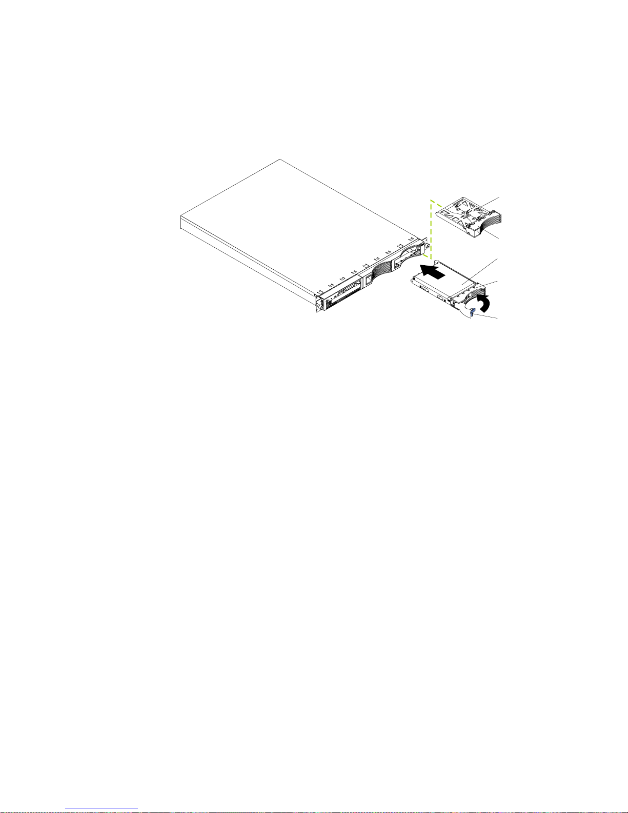
Chapter 5. Installing options 49
• Check the instructions that come with the drive for more information about
installing your drive.
Installing or replacing a hard disk drive
Refer to the following illustration to install a hard disk drive.
Note: The illustrations in this document might differ slightly from your hardware.
Attention: When you handle static-sensitive devices, take precautions to avoid
damage from static electricity. For details on handling these devices, refer to
“Handling static-sensitive devices” on page 38.
Complete the following steps to install or replace a hard disk drive:
1. Review the information in “Safety information” on page 39.
2. If you are installing a non-hot-swap disk drive, turn off the server and all attached
devices.
3. Remove the filler panel or defective hard drive from one of the hard disk drive
bays.
4. Install the new hard disk drive in the drive bay:
a. Ensure that the tray handle is open (that is, perpendicular to the drive).
b. Align the rails on the drive assembly with the guide rails in the drive bay.
c. Gently push the drive assembly into the bay until the drive connects to the
backplane.
d. Push the tray handle toward the closed position until it locks the drive in
place.
5. If you are installing a non-hot-swap disk drive, connect the external cables and
power cords; then, turn on the server.
6. Check the hard disk drive status indicators to verify that the hard disk drives are
operating properly. (See “Major components of the IBM xSeries 135 appliance
server” on page 34 for the location of the status indicators.)
• If the amber light is on continuously, the drive has failed.
• If the green light flashes slowly (one flash per se cond), the drive is being
rebuilt.
• If the green light flashes rapidly (three flashes per second), the controller is
identifying the drive.
Slim filler
Filler panel
Hard disk drive
Drive tray
Drive tray handle
(in open position)
Page 62

50 IBM xSeries 135: User’s Referenc e
Memory
Adding memory to your server is an easy way to improve system performance. You
can increase the amount of memory in yo ur server by installing options called
memory-module kits. Each k it contains one industry-standard, dual-in-line memory
module (DIMM). Your server uses a noninterleaved memory configuration, which
enables you to add, remove, or replace one DIMM at a time. In an interleaved system
you would have to add, remove, or replace memory in sets.
Your server comes with a dual in-line memory module (DIMM) installed on the
system board in DIMM connector 1.
Complete the following steps to install a DIM M:
Attention: When you handle static-sensitive devices, take precautions to avoid
damage from static electricity. For details on handling these devices, refer to
“Handling static-sensitive devices” on page 38.
1. Review the information in “Safety information” on page 39.
2. Turn off the server and peripheral devices.
3. Remove all external cables from the server; then, remove the server from the rack
and remove the cover. For more information see “Removing the cover” on page
44 for instructions.
4. If necessary, remove the PCI card in slot 2 for easier access to the DIMM
connectors.
5. Touch the sta tic- protective bag contai ning the DIMM to any unpainted metal
surface on the server. Then, remove the DIMM from the package.
Attention: To avoid breaking the retaining clips or damaging the DIMM
connectors, handle the clips gently.
Page 63

Chapter 5. Installing options 51
6. Install the DIMM in the connector.
Attention: To prevent damage to the DIMM connectors, do not force the memory
module into the connector.
a. Turn the D I MM so that the index slots align correctly with the connector.
Note: The DIMM has two index slots, one in the center and the other on the
left half of the DIMM connector edge.
b. Insert the DIMM into the connector by pressing on both corners of the DIMM
at the same time. Be sure to press straight into the connector.
c. When installing a memory module, be sure that no gap exists between the
DIMM and the retaining clips. If a gap does exist between the memory
module and the retaining clips, remove the DIMM; then, reinsert the DIMM
properly.
Note: If you have oth e r op ti ons to install, install them now.
7. Replace the cover on the server; then, reinstall the server in the rack and connect
all external cables. For more information, see “Installing the cover” on page 56 for
instructions.
8. Turn on the server.
Note: When you restart the server, the system displays a message indicating
that the memory configuration has changed.
• If you just replaced a failed DIMM, you must start the
Configuration/Setup Utility program, select Advanced Setup,
select Memory Settings, highlight the connector or bank of
connectors that you want to enable, and then select Enable.
• In some memory configurations, the 3-3-3 beep code might sound
during POST, followed by a blank display screen. If this occurs and
the Boot Fail Count feature in the Start Options of the
Configuration/Setup Utility is set to Enabled (its default setting),
you must restart the server three times to force the system BIOS to
reset the memory connector or bank of connectors from Disabled to
Enabled.
Connector 1
Connector 2
Connector 3
Connector 4
Page 64

52 IBM xSeries 135: User’s Referenc e
Microprocessor
Your server comes with one microprocessor installed on the system board.
Notes:
1. Before you install a microprocessor, review the documentation that comes with
the microprocessor, so that you can determine whether you need to update the
server basic input/output system (BIOS). The latest level of BIOS for your server
is available through the World Wide Web. Refer to “Getting help, service, and
information” on page 100 for the appropriate World Wide Web addresses.
2. The microprocessor is installed in microprocessor connector 1, which is the
microprocessor connector closer to the DIMM connectors.
Note: If you need to replace an existing microprocessor, call for service.
Complete the following steps to install a microprocessor:
Attention: When you handle static-sensitive devices, take precautions to avoid
damage from static electricity. For details on handling these devices, refer
to“Handling static-sensitive devices” on page 38.
1. Review the information in “Safety information” on page 39.
2. Turn off the server and peripheral devices.
3. Remove all external cables from the server; then, remove the server from the rack
and remove the cover. For more information see “Removing the cover” on page
44 for instructions.
4. Remove the clear shield from the server and store it in a safe place.
5. Lift up the microprocessor release lever and remove the terminator card from the
microprocessor connector. (After you remove the new microprocessor from the
static-protective bag, place the terminator card in the bag and store it in a safe
place. If you ever remove the microprocessor and do not replace the
microprocessor, you will need to install the terminator card again.).
Rear of server
Microprocessor
connector
Terminator
card
Microprocessor
release lever
Page 65

Chapter 5. Installing options 53
6. Install the microprocessor:
a. Touch the static-protective bag containing the new microprocessor to any
unpainted metal surface on the server; then, remove the microprocessor from
the package.
b. Orient the microprocessor over the microprocessor connector as shown in the
following illustration. Carefully press the microprocessor into the connector.
Attention: To avoid bending the pins on the microprocessor, do not use excessive
force when pressing it into the connector.
7. Push the microprocessor release lever down to lock the microprocessor in place.
Rear of server
Microprocessor
Microprocessor
connector
Microprocessor
orientation indicator
Microprocessor
release lever
Page 66

54 IBM xSeries 135: User’s Referenc e
8. Install the heat sink on the microprocessor:
a. Peel the plastic protective strip off the bottom of the heat sink. Make sure
that the square of thermal material is still on the bottom of the heat sink.
b. Align and place the heat sink on top of the microprocessor.
Note: Locate the slot in the channel of the heat sink. Orient the heat sink so
that the slot will be at the rear of the server.
c. Align and place the clip over the heat sink; then, snap the clip into place over
the heat sink with the heat-sink release lever in the up position.
Note: If you remove the microprocessor later, remember to install the
terminator card in the appropriate microprocessor connector.
d. Press the heat sink release lever down into the locked position when the clip
is in place.
9. Replace the clear shield.
Note: If you need to replace an existing microprocessor, call for service.
10. Replace the cover on the server; then, reinstall the server in the rack and connect
all external cables. For more information, see “Installing the cover” on page 56 for
instructions.
11. Start the server and run the Configuration/Setup Utility program.
Clip
Heat sink
Microprocessor
Terminator card
Heat sink release
lever
Slot
Top view of
heat sink
Page 67

Chapter 5. Installing options 55
Fan assembly replacement
Your server come s with six replaceable fans.
Attention: Replace a fan that has failed within 48 hours to help ensure proper
cooling.
The following illustration shows the replacement of a fan.
Complete the following steps to replace the fan assembly:
1. Review the information in “Safety information” on page 39.
2. Turn off the server and peripheral devices.
3. Remove all external cables from the server; then, remove the server from the rack
and remove the cover. For more information, see “Removing the cover” on page
44 for instructions.
4. Determine which fan to replace by checking the LED at each fan; a lit LED
indicates the fan to replace.
5. Remove the fan from the server:
a. Disconnect the fan cable from the system board.
b. Lift the fan away from the server.
6. Orient the fan so that the airflow arrow on the side of the fan is facing or pointing
toward the rear of the server.
Note: Proper airflow is from the front to the rear of the server.
7. Push the replacement fan assembly into the server until it clicks into place.
8. Connect the fan cable to the system board.
9. Replace the cover on the server; then, reinstall the server in the rack and connect
all external cables. For more information, see “Installing the cover” on page 56 for
instructions.
10. Start up the system. The system error light will either remain on or turn off. If the
system error light remains on, you will have to turn off the server to perform
further troubleshooting.
Air flow
Page 68

56 IBM xSeries 135: User’s Referenc e
Installing the cover
The following information describes the cover installation procedure.
Complete the following to install the server cover:
1. Clear any cables that might impede the replacement of the clear shield or the
cover.
2. Install the clear shield, if it was removed.
3. Install the cover by placing it into position and sliding it forward. Make sure that
the cover engages the tabs at the front and rear of the server.
4. Install the screws and secure the cover as shown.
5. Reinstall the server in the rack.
6. Reconnect the power cord and all external cables to the server, then plug the
power cords into electrical outlets.
Screws
Before sliding the cover forward, make sure that all of the tabs on the cover
will engage the ledge at the front of the server properly. If all the tabs do not
engage the ledge properly, it will be extremely difficult to remove the cover
later.
Important
Page 69

Chapter 5. Installing options 57
I/O connector locations and ports
The following illustration shows the input/output connectors (ports) that are
supported and the expansion slots on the rear of the server.
This section provides information about the input/output (I/O) ports on your server .
These ports include the following:
• Serial port
• Universal Serial Bus (USB) ports
• Console ports
• Ethernet ports
Serial port
Your server has one standard serial port. Some application programs require specific
ports, and some modems function properly only at certain communication port
addresses. Y ou might need to use the Configuration/Setup Utility program to change
communication port address assignments to prevent or resolve address conflicts. This
serial port is also manually configurable from inside the server. The following table
lists the function of each of the connectors that can be used to manually configure the
serial port. You will also need to refer to the figure in “System board options
connectors” on page 35.
Table 4. Serial port connectors on the system board
Connectors Port Description
J52 Serial port A Default connection. Used by the operating system. Modem
can be connected so that the system can dial out during
problems.
J51 Serial port B Used by the operating system only.
Ethernet 1
Ethernet 2
PCI slot 1
PCI slot 2
USB 1
USB 2
Console In
port
Console Out
port
Serial port
Page 70

58 IBM xSeries 135: User’s Referenc e
Viewing or changing the serial-port assignments
To view or change the serial-port assignments:
1. Restart the server and watch the monitor screen.
2. When the message Press F1 for Configuration/Setup appears, press F1.
3. From the main menu, select Devices and I/O Ports; then, press Enter.
Note: The Devices and I/O Ports choice appears only on the full configuration
menu. If you set two levels of passwords, you must type the
administrator password to access the full configuration menu.
4. Select the serial port; then, use the arrow keys to advance throug h the available
settings.
5. Select Save Setting s; then, s elect Exit Setup to exit from the Configuration/Setup
Utility main menu.
Serial-port connector
The following table shows the pin-n umber assignments for the 9-pin, male D-shell
serial-port connector on the rear of your server. These pin-number assignments
conform to the industry standard.
Universal Serial Bus ports
Your server has two Universal Serial Bus (USB) ports, which are configured
automatically. USB is a serial interface standard for telephony and multimedia
devices. It uses Plug and Play technology to determine the type of device that is
attached to the connector.
USB cables and hubs
You need a 4-pin cable to connect devices to USB 1 or USB 2. If you plan to attach
more than two USB devices, you must use a hub to connect the devices. The hub
provides multiple connectors for attaching additional external USB devices.
USB technology provides up to 12 megabits-per-second (Mbps) speed with a
maximum of 127 external devices and a maximum signal distance of five meters (16
ft.) per segment.
Table 5. Serial-port connectors pin-number assignments
Pin Signal Pin Signal
1 Data carrier detect 6 Data set ready
2 Receive data 7 Request to send
3Transmit data 8Clear to send
4 Data terminal ready 9 Ring indicator
5Signal ground
1
5
69
Page 71

Chapter 5. Installing options 59
USB-port connectors
Each USB port has an external connector on the rear of the server for attaching USB
compatible devices.
The following table shows the pin-number assignments for the USB-port connectors
on the rear of your server.
Console ports
There are two console ports on the rear of your server labeled In and Out. These ports
are used to create a console communications chain between servers and a console
(monitor, mouse, and keyboard). The xSeries 135 server does not support console
communications chains.
Connect a C2T device breakout cable to the Console out connector of the server; then,
connect your monitor, keyboard, and pointing device to the device breakout cable.
C2T device breakout cable
A keyboard, monitor, and mouse or pointing device are connected to your server
through the C2T device breakout cable. The keyboard and mouse cables have icons of
a keyboard and a mouse on their respective cable connectors for easy identification.
Keyboard connector
There is one keyboard connector on the end of the C2T device breakout cable. This
connector is identified by the keyboard icon.
Note: If you attach a standard (non-USB) keyboard to the keyboard connector, the
USB ports and devices will be disabled during the power-on self-test (POST).
Table 6. USB-port connector pin-number assignments
Pin Signal
1VCC
2-Data
3+Data
4Ground
Page 72

60 IBM xSeries 135: User’s Referenc e
The following table shows the pin-number a ssignments for the keyboard connector
on the end of the cable.
Video connector
The following table shows the pin-number assignments for the 15-pin analog video
connector on the end of the C2T device breakout cable. This cable is not labeled but is
easily identified by the dark blue 15-pin connector.
Auxiliary-device (pointing device) connector
On the end of the C2T device breakout cable, there is one auxiliary-device connector
that supports a mouse or other pointing device. This connector is identified by the
mouse icon.
Table 7. Keyboard-connector (6-pin female) number assignments
Pin I/O Signal
1I/O Data
2N/AReserved
3N/AGround
4 N/A +5 V dc
5 I/O Keyboard clock
6N/AReserved
Table 8. Video-connector (15-pin female) number assignments
Pin Signal Pin Signal Pin Signal
1 Red 6 Ground 11 Not connected
2 Green or monochrome 7 Ground 12 DDC SDA
3 Blue 8 Ground 13 Horizontal synchronization
(Hsync)
4Not connected 9+5 V dc
DDC
14 Vertical synchronization (Vsync)
5 Ground 10 Ground 15 DDC SCL
6
4
2
1
3
5
1
5
1115
Page 73

Chapter 5. Installing options 61
The following table shows the pin-number assignments for the auxiliary-device
connector on the end of the cable.
Ethernet ports
Your server comes with two integrated Ethernet controllers. These controllers pr ovide
an interface for connecting to 10-Mbps or 100-Mbps networks and provide full-duplex
(FDX) capability, whic h enables simultaneous transmission and reception of data on
the Ethernet local area network (LAN).
To access the Ethernet ports, connect a Category 3, 4, or 5 unshielded twisted-pair
(UTP) cable to the RJ-45 connector on the rear of your server.
Note: The 100BASE-TX Fast Ethernet standard requires that the cabling in the
network be Category 5 or higher.
Configuring the Ethernet controllers
When you connect your server to the network, the Ethernet cont rollers automatically
detect the data-transfer rate (10Mbps or 100Mbps) on the network and then set the
controllers to operate at the appropriate rate. In additio n, if the Ethernet ports that
your server is connected to support auto-negotiation, the Ethernet controllers will set
the appropriate duplex state. That is, the Ethernet controllers will adjust to the
network data rate, whether the data rate is standard Ethernet (10BASE-T), Fast
Ethernet (100BASE-TX), hal f duplex (HDX), or full duplex (FDX). The controllers
support half-duplex (HDX) and full-duplex (FDX) modes at both speeds.
The Ethernet controllers are PCI Plug and Play devices. You do not need to set any
jumpers or configure the controllers for your operating system before you use the
Ethernet controllers. However, you must install a device driver to enable your
operating system to address the Ethernet controllers.
Failover for redundant Ethernet
The IBM Netfinity 10/100 Ethernet Adapter or the IBM 10/100 EtherJet™ PCI family
of adapters are optional redundant network interface cards (NIC adapter) that you
can install in your server. If you install this NIC adapter and connect it to the same
logical segment as the primary Ethernet controller, you can configure the server to
support a failover function. You can configure either one of the integrated Ethernet
controllers or the NIC adapter as the primary Ethernet controller. In failover mode, if
Table 9. Auxiliary or pointing-device connector (6 pin female) number assignments
Pin Signal
1Data
2Not connected
3Ground
4+5 V dc
5Clock
6Not connected
6
4
2
1
3
5
Page 74

62 IBM xSeries 135: User’s Referenc e
the primary Ethernet controller detects a link failure, all Ethernet traffic associated
with it is switched to the redundant (secondary) con troller. This switching occurs
without any user intervention. When the primary link is restored to an operational
state, the Ethernet traffic switches back to the primary Ethernet controller.
High-performance Ethernet modes
Your Ethernet controllers support optional modes, such as teaming, priority packets,
and virtual LANs, which provide higher performance and throughput for your
server.
Teaming mode: Your Ethernet controllers provide options, called teaming options.
These options increase throughput and fault tolerance when running with Windows
NT
®
4.0 or NetWare 4.1x or later.
• Adapter fault tolerance (AFT) provides automatic redundancy for your adapter.
If the primary adapter fails, the secondary adapter takes over. Adapter fault
tolerance supports from two to four adapters per team.
• Adaptive load balancing (ALB) enables you to balance the transmission data
flow among two to four adapters. ALB also includes the AFT option. You can use
ALB with any 100BASE-TX switch.
• Cisco Fast EtherChannel (FEC) creates a team of 2 to 4 adapters to increase
transmission and reception thoughput. FEC a lso includes the AFT option. You
can use FEC only with a switch that has FEC capability.
Teaming requires you to install both integrated Ethernet controllers. For additional
information about the teaming opti ons, refer to the documentation that comes with
these additional adapters.
Priority Packet mode: Priority Packet is a traffic-prioritization utility that enables
you to set up filters to process high-priority traffic befor e normal traffic. You can send
information from critical nodes or applications with an indicated priority. Because
you set this priority at the host or entry point of the network, the network devices can
base forwarding decisions on priority information defined in the packet.
Priority Packet information is available on the IBM Networking site at
http://www.ibm.com/networking/support on the World Wide Web.
Priority Packet prioritizes traffic based on priority filters. These are parameters that
you assign to outgoing (transmit) packets. Using the priority filter wizard, you can set
up predefined or custom priority filters based on a node (MAC) address, Ethernet
type, or by various properties of the protocol and port. Priority Packet provides two
different methods for prioritizing traffic: IEEE 80 2.1p tagging and High Priority
Queue.
IEEE 802.1p is an IEEE standard for tagging, or adding additional bytes of
information to packets with different priority levels. Packets are tagged with 4
additional bytes, which increase the packet size and indicate a priority level. When
you send these packets out on the network, the higher priority packets are transferr ed
first. Priority-packet tagging (also known as Traffic Class Expediting) enables the
adapter to work with other elements of the network (such as switches and routers) to
deliver priority packets first. You can assign specific priority levels from 0 (low) to 7
(high).
You can assign values to packets based on their priorities when you use the IEEE
802.1p standard for packet tagging . This method requires a network infrastructure
that supports packet tagging. The routing devices receiving and transferring these
packets on your network must support 802.1p for tagging to be effective.
Page 75

Chapter 5. Installing options 63
After you set up the priority filter in Priority Packet, start IBMSet and click
802.1p/802.1Q Tagging on the Advanced tab.
Note: IEEE 802.1p tagging increases the size of the packets that it tags. Some hubs
and switches will not recognize the larger packets and will drop them. Check
your hub or switch documentation to see if they support 802.1p. (You can
configure the switch to strip the tags from the packets and send it on to the
next destination as normal traffic.) If these devices do not support 802.1p or if
you are not sure, use High Priority Queue (HPQ) to prioritize network traffic.
The requirements for effectively using IEEE 802.1p tagging are:
• The other devices receiving and routing 802.1p tagged packets must support
802.1p.
• The adapters on these devices must support 802.1p. The Ethernet controller in
your server, a ll IB M Netfinity 10/100 Ethernet Security Adapters, and IBM
10/100 Ethernet Server Adapters support 802.1p.
• The adapter cannot be assigned to an adapter team.
• If you are setting up virtual local area networks (VLANs) and packet tagging on
the same adapter, 802.1p/802.1Q tagging must be enabled on the IBMSet
Advanced tab.
If your network infrastructure devices do not support IEEE 802.1p or you ar e not sur e,
you can still define filters and send packets as high priority. While High Priority
Queue (HPQ) does not provide the precise priority levels of 802.1p tagging, it does
assign traffic as either high or low priority and sends high-priority packets first.
Therefore, if there are multiple applications on a system sending packets, the packets
from the application with a filter are sent out first. HPQ does not change network
routing, nor does it add any information to the packets.
To assign HPQ, you can specify it using Priority Packet when you create or assign a
filter.
To effectively use HPQ, the adapter cann ot be assigned to an adapter team.
Virtual LAN mode: A VLAN is a logical grouping of network devices that are put
together as a LAN, regardless of their physical grouping or collision domains. Using
VLANs increases network performance and improves network security.
VLANs offer you the ability to group users and devices together into logical
workgroups. This can simplify network administration when connecting clients to
servers that are geographically dispersed in a building, campus, or enterprise
network.
Typically, VLANs are configured at the switch and any computer can be a member of
one VLAN per installed network adapter . Your Ethernet controller supersedes this by
communicating directly with the switch, enablin g multiple VLANs on a single
network adapter (up to 64 VLANs).
To set up VLAN membership, your Ethernet controller must be attached to a switch
that has VLAN capability.
To join a VLAN from TurboLinux 6.05:
1. Create a VLAN on the switch. Use the parameters you assign there to join the
VLAN from the server. Refer to your switch documentation for more information.
2. Double-click the Network icon in the Control Panel windo w.
3. On the Adapters tab, select the adapter that you want to be on the VLAN, and
click Properties.
Page 76

64 IBM xSeries 135: User’s Referenc e
4. In IBMSet, click Join VLAN. Note that VLANs cannot be assigned to adapters
that are already defined to have an adapter teaming option.
5. Type the VLAN ID and VLAN name. The VLAN ID must match the VLAN ID of
the switch. The ID range is from 1 to 1000. The VLAN name is for information
only and does not need to match the name on the switch.
6. Click Join VLAN. Repeat steps 3 through 5 for each VLAN that you want the
server to join. The VLANs that you add are listed on the Adapters tab.
7. Click Close, and restart the computer.
Ethernet port connector
The following table shows the pin-number assignments for the RJ-45 connector. These
assignments apply to both 10BASE-T and 100BASE-TX devices.
Working with cables
The following sections discuss how to cable your appliance server to an existing
network. For an illustration of the rear connectors of the a ppliance server, see “I/O
connector locations and ports” on page 57.
Connecting the IBM xSeries 135 appliance server to the
network
The IBM xSeries appliance server has two Ethernet connectors that you can use to
integrate the appliance server to an existing local area network (LAN). You can use
one or both Ethernet ports, but some software features can function pro perly only if
the server is connected to the LAN through Ethernet port 1.
Connect Category 5 Ethernet cable to the server Ethernet ports to install the server in
an existing network.
Cable management
Use the cable ties and hook-and-loop straps that are supplied with your server to
secure the cables.
Attention: Do not secure cables too tightly. Overtightening can cause internal damage
to cables
Table 10. Eth ernet RJ- 45 conne ct or pin-num ber assign men ts .
Pin Signal Pin Signal
1 Transmit data+ 5 Not connected
2 Transmit data- 6 Receive data 3 Receive data+ 7 Not connec ted
4 Not connected 8 Not connected
Page 77

© Copyright IBM Corp. 2000 65
Chapter 6. Solving Problems
This section provides basic troubleshooting information to help you resolve some
common problems that might occur with your server.
If you cannot locate and correct the problem using the information in this section,
refer to “Getting help, service, and information” on page 100 for more information.
Diagnostic tools overview
The following tools are available to help you identify and resolve hard ware-related
problems:
• POST beep codes, error messages, and error logs
The power-on self-test (POST) generates beep codes and messages to indicate
successful t es t c o mpletion or the detection of a p roblem. See “POST” on page 67
for more information.
• Diagnostic programs and error messages
The server diagnostic programs are stored in upgradable read-only memory
(ROM) on the system board. These programs are the primary method of testing
the major components of your server. See “Diagnost ic programs and error
messages” on page 79 for more information.
• Troubleshooting ch arts
These charts list problem symptoms, along with suggested steps to correct the
problems. See the “Troubleshooting charts” on page 89 for more information.
• Customized support page
You can create a customized support page that is specific to your hardware,
complete with Frequently Asked Questions, parts information, technical hints
and tips, and downloadable files. In additi on, you can choose to receive
electronic mail (e-mail) notifications whenever new information becomes
available about your registered products.
After you register and create a profile for your xSeries products, you can
diagnose problems using the IBM Online As sistant and you can participate in
the IBM discussion forum. For more detailed information about re gistering and
creating a customized profile for your IBM produ cts, visi t the following
addresses on the Web:
— http://www.ibm.com/pc/register
— http://www.ibm.com/pc/support
Page 78

66 IBM xSeries 135: User’s Referenc e
S
erver Support
After you register and profile, you will be able to:
• Diagnose problems using the IBM Online Assistant
• Participate in the IBM discussion forum
• Receive e-mail notifications of technical updates
related to your profiled products
Register at:
Profile at:
http://www.ibm.com/pc/register
http://www.ibm.com/pc/support
Register and profile your server
Yes
No
No
Phone an
IBM HelpCenter
Use the troubleshooting
information provided with
your server to determine
the cause of the problem
and the action to take.
You can check the hints and
tips web site at:
http://www.ibm.com/pc/support
No
No
Yes
Yes
Yes
Check all cables for loose connections
and verify that all optional devices you
installed are on the ServerProven list.
You can view the ServerProven list at:
http://www.ibm.com/pc/compat
Server working
properly?
Problem
solved?
Problem
solved?
Problem
solved?
You can view a list of
IBM HelpCenter phone numbers at:
http://www.ibm.com/pc/support
Page 79

Chapte r 6. Solving Problems 67
POST
When you turn on the server, it perfor ms a series of tests to check the operation of
server components and some of the options that are installed in the server. This series
of tests is called the power-on self-test or POST.
If POST finishes without detecting any problems, a single beep sounds and the first
screen of your operating system or application program appears.
If POST detects a problem, more than one beep sounds and an error message appears
on your screen. See “POST beep code descriptions” and “POST error messages” on
page 70 for more information.
Notes:
1. If you have a power-on password set, you must type the password and press
Enter, when prompted, before POST will continue.
2. A single problem might cause several error messages. When this occurs, work to
correct the cause of the first error message. After you correct the cause of the first
error message, the other error messages usually will not occur the next time you
run the test.
POST beep code descriptions
Beep codes are sounded in a series of long and short beeps.
The possible types of beep codes that your server might emit include the following:
No beeps If no beep occurs after your server completes POST, call for service.
Continuous beep
Your startup (boot) microprocessor has failed, or your system board or
speaker subsystem might contain a failing component. If the system
continues through POST with no errors, call for service. If no video appears,
the startup processor has failed; replace the startup processor.
One short beep
One beep indicates that your server successfully completed POST. POST
detected no configuration or functional errors. One beep also occurs after
your server completes POST if you enter an incorrect power-on password.
Two short beeps
POST encountered an error. The Co nfiguration/Setup Utility program will
display additional information; follow the instructions that appear on the
screen. See “POST error messages” on page 70 for descriptions of the text
messages that might appear.
Three short beep s
A system memory error has occurred. This combination occurs only if the
video Basic Input/Output System (BIOS) cannot display the error message.
Replace the failing memory module.
Repeating short beeps
The system board might contain a failing component, your keyboard might
be defective, or a key on the keyboard might be stuck. Ensure that:
• Nothing is resting on the keyboard and pressing a key.
• No key is stuck.
• The keyboard cable is connected correctly to the keyboard and to the
correct connector on the server.
Page 80

68 IBM xSeries 135: User’s Referenc e
Running the diagnostic tests can isolate the server component that failed, but
you must have your system serviced. If the error message remains, call for
service.
Note: If you just connected a new mouse or other pointing device, turn off
the server and disconnect that device. Wait at least 5 seconds; then,
turn on the server. If the error message goes away, replace the device.
One long and one short beep
POST encountered an error on a video adapter. If you are using the integrated
video controller, call for service. If you are using an optional video adapter,
replace the failing video adapter.
One long and two short beeps
A video I/O adapter ROM is not readable, or the video subsystem is
defective. If you hear this beep combination twice, both the system board and
an optional video adapter have failed the test. This beep combination might
also indicate that the system board contains a failing component.
One long and three short beeps
The system-board video subsystem has not detected a monitor conn ection to
the server. Ensure that the monitor is connected to the server. If the problem
persists, replace the monitor.
Two long and two short beeps
POST does not support the optional video adapter. This beep combination
occurs when you install a video adapter that is incompatible with your server.
Replace the optional video adapter with one that the server supports, or use
the integrated video controller.
Page 81

Chapte r 6. Solving Problems 69
POST beep codes
In addition to the beep codes that are described in “POST beep code descriptions” on
page 67, your computer might emit beep codes that are described in the following
table. The numbers and hyphens below describe the sequence of beeps and pauses.
For example, a 1-2-3 beep code is one beep, a pause, two consecutive beeps, another
pause, and three more consecutive beeps.
Table 11. POST beep codes
Beep code Description Action
1-1-2 Microprocessor register test has failed. Call for service.
1-1-3 CMOS write/read test has failed.
1-1-4 BIOS ROM checksum has failed.
1-2-1 Programmable Interval Timer test has failed.
1-2-2 DMA initialization has failed.
1-2-3 DMA page register write/read test has failed.
1-4-3 Interrupt vector loading test has failed.
2-1-1 Secondary DMA register test has failed.
2-1-2 Primary DMA register test has failed.
2-1-3 Primary interrupt mask register test has failed.
2-1-4 Secondary interrupt mask register test has failed.
2-2-1 Interrupt vector loading has failed.
2-2-2 Keyboard controller test has failed.
2-2-3 CMOS power failure and checksum checks have failed.
2-2-4 CMOS configuration information validation has failed.
2-3-2 Screen memory test has failed.
2-3-3 Screen retrace tests have failed.
2-3-4 Search for video ROM has failed.
2-4-1 Screen test indicates the screen is operable.
3-1-1 Timer tick interrupt test h as failed.
3-1-2 Interval timer channel 2 test has failed.
3-1-3 RAM test has failed above address hex 0FFFF.
3-1-4 Time-of-Day clock test has failed.
3-2-1 Serial port test has failed.
3-2-2 Parallel port test has failed.
3-2-4 Compari son of CMOS memory size against act u al has
failed.
3-3-2 I2C bus has failed.
Page 82

70 IBM xSeries 135: User’s Referenc e
POST error messages
The following tables provide information about the POST error messages that can
appear during startup.
2-3-1 Screen initialization has failed. Turn off the
server and then
restart the
server. If the
problem
persists, call for
service.
1-2-4 RAM refresh verification has failed. Reseat the
memory
modules or
install a memory
module. If the
problem
persists, call for
service.
1-3-1 First 64 Kb RAM test has failed.
1-3-2 First 64 Kb RAM parity test has failed.
3-3-1 A memory size mismatch has occurred.
3-3-3 Attention: In some memory configurations, the 3-3-3 beep
code might sound during POS T followe d by a blan k display
screen. If this occurs and the Boot Fail Count feature in the
Start Options of the Configuration/Setup Utility is set to
Enabled (its default setting), you must restart the server
three times to force the system BIOS to reset the memory
connector or bank of connectors from Disabled to Enabled.
Table 12. POST erro r messa ges
POST message Description
062 The server failed to start on three consecutive attempts.
All caches are disabled. Repeatedly turning the server on and then off or resetting the server
might cause this problem.
Action: Start the Configuration/Setup Utility program and verify that all settings are
correct. See “Using the Configuration/Setup Utility program” on page 12 for more
information. Use the Cac he Control selection in the Advanced Setup menu of the
Configuration/Setup Utility program to enable the caches.
If the problem persists, call for service. When the problem is corrected, be sure to enable the
caches.
101 102 106 An error occurred during the system board and microprocessor test.
Action: Call for service.
114 An adapter read-only memory (ROM) error occurred.
Action: Remove the options. If you can start the server without the options installed,
reinstall each option one at a time and retest after each is reinstalled. When an
option fails, replace it.
If you cannot isolate and correct the pr ob lem, call for serv ic e.
129 An error was detected in the L1 cache of one of the microprocessors.
Action: 1. If you just i nstalled a micr opr ocesso r, verify that the micr opr oce ssor i s inst alled
and seated correctly.
2. If the problem persists, call for service.
Table 11. POST beep codes
Page 83

Chapte r 6. Solving Problems 71
151 A real-time clock (RTC) error occurred.
Action: Call for service.
161 The real-time clock battery has failed.
Action: Replace the battery you rself or call for s ervice.
You can use the server until you replace the battery. However, you must run the
Configuration/Setup Utility program and set the time and date and other custom settings each
time you turn on the server.
162 A change in device configuration occurred. This error occurs under one or more of the following
conditions:
• A new device has been installed.
• A device has been moved to a different location or cable connection.
• A device has been removed or disconnected from a cable.
• A device is failing and is no longer recognized by the server as being installed.
• An external device is not turned on.
• An invalid checksum is detected in the battery-backed memory.
Action: Verify that all external devices are turned on. You must turn on external devices
before turning on the server.
If you did not add, remove, or change the location of a device, a device is probably failing.
Running a diagnostic test might isolate the failing device.
If you cannot isolate and correct the pr ob lem, call for serv ic e.
163 The time of day has not been set.
Action: Set the correct date and time. If the date and time are set correctly and saved, but the
163 error message reappears, call for service.
Y ou can use the se rver until the syste m is serviced, but any applicati on progr ams that use the date
and time will be affected.
164 A change in the memory configuration occurred. This message might appear after you add or
remove memory.
Note: The server can be used with decreased memory capacity.
Action: 1. If POST error message 289 also occurred, follow the instructions for that error
message first.
2. If you just installed or removed memory, run the Configuration/Setup Utility
program (see “Using the Confi gura ti on/ Setu p U til ity pr o gra m ” on page 12 for
more information); then, exit, saving the new configuration settings.
If the message appears again, shut down the server, reseat the memory
modules, and restart the server.
If the problem persists, call for service.
175 A vital product data (VPD) error occurred.
Action: Call for service.
176 177 178 A security hardware error occurred.
Action: Check for indications that someone has t ampered with the server. If no one has
tampered with the server, call for service.
Table 12. POST erro r messa ges
POST message Description
Page 84

72 IBM xSeries 135: User’s Referenc e
184 The power-on password information stored in your server has been removed.
Action: From the Configuration/ Setup Utili ty pr ogram m ain menu, s elect Sy stem Security.
See “Using the Configuration/Setup Utility program” on page 12). Then, follow the
instructions on the screen.
If this information cannot be restored, call for service.
185 A power failure damaged the stored information about the drive-startup sequence.
Action: From the Configuration/Setup Utility program main menu, select Start Options;
then, follow the instructions on the screen. See “Using the Configuration/S etup
Utility program” on page 12.
If this information cannot be restored, call for service.
186 A syste m board or hardware error occurred.
Action: Call for service.
187 The VPD serial number is not set.
Action: The system serial number is set in the VPD EEPROM at th e time of manufacturing.
If the system board h as b een r eplaced, the system serial number will be invalid a nd
should be set. From the main menu of the Configuration/Setup Utility program,
select System Information, then select Product Data. “Using the
Configuration/Setup Utility program” on page 12. If the problem persists, call for
service.
188 A vital product data (VPD) error occurred.
Action: Call for service.
189 An attempt has been made to access the server with invalid passwords. After three incorrect
attempts, the server locks up; that is, the logon data fields are no longer available to the user.
201 An error occurred during the memory controller test. This error can be caused by:
• Incorrectly installed memory
• A failing memory module
• A system board problem
Action: 1. If you just installed memory, verify that the new memory is correct for your
server. Also verify that the memory is installed and seated correctly.
2. If the problem persists, call for service.
229 An error was detected in the L2 cache of one of the microprocessors.
Action: 1. If you just i nstalled a micr opr ocesso r, verify that the micr opr oce ssor i s inst alled
and seated correctly.
2. If the problem persists, call for service.
289 An error occurred during POST memory tests, and a failing DIMM was disabled.
Note: You can use the server with decreased memory.
Action: 1. If you just installed memory, verify that the new memory is correct for your
server. Also verify that the memory is installed and seated correctly. Start the
Configuration/Setup Utility program and select Memory Settings from the
Advanced Setup menu to enable the DIMM. See “Using the
Configuration/Setup Utility program” on page 12.
2. If the problem remains, replace the failing DIMM.
If the problem persists, call for service.
Table 12. POST erro r messa ges
POST message Description
Page 85

Chapte r 6. Solving Problems 73
301 303 An error occurred during the keyboard and keyboard controller test. These error messages also
might be accompanied by continuous beeping.
Action: Ensure that:
• Nothing is resting on the keyboard and pressing a key.
• No key is stuck.
• The keyboard cable is connected correctly to the keyboard and to the correct
connector on the server.
Running the diagnostic tests can isolate the server component tha t failed, but you must have your
system serviced. If the error message remains, call for service.
Note: If you just connected a new mouse or other pointing device, turn off the serv er and
disconnect that device. Wait at least 5 seconds; then, turn on the server. If the error
message goes away, replace the dev ic e.
602 Invalid diskette boot record
Action: 1. Replace the dis kette.
2. If the problem persists, make sure that the diskette drive cables are correctly
and securely connected.
3. If the problem remains, replace the diskette drive.
If the problem persists, call for service.
604 An error occurred during a diskette drive test.
Action: 1. Verify that the Configuration/Setup Utility program correctly reflects the type
of diskette drive that you have installed. See “Using the Configuration/Setup
Utility program” on page 12.
2. Run the diagnostic tests. If the diagnostic tests fail, call for service.
662 A diskette drive configuration error occurred.
Action: If you removed a diskette drive, make sure that the diskette drive setting is correct
in the Configuration/Setup Utility program. See “Using the Configuration/Setup
Utility program” on page 12. If the setting is not correct, change it.
If the problem persists, call for service.
962 A parall el port configuratio n error occurred.
Action: If you changed a hardware option, make sure that th e pa ra llel port setting is correct
in the Configuration/Setup Utility program. See “Using the Configuration/Setup
Utility program” on page 12. If the setting is not correct, change it.
If the problem persists, call for service.
Table 12. POST erro r messa ges
POST message Description
Page 86

74 IBM xSeries 135: User’s Referenc e
11xx An error occurred during the system-board serial port test.
Action: If you have a modem, serial printer, or other serial device attached to your server,
verify that the serial cable is connected correctly. If it is, use the following
procedure:
1. Turn off the server.
2. Disconnect the serial cable from the serial port.
3. Wait five seconds; then, turn on the server.
If the POST error message does not reappear, either the serial cable or the device is probably
failing. See the documentation that comes with the serial device for additional testing
information.
If the POST error message reappears, call for service.
1162 The serial port configuration conflicts with another device in the system.
Action: 1. Make sure the IRQ and I /O port assignments needed by the serial port are
available.
2. If all interrupts are being used by adapters, you might need to remove an
adapter to make an i nterr upt ava ilable to the s erial port , or for ce ot he r ada pters
to share an interrupt.
1800 A PCI adapter has requested a hardware interrupt that is not available.
Action: 1. Make sure that the PCI adapter and all other adapters are set correctly in the
Configuration/Setup Utility program. If the interrupt resource settings are not
correct, change the settings.
2. If all interrupts are being used by other adapters, you might need to remove an
adapter to make an interrupt available to the PCI adapter, or force other
adapters to share an interrupt.
1962 No valid startup devices were found. The system cannot find the startup drive or operating
system.
Action: Be sure that the drive that you want to start from is in the startup sequence.
1. Select Start Options from the Configuration/Setup Utility program main
menu. See “Using the Configuration/ Setup Utilit y progra m” on page 12. If you
are unable to set the star tu p seq ue nc e, call for se rv ic e.
2. Check the list of startup devices in the Startup device data fields. Is the drive
you want to start from in the startup sequence?
Yes Exit from this screen; then, select Exit Setup to exit the
Configuration/Setup menu. Go to step 3..
No Follow the instructions on the screen to add the drive; then, save the
changes and exit from the Configuration/Setup menu. Restart the
server.
3. Is an operating system installed?
Yes Turn off the server. Go to step 4..
No Install the operating system in your server; then, follow your
operating system instructions to shut down and restart the server.
4. During server star tup, watch for messages indicating a hardware problem.
If the same error message appears, call for service.
Table 12. POST erro r messa ges
POST message Description
Page 87

Chapte r 6. Solving Problems 75
2400 An error occurred duri ng the testing of the video contr oller on the sys tem board. Th is error can be
caused by a failing monitor, a failing system board, or a failing video adapter (if one is installed).
Action: Verify that the monitor is connected correctly to the video connector. If the monitor
is connected correctly, call for service.
2462 A video memory configuration error occurred.
Action: Make sure that the monitor cables a r e corr ectly and s ecur ely conn ected to the server.
If the problem persists, call for service.
5962 An IDE CD-ROM configuration error occurred.
Action: Check the signal and power cable connections to the CD-ROM drive.
If the problem persists, call for service.
8603 An error occurred during the mouse (pointing device) controller test. The addition or removal of
a mouse, or a failing system board can cause this error.
Note: This error also can occur if electrical power was lost for a very brief period and then
restored. In this case, turn off the server for at least 5 seconds; then, turn it back on.
Action: Ensure that the keyboard and mouse (pointing device) are attached to the correct
connectors. If they are connec ted correctly, use the following procedure:
1. Turn off the server.
2. Disconnect the mouse from the server .
3. T urn on the server.
If the POST error message does not reappear, the mouse is probably failing. See the
documentation that comes with the mouse for additional testing information. If the problem
remains, replace the mouse or pointing device.
If the POST error message reappears, run the diagnostic tests to isolate the problem. If the
diagnostic tests do not find a problem and the POST error message remains, call for service.
00012000 Processor machine check.
Action: 1. Update the system BIOS.
2. If the problem persists, replace t he microprocessor.
00019501 Processor 1 is not functioning.
Action: Replace microprocessor 1.
If the problem persists, call for service.
00019701 Processor 1 failed the built-in self-test.
Action: Replace microprocessor 1.
If the problem persists, call for service.
00180100 A PCI adapter has requested memory resources that are not available
Action: 1. Make sure that the PCI adapter and all other adapters are set correctly in the
Configuration/Setup Utility program. See “Using the Configuration/Setup
Utility program” on page 12. If the memory resource settings are not correct,
change the settings.
2. If all memory resources are being used, you might need to remove an adapter
to make memory available to the PCI adapter. Disabling the adapter BIOS on
the adapter might correct the error. Refer to the documentation that is provided
with the adapter.
Table 12. POST erro r messa ges
POST message Description
Page 88

76 IBM xSeries 135: User’s Referenc e
00180200 A PCI adapter has requested an I/O address that is not available, or the PCI adapter might be
defective.
Action: 1. Make sure th at the I/O addre sses for th e PCI adap ter and all o ther adap ters ar e
set correctly in the Conf iguration/Setup Utility program. See “Using the
Configuration/Setup Utility program” on page 12.
2. If the I/O port resource settings a re correct, the PCI adapter migh t be defectiv e.
Call for service.
00180300 A PCI adapter has requested a memory address that is not available, or the PCI adapter might be
defective.
Action: 1. Make sure that the memory addresses for all other adapters are set correctly in
the Configuration/Setup Utilit y pr og ra m . If the memory r esource settings are
not correct, change the settings. “Using the Configuration/ Setup Utility
program” on page 12.
2. If the memory resource settings are corr ect, the PCI adapter might be d efective.
Call for service.
00180400 A PCI adapter has requested a memory address that is not available .
Action: If all memory addresses are being used, you might need to remove an adapter to
make memory addre ss spac e av ai lab l e to the PC I ada pter. Disabling the adapter
BIOS on the adapter might correct the error. Refer t o the documentation that is
provided with the ada p ter.
00180500 A PCI adapter ROM er ror occurred.
Action: Remove the PCI adapters. If you can start the server wi thout the adapters, reinstall
each adapter one at a time an d rete st after eac h is reinst alled. When an adapter f ails,
replace it.
If you cannot isolate and correct the pr ob lem, call for serv ic e.
00180600 A PCI-to-PCI bridge error occurred. More than one PCI bus tried to access memory below 1 MB.
Action: Remove the PCI adapter th at has the PCI bridge. If you can start the server without
the adapter, reinstall and retest the adapter. If the adapter fails, replace it.
If you cannot isolate and correct the pr ob lem, call for serv ic e.
00180700 xxxxyyyy System board PCI device does not respond or disabled by user. (Where xxxx is the PCI
vendor ID and yyyy is the PCI device ID).
Action: Start the Configuration/Setup Utility program, select Devices and I/O Ports, and
make sure that the device is enabled. See “Using the Configuration/Setup Utility
program” on page 12. If the problem persists, call for service.
00180800 An unsupported PCI d evice is installed.
Action: Remove the PCI adapters. If you can start the server wi thout the adapters, reinstall
each adapter one at a time an d rete st after eac h is reinst alled. When an adapter f ails,
replace it.
If the problem persists, call for service.
00181000 PCI error.
Action: Remove the PCI adapters. If you can start the server wi thout the adapters, reinstall
each adapter one at a time an d rete st after eac h is reinst alled. When an adapter f ails,
replace it.
If the problem persists, call for service.
Table 12. POST erro r messa ges
POST message Description
Page 89

Chapte r 6. Solving Problems 77
01295085 The ECC checking hardware test failed.
Action: Call for service.
01298001 No update data is available for processor 1.
Action: Update the system BIOS to a lev el t hat su pport s t he mic r oprocessor that is installed
in the server.
01298101 The update data for processor 1 is incorrect.
Action: Update the system BIOS to a lev el t hat su pport s t he mic r oprocessor that is installed
in the server.
I9990301 A hard disk drive error occurred.
Action: Call for service.
I9990305 POST could not find an operating system.
Action: Install an operating system. If you have already installed the operating system,
check the drive startup sequence. If the drive sequence is correct, run the di agnostic
tests to verify that the hard disk drive is functioning c orrectly. If there is a problem
with the hard disk drive (such as a bad sector), you might need to reinstall the
operating system.
If you cannot reinstall the operating system, call for service.
I9990650 AC power has been restored.
Action: No action is required. This message appears each time ac power is restored to the
server afte r an ac power loss.
Other Numbers POST found an error.
Action: Follow the instructions on the screen.
Table 12. POST erro r messa ges
POST message Description
Page 90

78 IBM xSeries 135: User’s Referenc e
Event/error logs
The POST error log contains the three most recent error codes and messages that the
system generated during POST. The System Event/Error log contains all messages
that were issued during POST.
To view the contents of the System Event/Error log, start the Configuration/Setup
Utility program; then, select Event/Error Logs from the main menu. See “Using the
Configuration/Setup Utility program” on page 12.
Small computer system interface (SCSI) messages
The following table lists actions to take if you receive a SCSI error message.
Note: If your server does not have a hard disk drive, ignore any message that
indicates that the BIOS is not installed.
You will get these messages only when running the SCSISelect Utility.
Table 13. SCSI mess ag es
SCSI messages Description
All One or more of the following might be causing the pr o blem.
• A failing SCSI device (adapter, drive, controller)
• An improper SCSI configuration
• Duplicate SCSI IDs in the same SCSI chain
• An improperly installed SCSI terminator
• A defective SCSI terminator
• An improperly installed cable
• A defective cable
Action:
Verify that:
• The external SCSI devices are turned on. External SCSI devices must
be turned on before the server.
• The cables for all external SCSI devices are connected correctly.
• The last device in each SCSI chain is terminat ed properly.
• The SCSI devices are configured correctly.
If you have verified these items and th e problem persists, run the
diagnostic programs to obtain additiona l information about the failing
device. If the erro r remains or recurs, call for servic e.
Page 91

Chapte r 6. Solving Problems 79
Diagnostic programs and error messages
The server diagnostic programs are stored in upgradable read-only memory (ROM)
on the system board. These programs are the primary method of testing the major
components of your server.
Diagnostic error messages indicate that a problem exists; they are not intended to be
used to identify a failing part. Troubleshooting and servicing of complex problems
that are indicated by error messages should be performed by trained service
personnel.
Sometimes the first error to occur causes additional erro rs. In this case, the server
displays more than one error message. Always follow the suggested action
instructions for the first error message that appears.
The following sections contain the error codes that might appea r in the detailed test
log and summary log when runnin g the diagnostic programs.
The error code format is as follows:
fff-ttt-iii-date-cc-text message
where:
fff is the three-digit function code that indicates the
function being tested when the error occurred. For
example, function code 089 is for the microprocessor.
ttt is the three-digit failure code that indicates the exact
test failure that was encountered. (These codes are
for trained service personnel and are described in the
Hardware Maintenance Manual.)
iii is the three-digit device ID. (These codes are for
trained service personnel and are described in the
Hardware Maintenance Manual.)
date is the date that the diagnostic test was run and the
error recorded.
cc is the check value that is used to verify the validity of
the information.
text message is the diagnostic message that indicates the reason
for the problem.
Page 92

80 IBM xSeries 135: User’s Referenc e
Text messages
The diagnostic text message format is as follows:
Function Name: Result (test specific string)
where:
Function Name
is the name of the function being tested when the error occurred. This
corresponds to the function code (fff) given in the previous list.
Result can be one of the following:
Passed This result occurs when the diagnostic test
completes without any errors.
Failed This result occurs when the diagnostic test
discovers an error.
User Aborted This result occurs when you stop the
diagnostic test before it is complete.
Not Applicable This result occurs when you specify a
diagnostic test for a device that is not
present.
Aborted This result occurs when the test could not
proceed because of the system configuration.
Warning This result occurs when a possible problem
is reported during the diagnostic test, such
as when a device that is to be tested is not
installed.
Test Specific String This is additional information that you can
use to analyz e the problem.
Starting the diagnostic programs
You can press F1 while running th e di agnostic programs to obtain Help information.
You also can press F1 from within a Help screen to obtain online documentation from
which you can select different categories. To exit from Help, press Esc.
To start the diagnostic programs:
1. Turn on the server and watch the screen.
2. When the message F2 for Diagnostics appe ars, press F2.
3. Type the appropriate password; then, press Enter.
4. Select either Extended or Basic from the top of the screen.
5. When the Diagnostic Programs screen appears, select the test you want to run
from the list that appears; then, follow the instructions on the screen.
Page 93

Chapte r 6. Solving Problems 81
Notes:
a. If the server stops during testing and you cannot continue, restart the server
and try running the diagnostic programs again. If the problem persists, call
for service.
b. The keyboard and mouse (pointing device) tests assume that a keyboard and
mouse are attached to the server.
c. If you run the diagnostic programs with no mouse attached to your server,
you will not be able to navigate between test categories using the Next Cat
and Prev Cat buttons. All other function s provided by mo use-selectable
buttons are also available using the function keys.
d. You can test the U SB keyboard by using the regular keyboard test. The
regular mouse test can test a USB mouse. Also, you can run the USB hub test
only if there are no USB devices attached.
e. Y ou can view server configuration information (such as system configuration,
memory contents, interrupt request (IRQ) use, direct memory access (DMA)
use, device drivers, and so on) by selecting Hardware Info from the top of the
screen.
When the tests have completed, you can view the test log by selecting Utility from the
top of the screen.
If the diagnostic programs do not detect any hardware error but the problem persists
during typical server operations, a software error might be the cause. If you suspect a
software problem, refer to the information that comes with the software package.
Viewing the test lo g
The test log will not contain any info rmation until after the diagnostic program has
run.
Note: If you already are running the diagnostic programs, begin with step 3..
To view the test log:
1. Turn on the server and watch the screen.
If the server is on, shut down your operating system and restart the server.
2. When the message F2 for Diagnostics appe ars, press F2.
If a power-on password is set, the server pr ompts you for it. Type the appropriate
password; then, press Enter.
3. When the Diagnostic Programs screen appears, select Utility from the top of the
screen.
4. Select View Test Log from the list that appears; then, follow the instructions on
the screen.
The system maintains the test-log data while the server is powered on. When you
turn off the power to the server, the test log is cleared.
Page 94

82 IBM xSeries 135: User’s Referenc e
Diagnostic error message tables
The following tables provide descriptions of the error messages that might appear
when you run the diagnostic programs.
Table 14. Diagnos ti c er ror mes sages
Code Function Result Text message Action
001 Core system Failed Processor board, ECC Test Call for service.
System board
005 Video port Processor and system boards
011 Serial port Integrated serial port
014 Parallel port Integrated parallel port
015 USB interface Aborted Can NOT test USB interface while it is in use.
Note: If you have a USB keyboard or mouse
attached, you cannot run the diagnosti c
program for the USB interface.
1. Turn off the server.
2. Replace the USB
keyboard and
mouse with a
standard keyboard
and mouse.
3. Turn on the server.
4. Run the diagnostic
test again.
Failed System board Call for serv ic e.
020 PCI interface Failed System board Call for serv ice.
030 SCSI interface Failed SCSI adapt er in slot n failed register/counter / power
test
(where n is the slot number of the failing adapter)
Refer to the informatio n
provided with the
adapter for instructions.
If the problem persists,
call for service.
SCSI controller on system board failed
register/counter/power test
Call for service.
075 Power supply Failed Voltage sensed by the system is out of range Call for service.
If diagnostic error messages appear that are not listed in the following tables,
make sure that your server has the latest levels of BIOS and diagnostics
microcode installed.
Important
Page 95

Chapte r 6. Solving Problems 83
089 Microprocessor Failed I nvalid microprocessor in slot xyz or BIOS setup
problem
(where xyz identi f ies th e microprocessor that is
causing the error message)
1. Check the system
error log for the
related error
messages.
2. If your server does
not have the lates t
level BIOS
installed, update
the BIOS.
3. If the pro blem
remains, replace the
xyz microprocessor
and run the test
again.
If the problem persists,
call for service.
Processor in socket id xyz is installed but not
functioning
(where xyz identifies the microprocessor that is
causing the error message)
Microprocessor in socket id xyz
(where xyz identifies the microprocessor that is
causing the error message)
1. Reseat the
microprocessor.
2. If the pro blem
remains, replace the
microprocessor.
If the problem persists,
call for service.
Processor in socket id xyz is defective
(where xyz identifies the microprocessor that is
causing the error message)
Replace the
microprocessor.
If the problem persists,
call for service.
Test setup error: Application microprocessor not
installed or BIOS setup problem
1. Verify that the
Application
microprocessor is
installed and seate d
correctly.
2. If your server does
not have the lates t
level BIOS
installed, update
the BIOS.
3. If the pro blem
remains, replace the
application
microprocessor and
run the test again.
If the problem persists,
call for service.
Table 14. Diagnos ti c er ror mes sages
Code Function Result Text message Action
Page 96

84 IBM xSeries 135: User’s Referenc e
Microprocessor Failed VRM corresponding to Microprocessor in socket xyz
is defective (where xyz identifies the microprocessor
whose VRM is causing the error message)
Replace the VRM.
If the problem remains,
call for service.
VRM corresponding to microprocessor in socket id
xyz is not installed (where xyz identifies the
microprocessor whose VRM is causing the error
message)
Install a VRM.
If the problem persists,
call for service.
175 System thermal Failed Fan # n (where n is the number of the failing fan) Replace the indicated
fan.
Temperature sensed on processor board is out of
range
Call for service.
180 Status display Failed Any failure message Call for service.
201 System memory Failed DIMMs in location DIMM n (where n is the number
of the socket that contains the failing DIMM)
1. Reseat the failing
DIMM.
2. If the pro blem
remains, replace the
DIMM.
If the problem
persists, call for
service.
Test setup error: Corrupt BIOS in ROM If your server does not
have the latest level
BIOS installed, update
the BIOS to the latest
level.
If the problem persists,
call for service.
Test setup error: Corrupt DMI BIOS, information in
BIOS is not as expected
Table 14. Diagnos ti c er ror mes sages
Code Function Result Text message Action
Page 97

Chapte r 6. Solving Problems 85
202 System cache Aborted Test setup error: BIOS cannot access VPD information If your server does not
have the latest level
BIOS installed, update
the BIOS to the latest
level and run the
diagnostic program
again.
If the problem persists,
call for service.
Test setup error: C orrupt DMI BIOS. Inform ation in
BIOS is not as expected
Test setup error: No L2 cache detected on
microprocessor socket id xyz or BIOS setup problem
(where xyz identifies the microprocessor that is
causing the error message)
1. If your server does
not have the lates t
level BIOS
installed, update
the BIOS to the
latest level
2. Run the diagnostic
program again.
3. If the pro blem
remains, replace the
failing processor.
If the problem persists,
call for service.
Test setup error: Unknown hardware problem
associated with microprocessor in socket id xyz.
(where xyz identifies the microprocessor that is
causing the error message)
Failed Microprocessor in socket ID xyz
(where xyz identifies the microprocessor that is
causing the error message)
1. Reseat the
identified
microprocessor.
2. If the pro blem
remains, replace the
microprocessor.
If the problem persists,
call for service.
Warning Test setup error: Cache is disabled. Use system setup
to enable before retrying the test
Use the Cache Control
choice from the
Advanced Setup menu
to enable the cache.
If the problem persists,
call for service.
206 Diskette drive Failed Internal diskette drive bay Call for service.
215 CD-ROM Failed On system board. Call for service.
Aborted The CD-ROM drive is not present. Verify that the cables are
properly connected to
the CD-ROM. If the
problem persists, call for
service.
217 Hard disk dri ve Failed BIOS drive # n (where n is the drive ba y number) Call for service.
Table 14. Diagnos ti c er ror mes sages
Code Function Result Text message Action
Page 98

86 IBM xSeries 135: User’s Referenc e
264 Magnetic tape
drive
Aborted Test setup error: No tape drive found Check the cable and
power connections to
the drive.
Refer to the informatio n
that is provided with the
tape drive.
If the problem persists,
call for service.
Failed The load/mount test failed for device n on adapter m
(where n is the number of the device and m is the
adapter number)
Refer to the informatio n
provided with the tape
drive.
If the problem persists,
call for service.
Note: The push
button test is
applicable only
to SCSI tape
drives that
have a push
button.
The Self-diagnostic failed for device n on adapter m.
(where n is the number of the device and m is the
adapter number)
The unload/eject test failed for devi ce n on adapter m
(where n is the number of the device and m is the
adapter number)
The unload/eject push button test failed for device n
on adapter m
(where n is the number of the device and m is the
adapter number)
The Read/Write Self-diagnostic failed for device n on
adapter m
(where n is the number of the device and m is the
adapter number)
Insert a new tape
cartridge; then, run the
diagnostic test again.
Refer to the informatio n
that is provided with the
tape drive.
If the problem persists,
call for service.
301 Keyboard Failed On system board keyboard test failed 1. Verify that the
keyboard cable is
connected.
2. If the pro blem
remains, replace the
keyboard cable .
If the problem persists,
call for service.
302 Mouse Failed On system board pointing device test failed. Replace the pointing
device. If the problem
persists, call for service.
305 Video monitor Any message Refer to the information
that comes with the
monitor .
Table 14. Diagnos ti c er ror mes sages
Code Function Result Text message Action
Page 99

Chapte r 6. Solving Problems 87
405 Ethernet Failed In PCI slot n
(where n is the PCI slot number in which the failing
Ethernet adapter is installed)
Replace the Ethernet
adapter in slot n. If the
problem persists, call for
service.
On system board Call for service.
415 Analog/digital
modem
Not
applicable
No modem was detected 1. Verify that the
modem is properly
attached to the
server.
2. If the pro blem
remains, replace the
modem.
If the problem persists,
call for service.
PCI modem detected but not enabled 1. Change the
configuration to
enable the modem.
2. If the pro blem
remains, replace the
modem.
If the problem persists,
call for service.
Failed Modem reset failed Replace the modem.
If the problem persists,
call for service.
No dialtone detected 1. Make sure that the
phone line attached
to the modem has a
dial tone. (Connect
a phone to the line
and listen, if
necessary.) If there
is no tone, have the
phone line serviced.
2. If the pro blem
remains, replace the
modem.
If the problem persists,
call for service.
Table 14. Diagnos ti c er ror mes sages
Code Function Result Text message Action
Page 100

88 IBM xSeries 135: User’s Referenc e
Recovering BIOS
If the BIOS has become damaged, such as from a power failure during a flash update,
you can recover the BIOS using the BIOS code page jumper and a BIOS flash diskette.
Note: You can obtain a BIOS flash diskette from one of the following sources:
• Use the BIOS flash program to make a BIOS flash diskette.
• Download a BIOS flash diskette from the World Wide Web. Go to
http://www.ibm.com/pc/support/, click IBM Server Support, and
make the selections for your server.
• Contact your IBM service representative.
To recover the BIOS:
1. Turn off the server and peripheral devices and disconnect all external cables and
power cords; then, remove the cover.
2. Locate the BIOS code page jumper (J19) on the system board.
3. Place a jumper on pins 1 and 2 to enable the BIOS back page.
Note: Before continuing, refer to “Working inside a server with power on” on
page 38.
4. Reconnect all external cables and power cords and turn on the peripheral devices.
5. Insert the BIOS flash diskette in the diskette drive.
6. Restart the server. The system begins the power-on self-test (POST) and BIOS
flash.
BIOS code
page jumper
(J19)
1 2 3
 Loading...