

Page 1

®
xSeries 130
User’s Reference
Page 2

Page 3

IBM
IBM xSeries 130
User’s Reference
Page 4

Note: Before using this information and the product it supports, be sure to read the general information in Appendix B,
“Product warranty and notices,” on page 123.
Second Edition (August 2001)
© Copyright International Business Machines Corporation 2001. All rights reserved.
US Government Users Restricted Rights – Use, duplication or disclosure restricted by GSA ADP Schedule Contract with
IBM Corp.
Page 5

© Copyright IBM Corp. 2001 iii
Contents
Safety . . . . . . . . . . . . . . . . . . . . . . . . . . . . . . . . . . . . . . . . . . . . . . . . . . . . . . . . . . . . vii
Chapter 1. Introduction . . . . . . . . . . . . . . . . . . . . . . . . . . . . . . . . . . . . . . . . . . . . . . 1
Notices and statements used in this book . . . . . . . . . . . . . . . . . . . . . . . . . . . . . . . . . 2
Reliability, availability, and serviceability features . . . . . . . . . . . . . . . . . . . . . . . . . . . . 2
System requirements . . . . . . . . . . . . . . . . . . . . . . . . . . . . . . . . . . . . . . . . . . . . . . . . . 3
Software on the xSeries 130. . . . . . . . . . . . . . . . . . . . . . . . . . . . . . . . . . . . . . . . . . . . 3
The IBM xSeries 130 model 8654 appliance server. . . . . . . . . . . . . . . . . . . . . . . . . . 5
Features and specifications . . . . . . . . . . . . . . . . . . . . . . . . . . . . . . . . . . . . . . . . . . 5
Controls and indicators on the model 8654 appliance server. . . . . . . . . . . . . . . . . 6
The IBM xSeries 130 model 8672 appliance server. . . . . . . . . . . . . . . . . . . . . . . . . . 8
Features and specifications . . . . . . . . . . . . . . . . . . . . . . . . . . . . . . . . . . . . . . . . . . 8
Controls and indicators on the model 8672 appliance server. . . . . . . . . . . . . . . . . 9
Turning on the appliance server . . . . . . . . . . . . . . . . . . . . . . . . . . . . . . . . . . . . . . . . 11
Turning off the appliance server . . . . . . . . . . . . . . . . . . . . . . . . . . . . . . . . . . . . . . . . 12
Standby mode. . . . . . . . . . . . . . . . . . . . . . . . . . . . . . . . . . . . . . . . . . . . . . . . . . . . . . 12
Chapter 2. Arranging your workspace . . . . . . . . . . . . . . . . . . . . . . . . . . . . . . . . . 13
Comfort . . . . . . . . . . . . . . . . . . . . . . . . . . . . . . . . . . . . . . . . . . . . . . . . . . . . . . . . . . . 13
Glare and lighting . . . . . . . . . . . . . . . . . . . . . . . . . . . . . . . . . . . . . . . . . . . . . . . . . . . 13
Air circulation . . . . . . . . . . . . . . . . . . . . . . . . . . . . . . . . . . . . . . . . . . . . . . . . . . . . . . 14
Electrical outlets and cable lengths . . . . . . . . . . . . . . . . . . . . . . . . . . . . . . . . . . . . . 14
Chapter 3. Configuring your xSeries 130 appliance server . . . . . . . . . . . . . . . . 15
Configuring the xSeries 130 using Universal Manageability Services . . . . . . . . . . . 15
Appliance setup and configuration Web page . . . . . . . . . . . . . . . . . . . . . . . . . . . . . 16
Getting Started . . . . . . . . . . . . . . . . . . . . . . . . . . . . . . . . . . . . . . . . . . . . . . . . . . . 17
xSeries 130 Configuration Tools. . . . . . . . . . . . . . . . . . . . . . . . . . . . . . . . . . . . . . 17
Management tools . . . . . . . . . . . . . . . . . . . . . . . . . . . . . . . . . . . . . . . . . . . . . . . . 18
Using Windows Remote Terminal Services . . . . . . . . . . . . . . . . . . . . . . . . . . . . . . . 19
Changing the language of the operating system . . . . . . . . . . . . . . . . . . . . . . . . . . . 20
Using the Supplementary CD . . . . . . . . . . . . . . . . . . . . . . . . . . . . . . . . . . . . . . . . . . 21
Using the Configuration/Setup Utility program for the xSeries 130. . . . . . . . . . . . . . 22
Starting the Configuration/Setup Utility program . . . . . . . . . . . . . . . . . . . . . . . . . 22
Configuration/Setup main menu choices . . . . . . . . . . . . . . . . . . . . . . . . . . . . . . . 23
Using passwords . . . . . . . . . . . . . . . . . . . . . . . . . . . . . . . . . . . . . . . . . . . . . . . . . 26
Wake on LAN . . . . . . . . . . . . . . . . . . . . . . . . . . . . . . . . . . . . . . . . . . . . . . . . . . . . 29
Using the SCSISelect utility program . . . . . . . . . . . . . . . . . . . . . . . . . . . . . . . . . . . . 29
Starting the SCSISelect utility program . . . . . . . . . . . . . . . . . . . . . . . . . . . . . . . . 30
SCSISelect menu options . . . . . . . . . . . . . . . . . . . . . . . . . . . . . . . . . . . . . . . . . . 30
Chapter 4. The Advanced Appliance Configuration Utility . . . . . . . . . . . . . . . . . 33
Installing and starting the Advanced Appliance Configuration Utility . . . . . . . . . . . . 33
Using the group functions to manage your appliance servers . . . . . . . . . . . . . . . . . 34
Creating a group. . . . . . . . . . . . . . . . . . . . . . . . . . . . . . . . . . . . . . . . . . . . . . . . . . 36
Editing a group . . . . . . . . . . . . . . . . . . . . . . . . . . . . . . . . . . . . . . . . . . . . . . . . . . . 37
Moving an appliance server into a group . . . . . . . . . . . . . . . . . . . . . . . . . . . . . . . 39
Removing appliance servers from groups . . . . . . . . . . . . . . . . . . . . . . . . . . . . . . 39
Using the Assigned by First Matching Group function . . . . . . . . . . . . . . . . . . . . . 39
Editing appliance server settings . . . . . . . . . . . . . . . . . . . . . . . . . . . . . . . . . . . . . . . 40
Reprovisioning your appliance server. . . . . . . . . . . . . . . . . . . . . . . . . . . . . . . . . . . . 41
Enabling Reprovisioning for an existing group . . . . . . . . . . . . . . . . . . . . . . . . . . . 41
Creating an appliance image . . . . . . . . . . . . . . . . . . . . . . . . . . . . . . . . . . . . . . . . 42
Applying an appliance image . . . . . . . . . . . . . . . . . . . . . . . . . . . . . . . . . . . . . . . . 42
Page 6

iv IBM xSeries 130: User’s Reference
Restoring a factory image . . . . . . . . . . . . . . . . . . . . . . . . . . . . . . . . . . . . . . . . . . 42
Rescanning. . . . . . . . . . . . . . . . . . . . . . . . . . . . . . . . . . . . . . . . . . . . . . . . . . . . . . . . 42
Exporting and importing the database . . . . . . . . . . . . . . . . . . . . . . . . . . . . . . . . . . . 43
Starting UMS using the Advanced Appliance Configuration Utility. . . . . . . . . . . . . . 43
Chapter 5. Advanced System Management for the model 8654 . . . . . . . . . . . . 45
Creating and installing the ASM Firmware update diskette . . . . . . . . . . . . . . . . . . . 45
The xSeries 130 ASM Firmware Update diskette menu . . . . . . . . . . . . . . . . . . . . . 46
Hardware Status and Information . . . . . . . . . . . . . . . . . . . . . . . . . . . . . . . . . . . . 46
Configuration Settings . . . . . . . . . . . . . . . . . . . . . . . . . . . . . . . . . . . . . . . . . . . . . 46
Chapter 6. Installing options . . . . . . . . . . . . . . . . . . . . . . . . . . . . . . . . . . . . . . . . . 49
Before you begin. . . . . . . . . . . . . . . . . . . . . . . . . . . . . . . . . . . . . . . . . . . . . . . . . . . . 49
System reliability considerations . . . . . . . . . . . . . . . . . . . . . . . . . . . . . . . . . . . . . 49
Handling static-sensitive devices . . . . . . . . . . . . . . . . . . . . . . . . . . . . . . . . . . . . . 50
Major components of the model 8654 appliance server. . . . . . . . . . . . . . . . . . . . . . 51
System board option connectors . . . . . . . . . . . . . . . . . . . . . . . . . . . . . . . . . . . . . 52
System board LEDs . . . . . . . . . . . . . . . . . . . . . . . . . . . . . . . . . . . . . . . . . . . . . . . 53
Major components of the model 8672 appliance server. . . . . . . . . . . . . . . . . . . . . . 54
System board internal cable connectors . . . . . . . . . . . . . . . . . . . . . . . . . . . . . . . 55
System board jumpers . . . . . . . . . . . . . . . . . . . . . . . . . . . . . . . . . . . . . . . . . . . . . 56
Removing the cover . . . . . . . . . . . . . . . . . . . . . . . . . . . . . . . . . . . . . . . . . . . . . . . . . 56
Installing hard disk drives . . . . . . . . . . . . . . . . . . . . . . . . . . . . . . . . . . . . . . . . . . . . . 57
Installing a SCSI hard disk drive in the model 8654. . . . . . . . . . . . . . . . . . . . . . . 57
Installing an IDE hard disk drive in the model 8672 . . . . . . . . . . . . . . . . . . . . . . . 59
Installing memory . . . . . . . . . . . . . . . . . . . . . . . . . . . . . . . . . . . . . . . . . . . . . . . . . . 60
Installing adapters in the model 8654. . . . . . . . . . . . . . . . . . . . . . . . . . . . . . . . . . . . 62
Adapter considerations . . . . . . . . . . . . . . . . . . . . . . . . . . . . . . . . . . . . . . . . . . . . 62
Installing an adapter in the model 8654 . . . . . . . . . . . . . . . . . . . . . . . . . . . . . . . . 63
Installing a microprocessor on the model 8654 . . . . . . . . . . . . . . . . . . . . . . . . . . . . 65
Replacing a fan assembly. . . . . . . . . . . . . . . . . . . . . . . . . . . . . . . . . . . . . . . . . . . . . 67
Installing the cover . . . . . . . . . . . . . . . . . . . . . . . . . . . . . . . . . . . . . . . . . . . . . . . . . . 68
Cabling the appliance server . . . . . . . . . . . . . . . . . . . . . . . . . . . . . . . . . . . . . . . . . . 68
Cabling the model 8654 appliance server . . . . . . . . . . . . . . . . . . . . . . . . . . . . . . 69
Cabling the model 8672 appliance server . . . . . . . . . . . . . . . . . . . . . . . . . . . . . . 73
Input/output connector locations and ports . . . . . . . . . . . . . . . . . . . . . . . . . . . . . . . 74
Serial port. . . . . . . . . . . . . . . . . . . . . . . . . . . . . . . . . . . . . . . . . . . . . . . . . . . . . . . 74
Universal Serial Bus ports . . . . . . . . . . . . . . . . . . . . . . . . . . . . . . . . . . . . . . . . . . 75
Ethernet ports . . . . . . . . . . . . . . . . . . . . . . . . . . . . . . . . . . . . . . . . . . . . . . . . . . . 76
C2T ports on the model 8654 . . . . . . . . . . . . . . . . . . . . . . . . . . . . . . . . . . . . . . . 79
Advanced System Management ports on the model 8654 . . . . . . . . . . . . . . . . . 80
Keyboard connector on the model 8672 . . . . . . . . . . . . . . . . . . . . . . . . . . . . . . . 80
Video connector on the model 8672 . . . . . . . . . . . . . . . . . . . . . . . . . . . . . . . . . . 80
Auxiliary-device (pointing device) connector on the model 8672 . . . . . . . . . . . . . 81
Chapter 7. Solving problems. . . . . . . . . . . . . . . . . . . . . . . . . . . . . . . . . . . . . . . . . 83
Diagnostic tools overview . . . . . . . . . . . . . . . . . . . . . . . . . . . . . . . . . . . . . . . . . . . . . 83
POST . . . . . . . . . . . . . . . . . . . . . . . . . . . . . . . . . . . . . . . . . . . . . . . . . . . . . . . . . . . . 85
POST beep code descriptions . . . . . . . . . . . . . . . . . . . . . . . . . . . . . . . . . . . . . . . 85
POST beep codes . . . . . . . . . . . . . . . . . . . . . . . . . . . . . . . . . . . . . . . . . . . . . . . . 86
POST error messages . . . . . . . . . . . . . . . . . . . . . . . . . . . . . . . . . . . . . . . . . . . . . 88
Event/error logs . . . . . . . . . . . . . . . . . . . . . . . . . . . . . . . . . . . . . . . . . . . . . . . . . . 95
Diagnostic programs and error messages . . . . . . . . . . . . . . . . . . . . . . . . . . . . . . . . 95
Text messages . . . . . . . . . . . . . . . . . . . . . . . . . . . . . . . . . . . . . . . . . . . . . . . . . . . 96
Starting the diagnostic programs . . . . . . . . . . . . . . . . . . . . . . . . . . . . . . . . . . . . . 96
Viewing the test log . . . . . . . . . . . . . . . . . . . . . . . . . . . . . . . . . . . . . . . . . . . . . . . 97
Page 7

Contents v
Diagnostic error message tables . . . . . . . . . . . . . . . . . . . . . . . . . . . . . . . . . . . . . 98
Identifying problems on the model 8654 using status LEDs . . . . . . . . . . . . . . . . . . 104
Light Path Diagnostics panel on the model 8654 . . . . . . . . . . . . . . . . . . . . . . . . 105
Model 8654 Light Path Diagnostics table . . . . . . . . . . . . . . . . . . . . . . . . . . . . . . 105
Troubleshooting charts . . . . . . . . . . . . . . . . . . . . . . . . . . . . . . . . . . . . . . . . . . . . . . 107
Replacing the battery . . . . . . . . . . . . . . . . . . . . . . . . . . . . . . . . . . . . . . . . . . . . . . . 111
Using the Recovery CD . . . . . . . . . . . . . . . . . . . . . . . . . . . . . . . . . . . . . . . . . . . . . 112
Recovering your appliance server using DiskCreator. . . . . . . . . . . . . . . . . . . . . 112
Recovering your appliance server without DiskCreator . . . . . . . . . . . . . . . . . . . 113
Getting information, help, and service . . . . . . . . . . . . . . . . . . . . . . . . . . . . . . . . . . 114
Getting information . . . . . . . . . . . . . . . . . . . . . . . . . . . . . . . . . . . . . . . . . . . . . . . 114
Getting help and service. . . . . . . . . . . . . . . . . . . . . . . . . . . . . . . . . . . . . . . . . . . 114
Purchasing additional services. . . . . . . . . . . . . . . . . . . . . . . . . . . . . . . . . . . . . . 116
Appendix A. Installing the xSeries 130 appliance server . . . . . . . . . . . . . . . . 117
Installing your IBM xSeries 130 appliance server in the rack cabinet . . . . . . . . . . . 117
Appendix B. Product warranty and notices . . . . . . . . . . . . . . . . . . . . . . . . . . . . 123
Warranty information. . . . . . . . . . . . . . . . . . . . . . . . . . . . . . . . . . . . . . . . . . . . . . . . 123
Warranty period . . . . . . . . . . . . . . . . . . . . . . . . . . . . . . . . . . . . . . . . . . . . . . . . . 123
IBM Statement of Limited Warranty . . . . . . . . . . . . . . . . . . . . . . . . . . . . . . . . . . 123
Notices . . . . . . . . . . . . . . . . . . . . . . . . . . . . . . . . . . . . . . . . . . . . . . . . . . . . . . . . . . 131
Edition notice . . . . . . . . . . . . . . . . . . . . . . . . . . . . . . . . . . . . . . . . . . . . . . . . . . . 132
Processing date data . . . . . . . . . . . . . . . . . . . . . . . . . . . . . . . . . . . . . . . . . . . . . 132
Trademarks. . . . . . . . . . . . . . . . . . . . . . . . . . . . . . . . . . . . . . . . . . . . . . . . . . . . . 132
Important notes . . . . . . . . . . . . . . . . . . . . . . . . . . . . . . . . . . . . . . . . . . . . . . . . . 133
Electronic emission notices . . . . . . . . . . . . . . . . . . . . . . . . . . . . . . . . . . . . . . . . 133
Power cords . . . . . . . . . . . . . . . . . . . . . . . . . . . . . . . . . . . . . . . . . . . . . . . . . . . . 135
Index . . . . . . . . . . . . . . . . . . . . . . . . . . . . . . . . . . . . . . . . . . . . . . . . . . . . . . . . . . . 137
Page 8

vi IBM xSeries 130: User’s Reference
Page 9

© Copyright IBM Corp. 2001 vii
Safety
Before installing this product, read the Safety Information.
Antes de instalar este produto, leia as Informações de Segurança.
Læs sikkerhedsforskrifterne, før du installerer dette produkt.
Lees voordat u dit product installeert eerst de veiligheidsvoorschriften.
Ennen kuin asennat tämän tuotteen, lue turvaohjeet kohdasta Safety Information.
Avant d'installer ce produit, lisez les consignes de sécurité.
Vor der Installation dieses Produkts die Sicherheitshinweise lesen.
Prima di installare questo prodotto, leggere le Informazioni sulla Sicurezza
Les sikkerhetsinformasjonen (Safety Information) før du installerer dette produktet.
Antes de instalar este produto, leia as Informações sobre Segurança.
Pred instalací tohoto produktu si prectete prírucku bezpecnostních instrukcí.
Page 10

viii IBM xSeries 130: User’s Reference
Antes de instalar este producto lea la información de seguridad.
Läs säkerhetsinformationen innan du installerar den här produkten.
Statement 1
DANGER
To Connect: To Disconnect:
1. Turn everything OFF.
2. First, attach all cables to devices.
3. Attach signal cables to connectors.
4. Attach power cords to outlet.
5. Turn device ON.
1. Turn everything OFF.
2. First, remove power cords from outlet.
3. Remove signal cables from connectors.
4. Remove all cables from devices.
Electrical current from power, telephone, and communication cables is
hazardous.
To avoid a shock hazard:
• Do not connect or disconnect any cables or perform installation,
maintenance, or reconfiguration of this product during an electrical
storm.
• Connect all power cords to a properly wired and grounded electrical
outlet.
• Connect to properly wired outlets any equipment that will be attached
to this product.
• When possible, use one hand only to connect or disconnect signal
cables.
• Never turn on any equipment when there is evidence of fire, water, or
structural damage.
• Disconnect the attached power cords, telecommunications systems,
networks, and modems before you open the device covers, unless
instructed otherwise in the installation and configuration procedures.
• Connect and disconnect cables as described in the following table
when installing, moving, or opening covers on this product or
attached devices.
Page 11

ix
Statement 2
CAUTION:
When replacing the lithium battery, use only IBM Part Number 33F8354 or an
equivalent type battery recommended by the manufacturer. If your system has
a module containing a lithium battery, replace it only with the same module type
made by the same manufacturer. The battery contains lithium and can explode
if not properly used, handled, or disposed of.
Do not:
• Throw or immerse into water
• Heat to more than 100
°C (212°F)
• Repair or disassemble
Dispose of the battery as required by local ordinances or regulations.
Statement 3
CAUTION:
When laser products (such as CD-ROMs, DVD drives, fiber optic devices, or
transmitters) are installed, note the following:
• Do not remove the covers. Removing the covers of the laser product could
result in exposure to hazardous laser radiation. There are no serviceable
parts inside the device.
• Use of controls or adjustments or performance of procedures other than
those specified herein might result in hazardous radiation exposure.
DANGER
Some laser products contain an embedded Class 3A or Class 3B laser
diode. Note the following.
Laser radiation when open. Do not stare into the beam, do not view
directly with optical instruments, and avoid direct exposure to the beam.
Page 12

x IBM xSeries 130: User’s Reference
Statement 4
CAUTION:
Use safe practices when lifting.
Statement 5
CAUTION:
The power control button on the device and the power switch on the power
supply do not turn off the electrical current supplied to the device. The device
also might have more than one power cord. To remove all electrical current
from the device, ensure that all power cords are disconnected from the power
source.
≥ 18 kg (39.7 lb) ≥ 32 kg (70.5 lb) ≥ 55 kg (121.2 lb)
1
2
Page 13

xi
Statement 8
CAUTION:
Never remove the cover on a power supply or any part that has the following
label attached.
Hazardous voltage, current, and energy levels are present inside any
component that has this label attached. There are no serviceable parts inside
these components. If you suspect a problem with one of these parts, contact a
service technician.
Page 14

xii IBM xSeries 130: User’s Reference
Page 15

© Copyright IBM Corp. 2001 1
Chapter 1. Introduction
You r I BM
®
xSeries 130 appliance server is a one-U-high
1
rack model Web
hosting appliance server. This high-performance appliance server is ideally suited for
networking environments that require superior performance, efficient memory
management, flexibility, and reliable data storage.
Packaged with the IBM xSeries 130 appliance server are the following items:
• IBM xSeries 130 Installation Guide
• The xSeries 130 appliance server:
— Mounting brackets and hardware
— Cage nuts or clip nuts
— C2T chaining cable (model 8654 only)
— C2T device breakout cable (model 8654 only)
— Power cord
— Cable straps
• IBM xSeries 130 and xSeries 135 Documentation CD
• Supplementary CD
• Recovery CD
• Multiple Language User Interface CD
• Rack Mounting Instructions and template
Your appliance server serial number and model number are located on the ID label
located on the right edge of the appliance server bezel, as shown in the following
illustration. You will need these numbers when you register your appliance server with
IBM.
Figure 1. Locating the ID label
Note: The illustrations in this document might differ slightly from your hardware.
1. Rack cabinets are marked in vertical increments of 1.75 inches. Each increment is referred to as a unit (U). A one-U-high device is
1.75 inches tall.
ID label
Page 16

2 IBM xSeries 130: User’s Reference
Notices and statements used in this book
The Caution statements and the Danger statements also appear in the multilingual
safety information book provided on the Documentation CD. Each statement is
numbered for easy reference to the corresponding statement in the safety book.
The notice and statement definitions are as follows:
• Notes: These notices provide important tips, guidance, or advice.
• Important: These notices provide information or advice that might help you avoid
inconvenient or problem situations.
• Attention: These notices indicate possible damage to programs, devices, or
data. An attention notice is placed just before the instruction or situation in which
damage could occur.
• Caution: These statements indicate situations that can be potentially hazardous
to you. A caution statement is placed just before the description of a potentially
hazardous procedure step or situation.
• Danger: These statements indicate situations that can be potentially lethal or
extremely hazardous to you. A danger statement is placed just before the
description of a potentially lethal or extremely hazardous procedure step or
situation.
Reliability, availability, and serviceability features
Three of the features in the appliance server design are reliability, availability, and
serviceability (RAS). These factors help to ensure the integrity of the data that is
stored on your appliance server; that your server is available when you want to use it;
and that should a failure occur, you can easily diagnose and repair the failure with
minimal inconvenience.
The following is an abbreviated list of the RAS features that your appliance server
supports.
• Menu-driven setup, system configuration, and diagnostic programs
• Power-on self-test (POST)
• Integrated advanced system management processor (model 8654 only)
• Predictive Failure Analysis
®
(PFA)
• Remote system problem-analysis support
• Power and temperature monitoring
• Error codes and messages
• System error logging
• Automatic restart after a power failure
• CRC checking on the SCSI buses (model 8654 only)
• Error checking and correcting (ECC) memory
• Redundant Ethernet capabilities
• Light Path Diagnostics™ panel feature on the system board (model 8654 only)
• Vital product data (VPD) on the system board and SCSI backplane (model 8654
only)
• Customer support center 24 hours per day, 7 days a week
1
1.Service availability will vary by country. Response time will vary depending on the number and nature of incoming calls.
Page 17

Chapter 1. Introduction 3
System requirements
The Universal Manageability Services (UM Services) client is preinstalled on the
appliance server. You must have a supported Web browser installed on your remote
workstation to communicate with the appliance server. The supported browsers are
Microsoft
®
Internet Explorer versions 4.01 through 5.5.
The IBM Advanced Appliance Configuration Utility agent is preinstalled on the
appliance server. You can use the Advanced Appliance Configuration Utility to
manage one or many appliance servers. You must install the Advanced Appliance
Configuration Utility console from the Supplementary CD on the remote workstation
you are using to manage the appliance server.
Notes:
1. If you are using Internet Explorer 5.x, you must install Java™ Virtual Machine
(VM) support to access the appliance server through UM Services.
2. UM Services requires Microsoft VM Build 3165 or later. Download the latest
Microsoft VM from the Microsoft Web site.
3. The remote workstation running the Advanced Appliance Configuration Utility
must be on the same physical subnet as the appliance server.
Software on the xSeries 130
The following software is installed on the xSeries 130 appliance server. You might
need to install additional components to use all of the software features.
• Microsoft Windows
®
Powered
Microsoft Windows Powered is optimized for the xSeries 130 appliance server.
• IBM Advanced Appliance Configuration Utility
The Advanced Appliance Configuration Utility agent is preinstalled on your
appliance server. You must install the Advanced Appliance Configuration Utility
console from the Supplementary CD on a remote workstation that is on the same
physical subnet as your appliance server. The utility detects the presence of
xSeries appliances on the network, and enables you to set up and manage the
network configuration for one or multiple appliance servers. The IBM Advanced
Appliance Utility provides the following:
— Automatic discovery of appliance servers
— Point to point management
— Installation and management of multiple appliances
— Automatic assignment of static IP addresses from a specified range to newly
installed appliances
— DHCP compatibility
— Reprovisioning, which enables you to do the following on your appliance
server:
– Create an appliance image
– Apply an appliance image
– Remotely initiate a factory image restoration
You can also use the Advanced Appliance Configuration Utility to start Universal
Manageability Services (UM Services) on the appliance server, and perform other
advanced systems-management tasks.
Page 18

4 IBM xSeries 130: User’s Reference
• Universal Manageability Services
Universal Manageability Services (UM Services) is the primary tool for point-topoint remote management of client systems through a Web browser interface. In
addition to point-to-point systems-management support, UM Services also
includes support for UM Services Upward Integration Modules (UIMs).
UIMs enable system-management professionals who use any supported systemmanagement platform, including Tivoli
®
Enterprise™, CA Unicenter TNG
Framework, and Microsoft Systems Management Server (SMS) to integrate
portions of UM Services into their systems-management console. It uses
industry-standard information-gathering technologies and messaging protocols
such as: Common Information Model (CIM), Desktop Management Interface
(DMI), and simple network management protocol (SNMP).
Use UM Services to:
— Learn detailed inventory information about your appliance servers, including
operating system, memory, network adapters, and hardware
— Track your appliance servers in a proactively with features such as power
management, event log, and system monitor capabilities
• Microsoft Server Appliance Kit
The Microsoft Server Appliance Kit for Web Servers is a Web based
administrative tool. It provides access to the Web server service, Web site
management, administrative e-mail alerts, and other necessary tasks. You can
manage your appliance server using this kit through a port on your appliance
server.
• Microsoft Windows Terminal Services Client
Terminal Services Client, when installed on a workstation that is attached to the
same subnet as the appliance server, enables remote administration of the
appliance. You can use Terminal Services for advanced network administration.
• Netfinity
®
Web Server Accelerator
Netfinity Web Server Accelerator (NWSA) is a kernel-mode web caching product.
When properly configured, NWSA can improve your Web-hosting performance.
By default, NWSA is installed but disabled on the xSeries 130. For more
information on enabling, disabling and managing NWSA, see the NWSA link on
the xSeries 130 setup and configuration Web page.
• IBM Director version 2.2
IBM Director enables you to manage aspects of the software applications,
network operating system services, networks, and hardware. IBM Director
provides integrated management across the network and automated operation.
Page 19

Chapter 1. Introduction 5
The IBM xSeries 130 model 8654 appliance server
This section provides general information about the model 8654 appliance server. For
information about the model 8672, see “The IBM xSeries 130 model 8672 appliance
server” on page 8.
Features and specifications
The following table provides a summary of the features and specifications for the
xSeries 130 model 8654 appliance server.
Microprocessor:
• One Intel
®
Pentium® III 1 GHZ
microprocessor with MMX™
technology and SIMD
extensions
• 256 KB level-2 cache
• Supports up to two 1 GHZ
microprocessors
Memory:
• Standard: 256 MB
• Maximum: 2 GB
• Type: PC133 MHz, ECC
SDRAM, registered DIMMs
• Slots: Four dual inline
• Supports 128 MB, 256 MB, 512
MB, and 1 GB DIMMs
Drives:
• Diskette: 1.44 MB
• CD-ROM: 24-10X IDE
• One 18.2 GB 10K SCSI hard
disk drive
• Supports two 36 GB 10K SCSI
hard disk drives maximum
Expansion bays:
Two 3.5-inch slim-high bays for SCSI
hard disk drives (one available)
PCI expansion slots:
Two 33 MHz, 64-bit
Power supply:
One 200 watt (115-230 V ac)
Video:
• S3 video controller on the system
board
• Compatible with SVGA
• 8 MB SDRAM video memory
Size:
• Height: 4.37 cm (1.75 in.)
• Depth: 63.5 cm (25.72 in.)
• Width: 43.9 cm (17.32 in.)
• Weight: approximately 12.7 kg
(28 lb) when fully configured
Integrated functions:
• One Ultra160 SCSI controller
• Dual 10BASE-T/100BASE-TX
Intel Ethernet controllers on the
system board
• One serial port
• Two Universal Serial Bus (USB)
ports
• Advanced System Management
(ASM) processor
• Two RS-485 ASM ports (one in,
one out)
• Two C2T ports (one in, one out)
Acoustical noise emissions:
• Sound power, idling: 6.1 bel
maximum
• Sound power, operating: 6.2 bel
maximum
Environment:
• Air temperature:
— Server on: 10° to 35° C (50.0°
to 95.0° F). Altitude: 0 to 914 m
(2998.7 ft)
— Server on: 10° to 32° C (50.0°
to 89.6º F). Altitude: 914 m
(2998.7 ft) to 2133 m (6998.0
ft)
— Server off: 10° to 43° C (50.0°
to 109.4° F). Maximum altitude:
2133 m (6998.0 ft)
• Humidity:
— Server on: 8% to 80%
— Server off: 8% to 80%
Heat output:
Approximate heat output in British
thermal units (Btu) per hour
• Minimum configuration: 273 Btu
(80 watts)
• Maximum configuration: 751 Btu
(220 watts)
Electrical input:
• Sine-wave input (50-60 Hz)
required
• Input voltage low range:
— Minimum: 100 V ac
— Maximum: 127 V ac
• Input voltage high range:
— Minimum: 200 V ac
— Maximum: 240 V ac
• Input kilovolt-amperes (kVA)
approximately:
— Minimum: 0.08 kVA
— Maximum: 0.22 kVA
Table 1. Features and specifications for the xSeries 130 model 8654.
Page 20

6 IBM xSeries 130: User’s Reference
Controls and indicators on the model 8654 appliance server
This section identifies the controls and indicators on the front and rear of the
appliance server.
Front view
Figure 2. Identifying appliance server controls and indicators on the xSeries 130 model 8654
Power-control button: Press this button to manually turn on or turn off the appliance
server.
Power-on light: This green LED blinks when the appliance server is off and stays on
when you turn on your appliance server.
Reset button: Press this button to reset the appliance server and run the power-on
self-test (POST).
System-error light: This amber LED lights when a system error occurs. An LED on
the Light Path Diagnostics
™
panel on the system board will also be on to further
isolate the error.
Diskette drive activity light: When this LED is on, it indicates that the diskette drive
is in use.
Diskette-eject button: Push this button to release a diskette from the drive.
CD-eject button: Push this button to release a CD from the drive.
CD-ROM drive activity light: When this light is on, it indicates that the CD-ROM
drive is in use.
Power-control
button
Power-on
light (green)
Reset
button
System-error
light (amber)
Diskette drive
activity light
(green)
Diskette-eject
button
CD-eject buttonCD-ROM drive
activity light
Page 21

Chapter 1. Introduction 7
Rear view
Figure 3. Identifying appliance server controls and indicators on the xSeries 130 model 8654
Ethernet 1 speed indicator: This green LED lights when the speed of the Ethernet
LAN that is connected to Ethernet port 1 is 100 Mbps.
Ethernet 1 link indicator: This green LED lights when there is an active link
connection on the 10BASE-T or 100BASE-TX interface for Ethernet port 1.
Select light: This green LED lights when the monitor, keyboard, and mouse are
logically connected to this appliance server. This light duplicates the LED in the select
button/indicator on the front of the appliance server.
System-error light: This amber LED lights when a system error occurs. An LED on
the Light Path Diagnostics panel on the system board will also be on to further isolate
the error. This light duplicates the system-error light on the front of the server.
Power-on light: This green LED lights and stays on when you turn on your appliance
server. This light duplicates the power-on light on the front of the appliance server.
Ethernet 2 link indicator: This green LED lights when there is an active link
connection on the 10BASE-T or 100BASE-TX interface for Ethernet port 2.
Ethernet 2 speed indicator: This green LED lights when the speed of the Ethernet
LAN that is connected to Ethernet port 2 is 100 Mbps.
Ethernet 1 speed
indicator (green)
Ethernet 2 speed
indicator (green)
Ethernet 1 link
indicator (green)
Ethernet 2 link
indicator (green)
Power-on
light (green)
Select light (green)
System-error
light (amber)
Page 22

8 IBM xSeries 130: User’s Reference
The IBM xSeries 130 model 8672 appliance server
This section provides general information about the model 8672 appliance server.
Features and specifications
The following table provides a summary of the features and specifications for the
xSeries 130 model 8672 appliance server.
Microprocessor:
• One Intel Celeron
™
800 MHZ
microprocessor with MMX™
(MMX2) technology
• 128 KB Level-2 cache
Memory:
• Standard: 256 MB
• Maximum: 1.5 GB
• Type: PC133 MHz, ECC SDRAM,
unregistered DIMMs only
• Slots: Three dual inline
• Supports 128 MB, 256 MB, and
512 MB DIMMs
Drives:
• Diskette: 1.44 MB
• CD-ROM: 24-10X IDE
• One 20 GB IDE hard disk drive
• Supports two 40 GB IDE hard
disk drives maximum
Expansion bays:
Two 3.5 inch slim-high bays for IDE
hard disk drives (one available)
Power supply:
One 200 watt (110 or 220 V ac autosensing) with Wake on LAN® support
Video:
• S3 Savage 4 Pro video
controller on the system board
• Compatible with SVGA and VGA
• 8 MB SDRAM video memory
Size:
• Height: 4.37 cm (1.75 in.)
• Depth: 63.5 cm (25 in.)
• Width: 44 cm (17.32 in.)
• Maximum weight: 19.05 kg (42
lb) depending on your
configuration
Integrated functions:
• Dual-channel bus mastering IDE
controller
• Dual 10BASE-T/100BASE-TX
Ethernet controllers on the
system board with Alert on
LAN
™
2 support
• One serial port
• Two Universal Serial Bus (USB)
ports
• Keyboard port
• Mouse port
Acoustical noise emissions:
• Sound power, idling: 6.6 bel
maximum
• Sound power, operating: 6.8 bel
maximum
Environment:
• Air temperature:
— Server on: 10° to 35° C (50.0°
to 95.0° F). Altitude: 0 to 914
m (2998.7 ft)
— Server on: 10° to 32° C (50.0°
to 89.6° F). Altitude: 914 m
(2998.7 ft) to 2133 m (6998.0
ft)
— Server off: -40° to 60° C
(-104° to 140° F). Maximum
altitude: 2133 m (6998.0 ft)
• Humidity:
— Server on: 8% to 80%
— Server off: 5% to 100%
Heat output:
Approximate heat output in British
thermal units (Btu) per hour
• Minimum configuration: 171 Btu
(50 watts)
• Maximum configuration: 410 Btu
(120 watts)
Electrical input:
• Sine-wave input (47-63 Hz)
required
• Input voltage low range:
— Minimum: 90 V ac
— Maximum: 137 V ac
• Input voltage high range:
— Minimum: 180 V ac
— Maximum: 265 V ac
• Input kilovolt-amperes (kVA)
approximately:
— Minimum: 0.09 kVA
— Maximum: 0.21 kVA
Table 2. Features and specifications for the xSeries 130 model 8672.
Page 23

Chapter 1. Introduction 9
Controls and indicators on the model 8672 appliance server
The following section identifies the controls and indicators on the front and rear of the
appliance server.
Front view
Figure 4. Identifying appliance server controls and indicators on the xSeries 130 model 8672
Power-control button: Press this button to manually turn on or turn off the appliance
server.
Power-on light: This green LED lights and stays on when you turn on your appliance
server, and it blinks when the appliance server is in standby mode.
Reset button: Press this button to reset the appliance server and run the power-on
self-test (POST).
System-error light: This amber LED lights when a system error occurs.
Diskette drive activity light: When this LED is on, it indicates that the diskette drive
is in use.
Diskette-eject button: Push this button to release a diskette from the drive.
CD-eject button: Push this button to release a CD from the drive.
CD-ROM drive activity light: When this light is on, it indicates that the CD-ROM
drive is in use.
Power-control
button
Power-on
light (green)
Reset
button
System-error
light (amber)
Diskette drive
activity light
(green)
Diskette-eject
button
CD-eject buttonCD-ROM drive
activity light
Page 24

10 IBM xSeries 130: User’s Reference
Rear view
Figure 5. Identifying appliance server controls and indicators on the xSeries 130 model 8672
Ethernet 1 link indicator: This amber LED lights when there is an active link
connection on the 10BASE-T or 100BASE-TX interface for Ethernet port 1.
Ethernet 1 speed indicator: This green LED lights when the speed of the Ethernet
LAN that is connected to Ethernet port 1 is 100 Mbps.
Power-on light: This green LED lights and stays on when you turn on your appliance
server and it will blink when the appliance server is in standby mode. This light
duplicates the power-on light on the front of the appliance server.
System-error light: This amber LED lights when a system error occurs. This light
duplicates the system-error light on the front of the appliance server.
Ethernet 2 speed indicator: This green LED lights when the speed of the Ethernet
LAN connected to Ethernet port 2 is 100 Mbps.
Ethernet 2 link indicator: This amber LED lights when there is an active link
connection on the 10BASE-T or 100BASE-TX interface for Ethernet port 2.
Ethernet 1 speed
indicator (green)
Ethernet 2 speed
indicator (green)
Ethernet 1 link
indicator (amber)
Ethernet 2 link
indicator (amber)
Power-on light (green)
System-error
light (amber)
Page 25

Chapter 1. Introduction 11
Turning on the appliance server
Complete the following steps to turn on the appliance server:
Statement 1
DANGER
1. Plug the power cord of your appliance server into the power source.
Note: Plugging the power cord into a power source might cause the appliance
server to start automatically. This is an acceptable action.
2. Wait 30 seconds, and then press the power-control button on the front of the
appliance server.
To Connect: To Disconnect:
1. Turn everything OFF.
2. First, attach all cables to devices.
3. Attach signal cables to connectors.
4. Attach power cords to outlet.
5. Turn device ON.
1. Turn everything OFF.
2. First, remove power cords from outlet.
3. Remove signal cables from connectors.
4. Remove all cables from devices.
Electrical current from power, telephone, and communication cables is
hazardous.
To avoid a shock hazard:
• Do not connect or disconnect any cables or perform installation,
maintenance, or reconfiguration of this product during an electrical
storm.
• Connect all power cords to a properly wired and grounded electrical
outlet.
• Connect to properly wired outlets any equipment that will be attached
to this product.
• When possible, use one hand only to connect or disconnect signal
cables.
• Never turn on any equipment when there is evidence of fire, water, or
structural damage.
• Disconnect the attached power cords, telecommunications systems,
networks, and modems before you open the device covers, unless
instructed otherwise in the installation and configuration procedures.
• Connect and disconnect cables as described in the following table
when installing, moving, or opening covers on this product or
attached devices.
Page 26

12 IBM xSeries 130: User’s Reference
Turning off the appliance server
Turning off the appliance server refers to the act of disconnecting the appliance server
from the power source.
Statement 5
CAUTION:
The power control button on the device and the power switch on the power
supply do not turn off the electrical current supplied to the device. The device
also might have more than one power cord. To remove all electrical current
from the device, ensure that all power cords are disconnected from the power
source.
Complete the following steps to turn off the appliance server:
1. Use UM Services to remotely shut down your appliance server. See “xSeries 130
Configuration Tools” on page 17 for more information.
2. Press the power-control button on the front of the appliance server. This will put
the appliance server into standby mode.
3. Disconnect the appliance server from the power source.
Note: After you turn off the appliance server, wait at least 5 seconds before you
turn on the appliance server again.
Standby mode
Standby mode puts the appliance server into a wait state. When in a wait state, the
appliance server is not running the operating system, and all core logic is shut down.
Complete the following steps to put the appliance server into the standby mode:
1. Use UM Services to remotely shut down your appliance server. See “xSeries 130
Configuration Tools” on page 17 for more information.
2. Press the power-control button on the front of the appliance server.
1
2
Page 27

© Copyright IBM Corp. 2001 13
Chapter 2. Arranging your workspace
To get the most from your server, arrange both the equipment you use and your work
area to suit your needs and the kind of work you do. Your comfort is of foremost
importance, but light sources, air circulation, and the location of electrical outlets also
can affect the way you arrange your workspace.
Comfort
Although no single working position is ideal for everyone, here are a few guidelines to
help you find a position that suits you best.
Sitting in the same position for a long time can cause fatigue. A good chair can make
a big difference. The backrest and seat should adjust independently and provide good
support. The seat should have a curved front to relieve pressure on the thighs. Adjust
the seat so that your thighs are parallel to the floor and your feet are either flat on the
floor or on a footrest.
When using the keyboard, keep your forearms parallel to the floor and your wrists in a
neutral, comfortable position. Try to keep a light touch on the keyboard and your
hands and fingers relaxed. You can change the angle of the keyboard for maximum
comfort by adjusting the position of the keyboard feet.
Adjust the monitor so the top of the screen is at, or slightly below, eye level. Place the
monitor at a comfortable viewing distance, usually 51 to 61 cm (20 to 24 in.), and
position it so you can view it without having to twist your body. Also position other
equipment you use regularly, such as the telephone or a mouse, within easy reach.
Glare and lighting
Position the monitor to minimize glare and reflections from overhead lights, windows,
and other light sources. Even reflected light from shiny surfaces can cause annoying
reflections on your monitor screen. Place the monitor at right angles to windows and
other light sources, when possible. Reduce overhead lighting, if necessary, by turning
off lights or using lower wattage bulbs. If you install the monitor near a window, use
curtains or blinds to block the sunlight. You might have to adjust the Brightness and
Contrast controls on the monitor as the room lighting changes throughout the day.
Where it is impossible to avoid reflections or to adjust the lighting, an antiglare filter
placed over the screen might be helpful. However, these filters might affect the clarity
of the image on the screen; try them only after you have tried all other methods of
reducing glare.
Dust buildup compounds problems that are associated with glare. Remember to clean
your monitor screen periodically using a soft cloth that is moistened with a
nonabrasive liquid glass cleaner.
Page 28

14 IBM xSeries 130: User’s Reference
Air circulation
Your server and monitor produce heat. Your server has one or more fans that pull in
fresh air and force out hot air. The monitor lets hot air escape through vents. Blocking
the air vents can cause overheating, which might result in a malfunction or damage.
Place the server and monitor so that nothing blocks the air vents; usually, 15 cm (6
inches) of air space is sufficient. Also, make sure that the vented air is not blowing on
someone else.
Electrical outlets and cable lengths
The location of electrical outlets and the length of power cords and cables that
connect to the monitor, printer, and other devices might determine the final placement
of your server.
When arranging your workspace:
• Avoid the use of extension cords. When possible, plug the server power cords
directly into electrical outlets.
• Keep power cords and cables neatly routed away from walkways and other areas
where they might get kicked accidentally.
For more information about power cords, refer to the power cord information in this online publication.
Page 29

© Copyright IBM Corp. 2001 15
Chapter 3. Configuring your xSeries 130 appliance server
This chapter describes how to configure your xSeries 130 appliance server. If you
need to change the operating system of your appliance server to a language other
than English, see “Changing the language of the operating system” on page 20.
You can configure your appliance server remotely by using Windows Remote Terminal
Services, or directly by attaching a monitor, keyboard, and mouse to the appliance
server. For more information on cabling directly to your appliance server, see
“Cabling the model 8654 appliance server” on page 69 or “Cabling the model 8672
appliance server” on page 73.
Use the following general procedure to help you configure the appliance server:
1. Designate a workstation to use to remotely manage the appliance server.
2. Configure your appliance server.
• If you are configuring one appliance server, start your system using UM
Services, see “Configuring the xSeries 130 using Universal Manageability
Services”.
• If you are configuring multiple appliance servers, see Chapter 4, “The
Advanced Appliance Configuration Utility,” on page 33.
Note: If you do not use the Advanced Appliance Configuration Utility or DHCP to
set your IP address, then you must set the IP address manually. Changing
the IP address forces you to connect your system through UM Services
using the host name (if it has not changed) or the new IP address.
After you configure the appliance server, you can:
• Configure your Web site and transfer Web content to the appliance server
using the tools available (see “Appliance setup and configuration Web page”
on page 16).
• Manage your appliance server using UM Services or the Advanced Appliance
Configuration Utility.
Configuring the xSeries 130 using Universal Manageability Services
Universal Manageability Services (UM Services) provides you with local or remote
administering, monitoring, and maintenance of the xSeries 130 through a Web
browser.
To start UM Services and set your appliance server IP address, do the following:
1. Connect the workstation from which you will manage the appliance server to the
same physical subnet as your appliance server.
2. Start your Web browser.
3. In the Address or Location field of the browser:
• For a secure connection, type https://imodelserial:1412
• For a non-secure connection, type http://imodelserial:1411
Note: For example, i86545DX25A1234. Model is the model type of your
appliance server and serial is the serial number that is located in the
lower-right corner of the bezel. For more information on the location, see
Figure 1 on page 1.
4. Press Enter, a user login window opens.
Page 30

16 IBM xSeries 130: User’s Reference
5. Use the following case-sensitive user name and password to log in.
In the Username field, type
Administrator
and in the Password field, type
password
Note: Change these defaults to ensure the security of your system.
6. You can leave the Domain field blank. Make sure the Save this password in
your password list check box is cleared, and then click OK. You can manage
your appliance server and Web sites from this page.
Note: The first time you connect your remote workstation to the appliance server,
you are prompted to install XML and Swing components on the Webbrowser for the remote workstation you are using to manage the
appliance. Follow the on-screen instructions to install these components.
When prompted, click Run from current location; and then, close and
restart Internet Explorer before you proceed.
The system is connected to the appliance through UM Services. Complete
documentation on how to use UM Services is included on the Documentation CD.
Note: By default, the appliance server uses DHCP. If you do not have a DHCP
server on the network, the appliance is assigned an IP address of 169.254.x.y
(where x and y are random numbers) and a subnet mask of 255.255.0.0.
Continue with the “Appliance setup and configuration Web page”.
Appliance setup and configuration Web page
You can set up and configure your appliance server from the xSeries 130 Web page.
This page provides configuration information, documentation, software help, and brief
troubleshooting information. The directions and information you need to set up your
appliance server and transfer Web content are found on this Web site. To set up and
transfer Web content to the appliance server do the following:
1. From the Web page, click Setup Guide for an overview of the tasks to complete,
and to display the options available for adding Web content to your appliance
server. For more information on the features of the UM Services Web page see
the “xSeries 130 Configuration Tools” on page 17.
2. After you create your Web content, you can add it to the appliance server using
the Terminal Services. You can use Web-based Terminal Services through UM
Services or the Terminal Services client on your remote management
workstation.
3. Manage your Web site and appliance server using the tools on the Appliance
setup and configuration Web page.
Page 31

Chapter 3. Configuring your xSeries 130 appliance server 17
Figure 6. Managing the xSeries 130 Web page
Getting Started
This option provides an overview of the appliance server now to get started and links
to additional technical updates. There are links that provide additional information on
using these features.
xSeries 130 Configuration Tools
You can use these additional configuration tools on your appliance server. For
additional information click the links on this web page.
Administer Internet
Information
Services (IIS)
This feature allows you to manage the Web-server software. For more
information on using IIS, click the online help links that are displayed
when you open IIS.
Date and Time This feature enables you to set the date and time attributes for your
appliance server.
IBM Director IBM Director enables you to manage aspects of the software
applications, network operating system services, networks, and
hardware. IBM Director provides integrated management across the
network and highly automated, almost unattended operation.
IBM Software
updates
You can automatically update your appliance server software by
selecting the Update Software button. Click No to save the download
of the update, or click Yes to download and apply the new package.
Note: You are able to download your own update package if you
want to be able to distribute the updates on an intranet. A
Web page enables you to specify the FTP server, user and
password, and package to download. You must apply the
package manually after downloading.
Netfinity Web
Server Accelerator
(NWSA)
This link enables you to manage, view documentation, and enable or
disable NWSA. By default, NWSA is disabled on the xSeries 130. For
more detailed information about NWSA, click this link.
Shutdown You can use the shutdown tab to remotely shut down, restart, or log off
of your appliance. You can use this feature to restart the appliance
after changing the Computer name through the Advanced Appliance
Configuration Utility.
Page 32

18 IBM xSeries 130: User’s Reference
Management tools
You can use Terminal Services or the Microsoft Server Appliance Kit to manage your
appliance server.
Web-based Terminal Services
You can use Terminal Services to connect to your appliance server. To start Terminal
Services from UM Services, do the following:
1. Click the Terminal Services tab.
2. Select a size, other than full screen, for the appliance desktop to appear in, and
then click Connect to start the Terminal Services Client session on the appliance.
A user login window opens.
3. Log in to the appliance. In the Username field, type
Administrator
In the password field, type
password
and then click OK to log in. After you log in, you can begin using Terminal
Services Client to configure and manage your appliance server.
Note: To ensure system security, change the administrator password from
password. After you do, or if you create another user in the Administrator
group in the future, use your new user name and password instead of the
default user name and password combination.
4. Copy the Web content from the system where it is stored to the Web site directory
on the appliance (d:\websites\mywebsite by default).
5. Set up the Web site properties that you want using the Server Appliance Kit or
Internet Information Services. Restart the Web site to begin serving the content.
Microsoft Server Appliance Kit
The Microsoft Server Appliance Kit enables remote management of your appliance
server through a Web browser. Click the Server Appliance Kit link for a secure
connection, or:
• For a secure connection, type https://hostname:8098
• For a non-secure connection, type http://hostname:8099
SNMP This tool is used to enable SNMP trap destinations. It is available only
if the SNMP services is enabled.
Telnet Server You can use this feature to enable TELNET access to the appliance.
Users and Groups You can use this feature to manage Windows user accounts and user
groups.
xSeries 130
Security
You can use this feature to audit the appliance server security for the
xSeries 130.
Page 33

Chapter 3. Configuring your xSeries 130 appliance server 19
Using Windows Remote Terminal Services
If you do not want to use Web based Terminal Services, you can use Windows
Remote Terminal Services. To do so, you need to install the Windows Remote
Terminal Services Client on the remote workstation that you are using to manage your
appliance server. To install Windows Remote Terminal Services, do the following:
Note: The workstation you use must be on the same logical and physical subnet as
the appliance server.
1. Insert the Supplementary CD into your remote system CD-ROM drive (not the
appliance server).
2. Click Start
g
Run.
3. In the Open field, type (with quotation marks, and substitute your CD-ROM drive
letter for e)
"e:\Terminal Services Client\Disk 1\setup.exe"
Then, click OK to begin the Terminal Services Client Setup program.
4. In each window that opens, accept the defaults. For additional information, see
the Microsoft Windows documentation. When the Terminal Services Client Setup
program is completed, proceed to the next step.
5. Check the workstation network TCP/IP protocol configuration settings.
Note: By default, the appliance server uses DHCP. If you do not have a DHCP
server on the network, the appliance is assigned the IP address
169.254.x.y (where x and y are random numbers) and a subnet mask of
255.255.0.0.
6. Connect your remote management system to the xSeries 130 appliance using the
Terminal Services Client.
7. In the Terminal Services Client window, type imodelserial (for example,
i86545DX25A1234)
where model is the model type of your appliance server and serial is the serial
number that is located in the right side of the bezel. For more information on the
location see Figure 1 on page 1.
8. Click Connect.
9. Log in to the xSeries 130 appliance server.
Use the following case-sensitive user name and password to log in to terminal
services
In the Username field, type
Administrator
and in the Password field, type
password
Attention: Change these defaults to ensure the security of your system.
The remote workstation is connected to the appliance server through Terminal
Services. Complete documentation on how to use Terminal Services is found on the
UM Services Web-page by clicking on the matching link.
Page 34

20 IBM xSeries 130: User’s Reference
Changing the language of the operating system
You can change the language of the appliance server operating system using the
Multiple Language User Interface CD that is included with the xSeries 130 appliance
server. Using this CD you can change the base operating-system language to any
one of the following languages:
• English
• Chinese (Simplified)
• Chinese (Traditional)
• French
• German
• Italian
• Japanese
• Spanish
Note: The Multiple Language User Interface CD is provided by Microsoft and
changes the language of the base operating system only. Preinstalled
applications and documentation remain in English. Languages such as
Japanese or Chinese might prompt you to insert the Windows 2000 Advanced
Server CD. If you are prompted to do this, insert the Supplementary CD
instead.
To change the language of the operating system, do the following:
1. Insert the Multiple Language User Interface CD into the CD-ROM drive of the
appliance server.
2. Start a terminal services session on your remote workstation, and log in to the
appliance server. Run setup.exe from the CD.
3. When the Multi-Language User Interface Install window opens, click Install MUI.
4. Read the notices and click OK. The contents of the CD are unencrypted and
decompressed to drive C. This takes a few minutes. The MultiLanguage File
Installation window opens.
5. Select the language that you want to install on the xSeries 130 appliance server.
At the bottom of the window, change the default language to correspond to the
language you select.
6. Click OK. After a few seconds, an Installation Complete message is displayed.
Click OK.
7. A MUISETUP window opens, stating that changes do not occur until you log off
and log back on. Click OK. When you are prompted to delete the MUI files for the
xSeries 130 appliance server, click Yes .
Page 35

Chapter 3. Configuring your xSeries 130 appliance server 21
Using the Supplementary CD
The Supplementary CD contains documentation and software applications that are
approved for your xSeries 130. The following table lists the names of the directories
on the Supplementary CD and a description of the contents of each directory.
Note: If you install, remove, or change the applications on your appliance server, you
must install Microsoft Windows 2000 Service Pack 2 from the Supplementary
CD after you modify the components.
Directory name Contents
IAAConfig To install the Advanced Appliance Configuration Utility, run setup.exe
from the IAAConfig directory.
Recovery
Enablement
DiskCreator.exe creates a recovery enablement disk for use when
recovering the appliance. To make a diskette, run the DiskCreator.exe
and insert a formatted 1.44 MB diskette into drive A when prompted.
i386 If you add device drivers or operating system features, you might be
prompted to insert your Microsoft Windows 2000 Advanced Server CD. If
so, insert the Supplementary CD, and specify path e:\i386 where e is the
drive letter assigned to your CD-ROM drive, and then reapply Service
Pack 2 from the Supplementary CD.
Service Pack 2 The Service Pack 2 Directory contains source files for the Microsoft
Windows 2000 Service Pack 2, that is installed on your appliance. See
the readme.txt in the directory for notes on using the service pack.
terminalservicesc
lient
The stand-alone Windows Terminal Services Client application, supports
Web-based terminal services. This is an optional installation.
To install the Terminal Services Client, run setup.exe from the Disk1
subdirectory.
NWSA Netfinity Web Server Accelerator is installed and configured as part of the
preinstalled software. However, you can reinstall NWSA from this
directory. Do not reinstall NWSA unless directed to do so by an IBM
technical-support representative.
documentation There is additional documentation for supporting the appliance server
that is not found on the Documentation CD.
systemtools The System Tools directory contains utilities to update and configure
BIOS and firmware for your appliance. Do not use these utilities unless
specifically instructed to do so.
Page 36

22 IBM xSeries 130: User’s Reference
Using the Configuration/Setup Utility program for the xSeries 130
This section provides the instructions needed to start the Configuration/Setup Utility
program and descriptions of the available menu choices. You do not need to use this
information unless you need to change the BIOS settings of your appliance server.
Note: The Configuration/Setup Utility might vary slightly depending upon if you are
using the xSeries 130 model 8654 or the xSeries 130 model 8672.
The Configuration/Setup utility is a menu driven utility that is part of the BIOS code
that comes with your appliance server, that you can use to:
• Configure serial connector assignments
• Change the drive startup sequence
• Resolve configuration conflicts
• Set the date and time
• Set passwords
The following sections provide instructions for starting the Configuration/Setup Utility
program and descriptions of the menu choices that are available.
Attention: Your appliance comes with preconfigured BIOS settings. Changing these
settings could result in difficulty managing your appliance server. Do not change them
unless instructed to do so by IBM support personnel. The preconfigured basic
input/output system (BIOS) settings are shown in the following table:
Starting the Configuration/Setup Utility program
To start the Configuration/Setup Utility program:
Note: To use this program you need to have a keyboard, mouse, and monitor
connected to the appliance server.
1. Turn on the appliance server and view the monitor screen.
2. When the message Press F1 for Configuration/Setup appears, press F1.
Note: If you have set both levels of passwords (user and administrator), you must
type the administrator password to access the full Configuration/Setup
menu.
3. Follow the instructions that appear on the monitor screen.
Table 3. Preconfigured BIOS settings.
Start options Settings
Keyboardless operation mode Enabled
Displayless operation mode Enabled
Floppy diskette Removed from boot sequence
Network Removed from boot sequence
Virus detection Disabled
Boot failure detect Disabled
Page 37

Chapter 3. Configuring your xSeries 130 appliance server 23
Configuration/Setup main menu choices
From the Configuration/Setup Utility main menu, you can select settings that you want
to change. The Configuration/Setup Utility main menu is similar to the following.
Notes:
1. You can press F1 to display help information for a selected menu item.
2. The choices on some menus might differ slightly, depending on the BIOS version
in your appliance server.
The following choices available from the main menu:
• System Summary
Select this choice to display configuration information. This includes the type and
speed of the microprocessors and the amount of memory installed.
Changes that you make to configuration settings appear on this summary screen.
You cannot edit the fields.
This choice appears on both the full and limited Configuration/Setup Utility
menus.
• System Information
Select this choice to display information about your appliance server. Changes
that you make on other menus might appear on this summary screen. You cannot
edit any fields. The System Information choice appears only on the full
Configuration/Setup Utility main menu.
— Product Data
Select this choice to view system information, such as the machine type and
model, the appliance server serial number, and the revision level or issue date
of the BIOS stored in the flash electrically erasable programmable ROM
(EEPROM).
— System Card Data
Select this choice to view vital product data (VPD) for some server
components.
<F1> Help < > < > Move
<Esc> Exit <Enter> Select
↑↓
•
•
•
•
•
•
•
•
System Summary
System Information
Devices and I/O Ports
Date and Time
System Security
Start Options
Advanced Setup
Error Logs
Save Settings
Restore Settings
Load Default Settings
Exit Setup
Configuration/Setup Utility
Page 38

24 IBM xSeries 130: User’s Reference
• Devices and I/O Ports
Select this choice to view or change the assignments for devices and input/output
ports. This choice appears only on the full Configuration/Setup Utility main menu.
You can also use this choice to enable or disable the integrated SCSI, and
Ethernet controllers.
— The default setting is Enable for all the controllers. If you select Disable, the
system will not configure the disabled device, and the operating system will
not detect the device. (This is equivalent to unplugging the device.)
— If the on-board SCSI controller (model 8654 only) is disabled and no other
storage-device controller is installed, operating system startup cannot occur.
Select System Service Processor Settings to view the interrupt-request setting
(IRQ) used by the Advanced System Management processor (system service
processor). You can then use the arrow keys to select a new IRQ setting for the
advanced system management processor from the list of available choices.
• Date and Time
Select this choice to set the system date and time and to change the system time
sent to the Advanced System Management processor (service processor) when
the appliance server is started. This choice appears only on the full
Configuration/Setup Utility main menu.
The system time is in a 24-hour format: hour:minute:second.
• System Security
Select this choice to set passwords or a system owner’s name. This choice
appears only on the full Configuration/Setup Utility main menu.
You can implement two levels of password protection:
— Power-on Password
Select this choice to set or change a power-on password.
Note: If you set a power-on password, you can no longer remotely manage
the appliance.
— Administrator Password
Select this choice to set or change an administrator password.
Attention: If an administrator password is set and then forgotten, it cannot be
overridden or removed. You must replace the system board.
The administrator password provides access to all choices on the
Configuration/Setup Utility main menu. You can set, change, or delete both
the administrator and power-on passwords and allow a power-on password to
be changed by the user.
• Start Options
Select this choice to view or change the start options. This choice appears only
on the full Configuration/Setup Utility main menu. Start options take effect when
you start your appliance server.
You can select keyboard operating characteristics, such as the keyboard speed.
You also can specify whether the keyboard number lock starts on or off. You also
can enable the appliance server to run without a diskette drive, monitor, or
keyboard.
The appliance server uses a startup sequence to determine the device from
which the operating system starts. For example, you can define a startup
sequence that checks for a startable diskette in the diskette drive, then checks the
hard disk drive in bay 1, and then checks a network adapter.
Page 39

Chapter 3. Configuring your xSeries 130 appliance server 25
If the Boot Fail Count choice is enabled, you must restart the system three times
to restore the system BIOS default settings. If this choice is disabled, the system
BIOS defaults can be restored only from the Configuration/Setup Utility main
menu.
You can enable a virus-detection test that checks for changes in the master boot
record at startup.
• Advanced Setup
Select this choice to change values for advanced hardware features, such as
cache control and PCI configuration. This choice appears only on the full
Configuration/Setup Utility main menu.
A warning message appears above the choices on this menu to alert you that the
system might malfunction if these options are configured incorrectly. Follow the
instructions on the screen carefully.
— Processor Serial Number Access
Select this choice to specify whether the microprocessor serial number in the
microprocessor is readable.
— System Partition Visibility
Select this choice to specify whether the System Partition is visible. To make
the System Partition visible, set this value to Visible. To make the System
Partition invisible, set this value to Hidden.
— Core Chipset Control
Select this choice to modify settings that control features of the core chip set
on the system board.
Attention: Do not make changes here unless directed to do so by an IBM
authorized service representative.
— Cache Control
Select this choice to enable or disable the microprocessor cache. In addition,
you can define the microprocessor cache mode as write-back (WB) or writethrough (WT). Selecting write-back mode provides better system
performance.
— PCI Slot/Device Information
Select this choice to view and identify system resources that are used by PCI
devices. PCI devices automatically communicate with the appliance server
configuration information. This usually results in automatic configuration of a
PCI device.
Attention: You must use the menu selections to save custom settings for the
PCI Slot/Device Information choice. The Save Settings, Restore Settings
and Load Default Settings choices on the main menu of the
Configuration/Setup Utility do not save the PCI Slot/Device Information
settings.
Use the PCI Device Control choice to enable or disable the PCI slots from
this menu.
The default setting is Enable for all the PCI slots. If you select Disable, the
system will not configure the disabled device, and the operating system will
not detect the device. (This is equivalent to unplugging the device.)
Page 40

26 IBM xSeries 130: User’s Reference
— Memory Settings
Select this choice to manually disable or enable a bank of memory.
If a memory error is detected during POST or memory configuration, the
appliance server can automatically disable the failing memory bank and
continue operating with reduced memory capacity. If this occurs, you must
manually enable the memory bank after the problem is corrected. Select
Memory Settings from the Advanced Setup menu, use the arrow keys to
highlight the bank that you want to enable; then, use the arrow keys to select
Enable.
• Error Logs
Select this choice to view or clear error logs.
— Select POST Error Log to view the three most recent error codes and
messages that the system generated during POST.
Select Clear error logs from the POST Error Log menu to clear the error log.
— Select System Event/Error Log to view the System Event/Error log. The
system event/error log contains all the system error and warning messages
that the system has generated. You can use the arrow keys to move between
pages in the System Event/Error log.
Select Clear error logs from the System Event/Error log menu to clear the
error or event log.
• Save Settings
Select this choice to save your customized settings.
• Restore Settings
Select this choice to delete your changes and restore the previous settings.
• Load Default Settings
Select this choice to discard your changes and restore the factory settings.
• Exit Setup
If you have made any changes, the program will prompt you to save the changes
or exit without saving the changes.
Using passwords
The System Security choice appears only on the full Configuration/Setup Utility
menu. After you select this choice, you can implement two levels of password
protection: power-on password and administrator password.
Power-on password
After you set a power-on password, you can enable the unattended-start mode. This
locks the keyboard and mouse, but enables the system to start the operating system.
The keyboard and mouse remain locked until you type the correct password.
You can use any combination of up to seven characters (A–Z, a–z, 0–9, and blanks)
for your power-on password. Keep a record of your password in a secure place. If
you forget the power-on password, you can regain access to the appliance server
through one of the following methods:
• If an administrator password is set, type the administrator password at the poweron prompt. Start the Configuration/Setup Utility program, and change the poweron password.
• Change the position of the password override switch or clear CMOS jumper.
• Remove the battery and then install the battery.
Page 41

Chapter 3. Configuring your xSeries 130 appliance server 27
The following illustration shows the location of the password override switch on a
model 8654 appliance server, switch 4 of switch block 1, on the system board.
Figure 7. The password override switch on the model 8654
The following illustration shows the location of the CMOS jumper on a model 8672
appliance server system board.
Figure 8. The password override jumper on the model 8672
Switch block
(SW1)
1 2 3 4
OFF
Page 42

28 IBM xSeries 130: User’s Reference
To set the password override switch or jumper:
1. Review the information in “Safety” on page vii.
2. Turn off the appliance server and peripheral devices and disconnect all external
cables and power cords; then, remove the cover. See “Removing the cover” on
page 56.
3. To set the override switch or jumper for your model:
• 8654, Toggle switch 4 on switch block 1 on the system board to the position
opposite the current position. This clears the power-on password for one boot
cycle.
• 8672, If the CMOS jumper is installed, remove it to clear the CMOS and reset
the power-on password. If the CMOS jumper is not installed, then installing it
will clear the CMOS and reset the power-on password.
Note: This means that you can now start or power-on the appliance server one
time without having to use the power-on password. But if you do not use
the Configuration/Setup Utility program to change or delete the password,
the next time you start the appliance server, the original power-on
password will be reinstated.
4. Connect the appliance server to a power source, keyboard, monitor, and mouse.
5. Restart the appliance server.
Note: You can now start the Configuration/Setup Utility program and either delete the
old password or set a new power-on password.
Administrator password
Select this choice to set an administrator password. The administrator password
provides access to all choices on the Configuration/Setup Utility main menu. You can
set, change, or delete both the administrator and power-on passwords and enable a
power-on password to be changed by the user.
Attention: If an administrator password is set and then forgotten, it cannot be
overridden or removed. You must replace the system board.
Page 43

Chapter 3. Configuring your xSeries 130 appliance server 29
The following table provides a summary of the password features.
Wake on LAN
A network administrator can use the Wake on LAN feature to turn on the xSeries 130
appliance server from a remote location. When Wake on LAN is used with networkmanagement software, many types of functions, such as data transfers, software
updates, and POST or BIOS updates to your appliance server can be initiated
remotely.
Note: If the appliance server power cord is plugged into a surge protector or power
strip, make sure that when you turn off power you use the appliance server
power switch and not the surge protector power strip switch. Otherwise, the
Wake on LAN feature will not work.
Using the SCSISelect utility program
SCSISelect is a built-in, menu-driven configuration utility program that you can use to:
Note: The SCSISelect utility program is available for the model 8654 only.
• View the default SCSI IDs
• Locate and correct configuration conflicts
• Perform a low-level format on a SCSI hard disk
The following sections provide the instructions needed to start the SCSISelect Utility
and descriptions of the menu choices available.
Table 4. Power-on and administrator password features.
Type of password Results
Power-on password • Type the password to complete the system startup.
• All choices are available on the Configuration/Setup Utility
main menu.
Administrator password • No password is required to start the system.
• Type the password to access the Configuration/Setup Utility
program.
• All choices are available on the Configuration/Setup Utility
main menu.
Administrator and
power-on password
• You can type either password to complete the system startup.
• The administrator password provides access to all choices on
the Configuration/Setup Utility main menu. You can set,
change, or delete both the administrator and power-on
passwords and allow a power-on password to be changed by
the user.
• The power-on password provides access to a limited set of
choices on the Configuration/Setup Utility main menu. This
limited access might include changing or deleting the power-on
password.
Page 44

30 IBM xSeries 130: User’s Reference
Starting the SCSISelect utility program
To start the SCSISelect utility program:
Note: To use the SCSISelect utility you need to have a keyboard, mouse, and
monitor connected to the appliance server.
1. Turn on the appliance server.
2. When the <<< Press <CTRL><A> for SCSISelect™ Utility! >>> prompt appears,
press Ctrl+A.
Note: If an administrator password has been set, a prompt appears asking you
to type the password to start the SCSISelect Utility program.
3. Use the arrow keys to select a choice from the menu.
• Press Esc to return to the previous menu.
• Press the F5 key to switch between color and monochrome modes (if your
monitor permits).
4. Follow the instructions on the screen to change the settings of the selected items;
then, press Enter.
SCSISelect menu options
The following choices appear on the SCSISelect Utility menu:
• Configure/View Host Adapter Settings
Select this choice to view or change the SCSI controller settings. To reset the
SCSI controller to its default values, press F6; then, follow the instructions that
appear on the screen.
You can view or change the following controller settings:
— Host Adapter SCSI ID
Select this option to be able to view the SCSI controller ID, normally 7.
— SCSI Parity Checking
Select this option to be able to view the assigned value of Enabled.
— Host Adapter SCSI Termination
Select this option to be able to view the assigned value of Enabled.
— Boot Device Options
Select this choice to configure startable device parameters. Before you can
make updates, you must know the ID of the device whose parameters you
want to configure.
— SCSI Device Configuration
Select this choice to configure SCSI device parameters. Before you can make
updates, you must know the ID of the device whose parameters you want to
configure.
Note: The Maximum Sync Transfer Rate is the transfer rate for Ultra SCSI
devices.
– The transfer rate for Ultra3 SCSI LVD devices is 160.0 Mbps.
– The transfer rate for Ultra2 SCSI LVD devices is 80.0 Mbps.
– The transfer rate for Fast SCSI devices is 20.0 Mbps.
— Advanced Configuration Options
Select this choice to view or change the settings for advanced configuration
options.
Page 45

Chapter 3. Configuring your xSeries 130 appliance server 31
• SCSI Disk Utilities
Select this choice to view the SCSI IDs that are assigned to each device or to
format a SCSI device.
To use the utility program, select a drive from the list. Read the screens carefully
before making a selection.
Note: If you press Ctrl+A before the selected drives are ready, an Unexpected
SCSI Command Failure screen might appear. Restart the appliance server
and watch the SCSISelect messages as each drive spins up. After the
drive that you want to view or format spins up, press Ctrl+A.
Page 46

32 IBM xSeries 130: User’s Reference
Page 47

© Copyright IBM Corp. 2001 33
Chapter 4. The Advanced Appliance Configuration Utility
The Advanced Appliance Configuration Utility is one way to configure network
settings. If you are adding multiple appliance servers to your network, you can use
the Advanced Appliance Configuration Utility to configure multiple appliance servers
simultaneously.
Use the following general procedure to configure your appliance server:
1. If you have not already done so, designate a mobile computer, workstation, or
server to use to manage the network.
2. Install and then start the Advanced Appliance Configuration Utility from the
Supplementary CD on the workstation (see “Installing and starting the Advanced
Appliance Configuration Utility”).
3. If you need to change the language of your operating system, do so now. For
more information, see “Changing the language of the operating system” on page
20.
4. Create groups and determine if you want to enable reprovisioning (see “Using the
group functions to manage your appliance servers” on page 34 and “Enabling
Reprovisioning for an existing group” on page 41).
5. If necessary, add appliance servers to the groups (see “Moving an appliance
server into a group” on page 39). You might not need to perform this step if
appliance servers have automatically been moved to another group.
6. Configure your Web site and transfer Web content to the appliance server. See
the “Appliance setup and configuration Web page” on page 16 for more
information.
7. You can now manage your appliance using UM Services or the Advanced
Appliance Configuration Utility.
Installing and starting the Advanced Appliance Configuration Utility
To install and start the Advanced Appliance Configuration Utility, do the following:
1. Insert the Supplementary CD into the CD-ROM drive of your remote Windows
workstation designated for managing the network.
2. Run the IAAConfig\setup.exe file, from the Supplementary CD to your remote
workstation.
3. From the remote workstation you are using to manage the network, go to the Start
menu and then open the IBM Advanced Appliance Configuration Utility.
Any IBM xSeries appliance server that is running and is connected to the same
physical subnet as the system that is running the Advanced Appliance
Configuration Utility console is automatically discovered when you start the
Advanced Appliance Configuration Utility. Each appliance appears in the All
Appliances list and one of the following lists: the appliance list of the group it
belongs to, the Unassigned Appliances list, or the Conflicting IP Address list. A
rescan, (see “Rescanning” on page 42) forces an immediate discovery of
appliances in the subnet.
Notes:
a. The Advanced Appliance Configuration Utility configures and reports the
TCP/IP settings of the first adapter on each appliance server only. The first
adapter is the port 1 Ethernet controller. Be sure to connect the built-in
Ethernet connector to the same subnet as your system running the Advanced
Appliance Configuration Utility.
Page 48

34 IBM xSeries 130: User’s Reference
b. The Advanced Appliance Configuration Utility console must be running on the
same physical subnet as is the appliance server. Only one Advanced
Appliance Configuration Utility console should be running at a time.
Proceed to “Using the group functions to manage your appliance servers” to continue
using the Advanced Appliance Configuration Utility.
Using the group functions to manage your appliance servers
Groups specify the parameters that the Advanced Appliance Configuration Utility uses
to automatically categorize discovered appliance servers and to configure them with
the network settings of their group. Group types are defined by appliance type or
purpose. Each group can contain only one type of appliance. The Advanced
Appliance Configuration Utility uses groups to logically list appliance servers and to
automatically apply predetermined network settings to newly installed and discovered
appliance servers. You can drag and drop appliance servers from one group to
another as long as the appliance type matches the group.
Appliance servers can belong only to a group that matches the type of appliance
server. If the Advanced Appliance Configuration Utility is configured to not assign
settings, it does not configure any of the network settings for the appliance server.
You need to configure the network settings from another service such as DHCP. In
either case, groups provide a collection of appliance servers that:
• Display network settings
• Provide a shortcut to the UM Services
• Provide a common reprovisioning capability
If the appliance network settings are configured by a method other than using the
Advanced Appliance Configuration Utility, the appliance server is still discovered, and
it joins the first group that matches the appliance. If no matching group exists, the
appliance server is listed in the Unassigned Appliances list. The Advanced Appliance
Configuration Utility window lists the following items:
Page 49

Chapter 4. The Advanced Appliance Configuration Utility 35
• All appliances
Every discovered appliance server is listed under all appliances, and also in one
of the following:
• Groups, Listed in Search Order
This view shows all groups that are defined, with appliance servers that are
assigned to each group nested beneath the group name in the Tree view. The
purpose of the appliance is defined by a group so that all appliance servers
appearing in a group are of the same type.
The IBM Advanced Appliance Configuration Utility automatically assigns one IP
address per appliance server, using available addresses assigned within the
group type. When a group IP address range is exhausted, the Advanced
Appliance Configuration Utility no longer manages the network settings of
subsequently discovered appliance servers. In this case, because the xSeries
130 appliance servers come with DHCP enabled by default, the network settings
are configured by DHCP.
When an appliance is discovered on the network, the Advanced Appliance
Configuration Utility searches defined groups. Appliances are then automatically
added to the first group that matches the purpose of the appliance server. The
order in which groups appear is important in the appliance discovery process,
because an appliance is assigned to the first matching group that it discovers. To
adjust the search order, right-click on a group and use up or down to adjust its
position within the group list.
• Unassigned Appliances List
Any discovered appliance servers that do not match any existing group join the
Unassigned Appliances list.
• Conflicting IP Addresses
If the IP Address of the discovered appliance has the same address of an already
discovered appliance and there is no group defined to automatically assign a
different address, the appliance server is placed in the conflicting address list.
Page 50

36 IBM xSeries 130: User’s Reference
Creating a group
When you create a group, appliance servers that match the appliance type of the
group and are members of the Unassigned Appliances list automatically move to that
group. To create a group, do the following:
1. Start the Advanced Appliance Configuration Utility. From the Group menu, click
Create Group. The Advanced Appliance Configuration Utility Group Wizard
window opens.
2. Specify a group name. In the Group Name field, type a unique name that will
identify the group.
3. Select the Appliance Group type. The appliance group determines what purpose
an appliance server must serve to be included in the group. You can select one of
the following values:
• All xSeries appliance servers
• xSeries Network Attached Storage Appliances (this includes the xSeries 150)
• xSeries Web Hosting Appliances (this includes the xSeries 130 and xSeries
135)
4. If you want this group to manage the network settings of the assigned appliance
servers using the Advanced Appliance Configuration Utility, click Yes , and then
specify the TCP/IP network settings to be used by members of the group. If you
do want to use DHCP or some other tool to configure your IP address, click No
and proceed to step 5.
Start IP Address
This is the lowest IP address in a range of IP addresses that can be
automatically assigned to an appliance that is a member of the group.
End IP Address
This is the highest IP address in a range of IP addresses that can be
automatically assigned to an appliance that is a member of the group.
Subnet Mask
This is the subnet mask value to automatically assign for members of the
group.
Default Gateway
This is the IP address for the default gateway to automatically assign for
members of the group (optional).
DNS Address
This is the IP address of the Domain Name Server (DNS) to automatically
assign for members of the group (optional). Up to three entries are
available.
Use Current Host Name
This is the host name of the appliance server, and it is not automatically
assigned.
Use "i"Prefix and Model-Serial number
The host name is set to use an "i" prefix and the model and serial number
of the appliance server. This is the default name that is preconfigured on
xSeries 130 appliance servers. For example, an appliance server with
the model number of 86545DX and serial number of 23T9762 yields a
host name of i86545DX23T9762.
Use Prefix-IP Address
A user-specified prefix is combined with the appliance server IP address
to generate the host name. Periods (.) are invalid in a host name, and are
replaced with hyphens (-). When you supply the prefix, remember that
the total length of the host name cannot exceed 15 characters.
Page 51

Chapter 4. The Advanced Appliance Configuration Utility 37
Domain Name
Enter the DNS domain name to assign to appliance servers. On
Windows systems this is known as the DNS Suffix Search. This field is
optional.
5. Click to enable reprovisioning and complete the File Transfer Protocol (FTP)
setup information. To reprovision your appliance servers from the FTP server,
complete the following fields:
Remote Host Name
This is the host name or IP address of the FTP server.
Remote Directory
This is the directory to use on the FTP server for reprovisioning images.
FTP User Name
This is the username to use when logging into the FTP server.
FTP Password
This is the password to use when logging into the FTP server.
6. Click Finish.
When groups are defined, go to “Using the Assigned by First Matching Group
function” on page 39 or “Moving an appliance server into a group” on page 39. When
finished, you can go to the appliance Web page to complete the appliance server
configuration process (see “Starting UMS using the Advanced Appliance
Configuration Utility” on page 43). You can then use the Advanced Appliance
Configuration utility to edit groups, move appliances, or you can use other features of
the Advanced Appliance Configuration Utility such as reprovisioning.
Editing a group
You can modify a group and enable reprovisioning for a group using the edit group
feature. If you edit a group and make changes to the host name or DNS domain
name, you need to start the appliance server again for the changes to take effect. To
make changes to an existing group, do the following:
1. From the Groups listed in Search order list, highlight the group that you want to
change.
2. Open the Group menu, and click Edit Group. Make the changes that you want.
You can edit any field for the group except the group type.
Page 52

38 IBM xSeries 130: User’s Reference
Note: Changes you make to a group do not apply to all appliance servers.
Changes apply only to appliances that have network settings assigned by
the group. See also “Editing appliance server settings” on page 40.
3. If you want this group to manage the network settings of the assigned appliance
servers using the Advanced Appliance Configuration Utility, click Yes , and then
specify the TCP/IP network settings to be used by members of the group. If you
do want to use DHCP or some other tool to configure your IP address, click No
and proceed to step 6 on page 37.
Start IP Address
This is the lowest IP address in a range of IP addresses that can be
automatically assigned to an appliance that is a member of the group.
End IP Address
This is the highest IP address in a range of IP addresses that can be
automatically assigned to an appliance that is a member of the group.
Subnet Mask
This is the subnet mask value to automatically assign for members of the
group.
Default Gateway
This is the IP address for the default gateway to automatically assign for
members of the group (optional).
DNS Address
This is the IP address of the DNS Address to automatically assign for
members of the group (optional). Up to three entries are available.
Use Current Host Name
This is the host name of the appliance server and it is not automatically
assigned.
Use "i"Prefix and Model-Serial number
The host name is set to use an "i" prefix and the model and serial number
of the appliance server. This is the default name that is preconfigured on
xSeries 130 appliance servers. For example, an appliance server with
the model number of 86545DX and serial number of 23T9762 yields a
host name of i86545DX23T9762.
Use Prefix-IP Address
A user-specified prefix is combined with the appliance server IP address
to generate the host name. Periods (.) are invalid in a host name, and are
replaced with hyphens (-). When you supply the prefix, remember that
the total length of the host name cannot exceed 15 characters.
Domain Name
Enter the DNS domain name to assign to appliance servers. On systems
that are running Windows, this is the DNS Suffix Search. This field is
optional.
4. Click to enable reprovisioning. Complete the FTP setup information. To
reprovision your appliances from the FTP server, complete the following fields:
Remote Host Name
This is the host name or IP address of the FTP server.
Remote Directory
This is the directory to use on the FTP server for reprovisioning images.
FTP User Name
This is the username to use when logging into the FTP server.
FTP Password
This is the password to use when logging into the FTP server.
5. Click Finish.
Page 53

Chapter 4. The Advanced Appliance Configuration Utility 39
Moving an appliance server into a group
To move an appliance server into a group, do the following:
1. Using the mouse, select the appliance icon. When you drag the icon, it changes
and displays where you can drop the appliance server.
2. Drag the appliance icon into the group that you want. You can drop the appliance
icon when you are over the group name or the Assigned Appliances list that
belongs to the group.
If the group is configured to manage network settings and there is an IP address
available from the IP address range of the group, the Advanced Appliance
Configuration Utility automatically configures the network settings of the appliance
server. Otherwise, the network settings are not configured by the Advanced
Appliance Configuration Utility and no changes are made. If you need to make
changes to the settings for your appliance server after it is assigned to a group, see
“Editing appliance server settings” on page 40.
Removing appliance servers from groups
Use the remove appliance option to delete an appliance from the Advanced Appliance
Configuration Utility console database. Removing an appliance server that is no
longer in use enables the IP address that was assigned to the appliance server to be
allocated to another appliance server. You can also remove an appliance server from
a group and then rescan the network to add it to an appropriate group that appears
higher in the group list.
Note: If the appliance server you are trying to delete does not respond when you
highlight it and select delete, it is automatically deleted. However, if you
attempt to delete an active appliance server, a warning message displays.
To remove an appliance server, highlight and right-click the appliance server; then,
from the menu, click Remove Appliance.
Using the Assigned by First Matching Group function
The Assigned by First Matching Group function enables you to set appliance servers
to join the first matching group. You can move appliance servers to the group that you
want by using a drag-and-drop method or by right-clicking the unassigned appliance
server and then clicking Assign by First Matching Group. To assign an appliance
server to the first matching group, do the following:
1. Right-click the group to which you want to move the appliance server.
2. Click Move Up in List to move the selected group up in the list of groups.
3. Repeat steps 1 and 2 until the group that you want to add the appliance server to
appears above the group that currently contains the appliance server.
4. Right-click the appliance server icon that you want to move to another group, and
then click Assign by First Matching Group. The appliance server moves to the
group that it matches.
Page 54

40 IBM xSeries 130: User’s Reference
Editing appliance server settings
You can make changes to your appliance server network settings. To change network
settings, do the following:
1. Highlight the appliance icon that you want to change, and click Edit Appliance.
2. Select if you want the network settings assigned by Group, DHCP, or by Static
Settings. If you select Static Settings, go to step 3. If you select DHCP or
Group go to step 4.
Note: If you select DHCP or Static Settings the appliance server remains in the
group but any changes made to the group are not made to the appliance
server.
3. Enter the TCP/IP settings for the appliance server.
IP Address
The IP address assigned to the appliance server.
Subnet Mask
The subnet mask value assigned to the appliance server.
Default Gateway
The IP address for the default gateway assigned to the appliance server
(optional).
DNS Address
The IP address of the Domain Name Server (DNS) assigned to the
appliance server (optional). Up to three entries are available.
4. Click Finish.
Note: If you edit the host name or DNS domain name for the appliance server,
you need to restart the appliance server for the changes to take effect.
Page 55

Chapter 4. The Advanced Appliance Configuration Utility 41
Reprovisioning your appliance server
Reprovisioning enables you to easily change the function of an appliance server. You
can also restore an image remotely to appliance servers. The create and apply
reprovisioning features are available only to appliance servers that belong to a group
with reprovisioning enabled. Using reprovisioning, you can do the following to your
appliance server:
• Create an appliance image
• Apply an appliance image
• Restore factory settings
Note: Reprovisioning does not affect the data on your appliance server; only the
operating system on the appliance server.
Enabling Reprovisioning for an existing group
If you enable a group to support reprovisioning, you can create and apply appliance
server images.
Notes:
1. When you are in the process of reprovisioning an appliance, the icon next to the
appliance changes to an under construction icon.
2. The history tab of the appliance server records the results of a reprovision action.
Check this tab to ensure that the operation completed successfully.
To enable reprovisioning for an existing group, do the following:
1. Select the group for which you want to enable reprovisioning.
2. Highlight and right-click on the group for which you want to enable reprovisioning;
then, click Edit Group.
3. Click Next until the reprovisioning window opens, and select Enable
Reprovisioning.
4. Set the FTP settings.
Remote Host Name
This is the host name or IP address of the FTP server.
Remote Directory
This is the directory to use on the FTP server for reprovisioning images.
FTP User Name
This is the username to log in as on the FTP server.
FTP Password
This is the password to use when logging into the FTP server.
5. Click Finish to return to the main window.
Note: When you create an image for reprovisioning, it is saved as the group
name and model number. Although multiple models of appliance servers
may belong to a group, only images created from the same model can be
applied. This prevents you from applying the image to the wrong
appliance server.
Page 56

42 IBM xSeries 130: User’s Reference
Creating an appliance image
The Create Appliance Image function makes an image of the operating system on
your appliance server, and saves this image on the FTP server designated for the
group.
Note: If the history tab of the appliance server shows that the reprovision action
failed due to an FTP failure, retry the action. If you continue to have FTP
problems, try manually connecting to your FTP server to verify connectivity.
To create an appliance image, do the following:
1. Select the appliance server from which you want to create an image.
2. From the Appliance menu, click Create Appliance Image.
3. Click Yes.
Applying an appliance image
The Apply Appliance Image function replaces an image of the operating system on
your appliance server with an image from the FTP server designated for the group.
Note: If the history tab of the appliance server shows that the reprovision action
failed due to an FTP failure, retry the action. If you continue to have FTP
problems, try manually connecting to your FTP server to verify connectivity.
To apply an appliance image, do the following:
1. Select the appliance server to which you want to apply the image.
2. From the Appliance menu, click Apply Appliance Image.
3. Click Yes.
Restoring a factory image
Reprovisioning also enables remote restoration of the original factory image to the
appliance by reapplying the factory image from the local image on the appliance.
Because an FTP server is not involved, this ability is available regardless of whether
or not the appliances belong to a group. To restore the factory image, do the
following:
1. Select the appliance server to which you want to restore the image.
2. From the Appliance menu, click Restore Factory Image.
3. Click Yes.
Rescanning
The Advanced Appliance Configuration Utility detects appliance servers that are on
the same physical subnet as the Advanced Appliance Configuration Utility console.
Appliance servers that can communicate with the console have a file/magnifying glass
icon; those that are not responding have an X on a red circle icon.
The Advanced Appliance Configuration Utility does not automatically detect if an
appliance server has failed. If you suspect that an appliance server has failed, rescan
the network to update the icons. To Rescan the network, from the File menu, click
Rescan Network.
Page 57

Chapter 4. The Advanced Appliance Configuration Utility 43
Exporting and importing the database
The server database of the Advanced Appliance Configuration Utility Console
contains group definitions and discovered appliance server information. When the
appliance server starts, it reads the database file and updates the file automatically.
To import or export a configuration database, do the following:
1. From the File menu, click Import configuration or Export configuration.
2. Type the file name (the exported file is an ASCII based text file). If a file name is
specified, all file names are relative to the directory where the Advanced
Appliance Configuration Utility is installed.
Notes:
a. The remote workstation that is running the Advanced Appliance Configuration
Utility console automatically maintains a copy of the database
(ServerConfiguration.properties) in the Advanced Appliance Configuration
Utilities installed directory. To remove previous configuration data, close the
Advanced Appliance Configuration Utility, delete this file, and then start the
utility again. When you start again, all previously configured groups are
deleted. The Advanced Appliance Configuration Utility discovers connected
appliances and their network settings.
b. As a precaution, you cannot export to an already existing file.
Starting UMS using the Advanced Appliance Configuration Utility
You can use the Advanced Appliance Configuration Utility to start UM Services on
your xSeries 130 appliance server. To use the Advanced Appliance Configuration
Utility console to start UM Services on an appliance server, do the following:
1. Highlight and click the appliance server.
2. Click Start Web-Based Management.
Your default Web browser starts, starting the UM Services console automatically.
3. Log in to the UM Services Web page with the username administrator and
password password.
For more information on using UM Services to manage your appliances, see
“Configuring the xSeries 130 using Universal Manageability Services” on page 15 or
the Universal Manageability Services User’s Guide, which is included on your
Documentation CD.
Page 58

44 IBM xSeries 130: User’s Reference
Page 59

© Copyright IBM Corp. 2001 45
Chapter 5. Advanced System Management for the model 8654
You can set up Advanced System Management (ASM) on the model 8654 only. To
configure the ASM processor, you must use the Advanced System Management
Firmware Update utility program on the Supplementary CD.
Creating and installing the ASM Firmware update diskette
The Supplementary CD contains a utility that enables you to configure your ASM
hardware. The ASM hardware is preinstalled on all model 8654 appliance servers. To
configure ASM, you must be at your appliance server
. To create the diskette, do the
following:
Note: This diskette affects the IBM Advanced System Management software only. It
does not affect any device drivers.
To install the software on this diskette, do the following:
1. On any workstation, insert a formatted blank diskette into the disk drive.
2. Insert the Supplementary CD into the CD-ROM drive of the workstation and run
the \SystemTools\8654\ASMutil\32p0068.exe program. When prompted specify
A: as the location to extract to. This creates a bootable ASM Firmware update
diskette.
3. Connect the C2T cable to the back of your server; then, connect a keyboard,
monitor, and mouse.
4. Insert the new diskette in the diskette drive of the appliance server.
5. Restart your appliance server; then, press F1 to access the Configuration/Setup
Utility program. Use the Configuration/Setup Utility program to configure the
diskette drive as the first startup device. See “Using the Configuration/Setup
Utility program for the xSeries 130” on page 22. Save your settings and exit to
restart your server.
6. After your server starts and the main menu appears, select Configuration
Settings and press Enter. Online help is available for each option by pressing F1
while the option is highlighted. General help is available by pressing F1 from one
of the Help windows. To select an option, highlight it and then press Enter.
7. Select General Settings and press Enter.
8. Type a name and number for the Advanced System Management processor of
your server in the Name and Number fields. These values can be up to 15
characters long.
Notes:
a. The Name and Number designations apply to the Advanced System
Management processor and not to the server.
b. Designate the Advanced System Management processor with names and
numbers that correspond to the server designations to which they apply.
9. Press F6 to save the values and return to the main option menu. To return to the
main option menu without saving, press Esc.
10. When you finish using the utility, select Exit from the main menu and press Enter.
11. When prompted, remove the diskette from the diskette drive and press Enter to
restart your server.
12. When the server starts again, press F1 to access the Configuration/Setup Utility
program. Change the first starting device from the diskette drive to the CD-ROM
drive. Save your settings and exit to restart your server.
Page 60

46 IBM xSeries 130: User’s Reference
The xSeries 130 ASM Firmware Update diskette menu
The xSeries 130 Advanced System Management Firmware Update diskette updates
the IBM Advanced System Management software only. It does not affect any device
drivers, and you should not update the device drivers. You can configure the
following:
• Alert Setting to enable or disable alert functions.
• Dial In/Out settings.
• General Settings, including the Name and Number that identify this ASM
hardware, the date and time reported by the ASM hardware, assorted time-out
values, and schedule a time for the system to be powered up.
• Modem Settings.
• Hardware Status and Information
• Configuration Settings
• Update System Management firmware
• Exit
Online help is available for each option by pressing F1 while the option is highlighted.
General help is available be pressing F1 from one of the help windows. To select an
option, highlight it and then press Enter.
Hardware Status and Information
Select Hardware Status and Information for information on the current state of your
ASM hardware. When you finish viewing this information, press Esc to return to the
main option menu.
Configuration Settings
Select Configuration Settings to view or change the configuration settings of your
ASM hardware. Use this option to configure the following settings:
• Alert Settings
• Dial In/Out Settings
• General Settings
• Modem Settings
Alert Settings
Use this option to enable or disable all critical, noncritical, and system alerts
supported by your ASM hardware. Use the arrow keys and the Tab key to move
between the fields. Use the Left Arrow key and Right Arrow key to enable or disable
each of the alerts. For online help, press F1. When you have finished, press F6 to
save and return to the main option menu. To return to the main option menu without
saving, press Esc.
Dial In/Out Settings
This option consists of two parts: Dial In (used to configure dial in settings) and Dial
Out (used to configure dial out settings). To use Dial In, use the Tab key or the arrow
keys to move the cursor to User Profile to Configure. Then use the left and right
arrow keys to select a User Profile. Once you have selected a User Profile, you can
set the following values:
• Login ID
• Password
• Dialback (enable or disable)
• Number (used for dialback only)
• Read Only Access (enable or disable)
• Dial In (enable or disable)
• Dial In Delay (minutes)
Page 61

Chapter 5. Advanced System Management for the model 8654 47
When finished, press F6 to save and return to the main option menu. To return to the
main option menu without saving, press Esc.
To use Dial Out, use the Tab key or the arrow keys to move the cursor to User Profile
to Configure. Then use the Left Arrow key and Right Arrow key to select a User
Profile. Once you have selected a User Profile, you can set the following values:
• Login ID
• Password
• Enable or disable the currently selected entry
• Number
• PIN
• Connection Type (numeric, alphanumeric, serial)
• Description
• Dialout Retry Limit
• Dialout Number Spacing
• Dialout Retry Delay
When you finish, press F6 to save and return to the main option menu. To return to
the main option menu without saving, press Esc.
General Settings
Use this option to set the identifying name and number for the ASM hardware; set the
time and date of the ASM clock, schedule a time and date for the system to be
automatically powered on, and to specify POST, loader, and operating-system timeout
values or the power off delay value.
The name and number help you identify these systems on your network. The name
and number values can be up to 15 characters in length.
Use the arrow keys and the Tab key to move between the fields. For online help,
press F1. When you have finished entering the values, press F6 to save the values
and return to the main option menu. To return to the main option menu without
saving, press Esc.
Modem Settings
Use this option to configure the modem that is used by your ASM hardware. For more
information, see the documentation that comes with your modem.
Update System Management Firmware
Use this option to update the firmware for the IBM Advanced System Management
processor.
Exit
Use this menu item to exit from the xSeries 130 Advanced System Management
Firmware Update program.
Page 62

48 IBM xSeries 130: User’s Reference
Page 63

© Copyright IBM Corp. 2001 49
Chapter 6. Installing options
This chapter provides instructions for adding options to your appliance server. Some
option-removal instructions are provided in case you need to remove one option to
install another. For a list of supported options for your appliance server, see the
ServerProven
®
list at http://www.ibm.com/pc/compat on the World Wide Web.
Before you begin
To install options in your appliance server, begin by reading the following information.
• Become familiar with the safety and handling guidelines specified under
“Handling static-sensitive devices” on page 50, and read the safety statements in
“Safety” on page vii. These guidelines will help you work safely while working with
your appliance server or options.
• Have a keyboard, monitor, and mouse available.
• Make sure that you have an adequate number of properly grounded electrical
outlets for your appliance server, monitor, and any other options that you intend to
install.
• Back up all important data before you make changes to disk drives.
• Have a small, flat-blade screwdriver available.
• Before you install an optional device in your appliance server, verify that IBM
supports that device on your model. You can view the list of supported devices for
your model at: http://www.ibm.com/pc/us/compat.
System reliability considerations
To help ensure proper cooling and system reliability, make sure that:
• Each of the drive bays has either a drive or a filler panel installed.
• The cover is in place during operation, or is removed for no longer than 30
minutes while the appliance server is operating.
• There is space around the appliance server to allow the appliance server cooling
system to work properly. Leave approximately 127 mm (5 in.) of space around the
front and rear of the appliance server.
• A failed fan is replaced within 48 hours.
Page 64

50 IBM xSeries 130: User’s Reference
Handling static-sensitive devices
Attention: Static electricity can damage electronic devices and your system. To avoid
damage, keep static-sensitive devices in their static-protective packages until you are
ready to install them. To reduce the possibility of electrostatic discharge, observe the
following precautions:
• Limit your movement. Movement can cause static electricity to build up around
you.
• Handle the device carefully, holding it by its edges or its frame.
• Do not touch solder joints, pins, or exposed printed circuitry.
• Do not leave the device where others can handle and possibly damage the
device.
• While the device is still in its static-protective package, touch it to an unpainted
metal part of the unit for at least two seconds. (This drains static electricity from
the package and from your body.)
• Remove the device from its package and install it directly into your system unit
without setting it down. If it is necessary to set the device down, place it on its
static-protective packaging. (If your device is an adapter, place it component side
up.) Do not place the device on your system unit cover or on a metal table.
• Take additional care when handling devices during cold weather, because heating
reduces indoor humidity and increases static electricity.
Page 65

Chapter 6. Installing options 51
Major components of the model 8654 appliance server
The following illustration shows the locations of major components in your model 8654
appliance server.
Figure 9. Viewing the major components of the xSeries 130 model 8654
Microprocessor
Terminator card
Fans
Hard disk drive
filler panel
Hard disk drive
Memory module
Air baffle
Light Path
Diagnostics
Clear shield
Heatsink
Clip
Page 66

52 IBM xSeries 130: User’s Reference
System board option connectors
The following illustration identifies the connectors on the system board.
System board jumper blocks
Any jumper blocks on the system board that are not shown in the illustration are
reserved. For normal operation of the system, no jumpers should be installed on any
of the jumper blocks.
Figure 10. Viewing the system board connectors
Serial
connector A
(J52)
Serial
connector B
(J51)
Management
connector
(J53)
C2T (in)
connector
(U38)
C2T (out)
connector
(U61)
USB 2
connector
(J15)
USB 1
connector
(J13)
Ethernet
connectors (J1)
PCI slot 1
64 bit
33 MHz (J10)
PCI slot 2
64 bit
33 MHz (J23)
Switch block
(SW1)
Battery
Primary IDE (J7
SCSI signal (J4)
Power (J3)
Power (J6)
Diskette (J11)
SCSI hard disk
drive power (J8)
Fan 1 (J12)
Fan 2 (J14)
Fan 3 (J22)
Fan 4 (J24)Fan 6 (J38)
Fan 5 (J35)
Microprocessor 1
(U47)
Microprocessor 2
(U79)
DIMM 1
(J32)
DIMM 2
(J34)
DIMM 3
(J41)
DIMM 4
(J47)
Secondary
IDE (J2)
CD power (J17)
BIOS code
page jumper
(J19)
Operator
information
panel (J43)
Remote supervisor
adapter connector
Page 67

Chapter 6. Installing options 53
System board switch block
The switch block contains microswitches 1 through 4. Switch 1 is at the top of the
switch block and switch 4 is at the bottom. For more information about this switch
block see “Power-on password” on page 26.
The following table describes the function for each switch.
System board LEDs
The following illustration identifies the LEDs on the system board.
Figure 11. Viewing the system board connectors
Table 5. Switches 1 through 4.
Switch
number
Switch
description
1 Reserved. The default setting is Off (disabled).
2 Reserved. The default setting is Off.
3 Reserved. The default setting is Off.
4 Bypass power-on password.
When this switch is toggled to the opposite position, the system bypasses
the power on password, if one is set. See “Power-on password” on page
26.
Light Path
Diagnostic circui
t
verification LED
Light Path
Diagnostics
button
Light Path
Diagnostics
panel
Fan 1
failure
(CR15)
Fan 3
failure (CR31)
Fan 5
failure (CR40)
Fan 4
failure (CR33)
Fan 6
failure (CR48)
Fan 2
failure
(CR17)
Microprocessor 1
failure (CR26)
Microprocessor 2
failure (CR53)
DIMM 4
failure
(CR 54)
DIMM 3
failure
(CR 46)
DIMM 2
failure
(CR 39)
DIMM 1
failure
(CR 38)
Power-on
indicator
(CR47)
PS
TEMP
FAN
SP
MEM
CPU
VRM
PCI
Light
Path
Remote supervisor
adapter connector
Page 68

54 IBM xSeries 130: User’s Reference
Major components of the model 8672 appliance server
The following illustration shows the locations of major components in your model 8672
appliance server.
Figure 12. Viewing the major components of the xSeries 130 model 8672
Microprocessor
Fans
Hard disk drive
filler panel
Hard disk drive
Memory module
Air baffle
Heat sink
Clip
Blanks
Page 69

Chapter 6. Installing options 55
System board internal cable connectors
The following illustration identifies the internal connectors on the system board.
Figure 13. Viewing the system board connectors
Microprocessor
(U21)
DIMM 1
DIMM 2
DIMM 3
Battery
PCI slot 1
(PCI 1)
PCI slot 2
(PCI 2)
CPU fan A
(CPUFAA)
CPU fan B
(CPUFAB)
Front panel
(FPI)
System fan 2
(SYSFAN2)
System fan 1
(SYSFAN1)
Secondary IDE
(IDE2)
Primary IDE
(IDE1)
Page 70

56 IBM xSeries 130: User’s Reference
System board jumpers
The following illustration identifies the jumpers on the system board.
Figure 14. Viewing the system board connectors
Removing the cover
Complete the following steps to remove the appliance server cover:
Note: If you are installing only a SCSI hard disk drive in a model 8654, you do not
need to remove the cover.
1. Review the information in “Safety” on page vii.
2. Turn off the appliance server and all attached devices and disconnect all external
cables and power cords.
3. If your appliance server is installed in a rack cabinet, remove the appliance server
from the rack cabinet.
4. Remove the two screws from the rear of the appliance server.
5. Pull out on the cover-release lever at the back of the appliance server to release
the cover.
6. Slide the cover back, then up and off the appliance server.
Page 71

Chapter 6. Installing options 57
Figure 15. Removing the cover
Note: You might need to remove the clear plastic shield to reach some parts in
the appliance server. For proper cooling and airflow, replace the clear
plastic shield before replacing the cover.
Attention: For proper cooling and airflow, replace the cover before turning on
the appliance server. Operating the appliance server for extended periods of time
(over 30 minutes) with the cover removed might damage appliance server
components.
7. Install all options before reinstalling the cover on the appliance server.
Installing hard disk drives
Your appliance server supports two 26 mm (1-in.), slim, 3.5-inch hard disk drives.
Model 8654 appliance servers support SCSI hard disk drives, while model 8672
appliance servers support IDE hard disk drives. Before you install a hard disk drive,
review the following:
• Inspect the drive or drive tray for any signs of damage.
• To maintain proper system cooling, do not operate the appliance server for more
than 2 minutes without either a drive or a filler panel installed in each bay.
• Review the information in “Handling static-sensitive devices” on page 50.
• Check the instructions that come with the drive for more information about
installing your drive.
Installing a SCSI hard disk drive in the model 8654
Complete the following steps to install a SCSI hard disk drive in the model 8654:
1. Review the information in “Safety” on page vii.
2. Turn off the appliance server and disconnect all external cables and power cords.
3. Remove the filler panel from the available hard disk drive bay.
Cover release
lever
Screws
Page 72

58 IBM xSeries 130: User’s Reference
4. Install the new hard disk drive in the drive bay:
a. Ensure that the tray handle is open (that is, perpendicular to the drive).
b. Align the rails on the drive assembly with the guide rails in the drive bay.
c. Gently push the drive assembly into the bay until the drive connects to the
backplane.
d. Push the tray handle toward the closed position until it locks the drive in place.
Note: When you turn on the appliance server, check the hard disk drive
status light and activity light to verify that the hard disk drives operate
properly.
If the green light flashes rapidly (three flashes per second), the
controller is identifying the drive.
5. If you have other options to install, install them now. Otherwise, go to “Installing
the cover” on page 68.
Slim filler
Filler panel
Hard disk drive
Drive tray
Drive tray handle
(in open position)
Page 73

Chapter 6. Installing options 59
Installing an IDE hard disk drive in the model 8672
Complete the following steps to install an IDE hard disk drive on the model 8672:
1. Review the information in “Safety” on page vii.
2. Turn off the appliance server and disconnect all external cables and power cords.
3. Remove the cover according to “Removing the cover” on page 56.
4. Set the drive to primary (master) or secondary (subordinate), depending on the
configuration of your appliance server. See the documentation that comes with
the drive for instructions.
5. Remove the filler panel from the hard disk drive bay.
6. Install the new hard disk drive in the drive bay:
a. Slide the drive into the bay, with the screw holes in the drive facing up, and
align the screw holes in the drive with the screw holes in the appliance server
chassis.
b. Use a screwdriver to drive the screws into the drive and secure it to the
appliance server chassis.
Note: You might have to hold the drive up and in place to carefully align the
drive with the screw holes in the chassis.
Figure 16. Installing or replacing the hard drive
c. Connect signal and power cables to the rear of the drive. Be sure to keep the
signal cable and power cable clear of the path of the fan behind the drive bay.
7. If you have other options to install, install them now. Otherwise, go to “Installing
the cover” on page 68.
Slim filler
Filler panel
Hard disk drive
Page 74

60 IBM xSeries 130: User’s Reference
Installing memory
Adding memory to your appliance server is an easy way to improve system
performance. You can increase the amount of memory in your appliance server by
installing dual inline memory modules (DIMMs). Your appliance server uses a
noninterleaved memory configuration, which enables you to add, remove, or replace
one DIMM at a time. In an interleaved system you would have to add, remove, or
replace memory in sets.
Your appliance server comes with a dual inline memory module (DIMM) installed on
the system board in DIMM slot 1.
Figure 17. Installing memory
Note: Install additional DIMMs in the following order:
• On the model 8672, DIMM connector 2, and then connector 3
• On the model 8654, DIMM connector 2, connector 3, and then
connector 4
Complete the following steps to install a DIMM:
Attention: When you handle static-sensitive devices, take precautions to avoid
damage from static electricity. For details on handling these devices, see “Handling
static-sensitive devices” on page 50.
1. Review the information in “Safety” on page vii.
2. Turn off the appliance server and disconnect all external cables and power cords.
3. Remove the cover according to “Removing the cover” on page 56.
4. If necessary, remove the PCI adapter in slot 2 for easier access to the DIMM
connectors.
5. Touch the static-protective package containing the DIMM to any unpainted metal
surface on the appliance server. Then, remove the DIMM from the package.
Installing memory in the 8654 Installing memory in the 8672
Connector 1
Connector 2
Connector 3
Connector 4
Connector 1
Connector 2
Connector 3
Page 75

Chapter 6. Installing options 61
6. Install the DIMM in the connector.
Attention: To prevent damage to the DIMM connectors, do not force the
memory module into the connector.
a. Turn the DIMM so that the index slots align correctly with the connector.
Note: The DIMM has two index slots, one in the center and the other on the
left half of the DIMM connector edge.
b. Insert the DIMM into the connector by pressing on both corners of the DIMM
at the same time. Be sure to press straight into the connector.
Note: When installing a memory module, be sure that no gap exists between
the DIMM and the retaining clips. If a gap does exist between the
memory module and the retaining clips, remove the DIMM; then,
reinsert the DIMM properly.
Attention: To avoid breaking the retaining clips or damaging the DIMM
connectors, handle the clips gently.
7. If you removed the adapter from PCI slot 2, reinstall it.
Note: When you start the appliance server for the first time after adding memory,
you must have a keyboard, monitor, and mouse connected to the
appliance server. The system displays a message indicating that the
memory configuration has changed.
• If you installed additional memory, start the Configuration/Setup Utility
program, and select Save Settings. For more information see “Using
the Configuration/Setup Utility program for the xSeries 130” on page
22.
• If you just replaced a failed DIMM, you must start the
Configuration/Setup Utility program, select Advanced Setup, select
Memory Settings, highlight the connector or bank of connectors that
you want to enable, and then select Enable.
8. If you have other options to install, install them now. Otherwise, go to “Installing
the cover” on page 68.
Page 76

62 IBM xSeries 130: User’s Reference
Installing adapters in the model 8654
The model 8654 appliance server supports the installation of ServerProven adapters.
Your appliance server comes with two peripheral component interconnect (PCI)
adapter slots on the system board with riser cards installed in them.
Note: Your appliance server also comes with an integrated video controller on the
system board. When you install a video adapter in a PCI slot, the appliance
server BIOS automatically disables the integrated video controller. This
enables the video adapter in the PCI slot to control the video functions for your
monitor.
The following illustration shows the location of the PCI expansion slots on the model
8654 system board.
Figure 18. Identifying adapter placement
Adapter considerations
Before you install adapters in the model 8654, review the following:
• Locate the documentation that comes with the adapter and follow those
instructions in addition to the instructions in this chapter. If you need to change
the switch settings or jumper settings on your adapter, follow the instructions that
come with the adapter.
• You can install 32-bit or 64-bit full-length or half-length adapters in the expansion
slots. Full-length adapters are installed in slot 1; half-length adapters are installed
in either slot 1 or 2.
• Your appliance server supports 5.0 V and universal PCI adapters; it does not
support 3.3 V only adapters.
• Your appliance server uses a rotational interrupt technique to configure PCI
adapters. You can use this technique to install PCI adapters that currently do not
support sharing of PCI interrupts.
PCI slot 1
64 bit
33 MHz (J10)
PCI slot 2
64 bit
33 MHz (J23)
Page 77

Chapter 6. Installing options 63
• PCI slots 1 and 2 and the integrated SCSI controller are on PCI bus B; the system
board and all other integrated devices are on PCI bus A.
Note: PCI bus A is bus 0; PCI bus B is bus 1.
• The system scans PCI slots 1 and 2 to assign system resources. By default, the
system starts (boots) devices in the following order: system SCSI devices, then
PCI devices.
Note: To change the boot precedence, start the Configuration/Setup Utility,
select Start Options from the main menu; then, select the PCI SCSI
adapter boot option.
Installing an adapter in the model 8654
Complete the following steps to install an adapter:
Attention: When you handle static-sensitive devices, take precautions to avoid
damage from static electricity. For details on handling these devices, refer to
“Handling static-sensitive devices” on page 50.
1. Review the information in “Safety” on page vii.
2. Turn off the appliance server and disconnect all external cables and power cords.
3. Remove the cover according to “Removing the cover” on page 56.
4. Remove the expansion-slot clip that holds the expansion-slot cover in place by
sliding it upward and off the frame of the appliance server.
5. Remove the expansion-slot cover.
6. See the documentation that comes with your adapter for any cabling instructions.
Note: Route internal adapter cables before you install the adapter.
7. Set any jumpers or switches as described by the adapter manufacturer.
Page 78

64 IBM xSeries 130: User’s Reference
8. Install the adapter:
Note: When installing an adapter into slot 2, skip steps a and d.
a. Open the adapter-retention latch by pushing the blue tab to release it. Then
push the latch up to the full open position.
b. Carefully grasp the adapter by its top edge or upper corners, and align it with
the connector on the PCI riser card.
c. Press the adapter firmly into the riser-card connector.
Attention: When you install an adapter, be sure that the adapter is correctly
seated in the riser-card connector before you turn on the appliance server.
Improperly seated adapters might cause damage to the system board, the
riser card, or the adapter.
d. Push down on the blue adapter-retention latch until it clicks into place,
securing the adapter.
e. Replace the expansion-slot clip by sliding it down until it latches into place
and holds the adapter securely.
Figure 19. Installing the adapter
9. Connect the internal cables to the adapter, if necessary.
Attention: Route cables so that they do not block the flow of air from the fans.
10. If you have other options to install, install them now. Otherwise, go to “Installing
the cover” on page 68.
Retention
latch
Ta b
Adapter
Expansion
slot cover
Expansion
slot clip
Expansion
slot
Page 79

Chapter 6. Installing options 65
Installing a microprocessor on the model 8654
The model 8654 appliance server comes with one 1 GHZ microprocessor installed.
The following illustration will help you locate the second microprocessor connector on
the system board.
Servers with one microprocessor installed:
• Microprocessor is installed in microprocessor socket 1 (U47).
• Microprocessor supports both the startup and application processes.
• A terminator card is installed in microprocessor socket 2 (U79).
Servers with two microprocessors installed:
• One microprocessor is installed in microprocessor socket 1 (U47), and the
second microprocessor is installed in socket 2 (U79).
• Both microprocessors share the system load.
Complete the following steps to install a second microprocessor:
Attention: To avoid damage and to ensure proper server operation, review the
following before you install a microprocessor:
• Ensure that the microprocessors are the same type, have the same cache size,
and have the same clock speed.
• Ensure that the microprocessor internal and external clock frequencies are
identical.
• See the ServerProven list at http://www.ibm.com/pc/compat for a list of
microprocessors for use with your server.
Attention: When you handle static-sensitive devices, take precautions to avoid
damage from static electricity. For details on handling these devices, see “Handling
static-sensitive devices” on page 50.
Microprocessor 1
(U47)
Microprocessor 2
(U79)
Page 80

66 IBM xSeries 130: User’s Reference
1. Review the information in “Safety” on page vii.
2. Turn off the appliance server and disconnect all external cables and power cords.
3. Remove the cover according to “Removing the cover” on page 56.
4. Remove the plastic shield from the server.
5. Lift up the microprocessor release lever and remove the terminator card from the
microprocessor connector.
6. Install the microprocessor in the microprocessor connector.
Attention: To avoid bending the pins, do not use excessive force.
7. Push the release lever down to lock the microprocessor into place.
8. Install the heat sink onto the microprocessor.
9. Replace the clear shield.
Note: The clear shield must be installed to maintain proper air flow and cooling
inside the server.
10. If you have other options to install, install them now. Otherwise, go to “Installing
the cover” on page 68.
Clip
Heatsink
Microprocessor
Terminator card
Heatsink release
lever
Slot
Top view of
heatsink
Page 81

Chapter 6. Installing options 67
Replacing a fan assembly
The model 8654 appliance server comes with six replaceable fans. The model 8672
appliance server comes with four replaceable fans.
Attention: If a fan fails, replace it within 48 hours to help ensure proper cooling.
Complete the following steps to replace the fan assembly:
1. Review the information in “Safety” on page vii.
2. Turn off the appliance server and disconnect all external cables and power cords.
3. Remove the cover according to “Removing the cover” on page 56.
4. Determine which fan to replace by checking the LED at each fan; a lit LED
indicates the fan to replace.
Note: The fan LEDs are illuminated by the Light Path Diagnostics circuit
(available on the xSeries 130 model 8654 only). For more information
about the LEDs and the Light Path Diagnostics circuit, see “Model 8654
Light Path Diagnostics table” on page 105.
5. Remove the fan from the appliance server:
a. Disconnect the fan cable from the system board.
b. Lift the fan away from the appliance server.
6. Orient the fan so that the air flow arrow on the side of the fan is facing or pointing
toward the rear of the appliance server.
Note: Proper air flow is from the front to the rear of the appliance server.
7. Push the replacement fan assembly into the appliance server until it clicks into
place.
Figure 20. Replacing the fan
8. Connect the fan cable to the system board.
Note: When you start your appliance server after replacing a fan assembly, the
system-error light will either remain on or turn off. If the system-error light
remains on, you will have to turn off the appliance server to perform further
troubleshooting.
9. If you have other options to install, install them now. Otherwise, go to “Installing
the cover” on page 68.
Air flow
Page 82

68 IBM xSeries 130: User’s Reference
Installing the cover
Complete the following steps to install the appliance server cover:
1. Clear any cables that might impede the replacement of the clear shield or the
cover.
2. Install the clear shield, if it was removed.
Attention: Before sliding the cover forward, make sure that all of the tabs on the
cover will engage the ledge at the front of the appliance server properly. If all the
tabs do not engage the ledge properly, it will be extremely difficult to remove the
cover later.
3. Install the cover by placing it into position and sliding it forward. Make sure that
the cover engages the tabs at the front and rear of the appliance server.
4. Install the screws, and secure the cover as shown.
Figure 21. Installing the cover
5. If required for your configuration, install the appliance server in a rack cabinet.
6. Go to “Cabling the appliance server” for information on how to connect cables to
your appliance server.
Cabling the appliance server
This section contains the information you need to cable your appliance server. To
cable the model:
• 8654, see “Cabling the model 8654 appliance server” on page 69.
• 8672, see “Cabling the model 8672 appliance server” on page 73.
Screws
Page 83

Chapter 6. Installing options 69
Cabling the model 8654 appliance server
Use the following illustration and the instructions in this section to attach the external
cables to your server.
1. Connect the power cord and all external cables to the appliance server, and then
plug the power cords into electrical outlets.
Note: Ethernet port 1 is for managing the appliance server. Ethernet port 2 is for
hosting Internet content.
Figure 22. Identifying the xSeries 130 model 8654 connectors
To effectively manage the cables on your appliance server, keep groups of cables
secured together, and do not run cables across the back of the appliance server.
Notes:
a. Use cable straps to bundle like cables together.
b. Use cable straps to secure the cable bundles to the vertical rails of the rack
cabinet.
c. When possible, separate data and power cables. For more information on
cable routing, see the cabling instructions for your xSeries 130 server on the
World Wide Web at http://www.pc.ibm.com/support.
d. Do not secure cables too tightly. Overtightening can cause internal damage
to cables.
2. Continue with “Cabling the RS-485 connectors”.
Cabling the RS-485 connectors
You can use the RS-485 connectors to create an Advanced System Management
(ASM) bus between several xSeries 130 appliance servers or other appliance servers.
Note: If you are not cabling your network for an ASM interconnect, go to “Connecting
appliance servers with a C2T chain” on page 70.
Before you begin, review the following:
• The Advanced System Management bus is designed to connect up to 12 units or
appliance servers. When using the IBM Remote Supervisor adapter, you can
connect a maximum of 11 units or appliance servers together.
• You can hot-swap the cables in the Advanced System Management (ASM) bus.
• Use standard unshielded twisted pair (UTP) cables with RJ-45 connectors.
Note: For more information about the Advanced System Management PCI adapter,
see the documentation that came with the adapter.
The appliance servers in the ASM bus are referred to by their assigned addresses
and not their positions in the rack.
Serial connector
C2T (In) connector
C2T (Out) connector
Power
Advanced System
Management (RS-485) connectors
Ethernet 1
Ethernet 2
USB Connector 2
USB Connector 1
Page 84

70 IBM xSeries 130: User’s Reference
Complete the following steps to connect the ASM bus:
1. Locate the RS-485 connectors on the rear of the appliance servers and several
UTP cables with RJ-45 connectors.
2. Starting at the top appliance server in the ASM bus, connect one end of the cable
into the RS-485 (B) connector and the other end of the cable into the RS-485 (A)
connector of the next appliance server.
3. Continue connecting the appliance servers together in this manner until you reach
the second-to-last appliance server in the ASM bus.
4. Connect a cable from the RS-485 (B) connector of the second-to-last appliance
server to the RS-485 (B) connector of the last appliance server. Refer to the
following illustration to see how to connect the ASM bus.
Note: Be sure that the first and last connection of the ASM interconnect network
are in Port B of the appliance servers.
Figure 23. Viewing an ASM interconnect network
5. Continue with “Connecting appliance servers with a C2T chain”.
Connecting appliance servers with a C2T chain
To share the same monitor, keyboard, and pointing device with several appliance
servers, you must connect the appliance servers together with Cable Chain
Technology (C2T) interconnect cables through the C2T (In) and C2T (Out)
connectors.
The C2T chaining cable uses physically different shells and different-colored
connector covers (a black cover for out and a white cover for in) to prevent the
accidental connection of two C2T (Out) connectors.
Before you begin, review the following:
• You can connect a maximum of 42 appliance servers with the C2T chaining
cables.
RS-485(A)
RS-485(A)
RS-485(A)
RS-485(A)
RS-485(A)
RS-485(B)
RS-485(B)
RS-485(B)
RS-485(B)
RS-485(B)
Ethernet cable
with RJ-45 connectors
Page 85

Chapter 6. Installing options 71
• When connecting appliance servers across a space larger than 3 U or on two
separate racks, you must use a C2T interconnect cable that is 2 m (6.5 ft) long,
which is available in the C2T option cable kit.
Note: Only one 2-m (6.5 ft) cable can be used in the C2T chain.
• The C2T chaining cables are hot-swappable.
Attention: Do not let the pins of the C2T cable connectors touch the appliance
server chassis when adding or removing systems to or from the C2T chain.
• Servers are numbered by their position in the chain (1 through n). If one
appliance server is removed from the chain, all successive appliance servers are
renumbered. For example, if the twelfth appliance server is removed from a chain
of 15 appliance servers, appliance servers 13 through 15 will then be renumbered
to 12 through 14.
• The C2T numbering is independent of any other appliance server reference.
Changing the position of the appliance server in the C2T chain does not affect its
IP addresses.
Complete the following steps to connect the appliance servers:
Note: If you are not connecting multiple servers, begin with step 1d.
1. Using the C2T cables, connect the appliance servers together:
Note: Your appliance server comes with a short C2T chaining cable that can
span approximately 3 U if needed. A longer C2T cable is available in the
C2T cable option kit.
a. Connect one end of the C2T chaining cable to the C2T (Out) port of the top
appliance server.
b. Connect the opposite end of the C2T chaining cable to the C2T (In) port of
the appliance server below it.
c. Repeat these steps until all of the appliance servers are connected together.
d. Connect the C2T breakout cable to the C2T (Out) port of appliance server 1.
Figure 24. Viewing a C2T interconnect
Note: Server 1 (usually the appliance server at the bottom of the rack) is the
appliance server to which you connect the device breakout cable.
In
In Out
Out
Out
Out
In
In
Mouse
Keyboard
Video
4
3
2
1
Page 86

72 IBM xSeries 130: User’s Reference
2. Connect a keyboard, monitor, and mouse to the C2T breakout cable.
3. Check the operation of the monitor, pointing device, and keyboard with each
appliance server. For testing instructions, see “Testing the C2T chain”.
Testing the C2T chain
After connecting the C2T chain, you will need to test the monitor, keyboard, and
pointing device to be sure that they work with each of the appliance servers.
Follow these steps to test the C2T cabling:
1. Turn on the appliance servers and the monitor.
2. Verify that the light in the Select button on appliance server 1 in the C2T chain is
lit, indicating that it is selected. If it is not, press the Select button.
3. Verify that the monitor is working.
4. Start up an operating system that has a mouse or pointing device driver and verify
that the mouse or pointing device buttons function.
5. Test your keyboard by typing a few words within an application.
6. Press NumLock on the keyboard twice, and then press the number of the
appliance server to test next, and then press Enter. Repeat steps 1 through 4 for
each of the appliance servers in the chain.
7. If necessary, review “Using the C2T feature”.
Note: If you cannot use the devices, check your cable connections and retry the test.
If the problem persists, turn off the appliance servers and connect the C2T
breakout cable directly to the C2T (Out) port of the appliance server. Poweron the appliance server and retry the devices. If the devices work, you
probably have a bad C2T interconnect cable. Replace the cable and retry the
devices in the C2T chain configuration.
Refer to “Input/output connector locations and ports” on page 74 for more details
about the input/output connectors on your appliance server.
Using the C2T feature
Placing several appliance servers in a C2T chain enables you to share the same
monitor, keyboard, and mouse on all appliance servers in the chain. To select an
appliance server, you can either use the Console Select button on the front of the
appliance server that you want to select, or you can use the keyboard. If you turn off
a selected appliance server, you must select another appliance server that is powered
up. For the location of the Select button, see “The IBM xSeries 130 model 8654
appliance server” on page 5.
To use the keyboard, do the following:
1. Press NumLock on the keyboard twice. The screen goes blank.
2. Type the number that corresponds to the appliance server ID in the C2T chain.
The screen returns for the appliance server that you selected, and the Console
Select LED for that appliance server illuminates.
Server 1 (usually the appliance server at the bottom of the rack) is the appliance
server to which you connect the C2T breakout cable. Server 1 must not be turned off
(powered down) for the chain to work properly. If appliance server 1 is turned off
(powered down), it must be removed from the chain and replaced by the next
appliance server in the chain.
Page 87

Chapter 6. Installing options 73
Servers are numbered by their position in the chain (1 through n). If one appliance
server is removed from the chain, all successive appliance servers are renumbered.
For example, if the twelfth appliance server is removed from a chain of 15 appliance
servers, appliance servers 13 through 15 will then be renumbered to 12 through 14.
When removing or replacing appliance servers, or changing cables in the chain, it is
possible for more than one Select LED to be illuminated on the appliance servers in
the chain. To clear all but the selected appliance server LED, press the Select button
on any one of the appliance servers in the chain.
If you are using a flat-panel monitor, you might need to adjust the image lock on your
monitor when multiple appliance servers are connected using C2T interconnect
cables. To adjust this image, select one of the middle appliance servers in the chain
by pressing the Select button on the front of the appliance server; then, adjust the
image lock accordingly. For more information on how to adjust the image lock, see
the documentation that comes with your flat-panel monitor.
Note: For the chain to operate properly, no more than two adjacent appliance servers
can be unplugged from the electrical outlet at the same time.
Cabling the model 8672 appliance server
Use the following illustration to cable the model 8672 appliance server.
Figure 25. Locating the connectors
To effectively manage the cables on your appliance server, keep groups of cables
secured together, and do not run cables across the back of the appliance server.
Notes:
1. Use cable straps to bundle like cables together.
2. Use cable straps to secure the cable bundles to the vertical rails of the rack
cabinet.
3. When possible, separate data and power cables. For more information on cable
routing, see the cabling instructions for your xSeries 130 server on the World
Wide Web at http://www.pc.ibm.com/support.
4. Do not secure cables too tightly. Overtightening can cause internal damage to
your cables.
Refer to “Input/output connector locations and ports” on page 74 for more details
about the input/output connectors on your appliance server.
Page 88

74 IBM xSeries 130: User’s Reference
Input/output connector locations and ports
The following illustrations show the input/output connectors and the expansion slots
on the rear of the appliance server. Your appliance server has the following
input/output (I/O) connectors:
• Serial connector
• Universal Serial Bus (USB) connectors
• Ethernet connectors
• Cable Chaining Technology (C2T) connectors (model 8654 only)
• Advanced System Management (ASM) connectors (model 8654 only)
• Keyboard connector (model 8672 only)
• Video connector (model 8672 only)
• Auxiliary-device (pointing device) connector (model 8672 only)
Figure 26. Identifying the connectors on the model 8654
Figure 27. Identifying the connectors on the model 8672
Serial port
Your appliance server has one standard serial port. Some application programs
require specific ports, and some modems function properly only at certain serial port
addresses. Use the Configuration/Setup Utility program to change the port address
assignments and prevent conflicts.
Serial connec
t
C2T (In) connec
t
C2T (Out) connector
Power
Advanced System
Management (RS-485) connectors
Ethernet 1
Ethernet 2
USB Connector 2
USB Connector 1
Ethernet 1 connector
Ethernet 2 connector
Serial
connector
USB 1
USB 2
Video
connector
Mouse or auxiliary
pointing device connector
Keyboard connector
Page 89

Chapter 6. Installing options 75
Viewing or changing the serial-port assignments
To view or change the serial-port assignments:
1. Restart the appliance server and watch the monitor screen.
2. When the message Press F1 for Configuration/Setup appears, press F1.
3. From the main menu, select Devices and I/O Ports; then, press Enter.
Note: The Devices and I/O Ports choice appears only on the full configuration
menu. If you set two levels of passwords, you must enter the administrator
password to access the full configuration menu.
4. Select the serial port; then, use the arrow keys to advance through the settings
available.
5. Select Save Settings; then, select Exit Setup to exit from the
Configuration/Setup Utility main menu.
Serial-port connector
Your appliance server has one serial-port connector located on the rear of the
appliance server.
The following table and illustration shows the pin-number assignments for the 9-pin,
male D-shell serial-port connector on the rear of your appliance server. These pinnumber assignments conform to the industry standard.
Universal Serial Bus ports
Your appliance server has two Universal Serial Bus (USB) ports, which configure
automatically. USB is an emerging serial interface standard for telephony and
multimedia devices. It uses Plug and Play technology to determine the type of device
attached to the connector.
Table 6. Serial port connector on the system board.
Connector Port Description
COM1 Serial port connector(external) Default connection. Used by the
operating system. The modem
can be connected so that the
system can dial out during
problems.
Table 7. Serial-port connector pin-number assignments.
Pin Signal Pin Signal
1 Data carrier detect 6 Data set ready
2 Receive data 7 Request to send
3 Transmit data 8 Clear to send
4 Data terminal ready 9 Ring indicator
5 Signal ground
1
5
69
Page 90

76 IBM xSeries 130: User’s Reference
USB cables and hubs
You need a 4-pin cable to connect devices to USB 1 or USB 2. If you plan to attach
more than two USB devices, you must use a hub to connect the devices. The hub
provides multiple connectors for attaching additional external USB devices.
USB technology provides up to 12 megabits-per-second (Mbps) speed with a
maximum of 127 external devices and a maximum signal distance of five meters (16
ft). per segment.
USB-port connectors
Each USB port has an external connector on the rear of the appliance server for
attaching USB- compatible devices.
The following table and illustration show the pin-number assignments for the USB-port
connectors on the rear of your appliance server.
Ethernet ports
Your appliance server comes with two integrated Ethernet controllers. These
controllers provide an interface for connecting to 10-Mbps or 100-Mbps networks and
provide full-duplex (FDX) capability, which enables simultaneous transmission and
reception of data on the Ethernet local area network (LAN).
To access the Ethernet ports, connect a Category 3, 4, or 5 unshielded twisted-pair
(UTP) cable to the RJ-45 connector on the rear of your appliance server.
Note: The 100BASE-TX Fast Ethernet standard requires that the cabling in the
network be Category 5 or higher.
Ethernet port connector
The following table shows the pin-number assignments for the RJ-45 connector.
These assignments apply to both 10BASE-T and 100BASE-TX devices.
Table 8. USB-port connector pin-number assignments.
Pin Signal
1VCC
2-Data
3+Data
4 Ground
14
Page 91

Chapter 6. Installing options 77
Configuring the Ethernet controllers
When you connect your appliance server to the network, the Ethernet controllers
automatically detect the data-transfer rate (10Mbps or 100Mbps) on the network and
then set the controllers to operate at the appropriate rate. In addition, if the Ethernet
ports that your appliance server is connected to support auto-negotiation, the
Ethernet controllers will set the appropriate duplex state. That is, the Ethernet
controllers will adjust to the network data rate, whether the data rate is standard
Ethernet (10BASE-T), Fast Ethernet (100BASE-TX), half duplex (HDX), or full duplex
(FDX). The controllers support half-duplex (HDX) and full-duplex (FDX) modes at both
speeds.
High-Performance Ethernet Modes
Your Ethernet controllers support optional modes, such as teaming, priority packets,
and virtual LANs, which provide higher performance and throughput for your
appliance server.
Teaming Mode: Your Ethernet controllers provide options, called teaming options.
These options increase throughput and fault tolerance.
• Adapter fault tolerance (AFT) provides automatic redundancy for your adapter.
If the primary adapter fails, the secondary adapter takes over. Adapter fault
tolerance supports from two to four adapters per team.
• Adaptive load balancing (ALB) enables you to balance the transmission data
flow among two to four adapters. ALB also includes the AFT option. You can use
ALB with any 100BASE-TX switch.
• Cisco Fast EtherChannel (FEC) creates a team of two to four adapters to
increase transmission and reception throughput. FEC also includes the AFT
option. You can use FEC only with a switch that has FEC capability.
Teaming requires you to install both integrated Ethernet controllers. For additional
information about the teaming modes, see the documentation that comes with these
additional adapters.
Priority Packet mode: Priority Packet is a traffic-prioritization utility that enables you
to set up filters to process high-priority traffic before normal traffic. You can send
information from critical nodes or applications with an indicated priority. Because you
set this priority at the host or entry point of the network, the network devices can base
forwarding decisions on priority information defined in the packet.
Priority Packet information is available on the IBM Networking Web site at
http://www.ibm.com/networking/support on the World Wide Web.
Priority Packet prioritizes traffic based on priority filters. These are parameters you
assign to outgoing (transmit) packets. Using the Priority Filter wizard, you can set up
predefined or custom priority filters based on a node (MAC) address, Ethernet type, or
by various properties of the protocol and port. Priority Packet provides two different
methods for prioritizing traffic: IEEE 802.1p tagging and High Priority Queue.
Table 9. Ethernet RJ-45 connector pin-number assignments..
Pin Signal Pin Signal
1 Transmit data+ 5 Not connected
2 Transmit data- 6 Receive data -
3 Receive data+ 7 Not connected
4 Not connected 8 Not connected
Page 92

78 IBM xSeries 130: User’s Reference
IEEE 802.1p is an IEEE standard for tagging, or adding additional bytes of information
to packets with different priority levels. Packets are tagged with 4 additional bytes,
which increase the packet size and indicate a priority level. When you send these
packets out on the network, the higher priority packets are transferred first. Priority
packet tagging (also known as Traffic Class Expediting) enables the adapter to work
with other elements of the network (such as switches and routers) to deliver priority
packets first. You can assign specific priority levels from 0 (low) to 7 (high).
You can assign values to packets based on their priority when you use the IEEE
802.1p standard for packet tagging. This method requires a network infrastructure
that supports packet tagging. The routing devices receiving and transferring these
packets on your network must support 802.1p for tagging to be effective.
After you set up the priority filter in Priority Packet, you must launch IBMSet and select
802.1p/802.1Q Tagging on the Advanced page.
Note: IEEE 802.1p tagging increases the size of the packets it tags. Some hubs and
switches will not recognize the larger packets and will drop them. Check your
hub or switch documentation to see if they support 802.1p. (You can configure
the switch to strip the tags from the packets and send it on to the next
destination as normal traffic). If these devices do not support 802.1p or if you
are not sure, use High Priority Queue (HPQ) to prioritize network traffic.
The requirements for effectively using IEEE 802.1p tagging are:
• The other devices receiving and routing 802.1p tagged packets must support
802.1p.
• The adapters on these devices must support 802.1p. The Ethernet controller in
your appliance server, all IBM Netfinity 10/100 Ethernet Security Adapters, and
IBM 10/100 Ethernet Server Adapters support 802.1p.
• The adapter cannot be assigned to an adapter team.
• If you are setting up VLANs and packet tagging on the same adapter,
802.1p/802.1Q Tagging must be enabled on the IBMSet Advanced page.
If your network infrastructure devices do not support IEEE 802.1p or you are not sure,
you can still define filters and send packets as high priority. While High Priority Queue
(HPQ) does not provide the precise priority levels of 802.1p tagging, it does assign
traffic as either high or low priority and sends high priority packets first. Therefore, if
there are multiple applications on a system sending packets, the packets from the
application with a filter are sent out first. HPQ does not change network routing, nor
does it add any information to the packets.
To assign HPQ, you can specify it using Priority Packet when you create or assign a
filter.
To effectively use HPQ, the adapter cannot be assigned to an adapter team.
Virtual LAN mode: A virtual LAN (VLAN) is a logical grouping of network devices
put together as a LAN, regardless of their physical grouping or collision domains.
Using VLANs increases network performance and improves network security.
VLANs offer you the ability to group users and devices together into logical
workgroups. This can simplify network administration when connecting clients to
appliance servers that are geographically dispersed across the building, campus, or
enterprise network.
Page 93

Chapter 6. Installing options 79
Typically, VLANs are configured at the switch, and any computer can be a member of
one VLAN per installed network adapter. Your Ethernet controller supersedes this by
communicating directly with the switch, enabling multiple VLANs on a single network
adapter (up to 64 VLANs).
To set up VLAN membership, your Ethernet controller must be attached to a switch
that has VLAN capability.
To join a VLAN from Microsoft Windows 2000:
1. Create a VLAN on the switch. Use the parameters you assign there to join the
VLAN from the appliance server. See your switch documentation for more
information.
2. Double-click the Network icon in the Control Panel window.
3. On the Adapter page, select the adapter you want to be on the VLAN, and click
Properties.
4. In IBMSet, select Join VLAN. Note that VLANs cannot be assigned to adapters
that are already defined to have an adapter teaming option.
5. Type the VLAN ID and VLAN name. The VLAN ID must match the VLAN ID of the
switch. The ID range is from 1 to 1000. The VLAN name is for information only
and does not need to match the name on the switch.
6. Click Join VLAN. Repeat steps 3 through 5 for each VLAN you want the
appliance server to join. The VLANs you add are listed on the Adapters page.
7. Click Close, and restart the computer.
C2T ports on the model 8654
There are two Cable Chain Technology (C2T) connectors on the rear of your model
8654 appliance server labeled "IN" and "OUT." These connectors operate with the
C2T ports to create a communications chain between appliance servers and a
console (monitor, mouse, and keyboard). To share the same monitor, keyboard, and
pointing device with several appliance servers, you must connect the appliance
servers together with C2T interconnect cables through the C2T (In) and C2T (Out)
connectors.
Note: The highest video mode supported in the C2T chain is 1024 x 768.
C2T breakout cable
A keyboard, monitor, and mouse or pointing device are connected to your model 8654
appliance server through the C2T breakout cable. The keyboard and mouse cables
have icons of a keyboard and a mouse on their respective cable connectors for easy
identification.
Figure 28. Using the C2T cable
Page 94

80 IBM xSeries 130: User’s Reference
Advanced System Management ports on the model 8654
There are two kinds of Advanced System Management ports on the model 8654
appliance server: the Management port (Serial port A) and RS-485 ports.
Management port (Serial port A)
This port uses a standard D-shell serial-port connector, labeled A on the rear of the
appliance server. You can attach a dedicated modem to the D-shell connector on the
rear of your appliance server to communicate with the integrated Advanced System
Management processor. For more information about the serial port, see “Serial port”
on page 74.
RS-485 ports
The RS-485 ports on the rear of your appliance server enable you to connect the
Advanced System Management processors of several rack-mounted appliance
servers so that they can communicate with each other in half-duplex mode.
Keyboard connector on the model 8672
There is one keyboard connector on the rear of the model 8672 appliance server.
Note: If you attach a standard keyboard to the keyboard connector, the USB ports,
and devices will be disabled during the power-on self-test (POST).
The following table and illustration shows the pin-number assignments for the
keyboard connector on the end of the cable.
Video connector on the model 8672
The following table shows the pin-number assignments for the 15-pin analog video
connector on the rear of the model 8672 appliance server.
Table 10. Keyboard-connector (6-pin female) pin-number assignments .
Pin I/O Signal
1I/O Data
2N/A Reserved
3 N/A Ground
4 N/A +5 V dc
5 I/O Keyboard clock
6N/A Reserved
6
4
2
1
3
5
1
5
1115
Page 95

Chapter 6. Installing options 81
Auxiliary-device (pointing device) connector on the model 8672
There is one auxiliary-device connector that supports a mouse or other pointing
device located on the rear of the model 8672 appliance server just under the keyboard
connector. The following table shows the pin-number assignments for the auxiliarydevice connector on the end of the cable.
Table 11. Video-connector (15-pin female) pin-number assignments.
Pin Signal Pin Signal Pin Signal
1 Red 6 Ground 11 Not connected
2 Green or monochrome 7 Ground 12 DDC SDA
3 Blue 8 Ground 13 Horizontal synchronization
(Hsync)
4 Not connected 9 +5 V dc
DDC
14 Vertical synchronization (Vsync)
5 Ground 10 Ground 15 DDC SCL
Table 12. Auxiliary or pointing-device-connector (6-pin female) pin-number assignments .
Pin Signal
1Data
2 Not connected
3Ground
4+5 V dc
5Clock
6 Not connected
6
4
2
1
3
5
Page 96

82 IBM xSeries 130: User’s Reference
Page 97

© Copyright IBM Corp. 2001 83
Chapter 7. Solving problems
This section provides basic troubleshooting information to help you resolve some
common problems that might occur with your appliance server. You might need to
connect a monitor, mouse, and keyboard to aid in your troubleshooting.
If you cannot locate and correct the problem using the information in this section, see
“Using the Recovery CD” on page 112 for information on how to use the Recovery CD
that comes with your appliance server to restore the original preinstalled software.
The “Getting information, help, and service” on page 114 has information on how to
obtain help from IBM for your appliance server.
Diagnostic tools overview
The following tools are available to help you identify and resolve hardware-related
problems:
• POST beep codes, error messages, and error logs
The power-on self-test (POST) generates beep codes and messages to indicate
successful test completion or the detection of a problem. See “POST” on page 85
for more information.
• Diagnostic programs and error messages
The appliance server diagnostic programs are stored in upgradable read-only
memory (ROM) on the system board for the model 8654 or provided on the IBM
Enhanced Diagnostics CD for the model 8672. These programs are the primary
method of testing the major components of your appliance server. See
“Diagnostic programs and error messages” on page 95 for more information.
• Light Path Diagnostics
The Light Path Diagnostics feature is for identifying system errors on the xSeries
130 model 8654.
• Troubleshooting charts
These charts list problem symptoms, along with suggested steps to correct the
problems. See the “Troubleshooting charts” on page 107 for more information.
• Customized support page
You can create a customized support page that is specific to your hardware,
complete with Frequently Asked Questions, parts information, technical hints and
tips, and downloadable files. In addition, you can choose to receive electronic
mail (e-mail) notifications whenever new information becomes available about
your registered products.
After you register and create a profile for your xSeries products, you can diagnose
problems using the IBM Online Assistant, and you can participate in the IBM
discussion forum. For more detailed information about registering and creating a
customized profile for your IBM products, visit the following addresses on the
Web:
— http://www.ibm.com/pc/register
— http://www.ibm.com/pc/support
Page 98
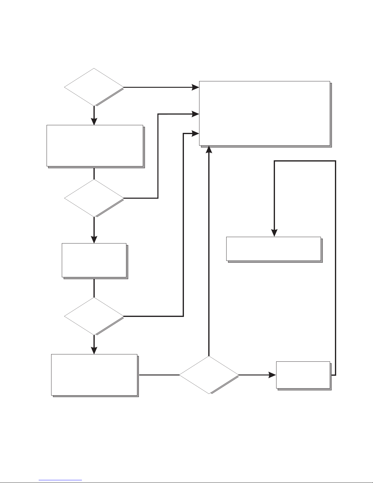
84 IBM xSeries 130: User’s Reference
Server Support
After you register and profile, you will be able to:
• Diagnose problems using the IBM Online Assistant
• Participate in the IBM discussion forum
• Receive e-mail notifications of technical updates
related to your profiled products
Register at:
Profile at:
http://www.ibm.com/pc/register
http://www.ibm.com/pc/support
Register and profile your server
Ye s
No
No
Phone an
IBM HelpCenter
Use the troubleshooting
information provided with
your server to determine
the cause of the problem
and the action to take.
Flash the latest levels of BIOS,
service processor, diagnostics,
and RAID code.
You can download this code at:
http://www.ibm.com/pc/support
No
No
Ye s
Ye s
Ye s
Check all cables for loose connections
and verify that all optional devices you
installed are on the ServerProven list.
You can view the ServerProven list at:
®
http://www.ibm.com/pc/compat
Server working
properly?
Problem
solved?
Problem
solved?
Problem
solved?
You can view the HelpCenter phone
numbers in the Support Phone List at:
http://www.ibm.com/pc/support
Page 99

Chapter 7. Solving problems 85
POST
When you turn on the appliance server, it performs a series of tests to check the
operation of appliance server components and some of the options that are installed
in the appliance server. This series of tests is called the power-on self-test, or POST.
If POST finishes without detecting any problems, a single beep sounds, and the first
screen of your operating system or application program appears.
If POST detects a problem, more than one beep sounds, and an error message
appears on your screen. See “POST beep code descriptions” and “POST error
messages” on page 88 for more information.
Notes:
1. If you have a power-on password set, you must type the password and press
Enter, when prompted, before POST will continue.
2. A single problem might cause several error messages. When this occurs, work to
correct the cause of the first error message. After you correct the cause of the first
error message, the other error messages usually will not occur the next time you
run the test.
POST beep code descriptions
Beep codes are sounded in a series of long and short beeps. The possible types of
beep codes that your appliance server might emit include the following:
No beeps
If no beep occurs after your appliance server completes POST, call for
service.
Continuous beep
Your startup (boot) microprocessor has failed, or your system board or
speaker subsystem might contain a failing component. If the system
continues through POST with no errors, call for service. If no video appears,
the startup processor has failed; replace the startup processor.
One short beep
One beep indicates that your appliance server successfully completed POST.
POST detected no configuration or functional errors. One beep also occurs
after your appliance server completes POST if you type an incorrect power-on
password.
Two short beeps
POST encountered an error. The Configuration/Setup Utility program will
display additional information; follow the instructions that appear on the
screen. See “POST error messages” on page 88 for descriptions of the text
messages that might appear.
Three short beeps
A system memory error has occurred. This combination occurs only if the
video basic input/output system (BIOS) cannot display the error message.
Replace the failing memory module.
Page 100

86 IBM xSeries 130: User’s Reference
Repeating short beeps
The system board might contain a failing component, your keyboard might be
defective, or a key on the keyboard might be stuck. Running the diagnostic
tests can isolate the appliance server component that failed, but you must
have your system serviced. If the error message remains, call for service.
Ensure that:
• Nothing is resting on the keyboard and pressing the key.
• No key is struck.
• The keyboard cable is connected correctly to the keyboard and to the
correct connector on the serve.
Note: If you just connected a new mouse or other pointing device, turn off
the appliance server and disconnect that device. Wait at least 5
seconds; then, turn on the appliance server. If the error message goes
away, replace the device.
Running the diagnostic tests can isolate the appliance server component
that failed, but you must have your system serviced. If the error message
remains, call for service.
One long and one short beep
POST encountered an error on a video adapter. If you are using the
integrated video controller, call for service. If you are using an optional video
adapter, replace the failing video adapter.
One long and two short beeps
A video I/O adapter ROM is not readable, or the video subsystem is defective.
If you hear this beep combination twice, both the system board and an
optional video adapter have failed the test. This beep combination might also
indicate that the system board contains a failing component.
One long and three short beeps
The system-board video subsystem has not detected a monitor connection to
the appliance server. Ensure that the monitor is connected to the appliance
server. If the problem persists, replace the monitor.
Two long and two short beeps
POST does not support the optional video adapter. This beep combination
occurs when you install a video adapter that is incompatible with your
appliance server. Replace the optional video adapter with one that the
appliance server supports, or use the integrated video controller.
POST beep codes
This section contains the POST beep codes for your appliance server. Your server
might omit beep codes that are described in the following table. For example, a 1-2-3
beep code is one beep, a pause, two consecutive beeps, another pause, and then
three more consecutive beeps.
 Loading...