

Page 1

Enterprise Server S80
pSeries 680 Model S85
User’s Guide
SA38-0557-01
IBM
Page 2

Second Edition (November 2000)
Before using this information and the product it supports, read the information in “Safety Notices” on page xi,
“Appendix A. Environmental Notices” on page 197, and “Appendix B. Notices” on page 199.
© International Business Machines Corporation, 1999, 2000. All rights reserved.
Note to U.S. Government Users Restricted Rights--Use, duplication or disclosure restricted by GSA ADP Schedule
Contract with IBM Corp.
Page 3

Contents
Safety Notices ........................xi
Electrical Safety........................xi
Laser Safety Information ....................xiii
Data Integrity and Verification ..................xv
About This Book ......................xvii
ISO 9000 .........................xvii
Online Publications ......................xvii
Related Publications......................xvii
Trademarks ........................xviii
Chapter 1. System Introduction ..................1
System Rack .........................2
I/ORack..........................4
I/ODrawers.........................5
10EIAUnitI/ODrawer....................5
Input/Output Connectors .....................6
10EIAUnitI/ODrawer....................6
Chapter 2. Using the System ...................9
Operator Panel and Power Control .................9
Powering On the System ....................10
Powering Off the System ....................10
POST Indicators .......................12
POST Keys .........................1313
Console Strategy .......................14
Reading the System Rack Operator Panel Display ............14
I/O Drawer Indicator Panels ...................15
10 EIA Unit I/O Drawer Indicator Panel ...............15
Using the Keyboards ......................17
Using the Three-Button Mouse ..................19
Handling the Mouse Correctly ..................20
Caring for the Mouse.....................20
Cleaning the Mouse .....................21
Using the 3.5-Inch Diskette Drive..................22
Diskette Compatibility ....................22
Write-Protecting 3.5-Inch Diskettes ................22
Loading and Unloading the 3.5-Inch Diskette .............23
General Information for 5.0GB 8-mm Tape Drive.............24
Recommendations .....................24
Types of 8-mm Tape Cartridges .................24
Tape Cartridge Compatibility ..................25
Setting the Write-Protect Tab on 8-mm Tape Cartridges .........25
Environmental Considerations for 8-mm Data Cartridges .........26
Operating in Harsh Environments.................26
8-mm Data Cartridge Erasure ..................26
iii
Page 4

Tape Cartridge Data Efficiency .................27
Using the 5.0GB 8-mm Tape Drive .................28
Status Lights .......................28
Status Light States .....................28
Loading the 8-mm Tape Cartridge ................29
Unloading the 8-mm Tape Cartridge ................30
Cleaning the Tape Path on the 5.0GB 8-mm Tape Drive .........30
General Information for 4.0GB 4-mm Tape Drive.............32
Recommendations .....................32
Types of 4-mm Tape Cartridges .................33
Tape Cartridge Compatibility ..................33
Setting the Write-Protect Tab on 4-mm Tape Cartridges .........34
Environmental Considerations for 4-mm Data Cartridges .........34
Operating in Harsh Environments.................35
4-mm Data Cartridge Erasure ..................35
Tape Cartridge Data Capacity ..................35
Using the 4.0GB 4-mm Tape Drive .................36
Status Lights .......................36
Status Light States .....................36
Loading the 4-mm Tape Cartridge ................38
Unloading the 4-mm Tape Cartridge ................39
Cleaning the Tape Path on the 4.0GB 4-mm Tape Drive .........40
Using the CD-ROM Drive ....................42
Loading the CD-ROM Drive ..................42
Unloading the CD-ROM Drive ..................42
Cleaning the CD-ROM Drive ..................43
Emergency Eject ......................43
Using the Hot Swap Disk Drives ..................44
Relationship of AIX Prompts and Physical Drive Location .........44
10 EIA Unit I/O Drawer Locations.................44
Handling Guidelines .....................45
Labels .........................45
Disk Drive Status Light States..................46
Removing and Inserting Disk Drives.................47
Unconfiguring (Removing) or Configuring a Disk Drive..........47
Unconfiguring .......................47
Configuring ........................47
Inserting a Disk Drive into the Hot-Swap Bays ............48
Removing Disk Drives from the Hot-Swap Bays ............52
Ergonomic Information .....................54
Using the Service Processor and Electronic Electronic Service Agent Features . . 55
Service Processor......................55
Electronic Service Agent ...................56
Chapter 3. Service Processor Menus................57
Service Processor Menus ....................59
How to Access Service Processor Menus Locally ...........59
How to Access the Service Processor Menus Remotely .........59
How to Save and Restore Service Processor Settings ..........59
How to return to the service processor menus ............60
iv S80 and S85 User’s Guide
Page 5

Menu Inactivity .......................60
General User Menus ......................61
Privileged User Menus .....................63
MainMenu........................63
Service Processor Setup Menu .................65
Passwords ........................66
System Power Control Menu ..................69
System Information Menu ...................70
Language Selection Menu ...................72
Call-In/Call-Out Setup Menu ..................73
Modem Configuration Menu ..................74
Serial Port Selection Menu ...................75
Serial Port Speed Setup Menu .................75
Telephone Number Setup Menu .................76
Call-Out Policy Setup Menu ..................77
Customer Account Setup Menu .................78
Reboot/Restart Policy Setup Menu ................79
Boot Mode Menu ......................80
Service Processor Procedures in Service Mode .............81
Service Processor Functions ...................82
System Power-On Methods ...................83
Service Processor Call-In Security .................84
Service Processor Reboot/Restart Recovery ..............85
Boot (IPL) Speed ......................85
Failure During Boot Process ..................85
Failure During Normal System Operation ..............85
Service Processor Reboot/Restart Policy Controls ...........86
Configure/Deconfigure Processors .................88
Processor Deconfiguration During Boot...............88
Service Processor System Monitoring - Surveillance ...........89
System Firmware Surveillance..................89
Operating System Surveillance .................89
Call-Out (Call-Home) ......................91
Console Mirroring .......................92
System Configuration ....................92
Service Processor Error Logs ...................93
System POST Errors ......................93
LCD Progress Indicator Log ...................94
Chapter 4. System Management Services ..............95
Text-Based System Management Services ..............95
Password Utilities ......................96
Display Error Log ......................97
Remote Initial Program Load Setup ................98
SCSI Utilities .......................101
Select Console ......................101
MultiBoot ........................102
Select Language......................105
OK Prompt........................105
Exiting System Management Services...............105
Contents v
Page 6

Chapter 5. Using the Online and Standalone Diagnostics ........107
Standalone and Online Diagnostics Operating Considerations ........107
Selecting a Console Display ..................107
Identifying the Terminal Type to the Diagnostics ...........108
Undefined Terminal Types...................108
Running Standalone Diagnostics ................108
Running Online Diagnostics ..................109
Running the Diagnostics from a TTY Terminal ............109
General Attributes Always Required ...............110
Additional Communication Attributes ...............112
Additional Keyboard Attributes .................113
Additional Printer Attributes ..................114
Online Diagnostics Modes of Operation ...............115
Service Mode .......................115
Running the Online Diagnostics in Service Mode ...........115
Concurrent Mode......................116
Running the Online Diagnostics in Concurrent Mode ..........116
Maintenance Mode .....................117
Running the Online Diagnostics in Maintenance Mode .........117
Standalone Diagnostic Operation .................118
Running the Standalone Diagnostics ...............118
Logical and Physical Locations ..................119
Physical Location Codes ....................119
Location Code Format ....................119
AIX Location Codes......................120
AIX and Physical Location Code Reference Tables ..........122
Chapter 6. Introduction to Tasks and Service Aids ..........141
Tasks ..........................142
Add Resource to Resource List ..................144
AIX Shell Prompt ......................144
Analyze Adapter Internal Log...................144
Backup and Restore Media ...................144
Certify Media ........................145
Change Hardware Vital Product Data ................145
Configure Dials and LPFKeys ..................146
Configure Reboot Policy ....................146
Configure Remote Maintenance Policy ...............148
Configure Ring Indicate Power On Policy...............150
Configure Surveillance Policy ..................150
Create Customized Configuration Diskette ..............151
Delete Resource from Resource List ................151
Disk Maintenance ......................152
DisktoDiskCopy.....................152
Display/Alter Sector .....................152
Display Configuration and Resource List ...............153
Display Firmware Device Node Information ..............153
Display Hardware Error Report ..................153
Display Hardware Vital Product Data ................153
Display Machine Check Error Log .................153
vi S80 and S85 User’s Guide
Page 7

Display Microcode Level ....................154
Display or Change Bootlist ...................154
Display or Change Diagnostic Run Time Options ............154
Display Previous Diagnostic Results ................155
Display Resource Attributes ...................155
Display Service Hints .....................155
Display Software Product Data ..................156
Display System Environmental Sensors ...............156157
Display Test Patterns .....................157
Download Microcode .....................158
Download Microcode to PCI SCSI RAID Adapter ...........158
Download Microcode to Disk Drive Attached to a PCI SCSI RAID Adapter 158
Download Microcode to a PCI FC-AL Adapter ............158
Download Microcode to Other Devices ..............159
Fibre Channel RAID Service Aids .................159
Flash SK-NET FDDI Firmware ..................160
Format Media........................160
Hardfile Attached to SCSI Adapter (non-RAID) ............160
Hardfile Attached to PCI SCSI RAID Adapter ............162
Optical Media .......................162
Diskette Format ......................162
Generic Microcode Download ..................163
Local Area Network Analyzer...................163
Log Repair Action ......................163
Periodic Diagnostics .....................164
PCI RAID Physical Disk Identify..................164
Process Supplemental Media ..................164
Run Diagnostics .......................165
Run Error Log Analysis ....................165
Run Exercisers .......................165
Exerciser Commands (CMD)..................165
Acronyms ........................166
Memory Exerciser .....................166
Save or Restore Hardware Management Policies ............167
SCSI Bus Analyzer ......................167
SCSI Device Identification and Removal ...............168
SCSD Tape Drive Service Aid ..................169
Spare Sector Availability ....................170
SSA Service Aids ......................170
Update Disk Based Diagnostics ..................170
Update System or Service Processor Flash ..............171
7135 RAIDiant Array Service Aid .................171172
7318 Serial Communications Network Server Service Aid .........172
Chapter 7. Using the System Verification Procedure ..........173
Step 1. Considerations before Running ThisProcedure ..........173
Step 2. Loading the Diagnostics..................174
Step 3. Running System Verification ................175
Step 4. Additional System Verification ................175
Step 5. Stopping the Diagnostics .................175
Contents vii
Page 8

Chapter 8. Hardware Problem Determination ............177
Problem Determination Using the Standalone or Online Diagnostics......177
Step 1. Considerations before Running This Procedure ..........177
Step 2 ..........................177
Step 3 ..........................178
Step 4 ..........................178
Step 5 ..........................179
Step 6 ..........................179
Step 7 ..........................180
Step 8 ..........................180
Step 9 ..........................180
Step 10 ..........................181
Step 11 ..........................182
Step 12 ..........................183
Step 13 ..........................183
Step 14 ..........................184
Step 15 ..........................184
Step 16 ..........................185
Step 17 ..........................185
Problem Determination When Unable to Load Diagnostics .........186
Step 1. Considerations before Running This Procedure ..........186
Step 2 ..........................186
Step 3 ..........................186
Step 4 ..........................187
Step 5 ..........................188
Step 6 ..........................190
Step 7 ..........................190
Error Codes ........................191
Appendix A. Environmental Notices................197
Product Recycling and Disposal..................197
Environmental Design .....................197
Unit Emissions.......................197
Appendix B. Notices .....................199
Appendix C. Supplies.....................201
Appendix D. Operator Panel Functions ..............203
System Rack Operator Panel ..................203
Function Code Table .....................204
Operator Panel Function Descriptions ................206
Values for IPL Types and Speeds ................206
Function 01 - Display Selected IPL Type, Mode and Speed .......207
Function 02 - Select IPL Type, Mode and Speed ...........207
Function 03 - Start IPL....................208
Function 04 - Lamp Test ...................208
Function 05 - SPCN (System Power Control Network) Informational SRC . . . 208
Function 07 - Restore System Power and Perform Concurrent Maintenance
Repair ........................208
viii S80 and S85 User’s Guide
Page 9

Function 08 - Fast Power Off..................209
Functions 11 to 19 - System Reference Code ............209
Appendix E. Firmware Update Procedures .............211
Determining the Firmware Levels .................211
Obtaining the Firmware Update Package...............212
Downloading Firmware Updates..................213
Appendix F. Service Processor Setup and Test............215
Service Processor Setup Checklist .................215
Testing the Service Processor Setup ................216
Call-In .........................216
Call-Out.........................217
Serial Port Configuration ...................217
Appendix G. Modem Configurations ...............219
Sample Modem Configuration Files ................219219
Configuration File Selection ...................220
Examples For Using the Generic Sample Modem Configuration Files ....221
Customizing the Modem Configuration Files.............221
IBM 7852-400 DIP Switch Settings ................222
Terminal Emulators .....................222
Recovery Procedures ....................222
Seamless Transfer of a Modem Session ...............223
Recovery Strategy .....................224
Prevention Strategy .....................224
Modem Configuration Samples ..................225
Sample File modem_z.cfg...................225
Sample File modem_z0.cfg ..................228
Sample File modem_f.cfg ...................231
Sample File modem_f0.cfg ..................234
Sample File modem_f1.cfg ..................237
Sample File modem_m0.cfg ..................240
Sample File modem_m1.cfg ..................243
Appendix H. High Availability Cabling ...............247
Configuring the HA - 7017 Cluster Server System With No Single Points of Failure 247
Base HA - 7017 Cluster Server System Cabling ............249
Cabling For System Consoles and Cluster Administration Workstations.....249
HA Cluster Server with ASCII System Console ............250
HA Cluster Server With Graphical System Console ..........251
HA Cluster Server Graphical Cluster Administration Workstation ......252
Base HA - 7017 Cluster Server Heartbeat Connections ..........253
SSA Cabling Connections....................254
SSA From Cluster Servers to Double Looped 7133 ..........254
Base HA Cluster Server AC Power Connections ............255
Index ..........................257
Reader’s Comments — We’d Like to Hear From You..........261
Contents ix
Page 10

x S80 and S85 User’s Guide
Page 11

Safety Notices
A
danger
notice indicates the presence of a hazard that has the potential of causing
death or serious personal injury.
Danger
notices appear on the following pages:
v xi
v xii
A
caution
notice indicates the presence of a hazard that has the potential of causing
moderate or minor personal injury.
Caution
notices appear on the following pages:
v xii
v xii
v xiii
v 42
For a translation of the safety notices contained in this book, see the
System Unit
Safety Information
, order number SA23–2652.
Electrical Safety
Observe the following safety instructions any time you are connecting or disconnecting
devices attached to the workstation.
DANGER
An electrical outlet that is not correctly wired could place hazardous voltage
on metal parts of the system or the devices that attach to the system. It is the
responsibility of the customer to ensure that the outlet is correctly wired and
grounded to prevent an electrical shock.
Before installing or removing signal cables, ensure that the power cables for
the system unit and all attached devices are unplugged.
When adding or removing any additional devices to or from the system,
ensure that the power cables for those devices are unplugged before the
signal cables are connected. If possible, disconnect all power cables from the
existing system before you add a device.
Use one hand, when possible, to connect or disconnect signal cables to
prevent a possible shock from touching two surfaces with different electrical
potentials.
During an electrical storm, do not connect cables for display stations, printers,
telephones, or station protectors for communication lines.
xi
Page 12

CAUTION:
This product is equipped with a three–wire power cable and plug for the user’s
safety. Use this power cable with a properly grounded electrical outlet to avoid
electrical shock.
DANGER
To prevent electrical shock hazard, disconnect the power cable
CAUTION:
This unit has more than one power supply cord. To reduce the risk of electrical
shock, disconnect two power supply cords before servicing.
xii S80 and S85 User’s Guide
Page 13

Laser Safety Information
The optical drive in this system unit is a laser product. The optical drive has a label that
identifies its classification. The label, located on the drive, is shown below.
The optical drive in this system unit is certified in the U.S. to conform to the
requirements of the Department of Health and Human Services 21 Code of Federal
Regulations (DHHS 21 CFR) Subchapter J for Class 1 laser products. Elsewhere, the
drive is certified to conform to the requirements of the International Electrotechnical
Commission (IEC) 825 (1st edition 1984) and CENELEC EN 60 825:1991 for Class 1
laser products.
CAUTION:
A class 3 laser is contained in the device. Do not attempt to operate the drive
while it is disassembled. Do not attempt to open the covers of the drive as it is
not serviceable and is to be replaced as a unit.
Class 1 laser products are not considered to be hazardous. The optical drive contains
internally a Class 3B gallium-arsenide laser that is nominally 0.14 milliwatts at 765 to
815 nanometers. The design incorporates a combination of enclosures, electronics, and
redundant interlocks such that there is no exposure to laser radiation above a Class 1
level during normal operation, user maintenance, or servicing conditions.
CLASS 1 LASER PRODUCT
LASER KLASSE 1
LUOKAN 1 LASERLAITE
APPAREIL A LASER DE CLASSE 1
IEC 825:1984 CENELEC EN 60 825:1991
Preface xiii
Page 14

xiv S80 and S85 User’s Guide
Page 15

Data Integrity and Verification
IBM computer systems contain mechanisms designed to reduce the possibility of
undetected data corruption or loss. This risk, however, cannot be eliminated. Users who
experience unplanned outages, system failures, power fluctuations or outages, or
component failures must verify the accuracy of operations performed and data saved or
transmitted by the system at or near the time of the outage or failure. In addition, users
must establish procedures to ensure that there is independent data verification before
relying on such data in sensitive or critical operations. Users should periodically check
the IBM support websites for updated information and fixes applicable to the system and
related software.
xv
Page 16

xvi S80 and S85 User’s Guide
Page 17

About This Book
This book provides information on how to install and remove options, use the system,
use diagnostics, use service aids, and verify system operation. This book also provides
information to help you solve some of the simpler problems that might occur.
ISO 9000
ISO 9000 registered quality systems were used in the development and manufacturing
of this product.
Online Publications
RS/6000 and p Series publications are available online. To access the online books,
visit our Web site at: http://www.rs6000.ibm.com/resource/hardware_docs/
Related Publications
The following publications are available:
v The Enterprise Server S80 Installation Guide, SA38-0582, contains information on
how to set up and cable the system, install and remove options, and verify system
operation.
v The Enterprise Server S80 Service Guide, SA38-0558, contains reference
information, maintenance analysis procedures (MAPs), error codes, removal and
replacement procedures, and a parts catalog.
v The
Diagnostic Information for Multiple Bus Systems
, SA38-0509, contains diagnostic
information, service request numbers (SRNs), and failing function codes (FFCs).
v The
Adapters, Devices, and Cable Information for Multiple Bus Systems
, SA38-0516,
contains information about adapters, devices, and cables for your system. This
manual is intended to supplement the service information found in the
Diagnostic
Information for Multiple Bus Systems
.
v The
Site and Hardware Planning Information
, SA38-0508, contains specifications to
help you do space and environmental planning before your system is installed.
v The
PCI Adapter Placement Reference
, SA38-0538, contains information about slot
requirements for installing PCI adapters. This book is intended to be used to help
plan and install PCI adapters for maximum performance from your system.
v The
High Availability Cluster Multi-Processing for AIX, Version 4.3: Enhanced
Scalability Installation and Administration Guide
, SC23-4284, is needed for
HACMP/ES planning information.
v The
High Availability Cluster Multi-Processing for AIX, Version 4.3: Planning Guide
,
SC23-4277, is needed for HACMP/ES planning information.
v The
7133 SSA Disk System: Operator Guide
describes: how to operate the 7133
SSA Disk System and how to install or replace disk drives to the system, and how to
deal with problems encountered when using the system.
xvii
Page 18

v The
7133 SSA Disk Subsystem: Service Guide
is used by the service technician to
repair system failures in the 7133 SSA Disk System.
Trademarks
The following terms are trademarks of International Business Machines Corporation in
the United States, other countries, or both:
v AIX
v IBM
v RS/6000
v SP
Other company, product, and service names may be trademarks or service marks of
others.
xviii S80 and S85 User’s Guide
Page 19

Chapter 1. System Introduction
The Enterprise Server S80 and p Series 680 Model S85 systems are 64-bit, symmetric
multiprocessing (SMP) enterprise servers. The systems provide the power, capacity and
expandability to support evolution of your business into the 64-bit computing
environment while still supporting the existing 32-bit applications. The I/O subsystem
supports both 32-bit and 64-bit standard PCI adapters.
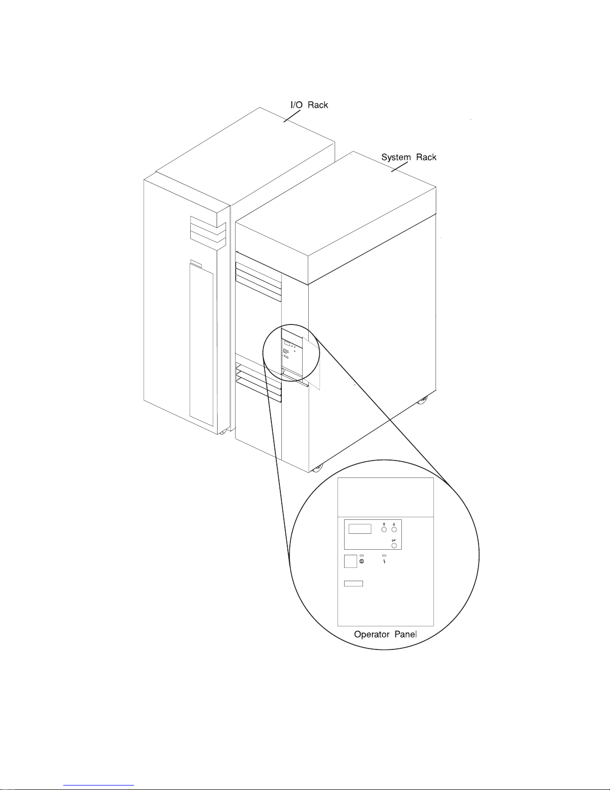
The systems are multi-processor, multi-bus systems packaged in two different rack
types. The processor and memory are packaged in the System Rack. A separate I/O
rack contains the DASD and I/O devices in drawers. The basic system consists of one
System Rack and one I/O Drawer in a separate rack. The systems are expandable to
one System Rack and four I/O Drawers. See the following figure for an example of the
basic system.
System Rack
I/O Rack
1
Page 20

System Rack
The System Rack supports a minimum of one processor card and a maximum of four
processor cards. Each processor card has six 64-bit processors. A maximum of 24
processors may be installed in the system, which shares a common system memory.
The system memory is controlled through a multi-port controller, which supports up to
16 memory slots. The total memory available to users is dependent on the memory
feature card installed and the number of memory cards. All system memory is contained
in the system rack.
Also contained in the System Rack is the operator panel, which provides diagnostic
support in addition to controlling system power. The following figure shows the operator
panel. The System Rack is powered by 200 - 240 V ac.
2 S80 and S85 User’s Guide
Page 21
Chapter 1. System Introduction 3
Page 22
I/O Rack
Each I/O rack holds up to two I/O Drawers. Each I/O Drawer provides up to 14 PCI
adapters per drawer. The primary I/O Drawer (Drawer 0) reserves slots for support of
system media, service processor and hot-pluggable DASD bays resident in the drawer.
For information about PCI adapter slot placement, see
PCI Adapter Placement
Reference
, (SA38-0538). These slots are available in subsequent I/O Drawers 1
through 3 for any supported PCI adapter use. A fully configured system consisting of
four I/O Drawers (with a maximum of two I/O Drawers per I/O rack) and one System
Rack provides support for up to 55 33-Mhz PCI adapters, 48 hot-pluggable SCSI disk
bays and up to 8 media bays. The PCI bus supported is 33-Mhz with both 32 and 64-bit
adapters supported on a per-slot basis. Slots 1, 5, 9, 10 and 14 support either 32 or
64-bit PCI adapters. The remaining slots are 32-bits.
The Service Processor, resident in slot 8 of the primary I/O Drawer, provides extended
service support. The service processor provides facilities for system management, error
data collection, remote call-in, remote call-out including surveillance, and numerous
other features, including password support. The Input/output Rack is powered by 200 240 V ac.
10 EIA Unit I/O Drawer
4 S80 and S85 User’s Guide
Page 23
I/O Drawers
Your system has a 10 EIA Unit I/O Drawer as described below.
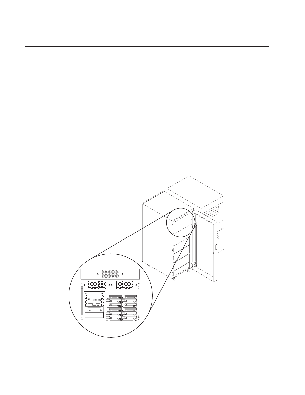
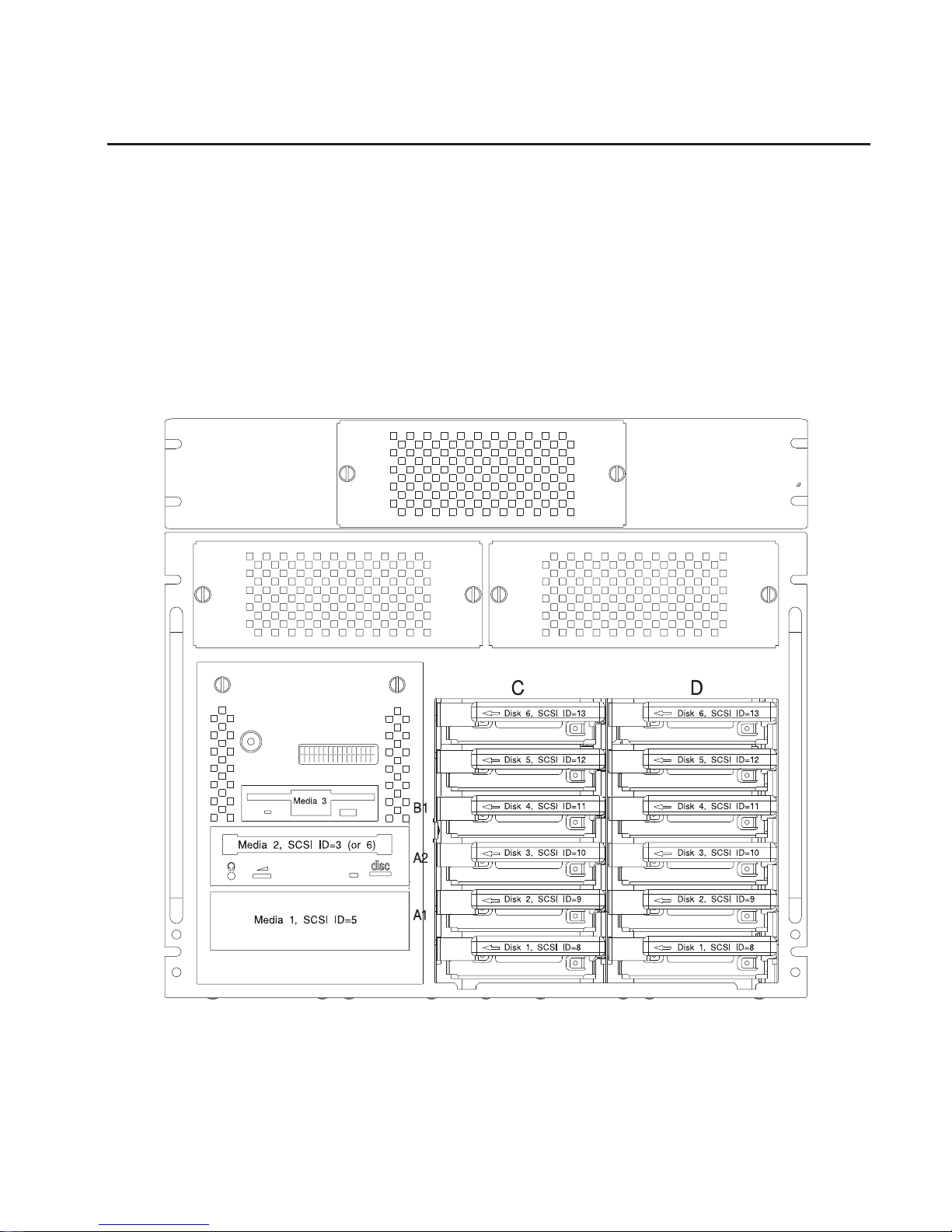
10 EIA Unit I/O Drawer
The 10 EIA Unit I/O Drawer features hot-pluggable disk drive banks shown in the
following figure. Disk drive banks allow system users to insert and remove disk drives
without performing a power down of the system which increases the availability of the
server. The 10 EIA Unit I/O Drawer is powered by 200 - 240 V ac.
The disk drive banks are each able to hold up to six one-inch by 3.5-inch form factor
drives, or three 1.6-inch drives.
When the drawer has the maximum configuration, it holds up to 12 one-inch by 3.5-inch
form factor 16-bit disk drives mounted on carriers and 2 media devices. If the drawer is
fully populated with 1.6-inch disk drives, it holds only 6 disk drives. The disk drives are
mounted in carriers that are auto docking, auto addressing, and hot swappable.
Chapter 1. System Introduction 5
Page 24
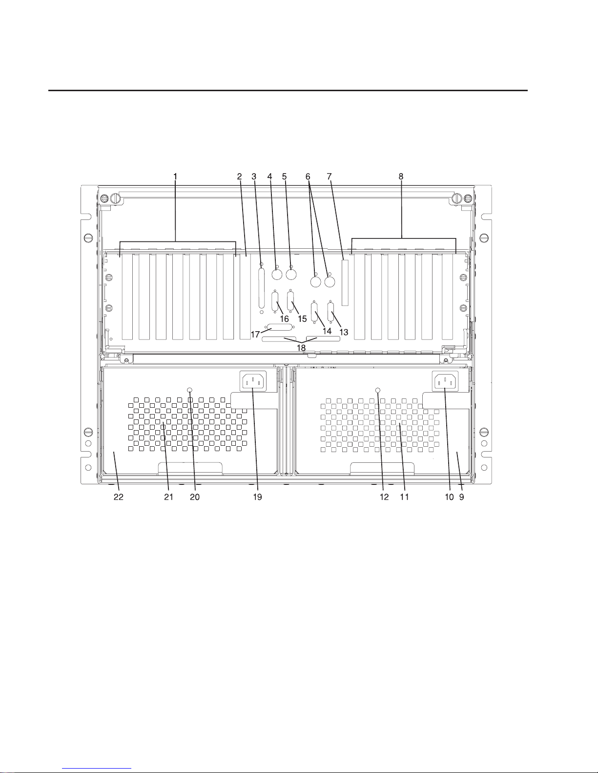
Input/Output Connectors
10 EIA Unit I/O Drawer
The 10 EIA Unit I/O Drawer Input/Output connectors are shown in the following figure.
1. PCI adapter slots (1 - 7)
2. PCI adapter slot 8, service processor card and JTAG cable in primary I/O drawer
(drawer 0)
3. Parallel connector
4. Keyboard connector
5. Mouse connector
6. Reserved
7. SCSI Redrive card (if installed)
8. PCI adapter slots (9 - 14)
9. Right power supply
10. Power cord connector for right power supply
11. Fans (mounted on front end of right power supply)
12. Right power supply, power good LED
6 S80 and S85 User’s Guide
Page 25

13. SPCN2 connector
14. SPCN1 connector
15. Serial port S2
16. Serial port S1
17. Operator panel (OP) connector
18. RIO 0 and RIO 1 connectors
19. Power cord connector for left power supply
20. Left power supply, power good LED
21. Fans (mounted on front end of left power supply)
22. Left power supply.
Chapter 1. System Introduction 7
Page 26

8 S80 and S85 User’s Guide
Page 27

Chapter 2. Using the System
System power control and use of options such as the keyboard, mouse, and drives
supported by the server are discussed in this section.
Operator Panel and Power Control
The following diagram shows the locations of the operator panel display and the
operator panel.
1 Operator Panel Display
2 Scroll Up Pushbutton
3 Scroll Down Pushbutton
4 Enter Pushbutton
5 Attention LED
6 Power On LED
7 Serial Number
8 Power Pushbutton
For more information on operator panel functions, see “Appendix D. Operator Panel
Functions” on page 203.
9
Page 28

Powering On the System
Perform the following steps to power on your system rack and connected I/O Drawers:
1. Open the operator panel cover on the system rack.
2. Press the Power (white) pushbutton on the operator panel.
3. The Power On light on the operator panel starts blinking as the system is powered
on. The light stops blinking and stays on when power on is complete. Likewise, the
green LED on the I/O Drawer(s) starts blinking as the system is powered on. The
light stops blinking and stays on when power on is complete.
For more information, see “System Power-On Methods” on page 83.
Powering Off the System
If the system is operating under AIX, enter the shutdown -F command to power off the
system.
If you cannot use this method, you can power off the system by using the following
operator panel power Pushbutton procedure.
Attention: Using the operator-panel Power pushbutton to power off the system
without first shutting down the operating system may cause unpredictable results in the
data files, and the next IPL takes longer to complete.
1. Open the operator panel cover.
2. Press the Power pushbutton (white) on the operator panel.
The Data/Function display shows O?(the international power-off symbol) with
the ? blinking.
3. Press the Power pushbutton (white) on the operator panel again to confirm.
Note: To cancel the power-off operation, do not press the Power pushbutton a
second time. Instead, press any other operator panel pushbutton.
4. The operator panel Power On light starts blinking as the system powers off. The
operator panel light stops blinking and stays off when the power-off operation is
complete. The green LED on the I/O Drawer(s) goes to a slow blink, indicating the
I/O Drawer power is now on standby.
Does the system power off successfully?
NO Go to Step 5.
Yes This ends the procedure.
5. Perform the following:
a. Press the
or the pushbutton until function 08 is shown in the operator
panel display.
b. Press the Enter pushbutton.
c. SRC A100 8008 is shown on the Data display.
10 S80 and S85 User’s Guide
Page 29

6. Press the Power pushbutton (white) on the operator panel.
The operator panel display shows 08 O ? (the international power-off symbol)
with the ? blinking.
7. Press the Power pushbutton (white) on the operator panel again.
The system powers off, and the Power On light on the system rack operator panel
display goes off and remains off. The green LED on the I/O Drawer(s) goes to a
slow blink, indicating the I/O Drawer power is now on standby.
Note: To cancel the power-off operation, do not select function 08. Instead, press
any other operator panel pushbutton.
For additional information on Function 08 - Fast Power Off, see “Function 08 - Fast
Power Off” on page 209.
Chapter 2. Using the System 11
Page 30

POST Indicators
During the power-on sequence, a series of POST indicators appear on the display.
The following indicators are displayed on the screen.
v Memory
v Keyboard
v Network
v SCSI
v Speaker
If the POST completes successfully, the text displays OK.
The following list describes each of the displayed POST indicators:
Memory
Memory test.
Keyboard
Initialize the keyboard and mouse. The window for pressing a key to bring up
System Management Services is now open. See “POST Keys” on page 13 for
more information.
Network
Self-test on network adapters.
SCSI Adapters are being initialized.
Speaker
Sounds an audible tone at the end of POST.
12 S80 and S85 User’s Guide
Page 31

POST Keys
Numerical 1 Key
The numerical 1 key, when pressed during POST, invokes the System Management
Services (SMS) interface.
Numerical 5 Key
The numerical 5 key, when pressed during POST, invokes the default boot list mode,
located in firmware.
This mode attempts to boot from the first device of each type found in the list. It does
not search for other bootable devices of that type if the first device is not bootable.
Instead, it continues to the next device type in the list. The firmware supports up to five
entries in the boot list.
The default boot order is:
1. Diskette
2. CD-ROM
3. Hard File
4. Tape Drive
5. Network
a. Token Ring
b. Ethernet
Numerical 6 key
The numerical 6 key works like the numerical 5 key, except firmware looks for a boot
record according to the custom bootlist that was set up by System Management
Services.
Numerical 8 key
To enter the Open Firmware command line, press the numerical 8 key
after
the
keyboard POST indicator appears and before the last POST indicator appears during
the startup power-on sequence. After you press the numerical 8 key, the remaining
POST indicators display until initialization completes.
When initialization and power-on self-test (POST) are complete, the Open Firmware
command line (an OK prompt) appears.
The Open Firmware command line is used to set up adapters that are not configurable
with the System Management Services. Your adapter documentation directs you to use
this option if it is needed.
To exit the Open Firmware command line, enter reset-all or power the system down
and reboot.
Chapter 2. Using the System 13
Page 32

Console Strategy
The firmware invokes a console selection sequence at system boot time if any of the
following are true:
v A console has not yet been selected
v A previous console selection sequence timed out
v A change in the system configuration affecting the console (keyboard
installed/removed, mouse installed/removed, graphics adapter installed/removed or
moved to another PCI slot).
The console selection sequence allows the selection (from the appropriate input device)
of any one of all the available console devices. If no console is selected within
approximately 60 seconds, serial port 1 (com1) is selected as the console, and the
selection sequence times out.
Once a console has been selected, the console selection sequence is only invoked at
boot time if there is a change in the system configuration (as described above), or the
contents of the system’s nonvolatile memory (NVRAM) is lost.
Note: Moving an ASCII terminal from one serial port to another (from com1 to com2) is
not detectable by the firmware, so it does not constitute a configuration change.
A system console selection sequence can also be initiated from the SMS menus.
Reading the System Rack Operator Panel Display
The operator panel display is used to:
v Track the progress of the system unit self tests and configuration program.
v Display codes when the operating system comes to an abnormal end.
v Display system messages.
During power-on self-test (POST), 4 and 8 characters display, indicating the progress of
the testing. If an error is detected that requires attention, the system unit halts with up
to a 72-digit number shown 8 digits at a time on the operator panel. This number
identifies the error (see
S80 Installation and Service Guide
for a listing of the error
codes). The attention light turns on to indicate an error condition.
The 4-digit progress codes (checkpoints) are in the form of Ennn, where E is the first
character and n is alphabetic or numeric characters.
The 8-digit progress codes (checkpoints) are in the form of Cnnn nnnn, where C is the
first character and n is alphabetic or numeric.
The locations of the operator panel display and the operator panel are shown in
“Operator Panel and Power Control” on page 9. For details about the operator panel
functions and descriptions, see “Appendix D. Operator Panel Functions” on page 203.
14 S80 and S85 User’s Guide
Page 33

I/O Drawer Indicator Panels
This section describes the indicator panel located on the left front of the 10 EIA Unit I/O
Drawer.
10 EIA Unit I/O Drawer Indicator Panel
1 Power On LED
2 Drawer Indicator Panel Display
10 EIA Unit I/O Drawer and Power Supply LED Status
State of LED Operator Panel LED Right Power Supply
LED
Left Power Supply
LED
Off No power connected No power connected No power connected
On, blinking green System power
connected, not turned
on
System power
connected, not turned
on
System power
connected, not turned
on
On, steady green System power
connected and turned
on
System power
connected and turned
on
System power
connected and turned
on
Chapter 2. Using the System 15
Page 34

10 EIA Unit I/O Drawer Indicator Panel Status
Drawer State LED Drawer Indicator Panel
After Connecting AC Power
Standby Blinking Blinking location U?.?
System power On solid Blinking location U?.?
Receive Firmware Command On solid On solid location Ux.y#
Thereafter On solid On solid location Ux.y#
After Power is Removed Because of a Shutdown
Standby Blinking Blinking location Ux.y
System power Solid Blinking location Ux.y
Receive Firmware Command Solid Solid location Ux.y#
Thereafter Solid Solid location Ux.y#
# represents a blinking asterisk (*)
16 S80 and S85 User’s Guide
Page 35

Using the Keyboards
There are several keyboards available for the system unit. The keyboards have various
keys that enter data and control the cursor location. The keyboards can be engraved for
the languages of different countries.
The functions of each keyboard depend on the software used. The character sets for
the keyboards are contained and explained in the documentation for your operating
system.
The keyboard is divided into four sections:
v Function keys are multipurpose keys, and their function is controlled by the operating
system.
v Typewriter keys are similar to a standard typewriter. Their function is controlled by
the software.
v Control keys move the cursor on the screen and do programmed control functions.
The movement and functions depend upon the application used.
v Numeric keypad is arranged like a calculator to help when typing numbers.
Esc F1 F2 F3 F4 F6 F7 F8F5 F9 F10 F11 F12 Pause
Scroll
Lock
SysRq
Print
Screen
Break
Home
Insert
Page
Up
End
Delete
Page
Down
Num
Lock
/*-
Home Pg Up
789
+
654
PgDn
End
Enter
321
Ins Del
0
.
123
!
@
#
4567
$% &
90
_
-
()
Backspace
+
=
Tab
QWER YUIT OP
Caps
Lock
ASDFGHJKL :
"
;
Enter
,
Shift
ZXCVBNM
,
<
/.
?
>
Shift
Ctrl Alt
*
8
Alt Ctrl
Num
Lock
Caps
Lock
Scroll
Lock
Function Keys
Control
Keys
Typewriter Keys
Numeric
Keypad
Chapter 2. Using the System 17
Page 36

On all of the keyboards, you can adjust the tilt position for typing comfort. To tilt the
keyboard, pull out on the keyboard legs. The legs snap into position. To decrease the
tilt of the keyboard, rotate the keyboard legs until they snap into the bottom of the
keyboard case.
The keyboard cable plugs into the keyboard connector at the rear of the system unit.
18 S80 and S85 User’s Guide
Page 37

Using the Three-Button Mouse
The mouse is a hand-operated locating device. A three-button mouse is available for
use with the system unit.
Consult your application documentation for the exact use of the three-button mouse.
You can use the mouse to perform such functions as positioning a cursor, selecting
items from a menu, or moving around in your document much easier and faster than if
you used only the keyboard. The cursor moves exactly as you move the mouse on a
flat surface, such as a desktop.
When you move the mouse around on a flat surface as shown in this illustration, the
cursor moves on the display screen; the movement changes the position of the cursor.
With the mouse buttons, you can perform functions such as selecting and deselecting
options, extending your selection, or choosing a command. The precise function of your
mouse depends on the software you are using.
Chapter 2. Using the System 19
Page 38

The mouse has a cable that plugs into the mouse connector at the rear of the primary
I/O drawer.
Handling the Mouse Correctly
For best operation, handle the mouse with care. Incorrect handling can damage the
mouse.
Do not:
v Operate the mouse on cloth, unfinished wood, newspaper, or carpet.
v Drop or hit the mouse.
v Carry the mouse by holding onto the cable.
v Expose the mouse to extreme temperatures or direct sunlight.
v Place the mouse in liquid spills.
Caring for the Mouse
The operating surface for the mouse should be smooth, clean, and flat. For example,
you can operate the mouse on the following surfaces:
v Finished wood
v Glass
v Enamel
v Plastic
v Paper (except newspaper)
v Metal
Rough surfaces collect contaminants that can be transferred to the interior of the mouse
by the ball. Rough surfaces can also cause the pads located on the bottom of the
mouse to prematurely wear. A deeply pitted surface could cause erratic operation of the
mouse. The surface you use should be free from spills, dirt, dust, lint, wax, eraser dust,
and other foreign matter. If you experience problems moving the cursor with the mouse:
v Inspect the work surface for spills or other contaminants.
v Dust the work surface.
v If you are using a paper pad, inspect it for wear and replace it if necessary.
20 S80 and S85 User’s Guide
Page 39

Cleaning the Mouse
Use the following procedure to clean the mouse:
1. Remove the retaining ring by turning it counterclockwise.
2. Remove the ball.
3. Inspect the ball for contaminants. Wipe it clean with a dry, lint-free cloth.
4. If the ball is dirty, wash it in warm, soapy water. Rinse and wipe the ball with a
lint-free cloth until dry.
5. Inspect the ball cavity in the mouse for foreign materials. If there are any foreign
materials, remove them.
6. Replace the ball.
7. Replace the retaining ring on the mouse and align it with the open slots in the ball
cavity.
8. Turn the retaining ring clockwise until the open slots are covered and you hear the
ring snap into place.
Retaining Ring
Ball
Cavity
Chapter 2. Using the System 21
Page 40

Using the 3.5-Inch Diskette Drive
Diskette Compatibility
The system unit has a 1.44MB diskette drive installed.
The 1.44MB diskette drive can format, read, and write diskettes compatible with the
following diskette drives:
v 1.0MB diskettes with 720KB formatted data capacity.
v 2.0MB diskettes with 1.44MB formatted data capacity (HD).
Format the diskette according to its specified capacity.
Write-Protecting 3.5-Inch Diskettes
Write-protecting diskettes is necessary so that important information is not accidentally
lost.
When diskettes are write-protected, you can read information from the diskettes, but
you cannot write information to them.
There is a write-protect tab on the 3.5-inch diskette.
To locate the write-protect tab, turn the diskette over with the label facing down.
v To prevent writing onto a diskette, slide the write-protect tab, to open the protect slot.
(Slot Open)
Write-Protect Tab
22 S80 and S85 User’s Guide
Page 41

v To allow writing onto a diskette, slide the write-protect tab to cover the protect slot.
Loading and Unloading the 3.5-Inch Diskette
To load a diskette into the drive, insert the diskette in the diskette drive with the labeled
metal shutter first. Push the diskette into the drive until you hear a click. The click
indicates that the diskette is securely in position in the drive. :artwork.
To unload the diskette, push the diskette-unload button. The diskette unloads partially
from the drive. Remove the diskette. :artwork.
Write-Protect Tab
(Slot Closed)
Chapter 2. Using the System 23
Page 42

General Information for 5.0GB 8-mm Tape Drive
If your system has a 5.0GB 8-mm tape drive, review the following for recommendations
on care and cleaning of your tape drive.
Recommendations
v Use only Data Grade 8-mm tape cartridges. These cartridges are identified by either
a Data, D, or D8 marking on the data cartridge. Use of video grade cartridges can
damage the 8-mm tape drive and can void the warranty of your 8-mm tape drive, and
data written on these tapes may be lost over a short period of time.
v Remove the tape cartridge from the tape drive when it is not in use, and store the
cartridge in the cartridge case.
v Do not open the door on the data tape cartridge. This door covers and protects the
magnetic tape material from dirt, dust, and damage.
v Avoid touching the tape since this can cause loss of data.
v Keep the tape drive door closed except when loading or unloading a tape cartridge.
v Back up and then discard any tape cartridge that repeatedly produces error
messages. The error information is in the system error log.
v Clean the tape path regularly according to the cleaning procedure of the 8-mm tape
drive. Use only recommended cleaning cartridges; other cleaning cartridges can
permanently damage your 8-mm tape drive.
Attention: Do not use video grade cartridges in the 8-mm tape drive. Video grade
tapes may be unreliable and may cause permanent damage to the 8-mm tape drive.
Types of 8-mm Tape Cartridges
v Test Tape Cartridge: This is a specially labeled tape cartridge that is in the media kit
with the 8-mm tape drive. Use this cartridge only when checking the operation of the
drive or running diagnostics; do not use it to save programs or data.
v Data Tape Cartridge: This is a non-labeled blank tape cartridge that is in the media
kit. Use this cartridge for saving your programs or data. The same data tape
cartridge can be used in either a 2.3GB 8-mm tape drive or a 5.0GB 8-mm tape
drive.
v Cleaning Tape Cartridge: Use this cartridge for cleaning the 8-mm tape path. For
more information, see “Cleaning the Tape Path on the 5.0GB 8-mm Tape Drive” on
page 30.
24 S80 and S85 User’s Guide
Page 43

Tape Cartridge Compatibility
The 8-mm tape drive is compatible with existing 8-mm tape subsystems that comply to
the American National Standard (ANSI) X3B5/89-136, Helical-scan Digital Computer
Tape Cartridge, 8-mm for Information Exchange. Data compression effectively increases
the cartridge capacity and data transfer rate for the 5.0GB tape cartridges.
Note: 160 meter cartridges are not processed and are automatically ejected by the
drive.
See the following table for a comparison of different capacity tapes that can be used in
the 5.0GB tape drive:
Format Modes
(C=compression
mode)
8-mm Tape Drive 2.3GB 2.3GB (C) 5.0GB 5.0GB (C)
2.3GB Read/Write
5.0GB Read/Write Read only Read/Write Read/Write
Setting the Write-Protect Tab on 8-mm Tape Cartridges
Setting the write-protect tab on a tape cartridge is necessary so that information is not
accidentally lost. When the write-protect tab of a tape cartridge is set (window open),
information can be read from the tape, but cannot be written to it.
The window on the tape cartridge controls write-protection.
Window
Opened
Window
Opened
Write-Protect Tab Not SetWrite-Protect Tab Not Set Write-Protect Tab SetWrite-Protect Tab Set
Window
Closed
Window
Closed
Chapter 2. Using the System 25
Page 44

Environmental Considerations for 8-mm Data Cartridges
Information in this section describes operating and storage conditions including
temperature, relative humidity, and maximum wet-bulb data.
Attention: The manufacturer has specified a set of temperature and humidity ranges
in which the 8-mm data cartridge can operate with ease. Only regular cleaning
procedures are required when operating the cartridge within this range. The risk of
possible data loss is increased if 8-mm tape cartridges are operated, stored, or shipped
outside the temperature or humidity ranges shown in the following table:
Operating Ranges Storage Shipping
Temperature 16°C to 32°C (60°F to
90°F)
5°C to 32°C (40°F to
90°F)
-40°C to 52°C (-40°F
to 125°F)
Relative Humidity
(non-condensing)
20 to 80% 20 to 80% 5 to 80%
Maximum Wet Bulb 26°C (79°F) 26°C (79°F) 26°C (79°F)
Before using a cartridge, always let it adjust (acclimate) to the operating environment.
Do this by placing the cartridge with its container in the operating environment for as
long as it has been away from this environment or for 24 hours, whichever is less.
Acclimation is necessary for any data cartridge that has been exposed to a different
humidity environment or a temperature change of 11°C or 20°F or more.
Operating in Harsh Environments
The 8-mm tape drive is ideally suited to streaming operations, as opposed to tape
movement operations involving multiple stop/starts and random searches. When the
tape is used for frequent stop-and-start operations, streaming movement is beneficial
and should be used whenever possible. This can be accomplished by ensuring that any
save or restore operation is the only active operation performed by a device connected
to this SCSI I/O controller.
Any tape that has been used outside the ranges specified in the table on page 26 for
an extended period of time (50 passes in 40 hours of nonstop operation) should not be
used as an archival tape. Exposure to the environment deteriorates the magnetic and
physical strength of the tape. Do not store important data on a tape that has been used
outside the specified ranges; transfer the data to a new tape for reliable archiving.
8-mm Data Cartridge Erasure
Most bulk eraser devices do not have the capability to erase 8-mm data cartridges. To
properly erase an 8-mm data cartridge with a bulk eraser device, the erasure rating
must be at least 1500 oersted.
The 2.3GB and the 5.0GB 8-mm tape drives erase residual data before writing new
data on the data tape.
26 S80 and S85 User’s Guide
Page 45

Tape Cartridge Data Efficiency
The 8-mm tape cartridge efficiency is defined as the amount of data that can be stored
on the cartridge. The following variables affect the amount of data that can be stored on
a tape cartridge:
v Size of the data file
v Number of file marks per file
v File mark size used
v Compatibility mode (2.3GB or 5.0GB)
v Media rewrites.
Chapter 2. Using the System 27
Page 46

Using the 5.0GB 8-mm Tape Drive
The optional 5.0GB 8-mm tape drive is a half-height device.
Status Lights
The 5.0GB 8-mm tape drive has two green status lights and one amber status light.
The on and off combinations of the status lights indicate the conditions of the 8-mm
tape drive.
Each of the International Organization for Standards (ISO) symbols located next to a
status light indicates a specific condition of the tape drive as follows:
Status Light States
The following table explains the meaning of the green and amber status lights.
Status Lights on the 5.0GB 8-mm Tape Drive
Status Ready
(green)
Busy
(green)
Disturbance
(amber)
The power-on self-test (POST) is running or the
system has issued a Reset to the drive.
On On On
One of the following has occurred:
v The power is off.
v The POST has completed successfully, but no
tape cartridge has been inserted.
Off Off Off or On
A tape cartridge has been inserted and the 8-mm
tape drive is ready to receive commands from the
system.
On Off Off or On
A tape cartridge has been inserted and the 8-mm
tape drive is performing a tape load or unload
operation.
Off Flashing Off or On
The tape is in motion and the 8-mm tape drive is
busy running a device operation.
On Flashing Off or On
The 8-mm tape drive has detected an internal fault
that requires corrective action. If this occurs, see
note following this table.
Off Off Flashing
The tape path requires cleaning. Refer to “Cleaning
the Tape Path on the 5.0GB 8-mm Tape Drive” on
page 30.
OfforOn Offor
Flashing
On
Unload Button
Status Lights
Ready Green
Busy - Green
Disturbance - Amber
28 S80 and S85 User’s Guide
Page 47

Note: If a fault or an error condition occurs, first try to recover by pressing the unload
button. If this does not correct the fault, switch off the power to the 8-mm tape
drive, and then switch on the power to the drive. If the condition continues, call
your service representative.
Loading the 8-mm Tape Cartridge
Before loading the tape cartridge, make sure the power is on and the write-protect tab
on the tape cartridge is properly set. Refer to “Setting the Write-Protect Tab on 8-mm
Tape Cartridges” on page 25. The tape drive loads the tape from the cartridge and
prepares it for reading and writing.
To load the 8-mm tape cartridge, do the following:
1. Grasp the edges of the 8-mm tape cartridge with the write-protect tab toward you
and the window side of the cartridge facing up.
2. Slide the tape cartridge into the opening on the front of the 8-mm tape drive until
the loading mechanism pulls the cartridge into the drive and the drive door closes.
The ready status light (green) goes on if the load operation was successful.
The 8-mm tape drive is ready for data operations when the tape cartridge is inserted.
After the cartridge is inserted into the tape drive, the tape takes about 25 seconds to
load; this does not interfere with beginning the data operations.
Commands can be entered while the tape is loading. Any commands to the tape drive
start running once the tape has finished loading. Commands not requiring the tape
cartridge are run immediately.
Window Side of
Tape Cartridge
Write-Protect Tab
Ready Status
Light (Green)
8-mm Tape Cartridge
Chapter 2. Using the System 29
Page 48

Unloading the 8-mm Tape Cartridge
Before performing the unload operation, make sure the power to the 8-mm tape drive is
on.
To unload and eject the tape cartridge, press the unload button. The 8-mm tape drive
rewinds the tape and then ejects the tape cartridge from the tape drive.
After you press the unload button, the following occurs:
1. The ready status light goes off.
2. The busy status light flashes during the unload operation.
3. The busy status light goes off when the cartridge is ejected from the tape drive.
The time required for a tape to rewind and unload is between 18 seconds and 3
minutes, depending on the position of the tape when the unload button is pushed.
If the tape cartridge cannot unload and must be removed manually from the drive,
contact your service representative.
Cleaning the Tape Path on the 5.0GB 8-mm Tape Drive
Attention: Do not use video-cleaning cartridges in the 8-mm tape drive.
Video-cleaning cartridges can damage the 8-mm tape drive.
The 8-mm tape path should be cleaned either approximately every 30 hours of tape
motion or once a month, whichever occurs first. The 5.0GB 8-mm tape drive counts the
number of hours of tape motion and indicates when the tape path requires cleaning
when the lighted disturbance status light (amber) is on.
More frequent cleaning may be required if the drive is operated in a dusty environment
or in humid conditions. If the dust is allowed to accumulate, the drive has to perform
more reads and writes. This can cause data loss, and may be prevented by regularly
scheduled cleaning of the drive.
The cleaning cartridge cleans the 8-mm tape drive. If you attempt to use an 8-mm
cleaning cartridge more times than allowed, the tape drive automatically detects the
Unload Button
8-mm Tape Cartridge
Write-Protect Tab
Ready - Green
Disturbance - Amber
Busy - Green
Status
30 S80 and S85 User’s Guide
Page 49

error and ejects the cleaning cartridge. The disturbance status light (amber) remains on
if it was on prior to the cleaning operation being attempted.
Some video cleaning cartridges are extremely abrasive. An 8-mm tape drive may be
permanently damaged after only a few cleaning operations using an abrasive-type
cleaning cartridge.
Before loading the cleaning cartridge, make sure the power to the 8-mm tape drive is
on.
To load the 8-mm cleaning cartridge, do the following:
1. Grasp the edges of the 8-mm cleaning cartridge with the window side of the
cartridge facing up.
2. Slide the cleaning cartridge into the opening on the front of the 8-mm tape drive
until the loading mechanism pulls the cartridge into the drive.
After the 8-mm cleaning cartridge has been fully inserted into the 8-mm tape drive, the
following cleaning operations are performed automatically:
1. The cleaning tape is loaded into the tape path.
2. The drive is cleaned by moving the cleaning tape forward for approximately two
minutes.
3. The tape is unloaded and the cleaning cartridge is ejected from the tape drive when
the cleaning operation is complete.
4. A successful cleaning operation is indicated when the disturbance status light
(amber) goes off.
Window Side of
Tape Cartridge
Disturbance - Amber
Ready - Green
Busy - Green
Status
8-mm Tape Cartridge
Chapter 2. Using the System 31
Page 50

General Information for 4.0GB 4-mm Tape Drive
The 4.0GB 4-mm tape drive is a streaming tape drive that is used to:
v Save and restore system data files.
v Archive important records.
v Distribute operating system software upgrades.
The 4-mm tape drive can be attached to any system using a single-ended interface
meeting the Small Computer System Interface ll (SCSI-ll) Standard ANSI X3.131-199X
Rev. 10h.
The 4-mm tape drive has the following features:
v Capacity of 4.0 GB per cartridge. A capacity of 8 GB is typical with data compression
and with DDS2 data cartridges.
The actual capacity per cartridge varies depending on the application and the type of
data cartridge being used.
v Data transfer rate is 400 KBps. 800 KBps is typical with data compression.
Note: Data compression activated is the default setting from the factory. Data
compression is usually controlled by the application software.
v Read and write of DDS|||| tape cartridges in 2.0 GB per cartridge format.
v A status light that indicates when it is time to clean the tape path.
v Internal diagnostics that are activated when the 4 mm Diagnostic Cartridge is
inserted and loaded into the drive.
v Media recognition system: only data grade media can be written with this tape drive.
The 4-mm tape drive uses a 4-mm data cartridge for saving and restoring your system
data. The 4-mm tape drive writes and reads only 4-mm Digital Data Storage (DDS|||| or
DDS2) cartridges.
Recommendations
Attention: Tape cartridges that do not carry the proper DDS symbol cannot be written
to and their use may cause the 4-mm tape drive to report an error.
v Use only 4-mm Digital Data Storage (DDS|||| or DDS2) cartridges.
Attention: Use of other than recommended cleaning cartridges can damage your
tape drive and voids the drive warranty.
v Clean the tape path by using the recommended cleaning cartridge. Follow the
instructions on the cartridge.
v Back up and then discard any tape cartridge that repeatedly produces error
messages. The error information is in the system error log.
v Do not open the data cartridge door that covers the tape. This door protects the
magnetic tape material from dirt, dust, and damage.
v Do not operate in a dusty environment.
v Do not touch the tape material. Any substance transferred to the tape by touching it
could cause loss of data.
32 S80 and S85 User’s Guide
Page 51

Types of 4-mm Tape Cartridges
The 4-mm tape drive is shipped with three 4-mm cartridges to help start your tape
operations immediately.
4-mm Data Cartridge Use this non-labeled cartridge for saving or restoring your
programs or data. Additional data cartridges can be ordered.
4-mm Diagnostic Cartridge Use this specially labeled cartridge to perform diagnostics on the
drive. Do not use it to save or restore programs or data.
Cleaning Cartridge Use this cartridge for cleaning the 4-mm tape path. For more
information, see “Cleaning the Tape Path on the 4.0GB 4-mm
Tape Drive” on page 40.
Tape Cartridge Compatibility
The 4-mm Tape Drive is compatible with existing 4-mm tape subsystems that are
designed to operate with Digital Data Storage approved media, which meet the
following standards:
v For DDS||||
– American National Standard (ANSI) standard, X3.203-191, Helical-scan Digital
Computer Tape Cartridge, 3.81mm.
– European Computer Manufacturers Association (EMCA) standard, EMCA-150,
3.81mm Wide Magnetic Tape Cartridge and DDS|||| format.
v For DDS2
– European Computer Manufacturers Association (EMCA) standard,
EMCA/TC17/93/20, 3.81mm Wide Magnetic Tape Cartridge for Information
Interchange Helical Scan Recording, DDS2 format.
You cannot change the density setting of the drive, because the device reconfigures
itself automatically, depending on the media type installed, as follows:
Media Type Device Configuration
Non-DDS Read-only
DDS|||| Read/write in 2.0GB mode only
DDS2 Read in either density; write in 4.0GB mode only.
Chapter 2. Using the System
33
Page 52

Setting the Write-Protect Tab on 4-mm Tape Cartridges
The window on the tape cartridge controls write-protection. When the write-protect tab
of a tape cartridge is set (window open), information can be read from the tape, but
cannot be written to it. When the write-protect tab of a tape cartridge is not set (window
closed), information can be both written to and read from the tape. Trying to write to a
4-mm data cartridge while the window is open causes an error.
Environmental Considerations for 4-mm Data Cartridges
Information in this section describes operating and storage conditions including
temperature, relative humidity, and maximum wet bulb data.
Attention: The manufacturer has specified a set of temperature and humidity ranges
in which the 4-mm data cartridge can operate with ease. Only regular cleaning
procedures, as described in “Cleaning the Tape Path on the 4.0GB 4-mm Tape Drive”
on page 40 are required when operating the cartridge within this range. The risk of
possible data loss is increased if 4-mm tape cartridges are operated, stored, or shipped
outside the temperature or humidity ranges shown in the following table.
Before using a cartridge, always let it adjust (acclimate) to the operating environment.
Do this by placing the cartridge with its container in the operating environment for as
long as it has been away from this environment or for 24 hours, whichever is less.
Acclimation is necessary for any data cartridge that has been exposed to a different
humidity environment or a temperature change of 11°C or 20°F or more.
Operating Ranges Storage Shipping
Temperature 16°C to 32°C (60°F to
90°F)
5°C to 32°C (40°F to
90°F)
-40°C to 52°C (-40°F
to 125°F)
Relative Humidity
(non-condensing)
20 to 80% 20 to 80% 5 to 80%
Maximum Wet Bulb 26°C (79°F) 26°C (79°F) 26°C (79°F)
Window
Opened
Window
Opened
Write-Protect Tab Not SetWrite-Protect Tab Not Set Write-Protect Tab Set
Window
Closed
Window
Closed
34 S80 and S85 User’s Guide
Page 53

Operating in Harsh Environments
The 4-mm tape drive is ideally suited to streaming operations, as opposed to tape
movement operations involving multiple stop/starts and random searches. When the
tape is used for frequent stop and start operations, streaming movement is beneficial
and should be used whenever possible. This can be accomplished by ensuring that any
save or restore operation is the only active operation performed by a device connected
to this SCSI I/O controller.
Any tape that has been used outside the ranges specified in the previous table for an
extended period of time (50 passes in 40 hours of nonstop operation) should not be
used as an archival tape. Exposure to the environment deteriorates the magnetic and
physical strength of the tape. Do not store important data on a tape that has been used
outside the specified ranges; transfer the data to a new tape for reliable archiving.
4-mm Data Cartridge Erasure
Most bulk eraser devices do not have the capability to erase 4-mm data cartridges. To
properly erase an 4-mm data cartridge with a bulk eraser device, the erasure rating
must be at least 2000 oersted.
The 4-mm tape drive erases residual data before writing new data on the data tape.
Tape Cartridge Data Capacity
The 4-mm tape cartridge capacity is defined as the amount of data that can be stored
on the cartridge. The following variables affect the amount of data that can be stored on
a tape cartridge:
v Size of the data file
v Number of file marks per file
v Compatibility mode (2GB or 4GB)
v Media rewrites.
Chapter 2. Using the System 35
Page 54

Using the 4.0GB 4-mm Tape Drive
The optional 4.0GB 4-mm tape drive is a half-hight device.
Status Lights
The 4.0GB 4-mm tape drive has two green status lights and one amber status light.
The on and off combinations of the status lights indicate the conditions of the 4-mm
tape drive.
Each of the International Organization for Standards (ISO) symbols located over a
status light indicates a specific condition of the tape drive as follows:
Status Light States
The following tables explain the meaning of the green and amber status lights.
Ready (green) Read-Write (green) Disturbance (amber)
Off No cartridge installed or
error condition
No cartridge or no activity No error condition
Steady Cartridge installed or
loading/unloading
Cleaning required or
media is worn
Flashing Power-on self-test in
progress
Cartridge activity Error condition
4-mm Tape (Front View)
Tape Drive Door
Unload Button
Status Lights
Ready (Green)
Disturbance (Amber)
Read/Write (Green)
36 S80 and S85 User’s Guide
Page 55

Status Lights on the 4.0GB 4-mm Tape Drive
Status Ready
(green)
Read-Write
(green)
Disturbance
(amber)
LED test On 2
seconds at
power on
On 2
seconds at
power on
On 2
seconds at
power on
The power-on self-test (POST) is running or the
Diagnostic Cartridge is running.
Flashing Off Off
One of the following has occurred:
v The power is off.
v The POST has completed successfully, but no
tape cartridge has been loaded.
Off Off Off or On
A tape cartridge has been inserted and the 4-mm
Tape Drive is Ready to receive commands from the
system.
On Off Off or ON
The tape is in motion and the 4-mm Tape Drive is
running a device operation or cleaning.
On Flashing Off or On
The 4-mm Tape Drive has detected an internal error
that requires corrective action such as tape cartridge
failure, high humidity, or no SCSI terminator. Refer
to the service guide or contact your service
representative (see note below).
Off Off Flashing
The tape path requires cleaning or a poor quality
tape cartridge is being used. See “Cleaning the Tape
Path on the 4.0GB 4-mm Tape Drive” on page 40.
OfforOn Offor
Flashing
On
Note: If an error condition occurs, first try to recover by pressing the unload button. If
this does not correct the error, switch off the power to the 4-mm tape drive and
then switch on the power to the drive. If the condition continues, call your service
representative.
Chapter 2. Using the System 37
Page 56

Loading the 4-mm Tape Cartridge
Before loading the tape cartridge, make sure the power is on and the write-protect
switch on the tape cartridge is properly set. Refer to “Setting the Write-Protect Tab on
4-mm Tape Cartridges” on page 34. The tape drive loads the tape from the cartridge
and prepares it for reading and writing.
To load the 4-mm tape cartridge, do the following:
1. Grasp the edges of the 4-mm tape cartridge with the write-protect tab towards you
and the window side of the cartridge facing up.
2. Slide the tape cartridge into the opening on the front of the 4-mm tape drive until
the loading mechanism pulls the cartridge into the drive and the drive door closes.
The ready status light (green) goes on if the load operation was successful.
The 4-mm tape drive is ready for data operations when the tape cartridge is inserted.
After the cartridge is inserted into the tape drive, the tape takes about 15 seconds to
load.
4-mm Tape Cartridge
Write-Protect Tab
Window Side of
Tape Cartridge
Unload Button
Ready Status
Light (Green)
38 S80 and S85 User’s Guide
Page 57

Unloading the 4-mm Tape Cartridge
Before performing the unload operation, make sure the power to the 4-mm tape drive is
on.
To unload and eject the tape cartridge, press the unload button. The 4-mm tape drive
rewinds the tape and then ejects the tape cartridge from the tape drive.
After you press the unload button, the following occurs:
1. The Read-Write status light flashes during the unload operation.
2. The Ready status light and the Read-Write status light turns off when the cartridge
is ejected from the tape drive.
The time required for a tape to rewind and unload is between 10 seconds and 1.5
minutes, depending on the position of the tape when the unload button is pushed.
If the tape cartridge cannot unload and has to be removed manually from the drive,
contact your service representative.
4-mm Tape Cartridge
Unload Button
Write-Protect Tab
Ready Status
Light (Green)
Ready-Write Status
Light (Green)
Chapter 2. Using the System 39
Page 58

Cleaning the Tape Path on the 4.0GB 4-mm Tape Drive
The 4-mm tape path should be cleaned either approximately every 30 hours of tape
motion or once a month, whichever occurs first. The 4-mm tape drive monitors the
recording quality of the tape cartridge and indicates that the tape path requires cleaning
when the disturbance status light (amber) is on.
More frequent cleaning may be required if the drive is operated in a dusty environment
or in humid conditions. If the dust is allowed to accumulate, the drive must perform
more reads and writes. This can cause data loss, and may be prevented by regularly
scheduled cleaning of the drive.
The cleaning cartridge cleans the 4-mm tape drive 50 times before it needs to be
discarded. If you attempt to use a 4-mm cleaning cartridge more than 50 times, the
tape drive automatically detects the error and ejects the cleaning cartridge with the
disturbance status light (amber) remaining on.
Before loading the cleaning cartridge, make sure the power to the 4-mm tape drive is
on.
To load the 4-mm cleaning cartridge, do the following:
1. Grasp the edges of the 4-mm cleaning cartridge with the window side of the
cartridge facing up.
2. Slide the cleaning cartridge into the opening on the front of the 4-mm tape drive
until the loading mechanism pulls the cartridge into the drive.
4-mm Cleaning Cartridge
Window Side of
Cleaning Cartridge
Unload Button
Disturbance Status
Light (Amber)
40 S80 and S85 User’s Guide
Page 59

After the 4-mm cleaning cartridge has been fully inserted into the 4-mm tape drive, the
following cleaning operations are performed automatically:
1. The cleaning tape is loaded into the tape path.
2. The drive is cleaned by moving the cleaning tape forward for approximately 30
seconds.
3. The tape is unloaded and the cleaning cartridge is ejected from the tape drive when
the cleaning operation is complete.
4. A successful cleaning operation is indicated when the disturbance status light
(amber) goes off (if it was activated before the cleaning operation).
If the cleaning cartridge has been used more than 50 times, the disturbance status light
(Amber) flashes.
Chapter 2. Using the System 41
Page 60

Using the CD-ROM Drive
CAUTION:
A Class 3 laser is contained in the device. Do not attempt to operate the device
while it is disassembled. Do not attempt to open the covers of the device, as it is
not serviceable and is to be replaced as a unit.
The CD-ROM is located in bay A of the I/O Drawer. Your CD-ROM drive looks like the
one shown in the illustration, and the controls are located as indicated.
When the CD-ROM is set to On, the status light indicates one of several conditions.
The following are status light states and the respective conditions of the CD-ROM drive:
v Off during standby with the tray loaded or unloaded.
v Blinks from insertion of the tray to completion of initialization.
v Blinks slowly when either the lens or disc is dusty (lens should be cleaned by running
the cleaning disc).
v Blinks fast when in the audio mode.
v Lights during data transfer operations.
v Lights steady when:
– No disc is in the tray.
– The disc is upside down in the tray.
– Some condition exists that should be checked. If this occurs, contact your service
representative.
Loading the CD-ROM Drive
Press the unload button to open the tray. Place the disc, with the printed side away
from the tray, into the tray. Push gently on the load/unload button. The drive
automatically pulls the tray into the drive and prepares the disc for reading.
Unloading the CD-ROM Drive
Push and hold the unload button until the drawer comes out and then remove the disc.
Tray Opening
Emergency
Eject Access
Load/Unload
Button
Status LightVolume Control
Head Phone
Jack
42 S80 and S85 User’s Guide
Page 61

Cleaning the CD-ROM Drive
This CD-ROM drive has an internal head-cleaning mechanism, and therefore does not
require an external cleaning device. The internal cleaning mechanism cleans the head
every time the tray is operated.
Always handle discs carefully by the edges to avoid leaving fingerprints or scratching
the disc. (This helps the disc to maintain good readability.) Discs can be wiped with a
soft, lint-free cloth or lens tissue. Always wipe in a straight line from the inner hub to the
outer rim.
Emergency Eject
Note: Execute the following procedure only in an emergency. For example, the caddy
does not eject when pressing the unload button.
1. Insert a small diameter rod, such as a straightened paper clip, into the emergency
eject hole. (Refer to the illustration below for the location of the emergency eject
hole.)
2. Push in the tool until you feel some resistance.
3. Maintain a small amount of pressure on the rod while pulling on the tray with your
fingernail.
4. Pull the tray open and remove the disc.
Note: Normally the tray makes a ratcheting sound when you pull it open using the
above procedure.
Tray Opening
Emergency
Eject Access
Load/Unload
Button
Status LightVolume Control
Head Phone
Jack
Chapter 2. Using the System 43
Page 62

Using the Hot Swap Disk Drives
The following describes how to install or remove hot-swap disk drives.
v For information on installing a SCSI disk drive, go to page 48.
v For information on removing a SCSI disk drive, go to page 47.
Relationship of AIX Prompts and Physical Drive Location
A SCSI adapter and a SCSI drive address can be displayed on a user display. The AIX
command lsdev -C returns the attached devices on the system display. For more
information, see the documentation for the operating system that controls the system
unit. The following diagram shows the physical locations of the drives.
10 EIA Unit I/O Drawer Locations
The following diagram shows the physical locations of the drives. Up to 12 disk drives
can be installed in banks C and D of each I/O drawer in your system.
44 S80 and S85 User’s Guide
Page 63

Handling Guidelines
The hot-swap disk drive is a sensitive device. Handle the hot-swap carrier and disk
drive with care.
v Do not drop the disk drive or subject the drive to excessive shock.
v Do not expose the disk drive to temperatures lower than -40° F (-40° C) or higher
than 158 ° F (70° C).
v If the drive temperature changes, allow approximately one hour of temperature
acclimatization for every 18° F (10° C) of temperature change.
v Never allow moisture to condense on the drive.
v Static electricity can damage your equipment. Take these precautions to avoid static
electricity damage:
– If you have an antistatic wrist strap available, use it while handling the device.
– Always handle your disk drive carefully.
– Handle the drive by the edges and never touch any exposed circuitry.
– Prevent others from touching the drive.
v Store the hot-swap disk drive in a protective container such as an instrument case or
in a protected area.
v Failure to observe these precautions may lead to product failure, damage, and
invalidation of all warranties.
Labels
Several labels are included in your system ship group which can be attached to the
handle of the hot-swap drive. The labels can be marked in any way to help the users
easily identify the drive for removal or installation.
Chapter 2. Using the System 45
Page 64

Disk Drive Status Light States
The following table explains the meaning of the green and amber status lights and spin
down button.
SCSI Disk Drive Status
Lights
Light or Button Status Definition
Amber On Drive spinning
Off Drive not spinning
Green On Power On
Off Power Off
Blinking Power Off/Drive identify
Spin down Depressed Spin down drive and remove
power
Amber
Green
Spin Down Button
46 S80 and S85 User’s Guide
Page 65

Removing and Inserting Disk Drives
This section provides instructions to help you remove or insert SCSI hot-swap disk
drives into hot-swap bays.
Note: You do not have to power down the system to remove a hot-swappable
assembly from the 10 EIA Unit I/O Drawer. Before you perform these
procedures, take the appropriate actions to back up the data for the drive you
are removing, and that the drive has been removed from the configuration.
Physically removing a hot-swap drive from the 10 EIA Unit I/O Drawer before it
has been removed from the system configuration can cause unrecoverable data
corruption.
Unconfiguring (Removing) or Configuring a Disk Drive
There are three conditions where you need to use these procedures:
v You are removing or installing a drive while the system power is turned on.
v You are installing a new drive.
v You are removing a drive from the system.
Unconfiguring
To unconfigure (remove) a disk drive, do the following:
1. Log in as root.
2. Enter the smit command.
3. Select Devices.
4. Select Fixed Disk.
5. Select Remove a Fixed Disk.
6. Select the disk you want to remove from the list on the screen.
7. For the Keep Definition option, select Yes. This retains the details of the drive in the
device configuration database.
8. Select the Do option to remove the drive.
9. The drive can now be removed from the drawer, return to the procedure that
directed you here.
Configuring
To configure a drive, do the following:
1. Log in as root.
2. Enter the smit command.
3. Select Devices.
4. Select the type of drive you want to configure.
5. Select Add for the type of drive you are configuring, then select the type of drive
you are adding.
6. The drive is ready to use.
Chapter 2. Using the System 47
Page 66

Inserting a Disk Drive into the Hot-Swap Bays
This procedure describes how to insert disk drives into a hot-swap bay while the I/O
Drawer is powered on.
Attention: Caution should be used when handling all hard drives. Drives are more
likely to be damaged during installation and service. Bumping or handling drives roughly
causes latent failures. Do not stack drives, and always use appropriate ESD practices.
A drop of as little as 1/4 inch can cause latent failures. Media can take 30 seconds to
spin down, so ensure at least a 30 second delay after switching off the hot-swappable
drives for removal.
Notes:
1. Disk drive banks support hot-swappable disk drives only.
2. This procedure is similar for any hot-swap disk drive that is supported by this
drawer.
3. For additional information regarding the operation of the hot-swap disk drives, see
the documentation that came with the drives.
4. Remember that each 1.6 inch SCSI disk drive takes two bays.
This section gives the instructions for inserting hot-swap disk drives into the disk drive
banks.
1. To insert a hot-swap disk drive, open the door to the Input/output Rack.
2. Loosen the screws that hold the disk drive cover to the drawer and remove the disk
drive cover from the drawer, storing it in a safe place.
Note: In this illustration, the rack is shown with the door and hinges removed.
Disk Drive
Cover
10 EIA Unit Drawer
48 S80 and S85 User’s Guide
Page 67

3. Each hot-swap disk drive must have a hot-swap disk drive carrier attached.
Attention: Handle the hot-swap disk drive with care, as it is very fragile and can
be easily damaged if exposed to shock, electrostatic discharge, or rough handling.
4. It is recommended that you insert the hot-swap disk drive in the next unused
position of the disk-drive banks, going from bottom to top.
Attention: Attaching SCSI address jumpers on the hot-swap disk drive rather than
using the automatic ID furnished by the backplane is not advised. Attaching jumpers
can cause service problems, multiple drives at the same address, or confusion
locating the correct drive.
a. Rotate the carrier latch to the open position.
b. Position the drive carrier assembly horizontally, with the connector facing into
the bay.
Chapter 2. Using the System 49
Page 68

c. Align the side of the carrier with the raised guides on the left of the bay.
d. Slide the carrier into the bay gently to keep from damaging the hot-swap disk
drive. Slide the carrier to the rear of the bay until it is seated into the connector.
50 S80 and S85 User’s Guide
Page 69

e. Move the carrier latch to the locked position. If the carrier does not lock, check
that the drive carrier is fully seated in the backplane. When the drive carrier is
fully seated and power is turned on, the green LED on the drive carrier
illuminates.
The following table explains the meaning of the green and amber status LEDs and
spin down button on a SCSI disk drive.
Status LEDs
LED or Button Status Definition
Amber On Drive spinning
Off Drive not spinning
Green On Power On
Off Power Off
Blinking Power Off/Drive identify
Spin down Depressed Spin down drive and remove
power
5. If you have other hot-swap disk drives to insert, go to page 49.
6. If you do not have any other procedures to perform, replace the cover that you
removed in step 2 on page 48.
7. Close the Input/output Rack door.
8. Go to “Unconfiguring (Removing) or Configuring a Disk Drive” on page 47 and
configure the disk drive unit you just inserted.
Chapter 2. Using the System 51
Page 70

Removing Disk Drives from the Hot-Swap Bays
This procedure describes how to remove hot-swap disk drives from a hot-swap bay
while the I/O Drawer is powered on.
If you remove a hot-swap disk drive when the I/O Drawer power is off, steps 4 and 5 do
not apply.
Attention: Use caution when handling all hard disk drives. Drives are more likely to
be damaged during installation and service. Bumping or handling drives roughly causes
latent failures. Do not stack drives and always use appropriate ESD (Electro-Static
Discharge) practices. A drop of as little as 6.5 mm (.25 inches) can cause latent
failures. Media can take 30 seconds to spin down, so ensure at least a 30 second delay
has passed after switching off hot-swappable drives for removal.
1. Go to “Unconfiguring (Removing) or Configuring a Disk Drive” on page 47 and
unconfigure the disk drive unit you are removing.
2. Open the Input/output Rack door.
3. Loosen the screws that hold the disk drive cover to the drawer and remove the
disk drive cover from the drawer, storing it in a safe place.
Note: In this illustration, the rack is shown with the door and hinges removed.
Attention: Physically removing a hot-swap drive from the I/O Drawer before it
has been removed from the system configuration, can cause unrecoverable data
corruption.
4. Verify that the device has been removed from the system configuration; the yellow
LED on the hot-swap disk drive should be off.
5. For SCSI disk drives, press the spin down button on the hot-swap disk drive;
observe the green flashing LED.
Disk Drive
Cover
10 EIA Unit Drawer
52 S80 and S85 User’s Guide
Page 71

6. Unlock the drive by turning the carrier latch 90 degrees clockwise to the open
position.
SCSI Disk Drives
7. Disconnect the drive from the connector on the backplane by grasping the handle
on the drive carrier and carefully pulling the drive out of the server.
Attention: Do not open the drive; no user adjustments or serviceable parts are
inside.
8. Place the hot-swap disk drive in a protective container.
9. Replace the disk drive cover that you removed earlier.
10. Close the Input/output Rack door.
Chapter 2. Using the System 53
Page 72

Ergonomic Information
Once you have setup your system, we encourage you to visit the Healthy Computing
web site. Good ergonomic practice is important to get the most from your workstation
and to avoid discomfort. This means that the equipment and the workplace should be
arranged to suit your individual needs and the kind of work you do.
This web site gives ergonomic guidelines to help you understand the ergonomic
considerations that you should know when working at a computer workstation. The
address is:
http://www.us.pc.ibm.com/healthycomputing
54 S80 and S85 User’s Guide
Page 73

Using the Service Processor and Electronic Electronic Service Agent Features
The Service Processor and Electronic Service Agent features protect users against
unnecessary system downtime by keeping support personnel (both internal and
external) aware of any unexpected changes in the system environment. In combination,
the two features provide a flexible solution to automated system maintenance.
Service Processor
The Service Processor runs on its own power boundary and continually monitors
hardware attributes, the AIX Operating System, and the environmental conditions within
the system. Any system failure which prevents the system from coming back to an
operational state (a fully functional AIX Operating System) is reported by the Service
Processor. The Service Processor is controlled by firmware and does not require the
AIX Operating System to be operational to perform its tasks. If any system failures are
detected, the Service Processor has the ability to take predetermined corrective actions.
The methods of corrective actions are:
v Surveillance
v Call Home
v AIX Operating System Monitoring
Surveillance is a function in which the Service Processor monitors the system through
heartbeat communication with the system firmware. The heartbeat is a periodic signal
that the firmware can monitor. During system startup, the firmware surveillance monitor
is automatically enabled to check for heartbeats from the firmware. If a heartbeat is not
detected within a default period, the Service Processor cycles the system power and
attempts to restart until the system either restarts successfully, or a predetermined retry
threshold is reached. In the event the Service Processor is unsuccessful in bringing the
system online (or in the event that the user asked to be alerted to any Service
Processor-assisted restarts), the system can call home to report the error.
The Call Home function can be initialized to call either a service center telephone
number, a customer administration center, or a digital pager telephone number. The
Service Processor can be configured to stop at the first successful call to any of the
numbers listed, or can be configured to call every number provided. If connected to the
service center, the Service Processor transmits the relevant system information (the
system’s serial number and model type) and Service Request Number (SRN). If
connected to a digital pager service, the Service Processor inputs a Customer Voice
Telephone Number defined by the customer. An established sequence of digits or the
telephone number to a phone near the failed system could be used to signal a system
administrator to a potential system failure.
During normal operations, the Service Processor can also be configured to monitor the
AIX Operating System. If AIX does not respond to the Service Processor heartbeat, the
Service Processor assumes the operating system is hung. The service processor can
automatically initiate a restart and, if enabled, initiate the call home function to alert the
appropriate people to the system hang. Enabling Operating System Surveillance also
affords AIX the means to detect any Service Processor failures and report those failures
to the Electronic Service Agent application.
Chapter 2. Using the System 55
Page 74

Unlike the Electronic Service Agent, the service processor cannot be configured in a
client/server environment where one system can be used to manage all dial-out
functionally for a set of systems.
Prior to installing the Service Processor feature, ensure that you have the latest levels
of service processor microcode and system firmware. You also need a properly
configured modem. For more information on configuring a modem, see “Modem
Configuration Menu” on page 74.
Electronic Service Agent
The Electronic Service Agent is a software extension to the AIX Operating System that
monitors the system while the AIX Operating System is running. The Electronic Service
Agent monitors and analyzes all recoverable system failures, and, if needed, can
automatically place a service call to a service center (without user intervention).
The service center receives the machine type/serial number, host name, SRN, and a
problem description. The service center analyzes the problem report and, if warranted,
dispatches a service person to the customer site. The service center also determines if
any hardware components need to be ordered prior to the service person’s arrival.
The Electronic Service Agent code also gives the user the option to establish a single
system as the problem reporting server. A single system, accessible over the user
network, can be used as the central server for all the other systems on the Local Area
Network (LAN) who are running the Electronic Service Agent application. If the
Electronic Service Agent application on a remote client decides a service request needs
to be placed, the client forwards the information to the Electronic Service Agent server
who dials the service center telephone number from its locally attached modem. In this
scenario, the user only needs to maintain a single analog line for providing call-out
capabilities for a large set of servers.
When used in a Scalable Parallel (SP) environment, a client/server type implementation
is configured. The Electronic Service Agent client code runs on each of the SP nodes.
The server component runs on the Control Workstation. In the event of any system
failures, the relevant information is transmitted to the Control Workstation through the
integrated Ethernet. Once alerted to the system failure, the Control Workstation initiates
actions to prepare and send the service request.
A modem is required for enabling automated problem reporting to the IBM service
center. Configuration files for several types of modems are included as part of the
Electronic Service Agent package. Refer to “Modem Configuration Menu” on page 74 for
more information on configuring your modem.
56 S80 and S85 User’s Guide
Page 75

Chapter 3. Service Processor Menus
The service processor menus make it possible for you to configure service processor
options, as well as enable and disable functions.
Service processor menus are available using an ASCII terminal while the system is
powering on or when the service processor has detected a server problem (such as a
surveillance failure).
For a summary of the service processor functions and the methods used to invoke
them, see the following table.
57
Page 76

Service Processor Functions Service
Processor
Menus (ASCII
terminals)
AIX Service
Aids (ASCII or
graphics
terminals)
SMS (ASCII or
graphics
terminals)
Read VPD image from last system boot Y
3
Read System POST Errors Y
3
Read Service Processor Error Logs Y
3
View Progress Indicators from last Boot Y
3
Power-off System Y
2
Read NVRAM Y
2
Start Talk Mode Y
2
Enable/Disable Console Mirroring Y
2
Setup Reboot/Restart Policy Y
2
Y
1
Enable/Disable Modem Y
2
Y
1
Setup Modem Configuration Y
2
Y
1
Setup Dial-out Phone Numbers Y
2
Y
1
Setup Surveillance Y
2
Y
1
Select Modem Line Speed Y
2
Y
1
Update Service Processor Flash EPROM Y
1
Save/Restore Hardware Maintenance Policies Y
1
Change General Access Password Y
2
Change Privileged Access Password Y
2
Y
2
Select Language Y
2
Y
2
Enable/Disable Unattended Start Mode Y
2
Y
1
Y
2
Passwords required (if set):
1
Operating system root password
2
Privileged access password
3
General access (power-on) password
58 S80 and S85 User’s Guide
Page 77

Service Processor Menus
The service processor menus are divided into two groups:
v General user menus - the user must know the general access password.
v Privileged user menus - the user must know the privileged access password.
The following section describes these two groups of menus, how to access them, and
the functions associated with each option.
If the server is powered on, the service processor menus can be accessed locally or
remotely.
How to Access Service Processor Menus Locally
Service processor menus can be accessed locally by connecting an ASCII terminal to
either serial port 1 or 2. Because the presence of the ASCII terminal cannot be
confirmed by the service processor, you must press a key (any key) on the ASCII
terminal to confirm its presence. The key on the ASCII terminal must be pressed during
the time when the operator panel display shows the code E07A.
You can recognize when the access time for the service processor menu begins in the
following ways:
v The checkpoint prior to the access checkpoint is E04F.
v The system beeps three times as it enters checkpoint E07A.
When you gain access, the service processor prompts you for a password (if set), and
when verified, displays the service processor menus.
The service processor menu prompt, represented by 1> or 2> indicates the serial port to
which the terminal is connected. A 1> indicates serial port 1, and 2> indicates serial port
2.
How to Access the Service Processor Menus Remotely
If your system has a modem connected and is configured for call-in (see “Modem
Configuration Menu” on page 74), the service processor menus can be accessed
remotely as follows:
1. With the system powered off, call in from a remote terminal. Wait for at least two
rings and hang up. The system powers on upon detecting ring-indicate, and pauses
for a return call if call-in is enabled.
2. Wait five minutes and call in again. The service processor prompts you for a
password (if set). When verified, the service processor menus display remotely.
How to Save and Restore Service Processor Settings
All the settings you make (except language) from the service processor menus can be
backed up either for recovering from a fault that may corrupt these settings, or for
replicating these settings to other servers that include a service processor.
Chapter 3. Service Processor Menus 59
Page 78

The service aid, Save or Restore Hardware Management Policies, can be used to save
your settings after initial setup or whenever the settings must be changed for system
operation purposes.
It is strongly recommended that this service aid is used for backing up service
processor settings to protect the usefulness of the service processor, and the availability
of the server. Refer to “Save or Restore Hardware Management Policies” on page 167
for information about this service aid.
How to return to the service processor menus
When exiting SP menus using option ″99″, there is a 10-second delay before the
system continues its boot procedure. During that 10 seconds, you may strike a key on
the ASCII terminal to return to the menus and select other options.
During the 10-second delay, an information message appears on the display. After the
10-second delay, the service processor menus are no longer available until either the
next system boot or the service processor regains control due to a system failure.
Menu Inactivity
To prevent loss of control due to power loss or power surges, the service processor
attempts to leave menu mode after 10 minutes of inactivity by simulating the option 99
selection. This attempt is successful on menus containing the ″99″ option. On the other
menus, the attempt is unsuccessful and the following message displays with each
attempt:
Illegal value entered
Press Return to continue
If for some reason you want to hold the server in menu mode, select one of the menus
that does not have the ″99″ option. Boot activity cannot continue if the service
processor is in menu mode, and power losses or surges could result in unpredictable
server responses.
60 S80 and S85 User’s Guide
Page 79

General User Menus
The menu options presented to the general user are a subset of the options available to
the privileged user. The user must know the general access password, if set, to access
these menus.
GENERAL USER MENU
1. Continue System Boot
2. Read VPD Image from Last System Boot
3. Read Progress Indicators from Last System Boot
4. Read Service Processor Error Logs
5. Read System POST Errors
99. Exit from Menus
1>
v Continue System Boot
Allows the user to continue with and monitor the system boot already in progress
using the current ASCII terminal as the active console.
Make this selection if you wish to monitor the IPL progress messages on your
terminal. If you do not wish to monitor the IPL progress messages, select option 99.
Exit from Menus.
v Read VPD Image from Last System Boot
Displays manufacturer vital product data, such as serial numbers, part numbers, and
so on, that were stored from the system boot prior to the one in progress now.
v Read Progress Indicators from Last System Boot
Displays the boot progress indicators (checkpoints), up to a maximum of 100, from
the system boot prior to the one in progress now. This historical information may be
useful to help diagnose system faults.
The progress indicators are displayed in two sections. Above the dashed line are the
progress indicators (latest) from the boot that produced the current sessions. Below
the dashed line are progress indicators (oldest) from the boot preceding the one that
produced the current sessions.
The progress indicator codes are listed top (latest) to bottom (oldest). The dashed
line represents the point where the latest boot started. For an example, refer to “LCD
Progress Indicator Log” on page 94.
v Read Service Processor Error Logs
Displays the service processor error logs. For an example, refer to “Service
Processor Error Logs” on page 93.
v Read System POST Errors
Displays the results of the System Firmware POST (Power-On Self Test). Your server
may be able to start in the presence of POST errors if there are sufficient working
system resources. If POST errors occur during start-up, this error log, when used
with the diagnostics, helps to isolate faults. For an example, refer to “Service
Processor Error Logs” on page 93.
Chapter 3. Service Processor Menus 61
Page 80

v Exit from Menus
Allows the user to continue with the system boot already in progress using the
current ASCII terminal as the active console. Make this selection if you
do not
wish to
monitor the IPL progress messages on your terminal. Exiting from the menus causes
the modems to disconnect, but the boot process continues.
62 S80 and S85 User’s Guide
Page 81

Privileged User Menus
The following menus are available to privileged users only. The user must know the
privileged access password, if set, to access these menus.
Main Menu
At the top of the Main Menu is a listing containing:
v Your service processor’s current firmware version
v The firmware copyright notice
v The system name given to your server during setup
You need the firmware version for reference when you either update or repair the
functions of your service processor.
The system name, an optional field, is the name your server reports in problem
messages. This name helps your support team, (for example, your system
administrator, network administrator, or service representative) to more quickly identify
the location, configuration, and history of your server. The System Name is set from the
Main Menu using option 6.
Chapter 3. Service Processor Menus 63
Page 82

Note: The information under the Service Processor Firmware heading in the Main
Menu illustration that follows is example information only.
Service Processor Firmware
VERSION: 19990707
Copyright 1999 IBM Corporation
SYSTEM NAME
MAIN MENU
1. Service Processor Setup Menu
2. System Power Control Menu
3. System Information Menu
4. Language Selection Menu
5. Call-In/Call-Out Setup Menu
6. Set System Name
99. Exit from Menus
1>
v Service Processor Setup Menu
See “Service Processor Setup Menu” on page 65 for more information.
v System Power Control Menu
See “System Power Control Menu” on page 69 for more information
v System Information Menu
See “System Information Menu” on page 70 for more information.
v Language Selection Menu
See “Language Selection Menu” on page 72 for more information.
v Call-In/Call-Out Setup Menu
See “Call-In/Call-Out Setup Menu” on page 73 for more information.
v Set System Name
Allows setting of the system name.
64 S80 and S85 User’s Guide
Page 83

Service Processor Setup Menu
The service processor setup menu shown below is accessed from the Main menu:
SERVICE PROCESSOR SETUP MENU
1. Change Privileged Access Password
2. Change General Access Password
3. Enable/Disable Console Mirroring:
Currently Enabled
4. Start Talk Mode
5. OS Surveillance Setup Menu
98. Return to Previous Menu
99. Exit from Menus
1>
Note: Unless otherwise stated in menu responses, settings become effective when a
menu is exited using option 98 or 99.
Chapter 3. Service Processor Menus 65
Page 84

Passwords
Passwords can be any combination of up to 8 alphanumeric characters. You can enter
longer passwords, but the entries are truncated to include only the first 8 characters.
The privileged-access password can be set from the service processor menus or from
System Management Services (SMS) utilities (see “Chapter 4. System Management
Services” on page 95). The general-access password can be set only from service
processor menus.
For security purposes, the service processor counts the number of attempts to enter
correct passwords. The results of not recognizing a correct password within this error
threshold are different, depending on whether the attempts are being made locally (at
the server) or remotely (through a modem). The error threshold is 3 attempts.
If the error threshold is reached by someone entering passwords at the server, the
service processor commands the server to resume the initial program load (IPL). This
action is taken based on the assumption that the server is in an adequately secure
location with only authorized users having access. Such users must still successfully
enter a login password to access AIX.
If the error threshold is reached by someone entering passwords remotely, the service
processor commands the server to power down to prevent potential security attacks on
the server by unauthorized remote users. The following illustrates what you can access
with the privileged-access password and the general-access password.
Privileged
Access
Password
General
Access
Password
Resulting Menu
None None Service processor MAIN MENU displayed
None Set Users with the password see the GENERAL USER MENU.
Users without the password see the service processor MAIN
MENU.
Set None Users with the password see the service processor MAIN
MENU. Users without password see the GENERAL USER
MENU.
Set Set Users see menus associated with the entered password
v Change Privileged Access Password
Set or change the privileged-access password. It provides the user with the capability
to access all service processor functions. This password is usually used by the
system administrator or root user.
v Change General Access Password
Set or change the general-access password. It provides limited access to service
processor menus, and is usually available to all users who are allowed to power on
the server, especially remotely.
Note: The general-access password can only be set or changed while the
privileged-access password is set.
66 S80 and S85 User’s Guide
Page 85

v Enable/Disable Console Mirroring
When console mirroring is enabled, the service processor sends information to both
serial ports. This capability can be enabled by local or remote users. This provides
local users the capability to monitor remote sessions. Console mirroring can be
enabled for the current session only. For more information, see “Console Mirroring”
on page 92.
v Start Talk Mode
In a console mirroring session, it is useful for those that are monitoring the session to
be able to communicate with each other. Selecting this menu item activates the
keyboards and displays for such communications while console mirroring is
established. This is a full duplex link, so message interference is possible. Alternating
messages between users works best.
Chapter 3. Service Processor Menus 67
Page 86

v OS Surveillance Setup Menu
This menu can be used to set up operating system (OS) surveillance.
OS Surveillance Setup Menu
1. Surveillance:
Currently Enabled
2. Surveillance Time Interval:
2 minutes
3. Surveillance Delay:
2 minutes
98. Return to Previous Menu
1>
– Surveillance
Can be set to Enabled or Disabled.
– Surveillance Time Interval
Can be set to any number from 2 through 255.
– Surveillance Delay
Can be set to any number from 0 through 255.
Refer to “Service Processor System Monitoring - Surveillance” on page 89 for more
information about surveillance.
68 S80 and S85 User’s Guide
Page 87

System Power Control Menu
This menu can be used to set power control options. Other menus that control boot
options are available here:
SYSTEM POWER CONTROL MENU
1. Enable/Disable Unattended Start Mode:
Currently Enabled
2. Reboot/Restart Policy Setup Menu
3. Continue System Boot
4. Power-Off System
5. Boot Mode Menu
98. Return to Previous Menu
99. Exit from Menus
1>
v Enable/Disable Unattended Start Mode
This option can be used to instruct the service processor to restore the power state
of the server after a temporary power failure. Unattended start mode can also be set
through the System Management Services (SMS) menus. It is intended to be used
on servers that require automatic power-on after a power failure. For more
information, see “System Power-On Methods” on page 83.
v Reboot/Restart Policy Setup Menu
See “Reboot/Restart Policy Setup Menu” on page 79.
v Continue System Boot
Allows the user to continue with and monitor the system boot already in progress
using the current ASCII terminal as the active console.
Make this selection if you wish to monitor the IPL progress messages on your
terminal. If you do not wish to monitor the IPL progress messages, select option 99.
Exit from Menus.
v Power off System
Allows the user to power-off the server.
v Boot Mode Menu
See “Boot Mode Menu” on page 80.
Chapter 3. Service Processor Menus 69
Page 88

System Information Menu
Access to system configuration information, error logs, system resources, and
processor configuration is a available from this menu:
SYSTEM INFORMATION MENU
1. Read VPD Image from Last System Boot
2. Read Progress Indicators from Last System Boot
3. Read Service Processor Error Logs
4. Read System POST Errors
5. Read NVRAM
6. Read Service Processor Configuration
7. Processor Configuration/Deconfiguration Menu
98. Return to Previous Menu
99. Exit from Menus
1>
v Read VPD Image from Last System Boot
Displays manufacturer’s vital product data (VPD), such as serial numbers, part
numbers, and so on, that were stored from the system boot prior to the one in
progress now.
v Read Progress Indicators from Last System Boot
Displays the boot progress indicators (checkpoints), up to a maximum of 100, from
the system boot prior to the one in progress now. This historical information can be
useful to help diagnose system faults.
The progress indicators are displayed in two sections. Above the dashed line are the
progress indicators (latest) from the boot that produced the current sessions. Below
the dashed line are progress indicators (oldest) from the boot preceding the one that
produced the current sessions.
The progress indicator codes are listed top (latest) to bottom (oldest). The dashed
line merely represents the point where the latest boot started. For an example, refer
to “LCD Progress Indicator Log” on page 94.
v Read Service Processor Error Logs
Displays error conditions detected by the service processor. Refer to “Service
Processor Error Logs” on page 93 for an example of this error log.
v Read System POST Errors
Selecting this item lets you review the results of the POST (Power-On Self Test).
Your server may be able to start in the presence of POST errors if there are sufficient
working system resources. If POST errors occur during start-up, this error log when
used with the diagnostics helps to isolate faults. Refer to “System POST Errors” on
page 93 for an example of this error log.
v Read NVRAM
Displays Non-Volatile Random Access Memory (NVRAM) content.
70 S80 and S85 User’s Guide
Page 89

v Read Service Processor Configuration
Displays current service processor configuration.
v Processor Configuration/Deconfiguration Menu
This menu allows the user to change the system processor configuration. If it is
necessary to take one of the processors offline, this menu allows you to deconfigure
a processor, and then reconfigure the processor at a later time. An example of this
menu is shown below:
PROCESSOR CONFIGURATION/DECONFIGURATION MENU
To change the configuration, select the processor number:
0. Configured (0x00) 1. Configured (0xFF) 2.Deconfigured (0x81)
3. Deconfigured (0x21) 4. Deconfigured (0x41) 5.Configured (0x00)
6. Configured (0x00) 7. Configured (0xFF)
80. Commit the configuration changes
98. Return to Previous Menu
1>
To change the processor configuration, select the processor number first. It will
change the processor state from Configured to Deconfigured or from Deconfigured
to Configured.
Once the configuration has been changed, commit the configuration changes by
selecting option 80. The system will reboot after option 80 has been selected.
In the above menu, the four character codes shown are defined as:
0x00 Processor configured by system
0xFF Processor configured by system
0x81 Processor has been deconfigured manually
0x41 Processor has been deconfigured by system because value of recoverable
runtime errors was exceeded.
0x21 Processor has been deconfigured due to repeated fatal internal errors.
Processor Card Swapping
When there is a system failure due to a processor error, the system maintenance
procedures direct the replacement of processor cards according to system diagnostic
procedures. Do not replace any processor card on a system unless directed to by the
system diagnostic procedures. Never swap processor cards from one system to
another in an attempt to isolate a failing card.
Chapter 3. Service Processor Menus 71
Page 90

Language Selection Menu
The service processor menus and messages are available in different languages. This
menu is used to select a language if desired:
LANGUAGE SELECTION MENU
1. English
2. Francais
3. Deutsch
4. Italiano
5. Espanol
6. Svenska
98. Return to Previous Menu
99. Exit from Menus
1>
Note: Your ASCII terminal must support the ISO-8859 character set in order to properly
display languages other than English.
This menu allows selecting languages in which the service processor and system
firmware menus and messages are displayed.
72 S80 and S85 User’s Guide
Page 91

Call-In/Call-Out Setup Menu
The following menu is used to configure a modem for the service processor for use to
support the system:
CALL-IN/CALL-OUT SETUP MENU
1. Modem Configuration Menu
2. Serial Port Selection Menu
3. Serial Port Speed Setup Menu
4. Telephone Number Setup Menu
5. Call-Out Policy Setup Menu
6. Customer Account Setup Menu
7. Call-Out Test
98. Return to Previous Menu
99. Exit from Menus
1>
Chapter 3. Service Processor Menus 73
Page 92

Modem Configuration Menu
The first two lines of the Modem Configuration Menu are status lines showing the
current selections. Selections are made in the two sections labeled Modem Ports and
Modem Configuration File Name. Select the serial port that you want to activate and
then select the modem configuration file for the modem on the port. If you want to set
up both serial ports with modems, make your selections one port at a time.
Modem Configuration Menu
Port 1 Modem Configuration File Name:
Port 2 Modem Configuration File Name: modem_m0_sp
To make changes, First select the port and then the configuration file name
Modem Ports:
1. Serial port 1
2. Serial port 2
Modem Configuration File Name:
3. none
4. modem_f_sp 9. modem_m0_sp
5. modem_f0_sp 10. modem_m1_sp
6. modem_f1_sp
7. modem_z_sp
8. modem_z0_sp
30. Save configuration to NVRAM and Configure modem
98. Return to Previous Menu
1>
For information on choosing a modem configuration file, see “Sample Modem
Configuration Files” on page 219, and “Seamless Transfer of a Modem Session” on
page 223.
74 S80 and S85 User’s Guide
Page 93

Serial Port Selection Menu
You can enable and/or disable the call-in and call-out functions of each serial port in
any combination from this menu:
Serial Port Selection Menu
1. Serial Port 1 Call-Out:
Currently Disabled
2. Serial Port 2 Call-Out:
Currently Disabled
3. Serial Port 1 Call-In:
Currently Disabled
4. Serial Port 2 Call-In:
Currently Disabled
98. Return to Previous Menu
1>
Note: For security, if the service processor detects an operator panel battery failure,
the serial port dial-in capability is disabled. See “Service Processor Call-In
Security” on page 84 for more information.
Serial Port Speed Setup Menu
Serial port speed can be set for terminal performance or to accommodate modem
capabilities using this menu:
Serial Port Speed Setup Menu
1. Serial Port 1 Speed:
Currently 9600
2. Serial Port 2 Speed:
Currently 9600
98. Return to Previous Menu
1>
A speed of 9600 baud or higher is recommended. Valid serial port speeds are shown
below:
50 600 4800
75 1200 7200
110 1800 9600
134 2000 19200
150 2400 38000
300 3600 57600
115200
Chapter 3. Service Processor Menus
75
Page 94

Telephone Number Setup Menu
This menu can be used to set or change the telephone numbers for reporting a system
failure. The service processor allows setting or changing telephone numbers for:
Telephone Number Setup Menu
1. Service Center Telephone Number:
Currently Unassigned
2. Customer Administration Center Telephone Number:
Currently Unassigned
3. Digital Pager Telephone Number:
Currently Unassigned
4. Customer Voice Telephone Number:
Currently Unassigned
5. Customer System Telephone Number:
Currently Unassigned
98. Return to Previous Menu
1>
v Service Center Telephone Number is the number of the service center computer.
The service center usually includes a computer that takes calls from servers with
call-out capability. This computer is referred to as ″the catcher.″ The catcher expects
messages in a specific format to which the service processor conforms.
For more information about the format and catcher computers, refer to the README
file in the AIX /usr/samples/syscatch directory. Contact your service provider for the
correct telephone number to enter here. Until you have that number, leave this field
unassigned.
v Customer Administration Center Telephone Number is the number of the system
administration center computer (catcher) that receives problem calls from servers.
Contact your system administrator for the correct telephone number to enter here.
Until you have that number, leave this field unassigned.
v Digital Pager Telephone Number is the number for a numeric pager carried by
someone who responds to problem calls from your server. Contact your
administration center representative for the correct telephone number to enter here.
For test purposes, enter your telephone number here. You can change it later when
testing is complete. See note on page 91.
v Customer Voice Telephone Number is the telephone number of a phone near the
server or answered by someone responsible for the server. This is the telephone
number left on the pager for callback. For test purposes, enter your telephone
number here. You can change it after testing is completed.
v Customer System Telephone Number is the telephone number to which your
server’s modem is connected. The service or administration center representatives
need this number to make direct contact with your server for problem investigation.
This is also referred to as the
call-in
phone number.
76 S80 and S85 User’s Guide
Page 95

Call-Out Policy Setup Menu
Callout settings can be set using the following menu:
CALL-OUT POLICY SETUP MENU
1. Call-Out policy (First/All):
Currently First
2. Remote timeout, (in seconds):
Currently 120
3. Remote latency, (in seconds):
Currently 2
4. Number of retries:
Currently 2
98. Return to Previous Menu
1>
v Call-Out policy may be set to first or all. If call-out policy is set to first, the
service processor stops at the first successful call-out to one of the following
numbers in the order listed:
1. Service center
2. Customer admin center
3. Pager
If call-out policy is set to all, the service processor attempts a call-out to all the
following numbers in the order listed:
1. Service center
2. Customer admin center
3. Pager
Remote timeout and Remote latency are functions of your service provider’s
catcher computer. You should use the defaults or contact your service provider for
recommended settings.
Number of retries is the number of times you want the server to retry calls that
failed to complete.
Chapter 3. Service Processor Menus 77
Page 96

Customer Account Setup Menu
This menu allows users to enter information that is specific to their account:
Customer Account Setup Menu
1. Customer Account Number:
Currently Unassigned
2. Customer RETAIN Login userid:
Currently Unassigned
3. Customer RETAIN login password:
Currently Unassigned
98. Return to Previous Menu
1>
v Customer Account Number is assigned by your service provider for record keeping
and billing. If you have an account number, enter it here. Otherwise, leave this field
unassigned.
v Customer RETAIN Login UserID and Customer RETAIN Login Password apply to
a service function to which your service provider may or may not have access. Leave
these fields unassigned if your service provider does not use RETAIN.
78 S80 and S85 User’s Guide
Page 97

Reboot/Restart Policy Setup Menu
The following menu controls Reboot/Restart Policy:
Reboot/Restart Policy Setup Menu
1. Number of reboot attempts:
Currently 1
2. Use OS-Defined restart policy?
Currently Yes
3. Enable supplemental restart policy?
Currently No
4. Call-Out before restart:
Currently Disabled
98. Return to Previous Menu
1>
Reboot
is the process of bringing up the system hardware; for example, from a system
reset or power on.
Restart
is activating the operating system after the system hardware
is re-initialized. Restart must follow a successful reboot.
v Number of reboot attempts - If the server fails to successfully complete the boot
process, it attempts to reboot the number of times specified. Values equal to or
greater than 0 are valid. Only successive failed reboot/restart attempts count.
v Use OS-Defined restart policy - Allows the service processor to react or not react
the same way as the operating system to major system faults by reading the setting
of the operating system parameter Automatically Restart/Reboot After a System
Crash. This parameter may or may not be defined depending on the operating
system or its version/level. If the operating system automatic restart setting is
defined, then it may be set to respond to a major fault by restarting or by not
restarting. See your operating system documentation for details on setting up
operating system automatic restarts. The default value is Yes.
v Enable supplemental restart policy - The default setting is No. If set to Yes, the
service processor restarts the system when the system loses control as detected by
service processor surveillance, and either:
– The Use OS-Defined restart policy is set to No
OR
– The Use OS-Defined restart policy is set to Yes, and the operating system has
No automatic restart policy.
Refer to “Service Processor Reboot/Restart Recovery” on page 85.
v Call-Out before restart (Enabled/Disabled) - If a restart is necessary due to a
system fault, you can enable the service processor to call out and report the event.
This item is valuable if the number of these events becomes excessive, signalling a
bigger problem.
Chapter 3. Service Processor Menus 79
Page 98

Boot Mode Menu
The Boot Mode menu allows a selection of boot options to be selected. The following
figure shows the Boot Mode Menu:
Boot Mode Menu
1. Boot to SMS Menu:
Currently Disabled
2. Service Mode Boot from Saved List:
Currently Disabled
3. Service Mode Boot from Default List:
Currently Disabled
4. Boot to Open Firmware Prompt:
Currently Disabled
98. Return to Previous Menu
1>
To select boot mode, select a number and press Enter. The item corresponding to the
selected number toggles from disabled to enabled. If the same number is selected
again, the item toggles from enabled to disabled. If a boot mode is enabled, the Boot
mode selected is performed, and the disabled/enabled selection is reset to disabled.
Following is a description for each boot mode selection:
v Boot to SMS Menu
When enabled, the system boots to the System Management Services (SMS) Menu.
v Service Mode Boot from Saved List
This selection causes the system to boot from the saved service mode boot list
(saved in NVRAM). This is normally used to try to boot customer diagnostics from
the CD-ROM drive. If the system boots AIX from the disk drive and AIX diagnostics
are loaded on the disk drive, AIX boots to the diagnostics menu.
v Service Mode Boot from Default List
This selection is similar to “Service Mode Boot from Saved List”, except the system
boots from the default boot list that is stored in the system firmware.
v Boot to Open Firmware
When this selection is enabled, the system boots to the open firmware prompt.
80 S80 and S85 User’s Guide
Page 99

Service Processor Procedures in Service Mode
When the system is in service mode, the following service-processor parameters are
suspended:
v Unattended start mode
v Reboot/restart policy
v Call-out
v Surveillance.
When service mode is exited, the service processor parameters revert to the customer
settings.
Chapter 3. Service Processor Menus 81
Page 100

Service Processor Functions
This section discusses some of the service processor features in greater detail. The
service processor supports the following functions:
Built-in Functions Initialization and Test Service Processor BIST
System Chip Initialization
Error Data Collection BIST/POST errors and status
Isolation to Field Replaceable
Unit (FRU) on failure
Configuration CPU Complex validation
VPD Collection
System Management Reset and Reboot on System
Firmware failure
Reboot on system failure
Local User Function User Interface Local async console
Text based menus with NLS
Operator Panel messages
Power and Miscellaneous Power On/Off
Configurable Reboot Policy
Status and Data Access VPD
Error data (SP)
Error data (system)
Service Processor Setup
Utilities
Passwords
Phone numbers
Language (NLS) selection
Call-In/Call-Out enable/disable
System Name
Modem Configuration
Remote User Functions Call-Out (Call Home) Reporting OS termination
Boot failure
Surveillance failure
Checkstop
Machine check
Identify system by name
Call-In Power-on through ring-indicate
Password/security check
Console mirroring
82 S80 and S85 User’s Guide
 Loading...