

Page 1

IBM Flex System EN2092 1 Gb Ethernet Scalabl e
Switch
User's Guide
Page 2

Page 3

IBM Flex System EN2092 1 Gb Ethernet Scalabl e
Switch
User's Guide
Page 4

Note: Before using this information and the product it supports, read the general information in Appendix B, “Notices,” on page 35,
the Safety Information and Environmental Notices and User Guide documents on the IBM Notices for Network Devices CD, and the
Warranty Information document that comes with the product.
Third Edition, August 2013
© Copyright IBM Corporation 2013.
US Government Users Restricted Rights – Use, duplication or disclosure restricted by GSA ADP Schedule Contract
with IBM Corp.
Page 5

Contents
Safety ............................v
Safety statements ........................vi
UL Regulatory Information.....................viii
Chapter 1. The IBM Flex System EN2092 1 Gb Ethernet Scalable Switch ..1
Related documentation ......................1
Notices and statements in this document ................2
Features and specifications .....................2
Major components of the switch ...................2
Chapter 2. Installing and removing the switch module .........3
Before installing the switch module ..................4
Installation guidelines .......................5
System reliability guidelines....................5
Handling static-sensitive devices ..................6
Installing the switch module.....................6
Removing and replacing the switch module ...............8
Cabling the switch module and the SFP+ module ............9
Connecting the serial console cable.................9
Disconnecting the serial console cable ...............9
Connecting the SFP+ module cable.................9
Disconnecting the SFP+ module cable ...............10
Connecting the RJ-45 cable ...................10
Disconnecting the RJ-45 cable ..................10
Installing and removing the 10 Gb SFP+ module ...........11
Handling the SFP+ module ..................11
Installing the SFP+ module ..................12
Removing the SFP+ module ..................13
Locating the information panels, LEDs, and external ports .........13
Information panel .......................13
Information LEDs .......................15
Switch status LEDs .....................15
Port status LEDs ......................16
Chapter 3. Configuring the switch .................17
Establishing a TCP/IP session through the management module ......18
Enabling management through external ports..............19
Configuring the switch through the SSHv2/Telnet interface .........19
Connecting to the switch ....................20
Accessing the main menu ....................20
Configuring the switch through the serial-port interface ..........20
Configuring the switch through the switch browser-based interface ......21
Initial configuration .......................22
Logging in to the switch .....................22
Chapter 4. Updating the firmware and licensing ...........23
Determining the level of switch firmware ...............23
Obtaining the latest level of switch firmware ..............23
Upgrading the switch firmware ...................24
Resetting and restarting the switch .................25
Acquiring feature licenses .....................25
Installing feature licenses .....................26
© Copyright IBM Corp. 2013 iii
Page 6

Chapter 5. Solving problems ...................27
Running POST .........................27
POST errors ..........................27
Chapter 6. Parts listing .....................29
Appendix A. Getting help and technical assistance ..........31
Before you call .........................31
Using the documentation .....................32
Getting help and information from the World Wide Web ..........32
How to send Dynamic System Analysis data to IBM ...........32
Creating a personalized support web page...............32
Software service and support ...................32
Hardware service and support ...................33
IBM Taiwan product service ....................33
Appendix B. Notices ......................35
Trademarks ..........................35
Important notes.........................36
Particulate contamination .....................37
Documentation format ......................38
Telecommunication regulatory statement ...............38
Electronic emission notices ....................38
Federal Communications Commission (FCC) statement .........38
Industry Canada Class A emission compliance statement ........39
Avis de conformité à la réglementation d'Industrie Canada ........39
Australia and New Zealand Class A statement ............39
European Union EMC Directive conformance statement .........39
Germany Class A statement ...................39
Deutschland: Einhaltung des Gesetzes über die elektromagnetische
Verträglichkeit von Geräten .................40
Zulassungsbescheinigung laut dem Deutschen Gesetz über die
elektromagnetische Verträglichkeit von Geräten (EMVG) (bzw. der EMC
EG Richtlinie 2004/108/EG) für Geräte der Klasse A ........40
VCCI Class A statement ....................40
Japan Electronics and Information Technology Industries Association (JEITA)
statement .........................40
Korea Communications Commission (KCC) statement .........41
Russia Electromagnetic Interference (EMI) Class A statement.......41
People's Republic of China Class A electronic emission statement .....41
Taiwan Class A compliance statement ...............41
Index ............................43
iv EN2092 1 Gb Ethernet Scalable Switch: User's Guide
Page 7

Safety
Before installing this product, read the Safety Information.
Antes de instalar este produto, leia as Informações de Segurança.
Læs sikkerhedsforskrifterne, før du installerer dette produkt.
Lees voordat u dit product installeert eerst de veiligheidsvoorschriften.
Ennen kuin asennat tämän tuotteen, lue turvaohjeet kohdasta Safety Information.
Avant d'installer ce produit, lisez les consignes de sécurité.
Vor der Installation dieses Produkts die Sicherheitshinweise lesen.
Prima di installare questo prodotto, leggere le Informazioni sulla Sicurezza.
Les sikkerhetsinformasjonen (Safety Information) før du installerer dette produktet.
Antes de instalar este produto, leia as Informações sobre Segurança.
Antes de instalar este producto, lea la información de seguridad.
© Copyright IBM Corp. 2013 v
Page 8
Läs säkerhetsinformationen innan du installerar den här produkten.
Bu ürünü kurmadan önce güvenlik bilgilerini okuyun.
Safety statements
Important:
Each caution and danger statement in this document is labeled with a
number. This number is used to cross reference an English-language
caution or danger statement with translated versions of the caution or
danger statement in the Safety Information document.
For example, if a caution statement is labeled “Statement 1,”
translations for that caution statement are in the Safety Information
document under “Statement 1.”
Statement 1:
Be sure to read all caution and danger statements in this document
before you perform the procedures. Read any additional safety
information that comes with the system or optional device before you
install the device.
vi EN2092 1 Gb Ethernet Scalable Switch: User's Guide
Page 9

DANGER
Electrical current from power, telephone, and communication cables is
hazardous.
To avoid a shock hazard:
v Do not connect or disconnect any cables or perform installation,
maintenance, or reconfiguration of this product during an electrical
storm.
v Connect all power cords to a properly wired and grounded electrical
outlet.
v Connect to properly wired outlets any equipment that will be attached to
this product.
v When possible, use one hand only to connect or disconnect signal
cables.
v Never turn on any equipment when there is evidence of fire, water, or
structural damage.
v Disconnect the attached power cords, telecommunications systems,
networks, and modems before you open the device covers, unless
instructed otherwise in the installation and configuration procedures.
v Connect and disconnect cables as described in the following table when
installing, moving, or opening covers on this product or attached
devices.
To Connect: To Disconnect:
1. Turn everything OFF.
2. First, attach all cables to devices.
3. Attach signal cables to connectors.
4. Attach power cords to outlet.
5. Turn device ON.
1. Turn everything OFF.
2. First, remove power cords from outlet.
3. Remove signal cables from connectors.
4. Remove all cables from devices.
Safety vii
Page 10
Statement 3:
CAUTION:
When laser products (such as CD-ROMs, DVD drives, fiber optic devices, or
transmitters) are installed, note the following:
v Do not remove the covers. Removing the covers of the laser product could
result in exposure to hazardous laser radiation. There are no serviceable
parts inside the device.
v Use of controls or adjustments or performance of procedures other than
those specified herein might result in hazardous radiation exposure.
DANGER
Some laser products contain an embedded Class 3A or Class 3B laser
diode. Note the following.
Laser radiation when open. Do not stare into the beam, do not view directly
with optical instruments, and avoid direct exposure to the beam.
UL Regulatory Information
This device is for use only with Listed IBM Flex System Enterprise Chassis.
viii EN2092 1 Gb Ethernet Scalable Switch: User's Guide
Page 11

Chapter 1. The IBM Flex System EN2092 1 Gb Ethernet Scalable Switch
The IBM Flex System™EN2092 1 Gb Ethernet scalable switch provides support for
L2/L3 switching and routing. This switch supports IPv6 functions.
The base model of the switch supports twenty-four 1 Gb full-duplex throughput with
fourteen 1 Gb ports down and ten RJ-45 1 Gb ports up. The following upgrades are
available.
v Upgrade 1 - adds fourty-eight 1 Gb full-duplex throughput with twenty-eight 1 Gb
ports down and twenty RJ-45 1 Gb ports up.
v Upgrade 2 - adds eighty-eight 1 Gb full-duplex throughput with twenty-eight 1 Gb
ports down, twenty RJ-45 1 Gb ports up, and four 1 Gb or 10 Gb SFP+ uplink
ports up.
This User's Guide contains information and instructions for installing the switch,
updating the firmware, and solving problems.
For information about the types of compatible devices available for IBM
contact your IBM marketing representative or authorized reseller. For a list of
supported optional devices, see http://www.ibm.com/servers/eserver/serverproven/
compat/us/.
You can obtain up-to-date information about the switch at http://www.ibm.com/
supportportal/.
®
products,
Notes:
1. The illustrations in this document might differ slightly from your hardware.
2. The screens that are described or referenced in this document might differ
slightly from the screens that are displayed by your system. Screen content
varies according to the type of IBM chassis and the firmware versions and
options that are installed.
Related documentation
This User's Guide contains setup and installation instructions for the switch and
general information about the switch, including how to configure, update, and
troubleshoot the switch, and how to get help. The most recent version of this User's
Guide and all other related documents are at http://publib.boulder.ibm.com/
infocenter/flexsys/information/index.jsp
v IBM Flex System EN2092 1 Gb Ethernet Scalable Switch Application Guide
v IBM Flex System EN2092 1 Gb Ethernet Scalable Switch ISCLI—Industry
Standard CLI Command Reference
v IBM Flex System EN2092 1 Gb Ethernet Scalable Switch BBI Quick Guide
v IBM Flex System EN2092 1 Gb Ethernet Scalable Switch Release Notes
v IBM Flex System Network Devices Basic Troubleshooting Information
© Copyright IBM Corp. 2013 1
Page 12

Notices and statements in this document
The caution and danger statements in this document are also in the multilingual
Safety Information document, which is on the IBM Documentation CD. Each
statement is numbered for reference to the corresponding statement in the Safety
Information document.
The following notices and statements are used in this document:
v Note: These notices provide important tips, guidance, or advice.
v Important: These notices provide information or advice that might help you avoid
inconvenient or problem situations.
v Attention: These notices indicate potential damage to programs, devices, or
data. An attention notice is placed just before the instruction or situation in which
damage could occur.
v Caution: These statements indicate situations that can be potentially hazardous
to you. A caution statement is placed just before the description of a potentially
hazardous procedure step or situation.
v Danger: These statements indicate situations that can be potentially lethal or
extremely hazardous to you. A danger statement is placed just before the
description of a potentially lethal or extremely hazardous procedure step or
situation.
Features and specifications
For detailed information about the switch hardware and firmware features,
specifications, and standards, see the switch Application Guide.
See the documentation that came with your IBM chassis for information about the
environmental conditions and specifications that are supported by the system.
Major components of the switch
The base model of the EN2092 1 Gb Ethernet scalable switch supports twenty-four
1 Gb full-duplex throughput with fourteen 1 Gb ports down and ten RJ-45 1 Gb
ports up.
See “Acquiring feature licenses” on page 25 for information on how to upgrade the
switch with optional licenses.
You can manage and configure the switch through the following interfaces:
v A SSHv2/Telnet connection to the embedded command-line interface (CLI)
v A terminal emulation program connection to the serial port interface
v A Web browser-based interface (https/http) connection to the switch
2 EN2092 1 Gb Ethernet Scalable Switch: User's Guide
Page 13
Chapter 2. Installing and removing the switch module
This chapter provides instructions for installing and removing the switch module in
the IBM Flex System chassis. See the documentation for your IBM Flex System
chassis for information about I/O bay locations and the components that can be
installed in them that is specific to your IBM Flex System chassis type.
You can install up to four I/O modules in the IBM Flex System chassis, including
Ethernet switch modules, Fibre Channel switch modules, Infiniband, and pass-thru
modules (optical and copper).
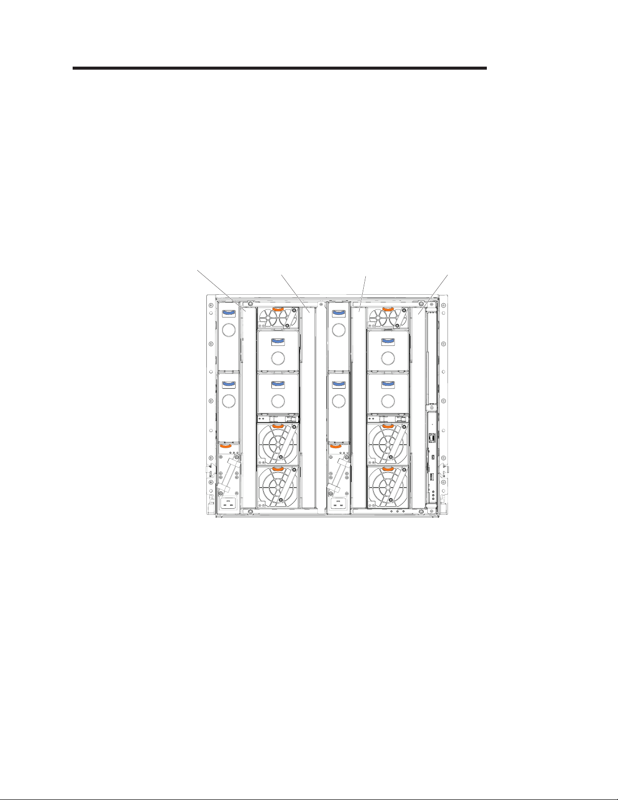
The following illustration shows an example of a IBM Flex System chassis with the
I/O bays identified.
I/O module
bay 1
I/O module
bay 3
I/O module
bay 2
I/O module
bay 4
To enable the switch to communicate with a compute node, at least one switch
must be installed in the IBM Flex System chassis. For details about network
adapter installation, configuration, and use, see the documentation that comes with
the network adapter.
Installing a second switch enables a redundant path and a separate connection
from the compute node to the external Ethernet network.
The IBM Flex System chassis supports a maximum of four switch modules.
Depending on the type of IBM Flex System chassis that you are using, the IBM
Flex System chassis supports a maximum of ten or fourteen network adapters.
Notes:
v I/O bays 1 and 2 support any standard Ethernet switch or pass-thru modules that
connects to the two integrated Ethernet controllers in each of the compute nodes.
When you install an adapter card in the first bay on the compute node, the I/O
© Copyright IBM Corp. 2013 3
Page 14
bays support any switch with the same type of network interface that is used in
the corresponding compute node adapter bay.
v The I/O bays 3 and 4 support Ethernet switch modules, Fibre Channel switch
modules, Infiniband, and pass-thru modules (optical and copper) if the serial
pass-thru modules are not being used. If you install an additional I/O module in
bay 3 or 4, a corresponding adapter card is required to be installed in each
compute node to access the I/O bay.
v The compute nodes or IBM Flex System chassis that are described or shown in
this document might be different from your compute nodes or IBM Flex System
chassis. For additional information, see the documentation that comes with your
compute node or IBM Flex System chassis.
v When the switch is installed in a IBM Flex System chassis, the internal ports
operate at 10 Gbps or 1 Gbps. The external ports can operate at 10 Gbps or 1
Gbps, depending on the SFP module type.
Before installing the switch module
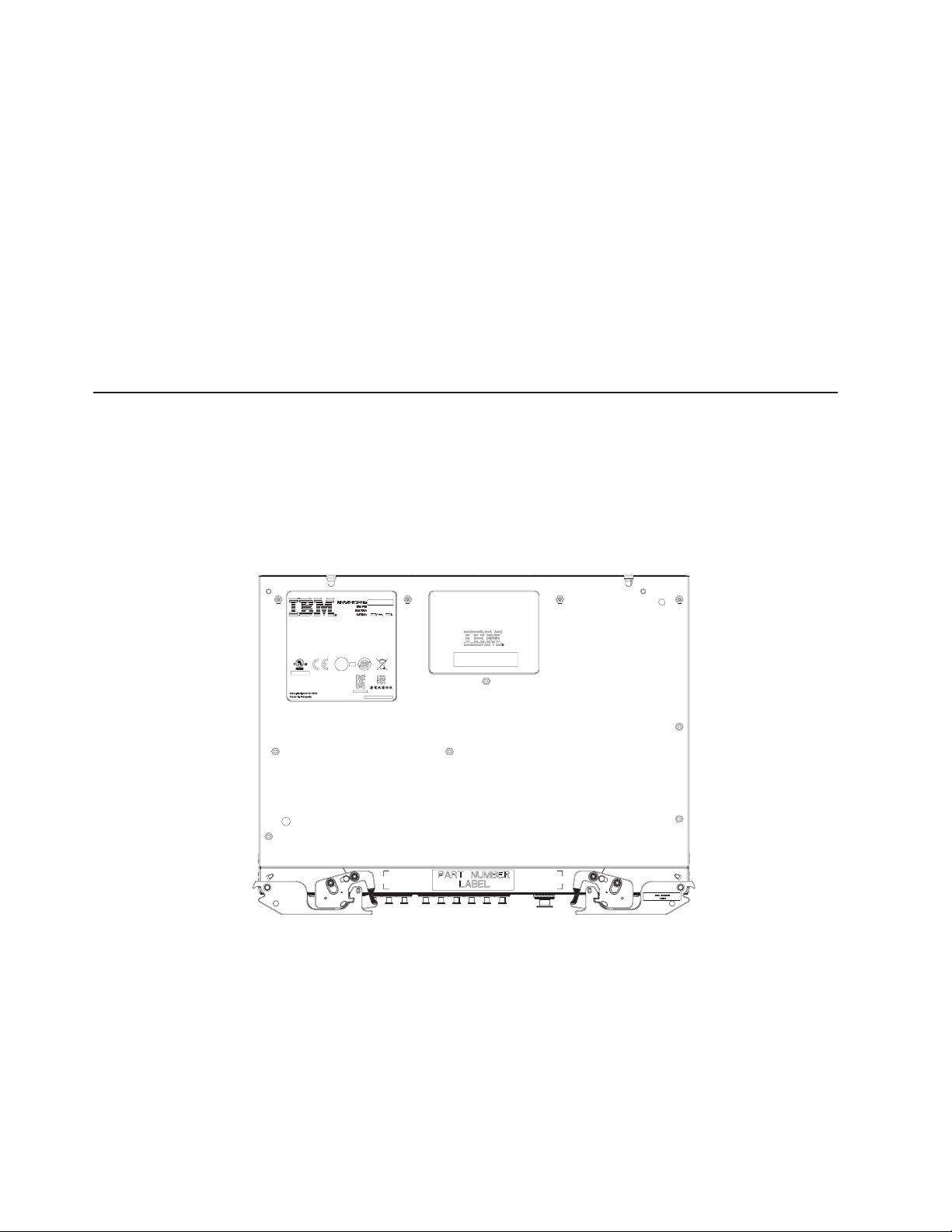
Locate and record information about the switch module in the following table. The
labels contain the product name, model number, serial number, part number and
the media access control (MAC) address for the switch module. After the switch
module is installed most of the labels are hidden from view (located on the bottom
and rear of the module) and require removing the switch module in order to relocate
them.
Figure 1. Label locations
Record this information below and print this page and keep it in a safe place for
possible future reference. You will need this information when you register the
switch module with IBM. You can register the switch at http://www.ibm.com/support/
mysupport/.
4 EN2092 1 Gb Ethernet Scalable Switch: User's Guide
Page 15

Product name IBM Flex System EN2092 1 Gb Ethernet Scalable Switch
Model number _____________________________________________
Serial number _____________________________________________
Part number _____________________________________________
Media access control
(MAC) address for switch
MAC addresses for other
components
Installation guidelines
Before you install the switch in the IBM Flex System chassis, read the following
information:
v Read the safety information that begins on page v, “Handling static-sensitive
devices” on page 6, and the safety statements in the IBM Flex System chassis
documentation. This information provides a safe working environment.
v Observe good housekeeping in the area where you are working. Place removed
covers and other parts in a safe place.
v Blue on a component indicates touch points, where you can grip the component
to remove it from or install it in the blade server or IBM Flex System chassis,
open or close a latch, and so on.
v Orange on a component or an orange label on or near a component on the
switch, blade server, or IBM Flex System chassis indicates that the component
can be hot-swapped, which means that if the IBM Flex System chassis and
operating system support hot-swap capability, you can remove or install the
component while the IBM Flex System chassis is running. (Orange can also
indicate touch points on hot-swap components.) See the instructions for removing
or installing a specific hot-swap component for any additional procedures that
you might have to perform before you remove or install the component.
v You do not have to turn off the IBM Flex System chassis to install or replace any
of the hot-swap modules on the front or rear of the IBM Flex System chassis.
v When you install a switch in the IBM Flex System chassis, you must also install a
compatible I/O expansion card in the blade server to support the switch.
v When you are finished working on the blade server or IBM Flex System chassis,
reinstall all safety shields, guards, labels, and ground wires.
v For a list of supported optional devices for the IBM Flex System chassis and
other IBM products, see http://www.ibm.com/servers/eserver/serverproven/
compat/us/.
_____________________________________________
_____________________________________________
_____________________________________________
_____________________________________________
System reliability guidelines
To help ensure proper cooling, performance, and system reliability, make sure that
the following requirements are met:
v Each of the module bays on the rear of the IBM Flex System chassis contains
either a module or a filler module.
v A removed hot-swap module is replaced with an identical module or filler module
within 1 minute of removal.
v A removed hot-swap compute node is replaced with another compute node or
filler node within 1 minute of removal.
v The ventilation areas on the sides of the compute node are not blocked.
Chapter 2. Installing and removing the switch module 5
Page 16

v You have followed the reliability guidelines in the documentation that comes with
the IBM Flex System chassis.
Cable requirements for the switch are described in the IBM Configuration and
Options Guide at http://www.ibm.com/servers/eserver/xseries/cog/. See the
documentation that comes with the IBM Flex System chassis for cable-routing
information.
Handling static-sensitive devices
Attention: Static electricity can damage the IBM Flex System chassis and other
electronic devices. To avoid damage, keep static-sensitive devices in their
static-protective packages until you are ready to install them.
To reduce the possibility of electrostatic discharge, observe the following
precautions:
v Limit your movement. Movement can cause static electricity to build up around
you.
v Handle the device carefully, holding it by its edges or its frame.
v Do not touch solder joints, pins, or exposed printed circuitry.
v Do not leave the device where others can handle and damage it.
v While the device is still in its static-protective package, touch it to an unpainted
metal surface of the IBM Flex System chassis or an unpainted metal surface on
any other grounded rack component in the rack that you are installing the device
in for at least 2 seconds. This drains static electricity from the package and from
your body.
v Remove the device from its package and install it directly into the IBM Flex
System chassis without setting down the device. If it is necessary to set down
the device, put it back into its static-protective package. Do not place the device
on the IBM Flex System chassis or on a metal surface.
v Take additional care when you handle devices during cold weather. Heating
reduces indoor humidity and increases static electricity.
v Some types of IBM Flex System chassis come with electrostatic discharge (ESD)
connectors. If your unit is equipped with an ESD connector, see the
documentation that comes with the IBM Flex System chassis for using the ESD
connector.
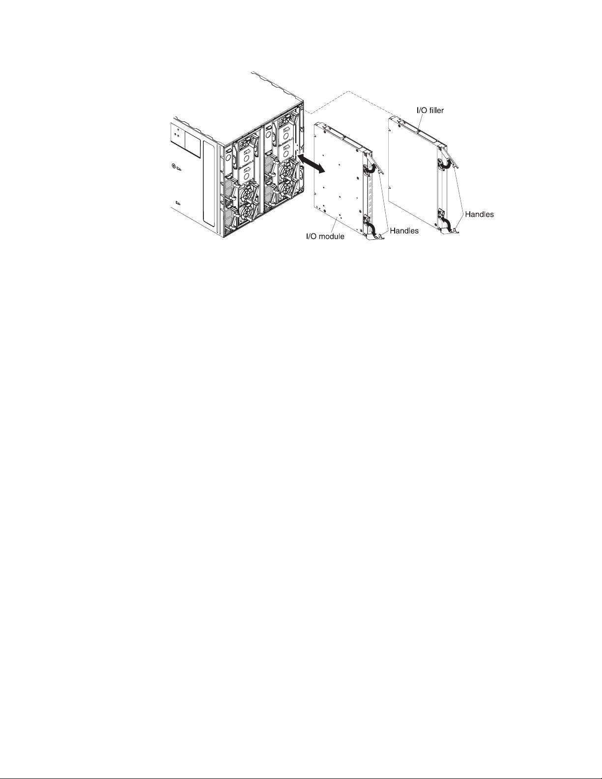
Installing the switch module
Note: The following illustration shows how to install a switch in a IBM Flex System
chassis. The appearance of your IBM Flex System chassis might be
different; see the documentation for your IBM Flex System chassis for
additional information.
Use the following instructions to install a switch in the IBM Flex System chassis.
You can install a switch while the IBM Flex System chassis is powered on. For
redundancy support, you must install I/O modules of the same type in I/O bays 1
and 2, and I/O modules of the same type in bays 3 and 4 of the chassis.
To install a switch, complete the following steps.
6 EN2092 1 Gb Ethernet Scalable Switch: User's Guide
Page 17
1. Read the safety information that begins on page v and “Installation guidelines”
on page 5.
2. Verify that the switch is compatible with the chassis. For a list of supported
optional devices for the IBM Flex System chassis and other IBM products, see
http://www.ibm.com/servers/eserver/serverproven/compat/us/.
3. Select I/O bay in which to install the switch.
Note: For details about I/O bay requirements and bay locations, see the
documentation for the IBM Flex System chassis and compute nodes.
4. Remove the filler module from the selected bay. Store the filler module for
future use.
5. If you have not already done so, touch the static-protective package that
contains the switch to an unpainted metal surface of the IBM Flex System
chassis or an unpainted metal surface on any other grounded rack-component
for at least 2 seconds.
6. If the removed filler module (from step 4) occupied two bays:
v Remove the single-high filler module from its static-protective package.
v Install the single-high filler module into the unused bay.
7. Remove the switch from its static-protective package.
8. Make sure that the release levers on the switch are in the open position
(perpendicular to the switch).
9. Slide the switch into the applicable I/O-module bay until it stops.
10. Push the release levers on the front of the switch to the closed position. After
you insert and lock the switch, it is turned on, and a power-on self-test (POST)
occurs to verify that the switch is operating correctly.
Notes:
a. The switch takes approximately 60 seconds to complete the POST. When
the switch is turned on, an LED test occurs. All LEDs are lit and remain lit
during POST; then, all the LEDs except the OK LED turn off. This indicates
normal POST results.
b. To maintain proper airflow, make sure that the ventilation holes on the front
of the switch are not blocked.
11. Make sure that the LEDs on the switch indicate that it is operating correctly
(see “Information LEDs” on page 15).
12. If you have another switch to install, repeat step 4 through step 11; otherwise,
go to the next step.
Chapter 2. Installing and removing the switch module 7
Page 18
13. Install the SFP+ modules in the switch. For information and instructions, see
“Installing and removing the 10 Gb SFP+ module” on page 11 and the
documentation that comes with the SFP+ module.
14. Attach any cables that are required by the switch. For additional information
about cabling the switch, see “Cabling the switch module and the SFP+
module” on page 9, the documentation that comes with the cables, and the
optional network devices to which the cables have been connected. For the
locations of the connectors on the IBM Flex System chassis, see the
documentation that comes with the IBM Flex System chassis. Then, continue
with the next step.
15. Make sure that the external ports on the switch are enabled through one of the
management-module interfaces, such as the Web-based interface or the CLI.
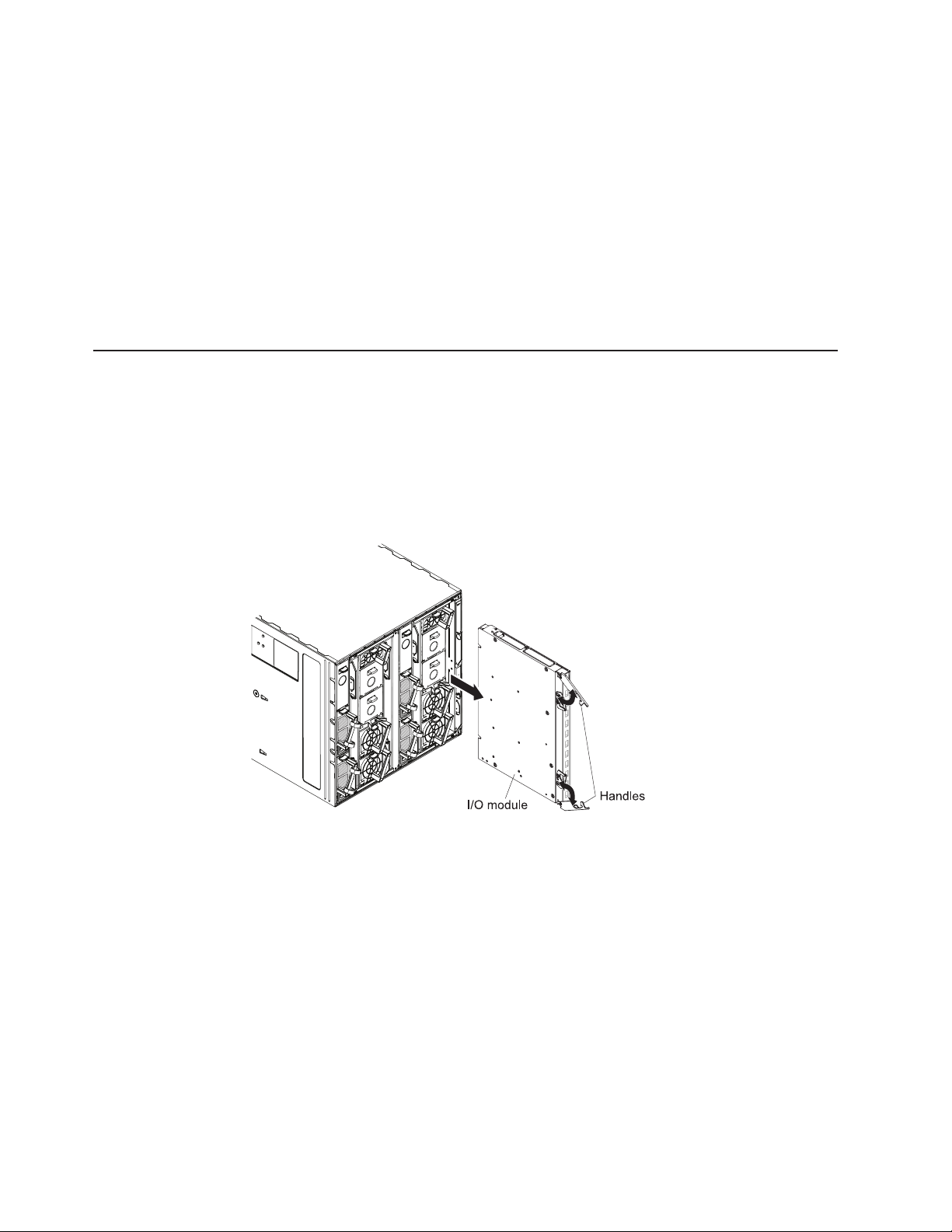
Removing and replacing the switch module
Note: The following illustration shows how to remove and replace a switch from a
IBM Flex System chassis. The appearance of your IBM Flex System chassis
might be different; see the documentation for your IBM Flex System chassis
for additional information.
To replace a switch, complete the following steps.
1. Read the safety information that begins on page v, and “Installation guidelines”
on page 5.
2. Disconnect any cables from the switch that you are removing. Removing these
cables (especially an Ethernet cable) disrupts the network connection from the
external Ethernet port to any connected external Ethernet devices. If you plan to
replace the switch with another switch, you can use the existing Ethernet cable,
provided that it remains securely attached to the Ethernet network. For
additional information about cabling the switch, see “Cabling the switch module
and the SFP+ module” on page 9, the documentation that comes with the
cables, and the optional network devices to which the cables have been
connected. For the locations of the connectors on the IBM Flex System chassis,
see the documentation that comes with the IBM Flex System chassis. Then,
continue with step 3.
3. Pull the release latches out from the switch. The switch moves out of the bay
approximately 0.6 cm (0.25 inch).
4. Slide the switch out of the bay and set it aside.
8 EN2092 1 Gb Ethernet Scalable Switch: User's Guide
Page 19

5. Place either another switch or a filler module in the bay.
Important: Complete this step within 1 minute. (For more information, see steps
10 and 11 on page 7.)
6. If you placed a filler module in the bay, continue with “Installing and removing
the 10 Gb SFP+ module” on page 11.
7. If you placed a switch in the bay, reconnect the other cables that you
disconnected. Attach any additional cables that are required by the switch. For
additional information about cabling the switch, see “Cabling the switch module
and the SFP+ module,” the documentation that comes with the cables, and the
optional network devices to which the cables have been connected. For the
locations of the connectors on the IBM Flex System chassis, see the
documentation that comes with the IBM Flex System chassis. Then, continue
with “Installing and removing the 10 Gb SFP+ module” on page 11.
Cabling the switch module and the SFP+ module
This section describes cable connections for the switch module. For more
information about these component part numbers, see Chapter 6, “Parts listing,” on
page 29.
Note: The illustrations in this document might differ slightly from your hardware.
Connecting the serial console cable
To connect the serial console cable to the switch module, connect the serial cable
to the mini-USB serial console port of the switch module and the other end of the
cable to the console device.
Disconnecting the serial console cable
To disconnect the serial console cable, grasp the connector and gently pull the
cable from the switch module.
Connecting the SFP+ module cable
Attention: To avoid damage to the fiber optic cables, follow these guidelines:
v Do not route the cable along a folding cable-management arm.
v When you attach the cable to a device on slide rails, leave enough slack in the
cable so that it does not bend to a radius of less than 38 mm (1.5 in.) when the
device is extended or become pinched when the device is retracted.
v Route the cable away from places where it can be snagged by other devices in
the rack.
v Do not overtighten the cable straps or bend the cables to a radius of less than 38
mm (1.5 in.).
v Do not put excess weight on the cable at the connection point. Make sure that
the cable is well supported.
To connect the SFP+ module cable, complete the following steps.
1. Remove the protective caps from the end of the fiber optic cable.
Chapter 2. Installing and removing the switch module 9
Page 20

Fiber-optic
cable
Protective cap
2. Gently slide the fiber optic cable into the SFP+ module until it clicks into place.
3. Check the LEDs on the switch. When the switch is operating correctly, the
green link LED is lit. For information about the status of the switch LEDs, see
“Locating the information panels, LEDs, and external ports” on page 13.
Disconnecting the SFP+ module cable
To disconnect the SFP+ module cable, complete the following steps.
1. Squeeze the release tabs and gently pull the fiber optic cable from the SFP+
module.
2. Replace the protective caps on the ends of the fiber optic cable.
Connecting the RJ-45 cable
To connect the RJ-45 connector to the switch, push the RJ-45 cable connector into
the port connector until it clicks into place.
Disconnecting the RJ-45 cable
To disconnect the RJ-45 connector, squeeze the release tab and gently pull the
cable connector out of the switch-module connector.
10 EN2092 1 Gb Ethernet Scalable Switch: User's Guide
Page 21

Installing and removing the 10 Gb SFP+ module
The switch supports the 10 Gb small-form-factor pluggable (SFP+) module and the
1 Gb small-form-factor pluggable (SFP) module. The SFP+ and SFP modules are
laser products that convert electrical signals to optical signals.
For additional information about the location of the switch, the network interface
requirements, and expansion options, see the documentation for your IBM Flex
System chassis.
Notes:
1. The illustrations in this document might differ slightly from your hardware.
2. While the information in this section describes the 10 Gb small-form-factor
pluggable (SFP+) module, it also applies to the 1 Gb small-form-factor
pluggable (SFP) module.
3. The switch also supports MSA-compliant copper direct-attach cables (DAC), up
to 7 m (23 ft) in length.
Handling the SFP+ module
Before you install an SFP+ module, read the following information:
v The module housing of the SFP+ has an integral guide key that is designed to
prevent you from inserting the module incorrectly.
v Use minimal pressure when you insert the module into the port. Forcing the
module into the port can cause damage to the module or the module port.
v You can insert or remove the module while the IBM Flex System chassis is
turned on.
v You must first insert the module into the port before you can connect the cables.
v You must remove the cable from the SFP+ module before you remove the SFP+
module from the switch.
Statement 3:
CAUTION:
When laser products (such as CD-ROMs, DVD drives, fiber optic devices, or
transmitters) are installed, note the following:
– Do not remove the covers. Removing the covers of the laser product
could result in exposure to hazardous laser radiation. There are no
serviceable parts inside the device.
– Use of controls or adjustments or performance of procedures other than
those specified herein might result in hazardous radiation exposure.
Chapter 2. Installing and removing the switch module 11
Page 22

DANGER
Some laser products contain an embedded Class 3A or Class 3B laser
diode. Note the following.
Laser radiation when open. Do not stare into the beam, do not view
directly with optical instruments, and avoid direct exposure to the beam.
Class 1 Laser Product
Laser Klasse 1
Laser Klass 1
Luokan 1 Laserlaite
Appareil A Laser de Classe 1
`
Installing the SFP+ module
The SFP+ module provides two fiber-optic cable connectors for connecting to
external ports. To install the SFP+ module, complete the following steps.
1. Read the safety information that begins on page v and “Installation guidelines”
on page 5.
2. If you have not already done so, touch the static-protective package that
contains the SFP+ module to an unpainted metal surface of the IBM Flex
System chassis or an unpainted metal surface on any other grounded rack
component in the rack in which you are installing the switch for at least 2
seconds.
3. Read the information in “Handling the SFP+ module” on page 11.
4. Remove the SFP+ module from its static-protective package.
5. Remove the protective cap, if one is installed, from the SFP+ module port
where you are installing the SFP+ module and store it in a safe place.
6. Remove the protective cap from the SFP+ module and store it in a safe place.
Attention: To avoid damage to the cable or the SFP+ module, make sure that
you do not connect the fiber optic cable before you install the SFP+ module.
7. Insert the SFP+ module into the SFP+ module port until it clicks into place.
8. Connect the fiber optic cable (see “Connecting the SFP+ module cable” on
page 9) and any cables that you disconnected earlier.
12 EN2092 1 Gb Ethernet Scalable Switch: User's Guide
Page 23

Removing the SFP+ module
To remove the SFP+ module, complete the following steps.
1. Read the safety information that begins on page v and “Installation guidelines”
on page 5.
2. Read the information in “Handling the SFP+ module” on page 11.
3. Remove the fiber optic cable from the SFP+ module that you want to replace.
For more information about removing the cable, see “Disconnecting the SFP+
module cable” on page 10.
Attention: To avoid damage to the cable or the SFP+ module, make sure that
you disconnect the fiber-optic cable before you remove the SFP+ module.
4. Unlock the SFP+ module by pulling the wire tab straight out, as shown in the
following illustration.
5. Grasp the wire tab on the SFP+ module and pull it out of the port.
6. Replace the protective cap on the SFP+ module and the SFP+ module port.
7. Place the SFP+ module into a static-protective package.
Locating the information panels, LEDs, and external ports
This section describes the information panels and LEDs on the switch and identifies
the external ports on the information panels.
Note: The illustrations in this document might differ slightly from your hardware.
Information panel
The front panel of the switch contains information LEDs, four SFP+ module port
connectors, one mini-USB serial port connector, and twenty RJ-45 ports.
Chapter 2. Installing and removing the switch module 13
Page 24

The switch-module information panel contains the following components:
v LEDs that display the following information:
– The status of the switch and its network connection
– The status of the external connections to the switch
For further details about LEDs, see “Information LEDs” on page 15.
14 EN2092 1 Gb Ethernet Scalable Switch: User's Guide
Page 25

v Four SFP+ port connectors to attach SFP+ modules and twenty RJ-45 ports.
v One mini-USB serial port connector for console port use (management purposes)
Information LEDs
The front panel of the switch has two sets of LEDs. The OK and switch error LEDs
in the first column at the bottom of the switch indicate the switch status. The link
(LINK) and activity (TX/RX) LEDs indicate the status of the external ports. .
Notes:
v A yellow LED on the IBM Flex System chassis is lit when a system error or event
v An LED test occurs whenever the switch is turned on. All LEDs are lit and remain
Any errors that are detected during POST are written to the system log. For
information about the command to read the system log, see the IBM Command
Reference for the switch.
When POST errors are written to the system log, these errors are also written to
the IBM Flex System management-module event log. If a hardware error, such as a
current fault occurs, the management module displays it. If a firmware error occurs,
the management module displays the Module did not complete POST message and
a post error code that indicates the test that was running when the error was
detected.
only. Do not attach any devices to this connector other than the serial cable that
comes with the switch, as described in “Cabling the switch module and the SFP+
module” on page 9.
has occurred. To identify the error or event, check the IBM Flex System
management-module event log or the switch system log.
lit during POST, and then all the LEDs except the OK LED turn off.
Note: You can also use the management module to make sure that the switch is
operating correctly. For more information, see the documentation for the IBM
Flex System chassis.
Switch status LEDs
The following table provides descriptions of the switch status LEDs on the front
panel of the switch.
Table 1. Switch status LEDs
Status LED Description
OK (
Switch error (!) LED This yellow LED is at the bottom of the switch on the front panel.
) LED
This green LED is at the bottom of the switch on the front panel.
v When this LED is lit, it indicates that the switch is on.
v When this LED is not lit and the yellow switch error LED is lit, it
indicates a critical alert. If the yellow LED is also not lit, it indicates
that the switch is off.
v When this LED is lit, it indicates a POST failure or critical alert.
Note: When this LED is lit, the system-error LED on the IBM Flex
System chassis is also lit.
v When this LED is not lit and the green LED is lit, it indicates that
the switch is working correctly. If the green LED is also not lit, it
indicates that the switch is off.
Chapter 2. Installing and removing the switch module 15
Page 26

Port status LEDs
The following table provides descriptions of the port status LEDs on the front panel
of the switch.
Table 2. Port status LEDs
Status LED Description
Link LED This green LED indicates whether the port link is up or down.
v When this LED is lit, there is an active connection (or link)
between the corresponding port and the device that is using this
connection.
v When this LED is not lit, it indicates that there is no signal on the
corresponding port, or the link is down.
Activity (TX/RX) LED This yellow LED indicates the status of the link activity for the port.
v When this LED is flashing or lit, the corresponding port is
connected and online, and link activity is occurring on that port.
v When this LED is not lit, it indicates that there is no signal or no
link activity on the corresponding port.
16 EN2092 1 Gb Ethernet Scalable Switch: User's Guide
Page 27

Chapter 3. Configuring the switch
The switch module has an internal Ethernet path to the management module,
twenty-four external Ethernet ports, and a serial console port. The switch supports
two remote-access modes for management through Ethernet connections. You can
select the mode that is best suited for your IBM Flex System environment.
v Default mode: The default mode uses the internal path to the management
module only. In this mode, the remote-access link to the management console
must be attached to the Ethernet connector on the management module. The
Internet protocol (IP) addresses and SNMP parameters of the switches can be
automatically assigned by the IBM Director Flex System Deployment wizard
(when available), or you must assign them through the IBM Flex System
Management and Configuration program. This mode provides a secure LAN for
management of the IBM Flex Systems subsystems that is separate from the data
network. See “Establishing a TCP/IP session through the management module”
on page 18 for more information.
v Remote management mode: You can enable remote management of the switch
through the external ports, instead of or in addition to access through the
management module. This mode can be enabled only through the
management-module configuration interface. When this mode is enabled, the
twenty external RJ-45 ports and the four external SFP+ ports support both
management traffic and IBM Flex System application data traffic.
This mode enables the use of additional switch IP addresses on different IP
subnets than the management modules. This is useful when the switches are to
be managed and controlled as part of the overall network infrastructure, while
secure management of other IBM Flex System subsystems is maintained through
the management module. See “Enabling management through external ports” on
page 19 for additional instructions about configuring the switch for this mode of
operation.
The mini-USB console port provides an alternative path to manage and configure
the switch for local access.
Important:
v Before you configure the switch, make sure that the management modules in the
IBM Flex System chassis are correctly configured. For more information about
configuring the switch, see the following documents:
– IBM Flex System Chassis Management Module Installation Guide
– IBM Flex System Chassis Management Module User’s Guide
v The default IP address of the switch is 192.168.70.120, 192.168.70.121,
192.168.70.122, or 192.168.70.123, depending on the switch bay where it is
installed.
v If you change the IP address of the switch and restart the IBM Flex System
chassis, the switch maintains this new IP address as its default value.
v When configuring the switch using the management interfaces, note that the
apply command changes the currently active configuration. If you want the
configuration change to persist beyond the next reboot of the switch, you must
run the copy running-config startup-config command. This command stores
the current switch configuration and all changes in NVRAM.
If the switch restarts and the management module cannot apply the saved
configuration, the switch defaults to the configuration that was previously saved.
If the IP subnet address of the switch does not match the IP subnet address of
© Copyright IBM Corp. 2013 17
Page 28

the management module, you can no longer manage the switch from the
management module. For more information about configuring the switch, see the
Command Reference for the switch.
v When you use the management-module Web interface to update the switch
configuration, the management-module firmware saves the new configuration in
internal nonvolatile random-access memory (NVRAM). If the switch restarts, the
management module applies the saved configuration to the switch. For more
information, see the Application guide and Command Reference.
v For switch communication with a remote management station, such as an IBM
Director management server, through the management-module external Ethernet
port, the switch internal-network interface and the management-module external
interface must be on the same IP subnet.
For specific details about configuring the switch and preparing for system
installation, see the documentation listed in “Related documentation” on page 1.
Notes:
v Unless otherwise stated, references to the management module apply only to the
IBM Flex System Advanced Management Module, which is the only type of
management module that supports the switch.
v Throughout this document, the user name is also known as the login name or
user ID for logging on to interfaces or programs.
v The screens that are described or referenced in this document might differ
slightly from the screens that are displayed by your system. Screen content
varies according to the type of IBM Flex System chassis and the firmware
versions and options that are installed.
Establishing a TCP/IP session through the management module
To establish a TCP/IP session for the switch through the IBM Flex System Chassis
Management Module (CMM), complete the following steps.
1. Log on to the IBM Flex System Chassis Management Module (CMM) CLI as
described in the User’s Guide or Command Line Interface Reference Guide for
the CMM. If necessary, obtain the IP address of the management module from
your system administrator.
Note: The User ID and Password fields are case-sensitive. Type your
information in uppercase letters only. To maintain system security,
change your password after you log on for the first time. The default
User ID is USERID, and the default password is PASSW0RD (where the sixth
character is the number zero, not the letter O).
2. From the I/O Module Tasks menu, click Configuration.
3. In the I/O Module Configuration area, click the bay number that corresponds
to the location of the switch that you installed.
4. In the IP address field in the New Static IP Configuration area, type the new
TCP/IP address of the switch; then, click Save.
Note: The management module does not check for invalid IP addresses.
5. Click Advanced Configuration. You can now start a Web session or a Telnet
session.
The Web interface application and the Telnet interface provide different ways to
access the same internal-switching firmware and configure it.
18 EN2092 1 Gb Ethernet Scalable Switch: User's Guide
Page 29

v If your system application requires that you use the Web interface application,
see “Configuring the switch through the switch browser-based interface” on page
21 for additional information.
v If your system application requires that you use the SSHv2/Telnet client software,
see “Configuring the switch through the SSHv2/Telnet interface” for additional
information.
Enabling management through external ports
To access and manage the switch through external interfaces, you must enable the
external ports and the ability to manage the switch through them. Use the
information in the following table to configure your ports.
External management External ports Description
Disabled Disabled The switch must be managed
Disabled Enabled The switch must be managed
Enabled Disabled The switch can be managed
Enabled Enabled The switch can be managed
through the management
module. No traffic is allowed on
external ports.
through the management
module. Data traffic is allowed
on external ports.
through the management
module or a blade server. No
traffic is allowed on external
ports.
through the management
module, a blade server, or a
management station that is
connected through an external
port. Data traffic is allowed on
external ports.
To enable management through external ports, complete the following steps.
1. Log on to the IBM Flex System Chassis Management Module (CMM) CLI as
described in the User’s Guide or Command Line Interface Reference Guide for
the CMM. If necessary, obtain the IP address of the management module from
your system administrator.
2. Click I/O Module Tasks > Configuration and click the bay number that
corresponds to the location of the switch that you installed.
3. Click Advanced Configuration and make sure that external management is
enabled.
4. Click I/O Module Tasks > Admin/Power/Restart and make sure that the
external ports are enabled for the switch that you installed.
Configuring the switch through the SSHv2/Telnet interface
Note: Telnet is disabled by default.
Chapter 3. Configuring the switch 19
Page 30

The switch supports a command-line interface (CLI) that you can use to configure
and control the switch over the network through the SSHv2/Telnet program. You can
use the CLI to perform many basic network-management functions. In addition, you
can configure the switch for management through an SNMP-based
network-management system. The following sections describe how to use the Telnet
interface to access the switch, change its settings, and monitor its operation.
Connecting to the switch
If you know the IP address for the switch and you have an existing network
connection, you can use the SSHv2/Telnet interface from an external management
station or the management module to access and control the switch. The
management station and the switch must be on the same IP subnet. If you have to
obtain the IP address for the switch or establish a network connection, contact your
system or network administrator. Be sure to use the correct IP address in the
required command, as specified in “Accessing the main menu.”
Accessing the main menu
To connect to the switch through the SSHv2/Telnet interface, complete the following
steps.
1. From a DOS command-line prompt, type telnet x and press Enter.
where x is the IP address for the switch.
2. If you do not have an assigned initial password, in the Password field, type the
default password (where the sixth character is the number zero, not the letter O)
and press Enter.
Important: The apply command changes the currently active configuration. If you
want your change to persist beyond the next reboot of the switch, you must enter
the save command. This command stores the current switch configuration and all
changes in nonvolatile memory.
For more information about configuring through the CLI, see the Application Guide
for the switch.
Configuring the switch through the serial-port interface
The mini-USB serial port provides basic communication through a terminal
emulation program (such as Hyperterminal). Because messages from the power-on
self-test (POST) and all initialization information are transmitted through the serial
port, you can use the serial port to log in to the switch and access and configure
the internal switching firmware.
To log in to the switch, complete the following steps.
1. Connect one end of the specifically designed serial cable that comes with your
device into the mini-USB port and connect the other end to the management
station.
20 EN2092 1 Gb Ethernet Scalable Switch: User's Guide
Page 31

For additional information, see “Connecting the serial console cable” on page 9.
2. On the management station, open a console window and make sure that the
serial port is configured with the following settings:
v 9600 baud
v 8 data bits
v No parity
v 1 stop bit
v No flow control
3. Type the user name and password. The default user name is USERID. The
default password is PASSW0RD (where the sixth character is the number zero, not
the letter O).
The serial port is compatible with the standard 16550 Universal Asynchronous
Receiver/Transmitter (UART) protocol. The mini-USB serial port is enabled by
default.
Configuring the switch through the switch browser-based interface
Note: HTTP is disabled by default. HTTPS is not disabled by default.
Before you can access and start the browser-based interface, make sure that you
have completed the following procedures:
v Install the switch in the IBM Flex System chassis.
v Make sure that the switch firmware is installed on the switch.
v Configure at least one IP interface on the switch.
v Enable frames and the JavaScript program in your Web browser.
The following hardware and software are required for the Web interface:
v A frame-capable Web-browser program, such as Internet Explorer (version 7.0 or
later), Mozilla Firefox (version 8.0 or later), or Google Chrome (version 16.0 or
later)
v A computer or workstation with network access to the switch
To start the browser-based interface, complete the following steps.
1. Start a Web browser. The Web-browser window opens.
2. In the URL field, enter the IP address of the switch, in the following format:
http://xxx.xxx.xxx.xxx. The login window opens.
3. Type the switch user ID and password and click OK. The default user ID is
USERID. The default password is PASSW0RD (where the sixth character is the
number zero, not the letter O).
Chapter 3. Configuring the switch 21
Page 32

Note: The passwords that are used to access the switch are case-sensitive. To
increase system security, change the password after you log on for the first
time.
Initial configuration
The operating firmware on the switch contains default configuration files that are
installed during the firmware installation. These initial configuration settings are not
in a separate configuration file but are components of the firmware. When you
restore the management module to factory defaults, the original configuration is
restored. For more information about configuring and managing the switch through
the management module, see the Command Reference for the switch.
Logging in to the switch
The switch supports user-based security that enables you to prevent unauthorized
users from accessing the switch or changing its settings.
To log in to the switch, complete the following steps.
1. At the prompt, type your user ID and press Enter. The default user ID is USERID.
2. Type your password and press Enter. The default password is PASSW0RD (where
the sixth character is the number zero, not the letter O). The main-menu window
opens.
After you log on to the switch, you must set the date and time. See the Command
Reference for the switch to perform this task and others as needed.
22 EN2092 1 Gb Ethernet Scalable Switch: User's Guide
Page 33

Chapter 4. Updating the firmware and licensing
This chapter describes how to determine the level of the firmware that is installed
on the switch, how to obtain the latest level of switch firmware, how to upgrade the
firmware, how to acquire additional feature licensing, and how to reset the switch to
activate the firmware upgrade.
Note: Configuration settings can be lost during a firmware update. Before updating
the firmware, save a copy of the configuration on a separate device. In the
event of a failed update, the saved configuration can be restored. For more
information about the configuration file, see the Application guide and
Command Reference for the switch.
Determining the level of switch firmware
After you install the switch in the IBM Flex System chassis, make sure that the
latest firmware is installed on the switch. To determine the level of the firmware that
is installed, complete the following steps.
1. Log on to the management module CLI as described in the switch's User's
Guide or CLI Reference Guide. If necessary, obtain the IP address of the
management module from your system administrator.
2. Set the environment to the bay where you installed the switch. For example:
system> env -T system:switch[1]
3. Type the info command to display switch firmware information:
system:switch[1]> info
...
Boot ROM
Main application
Main application
Rel date: 04/02/2013
Version: 7.7.1.12
Status: Active
Rel date: 04/02/2013
Version: 7.7.1.12
Status: Active
Rel date: 03/22/2013
Version: 7.7.1.12
Status: Inactive
Obtaining the latest level of switch firmware
The latest firmware update for the switch module is available at
http://www.ibm.com/support/fixcentral.
Note: Changes are made periodically to the IBM Web site. The procedure for
locating firmware and documentation might change from what is described in
this document.
© Copyright IBM Corp. 2013 23
Page 34

Upgrading the switch firmware
You can upgrade the switch firmware by using a server application. Typically, this
firmware runs as an application under your operating system. Make sure that this
firmware is installed on your file server; then, download the firmware images from
http://www.ibm.com/systems/support/ into a directory on your server. Enable the file
and set the default directory to the directory where the image resides.
Note: If you want your change to persist beyond the next reboot of the switch, you
must type the copy running-config startup-config command. This
command stores the current switch configuration and all changes in
nonvolatile memory.
To transfer the firmware image files from the file server to the switch, you can
establish a SSHv2/Telnet session through the management module. Ping the file
server to make sure that you have a connection. The session performs optimally if
all three network entities (file server, management module, and switch IP
addresses) are on the same subnet. Otherwise, you must use a router and
configure a gateway address on the switch. Use the management-module interface
to configure the IP addresses of the management module external interface (eth0)
and the switch so that they are both on the same subnet as the file server.
Examples of IP addresses and masks are described in the following table.
Network entity IP address Mask
TFTP server 192.168.2.178 255.255.255.0
Management module (eth0) 192.168.2.237 255.255.255.0
Switch-module current IP
configuration (IF 128)
192.168.2.51 255.255.255.0
Note: With this configuration, you can ping the switch from the TFTP server.
Access the switch command line interface (CLI). Refer to the Command Reference
for more information.
To upgrade the switch firmware, complete the following steps.
1. Log in to the switch.
2. At the CLI prompt, type the following command and press Enter.
/boot/gtimg imageX TADDR zzzzz
Where imagex is the image to install, TADDR is the address of TFTP server, and
zzzzz is the operating-system image file name.
3. At the CLI prompt, type the following command and press Enter.
/boot/gtimg boot TADDR yyyy
Where yyyy is the boot image file name.
4. Press Enter for user name.
5. Enter data path (either mgt or data).
6. Reset and restart the switch as described in “Resetting and restarting the
switch” on page 25.
24 EN2092 1 Gb Ethernet Scalable Switch: User's Guide
Page 35

Resetting and restarting the switch
To activate the new image or images, you must reset the switch. To reset the
switch, complete the following steps.
1. Log on to the management module CLI as described in the switch CLI
Reference Guide . If necessary, obtain the IP address of the management
module from your system administrator.
2. Set the environment to the bay where you installed the switch. For example:
system> env -T system:switch[1]
3. Type the reset command to restart the switch. Wait approximately 100 seconds
for POST to complete.
system:mm[1]> env -T system:switch[1]
system:switch[1]> reset
4. Type the info command for the switch that was just restarted and note the
corresponding level of the firmware for the switch. Confirm that the firmware
build number reflects the correct firmware release:
system:switch[1]> info
...
Boot ROM
Main application
Main application
Rel date: 04/18/2013
Version: 7.7.1.12
Status: Active
Rel date: 04/18/2013
Version: 7.7.1.12
Status: Active
Rel date: 04/21/2013
Version: 7.7.1.12
Status: Inactive
Acquiring feature licenses
Licenses are available that enable the use of additional ports on the switch:
v Base product: twenty-four 1 Gb full duplex throughput arranged as fourteen 1 Gb
ports down and ten (RJ-45) 1 Gb ports up.
v Upgrade 1: adds fourty-eight 1 Gb full duplex throughput arranged as
twenty-eight 1 Gb ports down and twenty (RJ-45), 1 Gb ports up.
v Upgrade 2: adds eighty-eight 1 Gb full duplex throughput arranged as
twenty-eight 1 Gb ports down and twenty (RJ-45) 1 Gb ports up, and four 1 Gb
or 10 Gb SFP+ uplink ports up.
Upgrade licenses are unique to each switch and are non transferable.
To acquire an upgrade license activation key, purchase the Authorization Code and
locate the unique ID (UID) on the switch module serial number (SN) label (bottom
or rear of switch module). The UID is the last twelve characters of the switch serial
number. The serial number is located on the part number (PN) label (bottom or rear
of unit) and is also displayed during a login to any of the user interfaces. For
example: SN (UID): Y250CM294998. For more information about locating the switch
identification labels, see Before installing the switch module.
Chapter 4. Updating the firmware and licensing 25
Page 36

In the event of a switch replacement, new activation key files based on the serial
number of the replacement unit must be acquired and installed. If the replacement
is handled through IBM Service and Support, the original Authorization Code is
transferred to the serial number of the replacement unit.
The upgrade licenses can be acquired using the IBM System x Features on
Demand website http://www.ibm.com/systems/x/fod/.
You can use the website to perform the following tasks:
v Request a new activation key
v Check an authorization code to see what feature it enables and how many
remaining times it can be used to create a key
v Retrieve the history of feature activation on a selected device
v Retrieve the history of feature activation on a selected authorization code
v Retrieve a lost authorization code
v Manage your IBM customer number
v Find help for the Features on Demand feature activation process
v Provide feedback to IBM about the Features on Demand process
Note: Your IBM ID and password are required to log into the Features on Demand
web site. If you are not registered with IBM, go to http://www.ibm.com/
systems/x/fod/ and click My IBM registration in the left navigation pane.
Installing feature licenses
Once Features on Demand (FoD) activation key files have been acquired, they
must be installed on the switch. The example below illustrates use of the switch
Command Line Interface (CLI), but other interfaces may also be used (such as BBI
or SNMP). For more information about using SNMP, see the Application and ISCLI
guide(s) for the switch module. When installing licenses, please note the following
requirements:
v A switch reboot is required to fully activate the license(s).
v Both license key files can be downloaded prior to the switch reset.
v Save the configuration before upgrading the feature licenses.
Complete the following steps to install feature licenses:
1. Log in to the switch.
2. At the CLI prompt, type the following command.
/oper/swkey/enakey
3. Follow the prompts to enter values including the TFTP/SFTP server IP address
and key file name.
4. Once the key file download is complete, reset the switch to activate the
license(s).
26 EN2092 1 Gb Ethernet Scalable Switch: User's Guide
Page 37

Chapter 5. Solving problems
This section provides basic troubleshooting information to help you solve some
problems that might occur while you are setting up the switch. The Application
Guide for the switch provides more details about troubleshooting the switch.
If you cannot locate and correct a problem by using the information in this section,
see Appendix A, “Getting help and technical assistance,” on page 31.
Running POST
To ensure that it is fully operational, the switch processes a series of tests during
power-up or a restart (power-on self-test, or POST). These tests take approximately
1 minute to complete. The management module reads the test results and displays
them for you. During normal operation, these tests are completed without error, and
the green OK LED is lit. However, if the switch fails POST, the yellow switch error
LED and the system-error LED on the IBM Flex System chassis are lit. An event is
stored in the event log in the system status panel of the management module. The
specific failure is displayed on the system status I/O module panel of the
management module.
Note: For the locations and descriptions of the switch LEDs, see “Locating the
information panels, LEDs, and external ports” on page 13.
POST errors
There are two types of errors: noncritical and critical. A noncritical error applies to
one port, and the switch is operational. You can continue to operate the switch;
however, you must replace it as soon as possible. When critical errors occur, the
switch does not operate. To view POST results, complete the following steps.
1. Log on to the management module as described in the IBM Flex System
Chassis Management Module Command-Line Interface Reference Guide.If
necessary, obtain the IP address of the management module from your system
administrator. The login window opens.
2. Turn off the power to the switch; then, turn it on again.
3. After POST is completed, the management module displays the results. Refresh
the window to view the POST results. If a critical error occurs, replace the
switch. If a noncritical error occurs, see the switch error log for additional
details.
The following table describes the basic critical and noncritical failures. This
abbreviated list is representative; it is not an exhaustive list. An error code is
associated with each failure. Error codes are displayed on the Management Module
Switch Information window. Be sure to note the applicable error code and
corresponding failure. You might have to provide this information when you call for
service. For details, see Appendix A, “Getting help and technical assistance,” on
page 31.
Diagnostic indicator (in
hex)
00 - 7F Base internal functions Critical
80 - 9F Internal interface failures Noncritical
A0 - AF External interface errors Noncritical
Failing functional area Failure criticality
© Copyright IBM Corp. 2013 27
Page 38

Diagnostic indicator (in
hex)
B0 - FE Reserved Noncritical
FF Switch “good” indicator Operation
Failing functional area Failure criticality
28 EN2092 1 Gb Ethernet Scalable Switch: User's Guide
Page 39

Chapter 6. Parts listing
Replaceable components are of three types:
v Tier 1 customer replaceable unit (CRU): Replacement of Tier 1 CRUs is your
responsibility. If IBM installs a Tier 1 CRU at your request, you will be charged for
the installation.
v Tier 2 customer replaceable unit (CRU): You may install a Tier 2 CRU yourself
or request IBM to install it, at no additional charge, under the type of warranty
service that is designated for your server.
v Field replaceable unit (FRU): FRUs must be installed only by trained service
technicians.
For information about the terms of the warranty, see the Warranty Information
document.
Description CRU number (Tier 1)
IBM Flex System EN2092 1 Gb Ethernet Scalable Switch 49Y4296
IBM Flex System EN2092 1 Gb Ethernet Scalable Switch,
Upgrade 1
IBM Flex System EN2092 1 Gb Ethernet Scalable Switch,
Upgrade 2
Transceivers
10GBase-SR SFP+ (MMFiber) transceiver 44W4408
10GBase-SR SFP+ (MMFiber) transceiver 46C3447
IBM SFP+ LR transceiver 90Y9412
1000Base-SX SFP (MMFiber) transceiver 81Y1622
1000Base-T SFP transceiver 81Y1618
1000Base-LX SFP LX transceiver 90Y9424
Cables
1 m IBM passive DAC SFP+ 90Y9427
3 m IBM passive DAC SFP+ 90Y9430
5 m IBM passive DAC SFP+ 90Y9433
Serial access 90Y9338
90Y3562
49Y4298
© Copyright IBM Corp. 2013 29
Page 40

30 EN2092 1 Gb Ethernet Scalable Switch: User's Guide
Page 41

Appendix A. Getting help and technical assistance
If you need help, service, or technical assistance or just want more information
about IBM products, you will find a wide variety of sources available from IBM to
assist you. Use this information to obtain additional information about IBM and IBM
products, determine what to do if you experience a problem with your IBM system
or optional device, and determine whom to call for service, if it is necessary.
Before you call
Before you call, make sure that you have taken these steps to try to solve the
problem yourself:
v Check all cables to make sure that they are connected.
v Check the power switches to make sure that the system and any optional
devices are turned on.
v Check for updated firmware and operating-system device drivers for your IBM
product. The IBM Warranty terms and conditions state that you, the owner of the
IBM product, are responsible for maintaining and updating all software and
firmware for the product (unless it is covered by an additional maintenance
contract). Your IBM service technician will request that you upgrade your
software and firmware if the problem has a documented solution within a
software upgrade.
v If you have installed new hardware or software in your environment, check
http://www.ibm.com/systems/info/x86servers/serverproven/compat/us/ to make
sure that the hardware and software is supported by your IBM product.
v Go to http://www.ibm.com/supportportal/ to check for information to help you
solve the problem.
v Gather the following information to provide to IBM Support. This data will help
IBM Support quickly provide a solution to your problem and ensure that you
receive the level of service for which you might have contracted.
– Hardware and Software Maintenance agreement contract numbers, if
applicable
– Machine type number (IBM 4-digit machine identifier)
– Model number
– Serial number
– Current system UEFI and firmware levels
– Other pertinent information such as error messages and logs
v Go to http://www.ibm.com/support/entry/portal/Open_service_request/ to submit
an Electronic Service Request. Submitting an Electronic Service Request will
start the process of determining a solution to your problem by making the
pertinent information available to IBM Support quickly and efficiently. IBM service
technicians can start working on your solution as soon as you have completed
and submitted an Electronic Service Request.
You can solve many problems without outside assistance by following the
troubleshooting procedures that IBM provides in the online help or in the
documentation that is provided with your IBM product. The documentation that
comes with IBM systems also describes the diagnostic tests that you can perform.
Most systems, operating systems, and programs come with documentation that
© Copyright IBM Corp. 2013 31
Page 42

contains troubleshooting procedures and explanations of error messages and error
codes. If you suspect a software problem, see the documentation for the operating
system or program.
Using the documentation
Information about your IBM system and preinstalled software, if any, or optional
device is available in the documentation that comes with the product. That
documentation can include printed documents, online documents, readme files, and
help files. See the troubleshooting information in your system documentation for
instructions for using the diagnostic programs. The troubleshooting information or
the diagnostic programs might tell you that you need additional or updated device
drivers or other software. IBM maintains pages on the World Wide Web where you
can get the latest technical information and download device drivers and updates.
To access these pages, go to http://www.ibm.com/supportportal/. Also, some
documents are available through the IBM Publications Center at
http://www.ibm.com/shop/publications/order/.
Getting help and information from the World Wide Web
On the World Wide Web, up-to-date information about IBM systems, optional
devices, services, and support is available at http://www.ibm.com/supportportal/.
The address for IBM System x
address for IBM BladeCenter®information is http://www.ibm.com/systems/
bladecenter/. The address for IBM IntelliStation®information is
http://www.ibm.com/systems/intellistation/.
®
information is http://www.ibm.com/systems/x/. The
How to send Dynamic System Analysis data to IBM
Use the IBM Enhanced Customer Data Repository to send diagnostic data to IBM.
Before you send diagnostic data to IBM, read the terms of use at
http://www.ibm.com/de/support/ecurep/terms.html.
You can use any of the following methods to send diagnostic data to IBM:
v Standard upload: http://www.ibm.com/de/support/ecurep/send_http.html
v Standard upload with the system serial number: http://www.ecurep.ibm.com/
app/upload_hw
v Secure upload: http://www.ibm.com/de/support/ecurep/send_http.html#secure
v Secure upload with the system serial number: https://www.ecurep.ibm.com/
app/upload_hw
Creating a personalized support web page
At http://www.ibm.com/support/mynotifications/, you can create a personalized
support web page by identifying IBM products that are of interest to you. From this
personalized page, you can subscribe to weekly email notifications about new
technical documents, search for information and downloads, and access various
administrative services.
Software service and support
Through IBM Support Line, you can get telephone assistance, for a fee, with usage,
configuration, and software problems with your IBM products. For information about
which products are supported by Support Line in your country or region, see
http://www.ibm.com/services/supline/products/.
32 EN2092 1 Gb Ethernet Scalable Switch: User's Guide
Page 43

For more information about Support Line and other IBM services, see
http://www.ibm.com/services/, or see http://www.ibm.com/planetwide/ for support
telephone numbers. In the U.S. and Canada, call 1-800-IBM-SERV
(1-800-426-7378).
Hardware service and support
You can receive hardware service through your IBM reseller or IBM Services. To
locate a reseller authorized by IBM to provide warranty service, go to
http://www.ibm.com/partnerworld/ and click Find Business Partners on the right
side of the page. For IBM support telephone numbers, see http://www.ibm.com/
planetwide/. In the U.S. and Canada, call 1-800-IBM-SERV (1-800-426-7378).
In the U.S. and Canada, hardware service and support is available 24 hours a day,
7 days a week. In the U.K., these services are available Monday through Friday,
from 9 a.m. to 6 p.m.
IBM Taiwan product service
IBM Taiwan product service contact information:
IBM Taiwan Corporation
3F, No 7, Song Ren Rd.
Taipei, Taiwan
Telephone: 0800-016-888
Appendix A. Getting help and technical assistance 33
Page 44

34 EN2092 1 Gb Ethernet Scalable Switch: User's Guide
Page 45

Appendix B. Notices
This information was developed for products and services offered in the U.S.A.
IBM may not offer the products, services, or features discussed in this document in
other countries. Consult your local IBM representative for information on the
products and services currently available in your area. Any reference to an IBM
product, program, or service is not intended to state or imply that only that IBM
product, program, or service may be used. Any functionally equivalent product,
program, or service that does not infringe any IBM intellectual property right may be
used instead. However, it is the user's responsibility to evaluate and verify the
operation of any non-IBM product, program, or service.
IBM may have patents or pending patent applications covering subject matter
described in this document. The furnishing of this document does not give you any
license to these patents. You can send license inquiries, in writing, to:
IBM Director of Licensing
IBM Corporation
North Castle Drive
Armonk, NY 10504-1785
U.S.A.
INTERNATIONAL BUSINESS MACHINES CORPORATION PROVIDES THIS
PUBLICATION “AS IS” WITHOUT WARRANTY OF ANY KIND, EITHER EXPRESS
OR IMPLIED, INCLUDING, BUT NOT LIMITED TO, THE IMPLIED WARRANTIES
OF NON-INFRINGEMENT, MERCHANTABILITY OR FITNESS FOR A
PARTICULAR PURPOSE. Some states do not allow disclaimer of express or
implied warranties in certain transactions, therefore, this statement may not apply to
you.
Trademarks
This information could include technical inaccuracies or typographical errors.
Changes are periodically made to the information herein; these changes will be
incorporated in new editions of the publication. IBM may make improvements and/or
changes in the product(s) and/or the program(s) described in this publication at any
time without notice.
Any references in this information to non-IBM websites are provided for
convenience only and do not in any manner serve as an endorsement of those
websites. The materials at those websites are not part of the materials for this IBM
product, and use of those websites is at your own risk.
IBM may use or distribute any of the information you supply in any way it believes
appropriate without incurring any obligation to you.
IBM, the IBM logo, and ibm.com are trademarks of International Business Machines
Corp., registered in many jurisdictions worldwide. Other product and service names
might be trademarks of IBM or other companies. A current list of IBM trademarks is
available on the web at “Copyright and trademark information” at
http://www.ibm.com/legal/copytrade.shtml.
Adobe and PostScript are either registered trademarks or trademarks of Adobe
Systems Incorporated in the United States and/or other countries.
© Copyright IBM Corp. 2013 35
Page 46

Important notes
Cell Broadband Engine is a trademark of Sony Computer Entertainment, Inc., in the
United States, other countries, or both and is used under license therefrom.
Intel, Intel Xeon, Itanium, and Pentium are trademarks or registered trademarks of
Intel Corporation or its subsidiaries in the United States and other countries.
Java and all Java-based trademarks and logos are trademarks or registered
trademarks of Oracle and/or its affiliates.
Linux is a registered trademark of Linus Torvalds in the United States, other
countries, or both.
Microsoft, Windows, and Windows NT are trademarks of Microsoft Corporation in
the United States, other countries, or both.
UNIX is a registered trademark of The Open Group in the United States and other
countries.
Processor speed indicates the internal clock speed of the microprocessor; other
factors also affect application performance.
CD or DVD drive speed is the variable read rate. Actual speeds vary and are often
less than the possible maximum.
When referring to processor storage, real and virtual storage, or channel volume,
KB stands for 1024 bytes, MB stands for 1,048,576 bytes, and GB stands for
1,073,741,824 bytes.
When referring to hard disk drive capacity or communications volume, MB stands
for 1,000,000 bytes, and GB stands for 1,000,000,000 bytes. Total user-accessible
capacity can vary depending on operating environments.
Maximum internal hard disk drive capacities assume the replacement of any
standard hard disk drives and population of all hard disk drive bays with the largest
currently supported drives that are available from IBM.
Maximum memory might require replacement of the standard memory with an
optional memory module.
Each solid-state memory cell has an intrinsic, finite number of write cycles that the
cell can incur. Therefore, a solid-state device has a maximum number of write
cycles that it can be subjected to, expressed as “total bytes written” (TBW). A
device that has exceeded this limit might fail to respond to system-generated
commands or might be incapable of being written to. IBM is not responsible for
replacement of a device that has exceeded its maximum guaranteed number of
program/erase cycles, as documented in the Official Published Specifications for the
device.
IBM makes no representation or warranties regarding non-IBM products and
services that are ServerProven
of merchantability and fitness for a particular purpose. These products are offered
and warranted solely by third parties.
®
, including but not limited to the implied warranties
36 EN2092 1 Gb Ethernet Scalable Switch: User's Guide
Page 47

IBM makes no representations or warranties with respect to non-IBM products.
Support (if any) for the non-IBM products is provided by the third party, not IBM.
Some software might differ from its retail version (if available) and might not include
user manuals or all program functionality.
Particulate contamination
Attention: Airborne particulates (including metal flakes or particles) and reactive
gases acting alone or in combination with other environmental factors such as
humidity or temperature might pose a risk to the switch module that is described in
this document. Risks that are posed by the presence of excessive particulate levels
or concentrations of harmful gases include damage that might cause the switch
module to malfunction or cease functioning altogether. This specification sets forth
limits for particulates and gases that are intended to avoid such damage. The limits
must not be viewed or used as definitive limits, because numerous other factors,
such as temperature or moisture content of the air, can influence the impact of
particulates or environmental corrosives and gaseous contaminant transfer. In the
absence of specific limits that are set forth in this document, you must implement
practices that maintain particulate and gas levels that are consistent with the
protection of human health and safety. If IBM determines that the levels of
particulates or gases in your environment have caused damage to the switch
module, IBM may condition provision of repair or replacement of switch module or
parts on implementation of appropriate remedial measures to mitigate such
environmental contamination. Implementation of such remedial measures is a
customer responsibility.
Table 3. Limits for particulates and gases
Contaminant Limits
Particulate v The room air must be continuously filtered with 40% atmospheric dust
spot efficiency (MERV 9) according to ASHRAE Standard 52.2
v Air that enters a data center must be filtered to 99.97% efficiency or
greater, using high-efficiency particulate air (HEPA) filters that meet
MIL-STD-282.
v The deliquescent relative humidity of the particulate contamination
must be more than 60%
v The room must be free of conductive contamination such as zinc
whiskers.
Gaseous v Copper: Class G1 as per ANSI/ISA 71.04-1985
v Silver: Corrosion rate of less than 300 Å in 30 days
1
ASHRAE 52.2-2008 - Method of Testing General Ventilation Air-Cleaning Devices for
Removal Efficiency by Particle Size. Atlanta: American Society of Heating, Refrigerating and
Air-Conditioning Engineers, Inc.
2
The deliquescent relative humidity of particulate contamination is the relative humidity at
which the dust absorbs enough water to become wet and promote ionic conduction.
3
ANSI/ISA-71.04-1985. Environmental conditions for process measurement and control
systems: Airborne contaminants. Instrument Society of America, Research Triangle Park,
North Carolina, U.S.A.
2
.
3
1
.
Appendix B. Notices 37
Page 48

Documentation format
The publications for this product are in Adobe Portable Document Format (PDF)
and should be compliant with accessibility standards. If you experience difficulties
when you use the PDF files and want to request a web-based format or accessible
PDF document for a publication, direct your mail to the following address:
Information Development
IBM Corporation
205/A015
3039 E. Cornwallis Road
P.O. Box 12195
Research Triangle Park, North Carolina 27709-2195
U.S.A.
In the request, be sure to include the publication part number and title.
When you send information to IBM, you grant IBM a nonexclusive right to use or
distribute the information in any way it believes appropriate without incurring any
obligation to you.
Telecommunication regulatory statement
This product may not be certified in your country for connection by any means
whatsoever to interfaces of public telecommunications networks.
Further certification may be required by law prior to making any such connection.
Contact an IBM representative or reseller for any questions.
Electronic emission notices
When you attach a monitor to the equipment, you must use the designated monitor
cable and any interference suppression devices that are supplied with the monitor.
Federal Communications Commission (FCC) statement
Note: This equipment has been tested and found to comply with the limits for a
Class A digital device, pursuant to Part 15 of the FCC Rules. These limits are
designed to provide reasonable protection against harmful interference when the
equipment is operated in a commercial environment. This equipment generates,
uses, and can radiate radio frequency energy and, if not installed and used in
accordance with the instruction manual, may cause harmful interference to radio
communications. Operation of this equipment in a residential area is likely to cause
harmful interference, in which case the user will be required to correct the
interference at his own expense.
Properly shielded and grounded cables and connectors must be used in order to
meet FCC emission limits. IBM is not responsible for any radio or television
interference caused by using other than recommended cables and connectors or by
unauthorized changes or modifications to this equipment. Unauthorized changes or
modifications could void the user's authority to operate the equipment.
This device complies with Part 15 of the FCC Rules. Operation is subject to the
following two conditions: (1) this device may not cause harmful interference, and (2)
this device must accept any interference received, including interference that may
cause undesired operation.
38 EN2092 1 Gb Ethernet Scalable Switch: User's Guide
Page 49

Industry Canada Class A emission compliance statement
This Class A digital apparatus complies with Canadian ICES-003.
Avis de conformité à la réglementation d'Industrie Canada
Cet appareil numérique de la classe A est conforme à la norme NMB-003 du
Canada.
Australia and New Zealand Class A statement
Attention: This is a Class A product. In a domestic environment this product may
cause radio interference in which case the user may be required to take adequate
measures.
European Union EMC Directive conformance statement
This product is in conformity with the protection requirements of EU Council
Directive 2004/108/EC on the approximation of the laws of the Member States
relating to electromagnetic compatibility. IBM cannot accept responsibility for any
failure to satisfy the protection requirements resulting from a nonrecommended
modification of the product, including the fitting of non-IBM option cards.
Attention: This is an EN 55022 Class A product. In a domestic environment this
product may cause radio interference in which case the user may be required to
take adequate measures.
Responsible manufacturer:
International Business Machines Corp.
New Orchard Road
Armonk, New York 10504
914-499-1900
European Community contact:
IBM Deutschland GmbH
Technical Regulations, Department M372
IBM-Allee 1, 71139 Ehningen, Germany
Telephone: +49 7032 15 2941
Email: lugi@de.ibm.com
Germany Class A statement
Deutschsprachiger EU Hinweis:
Hinweis für Geräte der Klasse A EU-Richtlinie zur Elektromagnetischen
Verträglichkeit
Dieses Produkt entspricht den Schutzanforderungen der EU-Richtlinie 2004/108/EG
zur Angleichung der Rechtsvorschriften über die elektromagnetische Verträglichkeit
in den EU-Mitgliedsstaaten und hält die Grenzwerte der EN 55022 Klasse A ein.
Um dieses sicherzustellen, sind die Geräte wie in den Handbüchern beschrieben zu
installieren und zu betreiben. Des Weiteren dürfen auch nur von der IBM
empfohlene Kabel angeschlossen werden. IBM übernimmt keine Verantwortung für
die Einhaltung der Schutzanforderungen, wenn das Produkt ohne Zustimmung der
IBM verändert bzw. wenn Erweiterungskomponenten von Fremdherstellern ohne
Empfehlung der IBM gesteckt/eingebaut werden.
Appendix B. Notices 39
Page 50

EN 55022 Klasse A Geräte müssen mit folgendem Warnhinweis versehen werden:
“Warnung: Dieses ist eine Einrichtung der Klasse A. Diese Einrichtung kann im
Wohnbereich Funk-Störungen verursachen; in diesem Fall kann vom Betreiber
verlangt werden, angemessene Maßnahmen zu ergreifen und dafür aufzukommen.”
Deutschland: Einhaltung des Gesetzes über die elektromagnetische Verträglichkeit von Geräten
Dieses Produkt entspricht dem “Gesetz über die elektromagnetische Verträglichkeit
von Geräten (EMVG)”. Dies ist die Umsetzung der EU-Richtlinie 2004/108/EG in
der Bundesrepublik Deutschland.
Zulassungsbescheinigung laut dem Deutschen Gesetz über die
elektromagnetische Verträglichkeit von Geräten (EMVG) (bzw. der
EMC EG Richtlinie 2004/108/EG) für Geräte der Klasse A
Dieses Gerät ist berechtigt, in Übereinstimmung mit dem Deutschen EMVG das
EG-Konformitätszeichen - CE - zu führen.
Verantwortlich für die Einhaltung der EMV Vorschriften ist der Hersteller:
International Business Machines Corp.
New Orchard Road
Armonk, New York 10504
914-499-1900
Der verantwortliche Ansprechpartner des Herstellers in der EU ist:
IBM Deutschland GmbH
Technical Regulations, Abteilung M372
IBM-Allee 1, 71139 Ehningen, Germany
Telephone: +49 7032 15 2941
Email: lugi@de.ibm.com
Generelle Informationen:
Das Gerät erfüllt die Schutzanforderungen nach EN 55024 und EN 55022
Klasse A.
VCCI Class A statement
This is a Class A product based on the standard of the Voluntary Control Council for
Interference (VCCI). If this equipment is used in a domestic environment, radio
interference may occur, in which case the user may be required to take corrective
actions.
Japan Electronics and Information Technology Industries Association (JEITA) statement
40 EN2092 1 Gb Ethernet Scalable Switch: User's Guide
Page 51

Japanese Electronics and Information Technology Industries Association (JEITA)
Confirmed Harmonics Guideline with Modifications (products greater than 20 A per
phase)
Korea Communications Commission (KCC) statement
This is electromagnetic wave compatibility equipment for business (Type A). Sellers
and users need to pay attention to it. This is for any areas other than home.
Russia Electromagnetic Interference (EMI) Class A statement
People's Republic of China Class A electronic emission statement
Taiwan Class A compliance statement
Appendix B. Notices 41
Page 52

42 EN2092 1 Gb Ethernet Scalable Switch: User's Guide
Page 53

Index
A
accessible documentation 38
acquiring feature licenses 25
assistance, getting 31
B
bay locations, IBM Flex System chassis 3
before installing the switch module 4
browser-based interface, configuring 21
C
cables
parts listing 29
requirements for Ethernet network 8, 9
requirements for switch modules 6
serial console
installing 9
removing 9
SFP+ module
installing 9
removing 10
cabling
serial console 9
SFP+ module 9
switch module 9
Class A electronic emission notice 38
communication requirements 3, 8
configuration
cable requirements 6
configure
interfaces supported 2
configuring
default mode 17
remote management mode 17
serial-port interface 20
SSHv2/Telnet interface 19
switch module 17
connecting
RJ-45 cable 10
serial console cable 9
SFP+ module cable 9
to the switch module 20
contamination, particulate and gaseous 37
critical errors 27
disconnecting (continued)
SFP+ module cable 10
documentation
cable requirements 6
documentation format 38
Dynamic System Analysis 32
E
electronic emission Class A notice 38
enabling management over external ports 8
enabling the external ports 8
error
critical 27
noncritical 27
Ethernet
network requirements 8, 9
Ethernet switch module
error (!) LED 15
installation guidelines 5
installing 3, 6, 7
OK LED 15
removing or replacing 8
expansion card
network requirements 3
external ports
enabling 8
enabling management 8, 19
Ethernet
cable requirements 8, 9
locating 13
operating speeds on switch module 4
F
FCC Class A notice 38
feature license
Upgrade 1 25
Upgrade 2 25
feature licenses
installing 26
fiber optic cables
installing 9
removing 10
filler module
installation requirements 7
parts listing 29
firmware updates 23
D
default IP address 17
default mode, configuring 17
determining the current level of switch module
firmware 23
diagnostic data 32
disconnecting
RJ-45 cable 10
serial console cable 9
© Copyright IBM Corp. 2013 43
G
gaseous contamination 37
getting help 31
guidelines
handling an SFP+ module 11
handling fiber optic cables 9
handling static-sensitive devices 6
Page 54

guidelines (continued)
installation 5
system reliability 5
H
handling
an SFP+ module 11
fiber optic cables 9
static-sensitive devices 6
hardware requirements 3
hardware service and support 33
help, getting 31
high-speed device interconnections 3
high-speed switch-module (HSSM)
network requirements 3
host channel adapter (HCA)
internal ports 3
network requirements 3
host channel requirements 3
hot-swap component 5
HSSM (high-speed switch module) 3
I
I/O bay locations 3
IBM Support Line 32
information panel
detail 13
locating 13
status LEDs 14
initial configuration 22
installation
guidelines 5
procedure
cables 9
cables for switch module 8, 9
serial console cable 9
SFP+ module 12
SFP+ module cable 9
switch module 7
requirements 3
installing
feature licenses 26
fiber optic cables 9
high-speed switch module 3
options 5, 11
SFP+ module 12
switch module 3, 6, 7
installing switch module
before 4
installing, before 4
internal ports
on Ethernet switch module 4
on host channel adapter 3
L
LED
critical alert 15
locating 13
LED (continued)
OK 15
port activity 16
port fault 16
switch module status 15
switch-module error (!) 15
system status 15
LEDs
port status 16
license features
acquiring 25
Upgrade 1 25
Upgrade 2 25
locating
external ports 13
information panel 13
LEDs 13
media access control label 4
model number 4
part number label 4
logging in to the switch module
through the SSHv2/Telnet interface 22
login window
Telnet interface 22
M
main menu
SSHv2/Telnet interface 20
management
external ports 19
TCP/IP session 18
media access control label, locating 4
model number, locating 4
N
network requirements 3, 8
noncritical errors 27
notes, important 36
notices 35
electronic emission 38
FCC, Class A 38
O
obtaining the latest level of switch module firmware 23
OK LED 15
options
installing 5, 11
P
part number, locating 4
particulate contamination 37
parts listing 29
password rules
Telnet interface 20, 22
port activity LED 16
port fault LED 16
44 EN2092 1 Gb Ethernet Scalable Switch: User's Guide
Page 55

port status LEDs 16
ports
external
operating speeds on switch module 4
internal
on host channel adapter 3
operating speeds on switch module 4
POST errors
critical 27
noncritical 27
power-on self-test (POST)
completed 7
description 7
failure 15
normal 7
public services network, use in 38
public telecommunications network, connection to 38
R
remote management mode, configuring 17
removing
fiber optic cables 10
serial console cable 9
SFP+ module 13
switch module 8
requirements, hardware 3
resetting the switch module 25
restarting the switch module 25
RJ-45 cable
connecting 10
disconnecting 10
running POST 27
S
serial console cable
connecting 9
disconnecting 9
parts listing 29
serial port interface
configuring 20
connect cable 20
SFP+ module
cable, connecting 9
cable, disconnecting 10
description 11
handling 11
installation procedure 12
installing 12
removing 13
small form-factor pluggable module
removing 13
software service and support 32
solving problems 27
SSHv2/Telnet interface
configuring 19
login 22
main menu 20
SSHv2/Telnet main menu
accessing 20
static-sensitive devices, handling 6
switch module
cable requirements 6
cabling 9, 29
configuring 17
configuring browser-based interface 21
default IP address 17
external ports
enabling 8
high-speed 3
I/O bay locations 3
initial configuration 22
installation guidelines 5
installing 3, 6, 7
label locations 4
logging in 22
network requirements 8
operating speeds for internal and external ports 4
parts listing 29
removing or replacing 8
resetting and restarting 25
status 15
switch module firmware
determining the current level 23
obtaining the latest level 23
updating 23
upgrading 24
switch-module error (!) LED 15
system reliability 5
system status LED 15
system-error LED 15
T
TCP/IP session
management module 18
telephone numbers 33
Telnet interface
accessing main menu 20
password rules 20
trademarks 35
transceivers, parts listing 29
troubleshooting 27
U
United States electronic emission Class A notice 38
United States FCC Class A notice 38
updating the firmware 23
Upgrade 1
parts listing 29
Upgrade 2
parts listing 29
upgrading the switch module firmware 24
W
Web site
IBM Flex System documentation 6
website
personalized support 32
Index 45
Page 56

website (continued)
publication ordering 32
support line, telephone numbers 33
46 EN2092 1 Gb Ethernet Scalable Switch: User's Guide
Page 57

Page 58

Part Number: 00AY519
Printed in USA
(1P) P/N: 00AY519
 Loading...