

Page 1

User’ s Manual
Thank you very much for purchasing the product.
• To ensure correct and safe usage with a full understanding of this product's performance, please be sure to read through this
manual completely and store it in a safe location.
• Unauthorized copying or transferral, in whole or in part, of this manual is prohibited.
• The contents of this operation manual and the specifications of this product are subject to change without notice.
• The operation manual and the product have been prepared and tested as much as possible. If you find any misprint or error,
please inform us.
• Roland DG Corp. assumes no responsibility for any direct or indirect loss or damage which may occur through use of this
product, regardless of any failure to perform on the part of this product.
• Roland DG Corp. assumes no responsibility for any direct or indirect loss or damage which may occur with respect to any
article made using this product.
Page 2

For the USA
FEDERAL COMMUNICATIONS COMMISSION
RADIO FREQUENCY INTERFERENCE
STATEMENT
This equipment has been tested and found to comply with the
limits for a Class A digital device, pursuant to Part 15 of the
FCC Rules.
These limits are designed to provide reasonable protection
against harmful interference when the equipment is operated
in a commercial environment.
This equipment generates, uses, and can radiate radio
frequency energy and, if not installed and used in accordance
with the instruction manual, may cause harmful interference
to radio communications.
Operation of this equipment in a residential area is likely to
cause harmful interference in which case the user will be
required to correct the interference at his own expense.
Unauthorized changes or modification to this system can void
the users authority to operate this equipment.
The I/O cables between this equipment and the computing
device must be shielded.
For Canada
CLASS A NOTICE
This Class A digital apparatus meets all requirements of the
Canadian Interference-Causing Equipment Regulations.
CLASSE A AVIS
Cet appareil numérique de la classe A respecte toutes les
exigences du Règlement sur le matériel brouilleur du
Canada.
ROLAND DG CORPORATION
1-6-4 Shinmiyakoda, Hamamatsu-shi, Shizuoka-ken, JAPAN 431-2103
MODEL NAME : See the MODEL given on the rating plate.
RELEVANT DIRECTIVE : EC MACHINERY DIRECTIVE (98/37/EC)
EC LOW VOLTAGE DIRECTIVE (73/23/EEC)
EC ELECTROMAGNETIC COMPATIBILITY DIRECTIVE (89/336/EEC)
WARNING
This is a Class A product. In a domestic environment this product may cause radio interference in which
case the user may be required to take adequate measures.
Page 3

GENERAL SAFETY RULES
WARNING ! Read and understand all instructions. Failure to follow all instructions listed below, may
result in electric shock, fire and/or serious personal injury.
SAVE THESE INSTRUCTIONS.
Work Area
Keep your work area clean and well lit. Cluttered benches
and dark areas invite accidents.
Do not operate power tools in explosive atmospheres, such
as in the presence of flammable liquids, gases, or dust.
Power tools create sparks which may ignite the dust or fumes.
Keep bystanders, children, and visitors away while
operating a power tool. Distractions can cause you to lose
control.
Electrical Safety
Grounded tools must be plugged into an outlet properly
installed and grounded in accordance with all codes and
ordinances. Never remove the grounding prong or modify
the plug in any way. Do not use any adaptor plugs. Check
with a qualified electrician if you are in doubt as to whether
the outlet is properly grounded. If the tools should electrically
malfunction or break down, grounding provides a low resistance
path to carry electricity away from the user.
Avoid body contact with grounded surfaces such as pipes,
radiators, ranges and refrigerators. There is an increased risk
of electric shock if your body is grounded.
Don't expose power tools to rain or wet conditions. Water
entering a power tool will increase the risk of electric shock.
Do not abuse the cord. Never use the cord to carry the tools
or pull the plug from an outlet. Keep cord away from heat,
oil, sharp edges or moving parts. Replace damaged cords
immediately. Damaged cords increase the risk of electric shock.
When operating a power tool outside, use an outdoor
extension cord marked "W-A" or "W." These cords are rated
for outdoor use and reduce the risk of electric shock.
Personal Safety
Stay alert, watch what you are doing and use common sense
when operating a power tool. Do not use tool while tired or
under the influence or drugs, alcohol, or medication. A
moment of inattention while operating power tools may result in
serious personal injury.
Dress properly. Do not wear loose clothing or jewelry.
Contain long hair. Keep your hair , clothing, and gloves away
from moving parts. Loose clothes, jewelry, or long hair can be
caught in moving parts.
Avoid accidental starting. Be sure switch is off before
plugging in. Carrying tools with your finger on the switch or
plugging in tools that have the switch on invites accidents.
Remove adjusting keys or switches before turning the tool
on. A wrench or a key that is left attached to a rotating part of
the tool may result in personal injury.
Do not overreach. Keep proper footing and balance at all
times. Proper footing and balance enables better control of the
tool in unexpected situations.
Use safety equipment. Always wear eye protection. Dust
mask, non-skid safety shoes, hard hat, or hearing protection
must be used for appropriate conditions.
Tool Use and Care
Use clamps or other practical way to secure and support
the workpiece to a stable platform. Holding the work by hand
or against your body is unstable and may lead to loss of control.
Do not force tool. Use the correct tool for your application.
The correct tool will do the job better and safer at the rate for
which it is designed.
Do not use tool if switch does not turn it on or off. Any tool
that cannot be controlled with the switch is dangerous and must
be repaired.
Disconnect the plug from the power source before making
any adjustments, changing accessories, or storing the tool.
Such preventive safety measures reduce the risk of starting the
tool accidentally.
Store idle tools out of reach of children and other untrained
persons. Tools are dangerous in the hands of untrained users.
Maintain tools with care. Keep cutting tools sharp and clean.
Properly maintained tools, with sharp cutting edges are less
likely to bind and are easier to control.
Check for misalignment or binding of moving parts,
breakage of parts, and any other condition that may affect
the tools operation. If damaged, have the tool serviced
before using. Many accidents are caused by poorly maintained
tools.
Use only accessories that are recommended by the
manufacturer for your model. Accessories that may be suitable
for one tool, may become hazardous when used on another
tool.
SERVICE
Tool service must be performed only by qualified repair
personnel. Service or maintenance performed by unqualified
personnel could result in a risk of injury.
When servicing a tool, use only identical replacement parts.
Follow instructions in the Maintenance section of this
manual. Use of unauthorized parts or failure to follow
Maintenance Instructions may create a risk or electric shock or
injury.
Page 4

RÉGLES DE SÉCURITÉ GÉNÉRALES
AVERTISSEMENT ! Vous devez lire et comprendre toutes les instructions. Le non-respect, même
partiel, des instructions ci-après entraîne un risque de choc électrique, d'incendie et/ou de blessures graves.
CONSERVEZ CES INSTRUCTIONS
Aire de travail
Veillez à ce que l'aire de travail soit propre et bien éclairée.
Le désordre et le manque de lumière favorisent les accidents.
N'utilisez pas d'outils électriques dans une atmosphère
explosive, par exemple en présence de liquides, de gaz ou
de poussières inflammables. Les outils électriques créent des
étincelles qui pourraient enflammer les poussières ou les
vapeurs.
Tenez à distance les curieux, les enfants et les visiteurs
pendant que vous travaillez avec un outil électrique. Ils
pourraient vous distraire et vous faire une fausse manoeuvre.
Sécurité électrique
Les outils mis à la terre doivent être branchés dans une
prise de courant correctement installée et mise à la terre
conformément à tous les codes et réglements pertinents.
Ne modifiez jamais la fiche de quelque façon que ce soit,
par exemple en enlevant la broche de mise à la terre.
N'utilisez pas d'adaptateur de fiche. Si vous n'êtes pas
certain que la prise de courant est correctement mise à la
terre, adressez-vous à un électricien qualifié. En cas de
défaillance ou de défectuosité électrique de l'outil, une mise à
la terre offre un trajet de faible résistance à l'électricité qui
autrement risquerait de traverser l'utilisateur.
Évitez tout contact corporel avec des surfaces mises à la
terre (tuyauterie, radiateurs, cuisinières, réfrigérateurs, etc.).
Le risque de choc électrique est plus grand si votre corps est en
contact avec la terre.
N'exposez pas les outils électriques à la pluie ou à l'eau. La
présence d'eau dans un outil électrique augmente le risque de
choc électrique.
Ne maltraitez pas le cordon. Ne transportez pas l'outil par
son cordon et ne débranchez pas la fiche en tirant sur le
cordon. N'exposez pas le cordon à la chaleur, à des huiles,
à des arêtes vives ou à des pièces en mouvement.
Remplacez immédiatement un cordon endommagé. Un
cordon endommagé augmente le risque de choc électrique.
Lorsque vous utilisez un outil électrique à l'extérieur,
employez un prolongateur pour l'extérieur marqué "W-A"
ou "W". Ces cordons sont faits pour êntre utilisés à l'extérieur
et réduisent le risque de choc électrique.
Sécurité des personnes
Restez alerte, concentrez-vous sur votre travail et faites
preuve de jugement. N'utilisez pas un outil électrique si vous
êtes fatigué ou sous l'influence de drogues, d'alcool ou de
médicaments. Un instant d'inattention suffit pour entraîner des
blessures graves.
Habillez-vous convenablement. Ne portez ni vêtements
flottants ni bijoux. Confinez les cheveux longs. N'approchez
jamais les cheveux, les vêtements ou les gants des pièces
en mouvement. Des vêtements flottants, des bijoux ou des
cheveux longs risquent d'être happés par des pièces en
mouvement.
Méfiez-vous d'un démarrage accidentel. Avant de brancher
l'outil, assurez-vous que son interrupteur est sur ARRÈT.
Le fait de transporter un outil avec le doigt sur la détente ou de
brancher un outil dont l'interrupteur est en position MARCHE
peut mener tout droit à un accident.
Enlevez les clés de réglage ou de serrage avant de démarrer
l'outil. Une clé laissée dans une pièce tournante de l'outil peut
provoquer des blessures.
Ne vous penchez pas trop en avant. Maintenez un bon appui
et restez en équilibre en tout temps. Un bonne stabilité vous
permet de mieux réagir à une situation inattendue.
Utilisez des accessoires de sécurité. Portez toujours des
lunettes ou une visière. Selon les conditions, portez aussi un
masque antipoussière, des bottes de sécurité antidérapantes,
un casque protecteur et/ou un appareil antibruit.
Utilisation et entretien des outils
Immobilisez le matériau sur une surface stable au moyen
de brides ou de toute autre façon adéquate. Le lait de tenir
la pièce avec la main ou contre votre corps offre une stabilité
insuffisante et peut amener un dérapage de l'outil.
Ne forcez pas l'outil. Utilisez l'outil approprié à la tâche.
L'outil correct fonctionne mieux et de façon plus sécuritaire.
Respectez aussi la vitesse de travail qui lui est propre.
N'utilisez pas un outil si son interrupteur est bloqué. Un
outil que vous ne pouvez pas commander par son interrupteur
est dangereux et doit être réparé.
Débranchez la fiche de l'outil avant d'effectuer un réglage,
de changer d'accessoire ou de ranger l'outil. De telles
mesures préventives de sécurité réduisent le risque de
démarrage accidentel de l'outil.
Rangez les outils hors de la portée des enfants et d'autres
personnes inexpérimentées. Les outils sont dangereux dans
les mains d'utilisateurs novices.
Prenez soin de bien entretenir les outils. Les outils de coupe
doivent être toujours bien affûtés et propres. Des outils bien
entretenus, dont les arêtes sont bien tranchantes, sont moins
susceptibles de coincer et plus faciles à diriger.
Soyez attentif à tout désalignement ou coincement des
pièces en mouvement, à tout bris ou à toute autre condition
préjudiciable au bon fonctionnement de l'outil. Si vous
constatez qu'un outil est endommagé, faites-le réparer
avant de vous en servir. De nombreux accidents sont causés
par des outils en mauvais état.
N'utilisez que des accessoires que le fabricant recommande
pour votre modèle d'outil. Certains accessoires peuvent
convenir à un outil, mais être dangereux avec un autre.
RÉPARATION
La réparation des outils électriques doit être confiée à un
réparateur qualifié. L'entretien ou la réparation d'un outil
électrique par un amateur peut avoir des conséquences graves.
Pour la réparation d'un outil, n'employez que des pièces
de rechange d'origine. Suivez les directives données à la
section "Réparation" de ce manuel. L'emploi de pièces non
autorisées ou le non-respect des instructions d'entretien peut
créer un risque de choc électrique ou de blessures.
Page 5

Table of Contents
About the Documentation for This Machine.................................................................................................. 4
Documentation Included with the Machine..................................................................................................................4
Viewing Manuals in Electronic Format........................................................................................................................ 5
To Ensure Safe Use....................................................................................................................................... 6
About the Labels Affixed to the Unit ........................................................................................................................... 9
Pour utiliser en toute sécurité...................................................................................................................... 10
À propos des étiquettes collées sur l'appareil ............................................................................................................. 13
1. Getting Started................................................................................................ 15
1-1. Included Items and Accessories .......................................................................................................... 16
1-2. Names and Functions .......................................................................................................................... 17
1-3. Installation and Cable Connections ..................................................................................................... 19
Installation Site and Operating Environment ............................................................................................................. 19
Connecting the Cables................................................................................................................................................. 20
2. Basic Operation .............................................................................................. 23
2-1. Emergency Stop to Ensure Safety....................................................................................................... 24
How to Perform an Emergency Stop .......................................................................................................................... 24
To Cancel an Emergency Stop .................................................................................................................................... 24
Opening and Closing the Spindle Cover ....................................................................................................................24
2-2. Switching the Power On and Off.......................................................................................................... 25
Switching On the Power ............................................................................................................................................. 25
Switching Off the Power ............................................................................................................................................. 25
2-3. Moving the Spindle Head ..................................................................................................................... 26
Moving the Spindle Head ........................................................................................................................................... 26
Moving the Spindle Head Out of the Way Quickly ................................................................................................... 27
2-4. Starting and Stopping Spindle Rotation............................................................................................... 28
Using Buttons to Start and Stop Rotation................................................................................................................... 28
Adjusting the Spindle Rotating Speed........................................................................................................................ 28
Forced Stop of Spindle Rotation................................................................................................................................. 29
2-5. Menu Operations.................................................................................................................................. 30
Displaying the Menus ................................................................................................................................................. 30
Basic Menu Operations ............................................................................................................................................... 30
2-6. Care and Handling of Memory Cards .................................................................................................. 31
Types of Memory Cards You Can Use ....................................................................................................................... 31
Memory-card Writers You Can Use............................................................................................................................ 31
Inserting and Removing a Memory Card ................................................................................................................... 32
Formatting a Memory Card......................................................................................................................................... 34
3. Preparations.................................................................................................... 35
3-1. Selecting the Cutter Installation Method .............................................................................................. 36
Cutter Types and What They Are Suited For.............................................................................................................. 36
3-2. Cutter Installation Method 1 (With Nose Unit) ..................................................................................... 37
Installing a Character Cutter (With Nose Unit)..........................................................................................................38
Cutting Parameters When Using the Nose Unit ......................................................................................................... 41
3-3. Cutter Installation Method 2 (No Nose Unit) ........................................................................................ 42
Installing a Character Cutter (With No Nose Unit)....................................................................................................43
3-4. Cutter Installation Method 3 (Diamond Scraper) ................................................................................. 46
Installing a Diamond Scraper...................................................................................................................................... 47
Cutting Parameters for the Diamond Scraper............................................................................................................. 50
3-5. Cutter Installation Method 4 (End Mill)................................................................................................. 51
Installing an End Mill ................................................................................................................................................. 52
3-6. Loading Material and Setting the Reference Point for Cutting ............................................................ 55
Loading Material ......................................................................................................................................................... 55
The Loaded Position of the Workpiece....................................................................................................................... 56
Setting the Reference Point for the Cutting Position ................................................................................................. 56
Table of Contents
1
Page 6

Table of Contents
4. Performing Cutting Using a Computer ......................................................... 57
4-1. Procedures for Performing Cutting Using a Computer ........................................................................ 58
4-2. Setting the Cutting Parameters............................................................................................................ 59
Types of Cutting Parameters....................................................................................................................................... 59
Differences in Setting Items Between Programs........................................................................................................ 59
Making the Settings on the Machine .......................................................................................................................... 60
4-3. Installation and Overview of the Included Software............................................................................. 62
Software Included with the Machine .......................................................................................................................... 62
Installation and Setup .................................................................................................................................................. 62
4-4. Executing Cutting Data Saved on a Memory Card..............................................................................65
Working with Cutting Data on a Memory Card .........................................................................................................65
Requirements for Saving Cutting Data....................................................................................................................... 65
Saving Cutting Data .................................................................................................................................................... 66
Importing and Executing Memory-card Data............................................................................................................. 69
Important Notes When Saving Cutting Data .............................................................................................................. 70
5. The Teaching Feature ..................................................................................... 71
5-1. Overview of the Teaching Feature ....................................................................................................... 72
What Is the Teaching Feature? .................................................................................................................................... 72
Important Notes When Using the Nose Unit.............................................................................................................. 72
5-2. Basic Steps for Creating and Executing a Sequence..........................................................................73
Step 1 Decide on the Mode of Operation and the Origin Points ..............................................................................73
Step 2 Create the Sequence........................................................................................................................................ 74
Step 3 Save the Sequence...........................................................................................................................................76
Step 4 Execute the Sequence .....................................................................................................................................76
5-3. Correcting a Sequence ........................................................................................................................ 77
If You Make a Mistake in Input ..................................................................................................................................77
Revising a Saved Sequence.........................................................................................................................................79
5-4. Detailed Description of the Sequence Editing Screen......................................................................... 80
Screen Layout and Button Operations ........................................................................................................................ 80
Setting a Label............................................................................................................................................................. 81
5-5. Detailed Information on Saving a Sequence ....................................................................................... 82
Destinations for Saving Sequences............................................................................................................................. 82
Backing Up a Sequence .............................................................................................................................................. 83
Deleting a Sequence .................................................................................................................................................... 84
5-6. Coordinate Systems Used with the Teaching Feature......................................................................... 85
Cutting Positions Used with the Teaching Feature .................................................................................................... 85
Optional Origins .......................................................................................................................................................... 85
I Level and R Level ..................................................................................................................................................... 86
5-7. List of Commands ................................................................................................................................ 87
5-8. Sample Sequences .............................................................................................................................. 98
Example of a Sequence Using Optional Origins........................................................................................................ 98
6. Detailed Description of Functions .............................................................. 101
6-1. Coordinate Systems and Origin Points.............................................................................................. 102
Workpiece Coordinates and Machine Coordinates .................................................................................................. 102
The Machine's Workpiece Origin Point.................................................................................................................... 102
Unit of Measurement for Coordinate Values ............................................................................................................ 102
6-2 Detailed Description of the Nose Unit................................................................................................. 103
Amount of Height Displacement That Can Be Tracked .......................................................................................... 103
Limitations on Cutting ..............................................................................................................................................103
6-3. Menu Flowchart.................................................................................................................................. 104
2
Table of Contents
Page 7

Table of Contents
6-4. Detailed Description of the Menus ..................................................................................................... 108
Main Menu ................................................................................................................................................................ 108
[I/O] Submenu ........................................................................................................................................................... 109
[OTHERS] Submenu................................................................................................................................................. 110
[SELF] Submenu ....................................................................................................................................................... 111
Teaching Menu.......................................................................................................................................................... 112
[RUN] Submenu........................................................................................................................................................ 114
X/Y-axis Origin-point Setting Menu ........................................................................................................................ 115
Z-axis Origin-point Setting Menu............................................................................................................................. 115
Pause Menu ............................................................................................................................................................... 115
Copy Menu ................................................................................................................................................................ 116
Language Menu ......................................................................................................................................................... 116
Initialize Menu .......................................................................................................................................................... 116
7. Maintenance...................................................................................................117
7-1. Daily Care............................................................................................................................................118
7-2. Maintenance and Inspection .............................................................................................................. 120
Spindle Maintenance ................................................................................................................................................. 120
Maintenance of the Z-axis Screw .............................................................................................................................121
8. Troubleshooting............................................................................................ 123
8-1. Problems with Engraving ................................................................................................................... 124
8-2. Problems with Operation.................................................................................................................... 126
8-3. Responding to an Error Message ...................................................................................................... 128
9. Appendix ....................................................................................................... 133
9-1. Examples of Settings for Cutting Parameters.................................................................................... 134
Sample Settings for Engraving .................................................................................................................................134
Tips for Fine-tuning .................................................................................................................................................. 134
9-2. The Nose Unit .................................................................................................................................... 135
Considerations for Fluctuations in Workpiece Thickness........................................................................................ 135
Structure of the Nose Unit ........................................................................................................................................135
9-3. Optional Items .................................................................................................................................... 136
9-4. Dimensional Drawings ....................................................................................................................... 137
9-5. List of Supported Commands ............................................................................................................ 138
RML-1 Commands.................................................................................................................................................... 138
Device Control Commands ....................................................................................................................................... 140
9-6. Specifications ..................................................................................................................................... 141
Main Unit Specifications .......................................................................................................................................... 141
Interface Specifications............................................................................................................................................. 142
Windows and Windows NT are registered trademarks or trademarks of Microsoft® Corporation in the United States and/or other countries.
Pentium are registered trademarks of Intel Corporation in the United States.
IBM is a registered trademark of International Business Machines Corporation.
Multi Media Card is a trademark of Infineon Technologies AG.
Other company names and product names are trademarks or registered trademarks of their respective holders.
Copyright© 2002 Roland DG Corporation http://www.rolanddg.com/
Table of Contents
3
Page 8

About the Documentation for This Machine
Documentation Included with the Machine
User's Manual (this manual)
This describes important notes for ensuring safe use, and explains how to install the machine and how to install and set
up the included programs. Be sure to read it first.
It does not describe how to operate your computer or how to use the programs.
Dr. Engrave User's Manual (electronic-format manual)
This manual explains how to use the included engraving program. It describes procedures ranging from how to design a
nameplate or the like to engraving operations. Read it if you're using this program.
The manual is in electronic format, and no printed document is included. You can find it on the included Roland Software
Package CD-ROM.
3D Engrave User's Manual (electronic-format manual)
This manual explains how to use the included program for three-dimensional engraving and for creating reliefs. It describes procedures ranging from how to design reliefs and the like to cutting operations. Read it if you're using this
program.
The manual is in electronic format, and no printed document is included. You can find it on the included Roland Software
Package CD-ROM.
Cutting Tips (electronic-format manual)
This is a collection of hints and tips for the procedures of three-dimensional cutting. Read it as a reference when you're
cutting three-dimensional objects.
Like the other manuals in electronic format, it is a PDF document, and Acrobat Reader is required to view it. You can find
it on the Roland Software Package CD-ROM, inside [Document], in the [Cuttips] folder.
Other Information
For descriptions of other programs and drivers, refer to the online help.
4
About the Documentation for This Machine
Page 9

About the Documentation for This Machine
About Adobe Acrobat Reader
Acrobat Reader is a program required to view files in PDF format. Installing and setting up Acrobat Reader 4.0, found on
the included CD-ROM, lets you view the manual easily on any computer. Acrobat Reader 4.0 is available in versions for
Windows 95 or later.
* Acrobat Reader is a product of Adobe Systems Incorporated. For detailed information on how to use it, go to the
Acrobat Reader menu and select [Help] to view the online help.
Viewing Manuals in Electronic Format
You can view the manuals in electronic format on a computer running Windows (Windows 95 or later).
Procedures for Viewing Manuals in Electronic Format
Place the Roland Software Package in the CD-
1
ROM drive. The menu screen appears automatically.
Click the [Click here] message, then choose the
2
name of the model you're using (EGX-600 or
EGX-400).
Click the [?] button. Acrobat Reader starts and
3
the user's manual is displayed.
When you click the button for the first time, the program
for installing and setting up Acrobat Reader may start.
Follow the on-screen instructions to proceed with installation and setup.
EGX-600
You can use the left and right arrow keys on
4
the computer keyboard to advance to the next
page or go back to the previous page.
You can also do the same thing using the [ ] and [ ]
buttons on screen.
About the Documentation for This Machine
5
Page 10
To Ensure Safe Use
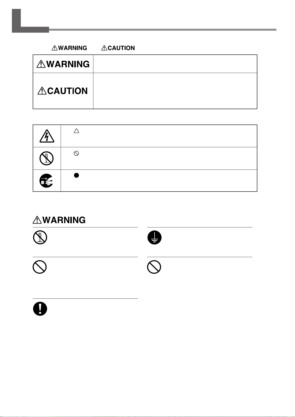
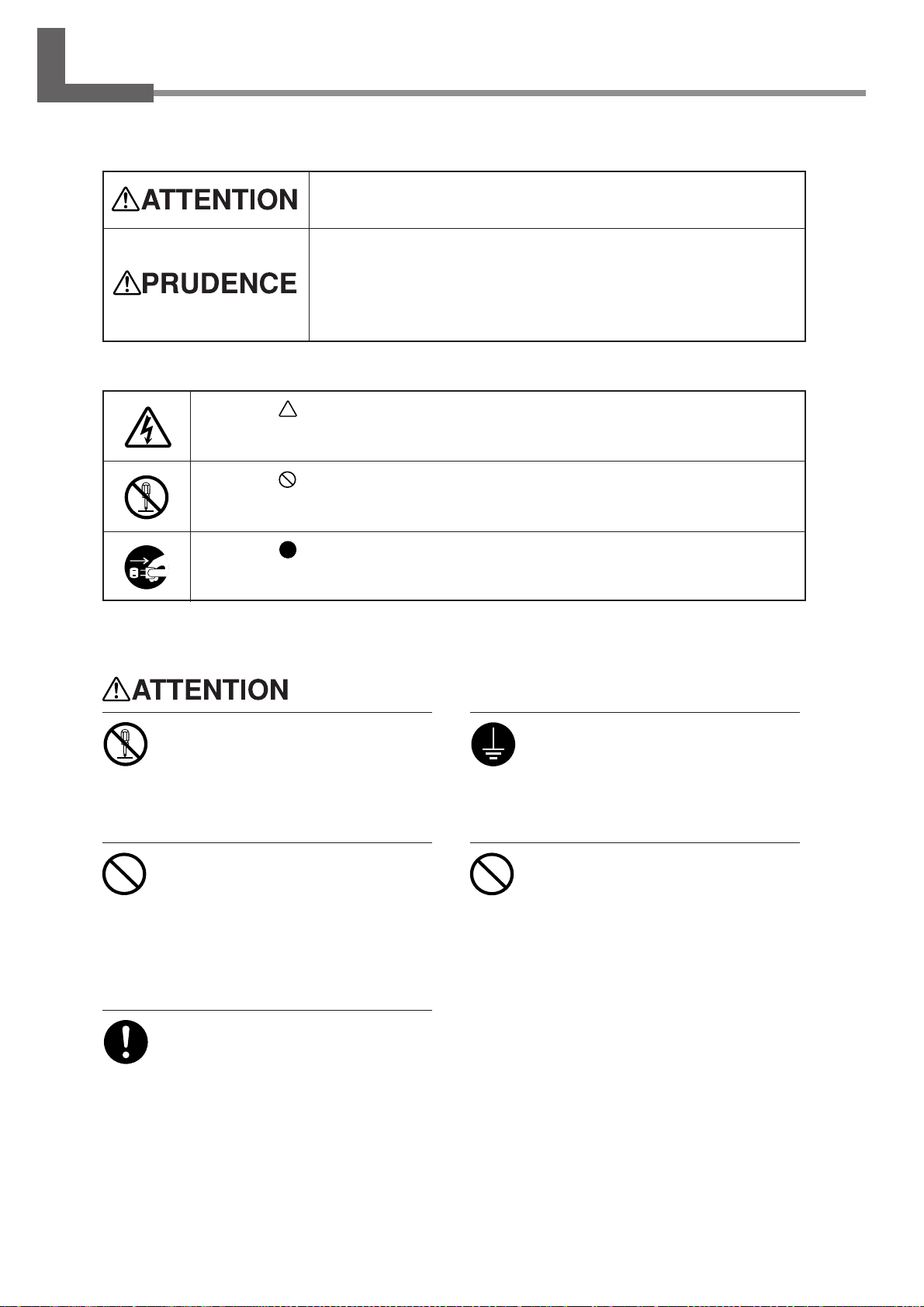
About and Notices
Used for instructions intended to alert the user to the risk of death or severe
injury should the unit be used improperly.
Used for instructions intended to alert the user to the risk of injury or material
damage should the unit be used improperly.
* Material damage refers to damage or other adverse effects caused with
respect to the home and all its furnishings, as well to domestic animals or
pets.
About the Symbols
The symbol alerts the user to important instructions or warnings. The specific meaning of
the symbol is determined by the design contained within the triangle. The symbol at left means
"danger of electrocution."
The symbol alerts the user to items that must never be carried out (are forbidden). The
specific thing that must not be done is indicated by the design contained within the circle. The
symbol at left means the unit must never be disassembled.
The symbol alerts the user to things that must be carried out. The specific thing that must
be done is indicated by the design contained within the circle. The symbol at left means the
power-cord plug must be unplugged from the outlet.
Do not disassemble, repair, or modify .
Doing so may lead to fire or abnormal operation resulting in injury.
Do not use with any electrical power
supply that does not meet the ratings
displayed on the unit.
Use with any other power supply may lead
to fire or electrocution.
Use only with the power cord included
Ground the unit with the ground wire.
Failure to do so may result in risk of electrocution in the event of a mechanical problem.
Do not use while in an abnormal state
(i.e., emitting smoke, burning odor,
unusual noise, or the like).
Doing so may result in fire or electrocution.
Immediately switch off the power , unplug the
power cord from the electrical outlet, and
contact your authorized Roland DG Corp.
dealer or service center.
with this product.
Use with other than the included power cord
may lead to fire or electrocution.
6
To Ensure Safe Use
Page 11
To Ensure Safe Use
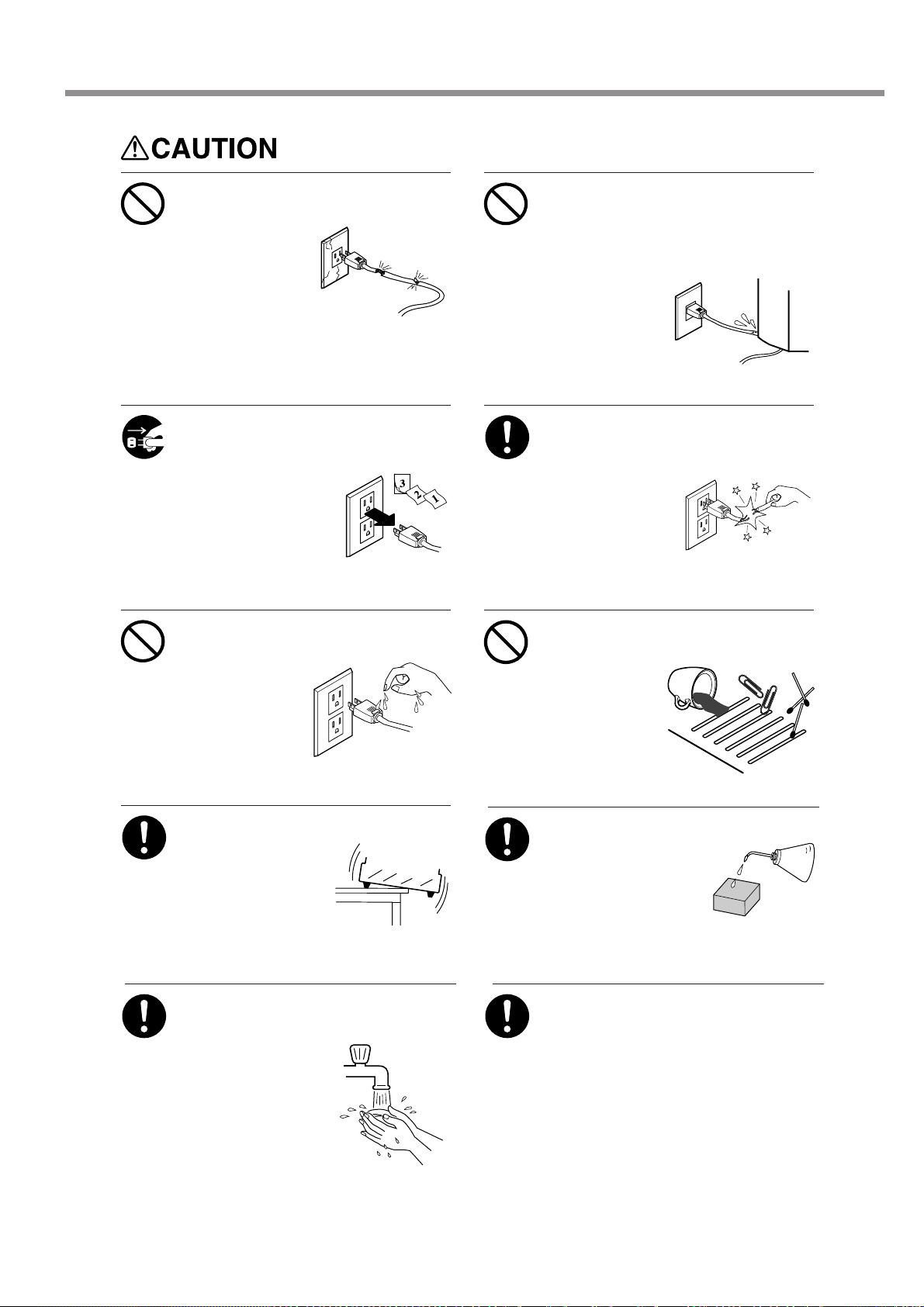
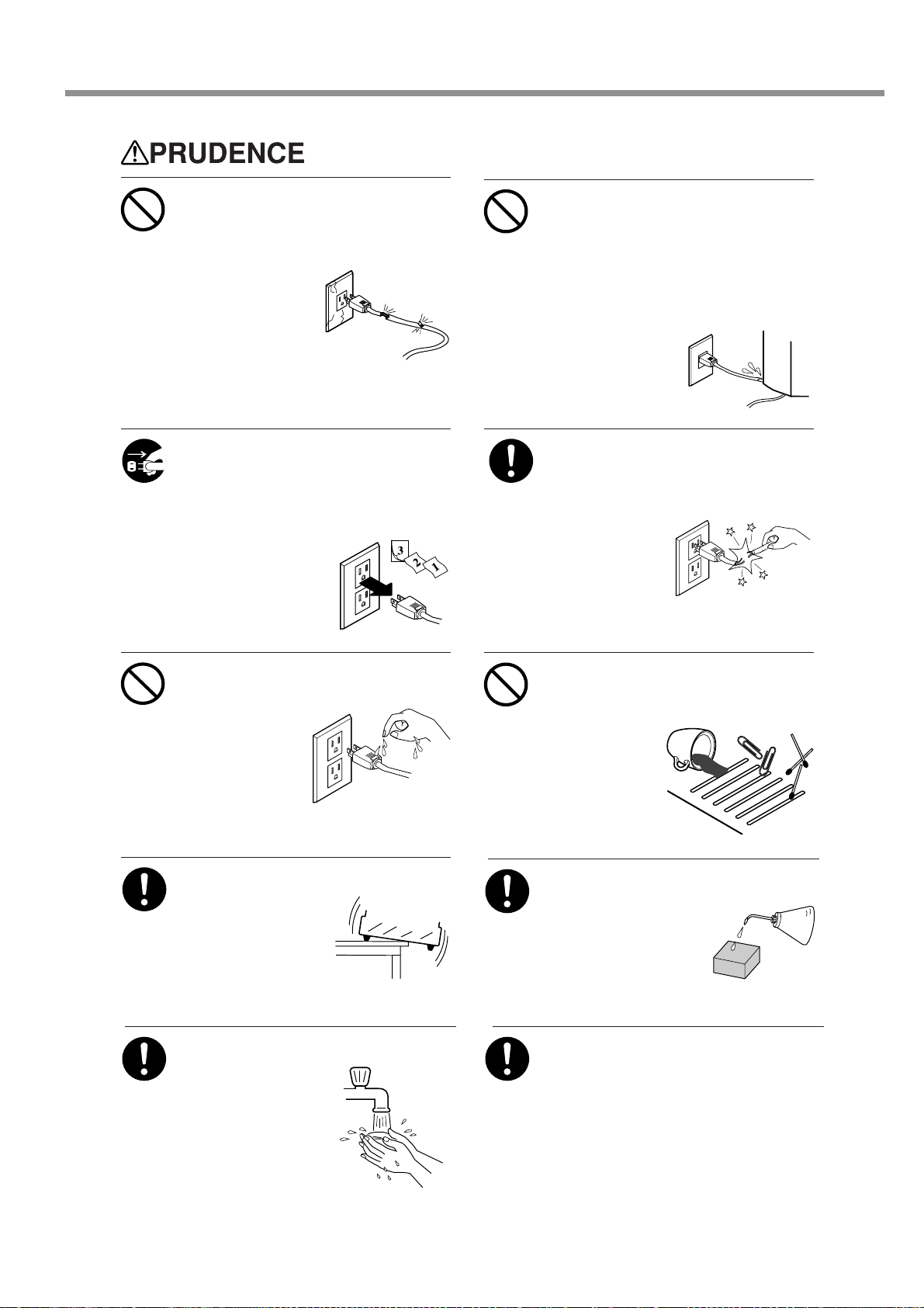
Do not use with a damaged power
cord or plug, or with a loose electrical outlet.
Doing so may lead to
fire, electrical shock,
or electrocution.
When not in use for extended periods,
unplug the power-cord plug from the
electrical outlet.
Failure to do so may result in danger of electrical shock, electrocution,
or fire due to deterioration
of electrical insulation.
Do not attempt to unplug the powercord plug with wet hands.
Doing so may result
in electrical shock
or electrocution.
Do not damage or modify the electrical power cord, subject it to excessive bending, twisting, pulling, binding, or pinching, or place any object
or weight on it.
Doing so may damage the electrical
power cord, leading
to fire, electrical
shock, or electrocution.
When unplugging the electrical power
cord from the power outlet, grasp the
plug, not the cord.
Unplugging by pulling
the cord may damage it, leading to fire,
electrical shock, or
electrocution.
Do not allow liquids, metal objects or
flammables inside the machine.
Such materials
can cause fire.
Install on a stable surface.
Failure to do so may
result in the unit tipping
over, leading to injury.
When you're finished, wash your
hands to rinse away all cuttings.
Perform dry cutting with no cutting oil.
Such materials can cause fire.
Please use a vacuum cleaner to remove cutting dust.
Do not use any blower like airbrush.
Otherwise, dust spread in the air may harm
your health.
To Ensure Safe Use
7
Page 12
To Ensure Safe Use
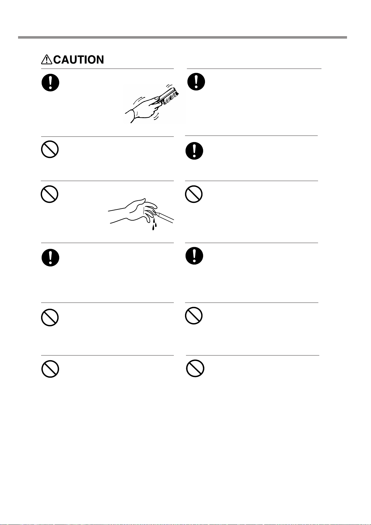
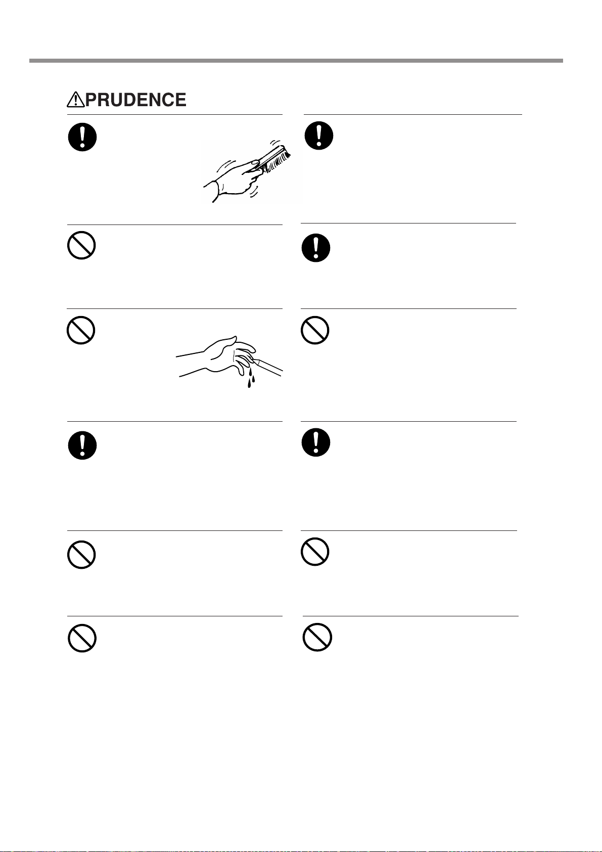
Use a commercially available brush
to remove metal cuttings.
Attempting to use a
vacuum cleaner to
take up metal cuttings
may cause fire in the
vacuum cleaner.
Do not carelessly insert the hands
while in operation.
Doing so may result in injury.
Do not touch the tip of the blade with
your fingers.
Doing so may
result in injury.
Wear dust goggles and mask during
use.
Cutting dust may scatter, causing bodily injury.
Unpacking, installation, and moving
are operations that must be carried out
by four or more persons.
Failure to do so may result in falling of the
unit, leading to injury.
Fasten the spindle, tool, and material
securely in place.
Otherwise they may come loose during cutting, resulting in injury.
Do not operate beyond capacity or
subject the tool to undue force.
The tool may break or fly off in a random direction. If cutting beyond capacity is mistakenly started, immediately turn off the EMERGENCY STOP switch.
Switch off the machine and unplug the
power cord from the electrical outlet
before performing cleaning or maintenance.
Failure to do so may result in injury or electrical shock.
Do not wear gloves, a necktie or widesleeved clothing.
They may become caught in the tool, resulting in injury.
Do not operate if a spindle cover is
cracked or broken.
If the spindle is cracked, contact a service
agent immediately for repairs.
Do not touch the tool immediately after cutting operating stops.
The tool may have become hot due to friction heat and may cause burns if touched.
Do not touch the spindle motor immediately after a cutting operation has
ended.
Doing so may result in burns.
8
To Ensure Safe Use
Page 13
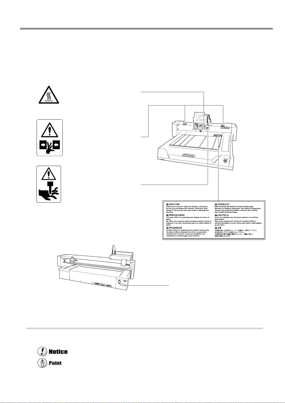
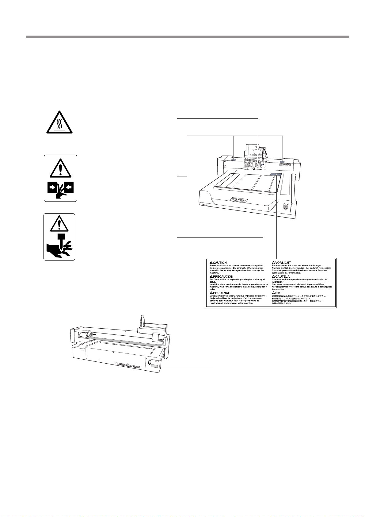
About the Labels Affixed to the Unit
These labels are affixed to the body of this product.
The following figure describes the location and content of these messages.
Caution: high temperatures. Do
not touch immediately after a cutting operation has ended.
Use care to avoid being pinched.
Keep hands away during operation.
To Ensure Safe Use
Use caution when handling or
working with the blade. Careless
handling may result in injury.
Model name
Rating plate
Use a rated power supply.
In addition to these symbols, the symbols shown below are also used.
: Indicates information to prevent machine breakdown or malfunction and ensure correct use.
: Indicates a handy tip or advice regarding use.
To Ensure Safe Use
9
Page 14
Pour utiliser en toute sécurité
Avis sur les avertissements
Utilisé pour avertir l'utilisateur d'un risque de décès ou de blessure grave en
cas de mauvaise utilisation de l'appareil.
Utilisé pour avertir l'utilisateur d'un risque de blessure ou de dommage
matériel en cas de mauvaise utilisation de l'appareil.
* Par dommage matériel, il est entendu dommage ou tout autre effet
indésirable sur la maison, tous les meubles et même les animaux
domestiques.
À propos des symboles
Le symbole attire l'attention de l'utilisateur sur les instructions importantes ou les
avertissements. Le sens précis du symbole est déterminé par le dessin à l'intérieur du triangle.
Le symbole à gauche signifie "danger d'électrocution".
Le symbole avertit l'utilisateur de ce qu'il ne doit pas faire, ce qui est interdit. La chose
spécifique à ne pas faire est indiquée par le dessin à l'intérieur du cercle. Le symbole à
gauche signifie que l'appareil ne doit jamais être démonté.
Le symbole prévient l'utilisateur sur ce qu'il doit faire. La chose spécifique à faire est
indiquée par le dessin à l'intérieur du cercle. Le symbole à gauche signifie que le fil électrique
doit être débranché de la prise.
Ne pas démonter, réparer ni modifier .
Démonter, réparer ou modifier l'appareil risque de provoquer un incendie ou de causer
un fonctionnement anormal entraînant des
blessures.
Ne pas utiliser avec une source
d'alimentation électrique non
conforme à la norme indiquée sur
l'appareil.
Utiliser l'appareil avec une autre source
d'alimentation risque de provoquer un
incendie ou de causer une électrocution.
Utiliser l'appareil uniquement avec le
fil électrique fourni.
Utiliser l'appareil avec un autre fil risque de
provoquer un incendie ou une électrocution.
Mettre l'appareil à la terre avec le fil
de mise à la terre.
Ne pas respecter cette consigne peut créer
un risque d'électrocution en cas de panne
mécanique.
Ne pas utiliser l'appareil s'il est dans
un état anormal (p.ex., émission de
fumée, odeur de brûlé, bruit inhabituel
ou autre anomalie).
Ne pas respecter cette consigne risque de
provoquer un incendie ou une électrocution.
Couper immédiatement l'alimentation
électrique, débrancher le fil de la prise et
communiquer avec le revendeur ou le centre de service autorisés de la société Roland
DG.
10
Pour utiliser en toute sécurité
Page 15
Pour utiliser en toute sécurité
Ne pas utiliser si le fil ou la fiche
électriques sont endommagés; ne
pas brancher dans une prise mal
fixée.
Négliger de suivre
cette consigne
risque de provoquer
un incendie ou
decauser une
décharge électrique
ou une électrocution.
Si l'appareil reste inutilisé pendant de
longues périodes, débrancher la fiche
de la prise.
Négliger de suivre cette consigne peut
créer un risque de décharge électrique ou
d'électrocution ou
provoquer un incendie
à cause de la
détérioration de
l'isolant électrique.
Ne pas endommager ni modifier le fil
électrique. Ne pas le plier, le tordre,
l'étirer , l'attacher ou le serrer de façon
excessive. Ne pas placer d'objet ou
de poids sur le fil.
Négliger de suivre cette consigne peut
endommager le fil électrique, ce qui risque
de provoquer un
incendie ou de
causer une
décharge électrique
ou une électrocution.
Pour débrancher l'appareil, saisir la
fiche et non le fil électrique.
Tirer sur le fil peut l'endommager, ce qui
risque de provoquer un incendie ou de
causer une
décharge
électrique ou une
électrocution.
Ne pas débrancher le fil avec des
mains mouillées.
Ne pas respecter
cette consigne risque de provoquer
des décharges
électriques ou une
électrocution.
Installer sur une surface stable.
Sinon, l'appareil risque
de se renverser et de
causer des blessures.
Quand vous avez terminé d'utiliser
l'appareil, laver vos
mains pour bien
enlever tous les
copeaux.
Ne pas laisser de liquides ni d'objets
métalliques ou inflammables
s'infiltrer dans l'appareil.
De telles infiltrations peuvent
provoquer un
incendie.
Faire des coupes à sec, sans huile de
coupe.
L'huile de coupe peut
provoquer un incendie.
Utiliser un aspirateur pour nettoyer
les copeaux. N'utiliser aucun appareil
soufflant de l'air comme un sèchecheveux.
La poussière répandue dans l'air pourrait
nuire à votre santé.
Pour utiliser en toute sécurité
11
Page 16
Pour utiliser en toute sécurité
Utiliser une brosse du commerce pour
retirer les rognures de métal.
Tenter de retirer les
rognures de métal à
l’aide d’un aspirateur
peut faire naître un
incendie dans
l’aspirateur.
Faire attention de ne pas insérer ses
mains pendant le fonctionnement.
Ne pas respecter cette consigne peut
provoquer des blessures.
Ne pas toucher à l’extrémité de la lame
avec vos doigts.
Vous risqueriez
de vous blesser
en y touchant.
Lorsque vous déplacez l'appareil, le
saisir par sa base en aluminium et le
transporter à 4 personnes ou plus.
Si l'appareil est saisi par la plaque du dessus,
il peut tomber et entraîner des blessures.
Fixer fermement le mandrin, l'outil et
le matériel à leur place.
Sinon, ces éléments risquent d'avoir du jeu
lors des coupes, ce qui entraînerait des
blessures.
Ne pas utiliser l'appareil au-dessus de
ses capacités ou le soumettre à une
force excessive.
L'outil pourrait se briser ou être projeté dans
une direction indéterminée. Si vous
commencez par inadvertance une coupe audessus de la capacité de l'appareil, l'éteindre
immédiatement à l'aide du bouton d'urgence.
Porter des lunettes de travail et un
masque durant l'utilisation.
Des copeaux pourraient être projetés et vous
blesser.
Ne pas porter de gants, de cravate ou
de vêtement à manches amples.
Ils pourraient se prendre dans l'appareil et
entraîner des blessures.
N'utilisez pas l'appareil si le couvercle
de l'axe est fissuré ou brisé.
Si le couvercle de l'axe est fissuré,
communiquez immédiatement avec un agent
de service pour faire effectuer les
réparations.
Couper le contact et débrancher le
câble d’alimentation du réceptacle
avant de procéder au nettoyage ou à
l’entretien de l’appareil.
Une négligence à ce niveau pourrait
provoquer des blessures ou une
électrocution.
Ne pas toucher l'outil immédiatement
après une coupe.
L'outil pourrait avoir chauffé avec la friction
et vous causer des brûlures.
Ne touchez pas le moteur de l'axe
immédiatement après avoir terminé
une coupe.
Vous risqueriez alors de vous brûler.
12
Pour utiliser en toute sécurité
Page 17
Pour utiliser en toute sécurité
À propos des étiquettes collées sur l'appareil
Ces étiquettes sont collées à l'extérieur de l'appareil.
Les dessins suivants indiquent l'endroit et le contenu des messages.
Attention : températures élevées.
Ne touchez pas immédiatement
après avoir effectué une coupe.
Soyez prudent et évitez les
pincements. Éloignez les mains
pendant le fonctionnement.
Soyez prudent lorsque vous
manipulez ou utilisez la lame,
sinon vous risquez de vous
blesser.
Nom du modèle
Étiquette des caractéristiques électriques
Utiliser l'alimentation appropriée
Pour utiliser en toute sécurité
13
Page 18

14
Page 19

1. Getting Started
This chapter describes the procedures extending from unpacking
the machine to installing it, and also explains such matters as required terminology and other background knowledge.
15
Page 20
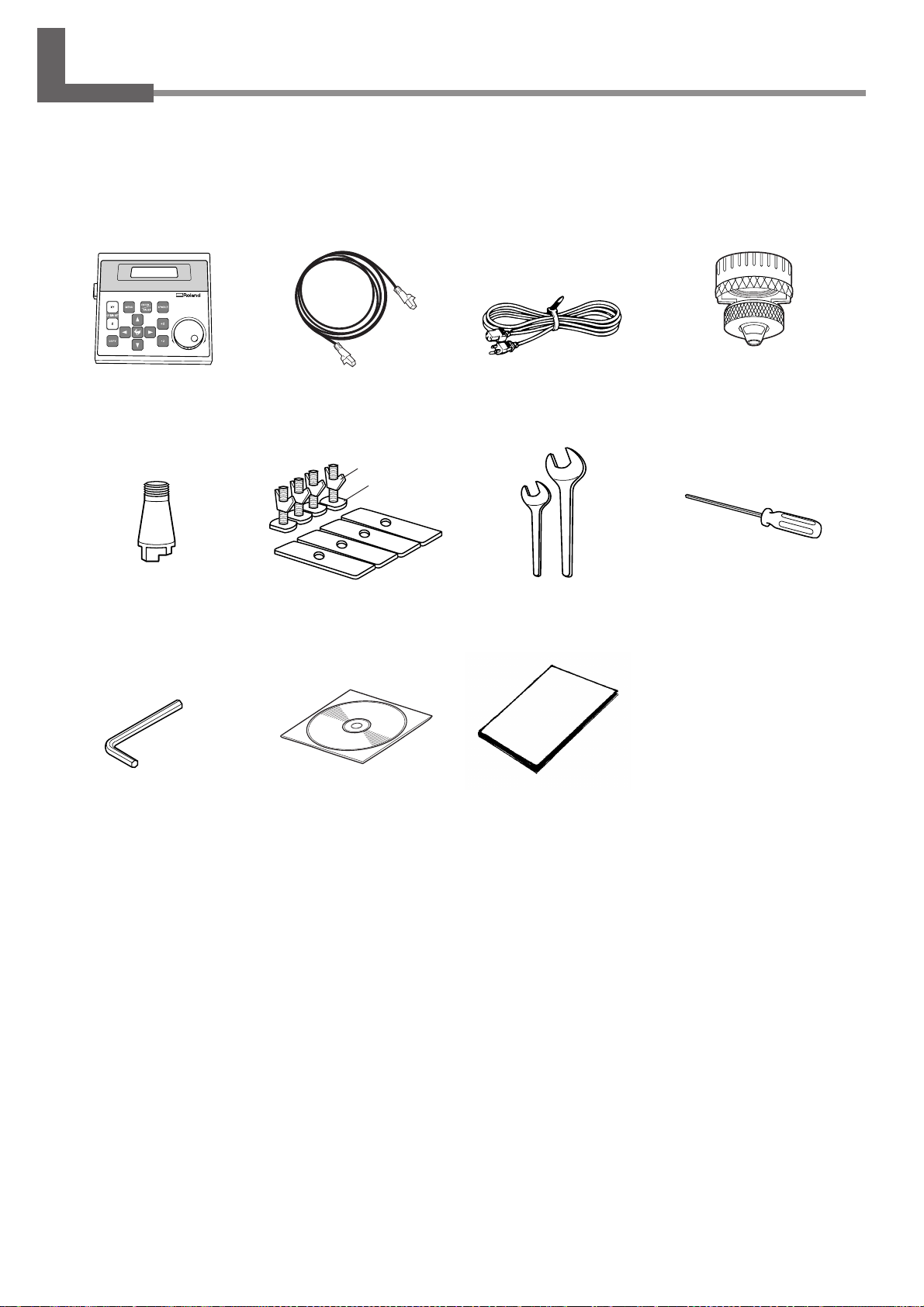
1-1. Included Items and Accessories
Follow the steps in "Unpacking and Repacking" on the packing carton to take out the included items and accessories.
Before you attempt installation, make sure all the included items are present.
Operation panel : 1 Operation-panel
connector cable : 1
Nut
Bolt
Solid collet : 1 (*1)
Hexagonal wrench
(3 mm) : 1
Clamps : 4 (*2)
Roland Software Package
CD-ROM : 1
Power cord : 1 Depth regulator
nose unit : 1
Wrenches
(17 mm : 1, 10 mm : 1)
User's Manual
(this manual) : 1
Hexagonal screw driver
(2 mm) : 1
16
*1 This is for diameter 4.36 mm character cutters and flat cutters. It cannot be used with diamond scrapers or end mills.
*2 The bolts and nuts are installed on the machine. (They are used for attaching the packing retainers.)
* This machine does not come with a cutter or cutter holder.
Chapter 1 - Getting Started
Page 21
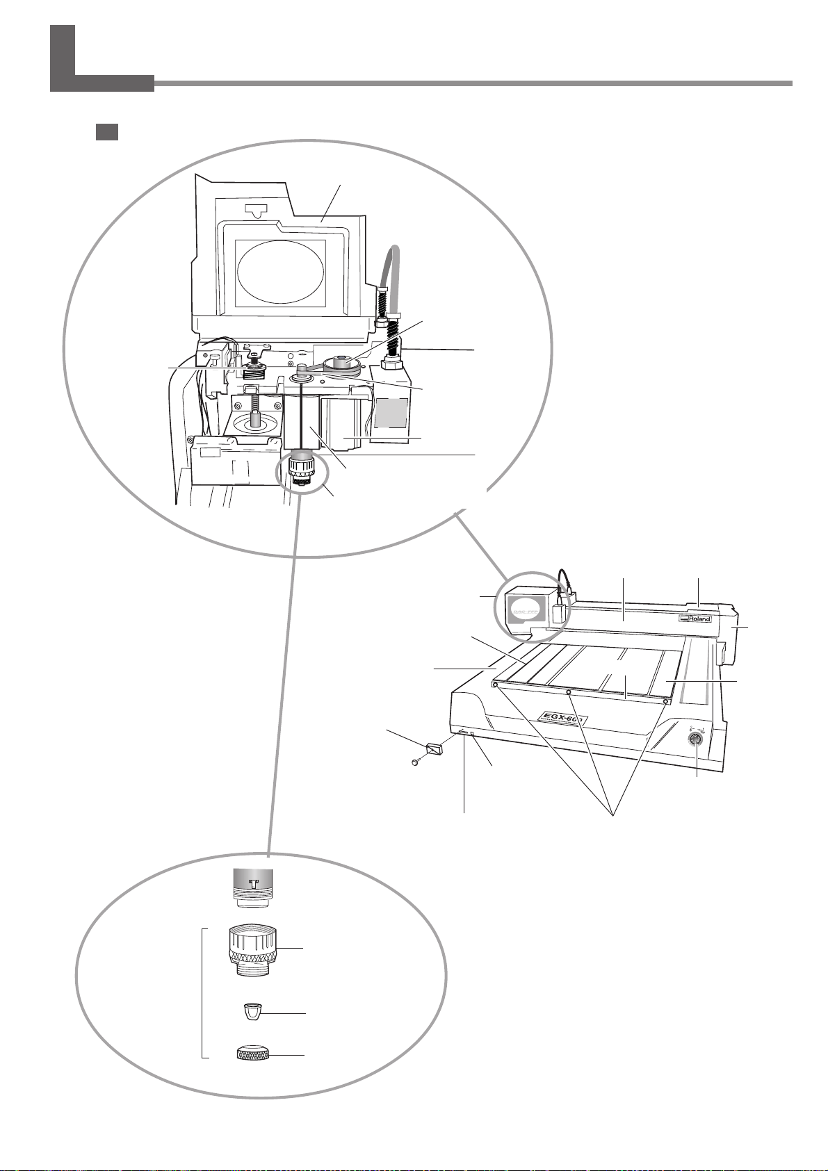
1-2. Names and Functions
Front
Spindle cover
Pulley
Lock nut
Belt
Spindle motor
Spindle unit
Depth regulator nose unit
(Nose unit)
Spindle head
T slot
Bed
Slot cover
Memory-card slot
Operation-panel
connector
Rail cover
Guide
Guide securing
screws
X-axis rail
Arm
Table
Emergency stop
switch
Depth regulator
nose unit
(Nose unit)
Micrometer dial
Nose cone
Retainer nut
Chapter 1 - Getting Started
17
Page 22
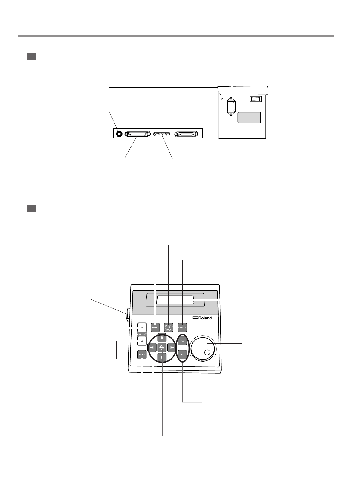
1-2. Names and Functions
Rear
Expansion connector 1
This connector is for transmitting the
rotation of the spindle to an external
device.
Parallel connector
This connector is for
connection to the printer
port on the computer.
Operation Panel
Power-cord connector
Expansion connector 2
This is for communication with an
external device using the teaching
feature.
Serial connector
This connector is for
connection to the COM
port on the computer.
ENTER/PAUSE button
This enables values you enter. Pressing it while
cutting is in progress pauses operation.
Power switch
Menu button
This displays the main menu.
Connector
X/Y-axis Origin Set button
This sets the reference point for the
cutting position.
Z-axis Origin Set button
This makes settings such as for the
reference point for aligning the
cutter.
Copy button
This calls up the menu for the copy
feature.
Movement buttons
These move the spindle head forward
and backward and to the left and right.
They are also used for menu operations.
Spindle button
This starts and stops rotation of
the spindle.
Display
Dial
This adjusts the spindle rotating
speed. It is also used for menu
operations.
Z-axis Movement buttons
These move the spindle head up
and down.
Feed button
This is used in combination with
the movement buttons.
18
Chapter 1 - Getting Started
Page 23
When the spindle motor is run at high speed while at a low temperature, rotation may be unstable for some time. In such
cases, allow to warm up by running at about 15,000 rpm with no load for around 15 minutes.
1-3. Installation and Cable Connections
Install on a stable surface.
Failure to do so may result in the unit tipping over, leading to injury.
Unpacking, installation, and moving are operations that must be carried out by four or more persons.
Failure to do so may result in falling of the unit, leading to injury.
Installation Site and Operating Environment
Use this machine in an environment that meets the following conditions.
• Temperature of 5 to 40 ˚C (41 to 104 ˚F) and relative humidity of 35 to 80% (with no condensation).
• A level location with no wobble.
• Little dust.
• Little vibration.
• Good ventilation and heat dissipation.
• Low electrical noise. For example, avoid installing near an electric motor.
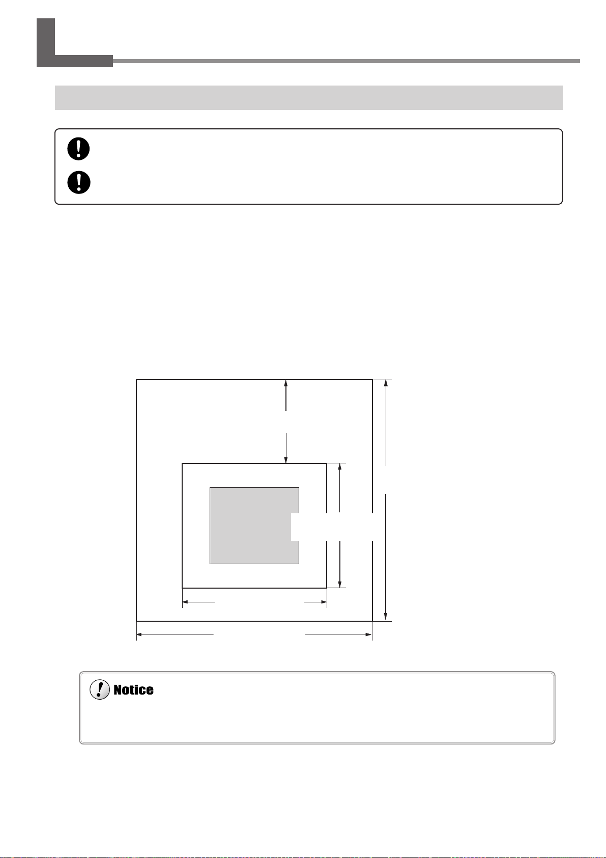
Also ensure that the following amount of space is available.
Maintenance space
Installation space
900 mm / 900 mm
(35 in./ 35 in.)
(Rear)
Main unit
(Front)
1200 mm / 1000 mm
(48 in./ 40 in.)
2100 mm / 1900 mm
(83 in./ 75 in.)
EGX-600 / EGX-400
2600 mm / 2500 mm
(103 in./ 100 in.)
1200 mm / 1000 mm
(48 in./ 40 in.)
Chapter 1 - Getting Started
19
Page 24

1-3. Installation and Cable Connections
Make sure the power to the machine is switched off before attempting to connect or disconnect the cables. Connect securely to ensure
that accidental disconnection does not occur during operation.
When the connection uses a serial cable, you need to make sure the communication parameters for the machine match the
communication parameters for the computer. For more information about the computer's communication parameters, refer to
the documentation for the program. The defaults for the programs included with this machine are set up to match without
modification.
Configuring the Communication Parameters for the Machine
☞ See p.109 "I/O Submenus"
Ground the unit with the ground wire.
Failure to do so may result in risk of electrocution in the event of a mechanical problem.
Use only with the power cord included with this product.
Use with other than the included power cord may lead to fire or electrocution.
Do not use with any electrical power supply that does not meet the ratings displayed on the unit.
Use with any other power supply may lead to fire or electrocution.
Connecting the Cables
Connect the operation panel and the power cable. If you're using a computer, then also connect a printer cable or serial
cable.
The printer cable or serial cable is sold separately. Use a cable that is compatible with the computer.
Printer cable
Use a commercially available printer cable.
Serial cable
If your computer is an IBM AT-compatible personal computer, then use an optionally available XY-RS-34 cable (or
equivalent). A straight cable such as a modem cable will not work.
20
Chapter 1 - Getting Started
Page 25
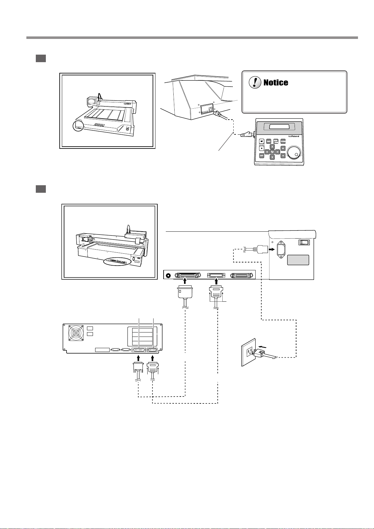
Do not insert an Ethernet cable or connect to a modular jack.
Front
Rear
1-3. Installation and Cable Connections
Insert until it clicks
into place.
Operation-panel
connector cable
Parallel
connector
Secure with
the clips.
Serial portPrinter port
Printer cable
Connect either a printer cable or
serial cable.
Serial
connector
Serial cable
Power connector
Secure with
the screws.
Power outlet
Power cord
Chapter 1 - Getting Started
21
Page 26

22
Page 27

2. Basic Operation
Operating the buttons makes the machine move. When operating the
buttons, be sure to keep your hands away from the machine.
Do not let your hair, necktie, or the like touch the machine. There is
danger of becoming it caught on the spindle or other moving parts.
This chapter describes what you should know before you try to use
the machine, such as the most basic operations and the procedures
for safe use and handling. Be sure to read this chapter before you go
on to the next step.
23
Page 28
2-1. Emergency Stop to Ensure Safety
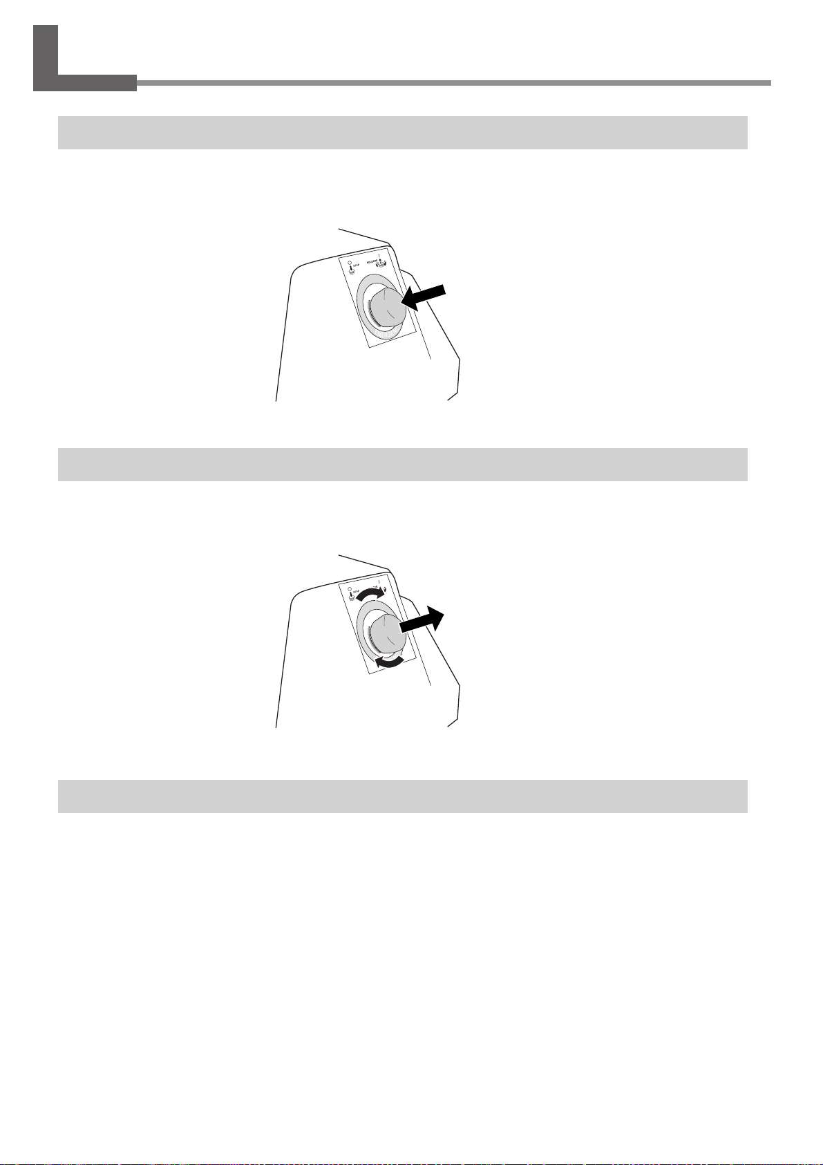
How to Perform an Emergency Stop
To stop the machine in an emergency in order to avoid danger, press the emergency stop switch. The machine immediately stops operating and quits cutting. Cutting cannot be resumed.
To Cancel an Emergency Stop
To cancel an emergency stop, turn the emergency stop switch in the direction of the arrow. The machine returns to the
state it was in immediately after powerup.
Opening and Closing the Spindle Cover
Be sure to close the spindle cover before you start cutting, and never open it while operation is in progress. For safety,
opening the spindle cover during operation causes an emergency stop. To recover, switch off the power to the machine.
When the spindle cover is open, only head movement using the movement buttons is possible. You cannot use the buttons
to rotate the spindle or perform cutting.
24
Chapter 2 - Basic Operation
Page 29
2-2. Switching the Power On and Off
Keep your hands away from the machine when you turn on the power. Also, do not place and objects
where they may obstruct the operation of the spindle head, X-axis rail, bed, or other components.
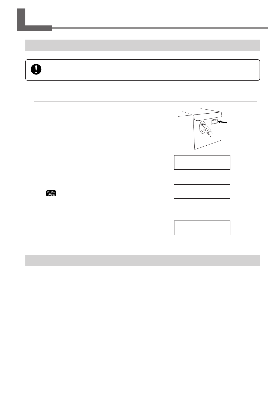
Switching On the Power
Turning On the Power
Turn on the power switch on the back of the
1
machine.
The display shows the model name, and while this is displayed, internal initialization is performed. This takes
about ten seconds.
EGX-600
Roland DG Corp.
When the screen shown at right appears, press
2
3
.
This machine operates at this time. The spindle head
moves to the left and back (to the VIEW position), then
stops.
The display changes to the top screen, and
startup ends.
Hit "ENTER" key
X 0 Y 40700
Z 0 8000RPM
Switching Off the Power
Turn off the power switch on the back of the machine. Do not the emer gency stop switch for turning the power on and off
in day-to-day use.
Chapter 2 - Basic Operation
25
Page 30
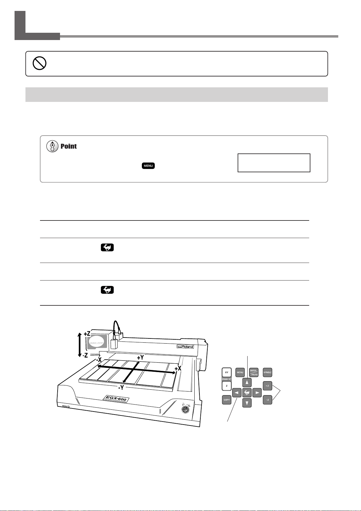
2-3. Moving the Spindle Head
Do not put the operation panel on the machine while operation. Doing so may result in unexpected problems.
Make sure the display shows the top screen. You cannot perform movement
when any other screen is displayed. Press
several times to display the
top screen.
Moving the Spindle Head
The spindle head moves in three directions, along the X, Y, and Z axes. When the display shows the top screen, pressing
the movement buttons effects movement in the corresponding directions.
X 0 Y 0
Z 0 8000RPM
The speed of movement is determined by how you press the movement buttons, as described below.
Pressing and holding down a movement button
While holding down , pressing and holding down
a movement button
Pressing and releasing a movement button
While holding down , pressing and releasing
a movement button
Slow continuous movement
Fast continuous movement
Movement of 0.01 mm per press
Movement of 0.1 mm per press
Y-axis direction
26
Chapter 2 - Basic Operation
Z-axis direction
X-axis direction
Page 31
2-3. Moving the Spindle Head
Moving the Spindle Head Out of the W ay Quickly
This feature moves the spindle head directly to the back-left position of the table (the VIEW position). This is handy
when loading or detaching a workpiece.
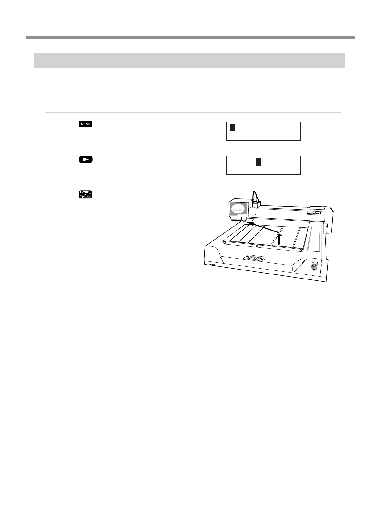
Moving to the VIEW Position
Press until the screen shown at right ap-
1
pears.
Press .
2
The blinking cursor moves to [VIEW].
Press .
3
The spindle head rises to the highest point, then moves
to the VIEW position.
HOME VIEW
Z1 Z0 Z2
HOME VIEW
Z1 Z0 Z2
Chapter 2 - Basic Operation
27
Page 32

2-4. Starting and Stopping Spindle Rotation
When the spindle cover is open, the spindle does not rotate.
A void turning the dial while cutting is in progress. The feed rate drops
momentarily, and the finished results of engraving may be adversely
affected.
Using Buttons to Start and Stop Rotation
Holding down for 0.5 seconds or longer makes the spindle rotate. Pressing it again stops rotation.
Adjusting the Spindle Rotating Speed
T o adjust the spindle rotating speed, you use the dial on the operation panel. The top screen displays the spindle rotating
speed.
Slow
Spindle rotating speed
Fast
28
Chapter 2 - Basic Operation
Page 33

2-4. Starting and Stopping Spindle Rotation
Forced Stop of Spindle Rotation
With this machine, you can set whether or not the spindle rotates. When it is set to rotate, rotation automatically starts
when a command is received from the computer and stops when cutting ends. When set not to rotate, no rotation at all
takes place. (Rotation does not occur even if you press .)
You use this feature at times such as when you are performing scribing using a diamond scraper.
Making the Setting for Spindle Rotation
Press until the screen shown at right
1
appears.
Press .
2
The blinking cursor moves to [OTHERS].
Press .
3
The screen for setting spindle rotation appears.
Use to move the blinking cursor to
4
[ON] or [OFF]. Press .
[ON] makes the setting for rotation, and [OFF] makes
the setting for forced stop.
I/O OTHERS
TEACHING SELF
I/O OTHERS
TEACHING SELF
REVOLUTION
<ON> OFF
Chapter 2 - Basic Operation
29
Page 34

2-5. Menu Operations
For detailed information on using the menus
☞ See p.104 "Menu Flowchart"
☞ See p.108 "Detailed Description of the Menus"
Displaying the Menus
All settings for this machine are made using menus. Pressing the following buttons displays the menu screens.
Main menu
Pause menu (when pressed during cutting)
Copy menu
Basic Menu Operations
X/Y-axis origin-point setting menu
Z-axis origin-point setting menu
When you display the menus, the buttons function as follows.
Moving to the next screen
Pressing this several times eventually returns you to the top screen.
Moving the blinking cursor
You use the blinking cursor to select items. In the example at right,
for instance, you can select either [ON] or [OFF].
Raising and lowering numerical values
Pressing either of these buttons while holding down increases or decreases the value by large amounts. Holding down the button makes the value change rapidly.
Confirming and executing the selected item
Operations with do not enable settings, they only select the setting values. A setting is
enabled only when you press . When you enable a setting, the item is displayed enclosed in "< >." You also use
this button to execute things and display submenus.
REVOLUTION
<ON> OFF
30
Chapter 2 - Basic Operation
Page 35

2-6. Care and Handling of Memory Cards
This machine does not detect the write-protect
switch on an SD Memory Card, even when the
switch is set to "LOCK."
Windows must be able to treat the memory card as a single volume. Nearly all memory-card writers that are compatible with
Windows meet this requirement.
This section describes the basic usage and handling of memory cards.
This machine can execute cutting data saved on a memory card, and can save sequences created using the teaching
feature. For more information about these operations, see "Executing Cutting Data Saved on a Memory Card" on p.65
and "The Teaching Feature" on p.71.
Types of Memory Cards You Can Use
Use commercially available "SD (Secure Digital) Memory Card" or "MultiMediaCard", which are available in sizes of
16 MB, 32 MB, and 64 MB. Note that copyright-protection functions are not used with this machine.
Roland DG Corp. has verified the operation of the following memory cards.
Manufacturer Part number Capacity
SanDisk SDMB-16 16 MB
SDMB-32 32 MB
SDMB-64 64 MB
Panasonic RP-SD016 16 MB
RP-SD032 32 MB
RP-SD064 64 MB
HAGIWARA SYS-COM HPC-MC32M 32 MB
HPC-MC64M 64 MB
Memory-card Writers You Can Use
To save cutting data on a memory card or to format a memory card, you use a commercially available memory-card
writer or adapter. One that meets the following specifications is required.
• Compatible with "SD Memory Card" or "MultiMediaCard" you're using
• Able to be connected to your computer running Windows
• Able to read and write files compatible with Windows
Roland DG Corp. has verified the operation of the following memory-card writers.
Manufacturer Part number Operating environment
VICS Technology RD5 Windows 98/Me/2000/XP
Chapter 2 - Basic Operation
31
Page 36
2-6. Care and Handling of Memory Cards
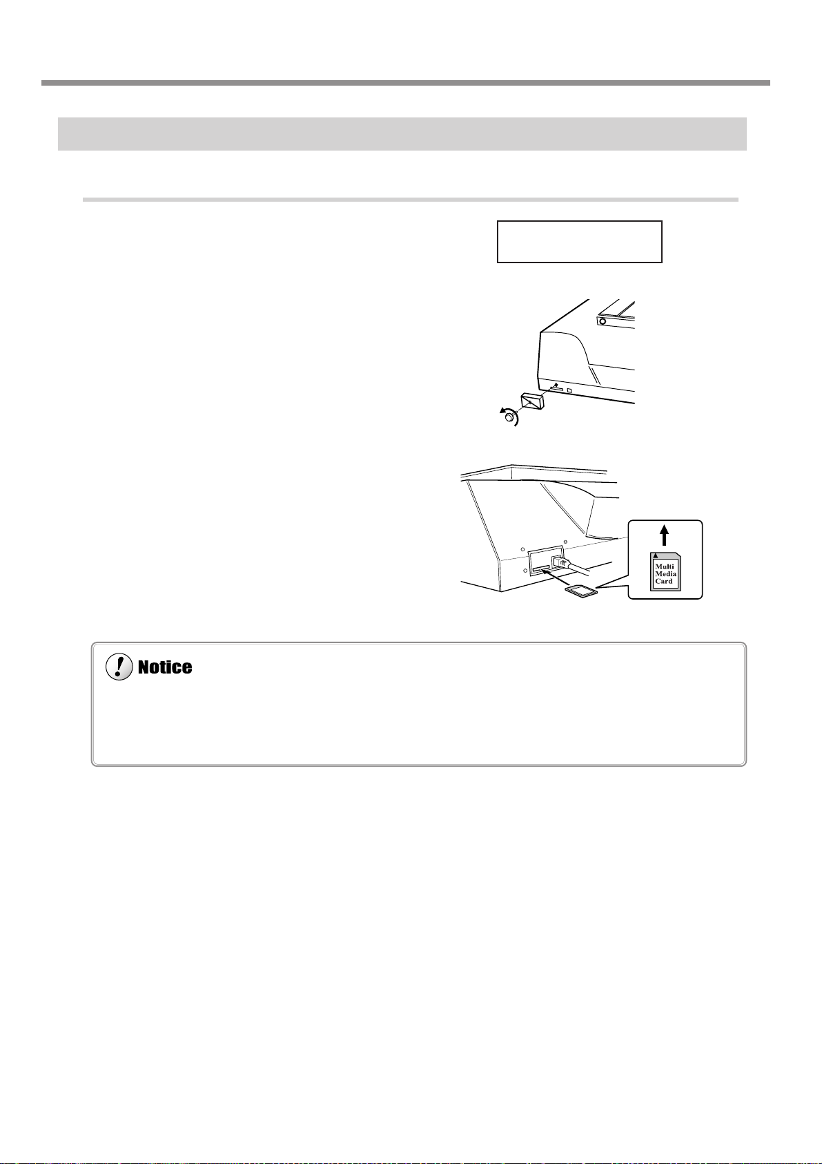
◆ Be careful to orient the memory card correctly when inserting it. An incorrectly inserted card will not function and may
even cause breakdown.
◆ Before you insert a memory card, carefully clean away any cutting waste from the memory card and the area around the
memory-card slot.
Inserting and Removing a Memory Card
Inserting a Memory Card
Make sure the display shows the top screen.
1
Remove the slot cover.
2
Hold the card with the label side facing up and
3
the notch on the right, and insert it into the
memory-card slot. Press it in gently until it clicks
into place.
Attach the slot cover.
4
X 0 Y 40700
Z 0 8000RPM
32
Chapter 2 - Basic Operation
Page 37

Removing a Memory Card
Do not switch off the power while a memory card is being accessed.
Do not switch off the machine while the display shows a message such as [Now Processing]. Doing so may result in data
corruption or malfunction.
Do not insert or remove a memory card in any of the following circumstances.
◆ After you turn on the machine and before the top screen appears
◆ While the memory card is being accessed (When the display shows a message such as [Now Processing])
◆ While a screen for dating or calling up data is displayed (When the display shows a message such as [Select File])
Doing so may result in data corruption, failure to display the correct file names, or malfunction.
2-6. Care and Handling of Memory Cards
Make sure the display shows the top screen.
1
Remove the slot cover.
2
Gently press the card in until it clicks into place,
3
then pull it out from the memory-card slot.
Attach the slot cover.
4
X 0 Y 40700
Z 0 8000RPM
1. 2.
Chapter 2 - Basic Operation
33
Page 38

2-6. Care and Handling of Memory Cards
Formatting deletes all data saved on the memory card. Before you format the card, make sure that it contains no data you want
to keep.
Formatting a Memory Card
Formatting a memory card is normally not necessary. However, the machine may be unable to use a memory card that
has been reformatted for use with another device, such as a digital camera. In such cases, use the following method to
reformat the card again.
Performing Formatting
To perform formatting, you use a memory-card writer. For information on the specific method, refer to the documentation for the memory-card writer you're using. Also, give attention to the following points when formatting.
For a MultiMediaCard
Use the standard formatter for Windows. (That is, use the same operation as for formatting a floppy disk.) Depending on
the version of Windows you're using, you may be able to choose the file system to use for formatting. In such cases, be
sure to select FAT. Do not format as FAT32 or NTFS.
For an SD (Secure Digital) Memory Card
Perform formatting using the same method as for a MultiMediaCard. If a dedicated SD formatter is available, then use
that.
34
Chapter 2 - Basic Operation
Page 39

3. Preparations
This chapter describes how to install a cutter , how to load a workpiece,
and other preparations you make before you carry out cutting.
35
Page 40

3-1. Selecting the Cutter Installation Method
Cutter Types and What They Are Suited For
You can install any of a wide variety of tools on this machine. You can also choose whether to use the depth regulator
nose unit (nose unit). Choose a tool suited to the task at hand, and decide whether to use the nose unit.
Tool
Character cutter
Flat cutter
Diamond scraper (*2)
With nose unit
◆ Engraving acrylic and other (*1)
plastic plates
☞ p.37 "Cutter Installation Method 1"
◆ Unsuitable
No nose unit
◆ Engraving plates of aluminum or brass
◆ Three-dimensional engraving and creating
reliefs using plastic materials
☞ p.42 "Cutter Installation Method 2"
◆ Scribing plates of aluminum or brass (*2)
☞ p.46 "Cutter Installation Method 3"
End mill (*3)
*1 Use of the nose unit may not be suitable when performing raised engraving of text or flat-drag cutting over a large surface area.
In such cases, use without the nose unit.
*2 This is suited to relatively small text and can produce finished results that are more attractive and have less burring than
engraving with a character cutter. An optionally available solid collet for diamond scrapers is required to install a diamond
scraper.
*3 An optionally available collet set for end mills is required to install an end mill.
◆ Unsuitable
◆ Creating reliefs and performing 3D cutting
using plastic materials
☞ p.51 "Cutter Installation Method 4"
36
Chapter 3 - Preparations
Page 41

Lock nut : Loosen
[AUTO Z CONTROL] : ON
[REVOLUTION] : ON
3-2. Cutter Installation Method 1 (With Nose Unit)
This is for when you perform engraving using the nose unit on an acrylic plate or the like. The tip of the nose traces the
material surface, which facilitates obtaining a uniform cutting-in depth. The tool used is a character cutter or a flat cutter .
This method is not suitable for aluminum, brass, or other materials that are easily scratched.
Character cutter or flat cutter
Lock nut
Cutter holder
(included with a character cutter or flat cutter)
Tool securing
screw
Chapter 3 - Preparations
37
Page 42

3-2. Cutter Installation Method 1 (With Nose Unit)
The cutter holder is reverse-threaded (that is, you turn
it counterclockwise to tighten it). Be careful to turn it
in the correct direction.
While installing the cutter, do not allow the operation panel to be touched inadvertently. When using the
operation panel, keep hands away from moving areas of the machine. Unintended operation of the ma-
chine may lead to danger of becoming caught.
Do not touch the tip of the cutter. Doing so may result in injury.
Securely fasten the cutter and workpiece in place. Otherwise they may come loose during cutting, resulting
in injury.
Installing a Character Cutter (With Nose Unit)
1. Installing the Cutter Holder and Collet
Open the spindle cover.
1
While using a wrench (17 mm) to keep the
2
spindle immobile, tighten the cutter holder securely.
Insert the included solid collet from below. While
3
gently holding the collet in place, turn the
spindle by hand until it is finger-tight.
3.
2.
1.
Use the included wrench to tighten the collet.
4
The correct tightening torque is 32 kgf-cm.
38
Chapter 3 - Preparations
Page 43

2. Nose-unit Installation and Menu Settings
Be sure to loosen the lock nut.
Install the nose unit. Tighten fully, then loosen
5
two turns.
Fully loosen the lock nut.
6
3-2. Cutter Installation Method 1 (With Nose Unit)
Use the menus to set [AUTO Z CONTROL] to ON.
7
(1) Press several times to display the screen shown at right.
(2) Press
(3) Press
(4) Press to move the blinking cursor to [ON], then press .
Use the menu to set [REVOLUTION] to ON.
8
(1) Press several times to display the screen shown at right.
(2) Press
(3) Press to move the blinking cursor to [ON], then press .
Press several times to return to the top screen.
9
to move the blinking cursor to [OTHERS], then press .
several times to display the screen shown at right.
to move the blinking cursor to [OTHERS], then press .
I/O OTHERS
TEACHING SELF
AUTO Z CONTROL
<ON> OFF
I/O OTHERS
TEACHING SELF
REVOLUTION
<ON> OFF
X 0 Y 0
Z 0 8000RPM
Chapter 3 - Preparations
39
Page 44
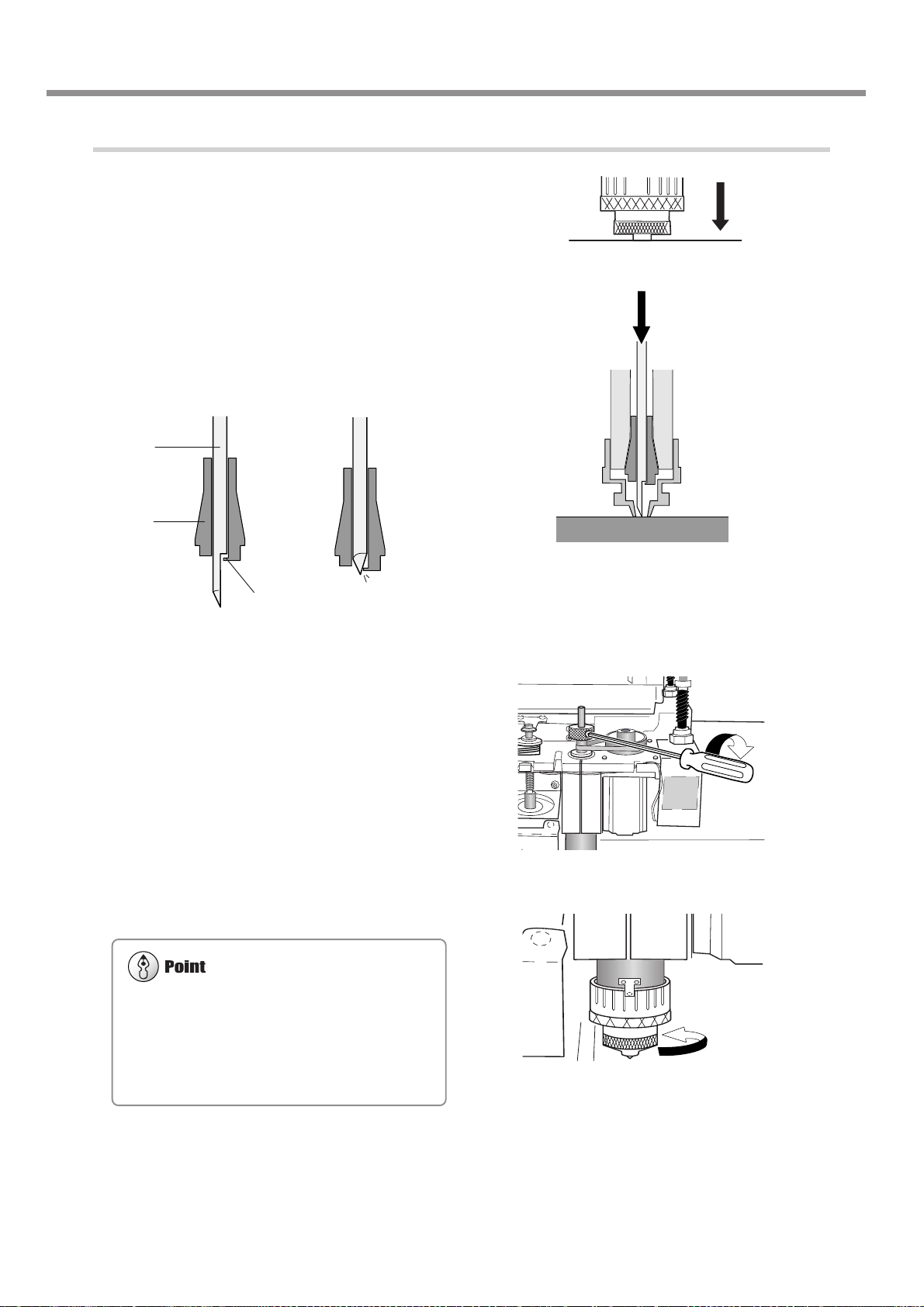
3-2. Cutter Installation Method 1 (With Nose Unit)
The amount you tighten the nose unit determines the
cutting-in depth. Adjust it to suit the task. An amount
of 4 to 8 scale ticks corresponds to 0.1 to 0.2 mm (0.004
to 0.008 in.). One scale tick is 0.0254 mm (0.001 in.),
and one full turn is 25 scale ticks, or 0.635 mm (0.025
in.).
3. Cutter Installation and Alignment
10
11
Lower the spindle until the tip of the nose unit
touches the table.
When the nose touches the table, operation stops automatically.
Insert the cutter (diameter 4.36 mm), then bring
the tip lightly into contact with the table.
When you insert the cutter, orient it so that it will not
catch on the collet.
Yes No
Cutter
Collet
Stopper
12
13
Use the included hexagonal screwdriver to
tighten the tool securing screw. Raise the
spindle.
Tighten the nose unit by 4 to 8 ticks on the scale.
40
Chapter 3 - Preparations
Page 45

3-2. Cutter Installation Method 1 (With Nose Unit)
For more information about how to set the cutting parameters
☞ See p.59 "Setting the Cutting Parameters"
☞ See p.134 " Examples of Settings for Cutting Parameters"
For detailed information about the nose unit
☞ See p.110 "Detailed Description of the Menus," the section " AUTO Z CONTROL "
☞ See p.103 "Detailed Description of the Nose Unit"
14
Close the spindle cover.
1.
3.
2.
Cutting Parameters When Using the Nose Unit
When you use the preceding method, there is no need to set the cutting-in depth or the cut-out amount by a software or
the operation panel. The cutting-in depth is determined mechanically by the amount of tightening of the nose unit.
Chapter 3 - Preparations
41
Page 46

3-3. Cutter Installation Method 2 (No Nose Unit)
This is for when you perform engraving without using the nose unit. The tool used is a character cutter or a flat cutter.
This method does not scrape the workpiece, so it is suitable for aluminum, brass and other materials that are easily
scratched. Note, however, that in order to obtain a uniform cutting-in depth, the thickness of the workpiece must also be
uniform.
Lock nut : Tighten
[AUTO Z CONTROL] : OFF
[REVOLUTION] : ON
Character cutter or flat cutter
Lock nut
Cutter holder
(included with a character cutter or flat cutter)
Tool securing
screw
42
Chapter 3 - Preparations
Page 47

3-3. Cutter Installation Method 2 (No Nose Unit)
The cutter holder is reverse-threaded (that is, you turn it
counterclockwise to tighten it). Be careful to turn it in
the correct direction.
While installing the cutter, do not allow the operation panel to be touched inadvertently. When using the
operation panel, keep hands away from moving areas of the machine. Unintended operation of the ma-
chine may lead to danger of becoming caught.
Do not touch the tip of the cutter. Doing so may result in injury.
Securely fasten the cutter and workpiece in place. Otherwise they may come loose during cutting, resulting
in injury.
Installing a Character Cutter (With No Nose Unit)
1. Installing the Cutter Holder and Collet
Open the spindle cover.
1
While using a wrench (17 mm) to keep the
2
spindle immobile, tighten the cutter holder securely.
Insert the included solid collet from below. While
3
gently holding the collet in place, turn the
spindle by hand until it is finger-tight.
3.
2.
1.
Use the included wrench to tighten the collet.
4
The correct tightening torque is 32 kgf-cm.
Chapter 3 - Preparations
43
Page 48

3-3. Cutter Installation Method 2 (No Nose Unit)
Be sure to set [AUTO Z CONTROL] to OFF.
2. Menu Settings
Fully tighten the lock nut.
5
Use the menus to set [AUTO Z CONTROL] to OFF.
6
(1) Press several times to display the screen shown at right.
(2) Press
(3) Press
(4) Press to move the blinking cursor to [OFF], then press .
Use the menu to set [REVOLUTION] to ON.
7
(1) Press several times to display the screen shown at right.
(2) Press
(3) Press to move the blinking cursor to [ON], then press .
to move the blinking cursor to [OTHERS], then press .
several times to display the screen shown at right.
to move the blinking cursor to [OTHERS], then press .
I/O OTHERS
TEACHING SELF
AUTO Z CONTROL
ON <OFF>
I/O OTHERS
TEACHING SELF
REVOLUTION
<ON> OFF
Press several times to return to the top screen.
8
44
Chapter 3 - Preparations
X 0 Y 0
Z 0 8000RPM
Page 49
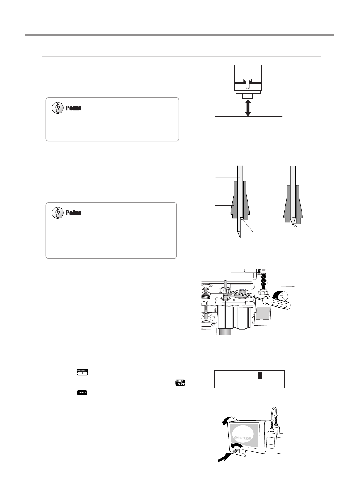
3. Cutter Installation and Alignment
For information on how to load material
☞ p.55 "Loading Material and Setting the Reference
Point for Cutting"
Damage to the workpiece can be prevented by placing a
sheet of thin paper over the workpiece. When you do
this it is a good idea to cut in by a depth increased by an
amount equal to the thickness of the paper (about 0.002
in.).
Load the workpiece, then move the spindle to
9
above the workpiece. Lower the spindle until
the tip of the collet is at a height about 12 to 13
mm (1/2 in.) from the surface of the material.
3-3. Cutter Installation Method 2 (No Nose Unit)
12 to 13 mm (1/2 in.)
10
11
Insert the cutter (diameter 4.36 mm), then bring
the tip lightly into contact with the workpiece.
When you insert the cutter, orient it so that it
will not catch on the collet.
If the cutter does not reach the workpiece, lower the
spindle further.
Use the included hexagonal screwdriver to
tighten the tool securing screw.
Yes No
Cutter
Collet
Stopper
12
13
Use the menus to set the height reference point (Z0).
(1) Press .
(2) Make sure the blinking cursor is at [Z0], then press .
(3) Press
Close the spindle cover.
to return to the top screen.
SET Z1 Z0 Z2
SURFACE < 0 >
1.
3.
2.
Chapter 3 - Preparations
45
Page 50

3-4. Cutter Installation Method 3 (Diamond Scraper)
This is for when you scribe aluminum or brass plates. The tool used is a diamond scraper , and the spindle is not rotated.
Engraving is performed by scraping the workpiece, so it achieves attractive finished results with little burring, but it does
not obtain deep cutting-in.
An optionally available solid collet for diamond scrapers is required to install a diamond scraper.
Lock nut: Loosen
[AUTO Z CONTROL]: ON
[REVOLUTION]: OFF
Diamond scraper
Lock nut
Cutter holder (included with a diamond scraper)
Tool securing
screw
Solid collet for a diamond scraper (optional)
46
Chapter 3 - Preparations
Page 51

Installing a Diamond Scraper
The cutter holder is reverse-threaded (that is, you turn
it counterclockwise to tighten it). Be careful to turn it
in the correct direction.
While installing the cutter, do not allow the operation panel to be touched inadvertently. When using the
operation panel, keep hands away from moving areas of the machine. Unintended operation of the ma-
chine may lead to danger of becoming caught.
Do not touch the tip of the cutter. Doing so may result in injury.
Securely fasten the cutter and workpiece in place. Otherwise they may come loose during cutting, resulting
in injury.
1. Installing the Cutter Holder and Collet
3-4. Cutter Installation Method 3 (Diamond Scraper)
Open the spindle cover.
1
While using a wrench (17 mm) to keep the
2
spindle immobile, tighten the cutter holder securely.
Insert the optionally available solid collet for
3
diamond scrapers from below. While gently
holding the collet in place, turn the spindle by
hand until it is finger-tight.
3.
2.
1.
Use the included wrench to tighten the collet.
4
The correct tightening torque is 32 kgf-cm.
Chapter 3 - Preparations
47
Page 52

3-4. Cutter Installation Method 3 (Diamond Scraper)
Be sure to loosen the lock nut.
2. Menu Settings
Fully loosen the lock nut.
5
Use the menus to set [AUTO Z CONTROL] to ON.
6
(1) Press several times to display the screen shown at right.
(2) Press
(3) Press
(4) Press to move the blinking cursor to [ON], then press .
Use the menus to set [REVOLUTION] to OFF.
7
(1) Press several times to display the screen shown at right.
(2) Press
(3) Press to move the blinking cursor to [OFF], then press .
Press several times to return to the top screen.
8
to move the blinking cursor to [OTHERS], then press .
several times to display the screen shown at right.
to move the blinking cursor to [OTHERS], then press .
I/O OTHERS
TEACHING SELF
AUTO Z CONTROL
<ON> OFF
I/O OTHERS
TEACHING SELF
REVOLUTION
ON <OFF>
X 0 Y 0
Z 0 8000RPM
48
Chapter 3 - Preparations
Page 53

3. Cutter Installation
Lower the spindle until the tip of the collet is at
9
a height about 5 to 10 mm (1/4 to 1/2 in.) from
the surface of the table.
3-4. Cutter Installation Method 3 (Diamond Scraper)
10
11
12
Insert the diamond scraper, then bring the tip
lightly into contact with the table.
Use the included hexagonal screwdriver to
tighten the tool securing screw.
Close the spindle cover.
5 to 10 mm (1/4 to 1/2 in.)
1.
3.
2.
Chapter 3 - Preparations
49
Page 54

3-4. Cutter Installation Method 3 (Diamond Scraper)
For more information about how to set the cutting parameters
☞ See p.59 "Setting the Cutting Parameters"
☞ See p.134 "Examples of Settings for Cutting Parameters"
For detailed information about the cutting-in depth and cut-out amount
☞ See p.110 in "Detailed Description of the Menus," the section "AUTO Z CONTROL"
Cutting Parameters for the Diamond Scraper
When you use the preceding method, there is no need to set the cutting-in depth or the cut-out amount. The cutting-in
depth is determined by the pressure of the cutter. (The preceding method produces a uniform cutter force for the machine.)
50
Chapter 3 - Preparations
Page 55

3-5. Cutter Installation Method 4 (End Mill)
This is for when you perform three-dimensional cutting of reliefs and the like using an end mill. An optionally available
collet set for end mills is required to install an end mill.
Lock nut : Tighten
[AUTO Z CONTROL] : OFF
[REVOLUTION] : ON
Lock nut
Collet for end mills (optional)
End mill
Chapter 3 - Preparations
51
Page 56
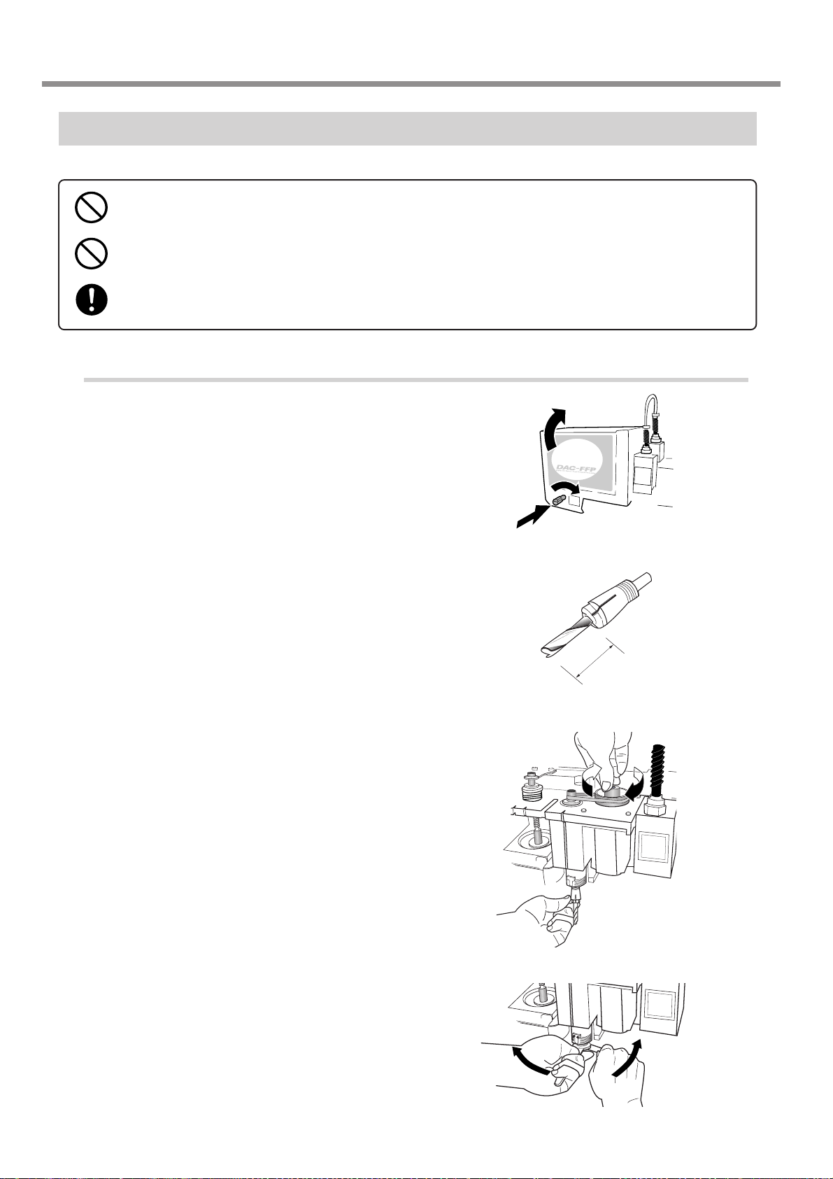
3-5. Cutter Installation Method 4 (End Mill)
While installing the cutter, do not allow the operation panel to be touched inadvertently. When using the
operation panel, keep hands away from moving areas of the machine. Unintended operation of the ma-
chine may lead to danger of becoming caught.
Do not touch the tip of the cutter. Doing so may result in injury.
Securely fasten the cutter and workpiece in place. Otherwise they may come loose during cutting, resulting
in injury.
Installing an End Mill
1. Installing the Collet and End Mill
Open the spindle cover.
1
Insert the end mill into the optionally available
2
end-mill collet.
Insert the end mill and collet from below. While
3
gently holding the collet in place, turn the
spindle by hand until it is finger-tight.
3.
2.
1.
20 to 25 mm (3/4 to 1 in.)
Use the included wrench to tighten the collet.
4
The correct tightening torque is 32 kgf-cm.
52
Chapter 3 - Preparations
Page 57

2. Menu Settings
Be sure to set [AUTO Z CONTROL] to OFF.
Fully tighten the lock nut.
5
Use the menus to set [AUTO Z CONTROL] to OFF.
6
3-5. Cutter Installation Method 4 (End Mill)
(1) Press several times to display the screen shown at right.
(2) Press
(3) Press
(4) Press to move the blinking cursor to [OFF], then press .
Use the menu to set [REVOLUTION] to ON.
7
(1) Press several times to display the screen shown at right.
(2) Press
(3) Press to move the blinking cursor to [ON], then press .
to move the blinking cursor to [OTHERS], then press .
several times to display the screen shown at right.
to move the blinking cursor to [OTHERS], then press .
I/O OTHERS
TEACHING SELF
AUTO Z CONTROL
ON <OFF>
I/O OTHERS
TEACHING SELF
REVOLUTION
<ON> OFF
Press several times to return to the top screen.
8
X 0 Y 0
Z 0 8000RPM
Chapter 3 - Preparations
53
Page 58
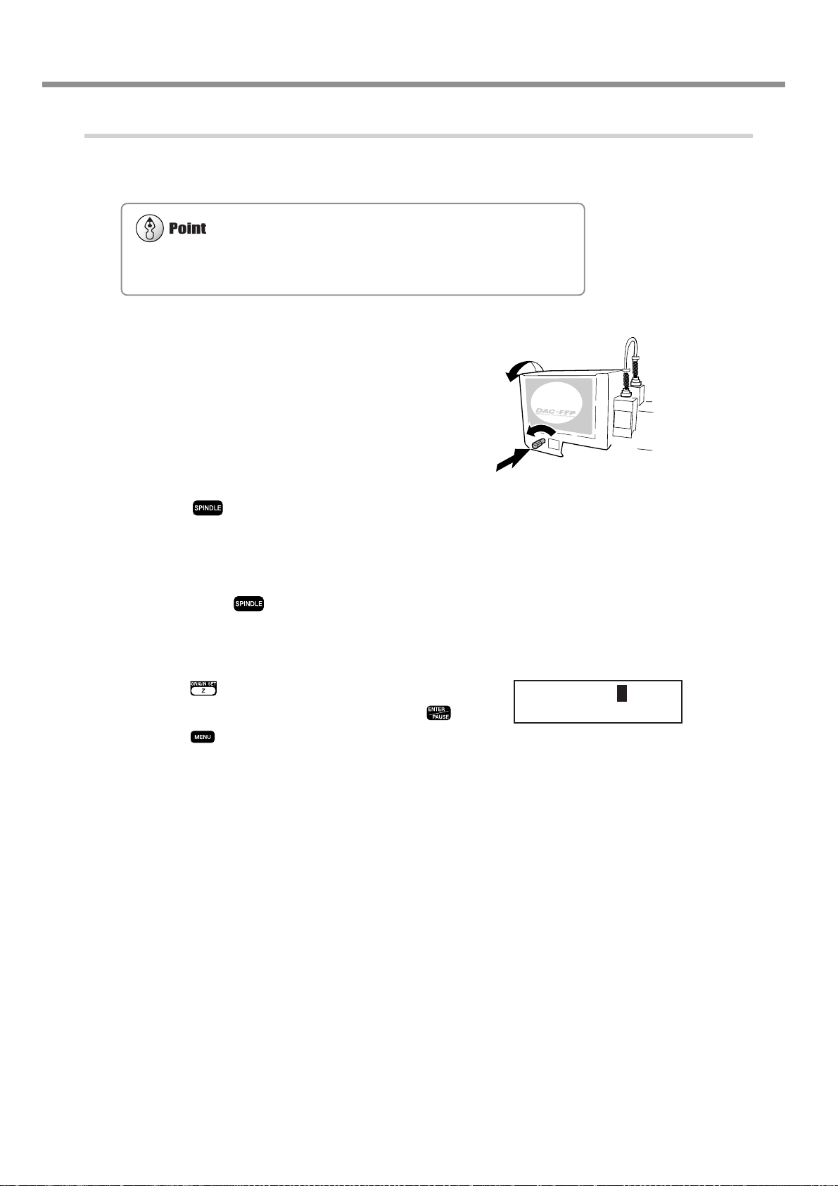
3-5. Cutter Installation Method 4 (End Mill)
For information on how to load material
☞ See p.55 "Loading Material and Setting the Reference Point for Cutting"
3. Aligning the Cutter
Load a workpiece and move the end mill to the
9
top surface of the material.
10
11
12
13
Close the spindle cover.
Hold down for 0.5 seconds or longer.
The spindle rotates.
Lower the spindle a little at a time, and stop it
when it is just barely cutting the surface of the
workpiece. Press to stop the spindle.
Use the menus to set the height reference point (Z0).
(1) Press .
(2) Make sure the blinking cursor is at [Z0], then press
(3) Press to return to the top screen.
1.
3.
2.
SET Z1 Z0 Z2
.
SURFACE < 0 >
54
Chapter 3 - Preparations
Page 59

3-6. Loading Material and Setting the Reference Point for Cutting
Securely fasten the cutter and workpiece in place. Otherwise they may come loose during cutting, resulting
in injury.
When you're using a clamp or other jig, give sufficient thought to positioning so that the tool and spindle
unit do not collide during operation. The tool may break and fly off, resulting in injury. Breakdown may also
result.
Loading Material
You use the following method to load a workpiece. The table has T slots, and you can also install other jigs. There is also
a guide for positioning on the side of the table.
Clamp
This is included with the machine. Pass the bolt through a T slot and tighten the nut.
Adhesive sheet
This method uses an optionally available adhesive sheet for attachment. This is suited to tasks that involve a relatively
light load, such as plate engraving.
Center vise
This method uses an optionally available center vise for securing in place.
Chapter 3 - Preparations
55
Page 60

3-6. Loading Material and Setting the Reference Point for Cutting
The Loaded Position of the Workpiece
You may load the workpiece anywhere on the table.
Butting the workpiece against the guide is a handy way to ensure that the workpiece is always loaded at the same
position. Adjust the height of the guide to match the thickness of the workpiece.
Setting the Reference Point for the Cutting Position
This machine lets you freely change the cutting position. The place where you should set the reference point for the
cutting position changes according to how the data was created with the program. Always loading material at the same
location and keeping the reference point for the cutting position on the machine fixed may make positioning easier.
The reference point for cutting is the location where the X- and Y-axis coordinates are both zero (that is, the X- and Y-axis
origin point). This is also called the home position. This is initially set at the front left of the table.
Setting the Home Position
Move the spindle to the location you want to be
1
the reference point for the cutting position.
Press , then press .
2
Press to return to the top screen.
3
SET HOME POS
< 0 > < 0 >
X 0 Y 0
Z 0 8000RPM
56
Chapter 3 - Preparations
Page 61

4. Performing Cutting
Using a Computer
This chapter describes how to perform cutting using a computer. It
explains important notes when sending commands from a computer ,
differences among programs in how to make the setting for the cutting parameters, and the procedures for installing and setting up the
included programs.
57
Page 62

4-1. Procedures for Performing Cutting Using a Computer
For more information on how to set the cutting parameters
☞ See p.59 "Setting the Cutting Parameters"
Before you send cutting commands from a computer, you first need to set the cutting parameters. You make the settings
for cutting-in depth, feed rate, spindle speed, and other values to match the cutter and the workpiece. The method you use
to make the settings differs from one program to another.
This machine starts operating immediately when it receives commands from a computer . However , you should close the
spindle cover before sending commands. For safety, the machine does not operate while the cover is open.
58
Chapter 4 - Performing Cutting Using a Computer
Page 63

4-2. Setting the Cutting Parameters
Types of Cutting Parameters
You can make the settings for the following five cutting parameters on this machine.
• Spindle rotating speed
• Feed rate in the X- and Y-axis directions
• Feed rate in the Z-axis direction
• Cutting-in depth (Z1)
• Amount of cut-out during feed while raised (Z2)
You can make the settings for these either on the machine by using the menus, or by using the program. When you make
a setting both on the machine and in the program, the program's setting is the one that takes effect. This means there is no
point in making the same setting both on the machine and with the program.
Differences in Setting Items Between Programs
Programs may differ in how many of the five cutting parameters they let you set. Some programs may allow you to make
the settings for all five, but with others it is necessary to make some of the settings on the machine. For information about
what settings must be made on the machine, refer to the program's documentation.
Also, with some programs for solid, three-dimensional cutting, flat parameters such as the cutting-in depth and the cutout amount have no meaning.
Cutting
Parameters
Spindle rotating speed
X- and Y-axis feed rate
Z-axis feed rate
Cutting-in depth
Cut-out amount
* This setting is generally not required when using the nose unit or a diamond scraper.
☞ See p.41 "Cutting Parameters When Using the Nose Unit"
☞ See p.50 "Cutting Parameters for the Diamond Scraper"
Dr.Engrave
(2.5D driver)
Program
Program
Program
Program *
Program *
3D Engrave
Program
Program
Program
Not valid
Not valid
Example of another
program
Machine
Program
Machine
Machine *
Machine *
Chapter 4 - Performing Cutting Using a Computer
59
Page 64

4-2. Setting the Cutting Parameters
You can also change the spindle speed while at the top screen, by turning the dial. Note, however, that when the machine is turned off, the spindle speed returns to the value you set using the
procedure described above.
You can change the feed rate while cutting is in progress. Follow the steps below to make the change.
(1) While cutting is in progress, press
. Cutting pauses.
(2) Press
. The screen shown in step 2 described above appears. Make the appropriate setting.
(3) Press
, then press . Cutting resumes at the new feed rate.
Making the Settings on the Machine
Spindle Rotating Speed
Setting the Spindle Rotating Speed
Press several times to display the screen
1
shown at right.
Use to set the spindle speed, then
2
press .
Feed Rate
Setting the Feed Rate
Press several times to display the screen
1
shown at right.
Press to move the blinking cursor
2
to [XY-SPEED] or [Z-SPEED].
[XY-SPEED] sets the X- and Y-axis feed rate, and [ZSPEED] sets the Z-axis feed rate.
SPINDLE RPM
< 8000RPM >
XY-SPEED Z-SPEED
< 2mms > < 2mms >
Use to set the feed rate, then press
3
60
Chapter 4 - Performing Cutting Using a Computer
.
Page 65

Cutting-in Depth and Cut-out Amount
Important Notes on Setting the Cutting-in Depth
The cutting-in depth is a setting that indicates the amount of lowering from the Z-axis reference point (the Z0 position). If
the Z0 position changes, then the cutting-in position (the Z1 position) also changes by a corresponding amount.
The Z1 position cannot be set above the Z0 position. When the spindle is above the Z0 position, the value displayed is
[------], indicating that the setting cannot be made at this position.
Unit of Measurement for the Numerical Values
The measurement unit for the displayed values is 0.01 mm. When [-20] is displayed, for example, the cutting-in amount is
0.2 mm.
Important Notes on Setting the Cut-out Amount
The cut-out amount is a setting that indicates the amount of rise from the Z-axis reference point (the Z0 position). If the Z0
position changes, then the cut-out position (the Z2 position) also changes by a corresponding amount.
The Z2 position cannot be set below the Z0 position. When the spindle is below the Z0 position, the value displayed is
[------], indicating that the setting cannot be made at this position. This means that you cannot set a cut-out amount when the
Z0 position is at the highest point on the Z axis.
Unit of Measurement for the Numerical Values
The measurement unit for the displayed values is 0.01 mm. When [100] is displayed, for example, the cut-out amount is 1
mm.
Setting the Cutting-in Depth
4-2. Setting the Cutting Parameters
Press . Press to move the blinking cursor to
1
[Z1].
Use to set the cutting-in amount. If the value is
2
[------], then hold down until it changes to a numerical
value.
At this time the spindle moves up and down and the position when cutting-in is performed (the Z1 position) is displayed. You can set the cutting-in depth as you verify the actual Z1 position.
Press .
3
SET Z1 Z0 Z2
DOWN < 0 >
Setting the Cut-out Amount
Press . Press to move the blinking cursor to
1
[Z2].
Use to set the cut-out amount. If the value is
2
[------], then hold down until it changes to a numerical
value.
At this time the spindle moves up and down and the position of cut-out
(the Z2 position) is displayed. You can set the cut-out amount as you
verify the actual Z2 position.
Press .
3
SET Z1 Z0 Z2
UP < 0 >
Chapter 4 - Performing Cutting Using a Computer
61
Page 66

4-3. Installation and Overview of the Included Software
Software Included with the Machine
The included Roland Software Package CD-ROM contains the following programs. Install and set them up as required.
Dr.Engrave
3D Engrave
MODELA Player
2.5D driver
Virtual MODELA
This document does not explain how to use these programs. For information about program operation, refer to other
documentation such as the manuals in electronic format found on the CD-ROM.
☞ See p.4 "Documentation Included with the Machine"
This program is for flat engraving of nameplates and the like. It can use any TrueType fonts
registered with Windows. It also comes with its own stroke fonts. You can even import
images and engrave items such as logos. There is even a feature that lets you import data
from a list of names and engrave nameplates one after another.
This program is for designing and engraving reliefs (raised engravings). This lets you easily
add thickness to text, shapes, and imported images, and create three-dimensional reliefs.
This program is for freely cutting three-dimensional shapes. You cannot perform designing
using this program alone. MODELA 3D Design and MODELA 3D Text are included.
This is a Windows-based driver required for sending data from a computer to the machine.
Be sure to install it when you are using any of the programs just described.
This program is for performing simulations before you actually carry out cutting using 3D
Engrave or MODELA Player. It lets you verify the finished results for shapes, the time
required for cutting, and other factors. This can help reduce loss in terms of material and
time.
Installation and Setup
System Requirements
Operating system
Computer
Drive
Monitor
Memory (RAM)
Free hard-disk space
required for installation
Interface
Windows 95/98/Me/NT4.0/2000/XP
Computer running Windows (Pentium processor or better recommended)
CD-ROM drive
Windows-compatible monitor capable of displaying 256 colors or more
32 MB or more recommended
32 MB
Printer port or COM port
62
Chapter 4 - Performing Cutting Using a Computer
Page 67

Installation and Setup
Installation and Setup
Switch on the computer and start Windows.
1
If you are installing under Windows NT 4.0/
2000/XP, log on to Windows as a member of
the "Administrators" or "Power Users" group.
Place the CD from the Roland Software Pack-
2
age in the CD-ROM drive.
The Setup menu appears automatically.
Click the in [Click here], then choose [EGX-
3
600] or [EGX-400]. Click [Install].
If there are programs you don't want to install, then clear
their check boxes before you click [Install].
4-3. Installation and Overview of the Included Software
EGX-600
The Setup program starts. Follow the messages
4
to carry out setup and finish setting up the program.
When the setup for one program finishes, the setup for
the next program starts. In the interval until the next setup
starts, a dialog box showing the progress of processing
is displayed.
If the following screen appears while installing
5
the driver, click the drop-down arrow and
choose the port for the cable connected to the
computer.
When using a serial cable : [COM1:] or [COM2:]
When using a printer cable : [LPT1:]
The driver settings appear. When you make the
6
settings for the communication parameters of
this machine, make the parameters match the
values displayed here.
Click [Close] to finish installing the driver.
(Continued on the next page)
EGX-600 Driver Install
Settings:[EGX-600]
Chapter 4 - Performing Cutting Using a Computer
63
Page 68

4-3. Installation and Overview of the Included Software
When all installation finishes, the screen shown
7
at right appears. Click [Close].
After returning to the menu screen for installa-
8
tion, click .
Remove the CD-ROM from the CD-ROM drive.
9
64
Chapter 4 - Performing Cutting Using a Computer
Page 69

4-4. Executing Cutting Data Saved on a Memory Card
☞ See p.31 "Memory-card Writers You Can Use"
Working with Cutting Data on a Memory Card
You can take cutting commands sent from the computer and save them as data. Y ou can then save this data on a memory
card and import it into the machine. This means that you can receive data with a memory card in exactly the same way as
receiving commands from a computer via a connector cable.
This lets you distribute cutting data using just a memory card, making it possible to operate a number of machines in
locations where no computer is available.
Requirements for Saving Cutting Data
To save cutting data on a memory card, you use a commercially available memory-card writer.
Chapter 4 - Performing Cutting Using a Computer
65
Page 70

4-4. Executing Cutting Data Saved on a Memory Card
Use a file name of eight characters or fewer, with a file extension of three characters or fewer. File names that do not meet
these criteria are not displayed correctly on the machine.
Do not try to save in a subdirectory. This machine does not recognize subdirectories.
Detailed Information About File Names
☞ See p.70 "Important Notes When Saving Cutting Data"
Saving Cutting Data
First, connect the memory-card writer to your computer running Windows. For information about how to make the
connections, refer to the documentation for the memory-card writer.
This section describes how to use the included programs to save data on a memory card.
Saving from Dr. Engrave
T o save cutting data output from the included Dr . Engrave engraving program on a memory card, follow the steps below.
Saving from Dr. Engrave
Load a memory card into the memory-card
1
writer.
Start Dr. Engrave, go to the [File] menu, and
2
click [Print Setup]. Choose the EGX-400 or the
EGX-600, then click [OK].
Create the design to engrave, then go to the
3
[File] menu and click [Print].
The [Print] dialog box appears.
Select the [Print to File] check box, then click
4
[OK].
The [Print to File] dialog box appears.
For [Save in], select the memory-card drive.
5
Type in a file name, then click [Save].
The cutting data is saved on the memory card.
66
Chapter 4 - Performing Cutting Using a Computer
Page 71

4-4. Executing Cutting Data Saved on a Memory Card
Saving from Another Program
For a program such as the included 3D Engrave, follow the steps below. You can also use this method with other programs (as long as the other program uses a driver for Windows).
Saving from Another Program
If you are using Windows NT 4.0/2000/XP, log
1
on to Windows as a member of the "Administrators" or "Power Users" group.
Load a memory card into the memory-card
2
writer.
Open [My Computer]. Note the drive name of
3
the memory card.
In the example shown in the figure, the drive name is
"E:."
For Windows 95/98/Me/NT 4.0/2000:
4
Click [Start], then [Settings]. Then click [Printers].
For Windows XP:
Click [Start], then click [Control Panel]. Click [Printers
and Other Hardwares], then click [Printers and Faxes].
Right-click the icon for the EGX-600 or EGX-
5
400 driver, then click [Properties].
(Continued on the next page.)
Chapter 4 - Performing Cutting Using a Computer
67
Page 72

4-4. Executing Cutting Data Saved on a Memory Card
Use a file name of eight characters or fewer, with a file extension of three characters or fewer. File names that do not meet
these criteria are not displayed correctly on the machine.
Do not try to save in a subdirectory. This machine does not recognize subdirectories.
Detailed Information About File Names
☞ See p.70 "Important Notes When Saving Cutting Data"
For Windows 95/98/Me:
6
Click the [Details] tab.
For Windows NT 4.0/2000/XP:
Click the [Ports] tab.
Make a note of what is selected for [Print to
7
the following port] or [Port] (this may be
[LPT1:], [COM1:], or the like). Next, change
this to [FILE:]. Click [OK].
* Windows 95/98/Me
Start the program and select the EGX-600 or
8
the EGX-400 as the output destination. Create
the design to cut, then perform output.
The [Print to File] dialog box appears.
* Windows NT4.0/2000/XP
9
10
11
For [Output file name], type in the memory-card
drive name you noted in step 3, followed by a
backslash (\) and a file name.
For example, if the drive name is "E:" and you want to
use "CUTDATA.PRN" as the file name (with the file
extension), then type in "E:\CUTDATA.PRN" here.
Click [OK].
The cutting data is saved on the memory card.
Follow steps 4 to 7 to restore the port to the
setting you noted down in step 7.
68
Chapter 4 - Performing Cutting Using a Computer
Page 73

4-4. Executing Cutting Data Saved on a Memory Card
There may be a slight delay of several seconds to several dozen seconds until
the file-selection screen appears. During this time, do not try to remove the
memory card or switch off the power.
The execution of cutting data is exactly like operation when commands are received from a computer. Coordinate values are
displayed during execution, and the pause menu is also available. Make the settings for the home position, the Z0 position, and
cutting parameters using the same procedures as for when receiving commands from a computer.
Importing and Executing Memory-card Data
To operate the machine using cutting data saved on a memory card, follow the steps below.
Importing and Executing Data
Insert the memory card on which cutting data
1
is saved into the memory-card slot.
Press several times until the screen
2
shown at right appears. Make sure the blinking
cursor is at [RUN], then press .
The screen for selecting the file appears.
Turn the dial to display the file name for the
3
cutting data that you want to import.
Press .
The cutting data is imported and operation starts.
RUN
Now Processing...
Select File
OUTPUT03.PRN
Chapter 4 - Performing Cutting Using a Computer
69
Page 74

4-4. Executing Cutting Data Saved on a Memory Card
Important Notes When Saving Cutting Data
Valid Characters for File Names
Use the following characters for the file names you assign when saving cutting data.
• Letters: A through Z
• Numerals: 0 through 9
• Special characters: $, &, #, %, -, _, ~ (the space character cannot be used)
Also, use a file name of eight characters or fewer, with a file extension of three characters or fewer.
Using a file name that does not meet these criteria may result in character corruption or the file name failing to be
displayed on the machine.
A Note on Creating New Folders
The machine does not display files saved in folders (subdirectories) created on a memory card. Cutting data for use with
this machine must be saved in the root directory.
The Number of Files That Can Be Saved
This machine can handle up to 512 files saved in the root directory. It is possible to save more than 512 files in a
subdirectory, but the machine cannot use them.
Note that the actual number of files that can be saved depends on the available space on the memory card.
Deleting Cutting Data
T o delete cutting data, load the memory card into a memory-card writer and drag the file or files you want to delete to the
Recycle Bin in Windows.
70
Chapter 4 - Performing Cutting Using a Computer
Page 75

5. The Teaching Feature
This chapter describes how to use the teaching feature. It provides
detailed explanations of how to create and save sequences, how to
execute the sequences you create, the commands you use, and more.
71
Page 76

5-1. Overview of the Teaching Feature
What Is the Teaching Feature?
This feature lets you teach operation instructions directly to the machine without using a computer. You use the operation
panel to enter the operation instructions. Each operation instruction that you enter is called a "command," and a collected
set of commands is called a "sequence." You can save created sequences in the built-in memory or on a memory card.
Once you have made a sequence, you can make the machine move in the specified way whenever you like.
The teaching feature lets you do things like those described below.
Basic Operations Possible with Commands
• Linear movement to specified coordinates (simultaneous three-axis movement is possible)
• Arc movement
• Starting and stopping spindle rotation
• External-equipment control using the expansion connector 2 (input-port monitoring and output-port control)
Positioning Functions
• Registering an optional origin and calling it up in a sequence
• Setting an I level and an R level
Functions for Creating Sequences
• Specifying labels
• Executing conditional branches in programs using jump commands
• Subroutine execution through call commands
Important Notes When Using the Nose Unit
When you use the teaching feature to operate the machine, the [AUTO Z CONTROL] function is disabled. Please note
that the cutting-in depth and the amount of cut-out are not set automatically even when you use a nose unit or perform
scribing using a diamond scraper. The cutting-in depth and the amount of cut-out must be specified entirely within a
sequence.
72
Chapter 5 - The Teaching Feature
Page 77

5-2. Basic Steps for Creating and Executing a Sequence
In this section you learn the basics of using the teaching feature through a explanation of the steps for creating and
running a very simple sequence. For details about the functions of each command and about other functions and features,
refer to later sections.
Step 1 Decide on the Mode of Operation and the Origin Points
First decide what movement you want to perform. In this example we'll try cutting a quadrilateral, then moving the
spindle out of the way.
The important thing here is to decide on the origin points for the X, Y, and Z axes ahead of time. The cutting location
changes according to the home position and the Z0 position. It may not be possible to perform the same cutting every
time unless you decide on definite origin points. The direction of the approach to the workpiece is also important. You
must move to the start point while avoiding the jig or the like used to secure the workpiece in place. That is, you need to
consider in advance what kind of jig is to be used to secure the workpiece.
Home position : Front left edge of the table (machine origin point)
Z0 position : Workpiece surface
Cutting-in depth : 0.2 mm
X- and Y-axis feed rate : 15 mm/s
Z-axis feed rate : 2 mm/s
Spindle speed : 10,000 rpm
Start
Machine origin point
(2000, 4000)
Finish
: Specified feed rate
: Highest feed rate
50 mm
Home position
20 mm
1.2 mm
10 mm
(2000, 1000)
(7000, 4000)
30 mm
(7000, 1000)
Chapter 5 - The Teaching Feature
73
Page 78
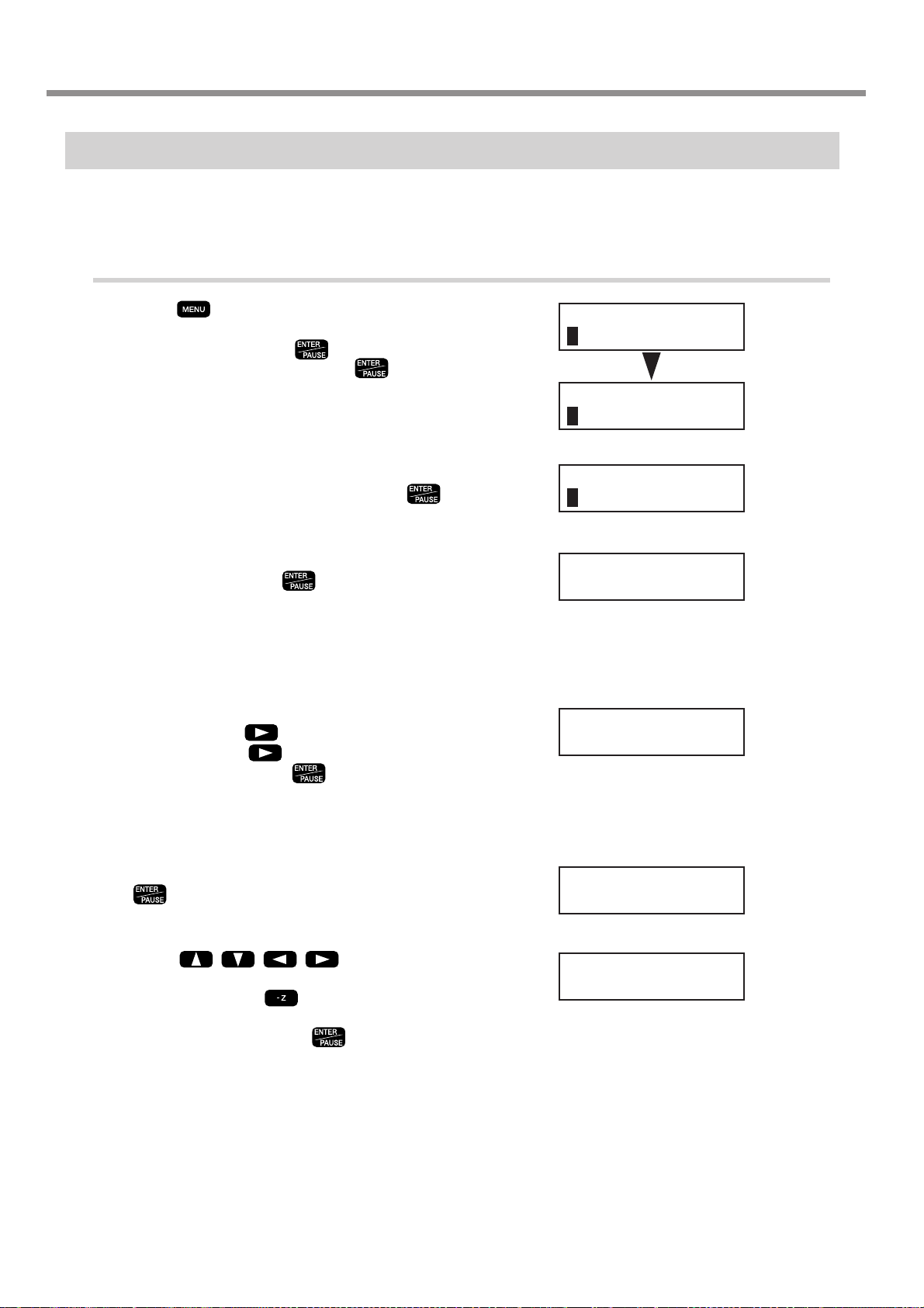
5-2. Basic Steps for Creating and Executing a Sequence
Step 2 Create the Sequence
Now let's actually create the sequence. First carry out operations without loading a workpiece. We'll assume that the Z0
position is set at the surface of the workpiece.
Example of Sequence Creation
Press several times to display the screen
1
shown at right, then move the blinking cursor
to [TEACHING]. Press . Move the blinking cursor to [EDIT], then press .
Specify creation of a new sequence. Make sure
2
the blinking cursor is at [Y es], then press .
The sequence editing screen appears.
Turn the dial to make the display change to [1
3
MOVE-LIMIT]. Press .
You have now finished entering the commands to move
the spindle to the machine origin point at the highest speed
as the first step. When you finish making the entries for
the first step, the display changes to the input screen for
the second step.
Turn the dial to make the display change to [10
4
SP OFF]. Press , then turn the dial to display [ON]. Press again, then turn the dial
to display [100]. Press .
Now you have entered the commands for rotating the
spindle. [100] means rotation at 10,000 rpm. Now the
input screen for the third step appears.
I/O OTHERS
TEACHING SELF
RUN DELETE
EDIT SETTING
Edit New File ?
Yes No
1:
< 1 MOVE-LIMIT >
2:
< 10 SP ON 100 >
74
Turn the dial to display [3 MOVE-ZM]. Press
5
6
Chapter 5 - The Teaching Feature
.
The screen changes to the coordinate view.
Press to move the X
and Y axes to the first cutting point (X 2000, Y
1000). Next, press to move the Z axis to
a location 1 millimeter from the surface of the
workpiece (Z 100). Press .
Check the displayed coordinates as you perform movement. Now you have entered the commands for moving
the X and Y axes to the specified position, then lowering
the Z axis at the highest speed to a position close to the
surface of the workpiece. Next, the input screen for the
fourth step appears.
3:
3 MOVE-ZM
X 2000 Y 1000
Z 100 8000RPM
Page 79
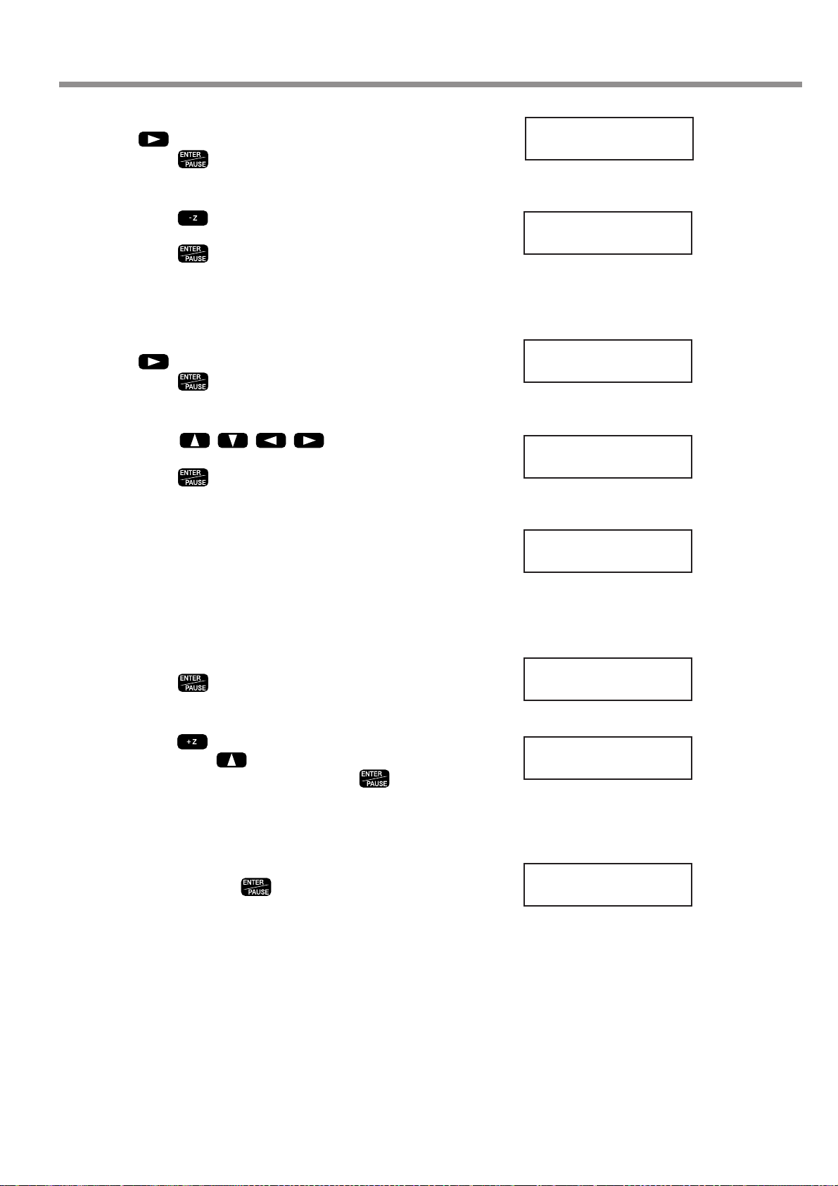
5-2. Basic Steps for Creating and Executing a Sequence
7
8
9
10
Turn the dial to display [8 CUT-3 2]. Press
, then turn the dial to display [3].
Press .
The screen changes to the coordinate view.
Press to move the Z axis to where it cuts
into the workpiece by 0.2 mm (Z -20).
Press .
Now you have entered the commands for cutting into the
workpiece at a feed rate of 3 mm/s. Next, the input screen
for the fifth step appears.
Turn the dial to display [8 CUT-3 2]. Press
, then turn the dial to display [15].
Press .
The screen changes to the coordinate view.
Press to move the X
and Y axes to the (X 7000, Y 1000) point.
Press .
Next, the input screen for the sixth step appears.
4:
8 CUT-3 3
X 2000 Y 1000
Z -20 8000RPM
5:
8 CUT-3 15
X 7000 Y 1000
Z -20 8000RPM
11
12
13
14
In the same way as for steps 9 and 10, input
the commands to move to (X 7000, Y 4000), to
(X 2000, Y 4000), and to (X 2000, Y 1000).
Now you have entered the commands for cutting a quadrilateral at a feed rate of 15 mm/s. Next, the input screen
for the ninth step appears.
Turn the dial to display [3 MOVE-ZM].
Press .
The screen changes to the coordinate view.
Press to raise the Z axis to its upper limit.
Then press to move the Y axis all the
way to the back of the table. Press .
Now you have entered the commands for raising the Z
axis to the upper limit, then moving the spindle out of
the way. Next, the input screen for the tenth step appears.
Turn the dial to make the display change to [10
SP OFF]. Press .
Now you have entered the command for stopping rotation of the spindle. The input screen for the eleventh step
then appears, but the procedure is finished. The final step
must always be [22 FINISH].
6:
8 CUT-3 15
9:
3 MOVE-ZM
X 2000 Y 40700
Z 4128 8000RPM
10:
< 10 SP OFF >
Chapter 5 - The Teaching Feature
75
Page 80

5-2. Basic Steps for Creating and Executing a Sequence
The [Int.] to the left of the file name means the sequence
has been saved in the built-in memory. Sequences saved
on a memory card are displayed with [Ext.].
Step 3 Save the Sequence
Next, you save the sequence you have created.
Procedure for Saving a Sequence
Press and hold for a short while (1 sec-
1
ond or longer). Press .
This quits the sequence editing screen and displays the
screen for saving a sequence.
Assign a file name. Press to move the
2
blinking cursor. Turn the dial to select a character, then press to move to the next
character.
You can repeat this to assign a file name of up to eight
characters.
Press .
3
The sequence is saved and the machine returns to the
teaching menu.
Save Sequence ?
Yes No Cancel
Select File
Int. TEST
Step 4 Execute the Sequence
Let's try executing the sequence you created. First, to verify the operation, let's execute it without installing a cutter or
loading a workpiece.
Procedure for Executing a Sequence
Press several times to display the screen
1
shown at right, then move the blinking cursor
to [TEACHING]. Press . Move the blinking cursor to [RUN], then press .
Call up the saved sequence. Turn the dial to
2
select it. Let's try selecting the [TEST] you created earlier.
Press .
3
Operation starts. The screen successively displays the
commands being executing.
I/O OTHERS
TEACHING SELF
RUN DELETE
EDIT SETTING
Select File
Int. TEST
76
Chapter 5 - The Teaching Feature
Page 81

5-3. Correcting a Sequence
If You Make a Mistake in Input
You can go back to a previous step and revise it at any time if you discover an input error when creating a sequence. Y ou
can also insert steps and delete single steps.
Correcting a Previous Step
Press to move the blinking cursor to the
1
step number.
Turn the dial to display the step you want to
2
revise.
Press to move the blinking cursor to the
3
line below. Follow the same procedure as for
entering new commands. Y ou can also change
the values of commands. When you've finished
making the revisions, press .
Press to move the blinking cursor to the
4
step number. Turn the dial to move to the final
step. Press to move the blinking cursor
to the line below, then resume normal input operations.
Inserting a Step
11:
< 22 FINISH >
5:
< 8 CUT-3 78 >
5:
8 CUT-3 15
Change Change
a command a value
11:
< 22 FINISH >
Press to move the blinking cursor to the
1
step number.
Turn the dial to move to the location where you
2
want to insert.
The new step is inserted just before the displayed step.
Press to move the blinking cursor to the
3
line below. Turn the dial to display [INSERT
NEW STEP]. Press .
The new step is inserted. Turn the dial to select the command you want. This is initially set to the [23 DO NOTHING] command.
11:
< 22 FINISH >
9:
< 10 SP OFF >
9:
INSERT NEW STEP
Chapter 5 - The Teaching Feature
77
Page 82

5-3. Correcting a Sequence
You cannot delete the last step. Every sequence must have at least one [FINISH] command.
Deleting a Step
Press to move the blinking cursor to the
1
step number.
Turn the dial to display the step you want to
2
delete.
Press to move the blinking cursor to the
3
line below. Turn the dial to display [DELETE
THIS STEP]. Press .
The step is deleted.
11:
< 22 FINISH >
9:
< 15 BREAK >
9:
DELETE THIS STEP
78
Chapter 5 - The Teaching Feature
Page 83

Revising a Saved Sequence
The [Int.] to the left of the file name means the sequence
has been saved in the built-in memory. Sequences saved
on a memory card are displayed with [Ext.].
You can call up a saved sequence, revise it, and save it again.
Calling Up and Revising a Sequence
5-3. Correcting a Sequence
Press several times to display the screen
1
shown at right, then move the blinking cursor
to [TEACHING]. Press . Move the blinking cursor to [EDIT], then press .
Press to move the blinking cursor
2
to [No]. Press .
Turn the dial to choose the sequence you want
3
to revise. Press .
The sequence editing screen appears.
I/O OTHERS
TEACHING SELF
RUN DELETE
EDIT SETTING
Edit New File ?
Yes No
Select File
Int. TEST
Use the same procedure described earlier in
4
"If You Make a Mistake in Input" to revise the
sequence.
Press and hold for a short while (1 sec-
5
ond or longer), then press .
Turn the dial to choose the file to overwrite, then
6
press .
Make sure that it's okay to overwrite, then
7
press .
If you want to cancel the save and overwrite operation,
use
then press
to move the blinking cursor to [No],
.
Save Sequence ?
Yes No Cancel
Select File
Int. TEST
OverWrite File ?
Yes No
Chapter 5 - The Teaching Feature
79
Page 84

5-4. Detailed Description of the Sequence Editing Screen
This section describes the button operations of the [EDIT] menu in detail, and also explains other practical functions.
Screen Layout and Button Operations
Basic Layout of the Sequence Editing Screen
Step number
This shows the number of the step. You can input
up to 1,000 steps per sequence.
2: LABEL
< 10 SP ON 200 >
Command
This is the instruction for operation. When you select a command, the angled brackets ("< >") disappear. Pressing
makes the angled brackets appear.
to confirm it and finish input
Label name
You can assign names to steps as required. These
names are called "labels." Labels are used with commands such as [JUMP] and [CALL].
Value
A command may have one or more values. There
are also commands that have separate, detailed
screens that let you specify even more values.
Main Functions of the Control Buttons
These are some typical functions of the buttons you use for operation. Depending on the command you select, the buttons
may also have special functions. For more information about the button operations for each corresponding, see "List of
Commands" on p.87.
Dial
These move the blinking cursor.
This is used to increase or decrease the value or to select the command at the location of
the blinking cursor. Turning the dial while holding down increases or decreases
the value by 100 units at a time.
Pressing this while a step number is displayed changes the screen to the coordinate
view . While at this screen, you can move the spindle head and rotate the spindle with the
same button operations as when you're at the top screen. You also use this at times such
as when you want to verify the position of the spindle head while you're creating a
sequence.
Also, holding it down for a short while (one second or longer) ends sequence creation.
Pressing this at any other screen cancels input.
This enables what you have input. You also use it to go to a detailed screen, depending
on the command.
80
Chapter 5 - The Teaching Feature
Page 85

5-4. Detailed Description of the Sequence Editing Screen
Setting a Label
A label is used to specify the jump destination for [JUMP], [J], [CALL], and [C] commands. When you use any of these
commands, you must be sure to assign a label. If you try to save a sequence without assigning a required label, the
machine displays [INPUT LABEL NAME], then returns to the sequence editing screen.
Setting a Label
At the sequence editing screen, display the step
1
where you want to assign a label.
Use to move the blinking cursor to the
2
location shown in the figure.
Turn the dial to select a character, then press
3
4
to move to the next character. You can
assign a label name of up to five characters by
repeating this operation.
Press .
2:
< 10 SP ON 200 >
2:
< 10 SP ON 200 >
2: LABEL
10 SP ON 200
2: LABEL
< 10 SP ON 200 >
Chapter 5 - The Teaching Feature
81
Page 86

5-5. Detailed Information on Saving a Sequence
There may be a slight delay of several seconds to several dozen seconds until the fileselection screen appears. During this time, do not try to remove the memory card or
switch off the power.
Destinations for Saving Sequences
You can save sequences either in the machine's built-in memory or on a memory card. Y ou can save up to ten sequences
in the built-in memory . The number you can save on a memory card varies according to the card's capacity. Note that the
maximum is 512.
Specify either the built-in memory or a memory card for saving or calling up a file. A file displayed with [Int.] is in the
machine's built-in memory, and one displayed with [Ext.] is on a memory card.
When saving a file, if you want to save it as a new file with a different name, select [new file], then enter the file name.
If you want to save it by overwriting the existing file, select the name of the existing file. When you do this, a prompt is
displayed to confirm that you want to overwrite the file.
Select File
Int. new file Int. new file
Int.
Built-in memory
...........
File name 1
......................
Int.
File name 2
..................................
○○○○
Saving as a new file
Saving by overwriting
the existing file
Memory card
OverWrite File ?
Yes No
Ext. new file
File name 1
...............
A prompt to confirm overwriting is displayed.
Ext.
......................
Ext.
File name 2
.................................
Dial
Saving as a new file
Saving by overwriting
the existing file
82
Chapter 5 - The Teaching Feature
Now Processing...
Page 87

5-5. Detailed Information on Saving a Sequence
Backing Up a Sequence
You can back up sequence saved in the machine's built-in memory to a memory card. Back up important data to a
memory card.
Backing Up from the Built-in Memory to a Memory Card
Insert a memory card into the machine's
1
memory-card slot.
Press several times to display the screen
2
shown at right, then move the blinking cursor
to [TEACHING]. Press . Move the blinking cursor to [EDIT], then press .
Press to move the blinking cursor to [No].
3
Press .
Turn the dial to select a sequence saved in the
4
built-in memory. Press .
The sequence editing screen appears.
Press and hold for a short while (1 sec-
5
ond or longer), then press . Turn the dial
to select the memory card as the destination
for saving. Also, assign a file name here.
I/O OTHERS
TEACHING SELF
RUN DELETE
EDIT SETTING
Edit New File ?
Yes No
Select File
Int. TEST
Select File
Ext. new file
Select File
Ext. BACKUP
Press .
6
A backup copy of the sequence is saved on the memory
card.
Chapter 5 - The Teaching Feature
83
Page 88

5-5. Detailed Information on Saving a Sequence
Deleting a Sequence
You can delete saved sequences.
Deleting a Sequence
Press several times to display the screen
1
shown at right, then move the blinking cursor
to [TEACHING]. Press . Move the blinking cursor to [DELETE], then press .
I/O OTHERS
TEACHING SELF
RUN DELETE
EDIT SETTING
Turn the dial to choose the sequence you want
2
to delete. Press .
Move the blinking cursor to [Yes], then
3
press .
The sequence you selected is deleted.
Select File
Int. TEST
Are Y ou Sure?
Yes No
84
Chapter 5 - The Teaching Feature
Page 89

5-6. Coordinate Systems Used with the Teaching Feature
About Workpiece Coordinates
☞ See p.102 "Coordinate Systems and Origin Points"
You can check the coordinate values of the registered
optional origins at this time by pressing
instead
of
. To go back to the original screen, press .
When nothing has been registered, the display shows
(X 0, Y 0, Z 0). That is, it is the same as the location of
the workpiece origin point.
Cutting Positions Used with the Teaching Feature
The origin points used with the teaching feature are basically the same as the ones used when you perform cutting with
a computer. That is, the cutting position is based on the home position and Z0 position (workpiece origin) set with the
machine. The coordinates for movement destinations specified by commands such as [MOVE-ZM] and [CUT 3] are all
workpiece coordinates.
Optional Origins
In addition to the workpiece origin point there is a special origin point used only with the teaching feature. This is called
the "optional origin." Choosing an optional origin with the [SEL ORG] command makes the cutting position change, and
operations thereafter use the optional origin as the reference point.
You need to register an optional origin ahead of time. You can register up to 99, from No. 2 to No. 100.
One important matter about optional origins that you need to give attention to is that the position of an optional origin is
determined using the workpiece origin point as the reference point. If you change the home position or the Z0 position,
the location of the optional origin also changes accordingly. This means that you can modify the locations of all 99
optional origins at once.
Registering an Optional Origin
Press several times to display the screen
1
shown at right, then move the blinking cursor
to [TEACHING]. Press . Move the blinking cursor to [SETTING], then press .
Turn the dial to choose the number for the op-
2
tional origin you want to register. Press .
The screen changes to the coordinate view. These are
relative coordinates (workpiece coordinates) that are referenced to the home position and Z0 position.
I/O OTHERS
TEACHING SELF
RUN DELETE
EDIT SETTING
OPTIONAL ORIGIN
No.2
Chapter 5 - The Teaching Feature
85
Page 90

5-6. Coordinate Systems Used with the Teaching Feature
Use to
3
move the X, Y, and Z axes to the location you
want to make the optional origin. Press .
This registers a single optional origin. To cancel and return, press
Repeat steps 2 and 3 as to register a second
4
and third optional origin. When you're done,
press several times to go back to the top
screen.
instead of .
X 3000 Y 4000
Z -15 8000RPM
I Level and R Level
These are special points used for positioning the Z axis. You use them only with the teaching feature. They are used with
the [MOVE-ZI], [CUT-ZM], and [CUT-ZI] commands. When you use any of these commands, you need to register the
I level and R level in advance.
The I level and the R level both take the Z0 position as their reference point. If the Z0 position changes, the locations of
the I level and R level also change accordingly. Also, selecting an optional origin in a sequence using the [SEL ORG]
command makes the I level and R level change to locations that reference the selected optional origin.
Using these makes it simple to change such things as the distance for operating the Z axis at the highest speed, and lets
you make fine adjustments to perform operations with less wasted effort. This can help make for efficient cutting as a
result.
Registering the I Level and R Level
Press several times to display the screen
1
shown at right, then move the blinking cursor
to [TEACHING]. Press . Move the blinking cursor to [SETTING], then press .
Press several times to display the screen
2
shown at right. Move the blinking cursor to either [I LEVEL] or [R LEVEL], then use
to raise or lower the value.
This value indicates the number of steps above (positive
value) or below (negative value) the Z0 position. As with
coordinate values, one step is 0.01 mm.
Press .
3
The I level and R level locations are registered.
I/O OTHERS
TEACHING SELF
RUN DELETE
EDIT SETTING
I LEVEL R LEVEL
< 0 > < 0 >
86
Chapter 5 - The Teaching Feature
Page 91

5-7. List of Commands
This section describes in detail all the commands you can use with the teaching feature. Refer to this section when you
want detailed information about how to screen a command, including screen displays and button operations.
1 MOVE-LIMIT
Function This moves the spindle head to the machine origin point.
Value None
This moves the spindle at the highest speed. It raises the spindle to the upper limit, then moves it to the location all the
way at the front-left of the table. This command has no function for rotating or stopping the spindle.
2 MOVE-ORG
Function This moves the spindle head to the home position.
Value None
This moves the spindle at the highest speed. It first raises the spindle to the upper limit. Then it moves to the home
position (the workpiece origin point for the X and Y axes). (When an optional origin has been selected using the [SEL
ORG] command, however, the X and Y axes move to that position.) This command has no function for rotating or
stopping the spindle.
3 MOVE-ZM
Function This moves the spindle head to the specified X, Y, and Z coordinates.
Value ❶ X, Y, and Z coordinates for the movement destination
◆ Basic Screen
1:
3 MOVE-ZM
to cancel
This moves the spindle at the highest speed. The operation is as follows.
1. Move the Z axis to the upper limit.
2. Move to the specified X and Y coordinates.
3. Move to the specified Z coordinate.
This command has no function for rotating or stopping the spindle.
◆ Detail Screen 1
Specify the X, Y, and Z coordinates for the movement destination. At this screen you can use button operations to move
or rotate the spindle. You can decide on the movement destination as you verify the on-screen coordinate values and the
actual position. To set the present location of the spindle as the movement destination, press the [ENTER/PAUSE]
button. To cancel and return, press the [MENU] button.
◆ Detail Screen 1
X 1000 Y 1000
Z -500 8000RPM
◆ Detail Screen 2
X 1000 Y 1000
Z -500 Dest.
❶
❶
❶
◆ Detail Screen 2
This displays the X, Y, and Z coordinates of the set movement destination. Use this screen to verify the settings.
Chapter 5 - The Teaching Feature
87
Page 92

5-7. List of Commands
4 MOVE-ZI
Function This moves the spindle head to the specified X, Y, and Z coordinates (via the I level).
Value ❶ X, Y, and Z coordinates for the movement destination
◆ Basic Screen
1:
4 MOVE-ZI
to cancel
◆ Detail Screen 1
X 1000 Y 1000
Z -500 8000RPM
◆ Detail Screen 2
X 1000 Y 1000
Z -500 Dest.
❶
❶
❶
This moves the spindle at the highest speed. The operation is as follows.
1. Move the Z axis to the height specified for [I LEVEL] at the [SETTING] submenu.
2. Move to the X and Y coordinates specified here.
3. Move to the Z coordinate specified here.
This command has no function for rotating or stopping the spindle.
◆ Detail Screen 1
Specify the X, Y, and Z coordinates for the movement destination. At this screen you can use button operations to move
or rotate the spindle. You can decide on the movement destination as you verify the on-screen coordinate values and the
actual position. To set the present location of the spindle as the movement destination, press the [ENTER/PAUSE]
button. To cancel and return, press the [MENU] button.
◆ Detail Screen 2
This displays the X, Y, and Z coordinates of the set movement destination. Use this screen to verify the settings.
88
Chapter 5 - The Teaching Feature
Page 93

5-7. List of Commands
5 MOVE-3
Function This moves the spindle head to the specified X, Y, and Z coordinates, moving all three axes simultaneously .
Value ❶ X, Y, and Z coordinates for the movement destination
◆ Basic Screen
1:
5 MOVE-3
to cancel
◆ Detail Screen 1
X 1000 Y 1000
Z -500 8000RPM
◆ Detail Screen 2
X 1000 Y 1000
Z -500 Dest.
❶
❶
❶
This moves the spindle at the highest speed. It moves all three axes simultaneously to the specified X, Y, and Z coordinates. Unlike [MOVE-ZM], it effects linear movement to the specified X, Y, and Z coordinates. This command has no
function for rotating or stopping the spindle.
◆ Detail Screen 1
Specify the X, Y, and Z coordinates for the movement destination. At this screen you can use button operations to move
or rotate the spindle. You can decide on the movement destination as you verify the on-screen coordinate values and the
actual position. To set the present location of the spindle as the movement destination, press the [ENTER/PAUSE]
button. To cancel and return, press the [MENU] button.
◆ Detail Screen 2
This displays the X, Y, and Z coordinates of the set movement destination. Use this screen to verify the settings.
Chapter 5 - The Teaching Feature
89
Page 94

5-7. List of Commands
6 CUT-ZM
Function
This moves the spindle head to the specified X, Y, and Z coordinates (at the specified feed rate and via the R level).
Value ❶ Z-axis feed rate (0 to 50 mm/s)
Value ❷ X, Y, and Z coordinates for the movement destination
◆ Basic Screen
1:
6 CUT-ZM 50
❶
to cancel
◆ Detail Screen 1
X 1000 Y 1000
Z -500 8000RPM
◆ Detail Screen 2
X 1000 Y 1000
Z -500 Dest.
❷
❷
❷
This moves the spindle. The operation is as follows.
1. Move at the highest speed to the upper limit of the Z axis.
2. Move at the highest speed to the X and Y coordinates specified here.
3. Move the Z axis at the highest speed to the height specified for [R LEVEL] at the [SETTING] submenu.
4. Move at the specified speed to the Z coordinate specified here.
This command has no function for rotating or stopping the spindle.
◆ Basic Screen
Specify the Z-axis feed rate to use when moving from the R level to the specified Z-axis coordinate. Specifying [0] sets a
speed of 0.5 mm/s. After you input the speed, press the [ENTER/PAUSE] button to go to the settings at Detail Screen 1.
◆ Detail Screen 1
Specify the X, Y, and Z coordinates for the movement destination. At this screen you can use button operations to move
or rotate the spindle. You can decide on the movement destination as you verify the on-screen coordinate values and the
actual position. To set the present location of the spindle as the movement destination, press the [ENTER/PAUSE]
button. To cancel and return, press the [MENU] button.
◆ Detail Screen 2
This displays the X, Y, and Z coordinates of the set movement destination. Use this screen to verify the settings.
90
Chapter 5 - The Teaching Feature
Page 95
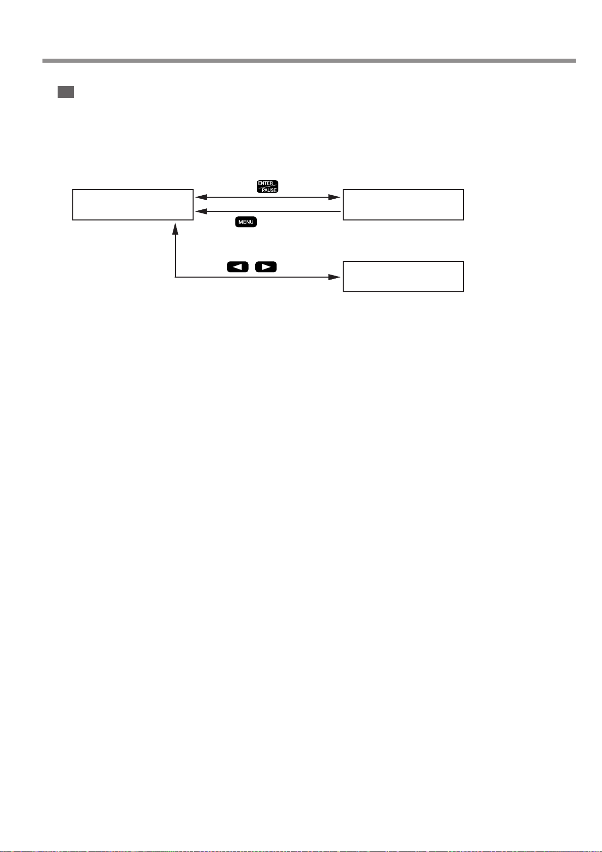
5-7. List of Commands
7 CUT-ZI
Function This moves the spindle head to the specified X, Y, and Z coordinates (at the specified feed rate, and via
the I and R levels).
Value ❶ Z-axis feed rate (0 to 50 mm/s)
Value ❷ X, Y, and Z coordinates for the movement destination
◆ Basic Screen
1:
7 CUT-ZI 50
➊
to cancel
◆ Detail Screen 1
X 1000 Y 1000
Z -500 8000RPM
◆ Detail Screen 2
X 1000 Y 1000
Z -500 Dest.
❷
❷
❷
This moves the spindle. The operation is as follows.
1. Move the Z axis at the highest speed to the height specified for [I LEVEL] at the [SETTING] submenu.
2. Move at the highest speed to the X and Y coordinates specified here.
3. Move the Z axis at the highest speed to the height specified for [R LEVEL] at the [SETTING] submenu.
4. Move at the specified speed to the Z coordinate specified here.
This command has no function for rotating or stopping the spindle.
◆ Basic Screen
Specify the Z-axis feed rate to use when moving from the R level to the specified Z-axis coordinate. Specifying [0] sets a
speed of 0.5 mm/s. After you input the speed, press the [ENTER/PAUSE] button to go to the settings at Detail Screen 1.
◆ Detail Screen 1
Specify the X, Y, and Z coordinates for the movement destination. At this screen you can use button operations to move
or rotate the spindle. You can decide on the movement destination as you verify the on-screen coordinate values and the
actual position. To set the present location of the spindle as the movement destination, press the [ENTER/PAUSE]
button. To cancel and return, press the [MENU] button.
◆ Detail Screen 2
This displays the X, Y, and Z coordinates of the set movement destination. Use this screen to verify the settings.
Chapter 5 - The Teaching Feature
91
Page 96
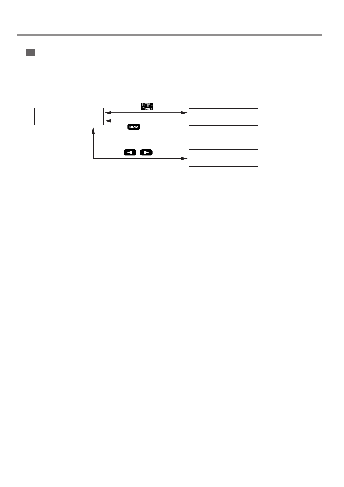
5-7. List of Commands
8 CUT-3
Function This moves the spindle head to the specified X, Y, and Z coordinates, moving all three axes simultaneously
(at the specified feed rate).
Value ❶ Feed rate (0 to 50 mm/s)
Value ❷ X, Y, and Z coordinates for the movement destination
◆ Basic Screen
1:
8 CUT-3 50
❶
to cancel
◆ Basic Screen
X 1000 Y 1000
Z -500 8000RPM
◆ Basic Screen
X 1000 Y 1000
Z -500 Dest.
❷
❷
❷
This moves the spindle at the specified feed rate. It moves all three axes simultaneously to the specified X, Y, and Z
coordinates. Unlike [CUT-ZM] and [CUT-ZI], it effects linear movement to the specified X, Y, and Z coordinates. This
command has no function for rotating or stopping the spindle.
◆ Basic Screen
Specify the feed rate. Specifying [0] sets a speed of 0.5 mm/s. After you input the speed, press the [ENTER/PAUSE]
button to go to the settings at Detail Screen 1.
◆ Detail Screen 1
Specify the X, Y, and Z coordinates for the movement destination. At this screen you can use button operations to move
or rotate the spindle. You can decide on the movement destination as you verify the on-screen coordinate values and the
actual position. To set the present location of the spindle as the movement destination, press the [ENTER/PAUSE]
button. To cancel and return, press the [MENU] button.
◆ Detail Screen 2
This displays the X, Y, and Z coordinates of the set movement destination. Use this screen to verify the settings.
92
Chapter 5 - The Teaching Feature
Page 97

5-7. List of Commands
9 ARC
Function This moves the spindle head in an arc.
Value ❶ Relative location from the start point to the center of the circle (X and Y coordinates)
Value ❷ Angle from the arc start point to end point (-360 to 360 deg.)
Value ❸ Resolution (0 to 120 deg.)
Value ❹ Feed rate (0 to 50 mm/s)
◆ Basic Screen
1:
9 ARC
◆ Detail Screen 1
RELATIVE CENTER
X 500 Y 500
◆ Detail Screen 2
SET ANGLE
---> 90
❶❶
to cancel
Y
to cancel
❷
Start point
X
Center
Angle
End point
◆ Detail Screen 3
SET TOLERANCE
---> 5
◆ Detail Screen 4
SET SPEED
---> 20
❸
❹
to cancel
to cancel
This moves from the present location in an arc of the specified angle. Arc movement is possible only on the X and Y
plane.
◆ Detail Screen 1
Specify the center of the circle. Specify relative coordinates from the present location, which is the start point. Note that
these are not coordinates referenced to the workpiece origin point. To go to Detail Screen 2, press the [ENTER/PAUSE]
button. To cancel and return, press the [MENU] button.
◆ Detail Screen 2
Specify the angle from the start point to the end point. The direction of turning is determined by whether the value is
positive or negative. A positive value yields counterclockwise turning and a negative value yields clockwise turning. To
go to Detail Screen 3, press the [ENTER/PAUSE] button. To cancel and return, press the [MENU] button.
◆ Detail Screen 3
Specify the resolution (smoothness) of the arc. Smaller values result in greater smoothness, but the apparent feed rate
becomes slower. Specifying [0] sets the machine's highest resolution. To go to Detail Screen 4, press the [ENTER/
PAUSE] button. To cancel and return, press the [MENU] button.
◆ Detail Screen 4
Specify the feed rate. Specifying [0] sets a speed of 0.5 mm/s. To finish setting the value, press the [ENTER/PAUSE]
button. To cancel and return, press the [MENU] button.
Chapter 5 - The Teaching Feature
93
Page 98

5-7. List of Commands
10 SP
Function This makes the settings for rotating or stopping the spindle, and for spindle rotating speed.
Value ❶ Rotation or no rotation (ON: rotation, OFF: stopped)
Value ❷ Spindle rotating speed (80 to 300 x 100 rpm)
1:
10 SP ON 80
This rotates the spindle at the specified spindle rotating speed, or stops rotation of the spindle. Commands to move the
spindle, such as [MOVE-ZM] and [CUT-ZM], do not rotate or stop the spindle by themselves. You specify this with the
[SP] command. A setting of [80], for example, sets a spindle rotating speed of 8,000 rpm.
❶❷
11 P
Function This controls the state of the output ports for expansion connector 2.
Value ❶ Output-port state (1: High, 0: Low, *: Maintain state)
1:
11 P 00000000
This command changes the state of the output ports for expansion connector 2. There are eight output port (numbered 1
through 8), and this controls the state (high or low) of each one. [*] means no change in state -- that is, to leave high if
high, or to leave low if low.
When you turn on the machine, all output ports are at the low state. When you execute this command to set a certain port
high, the port is maintained in that state until you switch off the power. (The state does not revert to low even when
sequence execution ends.) If initialization of the port is required, it is useful to insert a command such as [11 P 00000000]
at the start or end of the sequence.
For information about the specifications of expansion connector 2, see p.143 "Expansion Connector 2."
❶
Output port 1 Output port 8
00000000
12 WAIT
Function This stops sequence execution for the specified interval of time.
Value ❶ Wait time (0 to 10,000 ms)
1:
12 WAIT 10000
This pauses sequence execution, waits for the specified time interval, then resumes execution. A setting of [3000], for
example, specifies a wait time of 3 seconds.
❶
94
Chapter 5 - The Teaching Feature
Page 99

5-7. List of Commands
13 WAIT KEY
Function This pauses sequence execution and waits until any button is pressed.
Value None
This pauses sequence execution and goes into standby, displaying the following screen. Pressing any button on the
operation panel resumes execution.
PUSH ANY KEY
<13 WAIT KEY>
14 W
Function
Value ❶ Input-port state (1: High, 0: Low, *: Either)
1:
14 W 0000000
This goes into standby while monitoring the state of the input ports on expansion connector 2, and resumes execution
when the specified state occurs. Standby continues until all eight input ports go to the specified state (high or low). [*]
indicates that the state may be either high or low.
For information about the specifications of expansion connector 2, see p.143 "Expansion Connector 2."
This pauses sequence execution and waits until input ports on expansion connector 2 go to the specified state.
❶
Input port 1 Input port 2
00000000
15 BREAK
Function This pauses sequence execution and waits until any button is pressed.
Value None
This pauses sequence execution, displaying the following screen while in standby . Pressing any button on the operation
panel resumes execution.
PUSH ANY KEY
<15 BREAK>
This command is available only when [BREAK POINT] at the [SETTING] submenu is set to [ENABLE]. When this is
set to [DISABLE], the machine does not go into standby or display this screen. This point is different from the [WAIT
KEY] command.
16 JUMP
Function This jumps to the specified label.
Value ❶ Label name
1:
16 JUMP
This vary changes the order of step execution. Execution does not proceed to the next step, but instead jumps to the step
to which the specified label name has been assigned.
Label name
❶
Chapter 5 - The Teaching Feature
95
Page 100

5-7. List of Commands
17 J
Function This jumps to the specified label when an input port on expansion connector 2 is at the specified state.
Value ❶ Label name
Value ❷ Input port number (1 through 8)
Value ❸ Input-port state (1: High, 0: Low)
1:
17 J
Label name
This checks the state of an input port on expansion connector 2, then either executes a jump if the input port is at the
specified state or proceeds to the following step if not at the specified state. This checks one of the eight input ports and
determines whether it is at the specified state (high or low).
For information about the specifications of expansion connector 2, see p.143 "Expansion Connector 2."
❶❷❸
10
18 CALL
Function This jumps to the specified label, then returns to the original step.
Value ❶ Label name
1:
18 CALL
This jumps to the step to which the specified label name has been assigned. When a [RETURN] command is encountered
thereafter, execution returns to the step where the jump occurred and resumes with the following step. This is uses to call
a subroutine. You cannot call a second subroutine from within a first one (that is, nested subroutines are not permitted).
Label name
❶
19 C
Function This calls the specified label when an input port on expansion connector 2 is at the specified state.
Value ❶ Label name
Value ❷ Input port number (1 through 8)
Value ❸ Input-port state (1: High, 0: Low)
1:
19 C
Label name
This checks the state of an input port on expansion connector 2, then either executes a call if the input port is at the
specified state or proceeds to the following step if not at the specified state. This checks one of the eight input ports and
determines whether it is at the specified state (high or low).
For information about the specifications of expansion connector 2, see p.143 "Expansion Connector 2."
❷❸❶
10
20 RETURN
Function This signals the end of a subroutine called using a [CALL] or [C] command.
Value None
This is used in conjunction with the [CALL] or [C] command. When a [RETURN] command is executed after a jump
made using these commands, execution returns to the step where the jump occurred. Nothing happens if this command is
executed before a jump has been performed.
96
Chapter 5 - The Teaching Feature
 Loading...