

Page 1

IBM Sys tem Storage DS4700 Express Storage Subsystem
Installation, U ser’s and M ain t enance Guide
GC26-7843-05
Page 2

Page 3

IBM Sys tem Storage DS4700 Express Storage Subsystem
Installation, U ser’s and M ain t enance Guide
GC26-7843-05
Page 4

Note:
Before using this information and the product it supports, be sure to read the general information in the “Safety” on page xv
and “Notices” on page 215 sections.
Sixth Edition (November 2011)
© Copyright IBM Corporation 2010.
US Government Users Restricted Rights – Use, duplication or disclosure restricted by GSA ADP Schedule Contract
with IBM Corp.
Page 5

Contents
Figures ............................ix
Tables............................xiii
Safety ............................xv
About this document ......................xxi
Who should read this document ..................xxi
How this document is organized ..................xxi
DS4000 Storage Subsystem installation tasks - General overview ......xxii
Getting information, help, and service ................xxvi
Before you call .......................xxvi
Using the documentation....................xxvi
Finding DS4000 readme files ..................xxvii
Web sites .........................xxvii
Software service and support..................xxviii
Hardware service and support .................xxviii
Fire suppression systems ...................xxix
How to send your comments ..................xxix
Chapter 1. Introduction ......................1
Overview ...........................1
Models ...........................2
Operating system support ....................3
Fibre channel defined ......................3
SATA defined .........................3
Inventory checklist ........................3
Product updates and support notifications ...............5
Best practices guidelines......................5
Storage subsystem components ...................6
Enhanced Disk Drive Modules (E-DDMs) ...............7
Controllers ..........................8
Connectors, switch, and enclosure ID ...............8
Setting up IP addresses for DS4000 storage controllers ........11
AC power supply and fan units ..................12
DC power supply and fan units ..................14
Battery units .........................17
SFP modules ........................19
Telco bezel .........................19
Software and hardware compatibility and upgrades ...........20
Software and firmware support code upgrades ............21
Determining firmware levels ...................21
Specifications .........................22
Area requirements ......................22
Dimensions ........................22
Weight ..........................23
Shipping dimensions .....................23
Environmental requirements and specifications ............24
Temperature and humidity ...................24
Altitude..........................25
Airflow and heat dissipation ..................25
Shock and vibration requirements ................26
Acoustic noise .......................26
© Copyright IBM Corp. 2010 iii
Page 6

Electrical requirements .....................26
Power and site wiring requirements for models with ac power supply and
fan units ........................27
Power and site wiring requirements for models with dc power supply and
fan units ........................28
Heat output, airflow, and cooling .................28
Chapter 2. Installing the storage subsystem .............31
Installation overview .......................31
Handling static-sensitive devices ..................33
Preparing for installation .....................34
Tools and hardware required ...................35
Preparing the site .......................35
Preparing the rack cabinet....................36
Installing the support rails .....................36
Installing the DS4700 Express ...................40
Removing the CRUs ......................40
Removing a controller ....................41
Removing an ac power supply and fan unit ............42
Removing a dc power supply and fan unit .............43
Removing an E-DDM ....................45
Installing the DS4700 Express into a rack on the support rails ......46
Replacing the components ...................48
Replacing a controller ....................48
Replacing an ac power supply and fan unit ............49
Replacing a dc power supply and fan unit .............50
Replacing an E-DDM ....................52
Installing a Telco bezel ....................53
Chapter 3. Cabling the storage subsystem..............55
Enclosure ID settings ......................55
Fibre-channel loop and ID settings..................56
Working with SFPs and fiber-optic cables ...............56
Handling fibre-optic cables ...................57
Installing SFP modules .....................58
Removing SFP modules ....................60
Using LC-LC fibre-channel cables .................61
Connecting an LC-LC cable to an SFP module ...........62
Removing an LC-LC fibre-channel cable .............64
Using LC-SC fibre-channel cable adapters ..............64
Connecting an LC-SC cable adapter to a device ..........65
Removing an LC-LC cable from an LC-SC cable adapter .......66
Connecting storage expansion enclosures to the DS4700 Express ......68
Redundant drive channel pair ..................68
Overview of steps to connect storage expansion enclosures to a storage
subsystem.........................69
DS4700 Express Storage Subsystem drive cabling topologies ......70
One DS4700 Express and one storage expansion enclosure ......72
One DS4700 Express and two storage expansion enclosures......72
One DS4700 Express and three storage expansion enclosures .....74
One DS4700 Express and four storage expansion enclosures .....74
One DS4700 Express and up to six storage expansion enclosures ....74
One DS4700 Express and two or more storage expansion enclosures in a
mixed configuration ....................76
DS4700 Express Storage Subsystem and supported storage expansion
enclosure drive cabling schemes ................77
iv IBM System Storage DS4700 Express Storage Subsystem: Installation, User’s and Maintenance Guide
Page 7

DS4700 Express Storage Subsystem drive cabling rules and
recommendations .....................78
One DS4700 Express and one EXP100 storage expansion enclosure. . . 80
One DS4700 Express and two EXP100 storage expansion enclosures 81
One DS4700 Express and three or more EXP100 storage expansion
enclosures........................82
One DS4700 Express and one EXP710 storage expansion enclosure. . . 85
One DS4700 Express and two EXP710 storage expansion enclosures 85
One DS4700 Express and three or more EXP710 storage expansion
enclosures........................86
One DS4700 Express and one EXP810 storage expansion enclosure. . . 89
One DS4700 Express and two EXP810 storage expansion enclosures 89
One DS4700 Express and three or more EXP810 storage expansion
enclosures........................90
One DS4700 Express and two or more storage expansion enclosures in a
mixed configuration ....................94
Storage expansion enclosure settings ...............97
Fibre channel loop and ID settings................97
DS4000 storage expansion enclosure ID settings ..........97
Intermixing storage expansion enclosures in the same drive loop ......99
Connecting secondary interface cables ...............100
Configuring the storage subsystem .................101
Storage subsystem management methods .............101
Host-agent (in-band) management method ............102
Direct (out-of-band) management method ............102
Connecting hosts to the DS4700 Express .............104
Fibre channel connections ...................107
Fibre channel host loop configurations ...............107
Redundant host and drive loops ................108
Installing the storage subsystem configuration .............110
Cabling the ac power supply for ac models ..............111
Cabling the dc power supply for dc models ..............111
Single-level redundant dc cabling.................112
Dual-level redundant dc cabling .................113
Chapter 4. Operating the storage subsystem ............117
Performing the DS4000 Health Check process .............117
Web pages .........................118
Hardware responsibilities ....................118
Powering on the storage subsystem.................119
Turning on the storage subsystem ................119
Installing the DS4000 Storage Manager client .............121
Monitoring status through software .................122
Finding controller, storage expansion enclosure, and drive information 123
Firmware updates ......................124
Troubleshooting the storage subsystem ..............124
Checking the LEDs .......................125
AC power supply and fan unit LEDs ...............126
DC power supply and fan unit LEDs ...............126
Front LEDs .........................127
Battery unit LEDs ......................128
Controller LEDs .......................129
Seven-segment numeric display LEDs ...............132
Powering off the storage subsystem.................133
Turning off the storage subsystem ................134
Performing an emergency shutdown ...............136
Contents v
Page 8

Restoring power after an unexpected shutdown ...........137
Recovering from an overheated power supply and fan unit ........138
Cache memory and cache battery .................140
Cache memory .......................141
Subsystem cache battery ...................142
Chapter 5. Replacing components ................145
Handling static-sensitive devices ..................145
Service Action Allowed Status LED .................145
Replacing a controller ......................146
Removing and replacing a bezel ..................150
Replacing a filter and filter retainer .................151
Working with hot-swap E-DDMs ..................151
Installing hot-swap E-DDMs...................153
Replacing hot-swap E-DDMs ..................155
Replacing multiple E-DDMs ...................156
Replacing all E-DDMs at the same time .............157
Replacing the E-DDMs one at a time ..............159
Verifying the Link Rate setting ..................161
Replacing an ac power supply and fan unit ..............164
Replacing a dc power supply and fan unit ..............169
Replacing a battery unit .....................175
Replacing an SFP module ....................177
Replacing a midplane ......................178
Chapter 6. Hardware maintenance ................183
General checkout .......................183
Solving problems .......................183
Parts listing..........................188
Appendix A. Records .....................191
Identification numbers ......................191
Storage subsystem and controller information record ..........192
Sample information record ...................193
Installed device records .....................194
Appendix B. Rack mounting template ...............195
Appendix C. Power cords ....................199
Appendix D. Additional DS4000 documentation ...........203
DS4000 Storage Manager Version 10 library .............203
DS4800 Storage Subsystem library .................204
DS4700 Storage Subsystem library .................205
DS4500 Storage Subsystem library .................206
DS4400 Storage Subsystem library .................207
DS4300 Storage Subsystem library .................208
DS4200 Express Storage Subsystem library .............209
DS4100 Storage Subsystem library .................210
DS4000 Storage Expansion Enclosure documents ...........211
Other DS4000 and DS4000-related documents ............212
Appendix E. Accessibility ....................213
Notices ...........................215
Trademarks..........................215
vi IBM System Storage DS4700 Express Storage Subsystem: Installation, User’s and Maintenance Guide
Page 9

Important notes ........................216
Particulate contamination.....................217
Documentation format ......................217
Electronic emission notices ....................218
Federal Communications Commission (FCC) statement ........218
Industry Canada Class A emission compliance statement ........218
Avis de conformité à la réglementation d'Industrie Canada .......218
Australia and New Zealand Class A statement ............218
European Union EMC Directive conformance statement ........218
Taiwanese Class A warning statement ...............219
Germany Electromagnetic Compatibility Directive ...........219
Deutschland: Einhaltung des Gesetzes über die elektromagnetische
Verträglichkeit von Geräten .................220
Zulassungsbescheinigung laut dem Deutschen Gesetz über die
elektromagnetische Verträglichkeit von Geräten (EMVG) (bzw. der EMC
EG Richtlinie 2004/108/EG) für Geräte der Klasse A ........220
People's Republic of China Class A warning statement.........220
Japan Voluntary Control Council for Interference (VCCI) Class A Statement 220
Japan Electronics and Information Technology Industries Association (JEITA)
Statement (less than or equal to 20 A per phase) ..........220
Korean Communications Commission (KCC) Class A Statement .....220
Glossary ..........................221
Index ............................231
Contents vii
Page 10

viii IBM System Storage DS4700 Express Storage Subsystem: Installation, User’s and Maintenance Guide
Page 11

Figures
1. DS4700 Express hot-swap drive bays .......................7
2. Back view; connectors, switch, ports, enclosure ID on model 70 .............10
3. Back view; connectors, switch, ports, enclosure ID on model 72 .............10
4. Power supply and fan unit components for DS4700 Express model 70 ...........13
5. Power supply and fan unit components for DS4700 Express model 72 ...........13
6. Power supply and fan unit and airflow .......................14
7. DC power supply and fan unit ..........................15
8. DC power supply and fan unit for DS4700 Express model 70 ..............15
9. DC power supply and fan unit for DS4700 Express model 72 ..............16
10. Battery unit .................................18
11. SFP module and fiber optic cable.........................19
12. Bezel ...................................20
13. Filter and filter retainer .............................20
14. DS4700 Express dimensions ..........................23
15. DS4700 Express airflow ............................25
16. Example of cold aisle/hot aisle rack configuration ...................29
17. Example of DS4700 Express serial number, machine type, and model number location .....32
18. Front rack mounting template ..........................37
19. Rear rack mounting template ..........................38
20. Installing the support rails ...........................40
21. Removing and replacing a controller........................42
22. Removing a power supply and fan unit.......................43
23. Removing a dc power supply and fan unit .....................45
24. Removing a E-DDM CRU ...........................46
25. Installing the DS4700 Express ..........................47
26. Securing the DS4700 Express to the rack cabinet...................48
27. Removing and replacing a controller........................49
28. Replacing a power supply and fan unit .......................50
29. Replacing a dc power supply and fan unit .....................52
30. Replacing an E-DDM .............................53
31. Installing a Telco bezel.............................54
32. Storage subsystem seven-segment enclosure ID on models 70 and 72 ...........56
33. Recommended bending and looping specifications for fibre-optic cables ..........58
34. SFP module and protective cap .........................60
35. Installing an SFP module into the host port .....................60
36. Unlocking the SFP module latch - plastic variety ...................61
37. Unlocking the SFP module latch - wire variety ....................61
38. LC-LC fibre-channel cable ...........................62
39. Removing fiber-optic cable protective caps .....................63
40. Inserting an LC-LC fibre-channel cable into an SFP module ...............63
41. LC-LC fibre-channel cable lever and latches .....................64
42. Removing the LC-LC fibre-channel cable ......................64
43. LC-SC fibre-channel cable adapter ........................65
44. Removing the LC-SC cable adapter protective caps ..................66
45. Connecting an LC-LC cable into the LC-SC cable adapter ...............66
46. LC-LC fibre-channel cable lever and latches .....................67
47. Removing the LC-LC fibre-channel cable from an LC-SC fibre-channel cable adapter .....67
48. Example of a redundant drive channel pair .....................69
49. DS4700 Express Storage Subsystem (Model 70) ports and controllers ...........71
50. DS4700 Express Storage Subsystem (Model 72) ports and controllers ...........71
51. One DS4700 Express and one storage expansion enclosure — Recommended cabling .....72
52. One DS4700 Express and two storage expansion enclosure — Not recommended cabling 73
53. One DS4700 Express and two storage expansion enclosure — Recommended cabling .....73
© Copyright IBM Corp. 2010 ix
Page 12

54. One DS4700 Express and three storage expansion enclosure — Recommended cabling ....74
55. One DS4700 Express and four storage expansion enclosure — Recommended cabling.....74
56. One DS4700 Express and up to six storage expansion enclosure — Recommended cabling 75
57. One DS4700 Express and up to six storage expansion enclosure — Not recommended ....76
58. One DS4700 Express and two or more storage expansion enclosures in a mixed environment —
Recommended cabling ............................77
59. DS4700 Express drive ports connected to EXP810 ESM ports labeled 1B ..........79
60. DS4700 Express drive ports connected to 14-drive storage expansion enclosure ESM In and Out
ports ...................................80
61. One DS4700 Express and one EXP100 storage expansion enclosure — Recommended cabling 81
62. One DS4700 Express and two EXP100 storage expansion enclosures behind a pair of DS4700
drive ports .................................81
63. One DS4700 Express and three EXP100 storage expansion enclosures behind a pair of DS4700
drive ports .................................82
64. One DS4700 Express and four EXP100 storage expansion enclosures behind a pair of DS4700
drive ports .................................83
65. One DS4700 Express and a maximum of six EXP100 storage expansion enclosures behind a pair
of DS4700 drive ports .............................84
66. One DS4700 Express and one EXP710 storage expansion enclosure — Recommended cabling 85
67. One DS4700 Express and two EXP710 storage expansion enclosures behind a pair of DS4700
drive ports .................................85
68. One DS4700 Express and three EXP710 storage expansion enclosures behind a pair of DS4700
drive ports .................................86
69. One DS4700 Express and four EXP710 storage expansion enclosures behind a pair of DS4700
drive ports .................................87
70. One DS4700 Express and a maximum of six EXP710 storage expansion enclosures behind a pair
of DS4700 drive ports .............................88
71. One DS4700 Express and one EXP810 storage expansion enclosure — Recommended cabling 89
72. One DS4700 Express and two EXP810 storage expansion enclosures behind a pair of DS4700
drive ports .................................90
73. One DS4700 Express and three EXP810 storage expansion enclosures behind a pair of DS4700
drive ports .................................91
74. One DS4700 Express and four EXP810 storage expansion enclosures behind a pair of DS4700
drive ports .................................92
75. One DS4700 Express and a maximum of six EXP810 storage expansion enclosures behind a pair
of DS4700 drive ports .............................93
76. Acceptable EXP710, EXP810 and EXP100 intermix configuration in a DS4700 Express Storage
Subsystem environment ............................95
77. Unacceptable EXP710, EXP810 and EXP100 intermix configuration in a DS4700 Express Storage
Subsystem environment ............................96
78. Cabling variations when intermixing EXP100, EXP710, and EXP810 storage expansion
enclosures behind a DS4700 Express Storage Subsystem ...............97
79. Ethernet and serial port locations on DS4700 Express model 70 .............100
80. Ethernet and serial port locations on DS4700 Express model 72 .............101
81. Host-agent (in-band) managed storage subsystems .................102
82. Direct (out-of-band) managed storage subsystems ..................104
83. Location of host cables on RAID controllers on model 70 of the DS4700 Express ......105
84. Location of host cables on RAID controllers on model 72 of the DS4700 Express ......105
85. Cabling diagram for two redundant host connections .................106
86. Cabling diagram for four redundant host connections .................107
87. Examples of redundant host direct attached fibre channel configurations ..........108
88. Example of a single SAN fabric configuration ....................109
89. Example of a dual SAN fabric configuration ....................109
90. Example of two storage subsystems in a dual SAN environment .............110
91. Example of a two-cluster configuration ......................110
92. DC power supply and fan unit cabling scheme - single-level redundancy ..........113
x IBM System Storage DS4700 Express Storage Subsystem: Installation, User’s and Maintenance Guide
Page 13

93. DC power supply and fan unit cabling scheme - dual-level redundancy ..........114
94. DC power supply connector - PIN positions ....................114
95. DC wiring from DS4700 Express to disconnect device and dc power source ........115
96. Power supply and fan unit LEDs.........................126
97. DC power supply and fan unit LEDs .......................127
98. Front LEDs and controls ...........................128
99. Battery unit LEDs ..............................129
100. Rear controller LEDs, controls, and connectors - Model 70 ...............130
101. Rear controller LEDs, controls, and connectors - Model 72 ...............130
102. Numeric display LEDs ............................132
103. Cache Active LEDs .............................141
104. Battery unit LEDs ..............................143
105. Unlocking the SFP module latch - plastic variety ...................147
106. Unlocking the SFP module latch - wire variety ...................148
107. Removing a controller from the DS4700 Express ..................148
108. Installing a controller .............................149
109. Removing and replacing a bezel.........................150
110. Hot-swap E-DDM LEDs ............................154
111. E-DDM CRU handle .............................154
112. Link rate LEDs ...............................163
113. Link rate switch ...............................163
114. Replacing a power supply and fan unit ......................168
115. Replacing a dc power supply and fan unit .....................174
116. Removing and replacing a battery unit from the controller chassis ............176
117. Replacing an SFP module ...........................178
118. Front cage frame screw locations ........................180
119. Screws holding the top and bottom sides of the chassis to the cage frame .........181
120. DS4700 Express Storage Subsystem parts list ...................189
121. Front rack mounting template ..........................196
122. Rear rack mounting template ..........................197
Figures xi
Page 14

xii IBM System Storage DS4700 Express Storage Subsystem: Installation, User’s and Maintenance Guide
Page 15

Tables
1. Where to find DS4000 installation and configuration procedures .............xxii
2. Description of Figure 2 on page 10 ........................10
3. Description of Figure 3 on page 10 ........................10
4. Description of Figure 4 on page 13 ........................13
5. Description of Figure 5 on page 13 ........................13
6. DC power supply and fan unit description for DS4700 Express model 70 ..........15
7. DC power supply and fan unit description for DS4700 Express model 72 ..........16
8. Description of Figure 10 on page 18........................18
9. Filter and filter retainer description ........................20
10. DS4700 Express weights ............................23
11. DS4700 Express component weights .......................23
12. DS4700 Express shipping carton dimensions ....................23
13. Temperature and humidity requirements for storage subsystem when in storage or in transit 24
14. Temperature and humidity requirements for storage subsystem in a typical Information Technology
(IT) or office environment............................24
15. Temperature and humidity requirements for storage subsystem in a Telco/NEBS-3 compliant
environment ................................24
16. DS4700 Express altitude ranges .........................25
17. DS4700 Express power and heat dissipation ....................26
18. Random vibration power spectral density ......................26
19. DS4700 Express sound levels ..........................26
20. DS4700 Express ac power requirements ......................27
21. DS4700 Express dc power requirements ......................27
22. Description of Figure 32 on page 56........................56
23. DS4700 Express Storage Subsystem (Model 70) host ports and drive channels........71
24. DS4700 Express Storage Subsystem (Model 72) host ports and drive channels........71
25. DS4700 Express drive ports connected to EXP810 ESM ports labeled 1B ..........79
26. DS4700 Express drive ports connected to 14-drive storage expansion enclosure ESM In and Out
ports ...................................80
27. Description of Figure 76 ............................95
28. Description of Figure 77 ............................96
29. Description of Figure 78 ............................97
30. Recommended enclosure ID settings scheme when connecting a DS4700 to EXP710s or
EXP100s..................................98
31. Possible combinations of 14-drive and 16-drive storage expansion enclosures per redundant
drive/channel loop pair in a DS4700 Express configuration ...............99
32. DS4700 Express Storage Subsystem (Model 72) location of host ports on controllers .....101
33. DS4700 Express Storage Subsystem (Model 72) location of host ports on controllers .....101
34. Description of Figure 61............................102
35. Description of Figure 62............................104
36. DS4700 Express Storage Subsystem (Model 70) location of host ports on controllers .....105
37. DS4700 Express Storage Subsystem (Model 72) location of host ports on controllers .....105
38. DC power supply connector - PIN descriptions ...................114
39. DC power source wiring descriptions .......................115
40. Power supply and fan unit LEDs.........................126
41. DC power supply and fan unit LEDs .......................127
42. Front LEDs and controls ...........................128
43. Battery unit LEDs ..............................129
44. Rear controller LEDs, controls, and connectors ...................130
45. Host and drive channel LED definitions ......................132
46. Numeric display diagnostic codes ........................133
47. Description of Figure 103 on page 141 ......................141
48. Battery unit LEDs ..............................143
© Copyright IBM Corp. 2010 xiii
Page 16

49. Drive LED activity ..............................152
50. Data transfer rates for drive modules .......................162
51. Symptom-to-FRU index ............................184
52. Parts listing (DS4700 Express Storage Subsystem)..................189
53. Storage subsystem and controller information record .................192
54. Sample information record ...........................193
55. Hard disk drive record ............................194
56. IBM power cords ..............................199
57. DS4000 Storage Manager Version 10 titles by user tasks ...............203
58. DS4800 Storage Subsystem document titles by user tasks ...............204
59. DS4700 Storage Subsystem document titles by user tasks ...............205
60. DS4500 Storage Subsystem document titles by user tasks ...............206
61. DS4400 Storage Subsystem document titles by user tasks ...............207
62. DS4300 Storage Subsystem document titles by user tasks ...............208
63. DS4200 Express Storage Subsystem document titles by user tasks ...........209
64. DS4100 Storage Subsystem document titles by user tasks ...............210
65. DS4000 Storage Expansion Enclosure document titles by user tasks ...........211
66. DS4000 and DS4000–related document titles by user tasks ..............212
67. DS4000 Storage Manager alternate keyboard operations ...............213
68. Limits for particulates and gases ........................217
xiv IBM System Storage DS4700 Express Storage Subsystem: Installation, User’s and Maintenance Guide
Page 17
Safety
The caution and danger statements that this document contains can be referenced
in the multilingual IBM®Safety Information document that is provided with your IBM
System Storage
statement is numbered for easy reference to the corresponding statements in the
translated document.
v Danger: These statements indicate situations that can be potentially lethal or
extremely hazardous to you. A danger statement is placed just before the
description of a potentially lethal or extremely hazardous procedure, step, or
situation.
v Caution: These statements indicate situations that can be potentially hazardous
to you. A caution statement is placed just before the description of a potentially
hazardous procedure step or situation.
v Attention: These notices indicate possible damage to programs, devices, or
data. An attention notice is placed just before the instruction or situation in which
damage could occur.
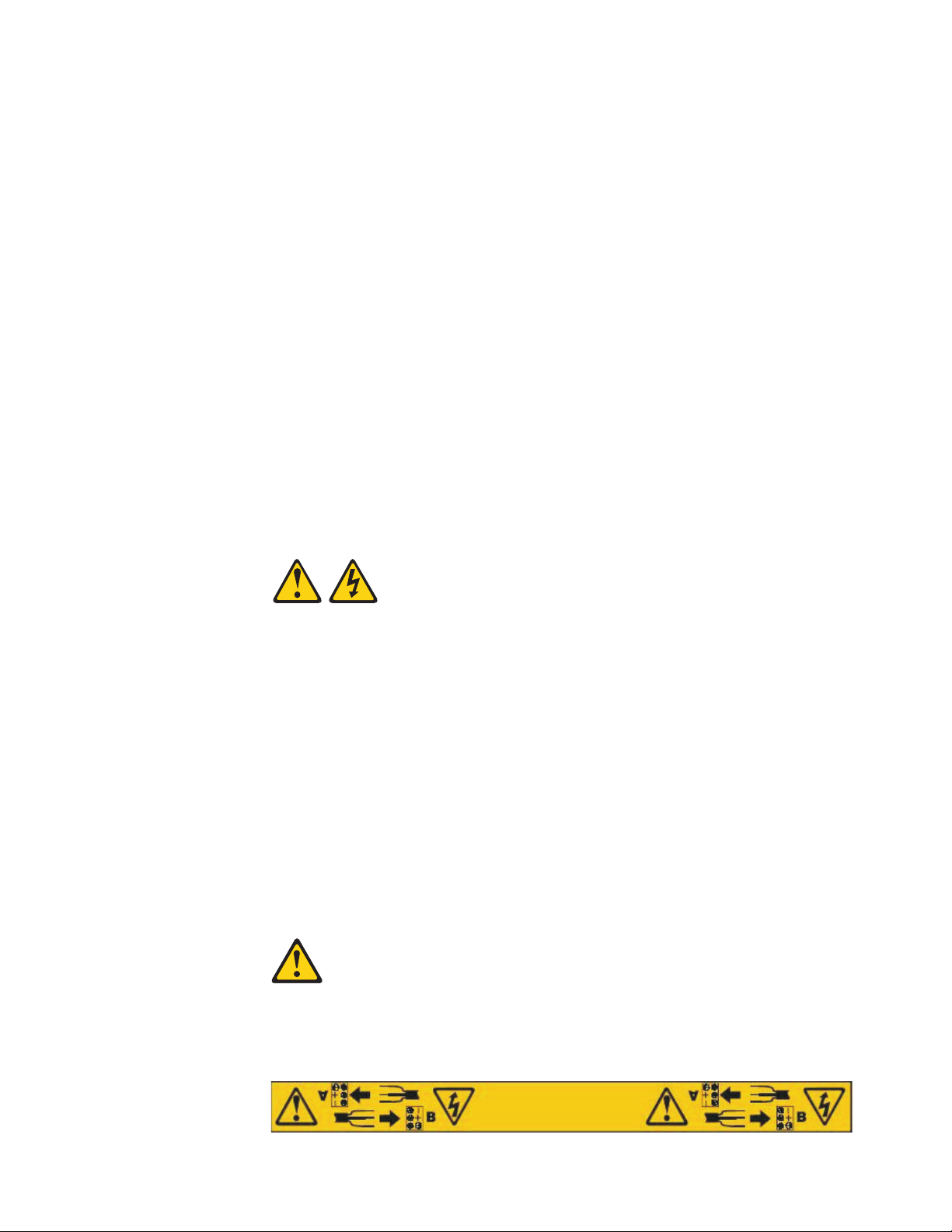
Before installing this product, read the following danger and caution notices.
Statement 1:
®
DS4700 Express Storage Subsystem. Each caution and danger
© Copyright IBM Corp. 2010 xv
Page 18
DANGER
Electrical current from power, telephone, and communication cables is
hazardous.
To avoid a shock hazard:
v Do not connect or disconnect any cables or perform installation,
maintenance, or reconfiguration of this product during an electrical
storm.
v Connect all power cords to a properly wired and grounded electrical
outlet.
v Connect to properly wired outlets any equipment that will be attached to
this product.
v When possible, use one hand only to connect or disconnect signal
cables.
v Never turn on any equipment when there is evidence of fire, water, or
structural damage.
v Disconnect the attached power cords, telecommunications systems,
networks, and modems before you open the device covers, unless
instructed otherwise in the installation and configuration procedures.
v Connect and disconnect cables as described in the following table when
installing, moving, or opening covers on this product or attached
devices.
To Connect: To Disconnect:
1. Turn everything OFF.
2. First, attach all cables to devices.
3. Attach signal cables to connectors.
4. Attach power cords to outlet.
5. Turn device ON.
1. Turn everything OFF.
2. First, remove power cords from outlet.
3. Remove signal cables from connectors.
4. Remove all cables from devices.
Statement 2:
CAUTION:
When replacing the lithium battery, use only an equivalent type battery
recommended by the manufacturer. If your system has a module containing a
lithium battery, replace it only with the same module type made by the same
manufacturer. The battery contains lithium and can explode if not properly
used, handled, or disposed of.
Do not:
v Throw or immerse into water
v Heat to more than 100° C (212° F)
v Repair or disassemble
Dispose of the battery as required by local ordinances or regulations.
Statement 3:
xvi IBM System Storage DS4700 Express Storage Subsystem: Installation, User’s and Maintenance Guide
Page 19
CAUTION:
When laser products (such as CD-ROMs, DVD drives, fiber optic devices, or
transmitters) are installed, note the following:
v Do not remove the covers. Removing the covers of the laser product could
result in exposure to hazardous laser radiation. There are no serviceable
parts inside the device.
v Use of controls or adjustments or performance of procedures other than
those specified herein might result in hazardous radiation exposure.
DANGER
Some laser products contain an embedded Class 3A or Class 3B laser
diode. Note the following.
Laser radiation when open. Do not stare into the beam, do not view directly
with optical instruments, and avoid direct exposure to the beam.
Class 1 Laser statement
Class 1 Laser Product
Laser Klasse 1
Laser Klass 1
Luokan 1 Laserlaite
Apparell Laser de Calsse 1À
IEC 825-11993 CENELEC EN 60 825
Statement 4:
≥ 18 kg (39.7 lb) ≥ 32 kg (70.5 lb) ≥ 55 kg (121.2 lb)
CAUTION:
Use safe practices when lifting.
Safety xvii
Page 20
Statement 5:
CAUTION:
The power control button on the device and the power switch on the power
supply do not turn off the electrical current supplied to the device. The device
also might have more than one power cord. To remove all electrical current
from the device, ensure that all power cords are disconnected from the power
source.
2
1
Statement 8:
CAUTION:
Never remove the cover on a power supply or any part that has the following
label attached.
Hazardous voltage, current, and energy levels are present inside any
component that has this label attached. There are no serviceable parts inside
these components. If you suspect a problem with one of these parts, contact
a service technician.
Statement 29:
xviii IBM System Storage DS4700 Express Storage Subsystem: Installation, User’s and Maintenance Guide
Page 21
CAUTION:
This equipment is designed to permit the connection of the earthed conductor
of the dc supply circuit to the earthing conductor at the equipment.
This equipment is designed to permit the connection of the earthed conductor
of the dc supply circuit to the earthing conductor at the equipment. If this
connection is made, all of the following conditions must be met:
v This equipment shall be connected directly to the dc supply system
earthing electrode conductor or to a bonding jumper from an earthing
terminal bar or bus to which the dc supply system earthing electrode
conductor is connected.
v This equipment shall be located in the same immediate area (such as,
adjacent cabinets) as any other equipment that has a connection between
the earthed conductor of the same dc supply circuit and the earthing
conductor, and also the point of earthing of the dc system. The dc system
shall not be earthed elsewhere.
v The dc supply source shall be located within the same premises as this
equipment.
v Switching or disconnecting devices shall not be in the earthed circuit
conductor between the dc source and the point of connection of the
earthing electrode conductor.
Statement 30:
CAUTION:
To reduce the risk of electric shock or energy hazards:
v This equipment must be installed by trained service personnel in a
restricted-access location, as defined by the NEC and IEC 60950-1, First
Edition, The Standard for Safety of Information Technology Equipment.
v Connect the equipment to a reliably grounded safety extra low voltage
(SELV) source. An SELV source is a secondary circuit that is designed so
that normal and single fault conditions do not cause the voltages to exceed
a safe level (60 V direct current).
v The branch circuit overcurrent protection must be rated 20 A.
v Use 12 American Wire Gauge (AWG) or 2.5 mm2 copper conductor only, not
exceeding 4.5 meters in length.
v Incorporate a readily available approved and rated disconnect device in the
field wiring.
CAUTION:
This unit has more than one power source. To remove all power from the unit,
all dc MAINS must be disconnected.
Safety xix
Page 22

Cable Warning:
WARNING: Handling the cord on this product or cords associated with accessories
sold with this product, will expose you to lead, a chemical known to the State of
California to cause cancer, and birth defects or other reproductive harm. Wash
hands after handling.
xx IBM System Storage DS4700 Express Storage Subsystem: Installation, User’s and Maintenance Guide
Page 23

About this document
This document provides instructions for installing and customizing the configuration
of your IBM System Storage DS4700 Express Storage Subsystem. It also provides
maintenance procedures and troubleshooting information.
Who should read this document
This document is intended for system operators and service technicians who have
extensive knowledge of Fibre Channel and network technology.
How this document is organized
Chapter 1, “Introduction,” on page 1 describes the IBM System Storage DS4700
Express Storage Subsystem. This chapter includes an inventory checklist and an
overview of the storage subsystem features, operating specifications, and
components.
Chapter 2, “Installing the storage subsystem,” on page 31 contains information on
how to install the DS4700 Express Storage Subsystem in a standard rack cabinet
and setting the interface options.
Chapter 3, “Cabling the storage subsystem,” on page 55 contains fibre channel and
power cabling information for the DS4700 Express Storage Subsystem.
Chapter 4, “Operating the storage subsystem,” on page 117 contains information on
how to power on and off the DS4700 Express Storage Subsystem, recover from an
overheated power supply and fan unit, troubleshoot, and interpret LEDs.
Chapter 5, “Replacing components,” on page 145 contains step-by-step instructions
about how to install or remove customer replaceable units (CRUs), such as
Enhanced Disk Drive Modules (E-DDMs), power supply and fan units, RAID
controllers, battery units, bezels, filter and filter retainer, midplane, and SFP
modules.
Chapter 6, “Hardware maintenance,” on page 183 describes problems and
symptoms that are specific to the DS4700 Express Storage Subsystem. It also
provides a parts list for the DS4700 Express Storage Subsystem.
Appendix A, “Records,” on page 191 provides a table that you can use to record
and update important information about your DS4700 Express Storage Subsystem,
including serial number and device records.
Appendix B, “Rack mounting template,” on page 195 provides the rack mounting
templates for installation of the DS4700 Express Storage Subsystem. If you want to
tear out the templates from the document for use during installation, use these
copies of the templates.
Appendix C, “Power cords,” on page 199 lists power cord information for the
DS4700 Express Storage Subsystem.
Appendix D, “Additional DS4000 documentation,” on page 203 lists additional
DS4000 documents.
© Copyright IBM Corp. 2010 xxi
Page 24

Appendix E, “Accessibility,” on page 213 details accessibility information.
DS4000 Storage Subsystem installation tasks - General overview
Table 1 provides a sequential list of many installation and configuration tasks that
are common to most DS4000 configurations. When you install and configure your
DS4000 storage subsystem, refer to this table to find the documentation that
explains how to complete each task.
Table 1. Where to find DS4000 installation and configuration procedures
Installation task Where to find information or procedures
1 Plan the installation
2 Mount the DS4000
storage subsystem in
the rack
v DS4000 Storage Manager Concepts Guide
v DS4000 Storage Manager Installation and Host Support
Guide for AIX, HP-UX, Solaris, and Linux on POWER
v DS4000 Storage Manager Installation and Host Support
Guide for Windows 2000/Server 2003/2008, NetWare,
VMWare ESX Server, and Linux
v DS4100 Storage Subsystem Installation, User’s, and
Maintenance Guide
v DS4200 Express Storage Subsystem Installation, User’s, and
Maintenance Guide
v DS4300 Storage Subsystem Installation, User's, and
Maintenance Guide
v DS4400 Fibre Channel Storage Server Installation and
Support Guide
v DS4500 Storage Subsystem Installation, User's, and
Maintenance Guide
v DS4700 Express Storage Subsystem Installation, User’s, and
Maintenance Guide
v IBM System Storage Quick Start Guide, Quick reference for
the DS4800
v DS4800 Storage Subsystem Installation, User’s, and
Maintenance Guide
v IBM System Storage Quick Start Guide, Quick reference for
the DS4700 and DS4200, Sections 2, 3, and 4 also for
installing the EXP810 and EXP420
v DS4800 Storage Subsystem Installation, User’s, and
Maintenance Guide
v IBM System Storage Quick Start Guide, Quick reference for
the DS4800
v DS4700 Express Storage Subsystem Installation, User’s, and
Maintenance Guide
v IBM System Storage Quick Start Guide, Quick reference for
the DS4700 and DS4200, Sections 2, 3, and 4 also for
installing the EXP810 and EXP420
v DS4400 and DS4500 Rack Mounting Instructions
v DS4300 Rack Mounting Instructions
v DS4200 Express Storage Subsystem Installation, User’s, and
Maintenance Guide
v DS4100 Storage Subsystem Installation, User’s and
Maintenance Guide
xxii IBM System Storage DS4700 Express Storage Subsystem: Installation, User’s and Maintenance Guide
Page 25

Table 1. Where to find DS4000 installation and configuration procedures (continued)
Installation task Where to find information or procedures
3 Mount the DS4000
EXP storage
expansion unit in the
rack
v DS4000 EXP100 Storage Expansion Unit Installation, User’s
and Maintenance Guide
v DS4000 EXP420 Storage Expansion Enclosures Installation,
User’s, and Maintenance Guide
v DS4000 EXP700 and EXP710 Storage Expansion Enclosures
Installation, User’s, and Maintenance Guide
v DS4000 EXP810 Storage Expansion Enclosures Installation,
User’s, and Maintenance Guide
v FAStT EXP500 Installation and User’s Guide
v IBM System Storage Quick Start Guide, Quick reference for
the DS4700 and DS4200, Sections 2, 3, and 4 also for
installing the EXP810 and EXP420
4 Route the storage
expansion unit fibre
channel cables
v DS4100 Storage Subsystem Installation, User’s, and
Maintenance Guide
v DS4200 Express Storage Subsystem Installation, User’s, and
Maintenance Guide
v DS4300 Storage Subsystem Installation, User’s, and
Maintenance Guide
v DS4400 Fibre Channel Cabling Instructions
v DS4500 Storage Subsystem Installation, User’s, and
Maintenance Guide
v DS4700 Express Storage Subsystem Installation, User’s, and
Maintenance Guide
v IBM System Storage Quick Start Guide, Quick reference for
the DS4700 and DS4200, Sections 2, 3, and 4 also for
installing the EXP810 and EXP420
v DS4800 Storage Subsystem Installation, User’s, and
Maintenance Guide
v IBM System Storage Quick Start Guide, Quick reference for
the DS4800
5 Route the host
server fibre channel
cables
v DS4100 Storage Subsystem Installation, User’s, and
Maintenance Guide
v DS4200 Express Storage Subsystem Installation, User’s, and
Maintenance Guide
v DS4300 Storage Subsystem Installation, User’s, and
Maintenance Guide
v DS4400 Fibre Channel Cabling Instructions
v DS4500 Storage Subsystem Installation, User’s, and
Maintenance Guide
v DS4700 Express Storage Subsystem Installation, User’s, and
Maintenance Guide
v IBM System Storage Quick Start Guide, Quick reference for
the DS4700 and DS4200, Sections 2, 3, and 4 also for
installing the EXP810 and EXP420
v DS4800 Storage Subsystem Installation, User’s, and
Maintenance Guide
v IBM System Storage Quick Start Guide, Quick reference for
the DS4800
About this document xxiii
Page 26

Table 1. Where to find DS4000 installation and configuration procedures (continued)
Installation task Where to find information or procedures
6 Power up the
subsystem
7 Configure DS4000
network settings
8 Zone the fabric
switch
(SAN-attached only)
v DS4100 Storage Subsystem Installation, User’s, and
Maintenance Guide
v DS4200 Express Storage Subsystem Installation, User’s, and
Maintenance Guide
v DS4300 Storage Subsystem Installation, User’s, and
Maintenance Guide
v DS4400 Fibre Channel Storage Server Installation and
Support Guide
v DS4500 Storage Subsystem Installation, User’s, and
Maintenance Guide
v DS4700 Express Storage Subsystem Installation, User’s, and
Maintenance Guide
v IBM System Storage Quick Start Guide, Quick reference for
the DS4700 and DS4200, Sections 2, 3, and 4 also for
installing the EXP810 and EXP420
v DS4800 Storage Subsystem Installation, User’s, and
Maintenance Guide
v IBM System Storage Quick Start Guide, Quick reference for
the DS4800
v DS4000 Storage Manager Installation and Host Support
Guide for AIX, HP-UX, Solaris, and Linux on POWER
v DS4000 Storage Manager Installation and Host Guide for
Windows 2000/Server 2003/2008, NetWare, VMWare ESX
Server, and Linux
v DS4000 Storage Manager Copy Services Guide (describes
switch zoning for the Remote Mirror Option)
v See also the documentation provided by the switch
manufacturer.
xxiv IBM System Storage DS4700 Express Storage Subsystem: Installation, User’s and Maintenance Guide
Page 27

Table 1. Where to find DS4000 installation and configuration procedures (continued)
Installation task Where to find information or procedures
9 Install DS4000
Storage Manager
software on the
management station
10 Install host software
(failover drivers) on
host server
11 Start DS4000
Storage Manager
12 Set the DS4000
Storage Manager
clock
v DS4000 Storage Manager Installation and Host Support
Guide for AIX, HP-UX, Solaris, and Linux on POWER
v DS4000 Storage Manager Installation and Host Support
Guide for Windows 2000/Server 2003/2008, NetWare,
VMWare ESX Server, and Linux
v IBM System Storage Quick Start Guide, Quick reference for
the DS4700 and DS4200, Sections 2, 3, and 4 also for
installing the EXP810 and EXP420
v IBM System Storage Quick Start Guide, Quick reference for
the DS4800
v DS4000 Storage Manager online help (for post-installation
tasks)
13 Set the DS4000
Storage Manager
host default type
14 Verify DS4000
subsystem health
v DS4100 Storage Subsystem Installation, User’s, and
Maintenance Guide
v DS4200 Express Storage Subsystem Installation, User’s, and
Maintenance Guide
v DS4300 Storage Subsystem Installation, User’s, and
Maintenance Guide
v DS4400 Fibre Channel Storage Server Installation and
Support Guide
v DS4500 Storage Subsystem Installation, User’s, and
Maintenance Guide
v DS4700 Express Storage Subsystem Installation, User’s, and
Maintenance Guide
v DS4800 Storage Subsystem Installation, User’s, and
Maintenance Guide
15 Enable DS4000
Storage Manager
premium feature
keys
Copy Services premium features
DS4000 Storage Manager Copy Services Guide
FC/SATA Intermix premium feature
DS4000 Fibre Channel and Serial ATA Intermix
Premium Feature Installation Overview
Storage Partitioning (and general premium features
information)
v DS4000 Storage Manager Concepts Guide
v DS4000 Storage Manager Installation and Host
Support Guide for AIX, HP-UX, Solaris, and Linux on
POWER
v DS4000 Storage Manager Installation and Host
Support Guide for Windows 2000/Server 2003/2008,
NetWare, VMWare ESX Server, and Linux
About this document xxv
Page 28
Table 1. Where to find DS4000 installation and configuration procedures (continued)
Installation task Where to find information or procedures
16 Configure arrays and
logical drives
17 Configure host
partitions
18 Verify host access to
DS4000 storage
v DS4000 Storage Manager Installation and Host Support
Guide for AIX, HP-UX, Solaris, and Linux on POWER
v DS4000 Storage Manager Installation and Host Support
Guide for Windows 2000/Server 2003/2008, NetWare,
VMWare ESX Server, and Linux
v IBM System Storage Quick Start Guide, Quick reference for
the DS4700 and DS4200, Sections 2, 3, and 4 also for
installing the EXP810 and EXP420
v IBM System Storage Quick Start Guide, Quick reference for
the DS4800
v DS4000 Storage Manager online help
Getting information, help, and service
If you need help, service, or technical assistance or just want more information
about IBM products, you will find a wide variety of sources available from IBM to
assist you. This section contains information about where to go for additional
information about IBM and IBM products, what to do if you experience a problem
with your system, and whom to call for service, if it is necessary.
Before you call
Before you call, take these steps to try to solve the problem yourself:
v Check all cables to make sure that they are connected.
v Check the power switches to make sure that the system is turned on.
v Use the troubleshooting information in your system documentation, and use the
diagnostic tools that come with your system.
v Check for technical information, hints, tips, and new device drivers at the IBM
support Web site pages that are listed in this section.
v Use an IBM discussion forum on the IBM Web site to ask questions.
You can solve many problems without outside assistance by following the
troubleshooting procedures that IBM provides in the DS4000 Storage Manager
online help or in the documents that are provided with your system and software.
The information that comes with your system also describes the diagnostic tests
that you can perform. Most subsystems, operating systems, and programs come
with information that contains troubleshooting procedures and explanations of error
messages and error codes. If you suspect a software problem, see the information
for the operating system or program.
Using the documentation
Information about your IBM system and preinstalled software, if any, is available in
the documents that come with your system. This includes printed books, online
documents, readme files, and help files. See the troubleshooting information in your
system documentation for instructions for using the diagnostic programs. The
troubleshooting information or the diagnostic programs might tell you that you need
additional or updated device drivers or other software.
xxvi IBM System Storage DS4700 Express Storage Subsystem: Installation, User’s and Maintenance Guide
Page 29

Finding DS4000 readme files
1. Go to the following Web site:
www.ibm.com/systems/support/storage/disk
2. Click the link for your Storage Subsystem (for example, DS4800).
3. When the subsystem support page opens, click the Download tab.
4. Under the Download tab, click Storage Manager, firmware, HBA, tools,
support & pubs (including readmes).
5. Now, click the appropriate tab for the type of readme file that you are looking
for:
v Firmware
v Storage Mgr
v HBA
v Tools
A table displays as you click each tab.
6. In the table, click on the appropriate link in the Current version and readmes
column.
7. Click the link for the readme file.
Web sites
The most up-to-date information about DS4000 storage subsystems and DS4000
Storage Manager, including documentation and the most recent software, firmware,
and NVSRAM downloads, can be found at the following Web sites.
DS4000 Midrange Disk Systems
Find the latest information about IBM System Storage disk storage systems,
including all of the DS4000 storage subsystems:
www.ibm.com/servers/storage/disk/ds4000
IBM System Storage products
Find information about all IBM System Storage products:
www.storage.ibm.com
Support for IBM System Storage disk storage systems
Find links to support pages for all IBM System Storage disk storage
systems, including DS4000 storage subsystems and expansion units:
www.ibm.com/systems/support/storage/disk
System Storage DS4000 interoperability matrix
Find the latest information about operating system and HBA support,
clustering support, storage area network (SAN) fabric support, and DS4000
Storage Manager feature support:
www.ibm.com/servers/storage/disk/ds4000/interop-matrix.html
Storage Area Network (SAN) support
Find information about using SAN switches, including links to user guides
and other documents:
www.ibm.com/systems/support/storage/san
DS4000 technical support
Find downloads, hints and tips, documentation, parts information, HBA and
Fibre Channel support:
About this document xxvii
Page 30

http://www.ibm.com/systems/support/storage/disk
Select your Storage Subsystem (for example, DS4800).
Premium feature activation
Activate a DS4000
®
premium feature by using the online tool:
www-912.ibm.com/PremiumFeatures/jsp/keyInput.jsp
IBM publications center
Find IBM publications:
www.ibm.com/shop/publications/order/
®
Support for System p
servers
Find the latest information supporting System p AIX®and Linux servers:
www.ibm.com/systems/support/supportsite.wss/
brandmain?brandind=5000025
®
Support for System x
servers
Find the latest information supporting System x Intel- and AMD-based
servers:
www.ibm.com/systems/support/supportsite.wss/
brandmain?brandind=5000008
Fix delivery center for AIX and Linux on POWER
Find the latest AIX and Linux on POWER information and downloads:
www-912.ibm.com/eserver/support/fixes/fcgui.jsp
In the Product family drop-down menu, select UNIX servers. Then select
your product and fix type from the subsequent drop-down menus.
®
Eserver System p and AIX information center
Find everything you need to know about using AIX with System p and
POWER servers:
publib.boulder.ibm.com/infocenter/pseries/index.jsp?
Software service and support
Through IBM Support Line, for a fee you can get telephone assistance with usage,
configuration, and software problems. For information about which products are
supported by Support Line in your country or region, go to the following Web site:
www.ibm.com/services/sl/products
For more information about the IBM Support Line and other IBM services, go to the
following Web sites:
v www.ibm.com/services
v www.ibm.com/planetwide
Hardware service and support
You can receive hardware service through IBM Integrated Technology Services or
through your IBM reseller, if your reseller is authorized by IBM to provide warranty
service. Go to the following Web site for support telephone numbers:
www.ibm.com/planetwide
xxviii IBM System Storage DS4700 Express Storage Subsystem: Installation, User’s and Maintenance Guide
Page 31

In the U.S. and Canada, hardware service and support is available 24 hours a day,
7 days a week. In the U.K., these services are available Monday through Friday,
from 9 a.m. to 6 p.m.
Fire suppression systems
A fire suppression system is the responsibility of the customer. The customer's own
insurance underwriter, local fire marshal, or a local building inspector, or both,
should be consulted in selecting a fire suppression system that provides the correct
level of coverage and protection. IBM designs and manufactures equipment to
internal and external standards that require certain environments for reliable
operation. Because IBM does not test any equipment for compatibility with fire
suppression systems, IBM does not make compatibility claims of any kind nor does
IBM provide recommendations on fire suppression systems.
How to send your comments
Your feedback is important to help us provide the highest quality information. If you
have any comments about this document, you can submit them in one of the
following ways:
E-mail
Submit your comments by e-mail to:
starpubs@us.ibm.com
Be sure to include the name and order number of the document and, if
applicable, the specific location of the text that you are commenting on,
such as a page number or table number.
Mail
Fill out the Readers' Comments form (RCF) at the back of this document
and return it by mail or give it to an IBM representative.
If the RCF has been removed, send your comments to:
International Business Machines Corporation
Information Development
Department GZW
9000 South Rita Road
Tucson, Arizona
USA
85744-0001
Be sure to include the name and order number of the document and, if
applicable, the specific location of the text that you are commenting on,
such as a page number or table number.
About this document xxix
Page 32

xxx IBM System Storage DS4700 Express Storage Subsystem: Installation, User’s and Maintenance Guide
Page 33

Chapter 1. Introduction
This chapter describes the operating specifications, features, and components for
the IBM System Storage DS4700 Express Storage Subsystem (hereafter referred to
as DS4700 or storage subsystem).
This chapter also includes an inventory checklist and important information on best
practices guidelines and product updates for your DS4700 Express.
Overview
IBM DS4000 solutions support the large and growing data storage requirements of
business-critical applications. These scalable IBM DS4000 solutions offer you data
access and protection to meet your existing enterprise storage requirements and
prepare for the future.
The IBM System Storage DS4700 Express Storage Subsystem (Machine Type
1814, Models 70A, 70H, 70S, 70T, 72A, 72H, 72S, and 72T) is designed to provide
solutions to meet the needs of midrange/departmental storage requirements,
delivering high performance, advanced function, high availability, modular and
scalable storage capacity, with SAN-attached 4-Gbps Fibre Channel (FC)
connectivity, and support for RAID levels 0, 1, 3, 5, and 6 up to over 33 terabytes
(TB) when using 300 GB hard drives and up to 56 TB when using 500 GB SATA
Enhanced Disk Drive Modules (E-DDMs).
A 3-U rack-mountable enclosure houses the DS4700 Express redundant,
dual-active RAID controllers with up to six fibre-channel ports per controller for
attachment of host servers and DS4000 storage expansion enclosures and up to 16
4-Gbps fibre channel or SATA E-DDMs.
The DS4700 Express supports attachment of up to six EXP810, EXP710, or
EXP100 storage expansion enclosures, resulting in the capability to connect up to
112 disk drives and enabling storage configurations of over 33 TB using 300 GB
fibre channel E-DDMs or 56 TB using 500 GB SATA E-DDMs. The DS4700 Express
supports configurations of FC or Serial Advanced Technology Attachment (SATA)
disks, or a mix of both types of disk drives by use of the optional DS4700 Express
Fibre Channel/SATA Enclosure Intermix feature. Advanced DS4000 storage
management, copy service options, and optional advanced disaster recovery
functions are available for the DS4700 Express, including FlashCopy
and Enhanced Remote Mirroring.
The DS4700 Express supports up to four hosts in a redundant direct-attached fibre
channel configuration. When using fibre channel switches, you can redundantly
connect up to 512 hosts to the DS4700 Express.
Depending on the model, the DS4700 Express Storage Subsystems are shipped
with either ac or dc (-48V dc) power supply and fan unit CRUs. In addition, an
DS4700 Express Telco bezel assembly with an integrated air filter can also be
purchased for the operating environments that require it.
®
, VolumeCopy,
The DS4700 Express Storage Subsystem with dc power supply and fan units
(1814-70/2S&T) supports both NEBS level 3/Telco operating environments and
standard Information Technology (IT) and office environments. However, not all
DS4700 Express models with ac power supplies (1814-70/2A&H) support both
NEBS level 3/Telco operating environments and standard IT and office
© Copyright IBM Corp. 2010 1
Page 34

Models
environments. DS4700 Express Storage Subsystems that shipped before the
introduction of the DS4700 Express models with dc power supply and fan units
support standard IT and office operating environments only. You can identify
whether a DS4700 Express Storage Subsystem is NEBS/Telco compliant by
checking the serial number. Any DS4700 Express Storage Subsystem with serial
numbers starting at 138500A and higher are NEBS level 3/Telco compliant.
The DS4000 Storage Manager client is also available for the DS4700 Express. This
storage management software is designed to help centralize storage management,
help simplify partitioning of the DS4000 storage subsystem, and strategically
allocate storage capacity to maximize storage space.
The following DS4700 Express RAID controller cache size, partitions, and other
features vary depending the DS4700 Express model:
v Model 70H comes with 1 GB cache per controller, two host ports per controller,
and two storage partitions premium feature, which you can upgrade. Model 70H
can also be upgraded to support Copy Services premium features such as
FlashCopy, VolumeCopy and Enhanced Remote Mirroring when you purchase
those additional Copy Services premium feature options. Model 70H also
includes the Windows Host kit as standard. Model 70H does not come with
DS4000 drive expansion enclosure attachment entitlements. You can purchase 1
to 3 drive expansion and 4 to 6 drive expansion enclosures attachment
entitlements to connect up to six enclosures. Model 70H comes with ac power
supply and fan units.
v Model 70A is the same as Model 70H except that you can select to upgrade
partitions when placing the order. You can also select a supported host kit.
v Model 70S is the same as Model 70A except that it has dc power supply and fan
units instead of ac power supply and fan units.
v Model 70T is the same as Model 70H except that it has dc power supply and fan
units instead of ac power supply and fan units.
v Model 72H comes with 2 GB cache per controller, four host ports per controller,
and eight storage partitions premium feature, which you can upgrade when you
purchase storage partitioning upgrades. Model 72H can also be upgraded to
support Copy Services premium features such as FlashCopy, VolumeCopy and
Enhanced Remote Mirroring when you purchase those additional Copy Services
premium feature options. Model 72H also includes the Windows Host kit as
standard. Model 72H comes with 1 to 3 DS4000 drive expansion enclosure
attachment entitlements. You can upgrade to 4 to 6 drive expansion enclosures
attachment entitlements.
v Model 72A is the same as Model 72H except that you can select to upgrade
partitions when placing the order. You can also select a supported host kit. Model
72A comes with ac power supply and fan units.
v Model 72S is the same as Model 72A except that it comes with dc power supply
and fan units instead of ac power supply and fan units.
v Model 72T is the same as Model 72H except that it comes with dc power supply
and fan units instead of ac power supply and fan units.
Contact your IBM sales representatives or reseller for more information on the
various DS4700 Express models and options.
2 IBM System Storage DS4700 Express Storage Subsystem: Installation, User’s and Maintenance Guide
Page 35

Operating system support
For supported operating systems, see the latest DS4000 Storage Manager host
software readme file and the IBM DS4000 series products interoperability matrix at
the following Web site for additional host operating system support:
www-1.ibm.com/servers/storage/disk/ds4000/interop-matrix.html
See “Finding DS4000 readme files” on page xxvii to learn how to access the
DS4000 readme files on the Web.
Fibre channel defined
Fibre channel technology is outlined in the SCSI-3 Fibre Channel Protocol
(SCSI-FCP) standard. Fibre channel is a high-speed data transport technology that
is used for mass storage and networking.
Using a fibre channel arbitrated loop (FC-AL), more than 100 fibre-channel devices
can be supported, compared to 15 small computer system interface (SCSI) devices.
The fibre channel connection speed from the storage subsystem to storage
expansion enclosures is either 2 Gbps or 4 Gbps depending on the type of
enclosures to which the storage subsystem is connected, allowing data transfer
rates up to 400 MBps half-duplex and 800 MBps full-duplex on optical interfaces.
SATA defined
The Serial Advanced Technology Attachment (SATA) interface offers increased data
rate performance over Parallel Advanced Technology Attachment (ATA), while
maintaining the benefits of ATA. SATA is designed to overcome the performance
barriers that have been forecasted for current parallel technologies while
maintaining the cost-efficiency of Parallel ATA. SATA specifications allow for thinner,
more flexible cables, and lower pin counts. It also enables easier, more flexible
cable routing management and the use of smaller connectors than is possible with
the existing Parallel ATA technology.
The Serial ATA Working Group introduced the first SATA specification, Serial ATA
1.0, in 2001 (http://www.serialata.org).
Inventory checklist
After you unpack the DS4700 Express, verify that you have the following items.
Note: Depending on your DS4700 Express order, your shipping box might contain
v Hardware
– Blank trays (16) (Your storage subsystem might come with up to 16 E-DDMs.)
– RAID controllers (2)
– AC power supply and fan units (2) (Models 70A, 70H, 72A, and 72H only)
– DC power supply and fan units (2) (Models 70S, 70T, 72S, and 72T only)
– Battery units (2)
– Power cables (2 rack jumper line cords) (Models 70A, 70H, 72A, and 72H
– DC power jumper cables (2) (Models 70S, 70T, 72S, and 72T only)
additional materials not listed in the following checklist. Review the inventory
checklist included in the DS4700 Express shipping box for any additional
parts, and use that checklist in combination with the following information.
only)
Chapter 1. Introduction 3
Page 36

– Diagnostic wrap plug/coupler (1)
– Serial cable adapter (1)
– Rack-mounting hardware kit (1), including:
- Rails (2) (right and left assembly)
- M5 black hex-head slotted screws (12)
- Washers (8)
– 4 Gbps SFPs (6) (Model 72A, 72H, 72S, and 72T only. The SFPs are installed
in the DS4700 Express SFP ports.)
– 4 Gbps SFPs (4) (Model 70A, 70H, 70S, and 70T only. These SFPs are
installed in the DS4700 Express SFP ports.)
– (Optional) DS4700 Express Telco bezel (1)
Attention: The DS4700 Express does not ship with region-specific ac power
cords. You must obtain the IBM-approved power cords for your region. See
Appendix C, “Power cords,” on page 199 for the IBM-approved power cords for
your region.
v Software and documentation
– Host software attachment kit
Depending on the DS4700 Express model that you order, your DS4700
Express will ship with either the Microsoft Windows host software attachment
kit or with your choice of host software kits (Windows, AIX, Linux, Netware,
SUN Solaris, HP-UX, Linux on POWER, or VMware). The host software kit
grants you permission to attach host servers using the appropriate operating
system to the DS4700 Express. The kit includes a DS4000 Storage Manager
Support CD that has the appropriate IBM DS4000 Storage Manager host
software. The CD also includes firmware, online help, and publications in
Adobe Acrobat Portable Document Format (PDF). (For a list of available IBM
DS4000 publications, see Appendix D, “Additional DS4000 documentation,” on
page 203.)
If you order more than one host software kit, the additional kits may also be
shipped in the DS4700 Express shipping box.
Note: Depending on your DS4700 Express model, you may need to purchase
the appropriate host software kit for your host server operating system.
Contact your IBM representative or reseller for more information.
– Activation kit:
- Two storage partitions activation kit (Model 70H and 70T)
- Eight storage partitions activation kit (Model 72H and 72T)
- Storage partition kit with the number of partitions you ordered (Models 70A,
70S, 72A, and 72S)
– IBM System Storage DS4700 Express Storage Subsystem Installation, User's,
and Maintenance Guide
– IBM System Storage Quick Start Guide for the DS4700 Express and DS4200
Express
– IBM Safety Information
– IBM License Agreement
– Statement of Limited Warranty
– Box ID labels (used to label the enclosure IDs on the front of the DS4700
Express)
4 IBM System Storage DS4700 Express Storage Subsystem: Installation, User’s and Maintenance Guide
Page 37

Note: If you ordered additional premium features or entitlements, the premium
features activation or entitlement kits may also be shipped inside the box.
If an item is missing or damaged, contact your IBM reseller or your IBM marketing
representative.
A rack mounting template and instructions for installing the support rails and the
storage subsystem are provided in “Installing the support rails” on page 36.
To connect your DS4700 Express to other devices, use the following options:
v IBM SFP module
v IBM LC-LC fibre-channel cable
v IBM LC-SC fibre-channel cable (for host-side connections only)
Note: You must order these options separately.
Product updates and support notifications
Be sure to download the latest versions of the DS4000 Storage Manager host
software, DS4000 storage subsystem controller firmware, DS4000 drive expansion
enclosure ESM firmware, and drive firmware at the time of the initial installation and
when product updates become available.
Important
Keep your system up to date with the latest firmware and other product
updates by subscribing to receive support notifications.
For more information about support notifications or the My Support feature,
including instructions on how to register, see the following IBM Support Web page:
www.ibm.com/systems/support/storage/subscribe/moreinfo.html
You can also check the Stay Informed section of the IBM Disk Support Web site:
www.ibm.com/servers/storage/support/disk/index.html
Best practices guidelines
To ensure optimal operation of your system, always follow these best practices
guidelines:
v Ensure that your system is in an optimal state before you shut it down. Never
turn the power off if any Needs Attention LED is lit; be sure to resolve any error
conditions before you shut down the system.
v Back up the data on your storage drives periodically.
v To maintain power redundancy, plug the DS4700 Express right and left power
supply and fan units into two independent external power circuits through ac
power distribution units inside a rack cabinet or directly into external receptacles.
Similarly, the right and left power supplies of the DS4000 storage expansion
enclosures attached to the DS4700 Express should be plugged into the same
two independent external power circuits as the DS4700 Express. This ensures
that the DS4700 Express and all its attached storage expansion enclosures will
have power in the event that only one power circuit is available. In addition,
Chapter 1. Introduction 5
Page 38

having all the right or all the left power cables plug into the same power circuit
enables the DS4000 devices in the configuration to power on simultaneously
during an unattended restoration of power.
Note: Do not overload the circuits that power your storage subsystem and
storage expansion enclosures. Use additional pairs of ac power
distribution units (PDUs) if necessary. Refer to Table 17 on page 26 for
information on storage subsystem power requirements. Contact your IBM
service representative for additional information if needed.
v Before any planned system shutdown or after any system additions, removals, or
modifications (including firmware updates, logical drive creations, storage
partitioning definitions, hardware changes, and so on), complete the following
tasks:
1. Save the storage subsystem profile
2. Save the storage subsystem configuration
Make sure that you save the files in a location other than in the logical drives that
were created for the storage subsystem.
For more information on how to complete these tasks, check the DS4000
Storage Manager online help or the Storage Manager guide for your operating
system.
v During any maintenance or attended power-up procedure, carefully follow the
power-up sequence listed in “Powering on the storage subsystem” on page 119.
Check that each component of the subsystem is powered-on in the proper order
during this entire power-up procedure to ensure the controller will be able to
optimally access all of your storage subsystems.
v The storage subsystem supports simultaneous power-up to the system
components; however, you should always follow the power-up sequence listed in
“Powering on the storage subsystem” on page 119 during any attended power-up
procedure.
v A storage system in an optimal state should recover automatically from an
unexpected shutdown and unattended simultaneous restoration of power to
system components. After power is restored, call IBM support if any of the
following conditions occur:
– The storage subsystem logical drives and subsystems are not displayed in the
DS4000 Storage Manager graphical user interface (GUI).
– The storage subsystem logical drives and subsystems do not come online.
– The storage subsystem logical drives and subsystems seem to be degraded.
Storage subsystem components
The storage subsystem has the following removable components. These
components, called customer replaceable units (CRUs), are accessible from the
front or back of the storage subsystem.
v Up to sixteen 2 or 4 Gbps fibre channel or SATA Enhanced Disk Drive Modules
(E-DDMs)
v Two RAID controllers
v Two ac power supply and fan units (Models 70A, 70H, 72A, and 72H)
v Two dc power supply and fan units (Models 70S, 70T, 72S, and 72T)
v Two battery units
v SFP modules
v Bezel
6 IBM System Storage DS4700 Express Storage Subsystem: Installation, User’s and Maintenance Guide
Page 39
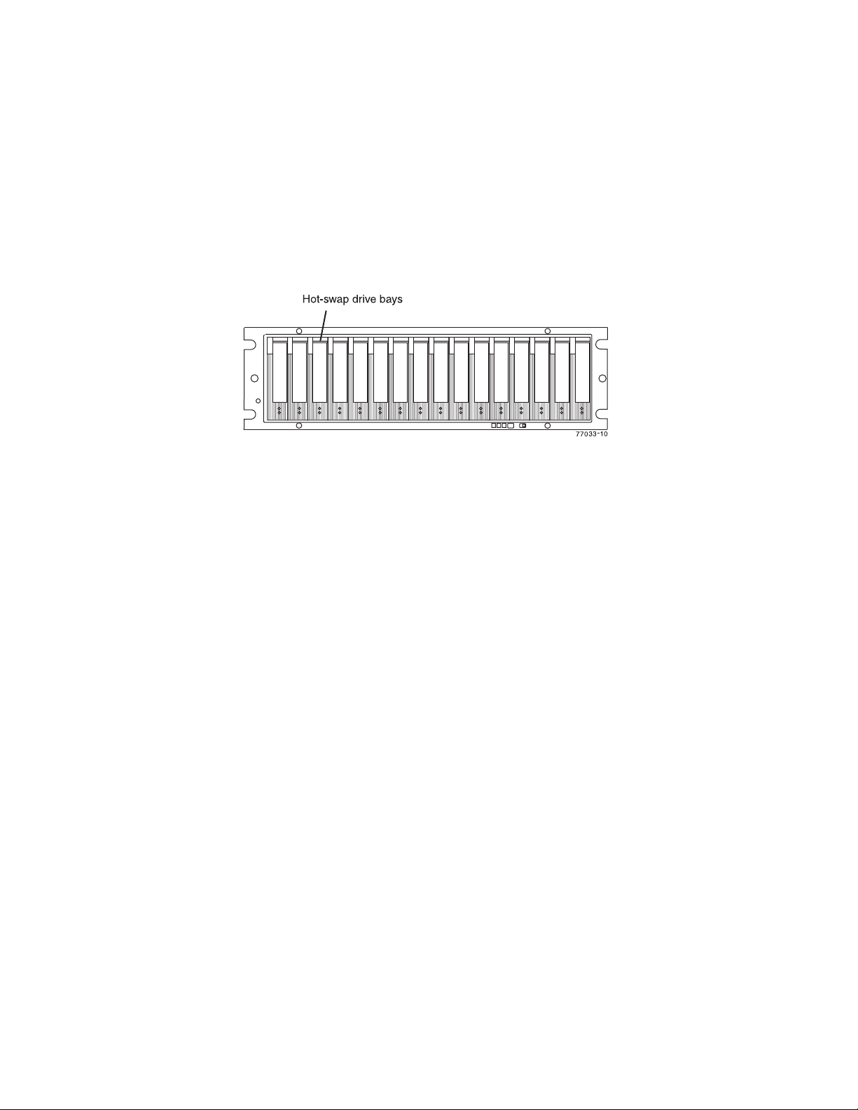
v Filter and filter retainer
The hot-swap features enable you to remove and replace 2 or 4 Gbps fibre channel
or SATA hard E-DDMs, power supply and fan units, and controllers without turning
off the storage subsystem. You can maintain the availability of your system while a
hot-swap device is removed, installed, or replaced.
Enhanced Disk Drive Modules (E-DDMs)
The hot-swap drive bays that are accessible from the front of your storage
subsystem are shown in Figure 1.
Figure 1. DS4700 Express hot-swap drive bays
The DS4700 Express supports both fibre channel (FC) and SATA E-DDMs
intermixed in the storage subsystem drive chassis. The DS4700 Express supports
up to sixteen 2 or 4 Gbps fibre channel (FC) or SATA E-DDMs.
SATA E-DDMs have an ATA translator card that converts the fibre channel protocol
interface of the DS4700 Express drive channel/loop into the hard drive SATA
protocol interface. It also provides dual paths to the SATA drive for drive CRU path
redundancy. Each drive, ATA translator card (also referred to as interposer card),
and carrier assembly are called SATA E-DDM CRUs. The fibre channel E-DDMs
consisted of the fibre channel and the carrier assembly (drive tray).
Install E-DDM CRUs in the 16 drive bays on the front of the storage subsystem
from the leftmost slot (slot 1) to the rightmost slot (slot 16). When a E-DDM is
installed, the drive and tray slot designation is set automatically. The hardware
addresses are based on the enclosure ID, which is set by the controller software,
and on the E-DDM's physical location in the storage subsystem.
The DS4700 Express Storage Subsystem drive channel operates at either 2 or 4
Gbps fibre channel interface speed. Ensure that the DS4700 Express enclosure
speed switch is set correctly for the 2 Gbps or 4 Gbps fibre channel E-DDM CRUs.
The DS4700 Express Storage Subsystem SATA E-DDM CRUs have an ATA
translator card that converts E-DDM 3 Gbps SATA drive interface protocol to either
2 Gbps or 4 Gbps fibre channel interface protocol. It is recommended to operate
these SATA E-DDMs at 4 Gbps fibre channel operating speed whenever the
configuration allows, for example, when no 2 Gbps fibre channel devices are in the
configuration. The Link Rate setting speed must be set accordingly. See “Verifying
the Link Rate setting ” on page 161 for more information. The enclosure speed of
the DS4000 Storage Subsystem must be the same as that of the storage expansion
enclosures connected to it.
There are no serviceable parts in an E-DDM CRU. If it fails, it must be replaced in
its entirety (E-DDM, ATA translator card, bezel, and tray). The DS4700 Express
drive tray is not interchangeable with the drive tray of other DS4000 storage
Chapter 1. Introduction 7
Page 40

Controllers
subsystems such as DS4100 or DS4300 storage subsystems. The DS4700 Express
E-DDM option CRUs are not interchangeable with those of the DS4200 Express
and EXP420. When replacing an E-DDM CRU, be sure to order and install the
correct E-DDM CRU. Using non-supported E-DDM options or FRUs will result in the
E-DDM being locked out by the DS4700 Express controller firmware and might also
damage the drive connector in the enclosure midplane.
Attention:
1. After you remove a E-DDM CRU, wait 70 seconds before replacing or reseating
the E-DDM CRU to allow it to properly spin down. Failure to do so may cause
undesired events.
2. Never hot-swap a E-DDM CRU when its associated green Activity LED is
flashing. Hot-swap a E-DDM CRU only when its associated amber Fault LED
lights is not flashing or when the E-DDM is inactive and its associated green
Activity LED lights is not flashing.
Note: If the E-DDM you want to remove is not in a failed or bypass state, always
use the Storage Manager client program either to place it in a failed state or
to place the array that is associated with the E-DDM (or E-DDMs) in an
offline state before you remove it from the enclosure.
The DS4700 Express has two hot-swappable and redundant RAID controllers. The
controllers are located at the back of the storage subsystem. The left controller is
labeled controller A, and the right controller is labeled controller B. One controller
will continue to operate if the other controller fails.
The controllers contain the storage subsystem control logic, interface ports, and
LEDs. The controller on model 70 has two fibre channel host ports and the
controller on model 72 has four fibre channel host ports that you could use to
connect the storage subsystem to the host server. In addition, each controller for
both DS4700 Express subsystem models 70 and 72 has two fibre channel drive
ports for connecting to the DS4000 storage expansion enclosures and two Ethernet
ports for DS4700 Express subsystem management purposes. See Figure 2 on page
10.
Although both controllers (A and B) are identical, they are seated in the DS4700
Express chassis in opposite orientations. See Figure 2 on page 10. If the controller
cannot fully be inserted in the controller bay, flip it 180 degrees and reinsert it. Do
not force fit because it may cause damage to the controller unit.
Connectors, switch, and enclosure ID
The controllers support fiber optic interfaces for both the host channel and drive
channel ports. The controllers also contain two Ethernet ports for storage
subsystem management purposes and a serial port that IBM Support uses to
perform problem recovery and troubleshooting procedures.
The default IP addresses for the Ethernet ports on controller A are 192.168.128.101
and 192.168.129.101. The default IP addresses for the Ethernet ports on controller
B are 192.168.128.102 and 192.168.129.102. The subnet mask for all cases are
255.255.255.0. See “Setting up IP addresses for DS4000 storage controllers” on
page 11 for more information.
The enclosure ID, comprised of two seven-segment numbers, is located on the
back of each controller next to the controller indicator lights. The two digits that
8 IBM System Storage DS4700 Express Storage Subsystem: Installation, User’s and Maintenance Guide
Page 41

comprise the enclosure ID are referred to as x10 and x1 digits. The enclosure ID
provides a unique identifier for each enclosure in the storage subsystem. The
storage management software automatically sets the enclosure ID number. You can
only change the enclosure ID setting through the DS4000 storage management
software. There are no switches on the DS4700 Express chassis to manually set
the enclosure ID. Both controller enclosure ID numbers will be identical under
normal operating conditions. The enclosure ID is set to a value of 85 from the
factory.
Storage expansion enclosures in a DS4000 storage subsystem must also have
unique enclosure IDs. In addition to having unique enclosure IDs for each storage
expansion enclosure (including the DS4000 storage subsystems with drives
installed) in the DS4000 storage subsystem configuration, ensure that the single
digit (x1) of the enclosure ID for every storage expansion enclosure in a redundant
drive channel/loop pair is unique.
If you do not set the single digit value of the enclosure IDs to be unique among
storage expansion enclosures (including the DS4000 storage subsystem with drives
installed) in a redundant drive channel/loop pair, then drive loop errors might be
randomly posted in the DS4000 subsystem Major Event Log (MEL) when you
intermix different types of storage expansion enclosures in a redundant drive loop
pair (such as an EXP100 with an EXP810). For example, with four enclosures
attached to a DS4500 in a redundant drive loop pair, the correct enclosure ID
settings should be x1, x2, x3, and x4 (where x can be any digits that can be set).
Examples of incorrect settings would be 11, 21, 31, 41; or 12, 22, 32 62. These
examples are incorrect because the x1 digits are the same in all enclosure IDs
(either 1 or 2).
If the enclosure IDs in your DS4000 subsystem configuration are not currently set to
have unique single digit (x1) values for the enclosures in the same redundant drive
channel/loop pair, make the changes to the enclosure IDs in the next maintenance
schedule if you have storage expansion enclosures with mechanical switches such
as EXP710s in the DS4000 configuration. This will prevent unnecessary downtime
when you add enclosures of different types (especially EXP810s) to the existing
enclosures in the redundant drive channel/loop pair. Storage expansion enclosures
and DS4000 storage subsystems with mechanical enclosure ID switches require
that you power cycle the configurations to activate the new enclosure ID settings.
The EXP810 storage expansion enclosures do not required you to power cycle the
DS4000 configuration to activate new enclosure ID settings.
Figure 2 on page 10 shows the controllers for DS4700 Express model 70. Figure 3
on page 10 shows the controllers for DS4700 Express model 72.
Chapter 1. Introduction 9
Page 42

7
6
345
1
ds470004
2
3
4
5 6
Figure 2. Back view; connectors, switch, ports, enclosure ID on model 70
Table 2. Description of Figure 2
Number Description
1 Controller A
2 Controller B
3 Host channels
4 Ethernet ports
5 Serial port
6 Dual-ported drive channel
7 Enclosure ID
7
3456
1
7
ds470016
3
4
5 6
Figure 3. Back view; connectors, switch, ports, enclosure ID on model 72
Table 3. Description of Figure 3
Number Description
1 Controller A
2 Controller B
3 Host channels
4 Ethernet ports
5 Serial port
6 Dual-ported drive channel
7 Enclosure ID
10 IBM System Storage DS4700 Express Storage Subsystem: Installation, User’s and Maintenance Guide
2
7
Page 43

Setting up IP addresses for DS4000 storage controllers
After you install DS4000 Storage Manager (as described in the DS4000 Storage
Manager Installation and Support Guide for your host operating system), complete
one of the following procedures to set up IP addresses:
v “Steps for setting up the DHCP/BOOTP server and network”
v “Steps for assigning static TCP/IP addresses to the DS4000 controllers”
Steps for setting up the DHCP/BOOTP server and network: To complete this
procedure, you must have the following components:
v A DHCP or BOOTP server
v A network management station (NMS) for Simple Network Management Protocol
(SNMP) traps
v A host that is connected to a storage subsystem through a fibre-channel I/O path
v A management station that is connected by an Ethernet cable to the storage
subsystem controllers
Note: You can avoid DHCP/BOOTP server and network tasks either by using the
default controller IP addresses, or by assigning static IP addresses to the
controller, as described in the next section.
Complete the following steps to set up the DHCP/BOOTP server and network:
1. Get the MAC address from each controller blade.
2. Complete whichever of the following steps is appropriate for your server:
v On a DHCP server, create a DHCP record for each of the MAC addresses.
Set the lease duration to the longest time possible.
v On a BOOTP server, edit the bootptab file to add in the entries that associate
the MAC address tab with the TCP/IP address.
3. Connect the DS4000 storage subsystem Ethernet ports to the network.
4. Boot the DS4000 storage subsystem.
The DHCP server automatically assigns new IP addresses to the controller Ethernet
port.
Steps for assigning static TCP/IP addresses to the DS4000 controllers: To
complete this procedure, you must have the following components:
v A host that is connected to a storage subsystem through a fibre-channel I/O path
v A management station that is connected by an Ethernet cable to the storage
subsystem controllers
Complete the following steps to assign static TCP/IP addresses to the DS4000
storage subsystem controllers, using default TCP/IP addresses that are assigned to
the DS4000 storage subsystem controllers during manufacturing:
1. Make a direct management connection to the DS4000 storage subsystem, using
the default TCP/IP addresses:
v Controller A: 192.168.128.101
v Controller B: 192.168.128.102
v Subnet Mask: 255.255.255.0
Note: For a DS4000 subsystem that has two Ethernet ports per controller, such
as the DS4200, DS4700 and DS4800, use the Ethernet port that is
labeled #1.
Chapter 1. Introduction 11
Page 44

2. Start the DS4000 Storage Manager client software. The Enterprise Management
window opens.
3. Add the DS4000 subsystem to the DS4000 Enterprise Management domain
using the default IP addresses.
4. In the Enterprise Management window, click on the name of the default storage
subsystem. The Subsystem Management window opens.
5. In the Subsystem Management window, right-click the controller icon and select
Change —> Network Configuration in the pull-down menu. The Change
Network Configuration window opens.
6. In the Change Network Configuration window, click on the Controller A and
Controller B tabs and type the new TCP/IP addresses in their appropriate fields.
Click OK.
7. Close the Subsystem Management window, wait at least five minutes, then
delete the default DS4000 storage subsystem entry in the Enterprise
Management window. The default DS4000 storage subsystem entry still
displays, but shows an “unresponsive” icon.
8. If applicable, change the IP address of the Ethernet port in the management
station to a value that is on the same TCP/IP subnet as the controller Ethernet
port IP addresses that you just assigned. Exit DS4000 Storage Manager, then
restart.
9. Add a new storage subsystem entry in the Enterprise Management window,
using the new assigned IP addresses.
Note: To manage storage subsystems through a firewall, configure the firewall to
open port 2463 to TCP data.
AC power supply and fan units
The DS4700 Express Storage Subsystem (models 70A, 70H, 72A, and 72H) has
two removable ac power supply and fan units. Each power supply and fan unit
contains one power supply and two fans. The four fans pull air through the drive
from front to back across the drives.
The fans provide redundant cooling, which means that if one of the fans in either
fan housing fails, the remaining fans continue to provide sufficient cooling to
operate the storage subsystem. The power supplies provide power to the internal
components by converting incoming ac voltage to dc voltage. If one power supply is
turned off or malfunctions, the other power supply maintains electrical power to the
storage subsystem. To preserve the optimal airflow, do not remove a failed power
supply and fan unit CRU from the DS4700 Express chassis until you are ready to
replace it with a new CRU.
Figure 4 on page 13 shows power supply and fan unit components for the DS4700
Express model 70 and Figure 5 on page 13 shows power supply and fan unit
components for DS4700 Express model 72.
Note: Although both power supply and fan units (left and right) are identical, they
are seated in the DS4700 Express chassis in opposite orientations. If the
power supply and fan unit cannot fully be inserted in the power supply and
fan unit bay, flip it 180 degree and reinsert it.
12 IBM System Storage DS4700 Express Storage Subsystem: Installation, User’s and Maintenance Guide
Page 45
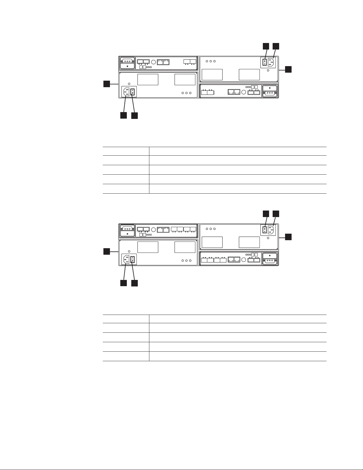
4
3
2
1
ds470040
3
4
Figure 4. Power supply and fan unit components for DS4700 Express model 70
Table 4. Description of Figure 4
Number Description
1 Power supply and fan unit A
2 Power supply and fan unit B
3 Power connector
4 Power switch
4
3
2
1
ds470041
3
4
Figure 5. Power supply and fan unit components for DS4700 Express model 72
Table 5. Description of Figure 5
Number Description
1 Power supply and fan unit A
2 Power supply and fan unit B
3 Power connector
4 Power switch
Figure 6 on page 14 shows a power supply and fan unit and the airflow through the
storage subsystem.
Chapter 1. Introduction 13
Page 46

Latch
Lever
Figure 6. Power supply and fan unit and airflow
DC power supply and fan units
The DS4700 Express Storage Subsystem (models 70S, 70T, 72S, and 72T) has
two removable dc power supply and fan units. Each dc power supply and fan unit
contains one dc power supply and two fans. The four fans pull air through the drive
from front to back across the drives.
The fans provide redundant cooling, which means that if one of the fans in either
fan housing fails, the remaining fans continue to provide sufficient cooling to
operate the storage subsystem. The power supplies provide power to the internal
components. If one power supply is turned off or malfunctions, the other power
supply maintains power to the storage subsystem. To preserve the optimal airflow,
do not remove a failed dc power supply and fan unit CRU from the DS4700
Express chassis until you are ready to replace it with a new CRU.
Figure 6 shows a power supply and fan unit and the airflow through the storage
subsystem.
Figure 7 on page 15 shows a side view of the dc power supply and fan units (1).
Note: Although both dc power supply and fan units (left and right) are identical,
they are seated in the DS4700 Express chassis in opposite orientations. If
the dc power supply and fan unit cannot fully be inserted in the dc power
supply and fan unit bay, flip it 180 degree and reinsert it.
14 IBM System Storage DS4700 Express Storage Subsystem: Installation, User’s and Maintenance Guide
Page 47
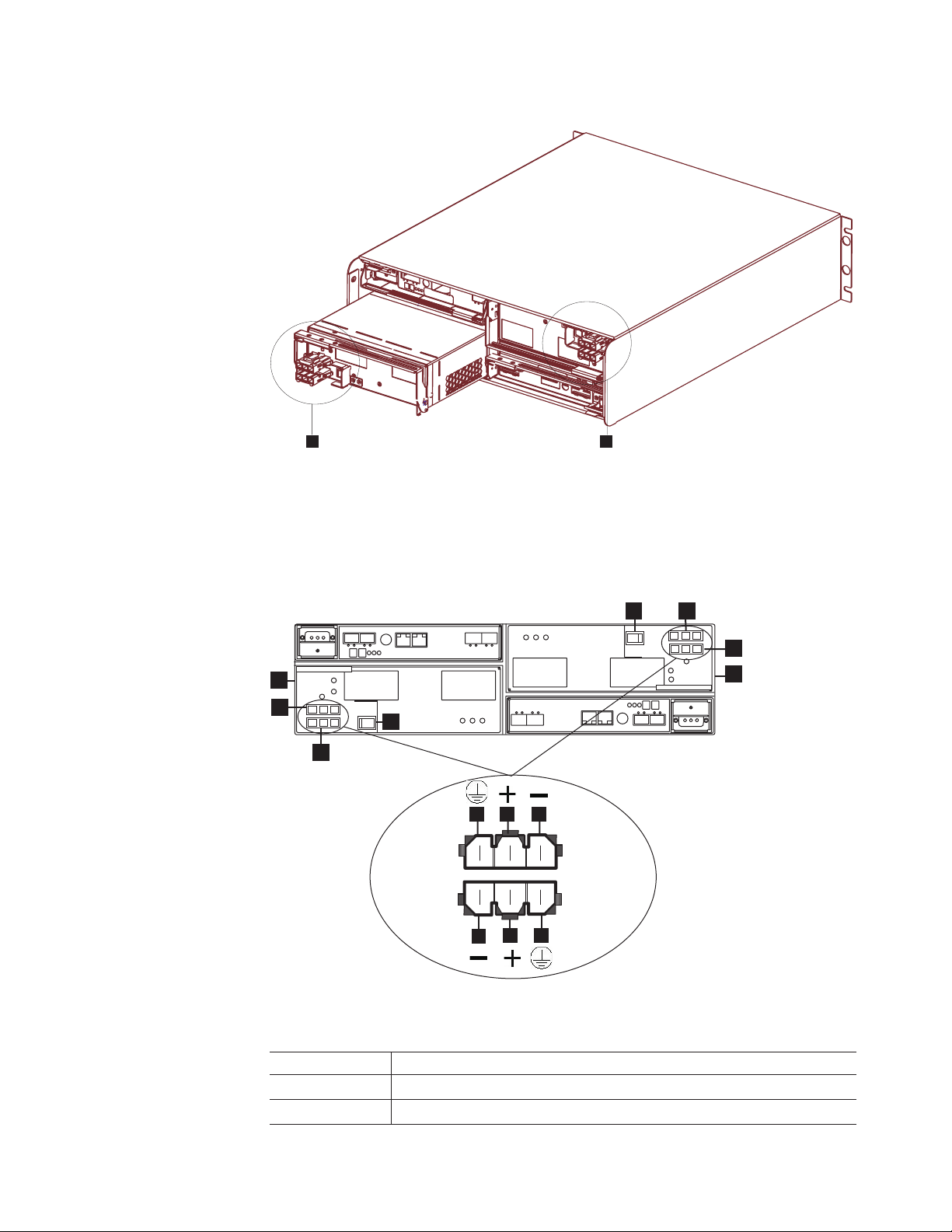
ds470070
1 1
Figure 7. DC power supply and fan unit
Figure 8 shows the dc power supply and fan unit components for the DS4700
Express model 70 and Figure 9 on page 16 shows the dc power supply and fan unit
components for the DS4700 Express model 72.
4
7
6
1
5
2
4
ds470074
3
10
8
8
9
109
Figure 8. DC power supply and fan unit for DS4700 Express model 70
Table 6. DC power supply and fan unit description for DS4700 Express model 70
Number Description
1 DC power supply and fan unit A
2 DC power connector A1
1
Chapter 1. Introduction 15
Page 48

Table 6. DC power supply and fan unit description for DS4700 Express model 70 (continued)
Number Description
3 DC power connector A2
1
4 DC power switch
5 DC power supply and fan unit B
6 DC power connector B1
7 DC power connector B2
2
2
8 Pin 1: -48 V dc
9 Pin 2: POS RTN
10 Pin 3: GND
Notes:
1. The A1 and A2 dc connectors are keyed so that the dc cables are connected to the A1
and A2 connectors in only one way and in opposite orientation from each other. If the dc
cable does not fit the dc connector, flip it 180 degrees and try again. Do not force fit
because you might damage the connectors and short out the power supply.
2. The B1 and B2 dc connectors are keyed so that the dc cables are connected to the B1
and B2 connectors in only one way and in opposite orientation from each other. If the dc
cable does not fit the dc connector, flip it 180 degrees and try again. Do not force fit
because you might damage the connectors and short out the power supply.
4
7
1
2
4
3
10
8
8
9
109
Figure 9. DC power supply and fan unit for DS4700 Express model 72
6
5
ds470075
Table 7. DC power supply and fan unit description for DS4700 Express model 72
Number Description
1 DC power supply and fan unit A
2 DC power connector A1
1
16 IBM System Storage DS4700 Express Storage Subsystem: Installation, User’s and Maintenance Guide
Page 49

Table 7. DC power supply and fan unit description for DS4700 Express model 72 (continued)
Number Description
3 DC power connector A2
1
4 DC power switch
5 DC power supply and fan unit B
6 DC power connector B1
7 DC power connector B2
2
2
8 Pin 1: -48 V dc
9 Pin 2: POS RTN
10 Pin 3: GND
Notes:
1. The A1 and A2 dc connectors are keyed so that the dc cables are connected to the A1
and A2 connectors in only one way and in opposite orientation from each other. If the dc
cable does not fit the dc connector, flip it 180 degrees and try again. Do not force fit
because you might damage the connectors and short out the power supply.
2. The B1 and B2 dc connectors are keyed so that the dc cables are connected to the B1
and B2 connectors in only one way and in opposite orientation from each other. If the dc
cable does not fit the dc connector, flip it 180 degrees and try again. Do not force fit
because you might damage the connectors and short out the power supply.
Battery units
Each controller also contains a rechargeable battery unit that maintains data in the
cache in the event of a power failure.
Figure 10 on page 18 shows how the battery unit slides into the battery backup slot
in controller A CRU.
Chapter 1. Introduction 17
Page 50
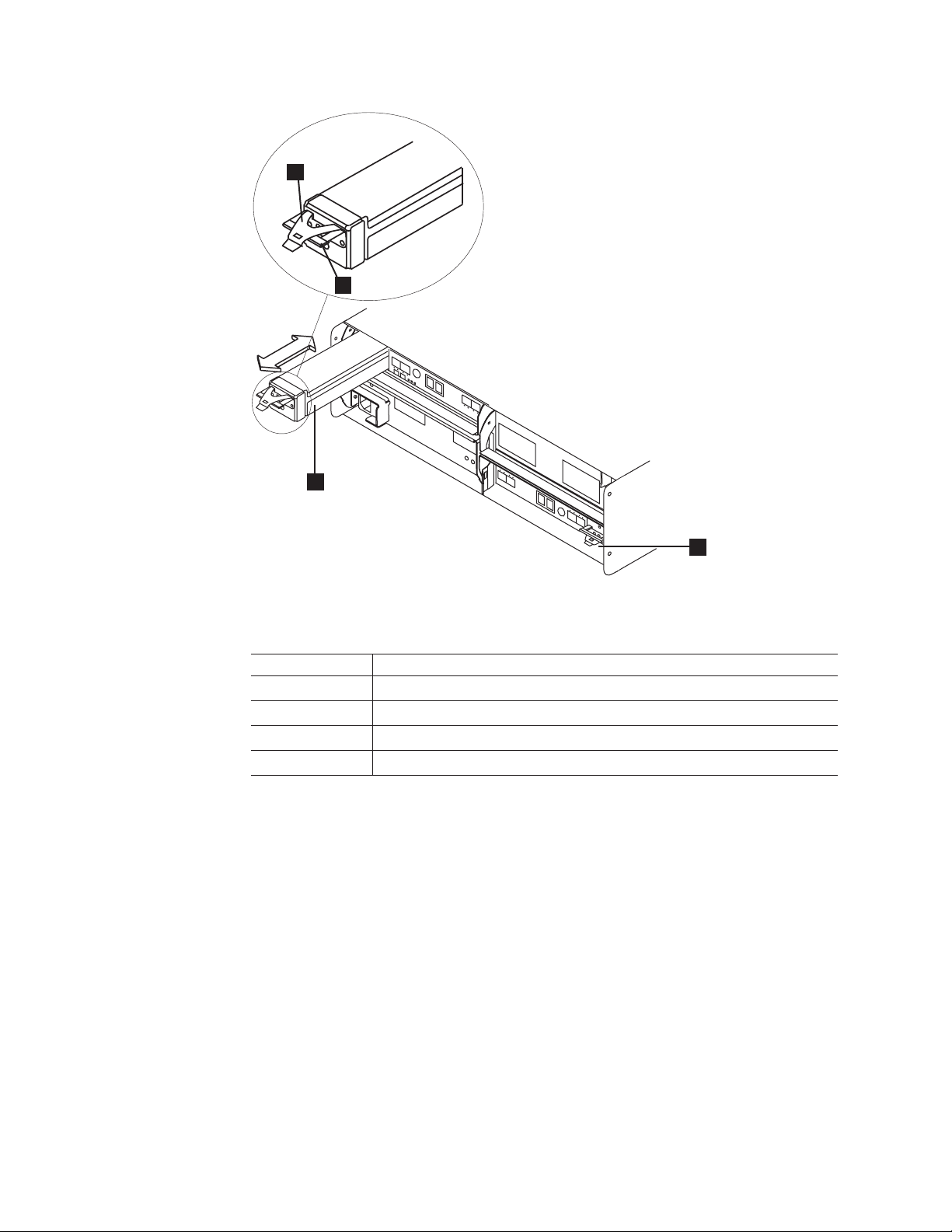
3
4
1
Figure 10. Battery unit
2
ds470012
Table 8. Description of Figure 10
Number Description
1 Controller A cache backup battery unit
2 Controller B cache backup battery unit
3 Latch
4 Pull handle
The battery unit provides backup power to each controller's cache memory. Each
battery unit contains a sealed, rechargeable lithium ion battery. The battery unit can
maintain data in the cache for three days.
The battery chargers in the power supply and fan units perform a battery test when
the storage subsystem is started and on a regularly scheduled interval thereafter.
Data caching starts after the battery completes its battery tests.
The battery unit is hot-swappable. You can remove the battery unit for servicing and
then reinsert it while the DS4700 Express continues to perform I/O operations.
However, write I/O caching is disabled when the battery is in a failed state. Replace
the failed battery as soon as possible to minimize the time that the write IO caching
is disabled.
Information about the condition of the battery unit is conveyed by indicator LEDs on
the front of battery unit. (“Battery unit LEDs” on page 128 identifies the indicator
LEDs on the battery unit and explains the conditions that each LED indicates.)
18 IBM System Storage DS4700 Express Storage Subsystem: Installation, User’s and Maintenance Guide
Page 51
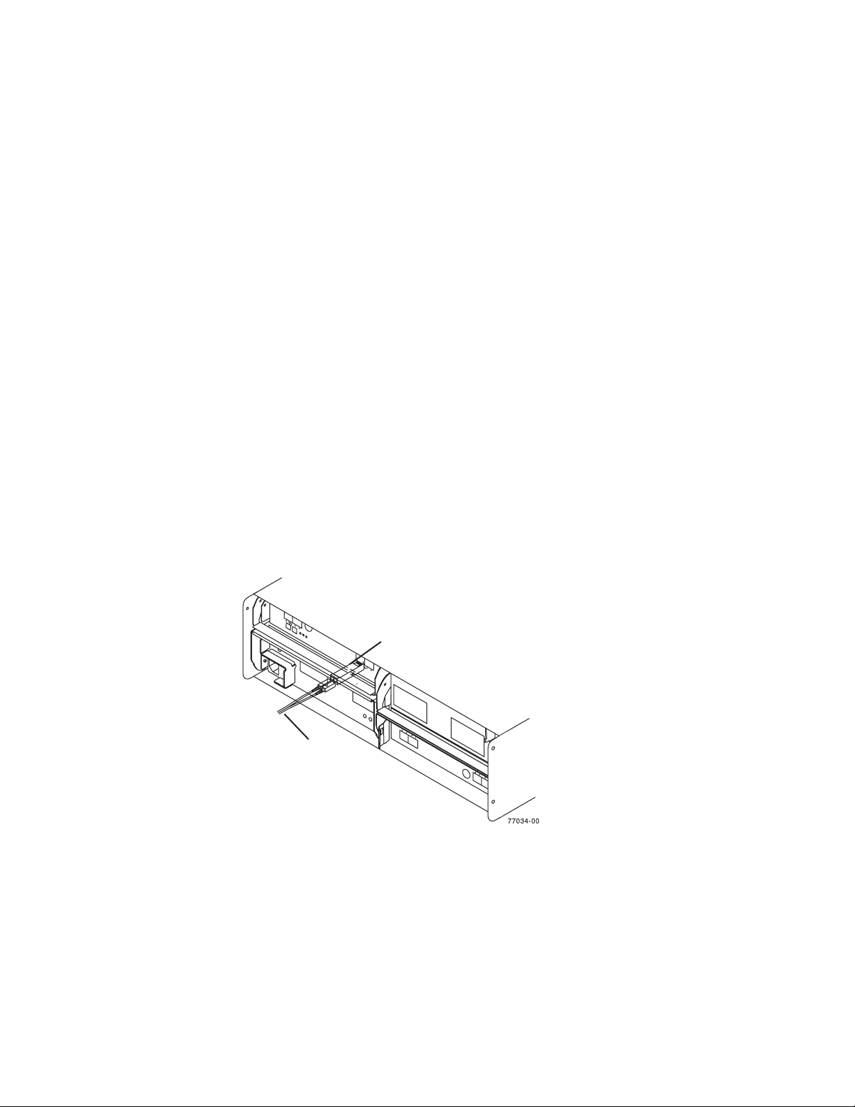
SFP modules
The storage subsystem supports a fiber optic interface for host and storage
expansion enclosure connections. You must install a Small Form-factor Pluggable
(SFP) module in each interface connector on the controller where a fibre optic cable
is to be installed. Do not install an SFP in any port that will not have a fibre optic
cable attached. Additionally, it is recommended that you remove any SFP from any
port that does not have fibre optic cables attached.
The DS4700 Express Storage Subsystem host ports support 1, 2 and 4 Gbps fibre
channel speeds. The DS4700 Express Storage Subsystem drive ports support only
2 and 4 Gbps fibre channel speeds.
Attention: The maximum operating speed of the fibre channel port is determined
by two factors: the speed of the SFP module that is installed and the speed of the
fibre channel connection. For example, a 2-Gbps SFP that is plugged into a
4-Gbps-capable port will limit the speed of that port to a maximum of 2 Gbps.
Conversely, a 4-Gbps SFP that is plugged into a 2-Gbps-capable port will limit the
speed of the port to a maximum of 2 Gbps. Carefully check the SFP's IBM part
number, option number, and FRU part number to identify its speed. There are no
physical features that distinguish a 4 Gbps from a 2 Gbps SFP.
Figure 11 shows an example of SFP module with fiber optic cable.
Note: The SFP module and the fibre optic cable shown are for illustrative purposes
only. The actual SFP module and the fibre optic cable shape may look
different from the figure shown.
Telco bezel
SFP
Module
Fiber-optic
cable
Figure 11. SFP module and fiber optic cable
The DS4700 Express Storage Subsystem can be ordered with a Telco bezel. The
Telco bezel also contains a filter and filter retainer. The replaceable filter is fitted
inside the Telco bezel and limits impurities, dust, air particles and other external
contaminants from adversely impacting the chassis, electronic CRUs, and hard
drive operational effectiveness. IBM recommends that you replace the filter every
three months or sooner, depending on your environment. Inspect the filter
periodically and replace it as required.
Chapter 1. Introduction 19
Page 52
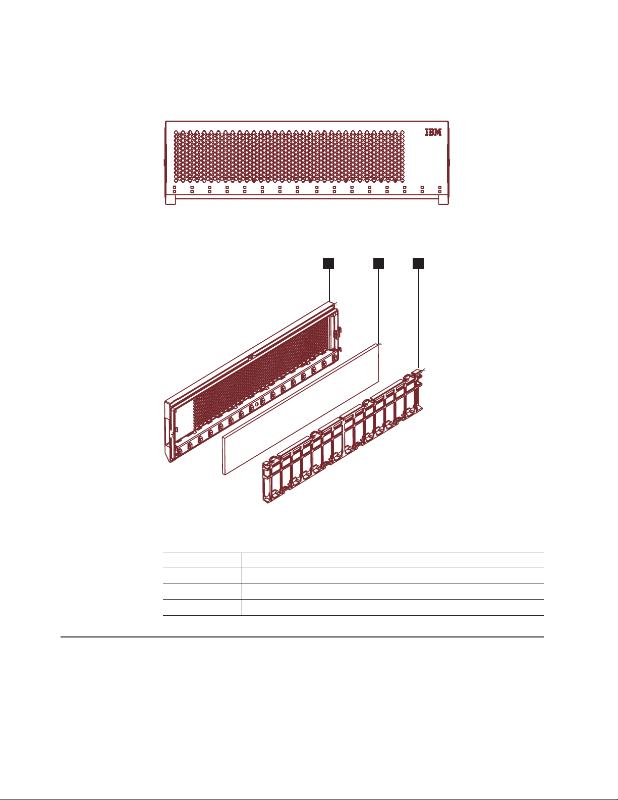
Figure 12 shows a front view of the bezel. Figure 13 shows a side view of the
bezel, filter, and filter retainer.
ds470065
Figure 12. Bezel
Figure 13. Filter and filter retainer
Table 9. Filter and filter retainer description
Number Description
1 Bezel
2 Filter
3 Filter retainer
2
31
ds470066
Software and hardware compatibility and upgrades
The latest DS4000 controller firmware and NVSRAM, the storage expansion
enclosure drive enclosure ESM firmware, and fibre channel and SATA drive CRUs
firmware must be installed to ensure optimal functionality, manageability, and
reliability.
20 IBM System Storage DS4700 Express Storage Subsystem: Installation, User’s and Maintenance Guide
Page 53

Unless stated otherwise, you can find the latest DS4000 publications, firmware, and
host software at the IBM DS4000 System Storage Support Web site:
www.ibm.com/systems/support/storage/disk
Software and firmware support code upgrades
To enable support for the DS4700 Express, you must ensure that your system's
software and firmware are the correct versions. To find the latest DS4000 Storage
Manager software, storage subsystem controller firmware, ESM, and NVSRAM
firmware, check the firmware readme files. See “Finding DS4000 readme files” on
page xxvii to learn how to access the readme files on the Web.
See the IBM System Storage DS4000 Storage Manager Installation and Host
Support Guide for your operating system for instructions that describe how to install
the DS4000 controller firmware and Storage Manager host software.
Note: For the latest information about supported servers and operating systems,
refer to the interoperability matrix at this Web site:
www-1.ibm.com/servers/storage/disk/ds4000/interop-matrix.html
Determining firmware levels
There are two different methods to determine the DS4000 storage subsystem and
firmware versions. Each method uses the DS4000 Storage Manager client that
manages the DS4000 storage subsystem.
Method One:
Go to the Subsystem Management window and select View → Storage Subsystem
Profile. When the Storage Subsystem Profile window opens, select the All tab and
scroll through the Profile For Storage Subsystem list to locate the following
information.
Note: The Profile For Storage Subsystem list contains all the profile information for
the entire subsystem. Therefore, it may be necessary to scroll through a
large amount of information to locate the firmware version numbers.
DS4000 Storage Server
v NVSRAM version
v Appware version
v Bootware version
Drives
v Firmware version
v ATA translator card firmware version (SATA E-DDMs only)
Note: The ATA translator card firmware and drive firmware are typically
packaged together as a single drive firmware upgrade file.
ESM
v ESM card firmware version
Method Two:
Complete the appropriate procedure to obtain the specified firmware version.
Chapter 1. Introduction 21
Page 54

Specifications
To obtain the controller firmware version:
Right-click the Controller icon in the Physical View pane of the Subsystem
Management window and select Properties. The Controller Enclosure
properties window opens and displays the properties for that controller.
You must perform this step for each individual controller.
To obtain the drive firmware (and ATA translator card firmware) version:
Right-click the Drive icon in the Physical View pane of the Subsystem
Management window and select Properties. The Drive Properties window
opens and displays the properties for that drive.
You must perform this step for each individual drive.
To obtain the ESM and drive enclosure component firmware versions:
1. In the Physical View pane of the Subsystem Management window, click
the Drive Enclosure Component icon, which is the icon furthest to the
right. The Drive Enclosure Component Information window opens.
2. Click the ESM icon in the left pane. The ESM information displays in the
right pane of the Drive Enclosure Component Information window.
3. Locate the firmware version of each ESM in the drive enclosure.
This section provides site specifications for the DS4700 Express Storage
Subsystem. Before installing, you must either verify that your planned installation
site meets these requirements, or prepare the site so that it does meet these
requirements. Preparations might involve meeting area requirements, environmental
requirements, and electrical requirements for DS4700 Express Storage Subsystem
installation, service, and operation.
Area requirements
The floor space at the installation site must provide enough strength to support the
weight of the storage subsystem and associated equipment; sufficient space to
install, operate, and service the storage subsystem; and sufficient ventilation to
provide a free flow of air to the unit.
Dimensions
Figure 14 on page 23 shows the dimensions of the DS4700 Express, which
conforms to the 19-inch rack standard.
22 IBM System Storage DS4700 Express Storage Subsystem: Installation, User’s and Maintenance Guide
Page 55

44.70 cm (17.60 in.)
12.95 cm (5.1 in.)
48.26 cm (19.00 in.)
77027-03
57.15 cm (22.5 in.)
Figure 14. DS4700 Express dimensions
Weight
The total weight of the storage subsystem depends on the number of components
installed. Table 10 lists the maximum, empty, and shipping weights for the storage
subsystem in different configurations. Table 11 lists the weight of each component.
Table 10. DS4700 Express weights
Weight
Unit
Maximum
1
DS4700 Express 40 kg (88 lb) 16.4 kg (36.1 lb) 52.2 kg (115.0 lb)
1
Chassis with all CRUs and 16 drives.
2
Chassis without CRUs and drives but with front cage frame and midplane.
Table 11. DS4700 Express component weights
Unit Weight
Drive 0.75 kg (1.65 lb)
Power supply and fan unit 3.60 kg (7.95 lb)
Controller (including cache battery backup
unit)
Battery unit 0.9 kg (2 lb)
2
Empty
2.8 kg (6.1 lb)
Shipping
Shipping dimensions
Table 12 lists shipping carton dimensions. The height shown includes the height of
the pallet.
Table 12. DS4700 Express shipping carton dimensions
Height Width Depth
45.7 cm (18.0 in.) 62.6 cm (24.5 in.) 80.7 cm (31.75 in.)
Chapter 1. Introduction 23
Page 56

Environmental requirements and specifications
This section describes the environmental requirements and specifications for the
DS4700 Express Storage Subsystem, including temperature and humidity, altitude,
airflow and heat dissipation, shock and vibration requirements, and acoustic noise
levels.
Temperature and humidity
Table 13 lists the acceptable temperature and humidity ranges for the DS4700
Express Storage Subsystem when in storage or in transit. Table 14 lists temperature
and humidity ranges for the storage subsystem in typical Information Technology
(IT) or office environments. Table 15 lists temperature and humidity ranges for the
storage subsystem in a Telco/NEBS-3 compliant environment.
Note: Substantial deviations from the suggested operating range, in either
direction, if sustained for extended periods of time, will expose the unit to
greater risk of failure from external causes.
Important: The recommended operating environment air temperature is 22° C (72°
F) or lower.
Table 13. Temperature and humidity requirements for storage subsystem when in storage or
in transit
Condition Parameter Requirement
Temperature Storage range -10° - 65° C (14° - 149° F)
Maximum rate of change 15° C (27° F) per hour
Transit range -40° C to 65° C (-40° F to
Maximum rate of change 20° C (36° F) per hour
Relative humidity (no
condensation)
Storage range 8% to 90%
Transit range 5% to 95%
Maximum dew point 26° C (79° F)
Maximum gradient 10% per hour
149° F)
Table 14. Temperature and humidity requirements for storage subsystem in a typical
Information Technology (IT) or office environment
Condition Parameter Requirement
Temperature Operating range 10° - 35° C (50° - 95° F)
Maximum rate of change 10° C (18° F) per hour
Relative humidity (no
condensation)
Table 15. Temperature and humidity requirements for storage subsystem in a Telco/NEBS-3
compliant environment
Condition Parameter Requirement
Temperature
1
Operating range 8% to 80%
Operating range 5° - 40° C (41° - 104° F)
Short-term
Maximum rate of change 30° C (54° F) per hour
2
-5° - 50° C (23° - 122° F)
24 IBM System Storage DS4700 Express Storage Subsystem: Installation, User’s and Maintenance Guide
Page 57

Table 15. Temperature and humidity requirements for storage subsystem in a Telco/NEBS-3
compliant environment (continued)
Condition Parameter Requirement
1
Relative humidity
condensation)
Notes:
1. In a Telco/NEBS-3 compliant environment, conditions are measured at a location 1.5 m
(59 in.) above the floor and 400 mm (15.8 in.) in front of the equipment.
2. Short-term refers to a period of not more than 96 consecutive hours and a total of not
more than 15 days in one year. (This refers to a total of 360 hours in any given year, but
no more than 15 occurrences during that one-year period.)
(no
Operating range 5% to 85%
Short-term
2
5% to 90% (not to exceed
0.024 kg water/kg of dry air)
Altitude
Table 16 lists the acceptable altitudes for operating, storing, and shipping the
DS4700 Express.
Table 16. DS4700 Express altitude ranges
Environment Altitude
Operating 30.5 m (100 ft.) below sea level to 3000 m
(9842 ft.) above sea level
Storage 30.5 m (100 ft.) below sea level to 3000 m
(9842 ft.) above sea level
Transit 30.5 m (100 ft.) below sea level to 12,000 m
(40,000 ft.) above sea level
Airflow and heat dissipation
Figure 15 shows the intended airflow for the DS4700 Express. Allow at least 30
inches in front of the storage subsystem and at least 24 inches behind the storage
subsystem for service clearance, proper ventilation, and heat dissipation.
77027-02
Figure 15. DS4700 Express airflow
Table 17 on page 26 lists the KVA, watts, and Btu calculations. These values
assume the power supplies have a 73 percent efficiency and a power factor of 0.99.
Chapter 1. Introduction 25
Page 58

These tabulated power and heat dissipation values are typical for the storage
subsystem. Maximum configuration units are typically operated at higher data rates,
have larger random access memory (RAM) capacities, or have different host
interface boards.
Table 17. DS4700 Express power and heat dissipation
Parameter KVA Watts (ac) Btu per hour
DS4700 Express 0.454 443 1516
Shock and vibration requirements
Operational shock and operational vibration requirements are shown in this section.
Operational Shock: The DS4700 Express will be able to withstand the following
shock. Subjecting the equipment to a single shock pulse with the following
characteristics will simulate this level of shock:
v Velocity change = 20 inches per second
v Wave form = Triangular, 10g @3.75 ms
Operational Vibration (Random): While in its normal operating position, the
DS4700 Express will continue operating when subjected to a random vibration test
using the criteria shown in Table 18. This test uses the indicated spectral power
density for 30 minutes in each of the three axes.
Table 18. Random vibration power spectral density
Hz 5 17 45 48 62 65 150 200 500
2
/Hz 2.0x10⁻⁷-72.2x10
g
-5
2.2x10
-5
2.2x10
-5
2.2x10
-5
2.2x10
-5
2.2x10
-5
2.2x10
-5
2.2x10
-5
Acoustic noise
Table 19 lists the maximum sound levels emitted by the storage subsystem.
Table 19. DS4700 Express sound levels
Measurement Level
Sound power (normal operation) 6.8 bels
Sound pressure (normal operation) 68 dBA
These levels are measured in controlled acoustical environments according to ISO
7779 and are reported in accordance with ISO 9296. The declared sound power
levels indicate an upper limit, below which a large portion of machines operate.
Sound pressure levels in your location might exceed the average 1-meter values
stated because of room reflections and other nearby noise.
Electrical requirements
This section provides information regarding site power and wiring, storage
subsystem ac power requirements, dc power requirements and power cord routing
instructions.
Consider the following information when preparing the installation site:
v Protective ground – Site wiring must include a protective ground connection to
the ac power source.
Note: Protective ground is also known as safety ground or chassis ground.
26 IBM System Storage DS4700 Express Storage Subsystem: Installation, User’s and Maintenance Guide
Page 59

v Circuit overloading – Power circuits and associated circuit breakers must provide
sufficient power and overload protection. To prevent possible damage to the unit,
isolate its power source from large switching loads (such as air conditioning
motors, elevator motors, and factory loads).
v Power failures – If a total power failure occurs, the unit automatically performs a
power-up recovery sequence without operator intervention after power is
restored.
Table 20. DS4700 Express ac power requirements
Low Range High Range
Nominal Voltage 90 to 136 VAC 198 to 264 VAC
Frequency (Hertz) 50 to 60 Hz 50 to 60 Hz
Idle Current 3.86 A
Maximum Operating Current 4 A/4.54 A
Maximum Surge Current 5.04 A
a.
Typical voltage: 115 V ac, 60 Hz, assumes 72% power-supply efficiency and 0.99 power
a
ac
a
factor
b.
Typical voltage: 230 V ac, 60 Hz, assumes 72% power-supply efficiency and 0.99 power
factor
c.
The higher number in this range applies when all of the drives are placed in Selfseek
mode.
b
2.05 A
2.12 A/2.41 A
b
2.67 A
bc
Table 21. DS4700 Express dc power requirements
Requirement
Operating Voltage -42 V to -60 V
Nominal Voltage -48 V
Idle Current 11.8 A
Maximum Operating Current 15.8 A
Maximum Surge Current 16 A
Power and site wiring requirements for models with ac power supply and fan units
The storage subsystem uses wide-ranging redundant power supplies that
automatically accommodate voltages to the ac power source. The ac power
supplies operate within the ranges specified in Table 20. The ac power supplies
meet standard voltage requirements for both domestic (inside USA) and
international (outside USA) operation. They use standard industrial wiring with
line-to-neutral or line-to-line power connections.
The agency ratings for the DS4700 Express Storage Subsystem (ac models) are 6
amps at 100 VAC and 2.5 amps at 240 VAC. These are the overall maximum
operating currents for the DS4700 Express Storage Subsystem with ac power
supply and fan unit CRUs.
AC power recovery: After a total ac power failure, after normal power is restored,
the storage subsystem performs power-up recovery procedures automatically
without operator intervention.
Power cords and receptacles: The storage subsystem ships with two jumper
cords used to connect to the rack PDU. You must purchase the power cords that
Chapter 1. Introduction 27
Page 60

are appropriate for use in a typical outlet in the destination country. See
Appendix C, “Power cords,” on page 199 for more information.
Power and site wiring requirements for models with dc power supply and fan units
The storage subsystem uses wide-ranging redundant power supplies that
automatically accommodate voltages to the dc power source. The dc power
supplies operate within the ranges specified in Table 21 on page 27. The dc power
supplies require a reliably grounded safety extra low voltage SELV source and an
approved and rated disconnect device for the -48V line.
The agency rating for the DS4700 Express Storage Subsystem (dc models) is 16
amps at -42V to -60V dc. This is the overall maximum operating current for the
DS4700 Express Storage Subsystem with dc power supply and fan unit CRUs.
DC power recovery: After a total dc power failure, after normal power is restored,
the storage subsystem performs power-up recovery procedures automatically
without operator intervention.
Power cords and receptacles: The storage subsystem ships with two dc power
jumper cables used to connect to the dc power source. See “Cabling the dc power
supply for dc models” on page 111 for more information.
Heat output, airflow, and cooling
See “Airflow and heat dissipation” on page 25 for heat output, airflow, and cooling
specifications.
Note: In general, disk subsystem reliability tends to decrease as the ambient
temperature of the environment in which it is being used increases. The
ambient temperature in the immediate area of the disk enclosure unit should
be kept near 22° C (72° F), or lower, to provide better reliability.
When racks that contain many storage subsystems are to be installed together, the
following requirements must be met to ensure that the storage subsystems are
adequately cooled:
v Air enters at the front of the rack and leaves at the back. To prevent the air that
is leaving the rack from entering the intake of another piece of equipment, you
must position the racks in alternate rows, back-to-back and front-to-front. This
arrangement is known as “cold aisle/hot aisle” and is shown in Figure 16 on page
29.
v Where racks are in rows, each rack must touch the rack that is next to it to
reduce the amount of hot air that can flow around from the back of the rack into
the intakes of the storage expansion enclosures that are in that rack. You should
use Suite Attach Kits to completely seal any gaps that remain between the racks.
For details about Suite Attach Kits, contact your marketing representative.
v Where racks are in rows front-to-front or back-to-back, a gap of at least 1220 mm
(48 in.) must separate the rows across the cold aisle.
v To ensure correct airflow in each rack, the rack filler plates must be installed in
unused positions. Also, all the gaps in the front of the racks must be sealed,
including the gaps between the storage subsystems.
28 IBM System Storage DS4700 Express Storage Subsystem: Installation, User’s and Maintenance Guide
Page 61

T42 racks
back
front
1220 mm cold
aisle width
Air
Cold aisle
front
T42 racks
back
conditioner
Hot aisle
back
T42 racks
front
Airflow
Figure 16. Example of cold aisle/hot aisle rack configuration
Perforated tiles
or gratings
2440 mm between
center lines of hot
and cold aisle
Chapter 1. Introduction 29
Page 62

30 IBM System Storage DS4700 Express Storage Subsystem: Installation, User’s and Maintenance Guide
Page 63

Chapter 2. Installing the storage subsystem
This chapter provides the information that you need to install the storage subsystem
into a rack cabinet.
Before you begin the installation, review the safety information in “Safety” on page
xv.
“Installation overview” provides an overview of the entire storage subsystem
installation process. Read this overview before you begin the installation.
Installation overview
Statement 4:
≥ 18 kg (39.7 lb) ≥ 32 kg (70.5 lb) ≥ 55 kg (121.2 lb)
CAUTION:
Use safe practices when lifting.
Attention: A fully configured DS4700 Express weighs up to 40 kg (88 lb). At least
two other people should help you lift the DS4700 Express from the shipping box. If
desired, open the sides of the shipping box and remove the CRUs from the DS4700
Express before you lift it from the shipping box in order to lighten the storage
subsystem. See “Removing the CRUs” on page 40.
The following steps summarize the DS4700 Express installation process. Each step
below is detailed in this chapter or next two chapters, Chapter 3, “Cabling the
storage subsystem,” on page 55 and Chapter 4, “Operating the storage subsystem,”
on page 117.
1. Review the preparation recommendations. See “Preparing for installation” on
page 34.
2. Prepare the installation site. See “Preparing the site” on page 35.
3. Prepare the rack cabinet. See “Preparing the rack cabinet” on page 36.
4. Fold down and open the sides of the shipping box. Without removing the
DS4700 Express from box, you can remove the DS4700 Express rack
mounting rails and hardware from the box. The DS4700 Express rack
mounting rails and hardware are placed on the bottom of the shipping box
(under the DS4700 Express Storage Subsystem). Install the support rails in the
rack cabinet. See “Installing the support rails” on page 36.
© Copyright IBM Corp. 2010 31
Page 64

5. Before removing the DS4700 Express from the shipping box, remove the
components from the DS4700 Express chassis to lighten the unit. See
“Removing the CRUs” on page 40.
6. Record the serial number, machine type and model number, and RAID
controller MAC addresses for your DS4700 Express Storage Subsystem in
Appendix A, “Records,” on page 191.
The serial number, machine type, and model number are located on the left
edge of the front unit as shown in Figure 17.
Serial number
Machine type
Model number
Figure 17. Example of DS4700 Express serial number, machine type, and model number
location
The MAC addresses are located near the Ethernet ports on each RAID
controller.
7. Install and secure the DS4700 Express chassis in the rack cabinet. See
“Installing the DS4700 Express into a rack on the support rails” on page 46.
8. If needed, replace the components in the installed DS4700 Express chassis.
See “Replacing the components” on page 48.
9. Install in the rack cabinet the DS4000 storage expansion enclosure or
enclosures you will cable to the DS4700 Express. Follow the instructions in the
Installation, User’s, and Maintenance Guide for your DS4000 storage
expansion enclosure to set up and mount the storage expansion enclosures.
ds470042
Attention
Before powering on the DS4700 Express Storage Subsystem, it must be
populated with at least two E-DDMs. If at least two E-DDMs are not
installed in each attached storage expansion enclosure or DS4700
Express Storage Subsystem, when you power on the DS4700 Express
and its attached storage expansion enclosures, your standard storage
partition key might be lost and must be regenerated using instructions on
the IBM DS4000 Solutions and Premium Features Web site:
https://www-912.ibm.com/PremiumFeatures/
In addition, the resulting insufficient load to the enclosure power supplies
might cause them to intermittently appear as failed, falsely indicating the
power supplies are bad. All E-DDMs in the DS4700 Express Storage
Subsystem and the connected storage expansion enclosure or
enclosures must contain no prior configuration data.
10. Use SFP modules and fibre channel cables to cable the DS4700 Express to
the DS4000 storage expansion enclosure or enclosures. See “Connecting
storage expansion enclosures to the DS4700 Express” on page 68.
11. Set the enclosure IDs for all storage expansion enclosures in the configuration.
See “Storage expansion enclosure settings” on page 97.
32 IBM System Storage DS4700 Express Storage Subsystem: Installation, User’s and Maintenance Guide
Page 65

Note: Perform this step if the attached storage expansion enclosures are
EXP710s or EXP100s only. The EXP810 storage expansion enclosure
IDs are automatically set by the controllers to be unique when they are
cabled together.
12. Perform one of the following cabling tasks to enable management of the
DS4700 Express configuration:
v If you are using out-of-band management, cable the DS4700 Express
Ethernet ports to either the management workstation or the host.
v If you are using in-band management, cable the DS4700 Express host
channels to the fibre channel host bus adapters (HBAs) in either the hosts
or the fibre channel switch that connects to the host HBAs. See “Connecting
hosts to the DS4700 Express” on page 104.
13. Connect the power cables for the DS4700 Express. See “Cabling the ac power
supply for ac models” on page 111.
14. Power on the attached storage expansion enclosure and the DS4700 Express
Storage Subsystem using the procedure described in “Powering on the storage
subsystem” on page 119.
15. Install the DS4000 Storage Manager host software on the management
workstation (for out-of-band management) or on the host (for in-band
management). Refer to the IBM System Storage DS4000 Storage Manager
Version 10 Installation and Host Support Guide for the appropriate operating
system for instructions on how to install the DS4000 Storage Manager host
software.
16. Use the DS4000 Storage Manager host software to verify the configuration.
17. Review and perform the procedures described in “Performing the DS4000
Health Check process” on page 117.
Handling static-sensitive devices
Attention: Static electricity can damage electronic devices and your system. To
avoid damage, keep static-sensitive devices in their static-protective packages until
you are ready to install them.
To reduce the possibility of electrostatic discharge (ESD), observe the following
precautions:
v Limit your movement. Movement can cause static electricity to build up around
you.
v Handle the device carefully, holding it by its edges or its frame.
v Do not touch solder joints, pins, or exposed printed circuitry.
v Do not leave the device where others can handle and possibly damage the
device.
v While the device is still in its static-protective package, touch it to an unpainted
metal part of the system unit for at least two seconds. This drains static electricity
from the package and from your body.
v Remove the device from its package and install it directly into your system unit
without setting it down. If it is necessary to set the device down, place it in its
static-protective package. Do not place the device on your system unit cover or
on a metal table.
v Take additional care when handling devices during cold weather because heating
reduces indoor humidity and increases static electricity.
Chapter 2. Installing the storage subsystem 33
Page 66

Preparing for installation
Before installing the DS4700 Express Storage Subsystem, create a detailed plan of
how this unit will be used in your storage configuration. The plan should include
determining RAID levels, fallover requirements, operating systems to be used, and
total storage capacity requirements.
Complete the following steps to prepare the DS4700 Express Storage Subsystem
for installation into a rack cabinet:
1. Prepare the site to meet all area, environmental, power, and site requirements.
For more information, see “Specifications” on page 22.
2. Move the shipping box that contains the DS4700 Express to the site.
Statement 4:
≥ 18 kg (39.7 lb) ≥ 32 kg (70.5 lb) ≥ 55 kg (121.2 lb)
CAUTION:
Use safe practices when lifting.
3. Remove the mounting rails, mounting hardware, and line jumper cords from the
DS4700 Express shipping box. Do not remove the DS4700 Express from the
shipping box at this time.
Attention: The mounting rails, mounting hardware, and line jumper cords may
be packed beneath the DS4700 Express in the shipping box. To remove these
items from the shipping box without first removing the DS4700 Express, open
the two long sides of the shipping box. Then open and fold flat the two short
sides of the shipping box. This enables you to access the mounting rails,
mounting hardware, and line jumper cords without first removing the DS4700
Express from the shipping box.
After you open the DS4700 Express shipping container and remove the
mounting rails, mounting hardware, and line jumper cords, check the remaining
contents (see “Inventory checklist” on page 3) without removing the DS4700
Express from the shipping box. If any items are missing, contact your IBM
reseller or representatives before proceeding.
4. Verify that you have the appropriate host software kit for your operating system.
Depending on the DS4700 Express model you order, your DS4700 Express will
ship with either the Microsoft Windows host software attachment kit or with your
choice of host software kits (Windows, AIX, Linux, Netware, SUN Solaris,
HP-UX, Linux on POWER, or VMware). The host software kit grants you
permission to attach host servers using the appropriate operating system to the
DS4700 Express.
34 IBM System Storage DS4700 Express Storage Subsystem: Installation, User’s and Maintenance Guide
Page 67

The kit includes a DS4000 Storage Manager Support CD that has the
appropriate IBM DS4000 Storage Manager host software. If you order more
than one host software kit, the additional kits may also be shipped in the
DS4700 Express shipping box.
The CD also includes the DS4000 Storage Subsystem controller firmware. For
the latest controller firmware, check the IBM support Web site for DS4000
storage products:
www.ibm.com/systems/support/storage/disk
5. Read the appropriate readme files that are included in the Storage Manager
host software or DS4700 Express controller firmware packages for any updated
information about hardware, software, or firmware products. See “Finding
DS4000 readme files” on page xxvii to learn how to access the DS4000 readme
files on the Web.
6. Continue with “Preparing the site.”
Tools and hardware required
Gather the tools and equipment you will need for installation. These might include:
v Region-specific power cords required for the DS4700 Express
v 5/16 (8 mm) hex nut driver
v #2 Phillips screwdriver
v Antistatic protection (such as a grounding wrist strap)
v Fibre channel (FC) and Ethernet interface cables and cable straps
v Rack power jumper cords that are shipped with the DS4700 Express
v SFP modules
v Rack-mounting hardware that ships with the DS4700 Express
Preparing the site
This section lists the floor space requirements and weight information for the
storage subsystem. For information on interface cables and connections, see
Chapter 3, “Cabling the storage subsystem,” on page 55.
Floor space: The floor area at the installation site must provide the following
conditions:
v Sufficient space to install the storage subsystem
v Enough stability to support the weight of the fully configured storage subsystem
Ensure that all requirements, such as floor space, air conditioning, and electrical
service, have been met. Other site preparation activities include the following tasks:
v To ensure that there is enough room to move around the cabinet and install
v Install uninterruptible power supply (UPS) devices.
v If applicable, install host servers with fibre channel host bus adapters (HBAs),
v Route interface cables from the fibre channel HBA ports in the hosts or fibre
v Route main power cords to the installation area.
Continue with “Preparing the rack cabinet” on page 36.
and associated systems. See “Weight” on page 23 for weight specifications
modules, clear space at the installation area.
fibre channel switches, or other devices.
channel switches to the installation area.
Chapter 2. Installing the storage subsystem 35
Page 68

Preparing the rack cabinet
Important: Before you install the storage subsystem in a rack cabinet, keep in mind
the following considerations:
v Review the documentation that comes with your rack enclosure for safety and
cabling considerations.
v Install the storage subsystem in a recommended 22° C (72° F) environment. See
“Environmental requirements and specifications” on page 24 for details.
v To ensure proper airflow, do not block the air vents; ensure at least 15 cm (6 in.)
of air space.
v To ensure rack stability, load the rack starting at the bottom.
v If you install multiple components in the rack, do not overload the power outlets.
v Always connect the storage subsystem to a properly grounded outlet.
v Always connect the IBM-certified rack power distribution units (PDUs) to at least
two independent power circuits or sources.
Complete the following steps to prepare the rack cabinet before you install the
storage subsystem:
1. Move, unpack, and level the rack at the installation site (if needed).
2. Remove the external rack panels.
3. If necessary, stop all I/O activity to the devices in the rack.
4. If necessary, turn off all drive enclosure and rack power. Disconnect existing
power, network, and other external cables.
5. Install any additional interface cables and power cables.
After you have completed these steps, continue with “Installing the support rails.”
Installing the support rails
Attention: Duplicate copies of the rack mounting templates are provided in
Appendix B, “Rack mounting template,” on page 195. If you want to tear out the
templates from this document for easier use, use the copies in Appendix B, “Rack
mounting template,” on page 195 rather than the copies provided in this section.
Use the following templates (Figure 18 on page 37 and Figure 19 on page 38) to
identify the proper locations for inserting M5 screws when mounting the support
rails and DS4700 Express Storage Subsystem to a rack cabinet. The locations for
the M5 screws are highlighted in the templates.
Hold the appropriate template up to each side of the rack cabinet at the 3-U section
where you will install the DS4700 Express. U boundaries are shown as horizontal
dashed lines in the rack mounting templates. The highlighted squares on each side
of the template mark the positions where you will thread the M5 screws that secure
the rails and the DS4700 Express to the front and rear of the cabinet.
Note: The mounting holes that are shown in the following templates are square.
The holes in your rack might be round, square, or threaded.
36 IBM System Storage DS4700 Express Storage Subsystem: Installation, User’s and Maintenance Guide
Page 69
3U
Install second --->
Bezel
(Front Left)
DS4700
FRONT
Rack Mounting
Bezel
(Front Right)
3U
Install first ---> <--- Install first
2U
Install first --->
1U
Install second --->
0U
Rail assembly
(Front Left)
Template
Rail assembly
(Front Right)
<--- Install first
ds470001
Figure 18. Front rack mounting template
2U
1U
0U
Chapter 2. Installing the storage subsystem 37
Page 70

3U
3U
DS4700
REAR
Rack Mounting
Template
2U
Rail mounting guide
1U
Rail assembly
(Rear Left)
0U
Figure 19. Rear rack mounting template
Before installing the DS4700 Express in a rack cabinet, you must install the rails
and rack-mounting hardware that come with your storage subsystem. The DS4700
Express requires an Electronic Industries Association (EIA) 310-D Type A 19-inch
rack cabinet. The distance between EIA rails, from the front to the rear of the rack,
is 60.96 cm (24 in.) minimum and 81.28 cm (32 in.) maximum. This rack conforms
to the EIA standard. Where you place the support rails in the rack depends on
where you intend to position the storage subsystem.
Rail assembly
(Rear right)
Printed in the U.S.A
®
ds470002
2U
1U
0U
Complete the following steps to install the support rails:
Note: Refer to Figure 20 on page 40 while performing these steps.
1. Ensure that the rack cabinet has already been installed.
2. Ensure that a stabilizer has been correctly attached to the bottom front of the
rack to prevent the rack from tipping forward while the DS4700 Express is
being installed.
Refer to the installation and service guide, or equivalent, for the rack as
required.
3. Locate the two support rails, eight of the twelve M5 screws, and eight washers
that are supplied with the DS4700 Express.
Note: The M5 screws and washers may already be attached to the support
rails. If so, remove them from the support rails.
38 IBM System Storage DS4700 Express Storage Subsystem: Installation, User’s and Maintenance Guide
Page 71

4. The rack-mounted unit is three EIA units high. Decide accordingly where you
are going to install the support rails.
Attention: Use the rack mounting template provided in Figure 18 on page 37
and Figure 19 on page 38 to locate the proper rack mounting holes for
installing the support rails into the rack.
Note the following considerations before you choose where to install the rails:
v If you are installing the DS4700 Express into an empty rack, install it into
the lowest available position so that the rack does not become unstable.
v If you are installing more than one DS4700 Express in the rack, start at the
lowest available position, and work upward.
v If appropriate, allow for possible later installation of other units.
v If necessary, remove the rack power distribution unit before you install the
support rails.
v For procedures and more information, refer to the installation and service
guide, or equivalent, for the rack.
v The lip on the rail should line up with the bottom of the storage subsystem
(the 0U boundary in Figure 19 on page 38).
5. Using a #2 Phillips screwdriver, loosen the two screws on the left support rail
that hold the two parts of the rail together (5).
Note: The support rails are not marked as left or right. However, each rail can
be correctly mounted on only one side of the rack cabinet. The rails
should be mounted with the alignment pins at the back of the rack.
Figure 20 on page 40 shows the installation of the left support rail.
6. Hold the back of the rail against the inside of the rack-mounting flange. Make
sure the rail mounting guide pins are in the correct holes. See Figure 19 on
page 38 for an illustration.
7. Using the 5/16 (8 mm) hex nut driver, securely tighten the two M5 screws
(2).
Note: Make sure you use a washer when installing an M5 screw through a
square hole on the rack-mounting flange.
8. Extend the rail to the front of the rack until it makes contact with the front
rack-mounting flange (3).
9. Securely tighten the M5 screws (1).
Note: Be sure to install the screw labeled install first in Figure 18 on page 37.
10. Securely tighten the two screws on the left support rail that hold the two parts
of the rail together (5).
11. Repeat step 5 through step 10 for the right support rail.
Note: Because the mounting holes on the rack are not always the same size
as the mounting screws, the lip (6) of each of the support rails may
not line up evenly. Make minor adjustments as needed to ensure that
the lip of the left and right support rails are lined up evenly on the racks.
Failure to do so will cause the storage subsystem to fit unevenly in the
rack.
Chapter 2. Installing the storage subsystem 39
Page 72
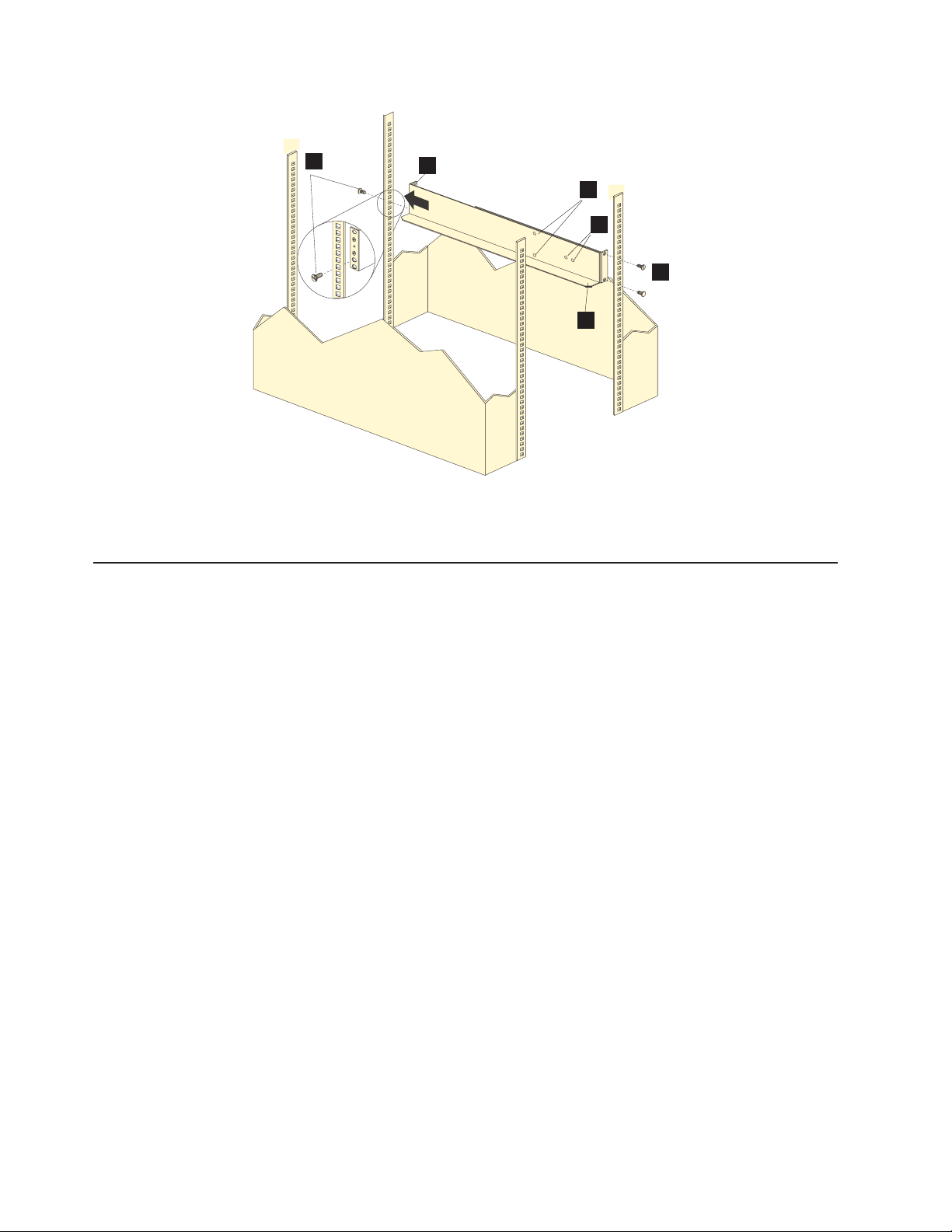
1
Figure 20. Installing the support rails
12. Continue with “Removing the CRUs.”
Installing the DS4700 Express
This section provides instructions on installing the DS4700 Express. The installation
process includes:
v “Removing the CRUs”
v “Installing the DS4700 Express into a rack on the support rails” on page 46
v “Replacing the components” on page 48
3
4
5
2
2
6
Rear of Rack
Removing the CRUs
This section describes how to remove the CRUs to minimize the weight of the
DS4700 Express before you install it in the rack. However, if you have three or
more people available to lift and install the DS4700 Express in a rack, you might
not find it necessary to remove the CRUs before you install the DS4700 Express. If
this is the case, you can skip the CRU removal instructions provided in this section.
Instead, continue with “Installing the DS4700 Express into a rack on the support
rails” on page 46, and then skip the CRU replacement instructions provided in
“Replacing the components” on page 48.
Attention: IBM strongly recommends that you remove CRUs from the DS4700
Express chassis to lessen the weight to make it easier to transfer the DS4700
Express Storage Subsystem from the shipping box to the rack.
Use the following procedures to remove the CRUs from the DS4700 Express before
installation. Use these instructions after you have completed all applicable site,
rack, and preparations (as listed in “Preparing for installation” on page 34) and
installed the support rails (as listed in “Installing the support rails” on page 36).
Alternately, if necessary, you can use these instructions to lighten the DS4700
Express before removing it from the shipping box. The shipping box opens to
provide access to the storage subsystem CRUs.
40 IBM System Storage DS4700 Express Storage Subsystem: Installation, User’s and Maintenance Guide
Page 73

The DS4700 Express comes with a rack-mounting hardware kit for installing it in a
rack. It is easier to lift the DS4700 Express and install it in a rack cabinet if you
remove all the CRUs first. You will need an antistatic wrist strap and a cart or level
surface (to hold the CRUs). Observe the precautions listed in “Handling
static-sensitive devices” on page 33.
In the following procedure, you will remove the following CRUs from the storage
subsystem before you install it in the rack:
v Controllers
v AC power supply and fan units (Models 70A, 70H, 72A, and 72H)
v DC power supply and fan units (Models 70S, 70T, 72S, and 72T)
v Hot-swap E-DDMs
You do not need to remove the blank trays.
Statement 4:
≥ 18 kg (39.7 lb) ≥ 32 kg (70.5 lb) ≥ 55 kg (121.2 lb)
CAUTION:
Use safe practices when lifting.
Attention: The storage subsystem comes with a bezel that is attached to the front
of the unit. The bezel protects the light pipes that are located above the drive trays.
Leave the protective bezel in place until you are instructed to remove it.
Removing a controller
Complete the following steps to remove a controller:
1. Squeeze the controller latch and pull the lever open 90° (so that the lever is
horizontal) to release the controller from the latch. The controller latch is a coral
colored tab on the lever.
Note: The lever rotates upward or downward 90°, depending on whether the
controller you are removing is the right or left controller CRU.
2. Slowly pull the lever away from the chassis to remove the controller from the
bay, as shown in Figure 21 on page 42.
Chapter 2. Installing the storage subsystem 41
Page 74

ds470010
Lever
Figure 21. Removing and replacing a controller
3. Place the controller on a level surface.
4. Repeat step 1 through step 3 for the second controller.
Removing an ac power supply and fan unit
Statement 5:
CAUTION:
The power control button on the device and the power switch on the power
supply do not turn off the electrical current supplied to the device. The device
also might have more than one power cord. To remove all electrical current
from the device, ensure that all power cords are disconnected from the power
source.
2
1
CAUTION:
Disconnect the power cord before removing the power supply and fan unit.
Complete the following steps to remove a power supply and fan unit:
1. Squeeze the latch and pull the lever open 90° (so that the lever is horizontal) to
release the power supply and fan unit from the latch. The latch is a coral
colored tab on the lever.
2. Slowly pull the lever away from the chassis to remove the power supply and fan
unit, as shown in Figure 22 on page 43.
Note: The lever rotates upward or downward 90°, depending on whether the
power supply and fan unit you are removing is in the left or right power
supply and fan unit bay.
42 IBM System Storage DS4700 Express Storage Subsystem: Installation, User’s and Maintenance Guide
Page 75

Ds470011
Lever
Figure 22. Removing a power supply and fan unit
3. Place the power supply and fan unit on a level surface.
4. Repeat step 1 through step 3 for the second power supply and fan unit.
Removing a dc power supply and fan unit
CAUTION:
This unit has more than one power source. To remove all power from the unit,
all dc MAINS must be disconnected.
Statement 29:
Chapter 2. Installing the storage subsystem 43
Page 76
CAUTION:
This equipment is designed to permit the connection of the earthed conductor
of the dc supply circuit to the earthing conductor at the equipment.
This equipment is designed to permit the connection of the earthed conductor
of the dc supply circuit to the earthing conductor at the equipment. If this
connection is made, all of the following conditions must be met:
v This equipment shall be connected directly to the dc supply system
earthing electrode conductor or to a bonding jumper from an earthing
terminal bar or bus to which the dc supply system earthing electrode
conductor is connected.
v This equipment shall be located in the same immediate area (such as,
adjacent cabinets) as any other equipment that has a connection between
the earthed conductor of the same dc supply circuit and the earthing
conductor, and also the point of earthing of the dc system. The dc system
shall not be earthed elsewhere.
v The dc supply source shall be located within the same premises as this
equipment.
v Switching or disconnecting devices shall not be in the earthed circuit
conductor between the dc source and the point of connection of the
earthing electrode conductor.
Statement 30:
CAUTION:
To reduce the risk of electric shock or energy hazards:
v This equipment must be installed by trained service personnel in a
restricted-access location, as defined by the NEC and IEC 60950-1, First
Edition, The Standard for Safety of Information Technology Equipment.
v Connect the equipment to a reliably grounded safety extra low voltage
(SELV) source. An SELV source is a secondary circuit that is designed so
that normal and single fault conditions do not cause the voltages to exceed
a safe level (60 V direct current).
v The branch circuit overcurrent protection must be rated 20 A.
v Use 12 American Wire Gauge (AWG) or 2.5 mm2 copper conductor only, not
exceeding 4.5 meters in length.
v Incorporate a readily available approved and rated disconnect device in the
field wiring.
CAUTION:
Disconnect the power cord before removing the dc power supply and fan unit.
Complete the following steps to remove a dc power supply and fan unit:
1. Squeeze the latch and pull the lever open 90° (so that the lever is horizontal) to
release the dc power supply and fan unit from the latch. The latch is a coral
colored tab on the lever.
2. Slowly pull the lever away from the chassis to remove the dc power supply and
fan unit, as shown in Figure 23 on page 45.
44 IBM System Storage DS4700 Express Storage Subsystem: Installation, User’s and Maintenance Guide
Page 77

Note: The lever rotates upward or downward 90°, depending on whether the dc
power supply and fan unit you are removing is in the left or right dc
power supply and fan unit bay.
ds470071
Figure 23. Removing a dc power supply and fan unit
3. Place the dc power supply and fan unit on a level surface.
4. Repeat step 1 on page 44 through step 3 for the second dc power supply.
Removing an E-DDM
Complete the following steps to remove a hot-swap E-DDM:
Note: The E-DDM comes installed in a drive tray. Do not attempt to detach the
E-DDM from the tray.
1. Use Table 55 on page 194 to record the location and identify your E-DDMs. You
must record this information to be able to replace the E-DDMs in their original
order before they were removed.
2. Release the latch on the E-DDM CRU by pressing on the inside of the bottom
of the tray handle.
3. Lift the closed latch to its open position. (The latch is at a 90° angle to the front
of the E-DDM when open.)
4. Pull the E-DDM out of the bay, as shown in Figure 24 on page 46.
Chapter 2. Installing the storage subsystem 45
Page 78

exp80018
Figure 24. Removing a E-DDM CRU
5. Place the E-DDM CRU horizontally on a level surface.
Attention: Do not stack E-DDM CRUs on top of one another. Protect the
E-DDM CRUs from vibrations or sudden shocks.
6. Repeat step 1 through step 4 on page 45 for additional E-DDM CRUs.
Installing the DS4700 Express into a rack on the support rails
Complete the following steps to install the DS4700 Express in the rack cabinet.
CAUTION:
Do not install modules or other equipment in the top half of a rackmount
cabinet while the bottom half is empty. Doing so can cause the cabinet to
become top-heavy and tip over. Always install hardware in the lowest
available position in the cabinet.
Statement 4:
≥ 18 kg (39.7 lb) ≥ 32 kg (70.5 lb) ≥ 55 kg (121.2 lb)
CAUTION:
Use safe practices when lifting.
1. Put on antistatic protection, and keep it on while performing all of the remaining
procedures in this chapter.
46 IBM System Storage DS4700 Express Storage Subsystem: Installation, User’s and Maintenance Guide
Page 79

2. Using a #2 Phillips screwdriver, remove the four screws from the rails (two
screws in each rail). See 4 in Figure 20 on page 40. If you do not remove
these screws, the storage subsystem will not fit securely.
Note: If the screws are shipped in the hardware pack instead of already
installed in the rails, skip this step and go to step 3.
3. Place the storage subsystem in the rack.
Note: If you have removed the CRUs from the DS4700 Express, you should be
able to lift the unit into the cabinet with the help of one other person. If
you have not removed the CRUs before the installation, you should have
at least two other people available to help you lift the DS4700 Express
into the rack.
a. Move the storage subsystem to the front of the rackmount cabinet.
b. With help from another person, place the back of the storage subsystem on
the support rails, and then slide the unit into the rack as shown in Figure 25.
Front of Rack
Figure 25. Installing the DS4700 Express
4. Secure the storage subsystem. Figure 26 on page 48 shows how to secure the
storage subsystem to the rack.
a. Align the front mounting holes on each side of the storage subsystem with
the mounting holes on the front of the support rails.
b. Using the screws that you removed in step 2, secure the sides in the back
of the DS4700 Express to the rack rails.
c. Secure the front of the DS4700 Express using the four M5 screws as shown
in Figure 26 on page 48.
Chapter 2. Installing the storage subsystem 47
Page 80
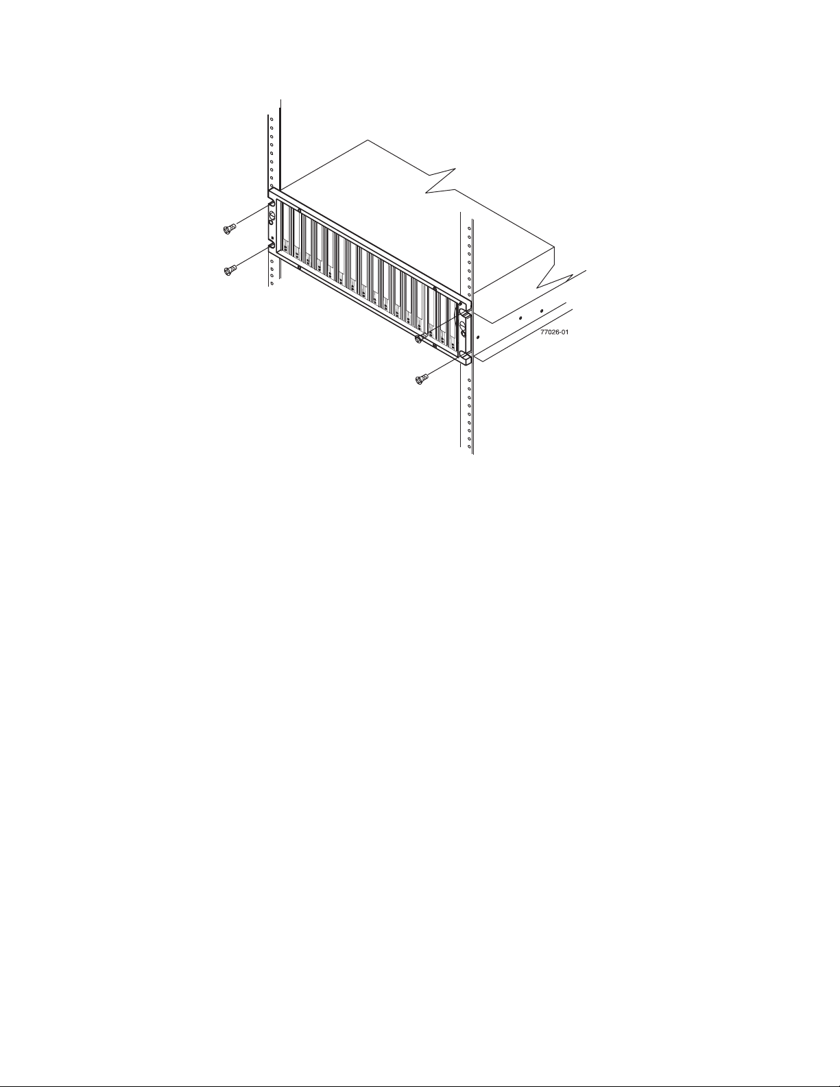
Figure 26. Securing the DS4700 Express to the rack cabinet
5. Continue with one of the following actions:
v If you did remove the DS4700 Express CRUs before installation (as
described in “Removing the CRUs” on page 40), continue with “Replacing the
components.”
v If you did not remove the DS4700 Express CRUs before installation, continue
with Chapter 3, “Cabling the storage subsystem,” on page 55.
Replacing the components
If you removed components from the DS4700 Express Storage Subsystem before
you installed it into a rack cabinet, use the following procedures to replace the
components in the DS4700 Express after it is installed successfully in a rack
cabinet.
Replacing a controller
Complete the following steps to replace the controller that you removed before the
installation:
Attention: After you remove an controller, wait 70 seconds before reseating or
replacing the controller. Failure to do so may cause undesired events. The left and
right controllers are seated in the DS4700 Express chassis in opposite orientations.
If you cannot fully insert the controller into the controller bay, flip it 180° and reinsert
it.
1. Slide one controller into the empty slot in the storage subsystem. Be sure that
the lever is pulled straight out as you slide the controller in, as shown in
Figure 27 on page 49.
48 IBM System Storage DS4700 Express Storage Subsystem: Installation, User’s and Maintenance Guide
Page 81

Notch
Guide pin
Lever
Figure 27. Removing and replacing a controller
2. As you slide the controller into the empty slot, make sure the guide pins on the
side of the controller fit into the notches. After the guide pins fit into the notches
and the controller fits snugly into the bay, push the lever downward or upward
90°, depending on whether the controller is inserted in the A or B controller bay
to fully latch it into place. Do not force fit. The controller is designed to prevent it
from being inserted into the chassis incorrectly.
Attention: Make sure that the levers lock into place in the storage subsystem
chassis.
3. Repeat step 1 on page 48 and step 2 to replace the second controller.
Replacing an ac power supply and fan unit
Statement 5:
CAUTION:
The power control button on the device and the power switch on the power
supply do not turn off the electrical current supplied to the device. The device
also might have more than one power cord. To remove all electrical current
from the device, ensure that all power cords are disconnected from the power
source.
2
1
Chapter 2. Installing the storage subsystem 49
Page 82

CAUTION:
Disconnect the power cord before replacing the power supply and fan unit.
Complete the following steps to replace the power supply and fan units that you
removed before the installation:
1. Slide one power supply and fan unit into the storage subsystem. Be sure to
replace the power supply and fan units so that the lever on each power supply
and fan unit opens toward the interior of the storage subsystem, as shown in
Figure 28. Do not force fit. The power supply and fan unit is designed to prevent
it from being inserted into the chassis incorrectly.
Attention: Be sure that the lever is pulled straight out as you slide the power
supply and fan unit into the storage subsystem, as shown in Figure 28. The left
and right power supply and fan units are seated in the DS4700 Express chassis
in opposite orientations. If you cannot fully insert the power supply and fan unit
into the power supply and fan unit bay, flip it 180° and reinsert it.
Lever
Figure 28. Replacing a power supply and fan unit
2. As you slide the power supply and fan unit into the empty slot, make sure the
guide pins on the side of the power supply and fan unit fit into the notches
along the sides of the power supply and fan unit bay. After the guide pins fit into
the notches and power supply and fan unit fits snugly into the slot, push the
lever upward or downward 90° depending on whether the power supply fan is
inserted in the left or right bay to fully latch it into place. Then gently push the
front of the power supply and fan unit to ensure that it is fully seated.
3. Repeat step 1 and step 2 to replace the second power supply and fan unit.
Replacing a dc power supply and fan unit
Statement 29:
50 IBM System Storage DS4700 Express Storage Subsystem: Installation, User’s and Maintenance Guide
Page 83
CAUTION:
This equipment is designed to permit the connection of the earthed conductor
of the dc supply circuit to the earthing conductor at the equipment.
This equipment is designed to permit the connection of the earthed conductor
of the dc supply circuit to the earthing conductor at the equipment. If this
connection is made, all of the following conditions must be met:
v This equipment shall be connected directly to the dc supply system
earthing electrode conductor or to a bonding jumper from an earthing
terminal bar or bus to which the dc supply system earthing electrode
conductor is connected.
v This equipment shall be located in the same immediate area (such as,
adjacent cabinets) as any other equipment that has a connection between
the earthed conductor of the same dc supply circuit and the earthing
conductor, and also the point of earthing of the dc system. The dc system
shall not be earthed elsewhere.
v The dc supply source shall be located within the same premises as this
equipment.
v Switching or disconnecting devices shall not be in the earthed circuit
conductor between the dc source and the point of connection of the
earthing electrode conductor.
Statement 30:
CAUTION:
To reduce the risk of electric shock or energy hazards:
v This equipment must be installed by trained service personnel in a
restricted-access location, as defined by the NEC and IEC 60950-1, First
Edition, The Standard for Safety of Information Technology Equipment.
v Connect the equipment to a reliably grounded safety extra low voltage
(SELV) source. An SELV source is a secondary circuit that is designed so
that normal and single fault conditions do not cause the voltages to exceed
a safe level (60 V direct current).
v The branch circuit overcurrent protection must be rated 20 A.
v Use 12 American Wire Gauge (AWG) or 2.5 mm2 copper conductor only, not
exceeding 4.5 meters in length.
v Incorporate a readily available approved and rated disconnect device in the
field wiring.
CAUTION:
Disconnect the power cord before replacing the power supply and fan unit.
CAUTION:
This unit has more than one power source. To remove all power from the unit,
all dc MAINS must be disconnected.
Chapter 2. Installing the storage subsystem 51
Page 84
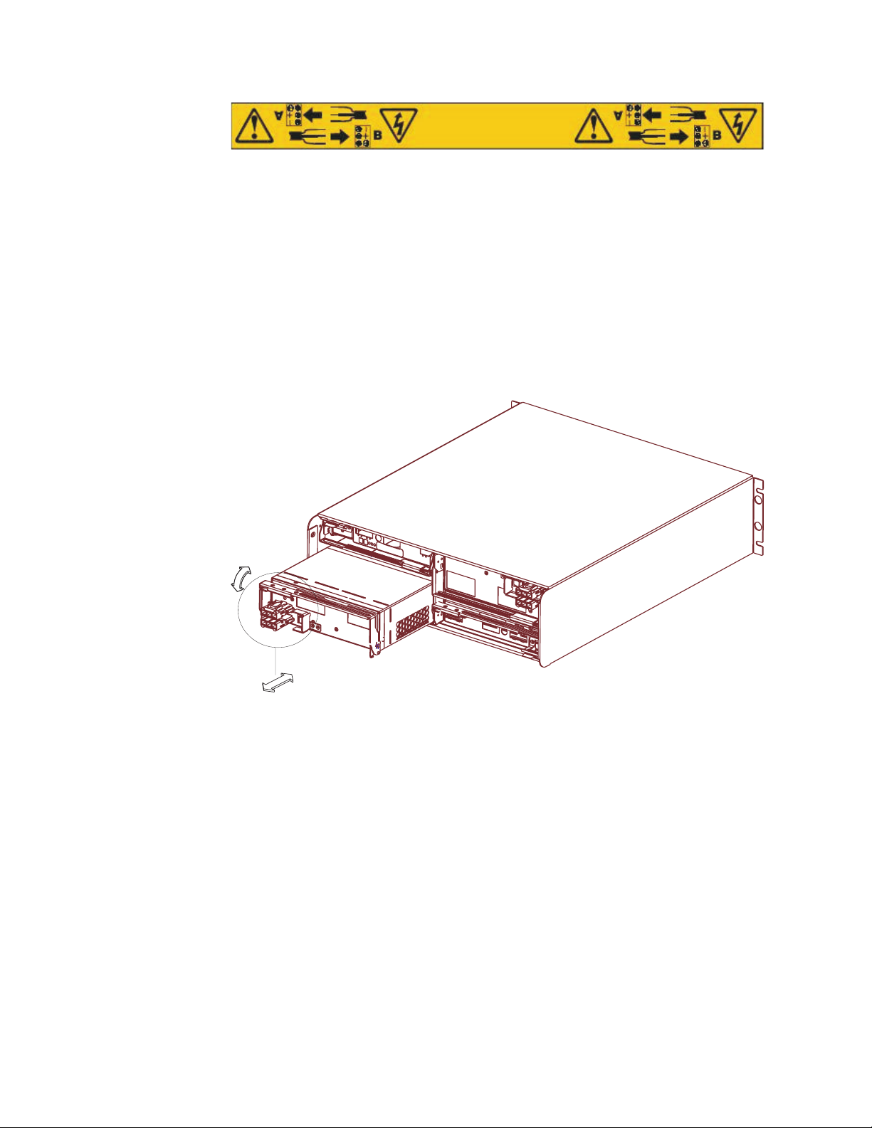
Complete the following steps to replace the dc power supply and fan units that you
removed before the installation:
1. Slide one dc power supply and fan unit into the storage subsystem. Be sure to
replace the dc power supply and fan unit so that the lever on each dc power
supply and fan unit opens toward the interior of the storage subsystem, as
shown in Figure 29. Do not force fit. The dc power supply and fan unit is
designed to prevent it from being inserted into the chassis incorrectly.
Attention: Be sure that the lever is pulled straight out as you slide the dc
power supply and fan unit into the storage subsystem, as shown in Figure 29.
The left and right dc power supplies are seated in the DS4700 Express chassis
in opposite orientations. If you cannot fully insert the dc power supply and fan
unit into the dc power supply and fan unit bay, flip it 180° and reinsert it.
ds470071
Figure 29. Replacing a dc power supply and fan unit
2. As you slide the dc power supply and fan unit into the empty slot, make sure
the guide pins on the side of the dc power supply fit into the notches along the
sides of the dc power supply bay. After the guide pins fit into the notches and dc
power supply fits snugly into the slot, push the lever upward or downward 90°
depending on whether the dc power supply is inserted in the left or right bay to
fully latch it into place. Then gently push the front of the dc power supply to
ensure that it is fully seated.
3. Repeat step 1 and step 2 to replace the second dc power supply and fan unit.
Replacing an E-DDM
Complete the following steps to replace the hot-swap E-DDMs that you removed
before the installation.
Attention: After you remove a E-DDM CRU, wait 70 seconds before replacing or
reseating the E-DDM CRU to allow the E-DDM to properly spin down. Failure to do
so may cause undesired events.
52 IBM System Storage DS4700 Express Storage Subsystem: Installation, User’s and Maintenance Guide
Page 85
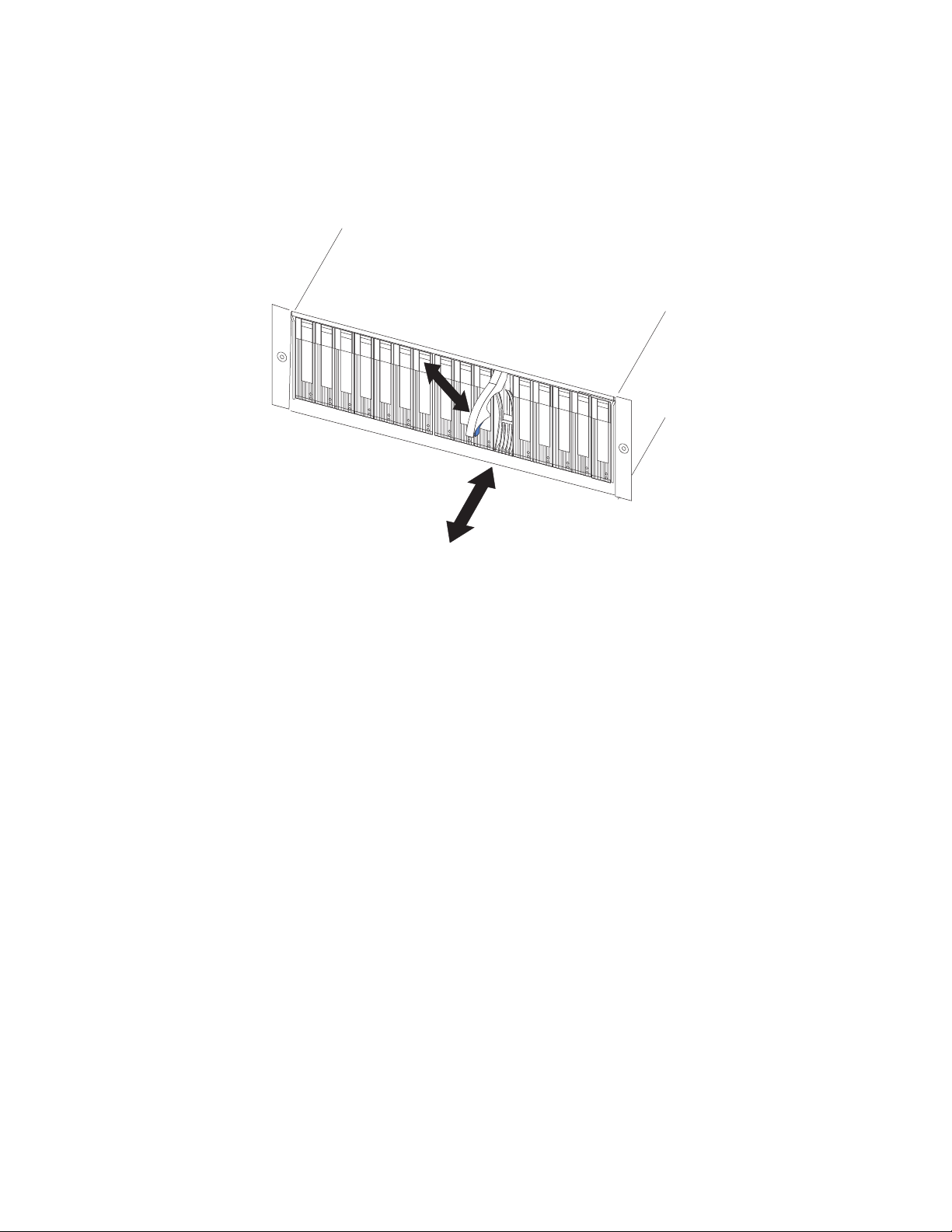
Note: Use Table 55 on page 194 to verify the proper replacement locations of your
E-DDMs.
1. Lift up on the handle and gently push the E-DDM CRU into the empty bay until
the hinge of the tray handle latches beneath the storage subsystem bezel, as
shown in Figure 30.
exp80018
Figure 30. Replacing an E-DDM
2. Push the tray handle down until the latch clicks into place.
3. Repeat step 1 and step 2 to replace additional E-DDMs.
Installing a Telco bezel
Complete the following step to install a bezel on a DS4700 Express Storage
Subsystem if the storage subsystem is shipped with one:
v Grasp the sides of the bezel and snap it onto the DS4700 Express chassis, as
shown in Figure 31 on page 54. The bezel is self-aligned in the recessed
opening in the front of the DS4700 Express chassis.
Chapter 2. Installing the storage subsystem 53
Page 86
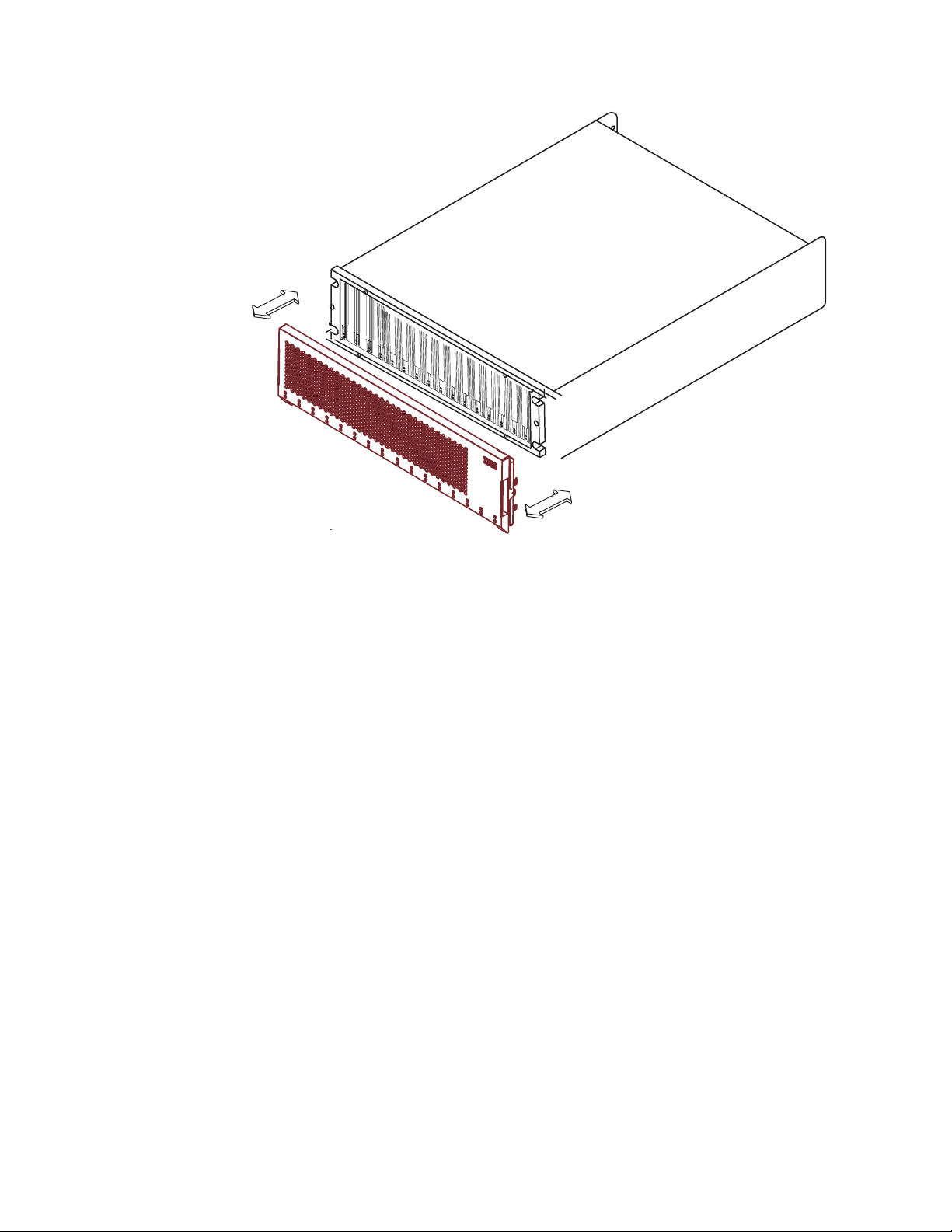
Figure 31. Installing a Telco bezel
ds470067
54 IBM System Storage DS4700 Express Storage Subsystem: Installation, User’s and Maintenance Guide
Page 87

Chapter 3. Cabling the storage subsystem
After the storage subsystem is installed in its permanent location, you must cable it
to hosts, drives, and other external devices, depending on your hardware
configuration.
This chapter addresses the following cabling and configuration topics:
v “Enclosure ID settings ”
v “Fibre-channel loop and ID settings” on page 56
v “Working with SFPs and fiber-optic cables” on page 56
v “Connecting storage expansion enclosures to the DS4700 Express” on page 68
v “Intermixing storage expansion enclosures in the same drive loop” on page 99
v “Connecting hosts to the DS4700 Express” on page 104
v “Connecting secondary interface cables” on page 100
v “Configuring the storage subsystem” on page 101
v “Installing the storage subsystem configuration” on page 110
v “Cabling the ac power supply for ac models” on page 111
v “Cabling the dc power supply for dc models” on page 111
Enclosure ID settings
The enclosure ID, comprised of two seven-segment numbers, is located on the
back of each controller next to the indicator lights. It provides a unique identifier for
each enclosure in the DS4000 storage subsystem configuration.
The controller automatically sets the enclosure ID number. You can change the
setting through the storage management software if necessary. Both controller
enclosure ID numbers are identical under normal operating conditions. Each
storage expansion enclosure (including the DS4700 Express Storage Subsystem) in
the DS4000 storage subsystem configuration must have a unique storage enclosure
ID. In addition, the single digits (x1) of the enclosure IDs of all storage expansion
enclosures (including the DS4700 Express Storage Subsystem) in the redundant
drive channel/loop pair must be unique.
The allowable ranges for enclosure ID settings are 0-99. However, IBM
recommends that you do not set the enclosure ID to 00 or any number less than
80. The DS4700 Express enclosure ID is normally set to a value of 85 at the
factory.
Figure 32 on page 56 shows the enclosure ID on models 70 and 72.
© Copyright IBM Corp. 2010 55
Page 88

1
1
Figure 32. Storage subsystem seven-segment enclosure ID on models 70 and 72
Table 22. Description of Figure 32
Number Description
1 Enclosure ID
Fibre-channel loop and ID settings
When you install a hard disk drive in the storage subsystem, the drive tray plugs
into a printed circuit board called the midplane. The midplane sets the fibre-channel
loop ID automatically, based on the enclosure ID switch setting and the physical
location (bay) of the hard disk drive.
1
ds470005
1
Working with SFPs and fiber-optic cables
Each RAID controller has up to four single-ported host channel connections
(depending on the model) and two dual-ported drive channel connections. You use
a small-form factor pluggable transceiver (SFP) to connect each host channel port
and drive channel port to hosts and storage expansion enclosures. The SFP is
inserted into the port, and then a fiber-optic cable is inserted into the SFP. The
other end of the fiber-optic cable connects to an external device. SFPs are laser
products.
Statement 3:
56 IBM System Storage DS4700 Express Storage Subsystem: Installation, User’s and Maintenance Guide
Page 89

CAUTION:
When laser products (such as CD-ROMs, DVD drives, fiber optic devices, or
transmitters) are installed, note the following:
v Do not remove the covers. Removing the covers of the laser product could
result in exposure to hazardous laser radiation. There are no serviceable
parts inside the device.
v Use of controls or adjustments or performance of procedures other than
those specified herein might result in hazardous radiation exposure.
DANGER
Some laser products contain an embedded Class 3A or Class 3B laser
diode. Note the following.
Laser radiation when open. Do not stare into the beam, do not view directly
with optical instruments, and avoid direct exposure to the beam.
Handling fibre-optic cables
Attention: To avoid damage to your fibre-optic cables, follow these guidelines:
v For devices on slide rails, leave enough slack in the cables so they do not bend
to a diameter of less than 76 mm (3 in.), or a radius less than 38 mm (1.5 in.),
when extended or become pinched when retracted.
v Do not overtighten the cable straps or bend the cables to a diameter of less than
76 mm (3 in.), or a radius less than 38 mm (1.5 in.).
v When storing excess or unused fibre-optic cables, do not bend the cables to a
diameter of less than 76 mm (3 in.), or a radius less than 38 mm (1.5 in.) or wrap
them around themselves. See Figure 33 on page 58.
v Loop diameter of 76 mm (3 in.) and bend radius of 38 mm (1.5 in.) for fibre-optic
cables are IBM DS4000 recommended minimums. Loops or bends smaller than
this recommendation may cause damage to your fiber optic cables. It is best
practice to use loop diameters and bend radii that are greater than these
recommended minimums.
v Do not route the cable along a folding cable-management arm.
v Route the cable away from places where it can be damaged by other devices in
the rack cabinet.
v Do not put excess weight on the cable at the connection point. Be sure that the
cable is well supported.
v Do not use plastic cable ties in place of the provided cable straps.
v The following are the supported maximum cable lengths:
– 1 Gbps: 500 meters 50/125 um fiber, 300 meters 62.5/125 um fiber
– 2 Gbps: 300 meters 50/125 um fiber, 150 meters 62.5/125 um fiber
– 4 Gbps: 150 meters 50/125 um fiber, 70 meters 62.5/125 um fiber
Chapter 3. Cabling the storage subsystem 57
Page 90

Figure 33. Recommended bending and looping specifications for fibre-optic cables
Installing SFP modules
The DS4700 Express requires SFP modules. SFP modules convert electrical
signals to optical signals that are required for fibre channel transmission to and from
RAID controllers. After you install the SFP modules, you use fibre-optic cables to
connect the DS4700 Express to other fibre channel devices.
Before installing SFP modules and fibre-optic cables, read the following information:
v Do not mix long-wave SFPs and short-wave SFPs on a single storage
subsystem. Use only short-wave SFPs. You can use the DS4000 Storage
Manager client to view the Storage Subsystem Profile to verify that you are not
mixing long-wave and short-wave SFPs.
Attention: In addition, do not use long-wave SFPs or GBICs in any of the fibre
channel ports in the DS4700 Express controllers. (Long-wave SFPs and GBICs
are not supported for use in the DS4700 Express or any of the attached DS4000
storage expansion enclosures.)
v The SFP module housing has an integral guide key that is designed to prevent
you from inserting the SFP module improperly.
v Use minimal pressure when inserting an SFP module into an SFP port. Forcing
the SFP module into a port could cause damage to the SFP module or to the
port.
v You can insert or remove the SFP module while the port is powered on.
v Do not install an SFP in any port that will not have a fibre optic cable attached.
Additionally, it is recommended that you remove any SFP from any port that does
not have fibre optic cables attached.
v The operational or redundant loop performance is not affected when you install
or remove an SFP module.
v You must insert the SFP module into a port before you connect the fiber-optic
cable.
ds470104
1.5 inch
(38 mm)
radius
3.0 inch
(76 mm)
diameter
58 IBM System Storage DS4700 Express Storage Subsystem: Installation, User’s and Maintenance Guide
Page 91

v You must remove the fiber-optic cable from the SFP module before you remove
the SFP module from the port. Refer to “Removing SFP modules” on page 60 for
more information.
v The maximum operating speed of the fibre channel port is determined by two
factors: the speed of the SFP module that is installed and the speed of the fibre
channel connection. For example, a 2-Gbps SFP that is plugged into a
4-Gbps-capable port will limit the speed of that port to a maximum of 2 Gbps.
Conversely, a 4-Gbps SFP that is plugged into a 2-Gbps-capable port will limit
the speed of the port to a maximum of 2 Gbps.
Attention: Carefully check the SFP's IBM part number, option number, and
FRU part number to identify its speed. There are no physical features that
distinguish a 4 Gbps from a 2 Gbps SFP.
Statement 3:
CAUTION:
When laser products (such as CD-ROMs, DVD drives, fiber optic devices, or
transmitters) are installed, note the following:
v Do not remove the covers. Removing the covers of the laser product could
result in exposure to hazardous laser radiation. There are no serviceable
parts inside the device.
v Use of controls or adjustments or performance of procedures other than
those specified herein might result in hazardous radiation exposure.
DANGER
Some laser products contain an embedded Class 3A or Class 3B laser
diode. Note the following.
Laser radiation when open. Do not stare into the beam, do not view directly
with optical instruments, and avoid direct exposure to the beam.
Attention: When you handle static-sensitive devices, take precautions to avoid
damage from static electricity. For details about handling static-sensitive devices,
see “Handling static-sensitive devices” on page 33.
To install an SFP module, complete the following steps:
1. Remove the SFP module from its static-protective package.
2. Remove the protective cap from the SFP module, as shown in Figure 34 on
page 60. Save the protective cap for future use.
Chapter 3. Cabling the storage subsystem 59
Page 92
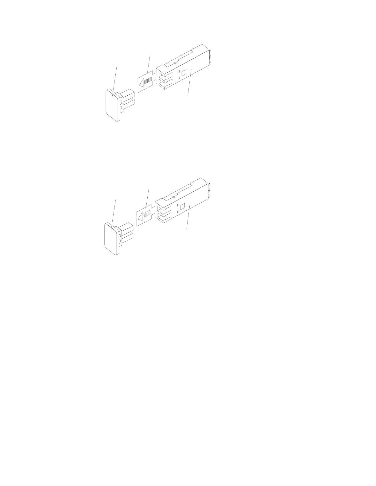
Plastic tab
Protective cap
SFP module
Figure 34. SFP module and protective cap
3. Remove the protective cap from the SFP port. Save the protective cap for future
use.
4. Insert the SFP module into the host port until it clicks into place. See Figure 35.
Plastic tab
Protective cap
Figure 35. Installing an SFP module into the host port
5. Connect an LC-LC fibre-channel cable. For information about the LC-LC cable,
see “Using LC-LC fibre-channel cables” on page 61.
Removing SFP modules
Complete the following steps to remove the SFP module from the host port:
Attention: To avoid damage to the cable or to the SFP module, make sure that
you unplug the LC-LC fibre-channel cable before you remove the SFP module.
1. Remove the LC-LC fibre-channel cable from the SFP module. For more
information, see “Removing an LC-LC fibre-channel cable” on page 64.
2. Unlock the SFP module latch:
v For SFP modules that contain plastic tabs, unlock the SFP module latch by
pulling the plastic tab outward 10°, as shown in Figure 36 on page 61.
SFP module
60 IBM System Storage DS4700 Express Storage Subsystem: Installation, User’s and Maintenance Guide
Page 93

Plastic tab
Protective cap
o
10
SFP module
Figure 36. Unlocking the SFP module latch - plastic variety
v For SFP modules that contain wire tabs, unlock the SFP module latch by
pulling the wire latch outward 90°, as shown in Figure 37.
Wire
tab
Protective
cap
o
90
SFP
module
Figure 37. Unlocking the SFP module latch - wire variety
3. With the SFP latch in the unlocked position, extract the SFP module.
v For SFP modules that contain plastic tabs, slide the SFP module out of the
port.
v For SFP modules that contain wire tabs, grasp the wire latch and pull the
SFP module out of the mini-hub port.
4. Replace the protective cap on the SFP module.
5. Place the SFP module into a static-protective package.
6. Replace the protective cap on the host port.
Using LC-LC fibre-channel cables
The LC-LC fibre-channel cable is a fiber-optic cable that you use to connect
DS4700 Express fibre channel ports into one of the following devices:
v An SFP module installed in a fibre channel switch port
v An SFP module of the host bus adapter port
v An SFP module installed in an IBM DS4000 storage expansion enclosure
See Figure 38 on page 62 for an illustration of the LC-LC fibre-channel cable.
For more information about cabling these devices, see the documentation that
comes with the LC-LC fibre-channel cable.
Chapter 3. Cabling the storage subsystem 61
Page 94

Figure 38. LC-LC fibre-channel cable
Connecting an LC-LC cable to an SFP module
Complete the following steps to connect an LC-LC fibre-channel cable to an SFP
module:
Statement 3:
CAUTION:
When laser products (such as CD-ROMs, DVD drives, fiber optic devices, or
transmitters) are installed, note the following:
v Do not remove the covers. Removing the covers of the laser product could
result in exposure to hazardous laser radiation. There are no serviceable
parts inside the device.
v Use of controls or adjustments or performance of procedures other than
those specified herein might result in hazardous radiation exposure.
DANGER
Some laser products contain an embedded Class 3A or Class 3B laser
diode. Note the following.
Laser radiation when open. Do not stare into the beam, do not view directly
with optical instruments, and avoid direct exposure to the beam.
1. Read the information in “Handling fibre-optic cables” on page 57.
2. If necessary, remove the protective cap from the SFP module, as shown in
Figure 34 on page 60. Save the protective cap for future use.
3. Remove the two protective caps from one end of the LC-LC cable, as shown in
Figure 39 on page 63. Save the protective caps for future use.
62 IBM System Storage DS4700 Express Storage Subsystem: Installation, User’s and Maintenance Guide
Page 95

Fibre-optic
cable
Protective cap
Figure 39. Removing fiber-optic cable protective caps
4. Carefully insert this end of the LC-LC cable into an SFP module that is installed
in the DS4700 Express. The cable connector is keyed to ensure it is inserted
into the SFP module correctly. Holding the connector, push in the cable until it
clicks into place, as shown in Figure 40.
Figure 40. Inserting an LC-LC fibre-channel cable into an SFP module
5. Remove the two protective caps from the other end of the LC-LC cable. Save
the protective caps for future use.
6. Connect this end of the LC-LC cable to one of the following devices:
v An SFP module that is installed in a separate EXP810 or EXP710 storage
expansion enclosure or other DS4000 storage expansion enclosure
v An SFP module that is installed in a fibre channel switch port
v A fibre channel host bus adapter port
Chapter 3. Cabling the storage subsystem 63
Page 96

Removing an LC-LC fibre-channel cable
Complete the following steps to remove an LC-LC fibre-channel cable:
Attention: To avoid damaging the LC-LC cable or SFP module, make sure that
you observe the following precautions:
v Press and hold the lever to release the latches before you remove the cable from
the SFP module.
v Ensure that the levers are in the released position when you remove the cable.
v Do not grasp the SFP module plastic tab when you remove the cable.
1. On the end of the LC-LC cable that connects into the SFP module or host bus
adapter, press down and hold the lever to release the latches, as shown in
Figure 41.
Lever
Latches
Figure 41. LC-LC fibre-channel cable lever and latches
2. While pressing down the cable lever, carefully pull on the connector to remove
the cable from the SFP module, as shown in Figure 42.
Figure 42. Removing the LC-LC fibre-channel cable
3. Replace the protective caps on the cable ends.
4. Replace the protective cap on the SFP module.
Using LC-SC fibre-channel cable adapters
The LC-SC fibre-channel cable adapter is a fiber-optic cable that is used to connect
an LC connector into one of the following devices that require SC connectors:
v 1-Gbps fibre channel switch
v Fibre channel host bus adapter
Attention: The DS4700 Express does not support the attachment of storage
expansion enclosures that operate at 1 Gbps, such as the EXP500.
64 IBM System Storage DS4700 Express Storage Subsystem: Installation, User’s and Maintenance Guide
Page 97
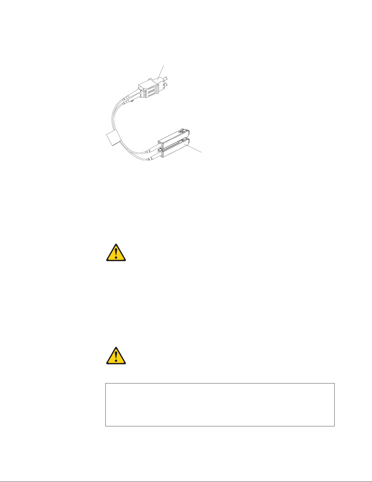
For more information about connecting to these devices, see the documentation
that comes with the LC-SC fibre-channel cable adapter.
LC connector
f10ug012
SC connector
Figure 43. LC-SC fibre-channel cable adapter
The following sections provide the procedures for properly connecting and removing
an LC-SC fibre-channel cable.
Connecting an LC-SC cable adapter to a device
Complete the following steps to connect an LC-SC fibre-channel cable adapter to a
device:
Statement 3:
CAUTION:
When laser products (such as CD-ROMs, DVD drives, fiber optic devices, or
transmitters) are installed, note the following:
v Do not remove the covers. Removing the covers of the laser product could
result in exposure to hazardous laser radiation. There are no serviceable
parts inside the device.
v Use of controls or adjustments or performance of procedures other than
those specified herein might result in hazardous radiation exposure.
DANGER
Some laser products contain an embedded Class 3A or Class 3B laser
diode. Note the following.
Laser radiation when open. Do not stare into the beam, do not view directly
with optical instruments, and avoid direct exposure to the beam.
1. Read the information in “Handling fibre-optic cables” on page 57.
Chapter 3. Cabling the storage subsystem 65
Page 98
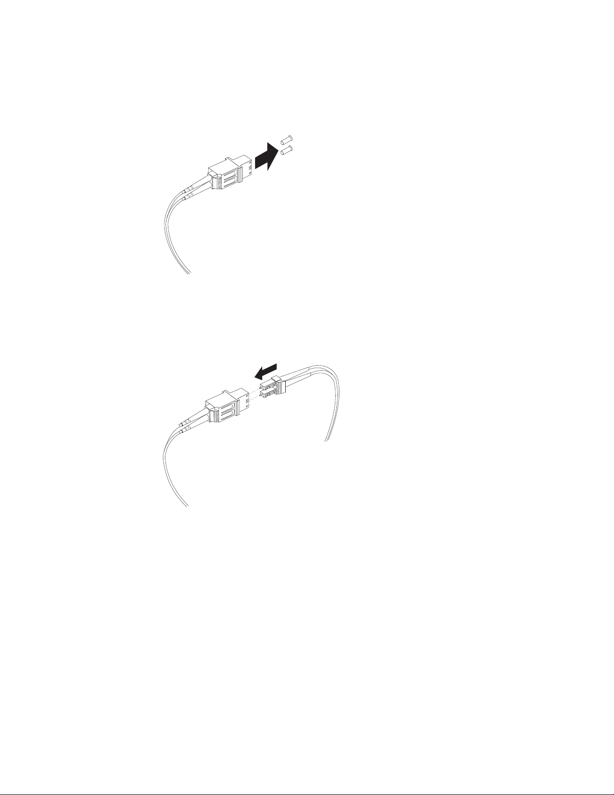
2. Connect one end of an LC-LC cable to an SFP module in the DS4700 Express.
For instructions, see “Using LC-LC fibre-channel cables” on page 61.
3. Remove the two protective caps from the LC connector end of the LC-SC cable
adapter as shown in Figure 44. Save the protective caps for future use.
f10ug013
Figure 44. Removing the LC-SC cable adapter protective caps
4. Carefully insert the other end of the LC-LC cable into the LC connector end of
the LC-SC cable adapter as shown in Figure 45. Push in the connector until it
clicks into place.
f10ug020
Figure 45. Connecting an LC-LC cable into the LC-SC cable adapter
5. If you are connecting the DS4700 Express to a 1-Gbps fibre channel switch or
fibre channel host bus adapter, connect the SC connector end of the LC-SC
cable adapter to a Gigabit Interface Converter (GBIC) that is installed in the
1-Gbps fibre channel switch or fibre channel host bus adapter. For more
information about connecting to these devices, see the documentation that
comes with the device.
Removing an LC-LC cable from an LC-SC cable adapter
Complete the following steps to remove an LC-LC cable from an LC-SC cable
adapter:
66 IBM System Storage DS4700 Express Storage Subsystem: Installation, User’s and Maintenance Guide
Page 99
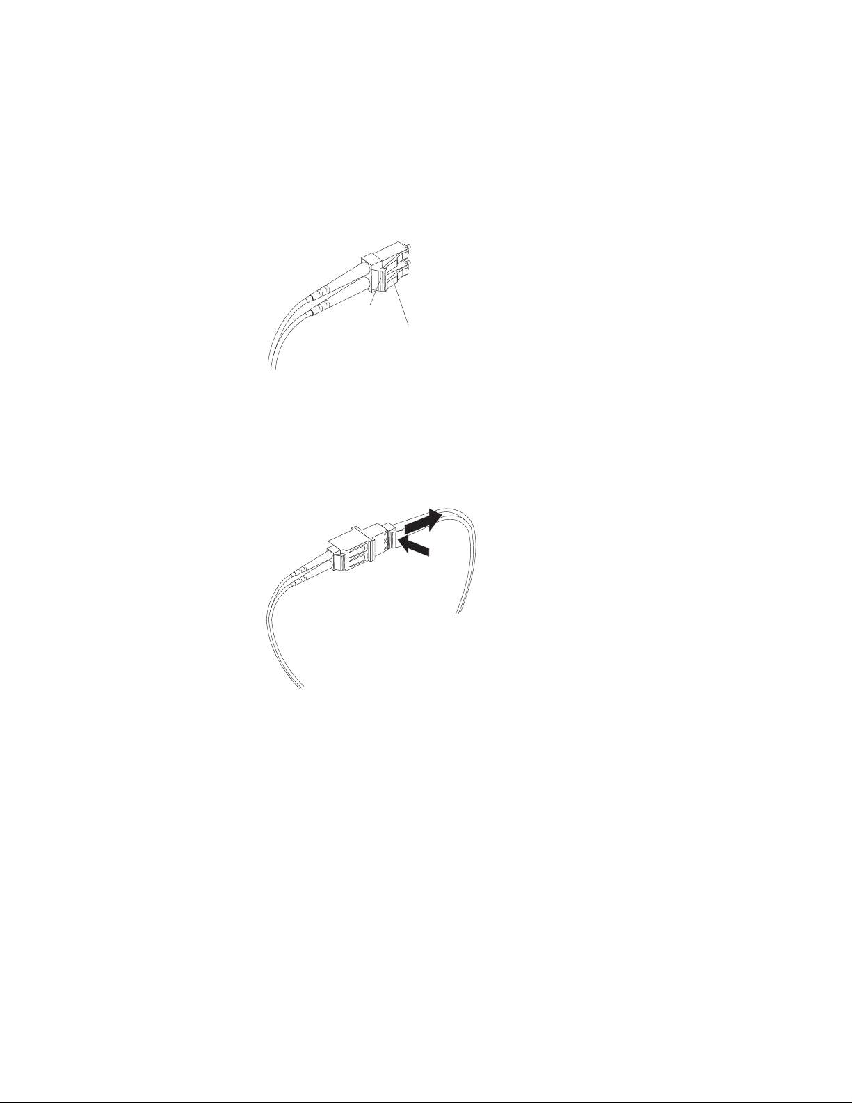
Attention: To avoid damaging the LC-LC cable, make sure you press and hold
the lever to release the latches before you remove the cable from an LC-SC cable
adapter. Ensure that both levers are in the released position when removing the
cable. When removing the cable from the SFP module, make sure you do not grasp
the SFP module plastic tab.
1. On the end of the cable that connects into the LC connector end of the LC-SC
cable adapter, press down and hold the lever to release the latches. Figure 46
shows the location of the lever and latches.
Lever
Latches
Figure 46. LC-LC fibre-channel cable lever and latches
f10ug018
2. Carefully pull on the connector to remove it. Make sure you grasp the connector
and not the cable when removing the LC-LC cable from the LC-SC cable
adapter as shown in Figure 47.
f10ug015
Figure 47. Removing the LC-LC fibre-channel cable from an LC-SC fibre-channel cable
adapter
3. Replace the protective caps on the cable ends.
Chapter 3. Cabling the storage subsystem 67
Page 100

Connecting storage expansion enclosures to the DS4700 Express
Attention
Before powering on the DS4700 Express Storage Subsystem, it must be
populated with at least two E-DDMs. If at least two E-DDMs are not installed
in each attached storage expansion enclosure or DS4700 Express Storage
Subsystem, when you power on the DS4700 Express and its attached storage
expansion enclosures, your standard storage partition key might be lost and
must be regenerated using instructions on the IBM DS4000 Solutions and
Premium Features Web site:
https://www-912.ibm.com/PremiumFeatures/
In addition, the resulting insufficient load to the enclosure power supplies
might cause them to intermittently appear as failed, falsely indicating the
power supplies are bad. All drives in the DS4700 Express Storage Subsystem
and the connected storage expansion enclosure or enclosures must contain
no prior configuration data.
In the initial installation of the DS4700 Express, you can add only new storage
expansion enclosures to the DS4700 Express Storage Subsystem. This means
there must be no existing configuration information on the storage expansion
enclosures that you want to install.
If the storage expansion enclosures that you want to install currently contain logical
drives or configured hot spares, and you want them to be part of the DS4700
Express Storage Subsystem configuration, refer to the IBM System Storage
DS4000 Hard Drive and Storage Expansion Enclosure Installation and Migration
Guide. Improper drive migration might cause loss of configuration and other storage
subsystem problems. Contact your IBM technical support representative for
additional information.
Redundant drive channel pair
Each controller on the DS4700 Express has a drive channel that contains two ports.
The storage expansion enclosures that are connected to these two ports form a
drive channel (also referred to as drive loop in certain DS4000 storage subsystem
models). The maximum number of hard drives that can be installed in one drive
channel is 112. One drive channel from each controller combines to form a
redundant drive channel pair.
Figure 48 on page 69 shows an example of a redundant drive channel pair. If any
component of the drive channel fails, the RAID controllers can still access the
storage expansion enclosures in the redundant drive channel pair.
Note: In the following drive cabling figures, the DS4700 Express graphics are
simplified to show only the drive ports of each controller.
68 IBM System Storage DS4700 Express Storage Subsystem: Installation, User’s and Maintenance Guide
 Loading...