

Page 1

IBM TotalStorage DS4100 Storage Server
Installation, User’ s, and Maintenance Guid e
GC26-7712-00
Page 2

Page 3

IBM TotalStorage DS4100 Storage Server
Installation, User’ s, and Maintenance Guid e
GC26-7712-00
Page 4

Note:
Before using this information and the product it supports, be sure to read the general information in “Notices” on page 127.
First Edition (November 2004)
© Copyright International Business Machines Corporation 2004. All rights reserved.
US Government Users Restricted Rights – Use, duplication or disclosure restricted by GSA ADP Schedule Contract
with IBM Corp.
Page 5

Safety
The caution and danger statements that this document contains can be referenced
in the multilingual IBM
TotalStorage
®
DS4100 storage server. Each caution and danger statement is
®
Safety Information document that is provided with your IBM
numbered for easy reference to the corresponding statements in the translated
document.
v Danger: These statements indicate situations that can be potentially lethal or
extremely hazardous to you. A danger statement is placed just before the
description of a potentially lethal or extremely hazardous procedure, step, or
situation.
v Caution: These statements indicate situations that can be potentially hazardous
to you. A caution statement is placed just before the description of a potentially
hazardous procedure step or situation.
v Attention: These notices indicate possible damage to programs, devices, or
data. An attention notice is placed just before the instruction or situation in which
damage could occur.
installing this product, read the following danger and caution notices.
Before
© Copyright IBM Corp. 2004 iii
Page 6
Statement 1:
DANGER
Electrical
current from power, telephone, and communication cables is
hazardous.
To avoid a shock hazard:
v Do not connect or disconnect any cables or perform installation,
maintenance, or reconfiguration of this product during an electrical
storm.
v Connect all power cords to a properly wired and grounded electrical
outlet.
v Connect to properly wired outlets any equipment that will be attached to
this product.
v When possible, use one hand only to connect or disconnect signal
cables.
v Never turn on any equipment when there is evidence of fire, water, or
structural damage.
v Disconnect the attached power cords, telecommunications systems,
networks, and modems before you open the device covers, unless
instructed otherwise in the installation and configuration procedures.
v Connect and disconnect cables as described in the following table when
installing, moving, or opening covers on this product or attached
devices.
To Connect: To Disconnect:
1. Turn everything OFF.
2. First, attach all cables to devices.
3. Attach signal cables to connectors.
4. Attach power cords to outlet.
1. Turn everything OFF.
2. First, remove power cords from outlet.
3. Remove signal cables from connectors.
4. Remove all cables from devices.
5. Turn device ON.
iv IBM TotalStorage DS4100 Storage Server: Installation, User’s, and Maintenance Guide
Page 7
Statement 3:
CAUTION:
When laser products (such as CD-ROMs, DVD drives, fiber optic devices, or
transmitters) are installed, note the following:
v Do not remove the covers. Removing the covers of the laser product could
result in exposure to hazardous laser radiation. There are no serviceable
parts inside the device.
v Use of controls or adjustments or performance of procedures other than
those specified herein might result in hazardous radiation exposure.
DANGER
laser products contain an embedded Class 3A or Class 3B laser
Some
diode. Note the following.
Laser radiation when open. Do not stare into the beam, do not view directly
with optical instruments, and avoid direct exposure to the beam.
Class 1 Laser statement
IEC 825-11993 CENELEC EN 60 825
Safety v
Page 8
Statement 4:
≥ 18 kg (39.7 lb) ≥ 32 kg (70.5 lb) ≥ 55 kg (121.2 lb)
CAUTION:
Use safe practices when lifting.
Statement 5:
CAUTION:
The power control button on the device and the power switch on the power
supply do not turn off the electrical current supplied to the device. The device
also might have more than one power cord. To remove all electrical current
from the device, ensure that all power cords are disconnected from the power
source.
2
1
vi IBM TotalStorage DS4100 Storage Server: Installation, User’s, and Maintenance Guide
Page 9
Statement 8:
CAUTION:
Never remove the cover on a power supply or any part that has the following
label attached.
Hazardous voltage, current, and energy levels are present inside any
component that has this label attached. There are no serviceable parts inside
these components. If you suspect a problem with one of these parts, contact
a service technician.
Safety vii
Page 10

viii IBM TotalStorage DS4100 Storage Server: Installation, User’s, and Maintenance Guide
Page 11

Contents
Safety . . . . . . . . . . . . . . . . . . . . . . . . . . . . iii
Figures . . . . . . . . . . . . . . . . . . . . . . . . . . . xiii
Tables . . . . . . . . . . . . . . . . . . . . . . . . . . . .xv
About this document . . . . . . . . . . . . . . . . . . . . . xvii
FAStT product renaming . . . . . . . . . . . . . . . . . . . . . xvii
Who should read this document . . . . . . . . . . . . . . . . . . xvii
How this document is organized . . . . . . . . . . . . . . . . . . xviii
Notices and statements used in this document . . . . . . . . . . . . . xviii
Figures used in this document . . . . . . . . . . . . . . . . . . . xix
DS4000 installation process overview . . . . . . . . . . . . . . . . xix
DS4000 Storage Server publications . . . . . . . . . . . . . . . . .xx
DS4500 storage server library . . . . . . . . . . . . . . . . . .xx
DS4400 storage server library . . . . . . . . . . . . . . . . . . xxii
DS4300 storage server library . . . . . . . . . . . . . . . . . . xxiii
DS4100 storage server library . . . . . . . . . . . . . . . . . . xxiii
DS4000-related hardware publications . . . . . . . . . . . . . . . xxv
DS4000 Storage Manager Version 9 publications . . . . . . . . . . . xxvi
Getting information, help, and service . . . . . . . . . . . . . . . . xxvii
Before you call . . . . . . . . . . . . . . . . . . . . . . . xxvii
Using the documentation . . . . . . . . . . . . . . . . . . . xxvii
Web sites . . . . . . . . . . . . . . . . . . . . . . . . . xxvii
Software service and support . . . . . . . . . . . . . . . . . . xxviii
Hardware service and support . . . . . . . . . . . . . . . . . xxviii
Fire suppression systems . . . . . . . . . . . . . . . . . . . xxviii
How to send your comments . . . . . . . . . . . . . . . . . . . xxix
Chapter 1. Introduction . . . . . . . . . . . . . . . . . . . . . .1
Overview . . . . . . . . . . . . . . . . . . . . . . . . . . .1
About the DS4100 base storage server . . . . . . . . . . . . . . .1
About the DS4100 single-controller storage server . . . . . . . . . . .2
Fibre channel defined . . . . . . . . . . . . . . . . . . . . . .3
SATA defined . . . . . . . . . . . . . . . . . . . . . . . . .3
Product updates . . . . . . . . . . . . . . . . . . . . . . . .3
Features at a glance . . . . . . . . . . . . . . . . . . . . . .4
Clustering support . . . . . . . . . . . . . . . . . . . . . . .5
Inventory checklist . . . . . . . . . . . . . . . . . . . . . . . .5
Best practices guidelines . . . . . . . . . . . . . . . . . . . . . .6
Storage server components . . . . . . . . . . . . . . . . . . . . .7
Hot-swap drive bays . . . . . . . . . . . . . . . . . . . . . .8
Front controls and indicators . . . . . . . . . . . . . . . . . . .8
Back view . . . . . . . . . . . . . . . . . . . . . . . . . .9
Interface ports and switches . . . . . . . . . . . . . . . . . . .11
Storage server operating environment . . . . . . . . . . . . . . . .13
DS4100 specifications . . . . . . . . . . . . . . . . . . . . .14
Heat output, airflow, and cooling . . . . . . . . . . . . . . . . .15
Chapter 2. Installing the storage server . . . . . . . . . . . . . . .17
Installation overview . . . . . . . . . . . . . . . . . . . . . . .17
Handling static-sensitive devices . . . . . . . . . . . . . . . . . .18
Preparing for installation . . . . . . . . . . . . . . . . . . . . .18
© Copyright IBM Corp. 2004 ix
Page 12

Preparing the site . . . . . . . . . . . . . . . . . . . . . . .19
Preparing the rack cabinet . . . . . . . . . . . . . . . . . . . .19
Installing the DS4100 . . . . . . . . . . . . . . . . . . . . . .20
Rack mounting template . . . . . . . . . . . . . . . . . . . .20
Installing the support rails . . . . . . . . . . . . . . . . . . . .22
Removing the CRUs . . . . . . . . . . . . . . . . . . . . . .25
Removing a RAID controller . . . . . . . . . . . . . . . . . .25
Removing a power supply . . . . . . . . . . . . . . . . . . .26
Removing a fan . . . . . . . . . . . . . . . . . . . . . .27
Removing a hard disk drive . . . . . . . . . . . . . . . . . .28
Installing the DS4100 into a rack cabinet . . . . . . . . . . . . . .28
Replacing the DS4100 CRUs . . . . . . . . . . . . . . . . . .29
Replacing a RAID controller . . . . . . . . . . . . . . . . . .30
Replacing a power supply . . . . . . . . . . . . . . . . . . .30
Replacing a fan . . . . . . . . . . . . . . . . . . . . . . .31
Replacing a hard disk drive . . . . . . . . . . . . . . . . . .32
Setting the interface options . . . . . . . . . . . . . . . . . . . .32
Fibre channel loop and ID settings . . . . . . . . . . . . . . . . .33
Server ID (enclosure ID) settings . . . . . . . . . . . . . . . . .33
Storage server speed settings . . . . . . . . . . . . . . . . . .34
Configuring the storage subsystem . . . . . . . . . . . . . . . . .34
Storage subsystem management methods . . . . . . . . . . . . . .34
Host-agent (in-band) management method . . . . . . . . . . . . .34
Direct (out-of-band) management method . . . . . . . . . . . . .35
Fibre channel connections . . . . . . . . . . . . . . . . . . . .36
Fibre channel loop configurations . . . . . . . . . . . . . . . . .36
Redundant host and drive loops . . . . . . . . . . . . . . . .37
Installing the storage subsystem configuration . . . . . . . . . . .42
Chapter 3. Cabling the storage server . . . . . . . . . . . . . . .45
Working with SFPs and fiber-optic cables . . . . . . . . . . . . . . .45
Handling fiber-optic cables . . . . . . . . . . . . . . . . . . .45
Installing SFP modules . . . . . . . . . . . . . . . . . . . . .46
Removing SFP modules . . . . . . . . . . . . . . . . . . . .48
Installing fiber-optic cables . . . . . . . . . . . . . . . . . . .48
Using LC-LC fibre-channel cables . . . . . . . . . . . . . . . . . .49
Connecting an LC-LC cable to an SFP module . . . . . . . . . . . .50
Removing an LC-LC fibre-channel cable . . . . . . . . . . . . . .51
Using LC-SC fibre-channel cable adapters . . . . . . . . . . . . . . .52
Connecting an LC-SC cable adapter to a device . . . . . . . . . . .53
Removing an LC-LC cable from an LC-SC cable adapter . . . . . . . .54
Connecting hosts to the RAID controllers . . . . . . . . . . . . . . .55
Connecting hosts to a DS4100 base storage server . . . . . . . . . .55
Connecting hosts to a DS4100 single-controller storage server . . . . . .56
Connecting secondary interface cables . . . . . . . . . . . . . . . .56
Connecting secondary interface cables to a DS4100 base storage server 57
Connecting secondary interface cables to a DS4100 single-controller storage
server . . . . . . . . . . . . . . . . . . . . . . . . . .57
Connecting expansion units (base storage server only) . . . . . . . . . .57
DS4000 EXP100 loop redundancy (DS4100 base storage server only) . . .59
Power cabling . . . . . . . . . . . . . . . . . . . . . . . . .61
Installing the DS4000 Storage Manager client . . . . . . . . . . . . .62
Chapter 4. Operating the storage server . . . . . . . . . . . . . . .65
Turning the storage server on and off . . . . . . . . . . . . . . . .65
Turning on the storage server . . . . . . . . . . . . . . . . . .66
x IBM TotalStorage DS4100 Storage Server: Installation, User’s, and Maintenance Guide
Page 13

Turning off the storage server . . . . . . . . . . . . . . . . . .67
Restoring power after an unexpected shutdown . . . . . . . . . . . . .68
Performing an emergency shutdown . . . . . . . . . . . . . . . .69
Restoring power after an emergency shutdown . . . . . . . . . . . .69
Restoring power after an over-temperature shutdown . . . . . . . . . .69
Monitoring status through software . . . . . . . . . . . . . . . . .70
Checking the LEDs . . . . . . . . . . . . . . . . . . . . . . .71
Cache memory and RAID controller battery . . . . . . . . . . . . . .75
Cache memory . . . . . . . . . . . . . . . . . . . . . . . .75
RAID controller cache battery . . . . . . . . . . . . . . . . . .76
Chapter 5. Installing and replacing components . . . . . . . . . . .79
Handling static-sensitive devices . . . . . . . . . . . . . . . . . .79
Working with hot-swap hard disk drives . . . . . . . . . . . . . . . .79
Installing hot-swap hard disk drives . . . . . . . . . . . . . . . .80
Replacing hot-swap hard disk drives . . . . . . . . . . . . . . . .82
Upgrading drives . . . . . . . . . . . . . . . . . . . . . . . .83
Adding larger-capacity drives . . . . . . . . . . . . . . . . . . .83
Replacing all drives at the same time . . . . . . . . . . . . . . .84
Replacing the drives one at a time . . . . . . . . . . . . . . . . .86
Working with hot-swap cooling fans . . . . . . . . . . . . . . . . .88
Working with power supplies . . . . . . . . . . . . . . . . . . . .89
Removing a power supply . . . . . . . . . . . . . . . . . . . .91
Installing a power supply . . . . . . . . . . . . . . . . . . . .92
Working with RAID controllers . . . . . . . . . . . . . . . . . . .94
Replacing a RAID controller . . . . . . . . . . . . . . . . . . .96
Manually upgrading the firmware for the DS4100 single-controller storage
server . . . . . . . . . . . . . . . . . . . . . . . . . . 103
Replacing the battery in the RAID controller . . . . . . . . . . . . . . 105
Installing SFPs and fiber-optic cables . . . . . . . . . . . . . . . . 109
Adding a DS4000 EXP100 to an existing DS4100 configuration (base storage
server only) . . . . . . . . . . . . . . . . . . . . . . . . . 109
Chapter 6. Hardware maintenance . . . . . . . . . . . . . . . . 111
General checkout . . . . . . . . . . . . . . . . . . . . . . . 111
Using the diagnostic hardware . . . . . . . . . . . . . . . . . . 111
Solving problems . . . . . . . . . . . . . . . . . . . . . . . 111
Parts listing . . . . . . . . . . . . . . . . . . . . . . . . . .115
Appendix A. Records . . . . . . . . . . . . . . . . . . . . .119
Identification numbers . . . . . . . . . . . . . . . . . . . . . .119
Installed device records . . . . . . . . . . . . . . . . . . . . .119
Appendix B. Rack mounting template . . . . . . . . . . . . . . . 121
Appendix C. Power cords . . . . . . . . . . . . . . . . . . . . 125
Notices . . . . . . . . . . . . . . . . . . . . . . . . . . . 127
Trademarks . . . . . . . . . . . . . . . . . . . . . . . . . . 127
Important notes . . . . . . . . . . . . . . . . . . . . . . . . 128
Electronic emission notices . . . . . . . . . . . . . . . . . . . . 128
Federal Communications Commission (FCC) statement . . . . . . . . 128
Chinese class A compliance statement . . . . . . . . . . . . . . . 129
Industry Canada Class A emission compliance statement . . . . . . . . 129
Australia and New Zealand Class A statement . . . . . . . . . . . . 129
United Kingdom telecommunications safety requirement . . . . . . . . 129
Contents xi
Page 14

European Union EMC Directive conformance statement . . . . . . . . 129
Taiwan Class A warning statement . . . . . . . . . . . . . . . . 130
Japanese Voluntary Control Council for Interference (VCCI) statement 130
Glossary . . . . . . . . . . . . . . . . . . . . . . . . . . 131
131
Index . . . . . . . . . . . . . . . . . . . . . . . . . . . . 141
xii IBM TotalStorage DS4100 Storage Server: Installation, User’s, and Maintenance Guide
Page 15

Figures
1. Installation process flow by current publications . . . . . . . . . . . . . . . . . . . xix
2. DS4100 hot-swap drive bays . . . . . . . . . . . . . . . . . . . . . . . . . . .8
3. Front controls and indicators . . . . . . . . . . . . . . . . . . . . . . . . . . .9
4. Back view of DS4100 base storage server . . . . . . . . . . . . . . . . . . . . .10
5. Back view of DS4100 single-controller storage server . . . . . . . . . . . . . . . . .10
6. Interface ports and switches for DS4100 base storage server . . . . . . . . . . . . . .11
7. Interface ports and switches for DS4100 single-controller storage server . . . . . . . . . .12
8. Example of cold aisle/hot aisle rack cabinet configuration . . . . . . . . . . . . . . . .16
9. Front rack mounting template . . . . . . . . . . . . . . . . . . . . . . . . . .21
10. Rear rack mounting template . . . . . . . . . . . . . . . . . . . . . . . . . .22
11. Alignment pins with and without spacers . . . . . . . . . . . . . . . . . . . . . .23
12. Installing the support rails . . . . . . . . . . . . . . . . . . . . . . . . . . .24
13. Removing a RAID controller . . . . . . . . . . . . . . . . . . . . . . . . . . .26
14. Removing a power supply . . . . . . . . . . . . . . . . . . . . . . . . . . .27
15. Removing a fan . . . . . . . . . . . . . . . . . . . . . . . . . . . . . . .27
16. Removing a drive CRU . . . . . . . . . . . . . . . . . . . . . . . . . . . .28
17. Installing the DS4100 . . . . . . . . . . . . . . . . . . . . . . . . . . . . .29
18. Replacing a RAID controller . . . . . . . . . . . . . . . . . . . . . . . . . . .30
19. Replacing a power supply . . . . . . . . . . . . . . . . . . . . . . . . . . .31
20. Replacing a fan . . . . . . . . . . . . . . . . . . . . . . . . . . . . . . .31
21. Removing a drive CRU . . . . . . . . . . . . . . . . . . . . . . . . . . . .32
22. Enclosure ID switches . . . . . . . . . . . . . . . . . . . . . . . . . . . . .33
23. Host-agent (in-band) managed storage subsystems . . . . . . . . . . . . . . . . . .35
24. Direct (out-of-band) managed storage subsystems . . . . . . . . . . . . . . . . . .36
25. Examples of redundant host and drive fibre channel loop configurations (base storage server) 38
26. Example of a single SAN fabric configuration (base storage server) . . . . . . . . . . . .39
27. Example of a dual SAN fabric configuration (base storage server) . . . . . . . . . . . . .39
28. Example of a two-cluster configuration (base storage server) . . . . . . . . . . . . . .40
29. Example of a single server configuration with one adapter (single-controller storage server) 40
30. Example of a single server configuration with two adapters (single-controller storage server) 41
31. Example of a dual server configuration with one adapter on each server (single-controller storage
server) . . . . . . . . . . . . . . . . . . . . . . . . . . . . . . . . . .41
32. Example of a dual-server, single-SAN fabric configuration with one adapter on each server
(single-controller storage server) . . . . . . . . . . . . . . . . . . . . . . . . .42
33. Example of a dual-server, single-SAN fabric configuration with two adapters on each server
(single-controller storage server) . . . . . . . . . . . . . . . . . . . . . . . . .42
34. Small Form-Factor Pluggable (SFP) module . . . . . . . . . . . . . . . . . . . . .47
35. Installing an SFP module into the host port . . . . . . . . . . . . . . . . . . . . .47
36. Unlocking the SFP module latch - plastic variety . . . . . . . . . . . . . . . . . . .48
37. Unlocking the SFP module latch - wire variety . . . . . . . . . . . . . . . . . . . .48
38. Removing caps from fiber-optic cables . . . . . . . . . . . . . . . . . . . . . . .49
39. Connecting cables to the installed SFP . . . . . . . . . . . . . . . . . . . . . . .49
40. LC-LC fibre-channel cable . . . . . . . . . . . . . . . . . . . . . . . . . . .50
41. Removing fiber-optic cable protective caps . . . . . . . . . . . . . . . . . . . . .51
42. Inserting an LC-LC fibre-channel cable into an SFP module . . . . . . . . . . . . . . .51
43. LC-LC fibre-channel cable lever and latches . . . . . . . . . . . . . . . . . . . . .52
44. Removing the LC-LC fibre-channel cable . . . . . . . . . . . . . . . . . . . . . .52
45. LC-SC fibre-channel cable adapter . . . . . . . . . . . . . . . . . . . . . . . .53
46. Removing the LC-SC cable adapter protective caps . . . . . . . . . . . . . . . . . .54
47. Connecting an LC-LC cable into the LC-SC cable adapter . . . . . . . . . . . . . . .54
48. LC-LC fibre-channel cable lever and latches . . . . . . . . . . . . . . . . . . . . .55
49. Removing the LC-LC fibre-channel cable from an LC-SC fibre-channel cable adapter . . . . .55
50. Location of host cables (base storage server) . . . . . . . . . . . . . . . . . . . .56
© Copyright IBM Corp. 2004 xiii
Page 16

51. Location of host cables (single-controller storage server) . . . . . . . . . . . . . . . .56
52. Ethernet and serial port locations . . . . . . . . . . . . . . . . . . . . . . . . .57
53. Adding an expansion unit . . . . . . . . . . . . . . . . . . . . . . . . . . . .59
54. DS4000 EXP100 redundant loop configuration . . . . . . . . . . . . . . . . . . . .60
55. Power cord locations . . . . . . . . . . . . . . . . . . . . . . . . . . . . .61
56. Redundant AC power connections to controllers and drive expansion units . . . . . . . . .62
57. Storage server LEDs (front) . . . . . . . . . . . . . . . . . . . . . . . . . . .72
58. RAID controller LEDs . . . . . . . . . . . . . . . . . . . . . . . . . . . . .73
59. Fan and power supply LEDs . . . . . . . . . . . . . . . . . . . . . . . . . .74
60. Cache active LED . . . . . . . . . . . . . . . . . . . . . . . . . . . . . .76
61. Battery LED . . . . . . . . . . . . . . . . . . . . . . . . . . . . . . . . .77
62. Hot-swap hard disk drive LEDs . . . . . . . . . . . . . . . . . . . . . . . . .81
63. Drive CRU handle . . . . . . . . . . . . . . . . . . . . . . . . . . . . . .82
64. Fan locations . . . . . . . . . . . . . . . . . . . . . . . . . . . . . . . .88
65. Removing a fan . . . . . . . . . . . . . . . . . . . . . . . . . . . . . . .89
66. Power supply controls . . . . . . . . . . . . . . . . . . . . . . . . . . . . .90
67. Lever for power supply removal . . . . . . . . . . . . . . . . . . . . . . . . .92
68. Installing a hot-swap power supply . . . . . . . . . . . . . . . . . . . . . . . .92
69. Connecting the power cord to the AC power connector . . . . . . . . . . . . . . . . .93
70. RAID controller levers and labels . . . . . . . . . . . . . . . . . . . . . . . . .95
71. Location of SFPs and fiber-optic cables . . . . . . . . . . . . . . . . . . . . . .97
72. Unlocking the SFP module latch - plastic variety . . . . . . . . . . . . . . . . . . .98
73. Unlocking the SFP module latch - wire variety . . . . . . . . . . . . . . . . . . . .98
74. Pull-rings for removing a controller . . . . . . . . . . . . . . . . . . . . . . . .99
75. Controller battery-access panel screws . . . . . . . . . . . . . . . . . . . . . . .99
76. Removing the controller battery . . . . . . . . . . . . . . . . . . . . . . . . . 100
77. Installing a new RAID controller . . . . . . . . . . . . . . . . . . . . . . . . . 108
78. Cabling the DS4100 to a redundant loop . . . . . . . . . . . . . . . . . . . . . .110
79. DS4100 parts list . . . . . . . . . . . . . . . . . . . . . . . . . . . . . .116
80. Front rack mounting template . . . . . . . . . . . . . . . . . . . . . . . . . . 122
81. Rear rack mounting template . . . . . . . . . . . . . . . . . . . . . . . . . . 123
xiv IBM TotalStorage DS4100 Storage Server: Installation, User’s, and Maintenance Guide
Page 17

Tables
1. Mapping of FAStT names to DS4000 Series names . . . . . . . . . . . . . . . . . . xvii
2. TotalStorage DS4500 storage server document titles by user tasks . . . . . . . . . . . .xx
3. TotalStorage DS4400 storage server document titles by user tasks . . . . . . . . . . . . xxii
4. TotalStorage DS4300 storage server document titles by user tasks . . . . . . . . . . . . xxiii
5. TotalStorage DS4100 storage server document titles by user tasks . . . . . . . . . . . . xxiv
6. TotalStorage DS4000-related document titles by user tasks . . . . . . . . . . . . . . . xxv
7. TotalStorage DS4000 Storage Manager Version 9 titles by user tasks . . . . . . . . . . . xxvi
8. Features at a glance . . . . . . . . . . . . . . . . . . . . . . . . . . . . . .4
9. IBM TotalStorage DS4100 specifications . . . . . . . . . . . . . . . . . . . . . .14
10. IBM TotalStorage DS4100 AC power requirements . . . . . . . . . . . . . . . . . .15
11. Alignment pin requirements for different rack flange hole types . . . . . . . . . . . . . .23
12. Storage server LEDs (front) . . . . . . . . . . . . . . . . . . . . . . . . . . .72
13. RAID controller LEDs . . . . . . . . . . . . . . . . . . . . . . . . . . . . .73
14. Fan LED . . . . . . . . . . . . . . . . . . . . . . . . . . . . . . . . . .74
15. Power supply LEDs . . . . . . . . . . . . . . . . . . . . . . . . . . . . . .75
16. Drive LED activity . . . . . . . . . . . . . . . . . . . . . . . . . . . . . .80
17. Symptom-to-FRU index . . . . . . . . . . . . . . . . . . . . . . . . . . . .112
18. Parts listing (TotalStorage DS4100 storage server) . . . . . . . . . . . . . . . . . .116
19. Hard disk drive record . . . . . . . . . . . . . . . . . . . . . . . . . . . .119
© Copyright IBM Corp. 2004 xv
Page 18

xvi IBM TotalStorage DS4100 Storage Server: Installation, User’s, and Maintenance Guide
Page 19

About this document
This document provides instructions for installing and customizing the configuration
of your IBM TotalStorage DS4100 storage server. It also provides hardware
maintenance procedures and troubleshooting information.
FAStT product renaming
IBM is in the process of renaming some FAStT family products. Table 1 identifies
each new DS4000 product name with its corresponding FAStT product name. Note
that this change of product name only indicates no change in functionality or
warranty. All products listed below with new names are functionally-equivalent and
fully-interoperable. Each DS4000 product retains full IBM service as outlined in
service contracts issued for analogous FAStT products.
Table 1. Mapping of FAStT names to DS4000 Series names
Current FAStT Product Name New DS4000 Product Name
IBM TotalStorage FAStT Storage Server IBM TotalStorage DS4000
FAStT DS4000
FAStT Family DS4000 Mid-range Disk System
FAStT Storage Manager vX.Y (for example
9.10)
FAStT100 DS4100
FAStT600 DS4300
FAStT600 with Turbo Feature DS4300 Turbo
FAStT700 DS4400
FAStT900 DS4500
EXP700 DS4000 EXP700
EXP100 DS4000 EXP100
FAStT FlashCopy FlashCopy for DS4000
FAStT VolumeCopy VolumeCopy for DS4000
FAStT Remote Mirror (RM) Enhanced Remote Mirroring for DS4000
FAStT Synchronous Mirroring Metro Mirroring for DS4000
DS4000 Storage Manager vX.y (for example
v9.10)
Global Copy for DS4000
(New Feature = Asynchronous Mirroring
without Consistency Group)
Global Mirroring for DS4000
(New Feature = Asynchronous Mirroring with
Consistency Group)
Who should read this document
This document is intended for system operators and service technicians who have
extensive knowledge of fibre channel and network technology.
© Copyright IBM Corp. 2004 xvii
Page 20

How this document is organized
Chapter 1, “Introduction,” on page 1 describes the IBM TotalStorage DS4100
storage server. This chapter includes an inventory checklist and an overview of the
storage server features, operating specifications, and components.
Chapter 2, “Installing the storage server,” on page 17 contains instructions for
installing the storage server in a standard rack cabinet and setting the interface
options.
Chapter 3, “Cabling the storage server,” on page 45 contains fibre channel and
power cabling information for the storage server.
Chapter 4, “Operating the storage server,” on page 65 contains instructions for
power the storage server on or off during either normal or emergency situations. It
also contains information on how to check the LEDs on the front and back of the
storage server.
Chapter 5, “Installing and replacing components,” on page 79 contains step-by-step
instructions for how to install or remove customer replaceable units (CRUs), such
as hard disk drives, power supplies, RAID controllers, and fan units.
Chapter 6, “Hardware maintenance,” on page 111 contains problems, symptoms,
and error messages that are specific to your storage server.
Appendix A, “Records,” on page 119 provides a table that you can use to record
and update important information about your DS4100, including serial number and
device records. Whenever you add options to your DS4100, be sure to update the
information in this table.
Appendix B, “Rack mounting template,” on page 121 provides the rack mounting
templates for installation of the DS4100. If you want to tear out the templates from
the document for use during installation, use these copies of the templates.
Appendix C, “Power cords,” on page 125 lists power cord information for the
DS4100.
Notices and statements used in this document
The caution and danger statements used in this document also appear in the
multilingual Safety Information document provided with your IBM DS4100. Each
caution and danger statement is numbered for easy reference to the corresponding
statements in the safety document.
The following types of notices and statements are used in this document:
v Note: These notices provide important tips, guidance, or advice.
v Important: These notices provide information or advice that might help you avoid
inconvenient or problem situations.
v Attention: These notices indicate possible damage to programs, devices, or
data. An attention notice is placed just before the instruction or situation in which
damage could occur.
v Caution: These statements indicate situations that can be potentially hazardous
to you. A caution statement is placed just before the description of a potentially
hazardous procedure step or situation.
xviii IBM TotalStorage DS4100 Storage Server: Installation, User’s, and Maintenance Guide
Page 21
v Danger: These statements indicate situations that can be potentially lethal or
extremely hazardous to you. A danger statement is placed just before the
description of a potentially lethal or extremely hazardous procedure step or
situation.
Figures used in this document
The figures used in this document are for illustrative purposes only. In some cases,
the actual device might look different from the figure.
Note: This applies particularly in cases where the DS4100 single-controller storage
server differs from the DS4100 base storage server.
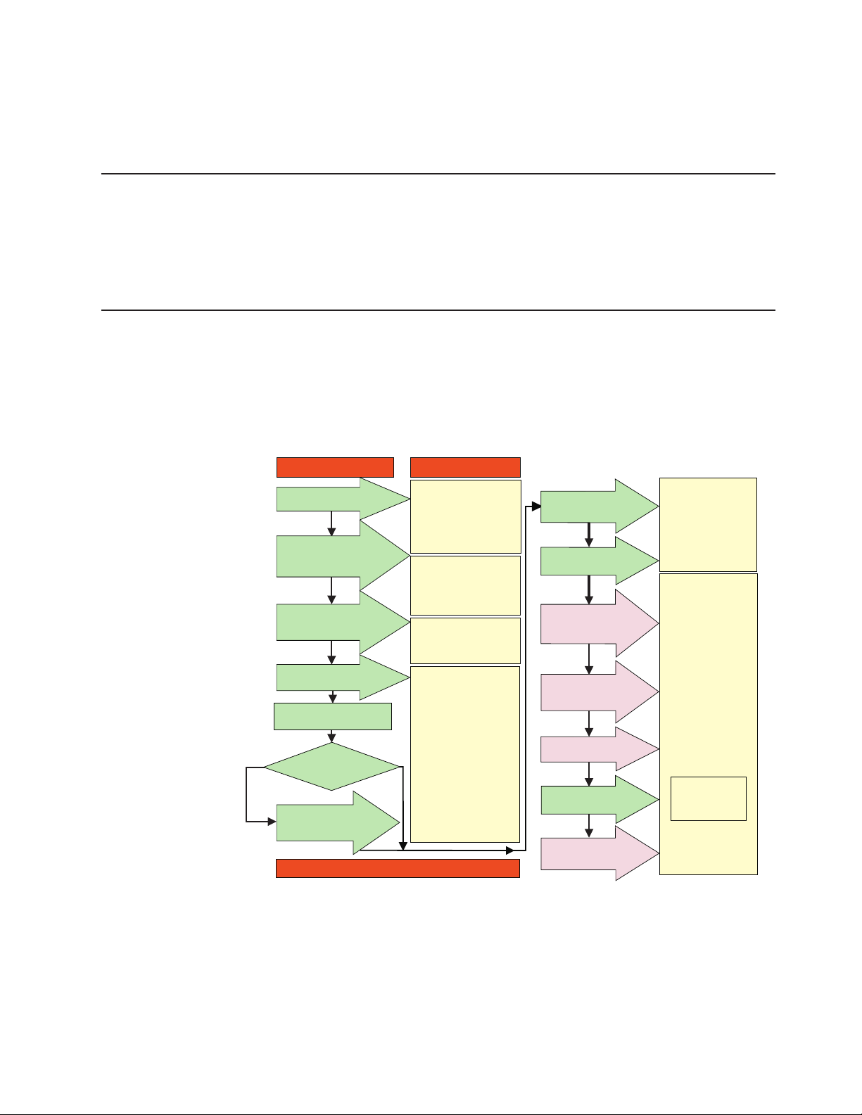
DS4000 installation process overview
The following flow chart gives an overview of the DS4000 hardware and the
DS4000 Storage Manager software installation process. Lined arrows in the flow
chart indicate consecutive steps in the hardware and software installation process.
Labeled arrows indicate which current documents provide detailed information about
those steps.
Install Process Documentation
Plan installation
Install Storage
Server/RAID Controller
Enclosure(s) in Rack
Install Storage
Expansion Unit(s)
* FC Planning and
Integration: User's Guide
and Svc Info
DS4000 Storage Manager
Concepts Guide
DS4000 Storage Svr
Installation Guide
DS4000 RAID Controller
Enclosure Unit Install
and User's Guide
DS4000 Storage Exp Units
Install and User's Guides
Connect Power and
Start Server
Verify Server
operation w/ LEDs
Prepare for
Installation of
SM Software
DS4000 Storage Server
Installation Guide
DS4000 Hardware
Maintenance Manual
DS4000 Problem
Determination Guide
DS4000 Storage
Manager Installation
and Support
OS Guides
Make FC Connections
Install and Verify
SM SW on Host and
DS4000 and HBA Install
and User's Guides
DS4000 Fibre Channel
Storage Server
Installation Guides
Fibre Channel Cabling
Instructions
Complete SM SW
Configure Storage
Out-of-Band
SET Link Speed
(1GB or 2GB)
Determine
Management
Method
In-Band
Install Network
Hardware; Prep are
Network Connection
Configure Storage
* For pSeries Server and 6227 or 6228 HBA use only
Subsystems on Host
Figure 1. Installation process flow by current publications
Workstation
Installation
Hardware
DS4000 Storage Manager
Copy Services
User's Guide
Online Help
About this document xix
sj001046
Page 22

DS4000 Storage Server publications
The following tables present an overview of the DS4500, DS4400, DS4300 Fibre
Channel, and DS4100 SATA Storage Server product libraries, as well as other
related documents. Each table lists documents that are included in the libraries and
what common tasks they address. Click on active links in the tables to access those
documents currently available on the Internet. You can access documentation for
the other DS4000 products at the following Web site:
www-1.ibm.com/servers/storage/support/disk/
You can also search for IBM publications at the following Web site:
www.ibm.com/shop/publications/order/
DS4500 storage server library
Table 2 associates each document in the DS4500 (previously FAStT900) storage
server library with its related common user tasks.
Table 2. TotalStorage DS4500 storage server document titles by user tasks
Title User Tasks
IBM TotalStorage
FAStT900
Installation and
Support Guide,
GC26-7530
IBM TotalStorage
FAStT900 Fibre
Channel Cabling
Instructions,
24P8135
IBM TotalStorage
FAStT900 Storage
Server User’s
Guide, GC26-7534
IBM TotalStorage
FAStT FC2-133 Dual
Port Host Bus
Adapter Installation
and User’s Guide,
GC26-7532
IBM FAStT FC2-133
Host Bus Adapter
Installation and
User’s Guide,
48P9823
IBM TotalStorage
FAStT Rack
Mounting
Instructions,
19K0900
Planning Hardware
Installation
U U U
U U
U U
U U
U U
Software
Installation
Configuration Operation and
U U U
Administration
Diagnosis and
Maintenance
xx IBM TotalStorage DS4100 Storage Server: Installation, User’s, and Maintenance Guide
Page 23

Table 2. TotalStorage DS4500 storage server document titles by user tasks (continued)
Title User Tasks
Planning Hardware
Installation
Software
Installation
Configuration Operation and
Administration
IBM FAStT
Management Suite
Java User’s Guide,
32P0081
IBM TotalStorage
DS4000 Hardware
Maintenance
Manual, GC26-7702
IBM TotalStorage
DS4000 Problem
Determination
Guide, GC26-7703
Diagnosis and
Maintenance
U U
U
U
About this document xxi
Page 24

DS4400 storage server library
Table 3 associates each document in the DS4400 (previously FAStT700) storage
server library with its related common user tasks.
Table 3. TotalStorage DS4400 storage server document titles by user tasks
Title User Tasks
IBM FAStT700 Fibre
Channel Cabling
Instructions,
32P0343
IBM FAStT700 Fibre
Channel Storage
Server User’s
Guide, 32P0341
IBM FAStT FC2-133
Dual Port Host Bus
Adapter Installation
and User’s Guide,
GC26-7532
IBM TotalStorage
FAStT FC2-133 Host
Bus Adapter
Installation and
User’s Guide,
48P9823
IBM FAStT
Management Suite
Java User’s Guide,
32P0081
IBM TotalStorage
DS4000 Hardware
Maintenance
Manual, GC26-7702
IBM TotalStorage
DS4000 Problem
Determination
Guide, GC26-7703
Planning Hardware
Installation
U U
U U
U U
Software
Installation
Configuration Operation and
U U U
Administration
U U
Diagnosis and
Maintenance
U
U
xxii IBM TotalStorage DS4100 Storage Server: Installation, User’s, and Maintenance Guide
Page 25

DS4300 storage server library
Table 4 associates each document in the DS4300 (previously FAStT600) storage
server library with its related common user tasks.
Table 4. TotalStorage DS4300 storage server document titles by user tasks
Title User Tasks
IBM TotalStorage
FAStT600 Fibre
Channel Storage
Server Installation
and User’s Guide,
GC26-7531
IBM TotalStorage
DS4000 Hardware
Maintenance
Manual, GC26-7702
IBM TotalStorage
DS4000 Problem
Determination
Guide, GC26-7703
IBM TotalStorage
FAStT FC2-133 Host
Bus Adapter
Installation and
User’s Guide,
48P9823
IBM TotalStorage
FAStT FC2-133 Dual
Port Host Bus
Adapter Installation
and User’s Guide,
GC26-7532
IBM TotalStorage
FAStT600 Rack
Mounting
Instructions,
24P8125
IBM TotalStorage
FAST600 Fibre
Channel Cabling
Instructions,
24P8126
Planning Hardware
Installation
U U U
U U
U U
U U
U U
Software
Installation
Configuration Operation and
Administration
Diagnosis and
Maintenance
U
U
DS4100 storage server library
Table 5 on page xxiv associates each document in the DS4100 (previously
FAStT100) storage server library with its related common user tasks.
About this document xxiii
Page 26

Table 5. TotalStorage DS4100 storage server document titles by user tasks
Title User Tasks
Planning Hardware
Installation
Software
Installation
Configuration Operation and
IBM TotalStorage
DS4100 Installation,
User’s, and
U U U U
Maintenance Guide,
GC26-7712
IBM TotalStorage
DS4100 Fibre
Channel Cabling
U U
Instructions,
25R0325
IBM TotalStorage
FAStT FC2-133 Dual
Port Host Bus
Adapter Installation
U U
and User’s Guide,
GC26-7532
IBM FAStT FC2-133
Host Bus Adapter
Installation and
U U
User’s Guide,
48P9823
IBM TotalStorage
DS4000 Hardware
Maintenance
Manual, GC26-7702
IBM TotalStorage
DS4000 Problem
Determination
Guide, GC26-7703
Administration
Diagnosis and
Maintenance
U
U
xxiv IBM TotalStorage DS4100 Storage Server: Installation, User’s, and Maintenance Guide
Page 27

DS4000-related hardware publications
Table 6 associates each of the following documents related to DS4000 (previously
FAStT) operations with its related common user tasks.
Table 6. TotalStorage DS4000-related document titles by user tasks
Title User Tasks
IBM Safety
Information,
P48P9741
IBM TotalStorage
FAStT Quick Start
Guide, GC26-7662
IBM TotalStorage
DS4000 Fibre
Channel and Serial
ATA Intermix
Premium Feature
Installation Overview
GC26-7713
IBM TotalStorage
DS4000 EXP100
Storage Expansion
Unit Installation,
User’s, and
Maintenance Guide,
GC26-7694
Fibre Channel
Solutions - IBM
FAStT EXP500
Installation and
User’s Guide,
59P5637
IBM TotalStorage
FAStT EXP700 and
EXP710 Storage
Expansion Units
Installation, User’s,
and Maintenance
Guide, GC26-7647
IBM TotalStorage
DS4000 Hard Drive
and Storage
Expansion
Enclosure
Installation and
Migration Guide,
GC26-7704
IBM Fibre Channel
SAN Configuration
Setup Guide,
25P2509
Planning Hardware
Installation
U U
U U U
U U U U U
U U U U U
U U U U U
U U
U U U U
Software
Installation
Configuration Operation and
Administration
U
Diagnosis and
Maintenance
About this document xxv
Page 28

Table 6. TotalStorage DS4000-related document titles by user tasks (continued)
Title User Tasks
Planning Hardware
Installation
Software
Installation
Configuration Operation and
IBM FAStT Host
Adapter Installation
and User’s Guide,
U U
59P5712
RS/6000 Eserver
pSeries Fibre
Channel Planning
and Integration:
U U U U
User’s Guide and
Service Information,
SC23-4329
DS4000 Storage Manager Version 9 publications
Table 7 associates each document in the DS4000 Storage Manager (previously
FAStT Storage Manager) library with its related common user tasks.
Table 7. TotalStorage DS4000 Storage Manager Version 9 titles by user tasks
Title User Tasks
IBM TotalStorage
DS4000 Storage
Manager Version 9
Installation and
Support Guide for
Windows
2000/Server 2003,
NetWare, ESX
Server, and Linux,
GC26-7706
IBM TotalStorage
DS4000 Storage
Manager Version 9
Installation and
Support Guide for
AIX, UNIX, Solaris
and Linux on
POWER,
GC26–7705
IBM TotalStorage
DS4000 Storage
Manager Version 9
Copy Services
User’s Guide,
GC26-7707
IBM TotalStorage
FAStT Storage
Manager Version 9
Concepts Guide,
GC26-7661
Planning Hardware
Installation
U U U
U U U
U U U U
U U U U U U
Software
Installation
Configuration Operation and
Administration
Administration
Diagnosis and
Maintenance
Diagnosis and
Maintenance
xxvi IBM TotalStorage DS4100 Storage Server: Installation, User’s, and Maintenance Guide
Page 29

Getting information, help, and service
If you need help, service, or technical assistance or just want more information
about IBM products, you will find a wide variety of sources available from IBM to
assist you. This section contains information about where to go for additional
information about IBM and IBM products, what to do if you experience a problem
with your IBM Eserver xSeries
™
service, if it is necessary.
Before you call
Before you call, make sure that you have taken these steps to try to solve the
problem yourself:
v Check all cables to make sure that they are connected.
v Check the power switches to make sure that the system is turned on.
v Use the troubleshooting information in your system documentation and use the
diagnostic tools that come with your system.
v Check for technical information, hints, tips, and new device drivers at the
following Web site:
www.ibm.com/storage/techsup.htm
v Use an IBM discussion forum on the IBM Web site to ask questions.
or IntelliStation system, and whom to call for
can solve many problems without outside assistance by following the
You
troubleshooting procedures that IBM provides in the online help or in the documents
that are provided with your system and software. The information that comes with
your system also describes the diagnostic tests that you can perform. Most xSeries
and IntelliStation systems, operating systems, and programs come with information
that contains troubleshooting procedures and explanations of error messages and
error codes. If you suspect a software problem, see the information for the
operating system or program.
Using the documentation
Information about the xSeries or IntelliStation system and preinstalled software, if
any, is available in the documents that come with your system. This includes printed
documents, online documents, readme files, and help files. See the troubleshooting
information in your system documentation for instructions on how to use the
diagnostic programs. The troubleshooting information or the diagnostic programs
might tell you that you need additional or updated device drivers or other software.
Web sites
IBM maintains pages on the World Wide Web where you can get the latest
technical information and download device drivers and updates.
v For DS4000 information, go to the following Web site:
www.ibm.com/storage/techsup.htm
The support page has many sources of information and ways for you to solve
problems, including:
– Diagnosing problems using the IBM Online Assistant
– Downloading the latest device drivers and updates for your products
– Viewing frequently asked questions (FAQ)
– Viewing hints and tips to help you solve problems
– Participating in IBM discussion forums
– Setting up e-mail notification of technical updates about your products
About this document xxvii
Page 30

v Yo u can order publications through the IBM Publications Ordering System at the
following web site:
www.elink.ibmlink.ibm.com/public/applications/publications/cgibin/pbi.cgi/
v For the latest information about IBM xSeries products, services, and support, go
to the following Web site:
www.ibm.com/eserver/xseries/
v For the latest information about IBM pSeries products, services, and support, go
to the following Web site:
www.ibm.com/eserver/pseries/
v For the latest information about the IBM IntelliStation information, go to the
following Web site:
www-132.ibm.com/content/home/store_IBMPublicUSA/
en_US/IntelliStation_workstations.html
v For the latest information about operating system and HBA support, clustering
support, SAN fabric support, and Storage Manager feature support, see the
TotalStorage DS4000 Interoperability Matrix at the following Web site:
www.storage.ibm.com/disk/fastt/supserver.htm
Software service and support
Through IBM Support Line, for a fee you can get telephone assistance with usage,
configuration, and software problems with xSeries servers, IntelliStation
workstations, and appliances. For information about which products are supported
by Support Line in your country or region, go to the following Web site:
www.ibm.com/services/sl/products/
For more information about the IBM Support Line and other IBM services, go to the
following Web sites:
v www.ibm.com/services/
v www.ibm.com/planetwide/
Hardware service and support
You can receive hardware service through IBM Integrated Technology Services or
through your IBM reseller, if your reseller is authorized by IBM to provide warranty
service. Go to the following Web site for support telephone numbers:
www.ibm.com/planetwide/
In the U.S. and Canada, hardware service and support is available 24 hours a day,
7 days a week. In the U.K., these services are available Monday through Friday,
from 9 a.m. to 6 p.m.
Fire suppression systems
A fire suppression system is the responsibility of the customer. The customer’s own
insurance underwriter, local fire marshal, or a local building inspector, or both,
should be consulted in selecting a fire suppression system that provides the correct
level of coverage and protection. IBM designs and manufactures equipment to
internal and external standards that require certain environments for reliable
operation. Because IBM does not test any equipment for compatibility with fire
suppression systems, IBM does not make compatibility claims of any kind nor does
IBM provide recommendations on fire suppression systems.
xxviii IBM TotalStorage DS4100 Storage Server: Installation, User’s, and Maintenance Guide
Page 31

Table 9 on page 14 lists the environmental specifications for the DS4100.
How to send your comments
Your feedback is important in helping us to provide the most accurate and
high-quality information. If you have comments or suggestions for improving this
publication, you can send us comments electronically by using these addresses:
v Internet: starpubs@us.ibm.com
v IBMLink from U.S.A.: STARPUBS at SJEVM5
v IBMLink from Canada: STARPUBS at TORIBM
v IBM Mail Exchange: USIB3WD at IBMMAIL
can also mail your comments by using the Reader Comment Form in the back
You
of this manual or direct your mail to:
International Business Machines Corporation
Information Development
Dept. GZW
9000 South Rita Road
Tucson, AZ 85744–0001
U.S.A.
About this document xxix
Page 32

xxx IBM TotalStorage DS4100 Storage Server: Installation, User’s, and Maintenance Guide
Page 33

Chapter 1. Introduction
This chapter describes the operating specifications, features, and components for
the IBM TotalStorage DS4100 storage server (hereafter referred to as DS4100 or
storage server). This chapter also includes a list of hardware that comes with the
storage server.
Overview
IBM DS4000 solutions support the large and growing data storage requirements of
business-critical applications. These scalable IBM DS4000 solutions offer you data
access and protection to meet your existing enterprise storage requirements and
prepare for the future.
Designed for data archival, data reference, and near-line storage applications, the
DS4100 utilizes the latest Serial Advanced Technology Attachment (SATA) disk
drive technology. The DS4100 supports up to fourteen 1.5 Gbps 250 GB SATA disk
drive modules, offering up to 3.5 terabytes (TB) of capacity per enclosure.
Note: SATA hard drive CRUs cannot be interchanged with the fibre-channel hard
drive CRUs that are supported in other DS4000 storage products.
The DS4100 can be used in storage area networks to satisfy the needs of various
fixed content, data-reference applications that require large amounts of storage
capacity but do not have the high utilization and access characteristics satisfied by
fibre channel disk drive storage. The storage server provides continuous, reliable
service, using hot-swap technology for easy replacement without shutting down the
system.
IBM currently offers two versions of the DS4100:
v DS4100 base storage server (Machine Type 1724, Model 100)
v DS4100 single-controller storage server (Machine Type 1724, Model 1Sx)
About the DS4100 base storage server
The DS4100 base (dual-controller) storage server (Machine Type 1724, Model 100)
is a rack-mountable storage server that comes with two RAID controllers, two power
supplies, and two cooling units. It provides dual, redundant controllers, redundant
cooling, redundant power, and battery backup of the RAID controller cache. The
DS4100 base storage server is designed to provide maximum host and drive-side
redundancy, enabling full redundant drive loop support to additional disk storage
capacity in the drive expansion enclosures via the drive loop port from each RAID
controller. In addition, each RAID controller supports direct attachment of two hosts
that contain two fibre channel host bus adapters each. External cables and small
form-factor pluggable (SFP) modules connect the storage server to the storage
expansion unit and the host servers.
Up to seven DS4000 EXP100 storage expansion units can be connected together
with the DS4100 base storage server in a fibre-channel loop, providing connections
to a maximum of 112 hard drives. With the DS4100 base storage server, you can
configure RAID-protected storage solutions of up to 28 TB (by connecting the
DS4100 base storage server to seven drive expansion enclosures with 250 GB
SATA hard drives), providing economical and scalable storage for your rapidly
growing application needs for limited access, data reference storage capacity. The
DS4100 base storage server is designed with redundant 2 Gbps fibre channel
© Copyright IBM Corp. 2004 1
Page 34

connections for expanding the DS4100 storage capacity to SATA hard drives in
external DS4000 EXP100 storage expansion units.
Currently, the only DS4000 storage expansion unit model that can be attached to
the DS4100 base storage server is the DS4000 EXP100. Do not connect other
DS4000 storage expansion units (such as the DS4000 EXP700 or DS4000
EXP710) to the DS4100 base storage server. Please contact your IBM support
representative for information about the availability of future support for connecting
other DS4000 storage expansion unit models.
Note: You must make fibre channel connections from the host server fibre channel
HBA ports to both controllers in the DS4100 base storage server to ensure
full host-side redundancy.
Attention
To ensure proper operation when connecting DS4000 EXP100 expansion units
to the DS4100 base storage server, you must verify that the DS4000 EXP100
ESM firmware level is at level 9554 or later. If the ESM firmware level is lower
than 9554, disconnect the DS4000 EXP100 and contact IBM support, your
IBM reseller, or your IBM representative for assistance.
About the DS4100 single-controller storage server
The DS4100 single-controller storage server (Machine Type 1724, Model 1Sx,
where x represents an upper-case alphanumeric character) is a rack-mountable
storage server that comes with one RAID controller, one power supply, and two
cooling units. It supports up to fourteen hot-swap internal disk drive slots, which
support over 3.5 TB of storage capacity when using 250 GB SATA disk drives.
External cables and small form-factor pluggable (SFP) modules connect the storage
server to the host server fibre channel HBA ports.
Notes:
1. The DS4100 single-controller storage server does not support storage capacity
expansion using external DS4000 EXP100 expansion units (or any other models
of DS4000 storage expansion units). In addition, it does not offer RAID
controller and drive loop redundancy.
2. The cache in the controller of the DS4100 single-controller storage server is
used for read operations only. No write operations will be cached.
The following limitations apply to this release of the DS4100 single-controller
storage server.
v All factory-delivered DS4100 RAID controllers are shipped with a recent version
of controller firmware loaded on the RAID controller, but that firmware version
might not match precisely the firmware version the RAID controller you need to
replace. When you replace the RAID controller in the DS4100 single-controller
storage server, if the firmware version of the replacement RAID controller is
determined to be incompatible with the configuration database during the boot
process, the DS4100 single-controller storage server will enter a Stop State and
will not allow any DS4000 Storage Manager operations to be performed. In this
case, you must manually upgrade or downgrade the replacement RAID controller
firmware to match the version required by the configuration database. See
“Manually upgrading the firmware for the DS4100 single-controller storage
server” on page 103.
2 IBM TotalStorage DS4100 Storage Server: Installation, User’s, and Maintenance Guide
Page 35

v The DS4100 single-controller storage server does not support automatic firmware
updates. All firmware upgrades and downgrades for the DS4100 single-controller
storage server must be performed manually, as described in “Manually upgrading
the firmware for the DS4100 single-controller storage server” on page 103.
v All DS4100 single-controller storage server controller firmware updates must be
performed off-line.
v Yo u cannot upgrade from the DS4100 single-controller storage server to the
DS4100 base storage server. Please contact your IBM reseller or representative
for the possible availability of such support in the future.
Fibre channel defined
Fibre channel technology is outlined in the SCSI-3 Fibre Channel Protocol
(SCSI-FCP) standard. Fibre channel is a high-speed data transport technology that
is used for mass storage and networking.
Using a fibre-channel arbitrated loop (FC-AL), more than 100 fibre-channel devices
can be supported, compared to 15 small computer system interface (SCSI) devices.
The connection from the DS4100 base storage server to the DS4000 EXP100 drive
expansion enclosure ports or fibre channel host bus adapter ports is a 2 Gb
fibre-channel device that supports data transfer rates up to 200 MBps half-duplex
and 400 MBps full-duplex on optical interfaces.
1
SATA defined
The Serial Advanced Technology Attachment (S ATA) interface offers increased data
rate performance over Parallel Advanced Technology Attachment (ATA), while
maintaining the benefits of ATA. SATA is designed to overcome the performance
barriers that have been forecasted for current parallel technologies while
maintaining the cost-efficiency of Parallel ATA . SATA specifications allow for thinner,
more flexible cables, and lower pin counts. It also enables easier, more flexible
cable routing management and the use of smaller connectors than is possible with
the existing Parallel ATA technology.
The Serial ATA Working Group introduced the first SATA specification, Serial ATA
1.0, in 2001 (http://www.serialata.org).
Product updates
You should download the latest version of the DS4000 Storage Manager host
software and the DS4000 storage server controller firmware and drive firmware
(and, if you are connecting DS4000 EXP100 expansion units to the DS4100 base
storage server storage server, the DS4000 EXP100 ESM firmware, and the DS4000
EXP100 disk drive firmware) at the time of the initial installation and when product
updates become available.
To be notified of important product updates, you must first register at the IBM
Support and Download Web site:
www-1.ibm.com/servers/storage/disk/
1. For the DS4100, each drive is considered to be a device in a fibre-channel loop, even though the DS4100 drive interface is S ATA
(not fibre channel). The DS4000 EXP100 ESM and the DS4100 controller and S ATA hard drive interposer convert S ATA interface
protocol to fibre channel protocol.
Chapter 1. Introduction 3
Page 36

Go to the Personalized Support section of the web page and click My Support.
On the next page, go to the We use IBM Registration section. To register to use
this site, click Register.
Perform the following steps to receive product updates:
1. Once you have registered, type your user ID and password to log into the site.
The Welcome page opens.
2. In the Select a Product Family pull-down menu, scroll down to the listing of
hardware topics and select Computer Storage. Click Go. The Computer
Storage page opens.
3. Scroll down to the Disk Storage Systems category and check the box for 1724
(and 1710 if you are connecting DS4000 EXP100 expansion units to the
DS4100). Check the boxes for any other DS4000 products for which you would
like to receive information. Scroll to the bottom of the page and select Save and
Return. The main page opens.
4. Select your mail preferences. Select Flashes and Downloadable files to
receive important information about product updates. Click Submit. You should
see a confirmation at the bottom of the page that indicates that your profile was
successfully updated.
Features at a glance
Table 8 summarizes the features of the storage server. For a list of the operating
specifications, such as weight, height, and heat output, see Table 9 on page 14.
Table 8. Features at a glance
General
v Modular components:
– High-capacity SATA disk drives
– RAID controllers
– Power supplies
– Cooling fans
v Technology:
– Support for disk arrays
– Support for clustering
– Fibre channel host interface
– Redundant data storage, RAID
controllers, and power system (base
storage server only)
– Hot-swap technology for drives and
fans
– Hot-swap technology for RAID
controllers and power supplies (base
storage server only)
– DS4100 single-controller has a
non-redundant hard disk drive
interface, power supply, and RAID
controller. However, it does offer a
redundant cooling system.
Attention:
You will lose access to data if
you attempt to hot-swap the controller or
power-supply components in a DS4100
single-controller storage server.
v User interface:
– Built-in power, activity, and fault light
emitting diodes (LEDs)
– Identification labeling on customer
replaceable units (CRUs), rear LEDs,
switches, and connectors
– Easy-to-replace drives, power
supplies, RAID controllers, and fans
drive storage
Disk
1.5 Gbps SATA hard disk drives
Maximum drives per storage server: 14
Attached
Expansion Units (base
storage server only)
2 Gbps connections only
RAID controllers
v Technology and interfaces:
– Fibre channel: 40-pin fibre channel
disk drives
– Fibre channel interface:
- For base storage server: six
small form-factor pluggable (SFP)
ports for incoming and outgoing
fibre-channel cables (three SFP
ports on each RAID controller)
- For single-controller storage
server: three SFP ports for
incoming and outgoing
fibre-channel cables
Note: The SFP port labelled
Expansion is not active).
Two 1 Gbps/2 Gbps
–
(auto-negotiated) fibre channel host
side connections per controller
4 IBM TotalStorage DS4100 Storage Server: Installation, User’s, and Maintenance Guide
Page 37

Clustering support
Clustering is a means of sharing array groups among controllers to provide
redundancy of controllers and servers. This redundancy is important if a hardware
component fails. If a hardware component failure occurs in a cluster, another server
takes ownership of the array group.
Clustering requires software specific to your operating system. For more information
about clustering, go to the following Web site:
www.pc.ibm.com/us/compat/nos/matrix.shtml
Inventory checklist
After you unpack the DS4100 storage server, verify that you have the following
items:
v Hardware
– Up to 14 hard disk drives (shipped installed in the DS4100)
– RAID controllers (shipped installed in the DS4100)
The DS4100 base storage server is shipped with no SATA hard disk
Note:
drives as standard. You can order the unit with up to 14 250 GB SATA
drive CRUs installed at the factory. The DS4100 single-controller
storage server is shipped with three 250 GB SATA drive CRUs as
standard. Yo u can order the unit with up to 11 additional SATA drive
CRUs installed at the factory.
- 2 controllers on the base storage server
- 1 controller on the single-controller storage server
A blank controller tray is installed in the empty controller slot in the
Note:
DS4100 single-controller storage server chassis. For proper cooling
and EMI shielding, do not remove this blank controller tray.
Two fan units (shipped installed in the DS4100)
–
– Power supplies (shipped installed in the DS4100)
- 2 power supplies on the base storage server
- 1 power supply on the single-controller storage server
A blank power supply tray is installed in the empty power supply slot
Note:
in the DS4100 single-controller storage server chassis. For proper
cooling and EMI shielding, do not remove this blank power supply
tray.
Line cord jumpers
–
- 2 line cord jumpers on the base storage server
- 1 line cord jumper on the single-controller storage server
Line cord jumpers are power cords used to connect the DS4100 power supply
units to the IBM-certified rack power distribution units (PDUs).
– One rack-mounting hardware kit, including:
- Two rails (right and left assembly)
- Eight M6 black hex-head slotted screws
- Eight M6 cage nuts
- Eight M6 clip nuts
– Up to 14 blank drive trays (shipped installed in the DS4100)
Chapter 1. Introduction 5
Page 38

Your DS4100 storage server has 14 hard disk drive slots; any drive slots not
containing hard disk drives will contain blank drive trays. Each of the 14 drive
slots must always contain either a blank tray or a hard disk drive.
– Box ID labels (used to label the storage server IDs on the front of the
DS4100)
– Wrap plug and coupler kit
Attention: The DS4100 does not ship with region-specific power cords. You
must obtain the IBM-approved power cords for your region. See Appendix C,
“Power cords,” on page 125 for the IBM-approved power cords for your region.
v Software and documentation
– DS4000 Storage Manager Version 9.10 Support CD, including client software
and firmware, and online help and publications in Adobe Acrobat Portable
Document Format (PDF)
For a list of available IBM DS4000 publications, see “DS4000 Storage Server
publications” on page xx.
– IBM TotalStorage DS4100 Storage Server Installation, User’s, and
Maintenance Guide
– IBM TotalStorage DS4100 Fibre Channel Cabling Instructions
– IBM Safety Information
– IBM TotalStorage Storage Server and Expansion Unit Quick Start Guide
– IBM License Agreement
– Statement of Limited Warranty
If an item is missing or damaged, contact your IBM reseller or your IBM marketing
representative.
If you have not already done so, record your storage server serial number in the
table in Appendix A, “Records,” on page 119. The serial number is located on a
label at the rear of the DS4100. The machine and model number are found on the
product information label above the serial number.
A rack mounting template and instructions for installing the support rails and the
storage server are provided in this document in Chapter 2, “Installing the storage
server,” on page 17.
To connect your DS4100 to other devices, use the following options:
v IBM SFP module
v IBM LC-LC fibre-channel cable
v IBM LC-SC fibre-channel cable (for host-side connections only)
You must order these options separately.
Note:
Best practices guidelines
To ensure optimal operation of your system, always follow these best practices
guidelines:
v Back up the data on your storage drives periodically.
v DS4100 base storage server only: To maintain power redundancy, plug the
DS4100 storage server’s right and the left power supplies into two independent
external power circuits through ac distribution units inside a rack cabinet or
directly into external receptacles. Similarly, the right and left power supplies of
6 IBM TotalStorage DS4100 Storage Server: Installation, User’s, and Maintenance Guide
Page 39

the DS4000 storage expansion units attached to the DS4100 storage server
should be plugged into the same two independent external power circuits as the
DS4100. This ensures that the DS4100 storage server and all its attached
storage expansion units will have power if only one power circuit is available. In
addition, having all the right or all the left power supplies plug into the same
power circuit enables the components in the storage subsystem to power on
simultaneously during an unattended restoration of power. See Figure 56 on
page 62 for an example of redundant power connections.
This guideline cannot be followed for the DS4100 single-controller storage
Note:
server, which does not offer redundant power supplies. However, you can
use Uninterruptible Power Supply (UPS) units with the DS4100
single-controller storage server to provide protection against power
brown-outs and short power outages.
v Before any planned system shutdown or after any system additions, removals, or
modifications (including logical drive creations, storage partitioning definitions,
hardware changes, and so on), save the storage subsystem profile as explained
in the DS4000 Storage Manager guide for your operating system. Save the
profile in a location other than the logical drives created for the DS4100 storage
server.
v Ensure that your system is in an optimal state before you shut it down. Never
turn the power off if any fault light is lit; be sure to resolve any error conditions
before you shut down the system.
v During any maintenance or attended power-up procedure, carefully follow the
power-up sequence listed in “Turning on the storage server” on page 66. Check
that each component of the subsystem is powered-on in the proper order during
this entire power-up procedure to ensure the controller will be able to optimally
access all of your storage subsystems.
v The storage subsystem supports simultaneous power-up to the system
components; however, you should always follow the power-up sequence listed in
“Turning on the storage server” on page 66 during any attended power-up
procedure.
v A storage system in an optimal state should recover automatically from an
unexpected shutdown and unattended simultaneous restoration of power to
system components. After power is restored, call IBM support if any of the
following conditions occur:
– The storage subsystem logical drives and arrays are not displayed in the
DS4000 Storage Manager graphical user interface (GUI).
– The storage subsystem logical drives and arrays do not come online.
– The storage subsystem logical drives and arrays seem to be degraded.
Storage server components
The following sections show the components of the DS4100 storage server.
Hot-swappable devices enable you to maintain the availability of your system while
you remove, install, or replace a hot-swap device. All DS4100 storage server
models support hot-swap SATA hard disk drives and cooling fan CRUs, so you can
remove and replace these components without turning off the storage server. In
addition, the DS4100 base storage server supports hot-swap RAID controllers and
power supplies.
Chapter 1. Introduction 7
Page 40
Attention: The DS4100 single-controller storage server does not support
hot-swap RAID controllers or power supplies. You will lose access to data if you
attempt to remove or replace a functioning (non-failed) RAID controller or power
supply in a DS4100 single-controller storage server without first powering down the
storage server.
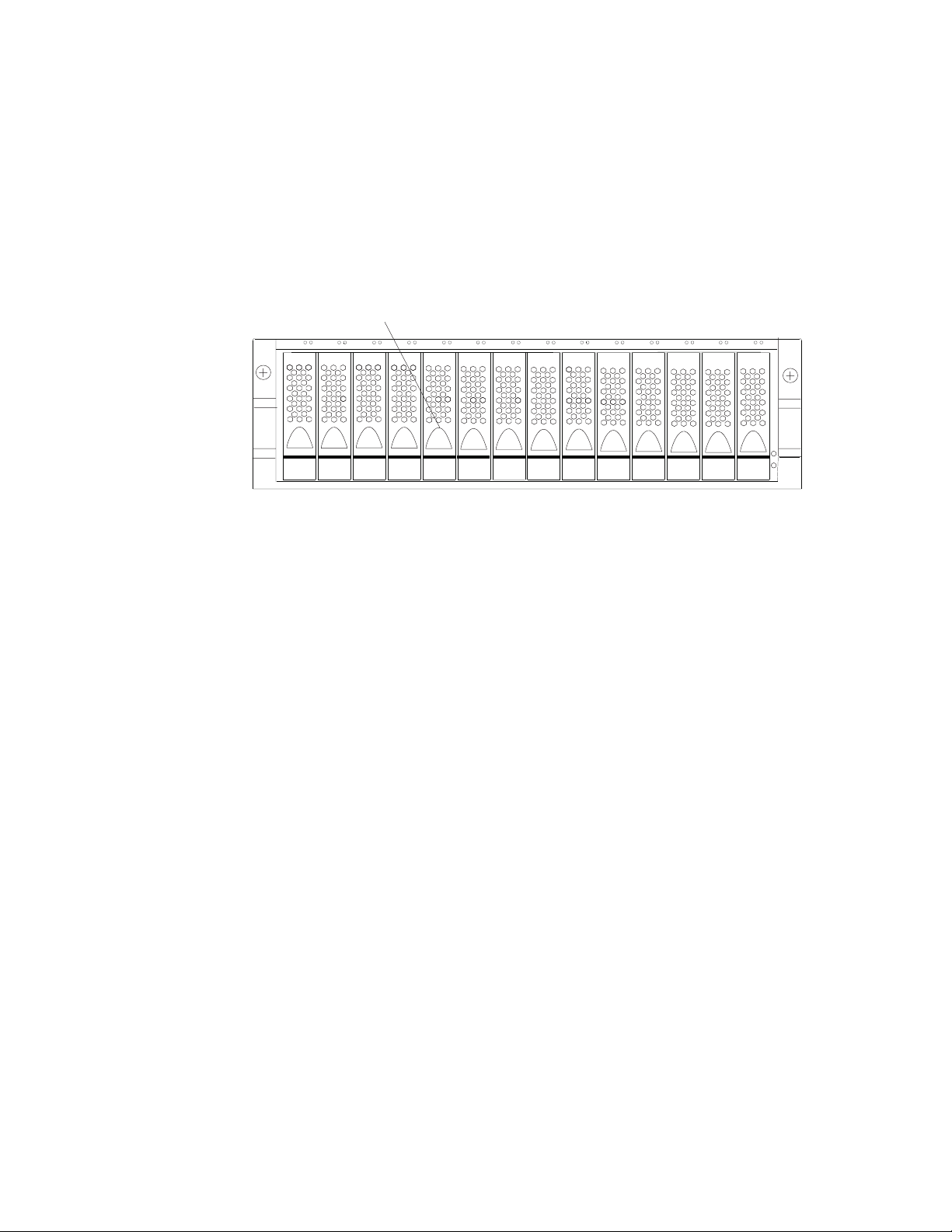
Hot-swap drive bays
The hot-swap drive bays that are accessible from the front of your storage server
are shown in Figure 2.
Hot-swap drive bays
f10ug052
Figure 2. DS4100 hot-swap drive bays
The DS4100 supports up to 14 DS4000 1.5 Gbps SATA hard disk drives. These
drives are preinstalled in drive trays. The unit consisting of the drive and the drive
carrier assembly is called a drive CRU. The SATA drive CRU includes the drive tray,
the S ATA drive, and the hard disk drive (HDD) interposer card. You install the drive
CRUs in the 14 drive bays on the front of the storage server. There are no
serviceable parts in a drive CRU. If it fails, it must be replaced in its entirety (drive,
interposer, bezel, and tray).
Attention:
1. Never hot-swap a drive CRU when its associated green Activity LED is flashing.
Hot-swap a drive CRU only when its associated amber Fault LED lights and is
not flashing or when the drive is inactive and its associated green Activity LED
lights and is not flashing.
2. The SATA drive and its HDD card are digitally signed together at the factory. Do
not swap drives and interposers between drive CRUs. Do not replace one SATA
drive with another SATA drive. These actions will result in a drive CRU that
cannot be recognized by the storage server RAID controller.
3. After you remove a drive CRU, wait at least 70 seconds before replacing or
reseating the drive CRU to allow the drive to properly spin down. Failure to do
so may cause undesired events.
If the hard disk drive you want to remove is not in a failed or bypass state,
Note:
always use the DS4000 Storage Manager client program either to place the
drive in a failed state or to place the array that is associated with the drive
(or drives) in an offline state before you remove the drive from the enclosure.
Front controls and indicators
This section describes the primary controls on the front of the storage server. The
locations of these primary controls are shown in Figure 3 on page 9.
8 IBM TotalStorage DS4100 Storage Server: Installation, User’s, and Maintenance Guide
Page 41

Activity LED
LatchTray handle
Fault LED
General system
error LED
Power-on LED
Figure 3. Front controls and indicators
The DS4100 has blank trays in the unused drive bays. To begin installing new
drives, you must first remove the blank trays and save them. Each of the 14 bays
must always contain either a blank tray or a drive CRU. Yo u can install up to 14
hot-swap drive CRUs in the storage server.
v Activity LED: Each drive CRU has an associated Activity LED on the DS4100
chassis. A flashing green LED indicates drive activity. A solid green LED indicates
that the drive is properly installed and powered on.
v Fault LED: Each drive CRU has an associated Fault LED on the DS4100
chassis. A solid amber LED indicates a drive failure. A flashing amber LED
indicates that a drive identify process is in progress.
v General system error LED: A solid amber LED indicates a power supply, fan
unit, or hard disk drive error. Use the DS4000 Storage Manager client to
diagnose and repair the problem. For more information, see “Checking the LEDs”
on page 71.
v Latch: Use this multipurpose latch to release or lock the drive CRU in place.
v Power-on LED: A solid green LED indicates that the storage server has dc
power.
v Tray handle: Use this multipurpose handle to insert and remove a drive CRU in
the bay.
f10ug053
Back view
Figure 4 on page 10 shows the components at the back of the DS4100 base
storage server.
Chapter 1. Introduction 9
Page 42

Hot-swap fan bays
Raid controllers
f10ug021
Hot-swap
power supplies
Figure 4. Back view of DS4100 base storage server
Figure 5 shows the components at the back of the DS4100 single-controller storage
server. The DS4100 single-controller storage server has a controller blank instead
of a second RAID controller and a power supply blank instead of a second power
supply.
Hot-swap fan bays
RAID controller
Power supply
Figure 5. Back view of DS4100 single-controller storage server
RAID controller
Each RAID controller contains three ports for Small Form-Factor Pluggable
(SFP) modules that connect to the fibre channel cables. Two of the SFP
ports (labelled Host 1 and Host 2) are for host server attachment. The third
SFP port (labelled Expansion) is used to connect additional expansion units
to the storage server.
Note: In the DS4100 single-controller storage server, the third SFP port
(labelled Expansion) is present but not active.
Each RAID controller also contains a battery to maintain cache data in the
event of a power failure. For more information, see “Cache memory and
RAID controller battery” on page 75.
Attention: Yo u will lose access to data if you attempt to hot-swap the RAID
controller in a DS4100 single-controller storage server.
Hot-swap fans
The storage server has two interchangeable hot-swap and redundant fan
CRUs. Each fan CRU contains two fans. If one fan CRU fails, the second
f10ug021b
10 IBM TotalStorage DS4100 Storage Server: Installation, User’s, and Maintenance Guide
Page 43

fan CRU continues to operate. Yo u must install both fan CRUs to maintain
proper cooling within the storage server, even if one fan CRU is not
operational.
Hot-swap power supplies
The DS4100 base storage server comes with two hot-swap power supplies.
You must install both power supplies to maintain proper cooling.
The DS4100 single-controller storage server storage server comes with one
power supply.
Attention: Yo u will lose access to data if you attempt to hot-swap the
power supply in a DS4100 single-controller storage server.
Interface ports and switches
Figure 6 shows the ports and switches on the back of the DS4100 base storage
server.
Ethernet
Host port 2
Host port 1
Expansion port
Serial port Serial port
Host port 2
Host port 1
Ethernet
Expansion port
1 Gbps/
AC power
connector
AC power
switch
Server ID
switch
2 Gbps
switch
AC power
connector
AC power
switch
Figure 6. Interface ports and switches for DS4100 base storage server
Figure 7 on page 12 shows the ports and switches on the back of the DS4100
single-controller storage server.
Note: The DS4100 single-controller storage server has a controller blank instead of
a second RAID controller and a power supply blank instead of a second
power supply.
f10ug022
Chapter 1. Introduction 11
Page 44

Ethernet
Host port 2
Expansion port (inactive in the DS4100
single-controller storage server)
Host port 1
AC power
connector
Serial port
AC power
switch
Server ID
switch
1 Gbps/
2 Gbps
switch
Figure 7. Interface ports and switches for DS4100 single-controller storage server
RAID controller
Each RAID controller contains several connectors and LEDs. Each
controller has two host ports and one expansion port for connecting the
storage server to hosts or expansion units. Yo u first insert SFPs into the
ports and then connect the fibre channel cables.
Host ports
The host ports (labelled Host 1 and Host 2) are used to connect a fibre
channel cable from the host systems. You first insert an SFP into the port
and then connect a fibre channel cable. The two host ports in each
controller are independent. They are not connected in the controller module
as they would be in a hub configuration. The host port connections can
auto-negotiate between 1 Gbps and 2 Gbps.
f10ug022scu
Ethernet port
The Ethernet port is used for an RJ-45 10BASE-T or 100BASE-T Ethernet
connection to each controller. Use the Ethernet connection to directly
manage the DS4100.
Expansion port
The expansion port (labelled Expansion) is used to connect additional
expansion units to the RAID controllers on the DS4100 base storage server.
You first insert an SFP into the port and then connect a fibre channel cable.
Note: In the DS4100 single-controller storage server, the expansion port on
port
Serial
The serial port is used by service personnel to perform diagnostic
operations on the RAID controllers. Incorrect use of the serial port can
result in loss of data access and, in some cases, in loss of data.
The maximum baud rate is 57 600 bps.
Note:
Server
ID switch (enclosure ID switch)
The server ID (also referred to as enclosure ID) switch settings range from
0 through 7. When connecting the DS4100 base storage server to DS4000
EXP100 storage expansion units, only the unique IDs ranging from 00
through 07 can be set.
the RAID controller is not active.
12 IBM TotalStorage DS4100 Storage Server: Installation, User’s, and Maintenance Guide
Page 45

Attention: When connecting the DS4100 to DS4000 EXP100 storage
expansion units, DO NOT use the tens digit (x10) setting. Use only the
ones digit (x1) setting to set unique server IDs or enclosure IDs. For more
information, see “Server ID (enclosure ID) settings” on page 33.
Gbps/2 Gbps switch
1
The default switch setting is 2 Gbps. This is the only speed setting that is
allowed for the DS4100.
Attention: Do not remove the metal plate that covers the storage server
speed setting. Do not adjust the storage server speed setting.
Storage server operating environment
This section provides general operating information about the DS4100. All
components plug directly into the backplane.
Chapter 1. Introduction 13
Page 46

DS4100 specifications
Table 9 lists the physical specifications for the DS4100.
Table 9. IBM TotalStorage DS4100 specifications
Size
v Width: 48.18 cm (18.97 in.)
v Height: 13.23 cm (5.21 in.)
v Depth: 59.74 cm (23.52 in.)
Weight
v Drive-ready weight (without disk drive
modules installed):
– Model 100: 26.64 kg (58.9 lb)
– Model 1Sx: 23.44 kg (51.9 lb)
Fully configured weight (with 14 disk drives
v
installed):
– Model 100: 40.36 kg (89 lb)
– Model 1Sx: 37.16 kg (82 lb)
Environment
v Air temperature
– Operating:
- Altitude: 0 - 914 m (3000 ft): 10° -
35° C (50° - 95° F)
- Altitude: 914 m - 2133 m (3000 -
7000 ft): 10° - 32° C (50° - 90° F)
Important:
The recommended
operating environment air temperature
is 22° C (72° F) or lower.
– Storage:
- Altitude: 0 - 914 m (3000 ft): 1° - 60°
C (33° - 140° F)
- Altitude: 914 m - 2133 m (3000 -
7000 ft): 1° - 57° C (33° - 135° F)
Humidity
v
Heat dissipation
v Fully configured storage server (14 1.5
Gbps SATA hard disk drives)
– 1235 BTU per hour
Acoustical
noise emission values
For open bay (0 drives installed) and typical
system configurations (eight hard disk drives
installed):
v Sound power (idling):
– 5.9 bel (open bay)
– 6.1 bel (typical)
Sound power (operating):
v
– 5.9 bel (open bay)
– 6.2 bel (typical)
Sound pressure (idling):
v
– 44 dBA (open bay)
– 46 dBA (typical)
Sound pressure (operating):
v
– 44 dBA (open bay)
– 47 dBA (typical)
These
levels are measured in controlled
acoustical environments according to ISO
7779 and are reported in accordance with
ISO 9296. The declared sound power levels
indicate an upper limit, below which a large
portion of machines operate. Sound pressure
levels in your location might exceed the
average 1-meter values stated because of
room reflections and other nearby noise.
– 8% - 80%
– Noncondensing
Notes:
1. The nonoperating environment must not exceed the operating environment
limits for longer than 60 days.
2. The storage environment must not exceed the operating environment limits for
longer than 1 year.
3. Substantial deviations from the suggested operating range, in either direction, if
sustained for extended periods of time, will expose the unit to greater risk of
failure from external causes.
The AC power sources must provide the correct voltage, current, and frequency
specified on the storage server. The storage server can run without interruption
within the limits shown in Table 10 on page 15.
14 IBM TotalStorage DS4100 Storage Server: Installation, User’s, and Maintenance Guide
Page 47

Table 10. IBM TotalStorage DS4100 AC power requirements
Nominal Voltage 90 to 136 VAC 180 to 264 VAC
Frequency 50 to 60 Hz 50 to 60 Hz
Idle Current 2.50 A
Maximum Operating Current 3.01 A
a.
Typical voltage: 115 V AC, 60 Hz at 77% power-supply efficiency and 0.96 power factor
b.
Typical voltage: 230 V AC, 60 Hz at 77% power-supply efficiency and 0.96 power factor
Heat output, airflow, and cooling
The maximum heat output of the DS4100 is 390 watts (1235 BTU/hr). Each
DS4100 rack-mounted unit requires an airflow of 2.5 m
input air temperature to all rack cabinets should be in the range 10° C - 35° C (50°
F - 95° F). The recommended operating temperature is 22° C (72° F).
When rack cabinets that contain many DS4100s are to be installed together, the
following requirements must be met to ensure that the DS4100s are adequately
cooled:
v Air enters at the front of the rack cabinet and leaves at the back. To prevent the
air that is leaving the rack cabinet from entering the intake of another piece of
equipment, you must position the rack cabinets in alternate rows, back-to-back
and front-to-front. This arrangement is known as “cold aisle/hot aisle” and is
shown in Figure 8 on page 16.
v Where rack cabinets are in rows, each rack cabinet must touch the rack cabinet
that is next to it to reduce the amount of hot air that can flow around from the
back of the rack into the intakes of the storage servers that are in that rack
cabinet. Yo u should use Suite Attach Kits to completely seal any gaps that
remain between the rack cabinets. For details about Suite Attach Kits, contact
your marketing representative.
v Where rack cabinets are in rows front-to-front or back-to-back, a gap of at least
1220 mm (48 in.) must separate the rows across the cold aisle.
v To ensure correct airflow in each rack cabinet, the rack filler plates must be
installed in unused positions. Also, all the gaps in the front of the rack cabinets
must be sealed, including the gaps between the storage servers.
Low Range High Range
a
a
3
b
1.33 A
b
1.57 A
(87 ft3) per minute. The
Chapter 1. Introduction 15
Page 48
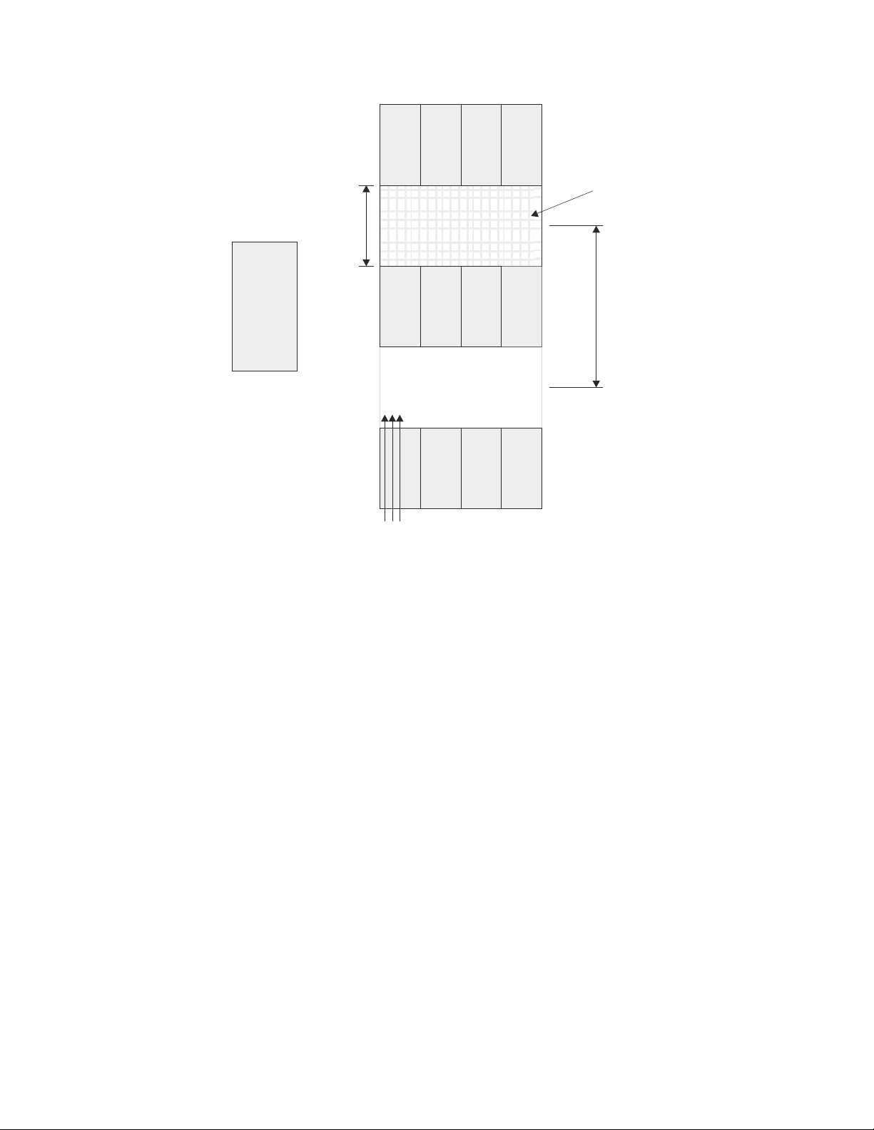
back
T42 racks
1220 mm cold
aisle width
Air
front
Cold aisle
front
T42 racks
back
Perforated tiles
or gratings
and cold aisle
conditioner
Hot aisle
back
T42 racks
front
Airflow
Figure 8. Example of cold aisle/hot aisle rack cabinet configuration
2440 mm between
center lines of hot
f10ug001
16 IBM TotalStorage DS4100 Storage Server: Installation, User’s, and Maintenance Guide
Page 49

Chapter 2. Installing the storage server
This chapter provides the information that you need to install the DS4100 into a
rack cabinet. This chapter also contains information about cabling, setting interface
options, and installing optional cables.
Installation overview
The following steps provide an overview of the installation process you will perform
in this chapter. Each step is detailed in the sections following the overview.
Statement 4:
≥ 18 kg (39.7 lb) ≥ 32 kg (70.5 lb) ≥ 55 kg (121.2 lb)
CAUTION:
Use safe practices when lifting.
Before you begin: The fully configured DS4100 weighs up to 40.8 kg (85.7 lbs). At
least three persons are required to safely lift the DS4100 from the shipping box and
to place it in the rack cabinet. If desired, you can open the sides of the shipping box
and remove the CRUs from the DS4100 before you lift it from the shipping box in
order to reduce the weight of the storage server. See “Removing the CRUs” on
page 25.
1. Review the preparation recommendations. See “Preparing for installation” on
page 18.
2. Prepare the installation site. See “Preparing the site” on page 19.
3. Prepare the rack cabinet. See “Preparing the rack cabinet” on page 19.
4. Unpack the DS4100 and other hardware from the shipping box.
5. Install the support rails in the rack cabinet. See “Installing the support rails” on
page 22.
6. If necessary, remove the CRUs from the DS4100 in order to lighten the
DS4100. See “Removing the CRUs” on page 25.
7. Install the DS4100. See “Installing the DS4100 into a rack cabinet” on page
28. If necessary, replace the CRUs in the DS4100. See “Replacing the
DS4100 CRUs” on page 29.
8. Set the DS4100 interface options. See “Setting the interface options” on page
32.
9. DS4100 base storage server only: If required, cable the DS4100 to other
DS4000 EXP100s. See Chapter 3, “Cabling the storage server,” on page 45.
© Copyright IBM Corp. 2004 17
Page 50
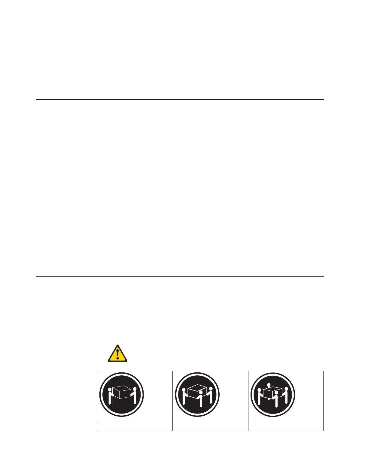
10. Install the DS4000 Storage Manager 9.10 host software. Refer to the IBM
TotalStorage DS4000 Storage Manager 9.10 Installation and Support Guide for
the appropriate operating system for instructions on how to install the DS4000
Storage Manager 9.10 host software.
11. Turn on the DS4100. See “Turning the storage server on and off” on page 65.
12. Use the DS4000 Storage Manager 9.10 host software to verify the
configuration.
Handling static-sensitive devices
Attention: Static electricity can damage electronic devices and your system. To
avoid damage, keep static-sensitive devices in their static-protective packages until
you are ready to install them.
To reduce the possibility of electrostatic discharge (ESD), observe the following
precautions:
v Limit your movement. Movement can cause static electricity to build up around
you.
v Handle the device carefully, holding it by its edges or its frame.
v Do not touch solder joints, pins, or exposed printed circuitry.
v Do not leave the device where others can handle and possibly damage the
device.
v While the device is still in its static-protective package, touch it to an unpainted
metal part of the system unit for at least two seconds. This drains static electricity
from the package and from your body.
v Remove the device from its package and install it directly into your system unit
without setting it down. If it is necessary to set the device down, place it in its
static-protective package. Do not place the device on your system unit cover or
on a metal table. Take additional care when handling devices during cold weather
because heating reduces indoor humidity and increases static electricity.
Preparing for installation
Complete the following steps to prepare the DS4100 for installation into a rack
cabinet.
1. Prepare the site to meet all area, environmental, power, and site requirements.
For more information, see “Storage server operating environment” on page 13.
2. Move the DS4100 to the site.
Statement 4:
≥ 18 kg (39.7 lb) ≥ 32 kg (70.5 lb) ≥ 55 kg (121.2 lb)
18 IBM TotalStorage DS4100 Storage Server: Installation, User’s, and Maintenance Guide
Page 51

CAUTION:
Use safe practices when lifting.
3. Remove the DS4100 from its shipping container and check the contents (see
“Inventory checklist” on page 5). If any items are missing, contact your IBM
reseller before proceeding.
4. Assemble the tools and equipment that you will need for installation. These
might include:
v The power cords that are shipped with the DS4100
v Number 2 Phillips and medium flat-blade screwdrivers
v Antistatic protection (such as a grounding wrist strap)
v Fibre channel and Ethernet interface cables and cable straps
v SFP modules
v The rack-mounting hardware that ships with the DS4100
v The DS4000 Storage Manager Version 9.10 Support CD, which includes the
IBM DS4000 Storage Manager 9.1 software and DS4000 storage server
controller firmware 05.42.xx.xx. You use this software to configure the storage
subsystems. For the latest controller firmware, check the IBM support web
site for DS4000 storage products.
www.ibm.com/servers/storage/disk/
5. Continue with “Preparing the site.”
Preparing the site
This section lists the floor space requirements and weight information for the
DS4100. For information on interface cables and connections, see Chapter 3,
“Cabling the storage server,” on page 45.
Floor space: The floor area at the installation site must provide the following
conditions:
v Enough stability to support the weight of the fully configured DS4100 and
associated systems
v Sufficient space to install the DS4100
Weight:
The DS4100 total weight depends on the number of DS4000 1.5 Gbps
SATA hard disk drives that are installed. A fully configured DS4100 with two fans,
two power supplies, two RAID controllers, and up to 14 SATA hard disk drives
installed weighs 40.8 kg (85.7 lbs).
Continue with “Preparing the rack cabinet.”
Preparing the rack cabinet
Important: Before you install the DS4100 in a rack cabinet, keep in mind the
following considerations:
v Review the documentation that comes with your rack cabinet for safety and
cabling considerations.
v Install the DS4100 in a recommended 22° C (72° F) environment.
v To ensure proper airflow, do not block the air vents; 15 cm (6 in.) of air space is
sufficient.
v To ensure rack stability, load the rack cabinet starting at the bottom.
v If you install multiple components in the rack cabinet, do not overload the power
outlets.
Chapter 2. Installing the storage server 19
Page 52

v Always connect the storage server to a properly grounded outlet.
v Always connect the rack power distribution units (PDUs) to at least two different
power circuits or sources.
Complete
the following steps to prepare the rack cabinet before you install the
DS4100:
1. Move, unpack, and level the rack cabinet at the installation site (if needed).
2. Remove the external rack panels.
3. If necessary, stop all I/O activity to the devices in the rack cabinet.
4. If necessary, turn off all storage expansion unit and rack cabinet power.
Disconnect existing power, network, and other external cables.
5. Install any additional interface cables and power cables.
After you have completed these steps, continue with “Installing the DS4100.”
Installing the DS4100
This section provides instructions on how to install the DS4100 in a rack cabinet.
Rack mounting template
Attention: Duplicate copies of the rack mounting templates are provided in
Appendix B, “Rack mounting template,” on page 121. If you want to tear out the
templates from this document for easier use, use the copies in Appendix B, “Rack
mounting template,” on page 121 rather than the copies provided in this section.
Use the following templates (Figure 9 on page 21 and Figure 10 on page 22) to
identify the proper locations for inserting M6 screws when mounting the support
rails and DS4100 to a rack cabinet. The locations for the M6 screws are highlighted
in the templates.
The DS4100 is 3 U high. Align the template with the rack at a U boundary. U
boundaries are shown as horizontal dashed lines in the rack mounting templates.
Note: The mounting holes that are shown in the following templates are square.
The holes in your rack cabinet might be round, square, or threaded.
20 IBM TotalStorage DS4100 Storage Server: Installation, User’s, and Maintenance Guide
Page 53

3 U
2 U
1 U
Rack Mounting
Bezel
()Front Left
Rail assembly
()Front Left
DS4100
FRONT
Template
Bezel
()Front Right
Rail assembly
()Front Right
3 U
2 U
1 U
0 U
Figure 9. Front rack mounting template
f10ug058
0 U
Chapter 2. Installing the storage server 21
Page 54

3 U
3 U
DS4100
REAR
Rack Mounting
Template
2 U
1 U
0 U
Figure 10. Rear rack mounting template
Installing the support rails
Before installing the DS4100 in a rack cabinet, you must install the rails and
rack-mounting hardware that come with your storage server. The DS4100 requires
an Electronic Industries Association (EIA) 310-D Type A 19-inch rack cabinet. The
distance between EIA rails, from the front to the rear of the rack cabinet, is 60.96
cm (24 in.) minimum and 81.28 cm (32 in.) maximum. This rack cabinet conforms to
the EIA standard. Where you place the support rails in the rack cabinet depends on
where you intend to position the storage server.
Rail assembly
()Rear Left
Rail assembly
()Rear Right
Printed in the U.S.A.
2 U
1 U
®
f10ug059
0 U
Complete the following steps to install the support rails:
Note: Refer to Figure 12 on page 24 while performing these steps.
1. Ensure that the rack cabinet has already been installed.
2. Ensure that a stabilizer has been correctly attached to the bottom front of the
rack cabinet to prevent the rack cabinet from tipping forward while the DS4100
is being installed.
Refer to the installation and service guide, or equivalent, for the rack cabinet
as required.
3. Locate the two support rails and six of the eight M6 screws that are supplied
with the DS4100.
22 IBM TotalStorage DS4100 Storage Server: Installation, User’s, and Maintenance Guide
Page 55

Attention: Both support rails are shipped with three screws and spacers,
called alignment pins, already installed at the front of each rail. They have
been inserted in the front of each support rail as guides to indicate where not
to use M6 screws when you attach the front of the support rail to the rack
cabinet. See Figure 11.
1
Alignment pins with spacers
2
Alignment pin without spacer
3
f10ug057
Figure 11 . Alignment pins with and without spacers
Depending on which type of rack mounting flange is present on your rack
cabinet, you might have to remove some or all of the spacers. For example, if
the rack cabinet in which you are installing the support rails has round holes,
you will need to remove the spacers from the top and bottom alignment pins
so that the rail sits flush with the rack cabinet. See Table 11.
Table 11 . Alignment pin requirements for different rack flange hole types
Rack flange type Pins to remove
Square hole None
Round hole 1 and 3
Threaded hole All
4. The rack-mounted unit is three EIA units high. Decide accordingly where you
are going to install the support rails.
Attention: Use the rack mounting template provided in Figure 9 on page 21
and Figure 10 on page 22 to locate the proper rack mounting holes for
installing the support rails into the rack cabinet.
Note the following considerations before you choose where to install the rails:
v If you are installing the DS4100 into an empty rack, install it into the lowest
available position so that the rack does not become unstable.
v If you are installing more than one DS4100 in the rack, start at the lowest
available position, and work upward.
v If appropriate, allow for possible later installation of other units.
v If necessary, remove the rack power distribution unit before you install the
support rails.
v For procedures and more information, refer to the installation and service
guide, or equivalent, for the rack cabinet.
Chapter 2. Installing the storage server 23
Page 56

5. Starting with the left rail, remove and save the 6/32 in. screw (5). Loosen the
four rail adjustment screws (2).
The support rails are not marked as Left or Right. However, each rail
Note:
can be correctly mounted on only one side of the rack cabinet. The rails
should be mounted with the alignment pins at the front of the rack
cabinet. Figure 12 shows the installation of the left support rail.
6. Hold the front of the rail against the inside of the right rack-mounting flange
and loosely tighten the lower M6 screw (4). See Figure 9 on page 21 for the
location for this screw.
7. Extend the rear of the support rail until it makes contact with the rear rack rail.
8. From the rear of the rack, thread and tighten two M6 screws (1) (see
Figure 10 on page 22 for the location for these screws). From the front of the
rack cabinet, finish tightening the front M6 screw (4).
When you are the finished, the rail should be attached to the cabinet using one
M6 screw in the front (inserted at the second-to-lowest hole) and two M6
screws at the back.
9. Repeat step 5 through step 8 for the right rail.
5
5
6
Rear of Rack
Figure 12. Installing the support rails
10. Tighten the rail adjustment screws 2 on both rails.
11. Continue with “Removing the CRUs” on page 25.
f10ug050
24 IBM TotalStorage DS4100 Storage Server: Installation, User’s, and Maintenance Guide
Page 57

Removing the CRUs
Attention: This section describes how to remove the CRUs in order to minimize
the weight of the DS4100 before you install it in the rack cabinet. However, if you
have three or more people available to lift and install the DS4100 in a rack cabinet,
you might not find it necessary to remove the CRUs before you install the DS4100.
If this is the case, you can skip the CRU removal instructions provided in this
section. Instead, continue with “Installing the DS4100 into a rack cabinet” on page
28, and then skip the CRU replacement instructions provided in “Replacing the
DS4100 CRUs” on page 29.
Use the following procedures to remove the CRUs from the DS4100 before
installation. Use these instructions after you have completed all applicable site, rack
cabinet, and DS4100 preparations (as discussed in “Preparing for installation” on
page 18) and installed the support rails (as discussed in “Installing the support rails”
on page 22). Alternately, if necessary, you can use these instructions to lighten the
DS4100 before removing it from the shipping box. The shipping box opens to
provide access to the storage server CRUs.
The DS4100 comes with a rack-mounting hardware kit for installing it in a rack
cabinet. It is easier to lift the DS4100 and install it in a rack cabinet if you remove
all the CRUs first. You will need an antistatic wrist strap and a cart or level surface
(to hold the CRUs). Observe the precautions listed in “Handling static-sensitive
devices” on page 18. In the following procedure, you will remove the following
CRUs from the storage server before you install it in the rack cabinet:
v RAID controllers
v Power supplies
v Fans
v Hot-swap hard disk drives
do not need to remove the blank trays.
You
Statement 4:
≥ 18 kg (39.7 lb) ≥ 32 kg (70.5 lb) ≥ 55 kg (121.2 lb)
CAUTION:
Use safe practices when lifting.
Attention: The storage server comes with a bezel that is attached to the front of
the unit. The bezel protects the light pipes that are located above the drive trays.
Leave the protective bezel in place until you are instructed to remove it.
Removing a RAID controller
Complete the following steps to remove a RAID controller:
Chapter 2. Installing the storage server 25
Page 58

1. Push down on the latch (centered above the RAID controller). Pull both levers
at the same time out of the locked position.
f10ug033
Figure 13. Removing a RAID controller
2. Grasp the pull-rings; then pull on the levers and remove the RAID controller.
3. Place the RAID controller on a level surface.
4. For the DS4100 base storage server, repeat step 1 through step 3 for the
second RAID controller.
In the DS4100 single-controller storage server, you do not need to
Note:
remove the controller blank.
Removing a power supply
Complete the following steps to remove a power supply:
1. Grasp the pull-ring on the power supply lever and squeeze the latch to release
it.
2. Pull the lever open 90° and remove the power supply, as shown in Figure 14 on
page 27.
26 IBM TotalStorage DS4100 Storage Server: Installation, User’s, and Maintenance Guide
Page 59
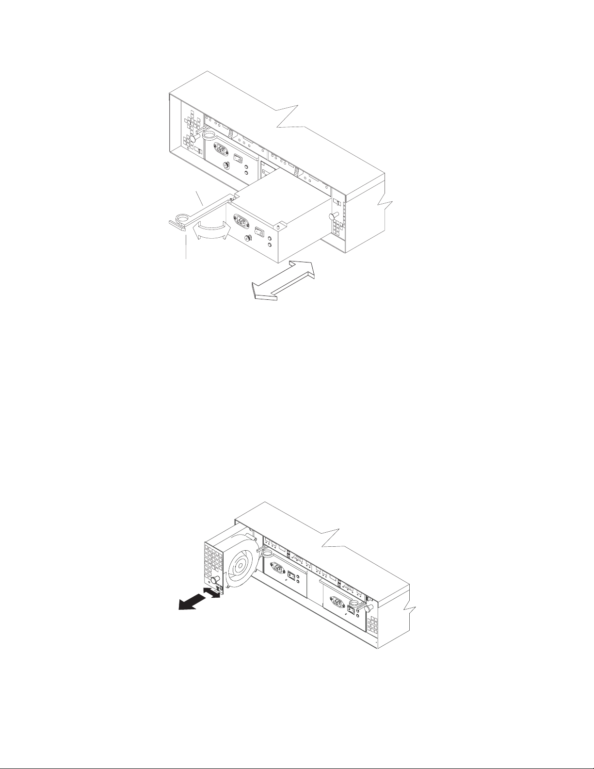
Lever
Pull ring
f10ug054
Figure 14. Removing a power supply
3. Place the power supply on a level surface.
4. For the DS4100 base storage server, repeat step 1 through step 3 for the
second power supply.
In the DS4100 single-controller storage server, you do not need to
Note:
remove the power supply blank.
Removing a fan
Complete the following steps to remove a fan:
1. Unlock the latch by moving the latch in the same direction as the latch direction
arrow shown on the back of the fan.
2. Grasp the handle and pull the fan unit out of the bay, as shown in Figure 15.
Figure 15. Removing a fan
3. Place the fan unit on a level surface.
4. Repeat step 1 through step 3 for the second fan unit.
Chapter 2. Installing the storage server 27
f10ug038
Page 60

Removing a hard disk drive
Complete the following steps to remove a hot-swap hard disk drive:
Note: The hard disk drive comes installed in a drive tray. Do not attempt to detach
the hard disk drive from the drive tray.
1. Use Table 19 on page 119 to record the location and identify your DS4000
SATA hard disk drives. You must record this information to be able to replace
the hard disk drives in their original order before they were removed.
2. Release the latch on the drive CRU by pinching together the blue line on the
tray latch and the finger hole on the tray handle.
3. Pull the tray handle out so that it is in the open position to release the drive
CRU. Pull the drive out of the bay, as shown in Figure 16.
Tray handle
Figure 16. Removing a drive CRU
4. Place the removed drive CRUs horizontally on a level surface, with the printed
circuit boards facing down.
Attention: Do not stack drive CRUs on top of one another. Protect the drive
CRUs from vibrations or sudden shocks.
5. Repeat step 1 through step 4 for additional drive CRUs.
Continue with “Installing the DS4100 into a rack cabinet.”
Installing the DS4100 into a rack cabinet
Complete the following steps to install the DS4100 in a rack cabinet.
1. Place the DS4100 in the rack cabinet.
If you have removed the CRUs from the DS4100, you should be able to
Note:
lift the unit into the cabinet with the help of one other person. If you have
not removed the CRUs before the installation, you should have at least
two other people available to help you lift the unit into the rack cabinet.
a. Move the DS4100 to the front of the rack-mount cabinet.
b. With help from another person, place the back of the storage server on the
support rails. Slide the unit into the rack cabinet, as shown in Figure 17 on
page 29.
f10ug055
28 IBM TotalStorage DS4100 Storage Server: Installation, User’s, and Maintenance Guide
Page 61

Front of Rack
f10ug051
Figure 17. Installing the DS4100
2. The bezel is secured to the front of the DS4100 either by plastic wingnuts or by
adhesive tape. Remove and discard the wingnuts or the adhesive tape. The
bezel should remain attached to the DS4100 chassis.
Attention: The bottom cross member of the bezel has a tab that must fit
beneath the DS4100 chassis and snap into place. The top cross member of the
bezel has a recess that must be mated with a metal tab on the bottom of the
DS4100 chassis.
3. Secure the DS4100 to the rack cabinet:
a. Align the front mounting holes on each side of the storage server with the
mounting holes on the front of the support rails.
b. Install the bezel.
c. Insert an M6 screw into the mounting hole on both sides of the front of the
unit (see Figure 9 on page 21). Gently tighten the screws to secure the
bezel and the front of the DS4100 to both of the front cabinet rails.
Attention: Do not overtighten. If you overtighten these screws, you could
break the bezel.
d. From the back of the rack cabinet, insert the two 6/32 in. screws (5 in
Figure 12 on page 24), one on each side, in the holes located on the tab on
each side of the unit. Tighten the screws.
Continue with one of the following actions:
4.
v If you did remove the DS4100 CRUs before installation (as described in
“Removing the CRUs” on page 25), continue with “Replacing the DS4100
CRUs.”
v If you did not find it necessary to remove the DS4100 CRUs before
installation, continue with “Setting the interface options” on page 32.
Replacing the DS4100 CRUs
Use the following procedures to replace the CRUs in the DS4100 after installation.
Chapter 2. Installing the storage server 29
Page 62

Replacing a RAID controller
Complete the following steps to replace the RAID controller that you removed
before the installation:
f10ug033
Figure 18. Replacing a RAID controller
1. Slide the RAID controller all the way into the empty slot.
2. Close both levers until the latch locks into place.
Attention: Make sure that the levers lock into place in the storage server
chassis.
3. For the DS4100 base storage server, repeat step 1 and step 2 to replace the
second RAID controller.
Replacing a power supply
Complete the following steps to replace the power supplies that you removed
before the installation:
1. Slide one power supply into the storage server. Be sure to replace the power
supplies so that the lever on each power supply opens toward the interior of the
storage server, as shown in Figure 19 on page 31.
Attention: Be sure that the lever is pulled straight out as you slide the power
supply into the storage server, as shown in Figure 19 on page 31.
30 IBM TotalStorage DS4100 Storage Server: Installation, User’s, and Maintenance Guide
Page 63

Lever
Pull ring
f10ug054
Figure 19. Replacing a power supply
2. Close the lever until the pull-ring latch locks in place. Make sure that the lever
locks into place in the storage server chassis. Then gently push the front of the
power supply to ensure that it is fully seated.
3. For the DS4100 base storage server, repeat step 1 and step 2 to replace the
second power supply.
Replacing a fan
Complete the following steps to replace the fan units that you removed before the
installation:
1. Place the fan in front of the fan bay.
2. Ensure that you move the fan latch in the same direction as the arrow before
you slide the fan all the way into the bay. If the fan does not go into the bay,
rotate it 180° (see Figure 20).
Figure 20. Replacing a fan
f10ug038
Chapter 2. Installing the storage server 31
Page 64
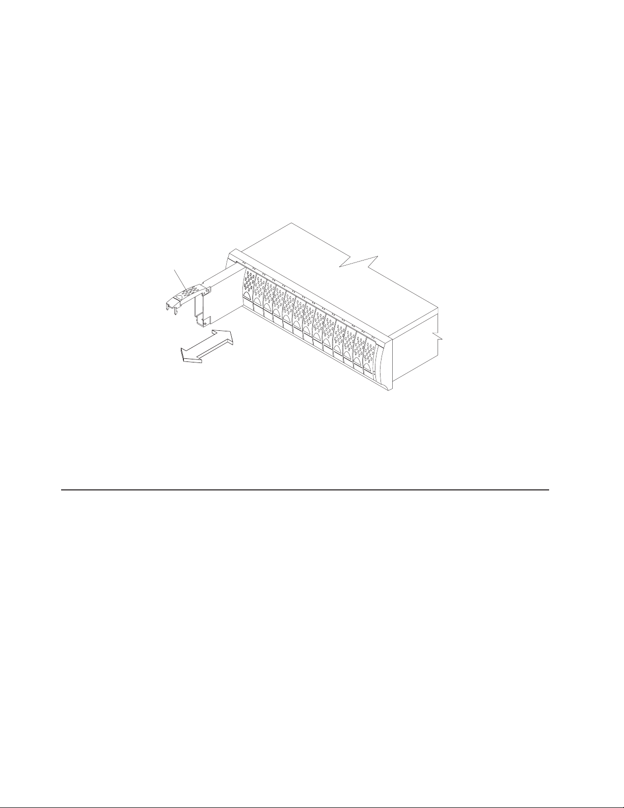
3. If the latch does not automatically lock when you have successfully inserted the
fan unit into the bay, pull back slightly on the fan and then push it in again until
the latch snaps into place.
4. Repeat step 1 through step 3 to replace the second fan.
Replacing a hard disk drive
Complete the following steps to replace the hot-swap hard disk drives that you
removed before the installation.
Note: Use Table 19 on page 119 to verify the proper replacement locations of your
DS4000 1.5 Gbps SATA hard disk drives.
Tray handle
Figure 21. Removing a drive CRU
1. Lift up on the handle and gently push the drive CRU into the empty bay until the
hinge of the tray handle latches beneath the storage server bezel.
2. Push the tray handle down until the latch clicks into place.
3. Repeat step 1 and step 2 to replace additional drives.
Setting the interface options
The DS4100 has two server ID switches that identify the DS4100 on a fibre-channel
loop and that assign physical addresses to the drives. The server ID switches are
located on the back of the storage server, as shown in Figure 22 on page 33.
f10ug055
32 IBM TotalStorage DS4100 Storage Server: Installation, User’s, and Maintenance Guide
Page 65

1 Gb/s 2 Gb/s
X10
X1
Tray Number
Conflict
1 Gb/s 2 Gb/s
Conflict
X10
X1
Tray Number
2 Gb/s Enclosure Speed
LED (Green)
Server ID switch
Figure 22. Enclosure ID switches
Fibre channel loop and ID settings
When you install a hard disk drive in the expansion unit, the drive tray plugs into a
printed circuit board called the midplane. The midplane sets the fibre channel loop
ID automatically, based on the enclosure ID switch setting and the physical location
(bay) of the hard disk drive.
Server ID (enclosure ID) settings
The DS4100 comes with a server ID switch (also referred to as an enclosure ID
switch) that is used to identify the DS4100 on a fibre channel loop. The server ID
switch is located on the back of the unit, as shown in Figure 22.
Use the small buttons above and below each server ID digit to change the server
ID setting. Press the button located above the digit to lower the digit by one. Press
the button located below the digit to raise the digit by one.
ID Conflict LED (Amber)
f10ug046
Note: Some storage servers ship with a panel installed over the server ID switch to
prevent the server ID from being changed accidentally. If your storage server
has a protective panel over the server ID switch, use a pencil or a small
screwdriver to change the server ID.
Each storage expansion unit in a DS4000 storage subsystem drive loop must have
a unique enclosure ID. DS4000 controllers use a combination of the enclosure ID
and the number of the physical slot that a fibre channel hard drive occupies to
create a unique fibre channel loop address or arbitrated loop physical address
(AL_PA) for each drive in a fibre channel drive loop. The enclosure ID consists of
two digits, a tens digit (x10) and ones digit (x1).
Note: The DS4100 is shipped with 00 as the default server ID setting. If you
connect the storage server to a DS4000 EXP100, you must set the DS4000
EXP100 enclosure ID setting to a value other than 00. Each server unit
should have a unique ID if it is going to be connected to other drive
expansion units through the drive loop ports. The Server ID setting is only
Chapter 2. Installing the storage server 33
Page 66

valid for the drive loop. The amber Conflict LED (located on the right-side of
the switch) will be lit if another unit in the drive loop has the same ID setting
as the server ID.
Attention: When connecting the DS4100 to DS4000 EXP100 storage expansion
units, DO NOT use the tens digit (x10) setting. Use only the ones digit (x1) setting
to set unique server IDs or enclosure IDs.
Give each drive expansion enclosure in a redundant drive loop a unique ones digit
(x1) ID. This setting will enforce hard AL_PAs (unchangeable between fibre channel
Loop Initializations [LIPs]) for the drives and facilitate drive loop problem
troubleshooting in the event of an error. If the ones digits are not unique, two or
more devices will have the same hard AL_PA. In such a case, the controller will use
soft AL_PAs for the devices that have identical hard AL_PAs.
The problem with soft addressing is that addresses may change between LIPs. This
possibility increases the difficulty of troubleshooting drive loop problems, since one
cannot easily ascertain whether the same device with a different address or
different device may be causing a problem.
Storage server speed settings
The default switch setting is 2 Gbps. This is the only speed setting allowed for the
DS4100.
Attention: Do not remove the metal plate that covers the storage server speed
setting. Do not adjust the storage server speed setting.
Configuring the storage subsystem
You must configure the storage subsystem configuration after you install the storage
server in a rack cabinet. Use the information in the following sections to configure
your storage subsystem configuration.
Storage subsystem management methods
Before you configure the storage subsystem, determine which method of storage
subsystem management you want to use. You can manage the storage subsystems
in either of two ways: host-agent (in-band) management or direct (out-of-band)
management.
Important: If the operating system of the host server that the storage subsystem
logical drive(s) is mapped to is not Microsoft
to make a direct (out-of-band) management connection to the storage
subsystem to set the correct host type first. Then, the server will be
able to recognize the storage subsystem correctly for host-agent
(in-band) management.
Host-agent (in-band) management method
This method requires host-agent software that you install on the host server. The
host-agent software allows the DS4000 Storage Manager client program to manage
the DS4000 storage subsystem using the same fibre channel connections between
the host server and the storage subsystem. You must install at least one
management station and a software agent host. The management station can be
the host or a workstation on the Ethernet network. A management station will have
the client software installed. Figure 23 on page 35 shows the host-agent (in-band)
management method.
®
Windows NT®, you have
34 IBM TotalStorage DS4100 Storage Server: Installation, User’s, and Maintenance Guide
Page 67
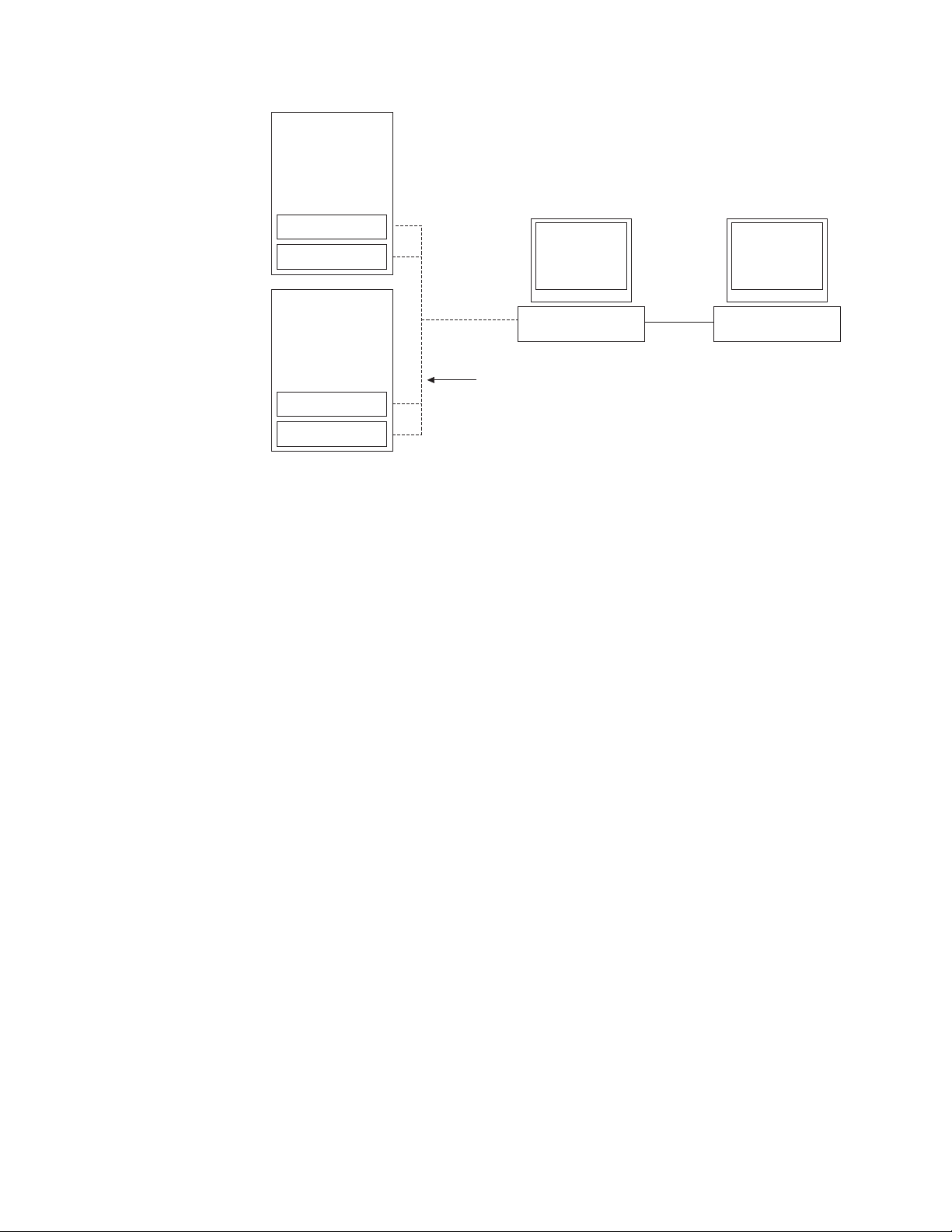
Controller
Controller
Host-agent
software
Fibre Channel
I/O path
Controller
Controller
Ethernet
Note: The client software is
Client software
Management station
(one or more)
installed on one or more
management systems,
or on the host computer.
Figure 23. Host-agent (in-band) managed storage subsystems
Direct (out-of-band) management method
This method uses Ethernet connections from a management station to each
controller. You must install at least one management station. The management
station can be the host or a workstation on the Ethernet network. A management
station will have the client software installed. Attach Ethernet cables to each
management station (one pair per storage server). Yo u will connect the cables to
each storage server controller later when you install the storage server. Figure 24
on page 36 shows the direct (out-of-band) management method.
Note: Do not connect the DS4100 storage server Ethernet ports to a public
network or public subnet. It is strongly recommended that you create a
private network between the DS4100 storage server and the management
station.
f10ug004
Chapter 2. Installing the storage server 35
Page 68

Controller
Controller
Host computer
Fibre Channel
I/O path
Controller
Controller
Storage subsystems
Note: The client software is
installed on one or more
management systems,
or on the host computer.
Ethernet
Figure 24. Direct (out-of-band) managed storage subsystems
Fibre channel connections
The storage server fibre channel connection consists of up to four host
fibre-channel loops and a redundant drive fibre-channel loop. The host fibre-channel
loops provide the fibre path for host attachment. They can consist of fibre-channel
cables, SFPs, host bus adapters, fibre-channel switches, and RAID controllers. The
redundant drive fibre-channel loop provides the fibre path to the hard disk drives
(HDDs). The redundant drive fibre-channel loop consists of fibre channel HDDs and
optional storage expansion units, fibre-channel cables, and SFPs.
Exception: The DS4100 single-controller storage server does not support drive
loops or expansion units.
The DS4100 base storage server supports redundant disk-drive-loop configurations.
Each RAID controller has three SFP ports. These SFP ports are labeled Host 1,
Host 2, and Expansion. You can build a redundant drive loop by connecting one or
more expansion units to the redundant RAID controllers. Then, use dual fiber-optic
cables to connect one expansion unit to another in a daisy-chain. For more
information about adding expansion units, see “Connecting expansion units (base
storage server only)” on page 57.
f10ug008
Management station
Fibre channel loop configurations
You must determine how the host systems will connect to the storage server. You
can connect up to two host systems directly to the storage server, or you can
36 IBM TotalStorage DS4100 Storage Server: Installation, User’s, and Maintenance Guide
Page 69

connect more than two hosts to the fibre channel storage server through switches.
The illustrations in the following sections show common host system configurations.
Note: The default configuration is one partition. Four-partition, eight-partition, and
sixteen-partition configuration upgrades are available as upgrade options.
You must perform partition upgrades one increment at a time, which means
you cannot upgrade directly from a four-partition configuration to a
sixteen-partition configuration; in this case, you would have to upgrade from
a four-partition configuration to an eight-partition configuration, and then from
the eight-partition configuration to a sixteen-partition configuration. Contact
your IBM reseller or marketing representative for more information.
Redundant host and drive loops
This section provides examples of DS4100 host fibre channel configurations.
DS4100 base storage server configurations: This section provides the following
examples of DS4100 base storage server host fibre channel configurations.
v Redundant host and drive fibre channel loop configurations, as shown in
Figure 25 on page 38
v Single SAN fabric configuration, as shown in Figure 26 on page 39
v Dual SAN fabric configuration, with an additional DS4100 and a DS4000 EXP100
attached, as shown in Figure 27 on page 39
v Two clusters, as shown in Figure 28 on page 40
These configurations have host and drive path failover protection and are
Note:
recommended for high availability.
Chapter 2. Installing the storage server 37
Page 70
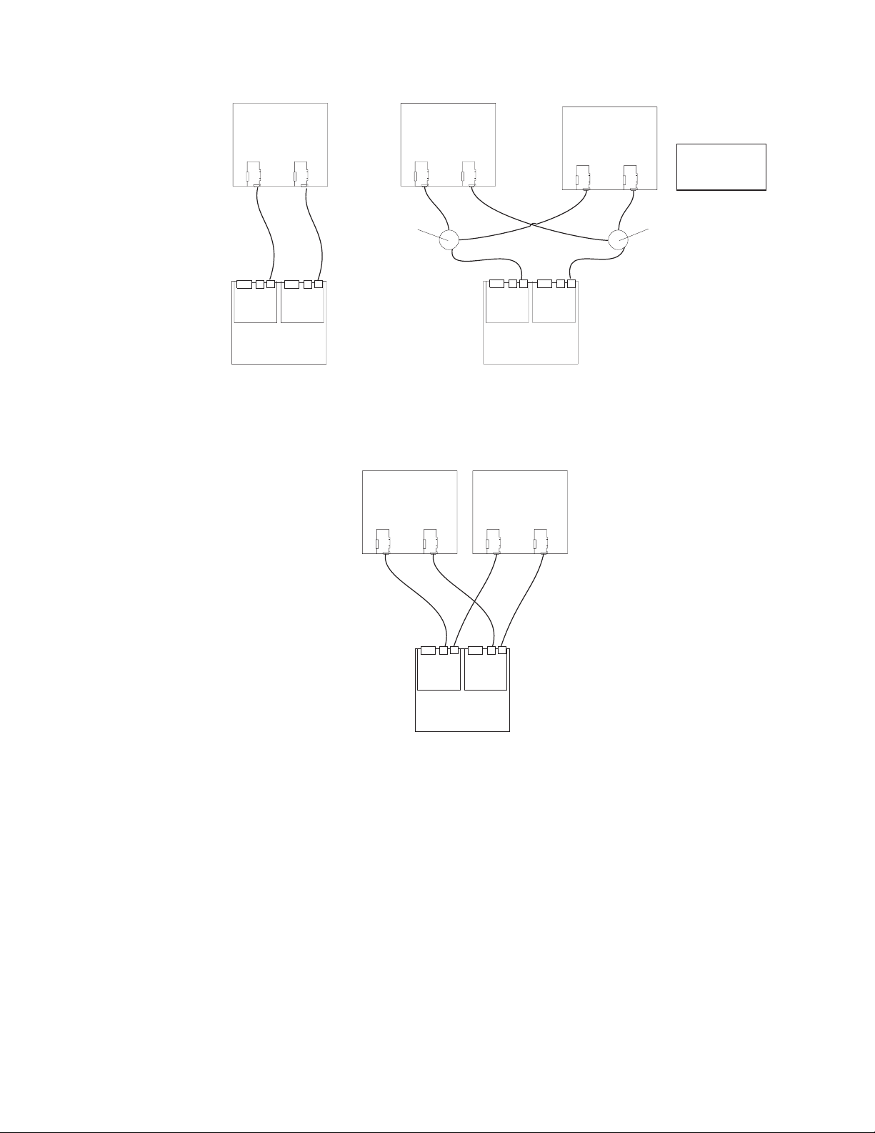
Host system
with two host
adapters
Host system
with two host
adapters
Host system
with two host
adapters
Note: Node level
redundancy with
cluster software.
DS4100
Switch
Host system
with two host
adapters
DS4100
Host system
with two host
adapters
Switch
DS4100
Figure 25. Examples of redundant host and drive fibre channel loop configurations (base
storage server)
In Figure 26 on page 39, the fibre channel switches are connected together via the
inter-switch link (ISL) to form a single SAN fabric.
38 IBM TotalStorage DS4100 Storage Server: Installation, User’s, and Maintenance Guide
f10ug028
Page 71

Host system
with two host
adapters
Host system
with two host
adapters
Switch
Switch
Interswitch link
DS4100
f10ug043
Figure 26. Example of a single SAN fabric configuration (base storage server)
In Figure 27, the fibre channel switches are not connected together. Each switch
forms its own SAN fabric.
Host system
with two host
adapters
Host system
with two host
adapters
Switch
DS4100
Switch
DS4100
DS4000 EXP100
(Expansion unit)
Figure 27. Example of a dual SAN fabric configuration (base storage server)
Chapter 2. Installing the storage server 39
f10ug042
Page 72
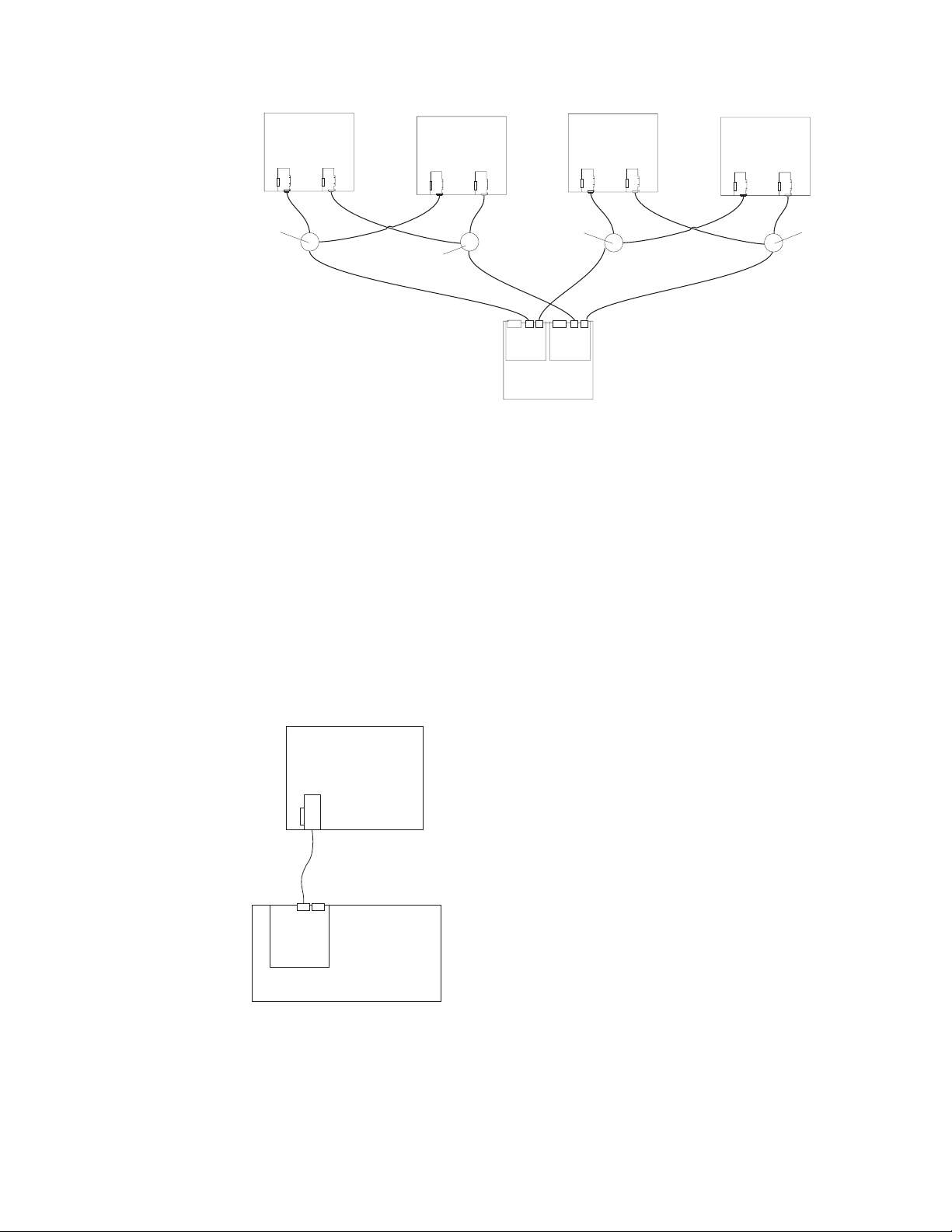
Host system
with two host
adapters
Host system
with two host
adapters
Host system
with two host
adapters
Host system
with two host
adapters
DS4100
Switch
Switch
Switch
Switch
Figure 28. Example of a two-cluster configuration (base storage server)
DS4100 single-controller storage server configurations: This section provides
the following examples of DS4100 single-controller storage server host fibre
channel configurations.
v Single server configuration with one adapter, as shown in Figure 29
v Single server configuration with two adapters, as shown in Figure 30 on page 41
v Dual server configuration with one adapter on each server, as shown in Figure 31
on page 41
v Dual-server, single-SAN fabric configuration with one adapter on each server, as
shown in Figure 32 on page 42
v Dual-server, single-SAN fabric configuration with two adapters on each server, as
shown in Figure 33 on page 42
f10ug044
Host
Server
DS4100 Single
Controller
f11ug001
Figure 29. Example of a single server configuration with one adapter (single-controller
storage server)
40 IBM TotalStorage DS4100 Storage Server: Installation, User’s, and Maintenance Guide
Page 73

Host
Server
DS4100 Single
Controller
f11ug002
Figure 30. Example of a single server configuration with two adapters (single-controller
storage server)
Host
Server
Host
Server
DS4100 Single
Controller
f11ug003
Figure 31. Example of a dual server configuration with one adapter on each server
(single-controller storage server)
Chapter 2. Installing the storage server 41
Page 74

Host
Server
Host
Server
FC
Switch
DS4100 Single
Controller
f11ug004
Figure 32. Example of a dual-server, single-SAN fabric configuration with one adapter on
each server (single-controller storage server)
Host
Server
FC
Switch
D4100 Single
Controller
Host
Server
FC
Switch
DS4100 Single
Controller
f11ug005
Figure 33. Example of a dual-server, single-SAN fabric configuration with two adapters on
each server (single-controller storage server)
Installing the storage subsystem configuration
Using the information gathered in the previous sections, install the host systems
and host adapters.
Notes:
1. See the documentation provided with your host adapters for installation
requirements and procedures.
42 IBM TotalStorage DS4100 Storage Server: Installation, User’s, and Maintenance Guide
Page 75

2. Use the correct host adapter driver. For the latest supported host adapters and
drivers, go to the following Web site:
www.ibm.com/servers/storage/disk/
fiber-optic interface cables to each host adapter. Yo u will connect the other
Attach
end of the cables to the controller later in the installation process. For more
information about handling fiber-optic cables, see “Handling fiber-optic cables” on
page 45.
Note: Do not install the DS4000 Storage Manager client at this time, if it is not
already installed. Install the storage server completely before you install the
software because you cannot test the software installation until the hardware
is connected.
Chapter 2. Installing the storage server 43
Page 76

44 IBM TotalStorage DS4100 Storage Server: Installation, User’s, and Maintenance Guide
Page 77

Chapter 3. Cabling the storage server
This chapter provides fibre channel and power cabling information for the storage
server.
After you attach the storage server power cables, use the instructions that are
provided in “Turning the storage server on and off” on page 65 for the initial startup
of the storage server.
Working with SFPs and fiber-optic cables
Each RAID controller has two host ports and one expansion port. You use a
small-form factor pluggable transceiver (SFP) to connect each host port and
expansion port to hosts and expansion units. The SFP is inserted into the port, and
then a fiber-optic cable is inserted into the SFP. The other end of the fiber-optic
cable connects to an external device. SFPs are laser products.
Statement 3
CAUTION:
When laser products (such as CD-ROMs, DVD drives, fiber optic devices, or
transmitters) are installed, note the following:
v Do not remove the covers. Removing the covers of the laser product could result in
exposure to hazardous laser radiation. There are no serviceable parts inside the
device.
v Use of controls or adjustments or performance of procedures other than those
specified herein might result in hazardous radiation exposure.
Danger
Some laser products contain an embedded Class 3A or Class 3B laser diode. Note the
following.
Laser radiation when open. Do not stare into the beam, do not view directly with optical
instruments, and avoid direct exposure to the beam.
Handling fiber-optic cables
Before you use fiber-optic cables, read the following precautions.
Attention: To avoid damage to the fiber-optic cables, follow these guidelines:
v Do not route the cable along a folding cable-management arm.
v When attaching to a device on slide rails, leave enough slack in the cable so that
it does not bend to a radius of less than 38 mm (1.5 in.) when extended or
become pinched when retracted.
v Route the cable away from places where it can be snagged by other devices in
the rack cabinet.
© Copyright IBM Corp. 2004 45
Page 78

v Do not overtighten the cable straps or bend the cables to a radius of less than 38
mm (1.5 in.).
v Do not put excess weight on the cable at the connection point. Be sure that the
cable is well supported.
Installing SFP modules
The DS4100 host ports require SFP modules. SFP modules are used to convert
electrical signals to optical signals that are required for fibre channel transmission to
and from RAID controllers. The DS4100 supports two types of SFP modules: one
with a plastic latch and one with a wire latch. After you install the SFP modules, you
use fiber-optic cables to connect the DS4100 to other fibre channel devices.
Before you install SFP modules and fiber-optic cables, read the following
information:
v Do not mix long-wave SFPs and short-wave SFPs on a single storage server.
Use either long-wave SFPs or short-wave SFPs. You can use the DS4000
Storage Manager client to view the storage subsystem profile in order to verify
that you are not mixing long-wave and short-wave SFPs.
v The SFP module housing has an integral guide key designed to prevent you from
inserting the SFP module improperly.
v Use minimal pressure when you insert the SFP module into a port. Forcing the
SFP module into a port could cause damage to the SFP module or the port.
v Yo u can insert or remove the SFP module while the port is powered on.
v The operational loop performance is not affected when you install or remove an
SFP module.
v Yo u must insert the SFP module into a port before you connect the fiber-optic
cable.
v Yo u must remove the fiber-optic cable from the SFP module before you remove
the SFP module from the port. See “Removing SFP modules” on page 48 for
more information.
install an SFP module, complete the following steps.
To
Statement 3:
CAUTION:
When laser products (such as CD-ROMs, DVD drives, fiber-optic devices, or
transmitters) are installed, note the following:
v Do not remove the covers. Removing the covers of the laser product could
result in exposure to hazardous laser radiation. There are no serviceable
parts inside the device.
v Use of controls or adjustments or performance of procedures other than
those specified herein might result in hazardous radiation exposure.
46 IBM TotalStorage DS4100 Storage Server: Installation, User’s, and Maintenance Guide
Page 79

DANGER
laser products contain an embedded Class 3A or Class 3B laser
Some
diode. Note the following.
Laser radiation when open. Do not stare into the beam, do not view directly
with optical instruments, and avoid direct exposure to the beam.
Attention: When you handle static-sensitive devices, take precautions to avoid
damage from static electricity. For details about handling static-sensitive devices,
see “Handling static-sensitive devices” on page 18.
1. Remove the SFP module from its static-protective package.
2. Remove the protective cap from the SFP module, as shown in Figure 34. Save
the protective cap for future use.
Plastic tab
Protective cap
SFP module
F10ug014
Figure 34. Small Form-Factor Pluggable (SFP) module
3. Remove the protective cap from the host port. Save the protective cap for future
use.
4. Insert the SFP module into the host port until it clicks into place. See Figure 35.
RAID controller
SFP module
f10ug041
Fiber-optic
cable
Figure 35. Installing an SFP module into the host port
5. Connect a fibre channel cable.
Chapter 3. Cabling the storage server 47
Page 80

Removing SFP modules
To remove the SFP module from the host port, perform the following steps.
Attention: To avoid damage to the cable or to the SFP module, make sure you
unplug the LC-LC fibre channel cable before you remove the SFP module.
1. Remove the LC-LC fibre channel cable from the SFP module. For more
information, see “Handling fiber-optic cables” on page 45.
2. Unlock the SFP module latch:
v For SFP modules that contain plastic tabs, unlock the SFP module latch by
pulling the plastic tab outward 10°, as shown in Figure 36.
Protective cap
o
10
Plastic tab
SFP module
F10ug009
Figure 36. Unlocking the SFP module latch - plastic variety
v For SFP modules that contain wire tabs, unlock the SFP module latch by
pulling the wire latch outward 90°, as shown in Figure 37.
Wire tab
Protective cap
o
90
SFP module
F10ug010
Figure 37. Unlocking the SFP module latch - wire variety
3. With the SFP latch in the unlocked position, extract the SFP module.
v For SFP modules that contain plastic tabs, slide the SFP module out of the
port.
v For SFP modules that contain wire tabs, grasp the wire latch and pull the
SFP module out of the minihub port.
Replace the protective cap on the SFP module.
4.
5. Place the SFP module into a static-protective package.
6. Replace the protective cap on the port.
Installing fiber-optic cables
To connect the fiber-optic cables, perform the following steps.
48 IBM TotalStorage DS4100 Storage Server: Installation, User’s, and Maintenance Guide
Page 81
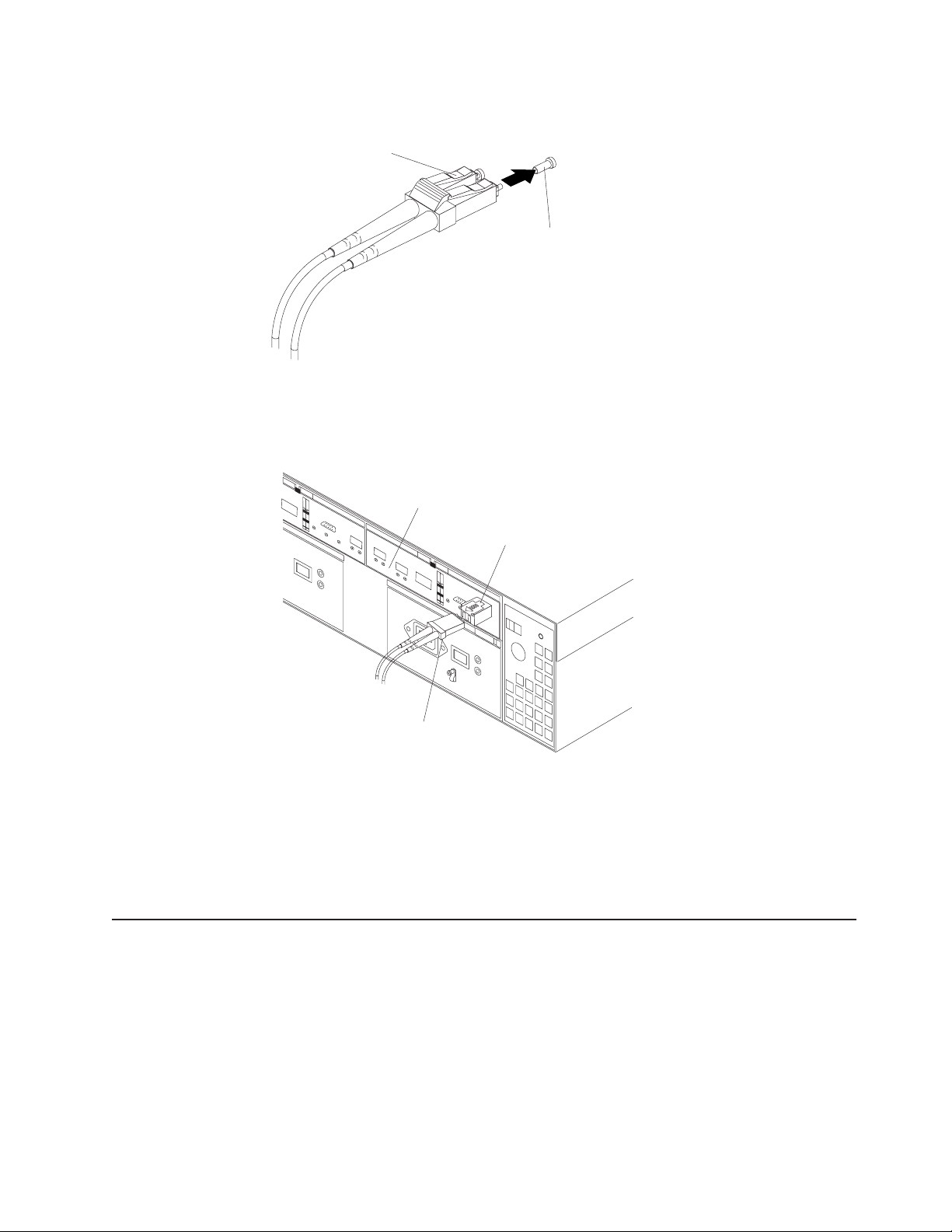
1. Remove the protective cap from the fiber-optic cable. See Figure 38.
Fiber-optic
cable
Protective cap
F10ug011
Figure 38. Removing caps from fiber-optic cables
2. Connect the fiber-optic cable to the installed SFP, as shown in Figure 39.
RAID controller
Fiber-optic
cable
Figure 39. Connecting cables to the installed SFP
3. Check the LEDs on the RAID controller. When the RAID controller is operating
properly, the amber Fault LED is off. For information about the status of the
RAID controller LEDs, see Table 13 on page 73.
4. To remove the fiber-optic cables, gently pull the fiber-optic cable from the SFP;
then replace the protective caps.
Using LC-LC fibre-channel cables
The LC-LC fibre-channel cable is a fiber-optic cable that you use to connect into
one of the following devices:
v An SFP module installed in an IBM DS4100
v An SFP module installed in an IBM DS4000 EXP100 expansion unit
SFP module
f10ug041
Figure 40 on page 50 for an illustration of the LC-LC fibre-channel cable.
See
Chapter 3. Cabling the storage server 49
Page 82

For more information about cabling these devices, see the documentation that
comes with the LC-LC fibre-channel cable.
fg0ug019
Figure 40. LC-LC fibre-channel cable
Note: If you are connecting the DS4100 to a 1 Gbps device (such as a 1 Gbps
fibre channel switch), you must also use an LC-SC fibre-channel cable
adapter. For more information about using an LC-SC fibre-channel cable
adapter, see “Using LC-SC fibre-channel cable adapters” on page 52.
Connecting an LC-LC cable to an SFP module
Complete the following steps to connect an LC-LC fibre-channel cable to an SFP
module:
Statement 3:
CAUTION:
When laser products (such as CD-ROMs, DVD drives, fiber optic devices, or
transmitters) are installed, note the following:
v Do not remove the covers. Removing the covers of the laser product could
result in exposure to hazardous laser radiation. There are no serviceable
parts inside the device.
v Use of controls or adjustments or performance of procedures other than
those specified herein might result in hazardous radiation exposure.
DANGER
Some laser products contain an embedded Class 3A or Class 3B laser
diode. Note the following.
Laser radiation when open. Do not stare into the beam, do not view directly
with optical instruments, and avoid direct exposure to the beam.
1. Read the information in “Handling fiber-optic cables” on page 45.
50 IBM TotalStorage DS4100 Storage Server: Installation, User’s, and Maintenance Guide
Page 83

2. If necessary, remove the protective cap from the SFP module, as shown in
Figure 34 on page 47. Save the protective cap for future use.
3. Remove the two protective caps from one end of the LC-LC cable, as shown in
Figure 41. Save the protective caps for future use.
Fiber-optic
cable
Protective cap
F10ug011
Figure 41. Removing fiber-optic cable protective caps
4. Carefully insert this end of the LC-LC cable into an SFP module that is installed
in the DS4100. The cable connector is keyed to ensure it is inserted into the
SFP module correctly. Holding the connector, push in the cable until it clicks into
place, as shown in Figure 42.
42. Inserting an LC-LC fibre-channel cable into an SFP module
Figure
5. Remove the two protective caps from the other end of the LC-LC cable. Save
the protective caps for future use.
6. Connect this end of the LC-LC cable to the SFP module that is installed in a
DS4000 EXP100.
Removing an LC-LC fibre-channel cable
Complete the following steps to remove an LC-LC fibre-channel cable:
Attention: To avoid damaging the LC-LC cable or SFP module, make sure that
you press and hold the lever to release the latches before you remove the cable
from the SFP module. Ensure that the levers are in the released position when
removing the cable. When removing the cable from the SFP module, make sure
that you do not grasp the SFP module plastic tab.
F10ug016
Chapter 3. Cabling the storage server 51
Page 84

1. On the end of the LC-LC cable that connects into the SFP module or host bus
adapter, press down and hold the lever to release the latches, as shown in
Figure 43.
Lever
Latches
f10ug018
Figure 43. LC-LC fibre-channel cable lever and latches
2. Carefully pull on the connector to remove the cable from the SFP module, as
shown in Figure 44.
f10ug017
Figure 44. Removing the LC-LC fibre-channel cable
3. Replace the protective caps on the cable ends.
4. Replace the protective cap on the SFP module.
Using LC-SC fibre-channel cable adapters
The LC-SC fibre-channel cable adapter is a fiber-optic cable that is used to connect
an LC connector into one of the following devices that require SC connectors:
v 1-Gbps fibre channel switch
v Fibre channel host bus adapter
more information about connecting to these devices, see the documentation
For
that comes with the LC-SC fibre-channel cable adapter.
52 IBM TotalStorage DS4100 Storage Server: Installation, User’s, and Maintenance Guide
Page 85

LC connector
SC connector
Figure 45. LC-SC fibre-channel cable adapter
The following sections provide the procedures for properly connecting and removing
an LC-SC fibre-channel cable.
Connecting an LC-SC cable adapter to a device
Complete the following steps to connect an LC-SC fibre-channel cable adapter to a
device:
Statement 3:
f10ug012
CAUTION:
When laser products (such as CD-ROMs, DVD drives, fiber optic devices, or
transmitters) are installed, note the following:
v Do not remove the covers. Removing the covers of the laser product could
result in exposure to hazardous laser radiation. There are no serviceable
parts inside the device.
v Use of controls or adjustments or performance of procedures other than
those specified herein might result in hazardous radiation exposure.
DANGER
Some laser products contain an embedded Class 3A or Class 3B laser
diode. Note the following.
Laser radiation when open. Do not stare into the beam, do not view directly
with optical instruments, and avoid direct exposure to the beam.
1. Read the information in “Handling fiber-optic cables” on page 45.
2. Connect one end of an LC-LC cable to an SFP module in the DS4100. For
instructions, see “Using LC-LC fibre-channel cables” on page 49.
Chapter 3. Cabling the storage server 53
Page 86

3. Remove the two protective caps from the LC connector end of the LC-SC cable
adapter as shown in Figure 46. Save the protective caps for future use.
f10ug013
Figure 46. Removing the LC-SC cable adapter protective caps
4. Carefully insert the other end of the LC-LC cable into the LC connector end of
the LC-SC cable adapter as shown in Figure 47. Push in the connector until it
clicks into place.
f10ug020
Figure 47. Connecting an LC-LC cable into the LC-SC cable adapter
5. If you are connecting the DS4100 to a 1-Gbps fibre channel switch or fibre
channel host bus adapter, connect the SC connector end of the LC-SC cable
adapter to a Gigabit Interface Converter (GBIC) that is installed in the 1-Gbps
fibre channel switch or fibre channel host bus adapter. For more information
about connecting to these devices, see the documentation that comes with the
device.
Removing an LC-LC cable from an LC-SC cable adapter
Complete the following steps to remove an LC-LC cable from an LC-SC cable
adapter:
Attention: To avoid damaging the LC-LC cable, make sure you press and hold
the lever to release the latches before you remove the cable from an LC-SC cable
adapter. Ensure that both levers are in the released position when removing the
cable. When removing the cable from the SFP module, make sure you do not grasp
the SFP module plastic tab.
54 IBM TotalStorage DS4100 Storage Server: Installation, User’s, and Maintenance Guide
Page 87

1. On the end of the cable that connects into the LC connector end of the LC-SC
cable adapter, press down and hold the lever to release the latches. Figure 48
shows the location of the lever and latches.
Lever
Latches
f10ug018
Figure 48. LC-LC fibre-channel cable lever and latches
2. Carefully pull on the connector to remove it. Make sure you grasp the connector
and not the cable when removing the LC-LC cable from the LC-SC cable
adapter as shown in Figure 49.
f10ug015
49. Removing the LC-LC fibre-channel cable from an LC-SC fibre-channel cable
Figure
adapter
3. Replace the protective caps on the cable ends.
Connecting hosts to the RAID controllers
Complete the procedure that is appropriate to your DS4100 storage server model:
v “Connecting hosts to a DS4100 base storage server” on page 55
v “Connecting hosts to a DS4100 single-controller storage server” on page 56
Connecting hosts to a DS4100 base storage server
To connect a host adapter to the DS4100 base storage server RAID controllers,
perform the following steps:
1. Install an SFP in a host port on the RAID controller.
2. Connect the host-system cables to the RAID controller or to switches. Figure 50
on page 56 shows the location on the RAID controllers where the host-system
cables connect.
Chapter 3. Cabling the storage server 55
Page 88

Controller A
Host A: Host Adapter 1
(or from managed hub
or switch)
Controller B
f10ug029
Host A: Host Adapter 2
(or from managed hub
or switch)
Figure 50. Location of host cables (base storage server)
For examples of redundant, partially-redundant, and non-redundant host and drive
loop configurations, see “Fibre channel loop configurations” on page 36.
Connecting hosts to a DS4100 single-controller storage server
To connect a host adapter to the DS4100 single-controller storage server RAID
controllers, perform the following steps:
1. Install an SFP in a host port on the RAID controller.
2. Connect the host-system cables to the RAID controller or to switches. Figure 51
shows the location on the RAID controllers where the host-system cables
connect.
Ethernet Serial port
Host port 2
Host port 1
AC power
connector
AC power
switch
Server ID
Figure 51. Location of host cables (single-controller storage server)
Connecting secondary interface cables
Use the Ethernet interface ports on the back of the storage server to connect the
controllers for direct management of the storage subsystems (see “Direct
(out-of-band) management method” on page 35).
f11ug006
switch
This section is applicable to (direct) out-of-band management configurations only. If
your configuration uses host-agent (in-band) management, skip this section.
56 IBM TotalStorage DS4100 Storage Server: Installation, User’s, and Maintenance Guide
Page 89
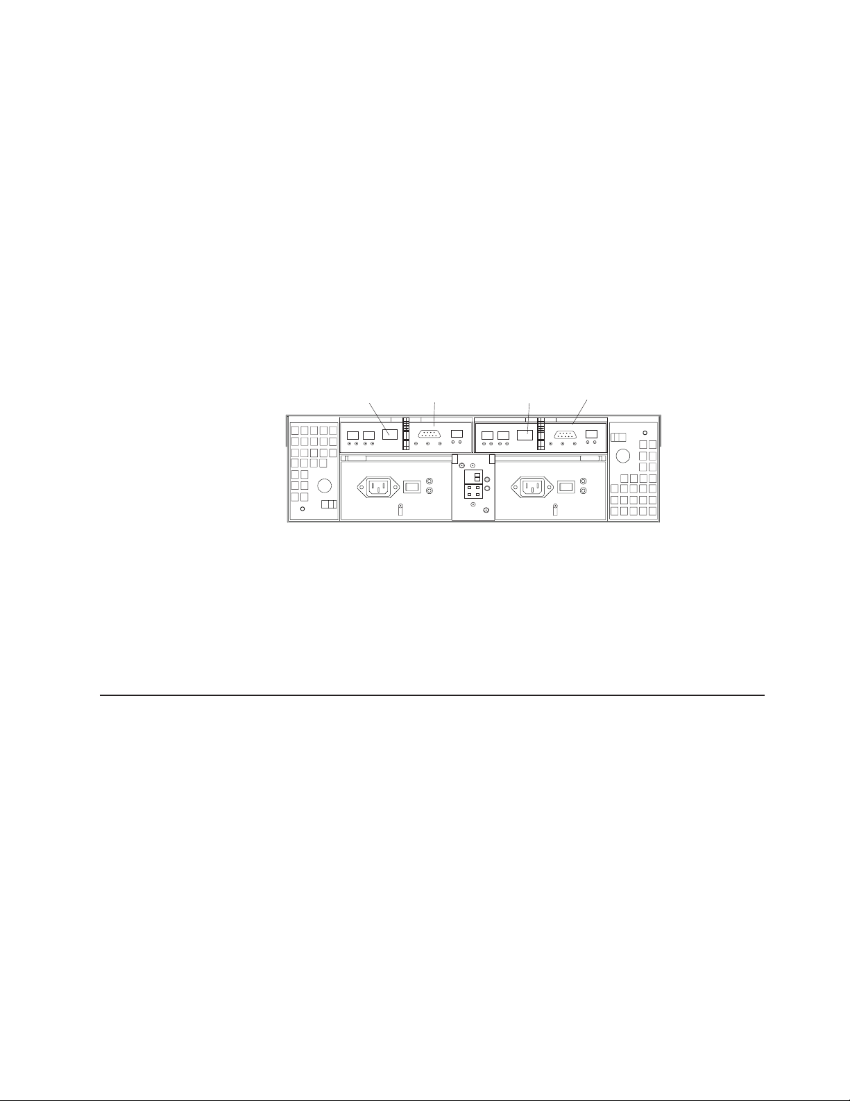
Important:
1. The serial interface ports are intended to be used by service technicians to
perform diagnostic operations on the storage server. Incorrect use of the serial
port can result in loss of data access and, in some cases, in loss of data.
2. Do not connect the DS4100 in a public LAN or public subnet. Use a local
private network for the DS4100 storage server and the management station
Ethernet ports.
3. To ensure proper EMI shielding, always use quality shielded serial cables.
Connecting secondary interface cables to a DS4100 base storage server
Connect a pair of Ethernet cables from the storage-management station to the
Ethernet ports for Controller A (located on the left) and Controller B (located on the
right) on the back of the storage server. Figure 52 shows the location of the ports.
Controller A
Ethernet port
Controller A
Serial port
Controller B
Ethernet port
Controller B
Serial port
f10ug030
Figure 52. Ethernet and serial port locations
Connecting secondary interface cables to a DS4100 single-controller storage server
Connect an Ethernet cable from the storage-management station to the Ethernet
port of the controller.
Connecting expansion units (base storage server only)
Attention: The minimum DS4000 EXP100 ESM firmware level (9554 or later) is
required before attaching a DS4000 EXP100 to the DS4100 base storage server.
Refer to the section “Replacing a failed hot-swap ESM” in the IBM TotalStorage
DS4000 EXP100 Storage Expansion Unit Installation, User’s, and Maintenance
Guide for details on how to identify ESM firmware levels.
You cannot connect expansion units to the DS4100 single-controller storage server.
If you are using the DS4100 single-controller storage server, skip this section.
Please contact your IBM support representative for information about the availability
of such support in the future.
Chapter 3. Cabling the storage server 57
Page 90

Attention: In the initial installation of the DS4100, you can add only new
expansion units to the DS4100 storage server. This means that there must be no
existing configuration information on the expansion unit that you want to install. If
the expansion unit that you want to install currently contains logical drives or
configured hot spares, and you want them to be part of the DS4100 storage server,
refer to the IBM TotalStorage DS4000 Hard Drive and Storage Expansion Enclosure
Installation and Migration Guide. Improper drive migration might cause loss of
configuration and other storage server problems. Contact your IBM support
representative for additional information.
To connect a single additional expansion unit to the storage server, perform the
following steps:
The following procedures are for ″cold-case″ procedures (the DS4100 is
Note:
powered down when expansion units are connected, as in the case of a new
installation). For ″hot-case″ procedures (the DS4100 is powered on when
expansion units are connected), see “Adding a DS4000 EXP100 to an
existing DS4100 configuration (base storage server only)” on page 109. Yo u
can also refer to the IBM TotalStorage DS4000 Hard Drive and Storage
Expansion Enclosure Installation and Migration Guide.
1. Follow the instructions in your expansion unit installation manual to set up and
mount the new expansion unit.
2. Use the following procedure and Figure 53 on page 59 to connect a single
expansion unit to the storage server:
a. Ensure that the enclosure ID switch on the new expansion unit is set to a
value different than the value set for the DS4100 and any other expansion
units in the loop. Also ensure that the link speeds of the expansion units are
set to 2 Gbps. See “Setting the interface options” on page 32.
When connecting the DS4100 to DS4000 EXP100 storage expansion
Note:
units, do not use the tens digit (x10) setting. Use only the ones digit
(x1) setting to set unique server IDs or enclosure IDs. For more
information, see “Server ID (enclosure ID) settings” on page 33.
b. Use a fiber-optic cable to connect to the FC-Expansion Units port on the left
RAID controller in the storage server to the In port on the left ESM board of
the expansion unit.
c. Use a second fiber-optic cable to connect the FC-Expansion Units port on
the right RAID controller in the storage server to the Out port on the right
ESM board of the expansion unit.
58 IBM TotalStorage DS4100 Storage Server: Installation, User’s, and Maintenance Guide
Page 91
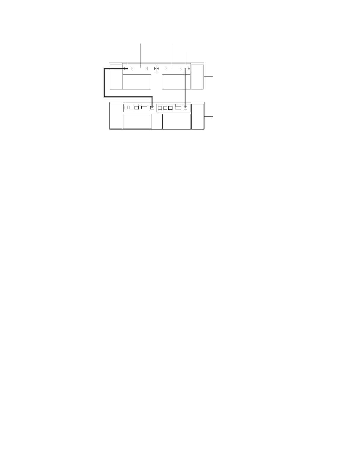
Left ESM board Right ESM board
In port
Out port
New expansion unit
Storage server with
two RAID controllers
f10ug031
Figure 53. Adding an expansion unit
3. Remove the blank filler trays and insert drive trays. Connect power to the drive
expansion unit first and then connect power to the DS4100. After the storage
server is powered on, the storage server locates the new drives.
4. Use the DS4000 Storage Manager client to check the status of the new drives,
correct any errors found, and configure the new drives.
For more detailed information about how to cable the storage server and expansion
units, see the DS4100 Fibre Channel Cabling Instructions that come with the
storage server.
DS4000 EXP100 loop redundancy (DS4100 base storage server only)
The DS4000 EXP100 provides redundant loop support when the second ESM is
configured, and when both loops (called A and B) are connected to a DS4100
storage server model that supports redundant loops. (The DS4100 base storage
server supports redundant loops; the DS4100 single-controller storage server does
not support redundant loops.) If a cable or SFP module fails on drive loop A, drive
loop B provides redundancy, which is an alternate path to your disk drives.
Figure 54 on page 60 shows a redundant loop that you might create with a DS4100
and three DS4000 EXP100s. The numbers provided in Figure 54 on page 60 show
the order in which cables should be attached.
Chapter 3. Cabling the storage server 59
Page 92

Loop A Fibre Channel
interface cable
Left ESM board Right ESM board
Input
Output
3
1
5
Output
Last expansion unit
4
Second expansion unit
6
2
Loop B Fibre Channel
interface cable
First expansion unit
f10ug048
DS4100 storage server
with two RAID controllers
Figure 54. DS4000 EXP100 redundant loop configuration
To create the redundant loop shown in Figure 54, you would perform the following
steps:
1. Make two fibre-channel connections from the First expansion unit to the Second
expansion unit (connections 1 and 2).
2. Make two fibre-channel connections from the Second expansion unit to the Last
expansion unit (connections 3 and 4). Currently, you can connect up to three
DS4000 EXP100s together in a redundant drive loop. Contact your IBM support
representative for information about the availability of future support for
connecting more than three DS4000 EXP100 units.
3. Make a fibre-channel connection from the storage server drive port to the OUT
port in the left ESM of the First expansion unit in the redundant drive loop
(connection 5).
4. Make a fibre-channel connection from the storage server drive port to the IN
port in the right ESM of the Last expansion unit in the redundant drive loop
(connection 6).
IBM S ATA disk drives are dual-ported, providing individual access from two
fibre-channel loops to the same disk drive. When configuring the ESMs, configure
the second ESM the same way that you configured the first ESM. Refer to the
DS4100 Fibre Channel Cabling Instructions for more information about dual-loop
support and implementation.
Each ESM on the DS4000 EXP100 has an SFP module input port and an SFP
module output port. As you cable DS4000 EXP100s together, connecting input ports
to output ports can improve diagnostic capability. Refer to the DS4100 Storage
Server Fibre Channel Cabling Instructions for cabling connections between input
and output ports.
60 IBM TotalStorage DS4100 Storage Server: Installation, User’s, and Maintenance Guide
Page 93

Power cabling
The DS4100 base storage server uses two standard power cords, and the
single-controller storage server uses only one. You can connect the power cords to
a primary power unit inside the rack cabinet, such as a properly grounded ac
distribution unit, or to an external source, such as a properly grounded electrical
outlet.
The DS4100 storage server does not ship with power cords. Refer to Appendix C,
“Power cords,” on page 125 for the list of IBM-approved power cords for your
region. Depending on your model, the DS4100 storage server does ship with one or
two line jumper cords for connecting the DS4100 power supply or power supplies to
an IBM-approved rack power distribution unit.
If you have not already done so, attach the power cords by using Figure 55 for the
location of the component parts.
Lever
f10ug027
AC power
connector
Strain-relief
clamp
-
AC power
switch
Figure 55. Power cord locations
Perform the following to cable the power cords:
1. Connect the power cord to the power supply.
2. Remove the nut that holds the power cable strain-relief clamp, and then remove
the strain-relief clamp.
3. Wrap the strain-relief clamp around the power cord approximately 20 cm (8 in.)
from the power supply connection end. Leave some slack between the clamp
and the power-supply end of the power cord.
4. Replace the power cable strain-relief clamp, and tighten it securely with the nut.
5. Plug the power cord into a properly grounded electrical outlet.
Note: To maintain power redundancy, plug the storage server’s right and left
power supplies into two independent external power circuits through ac
distribution units inside a rack cabinet or directly into external
receptacles. Similarly, the right and left power supplies of the DS4000
storage expansion units attached to the DS4100 should be plugged into
the same two independent external power circuits as the DS4100.
It is recommended that you determine the maximum surge current
possible when all devices in the power circuit are started at the same
time. Based on the total number of devices on a power circuit, find the
maximum (worst-case) specification value in order to prevent the circuit
from tripping. When both power supplies are connected and the storage
server is powered on, each power supply unit will handle approximately
Chapter 3. Cabling the storage server 61
Page 94

one-half of the current load. If there is only one power supply unit, it will
handle all of the current load. To ensure maximum protection against
power loss due to power supply unit failure or a power circuit tripping,
both power supply units must be connected and powered on. See
Table 10 on page 15 for the DS4100 AC power requirements.
See Figure 56 for an example of redundant power cabling.
Exception: The DS4100 single-controller storage server has only one
power supply, so it does not support power redundancy.
Rack power cable connector
Drive expansion unit
Rack power cable
power supplies
Controller power supplies
AC distribution units
AC distribution unit
power cord
Figure 56. Redundant AC power connections to controllers and drive expansion units
For details about power requirements, see “DS4100 specifications” on
page 14.
6. Go to “Turning the storage server on and off” on page 65 for the initial startup of
the storage server.
Attention: Before you power on the storage server, any storage expansion
units should be completely connected to the storage server.
f10ug060
Installing the DS4000 Storage Manager client
Refer to the IBM TotalStorage DS4000 Storage Manager 9.10 Installation and
Support Guide for the appropriate operating system for instructions on how to install
the Storage Manager software. Use that document and the online help to configure
the logical drives, partitions, and so on for the RAID controllers. Use your operating
62 IBM TotalStorage DS4100 Storage Server: Installation, User’s, and Maintenance Guide
Page 95

system documentation to make the new logical drives accessible to the operating
system. Do not proceed with the configuration set-up you have completed the
DS4000 Storage Manager installation.
Assemble any additional items in preparation for software installation. These items
might include:
v HBA drivers
v Controller firmware version 05.42.xx.xx
v IP addresses for RAID controllers (for in-band management only)
v Additional documentation for switches and HBAs, if needed
v DS4000 Storage Manager Version 9.10 Support CD, which includes the IBM
DS4000 Storage Manager 9.1 software and DS4000 storage server controller
firmware 05.42.xx.xx. You use this software to configure the storage subsystems.
For the latest controller firmware, check the IBM support web site for DS4000
storage products.
www.ibm.com/servers/storage/disk/
any planned system shutdown or after any system additions, removals, or
Before
modifications (including logical drive creations, storage partitioning definitions,
hardware changes, and so on), save the storage subsystem profile as explained in
the DS4000 Storage Manager guide for your operating system. Save the profile in a
location other than the logical drives created for the DS4100 storage server.
Important: Controller firmware version 05.42.xx.xx is required for the DS4100.
However, this version of the controller firmware should be used only for
the DS4100. Do not use controller firmware version 05.42.xx.xx for any
DS4000 storage servers other than the DS4100. This version of the
controller firmware does not support intermix of fibre-channel drive
expansion enclosures. Please contact your IBM support representative
for information about the availability of such support in the future.
Always refer to the readme that is included with the DS4100 storage
server firmware package (whether the firmware is accessed by the Web
or CD) for any special requirements or restrictions that apply to that
particular firmware version.
Note: Make sure that you install the DS4000 Storage Manager event monitoring
service to enable continuous monitoring of the status of the storage server.
For more information about the importance of this information, see
“Monitoring status through software” on page 70.
Chapter 3. Cabling the storage server 63
Page 96

64 IBM TotalStorage DS4100 Storage Server: Installation, User’s, and Maintenance Guide
Page 97

Chapter 4. Operating the storage server
To ensure optimal operation of your system, always follow these best practices
guidelines:
v Back up the data on your storage drives periodically.
v DS4100 base storage server only: To maintain power redundancy, plug the
storage server’s right and the left power supplies into two independent external
power circuits through ac distribution units inside a rack cabinet or directly into
external receptacles. Similarly, the right and left power supplies of the DS4000
storage expansion units attached to the DS4100 should be plugged into the
same two independent external power circuits as the DS4100. This ensures that
the DS4100 and all its attached storage expansion units will have power if only
one power circuit is available. In addition, having all the right or all the left power
supplies plug into the same power circuit will enable the components in the
storage subsystem to power on simultaneously during an unattended restoration
of power. See Figure 56 on page 62 for an example of redundant power
connections.
v Before any planned system shutdown or after any system additions, removals, or
modifications (including logical drive creations, storage partitioning definitions,
hardware changes, and so on), save the storage subsystem profile as explained
in the DS4000 Storage Manager guide for your operating system. Save the
profile in a location other than the logical drives created for the DS4100 storage
server.
v Ensure that your system is in an optimal state before you shut it down. Never
turn the power off if any fault light is lit; be sure to resolve any error conditions
before you shut down the system.
v During any maintenance or attended power-up procedure, carefully follow the
power-up sequence listed in “Turning on the storage server” on page 66. You
should check that each component of the subsystem is powered-on in the proper
order during this entire power-up procedure to ensure that the controller will
optimally access all of your storage subsystems.
v The storage subsystem supports simultaneous power-up to the system
components; however, you should always follow the power-up sequence listed in
“Turning on the storage server” on page 66 during any attended power-up
procedure.
v A storage system in an optimal state should recover automatically from an
unexpected shutdown and unattended simultaneous restoration of power to
system components. After power is restored, call IBM support if any of the
following conditions occur:
– The storage subsystem logical drives and arrays are not displayed in the
DS4000 Storage Manager graphical user interface (GUI).
– The storage subsystem logical drives and arrays do not come online.
– The storage subsystem logical drives and arrays seem to be degraded.
Turning the storage server on and off
This section contains instructions for turning the storage server on and off under
normal and emergency situations.
If you are turning on the storage server after an emergency shutdown or power
outage, see “Restoring power after an emergency shutdown” on page 69.
© Copyright IBM Corp. 2004 65
Page 98

Turning on the storage server
Important: DS4100 base storage server only: You must turn on the storage
expansion units and verify that the storage expansion unit fibre channel
connections are optimal by checking the indicator lights before you turn
on the DS4100. The controllers might not recognize the correct
configuration if the hard disk drives are powered up after the DS4100.
For instructions on how to power up the storage expansion units, refer
to the storage expansion unit documentation.
Always wait at least 30 seconds between the time you turn off a power
Note:
switch and the time you turn on the power again.
Perform the following steps to turn on the power for the initial startup of the storage
server:
1. Verify that:
a. All communication and power cables are plugged into the back of the
storage server and a properly grounded ac electrical outlet.
b. All hard disk drives are locked securely in place. For more information, see
“Installing hot-swap hard disk drives” on page 80.
Note: At least one drive must be present before you start the DS4100.
Attention: If you are restarting the system after a normal shutdown, wait at
least 10 seconds before you turn on the power by using the power-on sequence
in step 2.
2. Check the system documentation for the hardware devices that you intend to
power up, and then determine the proper startup sequence. Use the following
power-on sequence, where applicable:
a. Turn on the power to the supporting devices (for example, Ethernet switches
and management stations) before the storage server.
Attention: If you will be directly managing the storage array, you must set
up the Dynamic Host Configuration Protocol (DHCP) or BOOT-P server
before you turn on the power. Setting up the server allows the controllers to
obtain the corresponding IP address when you turn on the power to the
array module. For more information, see the software installation guide for
your operating system.
b. Yo u must turn on the expansion units before the storage server. The
controllers might not recognize the correct configuration if the drives are
powered up after the storage server. For instructions on how to power up
the expansion units, see the expansion-unit documentation.
c. Turn on the power to the storage server; then restart or turn on the power to
the host.
Note: Depending on your operating system, you might not have to restart
the host. For more information, see the software installation guide for
your operating system.
Turn on the power to each device, based on the power-on sequence in step 2.
3.
To turn on power to the storage server, turn on the power-supply switches on
the back of the storage server. Yo u must turn on both power-supply switches to
take advantage of the redundant power supplies.
4. Use the DS4000 Storage Manager client and the Fault LEDs to check the
overall status of the storage server and its components. All LEDs should be
66 IBM TotalStorage DS4100 Storage Server: Installation, User’s, and Maintenance Guide
Page 99

green on the front of the storage server. If they are not, use the DS4000
Storage Manager client to diagnose the problem (see “Monitoring status through
software” on page 70).
Note: The green drive active LED and amber drive fault LED below the drive
CRUs might flash intermittently as the drives spin-up. Wait until the
storage server is finished powering up before checking the LEDs on the
front of the storage server. For more information, see “Checking the
LEDs” on page 71.
Turning off the storage server
Attention: Except in an emergency, never turn off the power if any storage server
Fault LEDs are on. Correct the fault before you turn off the power. Use the DS4000
Storage Manager client and the Fault LEDs to check the overall status of the
storage server and its components. All LEDs should be green on the front of the
storage server. If they are not, use the DS4000 Storage Manager client to diagnose
the problem (see “Monitoring status through software” on page 70). This ensures
that the storage server will power up correctly later. For more information, see
Chapter 6, “Hardware maintenance,” on page 111 .
The storage server is designed to run continuously, 24 hours a day. After you turn
on the storage server, do not turn it off. Turn off the power only when:
v Instructions in a hardware or software procedure require you to turn off the
power.
v A service technician tells you to turn off the power.
v A power outage or emergency situation occurs (see “Performing an emergency
shutdown” on page 69).
Statement 5:
CAUTION:
The power control button on the device and the power supply do not turn off
the electrical current supplied to the device. The device also might have more
than one power cord. To remove all electrical current from the device, ensure
that all power cords are disconnected from the power source.
2
1
Perform the following steps to turn off the power:
1. Before proceeding, use the DS4000 Storage Manager client to determine the
status of the system components and special instructions. The operating system
software might require you to perform other procedures before you turn off the
power.
2. Use the DS4000 Storage Manager client to check the status of the storage
server. Correct problems that are reported before you turn off the power.
Chapter 4. Operating the storage server 67
Page 100

3. Stop all I/O activity to the storage server and attached expansion units. Make
sure that:
v All of the green Drive active LEDs on the front of the storage server (and on
all attached expansion units) are not flashing.
v The green Cache active LEDs on the back of the storage server are off.
Attention: To turn off all power to the storage server, you must turn off both
power-supply switches and disconnect both power cords. Use the procedure in
step 6 for the proper shutdown sequence.
4. Before the storage server is powered off, use the operating system software to
either disconnect the storage server logical drives from the host or to flush the
logical drive data cache in the host server memory.
5. If applicable, use the operating system software to disconnect the storage
server logical drives from the host before the storage server is powered off.
6. Turn off the power to each device based on the following shutdown sequence:
a. Turn off power to the host before the storage server. If the host must stay
powered on to support an existing network, see the operating system
documentation for information about disconnecting the storage server logical
drives from the host before the storage server is powered off.
b. Turn off power to the storage server before you turn off power to the
expansion units. Turn off both power supply switches on the back of the
storage server.
c. Turn off power to other supporting devices (for example, management
stations, fibre-channel switches, or Ethernet switches).
Note: You do not need to perform this step if you are servicing only the
storage server.
7. After you perform the necessary maintenance procedures, turn on the power
using the procedure in “Turning on the storage server” on page 66.
Restoring power after an unexpected shutdown
The storage server might shut down unexpectedly under any of the following
conditions:
Attention: There might be data loss in each of the following cases:
v The internal temperature of the storage server exceeds the maximum operating
temperature (an over-temperature condition).
If both fan CRUs fail or are unable to maintain an internal temperature below 70°
C (158° F), one or both of the power supplies in the storage server will shut
down. If both power supplies shut down, the unit is inoperable.
The DS4000 Storage Manager client warns you if the temperature of the unit is
rising before it has risen sufficiently to shut down the power supplies. The first
warning comes when the storage server internal temperature exceeds 45° C
(113° F). The storage server shuts down if the temperature rises to 70° C (158°
F).
v There is a general power failure or a loss of power to the unit.
v Yo u are forced to shut down the storage server without performing the normal
shutdown procedures (listed in “Turning off the storage server” on page 67)
because of an emergency situation.
68 IBM TotalStorage DS4100 Storage Server: Installation, User’s, and Maintenance Guide
 Loading...