

Page 1

8239 Token-Ring Stackable Hub ÉÂÔ
Setup and User’s Guide
GA27-4209-00
Page 2

Page 3

8239 Token-Ring Stackable Hub ÉÂÔ
Setup and User’s Guide
GA27-4209-00
Page 4

Note
Before using this document, read the general information under “Notices” on page ix.
First Edition (June 1998)
This edition applies to the 8239 Token-Ring Stackable Hub and to all subsequent releases and modifications until otherwise indicated
in new editions or technical newsletters.
Order publications through your IBM representative or the IBM branch office serving your locality. Publications are not stocked at the
address below.
IBM welcomes your comments. A form for readers' comments is provided at the back of this publication. If the form has been
removed, you may address your comments to:
International Business Machines Corporation
Design and Information Development
Department CGF
P.O. Box 12195
Research Triangle Park, NC 27709-9990
U.S.A.
When you send information to IBM, you grant IBM a nonexclusive right to use or distribute the information in any way it believes
appropriate without incurring any obligation to you.
Copyright International Business Machines Corporation 1998. All rights reserved.
Note to U.S. Government Users — Documentation related to restricted rights — Use, duplication or disclosure is subject to
restrictions set forth in GSA ADP Schedule Contract with IBM Corp.
Page 5

Contents
Notices . . . . . . . . . . . . . . . . . . . . . . . . . . . . . . . . . . . . . . . . . . ix
Safety Information . . . . . . . . . . . . . . . . . . . . . . . . . . . . . . . . . . . . ix
Safety Information Booklet .............................. ix
Power Disconnection . . . . . . . . . . . . . . . . . . . . . . . . . . . . . . . . . . xiii
Electronic Emission Notices .............................. xiv
Federal Communications Commission (FCC) Statement ........... xiv
Industry Canada Class A Emission Compliance Statement .......... xv
Avis de conformité aux normes d'Industrie Canada .............. xv
European Community (CE) Mark of Conformity Statement .......... xv
Japanese Voluntary Control Council for Interference (VCCI) Statement ... xvi
Taiwanese Class A Warning Statement ..................... xvi
Battery Disposal . . . . . . . . . . . . . . . . . . . . . . . . . . . . . . . . . . . . xvi
Trademarks . . . . . . . . . . . . . . . . . . . . . . . . . . . . . . . . . . . . . . . xvi
Preface . . . . . . . . . . . . . . . . . . . . . . . . . . . . . . . . . . . . . . . . . xvii
How This Manual Is Organized ............................ xvii
Related Publications . . . . . . . . . . . . . . . . . . . . . . . . . . . . . . . . . . xvii
Visit our Web Site .................................. xviii
Chapter 1. Introduction and Planning ...................... 1-1
Models . . . . . . . . . . . . . . . . . . . . . . . . . . . . . . . . . . . . . . . . . . 1-1
Features . . . . . . . . . . . . . . . . . . . . . . . . . . . . . . . . . . . . . . . . . 1-2
Configuration . . . . . . . . . . . . . . . . . . . . . . . . . . . . . . . . . . . . . . 1-3
Concentrator Functions . . . . . . . . . . . . . . . . . . . . . . . . . . . . . . . . 1-3
Device and Network Management .......................... 1-3
Cable Types and Distances .............................. 1-4
Ports . . . . . . . . . . . . . . . . . . . . . . . . . . . . . . . . . . . . . . . . . 1-4
Stack Unit Cabling ................................. 1-4
RI/RO Module . . . . . . . . . . . . . . . . . . . . . . . . . . . . . . . . . . . . 1-5
Physical Specifications . . . . . . . . . . . . . . . . . . . . . . . . . . . . . . . . . 1-5
Dimensions . . . . . . . . . . . . . . . . . . . . . . . . . . . . . . . . . . . . . . 1-5
Placement . . . . . . . . . . . . . . . . . . . . . . . . . . . . . . . . . . . . . . 1-6
Weight . . . . . . . . . . . . . . . . . . . . . . . . . . . . . . . . . . . . . . . . 1-6
Service Clearances . . . . . . . . . . . . . . . . . . . . . . . . . . . . . . . . . 1-6
Environmental Requirements . . . . . . . . . . . . . . . . . . . . . . . . . . . 1-6
Power Requirements . . . . . . . . . . . . . . . . . . . . . . . . . . . . . . . . 1-7
Chapter 2. Installing the 8239 Hardware ..................... 2-1
Preparing for Setup .................................. 2-1
Verifying the Shipment ................................. 2-1
Installing Features . . . . . . . . . . . . . . . . . . . . . . . . . . . . . . . . . . . 2-2
Placing the 8239 .................................... 2-2
Surface-Mounting the 8239 ............................ 2-2
Rack-Mounting the 8239 .............................. 2-2
Connecting the Cables ................................. 2-4
Connecting Stations to the 8239 ......................... 2-4
Cabling a Stack ................................... 2-5
Connecting an ASCII Terminal or Modem to the EIA-232 Port ........ 2-5
Powering On the 8239 ................................. 2-6
Copyright IBM Corp. 1998 iii
Page 6

Chapter 3. Installing Features . . . . . . . . . . . . . . . . . . . . . . . . . . . 3-1
16-Port Expansion Feature .............................. 3-1
Removing a 16-Port Expansion Feature ..................... 3-1
Installing a 16-Port Expansion Feature ...................... 3-1
RI/RO Module . . . . . . . . . . . . . . . . . . . . . . . . . . . . . . . . . . . . . . 3-2
Removing a RI/RO Module ............................ 3-2
Installing a RI/RO Module ............................. 3-3
Chapter 4. Configuration . . . . . . . . . . . . . . . . . . . . . . . . . . . . . . 4-1
Using the Command Interface ............................ 4-1
Login Access . . . . . . . . . . . . . . . . . . . . . . . . . . . . . . . . . . . . . 4-1
Management Using Emulation Software ..................... 4-1
Management Using Telnet ............................. 4-2
Command Interface Conventions ......................... 4-2
Verifying, Saving, and Restoring Parameters .................. 4-4
Configuring the 8239 .................................. 4-4
Configuring the 8239 for Out-of-Band Connectivity ............... 4-5
Configuring the 8239 for In-Band Connectivity ................. 4-5
Configuring for Network Monitoring ........................ 4-7
Configuration Parameters . . . . . . . . . . . . . . . . . . . . . . . . . . . . . . . 4-9
Chapter 5. Problem Determination Procedures ................ 5-1
Using the LEDs to Diagnose Problems ....................... 5-1
Power Indicator . . . . . . . . . . . . . . . . . . . . . . . . . . . . . . . . . . . 5-2
Box Status . . . . . . . . . . . . . . . . . . . . . . . . . . . . . . . . . . . . . . 5-2
Ring Speed . . . . . . . . . . . . . . . . . . . . . . . . . . . . . . . . . . . . . 5-3
Port Status . . . . . . . . . . . . . . . . . . . . . . . . . . . . . . . . . . . . . . 5-3
RI/RO Status . . . . . . . . . . . . . . . . . . . . . . . . . . . . . . . . . . . . . 5-6
Stack In/Stack Out Status ............................. 5-7
LCD and LED Codes ................................ 5-14
POST Codes . . . . . . . . . . . . . . . . . . . . . . . . . . . . . . . . . . . . 5-14
Operational Codes . . . . . . . . . . . . . . . . . . . . . . . . . . . . . . . . 5-15
Chapter 6. Concentrator Functions . . . . . . . . . . . . . . . . . . . . . . . . 6-1
Port Concepts . . . . . . . . . . . . . . . . . . . . . . . . . . . . . . . . . . . . . . 6-1
Port Configuration Options ............................. 6-1
Inserting/Deinserting a Station ........................... 6-3
Port Operational Status and Port LEDs ..................... 6-4
Address-to-Port Mapping . . . . . . . . . . . . . . . . . . . . . . . . . . . . . . . 6-5
Fanout Devices . . . . . . . . . . . . . . . . . . . . . . . . . . . . . . . . . . . 6-5
MAC-less Devices . . . . . . . . . . . . . . . . . . . . . . . . . . . . . . . . . . 6-6
Accessing the Address-to-Port Mapping Information .............. 6-6
Port Security . . . . . . . . . . . . . . . . . . . . . . . . . . . . . . . . . . . . . . 6-7
Identifying which MAC Addresses are Authorized ............... 6-7
Configuring the Action on Intrusion ........................ 6-8
Enabling Port Security ............................... 6-8
Ring In/Ring Out Concepts (8239 Model 1 only) .................. 6-8
RI/RO Configuration Options ........................... 6-9
Unwrapping the RI/RO onto the Stack Data Ring ............... 6-10
RI/RO Operational Status and RI/RO LEDs .................. 6-10
Stack Concepts . . . . . . . . . . . . . . . . . . . . . . . . . . . . . . . . . . . . 6-10
SI/SO Configuration Options ........................... 6-11
SI/SO LEDs . . . . . . . . . . . . . . . . . . . . . . . . . . . . . . . . . . . . 6-11
Beacon Recovery . . . . . . . . . . . . . . . . . . . . . . . . . . . . . . . . . . . 6-12
iv 8239 Setup and User’s Guide
Page 7

Data In/Data Out Connection .......................... 6-12
Port Connection . . . . . . . . . . . . . . . . . . . . . . . . . . . . . . . . . . 6-13
Management Interface (8239 Model 1 only) .................. 6-13
Ring In/Ring Out Connection (8239 Model 1 only) .............. 6-14
Within the 8239 .................................. 6-14
Chapter 7. 8239 Device Management ...................... 7-1
Connectivity Methods . . . . . . . . . . . . . . . . . . . . . . . . . . . . . . . . . 7-1
Out-of-Band Connectivity . . . . . . . . . . . . . . . . . . . . . . . . . . . . . . 7-1
In-Band Connectivity . . . . . . . . . . . . . . . . . . . . . . . . . . . . . . . . 7-1
Access Modes . . . . . . . . . . . . . . . . . . . . . . . . . . . . . . . . . . . . 7-3
Scripts . . . . . . . . . . . . . . . . . . . . . . . . . . . . . . . . . . . . . . . . . . 7-3
Creating Scripts . . . . . . . . . . . . . . . . . . . . . . . . . . . . . . . . . . . 7-4
Editing Scripts . . . . . . . . . . . . . . . . . . . . . . . . . . . . . . . . . . . . 7-6
Running Scripts . . . . . . . . . . . . . . . . . . . . . . . . . . . . . . . . . . . 7-7
Trap Processing . . . . . . . . . . . . . . . . . . . . . . . . . . . . . . . . . . . 7-10
Methods of Viewing Traps ............................ 7-11
Configuring for Trap Generation and Accessing Trap Information ..... 7-12
MAC Addresses . . . . . . . . . . . . . . . . . . . . . . . . . . . . . . . . . . . 7-16
Chapter 8. Network Management . . . . . . . . . . . . . . . . . . . . . . . . . 8-1
Accessing Network Management Data ....................... 8-1
IEEE 802.5 Token Ring MIB (RFC 1748) ...................... 8-2
Configuring the 8239 Model 1 to Support the 802.5 MIB ........... 8-2
Accessing 802.5 Information ............................ 8-2
MIB-II (RFC 1213) ................................... 8-4
Configuring the 8239 Model 1 to Support MIB-II ................ 8-4
Accessing MIB II Information ........................... 8-4
Remote Monitoring: RMON, RMON 2, ECAM ................... 8-5
RMON . . . . . . . . . . . . . . . . . . . . . . . . . . . . . . . . . . . . . . . . 8-5
RMON 2 . . . . . . . . . . . . . . . . . . . . . . . . . . . . . . . . . . . . . . . 8-8
ECAM . . . . . . . . . . . . . . . . . . . . . . . . . . . . . . . . . . . . . . . . 8-10
IBM Token-Ring Surrogate MIB and Surrogate Trap MIB ............ 8-11
Surrogate Group . . . . . . . . . . . . . . . . . . . . . . . . . . . . . . . . . . 8-11
Configuration Report Server (CRS) ....................... 8-13
Ring Error Monitor (REM) ............................ 8-13
Ring Parameter Server (RPS) .......................... 8-16
Chapter 9. Planning Charts . . . . . . . . . . . . . . . . . . . . . . . . . . . . 9-1
8239 Cabling Chart ................................... 9-1
Identification . . . . . . . . . . . . . . . . . . . . . . . . . . . . . . . . . . . . . 9-1
Ring Connection for Optional RI/RO Module .................. 9-1
Token-Ring Port Connections ........................... 9-1
Additional Ports with Optional 16-Port Expansion Feature ........... 9-1
8239 SNMP Agent Configuration Parameters Worksheet ............. 9-2
Appendix A. Warranty Information . . . . . . . . . . . . . . . . . . . . . . . A-1
Customer Carry-In Exchange via Mail-In ..................... A-1
Statement of Limited Warranty ........................... A-2
Glossary . . . . . . . . . . . . . . . . . . . . . . . . . . . . . . . . . . . . . . . X-1
Index . . . . . . . . . . . . . . . . . . . . . . . . . . . . . . . . . . . . . . . . . . X-5
Contents v
Page 8

vi 8239 Setup and User’s Guide
Page 9

Figures
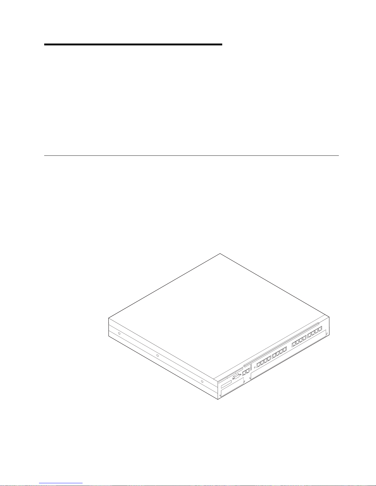
1-1. 8239 Model 1 ................................. 1-1
1-2. 8239 Model 2 ................................. 1-2
1-3. 8239 Dimensions . . . . . . . . . . . . . . . . . . . . . . . . . . . . . . 1-6
2-1. Rotating the Rack-Mounting Brackets ................... 2-3
2-2. Attaching the Cable Management Bracket ................ 2-4
2-3. Connecting Stations to the 8239 ...................... 2-4
2-4. Stack Building . . . . . . . . . . . . . . . . . . . . . . . . . . . . . . . . 2-5
2-5. Power on the 8239 ............................. 2-7
3-1. 16-Port Expansion Feature ......................... 3-1
3-2. RI/RO Module . . . . . . . . . . . . . . . . . . . . . . . . . . . . . . . . 3-2
3-3. Cabling for the Optical Fiber RI/RO Module ............... 3-3
3-4. Cabling for the RJ-45 RI/RO Module ................... 3-4
5-1. 8239 Model 1 LEDs and LCD ....................... 5-1
5-2. 8239 Model 2 LEDs ............................. 5-2
5-3. Port Status LEDs .............................. 5-3
5-4. RI/RO LEDs . . . . . . . . . . . . . . . . . . . . . . . . . . . . . . . . . 5-6
5-5. Stack In/Stack Out LEDs .......................... 5-8
Copyright IBM Corp. 1998 vii
Page 10

viii 8239 Setup and User’s Guide
Page 11

Notices
References in this publication to IBM products, programs, or services do not imply
that IBM intends to make these available in all countries in which IBM operates.
Any reference to an IBM product, program, or service is not intended to state or
imply that only IBM’s product, program, or service may be used. Any functionally
equivalent product, program, or service that does not infringe any of IBM’s
intellectual property rights may be used instead of the IBM product, program, or
service. Evaluation and verification of operation in conjunction with other products,
except those expressly designated by IBM, are the user’s responsibility.
IBM may have patents or pending patent applications covering subject matter in
this document. The furnishing of this document does not give you any license to
these patents. You can send license inquiries, in writing, to the IBM Director of
Licensing, IBM Corporation, 500 Columbus Avenue, Thornwood, NY 10594 USA.
Safety Information
Read this important safety information before using the 8239.
Safety Information Booklet
Danger: Before you begin to install this product, read the safety information
in
Caution: Safety Information—Read This First
safe procedures for cabling and plugging in electrical equipment.
Gevaar: Voordat u begint met de installatie van dit produkt, moet u eerst de
veiligheidsinstructies lezen in de brochure
eerst,
SD21-0030. Hierin wordt beschreven hoe u electrische apparatuur op een
veilige manier moet bekabelen en aansluiten.
Danger: Avant de procéder à l'installation de ce produit, lisez d'abord les
consignes de sécurité dans la brochure
lire au préalable,
connecter les appareils électriques en toute sécurité.
Perigo: Antes de começar a instalar este produto, leia as informações de
segurança contidas em
Primeiro,
instalação de cabos e conexões em equipamentos elétricos.
SD21-0030. Esse folheto descreve procedimentos de segurança para a
, SD21-0030. This booklet describes
PAS OP! Veiligheidsinstructies—Lees dit
ATTENTION: Consignes de sécurité—A
SD21-0030. Cette brochure décrit les procédures pour câbler et
Cuidado: Informações Sobre Segurança—Leia Isto
Copyright IBM Corp. 1998 ix
Page 12
Fare! Før du installerer dette produkt, skal du læse sikkerhedsforskrifterne i
NB: Sikkerhedsforskrifter—Læs dette først
SD21-0030. Vejledningen beskriver den
fremgangsmåde, du skal bruge ved tilslutning af kabler og udstyr.
Gevaar Voordat u begint met het installeren van dit produkt, dient u eerst de
veiligheidsrichtlijnen te lezen die zijn vermeld in de publikatie
Information - Read This First
, SD21-0030. In dit boekje vindt u veilige procedures
Caution: Safety
voor het aansluiten van elektrische appratuur.
VAARA: Ennen kuin aloitat tämän tuotteen asennuksen, lue julkaisussa
Varoitus: Turvaohjeet—Lue tämä ensin
, SD21-0030, olevat turvaohjeet. Tässä
kirjasessa on ohjeet siitä, miten sähkölaitteet kaapeloidaan ja kytketään turvallisesti.
Danger : Avant d'installer le présent produit, consultez le livret
Informations pour la sécurité — Lisez-moi d'abord
, SD21-0030, qui décrit les
Attention :
procédures à respecter pour effectuer les opérations de câblage et brancher les
équipements électriques en toute sécurité.
Vorsicht: Bevor mit der Installation des Produktes begonnen wird, die
Sicherheitshinweise in
Achtung: Sicherheitsinformationen—Bitte zuerst lesen,
IBM
Form SD21-0030. Diese Veröffentlichung beschreibt die Sicherheitsvorkehrungen
für das Verkabeln und Anschließen elektrischer Geräte.
x 8239 Setup and User’s Guide
Page 13

Vigyázat: Mielôtt megkezdi a berendezés üzembe helyezését, olvassa el a
Caution: Safety Information— Read This First,
biztonsági információkat. Ez a könyv leírja, milyen biztonsági intézkedéseket kell
megtenni az elektromos berendezés huzalozásakor illetve csatlakoztatásakor.
Pericolo: prima di iniziare l'installazione di questo prodotto, leggere le
informazioni relative alla sicurezza riportate nell'opuscolo
di sicurezza — Prime informazioni da leggere
il cablaggio ed il collegamento di apparecchiature elettriche.
SD21-0030 könyvecskében leírt
Attenzione: Informazioni
in cui sono descritte le procedure per
Fare: Før du begynner å installere dette produktet, må du lese
sikkerhetsinformasjonen i
SD21-0030 som beskriver sikkerhetsrutinene for kabling og tilkobling av elektrisk
utstyr.
Notices xi
Advarsel: Sikkerhetsinformasjon — Les dette først
,
Page 14
Perigo: Antes de iniciar a instalação deste produto, leia as informações de
segurança
Cuidado: Informações de Segurança — Leia Primeiro
, SD21-0030. Este
documento descreve como efectuar, de um modo seguro, as ligações eléctricas
dos equipamentos.
Peligro: Antes de empezar a instalar este producto, lea la información de
seguridad en
Atención: Información de Seguridad — Lea Esto Primero,
SD21-0030.
Este documento describe los procedimientos de seguridad para cablear y enchufar
equipos eléctricos.
Varning — livsfara: Innan du börjar installera den här produkten bör du läsa
säkerhetsinformationen i dokumentet
först,
SD21-0030. Där beskrivs hur du på ett säkert sätt ansluter elektrisk
Varning: Säkerhetsföreskrifter— Läs detta
utrustning.
xii 8239 Setup and User’s Guide
Page 15
Power Disconnection
Danger: The main power disconnect for this unit is the appliance inlet
located on the back of the machine. Therefore, the machine should be installed in
such a way that the appliance inlet can be accessed.
DANGER. Le dispositif permettant de couper l'alimentation principale de
cette unité se situe à l'arrière de la machine. Ce dispositif doit donc être accessible.
Vorsicht: Der Hauptschalter zur Unterbrechung der Stromversorgung für
diese Einheit ist der Schalter, der sich auf der Rückseite der Maschine befindet. Die
Maschine sollte daher so aufgestellt werden, daß dieser Schalter jederzeit
zugänglich ist.
Pericolo: Per scollegare questa unità, occorre staccare la spina posta sul
retro della macchina; pertanto la macchina deve essere installata in modo tale che
tale spina sia accessibile.
Fare: Denne enheten frakobles hovednettet via apparatinntaket på baksiden
av maskinen. Derfor må maskinen installeres slik at apparatinntaket er lett
tilgjengelig.
Notices xiii
Page 16
Perigo: Para desligar a alimentação principal desta unidade é necessário
desconectar o cabo da tomada eléctrica localizada na parte posterior da máquina.
Por consequência, a máquina deve ser instalada de modo a permitir o fácil acesso
a essa tomada.
ОПАСНО: Разъем для отключения питания данного блока
расположен на задней стенке. Поэтому устанавливайте
машину так, чтобы разъем питания был доступен.
Peligro: El interruptor principal de desconexión de esta unidad es la entrada
de conexión del aparato situado en la parte trasera de la máquina. Por lo tanto, la
máquina debe instalarse de modo que la entrada de conexión del aparato sea
accesible.
FARA: Brytning av huvudströmmen till den här enheten görs vid
elanslutningen på baksidan av maskinen. Placera därför maskinen så att
elanslutningen är lättåtkomlig.
Electronic Emission Notices
Federal Communications Commission (FCC) Statement
Note:This equipment has been tested and found to comply with the limits for a
Class A digital device, pursuant to Part 15 of the FCC Rules. These limits are
designed to provide reasonable protection against harmful interference when the
equipment is operated in a commercial environment. This equipment generates,
uses, and can radiate radio frequency energy and, if not installed and used in
accordance with the instruction manual, may cause harmful interference to radio
communications. Operation of this equipment in a residential area is likely to cause
harmful interference, in which case the user will be required to correct the
interference at his own expense.
Properly shielded and grounded cables and connectors must be used in order to
meet FCC emission limits. IBM is not responsible for any radio or television
interference caused by using other than recommended cables and connectors or by
unauthorized changes or modifications to this equipment. Unauthorized changes or
modifications could void the user’s authority to operate the equipment.
This device complies with Part 15 of the FCC Rules. Operation is subject to the
following two conditions: (1)this device may not cause harmful interference, and
(2)this device must accept any interference received, including interference that
may cause undesired operation.
xiv 8239 Setup and User’s Guide
Page 17

Industry Canada Class A Emission Compliance Statement
This Class A digital apparatus complies with Canadian ICES-003.
Avis de conformité aux normes d'Industrie Canada
Cet appareil numérique de la classe A est conform à la norme NBM-003 du
Canada.
European Community (CE) Mark of Conformity Statement
This product is in conformity with the protection requirements of EU Council
Directive 89/336/EEC on the approximation of the laws of the Member States
relating to electromagnetic compatibility. IBM cannot accept responsibility for any
failure to satisfy the protection requirements resulting from a non-recommended
modification of the product, including the fitting of non-IBM option cards. This
product has been tested and found to comply with the limits for Class A Information
Technology Equipment according to CISPR 22/European Standard EN 55022. The
limits for Class A equipment were derived for commercial and industrial
environments to provide reasonable protection against interference with licensed
communication equipment.
Attention: This is a Class A product. In a domestic environment this product may
cause radio interference in which case the user may be required to take adequate
measures.
Zulassungsbescheinigung laut dem Deutschen Gesetz über die
elektromagnetische Verträglichkeit von Geräten (EMVG) vom 30. August 1995
(bzw. der EMC EG Richlinie 89/336).
Dieses Gerät ist berechtigt in Übereinstimmung mit dem Deutschen EMVG das
EG-Konformitätszeichen - CE - zu führen.
Verantwortlich für die Konformitätserklärung nach Paragraph 5 des EMVG ist die
IBM Deutschland Informationssysteme GmbH, 70548 Stuttgart.
Informationen in Hinsicht EMVG Paragraph 3 Abs. (2) 2:
EN 55022 Klasse A Geräte müssen mit folgendem Warnhinweis versehen werden:
“Warnung: dies ist eine Einrichtung der Klasse A. Diese Einrichtung kann im
Wohnbereich Funkstörungen verursachen; in diesem Fall kann vom Betreiber
verlangt werden, angemessene Maßnahmen durchzuführen und dafür
aufzukommen.”
EN 50082-1 Hinweis: “Wird dieses Gerät in einer industriellen Umgebung betrieben
(wie in EN 50082-2 festgelegt), dann kann es dabei eventuell gestört werden. In
solch einem Fall ist der Abstand bzw. die Abschirmung zu der industriellen
Störquelle zu vergrößern.”
Anmerkung: Um die Einhaltung des EMVG sicherzustellen sind die Geräte, wie in
den IBM Handbüchern angegeben, zu installieren und zu betreiben.
Notices xv
Page 18

Japanese Voluntary Control Council for Interference (VCCI) Statement
This product is a Class A Information Technology Equipment and conforms to the
standards set by the Voluntary Control Council for Interference by Technology
Equipment (VCCI). In a domestic environment this product may cause radio
interference in which case the user may be required to take adequate measures.
Taiwanese Class A Warning Statement
Battery Disposal
The 8239 Model 1 contains a clock module that has an embedded lithium battery.
This battery is not replaceable. Please dispose of this module in accordance with
local ordinances.
Trademarks
IBM and Nways are trademarks of the IBM Corporation in the United States or
other countries or both.
UNIX is a registered trademark in the United States and other countries licensed
exclusively through X/Open Company Limited.
Microsoft, Windows, Windows NT, and the Windows 95 logo are trademarks or
registered trademarks of Microsoft Corporation.
Other company, product, and service names may be trademarks or service marks
of others.
xvi 8239 Setup and User’s Guide
Page 19

Preface
This manual contains information for anyone who is planning to install, configure, or
manage an 8239 Token-Ring Stackable Hub (8239).
How This Manual Is Organized
This manual contains the following sections:
¹ Chapter 1, “Introduction and Planning” on page 1-1 introduces the functions,
models, and physical requirements. It also contains configuration and network
planning information.
¹ Chapter 2, “Installing the 8239 Hardware” on page 2-1 gives instructions for
setting up the 8239.
¹ Chapter 3, “Installing Features” on page 3-1 provides information needed to
install the optional features.
¹ Chapter 4, “Configuration” on page 4-1 describes the configuration process.
¹ Chapter 5, “Problem Determination Procedures” on page 5-1 provides problem
determination procedures and lists all error codes.
¹ Chapter 6, “Concentrator Functions” on page 6-1 describes the concentrator
functions provided by the 8239.
¹ Chapter 7, “8239 Device Management” on page 7-1 explains how to
implement management of the device.
¹ Chapter 8, “Network Management” on page 8-1 contains information about
accessing network management data.
¹ Chapter 9, “Planning Charts” on page 9-1 contains charts to help with planning
for cabling and configuration.
¹ Appendix A, “Warranty Information” on page A-1 provides details about your
warranty.
Related Publications
The following publications are shipped with the product in displayable softcopy form
on the 8239 Token-Ring Stackable Hub Softcopy Library CD-ROM (08L3308):
8239 Token-Ring Stackable Hub Setup and User’s Guide,
8239 Token-Ring Stackable Hub Command Reference,
This CD-ROM is shipped with initial orders for the 8239.
GA27-4209
GA27-4208
These additional publications are shipped in hard copy:
¹
8239 Token-Ring Stackable Hub Quick Reference,
¹
Caution: Safety Information - Read This First,
¹
License Agreement for Machine Code
For general information about token-ring architecture, see
Architecture
Copyright IBM Corp. 1998 xvii
GX27-4047
SD21-0030
, Z125-5468
Token-Ring Network
, SC30–3374.
Page 20

Visit our Web Site
This IBM web page provides product information:
http://www.networking.ibm.com/support
xviii 8239 Setup and User’s Guide
Page 21
Chapter 1. Introduction and Planning
This chapter describes the functions of and the physical requirements for the IBM
8239 Token-Ring Stackable Hub (8239). It also contains planning information.
The 8239 is a stackable concentrator, allowing token-ring stations to share a
network. Up to eight 8239s can be interconnected to form a stack. The stack
connection provides a control path as well as a token-ring data path. The control
path is an internal token-ring segment used by the stack units to communicate with
each other. The token-ring data path connects the stack units into a shared
token-ring network for user traffic. The 8239 is available in two models and
provides a range of network management functions.
Models
Both models of the 8239:
¹ Support basic concentrator functions, such as attachment of port stations,
beacon recovery, address-to-port mapping, and so on
¹ Attach up to 16 workstations
¹ Allow you to attach up to 32 workstations with an optional port expansion
feature
¹ Provide configuration and status information for each device through an
out-of-band connection
Figure 1-1. 8239 Model 1
Copyright IBM Corp. 1998 1-1
Page 22

Features
Figure 1-2. 8239 Model 2
The Model 1, in addition:
¹ Supports additional concentrator functions
¹ Provides network management functions
¹ Supports in-band connectivity
¹ Supports connection to other compatible concentrators
The following optional features are available for the 8239.
¹ 16-Port Expansion Feature
The 16-Port Expansion Feature contains 16 RJ-45 token-ring ports, increasing
the supported number of ports in a single 8239 from 16 to 32. The 16-Port
Expansion Feature can be installed in the feature slot of the 8239.
¹ RI/RO Module (Model 1 only)
Use the Ring In/Ring Out Module (RI/RO Module) to connect to another 8239
stack or to other compatible concentrators, such as:
– Token-Ring 8228 Multistation Access Unit
– 8230 Token-Ring Network Controlled Access Unit
– 8238 Token-Ring Stackable Hub
– 8260 Nways Multiprotocol Switching Hub
It is installed in the RI/RO Module slot on the Model 1. There are two types of
RI/RO Module:
– RJ-45 RI/RO Module, providing an RJ-45 copper interface
– Optical Fiber RI/RO Module, providing an ST-connector optical fiber
interface
1-2 8239 Setup and User’s Guide
Page 23

Configuration
The 8239 is shipped with a default configuration. If this configuration is acceptable,
you need only power on the 8239 and connect the cables. The configuration
parameters along with their default values are listed in “Configuration Parameters”
on page 4-9.
If you need to change the configuration, you can do so using:
¹ EIA-232 terminal interface (both models)
¹ Telnet terminal interface (Model 1 only)
¹ SNMP (Model 1 only)
¹ BOOTP (Model 1 only)
¹ Configuration setup file loaded via XMODEM (both models) or TFTP (Model 1
only)
Concentrator Functions
Each 8239 provides 16 RJ-45 token-ring ports. Cabling may be either unshielded
twisted pair (UTP) or shielded twisted pair (STP). The 8239 has an expansion slot
that allows you to add 16 additional RJ-45 ports, for a total of 32 ports. Up to eight
8239 can be connected to form a single stack using the stack-in and stack-out
ports. Thus, there can be up to 256 token-ring ports supported in an 8239 stack.
Any combination of 8239 Model 1s and 8239 Model 2s can make up a stack.
The 8239 provides address-to-port mapping information that identifies which MAC
addresses are attached to which ports on the 8239. Fanout devices and MAC-less
devices attached to 8239 ports also are supported by this mapping feature.
The 8239 provides port security. Port security allows you to identify specific MAC
addresses that are permitted to insert at a given port. You can configure a port to
respond to a security intrusion by:
¹ Disabling the port
¹ Reporting the intrusion attempt
¹ Disabling and reporting the intrusion attempt
The 8239 provides automatic beacon recovery when hard-error faults occur.
Hard-error faults are automatically detected and isolated to minimize the impact on
the network.
Device and Network Management
The 8239 can be managed in these ways:
¹ Out-of-band access through the EIA-232 port
¹ In-band access using Telnet, SNMP, PING, and TFTP (8239 Model 1 only)
Device management consists of configuring the stack, obtaining status information
from the stack, and loading code on the stack.
The network management functions supported by the 8239 Model 1 are:
¹ IEEE 802.5 Token Ring MIB
Chapter 1. Introduction and Planning 1-3
Page 24

¹ MIB II
¹ Remote Monitoring (RMON)
¹ RMON 2
¹ Enterprise Communications Analysis Module (ECAM)
¹ IBM Token Ring Surrogate MIB and Surrogate Trap MIB
Cable Types and Distances
This section gives information about supported cable types and maximum cable
distances.
Ports
Table 1-1 shows the types of cable and maximum distances supported for port
cabling.
Table 1-1. Port Cabling
Cable Type 4-Mbps Ring Speed 16-Mbps Ring Speed
UTP, ScTP, or FTP Cat 3 250 m (820 ft) 100 m (328 ft)
UTP, ScTP, or FTP Cat 4 425 m (1394 ft) 210 m (689 ft)
UTP, ScTP, or FTP Cat 5 425 m (1394 ft) 225 m (738 ft)
STP or STP-A 750 m (2460 ft) 375 m (1230 ft)
Stack Unit Cabling
You can install up to eight 8239s in a stack, using any combination of 8239 Model
1s and 8239 Model 2s in the stack. Use standard TIA/EIA/ANSI 568A or ISO/IEC
11801 Category 5 cable for your stack.
Determining Maximum Cable Length
Each of the 8239s in a stack can be up to 25m (82 ft) apart without regard to the
total distance among all 8239s in the stack. If distances over 25m are required,
they are supported provided that the sum of all of the stack cable lengths minus the
length of the shortest stack cable does not exceed 210 M (689 ft). For example,
four 8239s have the following stack cables connecting them to form a stack:
Cable 1 connects stack unit 1 to stack unit 2 1 m
Cable 2 connects stack unit 2 to stack unit 3 25 m
Cable 3 connects stack unit 3 to stack unit 4 25 m
Cable 4 connects stack unit 4 to stack unit 1 150 m
To see if this configuration is allowable, use this formula:
(Total length of stack cables) - (length of shortest cable) < 210 m
Substituting the values in the example in this formula:
1 + 75 + 90 + 150 - 1 = 200
Because 200 m is less than 210 m, this configuration is allowable. In this case,
even though there are lengths of cable that are greater than 25 m, the configuration
is still acceptable because the total distance is less than 210 m.
Attention: To prevent ring disruptions, be sure you connect Stack-In and Stack-Out
cables at both ends.
1-4 8239 Setup and User’s Guide
Page 25

RI/RO Module
This section describes cabling for the RJ-45 RI/RO Module and the Optical Fiber
RI/RO Module.
RJ-45 RI/RO Module
Table 1-2 shows the types of cable and maximum distances supported for the
RJ-45 RI/RO Module.
Table 1-2. RJ-45 RI/RO Module Cabling
Cable Type 4-Mbps Ring Speed 16-Mbps Ring
Speed
UTP, ScTP, or FTP Cat 3 250 m (820 ft) 100 m (328 ft)
UTP, ScTP, or FTP Cat 4 425 m (1394 ft) 210 m (689 ft)
UTP, ScTP, or FTP Cat 5 425 m (1394 ft) 225 m (738 ft)
STP or STP-A 750 m (2460 ft) 375 m (1230 ft)
Optical Fiber RI/RO Module
The recommended maximum fiber length that can be used between Ring In and
Ring Out fiber connections is 2 km (1.2 miles) of 62.5/125-micron multimode optical
fiber cable. This distance applies to both 4-Mbps and 16-Mbps rings. See
Cabling System Optical Fiber Planning and Installation
information about optical fiber.
Physical Specifications
This section gives the physical specifications, environmental requirements, and
power requirements of the 8239.
Dimensions
Figure 1-3 on page 1-6 shows the exterior dimensions of the 8239.
IBM
, GA27–3943, for more
Chapter 1. Introduction and Planning 1-5
Page 26
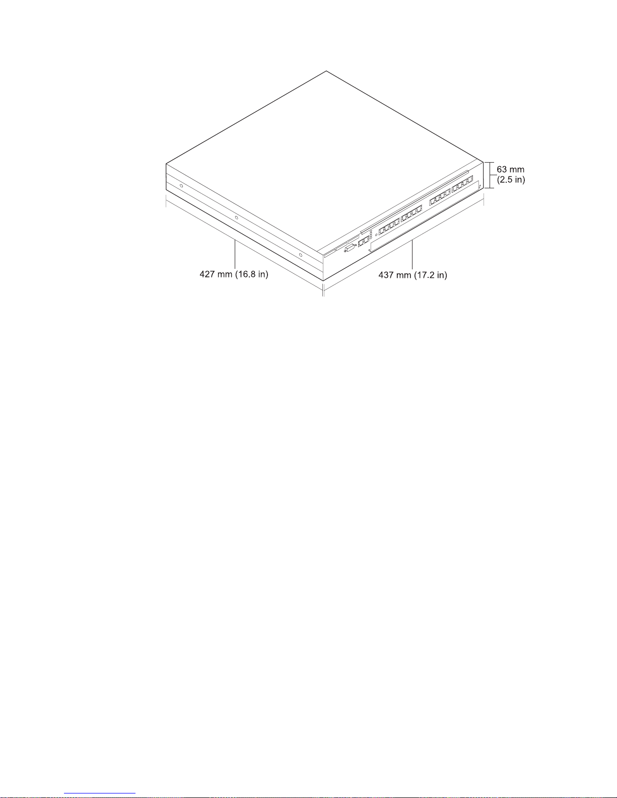
Figure 1-3. 8239 Dimensions
Placement
The 8239 can be placed on a tabletop or installed in a customer-supplied rack.
To surface-mount the 8239, choose a flat horizontal surface sturdy enough to
support the weight of the 8239. Do not mount the 8239 vertically.
The 8239 can be installed in a standard, open, EIA 19-in. rack in a wiring-closet
environment. The rack must meet the requirements of ANSI/EIA RS-310-C. The
8239 requires 1.5 rack units.
Weight
8239 Model 1: 7.0 kg (15.4 lb) when empty; 7.4 kg (16.4 lb) when fully loaded
8239 Model 2: 7.0 kg (15.4 lb) when empty; 7.4 kg (16.4 lb) when fully loaded
Service Clearances
Front Adequate space to view LEDs
Sides Minimum of 50 mm (2 in.) for cooling purposes
Rear Minimum of 130 mm (5 in.) to provide for cables
Environmental Requirements
Operating Temperature 10°— 40° C (50°—104° F)
Storage Temperature -40°—60° C (-40°—140° F)
Humidity 20°—85%
1-6 8239 Setup and User’s Guide
Page 27

Power Requirements
The 8239 requires input ac voltage within the range of 88 V ac to 265 V ac at a
frequency of 47 Hz to 63 Hz.
The maximum power consumption of an 8239 that is fully populated with features is
85 W.
Chapter 1. Introduction and Planning 1-7
Page 28

1-8 8239 Setup and User’s Guide
Page 29

Chapter 2. Installing the 8239 Hardware
This chapter provides instructions for setting up the 8239.
Before installing the 8239, be sure to read “Safety Information” on page ix.
Preparing for Setup
Complete the following tasks before beginning the setup process:
¹ Verify that appropriate power outlets are available.
¹ Gather network documentation identifying devices and specifying port
connections. The network administrator is responsible for network planning.
Worksheets for planning your 8239 installation are provided in Chapter 9,
“Planning Charts” on page 9-1.
¹ You will need access to a local ASCII terminal or to the terminal that is being
used for remote access.
Verifying the Shipment
After you have unpacked the shipping container, use the following Inventory
Checklist to verify that you have the items listed.
Inventory Checklist
¹ Hardware
__ 8239 Model 1 or Model 2
__ Power cord (U.S., Canada, and Latin America)
__ Stack Cable (standard Category 5 UTP)
__ Cable management bracket
¹ Media
__CD containing this information:
8239 MIB
¹ Printed publications
__
__
__
__
__
8239 Token-Ring Stackable Hub Setup and User’s Guide
8239 Token-Ring Stackable Hub Command Reference
License Agreement for Machine Code
8239 Token-Ring Stackable Hub Quick Reference
Caution: Safety Information - Read This First
Network Management
README file
trial offer
(this book)
Copyright IBM Corp. 1998 2-1
Page 30

Installing Features
The following features may be installed in the 8239:
¹ Optical Fiber RI/RO Module (Model 1 only)
¹ RJ-45 RI/RO Module (Model 1 only)
¹ 16-Port Expansion Feature
For instructions for the installation of these features, go to Chapter 3, Installing
Features.
Placing the 8239
The 8239 can be placed on a tabletop or installed in a customer-supplied rack.
If you are installing this 8239 in a rack, go to “Rack-Mounting the 8239.” Otherwise,
continue with “Surface-Mounting the 8239.”
Surface-Mounting the 8239
Place the 8239 on a flat horizontal surface sturdy enough to support its weight. The
8239 is not designed for vertical mounting.
Continue with “Connecting the Cables” on page 2-4.
Rack-Mounting the 8239
The 8239 can be installed in a standard, open, EIA 19–in. rack in a wiring-closet
environment.
2-2 8239 Setup and User’s Guide
Page 31

Figure 2-1. Rotating the Rack-Mounting Brackets
1. Using a Phillips screwdriver, remove the four screws, two on each side, that
attach the mounting brackets to the sides of the 8239, as shown in Figure 2-1.
2. Rotate the brackets and reattach them.
3. Refer to your network documentation to determine where in the rack to mount
the 8239.
4. Gather the rack-mounting screws (not provided) and place them within reach.
5. Hold the 8239 in position in the rack and start the lower of the two screws that
will secure the left bracket.
6. On the right side, align the lower screw holes in the mounting bracket and the
cable management bracket with the correct hole of the rack; then start the
screw as shown in Figure 2-2 on page 2-4.
Chapter 2. Installing the 8239 Hardware 2-3
Page 32

Figure 2-2. Attaching the Cable Management Bracket
7. Tighten the screws on each side.
Connecting the Cables
Use this section to connect cables to the 8239 and any attaching devices.
Connecting Stations to the 8239
Figure 2-3. Connecting Stations to the 8239
1. Refer to your network documentation to determine each cable’s port
assignment.
2. Connect the lobe cable (not provided) to a lobe port on the 8239.
2-4 8239 Setup and User’s Guide
Page 33

Cabling a Stack
3. Label the cable at the lobe port with a unique identifier so that it will be easy to
identify the location of the device at the other end of the cable should you have
to troubleshoot a network problem.
4. Connect the other end of the cable to the end station faceplate or other
intermediate connection point, as required.
Label the cables at the attaching-device end.
Note: The stack cable shipped with the 8239 Model 1 is longer than the cable
shipped with the Model 2, providing the means to connect the top 8239 to
the bottom 8239.
To build a hub stack containing two to eight 8239s:
1. Beginning with the 8239 at the top of the stack, use a stack cable to connect
stack OUT on the top 8239 to stack IN on the next hub below in the stack.
Figure 2-4. Stack Building
2. Using stack cables, continue to connect stack OUT on each 8239 to stack IN
on the next 8239 in the stack.
3. Use the stack cable to connect stack IN on the top 8239 to stack OUT on the
bottom 8239.
To prevent network disruptions, be sure you connect stack cables at both ends.
Connecting an ASCII Terminal or Modem to the EIA-232 Port
If you are going to access the 8239 without using the data network, you must
attach either an ASCII terminal for local access to the 8239 or a modem for remote
access.
ASCII Terminal
To attach an ASCII terminal, follow these steps:
1. Connect one end of the special null-modem cable (not provided) to the EIA-232
port of the 8239 that is going to be used.
2. Connect the other end of the cable to the communications port of your ASCII
terminal
Chapter 2. Installing the 8239 Hardware 2-5
Page 34

Modem
To attach a modem, follow these steps:
1. Unpack the modem and install it according to the manufacturer’s instructions.
2. Connect one end of the standard modem DTE cable (not provided) to the
EIA-232 port on the 8239.
3. Connect the other end of the cable to the modem.
4. Configure the modem to use the same settings as those on the 8239 you are
using (refer to “Management Using Emulation Software” on page 4-1).
5. Place the modem in auto-answer mode.
6. Set up the remote modem and data terminal.
7. Establish a modem link as described in the modem user documentation.
Note: Configuration command syntax varies from modem to modem. Make sure
that the modem has the following characteristics:
¹ asynchronous mode
¹ disable modem responses
¹ disable flow control (for example, AT \Q)
¹ disable echo (for example, AT Q1)
¹ auto-answer mode on second ring (for example, AT S0=2)
After configuring the modem, save its configuration.
Powering On the 8239
2-6 8239 Setup and User’s Guide
Page 35

Figure 2-5. Power on the 8239
1. Connect the power cord to the connector at the rear of the 8239.
2. Plug the power cord into the power outlet.
Because the 8239 has no power switch, the power-on self-test (POST) begins as
soon as you plug in the power cord. POST requires up to 2 minutes. At the end of
POST, the LCD on the 8239 Model 1 shows the operational code version for about
5 seconds. A successful power-on is indicated when the green OK light-emitting
diode (LED) is lit and the yellow OK LED is off.
Chapter 2. Installing the 8239 Hardware 2-7
Page 36

2-8 8239 Setup and User’s Guide
Page 37

Chapter 3. Installing Features
16-Port Expansion Feature
To install or remove a 16-Port Expansion Feature, follow the directions in this
section. The 16-Port Expansion Feature is hot pluggable, so you do not need to
disconnect the 8239 power cord.
Figure 3-1. 16-Port Expansion Feature
Removing a 16-Port Expansion Feature
1. If you intend to replace the 16-Port Expansion Feature, label the cables
attached to it to ensure that you reconnect the cables correctly.
2. Disconnect the cables from the 16-Port Expansion Feature.
3. Loosen the two thumbscrews by turning them counterclockwise until the screws
are loose enough to remove the card from the 8239.
4. Remove the 16-Port Expansion Feature from the 8239 by pulling on the thumb
screws.
5. If you are not replacing the 16-Port Expansion Feature immediately, install an
expansion slot cover.
Installing a 16-Port Expansion Feature
Perform these steps to install a 16-Port Expansion Feature:
1. If a 16-Port Expansion Feature was not already installed in this 8239, remove
the slot cover and store it in a safe place.
2. Slide the 16-Port Expansion Feature along the grooves in the slot until it is
seated and flush with the front panel.
3. Tighten the thumbscrews by turning them clockwise.
4. After the adapter is seated, all of the yellow port LEDs are on briefly, indicating
that diagnostic tests are in progress.
5. The diagnostic tests for the 16-Port Expansion Feature will complete in less
than 5 seconds.
Copyright IBM Corp. 1998 3-1
Page 38

RI/RO Module
6. Use the DISPLAY INVENTORY terminal interface command to verify that the
8239 recognizes the 16-Port Expansion Feature.
To install or remove a Ring In/Ring Out Module, follow the directions in this section.
Attention: You must power off the 8239 before installing or removing a Ring
In/Ring Out Module.
You do not need to remove the 8239 from a rack to remove or install a RI/RO
Module.
Figure 3-2. RI/RO Module
Removing a RI/RO Module
1. Remove power from the 8239 by unplugging the power cord.
2. If you intend to replace the RI/RO Module, label the cables attached to it. This
precaution will ensure that you reconnect the cables correctly.
3. Disconnect the cables from the RI/RO Module.
4. Loosen the two thumbscrews by turning them counterclockwise until the screws
are loose enough to remove the module from the 8239.
5. Pull the RI/RO Module along the grooves of the guide rail and remove it from
the 8239.
6. If you are not replacing the RI/RO Module immediately, install a slot cover and
provide power to the 8239.
3-2 8239 Setup and User’s Guide
Page 39

Installing a RI/RO Module
Perform these steps to install a RI/RO Module:
1. Remove power from the 8239 by unplugging the power cord.
2. If a RI/RO Module was not already installed in this 8239, remove the slot cover
and store it in a safe place.
3. Slide the module into the slot along the grooves of the guide rail until it is
seated and flush with the front panel.
4. Tighten the thumbscrews by turning them clockwise.
5. Connect the cables connecting RI on the 8239 RI/RO Module to RO on the
external device and RO on the 8239 RI/RO Module to RI on the external
device.
¹ For the Optical Fiber RI/RO Module:
Figure 3-3. Cabling for the Optical Fiber RI/RO Module
¹ For the RJ-45 RI/RO Module:
Chapter 3. Installing Features 3-3
a. Connect the RI receive port to the RO transmit port on the external
device.
b. Connect the RI transmit port to the RO receive port on the external
device.
c. Connect the RO receive port to the RI transmit port on the external
device.
d. Connect the RO transmit port to the RI receive port on the external
device.
Page 40

Figure 3-4. Cabling for the RJ-45 RI/RO Module
a. Connect RI on the 8239 to RO on the external device.
b. Connect RO on the 8239 to RI on the external device.
Attention:
¹ Be sure that you connect RI/RO cables at both ends before enabling these
interfaces. Any of these interfaces that are not going to be used should be
administratively disabled.
¹ Use caution when implementing a network with more than one RI/RO
interface per stack. Multiple RI/RO connectors between two ring segments
or between two 8239 Model 1s in the same stack can cause undesirable
results, such as a division of the ring into two independent segments.
6. Provide power to the 8239.
The RI/RO ports are disabled by default. To enable them, issue the ENABLE
RING_IO command or the UNWRAP RING_IO command; these commands are
equivalent.
3-4 8239 Setup and User’s Guide
Page 41

Chapter 4. Configuration
This chapter describes the configuration procedures you need to perform before
you can manage the 8239.
When you install an 8239, it contains factory-default parameters. Depending on
your needs, you might want to change these defaults. For a listing of the default
values, go to “Configuration Parameters” on page 4-9.
Using the Command Interface
Employ the command interface using a terminal emulation program that supports
VT100 emulation or using Telnet over an IP connection.
Login Access
To use the terminal interface, you must enter a login name and password. There
are two access types associated with a login name:
¹ Admin, which allows you to issue all commands
¹ User, which allows you to issue a subset of the commands allowed under
Admin access.
Configuration changes made with User access can be saved only under Admin
access. The SAVE command is not allowed for User access.
The default login name is “admin” with no password. It is recommended that you
change the 8239 login password to a more secure password.
Management Using Emulation Software
You can use terminal emulation software in one of two ways:
¹ Using a direct, null-modem cable connection
¹ Using a public telephone network via a modem and a standard EIA-232 cable
The default terminal baud setting is 9600 bps. This value can be changed using
the SET TERMINAL BAUD command. Initialization and diagnostic messages are
displayed at 9600 bps; once the 8239 is operational, the configured terminal baud
setting is used.
Using a Null-Modem Cable
To communicate with the 8239 for the first time, configure the terminal emulation
application with:
¹ 9600 bps
¹ No parity
¹ 8 data bits
¹ 1 stop bit
¹ No flow control
¹ VT100 emulation
¹ The communications port of the workstation that you have configured in the
emulation software
Copyright IBM Corp. 1998 4-1
Page 42

Using a Modem
If you will be communicating with the 8239 by means of a modem connection, you
will need to install a second modem and connect it to your workstation.
Configure the terminal emulation application with:
¹ 9600 bps
¹ No parity
¹ 8 data bits
¹ 1 stop bit
¹ No flow control
¹ VT100 emulation
¹ The workstation’s communication port that will be used
Establishing a Session
To establish a session:
1. Invoke emulation software to establish direct connection by means of the
null-modem cable, or invoke the emulation software and dial the number of the
modem attached to the 8239.
2. After the connection is established, you will see either:
¹ The login prompt or trap messages (if the 8239 is already powered on)
¹ Diagnostic messages (if you provide power after establishing the
connection)
3. Press Enter two or three times.
4. At the login prompt, type admin and then press Enter (ADMIN is the default
user name).
5. You are now logged on.
Management Using Telnet
You can access the 8239 in-band using Telnet to an 8239 Model 1. To configure
the 8239 Model 1 for in-band connectivity, go to “Configuring the 8239 for In-Band
Connectivity” on page 4-5.
Command Interface Conventions
The main panel of the command interface for an 8239 Model 1 is shown below.
8239 Login Prompt
Login:admin
Password:mypassword
Main Menu - Accepted inputs:
1) bootp 10) replicate
2) clear 11) reset_hub
3) disable 12) restore_to_factory_default
4) display 13) retrieve
5) enable 14) save
6) help 15) set
7) load 16) script
8) logout 17) unwrap
9) ping 18) wrap
Type 'help' for information
?=Help>
4-2 8239 Setup and User’s Guide
Page 43

Note: When the password is null (the default value), the line that prompts for
password may not appear.
Once you have logged on to the 8239, manage the stack using the command
interface. Use these guidelines, special keys, and short cuts:
¹ Pressing Esc returns you to the terminal prompt.
¹ Pressing shift and ? displays a list of the values that you can enter for a
particular command.
¹ Default values or current settings are shown in brackets.
¹ Pressing Enter accepts the value shown in brackets.
¹ Commands are not case sensitive.
¹ Commands can be issued by:
– Typing the entire command.
– Typing part of the command and pressing the space bar.
– Typing the number shown next to the command. The numbers representing
a command are not the same on the 8239 Model 1 and the Model 2.
¹ Pressing Tab selects the first command that matches what you typed.
Repeatedly pressing Tab cycles through the possible commands that match
what you typed.
¹ Entering help at the terminal prompt displays hints about performing routine
tasks.
Examples
The following table describes how to perform some common management tasks
using the terminal interface. The examples assume this stack configuration:
¹ The stack consists of one 8239 Model 1 and two 8239 Model 2s.
¹ The 8239 Model 1’s hub ID is 1; the hub IDs of the 8239 Model 2s are 2 and 3.
¹ Hub 1 contains the RI/RO Module.
¹ IP is to be configured on hub 1. The IP address is 9.197.4.67, the subnet mask
is 255.255.255.0, and the default gateway is 9.197.4.1.
¹ The ASCII terminal is connected to the 8239 Model 1s (hub 1) EIA-232 port.
Chapter 4. Configuration 4-3
Page 44

Task Action
Remove an external device and its
ports from the stack data ring
Insert an external device and its ports
into the stack data ring
Remove hub 2 from the stack data
ring
Insert hub 2 into the stack data ring Type unwrap data_io both 2 and press
Set up IP on hub 1 Type set ip 1 and press Enter.
Get status for the stack Type display stack and press Enter.
Get status for hub 2 Type display hub 2 and press Enter.
Get status for port 4 on hub 2 Type display port 2.4 and press Enter.
Enable all ports on hub 1 Type enable port 1.all and press Enter.
Disable port 4 on hub 2 Type disable port 2.4 and press Enter.
Type wrap ring_io both 1 and press Enter.
Type unwrap ring_io both 1 and press
Enter.
Type wrap data_io both 2 and press Enter.
Enter.
When prompted, enter the following
information, pressing Enter after each value:
IP address: Type 9.197.4.67
Subnet mask: Type 255.255.255.0
Default gateway: Type 9.197.4.1
Verifying, Saving, and Restoring Parameters
Verifying Parameters
To verify parameters that you have entered, type the appropriate DISPLAY
command.
Saving Parameters
If you change configuration settings and then the 8239 Model 1 loses power or is
reset before you save the changes, the changes are lost; the last-saved
configuration settings are used. For this reason, you should save configuration
information frequently.
To save the current configuration for all the 8239s in the stack, type save and
press Enter.
Restoring Parameters
To restore the last-saved configuration for all hubs in the stack, reset the 8239
without saving the configuration.
Configuring the 8239
This section explains how to configure the 8239 for:
¹ Out-of-band connectivity
¹ In-band connectivity
¹ Network monitoring
See “Configuration Parameters” on page 4-9 for a list of configuration parameters.
4-4 8239 Setup and User’s Guide
Page 45

Configuring the 8239 for Out-of-Band Connectivity
The 8239 supports out-of-band access on both models through the EIA-232 port.
You can attach either an ASCII terminal for local access or a modem for remote
access. The 8239 default settings support out-of-band connectivity. To change any
configuration settings, use the SET TERMINAL command. See “Connecting an
ASCII Terminal or Modem to the EIA-232 Port” on page 2-5 for instructions for
connecting to the EIA-232 port. See “Using the Command Interface” on page 4-1
for information about the command interface.
Configuring the 8239 for In-Band Connectivity
In-band connectivity lets you access the 8239 Model 1 from a remote station using
the Token-Ring network rather than an EIA-232 port. In order to use in-band
connectivity, the 8239 Model 1 must be configured with IP information. You can
configure IP information initially using either of these methods:
¹ BOOTP
¹ Terminal interface commands via the EIA-232 port
BOOTP
If you do not plan to use BOOTP, you should use the DISABLE BOOTP command
in order to reduce network traffic. Continue with this section only if you are
interested in in-band connectivity; otherwise, go to “Using the Command Interface”
on page 4-1.
BOOTP (boot protocol) is a user datagram protocol/internet protocol
(UDP/IP)-based protocol that allows a 8239 Model 1 to obtain IP information with
the assistance of a BOOTP server; with the IP information, the 8239 can use
in-band connectivity. The 8239 supports BOOTP to facilitate the configuration of
newly installed stacks in remote locations. Every 8239 Model 1 is shipped with the
BOOTP protocol enabled.
If your installation has only 8239 Model 2s, in-band connectivity is not supported.
Configuration Using BOOTP:
BOOTP request over IP when it is powered on or reset. The BOOTP server, using
information from its BOOTPTAB file, provides the 8239 Model 1 with configuration
information. In addition to obtaining the IP address and the subnet mask, the 8239
Model 1 can attach to a configuration server to obtain a configuration file. The
configuration file is an ASCII file containing 8239 commands. The commands are
executed as soon as the configuration file is transferred via TFTP to the 8239. The
8239 Model 1 updates its configuration with the information contained in the
BOOTP message. The following example of a BOOTPTAB file entry contains
configuration information for the 8239:
ibm8239hub1:ha=0006298f0490:ip=200.0.0.163:sm=255.255.255.0
:gw=200.0.0.150:sa=200.0.0.150:bf=/tmp/hub1.pfl:ht=6
where
A newly installed 8239 Model 1 broadcasts a
ha
ip
sm
Chapter 4. Configuration 4-5
Is the hardware address of the 8239
Is the IP address of the 8239
Is the subnet mask of the 8239
Page 46

gw
sa
bf
ht
Configuration information obtained from the BOOTP server is not saved unless you
issue a SAVE command.
If your network administrator is using BOOTP to configure network devices, contact
the administrator to determine if you need to make any configuration changes.
Is the default gateway
Is the server IP address from which the configuration file is transferred
via TFTP
Is the configuration file name
Is the hardware type (“6” specifies Token Ring)
Terminal Interface Commands Through the EIA-232 Port
To remotely manage the 8239 or remotely monitor the network using the EIA-232
port, set the IP addresses of the Management Interface hub:
¹ set ip
hub_id ip_address subnet_mask default_gateway
Management Interface Insertion
Make sure that the Management Interface is inserted into the ring:
set management_interface administrative_mode enable
hub_id
SNMP Access
1. Set the community table information, if appropriate, using the SET
COMMUNITY command. Telnet does not require this information.
2. Set the access control list information, if appropriate, using SET ACCESS
ACCESS_CONTROL_LIST
Note: Because the initial state grants wide access to well-known communities,
it is recommended that you change the 8239 default configuration to a
more secure configuration.
3. Set the trap community information, if appropriate, using SET
TRAP_COMMUNITY.
Changing Token-Ring Options
By default, the 8239 Model 1 is configured as a station on the Token-Ring network
using the ring speed that was configured for the hub and the default MAC address.
However, if you want, you can:
¹ Specify a locally administered MAC address
The 8239 Model 1 is produced with a factory-set MAC address. If you want to
use a locally administered MAC address, follow these steps.
1. Specify the MAC address:
set management_interface locally_administered_address
mac_address_value
hub_id
2. Specify the use of the locally administered MAC address:
4-6 8239 Setup and User’s Guide
set management_interface mac_address_type locally_administered
hub_id
Page 47

Changing the MAC address type to locally administered causes the
Management Interface to close and reopen its adapter.
¹ Set other Token-Ring options.
To set other Token-Ring network options, issue the appropriate SET
MANAGEMENT_INTERFACE command.
Configuring for Network Monitoring
To configure the 8239 for network monitoring, enter these commands.
1. If you are going to use in-band management, configure the 8239 according to
the instructions in “Configuring the 8239 for In-Band Connectivity” on page 4-5.
2. Enable the data-gathering functions that you need:
¹ To enable the 8239 for RMON, go to “Configuring RMON.”
¹ To configure the 8239 as a surrogate function, go to “Configuring for the
Surrogate Agent.”
Configuring RMON
To configure RMON:
¹ Assign IP information if you are accessing RMON information via in-band
connectivity. The RMON manager must have a physical path to the 8239’s
RMON probe.
¹ For security reasons, you may want to change the default community names
and set up access control lists
¹ If source routing is used on the segment and an RPS is not on the ring, you
must set the ring segment number in order for the RMON source routing
statistics to be accurate. For information about setting the ring segment
number, see “Enabling RPS” on page 4-8.
By default, all RMON groups are enabled and some RMON groups are set up
automatically. You can disable individual RMON groups using a terminal interface
command or via SNMP through the 8239 private MIB. For more information, go to
Chapter 7, 8239 Device Management.
Example:
Manager — Remote Monitor (ReMon), follow these steps.
1. Make sure that the 8239 Model 1 that is acting as an RMON probe is
configured with the appropriate IP information by using the DISPLAY IP
ADDRESS command. If a change is necessary, configure the IP information
using the following command:
To configure the 8239 to communicate with an Nways Campus
set ip
hub_id ip_address subnet_mask default_gateway
2. Follow the instructions provided with ReMon to configure or add a device or
probe.
Configuring for the Surrogate Agent
Enabling the Token-Ring surrogate function involves enabling the surrogate group
and, possibly, the CRS, REM, and RPS groups.
Note that almost all information associated with the surrogate agent can also be
accessed via SNMP through the IBM TR Surrogate MIB. Accessible only through
the 8239 MIB are:
Chapter 4. Configuration 4-7
Page 48

¹ surrogate group administrative mode
¹ rps_traps administrative mode
Enabling the Surrogate Group:
Use one of these methods:
¹ Issue this command:
set management_interface surrogate_group enable
¹ Issue this command:
enable tr_surrogate surr_status surr_admin
¹ Use SNMP through the IBM 8239 TR Hub MIB.
Enabling REM
1. Enable the surrogate group as explained in “Enabling the Surrogate Group.”
2. Enable the REM function using this command:
enable tr_surrogate surr_status rem_admin
3. Enable each REM flag that you need using this command:
enable tr_surrogate rem_status
option
Note: rem_traps defaults to enabled; all other flags default to disabled.
Enabling CRS
1. Enable the surrogate group as explained in “Enabling the Surrogate Group.”
2. Use this command to enable the CRS function:
enable tr_surrogate surr_admin crs_admin
3. Enable the CRS to report topology change traps:
enable tr_surrogate crs_traps
The default value for crs_traps is enabled.
Enabling RPS
1. Enable the surrogate group as explained in “Enabling the Surrogate Group.”
2. Enable RPS using this command:
enable tr_surrogate surr_admin rps_admin
3. Use this command to enable RPS to report new stations inserted into the ring:
enable tr_surrogate rps_traps
The default value for rps_traps is enabled.
RPS does not become active until you set the ring segment number. A ring
segment number is the part of the virtual storage ring address needed to refer to a
segment. It is used for identification of Token-Ring segments that are being
remotely monitored. Set the ring segment number if the 8239 Model 1 is acting as
the Ring Parameter Server, or if there is no Ring Parameter Server on the segment
and you are collecting RMON source routing statistics. Use the Token-Ring
Surrogate function to identify or set a ring segment number.
The ring segment number can also be obtained with the Aspen Config MIB.
4-8 8239 Setup and User’s Guide
Page 49

To set the ring segment number, use one of these methods:
¹ Enter the following command:
set tr_surrogate segment_number
segment_number hub_id
¹ Use an application that supports SNMP or use a MIB browser to set the value
in the Token_Ring Surrogate MIB.
Configuration Parameters
The following table lists all 8239 parameters, their defaults, and whether they are
configurable. An asterisk following a parameter means that the parameter is
configurable from both an 8239 Model 1 and Model 2; otherwise, a parameter is
configurable from a Model 1 only.
Parameters that are not configurable provide status and information. If a parameter
is configurable and the default value is “N/A”, there is no default value and the
parameter must be set. If a parameter is not configurable and the default is “N/A”,
the parameter is read only; the value is provided by the product.
These parameters are accessible using the command interface or using SNMP
through the 8239 MIB.
Parameter Default Value Configurable
Access Control list (level 4) Any IP address with level 4
community name
Access Control list (level 3) Any IP address with level 3
community name
Access Control list (level 2) Any IP address with level 2
community name
Access Control list (level 1) Any IP address with level 1
community name
Beacon threshold* 8 Yes
BOOTP power-up mode ENABLED Yes
BOOTP server IP address 255.255.255.255 Yes
Clock Initially, JAN 21 00:00:00 1997 Yes
Community name (level 1) PUBLIC Yes
Community name (level 2) RMON Yes
Community name (level 3) USER Yes
Community name (level 4) ADMIN Yes
Control In administrative mode* UNWRAPPED Yes
Control Out administrative mode* UNWRAPPED Yes
Data In administrative mode* UNWRAPPED Yes
Data Out administrative mode* UNWRAPPED Yes
Dot5 group DISABLED Yes
Event script N/A Yes
Group mode* N/A Yes
Yes
Yes
Yes
Yes
Chapter 4. Configuration 4-9
Page 50

Parameter Default Value Configurable
Group name* N/A Yes
Group port* N/A Yes
Hub ID* Lowest available value Yes
IP address 0.0.0.0 Yes
IP default gateway 0.0.0.0 Yes
IP subnetwork mask 0.0.0.0 Yes
Login user* ADMIN with no password ID and password
can be configured
Management Interface active monitor
participation
Management Interface Adapter microcode
version
Management Interface Adapter status READ-ONLY No
Management Interface administrative mode ENABLED Yes
Management Interface ARP resolve method SOURCE-ROUTE Yes
Management Interface burned-in MAC address xx-xx-xx-xx-xx-xx No
Management Interface diag wrap None Yes
Management Interface early token release ENABLED Yes
Management Interface locally administered
address
Management Interface MAC address type BURNED-IN Yes
Operational version* Initially, v1.0 No
Port speed detect* ENABLED Yes
Port trap* ENABLED Yes
Port 8228 mode* DISABLED Yes
Port administrative mode* ENABLED Yes
Ports main administrative mode (ports 1-16)* UNWRAPPED Yes
Ports expansion administrative mode (feature
slot)*
Purge on insert* ENABLED Yes
Surrogate REM trap flag ENABLED Yes
REM individual flag settings DISABLED Yes
Ring In administrative mode UNWRAPPED Yes
Ring Out administrative mode UNWRAPPED Yes
Ring segment number Value from RPS, last saved value,
Ring speed* 16Mbps Yes
RMON Alarm group ENABLED Yes
RMON Event group ENABLED Yes
RMON History_ML group ENABLED Yes
RMON History_P group ENABLED Yes
DISABLED Yes
READ-ONLY No
00-00-00-00-00-00 Yes
UNWRAPPED Yes
Yes
or 0
4-10 8239 Setup and User’s Guide
Page 51

Parameter Default Value Configurable
RMON Host group ENABLED Yes
RMON Matrix group ENABLED Yes
RMON RingStation group ENABLED Yes
RMON Statistics Mac_Layer group ENABLED Yes
RMON Statistics Promiscuous group ENABLED Yes
RMON Statistics Sourcerouting group ENABLED Yes
RMON TopN group ENABLED Yes
RMON2 Mode RMON2 Yes
Security action on intrusion* TRAP-ONLY Yes
Security mac_address* N/A Yes
Security mode* DISABLED Yes
Serial port baud rate* 9600 Yes
Serial port data bits* 8 No
Serial port parity* NONE No
Speed mismatch threshold* 8 Yes
Surrogate CRS Admin status DISABLED Yes
Surrogate CRS trap flag ENABLED Yes
Surrogate group DISABLED Yes
Surrogate REM Admin status DISABLED Yes
Surrogate REM trap flag ENABLED Yes
Surrogate RPS Admin status DISABLED Yes
Surrogate RPS trap flag ENABLED Yes
System contact N/A Yes
System description 8239, SW_version, hub_id No
System location N/A Yes
System name 8239 Yes
Terminal prompt* ?=Help> Yes
Terminal timeout No time-out for EIA-232 port; 15
min. for Telnet
TFTP file name N/A Yes
TFTP server IP address N/A Yes
Trap authentication ENABLED Yes
Trap community N/A Yes
Trap console display* ENABLED Yes
Trap control IO status up/down* ENABLED Yes
Trap data IO status up/down* ENABLED Yes
Trap multiple users ENABLED Yes
Trap port security intrusion* ENABLED Yes
Trap port up/down* ENABLED Yes
Trap ring IO status up/down ENABLED Yes
No
Chapter 4. Configuration 4-11
Page 52

Parameter Default Value Configurable
Trap RMON DISABLED Yes
Trap script ENABLED Yes
4-12 8239 Setup and User’s Guide
Page 53

Chapter 5. Problem Determination Procedures
When problems occur, follow this diagnostic approach:
1. Check the front panel LEDs
2. Interpret any LCD messages on the 8239 Model 1 serving as your
management unit
If you are unable to solve a problem, contact your provider of service.
Using the LEDs to Diagnose Problems
All 8239s have LEDs that indicate the status of some of their components. The
following types of LEDs are provided on the front panel of an 8239:
¹ Power indicator
¹ Box status (OK LEDs)
¹ Ring speed indicator
¹ Port status
¹ RI/RO status (Model 1 only)
¹ Stack In/Stack Out status
Figure 5-1. 8239 Model 1 LEDs and LCD
Copyright IBM Corp. 1998 5-1
Page 54

Figure 5-2. 8239 Model 2 LEDs
Power Indicator
Table 5-1. Power Indicator (Green LED)
State Meaning
On 8239 is receiving power.
Off Unit has no power or there is a failure
Cause Action
8239 power cord is disconnected Connect the power cord.
8239 power cable is defective Replace the power cord.
Power outlet is not supplying power Check the power outlet.
Power supply failure If the fans are not running, replace the power
8239 failure Replace the 8239.
LED failure If other LEDs work, the LED has failed. Replace the
Box Status
supply.
8239.
5-2 8239 Setup and User’s Guide
Page 55

Ring Speed
Table 5-2. Box Status (OK LEDs)
Green Yellow Meaning
On Off Unit is operational
Off On During POST, DRAM test is running
Blinking Blinking Boot code or POST is running. If the blinking lasts for more
than 2 minutes, unit not operational; for the cause of this
hardware failure, go to “LCD and LED Codes” on page 5-14.
On On If this LED state lasts for less than 30 seconds, the operating
system is initializing during bringup.
If this state lasts for 30 seconds or more, the unit is not
operational. For the cause of this hardware failure, go to
“LCD and LED Codes” on page 5-14.
On Blinking Unit is executing beacon recovery.
Off Off If indicators remain off for more than 2 minutes, unit is not
operational.
Port Status
Table 5-3. Ring Speed (Green LED)
State Meaning
On 16-Mbps ring speed
Off 4-Mbps ring speed
One green and one yellow LED is associated with each port; they are located
above each port.
Figure 5-3. Port Status LEDs
These status descriptions are valid only when:
¹ The power indicator LED is on
¹ The box status green LED is on
¹ Box status yellow LED is not on
Chapter 5. Problem Determination Procedures 5-3
Page 56

Port Status Green LED
Table 5-4. Port Status (Green LED)
State Meaning
On Port is inserted and operational. Exception: if both the green and yellow box status LEDs are
on, the port has failed diagnostics.
Off Port is not inserted
If the yellow port LED is on, go to “Port Status Yellow LED,” yellow LED on.
Cause Action
No station is connected If required, connect station.
The connected station is powered off or the workstation is not operating
Make sure the station is powered on and the
workstation is operating correctly.
Cabling problem Make sure that all cable connections are
secure. Check the cable for breaks or other
damage. Replace suspect cables with cables
that are known to be good. Make sure the
cable length and specifications comply with
the requirements in “Cable Types and
Distances” on page 1-4.
Station speed mismatch Make sure that the ring speed of the
connected station matches the hub ring
speed.
Blinking Port is administratively disabled
Cause Action
User disabled the port If required, use ENABLE PORT to enable the
port. See
about this command.
Command Reference
for information
Port Status Yellow LED
5-4 8239 Setup and User’s Guide
Page 57

Table 5-5. Port Status (Yellow LED)
State Meaning
On Port is wrapped due to wrong speed or beacon error. Use DISPLAY PORT to obtain the port
status.
Cause Action
Cabling problem when port status is BEACON WRAPPED
Make sure that all cable connections are secure. Check the
cable for breaks or other damage. Replace suspect cables with
cables that are known to be good. Make sure the cable length
and specifications comply with the requirements in “Cable Types
and Distances” on page 1-4.
Workstation failure when port status is BEACON WRAPPED
Make sure the workstation is installed and operating correctly.
Workstation entered at the wrong speed when port status is SPEED MISMATCH
Make sure the workstation is configured for the same ring speed
as the 8239. Ring speed can be 4 or 16 Mbps. Ring speed
LEDs on the front panel indicate the ring speed. Use DISPLAY
PORT for more information.
Off Port does not have a fault.
Blinking The port is administratively disabled due to security violation or threshold exceeded. Use
DISPLAY PORT to obtain the port status.
Cause Action
A MAC address that is not in the port’s security table was inserted at that port when port status
was SECURITY BREACH
If it is OK for that workstation to be inserted at
that port, add the workstation’s MAC address
to the port’s security table (using SET
SECURITY_PORT MAC_ADDRESS) or
disable port security (using DISABLE
SECURITY_PORT).
A workstation has exceeded threshold for entering at the wrong speed when port status is
THRES ERROR SPEED
Make sure the workstation is configured for
the same ring speed as the 8239. Ring speed
can be 4 or 16 Mbps. Ring speed LEDs on
the front panel indicate the ring speed. Use
DISPLAY PORT for more information.
The port has exceeded the threshold for beacon faults when port status is BCN THRES
ERROR
Beaconing is typically due to a faulty
workstation or cable. Use DISPLAY PORT for
more information. Resolve the fault.
A port that is administratively disabled remains in that state until the command is
issued to enable or disable the port. The administratively disabled state takes
precedence over any other state. For example, if a port is administratively disabled
due to a beacon threshold being exceeded and the cable is removed from the port,
Chapter 5. Problem Determination Procedures 5-5
Page 58

RI/RO Status
the port will still be administratively disabled. Once a port has been administratively
disabled, issue the ENABLE PORT command to allow insertion of the port again.
One green and one yellow LED are associated with each port.
Figure 5-4. RI/RO LEDs
Note: These status descriptions are valid only when:
¹ The power indicator LED is on
¹ The box status green LED is on
¹ Box status yellow LED is not on
Note: When the 8239 is reset, all of the RI/RO LEDs are on during the DRAM
test. In addition, the box status green LED is off and the yellow LED is on.
RI/RO Status Green LED
Table 5-6. RI/RO Status (Green LED)
State Meaning
On RI/RO is inserted
Off RI/RO is not inserted
Cause Action
Cabling problem Make sure all cable connections are secure.
Remote device not powered on Power on the remote device.
Blinking RI/RO is administratively disabled
Go to “RI/RO Module” on page 3-2; check the
cabling.
Check the cabling for breaks or other damage.
Replace suspect cables with known good
cables. If you are using the Optical Fiber RI/RO
Module, note that bending the fiber beyond the
minimum bend radius can break the internal
fiber while the cable jacket remains
undamaged.
Make sure the cable length and specifications
comply with the requirements in “Cable Types
and Distances” on page 1-4.
5-6 8239 Setup and User’s Guide
Page 59

RI/RO Status Yellow LED
Table 5-7. RI/RO Status (Yellow LED)
State Meaning
On RI/RO is wrapped due to beaconing
Cause Action
Cabling problem Make sure all cable connections are secure.
Fault is on the remote device Resolve the problem at or off of the remote
Off RI/RO is OK
Go to “RI/RO Module” on page 3-2; check the
cabling.
Check the cabling for breaks or other damage.
Replace suspect cables with known good
cables. If you are using the Optical Fiber RI/RO
Module, note that bending the fiber beyond the
minimum bend radius can break the internal
fiber while the cable jacket remains
undamaged.
Make sure the cable length and specifications
comply with the requirements in “Cable Types
and Distances” on page 1-4.
device. The 8239 will automatically unwrap the
RI/RO connector that was wrapped once it
detects that the connection is good. You may
also use ENABLE RING_IO to unwrap the
RI/RO connector.
Stack In/Stack Out Status
Three LEDs are associated with each Stack-In and Stack-Out connection. The
LEDs for each connection are physically located over that connection. The LEDs
provide information about the data path and the control path that make up a stack
connection. The Stack-In connection is made up of Data In and Control In; the
Stack-Out connection is made up of Data Out and Control Out.
Chapter 5. Problem Determination Procedures 5-7
Page 60

Figure 5-5. Stack In/Stack Out LEDs
Table 5-8 and Table 5-9 on page 5-11 describe LED states for Stack In and for
Stack Out.
Note: These status descriptions are valid only when:
¹ The power indicator LED is on
¹ The box status green LED is on
¹ Box status yellow LED is not on
Stack-In Status
Table 5-8 (Page 1 of 4). Stack-In Status
Green
(Data In)
On Off On Normal: Data In is unwrapped; Control In is unwrapped.
Blinking Off On No faults detected; Data In has been wrapped by system
On Off Blinking No faults detected. Control In has been wrapped by system
Blinking Off Blinking No faults detected. Data In and Control In have both been
Yellow
(DI/CI
Status)
Green
(Control In)
Meaning
administrator.
Action: If required, use UNWRAP DATA_IO.
administrator.
Action: If required, use UNWRAP CONTROL_IO.
wrapped by the system administrator.
Action: If required, use UNWRAP DATA_IO and UNWRAP
CONTROL_IO.
5-8 8239 Setup and User’s Guide
Page 61

Table 5-8 (Page 2 of 4). Stack-In Status
Green
(Data In)
Off On On Fault detected in Data In; Data In is wrapped.
Off On Off Fault detected in both Data In and Control In; both are
Yellow
(DI/CI
Status)
Green
(Control In)
Meaning
Cause Action
Stack cable connected to incorrect port
Make sure that Stack In
connects to Stack Out.
Cabling problem Make sure all cable
connections are secure. Check
the cable for breaks or other
damage. Make sure the cable
length and specifications
comply with the requirements
in “Cable Types and
Distances” on page 1-4.
Replace suspect cables with
known good cables. Allow one
minute after each replacement
for problem to clear.
Hardware failure Isolate the faulty 8239 and
replace it.
wrapped.
Cause Action
Stack cable connected to incorrect port
Make sure that Stack In
connects to Stack Out.
Cable problem Make sure all cable
connections are secure. Check
the cable for breaks or other
damage. Make sure the cable
length and specifications
comply with the requirements
in “Cable Types and
Distances” on page 1-4.
Replace suspect cables with
known good cables. Allow one
minute after each replacement
for problem to clear.
Hardware failure Isolate the faulty 8239 and
replace it.
Chapter 5. Problem Determination Procedures 5-9
Page 62

Table 5-8 (Page 3 of 4). Stack-In Status
Green
(Data In)
Off On Blinking Fault detected in Data In and Data In is wrapped. No fault on
On On Off Fault detected in Control In; Control In is wrapped.
Yellow
(DI/CI
Status)
Green
(Control In)
Meaning
Control In but Control In has been wrapped by the system
administrator.
Cause Action
Stack cable connected to incorrect port
Make sure that Stack In
connects to Stack Out.
Cable problem Make sure all cable
connections are secure. Check
the cable for breaks or other
damage. Make sure the cable
length and specifications
comply with the requirements
in “Cable Types and
Distances” on page 1-4.
Replace suspect cables with
known good cables. Allow one
minute after each replacement
for problem to clear.
Hardware failure Isolate the faulty 8239 and
replace it.
5-10 8239 Setup and User’s Guide
Page 63

Table 5-8 (Page 4 of 4). Stack-In Status
Green
(Data In)
Blinking On Off No fault on Data In, but Data In has been wrapped by system
Yellow
(DI/CI
Status)
Green
(Control In)
Meaning
administrator. Fault detected in Control In and Control In is
wrapped.
Cause Action
Stack cable connected to incorrect port
Make sure that Stack In
connects to Stack Out.
Cable problem Make sure all cable
connections are secure. Check
the cable for breaks or other
damage. Make sure the cable
length and specifications
comply with the requirements
in “Cable Types and
Distances” on page 1-4.
Replace suspect cables with
known good cables. Allow one
minute after each replacement
for problem to clear.
Hardware failure Isolate the faulty 8239 and
replace it.
Stack-Out Status
Table 5-9 (Page 1 of 4). Stack-Out Status
Green
(Data Out)
On Off On Normal: Data Out is unwrapped; Control Out is unwrapped.
Blinking Off On No faults detected; Data Out has been wrapped by system
On Off Blinking No faults detected. Control Out has been wrapped by system
Blinking Off Blinking No faults detected. Data Out and Control Out have both been
Yellow
(DO/CO
Status)
Green
(Control
Out)
Meaning
administrator.
Action: If required, use UNWRAP DATA_IO.
administrator.
Action: If required, use UNWRAP CONTROL_IO.
wrapped by the system administrator.
Action: If required, use UNWRAP DATA_IO and UNWRAP
CONTROL_IO.
Chapter 5. Problem Determination Procedures 5-11
Page 64

Table 5-9 (Page 2 of 4). Stack-Out Status
Green
(Data Out)
Off On On Fault detected in Data Out; Data Out is wrapped.
Off On Off Fault detected in both Data Out and Control Out; both are
Yellow
(DO/CO
Status)
Green
(Control
Out)
Meaning
Cause Action
Stack cable connected to incorrect port
Make sure that Stack Out
connects to Stack In.
Cable problem Make sure all cable
connections are secure. Check
the cable for breaks or other
damage. Make sure the cable
length and specifications
comply with the requirements
in “Cable Types and
Distances” on page 1-4.
Replace suspect cables with
known good cables. Allow one
minute after each replacement
for problem to clear.
Hardware failure Isolate the faulty 8239 and
replace it.
wrapped.
Cause Action
Stack cable connected to incorrect port
Make sure that Stack Out
connects to Stack In.
Cable problem Make sure all cable
connections are secure. Check
the cable for breaks or other
damage. Make sure the cable
length and specifications
comply with the requirements
in “Cable Types and
Distances” on page 1-4.
Replace suspect cables with
known good cables. Allow one
minute after each replacement
for problem to clear.
Hardware failure Isolate the faulty 8239 and
replace it.
5-12 8239 Setup and User’s Guide
Page 65

Table 5-9 (Page 3 of 4). Stack-Out Status
Green
(Data Out)
Off On Blinking Fault detected in Data Out and Data Out is wrapped. No fault
On On Off Fault detected in Control Out; Control Out is wrapped.
Yellow
(DO/CO
Status)
Green
(Control
Out)
Meaning
on Control Out but Control Out has been wrapped by the
system administrator.
Cause Action
Stack cable connected to incorrect port
Make sure that Stack In
connects to Stack Out.
Cable problem Make sure all cable
connections are secure. Check
the cable for breaks or other
damage. Make sure the cable
length and specifications
comply with the requirements
in “Cable Types and
Distances” on page 1-4.
Replace suspect cables with
known good cables. Allow one
minute after each replacement
for problem to clear.
Hardware failure Isolate the faulty 8239 and
replace it.
Cause Action
Stack cable connected to incorrect port
Make sure that Stack Out
connects to Stack In.
Cable problem Make sure all cable
connections are secure. Check
the cable for breaks or other
damage. Make sure the cable
length and specifications
comply with the requirements
in “Cable Types and
Distances” on page 1-4.
Replace suspect cables with
known good cables. Allow one
minute after each replacement
for problem to clear.
Hardware failure Isolate the faulty 8239 and
replace it.
Chapter 5. Problem Determination Procedures 5-13
Page 66

Table 5-9 (Page 4 of 4). Stack-Out Status
Green
(Data Out)
Blinking On Off No fault on Data Out but Data Out has been wrapped by
Yellow
(DO/CO
Status)
Green
(Control
Out)
Meaning
system administrator. Fault detected in Control Out and
Control Out is wrapped.
Cause Action
Stack cable connected to incorrect port
Make sure that Stack In
connects to Stack Out.
Cable problem Make sure all cable
connections are secure. Check
the cable for breaks or other
damage. Make sure the cable
length and specifications
comply with the requirements
in “Cable Types and
Distances” on page 1-4.
Replace suspect cables with
known good cables. Allow one
minute after each replacement
for problem to clear.
Hardware failure Isolate the faulty 8239 and
replace it.
LCD and LED Codes
The Model 1 LCD and the Model 2 LED display two types of messages:
¹ POST codes
¹ Operational codes
POST Codes
POST codes are the same on both the Model 1 LCD and the Model 2 LED display.
At the beginning of POST, the green and yellow box status LEDs start blinking
simultaneously. They blink until POST is completed.
Table 5-10 on page 5-15 shows the letters displayed at each stage of POST and
the action that should be taken if the POST stops at that stage and displays one of
the letters.
5-14 8239 Setup and User’s Guide
Page 67

Table 5-10. POST Codes
Display Action
A, B, C, D, E, F,
G, H, no display
I, J Replace the RI/RO Module, using the instructions in Chapter 3,
M Replace the 16-Port Expansion Feature, using the instructions in
N, O 1. Press the Reset button. If the problem remains, continue with
1. Press the Reset button. If the problem remains, continue with
step 2 on page 5-15.
2. Remove any optional features (see Chapter 3, “Installing
Features” on page 3-1 for instructions) and press the Reset
button again.
3. If the problem remains, replace the base unit.
4. Install features into new base unit, using the instructions in
Chapter 3, “Installing Features” on page 3-1.
“Installing Features” on page 3-1. If the problem remains, replace
the base unit.
Chapter 3, “Installing Features” on page 3-1. If the problem
remains, replace the base unit.
step 2 on page 5-15.
2. Remove any optional features
3. Replace the base unit
4. Install features into new base unit
Any failure is considered irrecoverable. A failure prevents further system
initialization. Error codes are displayed. The 8239 stops with the green and yellow
box status LEDs on.
After a successful POST, the LCD indicates that the diagnostic tests are complete
by displaying the hub ID.
Operational Codes
LED Display Message
The 8239 Model 2 has a single-segment LED. During POST, the LED indicates the
progress of the diagnostic tests by displaying letters representing each test; the
same letter with a detailed test name and status is shown on the terminal interface
during the diagnostic tests. After POST is completed and the hub ID is assigned,
the hub ID is displayed.
LCD Messages
The LCD on the 8239 Model 1 is a 2 x 16-character display.
During bring-up, any messages that appear on the LCD when the LCD light is off
are not valid.
During POST, the LCD indicates the progress of the diagnostic tests by showing
letters representing each test; the same letter with a detailed test name and status
is shown on the terminal interface during diagnostic tests. After POST is finished,
the LCD shows the operational code version for about 5 seconds; this message
has the format:
OpCode
During normal operation, the LCD shows:
Chapter 5. Problem Determination Procedures 5-15
Release.Version
Page 68

¹ The hub ID for the Model 1
¹ Management Interface status
¹ Abbreviated text for selected traps
Trap text consists of a numeric value followed by a few descriptive words. All
possible trap messages are documented in “Operational Codes” on page 5-15.
The format of the LCD when the 8239 Model 1 is operational is:
hub_id >unit type value trap_info
management_interface_status > more_trap_info
The LCD is updated every two seconds. A message remains on the LCD until
another condition causes a different message to be displayed. Some messages (for
example, traps and adapter status changes) may not be seen if multiple messages
occur before the LCD is updated.
A description of each line on the LCD when the Model 1 is operational follows.
Line 1:
where
hub_id
unit
type
value
trap_info
Line 2 :
where
hub_id >unit type value trap_info
is a three-character field consisting of two blank spaces
followed by a one-character hub ID of this stack unit.
has a value of 0 if the trap is being reported for a device
external to the stack or is equal to the hub ID if the trap is
being reported for a specific hub.
has a value of “E” (error) or “I” (informational).
is a 2-digit number identifying the specific trap.
further describes the trap using up to seven characters.
management_interface_status > more_trap_info
management_interface_status
is a 3-character code giving the management-interface adapter
status or the ring number. The management-interface adapter status
reflects the state of the token-ring interface used for 8239 in-band
connectivity. These status codes are:
ber Management Interface exceeded the hub’s beacon
threshold error value.
5-16 8239 Setup and User’s Guide
bwr Management Interface is beacon-wrapped.
cls Management Interface is closed.
dwr Management Interface is in diagnostic wrap mode.
opn Management Interface is open and unwrapped;
Management Interface is inserted in the ring.
rst Management Interface is in the reset state.
wrp Management Interface administrative_mode is disabled;
Management Interface is wrapped. This status code
takes precedence over bwr, cls, and opn.
Page 69

If the Management Interface is unwrapped and open, and a ring
number is known for the ring, the display shows a 3-digit
hexadecimal number representing the ring number, rather than a
status of opn.
more_trap_info
contains up to 11 characters further describing the message
For example, the message:
1>2E03 Version
142>Mismatch
means that hub 1 is reporting on its display that hub 2 has an error and that the
error is associated with message 3. The error is that the operational code version
on hub 2 does not match hub 1. The message also indicates that the Management
Interface is inserted in the network that has a ring segment number of 142.
Trap Message
Number
01 I Hub Up 8239 is operational
02 E Hub Down 8239 is not operational
03 E Version Mismatch Code version mismatch
04 I RI/RO
05 I DI/DO
06 I CI/CO
Type Text Meaning
wrap status
wrap status
wrap status
(see note) RI/RO wrap status
(see note) Date In/Data Out wrap status
(see note) Control In/Control Out wrap status
Note: The wrap status is indicated with the terms “WRP” and “UNWRP”. For
example, if Ring In is wrapped and Ring Out is unwrapped, the message
text reads:
RI/RO WRP/UNWRP
Chapter 5. Problem Determination Procedures 5-17
Page 70

5-18 8239 Setup and User’s Guide
Page 71

Chapter 6. Concentrator Functions
The functions that are described in this chapter are:
¹ Port Concepts
¹ Address-to-Port Mapping
¹ Port Security
¹ Ring In/Ring Out Concepts
¹ Stack Concepts
¹ Beacon Recovery
Unless otherwise noted, these functions are supported on both models of the 8239.
To configure or obtain status information related to the concentrator functions, use
one of these methods:
¹ A terminal interface command using the EIA-232 interface
¹ A terminal interface command using a Telnet session to an 8239 Model 1 in the
stack
¹ An SNMP request to the appropriate object in the IBM 8239 MIB (
issued to an 8239 Model 1 in the stack
Instructions for accessing information in the remainder of this chapter describe only
access through the terminal interface command.
For a complete listing of commands referenced in this chapter, see the
Command Reference
Port Concepts
Token-Ring workstations access an 8239 stack ring by being connected to an 8239
port. Each 8239 hub contains 16 RJ-45 ports. Cabling can be either unshielded
twisted pair (UTP) or shielded twisted pair (STP). An optional port expansion card
is available to increase the number of RJ-45 ports in the hub from 16 to 32. The
port expansion card is inserted into a feature slot on the 8239 and is hot-pluggable.
Refer to “16-Port Expansion Feature” on page 3-1 for more information on installing
or removing the port expansion card.
Port Configuration Options
When a Token-Ring station that generates phantom voltage is cabled to the 8239
port, no default value changes are necessary for that station to insert into the ring.
If the device attached to the 8239 port does not provide phantom voltage, then that
port needs to have 8228_mode enabled in order to insert into the ring. Some
additional configuration options are also described in this section.
8239 MIB
8239
.
)
Port Administrative Mode
In order for a port to insert into the ring, the administrative mode for that port needs
to be enabled. The default setting for the port administrative mode is enabled. To
disable the port administrative mode, issue the DISABLE PORT terminal interface
command. When the port is enabled, the port’s green status LED is initially off.
When the port is disabled, the port’s green status LED is blinking.
Copyright IBM Corp. 1998 6-1
Page 72

8228 Mode
Normally, the 8239 checks for the presence of phantom insert voltage to determine
when a station is ready to insert into the ring. Some devices such as the IBM 8228
(generically referred to as fanout devices) do not provide phantom voltage. To allow
these types of devices to be inserted into the ring, the 8239 supports a port setting
called
8228_mode
phantom voltage to be present but will automatically proceed with the port insertion
process. The default setting for 8228_mode is disabled. To enable 8228_mode,
issue the ENABLE PORT_SETTING 8228_MODE terminal interface command.
Note: Enabling 8228_mode when the port is not connected to a valid device will
cause network disruptions.
. When 8228_mode is enabled, the 8239 will not wait for
Speed Detect and Speed Threshold
The 8239 is able to verify that the station requesting to insert is running at the
same speed as the ring. If the ring speeds of the station and the ring do not match,
the 8239 does not allow the station to insert, preventing disruption to the ring. This
ring speed verification is done only when the speed_detect port setting is enabled.
The default value for speed_detect is enabled. To disable the port from
automatically performing speed detection, issue the DISABLE PORT_SETTING
SPEED_DETECT terminal interface command. Speed detection is configured on a
per-port basis.
When speed_detect is enabled, the 8239 allows a station running at a different
speed to continue to request insertion until it exceeds the speed-mismatch
threshold value. The default value for the speed mismatch threshold is 8 and is
associated with a given hub. To display or change the speed-mismatch threshold
value, issue the DISPLAY HUB or SET HUB SPEED_THRESHOLD terminal
interface commands, respectively.
The speed threshold is configured on a per-hub basis.
Beacon Threshold
When the 8239 detects that a port is the source of a beacon fault, that port is
automatically wrapped. The 8239 has a beacon threshold value to prevent the
same port from causing problems indefinitely on the network. The default value for
the beacon threshold value is 8. To display or change the beacon threshold value,
issue the DISPLAY HUB or SET HUB BEACON_THRESHOLD terminal interface
commands, respectively.
Beacon threshold is configured on a per-hub basis.
Port Up/Down Traps
The 8239 can be configured to send a Port up/down trap whenever a port is
inserted or deinserted. There are two types of configuration parameters associated
with Port up/down traps:
¹ A parameter that is global for the entire hub: You display this parameter by
issuing the DISPLAY TRAP_SETTINGS terminal interface command and
looking at the value of Port Up Down. The default value is enabled. To change
the value of the Port Up Down trap_setting, issue the ENABLE/DISABLE
TRAP_SETTING PORT_UP_DOWN terminal interface command. When the
port_up_down trap_setting is enabled, traps are sent when the port goes up or
down.
6-2 8239 Setup and User’s Guide
Page 73

¹ A parameter that is associated with a given port: You display this parameter by
issuing the DISPLAY PORT terminal interface command and looking at the
value of Traps. The default value is enabled. To change the value of the port’s
trap setting, issue the ENABLE/DISABLE PORT_SETTING TRAPS terminal
interface command. When the port’s trap setting is enabled, traps are sent
when the port goes up or down provided that the global TRAP_SETTING
PORT_UP_DOWN is also enabled. When the port’s trap setting is disabled,
traps are not sent when the port goes up or down, even if the global
TRAP_SETTING PORT_UP_DOWN is enabled.
For more information about traps, refer to “Trap Processing” on page 7-10.
Port Groups
The 8239 lets you assign one or more ports to a group. You can then issue a
single command to enable or disable a set of ports. The group can consist of any
ports in the stack. It also can be pre-configured with ports that will eventually be
part of the stack. A descriptive name is assigned to the group so that it can be
referenced by name. Ports can be added or removed selectively from the group.
The default setting has no groups defined. To set up a group, issue the following
terminal interface commands:
1. SET GROUP NAME to assign a name to a port group
2. SET GROUP PORT to assign ports to a port group
The following terminal interface commands are related to port groups:
¹ CLEAR GROUP NAME
¹ CLEAR GROUP PORT
¹ DISPLAY GROUP
¹ ENABLE/DISABLE GROUP
¹ SET GROUP NAME
¹ SET GROUP PORT
16-Port Expansion Feature
No configuration changes are needed when the port expansion card is used. Ports
on the 16-Port Expansion Feature have the same characteristics as the base set of
ports.
Inserting/Deinserting a Station
Before allowing a station to insert into the ring, the 8239 makes sure that the
following conditions are met:
¹ The port’s administrative mode is enabled
¹ Phantom voltage is present at the port or the port’s 8228_mode setting is
enabled
¹ The port’s counters have not exceeded either the beacon threshold value or the
speed-mismatch threshold value set for the hub
¹ The station connected to that port is running at the same ring speed as the hub
Some stations are unable to successfully insert into the ring when they are unable
to receive the ring parameters from the Ring Parameter Server (RPS) on the ring, if
present. In this state, the station’s adapter is in receive congestion state and cannot
complete its Open Adapter insertion process. To correct this problem, the 8239
Chapter 6. Concentrator Functions 6-3
Page 74

supports a
clear out its receive buffers so that it can receive the frame from RPS. The default
value for “purge on insert” is enabled. To display the setting, use the DISPLAY
HUB terminal interface command. To change the setting, issue the
ENABLE/DISABLE PURGE_ON_INSERT terminal interface command.
Note: “Purge on insert” is not necessary and can be disabled whenever any of the
Once a port is successfully inserted into the ring, the port status is changed to OK
and the port’s green status LED is changed to on.
purge on insert
following conditions exists:
¹ There is no RPS present on the ring.
¹ There is an RPS on the ring and the RPS sends the Request
Initialization MAC Frame express-buffered. The 8239 Model 1 RPS
operates in this way so that when the Model 1 RPS is active, “purge on
insert” can be disabled.
process which, when enabled, causes the adapter to
Port Operational Status and Port LEDs
To display the port status, issue the DISPLAY PORT terminal interface command.
The values for the port status and the state of the port’s LEDs are as follows.
¹ Port administrative mode is enabled
– And phantom voltage is present
- Port status is OK when the port is successfully inserted. The green
LED is on; the yellow LED is off.
- Port status is BEACON WRAPPED when the port was detected to be
the source of beaconing. The green LED is off; the yellow LED is on.
- Port status is BCN THRES ERROR when the number of times the port
had a beacon fault exceeded the beacon threshold value. The green
LED is off; the yellow LED is blinking.
- Port status is SPEED MISMATCH when the port tried to insert at the
wrong speed. The green LED is off; the yellow LED is on.
- Port status is SPD THRES ERROR when the number of times the port
tried to insert at the wrong speed exceeded the speed mismatch
threshold value. The green LED is off; the yellow LED is blinking.
- Port status is SECURITY BREACH when a MAC address off of that
port was not configured in the Secure Address Table (refer to “Port
Security” on page 6-7 for details). The green LED is off; the yellow
LED is blinking.
Note: When the port status is BCN THRES ERROR, SPD THRES
ERROR, or SECURITY BREACH, the port is considered to be
permanently wrapped and cannot be inserted into the network again
until it is administratively re-enabled by issuing the ENABLE PORT
terminal interface command.
– And phantom voltage is not present
¹ Port administrative mode is disabled
6-4 8239 Setup and User’s Guide
Port status is NO PHANTOM; the green LED is off and the yellow LED
is off.
Page 75

The port’s green LED is blinking; the yellow LED is off. The port status will be:
– PHANTOM when phantom voltage is present
– NO PHANTOM when phantom voltage is not detected
For more information about the port status LEDs, refer to “Port Status” on
page 5-3.
Address-to-Port Mapping
To aid network administrators in managing their networks, the 8239 provides
information that identifies which MAC addresses are connected to which ports on
the 8239. This capability is called
as
mapping
it is done automatically and the mapping information is available on request.
Stations that are directly attached to one of the 16 or 32 ports on an 8239,
including fanout devices and MAC-less devices, are referred to as
Stations attached to external devices can also be identified when an 8239 Model 1
is used; these stations are referred to as
. No configuration options are needed for the 8239 to perform mapping;
address-to-port mapping
external stations
and is also referred to
local stations
.
.
Fanout Devices
Mapping identifies what MAC addresses or set of MAC addresses (if a fanout
device is used) are assigned to a port. Mapping also determines if a MAC-less
station is attached to an 8239 port.
A fanout device is a device to which multiple stations can be attached; the device
itself is then attached to a single port on the 8239. The IBM 8226 and the IBM
8228 are examples of fanout devices.
Note the following considerations for the attachment of fanout devices to an 8239
port:
¹ If a fanout device has more than 8 stations attached to it, only the first 8
stations are identified with a hub and port assignment; all other stations on the
fanout device are identified as "External" if information is being displayed using
an 8239 Model 1 that has RMON ring station statistics group enabled.
¹ If no active stations are attached to the fanout device, the fanout device is
recognized as a MAC-less device.
¹ A MAC-less device that is attached to the fanout device, as opposed to being
attached to the 8239 port, will not be included in the mapping information.
¹ The ability to display fanout devices does
8228_mode is enabled for a port (refer to “Port Concepts” on page 6-1).
not
depend on whether or not
¹ If multiple fanout devices are attached to consecutive active ports and the last
station on the first fanout device is moved to the first station on the next fanout
device, the mapping facility will not be able to detect the change.
¹ If multiple fanout devices are attached to the same 8239, it is recommended
that you have at least one active single station inserted between the fanout
devices.
Chapter 6. Concentrator Functions 6-5
Page 76

MAC-less Devices
A MAC-less device is a Token-Ring station that inserts into the ring but does not
participate in the Neighbor Notification Process.
Note these considerations when MAC-less devices are attached to an 8239 port:
¹ To minimize the network disruption that occurs when identifying which port has
a MAC-less device attached, it is recommended that you attach the MAC-less
device at the last active port on the 8239. For example, if the 8239 has a
16-Port Expansion Feature, attach the MAC-less device to port 32.
¹ To minimize network disruption, you should have at least one active station that
participates in the Neighbor Notification Process attached to the hub to which
an active MAC-less device is attached.
¹ MAC-less devices are represented as having a MAC address of “MAC-less
Device” in the mapping information displayed.
Accessing the Address-to-Port Mapping Information
The mapping information that is gathered is referred to as the
network_map contains the MAC address, and the hub and port associated with that
MAC address. Possible values for the port number are:
network_map
. The
¹ A numeric value that represents the port number for a locally attached station
¹ “Management” when the MAC address is for an 8239 Model 1 in the stack
¹ “External” when either of the following conditions exists:
– The MAC address is for a station that is part of the ring segment because it
is attached via an 8239 RI/RO connection (see “Ring In/Ring Out Concepts
(8239 Model 1 only)” on page 6-8).
– The MAC address is connected to a fanout device that is locally attached to
an 8239 port and there are already eight other stations listed for that port
When a MAC address is listed as “External”, no hub number is listed.
“External” stations are included in the network_map only when an 8239 Model 1 is
monitoring the ring with its RMON ring-station group enabled. The default value for
the RMON ring-station group is enabled. Refer to “Configuring RMON” on page 4-7
for more details.
To obtain the address-to-port map information, use the DISPLAY NETWORK_MAP
terminal interface command. This command allows various amounts of mapping
information to be displayed:
¹ DISPLAY NETWORK_MAP ALL_STATIONS (8239 Model 1 command only) to
list all locally attached stations and any external stations
¹ DISPLAY NETWORK_MAP HUB to display only the stations locally attached to
the specified hub. If this hub is an 8239 Model 1, Management Interface is also
included if it is inserted on the ring.
¹ DISPLAY NETWORK_MAP LOCAL_STATIONS to display all stations locally
attached to all the hubs on the stack data ring, including any Management
Interfaces that are present. A maximum of eight stations per port will be
displayed.
6-6 8239 Setup and User’s Guide
Page 77

Port Security
In addition to providing the MAC address-to-port mapping assignments, you can
also find out the hub and port to which a specific MAC address is attached by using
the DISPLAY NETWORK_MAP MAC_ADDRESS terminal interface command. The
DISPLAY NETWORK_MAP PORT command allows you to find out what MAC
addresses are associated with the specified port.
The mapping algorithm relies on the neighbor notification process. If there is
network disruption such that the neighbor notification process does not complete
successfully, then the network_map may not be up-to-date.
Note: When a ports_io wrap point is wrapped (for example, due to performing
network problem isolation), the network_map may not be complete
depending on which ports_io wrap points are wrapped and which
network_map command is issued. Wrapping a ports_io wrap point is not
recommended for normal operation.
The 8239 supports port security to allow the network to be secure against
unwanted stations. The 8239 can be configured with MAC addresses that are
allowed to insert at a given port. When an unauthorized station inserts into the ring
(referred to as a
port, the 8239 will take the appropriate action based on what was configured.
security intrusion
or
security breach
) and it is attached to an 8239
To use port security, you must:
¹ Identify the MAC addresses that are authorized
¹ Configure the action on intrusion for that port
¹ Enable port security for the port
Identifying which MAC Addresses are Authorized
The list of MAC addresses that are authorized to insert at a given port is kept in a
table called the Secure MAC Address Table. Each 8239 maintains its own Secure
MAC Address Table. There can be a maximum of 16 MAC addresses per port in
the Secure MAC Address Table. Port security is supported for fanout devices that
are attached to the 8239.
Either of the following terminal interface commands can be used to specify which
MAC addresses are put in the Secure MAC Address Table:
¹ SET SECURITY_PORT MAC_ADDRESS to assign individual MAC addresses
¹ SET SECURITY_PORT CAPTURE to copy all of the MAC addresses currently
active on a given port into the Secure MAC Address Table
To display the MAC addresses in the Secure MAC Address Table, use the
DISPLAY SECURITY PORT terminal interface command.
To remove a MAC address that is currently in the Secure MAC Address Table, use
the CLEAR SECURITY_PORT terminal interface command.
Chapter 6. Concentrator Functions 6-7
Page 78

Configuring the Action on Intrusion
When an unauthorized MAC address inserts at a port, the 8239 can be configured
with any of the following actions:
¹ disable and trap to disable the port and send a trap
¹ disable only to disable the port
¹ trap only to send a trap
¹ no action to take no action
The default value for the action on intrusion is TRAP_ONLY. To change the action
on intrusion, use the SET SECURITY_PORT ACTION_ON_INTRUSION terminal
interface command.
When the port is disabled due to a security intrusion:
¹ A DISPLAY PORT command results in listing the port status as SECURITY
BREACH
¹ The port’s green status LED is off
¹ The port’s yellow status LED is blinking
Once a port has been disabled due to a security intrusion, the port must be
re-enabled before it can be inserted into the stack data ring again. The command to
re-enable the port is ENABLE PORT.
When the 8239 is configured to send a trap on a security intrusion, the trap can be
displayed on the terminal interface or it can be sent to an SNMP manager if a valid
entry is in the trap community table for IBM 8239 traps. Refer to “Trap Processing”
on page 7-10 for more information.
To display what security intrusions have occurred, use the DISPLAY SECURITY
INTRUDER_LIST terminal interface command. The 20 most recent intrusions for
the entire stack are displayed.
To clear all of the entries in the security intruder list, use the CLEAR SECURITY
INTRUDER_LIST terminal interface command.
Enabling Port Security
In order for the 8239 to perform port security, port security must be enabled for
each port desired. The default setting disables port security. To enable port
security, use the ENABLE SECURITY_PORT terminal interface command.
Note: Port security should be enabled
configured for the port so that premature actions on intrusions can be
avoided.
after
the authorized MAC addresses are
Ring In/Ring Out Concepts (8239 Model 1 only)
The 8239 Model 1 contains a Ring-In/Ring-Out (RI/RO) slot that can be used to
insert either an RJ-45 RI/RO Module or an Optical Fiber RI/RO Module. The 8239
RI/RO Module allows the 8239 stack to be connected to another 8239 stack or to
other compatible hubs or concentrators. The RI/RO Module allows expansion of the
network to include multiple devices that are a part of the same physical network.
6-8 8239 Setup and User’s Guide
Page 79

The 8239 RI/RO Modules are not hot-pluggable. For information on installing and
cabling a RI/RO Module or removing a RI/RO Module, refer to “RI/RO Module” on
page 3-2.
RI/RO cables should be installed and connected at both ends before enabling
(unwrapping) these interfaces. Any of these interfaces that are not going to be used
should be administratively disabled (wrapped).
In a stack consisting of more than one 8239 Model 1, use caution when
implementing a network with more than one RI/RO interface per stack. Multiple
RI/RO connections between two ring segments or between two 8239 Model 1s in
the same stack can cause undesirable results, such as a division of the ring into
two independent segments.
The 8239 RI/RO ports emulate the IEEE 802.5 Dual Ring Recovery process to
ensure there is high availability and reliability between the 8239 and any compatible
devices connected to the 8239. The Dual Ring Recovery protocol ensures that
there is an active, functional ring prior to unwrapping the RI/RO connection. If a
fault occurs off the RI/RO connection, there is a known protocol to detect and
correct the fault, where possible, and resume communications as quickly as
possible.
RI/RO Configuration Options
There are two RI/RO configuration options:
¹ Administrative mode
¹ Up/down traps
RI/RO Administrative Mode
An administrative mode associated with each RI/RO indicates whether or not the
RI/RO connection should be allowed to unwrap onto the ring if conditions are
correct to do so. The default value for the RI/RO administrative mode is disabled.
To enable the RI/RO administrative mode, issue either of the following terminal
interface commands:
¹ ENABLE RING_IO
¹ UNWRAP RING_IO
Both of the above commands are equivalent. Two different commands are provided
for the same function for flexibility.
When RI/RO is administratively enabled, the RI/RO’s green status LED initially is
off and its status is WRAPPED. When RI/RO is administratively disabled, the
RI/RO’s green status LED is blinking and its status is WRAPPED. To display RI/RO
status, use the DISPLAY RING_IO terminal interface command.
RI/RO Up/Down Traps
The 8239 can be configured to send a RI/RO Status Up Down trap whenever the
status of the RI/RO changes. This parameter is displayed by issuing the DISPLAY
TRAP_SETTINGS terminal interface command and looking at the value of "Ring IO
Status Up Down". The default value is ENABLED. To change the value of the Ring
IO Status Up Down trap_setting, issue the ENABLE/DISABLE TRAP_SETTING
RING_IO_STATUS_UP_DOWN terminal interface command.
For more information about traps, refer to “Trap Processing” on page 7-10.
Chapter 6. Concentrator Functions 6-9
Page 80

Unwrapping the RI/RO onto the Stack Data Ring
After RI/RO is administratively enabled and is successfully connected to the
external device, the RI/RO status is changed to UNWRAPPED and the RI/RO’s
green status LED is changed to on.
A RI/RO Status trap may be generated to reflect the new RI/RO status.
RI/RO Operational Status and RI/RO LEDs
The possible values for the RI/RO Status and the associated LEDs are:
¹ RI/RO administrative mode is ENABLED
– The RI/RO status is WRAPPED when the RI/RO cannot be successfully
connected to an external device. The green LED is off and the yellow LED
is off.
– The RI/RO status is UNWRAPPED when the RI/RO is successfully
connected to an external device. The green LED is on and the yellow LED
is off.
– RI/RO status is BEACON WRAPPED when the beacon fault is detected to
be off the RI/RO connection. The green LED is on and the yellow LED is
blinking.
Stack Concepts
¹ RI/RO administrative mode is DISABLED
– RI/RO status is WRAPPED. The green LED is blinking and the yellow LED
is off.
To display the RI/RO’s administrative mode and operational status, issue the
DISPLAY RING_IO terminal interface command.
For information on the meaning of the RI/RO status LEDs, refer to“RI/RO Status”
on page 5-6 .
Individual 8239 units can be connected to form a
Stack In (SI) and Stack Out (SO) port that allows a customer to connect up to eight
8239s via standard Category 5 UTP cabling, providing a total of 256 ports in a
single stack when port expansion cards are used. Any combination of 8239 Model
1s and 8239 Model 2s can be used within a stack. Refer to “Cabling a Stack” on
page 2-5 and “Cable Types and Distances” on page 1-4 for details about cabling
the stack and the types of cable that can be used, respectively.
Install and connect SI/SO cables at both ends before enabling (unwrapping) these
interfaces. Administratively disable (wrap) any of these interfaces that are not going
to be used.
stack
. Each 8239 contains a
The stack cables provide the medium for the control ring and stack data ring within
the 8239 stack. The control ring is used for internal communications between 8239s
in the stack. The stack data ring (also referred to as just the
data traffic and specifically refers to the ring that forms when multiple 8239s are
connected via their SI and SO ports.
Stack In contains the following elements:
6-10 8239 Setup and User’s Guide
stack ring
) carries user
Page 81

¹ Control In (CI) for stack communications between 8239s
¹ Data In (DI) for the stack data ring
Stack Out contains the following elements:
¹ Control Out (CO) for stack communications between 8239s
¹ Data Out (DO) for the stack data ring
SI/SO Configuration Options
CI/CO and DI/DO are unwrapped under normal conditions so that stack
communications can occur between 8239s in the stack and all user traffic can flow
across the stack data ring. The default value for CI/CO and for DI/DO is
UNWRAPPED, which is the setting required for normal operation. These
connections are automatically unwrapped onto the control ring or data ring provided
that the ring has normal operational status.
Commands are available to wrap or unwrap CI/CO and DI/DO administratively, but
these commands are usually reserved for problem isolation and are not used for
normal operation. The wrap commands are:
Note: Issuing the wrap commands can affect connectivity, so use the following
terminal interface commands with extreme care.
SI/SO LEDs
¹ WRAP/UNWRAP CONTROL_IO for affecting stack connectivity
¹ WRAP/UNWRAP DATA_IO for affecting User traffic connectivity
The ability to change the status of CI/CO is not available via SNMP.
To display the current wrap settings, issue the DISPLAY WRAP_POINTS terminal
interface command.
CI/CO and DI/DO Up/Down Traps
The 8239 can be configured to send a CI/CO and DI/DO up/down trap whenever
the status of the CI/CO and DI/DO changes. To display this parameter, issue the
DISPLAY TRAP_SETTINGS terminal interface command and look at the values of
Control IO Status Up Down and Data IO Status Up Down. The default value for
both items is ENABLED.
To change the value of the Control_IO Up Down trap_setting and the Data_IO Up
Down trap setting, issue the ENABLE/DISABLE TRAP_SETTING
CONTROL_IO_STATUS_UP_DOWN and the ENABLE/DISABLE TRAP_SETTING
DATA_IO_STATUS_UP_DOWN terminal interface commands, respectively.
For more information about traps, refer to “Trap Processing” on page 7-10.
There are three LEDs on each SI/SO connector: a green LED, a yellow LED, and
another green LED.
The leftmost green LED indicates the wrap status for DI/DO, the stack data ring.
The rightmost green LED indicates wrap status for CI/CO, the stack control ring.
Green LED on indicates a status of unwrapped. Green LED blinking indicates a
status of administratively unwrapped. Green LED off means that the status is
wrapped.
Chapter 6. Concentrator Functions 6-11
Page 82

Yellow LED on means that there is a fault. The fault is associated with the
connection that has green LED off.
For more information on what the Stack In/Stack Out status LEDs mean, refer
to“Stack In/Stack Out Status” on page 5-7.
Beacon Recovery
To help improve network performance and network availability, the 8239 performs
automatic beacon recovery when hard-error faults occur. The 8239 provides
hardware-assisted beacon recovery technology to immediately detect when
hard-error faults are present on the ring. The source of the fault is isolated by the
8239 to minimize the impact on the rest of the network. Once a hard error has
been detected on the ring (that is, a station sends a beacon frame), single faults
usually can be isolated in less than 1 second. Multiple faults take longer to isolate.
Faults can be found by the 8239 beacon recovery algorithm in the following areas:
¹ Data In/Data Out connection
¹ Port connection
¹ Management Interface (8239 Model 1only)
¹ Ring In/Ring Out connection (8239 Model 1 only)
¹ Within the 8239
The following sections describe these fault areas and the actions that are taken
when the fault is removed.
Data In/Data Out Connection
When the beacon fault is found to originate from the Data In or the Data Out
connection on the 8239, the 8239:
¹ Wraps the faulty DI/DO from the stack ring.
¹ Sends a DI/DO status trap to indicate the current state of the DI and DO. The
faulty connection has a status of WRAPPED. Refer to “Trap Processing” on
page 7-10 for details about sending the trap.
¹ Sets the status of the DI/DO to WRAPPED. You can display the DI/DO status
by issuing the DISPLAY WRAP_POINTS terminal interface command. The
DI/DO status will also be displayed on the LCD of any Model 1s in the stack.
Refer to “Operational Codes” on page 5-15 for more information.
¹ Sets the faulty DI/DO’s yellow status LED to on and sets the faulty DI/DO’s
green status LED off.
When the DI/DO on an 8239 is wrapped from the stack data ring, everything on
that 8239 is isolated from the stack data ring, including ports, the Management
Interface (Model 1 only), and any RI/RO connections (Model 1 only).
Once the DI/DO has been wrapped, the 8239 keeps automatically testing the
DI/DO connection and then unwraps the DI/DO connection when it determines that
the stack data ring has a normal operational status.
6-12 8239 Setup and User’s Guide
Page 83

Port Connection
When the beacon fault is determined to originate from one of the ports on the 8239,
the 8239:
¹ Isolates the port from the stack ring
¹ Sends a Port Down trap to indicate what port has been beacon-wrapped.
Refer to “Trap Processing” on page 7-10 for details about sending the trap.
¹ Sets the status of the port to BEACON WRAPPED and increments the counter
that indicates the number of times this port has been beacon-wrapped. The
port status and beacon counter value can be displayed by issuing the DISPLAY
PORT terminal interface command.
¹ Sets the port’s yellow status LED to on and sets the port’s green status LED
off.
Once a port is beacon-wrapped, the 8239 will automatically unwrap the port when
there is a recurrence of phantom at that port, as long as the port has not exceeded
the beacon threshold. Refer to “Beacon Threshold” on page 6-2 for more
information about the beacon threshold. When the number of times a port has been
beacon-wrapped exceeds the configured threshold value, the port is considered to
be permanently beacon-wrapped and the port status is set to
BCN_THRES_ERROR. In this state, the port’s yellow status LED blinks.
When a device that does not generate phantom voltage is attached to the port
(refer to “Port Concepts” on page 6-1) or when a port has been beacon-wrapped
due to exceeding the beacon threshold, manual intervention is required. After the
fault has been corrected, you must re-enable the port by issuing the ENABLE
PORT terminal interface command. This command sets the beacon counter for that
port to zero.
Management Interface (8239 Model 1 only)
When the beacon fault is determined to originate with the Management Interface,
the 8239 Model 1:
¹ Isolates the Management Interface from the stack ring.
¹ Indicates in the management_interface_status portion of the LCD that the
Management Interface was beacon-wrapped. Refer to “Operational Codes” on
page 5-15 for more information.
¹ Sets the adapter status of the Management Interface to BEACON WRAPPED
and increments the counter that indicates the number of times the Management
Interface has been beacon-wrapped. The Management Interface adapter status
and beacon counter value can be displayed by issuing the DISPLAY
MANAGEMENT_INTERFACE terminal interface command.
Once the Management Interface is beacon-wrapped, the 8239 will automatically
re-insert the Management Interface into the stack ring after the Management
Interface verifies that its transmit and receive paths are OK. The Management
Interface uses the beacon threshold value that is configured for the hub in the
same way that the ports do. The default value for the beacon threshold value is 8.
To display or change the beacon threshold value, issue the DISPLAY HUB or SET
HUB BEACON_THRESHOLD terminal interface commands, respectively. When the
number of times the Management Interface has been beacon wrapped exceeds the
configured threshold value, the Management Interface is considered to be
Chapter 6. Concentrator Functions 6-13
Page 84

permanently beacon wrapped and the Adapter Status is set to
BCN_THRES_ERROR. Once the Management Interface is in the permanently
beacon wrapped state, an administrator must re-enable the Management Interface’s
administrative_mode to re-insert the Management Interface into the stack ring; to
re-insert the Management Interface, issue the SET MANAGEMENT_INTERFACE
ADMINISTRATIVE_MODE DISABLE terminal interface command, followed by SET
MANAGEMENT_INTERFACE ADMINISTRATIVE_MODE ENABLE.
Ring In/Ring Out Connection (8239 Model 1 only)
When the beacon fault is determined to originate from the Ring In and/or Ring Out
connection on the 8239, the 8239:
¹ Wraps the faulty RI/RO
¹ Sends a RI/RO status trap to indicate the current state of the RI and RO. The
faulty connection has a status of WRAPPED. Refer to “Trap Processing” on
page 7-10 for details about sending the trap.
¹ Sets the status of the RI/RO to WRAPPED. The RI/RO status can be displayed
by issuing the DISPLAY WRAP_POINTS or DISPLAY RING_IO terminal
interface commands. The RI/RO status will also be displayed on the LCD of
any Model 1s in the stack. Refer to “Operational Codes” on page 5-15 for more
information.
Within the 8239
¹ Sets the faulty RI/RO’s yellow status LED to on and turns the faulty RI/RO’s
green status LED off.
Once the RI/RO has been wrapped, the 8239 automatically keeps testing the
RI/RO connection and then unwraps the RI/RO connection when it determines that
there is a fault-free connection to the external device.
The 8239 can determine if the beaconing fault is within the 8239. Such a fault can
occur if there is an 8239 failure.
In this case, the 8239 automatically resets itself. Any unsaved configuration
changes are lost. After the reset, the 8239 will not be operational if it failed its
diagnostics.
6-14 8239 Setup and User’s Guide
Page 85

Chapter 7. 8239 Device Management
In addition to concentrator functions, the 8239 provides both device and network
management. This chapter describes these device management functions:
¹ Connectivity methods
¹ Scripts
¹ Trap processing
Chapter 8, “Network Management” on page 8-1 provides information about the
network management functions.
Connectivity Methods
There are two connectivity methods used to physically access the 8239:
¹ Out-of-band connectivity, in which access to the 8239 is through the EIA-232
port. Both the 8239 Model 1 and Model 2 support out-of-band connectivity.
¹ In-band connectivity, which is the ability to access the 8239 from a remote
station using the token-ring network. Only the 8239 Model 1 supports in-band
connectivity.
Out-of-Band Connectivity
The 8239 supports out-of-band access on both models through the EIA-232 port.
You can attach either an ASCII terminal for local access or a modem for remote
access. See “Connecting an ASCII Terminal or Modem to the EIA-232 Port” on
page 2-5 for instructions for connecting to the EIA-232 port. See “Using the
Command Interface” on page 4-1 for information about the command interface.
Note: A session on the EIA-232 port does not time out.
In-Band Connectivity
The 8239 supports in-band access on the Model 1 only. The 8239 Model 1 must be
configured with an IP address to use in-band connectivity. In-band connectivity is
accessed through these protocols:
Telnet
SNMP
PING
TFTP
The use of these protocols with the 8239 is described in the following sections.
Telnet
Use Telnet from an external token-ring station to run a terminal session over an IP
network. Up to five users can use Telnet to access an 8239 Model 1 at one time.
An idle Telnet session is disconnected after 15 minutes.
Access to the 8239 terminal is controlled by user names and passwords. See
“Using the Command Interface” on page 4-1 for information about using the
command interface and “Access Modes” on page 7-3 for information about access
to the command interface.
Copyright IBM Corp. 1998 7-1
Page 86

SNMP
The 8239 contains an SNMP agent that can communicate with an SNMP manager.
The following MIBs are supported by the 8239:
IBM 8239 TR Hub MIB
RMON (RFC 1757)
TR Extensions to RMON (RFC 1513)
RMON 2 (RFC 2021)
RMON MIB Protocols IDs (RFC 2074)
Aspen Config MIB
Trapmib
DLM Mib
ECAM MIB
IEEE 802.5 TR MIB (RFC 1748)
IBM TR Surrogate MIB (AWP-7607)
IBM TR Surrogate Trap MIB (AWP-7607)
MIB II (RFC 1213)
All MIBs supported by the 8239 can be accessed via the 8239 Model 1’s IP
address.
PING
PING is a useful starting point for verifying connectivity or diagnosing network
problems. Use it to test the reachability of IP devices on the network. The 8239
supports:
¹ Pinging from the 8239 Model 1 to another IP address
¹ Pinging from an external token-ring station to the 8239 Model 1’s IP address
Issuing the PING command at the 8239 terminal prompt results in the 8239 sending
10 Internet Control Message Protocol (ICMP) request packets to the specified
device. If the device is active, it should respond to each request packet from the
8239. If the device responds to less than 100% of the request packets, the network
may be dropping packets.
If you have trouble pinging a remote device, make sure that:
¹ The 8239’s IP information (IP address, subnet mask, and default gateway) is
correct
¹ The device is on the same network (segment), or bridged or routed to that
segment
¹ The Management Interface is enabled (using the SET
MANAGEMENT_INTERFACE ADMINISTRATIVE_MODE command
¹ Use the SET MANAGEMENT_INTERFACE ARP_RESOLVE_METHOD
command to clear the source routing bit in Address Resolution Protocol (ARP)
packets
TFTP
Use the Trivial File Transfer Protocol (TFTP) to transfer files to or from the 8239
Model 1. These types of files can be transferred to an 8239 Model 1:
¹ Code
¹ Configuration setup files
¹ Scripts
7-2 8239 Setup and User’s Guide
Page 87

Access Modes
These types of files can be transferred
¹ Scripts
¹ Trace files
¹ Event logs
Access modes prevent unauthorized access to the 8239. For the command
interface, access mode is in the form of a user login and password. When using
SNMP, the access mode is defined by the community table.
from
an 8239 Model 1:
Command Interface
Two access modes are supported for the command interface:
¹ Administrator
¹ User
Both of these modes are password-protected.
The tasks that a user can do are a subset of what an administrator can do. The
administrator access mode allows you to change parameters that affect
connectivity, such as IP information, network assignments, and so on.
SNMP
Access to the 8239 via SNMP is controlled by the use of community names. The
8239 has four levels of access. Each succeeding level is granted the rights of the
lower levels in addition to the specific capabilities listed:
Scripts
¹ Level 1 provides read access to MIB-II objects. The default community name is
public
.
¹ Level 2 provides read access to MIB-II, RMON MIB, and Aspen MIB objects,
excluding objects in the accessControl group and in the captureBufferTable.
The default community name is
¹ Level 3 provides write access to RMON MIB and Aspen MIB objects, excluding
the objects in the probeAdmin, interface, and accessControl groups. It provides
read access to MIB-II, RMON MIB (including the captureBufferTable), and
Aspen MIB objects excluding those in the accessControl group. It also provides
write access to the 8239 MIB, excluding certain groups, such as the community
table. The default community name is
¹ Level 4 provides read and write access to all MIBs. The default community
name is
Access Control List: For additional security, you can specify which IP addresses
can access an 8239 with a particular community name. This measure prevents
wide access to well-known communities. It is recommended that you set up a script
or the BOOTP configuration file to implement this protection.
A script is an ASCII file containing a list of commands that can be issued from the
8239 terminal interface. Scripts allow you to:
admin
.
rmon
.
user
.
¹ Execute a set of commands by issuing one command instead of typing all the
commands
Chapter 7. 8239 Device Management 7-3
Page 88

¹ Define a set of commands prior to actually executing them (for example, for
preconfiguring stack units)
You can create or modify script files in real-time on all 8239 stack units. You can
transfer script files into or out of all stack units:
¹ Using XMODEM via the stack unit’s local EIA-232 port
¹ Using TFTP to the stack unit’s IP address
¹ By downloading from a BOOTP server
Script files that are created using the terminal interface or that are downloaded via
TFTP are retained after a reset. All stack units can execute scripts when invoked
by a user command through a terminal interface. Only the 8239 Model 1 supports
scheduling a script, which means that the script is executed by time of day. When a
script is downloaded using BOOTP, it is automatically executed after the download
completes.
The script interface, unlike the command interface, provides no interactive syntax
checking. When a script is created or updated, no checking is done to ensure that:
¹ The command syntax is valid
¹ The specified hub IDs exist
¹ The appropriate access mode exists for command execution
Creating Scripts
If an error is detected during the execution of a script, the remaining lines in the
script are not executed.
Each script file can contain up to 25 lines; each line can contain up to 72
characters. A script can contain comments that are ignored when the script is
executed. Each comment line counts toward the maximum number of lines in a
script. Comment lines begin with #; all characters after the # to the end of the line
are ignored.
Follow the steps in the example in this section to create a script.
Creating a Script Name
The first task in creating a script is to choose a name and attach it to a
Once the script has a name, you can add commands, modify commands, delete
commands, and run the script by using this name.
Assume that there are currently no scripts defined. To create a script named
script1
, type:
>>script <Enter>
The script interface displays accepted inputs:
Accepted inputs:
script index
.
1) -NoName-1 6) -NoName-6
2) -NoName-2 7) -NoName-7
3) -NoName-3 8) -NoName-8
4) -NoName-4 9) -NoName-9
5) -NoName-5 10) -NoName-10
>>script
You must choose one of the 10 available script index numbers. Type:
7-4 8239 Setup and User’s Guide
Page 89

>>3 <Enter>
The script interface replaces the number you typed with the name currently
assigned to the third script and positions you at the end of the command:
>>script -NoName-3
For a list of possible inputs, type ? and press Enter.
Accepted inputs:
1) add 6) insert
2) clear 7) list
3) copy_to 8) name
4) delete 9) replace
5) edit 10) run
>>script -NoName-3
To name the script, type:
>>script -NoName-3 _name <Enter>
The script interface responds:
Enter Script Name (Max 15 characters):
>> script _NoName-3 name
Enter the name of the script:
>> script _NoName-3 name_script1 <Enter>
To display the script name, type:
>>display scripts <Enter>
1) -NoName-1 6) -NoName-6
2) -NoName-2 7) -NoName-7
3) script1 8) -NoName-8
4) -NoName-4 9) -NoName-9
5) -NoName-5 10) -NoName-10
Adding Commands
It is recommended that you first manually execute commands that you are going to
put in a script to verify that the syntax is correct. Assume you are at hub 1 and
that you wish to use a script to disable ports 3, 5, and 10. To disable port 3, type
>>disable port 1.3 <Enter>
To check the command, type:
>>display port 1.3 <Enter>
8228 Speed Counters
Port Mode Status Mode Traps Detect Spd Bcn
---- ------ ---------- ------- ------- ------ --- ---
1.3 Disabled No Phantom Disabled Disabled Enabled 0 0
Before adding commands to the script, verify that the script is empty:
>>script script1 list <Enter>
Script: script1
[Empty]
>>
Chapter 7. 8239 Device Management 7-5
Page 90

The add command positions you at the end of the script. When you press Enter, a
new line is automatically created. Press the Esc key to terminate the add
command. To create a script to disable the three ports, type:
>>script script1 add <Enter>
Enter commands . . . <ESC> to quit
[ 1] disable port 1.3 <Enter>
[ 2] disable port 1.5 <Enter>
[ 3] disable port 1.10 <Enter>
[ 4] <Esc>
To look at the script, type:
>>script script1 list <Enter>
Script: script1
[ 1] disable port 1.3
[ 2] disable port 1.5
[ 2] disable port 1.10
>>
Editing Scripts
Continuing the example from “Adding Commands” on page 7-5, assume you need
to disable port 6 instead of port 5.
Because you will access lines within the script by line number, you should list the
script before you modify it.
>>script script1 list <Enter>
The script interface responds:
Script: script1
[ 1] disable port 1.3
[ 2] disable port 1.5
[ 3] disable port 1.10
>>
To look at your choice of command options, type:
>>script script1 <Enter>
Accepted inputs:
1) add 6) insert
2) clear 7) list
3) copy_to 8) name
4) delete 9) replace
5) edit 10) run
>>script script1
To replace line 2 to reflect hub 6 rather than hub 5, type:
>>script script1 _edit 2 <Enter>
[ 2] disable port 1.5
Change the 5 to a 6.
To verify the change, type:
7-6 8239 Setup and User’s Guide
Page 91

Running Scripts
>> script script1 list <Enter>
Script: script1
[ 1] disable port 1.3
[ 2] disable port 1.6
[ 3] disable port 1.10
>>
You can run a script:
¹ From the command line
¹ From a schedule
¹ From an RMON event
From the Command Line
To start a script from the command line, type:
script script1 run <Enter>
Note that:
¹ Output generated by the script is displayed at the terminal where the command
was entered.
¹ Output that prompts you to press any key to continue does not stop the script
running; the script continues to completion. The output may appear erratic
because of screen buffer overrun.
¹ Scripts can be chained; that is, one script can end with a command that runs
another script. Be careful that you do not create a loop that would cause you to
have to reset the 8239.
From a Schedule (8239 Model 1 only)
To run a script from a schedule, follow these steps.
Create the Script:
script. Make a note of the index number of your script, as it is used by the
scheduler.
Determine a Schedule Index:
of a schedule index. Type:
>>display schedule all<Enter>
In this example, the script interface displays an empty schedule:
Schedule Script Days
Index Mode Time Number SMTWTFS Dates
----- ----- ---- ------ -------- ----1 disabled 00:00 *****
2 disabled 00:00 *****
3 disabled 00:00 *****
.
.
.
19 disabled 00:00 *****
20 disabled 00:00 *****
Follow the steps in “Creating Scripts” on page 7-4 to create a
The scheduling function operates by keeping track
In this example, an item is added to index 1.
Chapter 7. 8239 Device Management 7-7
Page 92

Define the Schedule:
Assume that you want to run the script script1 every
weekday at 13:00 hours.
>>set schedule <Enter>
Accepted inputs:
1) script
2) interval
3) month_periodic
4) day_periodic
5) date
>> set schedule
To perform a task every weekday, choose 4) day_periodic. You can type the
command or type the number of the command, 4.
>> set schedule 4 <Enter>
Enter Schedule #(1-20):
>> set schedule day_periodic 1 <Enter>
Accepted inputs:
1) Mon 6) Sat
2) Tue 7) Sun
3) Wed 8) Weekdays
4) Thr 9) Weekends
5) Fri 10) Everyday
>> set schedule day_periodic 1
To run the schedule on weekdays, type:
>> set schedule day_periodic 1 8 <Enter>
Enter the time(hh:mm):
>> set schedule day_periodic 1 Weekdays
Provide the time:
>> set schedule day_periodic 1 Weekdays 13:00 <Enter>
Schedule Script Days
Index Mode Time Number SMTWTFS Dates
----- ----- ---- ------ -------- ---- 1 disabled 13:00+ *****
You have now specified when you want to run the script.
Attach the Script:
>> set schedule script <Enter>
Accepted inputs:
1) -NoName-1 6) -NoName-6
2) -NoName-2 7) -NoName-7
3) script1 8) -NoName-8
4) -NoName-4 9) -NoName-9
5) -NoName-5 10) -NoName-10
You next need to specify the script you want to run.
Provide the name of your script:
7-8 8239 Setup and User’s Guide
Page 93

>> set schedule script script1 <Enter>
Enter Schedule #(1-20):
>> set schedule script script1
Select index 1:
>> set schedule script script1 1 <Enter>
Schedule Script Days
Index Mode Time Number SMTWTFS Dates
----- ----- ---- ------ -------- -----
1 disabled 13:00+ 3 +++++
Enable the Script:
>> enable schedule 1 <Enter>
Schedule Script Days
Index Mode Time Number SMTWTFS Dates
----- ----- ---- ------ -------- ----1 enabled 13:00+ 3 +++++
To enable the script, type:
The schedule is now enabled.
Note:
¹ Any output generated by a scheduled script will appear at the terminal
attached to the EIA-232 port.
¹ Output that prompts you to press any key to continue does not stop the
script running; the script continues to completion. The output may
appear erratic because of screen buffer overrun.
¹ Traps are generated for script completions and script failures. After a
scheduled script is executed (on an 8239 Model 1 only), an Execute
Script Trap may be sent depending on the script trap_setting. The
default value is enabled. To change the script trap_setting, issue
ENABLE/DISABLE TRAP_SETTING SCRIPT. To display the current
setting, issue DISPLAY TRAP_SETTINGS. For more information about
traps, refer to “Trap Processing” on page 7-10.
From an RMON Event (8239 Model 1 only)
To run a script from an RMON event, follow these steps.
Create the Script:
script. Make a note of the index number of your script, as it is used by the
scheduler.
Set Up RMON Alarms and Events:
note of the event index, as it is used by the Event Table.
Assume the event index is 14 for this example.
Attach the Event to the Script:
>> set event_script <Enter>
The command interface responds:
Chapter 7. 8239 Device Management 7-9
Follow the steps in “Creating Scripts” on page 7-4 to create a
Use the terminal interface or SNMP. Make a
Type:
Page 94

Accepted inputs:
1) -NoName-1 6) -NoName-6
2) -NoName-2 7) -NoName-7
3) script1 8) -NoName-8
4) -NoName-4 9) -NoName-9
5) -NoName-5 10) -NoName-10
>> set event_script script1 <Enter>
Enter Event Number:
Type your event index number:
>> set event_script script1 14 <Enter>
Event 14 will run script 3
Note:
¹ You must name a script before attaching it to an event.
¹ Event numbers must be unique. Only one event of a particular number
will be listed in the table; duplicates are deleted. While several different
events may trigger the same script, several scripts cannot be triggered
by a single event.
Trap Processing
¹ You can attach up to 50 events. When the script event table is full, you
must clear space using the CLEAR EVENT_SCRIPT command.
¹ Any script output appears
only
at the terminal attached to the EIA-232
port.
¹ The Event Table always returns information referencing the script index,
not the script name.
Traps are unsolicited notifications of events detected or caused by the 8239. They
provide information about significant events about the stack or your network. They
can be used to trigger an administrator action, if desired.
Based on the settings of trap flags, the 8239 will send a predefined set of traps
associated with various MIBs that the 8239 supports. You can configure the 8239
to display the trap, send the trap, or both display and send the trap to a trap
receiver defined in an 8239 Model 1’s trap community table. All 8239s forward
8239-specific traps using intrastack communications on the control ring to any 8239
Model 1s in the stack. These 8239-specific traps are displayed or sent to a trap
receiver based on the configuration settings of the 8239 Model 1. The 8239 trap
utility provides you the flexibility to:
¹ Have a single point to monitor the traps or to send the traps to an SNMP
application
¹ Choose to have trap information disseminated to multiple trap receivers
¹ Have a specific 8239 Model 1 handle one set of traps and another Model 1
handle another set of traps
You can configure traps or access trap information using one of the following
methods:
¹ A terminal interface command using the EIA-232 interface
7-10 8239 Setup and User’s Guide
Page 95

¹ A terminal interface command using a Telnet session to an 8239 Model 1 in the
stack
¹ An SNMP request to the appropriate object in the 8239 MIB issued to an 8239
Model 1 in the stack
Instructions for accessing information in the remainder of this chapter describe only
access through the terminal interface command.
Methods of Viewing Traps
The methods by which you can view trap information are:
¹ Displaying the trap on the terminal interface (EIA-232 interface or, on an 8239
Model 1 only, a Telnet session)
¹ Storing the trap in a trap log that can be displayed on your request
¹ Displaying the trap on the LCD (8239 Model 1 only)
¹ Sending the trap to an SNMP application (8239 Model 1 only)
The method used is governed by the 8239 configuration settings referred to as
flags
. For further information about trap flags, see “Configuring for Trap Generation
and Accessing Trap Information” on page 7-12.
trap
Displaying Traps on the Terminal Interface
You access the 8239 terminal command interface by logging in via the 8239’s
EIA-232 interface or a Telnet session. Telnet is supported by the 8239 Model 1
only. For more information on the terminal interface, refer to “Using the Command
Interface” on page 4-1. You can display traps at a remote console that is
connected by either the EIA-232 interface or a Telnet session.
To display traps on the terminal interface you must configure the 8239 with
console_display enabled. The factory setting for console_display is enabled. To
change the console_display setting, issue the ENABLE/DISABLE TRAP_SETTING
CONSOLE_DISPLAY terminal interface command. To display the current setting for
console_display, issue the DISPLAY TRAP_SETTINGS terminal interface
command. Even when console_display is enabled, other trap flag settings can
prevent the trap from being displayed.
Logging Traps
Each 8239 stores traps in a log that is maintained locally so that a history of the
traps that were generated can be obtained easily. The trap log contains up to 64 of
the most recent traps that were generated.
Only the traps that have their associated trap flag enabled are stored in the trap
log. For example, all of the items listed under DISPLAY TRAP_SETTINGS except
for "console_display" are considered to be trap flags. For more information about
the individual trap flags, refer to “Configuring for Trap Generation and Accessing
Trap Information” on page 7-12.
To display the trap log, issue the DISPLAY TRAP_LOG terminal interface
command. The trap log is cleared whenever the 8239 is reset or the CLEAR
TRAP_LOG terminal interface command is issued.
Chapter 7. 8239 Device Management 7-11
Page 96

Displaying Traps on the 8239 Model 1 LCD
A small subset of the possible traps that the 8239 can generate are displayed on
the 8239 Model 1 LCD. These traps are listed in “Operational Codes” on
page 5-15.
The trap is displayed on the LCD only if the individual trap flag for that trap is
enabled. For more information about the individual trap flags, refer to “Configuring
for Trap Generation and Accessing Trap Information.”
The 8239 refreshes the LCD every 2 seconds with the last trap that was generated.
If multiple traps occur before the LCD is refreshed, only the last trap is displayed. A
trap remains on the LCD display until a subsequent trap overwrites it.
Sending the Traps to an SNMP Application (8239 Model 1 only)
A trap that is sent via SNMP enables a management application to interpret the
trap and provide different mechanisms for alerting the user about the event. When
a trap is generated, the 8239 Model 1 sends the trap via SNMP if there is a valid
entry in the 8239’s trap community table. The trap community table defines the IP
addresses to which traps will be sent. It can contain up to 30 entries.
There are no entries configured in the trap community table at the factory. To add
entries to the trap community table, issue the SET TRAP_COMMUNITY terminal
interface command. To control the IP addresses to which traps are sent, you must
use one of these parameters in the SET TRAP_COMMUNITY command:
¹ all to send all generated traps to the specified IP address
¹ tr_surrogate to send the IBM TR Surrogate MIB traps (CRS, REM, RPS) to
the specified IP address
¹ ibm8239 to send the 8239 MIB traps to the specified IP address
¹ rmon/mib2 to send RMON alarms and MIB II traps to the specified IP address
To clear entries in the trap community table, issue the CLEAR TRAP_COMMUNITY
terminal interface command.
Configuring for Trap Generation and Accessing Trap Information
The 8239 can generate the following types of traps:
¹ 8239-specific traps
¹ IBM Token-Ring Surrogate traps
¹ MIB II traps
¹ RMON alarms
Some of the traps have trap flags associated with them so that you can control
whether the traps are displayed or sent. The following sections describe each type
of trap.
8239-Specific Traps
All 8239-specific traps are forwarded to any 8239 Model 1 in the stack for additional
processing. 8239-specific traps can be divided into groups according to whether the
traps have associated trap flags.
Traps That Have Multiple Flags
7-12 8239 Setup and User’s Guide
Page 97

Port Security Intruder Detected Trap:
default value for action_on_intrusion is
When port security is enabled for a port, the
trap_only
, which means that a trap will be
generated on an intrusion. To change the setting, issue the SET SECURITY_PORT
ACTION_ON_INTRUSION terminal interface command. To display the current
setting, issue the DISPLAY SECURITY PORT terminal interface command. For
more information about port security, refer to “Port Security” on page 6-7.
Another trap flag associated with the Security Intruder Detected trap,
TRAP_SETTING SECURITY_INTRUDER, enables the trap to be displayed. The
default value for this flag is enabled. To change the setting, issue the
ENABLE/DISABLE TRAP_SETTING terminal interface command. To display the
current setting, issue the DISPLAY TRAP_SETTINGS terminal interface command.
If the trap is generated, viewing takes these forms:
¹ Terminal Interface: If the console_display TRAP_SETTING is enabled, the
trap will be displayed on the terminal interface. Otherwise, nothing is displayed.
¹ Trap Log: The trap is put in the trap log.
¹ 8239 Model 1 LCD: The trap is not displayed on the LCD.
¹ Sent to an SNMP Application: The trap is sent via SNMP if there is a valid
entry in the trap community table.
The factory setting for the trap community table is null. To specify where
8239-specific traps should be sent, issue the SET TRAP_COMMUNITY
IBM8239 terminal interface command.
Port Up/Down Trap:
The default value for Port Up/Down traps is enabled. To
change the setting, issue the ENABLE/DISABLE PORT_SETTING TRAPS terminal
interface command. To display the current setting, issue the DISPLAY PORT
terminal interface command. Port up/down traps are generated whenever
PORT_SETTING TRAPS is enabled for that port.
Another trap flag associated with the Port Up/Down trap, TRAP_SETTING
PORT_UP_DOWN, enables the trap to be displayed. The default value for this flag
is enabled. To change the setting, issue the ENABLE/DISABLE TRAP_SETTING
PORT_UP_DOWN terminal interface command. To display the current setting,
issue the DISPLAY TRAP_SETTINGS terminal interface command.
If the trap is generated, viewing takes these forms:
¹ Terminal Interface: If the console_display TRAP_SETTING is enabled and the
port_up_down TRAP_SETTING is enabled, then the trap will be displayed on
the terminal interface. Otherwise, nothing is displayed.
¹ Trap Log: The trap is put in the trap log if the port_up_down TRAP_SETTING
is enabled.
¹ 8239 Model 1 LCD: The trap is not displayed on the LCD.
¹ Sent to an SNMP Application: The trap is sent via SNMP if there is a valid
entry in the trap community table and the port_up_down TRAP_SETTING is
enabled.
The factory setting for the trap community table is null. To specify where
8239-specific traps should be sent, issue the SET TRAP_COMMUNITY
IBM8239 terminal interface command.
Chapter 7. 8239 Device Management 7-13
Page 98

Traps That Have a Single Flag:
The following traps are associated with the hub:
¹ Control IO Status Up/Down
¹ Multiple Users
¹ Port Up/Down
¹ Ring IO Status Up/Down (8239 Model 1 only)
¹ Script
Each of these traps has an associated trap flag. The default value for each of these
flags is enabled. To change the setting, issue the ENABLE/DISABLE
TRAP_SETTING terminal interface command. To display the current setting, issue
the DISPLAY TRAP_SETTINGS terminal interface command.
If the trap is generated, viewing takes these forms:
¹ Terminal Interface: If the console_display TRAP_SETTING is enabled and the
associated flag for this trap in TRAP_SETTING is enabled, then the trap will be
displayed on the terminal interface. Otherwise, nothing will be displayed.
¹ Trap Log: The trap is put in the trap log if the associated flag for this trap in
TRAP_SETTING is enabled.
¹ 8239 Model 1 LCD: Control IO Status Up Down, Data IO Status Up Down, and
Ring IO Status Up Down are displayed on the LCD, but Multiple Users and
Script are not.
¹ Sent to an SNMP Application: The trap is sent via SNMP if there is a valid
entry in the trap community table and the associated flag for this trap in
TRAP_SETTING is enabled.
The factory setting for the trap community table is null. To specify where
8239-specific traps should be sent, issue the SET TRAP_COMMUNITY
IBM8239 terminal interface command.
Traps That Have No User-Configured Flags:
The following traps cannot be
disabled:
¹ Code Version Mismatch
¹ Hub Up/Down
If the trap is generated, viewing takes these forms:
¹ Terminal Interface: The trap is always displayed on the terminal interface.
¹ Trap Log: The trap is put in the trap log.
¹ 8239 Model 1 LCD: Hub Up/Down and Code Version Mismatch are displayed
on the LCD.
¹ Sent to an SNMP Application: The trap is sent via SNMP if there is a valid
entry in the trap community table.
The factory setting for the trap community table is null. To specify where
8239-specific traps should be sent, issue the SET TRAP_COMMUNITY
IBM8239 terminal interface command.
7-14 8239 Setup and User’s Guide
Page 99

IBM Token-Ring Surrogate Traps
CRS, REM, and RPS can generate traps. Each server has a trap flag that indicates
whether or not a trap should be generated. The factory setting for CRS, REM, and
RPS is to generate traps.
To change the trap flag setting for CRS, issue the ENABLE/DISABLE
TR_SURROGATE CRS_TRAPS terminal interface command. To display the
current trap flag setting, issue the DISPLAY TR_SURROGATE CRS_STATUS
terminal interface command.
To change the trap flag setting for REM, issue the ENABLE/DISABLE
TR_SURROGATE REM_STATUS REM_TRAPS terminal interface command. To
display the current trap flag setting, issue the DISPLAY TR_SURROGATE
REM_STATUS terminal interface command.
To change the trap flag setting for RPS, issue either the ENABLE/DISABLE
TR_SURROGATE RPS_TRAPS or the SET MANAGEMENT_INTERFACE
RPS_TRAPS terminal interface command. To display the current trap flag setting,
issue either the DISPLAY TR_SURROGATE RPS_STATUS terminal interface
command or the DISPLAY MANAGEMENT_INTERFACE terminal interface
command.
CRS, REM, and RPS traps are not forwarded to other 8239 Model 1s in the stack.
If the trap is generated, viewing takes these forms:
¹ Terminal Interface: If the console_display TRAP_SETTING is enabled, then
the trap is displayed on the terminal interface. Otherwise, nothing is displayed.
¹ Trap Log: The trap is put in the trap log.
¹ 8239 Model 1 LCD: The trap is not displayed on the LCD.
¹ Sent to an SNMP Application: The trap is sent via SNMP if there is a valid
entry in the trap community table.
The factory setting for the trap community table is null. To specify where CRS,
REM, or RPS traps should be sent, issue the SET TRAP_COMMUNITY
TR_SURROGATE terminal interface command.
MIB II traps
The 8239 Model 1 sends out the following MIB II traps:
¹ Authentication
¹ Warm Start
Warm Start traps are always generated. Authentication traps are only generated
when the authentication TRAP_SETTING flag is enabled. The default value for the
authentication trap flag is enabled.
To change the setting, issue the ENABLE/DISABLE TRAP_SETTING
AUTHENTICATION terminal interface command. To display the current setting,
issue the DISPLAY TRAP_SETTINGS command.
MIB II traps are not forwarded to other 8239 Model 1s in the stack.
If the trap is generated, viewing takes these forms:
Chapter 7. 8239 Device Management 7-15
Page 100

¹ Terminal Interface: If the console_display TRAP_SETTING is enabled, then
the trap will be displayed on the terminal interface. Otherwise, nothing is
displayed.
¹ Trap Log: The trap is put in the trap log.
¹ 8239 Model 1 LCD: The MIB II traps are not displayed on the LCD.
¹ Sent to an SNMP Application: The trap is sent via SNMP if there is a valid
entry in the trap community table.
The factory setting for the trap community table is null. To specify where MIB II
traps should be sent, issue the SET TRAP_COMMUNITY RMON/MIB2 terminal
interface command.
RMON Alarms
“Remote Monitoring: RMON, RMON 2, ECAM” on page 8-5 discusses what action
can be taken when an RMON event occurs. The following sections describe what
takes place if you specified that a trap should be generated. All of these actions are
on the local hub only; RMON traps are not forwarded to other 8239 Model 1s in the
stack.
MAC Addresses
If the trap is generated, viewing takes these forms:
¹ Terminal Interface: If console_display in the Trap Settings is enabled and the
RMON flag in the Trap Settings is enabled, then the trap will be displayed on
the terminal interface. Otherwise, nothing is displayed.
¹ Trap Log: The trap is put in the trap log.
¹ 8239 Model 1 LCD: The trap is not displayed on the LCD.
¹ Sent to an SNMP Application: The trap is sent via SNMP if there is a valid
entry in the RMON trap community table. Most RMON managers, like ReMon,
set up a trap community entry in the RMON 2 trap community table. An entry
also can be added to the RMON 2 trap community table by issuing an SNMP
Set request to the appropriate object in the 8239 MIB or by issuing the SET
TRAP_COMMUNITY RMON terminal interface command. All entries in the
RMON 2 trap community table can be displayed using the RMON 2 MIB. The
8239 MIB or the DISPLAY COMMUNITY terminal interface command only
display the RMON 2 entries that were added using the 8239 MIB or the SET
TRAP_COMMUNITY RMON command.
Each 8239 is assigned a set of MAC address at the time of manufacture. The first
MAC address in the set is referred to as the
this base MAC address using one of the following commands:
base MAC address
. You can identify
¹ DISPLAY HUB
¹ DISPLAY INVENTORY
¹ DISPLAY STACK
The base MAC address is also identified on a label on the front left side of the
8239 shipping carton.
7-16 8239 Setup and User’s Guide
 Loading...