

Page 1

Power Systems
Managing PCI adapters for the
8231-E2B, 8231-E1C, 8231-E1D,
8231-E2C, 8231-E2D, or 8268-E1D
IBM
Page 2

Page 3

Power Systems
Managing PCI adapters for the
8231-E2B, 8231-E1C, 8231-E1D,
8231-E2C, 8231-E2D, or 8268-E1D
IBM
Page 4

Note
Before using this information and the product it supports, read the information in “Safety notices” on page v, “Notices” on
page 227, the IBM Systems Safety Notices manual, G229-9054, and the IBM Environmental Notices and User Guide, Z125–5823.
This edition applies to IBM Power Systems servers that contain the POWER7 processor and to all associated
models.
© Copyright IBM Corporation 2010, 2015.
US Government Users Restricted Rights – Use, duplication or disclosure restricted by GSA ADP Schedule Contract
with IBM Corp.
Page 5

Contents
Safety notices ................................. v
Managing PCI adapters for the 8231-E2B, 8231-E1C, 8231-E1D, 8231-E2C, 8231-E2D, or
8268-E1D ................................... 1
Overview of managing PCI adapters ........................... 1
Backplane daughter cards and RAID enablement cards .................... 2
PCI Express................................... 3
Handling static sensitive devices............................ 3
Important partitioning considerations with dual-slot and multi-adapter configurations.......... 4
PCI adapter information by feature type for the 8231-E2B, 8231-E1C, 8231-E1D, 8231-E2C, 8231-E2D, or 8268-E1D . 6
PCIe LP 4-Port Async EIA-232 Adapter (FC 5277; CCIN 57D2).................. 6
PCIe 2-port Async EIA-232 Adapter (FC 5289; CCIN 57D4) ................... 9
PCIe LP 2-port Async EIA-232 Adapter (FC 5290; CCIN 57D4) ................. 10
4-port Async EIA-232 PCIe Adapter (FC 5785; CCIN 57D2) .................. 12
PCIe LP 8 Gb 2-Port Fibre Channel Adapter (FC 5273 and FC EL2N; CCIN 577D) ........... 15
4 Gigabit PCI Express Dual Port Fibre Channel Adapter (FC 5276; CCIN 5774) ............ 18
PCIe3 LP 16 Gb 2-port Fibre Channel Adapter (FC EN0B; CCIN 577F)............... 22
8 Gigabit PCI Express Dual Port Fibre Channel Adapter (FC 5735; CCIN 577D)............ 26
4 Gigabit PCI Express Single Port Fibre Channel Adapter (FC 5773; CCIN 5773) ........... 29
4 Gigabit PCI Express Dual Port Fibre Channel Adapter (FC 5774; CCIN 5774) ............ 34
PCIe2 LP 8 Gb 4-port Fibre Channel Adapter (FC EN0Y; CCIN EN0Y)............... 38
PCIe LP POWER GXT145 Graphics Accelerator (FC 5269; CCIN 5269) ............... 41
PCIe2 LP 3D Graphics Adapter x1 (FC EC41) ....................... 46
POWER GXT145 PCI Express Graphics Accelerator (FC 5748; CCIN 5748) ............. 50
PCIe2 LP 4-port (10Gb+1GbE) Copper SFP+RJ45 Adapter (FC EN0V; CCIN 2CC3) .......... 54
PCIe2 LP 4-Port (10Gb+1GbE) SR+RJ45 Adapter (FC EN0T; CCIN 2CC3) .............. 58
PCIe2 LP 2-port 10 GbE BaseT RJ45 Adapter (FC EN0X; CCIN 2CC4) ............... 62
PCIe3 RAID SAS quad-port 6 Gb Adapter (FC EJ0J; CCIN 57B4) ................ 64
PCIe3 12 GB Cache RAID SAS quad-port 6 Gb Adapter (FC EJ0L; CCIN 57CE)............ 67
PCIe3 RAID SAS quad-port 6 Gb LP Adapter (FC EJ0M; CCIN 57B4) ............... 70
PCIe3 4 x8 SAS Port Adapter (FC EJ10; CCIN 57B4) ..................... 72
PCIe3 LP 4 x8 SAS Port Adapter (FC EJ11; CCIN 57B4) .................... 74
PCIe2 LP 4-port 1GbE Adapter (FC 5260; CCIN 576F) .................... 76
PCIe LP 10-Gb FCoE 2-port Adapter (FC 5270; CCIN 2B3B) .................. 79
PCIe LP 4-Port 10/100/1000 Base-TX Ethernet Adapter (FC 5271; CCIN 5717) ............ 82
PCIe LP 10GbE CX4 1-port Adapter (FC 5272; CCIN 5732)................... 87
PCIe LP 2-Port 1GbE SX Adapter (FC 5274; CCIN 5768) ................... 90
PCIe LP 10GbE SR 1-port Adapter (FC 5275; CCIN 5769) ................... 96
PCIe2 LP 2x10GbE SFP+ Copper 2x1GbE UTP Adapter (FC 5279; CCIN 2B52) ............ 99
PCIe2 LP 2x10GbE SR 2x1GbE UTP Adapter (FC 5280; CCIN 2B54) ............... 102
PCIe LP 2-Port 1GbE TX Adapter (FC 5281; CCIN 5767) ................... 103
PCIe2 LP 2-port 10GbE SR Adapter (FC 5284; CCIN 5287) .................. 108
PCIe2 LP 2-port 10GbE SFP+ Copper Adapter (FC 5286; CCIN 5288) ............... 110
10-Gb FCoE PCIe Dual Port Adapter (FC 5708; CCIN 2B3B) .................. 112
4-Port 10/100/1000 Base-TX PCI Express Adapter (FC 5717; CCIN 5717) ............. 115
10 Gigabit Ethernet-CX4 PCI Express Adapter (FC 5732; CCIN 5732) ............... 120
2-Port 10/100/1000 Base-TX Ethernet PCI Express Adapter (FC 5767; CCIN 5767) .......... 123
2-Port Gigabit Ethernet-SX PCI Express Adapter (FC 5768; CCIN 5768) .............. 128
10 Gigabit Ethernet-SR PCI Express Adapter (FC 5769; CCIN 5769) ............... 133
10 Gigabit Ethernet-LR PCI Express Adapter (FC 5772; CCIN 576E) ............... 137
PCIe2 4-port 1 GbE Adapter (FC 5899; CCIN 576F) ..................... 142
PCIe LP 2-Port 1GbE TX Adapter (FC 9056; CCIN 5767) ................... 145
PCIe2 LP 2-Port 10 GbE RoCE SFP+ Adapter (FC EC27 and FC EC28) .............. 150
PCIe2 LP 2x10Gb FCoE 2x1GbE SFP+ Adapter (FC EN0J; CCIN 2B93) .............. 152
PCIe2 LP 4-port (10 Gb FCoE and 1 GbE) Copper and RJ45 Adapter (FC EN0L; CCIN 2CC1) ...... 154
© Copyright IBM Corp. 2010, 2015 iii
Page 6

PCIe2 LP 2-Port 10 GbE RoCE SR Adapter (FC EC29; CCIN EC29) ............... 156
PCIe LP 2-Port 10 GbE SFN6122F Adapter (FC EC2G; CCIN EC2G) ............... 157
PCIe 2-Port LP 10 GbE SFN5162F Adapter (FC EC2H; CCIN EC2H) ............... 160
4-Port USB PCI Express Adapter (FC 2728; CCIN 57D1) ................... 162
PCIe Cryptographic Coprocessor (FC 4807, FC 4808, and FC 4809; CCIN 4765) ........... 164
PCIe2 2-port 4X InfiniBand QDR Adapter (FC 5283, FC 5285; CCIN 58E2) ............. 166
PCIe RAID and SSD SAS adapter 3 Gb (FC 2053, FC 2055; CCIN 57CD).............. 167
PCIe LP Dual - x4 SAS Adapter (FC 5278; CCIN 57B3) ................... 171
PCIe Dual - x4 3 Gb SAS RAID Adapter (FC 5903 and FC 5805; CCIN 574E) ............ 174
PCIe Dual - x4 SAS Adapter (FC 5901; CCIN 57B3)..................... 177
PCIe2 1.8 GB Cache RAID SAS Tri-port 6 Gb Adapter (FC 5913; CCIN 57B5) ............ 180
PCIe2 RAID SAS Adapter Dual-port 6Gb (FC ESA1; CCIN 57C4) ................ 184
PCIe2 RAID SAS Adapter Dual-port 6-Gb LP (FC ESA2; CCIN 57C4) .............. 186
PCIe 2-Line WAN with Modem (FC 2893 (EN13), 2894 (EN14); CCIN 576C) ............ 188
PCIe2 3.1GB Cache Integrated SAS RAID Adapter (CCIN 57C3) included in Feature 5888 ........ 189
IBM Flash Adapter 90 (PCIe2 0.9TB) (FC ES09; CCIN 578A) .................. 192
Overview and specifications of the IBM Flash Adapter 90 (PCIe2 0.9TB) (FC ES09; CCIN 578A) ..... 192
Installing the IBM Flash Adapter 90 (PCIe2 0.9TB) .................... 194
Verifying the IBM Flash Adapter 90 (PCIe2 0.9TB) installation in an AIX logical partition ...... 194
Verifying the IBM Flash Adapter 90 (PCIe2 0.9TB) installation in a Linux VM .......... 195
Installing the device driver for the IBM Flash Adapter 90 (PCIe2 0.9TB) ............. 196
Installing the device driver in an AIX system or logical partition .............. 196
Installing the device driver in a Linux VM ..................... 196
Verifying the storage device availability ....................... 196
Verifying the storage device availability in an AIX system or logical partition .......... 197
Verifying the storage device availability in a Linux VM ................. 197
Formatting the IBM Flash Adapter 90 (PCIe2 0.9TB) ................... 197
Formatting the device in an AIX system or an AIX logical partition ............. 197
Formatting the device in a Linux VM ....................... 198
Using the IBM Flash Adapter 90 (PCIe2 0.9TB) ..................... 199
The rs_info Utility for the IBM Flash adapter 90 (PCIe2 0.9TB) ............... 199
Verifying whether the rs_info utility is installed in an AIX system or an AIX logical partition .... 199
Verifying whether the rs_info utility is installed in a Linux system or Linux virtual machine .... 200
Installing the rs_info utility in an AIX system or an AIX logical partition ........... 200
Installing the rs_info utility in a Linux system or Linux virtual machine ........... 200
Running the rs_info utility in an AIX system or an AIX logical partition ........... 202
Running the rs_info utility in a Linux system or Linux virtual machine ........... 205
The rs_info utility fields ........................... 207
Maintaining the rechargeable battery on the 57B7, 57CF, 574E, and 572F/575C SAS adapters ........ 208
Replacing SCSI RAID disk-controller cache battery packs.................... 208
Replacing the cache battery pack on the 571B adapter .................... 209
Replacing the cache battery pack on the 571F and 575B adapters ................ 211
Replacing the cache battery pack on the 571E, 574F, 2780, or 5708 adapters............. 214
Replacing a battery pack .............................. 217
Replacing a 572B nonconcurrent maintainable battery pack .................. 218
Replacing a 572F/575C card set concurrent maintainable battery pack .............. 220
Replacing a 57B7 concurrent maintainable battery pack ................... 221
Replacing a 57CF cache battery pack ......................... 222
Replacing a 574E concurrent maintainable battery pack ................... 223
Displaying rechargeable battery information ....................... 224
Installing the AIX device driver software ......................... 224
Verifying the AIX device driver software ........................ 225
Notices ................................... 227
Trademarks ................................... 228
Electronic emission notices .............................. 228
Class A Notices................................. 229
Class B Notices ................................. 232
Terms and conditions................................ 235
iv Power Systems: Managing PCI adapters for the IBM Power 710 Express or the IBM Power 730 Express
Page 7

Safety notices
Safety notices may be printed throughout this guide:
v DANGER notices call attention to a situation that is potentially lethal or extremely hazardous to
people.
v CAUTION notices call attention to a situation that is potentially hazardous to people because of some
existing condition.
v Attention notices call attention to the possibility of damage to a program, device, system, or data.
World Trade safety information
Several countries require the safety information contained in product publications to be presented in their
national languages. If this requirement applies to your country, safety information documentation is
included in the publications package (such as in printed documentation, on DVD, or as part of the
product) shipped with the product. The documentation contains the safety information in your national
language with references to the U.S. English source. Before using a U.S. English publication to install,
operate, or service this product, you must first become familiar with the related safety information
documentation. You should also refer to the safety information documentation any time you do not
clearly understand any safety information in the U.S. English publications.
Replacement or additional copies of safety information documentation can be obtained by calling the IBM
Hotline at 1-800-300-8751.
German safety information
Das Produkt ist nicht für den Einsatz an Bildschirmarbeitsplätzen im Sinne § 2 der
Bildschirmarbeitsverordnung geeignet.
Laser safety information
IBM®servers can use I/O cards or features that are fiber-optic based and that utilize lasers or LEDs.
Laser compliance
IBM servers may be installed inside or outside of an IT equipment rack.
© Copyright IBM Corp. 2010, 2015 v
Page 8

DANGER
When working on or around the system, observe the following precautions:
Electrical voltage and current from power, telephone, and communication cables are hazardous. To
avoid a shock hazard:
v Connect power to this unit only with the IBM provided power cord. Do not use the IBM
provided power cord for any other product.
v Do not open or service any power supply assembly.
v Do not connect or disconnect any cables or perform installation, maintenance, or reconfiguration
of this product during an electrical storm.
v The product might be equipped with multiple power cords. To remove all hazardous voltages,
disconnect all power cords.
v Connect all power cords to a properly wired and grounded electrical outlet. Ensure that the outlet
supplies proper voltage and phase rotation according to the system rating plate.
v Connect any equipment that will be attached to this product to properly wired outlets.
v When possible, use one hand only to connect or disconnect signal cables.
v Never turn on any equipment when there is evidence of fire, water, or structural damage.
v Disconnect the attached power cords, telecommunications systems, networks, and modems before
you open the device covers, unless instructed otherwise in the installation and configuration
procedures.
v Connect and disconnect cables as described in the following procedures when installing, moving,
or opening covers on this product or attached devices.
To Disconnect:
1. Turn off everything (unless instructed otherwise).
2. Remove the power cords from the outlets.
3. Remove the signal cables from the connectors.
4. Remove all cables from the devices.
To Connect:
1. Turn off everything (unless instructed otherwise).
2. Attach all cables to the devices.
3. Attach the signal cables to the connectors.
4. Attach the power cords to the outlets.
5. Turn on the devices.
(D005)
DANGER
vi Power Systems: Managing PCI adapters for the IBM Power 710 Express or the IBM Power 730 Express
Page 9

Observe the following precautions when working on or around your IT rack system:
v Heavy equipment–personal injury or equipment damage might result if mishandled.
v Always lower the leveling pads on the rack cabinet.
v Always install stabilizer brackets on the rack cabinet.
v To avoid hazardous conditions due to uneven mechanical loading, always install the heaviest
devices in the bottom of the rack cabinet. Always install servers and optional devices starting
from the bottom of the rack cabinet.
v Rack-mounted devices are not to be used as shelves or work spaces. Do not place objects on top
of rack-mounted devices.
v Each rack cabinet might have more than one power cord. Be sure to disconnect all power cords in
the rack cabinet when directed to disconnect power during servicing.
v Connect all devices installed in a rack cabinet to power devices installed in the same rack
cabinet. Do not plug a power cord from a device installed in one rack cabinet into a power
device installed in a different rack cabinet.
v An electrical outlet that is not correctly wired could place hazardous voltage on the metal parts of
the system or the devices that attach to the system. It is the responsibility of the customer to
ensure that the outlet is correctly wired and grounded to prevent an electrical shock.
CAUTION
v Do not install a unit in a rack where the internal rack ambient temperatures will exceed the
manufacturer's recommended ambient temperature for all your rack-mounted devices.
v Do not install a unit in a rack where the air flow is compromised. Ensure that air flow is not
blocked or reduced on any side, front, or back of a unit used for air flow through the unit.
v Consideration should be given to the connection of the equipment to the supply circuit so that
overloading of the circuits does not compromise the supply wiring or overcurrent protection. To
provide the correct power connection to a rack, refer to the rating labels located on the
equipment in the rack to determine the total power requirement of the supply circuit.
v (For sliding drawers.) Do not pull out or install any drawer or feature if the rack stabilizer brackets
are not attached to the rack. Do not pull out more than one drawer at a time. The rack might
become unstable if you pull out more than one drawer at a time.
v (For fixed drawers.) This drawer is a fixed drawer and must not be moved for servicing unless
specified by the manufacturer. Attempting to move the drawer partially or completely out of the
rack might cause the rack to become unstable or cause the drawer to fall out of the rack.
(R001)
Safety notices vii
Page 10

CAUTION:
Removing components from the upper positions in the rack cabinet improves rack stability during
relocation. Follow these general guidelines whenever you relocate a populated rack cabinet within a
room or building:
v Reduce the weight of the rack cabinet by removing equipment starting at the top of the rack
cabinet. When possible, restore the rack cabinet to the configuration of the rack cabinet as you
received it. If this configuration is not known, you must observe the following precautions:
– Remove all devices in the 32U position and above.
– Ensure that the heaviest devices are installed in the bottom of the rack cabinet.
– Ensure that there are no empty U-levels between devices installed in the rack cabinet below the
32U level.
v If the rack cabinet you are relocating is part of a suite of rack cabinets, detach the rack cabinet from
the suite.
v Inspect the route that you plan to take to eliminate potential hazards.
v Verify that the route that you choose can support the weight of the loaded rack cabinet. Refer to the
documentation that comes with your rack cabinet for the weight of a loaded rack cabinet.
v Verify that all door openings are at least 760 x 230 mm (30 x 80 in.).
v Ensure that all devices, shelves, drawers, doors, and cables are secure.
v Ensure that the four leveling pads are raised to their highest position.
v Ensure that there is no stabilizer bracket installed on the rack cabinet during movement.
v Do not use a ramp inclined at more than 10 degrees.
v When the rack cabinet is in the new location, complete the following steps:
– Lower the four leveling pads.
– Install stabilizer brackets on the rack cabinet.
– If you removed any devices from the rack cabinet, repopulate the rack cabinet from the lowest
position to the highest position.
v If a long-distance relocation is required, restore the rack cabinet to the configuration of the rack
cabinet as you received it. Pack the rack cabinet in the original packaging material, or equivalent.
Also lower the leveling pads to raise the casters off of the pallet and bolt the rack cabinet to the
pallet.
(R002)
(L001)
(L002)
viii Power Systems: Managing PCI adapters for the IBM Power 710 Express or the IBM Power 730 Express
Page 11
(L003)
or
All lasers are certified in the U.S. to conform to the requirements of DHHS 21 CFR Subchapter J for class
1 laser products. Outside the U.S., they are certified to be in compliance with IEC 60825 as a class 1 laser
product. Consult the label on each part for laser certification numbers and approval information.
CAUTION:
This product might contain one or more of the following devices: CD-ROM drive, DVD-ROM drive,
DVD-RAM drive, or laser module, which are Class 1 laser products. Note the following information:
v Do not remove the covers. Removing the covers of the laser product could result in exposure to
hazardous laser radiation. There are no serviceable parts inside the device.
v Use of the controls or adjustments or performance of procedures other than those specified herein
might result in hazardous radiation exposure.
(C026)
Safety notices ix
Page 12

CAUTION:
Data processing environments can contain equipment transmitting on system links with laser modules
that operate at greater than Class 1 power levels. For this reason, never look into the end of an optical
fiber cable or open receptacle. (C027)
CAUTION:
This product contains a Class 1M laser. Do not view directly with optical instruments. (C028)
CAUTION:
Some laser products contain an embedded Class 3A or Class 3B laser diode. Note the following
information: laser radiation when open. Do not stare into the beam, do not view directly with optical
instruments, and avoid direct exposure to the beam. (C030)
CAUTION:
The battery contains lithium. To avoid possible explosion, do not burn or charge the battery.
Do Not:
v ___ Throw or immerse into water
v ___ Heat to more than 100°C (212°F)
v ___ Repair or disassemble
Exchange only with the IBM-approved part. Recycle or discard the battery as instructed by local
regulations. In the United States, IBM has a process for the collection of this battery. For information,
call 1-800-426-4333. Have the IBM part number for the battery unit available when you call. (C003)
Power and cabling information for NEBS (Network Equipment-Building System)
GR-1089-CORE
The following comments apply to the IBM servers that have been designated as conforming to NEBS
(Network Equipment-Building System) GR-1089-CORE:
The equipment is suitable for installation in the following:
v Network telecommunications facilities
v Locations where the NEC (National Electrical Code) applies
The intrabuilding ports of this equipment are suitable for connection to intrabuilding or unexposed
wiring or cabling only. The intrabuilding ports of this equipment must not be metallically connected to the
interfaces that connect to the OSP (outside plant) or its wiring. These interfaces are designed for use as
intrabuilding interfaces only (Type 2 or Type 4 ports as described in GR-1089-CORE) and require isolation
from the exposed OSP cabling. The addition of primary protectors is not sufficient protection to connect
these interfaces metallically to OSP wiring.
Note: All Ethernet cables must be shielded and grounded at both ends.
The ac-powered system does not require the use of an external surge protection device (SPD).
The dc-powered system employs an isolated DC return (DC-I) design. The DC battery return terminal
shall not be connected to the chassis or frame ground.
x Power Systems: Managing PCI adapters for the IBM Power 710 Express or the IBM Power 730 Express
Page 13

Managing PCI adapters for the 8231-E2B, 8231-E1C, 8231-E1D, 8231-E2C, 8231-E2D, or 8268-E1D
Learn about using and managing the peripheral component interconnect (PCI), PCI-X, and PCI Express
(PCIe) adapters that are supported for the IBM Power®710 Express (8231-E2B, 8231-E1C, 8231-E1D, or
8268-E1D) and the IBM Power 730 Express (8231-E2B, 8231-E2C, or 8231-E2D) systems. You can learn
about the specifications and instructions for specific adapters.
The following features are electromagnetic compatibility (EMC) Class B features. See the Class B Notices
in the Hardware Notices section.
Table 1. Electromagnetic compatibility (EMC) Class B features
Feature Description
1912, 5736 PCI-X DDR 2.0 Dual Channel Ultra320 SCSI Adapter
1983, 5706 Port 10/100/1000 Base-TX Ethernet PCI-X Adapter
1986, 5713 1 Gb iSCSI TOE PCI-X Adapter
2728 4-port USB PCIe Adapter
4764 PCI-X Cryptographic Coprocessor
4807 PCIe Cryptographic Coprocessor
5717 4-port 10/100/1000 Base-TX PCI Express Adapter
5732 10 Gb Ethernet-CX4 PCI Express Adapter
5748 POWER®GXT145 PCI Express Graphics Accelerator
5767 2-port 10/100/1000 Base-TX Ethernet PCI Express Adapter
5768 2-port Gb Ethernet-SX PCI Express Adapter
5769 10 Gb Ethernet-SR PCI Express Adapter
5772 10 Gb Ethernet-LR PCI Express Adapter
5785 4 Port Async EIA-232 PCIe Adapter
EC2G and EL39 PCIe LP 2-Port 10 GbE SFN6122F Adapter
EC2H and EL3A PCIe LP 2-Port 10 GbE SFN5162F Adapter
EC2J PCIe 2-Port 10 GbE SFN6122F Adapter
EC2K PCIe 2-Port 10 GbE SFN5162F Adapter
Related information:
Adapters, Devices, and Cable Information for Multiple Bus Systems (SA38-0516)
Information about older adapters that are not covered in Managing PCI adapters, and that were
announced before October 2003.
Overview of managing PCI adapters
Learn how to use and manage Peripheral Component Interconnect (PCI) adapters. Find specifications and
instructions for specific adapters.
The following features are electromagnetic compatibility (EMC) Class B features. See the Class B Notices
in the Hardware Notices section.
© Copyright IBM Corp. 2010, 2015 1
Page 14

Table 2. Electromagnetic compatibility (EMC) Class B features
Feature Description
1912, 5736 PCI-X DDR 2.0 Dual Channel Ultra320 SCSI Adapter
1983, 5706 Port 10/100/1000 Base-TX Ethernet PCI-X Adapter
1986, 5713 1 Gb iSCSI TOE PCI-X Adapter
2728 4-port USB PCIe Adapter
4764 PCI-X Cryptographic Coprocessor
4807 PCIe Cryptographic Coprocessor
5717 4-port 10/100/1000 Base-TX PCI Express Adapter
5732 10 Gb Ethernet-CX4 PCI Express Adapter
5748 POWER GXT145 PCI Express Graphics Accelerator
5767 2-port 10/100/1000 Base-TX Ethernet PCI Express Adapter
5768 2-port Gb Ethernet-SX PCI Express Adapter
5769 10 Gb Ethernet-SR PCI Express Adapter
5772 10 Gb Ethernet-LR PCI Express Adapter
5785 4 Port Async EIA-232 PCIe Adapter
EC2G and EL39 PCIe LP 2-Port 10 GbE SFN6122F Adapter
EC2H and EL3A PCIe LP 2-Port 10 GbE SFN5162F Adapter
EC2J PCIe 2-Port 10 GbE SFN6122F Adapter
EC2K PCIe 2-Port 10 GbE SFN5162F Adapter
The adapter information that is shown here is used during non-directed service activities. The
information can be used to:
v Identify an adapter
v Find specific technical information about an adapter
v Where applicable, show special installation or cabling instructions
v Show signal names for the output-pins of the adapter connectors
v Where applicable, show the settings for switches or jumpers
Adapters can be identified by their feature code (FC) or their custom-card identification number (CCIN).
Normally, the CCIN number is labeled on the adapter.
The FRU part number (P/N) of your adapter might not match the FRU P/N listed in this information. If
the part numbers do not match, verify that the CCIN is the same. If the CCIN is same, the adapter has
the same function and can be used in the same way.
Adapters must be placed in specific peripheral component interconnect (PCI), PCI-X, or PCI Express
(PCIe) slots to function correctly or optimally. See the PCI adapter placement for system-specific
information about which slots are available and which adapters can be placed in those slots.
Backplane daughter cards and RAID enablement cards
Find links to topics that cover Backplane daughter cards and RAID enablement cards.
Backplane daughter cards and RAID enablement cards that are not in the PCI form factor are not
described in the Managing PCI adapters information.
See Parts Information to find part numbers and location codes for these types of cards.
2 Power Systems: Managing PCI adapters for the IBM Power 710 Express or the IBM Power 730 Express
Page 15
See the following sections for SAS RAID enablement procedures:
v SAS RAID controllers for AIX
®
v SAS RAID controllers for IBM i
v SAS RAID controllers for Linux
Related reference:
Parts information
PCI Express
Learn about PCI Express (PCIe) adapters and slots.
PCI Express (PCIe) adapters use a different type of slot than Peripheral Component Interconnect (PCI)
and Peripheral Component Interconnect-X (PCI-X) adapters. If you attempt to force an adapter into the
wrong type of slot, you might damage the adapter or the slot. A PCI adapter can be installed in a PCI-X
slot, and a PCI-X adapter can be installed in a PCI adapter slot. A PCIe adapter cannot be installed in a
PCI or PCI-X adapter slot, and a PCI or PCI-X adapter cannot be installed in a PCIe slot. The following
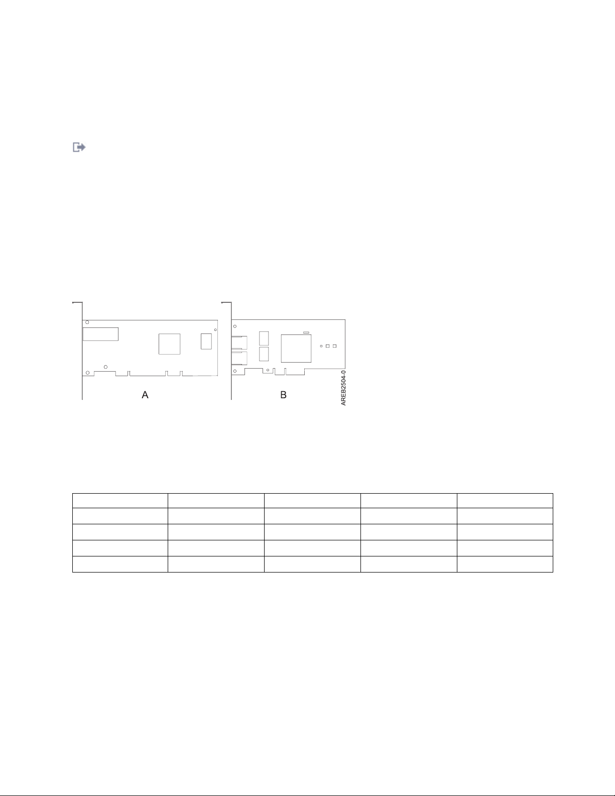
illustration shows an example of a PCI-X adapter (A) next to a PCIe 4x (B) adapter.
Figure 1. PCI-X adapter and PCIe 4x adapter
PCIe adapters and slots come in 4 different sizes: 1x, 4x, 8x, and 16x. Smaller size adapters do fit in larger
slots, but larger size adapters do not fit in smaller slots. The following table shows PCIe slot
compatibility.
Table 3. PCIe slot compatibility
1x slot 4x slot 8x slot 16x slot
1x adapter Supported Supported Supported Supported
4x adapter Not supported Supported Supported Supported
8x adapter Not supported Not supported Supported Supported
16x adapter Not supported Not supported Not supported Supported
To learn more about the PCIe standard, see the IBM Redbooks®technote: Introduction to PCI Express.
Handling static sensitive devices
Electronic boards, adapters, media drives, and disk drives are sensitive to static electricity discharge.
These devices are wrapped in antistatic bags to prevent damage. Learn about taking precautions to
prevent damage to these devices from static electricity discharge.
v Attach a wrist strap to an unpainted metal surface of your hardware to prevent electrostatic discharge
from damaging your hardware.
v When using a wrist strap, follow all electrical safety procedures. A wrist strap is for static control. It
does not increase or decrease your risk of receiving electric shock when using or working on electrical
equipment.
Managing PCI adapters 3
Page 16

v If you do not have a wrist strap, before removing the product from ESD packaging and installing or
replacing hardware, touch an unpainted metal surface of the system for a minimum of 5 seconds.
v Do not remove the device from the antistatic bag until you are ready to install the device in the
system.
v With the device still in its antistatic bag, touch it to the metal frame of the system.
v Grasp cards and boards by the edges. Avoid touching the components and gold-edge connectors on the
adapter.
v If you need to lay the device down while it is out of the antistatic bag, lay it on the antistatic bag.
Before picking it up again, touch the antistatic bag and the metal frame of the system at the same time.
v Handle the devices carefully to prevent permanent damage.
Important partitioning considerations with dual-slot and multi-adapter configurations
Learn about partitioning considerations with dual-slot and multi-adapter configurations.
Logical partitions can own physical I/O resources. Physical I/O resources are assigned to logical
partitions at the slot level. Assigning a slot to a logical partition enables the operating system that runs in
the logical partition to control the functionality of the I/O resource and power for that slot. When the
operating system powers a slot on or off, the physical I/O resource is powered on or off.
In some I/O configurations, the functionality of an adapter or I/O resource depends on two or more
physical slots. For example, if you have a double-wide RAID adapter (FC 2053, 2054, or 2055) that take
up two adjacent adapter slots or two separate RAID adapters paired together, both physical slots must be
assigned to the same logical partition. For example, if you install the FC 2053, 2054, or 2055 adapter in
slot 2, then the adjacent slot 3 cannot be used to install another adapter even though the slot 3 is reported
as empty. It is important to understand the wanted configuration and function being provided before
completing the logical partitioning and activation of the resources involved.
There are two I/O configurations involving adapter pairs:
v Mult-initiator and high availability
v Auxiliary Write Cache
Multi-initiator and high availability
The terms multi-initiator and high availability (HA) refer to connecting multiple adapters (typically two
adapters) to a common set of disk expansion drawers for increasing availability. This configuration is also
referred to as Dual Storage IOA configuration. This type of connection is commonly done in either of the
following configurations:
Note: Some systems have SAS RAID adapters integrated onto the system boards and use a Cache RAID Dual IOA Enablement Card (FC 5662) to enable storage adapter Write Cache and Dual Storage IOA (HA
RAID Mode). For these configurations, installation of the Cache RAID - Dual IOA Enablement Card
places the two integrated adapters into a HA RAID configuration. There are no separate SAS cables
required to connect the two integrated SAS RAID adapters to each other.
HA two-system configuration
An HA two-system configuration provides a high-availability environment for system storage by enabling
two systems or partitions to have access to the same set of disks and disk arrays. This feature is typically
used with the IBMPowerHA®SystemMirror®. The IBMPowerHA SystemMirror software provides a
commercial computing environment that ensures that mission-critical applications can recover quickly
from hardware and software failures. The support for this configuration is operating system dependent.
4 Power Systems: Managing PCI adapters for the IBM Power 710 Express or the IBM Power 730 Express
Page 17

HA single system configuration
An HA single system configuration provides for redundant adapters from a single system to the same set
of disks and disk arrays. This feature is typically referred to as Multi-Path I/O (MPIO). MPIO support is
part of the operating system support and can be used to provide a redundant IBM SAS RAID controller
configuration with RAID protected disks.
Auxiliary write cache adapter
The auxiliary write cache (AWC) adapter provides a duplicate, nonvolatile copy of write cache data of the
RAID controller to which it is connected.
Protection of data is enhanced by having two battery-backed (nonvolatile) copies of write cache, each
stored on separate adapters. If a failure occurs to the write cache portion of the RAID controller, or the
RAID controller itself fails in such a way that the write cache data is not recoverable, the AWC adapter
provides a backup copy of the write cache data to prevent data loss during the recovery of the failed
RAID controller. The cache data is recovered to the new replacement RAID controller and then written
out to disk before resuming normal operations.
The AWC adapter is not a failover device that can keep the system operational by continuing disk
operations when the attached RAID controller fails. The system cannot use the auxiliary copy of the
cache for runtime operations even if only the cache on the RAID controller fails. The AWC adapter does
not support any other device attachment and performs no other tasks than communicating with the
attached RAID controller to receive backup write cache data. The purpose of the AWC adapter is to
minimize the length of an unplanned outage, due to a failure of a RAID controller, by preventing loss of
critical data that might have otherwise required a system reload.
It is important to understand the difference between multi-initiator connections and AWC connections.
Connecting controllers in a multi-initiator environment refers to multiple RAID controllers connected to a
common set of disk enclosures and disks. The AWC controller is not connected to the disks, and it does
not perform device media accesses.
The RAID controller and the AWC adapter each require a PCI bus connection and are required to be in
the same partition. The two adapters are connected by an internal connection. For the planar RAID
enablement and planar auxiliary cache features, the dedicated connection is integrated into the system
planar.
Related tasks:
Serial-attached SCSI cable planning
Learn about how to install the SAS cables to the hard disk drives or solid-state drives.
Related reference:
“PCIe RAID and SSD SAS adapter 3 Gb (FC 2053, FC 2055; CCIN 57CD)” on page 167
Learn about the specifications and operating system requirements for the feature code (FC) 2053 or 2055
adapter.
“PCIe Dual - x4 3 Gb SAS RAID Adapter (FC 5903 and FC 5805; CCIN 574E)” on page 174
Learn about the specifications and operating system requirements for the feature code (FC) 5903 and FC
5805 adapters.
“PCIe2 1.8 GB Cache RAID SAS Tri-port 6 Gb Adapter (FC 5913; CCIN 57B5)” on page 180
Learn about the specifications and operating system requirements for the feature code (FC) 5913 adapters.
“PCIe2 RAID SAS Adapter Dual-port 6Gb (FC ESA1; CCIN 57C4)” on page 184
Learn about the specifications and operating system requirements for the feature code (FC) ESA1
adapters.
“PCIe2 RAID SAS Adapter Dual-port 6-Gb LP (FC ESA2; CCIN 57C4)” on page 186
Learn about the specifications and operating system requirements for the feature code (FC) ESA2
Managing PCI adapters 5
Page 18

adapters.
“PCIe2 3.1GB Cache Integrated SAS RAID Adapter (CCIN 57C3) included in Feature 5888” on page 189
Learn about the specifications and operating system requirements for the PCIe2 3.1GB Cache Integrated
SAS RAID adapter that is integrated with the EXP30 Ultra SSD I/O Drawer (feature code 5888 PCIe
storage enclosure). The adapter reports as PCIe2 3.1GB Cache RAID SAS Enclosure 6Gb x8.
Related information:
Logical partitioning
Information about logical partitioning.
Changing partition profile properties
Information about changing partition profile properties by using the HMC.
Dual IOA Enablement Card (FC 5662)
Information about the specifications for the Dual IOA Enablement Card.
SAS RAID controllers for AIX
Information about usage and maintenance information for the SAS RAID Controller for the AIX.
SAS RAID controllers for IBM i
Information about usage and maintenance information for the SAS RAID Controller for the IBM i.
SAS RAID controllers for Linux
Information about the usage and maintenance information for the SAS RAID Controller for Linux.
PCI adapter information by feature type for the 8231-E2B, 8231-E1C, 8231-E1D, 8231-E2C, 8231-E2D, or 8268-E1D
Find technical information for specific adapters supported on your system. Adapters can be identified by
their feature code (FC) or their custom card identification number (CCIN).
Related tasks:
Installing PCI adapters
Related reference:
IBM Prerequisite website
Parts information
PCI adapter placement
“Backplane daughter cards and RAID enablement cards” on page 2
Find links to topics that cover Backplane daughter cards and RAID enablement cards.
Related information:
Adapters, Devices, and Cable Information for Multiple Bus Systems (SA38-0516)
Information about older adapters that are not covered in Managing PCI adapters, and that were
announced before October 2003.
PCIe LP 4-Port Async EIA-232 Adapter (FC 5277; CCIN 57D2)
Learn about the features, operating system requirements, and installation procedures for the feature code
(FC) 5277 adapters.
Overview
The FC 5277 (PCIe LP 4-Port Async EIA-232 Adapter) is the low-profile version of the FC 5785 (4 Port
Async EIA-232 PCIe adapter), which is a full-height adapter.
6 Power Systems: Managing PCI adapters for the IBM Power 710 Express or the IBM Power 730 Express
Page 19
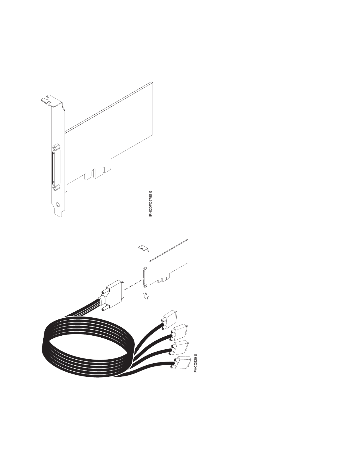
The PCIe LP 4-Port Async EIA-232 Adapter provides connections for four asynchronous EIA-232 devices
using a 4-port DB-9F DTE fan-out cable. Ports are programmable to support EIA-232 protocols at a line
speed of 128 Kbps.
The following figures show the adapter and cable.
Figure 2. Adapter
Figure 3. Cable
Specifications
Item Description
Managing PCI adapters 7
Page 20

FRU number
Adapter: 46K6734
Cable: 46K6735
*
Designed to comply with RoHS requirement.
*
*
I/O bus architecture
PCIe-V1.0a 1x
Busmaster
No
Maximum number
For the maximum adapters supported, see the PCI adapter placement topic collection for your
system.
Adapter size
PCIe 1x, short form factor
Connectors
Adapter: 68-pin SCSI
Cable: 68-pin SCSI to DB 9-pin shell
Wrap plug
42R5143
For details about slot priorities and placement rules, see the PCI adapter placement topic collection for
your system.
Operating system or partition requirements
If you are installing a new feature, ensure that you have the software that is required to support the new
feature and that you determine whether there are any prerequisites for this feature and attaching devices.
To check for the prerequisites, see IBM Prerequisite website (www-912.ibm.com/e_dir/eServerPrereq.nsf).
The adapter is supported on the following versions of the operating system:
v AIX:
– AIX 7.1, or later
– AIX 6.1, or later
– AIX 5L™Version 5.3 with the 5300-07 Technology Level, or later
The AIX device package name is devices.pci.1410a803.rte.
The adapter is supported on the following operating system:
v Linux:
– SUSE Linux Enterprise Server 11, or later
– Red Hat Enterprise Linux version 5.3, or later
v IBM i
– IBM i 7.3, or later
– IBM i 7.2 TR4, or later
– IBM i 7.1 TR11, or later
Preparing for installation
If you are installing your operating system at this time, install your adapter before you install the
operating system. If you are installing only the device driver for this adapter, install your device driver
software before you install the adapter.
8 Power Systems: Managing PCI adapters for the IBM Power 710 Express or the IBM Power 730 Express
Page 21

Installing the AIX device driver software
To install device driver software, follow the steps in “Installing the AIX device driver software” on page
224.
Installing the adapter
For general instructions on how to install a PCI adapter, see the Installing PCI adapters topic. Return here
to verify the adapter installation.
Verifying the adapter installation
To verify that your system unit recognizes the PCI adapter, do the following steps:
1. If necessary, log in as root user.
2. At the command line, type: lsdev -Cs pci
3. Press Enter.
A list of PCI devices is displayed. If the adapter is installed correctly, the status of available for each port
indicates that the adapter is installed and ready to use. If a message indicates that any of the ports are
defined instead of available, shut down your server and verify that the adapter was installed correctly.
Related tasks:
Installing PCI adapters
Related reference:
IBM Prerequisite website
Parts information
PCI adapter placement
“Backplane daughter cards and RAID enablement cards” on page 2
Find links to topics that cover Backplane daughter cards and RAID enablement cards.
PCIe 2-port Async EIA-232 Adapter (FC 5289; CCIN 57D4)
Learn about the specifications and operating system requirements for the feature code (FC) 5289 adapters.
Overview
FC 5289 and 5290 are both the same adapter. FC 5289 is a full-height adapter, and the FC 5290 is a
low-profile adapter. The names of these two adapters are:
v FC 5289: PCIe 2-port Async EIA-232 Adapter
v FC 5290: PCIe LP 2-port Async EIA-232 Adapter (tailstock only)
The FC 5289 and FC 5290 are 2-port EIA-232 asynchronous serial communications PCI Express (PCIe)
adapters that can be installed in the PCIe slots. The adapters are based on the PCIe 1.1 host bus interface.
The parallel port function is not implemented on these adapters.
Each of the two Universal Asynchronous Receiver/Transmitter (UART) channels contain 128 byte
receiver-transmitter, first-in first-out (FIFO), full modem-control signaling, and standard host interrupts. If
either of the two UART interrupts are active, the host can be interrupted through a single PCI interrupt.
The two-port adapter provides RJ45 Ethernet ports, which are connected by DB-9 connectors.
For details about slot priorities and placement rules, see the PCI adapter placement topic collection for
your system.
Managing PCI adapters 9
Page 22

Specifications
Item Description
Adapter FRU number
74Y4084 (Designed to comply with RoHS requirement)
I/O bus architecture
PCIe 1.1
Slot requirement
For the slot priorities, see the PCI adapter placement topic collection for your system.
Cables
Cat 5 unshielded twisted-pair cables
Voltage
3.3 V
Form factor
Short
Maximum number
For the maximum adapters supported, see the PCI adapter placement topic collection for your
system.
Operating system or partition requirements
This adapter is supported for the following versions of the operating systems:
v AIX:
– AIX 7.1 with the 7100-01 Technology Level, or later
– AIX 6.1 with the 6100-07 Technology Level, or later
– AIX 5.3 with the 5300-12 Technology Level, and Service Pack 5, or later
v Linux:
– SUSE Linux Enterprise Server 11 SP1, or later
– SUSE Linux Enterprise Server 10 SP4, or later
– Red Hat Enterprise Linux Version 6.1, or later
– Red Hat Enterprise Linux Version 5.7, or later
– See the Linux Alert site for the support details.
Related tasks:
Installing PCI adapters
Related reference:
IBM Prerequisite website
Parts information
PCI adapter placement
“Backplane daughter cards and RAID enablement cards” on page 2
Find links to topics that cover Backplane daughter cards and RAID enablement cards.
PCIe LP 2-port Async EIA-232 Adapter (FC 5290; CCIN 57D4)
Learn about the specifications and operating system requirements for the feature code (FC) 5290 adapters.
Overview
FC 5289 and 5290 are both the same adapter. FC 5289 is a full-height adapter, and the FC 5290 is a
low-profile adapter.
10 Power Systems: Managing PCI adapters for the IBM Power 710 Express or the IBM Power 730 Express
Page 23

The FC 5289 and FC 5290 are 2-port EIA-232 asynchronous serial communications PCI Express (PCIe)
adapters that can be installed in the PCIe slots. The adapters are based on the PCIe 1.1 host bus interface.
The parallel port function is not implemented on these adapters.
Each of the two universal asynchronous receiver/transmitter (UART) channels contain 128 byte
receiver-transmitter, first-in first-out (FIFO), full modem-control signaling, and standard host interrupts. If
either of the two UART interrupts are active, the host can be interrupted through a single PCI interrupt.
The two-port adapter provides RJ45 Ethernet ports, which are connected by DB-9 connectors.
For details about slot priorities and placement rules, see the PCI adapter placement topic collection for
your system.
Specifications
Item Description
Adapter FRU number
74Y4085 (Designed to comply with RoHS requirement)
I/O bus architecture
PCIe 1.1
Slot requirement
For the slot priorities, see the PCI adapter placement topic collection for your system.
Cables
Cat 5 unshielded twisted-pair cables
Voltage
3.3 V
Form factor
Short
Maximum number
For the maximum adapters supported, see the PCI adapter placement topic collection for your
system.
Operating system or partition requirements
This adapter is supported for the following versions of the operating systems:
v AIX:
– AIX 7.1 with the 7100-01 Technology Level, or later
– AIX 6.1 with the 6100-07 Technology Level, or later
– AIX 5.3 with the 5300-12 Technology Level, and Service Pack 5, or later
v Linux:
– SUSE Linux Enterprise Server 11 SP1, or later
– SUSE Linux Enterprise Server 10 SP4, or later
– Red Hat Enterprise Linux Version 6.1, or later
– Red Hat Enterprise Linux Version 5.7, or later
– For support details, see the Linux Alert website (www14.software.ibm.com/webapp/set2/sas/f/
lopdiags/info/LinuxAlerts.htm)
v IBM i:
– IBM i Version 7.1, or later
If you are installing a new feature, ensure that you have the software that is required to support the new
feature and that you determine whether there are any prerequisites for this feature and attaching devices.
To check for the prerequisites, see IBM Prerequisite website (www-912.ibm.com/e_dir/eServerPrereq.nsf).
Related tasks:
Installing PCI adapters
Managing PCI adapters 11
Page 24
Related reference:
IBM Prerequisite website
Parts information
PCI adapter placement
“Backplane daughter cards and RAID enablement cards” on page 2
Find links to topics that cover Backplane daughter cards and RAID enablement cards.
4-port Async EIA-232 PCIe Adapter (FC 5785; CCIN 57D2)
Learn about the features, operating system requirements, and installation procedures for the feature code
(FC) 5785 adapters.
Overview
The FC 5785 is the is full-height adapter similar to FC 5277 (PCIe LP 4-port Async EIA-232 adapter),
which is the low-profile adapter.
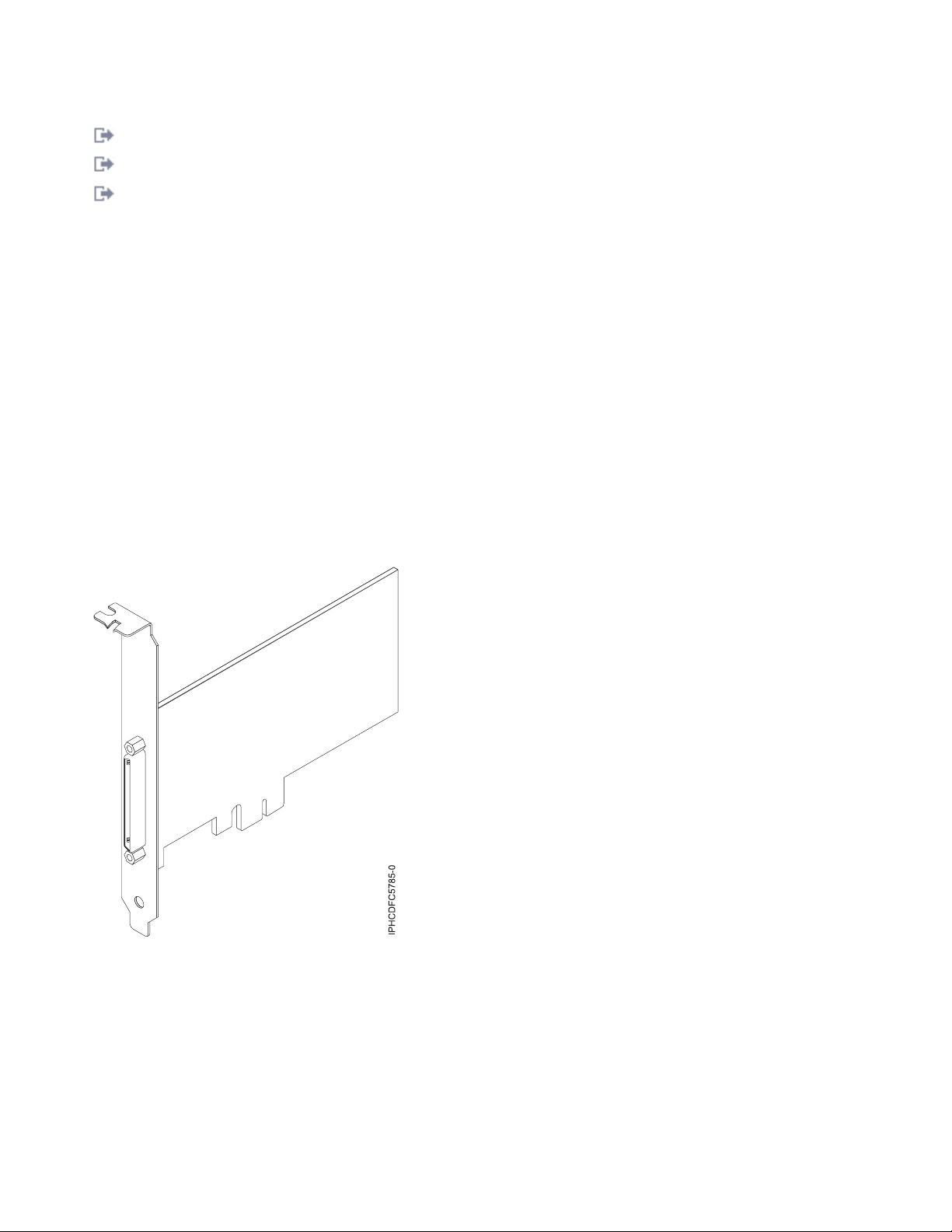
The 4-port Async EIA-232 PCIe Adapter provides connections for four asynchronous EIA-232 devices
using a 4-port DB-9F DTE fan-out cable. Ports are programmable to support EIA-232 protocols at a line
speed of 128 Kbps.
The following figures show the adapter and cable.
Figure 4. Adapter
12 Power Systems: Managing PCI adapters for the IBM Power 710 Express or the IBM Power 730 Express
Page 25
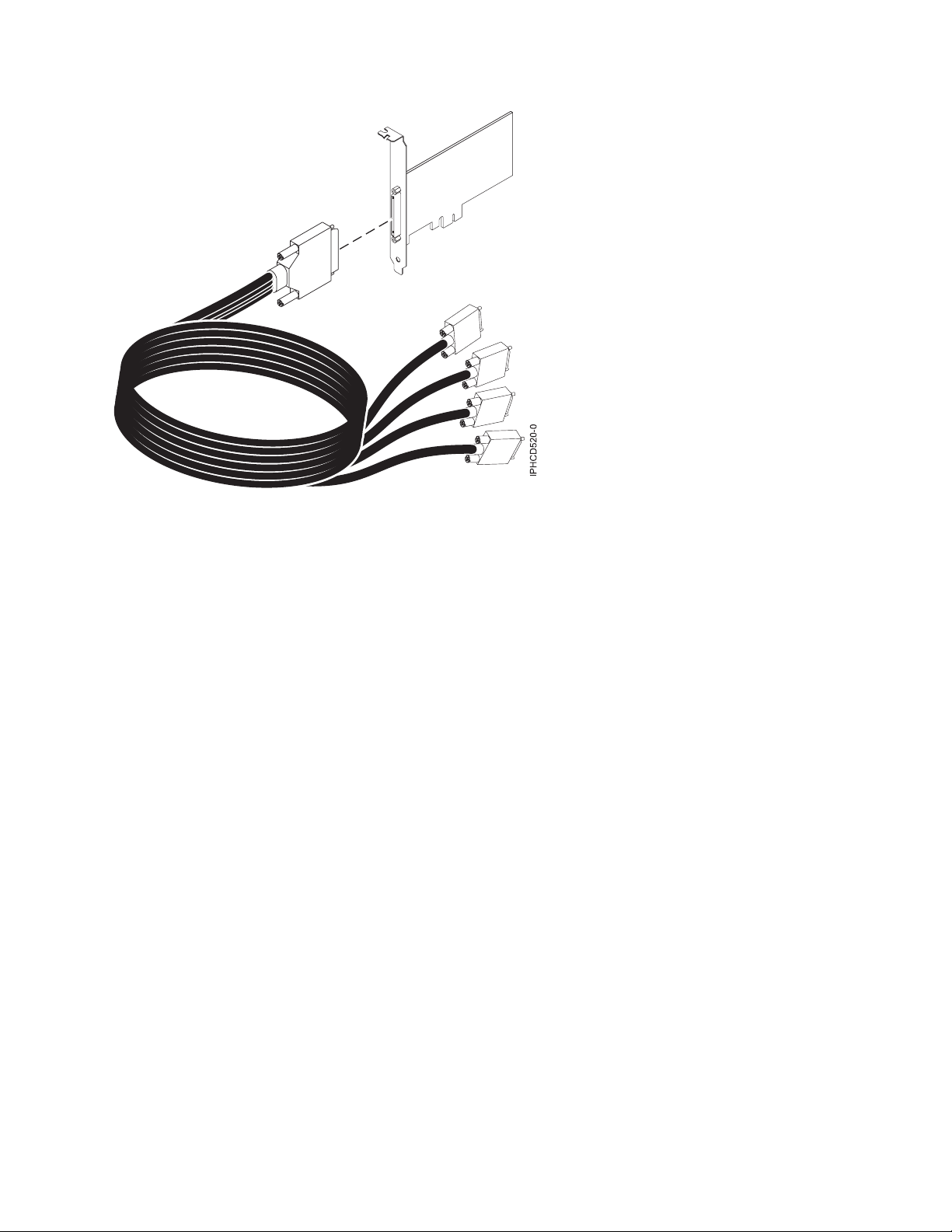
Figure 5. Cable
Specifications
Item Description
FRU number
Adapter: 46K6734
Cable: 46K6735
*
Designed to comply with RoHS requirement.
I/O bus architecture
PCIe-V1.0a 1x
Busmaster
No
Maximum number
For the maximum adapters supported, see the PCI adapter placement topic collection for your
system.
Adapter size
PCIe 1x, short form factor
Connectors
Adapter: 68-pin SCSI
Cable: 68-pin SCSI to DB 9-pin shell
Wrap plug
42R5143
*
*
For details about slot priorities and placement rules, see the PCI adapter placement topic collection for
your system.
Operating system or partition requirements
If you are installing a new feature, ensure that you have the software that is required to support the new
feature and that you determine whether there are any prerequisites for this feature and attaching devices.
To check for the prerequisites, see IBM Prerequisite website (www-912.ibm.com/e_dir/eServerPrereq.nsf).
Managing PCI adapters 13
Page 26

The adapter is supported on the following operating systems:
v AIX:
– AIX 7.1, or later
– AIX 6.1, or later
– AIX 5L Version 5.3 with the 5300-07 Technology Level, or later
The AIX device package name is devices.pci.1410a803.rte.
v Linux:
– SUSE Linux Enterprise Server 11, or later
– Red Hat Enterprise Linux Version 5.3, or later
Preparing for installation
If you are installing your operating system at this time, install your adapter before you install the
operating system. If you are installing only the device driver for this adapter, install your device driver
software before you install the adapter.
Installing the AIX device driver software
To install device driver software, follow the steps in “Installing the AIX device driver software” on page
224.
Installing the adapter
For general instructions on how to install a PCI adapter, see the Installing PCI adapters topic. Return here
to verify the adapter installation.
Verifying the adapter installation
To verify that your system unit recognizes the PCI adapter, do the following steps:
1. If necessary, log in as root user.
2. At the command line, type: lsdev -Cs pci
3. Press Enter.
A list of PCI devices is displayed. If the adapter is installed correctly, the status of available for each port
indicates that the adapter is installed and ready to use. If a message indicates that any of the ports are
defined instead of available, shut down your server and verify that the adapter was installed correctly.
Related tasks:
“Installing the AIX device driver software” on page 224
Learn how to install the AIX device driver software for a PCI adapter.
“Verifying the AIX device driver software” on page 225
Learn how to verify the AIX device driver is installed for a PCI adapter.
Installing PCI adapters
Related reference:
IBM Prerequisite website
Parts information
PCI adapter placement
“Backplane daughter cards and RAID enablement cards” on page 2
Find links to topics that cover Backplane daughter cards and RAID enablement cards.
14 Power Systems: Managing PCI adapters for the IBM Power 710 Express or the IBM Power 730 Express
Page 27
PCIe LP 8 Gb 2-Port Fibre Channel Adapter (FC 5273 and FC EL2N; CCIN 577D)
Learn about the specifications and operating system requirements for the feature codes (FCs) 5273 and
EL2N adapters.
Overview
The PCIe LP 8 Gb 2-Port Fibre Channel Adapter is a high-performance adapter based on the Emulex
LPe12002 PCIe Host Bus Adapter (HBA). The FCs 5273 is a full-height adapter. Each port provides single
initiator capability over a fiber link. The ports have LC type connectors that use shortwave laser optics.
The adapter connects to Fibre Channel switches and direct attached storage devices, operating at link
speeds of 2, 4, and 8 Gbps. The adapter automatically negotiates with the switch to the highest speed that
the switch is capable of. LEDs on each port provide information about the status and link speed of the
port.
N_Port ID Virtualization (NPIV) capability is supported through Virtual I/O Server (VIOS).
The following figure shows the adapter:
Figure 6. 5273 adapter
For details about slot priorities and placement rules, see the PCI adapter placement topic collection for
your system.
Adapter specifications
Item Description
FRU number
10N9824 (Designed to comply with RoHS requirement)
Wrap plug FRU number
12R9314 (Designed to comply with RoHS requirement)
11P3847 (Not designed to comply with RoHS requirement)
Managing PCI adapters 15
Page 28

I/O bus architecture
PCI Express (PCIe) Base and Card Electromechanical (CEM) 2.0
x8 PCIe bus interface
Slot requirement
One available PCIe x8 or x16 slot
Voltage
3.3 V
Form factor
Short, low-profile with standard-size bracket
FC compatibility
2, 4, 8 Gigabit
Cables
Cables are the responsibility of the customer. Use multimode fiber optic cables with shortwave
lasers that adhere to the following specifications:
v OM3: Multimode 50/125 micron fiber, 2000 MHz x km bandwidth
v OM2: Multimode 50/125 micron fiber, 500 MHz x km bandwidth
v OM1: Multimode 62.5/125 micron fiber, 200 MHz x km bandwidth
Because core sizes are different, OM1 cables can only be connected to other OM1 cables. For best
results, OM2 cables should not be connected to OM3 cables. However, if an OM2 cable is
connected to an OM3 cable, the characteristics of the OM2 cable apply to the entire length of the
cables.
The following table shows the supported distances for the three different cable types at the three
different link speeds.
Table 4. Supported distances for cables
Header Cable Type and Distance
Rate OM1 OM2 OM3
2.125 Gbps 0.5 meters to 150 meters
(1.64 feet to 492.12 feet)
4.25 Gbps 0.5 meters to 70 meters
(1.64 feet to 229.65 feet)
8.5 Gbps 0.5 meters to 21 meters
(1.64 feet to 68.89 feet)
0.5 meters to 300 meters
(1.64 feet to 984.25 feet)
0.5 meters to 150 meters
(1.64 feet to 492.12 feet)
0.5 meters to 50 meters
(1.64 feet to 164.04 feet)
0.5 meters to 500 meters
(1.64 feet to 1640.41 feet)
0.5 meters to 380 meters
(1.64 feet to 1246.71 feet)
0.5 meters to 150 meters
(1.64 feet to 492.12 feet)
Maximum number
For the maximum adapters supported, see the PCI adapter placement topic collection for your
system.
Operating system or partition requirements
If you are installing a new feature, ensure that you have the software that is required to support the new
feature and that you determine whether there are any prerequisites for this feature and attaching devices.
To check for the prerequisites, see IBM Prerequisite website (www-912.ibm.com/e_dir/eServerPrereq.nsf).
The adapter is supported on the following versions of the operating systems:
v AIX
– AIX Version 7.1, or later
– AIX Version 6.1, or later
– AIX Version 5.3, or later
v Linux
– Red Hat Enterprise Linux 6.1 for POWER, or later
– SUSE Linux Enterprise Server 11, Service Pack 1, or later (with update package)
16 Power Systems: Managing PCI adapters for the IBM Power 710 Express or the IBM Power 730 Express
Page 29

– See the Linux Alert site for the support details.
v IBM i
– IBM i 7.1, or later.
– IBM i 6.1, or later.
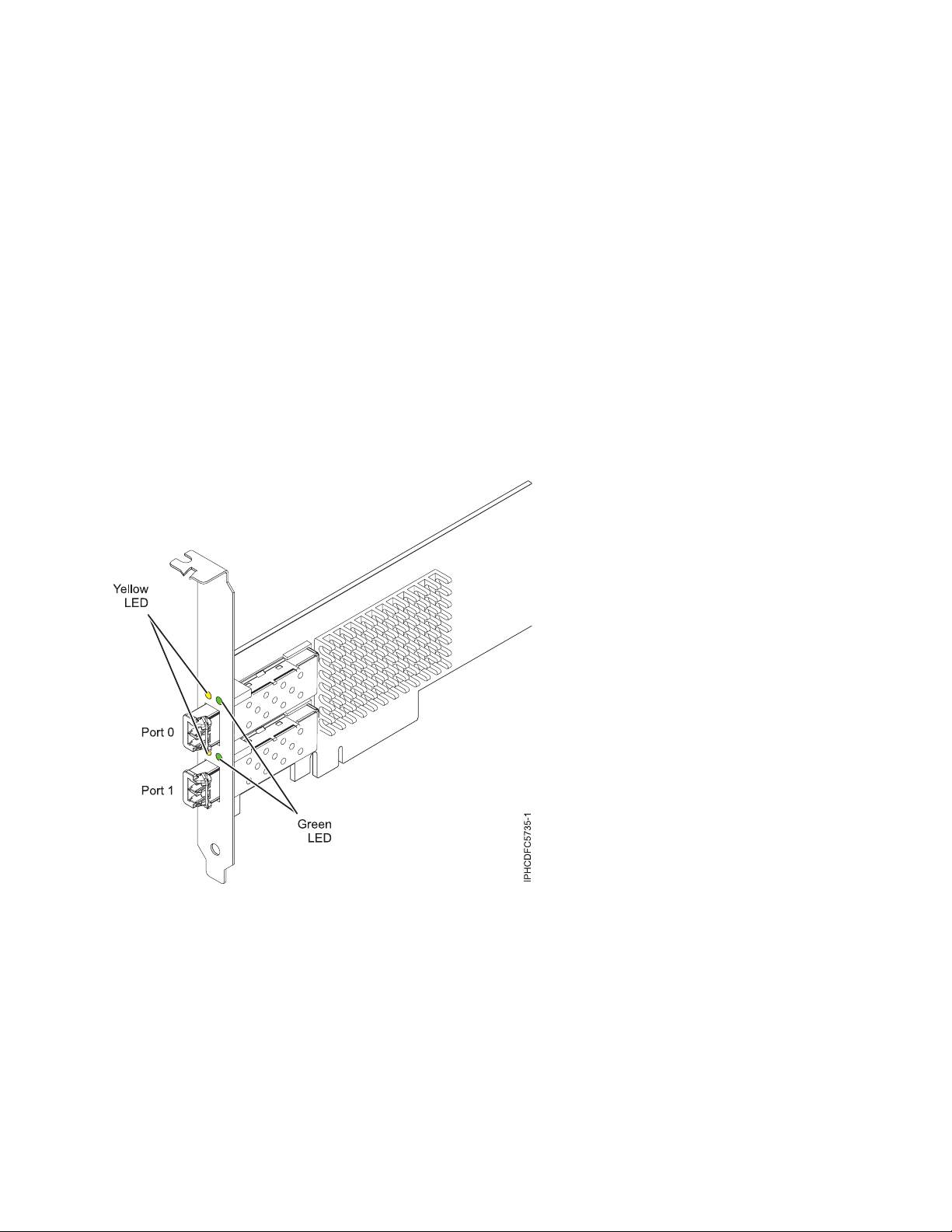
Adapter LED
Green and yellow LEDs can be seen through openings in the mounting bracket of the adapter. Green
indicates firmware operation and yellow signifies port activity. Table 5 summarizes the link rate
conditions. There is a 1-second pause when the LED is off between each group of fast flashes (2, 3, or 4).
Observe the LED sequence for several seconds to be sure that you have correctly identified the state.
Table 5. Normal LED states
Green LED Yellow LED State
Slow flash Off Normal, link inactive or not started
On 2 fast flashes 2 Gbps link rate - normal, link active
On 3 fast flashes 4 Gbps link rate - normal, link active
On 4 fast flashes 8 Gbps link rate - normal, link active
Power-on self test (POST) conditions and results are summarized in Table 6. These states can be used to
identify abnormal states or problems. Follow the action to be taken for each condition.
Table 6. POST conditions and results
Green LED Yellow LED State Action to be taken
Off Off Wake-up failure (dead board) Perform AIX, Linux or IBM i operating system
diagnostics procedure.
Off On POST failure (dead board) Perform AIX, Linux or IBM i operating system
diagnostics procedure.
Off Slow flash Wake-up failure monitor Perform AIX, Linux or IBM i operating system
diagnostics procedure.
Off Fast flash POST failure Perform AIX, Linux or IBM i operating system
diagnostics procedure.
Off Flashing POST processing in progress None
On Off Failure while functioning Perform AIX, Linux or IBM i operating system
diagnostics procedure.
On On Failure while functioning Perform AIX, Linux or IBM i operating system
diagnostics procedure.
Slow flash Slow flash Offline for download None
Slow flash Fast flash Restricted offline mode,
waiting for restart
Slow flash Flashing Restricted offline mode, test
active
None
None
Replacing Fibre Channel adapters by using hot swap
When hot swapping Fibre Channel adapters, be aware that device-related software for the storage devices
might have additional devices (for example, the disk array router (dar) device associated with the fiber
array storage technology (FAStT) or DS4800) that need to be removed. See the specific storage device
documentation for information about how to remove these additional devices.
Managing PCI adapters 17
Page 30

The new adapter has a unique worldwide port name (WWPN). Check the zoning and logical unit
number (LUN) assignments to ensure that the new adapter functions as expected.
Related tasks:
Installing PCI adapters
Related reference:
IBM Prerequisite website
Parts information
PCI adapter placement
“Backplane daughter cards and RAID enablement cards” on page 2
Find links to topics that cover Backplane daughter cards and RAID enablement cards.
4 Gigabit PCI Express Dual Port Fibre Channel Adapter (FC 5276; CCIN
5774)
Learn about the specifications and operating system requirements for the feature code (FC) 5776 adapter.
Overview
The FC 5276 (4 Gigabit PCIe Dual Port Fibre Channel Adapter) is the low-profile adapter same as the FC
5774, which is the regular height adapter. The names of the two adapters are:
v FC 5276: 4 Gigabit PCIe Dual Port Fibre Channel Adapter
v FC 5774: 4 Gigabit PCIe Dual Port Fibre Channel Adapter
The 4 Gigabit PCIe Dual Port Fibre Channel Adapter is a 64 bit, low-profile, short form factor x4, PCIe
adapter with an LC-type external fiber connector that provides single initiator capability over an optical
fiber link or loop. The adapter automatically negotiates the highest data rate between the adapter and an
attaching device at 1 Gbps, 2 Gbps, or 4 Gbps of which the device or switch is capable. Distances
between the adapter and an attaching device or switch can reach up to 500 meters running at 1 Gbps
data rate, up to 300 meters running at 2 Gbps data rate, and up to 150 meters running at 4 Gbps data
rate. When used with IBM Fibre Channel storage switches supporting long-wave optics, the adapter can
reach distances of up to 10 kilometers running at either 1 Gbps, 2 Gbps, or 4 Gbps data rates.
The adapter can be used to attach devices either directly, or with Fibre Channel switches. If you are
attaching a device or switch with an SC type fiber connector, you must use an LC-SC 50 micron fiber
converter cable (FC 2456) or an LC-SC 62.5 micron fiber converter cable (FC 2459).
The adapter has the following features:
v Compliant with the PCIe Base and Card Electromechanical (CEM) 1.0a specifications:
– x1 and x4 lane link interface at 2.5 Gbit/s (auto-negotiated with system)
– Supports VC0 (1 Virtual Channel) and TC0 (1 Traffic Class)
– Configuration and IO Memory read/write, completion, message
– Support for 64-bit addressing
– ECC error protection
– Link CRC on all PCIe packets and message information
– Large payload size: 2048 bytes for read and write
– Large read request size: 4096 bytes
v Compatible with 1, 2, and 4 Gb Fibre Channel interface:
– Auto-negotiate between 1 Gb, 2 Gb or 4 Gb link attachments
– Support for all Fibre Channel topologies: point-to-point, arbitrated loop, and fabric
18 Power Systems: Managing PCI adapters for the IBM Power 710 Express or the IBM Power 730 Express
Page 31

– Support for Fibre Channel class 2 and 3
– Maximum Fibre Channel throughput achieved by using full duplex hardware support
v End-to-end data path parity and CRC protection, including internal data path RAMs
v Architectural support for multiple upper layer protocols
v Internal high-speed SRAM memory
v ECC protection of local memory, includes single-bit correction and double-bit protection
v Embedded shortwave optical connection with diagnostics capability
v Onboard Context Management by firmware (per port):
– Up to 510 FC Port Logins
– Up to 2047 concurrent Exchanges
– I/O multiplexing down to the FC Frame level
v Data buffers capable of supporting 64+ buffer-to-buffer (BB) credits per port for shortwave applications
v Link management and recovery handled by firmware
v Onboard diagnostic capability accessible by optional connection
v Parts and construction compliant with the European Union Directive of Restriction of Hazardous
Substances (RoHS)
v Performance up to 4.25 Gbps full duplex
The following figure shows the adapter.
Figure 7. 5276 adapter
Specifications
Item Description
Adapter FRU number
10N7255
*
Designed to comply with RoHS requirement
Wrap plug FRU number
11P3847
*
Managing PCI adapters 19
Page 32

I/O bus architecture
PCIe Base and CEM 1.0a
x4 PCIe bus interface
Slot requirement
One available PCIe x4, x8, or x16 slot
Voltage
3.3V
Form factor
Short, low-profile
FC compatibility
1, 2, 4 gigabit
Cables
50/125 micron fiber (500 MHz*km bandwidth cable)
v 1.0625 Gbps 0.5 – 500 m
v 2.125 Gbps 0.5 – 300 m
v 4.25 Gbps 0.5 – 150 m
62.5/125 micron fiber (200 MHz*km bandwidth cable)
v 1.0625 Gbps 0.5 – 300 m
v 2.125 Gbps 0.5 – 150 m
v 4.25 Gbps 0.5 – 70 m
Maximum number
For the maximum adapters supported, see the PCI adapter placement topic collection for your
system.
For details about slot priorities and placement rules, see the PCI adapter placement topic collection for
your system.
Operating system or partition requirements
If you are installing a new feature, ensure that you have the software that is required to support the new
feature and that you determine whether there are any prerequisites for this feature and attaching devices.
To check for the prerequisites, see IBM Prerequisite website (www-912.ibm.com/e_dir/eServerPrereq.nsf).
The adapter is supported on the following versions of the operating systems:
v AIX
– AIX Version 7.1, or later.
– AIX Version 6.1, or later.
– AIX Version 5.3, or later.
v Linux
– Red Hat Enterprise Linux 5.6 for POWER, or later.
– Novel SUSE Linux Enterprise Server 11 Service Pack 1, or later.
v IBM i
– IBM i 7.1, or later
– IBM i 6.1, or later
Adapter LED states
Green and yellow LEDs can be seen through openings in the mounting bracket of the adapter. Green
indicates firmware operation and yellow signifies port activity. Table 7 on page 21 summarizes normal
LED states. There is a 1 Hz pause when the LED is off between each group of fast flashes (1, 2 or 3).
Observe the LED sequence for several seconds to ensure that you correctly identify the state.
20 Power Systems: Managing PCI adapters for the IBM Power 710 Express or the IBM Power 730 Express
Page 33

Table 7. Normal LED states
Green LED Yellow LED State
On 1 fast flash 1 Gbps link rate - normal, link active
On 2 fast flashes 2 Gbps link rate - normal, link active
On 3 fast flashes 4 Gbps link rate - normal, link active
Power-On Self Test (POST) conditions and results are summarized in Table 8. These states can be used to
identify abnormal states or problems.
Table 8. POST conditions and results
Green LED Yellow LED State
Off Off Wake-up failure (dead board)
Off On POST failure (dead board)
Off Slow flash Wake-up failure monitor
Off Fast flash Failure in post
Off Flashing Post processing in progress
On Off Failure while functioning
On On Failure while functioning
Slow flash Off Normal, link down
Slow flash On Not defined
Slow flash Slow flash Offline for download
Slow flash Fast flash Restricted offline mode, waiting for
restart
Slow flash Flashing Restricted offline mode, test active
Fast flash Off Debug monitor in restricted mode
Fast flash On Not defined
Fast flash Slow flash Debug monitor in test fixture mode
Fast flash Fast flash Debug monitor in remote debug
mode
Fast flash Flashing Not defined
Device ID jumper
The default setting for the two device ID jumpers labeled P0_JX. and P1_JX is to set the jumpers on pins
1 and 2 as shown in Figure 8 on page 22. Do not change the jumper settings for a standard installation.
Managing PCI adapters 21
Page 34

Figure 8. Device ID jumper
Replacing hot swap HBAs
Fiber Channel host bus adapters (HBAs) connected to a fiber array storage technology (FAStT) or
DS4000®storage subsystem have a child device called a disk array router (dar). You must unconfigure the
disk array router before you can hot swap an HBA that is connected to a FAStT or DS4000 storage
subsystem. For instructions, see Replacing hot swap HBAs in the IBM System Storage®DS4000 Storage
Manager Version 9, Installation and Support Guide for AIX, HP-UX, Solaris, and Linux on Power Systems
Servers, order number GC26-7848.
Related tasks:
Installing PCI adapters
Related reference:
IBM Prerequisite website
Parts information
PCI adapter placement
“Backplane daughter cards and RAID enablement cards” on page 2
Find links to topics that cover Backplane daughter cards and RAID enablement cards.
™
PCIe3 LP 16 Gb 2-port Fibre Channel Adapter (FC EN0B; CCIN 577F)
Learn about the specifications and operating system requirements for the feature code (FC) EN0B adapter.
Overview
The PCIe3 LP 16 Gb 2-port Fibre Channel Adapter is a PCI Express (PCIe) generation 3 (Gen3) x8, short
form-factor, low-profile adapter. This adapter has a little connector-type (LC) external fiber connector that
provides single initiator capability over an optical fiber link. The adapter automatically negotiates the
highest data rate between the adapter and an attaching device at a link speed of 16 Gbps, 8 Gbps, or 4
Gbps. The adapter supports a maximum link speed of 16 Gbps at both ports. Distances between the
adapter and an attaching device or switch can reach up to 380 m running at a 4 Gbps data rate, up to 150
22 Power Systems: Managing PCI adapters for the IBM Power 710 Express or the IBM Power 730 Express
Page 35

m running at an 8 Gbps data rate, and up to 100 m running at a 16 Gbps data rate. When used with IBM
Fibre Channel storage switches supporting long-wave optics, the adapter can reach distances of up to 10
km running at 4 Gbps, 8 Gbps, or 16 Gbps data rates.
The adapter has the following features:
v This adapter has parts and construction compliant with the European Union Directive of Restriction of
Hazardous Substances (RoHS)
v The adapter is compliant with the PCIe base and Card Electromechanical (CEM) 3.0 specifications with
the following characteristics:
– Provides an x8 lane link interface at 14.025 Gbps, 8.5 Gbps, or 4.25 Gbps (automatic negotiation with
system)
– Provides support for one Virtual Channel (VC0) and one Traffic Class (TC0)
– Provides configuration and I/O memory read and write, completion, and messaging capabilities
– Provides support for 64-bit addressing
– Provides error correction code (ECC) and error protection functions
– Provides link cyclic redundancy check (CRC) on all PCIe packets and message information
– Provides a large payload size of 2048 bytes for read and write functions
– Provides a large read request size of 4096 bytes
v The adapter is compatible with 4, 8, and 16 Gb Fibre Channel interface with the following
characteristics:
– Provides for automatic negotiation between 4 Gb, 8 Gb, or 16 Gb link attachments
– Provides support for the following Fibre Channel topologies: point-to-point (16Gb only) and fabric
– Provides support for Fibre Channel class 3
– Provides a maximum Fibre Channel throughput that is achieved by using full duplex hardware
support
v The adapter provides an end-to-end data path parity and CRC protection, including internal data path
random-access memory (RAM)
v Provides architectural support for multiple upper layer protocols
v Provides comprehensive virtualization capabilities with support for N_Port ID Virtualization (NPIV)
and virtual fabric (VF)
v Provides support for message signaled interrupts extended (MSI-X)
v Provides support for 255 VFs and 1024 MSi-X
v Provides an internal, high-speed static random-access memory (SRAM) memory
v Provides ECC protection of local memory that includes single-bit correction and double-bit protection
v Provides an embedded shortwave optical connection with diagnostics capability
v Provides support for an on-board context management by firmware:
– Up to 8192 FC port logins
– I/O multiplexing down to the Fibre Channel frame level
v Provides data buffers capable of supporting 64+ buffer-to-buffer (BB) credits per port for shortwave
applications
v Provides link management and recovery that is handled by firmware
v Provides on-board diagnostic capability accessible by an optional connection
v Provides a performance up to 16 Gbps full duplex
The following figure shows the adapter.
Managing PCI adapters 23
Page 36

Figure 9. EN0B adapter
Specifications
Item Description
Adapter FRU number
74Y2221 (Designed to comply with RoHS requirement)
Wrap plug FRU number
12R9314
I/O bus architecture
PCIe base and CEM 3.0, x8 PCIe bus interface
Slot requirement
One available PCIe x8 or x16 slot
Voltage
3.3 V, 12 V
Form factor
Short, low-profile
FC compatibility
4, 8, 16 Gb
Cables
Cables are the responsibility of the customer. Use multimode fiber optic cables with shortwave
lasers that adhere to the following specifications:
v OM3: Multimode 50/125 micron fiber, 2000 MHz x km bandwidth
v OM2: Multimode 50/125 micron fiber, 500 MHz x km bandwidth
v OM1: Multimode 62.5/125 micron fiber, 200 MHz x km bandwidth
Because core sizes are different, OM1 cables can only be connected to other OM1 cables. For best
results, OM2 cables must not be connected to OM3 cables. However, if an OM2 cable is connected
to an OM3 cable, the characteristics of the OM2 cable apply to the entire length of the cables.
The following table shows the supported distances for the different cable types at the different
link speeds.
24 Power Systems: Managing PCI adapters for the IBM Power 710 Express or the IBM Power 730 Express
Page 37

Table 9. Supported distances for cables
Header Cable type and distance
Rate OM1 OM2 OM3
4.25 Gbps 0.5 - 70 m (1.64 - 229.65 ft) 0.5 - 150 m (1.64 - 492.12 ft) 0.5 - 380 m (1.64 - 1246.71
ft)
8.5 Gbps 0.5 - 21 m (1.64 - 68.89 ft) 0.5 - 50 m (1.64 - 164.04 ft) 0.5 - 150 m (1.64 - 492.12 ft)
14.025 Gbps 0.5 - 15 m (1.64 - 49.21 ft) 0.5 - 35 m (1.64 - 114.82 ft) 0.5 - 100 m (1.64 - 328.08 ft)
Maximum number
For the maximum adapters supported, see the PCI adapter placement topic collection for your
system.
Operating system or partition requirements
If you are installing a new feature, ensure that you have the software that is required to support the new
feature and that you determine whether there are any prerequisites for this feature and attaching devices.
To check for the prerequisites, see IBM Prerequisite website (www-912.ibm.com/e_dir/eServerPrereq.nsf).
The adapter is supported on the following versions of the operating systems:
v AIX
– AIX 7.1, or later
– AIX 6.1, or later
v Linux
– Red Hat Enterprise Linux
– SUSE Linux Enterprise Server
– For support details, see the Linux Alert website (www14.software.ibm.com/webapp/set2/sas/f/
lopdiags/info/LinuxAlerts.htm)
v IBM i
– IBM i 7.1, or later
– IBM i 6.1, or later
Adapter LED states
Green and yellow LEDs can be seen through openings in the mounting bracket of the adapter. Green
indicates firmware operation, and yellow signifies port activity. Table 10 summarizes normal LED states.
A 1 Hz pause occurs when the LED is off between each group of fast flashes (2, 3 or 4). Observe the LED
sequence for several seconds to ensure that you correctly identify the state.
Table 10. Normal LED states
Green LED Yellow LED State
On 2 fast flashes 4 Gbps link rate: normal, link active
On 3 fast flashes 8 Gbps link rate: normal, link active
On 4 fast flashes 16 Gbps link rate: normal, link active
Power-on-self-test (POST) conditions and results are summarized in Table 11 on page 26. These states can
be used to identify abnormal states or problems.
Managing PCI adapters 25
Page 38

Table 11. POST conditions and results
Green LED Yellow LED State
Off Off Wake-up failure of the adapter board
Off On POST failure of the adapter board
Off Slow flash Wake-up failure monitor
Off Fast flash Failure in post
Off Flashing Postprocessing in progress
On Off Failure while functioning
On On Failure while functioning
Slow flash Off Normal, link down
Slow flash On Not defined
Slow flash Slow flash Offline for download
Slow flash Fast flash Restricted offline mode, waiting for
restart
Slow flash Flashing Restricted offline mode, test active
Fast flash Off Debug monitor in restricted mode
Fast flash On Not defined
Fast flash Slow flash Debug monitor in test fixture mode
Fast flash Fast flash Debug monitor in remote debug
mode
Fast flash Flashing Not defined
Related tasks:
Installing PCI adapters
Related reference:
IBM Prerequisite website
Parts information
PCI adapter placement
“Backplane daughter cards and RAID enablement cards” on page 2
Find links to topics that cover Backplane daughter cards and RAID enablement cards.
8 Gigabit PCI Express Dual Port Fibre Channel Adapter (FC 5735; CCIN 577D)
Learn about the specifications and operating system requirements for the feature code (FC) 5735 adapter.
Overview
The 8 Gigabit PCI Express Dual Port Fibre Channel Adapter is a high-performance adapter based on the
Emulex LPe12002 PCIe Host Bus Adapter (HBA). Each port provides single initiator capability over a
fibre link. The ports have LC type connectors and utilize shortwave laser optics. The adapter connects to
fibre channel switches and operates at link speeds of 2, 4, and 8 Gbps. The adapter automatically
negotiates with the switch to the highest speed of which the switch is capable. LEDs on each port
provide information on the status and link speed of the port.
The following figure shows the adapter:
26 Power Systems: Managing PCI adapters for the IBM Power 710 Express or the IBM Power 730 Express
Page 39

Figure 10. 5735 adapter
For details about slot priorities and placement rules, see the PCI adapter placement topic collection for
your system.
Adapter specifications
Item Description
FRU number
10N9824 (Designed to comply with RoHS requirement)
Wrap plug FRU number
12R9314 (Designed to comply with RoHS requirement)
11P3847 (Not designed to comply with RoHS requirement)
I/O bus architecture
PCI Express (PCIe) Base and Card Electromechanical (CEM) 2.0
x8 PCIe bus interface
Slot requirement
One available PCIe x8 or x16 slot
Voltage
3.3 V
Form factor
Short, low-profile with standard size bracket
FC compatibility
2, 4, 8 Gigabit
Cables
Cables are the responsibility of the customer. Use multimode fibre optic cables with short-wave
lasers that adhere to the following specifications:
v OM3: Multimode 50/125 micron fibre, 2000 MHz x km bandwidth
v OM2: Multimode 50/125 micron fibre, 500 MHz x km bandwidth
v OM1: Multimode 62.5/125 micron fibre, 200 MHz x km bandwidth
Managing PCI adapters 27
Page 40

Because core sizes are different, OM1 cables can only be connected to other OM1 cables. For best
results, OM2 cables should not be connected to OM3 cables. However, if an OM2 cable is
connected to an OM3 cable, the characteristics of the OM2 cable apply to the entire length of the
cables.
The following table shows the supported distances for the three different cable types at the three
different link speeds.
Table 12. Supported cable distances by link speed
Cable type 2.125 Gbps 4.25 Gbps 8.5 Gbps
OM3 0.5 m - 500 m 0.5 m - 380 m 0.5 m - 150 m
OM2 0.5 m - 300 m 0.5 m -150 m 0.5 m - 50 m
OM1 0.5 m - 150 m 0.5 m - 70 m 0.5 m - 21 m
Maximum number
For the maximum adapters supported, see the PCI adapter placement topic collection for your
system.
Operating system or partition requirements
If you are installing a new feature, ensure that you have the software that is required to support the new
feature and that you determine whether there are any prerequisites for this feature and attaching devices.
To check for the prerequisites, see IBM Prerequisite website (www-912.ibm.com/e_dir/eServerPrereq.nsf).
The adapter is supported on the following versions of the operating systems:
v AIX
– AIX Version 7.1, or later
– AIX Version 6.1, or later
– AIX Version 5.3, or later
v Linux
– Red Hat Enterprise Linux 6.1 for POWER, or later
– SUSE Linux Enterprise Server 11, Service Pack 1, or later (with update package)
– For support details, see the Linux Alert website (www14.software.ibm.com/webapp/set2/sas/f/
lopdiags/info/LinuxAlerts.htm)
v IBM i
– IBM i 7.1, or later.
– IBM i 6.1, or later.
Adapter LED
Green and yellow LEDs can be seen through openings in the adapter mounting bracket. Green indicates
firmware operation and yellow signifies port activity. Table 13 summarizes the link rate conditions. There
is a 1-second pause when the LED is off between each group of fast flashes (2, 3, or 4). Observe the LED
sequence for several seconds to be sure that you have correctly identified the state.
Table 13. Normal LED states
Green LED Yellow LED State
Slow flash Off Normal, link inactive or not started
On 2 fast flashes 2 Gbps link rate - normal, link active
On 3 fast flashes 4 Gbps link rate - normal, link active
On 4 fast flashes 8 Gbps link rate - normal, link active
28 Power Systems: Managing PCI adapters for the IBM Power 710 Express or the IBM Power 730 Express
Page 41

Power-on self test (POST) conditions and results are summarized in Table 14. These states can be used to
identify abnormal states or problems. Follow the action to be taken for each condition.
Table 14. POST conditions and results
Green LED Yellow LED State Action to be taken
Off Off Wake-up failure (dead board) Perform AIX, Linuxor IBM i operating system
diagnostics.
Off On POST failure (dead board) Perform AIX, Linuxor IBM i operating system
diagnostics.
Off Slow blink Wake-up failure monitor Perform AIX, Linuxor IBM i operating system
diagnostics.
Off Fast blink POST failure Perform AIX, Linuxor IBM i operating system
diagnostics.
Off Flashing POST processing in progress None
On Off Failure while functioning Perform AIX, Linuxor IBM i operating system
diagnostics.
On On Failure while functioning Perform AIX, Linuxor IBM i operating system
diagnostics.
Slow blink Slow blink Offline for download None
Slow blink Fast blink Restricted offline mode,
waiting for restart
Slow blink Flashing Restricted offline mode, test
active
None
None
Replacing Fibre Channel adapters using hot swap
When hot swapping fibre channel adapters, be aware that device-related software for the storage devices
might have additional devices (for example, the dar device associated with the FAStT or DS4800) that
need to be removed. Refer to specific storage device documentation for information about how to remove
these additional devices.
The new adapter has a unique worldwide port name (WWPN). Check the zoning and LUN assignments
to ensure that the new adapter will function as expected.
Related tasks:
Installing PCI adapters
Related reference:
IBM Prerequisite website
Parts information
PCI adapter placement
“Backplane daughter cards and RAID enablement cards” on page 2
Find links to topics that cover Backplane daughter cards and RAID enablement cards.
4 Gigabit PCI Express Single Port Fibre Channel Adapter (FC 5773; CCIN 5773)
Learn about the specifications and operating system requirements for the feature code (FC) 5773 adapter.
Managing PCI adapters 29
Page 42

Overview
The 4 Gigabit PCI Express Single Port Fibre Channel adapter is a 64 bit, short form factor x4, PCIe
adapter with an LC-type external fiber connector that provides single initiator capability over an optical
fiber link or loop. The adapter automatically negotiates the highest data rate between the adapter and an
attaching device at 1 Gbps, 2 Gbps, or 4 Gbps of which the device or switch is capable of. Distances
between the adapter and an attaching device or switch can reach up to 500 meters running at 1 Gbps
data rate, up to 300 meters running at 2 Gbps data rate, and up to 150 meters running at 4 Gbps data
rate. When used with IBM Fibre Channel storage switches that support longwave optics, the adapter can
reach distances of up to 10 kilometers running at either 1 Gbps, 2 Gbps, or 4 Gbps data rates.
The adapter can be used to attach devices either directly, or with Fibre Channel switches. If you are
attaching a device or switch with an SC type fiber connector, you must use an LC-SC 50 micron fiber
converter cable (FC 2456) or an LC-SC 62.5 micron fiber converter cable (FC 2459).
The adapter has the following features:
v Compliant with the PCIe Base and Card Electromechanical (CEM) 1.0a specifications:
– x1 and x4 lane link interface at 2.5 Gbit/s (auto-negotiated with system)
– Supports VC0 (1 Virtual Channel) and TC0 (1 Traffic Class)
– Configuration and IO Memory read/write, completion, message
– Support for 64-bit addressing
– ECC error protection
– Link CRC on all PCIe packets and message information
– Large payload size: 2048 bytes for read and write
– Large read request size: 4096 bytes
v Compatible with 1, 2, and 4 Gb Fibre Channel interface:
– Auto-negotiate between 1 Gb, 2 Gb or 4 Gb link attachments
– Support for all Fibre Channel topologies: point-to-point, arbitrated loop, and fabric
– Support for Fibre Channel class 2 and 3
– Maximum Fibre Channel throughput achieved by using full duplex hardware support
v End-to-end data path parity and CRC protection, including internal data path RAMs
v Architectural support for multiple upper layer protocols
v Internal high-speed SRAM memory
v ECC protection of local memory, includes single-bit correction and double-bit protection
v Embedded shortwave optical connection with diagnostics capability
v Onboard Context Management by firmware (per port):
– Up to 510 FC Port Logins
– Up to 2047 concurrent Exchanges
– I/O multiplexing down to the FC Frame level
v Data buffers capable of supporting 64+ buffer-to-buffer (BB) credits per port for shortwave applications
v Link management and recovery handled by firmware
v Onboard diagnostic capability accessible by optional connection
v Parts and construction compliant with the European Union Directive of Restriction of Hazardous
Substances (RoHS)
v Performance up to 4.25 Gbps full duplex
The following figure shows the adapter.
30 Power Systems: Managing PCI adapters for the IBM Power 710 Express or the IBM Power 730 Express
Page 43

Figure 11. 5773 adapter
Adapter specifications
Item Description
FRU number
10N7249
*
Designed to comply with RoHS requirement.
Wrap plug FRU number
12R9314 (for Fibre LC connector)
Note: The wrap plug is included with the card, and can also be bought from IBM.
I/O bus architecture
PCI Express (PCIe) Base and CEM 1.0a
x4 PCIe bus interface
Slot requirement
One available PCIe x4, x8, or x16 slot
Voltage
3.3 V
Form factor
Short, low-profile
FC compatibility
1, 2, 4 gigabit
Cables
*
50/125 micron fiber (500 MHz*km bandwidth cable)
v 1.0625 Gbps 0.5 – 500 m
v 2.125 Gbps 0.5 – 300 m
v 4.25 Gbps 0.5 – 150 m
62.5/125 micron fiber (200 MHz*km bandwidth cable)
v 1.0625 Gbps 0.5 – 300 m
v 2.125 Gbps 0.5 – 150 m
v 4.25 Gbps 0.5 – 70 m
Managing PCI adapters 31
Page 44

Maximum number
For the maximum adapters supported, see the PCI adapter placement topic collection for your
system.
For details about slot priorities and placement rules, see the PCI adapter placement topic collection for
your system.
Operating system or partition requirements
The adapter is supported under the following versions of the operating systems:
v AIX
– AIX 5.3, or later
v Linux
– Red Hat Enterprise Linux version 4
– Red Hat Enterprise Linux version 5
– SUSE Linux Enterprise Server 9, Service Pack 4, or later
– SUSE Linux Enterprise Server 10, Service Pack 1, or later
Note: If you are installing a new feature, ensure that you have the software that is required to support
the new feature and that you determine whether there are any prerequisites. To check for the
prerequisites, see IBM Prerequisite website (www-912.ibm.com/e_dir/eServerPrereq.nsf).
Adapter LED states
Green and yellow LEDs can be seen through openings in the mounting bracket of the adapter. Green
indicates firmware operation and yellow signifies port activity. Table 15 summarizes normal LED states.
There is a 1 Hz pause when the LED is off between each group of fast flashes (1, 2 or 3). Observe the
LED sequence for several seconds to ensure that you correctly identify the state.
Table 15. Normal LED states
Green LED Yellow LED State
On 1 fast flash 1 Gbps link rate - normal, link active
On 2 fast flashes 2 Gbps link rate - normal, link active
On 3 fast flashes 4 Gbps link rate - normal, link active
Power-On Self Test (POST) conditions and results are summarized in Table 16. These states can be used to
identify abnormal states or problems.
Table 16. POST conditions and results
Green LED Yellow LED State
Off Off Wake-up failure (dead board)
Off On POST failure (dead board)
Off Slow flash Wake-up failure monitor
Off Fast flash Failure in post
Off Flashing Post processing in progress
On Off Failure while functioning
On On Failure while functioning
Slow flash Off Normal, link down
Slow flash On Not defined
32 Power Systems: Managing PCI adapters for the IBM Power 710 Express or the IBM Power 730 Express
Page 45

Table 16. POST conditions and results (continued)
Green LED Yellow LED State
Slow flash Slow flash Offline for download
Slow flash Fast flash Restricted offline mode, waiting for
restart
Slow flash Flashing Restricted offline mode, test active
Fast flash Off Debug monitor in restricted mode
Fast flash On Not defined
Fast flash Slow flash Debug monitor in test fixture mode
Fast flash Fast flash Debug monitor in remote debug
mode
Fast flash Flashing Not defined
Device ID jumper
The default setting for the device ID jumper labeled P0_JX is to set the jumper on pins 1 and 2 as shown
in Figure 12. Do not change the jumper settings for a standard installation.
Figure 12. Device ID jumper
Replacing hot swap HBAs
Fiber Channel host bus adapters (HBAs) connected to a fiber array storage technology (FAStT) or DS4000
storage subsystem have a child device called a disk array router (dar). You must unconfigure the disk
array router before you can hot swap an HBA that is connected to a FAStT or DS4000 storage subsystem.
For instructions, see Replacing hot swap HBAs in the IBM System Storage DS4000 Storage Manager Version 9,
Installation and Support Guide for AIX, HP-UX, Solaris, and Linux on Power Systems Servers, order number
GC26-7848.
Related tasks:
Managing PCI adapters 33
Page 46

Installing PCI adapters
Related reference:
IBM Prerequisite website
Parts information
PCI adapter placement
“Backplane daughter cards and RAID enablement cards” on page 2
Find links to topics that cover Backplane daughter cards and RAID enablement cards.
4 Gigabit PCI Express Dual Port Fibre Channel Adapter (FC 5774; CCIN
5774)
Learn about the specifications and operating system requirements for the feature code (FC) 5774 adapter.
Overview
The 4 Gigabit PCI Express Dual Port Fibre Channel Adapter is a 64 bit, short form factor x4, PCIe adapter
with an LC-type external fiber connector that provides single initiator capability over an optical fiber link
or loop. The adapter automatically negotiates the highest data rate between the adapter and an attaching
device at 1 Gbps, 2 Gbps, or 4 Gbps of which the device or switch is capable. Distances between the
adapter and an attaching device or switch can reach up to 500 meters running at 1 Gbps data rate, up to
300 meters running at 2 Gbps data rate, and up to 150 meters running at 4 Gbps data rate. When used
with IBM Fibre Channel storage switches supporting long-wave optics, the adapter can reach distances of
up to 10 kilometers running at either 1 Gbps, 2 Gbps, or 4 Gbps data rates.
The adapter can be used to attach devices either directly, or with Fibre Channel switches. If you are
attaching a device or switch with an SC type fiber connector, you must use an LC-SC 50 micron fiber
converter cable (FC 2456) or an LC-SC 62.5 micron fiber converter cable (FC 2459).
The adapter has the following features:
v Compliant with the PCIe Base and Card Electromechanical (CEM) 1.0a specifications:
– x1 and x4 lane link interface at 2.5 Gbit/s (auto-negotiated with system)
– Supports VC0 (1 Virtual Channel) and TC0 (1 Traffic Class)
– Configuration and IO Memory read/write, completion, message
– Support for 64-bit addressing
– ECC error protection
– Link CRC on all PCIe packets and message information
– Large payload size: 2048 bytes for read and write
– Large read request size: 4096 bytes
v Compatible with 1, 2, and 4 Gb Fibre Channel interface:
– Auto-negotiate between 1 Gb, 2 Gb or 4 Gb link attachments
– Support for all Fibre Channel topologies: point-to-point, arbitrated loop, and fabric
– Support for Fibre Channel class 2 and 3
– Maximum Fibre Channel throughput achieved by using full duplex hardware support
v End-to-end data path parity and CRC protection, including internal data path RAMs
v Architectural support for multiple upper layer protocols
v Internal high-speed SRAM memory
v ECC protection of local memory, includes single-bit correction and double-bit protection
v Embedded shortwave optical connection with diagnostics capability
v Onboard Context Management by firmware (per port):
34 Power Systems: Managing PCI adapters for the IBM Power 710 Express or the IBM Power 730 Express
Page 47

– Up to 510 FC Port Logins
– Up to 2047 concurrent Exchanges
– I/O multiplexing down to the FC Frame level
v Data buffers capable of supporting 64+ buffer-to-buffer (BB) credits per port for shortwave applications
v Link management and recovery handled by firmware
v Onboard diagnostic capability accessible by optional connection
v Parts and construction compliant with the European Union Directive of Restriction of Hazardous
Substances (RoHS)
v Performance up to 4.25 Gbps full duplex
The following figure shows the adapter.
Figure 13. 5774 adapter
Specifications
Item Description
Adapter FRU number
10N7255
*
Designed to comply with RoHS requirement
Wrap plug FRU number
11P3847
I/O bus architecture
PCIe Base and CEM 1.0a
x4 PCIe bus interface
Slot requirement
One available PCIe x4, x8, or x16 slot
Voltage
3.3 V
Form factor
Short, low-profile
FC compatibility
1, 2, 4 gigabit
*
Managing PCI adapters 35
Page 48

Cables
50/125 micron fiber (500 MHz*km bandwidth cable)
v 1.0625 Gbps 0.5 – 500 m
v 2.125 Gbps 0.5 – 300 m
v 4.25 Gbps 0.5 – 150 m
62.5/125 micron fiber (200 MHz*km bandwidth cable)
v 1.0625 Gbps 0.5 – 300 m
v 2.125 Gbps 0.5 – 150 m
v 4.25 Gbps 0.5 – 70 m
Maximum number
For the maximum adapters supported, see the PCI adapter placement topic collection for your
system.
For details about slot priorities and placement rules, see the PCI adapter placement topic collection for
your system.
Operating system or partition requirements
If you are installing a new feature, ensure that you have the software that is required to support the new
feature and that you determine whether there are any prerequisites for this feature and attaching devices.
To check for the prerequisites, see IBM Prerequisite website (www-912.ibm.com/e_dir/eServerPrereq.nsf).
The adapter is supported on the following versions of the operating systems:
v AIX
– AIX 7.1, or later
– AIX 6.1, or later
– AIX 5.3, or later
v Linux
– Red Hat Enterprise Linux 5.6 for POWER, or later
– SUSE Linux Enterprise Server 11 Service Pack 1, or later
v IBM i
– IBM i 7.1, or later
– IBM i 6.1, or later
Adapter LED states
Green and yellow LEDs can be seen through openings in the mounting bracket of the adapter. Green
indicates firmware operation and yellow signifies port activity. Table 17 summarizes normal LED states.
There is a 1 Hz pause when the LED is off between each group of fast flashes (1, 2 or 3). Observe the
LED sequence for several seconds to ensure that you correctly identify the state.
Table 17. Normal LED states
Green LED Yellow LED State
On 1 fast flash 1 Gbps link rate - normal, link active
On 2 fast flashes 2 Gbps link rate - normal, link active
On 3 fast flashes 4 Gbps link rate - normal, link active
Power-On Self Test (POST) conditions and results are summarized in Table 18 on page 37. These states
can be used to identify abnormal states or problems.
36 Power Systems: Managing PCI adapters for the IBM Power 710 Express or the IBM Power 730 Express
Page 49

Table 18. POST conditions and results
Green LED Yellow LED State
Off Off Wake-up failure (dead board)
Off On POST failure (dead board)
Off Slow flash Wake-up failure monitor
Off Fast flash Failure in post
Off Flashing Post processing in progress
On Off Failure while functioning
On On Failure while functioning
Slow flash Off Normal, link down
Slow flash On Not defined
Slow flash Slow flash Offline for download
Slow flash Fast flash Restricted offline mode, waiting for
restart
Slow flash Flashing Restricted offline mode, test active
Fast flash Off Debug monitor in restricted mode
Fast flash On Not defined
Fast flash Slow flash Debug monitor in test fixture mode
Fast flash Fast flash Debug monitor in remote debug
mode
Fast flash Flashing Not defined
Device ID jumper
The default setting for the two device ID jumpers labeled P0_JX. and P1_JX is to set the jumpers on pins
1 and 2 as shown in Figure 14 on page 38. Do not change the jumper settings for a standard installation.
Managing PCI adapters 37
Page 50

Figure 14. Device ID jumper
Replacing hot swap HBAs
Fiber Channel host bus adapters (HBAs) connected to a fiber array storage technology (FAStT) or DS4000
storage subsystem have a child device called a disk array router (dar). You must unconfigure the disk
array router before you can hot swap an HBA that is connected to a FAStT or DS4000 storage subsystem.
For instructions, see Replacing hot swap HBAs in the IBM System Storage DS4000 Storage Manager Version 9,
Installation and Support Guide for AIX, HP-UX, Solaris, and Linux on Power Systems Servers, order number
GC26-7848.
Related tasks:
Installing PCI adapters
Related reference:
IBM Prerequisite website
Parts information
PCI adapter placement
“Backplane daughter cards and RAID enablement cards” on page 2
Find links to topics that cover Backplane daughter cards and RAID enablement cards.
PCIe2 LP 8 Gb 4-port Fibre Channel Adapter (FC EN0Y; CCIN EN0Y)
Learn about the specifications and operating system requirements for the feature code (FC) EN0Y
adapters.
Overview
The PCIe2 LP 8 Gb 4-port Fibre Channel Adapter is a PCI Express (PCIe) generation-2, low-profile,
high-performance, x8 short form factor plus (SFF+) Host Bus Adapter (HBA). This adapter enables
multiple logical (virtual) connections to share the same physical port. Each logical connection has its own
resources and the ability to be managed independently. Each port provides single initiator capability over
a fiber link or provides multiple initiator capability with N_Port ID Virtualization (NPIV). The ports are
38 Power Systems: Managing PCI adapters for the IBM Power 710 Express or the IBM Power 730 Express
Page 51

connected by using mini little connectors (mini-LC) type connectors. These connectors use shortwave
laser optics. The adapter operates at link speeds of 2, 4, and 8 gigabits per second (Gbps) and
automatically negotiates to the highest speed possible. LEDs on each port provide information about the
connection status and link speed of the port. The adapter connects to a Fibre Channel switch.
The LEDs on the adapter indicate the TX/RX and link status as shown in Table 19.
Figure 15 shows the adapter.
Figure 15. PCIe2 LP 8 Gb 4-port Fibre Channel Adapter
Table 19. LED indications
Hardware State Yellow LED (8 Gbps) Green LED (4 Gbps) Amber LED (2 Gbps) Comments
Power Off Off Off Off
Power On (before
firmware
initialization)
Power On (after
firmware
initialization)
Firmware Fault Flash in sequence Flash in sequence Flash in sequence Flashing in sequence
On On On
Flash Flash Flash All flash at the same
time.
of yellow LED, green
LED, amber LED,
then back to yellow
LED.
Managing PCI adapters 39
Page 52

Table 19. LED indications (continued)
Hardware State Yellow LED (8 Gbps) Green LED (4 Gbps) Amber LED (2 Gbps) Comments
2 Gbps Link UP/ACT Off Off On/Flash On for link up and
4 Gbps Link UP/ACT Off On/Flash Off
8 Gbps Link UP/ACT On/Flash Off Off
Beacon Flash Off Flash All flashing at the
flash if I/O activity.
same time.
Specifications
Item Description
Adapter FRU number
00E1578 (Designed to comply with RoHS requirement)
I/O bus architecture
PCIe2.0 x8
Slot requirement
One PCIe generation-2 x8 slot.
Cables
For information about the cables, see “Cables”
Voltage
3.3 V and 12.0 V
Form factor
Short, low-profile
Maximum number
For the maximum adapters supported, see the PCI adapter placement topic collection for your
system.
Attributes provided
v NPIV capability is supported through VIOS.
v Requires a PCI Express generation-2 x8 slot for all four ports to operate at full speed.
For details about slot priorities and placement rules, see the PCI adapter placement topic collection for
your system.
Cables
Use multimode fiber optic cables with shortwave lasers that adhere to the following specifications:
v OM3 - multimode 50/125 micron fiber, 2000 MHz x km bandwidth
v OM2 - multimode 50/125 micron fiber, 500 MHz x km bandwidth
v OM1 - multimode 62.5/125 micron fiber, 200 MHz x km bandwidth
The following table shows the supported distances for the three different cable types at the three different
link speeds.
Table 20. Supported distances for cables
Cable Type and Distance
Rate OM1 OM2 OM3
2.125 Gbps 0.5 meters to 150 meters
(1.64 feet to 492.12 feet)
4.25 Gbps 0.5 meters to 70 meters
(1.64 feet to 229.65 feet)
8.5 Gbps 0.5 meters to 21 meters
(1.64 feet to 68.89 feet)
0.5 meters to 300 meters
(1.64 feet to 984.25 feet)
0.5 meters to 150 meters
(1.64 feet to 492.12 feet)
0.5 meters to 50 meters
(1.64 feet to 164.04 feet)
0.5 meters to 500 meters
(1.64 feet to 1640.41 feet)
0.5 meters to 380 meters
(1.64 feet to 1246.71 feet)
0.5 meters to 150 meters
(1.64 feet to 492.12 feet)
40 Power Systems: Managing PCI adapters for the IBM Power 710 Express or the IBM Power 730 Express
Page 53

Because of their different core sizes, connect OM1 cables only to other OM1 cables. For best results,
ensure that OM2 cables are not connected to OM3 cables. However, if an OM2 cable is connected to an
OM3 cable, the characteristics of the OM2 cable gets applied to the entire length of the cables.
Operating system or partition requirements
This adapter is supported for the following versions of operating systems:
v AIX
– AIX 7.1, Service Pack 4, or later.
– AIX 6.1, Service Pack 8, or later.
– AIX 6.1, Service Pack 6, or later.
– AIX 5.3, Service Pack 6, or later.
v Linux
– Red Hat Enterprise Linux Version 6.2, or later.
– Red Hat Enterprise Linux Version 5.8, or later.
– Novel SUSE Linux Enterprise Server 11, Service Pack 2, or later.
– Novel SUSE Linux Enterprise Server 10, Service Pack 4, or later.
– See the Linux Alert site for the support details.
v IBM i
– IBM i 6.1.1 with 6.1.1 machine code 6.1.1, or later, supported through VIOS 2.2.1.4, or later.
v VIOS
– VIOS support requires VIOS 2.2.1.4, or later.
Related tasks:
Installing PCI adapters
Related reference:
IBM Prerequisite website
Parts information
PCI adapter placement
“Backplane daughter cards and RAID enablement cards” on page 2
Find links to topics that cover Backplane daughter cards and RAID enablement cards.
PCIe LP POWER GXT145 Graphics Accelerator (FC 5269; CCIN 5269)
Learn about the features, requirements, installation notes, and troubleshooting tips for the PCIe LP
POWER GXT145 Graphics Accelerator adapter.
Overview
The PCIe LP POWER GXT145 Graphics Accelerator adapter is a versatile 2D graphics accelerator and
enhances the system unit video. This adapter supports both analog and digital monitors. The adapter
requires a PCI Express slot. A short converter cable is included which adapts the 28-pin port on the
adapter to dual DVI-I (analog/digital video) connectors. The adapter has no hardware switches to set.
Mode selection is made through the software. Figure 16 on page 42 shows the adapter connector and
converter cable.
Managing PCI adapters 41
Page 54

Figure 16. PCIe LP POWER GXT145 Graphics Accelerator adapter and converter cable
1 DVI connector (28 pin), analog, or digital
2 Converter cable with dual DVI-I (analog/digital video) connectors
If your monitor has a DVI connector, connect it directly to the main DVI connector (labeled 1/3) of your
converter cable.
If attaching a device that requires a 15 pin D-Shell receptacle for a VGA connection (eg. when the graphic
adapter output is routed directly to a 7316-TF3 display or indirectly through a KVM switch), order a
VGA to DVI Connection Converter, feature number 4276 and connect it to the main DVI connector
(labeled 1/3) of your converter cable.
If you’re connecting only one monitor, use the main connector (labeled 1/3) of your converter cable.
In the system or logical partition running AIX, the video that is displayed on the secondary monitor is
the same as the video displayed the primary monitor, and at the same resolution and refresh rate.
The following table shows the feature code, custom card identification number, and field-replaceable unit
part number for the adapter.
42 Power Systems: Managing PCI adapters for the IBM Power 710 Express or the IBM Power 730 Express
Page 55

custom card identification number
feature code (FC)
5269 5269 74Y3227
*
Designed to comply with RoHS requirement
(CCIN)
field-replaceable unit (FRU) part
number
*
This adapter provides the following features:
v 8-bit indexed or 24-bit true color.
v 32-MB SDRAM frame buffer.
v x1 PCIe bus interface.
v One DVI-I analog or digital connectors.
v One monitor connected, analog, up to 2048 x 1536 resolution.
v One monitor connected, digital, up to 1280 x 1024 resolution.
v A second monitor supported at up to 1600 x 1200 analog or 1280 x 1024 digital.
– For systems or logical partitions running Linux, a second monitor is supported at resolutions up to
1600 x 1200 analog or 1280 x 1024 digital.
– For systems or logical partitions running AIX, when running with two monitors, both monitors must
have an analog connection with the same resolution, up to 1600 x 1200. The image on the primary
monitor is also displayed on the secondary monitor.
v Display power management: Video Electronics Standards Association (VESA), Display Power
Management Signaling (DPMS)
For details about slot priorities and placement rules, see the PCI adapter placement topic collection for
your system.
Operating system or partition requirements
The adapter is supported under the following operating systems:
If you are installing a new feature, ensure that you have the software that is required to support the new
feature and that you determine whether there are any prerequisites for this feature and attaching devices.
To check for the prerequisites, see IBM Prerequisite website (www-912.ibm.com/e_dir/eServerPrereq.nsf).
This adapter is supported for the following versions of operating systems:
v AIX
– AIX Version 7.1
– AIX Version 6.1
– AIX Version 5.3
v Linux
– Red Hat Enterprise Linux
– SUSE Linux Enterprise Server
– See the Linux Alert site for the support details.
Preparing for installation
If you are installing the operating system at this time, install the adapter before you install the operating
system. See “Installing the adapter” on page 44 for instructions. If you are installing only the device
driver for this adapter, install the device driver software before you install the adapter. See “Installing the
device driver software” on page 44 for instructions.
Gathering tools and documentation
Managing PCI adapters 43
Page 56

To install the adapter, make sure that you have access to the following items:
v The adapter
v The operating system documentation
v The system service guide for removing and replacing features
v The PCI adapter placement documentation
v A flat-blade screwdriver
v The media containing the device driver software
Installing the device driver software
This section explains how to install device driver software for the adapter. The device driver is provided
for the AIX 5L operating system.
To install device driver software, do the following steps:
1. Log in to the system unit as root user.
2. Insert the media containing the device driver software (for example, the CD) into the media device.
If your system does not have a CD-ROM drive, refer to your system documentation for performing a
Network Installation Management (NIM) installation.
3. Type the following System Management Interface Tool (SMIT) fast path command: smit devinst
4. Press Enter. The Install Additional Device Software window highlights the INPUT device / directory
for software option.
5. Type the name of the input device that you are using, or press F4 to select the input device from a
list.
6. Press Enter. The Install Additional Device Software window highlights the SOFTWARE to install
option.
7. Press F4 to select List.
8. Type / to display the Find window.
9. Type the device package name devices.pci.2b102725.
10. Press Enter. The system finds and highlights this device driver software.
11. Press F7 to select the highlighted device driver software.
12. Press Enter. The INSTALL ADDITIONAL DEVICE SOFTWARE window displays. The entry fields
are automatically updated.
13. Press Enter to accept the information. The ARE YOU SURE window displays.
14. Press Enter to accept the information. The COMMAND STATUS window displays.
v The message RUNNING is highlighted to indicate that the installation and configuration
command is in progress.
v When RUNNING changes to OK, scroll to the bottom of the page and locate the installation
summary.
v After a successful installation, SUCCESS displays in the Result column of the installation summary
at the bottom of the page.
15. Remove the installation media from the drive.
16. Press F10 to exit SMIT.
Installing the adapter
This section explains how to install the adapter. If you are installing your operating system at this time,
install your adapter before you install the operating system. If the operating system is already installed
and you need to install the device driver for this adapter, install the device driver software before you
install the adapter. See “Installing the device driver software” for instructions.
44 Power Systems: Managing PCI adapters for the IBM Power 710 Express or the IBM Power 730 Express
Page 57

Attention: Before installing an adapter, review the precautions in Safety notices and Handling static
sensitive devices. Do not remove the adapter from its anti-static package until you are ready to place it in
the system unit.
To install the adapter, follow these steps:
1. Determine the PCIe slot in which to place the adapter.
The PCIe LP POWER GXT145 Graphics Accelerator adapter has an x1 PCIe connector and can be
placed in a PCIe x1, x4, x8, or x16 slot. See PCI adapter placement for information about the PCIe
slots on your system unit.
2. Shut down the system unit and install the adapter using the instructions in the system unit
documentation.
3. Connect the converter cable to the adapter and the monitor cable.
If necessary, you can use a DVI-A dongle (feature code 4276) for connecting a VGA 15-pin connector
on a monitor cable to the DVI connector on the adapter. For example, a DVI-A dongle is needed to
connect to a 7316-TF3 console or a KVM switch.
4. Start the system unit and the monitor.
5. When prompted, configure the adapter by following the online configuration instructions.
6. When Select Display (console) appears, press the number key on your keyboard for the monitor that
is to be the default.
Troubleshooting
If you have video problems after the initial installation, follow these procedures to troubleshoot the
problem:
v Check the cables.
v Check the device driver software installation.
v Check the console.
v Check the adapter installation.
Checking the cables
1. Ensure the monitor cables are connected to the correct adapter.
2. If you have more than one video adapter, be sure that each adapter is connected to a monitor.
3. Verify that the connections are secure.
4. If no log-in prompt appears, restart the system unit.
Checking the device driver software installation
Verify that the device driver for the PCIe LP POWER GXT145 Graphics Accelerator adapter is installed by
typing the following command and then pressing Enter:
lslpp -l all | grep GXT145
If the GXT145 device driver is installed, the following table is an example of the data that appears if you
are running AIX Version 5.2:
devices.pci.2b102725.X11 5.2.0.105 COMMITTED AIXwindows GXT145 Graphics
devices.pci.2b102725.diag 5.2.0.105 COMMITTED GXT145 Graphics Adapter
devices.pci.2b102725.rte 5.2.0.105 COMMITTED GXT145 Graphics Adapter
If the POWER GXT145 device driver did not fully install, reinstall the driver. See “Installing the device
driver software” on page 44.
Managing PCI adapters 45
Page 58

Checking the console
1. If you continue to experience problems, you can redirect the monitor to the new adapter using the
chdisp command.
2. If you continue to experience problems after you have checked your cables and tried the chdisp
command, run diagnostics.
Checking the adapter installation
Verify that the system unit recognizes the PCIe LP POWER GXT145 Graphics Accelerator adapter.
At the AIX command-line type lsdev -Cs pci. If the PCIe LP POWER GXT145 Graphics Accelerator
adapter is correctly installed, the following is an example of the data that appears:
cor0 Available 0K-00 GXT145 Graphics Adapter
If the message indicates that the adapter is DEFINED instead of AVAILABLE, shut down the system unit
and check the PCIe LP POWER GXT145 Graphics Accelerator adapter to ensure that it is installed
correctly. If you continue to experience problems after following the steps in this section, contact service
and support for assistance.
Related tasks:
Installing PCI adapters
Related reference:
IBM Prerequisite website
Parts information
PCI adapter placement
“Backplane daughter cards and RAID enablement cards” on page 2
Find links to topics that cover Backplane daughter cards and RAID enablement cards.
PCIe2 LP 3D Graphics Adapter x1 (FC EC41)
Learn about the features, requirements, installation notes, and troubleshooting tips for the PCIe2 LP 3D
Graphics Adapter.
Overview
The PCIe2 LP 3D Graphics Adapter is a PCI Express (PCIe) adapter that accelerates and enhances the
system unit video. The adapter has no hardware switches to set. Mode selection is made through the
software. Figure 17 on page 47 shows the adapter and its connectors.
46 Power Systems: Managing PCI adapters for the IBM Power 710 Express or the IBM Power 730 Express
Page 59

P7HCDEC41-0
Figure 17. PCIe2 LP 3D Graphics Adapter
The following table shows the feature code, custom card identification number, and field-replaceable unit
part number for the adapter.
Custom card identification number
Feature code (FC)
EC41 NA 00E3980
*
Designed to comply with RoHS requirement
(CCIN)
Field-replaceable unit (FRU) part
number
*
Cable part number: 00E3060
This adapter provides the following features:
v Placed in a single PCIe slot.
v The adapter is regular-height and of half-length.
v Supports the single lane (x1) PCIe 2.1 bus interface.
v Provides 512 MB DDR3 graphics memory.
v Supports DVI or VGA outputs.
v Supports two 30 inches (76.2 cm) high-resolution displays.
v Provides a DMS-59 connector that can attach to any DMS-59 breakout cable.
v One analog monitor connected that supports a maximum resolution of up to 1920 x 1200.
v One digital monitor connected that supports a maximum resolution of up to 2560 x 1600.
v Display power management: Video Electronics Standards Association (VESA), Display Power
Management Signaling (DPMS)
For details about slot priorities and placement rules, see the PCI adapter placement topic collection for
your system.
Operating system or partition requirements
If you are installing a new feature, ensure that you have the software that is required to support the new
feature and that you determine whether there are any prerequisites for this feature and attaching devices.
To check for the prerequisites, see IBM Prerequisite website (www-912.ibm.com/e_dir/eServerPrereq.nsf).
Managing PCI adapters 47
Page 60

This adapter is supported for the following versions of the Linux operating system:
v For support details, see the Linux Alert website (www14.software.ibm.com/webapp/set2/sas/f/
lopdiags/info/LinuxAlerts.html).
v Supported on Firmware level 7.8, or later
Preparing for installation
If you are installing the operating system at this time, install the adapter before you install the operating
system. See “Installing the adapter” for instructions. If you are installing only the device driver for this
adapter, install the device driver software before you install the adapter.
Gathering tools and documentation
To install the adapter, make sure that you have access to the following items:
v The adapter
v The operating system documentation
v The system service guide for removing and replacing features
v The PCI adapter placement documentation
v A flat-blade screwdriver
v The media containing the device driver software
Installing the adapter
This section explains how to install the adapter. If you are installing your operating system at this time,
install your adapter before you install the operating system. If the operating system is already installed
and you need to install the device driver for this adapter, install the device driver software before you
install the adapter.
Attention: Before you install an adapter, review the precautions in Safety notices and Handling static
sensitive devices. Do not remove the adapter from its anti-static package until you are ready to place it in
the system unit.
To install the adapter, follow these steps:
1. Determine the PCIe slot in which to place the adapter.
The PCIe2 3D Graphics Adapter has an x1 PCIe connector and can be placed in a PCIe x1, x4, x8, or
x16 slot. See PCI adapter placement for information about the PCIe slots on your system unit.
2. Shut down the system unit and install the adapter by using the instructions in the Installing PCI
adapters topic for your system.
3. Connect the monitor cable to the adapter.
If necessary, you can use a DVI-59 dongle for connecting a VGA 15-pin connector on a monitor cable
to the DVI connector on the adapter. For example, a DVI-59 dongle is needed to connect to a display
(FC 3632), a rack-mounted 7316-TF4 console, or a KVM switch.
4. Start the system unit and the monitor.
5. When prompted, configure the adapter by following the online configuration instructions.
6. When Select Display (console) appears, press the number key on your keyboard for the monitor that
is to be the default.
Troubleshooting
If you have video problems after the initial installation, follow these procedures to troubleshoot the
problem:
v Check the cables.
48 Power Systems: Managing PCI adapters for the IBM Power 710 Express or the IBM Power 730 Express
Page 61

v Check the device driver software installation.
v Check the adapter installation.
Checking the cables
1. Ensure the monitor cables are connected to the correct adapter.
2. If you have more than one video adapter, be sure that each adapter is connected to a monitor.
3. Verify that the connections are secure.
4. If no log-in prompt appears, restart the system unit.
Checking the device driver software installation
Verify that the device driver for the PCIe2 3D Graphics Adapter is installed.
Checking the adapter installation
Verify that the system unit recognizes the PCIe2 3D Graphics Adapter.
At the Linux command-line enter lspci -vmm -k -d 1002:68f2. If the PCIe2 3D Graphics Adapter is
correctly installed, the following is an example of the data that appears:
Device: 0009:01:00.0
Class: VGA compatible controller
Vendor: Advanced Micro Devices, Inc. [AMD/ATI]
Device: Cedar GL [FirePro 2270]
SVendor: Advanced Micro Devices, Inc. [AMD/ATI]
SDevice: Device 0126
PhySlot: U78CB.001.WZS000T-P1-C2
Driver: radeon
If the adapter does not show up, verify your LPAR configuration. If the adapter does show up but you
are experiencing issues related to this adapter, such as visual glitches, incorrect colors, no image
displayed, slow or incorrect rendering, and other problems with the display, you can run the standalone
diagnostics for the adapter available in the IBM Installation Toolkit for PowerLinux™.
If the message indicates that the adapter is DEFINED instead of AVAILABLE, shut down the system unit
and check the PCIe2 3D Graphics Adapter to ensure that it is installed correctly. If you continue to
experience problems after following the steps in this section, contact service and support for assistance.
IBM Installation Toolkit for PowerLinux
To troubleshoot problems for the 3D Graphics adapter, you can use the IBM Installation Toolkit for
PowerLinux, a stand-alone diagnostic toolkit for systems that have the 3D Graphics adapter installed.
To diagnose problems with the 3D graphics adapter installed in a system, and work with the IBM
Installation Toolkit, complete the following steps:
1. Download the DVD ISO image from IBM Installation Toolkit website (http://www-304.ibm.com/
webapp/set2/sas/f/lopdiags/installtools/home.html).
2. Create a DVD for the downloaded ISO image.
3. Insert the DVD in the system DVD drive and boot the system.
Note: You can also use the NIM to boot the system.
4. Once the DVD has booted, select the 3D graphics diagnostics application.
5. Choose the option 2 - Wizard mode graphical (using X). The Graphical desktop is displayed.
6. Right-click on the desktop area, and click IBM > PCIe2 3D Graphics Adapter.
Managing PCI adapters 49
Page 62

7. Follow the on-screen instructions to diagnose the problem with the 3D Graphics adapter and resolve
the problem.
POWER GXT145 PCI Express Graphics Accelerator (FC 5748; CCIN
5748)
Learn about the features, requirements, installation notes, and troubleshooting tips for the POWER
GXT145 PCI Express Graphics Accelerator adapter.
Overview
The POWER GXT145 PCI Express Graphics Accelerator adapter is a PCI Express (PCIe) adapter that
accelerates and enhances the system unit video. The adapter has no hardware switches to set. Mode
selection is made through the software. Figure 18 shows the adapter and its connectors.
Figure 18. POWER GXT145 PCI Express Graphics Accelerator adapter
1 Primary DVI connector (28 pin), analog, or digital
2 Secondary DVI connector (28 pin), analog, or digital
Connect the primary monitor to connector 1. If you are using an optional, secondary monitor, connect the
secondary monitor to connector 2. In the system or logical partition running AIX, the video that is
displayed on the secondary monitor is the same as the video displayed the primary monitor, and at the
same resolution and refresh rate.
The following table shows the feature code, custom card identification number, and field-replaceable unit
part number for the adapter.
Custom card identification number
Feature code (FC)
5748 5748 10N7756
(CCIN)
Field-replaceable unit (FRU) part
number
*
50 Power Systems: Managing PCI adapters for the IBM Power 710 Express or the IBM Power 730 Express
Page 63

Custom card identification number
Feature code (FC)
*
Designed to comply with RoHS requirement
(CCIN)
Field-replaceable unit (FRU) part
number
This adapter provides the following features:
v 8-bit indexed or 24-bit true color.
v 32-MB SDRAM frame buffer.
v x1 PCIe bus interface.
v Two DVI-I analog or digital connectors.
v One monitor connected, analog, up to 2048 x 1536 resolution.
v One monitor connected, digital, up to 1280 x 1024 resolution.
v A second monitor supported on secondary connector at up to 1600 x 1200 analog or 1280 x 1024
digital. A second monitor supported on secondary connector at up to 1600 x 1200 analog or 1280 x 1024
digital.
– For systems or logical partitions running Linux, a second monitor is supported on the secondary
connector at resolutions up to 1600 x 1200 analog or 1280 x 1024 digital.
– For systems or logical partitions running AIX, when running with two monitors, both monitors must
have an analog connection with the same resolution, up to 1600 x 1200. The image on the primary
monitor is also displayed on the secondary monitor.
v Display power management: Video Electronics Standards Association (VESA), Display Power
Management Signaling (DPMS)
For details about slot priorities and placement rules, see the PCI adapter placement topic collection for
your system.
Operating system or partition requirements
The adapter is supported under the following operating systems:
If you are installing a new feature, ensure that you have the software that is required to support the new
feature and that you determine whether there are any prerequisites for this feature and attaching devices.
To check for the prerequisites, see IBM Prerequisite website (www-912.ibm.com/e_dir/eServerPrereq.nsf).
This adapter is supported for the following versions of operating systems:
v AIX
– AIX Version 7.1
– AIX Version 6.1
– AIX Version 5.3
v Linux
– Red Hat Enterprise Linux
– SUSE Linux Enterprise Server
– See the Linux Alert site for the support details.
Preparing for installation
If you are installing the operating system at this time, install the adapter before you install the operating
system. See “Installing the adapter” on page 52 for instructions. If you are installing only the device
driver for this adapter, install the device driver software before you install the adapter. See “Installing the
device driver software” on page 52 for instructions.
Managing PCI adapters 51
Page 64

Gathering tools and documentation
To install the adapter, make sure that you have access to the following items:
v The adapter
v The operating system documentation
v The system service guide for removing and replacing features
v The PCI adapter placement documentation
v A flat-blade screwdriver
v The media containing the device driver software
Installing the device driver software
This section explains how to install device driver software for the adapter. The device driver is provided
for the AIX 5L operating system.
To install device driver software, do the following steps:
1. Log in to the system unit as root user.
2. Insert the media containing the device driver software (for example, the CD) into the media device.
If your system does not have a CD-ROM drive, refer to your system documentation for performing a
Network Installation Management (NIM) installation.
3. Type the following System Management Interface Tool (SMIT) fast path command: smit devinst
4. Press Enter. The Install Additional Device Software window highlights the INPUT device / directory
for software option.
5. Type the name of the input device that you are using, or press F4 to select the input device from a
list.
6. Press Enter. The Install Additional Device Software window highlights the SOFTWARE to install
option.
7. Press F4 to select List.
8. Type / to display the Find window.
9. Type the device package name devices.pci.2b102725.
10. Press Enter. The system finds and highlights this device driver software.
11. Press F7 to select the highlighted device driver software.
12. Press Enter. The INSTALL ADDITIONAL DEVICE SOFTWARE window displays. The entry fields
are automatically updated.
13. Press Enter to accept the information. The ARE YOU SURE window displays.
14. Press Enter to accept the information. The COMMAND STATUS window displays.
v The message RUNNING is highlighted to indicate that the installation and configuration
command is in progress.
v When RUNNING changes to OK, scroll to the bottom of the page and locate the installation
summary.
v After a successful installation, SUCCESS displays in the Result column of the installation summary
at the bottom of the page.
15. Remove the installation media from the drive.
16. Press F10 to exit SMIT.
Installing the adapter
This section explains how to install the adapter. If you are installing your operating system at this time,
install your adapter before you install the operating system. If the operating system is already installed
52 Power Systems: Managing PCI adapters for the IBM Power 710 Express or the IBM Power 730 Express
Page 65

and you need to install the device driver for this adapter, install the device driver software before you
install the adapter. See “Installing the device driver software” on page 52 for instructions.
Attention: Before installing an adapter, review the precautions in Safety notices and Handling static
sensitive devices. Do not remove the adapter from its anti-static package until you are ready to place it in
the system unit.
To install the adapter, follow these steps:
1. Determine the PCIe slot in which to place the adapter.
The POWER GXT145 PCI Express Graphics Accelerator adapter has an x1 PCIe connector and can be
placed in a PCIe x1, x4, x8, or x16 slot. See PCI adapter placement for information about the PCIe
slots on your system unit.
2. Shut down the system unit and install the adapter using the instructions in the system unit
documentation.
3. Connect the monitor cable to the adapter.
If necessary, you can use a DVI-A dongle (feature code 4276) for connecting a VGA 15-pin connector
on a monitor cable to the DVI connector on the adapter. For example, a DVI-A dongle is needed to
connect to a 7316-TF3 console or a KVM switch.
4. Start the system unit and the monitor.
5. When prompted, configure the adapter by following the online configuration instructions.
6. When Select Display (console) appears, press the number key on your keyboard for the monitor that
is to be the default.
Troubleshooting
If you have video problems after the initial installation, follow these procedures to troubleshoot the
problem:
v Check the cables.
v Check the device driver software installation.
v Check the console.
v Check the adapter installation.
Checking the cables
1. Ensure the monitor cables are connected to the correct adapter.
2. If you have more than one video adapter, be sure that each adapter is connected to a monitor.
3. Verify that the connections are secure.
4. If no log-in prompt appears, restart the system unit.
Checking the device driver software installation
Verify that the device driver for the POWER GXT145 PCI Express Graphics Accelerator adapter is
installed by typing the following command and then pressing Enter:
lslpp -l all | grep GXT145
If the GXT145 device driver is installed, the following table is an example of the data that appears if you
are running AIX Version 5.2:
devices.pci.2b102725.X11 5.2.0.105 COMMITTED AIXwindows GXT145 Graphics
devices.pci.2b102725.diag 5.2.0.105 COMMITTED GXT145 Graphics Adapter
devices.pci.2b102725.rte 5.2.0.105 COMMITTED GXT145 Graphics Adapter
Managing PCI adapters 53
Page 66

If the POWER GXT145 device driver did not fully install, reinstall the driver. See “Installing the device
driver software” on page 52.
Checking the console
1. If you continue to experience problems, you can redirect the monitor to the new adapter using the
chdisp command.
2. If you continue to experience problems after you have checked your cables and tried the chdisp
command, run diagnostics.
Checking the adapter installation
Verify that the system unit recognizes the POWER GXT145 PCI Express Graphics Accelerator adapter.
At the AIX command-line type lsdev -Cs pci. If the POWER GXT145 PCI Express Graphics Accelerator
adapter is correctly installed, the following is an example of the data that appears:
cor0 Available 0K-00 GXT145 Graphics Adapter
If the message indicates that the adapter is DEFINED instead of AVAILABLE, shut down the system unit
and check the POWER GXT145 PCI Express Graphics Accelerator adapter to ensure that it is installed
correctly. If you continue to experience problems after following the steps in this section, contact service
and support for assistance.
Related tasks:
Installing PCI adapters
Related reference:
IBM Prerequisite website
Parts information
PCI adapter placement
“Backplane daughter cards and RAID enablement cards” on page 2
Find links to topics that cover Backplane daughter cards and RAID enablement cards.
PCIe2 LP 4-port (10Gb+1GbE) Copper SFP+RJ45 Adapter (FC EN0V; CCIN 2CC3)
Learn about the specifications and operating system requirements for the feature code (FC) EN0V
adapter.
Overview
The PCIe2 LP 4-port (10Gb+1GbE) Copper SFP+RJ45 Adapter is a PCI Express (PCIe) generation 2, x8,
short form-factor, low-profile adapter. The adapter provides two 10 Gb copper twinax small form-factor
pluggable (SFP+) ports and two 1 Gb RJ45 ports. This adapter provides a PCIe 2.0 host bus interface. The
adapter supports the Ethernet network interface controller (NIC) function. The adapter is a
high-performance adapter that consolidates traffic for networking. The link aggregation and failover
features of the adapter make it suitable for critical network applications that require redundancy and
high availability.
The two 10 Gb are SFP+ and do not include a transceiver. Active Copper twinax cables up to 5 meter in
length are supported such as provided by feature codes EN01, EN02 or EN03. A transceiver is included
with these cables. See “Cables” on page 57 for details. Each 10 Gb port provides Ethernet connectivity
with a nominal data rate of 10 Gbps (gigabits per second). Figure 19 on page 56 shows the FC EN0V
adapter.
54 Power Systems: Managing PCI adapters for the IBM Power 710 Express or the IBM Power 730 Express
Page 67

Each of the 1 Gb RJ45 port provides Ethernet connectivity at a data rate of 1 Gbps. Each of the 1 Gb ports
is connected with a 4-pair, CAT-5 unshielded twisted pair (UTP) cable or with a cable of higher
specification, and is supported for distances of up to 100 meters. In addition to 1 Gb (1000 Mb) networks,
100 Mb networks are also supported.
The adapter provides the following features:
v The adapter is a PCIe2 NIC network convergence adapter.
v The 10 Gb ports can function in the NIC mode.
v The adapter can be used as the host local area network (LAN) adapter.
v The adapter supports interrupt moderation to deliver increased performance while significantly
reducing processor utilization
v The adapter supports dual port operation in any PCIe3 or PCIe2 slot.
v The adapter supports auto-negotiation, full-duplex only.
v The adapter supports multiple media-access control (MAC) per interface.
v The adapter supports integrated media-access control (MAC) and physical layer (PHY).
v The adapter supports the following standards for the different ports and functions:
– IEEE 802.3ae in the 10 GbE ports
– 802.3ab in the 1 GbE ports
– Ether II and IEEE 802.3 for encapsulated frames
– 802.1p for setting up priority levels in tagged VLAN frames
– 802.1Q for VLAN tagging
– 802.3x for flow control
– 802.3ad for load-balancing and failover
– IEEE 802.3ad and 802.3 for link aggregation
v The adapter provides message signal interrupts (MSI), MSI-X, and support of legacy pin interrupts.
v The adapter supports jumbo frames up to 9.6 KB.
v The adapter supports gigabit EtherChannel (GEC) with the existing software.
v The adapter supports TCP checksum offload transmission control protocol (TCP), user datagram
protocol (UDP), TCP segmentation Offload (TSO) for IPv4 and IPv6.
v Supports TCP segmentation or large send offload
v Supports EEPROM-SPI and single EEPROM
v Compliant with European Union Directive 2002/95/EC on the Restriction of the Use of Certain
Hazardous Substances in Electrical and Electronic Equipment
Managing PCI adapters 55
Page 68

Figure 19. FC EN0V adapter
Specifications
Item Description
Adapter FRU number
00E2715 (Designed to comply with RoHS requirement)
Low-profile tailstock part number: 00E2720
Wrap plug FRU number
12R9314 (SFP+ SR wrap plug)
74Y7010 (Twinax wrap plug)
10N7405 (1 Gb UTP wrap plug)
I/O bus architecture
PCIe2 x8
Slot requirement
For details about slot priorities and placement rules, see the PCI adapter placement topic
collection for your system.
Cables
See “Cables” on page 57 for details.
Voltage
3.3 V
Form factor
Short, low-profile
Maximum number
For details about the maximum number of adapters that are supported, see the PCI adapter
placement topic collection for your system.
56 Power Systems: Managing PCI adapters for the IBM Power 710 Express or the IBM Power 730 Express
Page 69

Cables
This adapter feature requires the use of compatible SFP+, 10 Gbps, copper, twinaxial, active, Ethernet
cables. See Figure 20 for a view of the cable top and cable bottom. These cables are compliant with
industry standard specifications SFF-8431 Rev 4.1 and SFF-8472 Rev 10.4, and all applicable IBM
requirements.
Note: These cables are EMC Class A compliant.
See Table 21 for details about the feature codes.
Figure 20. Top and bottom view of the cable
Table 21. Feature code and part number for varying lengths of the cable
Cable length 1 m (3.28 ft) 3 m (9.84 ft) 5 m (16.4 ft)
Feature code EN01 EN02 EN03
CCIN EF01 EF02 EF03
Part number 46K6182 46K6183 46K6184
Operating system or partition requirements
If you are installing a new feature, ensure that you have the software that is required to support the new
feature and that you determine whether there are any prerequisites for this feature and attaching devices.
To check for the prerequisites, see IBM Prerequisite website (www-912.ibm.com/e_dir/eServerPrereq.nsf).
The adapter is supported on the following versions of the operating systems:
v AIX
– AIX 6.1 with the 6100-09 Technology Level and Service Pack 3 and APAR IV56366, or later
– AIX 7.1 with the 7100-03 Technology Level and Service Pack 3 and APAR IV56367, or later
– AIX 7.1 with the 7100-01 Technology Level and Service Pack 10, or later
– AIX 7.1 with the 7100-02 Technology Level and Service Pack 5, or later
– AIX 6.1 with the 6100-07 Technology Level and service Pack 10, or later
– AIX 6.1 with the 6100-08 Technology Level and service Pack 5, or later
v Linux
Managing PCI adapters 57
Page 70

– SUSE Linux Enterprise Server Version 11 Service Pack 3, or later, with current maintenance updates
available from SUSE
– Red Hat Enterprise Linux Version 6.5, or later, with current maintenance updates available from Red
Hat
– Red Hat Enterprise Linux Version 7, or later, with current maintenance updates available from Red
Hat
– For support details, see the Linux Alert website (www14.software.ibm.com/webapp/set2/sas/f/
lopdiags/info/LinuxAlerts.htm)
v IBM i supported through VIOS
– IBM i Version 7.1, or later , supported through VIOS 2.2.2, or later
This adapter requires the following drivers:
v AIX: devices.pciex.e4148a1614109304 for SFP+ optical ports and devices.pciex.e4148a1614109404 for
RJ45 ports
v Linux: bnx2x driver
v The latest version of the device driver or iprutils can be downloaded from IBM Service and
Productivity Tools website (http://www14.software.ibm.com/webapp/set2/sas/f/lopdiags/
home.html).
Related tasks:
Installing PCI adapters
Related reference:
IBM Prerequisite website
Parts information
PCI adapter placement
“Backplane daughter cards and RAID enablement cards” on page 2
Find links to topics that cover Backplane daughter cards and RAID enablement cards.
PCIe2 LP 4-Port (10Gb+1GbE) SR+RJ45 Adapter (FC EN0T; CCIN 2CC3)
Learn about the specifications and operating system requirements for the feature code (FC) EN0T adapter.
Overview
The PCIe2 LP 4-Port (10Gb+1GbE) SR+RJ45 Adapter is a PCI Express (PCIe) generation 2, x8, short
form-factor, low-profile adapter. The adapter provides two 10 Gb SR optical ports and two 1 Gb RJ45
ports. This adapter provides a PCIe 2.0 host bus interface. The adapter supports the Ethernet network
interface controller (NIC) function. The adapter is a high-performance adapter that consolidates traffic for
networking. The link aggregation and failover features of the adapter make it suitable for critical network
applications that require redundancy and high availability.
The four-port adapter provides two 10 Gb small form-factor pluggable (SFP+) optical SR transceiver ports
and two 1 Gb RJ45 Ethernet ports. The two 10 Gb SR ports have little connector (LC) duplex-type
connectors. The optical transceiver uses shortwave laser optics and is attached with MMF-850nm fiber
cabling with LC connectors. See “Cables” on page 60 for more information about the optical cables. Each
10 Gb port provides Ethernet connectivity with a nominal data rate of 10 Gbps (gigabits per second).
Figure 21 on page 60 shows the FC EN0T adapter.
Each of the 1 Gb RJ45 port provides Ethernet connectivity at a data rate of 1 Gbps. Each of the 1 Gb ports
is connected with a 4-pair, CAT-5 unshielded twisted pair (UTP) cable or with a cable of higher
specification, and is supported for distances of up to 100 meters. In addition to 1 Gb (1000 Mb) networks,
100 Mb networks are also supported.
58 Power Systems: Managing PCI adapters for the IBM Power 710 Express or the IBM Power 730 Express
Page 71

The adapter provides the following features:
v The adapter is a PCIe2 NIC network convergence adapter.
v The 10 Gb SR ports can function in the NIC mode.
v The adapter can be used as the host local area network (LAN) adapter.
v The adapter supports interrupt moderation to deliver increased performance while significantly
reducing processor utilization
v The adapter supports dual port operation in any PCIe3 or PCIe2 slot.
v The adapter supports auto-negotiation, full-duplex only.
v The adapter supports multiple media-access control (MAC) per interface.
v The adapter supports integrated media-access control (MAC) and physical layer (PHY).
v The adapter supports the following standards for the different ports and functions:
– IEEE 802.3ae in the 10 GbE ports
– 802.3ab in the 1 GbE ports
– Ether II and IEEE 802.3 for encapsulated frames
– 802.1p for setting up priority levels in tagged VLAN frames
– 802.1Q for VLAN tagging
– 802.3x for flow control
– 802.3ad for load-balancing and failover
– IEEE 802.3ad and 802.3 for link aggregation
v The adapter provides message signal interrupts (MSI), MSI-X, and support of legacy pin interrupts.
v The adapter supports jumbo frames up to 9.6 KB.
v The adapter supports gigabit EtherChannel (GEC) with the existing software.
v The adapter supports TCP checksum offload transmission control protocol (TCP), user datagram
protocol (UDP), TCP segmentation Offload (TSO) for IPv4 and IPv6.
v Supports TCP segmentation or large send offload
v Supports EEPROM-SPI and single EEPROM
v Compliant with European Union Directive 2002/95/EC on the Restriction of the Use of Certain
Hazardous Substances in Electrical and Electronic Equipment
Managing PCI adapters 59
Page 72

Figure 21. FC EN0T adapter
Specifications
Item Description
Adapter FRU number
00E2715 (Designed to comply with RoHS requirement)
Low-profile tailstock part number: 00E2720
Wrap plug FRU number
12R9314 (SFP+ SR wrap plug)
74Y7010 (Twinax wrap plug)
10N7405 (1 Gb UTP wrap plug)
I/O bus architecture
PCIe2 x8
Slot requirement
For details about slot priorities and placement rules, see the PCI adapter placement topic
collection for your system.
Cables
See “Cables” for details.
Voltage
3.3 V
Form factor
Short, low-profile
Maximum number
For details about the maximum number of adapters that are supported, see the PCI adapter
placement topic collection for your system.
Cables
Use multimode fiber optic cables with shortwave lasers that adhere to the following specifications:
v OM3 or OM4: Multimode 50/125 micron fiber, 2000 MHz x km bandwidth
60 Power Systems: Managing PCI adapters for the IBM Power 710 Express or the IBM Power 730 Express
Page 73

v OM2: Multimode 50/125 micron fiber, 500 MHz x km bandwidth
v OM1: Multimode 62.5/125 micron fiber, 200 MHz x km bandwidth
Because core sizes are different, OM1 cables only can be connected to other OM1 cables. For best results,
OM2 cables must not be connected to OM3 or OM4 cables. However, if an OM2 cable is connected to an
OM3 or OM4 cable, the characteristics of the OM2 cable apply to the entire length of the cables. The
following table shows the supported distances for the different fiber optic cable types at different link
speeds.
Table 22. Supported distances for multimode fiber optic cables
Header Cable Type and Distance
Rate OM1 OM2 OM3
10 Gbps 0.5 meters to 33 meters
(1.64 feet to 108.26 feet)
0.5 meters to 82 meters
(1.64 feet to 269.02 feet)
0.5 meters to 300 meters
(1.64 feet to 984.25 feet)
Operating system or partition requirements
If you are installing a new feature, ensure that you have the software that is required to support the new
feature and that you determine whether there are any prerequisites for this feature and attaching devices.
To check for the prerequisites, see IBM Prerequisite website (www-912.ibm.com/e_dir/eServerPrereq.nsf).
The adapter is supported on the following versions of the operating systems:
v AIX
– AIX 6.1 with the 6100-09 Technology Level and Service Pack 3 and APAR IV56366, or later
– AIX 7.1 with the 7100-03 Technology Level and Service Pack 3 and APAR IV56367, or later
– AIX 7.1 with the 7100-01 Technology Level and Service Pack 10, or later
– AIX 7.1 with the 7100-02 Technology Level and Service Pack 5, or later
– AIX 6.1 with the 6100-07 Technology Level and service Pack 10, or later
– AIX 6.1 with the 6100-08 Technology Level and service Pack 5, or later
v Linux
– SUSE Linux Enterprise Server Version 11 Service Pack 3, or later, with current maintenance updates
available from SUSE
– Red Hat Enterprise Linux Version 6.5, or later, with current maintenance updates available from Red
Hat
– Red Hat Enterprise Linux Version 7, or later, with current maintenance updates available from Red
Hat
– For support details, see the Linux Alert website (www14.software.ibm.com/webapp/set2/sas/f/
lopdiags/info/LinuxAlerts.htm)
v IBM i supported through VIOS
– IBM i Version 7.1, or later , supported through VIOS 2.2.2, or later
This adapter requires the following drivers:
v AIX: devices.pciex.e4148a1614109304 for SFP+ optical ports and devices.pciex.e4148a1614109404 for
RJ45 ports
v Linux: bnx2x driver
v The latest version of the device driver or iprutils can be downloaded from IBM Service and
Productivity Tools website (http://www14.software.ibm.com/webapp/set2/sas/f/lopdiags/
home.html).
Related tasks:
Installing PCI adapters
Managing PCI adapters 61
Page 74

Related reference:
IBM Prerequisite website
Parts information
PCI adapter placement
“Backplane daughter cards and RAID enablement cards” on page 2
Find links to topics that cover Backplane daughter cards and RAID enablement cards.
PCIe2 LP 2-port 10 GbE BaseT RJ45 Adapter (FC EN0X; CCIN 2CC4)
Learn about the specifications and operating system requirements for the feature code (FC) EN0X adapter.
Overview
The PCIe2 LP 2-port 10 GbE BaseT RJ45 Adapter is a PCI Express (PCIe) generation 2, x8, short
form-factor, low-profile adapter. The adapter provides two 10 Gb RJ45 ports. This adapter provides a
PCIe 2.0 host bus interface. The adapter supports the Ethernet network interface controller (NIC)
function. The adapter is a high-performance adapter that consolidates traffic for networking. The link
aggregation and failover features of the adapter make it suitable for critical network applications that
require redundancy and high availability. Figure 22 on page 63 shows the FC EN0X adapter.
The ports default to auto negotiate the highest speed either at 10 Gb (10G BaseT), 1Gb (1000 BaseT), or
100 Mb (100 BaseT) full duplex. Each RJ45 port can be configured independent of the other port. Each
RJ45 port is connected with a 4-pair, CAT-6A cable, and is supported for distances of up to 100 meters.
The adapter provides the following features:
v The adapter is a PCIe2 NIC network convergence adapter.
v The 10 Gb RJ45 ports can function in the NIC mode.
v The adapter can be used as the host local area network (LAN) adapter.
v The adapter supports interrupt moderation to deliver increased performance while significantly
reducing processor utilization
v The adapter supports dual port operation in any PCIe3 or PCIe2 slot.
v The adapter supports auto-negotiation, full-duplex only.
v The adapter supports multiple media-access control (MAC) per interface.
v The adapter supports integrated media-access control (MAC) and physical layer (PHY).
v The adapter supports the following standards for the different ports and functions:
– IEEE 802.3ae in the 10 GbE ports
– 802.3ab in the 1 GbE ports
– Ether II and IEEE 802.3 for encapsulated frames
– 802.1p for setting up priority levels in tagged VLAN frames
– 802.1Q for VLAN tagging
– 802.3x for flow control
– 802.3ad for load-balancing and failover
– IEEE 802.3ad and 802.3 for link aggregation
v The adapter provides message signal interrupts (MSI), MSI-X, and support of legacy pin interrupts.
v The adapter supports jumbo frames up to 9.6 KB.
v The adapter supports gigabit EtherChannel (GEC) with the existing software.
v The adapter supports TCP checksum offload transmission control protocol (TCP), user datagram
protocol (UDP), TCP segmentation Offload (TSO) for IPv4 and IPv6.
v Supports TCP segmentation or large send offload
62 Power Systems: Managing PCI adapters for the IBM Power 710 Express or the IBM Power 730 Express
Page 75

v Supports EEPROM-SPI and single EEPROM
v Compliant with European Union Directive 2002/95/EC on the Restriction of the Use of Certain
Hazardous Substances in Electrical and Electronic Equipment
Figure 22. FC EN0X adapter
Specifications
Item Description
Adapter FRU number
00E2714 (Designed to comply with RoHS requirement)
Low-profile tailstock part number: 00E2721
Wrap plug FRU number
10N7405 (RJ45 wrap plug)
I/O bus architecture
PCIe2 x8
Slot requirement
For details about slot priorities and placement rules, see the PCI adapter placement topic
collection for your system.
Cables
CAT-6A cable
Voltage
3.3 V
Form factor
Short, low-profile
Maximum number
For details about the maximum number of adapters that are supported, see the PCI adapter
placement topic collection for your system.
Operating system or partition requirements
If you are installing a new feature, ensure that you have the software that is required to support the new
feature and that you determine whether there are any prerequisites for this feature and attaching devices.
To check for the prerequisites, see IBM Prerequisite website (www-912.ibm.com/e_dir/eServerPrereq.nsf).
The adapter is supported on the following versions of the operating systems:
Managing PCI adapters 63
Page 76

v AIX
– AIX 6.1 with the 6100-09 Technology Level and Service Pack 3 and APAR IV56366, or later
– AIX 7.1 with the 7100-03 Technology Level and Service Pack 3 and APAR IV56367, or later
– AIX 7.1 with the 7100-01 Technology Level and Service Pack 10, or later
– AIX 7.1 with the 7100-02 Technology Level and Service Pack 5, or later
– AIX 6.1 with the 6100-07 Technology Level and service Pack 10, or later
– AIX 6.1 with the 6100-08 Technology Level and service Pack 5, or later
v Linux
– SUSE Linux Enterprise Server Version 11 Service Pack 3, or later, with current maintenance updates
available from SUSE
– Red Hat Enterprise Linux Version 6.5, or later, with current maintenance updates available from Red
Hat
– Red Hat Enterprise Linux Version 7, or later, with current maintenance updates available from Red
Hat
– For support details, see the Linux Alert website (www14.software.ibm.com/webapp/set2/sas/f/
lopdiags/info/LinuxAlerts.htm)
v IBM i supported through VIOS
v VIOS
– VIOS 2.2.3.3 with ifix IV56366, or later
– VIOS 2.2.2.5, or later
– VIOS 2.2.1.9, or later
This adapter requires the following drivers:
v Linux: bnx2x driver
v The latest version of the device driver or iprutils can be downloaded from IBM Service and
Productivity Tools website (http://www14.software.ibm.com/webapp/set2/sas/f/lopdiags/
home.html).
Related tasks:
Installing PCI adapters
Related reference:
IBM Prerequisite website
Parts information
PCI adapter placement
“Backplane daughter cards and RAID enablement cards” on page 2
Find links to topics that cover Backplane daughter cards and RAID enablement cards.
PCIe3 RAID SAS quad-port 6 Gb Adapter (FC EJ0J; CCIN 57B4)
Learn about the specifications and operating system requirements for the feature code (FC) EJ0J adapter.
Overview
The PCIe3 RAID SAS quad-port 6 Gb Adapter is a PCI Express (PCIe), generation 3, RAID SAS adapter
that has a low-profile, short-form factor, but packaged for full height installation. The adapter is used in
high-performance and high-density, serial attached SCSI (SAS) applications. It supports the attachment of
SAS disk and SAS tape by using four mini SAS high-density (HD) x4 connectors that allow the physical
links to be used in various narrow and wide-port configurations. SAS tape attachment is only supported
in a single adapter configuration and cannot be mixed with SAS disk on the same adapter. The adapter
does not have write cache. Figure 23 on page 65 shows the PCIe3 RAID SAS quad-port 6 Gb Adapter.
64 Power Systems: Managing PCI adapters for the IBM Power 710 Express or the IBM Power 730 Express
Page 77

The adapter is a 64 bit, 3.3 V, bootable SAS adapter that provides RAID 0, 5, 6, and 10 capability, and
system level mirroring via the operating system. The adapter provides both single and dual RAID
controller configurations. Dual controller configurations (dual storage IOA) must run RAID. JBOD (512
byte) functionality is supported only in a single controller configuration based on the operating system.
Best performance is achieved when multiple RAID sets are configured and optimized under a pair of
adapters in a high availability, multi-initiator RAID configuration (dual storage IOA) which allows for an
Active-Active mode of operation.
The adapter support a maximum of 98 attached disk devices that depends on the drive enclosure
attached. A maximum of 48 devices can be solid-state devices (SSDs). Externally attached devices are
designed to run at a maximum data rate of 6 Gbps for SAS disk devices and 3 Gbps for SAS tape
devices. This adapter supports RAID and non-RAID DASD, and SAS tape devices. Specific device
attachment support rules apply. This adapter supports the multi-initiator and high availability (dual
storage IOA) configurations in AIX, IBM i, and Linux partitions.. This adapter enables configuring the
SAS drives as dedicated hot-spares with equal or higher capacity.
Important: See the SAS RAID controllers for AIX, SAS RAID controllers for Linux, or SAS RAID
controllers for IBM i topics for more information and important considerations for multi-initiator and
high availability or dual storage IOA configurations
Figure 23 shows the adapter. The connector plug (A) is installed in an empty port and prevents damage
to that port whenever a cable for the adjacent port connectors is plugged-in or removed.
Figure 23. PCIe3 RAID SAS adapter
Managing PCI adapters 65
Page 78

Specifications
Item Description
Adapter FRU number
00E7167 (Designed to comply with RoHS requirement)
Connector plug part number
00FW784 (The connector plug is installed in an empty port and prevents damage to that port
whenever a cable for the adjacent port connectors is plugged-in or removed.)
I/O bus architecture
PCIe 3.0 but compatible to PCIe 2.0 or PCIe 1.0 slots.
Slot requirement
One available PCIe x8 slot per adapter.
Cables
Specific X, YO, AA, or AT SAS cable features with new narrow HD connectors are used to attach
to the other adapter or disk expansion drawers.
SAS device attachment requires specific cables that are provided with the subsystem or device
features that are being attached. Special cabling is required for multi-initiator and high
availability configurations. Specific AE1 or YE1 SAS cable features are required for SAS Tape
attachment. See Serial attached SCSI cable planning.
Voltage
3.3 V
Form factor
Short, low-profile but packaged for full-height installations.
Maximum number
For the maximum adapters supported, see the PCI adapter placement topic collection for your
system.
Attributes
v Four external mini SAS HD 4x connectors provide attachment of SAS device enclosures
v SAS Serial SCSI Protocol (SSP) and Serial Management Protocol (SMP)
v RAID 0, 5, 6, or 10 with hot-spare capability. System level mirroring through the operating
system is also supported. JBOD functionality (512 byte) is supported in a single controller
configuration only.
v Concurrent firmware update
v Removable media device (SAS Tape) are supported in a single controller configuration only
and cannot be combined with disk devices attached to the same adapter. Removable media is
not supported in multi-initiator and high availability (dual storage IOA) configurations
v Support for multi-initiator and high availability or single controller configurations
Operating system or partition requirements
If you are installing a new feature, ensure that you have the software that is required to support the new
feature and that you determine whether there are any prerequisites for this feature and attaching devices.
To check for the prerequisites, see IBM Prerequisite website (www-912.ibm.com/e_dir/eServerPrereq.nsf).
The adapter is supported on the following versions of the operating systems:
v AIX
– AIX Version 7.1, or later.
– AIX Version 6.1, or later.
v Linux
– Red Hat Enterprise Linux 6.4, or later.
– SUSE Linux Enterprise Server 11 Service Pack 3, or later.
– The latest version of iprutils can be downloaded from IBM Service and Productivity Tools website
(http://www14.software.ibm.com/webapp/set2/sas/f/lopdiags/home.html).
v IBM i
66 Power Systems: Managing PCI adapters for the IBM Power 710 Express or the IBM Power 730 Express
Page 79

– IBM i 7.1 (with TR7), or later.
– IBM i 6.1 (with 6.1.1-M Machine Code), or later.
v Supported on Firmware level 7.8, or later.
This adapter requires the following drivers:
v AIX: devices.pci.14104A0 device driver package
PCIe3 12 GB Cache RAID SAS quad-port 6 Gb Adapter (FC EJ0L; CCIN 57CE)
Learn about the specifications and operating system requirements for the feature code (FC) EJ0L adapters.
Overview
The PCI Express (PCIe) generation 3, 12 GB Cache RAID SAS quad-port 6 Gb Adapter is a large cache
PCIe3 SAS adapter that provides high-performance capabilities and supports the attachment of
serial-attached SCSI (SAS) disks and SAS solid-state drives (SSDs) through four mini SAS high-density
(HD) connectors. The feature code (FC) EJ0L has up to a 12 GB write-cache via compression. The adapter
is a 64 bit, 3.3 V, bootable SAS adapter that supports RAID levels 0, 5, 6, and 10 as well as system level
mirroring via the operating system. The adapter must be installed in pairs and must be used in a high
availability, multi-initiator RAID configuration with two adapters in dual-controller mode (dual storage
IOA configuration). Two FC EJ0L adapters provide additional performance and adapter redundancy with
mirrored write-cache data and mirrored RAID parity footprints between the adapters. If the FC EJ0L
pairing is broken, then the write cache is disabled. Integrated flash memory with capacitors provides
protection of the write cache in case of power failure, without the need for batteries as were used with
some previous large cache adapters.
Figure 24 on page 68 shows the PCIe3 12 GB Cache RAID SAS quad-port 6 Gb adapter. The connector
plug (A) is installed in an empty port and prevents damage to that port whenever a cable for the
adjacent port connectors is plugged-in or removed.
Managing PCI adapters 67
Page 80

Figure 24. PCIe3 12 GB Cache RAID SAS 6 Gb Adapter
To provide the highest bandwidth between two paired feature EJ0L adapters for the mirroring of cache
data and parity update footprints, two SAS Adapter-to-Adapter (AA) cables are required by default on
the third and fourth adapter ports until maximum device quantity attachment is required. When all
connectors are attaching SAS drives, the communication between the adapter pair is performed through
the SAS fabric via the I/O drawer and cabling.
The FC EJ0L is a single wide, full-height, short adapter. Figure 24 shows the FC EJ0L adapter. Every FC
EJ0L requires another FC EJ0L on this server, or on another server, which pairs with the SAS RAID
adapter and enables cache functionality and the other multi-initiator high availability (dual storage IOA)
functions.
Systems running the AIX or Linux operating systems support either having both EJ0L features in the
same system or partition, or in two separate systems or partitions. Systems running the IBM i operating
system do not support the pairing of adapters on different servers or different partitions, so both the EJ0L
features must be installed on the same system or partition.
For details about slot priorities and placement rules, see the PCI adapter placement topic collection for
your system.
Specifications
Item Description
Adapter FRU number
00FX840 (Designed to comply with RoHS requirement)
68 Power Systems: Managing PCI adapters for the IBM Power 710 Express or the IBM Power 730 Express
Page 81

Connector plug part number
00FW784 (The connector plug is installed in an empty port and prevents damage to that port
whenever a cable for the adjacent port connectors is plugged-in or removed.)
I/O bus architecture
PCIe 3.0 but downward compatible to 2.0 and 1.0
Slot requirement
One PCIe x8 slot per adapter.
Adapters are installed in pairs.
For higher availability, place adapters in separate enclosures where supported.
Cables
Specific X , YO, AA, or AT SAS cable features with new narrow HD connectors are used to attach
to the other adapter or expansion drawers.
SAS device attachment requires specific cables that are provided with the subsystem or device
features being attached. Special cabling is required for multi-initiator and high availability
configurations. See Serial attached SCSI cable planning.
Voltage
3.3 V
Form factor
Short, full-height
Maximum number
For the maximum adapters supported, see the PCI adapter placement topic collection for your
system.
Attributes provided
v Support of the SAS Serial SCSI Protocol (SSP) and Serial Management Protocol (SMP).
v Provides RAID 0, RAID 5, RAID 6, and RAID 10 with hot-spare capability. System level
mirroring through the operating system is also supported. JBOD functionality (512 byte) is not
supported except for the initial formatting to 528 bytes of new devices, as required.
v Double looping of the I/O enclosure system connection is suggested to enhance performance
when more than four adapters are installed in either FC 5803 or FC 5873.
Operating system or partition requirements
If you are installing a new feature, ensure that you have the software that is required to support the new
feature and that you determine whether there are any prerequisites for this feature and attaching devices.
To check for the prerequisites, see IBM Prerequisite website (www-912.ibm.com/e_dir/eServerPrereq.nsf).
The adapter is supported on the following versions of the operating systems:
v AIX
– AIX Version 7.1, or later.
– AIX Version 6.1, or later.
v Linux
– Red Hat Enterprise Linux 6.4, or later.
– SUSE Linux Enterprise Server 11 Service Pack 3, or later.
– The latest version of iprutils can be downloaded from IBM Service and Productivity Tools website
(http://www14.software.ibm.com/webapp/set2/sas/f/lopdiags/home.html).
v IBM i
– IBM i 7.1 (with TR7), or later.
– IBM i 6.1 (with 6.1.1-M Machine Code), or later.
v Supported on Firmware level 7.8, or later.
This adapter requires the following drivers:
Managing PCI adapters 69
Page 82

v AIX: devices.pci.14104A0 device driver package
PCIe3 RAID SAS quad-port 6 Gb LP Adapter (FC EJ0M; CCIN 57B4)
Learn about the specifications and operating system requirements for the feature code (FC) EJ0M adapter.
Overview
The PCIe3 RAID SAS quad-port 6 Gb LP Adapter is a PCI Express (PCIe), generation 3, RAID SAS
adapter that has a low-profile and short-form factor. The adapter is used in high-performance and
high-density, serial attached SCSI (SAS) applications. It supports the attachment of SAS hard disk drives
(HDDs) and solid-state devices (SSDs) by using four mini SAS high-density (HD) x4 connectors that
allow the physical links to be used in various narrow and wide-port configurations. The adapter does not
have write cache. Figure 25 on page 71 shows the PCIe3 RAID SAS quad-port 6 Gb LP Adapter.
The adapter is a 64 bit, 3.3 V, bootable SAS adapter that provides RAID 0, 5, 6, and 10 capability, and
system level mirroring via the operating system. The adapter provides both single and dual RAID
controller configurations. Dual controller configurations (dual storage IOA) must run RAID. JBOD (512
byte) functionality is supported only in a single controller configuration based on the operating system.
Best performance is achieved when multiple RAID sets are configured and optimized under a pair of
adapters in a high availability, multi-initiator RAID configuration (dual storage IOA) which allows for an
Active-Active mode of operation.
The adapter supports a maximum of 96 attached disk devices that depends on the drive enclosure
attached. A maximum of 48 devices can be solid-state devices (SSDs). Externally attached devices are
designed to run at a maximum data rate of 6 Gbps for SAS disk devices. This adapter supports RAID
and non-RAID DASD. Specific device attachment support rules apply. This adapter supports the
multi-initiator and high availability (dual storage IOA) configurations in AIX, IBM i, and Linux partitions.
This adapter enables configuring the SAS drives as dedicated hot-spares with equal or higher capacity.
Important: See the SAS RAID controllers for AIX, SAS RAID controllers for Linux, or SAS RAID
controllers for IBM i topics for more information and important considerations for multi-initiator and
high availability or dual storage IOA configurations
Figure 25 on page 71 shows the adapter. The connector plug (A) is installed in an empty port and
prevents damage to that port whenever a cable for the adjacent port connectors is plugged-in or
removed.
70 Power Systems: Managing PCI adapters for the IBM Power 710 Express or the IBM Power 730 Express
Page 83

Figure 25. PCIe3 RAID SAS quad-port 6 Gb LP Adapter
Specifications
Item Description
Adapter FRU number
00E7167 (Designed to comply with RoHS requirement)
Connector plug part number
00FW784 (The connector plug is installed in an empty port and prevents damage to that port
whenever a cable for the adjacent port connectors is plugged-in or removed.)
I/O bus architecture
PCIe 3.0 but compatible to PCIe 2.0 or PCIe 1.0 slots.
Slot requirement
One available PCIe x8 slot per adapter.
Cables
Specific X, YO, AA, or AT SAS cable features with new narrow HD connectors are used to attach
to the other adapter or disk expansion drawers.
SAS device attachment requires specific cables that are provided with the subsystem or device
features that are being attached. Special cabling is required for multi-initiator and high
availability configurations. See Serial attached SCSI cable planning.
Voltage
3.3 V
Form factor
Short, low-profile but packaged for full-height installations.
Maximum number
For the maximum adapters supported, see the PCI adapter placement topic collection for your
system.
Attributes
v Four external mini SAS HD 4x connectors provide attachment of SAS device enclosures
v SAS Serial SCSI Protocol (SSP) and Serial Management Protocol (SMP)
v RAID 0, 5, 6, or 10 with hot-spare capability. System level mirroring through the operating
system is also supported. JBOD functionality (512 byte) is supported in a single controller
configuration only.
Managing PCI adapters 71
Page 84

v Concurrent firmware update
v Support for multi-initiator and high availability or single controller configurations
Operating system or partition requirements
If you are installing a new feature, ensure that you have the software that is required to support the new
feature and that you determine whether there are any prerequisites for this feature and attaching devices.
To check for the prerequisites, see IBM Prerequisite website (www-912.ibm.com/e_dir/eServerPrereq.nsf).
The adapter is supported on the following versions of the operating systems:
v AIX
– AIX Version 7.1, or later.
– AIX Version 6.1, or later.
v Linux
– Red Hat Enterprise Linux 6.4, or later.
– SUSE Linux Enterprise Server 11 Service Pack 3, or later.
– The latest version of iprutils can be downloaded from IBM Service and Productivity Tools website
(http://www14.software.ibm.com/webapp/set2/sas/f/lopdiags/home.html).
v IBM i
– IBM i 7.1 (with TR7), or later.
– IBM i 6.1 (with 6.1.1-M Machine Code), or later.
v Supported on Firmware level 7.8, or later.
This adapter requires the following drivers:
v AIX: devices.pci.14104A0 device driver package
PCIe3 4 x8 SAS Port Adapter (FC EJ10; CCIN 57B4)
Learn about the specifications and operating system requirements for the feature code (FC) EJ10 adapter.
Overview
The PCIe3 4 x8 SAS Port Adapter is a PCI Express (PCIe), generation 3, RAID SAS adapter that has a
low-profile, short-form factor, but packaged for full height installation. The adapter is used in
high-performance and high-density, serial attached SCSI (SAS) applications. It supports the attachment of
SAS DVD or SAS tape by using four mini SAS high-density (HD) x4 connectors that allow the physical
links to be used in various narrow and wide-port configurations. SAS tape attachment is only supported
in a single adapter configuration and cannot be mixed with SAS disk on the same adapter. The adapter
does not have write cache. Figure 26 on page 73 shows the PCIe3 4 x8 SAS Port Adapter.
A maximum of four DVD or tape drives can be attached per adapter by using four AE1 cables (FC
ECBY). A maximum of eight DVD or tape drives can be attached by using four YE1 cables (ECBZ).
Externally attached devices are designed to run at a maximum data rate of 6 Gbps for SAS tape devices.
Important: See the SAS RAID controllers for AIX, SAS RAID controllers for Linux, or SAS RAID
controllers for IBM i topics for more information and important considerations for multi-initiator and
high availability or dual storage IOA configurations
Figure 26 on page 73 shows the adapter. The connector plug (A) is installed in an empty port and
prevents damage to that port whenever a cable for the adjacent port connectors is plugged-in or
removed.
72 Power Systems: Managing PCI adapters for the IBM Power 710 Express or the IBM Power 730 Express
Page 85

Figure 26. PCIe3 4 x8 SAS Port Adapter
Specifications
Item Description
Adapter FRU number
00E7167 (Designed to comply with RoHS requirement)
Connector plug part number
00FW784 (The connector plug is installed in an empty port and prevents damage to that port
whenever a cable for the adjacent port connectors is plugged-in or removed.)
I/O bus architecture
PCIe 3.0 but compatible to PCIe 2.0 or PCIe 1.0 slots.
Slot requirement
One available PCIe x8 slot per adapter.
Cables
Specific AE1 or YE1 SAS cable features with new narrow HD connectors are used to attach the
adapter to SAS devices.
SAS device attachment requires specific cables that are provided with the subsystem or device
features that are being attached.See Serial attached SCSI cable planning.
Voltage
3.3 V
Form factor
Short, low-profile but packaged for full-height installations.
Maximum number
For the maximum adapters supported, see the PCI adapter placement topic collection for your
system.
Attributes
Managing PCI adapters 73
Page 86

v Four external mini SAS HD 4x connectors provide attachment of SAS devices
v SAS Serial SCSI Protocol (SSP) and Serial Management Protocol (SMP)
v Concurrent firmware update
v Removable media device (DVD and SAS tape) are supported in a single controller
configuration only and cannot be combined with disk devices attached to the same adapter.
Removable media is not supported in multi-initiator and high availability (dual storage IOA)
configurations
v Support for multi-initiator and high availability or single controller configurations
Operating system or partition requirements
If you are installing a new feature, ensure that you have the software that is required to support the new
feature and that you determine whether there are any prerequisites for this feature and attaching devices.
To check for the prerequisites, see IBM Prerequisite website (www-912.ibm.com/e_dir/eServerPrereq.nsf).
The adapter is supported on the following versions of the operating systems:
v AIX
– AIX Version 7.1, or later.
– AIX Version 6.1, or later.
v Linux
– Red Hat Enterprise Linux 6.4, or later.
– SUSE Linux Enterprise Server 11 Service Pack 3, or later.
– The latest version of iprutils can be downloaded from IBM Service and Productivity Tools website
(http://www14.software.ibm.com/webapp/set2/sas/f/lopdiags/home.html).
v IBM i
– IBM i 7.1 (with TR7), or later.
– IBM i 6.1 (with 6.1.1-M Machine Code), or later.
v Supported on Firmware level 7.8, or later.
This adapter requires the following drivers:
v AIX: devices.pci.14104A0 device driver package
PCIe3 LP 4 x8 SAS Port Adapter (FC EJ11; CCIN 57B4)
Learn about the specifications and operating system requirements for the feature code (FC) EJ11 adapter.
Overview
The PCIe3 LP 4 x8 SAS Port Adapter is a PCI Express (PCIe), generation 3, RAID SAS adapter is a
low-profile, short-form factor adapter. The adapter is used in high-performance and high-density, serial
attached SCSI (SAS) applications. It supports the attachment of SAS DVD or SAS tape by using four mini
SAS high-density (HD) x4 connectors that allow the physical links to be used in various narrow and
wide-port configurations. SAS tape attachment is only supported in a single adapter configuration and
cannot be mixed with SAS disk on the same adapter. The adapter does not have write cache. Figure 27 on
page 75 shows the PCIe3 LP 4 x8 SAS Port Adapter.
A maximum of four DVD or tape drives can be attached per adapter by using four AE1 cables (FC
ECBY). A maximum of eight DVD or tape drives can be attached by using four YE1 cables (ECBZ).
Externally attached devices are designed to run at a maximum data rate of 6 Gbps for SAS tape devices.
74 Power Systems: Managing PCI adapters for the IBM Power 710 Express or the IBM Power 730 Express
Page 87

Important: See the SAS RAID controllers for AIX, SAS RAID controllers for Linux, or SAS RAID
controllers for IBM i topics for more information and important considerations for multi-initiator and
high availability or dual storage IOA configurations
Figure 27 shows the adapter. The connector plug (A) is installed in an empty port and prevents damage
to that port whenever a cable for the adjacent port connectors is plugged-in or removed.
Figure 27. PCIe3 LP 4 x8 SAS Port Adapter
Specifications
Item Description
Adapter FRU number
00E7167 (Designed to comply with RoHS requirement)
Connector plug part number
00FW784 (The connector plug is installed in an empty port and prevents damage to that port
whenever a cable for the adjacent port connectors is plugged-in or removed.)
I/O bus architecture
PCIe 3.0 but compatible to PCIe 2.0 or PCIe 1.0 slots.
Slot requirement
One available PCIe x8 slot per adapter.
Cables
Specific AE1 or YE1 SAS cable features with new narrow HD connectors are used to attach the
adapter to SAS devices.
SAS device attachment requires specific cables that are provided with the subsystem or device
features that are being attached.See Serial attached SCSI cable planning.
Voltage
3.3 V
Form factor
Short, low-profile
Managing PCI adapters 75
Page 88

Maximum number
For the maximum adapters supported, see the PCI adapter placement topic collection for your
system.
Attributes
v Four external mini SAS HD 4x connectors provide attachment of SAS devices
v SAS Serial SCSI Protocol (SSP) and Serial Management Protocol (SMP)
v Concurrent firmware update
v Removable media device (DVD and SAS tape) are supported in a single controller
configuration only and cannot be combined with disk devices attached to the same adapter.
Removable media is not supported in multi-initiator and high availability (dual storage IOA)
configurations
v Support for multi-initiator and high availability or single controller configurations
Operating system or partition requirements
If you are installing a new feature, ensure that you have the software that is required to support the new
feature and that you determine whether there are any prerequisites for this feature and attaching devices.
To check for the prerequisites, see IBM Prerequisite website (www-912.ibm.com/e_dir/eServerPrereq.nsf).
The adapter is supported on the following versions of the operating systems:
v AIX
– AIX Version 7.1, or later.
– AIX Version 6.1, or later.
v Linux
– Red Hat Enterprise Linux 6.4, or later.
– SUSE Linux Enterprise Server 11 Service Pack 3, or later.
– The latest version of iprutils can be downloaded from IBM Service and Productivity Tools website
(http://www14.software.ibm.com/webapp/set2/sas/f/lopdiags/home.html).
v IBM i
– IBM i 7.1 (with TR7), or later.
– IBM i 6.1 (with 6.1.1-M Machine Code), or later.
v Supported on Firmware level 7.8, or later.
This adapter requires the following drivers:
v AIX: devices.pci.14104A0 device driver package
PCIe2 LP 4-port 1GbE Adapter (FC 5260; CCIN 576F)
Learn about the specifications and operating system requirements for the feature code (FC) 5260 adapters.
Overview
FC 5260 and FC 5899 are both the same adapter with different feature codes. FC 5260 is a low-profile
adapter and the FC 5899 is a full-height adapter. The names of these two adapters are:
v FC 5260: PCIe2 LP 4-port 1GbE Adapter
v FC 5899: PCIe2 4-port 1GbE Adapter
The PCIe2 LP 4-port 1GbE Adapter is a short, low-profile, generation-2 PCIe adapter. This adapter
provides four 1-Gb Ethernet ports that can be configured to run at 1000 megabits per second (Mbps) (or 1
gigabit per second (Gbps)), 100 Mbps, or 10 Mbps. The adapter connects to a network that uses
unshielded twisted pair (UTP) cable for distances of up to 100 meters (328.08 feet). The adapter supports
AIX Network Installation Management (NIM) boot capability. The adapter conforms to the IEEE 802.3ab
1000Base-T standard. The adapter supports jumbo frames when running at the 1000 Mbps speed.
76 Power Systems: Managing PCI adapters for the IBM Power 710 Express or the IBM Power 730 Express
Page 89

Each of the Ethernet ports can be connected by using:
v CAT5e (or later) UTP cables for 1000 Mbps network attachment
v CAT5 or CAT3 UTP cables for 100 Mbps or 10 Mbps network attachment
The cables are attached to the copper RJ45 connectors. Each port is independent of one another and
supports full-duplex or half-duplex. The half-duplex mode does not support a speed of 1000 Mbps.
The adapter provides the following features:
v Supports interrupt moderation to deliver increased performance while significantly reducing processor
utilization
v Supports dual port operation in almost any PCIe slot, except x1
v Supports auto-negotiation, full-duplex only
v Supports integrated media-access control (MAC) and physical layer (PHY)
v Supports Fast EtherChannel (FEC) with the existing software
v Supports gigabit EtherChannel (GEC) with the existing software
v Supports IEEE 802.3ad (Link Aggregation control protocol)
v Supports IEEE 802.1Q VLANs
v Supports IEEE 802.3 z, ab, u, x flow control support
v Supports IEEE 802.1p
v Supports IEEE 802.3ab for TX
v Supports TCP checksum offload transmission control protocol (TCP), user datagram protocol (UDP),
Internet Protocol (IP) for IPv4 and IPv6
v Supports TCP segmentation or large send offload
v Supports EEPROM-SPI and single EEPROM
v Supports interrupt levels INTA and MSI
v Hardware certifications FCC B, UL, CE, VCCI, BSMI, CTICK, MIC
v Network Controller (MAC) Intel 82571EB
v Compliant with European Union Directive 2002/95/EC on the Restriction of the Use of Certain
Hazardous Substances in Electrical and Electronic Equipment
Specifications
Item Description
Adapter FRU number
74Y4064 (Designed to comply with RoHS requirement)
Wrap plug
10N7405
I/O bus architecture
PCIe2.0 x4
Slot requirement
One PCIe x4 (low-profile) slot.
Cables
4-pair, CAT5e, UTP cables are connected to copper RJ45 connectors.
Voltage
3.3 V
Form factor
Low-profile
Maximum number
For the maximum adapters supported, see the PCI adapter placement topic collection for your
system.
Connector information
v Two RJ-45 ports
Managing PCI adapters 77
Page 90

v Two LED adapter status indicators per port, for link activity and speed
Attributes provided
v PCIe x4, generation-1 or generation-2
v 4-Port machine access code (MAC)
v High performance IPV4/IPV6 checksum offload
v Supports large send and large receive
v Multiple queues
v VIOS
The following figure shows the adapter.
Figure 28. Adapter
Adapter LED states
The LEDs on the adapter provide information about the operation status of the adapter. The LEDs are
visible through the mounting bracket. Figure 28 shows the location of the LEDs. Table 23 describes the
different LED states and what those states indicate.
Table 23. Adapter LEDs and descriptions
LED Light Description
Speed Yellow 10 Mbps or 100 Mbps
Green 1000 Mbps or 1 Gbps
Activity/link Green flashing Active link or data activity
Off No link
The absence of a link can indicate a defective cable,
defective connector, or a configuration mismatch.
For details about slot priorities and placement rules, see the PCI adapter placement topic collection for
your system.
78 Power Systems: Managing PCI adapters for the IBM Power 710 Express or the IBM Power 730 Express
Page 91

Operating system or partition requirements
This adapter is supported for the following versions of operating systems:
v AIX
– AIX 7.1, Service Pack 6, or later.
– AIX 7.1, Service Pack 4, or later.
– AIX 6.1, Service Pack 8, or later.
– AIX 6.1, Service Pack 4, or later.
– AIX 5.3, Service Pack 6, or later.
v Linux
– Red Hat Enterprise Linux Version 6.2, or later.
– Red Hat Enterprise Linux Version 5.8, or later.
– SUSE Linux Enterprise Server 11, Service Pack 2, or later (with update package).
– See the Linux Alert site for the support details.
v IBM i
– IBM i 7.1, or later.
– IBM i 6.1, or later.
v VIOS
– VIOS support requires VIOS 2.2.1.4, or later.
Related tasks:
Installing PCI adapters
Related reference:
IBM Prerequisite website
Parts information
PCI adapter placement
“Backplane daughter cards and RAID enablement cards” on page 2
Find links to topics that cover Backplane daughter cards and RAID enablement cards.
PCIe LP 10-Gb FCoE 2-port Adapter (FC 5270; CCIN 2B3B)
Learn about the features, operating system requirements, and installation notes for the feature code (FC)
5270 adapter.
Overview
This PCI Express adapter has two feature codes associated:
v FC 5270: PCIe LP 10-Gb FCoE 2-port Adapter, is the low-profile adapter.
v FC 5708: 10Gb FCoE PCIe Dual Port Adapter, is the full-height adapter.
The PCIe LP 10-Gb FCoE 2-port Adapter is a high-performance, converged network adapter (CNA). The
adapter supports data networking and storage networking traffic on a single I/O adapter by using
Enhanced Ethernet and Fibre Channel over Ethernet (FCoE). Both FCoE and network interface controller
(NIC) functions are available for both ports simultaneously. Using FCoE requires Convergence Enhanced
Ethernet (CEE) switches.
The following figure shows the adapter LEDs and connectors.
Managing PCI adapters 79
Page 92

Figure 29. PCIe LP 10-Gb FCoE 2-port Adapter
The LEDs on the adapter provide information about the operation status of the adapter.
Table 24. Adapter LEDs
Green SAN LED Green LAN LED Activity
Off Off Power off
Slow flashing (unison) Slow flashing (unison) Power-on, no link
On On Link established, no activity
On Flashing Link established,
Transmission/Receive (TX/RX) LAN
only activity
Flashing On Link established, TX/RX SAN only
activity
Flashing Flashing Link established, TX/RX LAN and
SAN activity
Slow flashing (alternating) Slow flashing (alternating) Beaconing
For details about slot priorities and placement rules, see the PCI adapter placement topic collection for
your system.
Specifications
Item Description
FRU number
46K8088 (Designed to comply with RoHS requirement.)
Wrap plug FRU number
12R9314 (Designed to comply with RoHS requirement.)
I/O bus architecture
PCI Express x8 generation-1 and x4 generation-2
80 Power Systems: Managing PCI adapters for the IBM Power 710 Express or the IBM Power 730 Express
Page 93

PCI Express (PCIe) Base and Card Electromechanical (CEM) 2.0
Maximum number
For the maximum adapters supported, see the PCI adapter placement topic collection for your
system.
Connectors
LC multimode fiber optic
SFP+ (small form-factor pluggable) with SR optics
Voltage
3.3 V and 12-V
Form factor
Short, low-profile with standard-size bracket
Cables
Cables are the responsibility of the customer. Use multimode fiber optic cables with short-wave
lasers that adhere to the following specifications:
v OM1
– Multimode 62.5/125 micron fiber
– 200 MHz x km bandwidth
– Maximum cable distance 1 is 33 m (108 ft)
v OM2
– Multimode 50/125 micron fiber
– 500 MHz x km bandwidth
– Maximum cable distance is 82 m (269 ft)
v OM3
– Multimode 50/125 micron fiber
– 2000 MHz x km bandwidth
– Maximum cable distance is 300 m (984 ft)
Operating system or partition requirements
The adapter is supported on the following versions of the operating systems:
v AIX
– AIX Version 7.1 with Service Pack 3, or later
– AIX Version 6.1 with the 6100-06 Technology Level, and Service Pack 5, or later
– AIX Version 5.3 with the 5300-12 Technology Level and Service Pack 4, or later
v Linux
– Red Hat Enterprise Linux 5.6 for POWER, or later
– Novel SUSE Linux Enterprise Server Service Pack 4, or later
v IBM i
– Support of this feature with IBM i requires VIOS 2.2 or later
– IBM i 7.1, or later
v VIOS
– VIOS support requires VIOS 2.2.0.12-FP24 SP02, or later
Note: If you are installing a new feature, ensure that you have the software that is required to support
the new feature and that you determine whether there are any prerequisites. To check for the
prerequisites, see IBM Prerequisite website (www-912.ibm.com/e_dir/eServerPrereq.nsf).
Replacing FCoE adapters by using hot swap
When hot swapping FCoE adapters, be aware that device-related software for the storage devices might
have additional devices that must be removed. See specific storage device documentation for information
about how to remove these additional devices. The adapter has a unique worldwide port name (WWPN).
Managing PCI adapters 81
Page 94

When using the Fibre Channel function, check the zoning and LUN assignments to ensure that the Fibre
Channel function is operating as expected.
Related tasks:
Installing PCI adapters
Related reference:
IBM Prerequisite website
Parts information
PCI adapter placement
“Backplane daughter cards and RAID enablement cards” on page 2
Find links to topics that cover Backplane daughter cards and RAID enablement cards.
PCIe LP 4-Port 10/100/1000 Base-TX Ethernet Adapter (FC 5271; CCIN
5717)
Learn about features, requirements, and specifications for the feature code (FC) 5271 adapter.
There are two adapters with the same CCIN. The feature code (FC) 5271 and FC 5717 are both the same
adapter. FC 5271 is a low-profile adapter and the FC 5717 is a full-height adapter. The names of these two
adapters are:
v FC 5271: PCIe LP 4-Port 10/100/1000 Base-TX Ethernet Adapter
v FC 5717: 4-Port 10/100/1000 Base-TX PCI Express Adapter
The PCIe LP 4-Port 10/100/1000 Base-TX Ethernet Adapter is a PCI Express (PCIe), low-profile, four
ported, Gigabit Ethernet adapter that can be configured to run either port at 1000, 100, or 10 Mbps data
rate. This adapter interfaces to the system through a PCIe bus and connects to a network using a 4-pair
CAT-5 Unshielded Twisted Pair (UTP) cable for distances of up to 100 meters. The adapter conforms to
the IEEE 802.3ab 1000Base-T standard. The 5717 also supports jumbo frames when running at the 1000
Mbps speed.
The adapter provides the following features:
v Supports interrupt moderation to deliver increased performance while significantly reducing central
processing unit (CPU) utilization
v Allows quad-port operation in x4, x8, x16 slots, and each port operates without interfering with the
other
v Each port operates without interfering with the other
v Auto-negotiation, full-duplex (half-duplex available for 10/100)
v Integrated media access control (MAC) and physical layer (PHY)
v Supports Fast EtherChannel (FEC) and Gigabit EtherChannel (GEC) when used with capable switch
v Supports IEEE 802.3ad Link Aggregation control protocol when used with capable switch
v IEEE 802.1Q VLANs, IEEE 802.3 (z, ab, u, x) flow control support, IEEE 802.1p
v TCP checksum offload -- transmission control protocol (TCP), Internet Protocol (IP) for IPv4
v TCP Segmentation Offload (TSO) / Large Send Offload (LSO)
v Bus width x4 lane; operable in x4, x8, or x16 slots
v Bus speed (x4, encoded rate) 10 Gbps unidirectional and 20 Gbps bidirectional
v EEPROM SPI and single EEPROM support
v Interrupt levels INTA and MSI (requires system and software support for MSI)
v IEEE 802.3ab
v Hardware certifications FCC B, UL, CE, VCCI, BSMI, CTICK, MIC
82 Power Systems: Managing PCI adapters for the IBM Power 710 Express or the IBM Power 730 Express
Page 95

v Four RJ-45 connectors
v LEDs on each port identifying speed and link activity
v Compliant with European Union Directive 2002/95/EC on the Restriction of the Use of Certain
Hazardous Substances in Electrical and Electronic Equipment
For details about slot priorities and placement rules, see the PCI adapter placement topic collection for
your system.
Adapter specifications
Item Description
FRU number
46Y3512
*
Designed to comply with RoHS requirement
I/O bus architecture
v PCIe V1.0a compliant
v Bus width x4 lane PCIe, operable in x4, x8, x16 slots
v Bus speed (x4, encoded rate) 10 Gbps unidirectional; 20 Gbps bidirectional
Busmaster
Yes
Maximum number
For the maximum adapters supported, see the PCI adapter placement topic collection for your
system.
Adapter size
PCIe short form
Connector information
v Four RJ-45 ports
v Two LED adapter status indicators per port, for link activity and speed
Cabling
Customers supply their own cables. For best performance, use cables that meet Cat 5e cabling
standards, or later.
*
Adapter LED states
The LEDs on the adapter provide information about the adapter's operation status. The LEDs are visible
through the adapter mounting bracket. 4-Port 10/100/1000 Base-TX PCIe adapter shows the location of
the LEDs. Table 25 on page 84 describes the different LED states and what those states indicate.
The following figure shows the adapter:
Managing PCI adapters 83
Page 96

Figure 30. FC 5271 adapter
Table 25. Adapter LEDs and descriptions
LED Light Description
Activity/link Green Active link
Off No link
The absence of a link can indicate a defective cable,
defective connector, or a configuration mismatch.
Blinking Data activity
Speed Off 10 Mbps
Green 100 Mbps
Orange 1000 Mbps
Operating system or partition requirements
The adapter is supported for the following operating systems:
This adapter is supported for the following versions of the operating systems:
v AIX
– AIX Version 7.1, or later
– AIX Version 6.1, or later
– AIX Version 5.3, or later
v Linux
– Red Hat Enterprise Linux
– SUSE Linux Enterprise Server
– See the Linux Alert site for the support details.
If you are using another release of AIX, ensure that the adapter is supported on that release before you
install the adapter. Contact service and support for assistance.
If you are installing a new feature, ensure that you have the software required to support the new feature
and that you determine if there are any existing prerequisites. To do this, use the IBM Prerequisite
84 Power Systems: Managing PCI adapters for the IBM Power 710 Express or the IBM Power 730 Express
Page 97

website at http://www-912.ibm.com/e_dir/eServerPrereq.nsf.
Preparing for installation
If you are installing the operating system at this time, install the adapter before you install the operating
system. See “Installing the adapter” on page 86 for instructions.
If you are installing only the device driver for this adapter, install the device driver software before you
install the adapter. See “Installing the device driver software” for instructions.
If you already have one of these adapters installed and working with your AIX operating system and you
are preparing to install additional adapters, the device driver is already installed and you do not need to
reinstall the device drive.
Verifying the hardware requirements
The adapter requires the following hardware:
v A wrap plug for the RJ-45 connector, if you are running the total diagnostics package
v CAT5e (or later) UTP cables for 1000 Mbps network attachment
v CAT5 or CAT3 UTP cables for 100 Mbps or 10 Mbps network attachment
Restriction: The cables can be no longer than 100 meters (328.08 feet) (including patch cables) from the
adapter to the local switch.
Verifying the software requirements
You can use the adapter on operating systems shown in “Operating system or partition requirements” on
page 84.
Gathering tools and documentation
To install the adapter, make sure you have access to the following items:
v The adapter
v The operating system documentation
v The system unit documentation for removing and replacing features
v The PCI adapter placement documentation.
v A flat-blade screwdriver
v The AIX base operating system CD, which includes the device driver, or the AIX device driver CD
Installing the device driver software
This section explains how to install device driver software. The device driver is provided for the AIX 5L
operating system on the AIX base operating system CD, which includes the device driver, or the AIX
device driver CD.
To install device driver software, do the following steps:
1. Log in to the system unit as root user.
2. Insert the media containing the device driver software (for example, the CD) into the media device.
If your system does not have a CD-ROM drive, refer to your system documentation for performing a
Network Installation Management (NIM) installation.
3. Type the following System Management Interface Tool (SMIT) fast path command: smit devinst
Managing PCI adapters 85
Page 98

4. Press Enter. The Install Additional Device Software window highlights the INPUT device / directory
for software option.
5. Type the name of the input device that you are using, or press F4 to select the input device from a
list.
6. Press Enter. The Install Additional Device Software window highlights the SOFTWARE to install
option.
7. Press F4 to select List.
8. Type / to display the Find window.
9. Type the device package name devices.pciex.14106803 .
10. Press Enter. The system finds and highlights this device driver software.
11. Press F7 to select the highlighted device driver software.
12. Press Enter. The INSTALL ADDITIONAL DEVICE SOFTWARE window displays. The entry fields
are automatically updated.
13. Press Enter to accept the information. The ARE YOU SURE window displays.
14. Press Enter to accept the information. The COMMAND STATUS window displays.
v The message RUNNING is highlighted to indicate that the installation and configuration
command is in progress.
v When RUNNING changes to OK, scroll to the bottom of the page and locate the installation
summary.
v After a successful installation, SUCCESS displays in the Result column of the installation summary
at the bottom of the page.
15. Remove the installation media from the drive.
16. Press F10 to exit SMIT.
Verifying the AIX software installation
To verify that the device driver for the adapter is installed, do the following steps:
1. If necessary, log in as root user.
2. Type lslpp -l devices.pciex.14106803.rte and press Enter.
If the device driver is installed, the following table is an example of the data that appears.
Fileset Level State Description
Path: /usr/lib/objrepos
devices.pciex.14106803.rte
5.x.0.0 COMMITTED 4-Port 10/100/1000
Base-TX PCI Express
Software
3. Confirm that the devices.pciex.14106803.rte filesets are installed. If no data displays in the window,
reinstall the driver.
Installing the adapter
This section explains how to install the adapter. If you are installing the operating system at this time,
install the adapter before you install the operating system. If the operating system is already installed and
you need to install the device driver for this adapter, install the device driver software before you install
the adapter.
Attention: Before installing an adapter, review the precautions in Safety notices and Handling static
sensitive devices. Do not remove the adapter from its anti-static package until you are ready to place it in
the system unit.
To install the adapter, follow these steps:
86 Power Systems: Managing PCI adapters for the IBM Power 710 Express or the IBM Power 730 Express
Page 99

1. Determine the PCIe slot in which to place the adapter.
The adapter has an x4 PCIe connector and can be placed in a x4, x8 or x16 slot. See the PCI adapter
placement for information about the PCIe slots on your system unit.
2. Install the adapter using the instructions in the system unit service guide.
Verifying the adapter installation
To verify that the system unit recognizes the adapter, type lsdev -Cs pci at the command line and press
Enter.
A list of PCI devices displays. If the adapter is installed correctly, the status of available for each port
indicates that the adapter is installed and ready to use. If a message indicates that any of the ports are
defined instead of available, shut down the server and verify that the adapter was installed correctly.
Related tasks:
Installing PCI adapters
Related reference:
IBM Prerequisite website
Parts information
PCI adapter placement
“Backplane daughter cards and RAID enablement cards” on page 2
Find links to topics that cover Backplane daughter cards and RAID enablement cards.
PCIe LP 10GbE CX4 1-port Adapter (FC 5272; CCIN 5732)
Learn about the features, operating system requirements, and installation procedures for the feature code
(FC) 5272 adapter.
Overview
The PCIe LP 10GbE CX4 1-port Adapter is a low-profile, high performance CX4 copper network interface
controller (NIC). The product conforms to the IEEE, 802.3ae 10GBASE-CX specification for Ethernet
transmission. 10GBase-CX4 uses the XAUI (10 Gigabit attachment unit interface) specified in 802.3ae, and
the 4X connector that is used for InfiniBand technology. The adapter is used to connect servers or
switches over short distances of up to 15 meters.
The following figure shows the adapter.
Managing PCI adapters 87
Page 100

Figure 31. PCIe LP 10GbE CX4 1-port Adapter
The LED on the adapter provides information about the operation status of the adapter.
Table 26. Adapter LED
LED Light Description
Activity/Link Green Good link, no activity
Flashing Transmit activity
Off No link
Board status (visible through
ACT/LNK)
*
The absence of a link can be the result of a defective cable, a defective connector, or a configuration mismatch.
**
The adapter has not been initialized by the OS. During such time:
v If no cable is connected, the Green LED is ON.
v If cable is connected and the LINK is sensed, the Green LED is OFF.
Red Not Initialized
Off Initialized
*
**
For details about slot priorities and placement rules, see the PCI adapter placement topic collection for
your system.
Specifications
Item Description
FRU number
74Y2226 (designed to comply with RoHS requirement.)
I/O bus architecture
PCIe-V1.1 x8
Busmaster
Yes
88 Power Systems: Managing PCI adapters for the IBM Power 710 Express or the IBM Power 730 Express
 Loading...