

Page 1

Power Systems
Disk drives or solid-state drives for the
8202-E4B, 8202-E4C, 8202-E4D,
8205-E6B, 8205-E6C, or 8205-E6D
Page 2

Page 3

Power Systems
Disk drives or solid-state drives for the
8202-E4B, 8202-E4C, 8202-E4D,
8205-E6B, 8205-E6C, or 8205-E6D
Page 4

Note
Before using this information and the product it supports, read the information in “Safety notices” on page ix, “Notices” on
page 201, the IBM Systems Safety Notices manual, G229-9054, and the IBM Environmental Notices and User Guide, Z125–5823.
This edition applies to IBM Power Systems servers that contain the POWER7 processor and to all associated
models.
© Copyright IBM Corporation 2010, 2013.
US Government Users Restricted Rights – Use, duplication or disclosure restricted by GSA ADP Schedule Contract
with IBM Corp.
Page 5

Contents
Safety notices .................................ix
Disk drives or solid-state drives for the 8202-E4B, 8202-E4C, 8202-E4D, 8205-E6B,
8205-E6C, or 8205-E6D .............................1
Installing a disk drive or solid-state drive in the 8202-E4B, 8202-E4C, 8202-E4D, 8205-E6B, 8205-E6C, or 8205-E6D . 1
Solid-state drive configuration rules for the 8202-E4B, 8202-E4C, 8202-E4D, 8205-E6B, 8205-E6C, or 8205-E6D . . 1
Installing a disk drive or solid-state drive in an 8202-E4B, 8202-E4C, 8202-E4D, 8205-E6B, 8205-E6C, or 8205-E6D
with the AIX system or logical partition power turned on ...................5
Preparing to install a disk drive or solid-state drive ....................6
Preparing to install a disk drive or solid-state drive by using the diagnostic command ........7
Installing a disk drive or solid-state drive in the 8202-E4B, 8202-E4C, 8202-E4D, 8205-E6B, 8205-E6C, or
8205-E6D system or expansion unit..........................7
Installing a disk drive or solid-state drive in the 5887 disk drive enclosure ............8
Installing a solid-state drive in the 5888 PCIe storage enclosure ................9
Installing a solid-state drive in the EDR1 PCIe storage enclosure ...............10
Completing the disk drive or solid-state drive installation by using the diagnostic command ......11
Completing the procedure ............................11
Installing a disk drive or solid-state drive in the 8202-E4B, 8202-E4C, 8202-E4D, 8205-E6B, 8205-E6C, or
8205-E6D with the Linux system or logical partition power turned on ...............12
Preparing to install a disk drive or solid-state drive ....................12
Preparing to install a disk drive or solid-state drive by using the iprconfig command ........13
Installing a disk drive or solid-state drive in the 8202-E4B, 8202-E4C, 8202-E4D, 8205-E6B, 8205-E6C, or
8205-E6D system or expansion unit .........................14
Installing a disk drive or solid-state drive in the 5887 disk drive enclosure ............15
Installing a solid-state drive in the 5888 PCIe storage enclosure ................16
Installing a solid-state drive in the EDR1 PCIe storage enclosure ...............17
Verifying that the new disk drive or solid-state drive is installed and operational ..........18
Completing the procedure ............................19
Installing a disk drive or solid-state drive in the 8202-E4B, 8202-E4C, 8202-E4D, 8205-E6B, 8205-E6C, or
8205-E6D with the IBM i system or logical partition power turned on ...............20
Preparing to install a disk drive or solid-state drive ....................20
Preparing to install a disk drive or solid-state drive by using the HSM .............21
Installing a disk drive or solid-state drive in the 8202-E4B, 8202-E4C, 8202-E4D, 8205-E6B, 8205-E6C, or
8205-E6D system or expansion unit .........................22
Installing a disk drive or solid-state drive in the 5887 disk drive enclosure ............24
Installing a solid-state drive in the EDR1 PCIe storage enclosure ...............24
Completing the disk drive or solid-state drive installation ..................25
Completing the procedure ............................25
Installing a disk drive or solid-state drive in the 8202-E4B, 8202-E4C, 8202-E4D, 8205-E6B, 8205-E6C, or
8205-E6D with the system or logical partition power turned off .................26
Preparing to install a disk drive or solid-state drive ....................26
Installing a disk drive or solid-state drive in the 8202-E4B, 8202-E4C, 8202-E4D, 8205-E6B, 8205-E6C, or
8205-E6D system or expansion unit .........................28
Installing a disk drive or solid-state drive in the 5887 disk drive enclosure ............29
Installing a solid-state drive in the 5888 PCIe storage enclosure ................30
Installing a solid-state drive in the EDR1 PCIe storage enclosure ...............31
Completing the procedure ............................32
Removing a disk drive or solid-state drive from the 8202-E4B, 8202-E4C, 8202-E4D, 8205-E6B, 8205-E6C, or
8205-E6D ....................................33
Removing a disk drive or solid-state drive from the 8202-E4B, 8202-E4C, 8202-E4D, 8205-E6B, 8205-E6C, or
8205-E6D with the AIX system or logical partition power turned on ...............33
Preparing to remove a disk drive or solid-state drive ...................33
Preparing to remove a disk drive or solid-state drive by using the diagnostic command ........34
Removing the disk drive or solid-state drive from the 8202-E4B, 8202-E4C, 8202-E4D, 8205-E6B, 8205-E6C, or
8205-E6D system or expansion unit .........................34
7
8
9
10
11
14
15
16
17
18
22
24
24
25
28
29
30
31
32
34
© Copyright IBM Corp. 2010, 2013 iii
Page 6

Removing a solid-state drive from the 5888 PCIe storage enclosure ...............35
Removing a solid-state drive from the EDR1 PCIe storage enclosure ..............36
Removing the disk drive in the 8202-E4B, 8202-E4C, 8202-E4D, 8205-E6B, 8205-E6C, or 8205-E6D with the Linux
system or logical partition power turned on .......................37
Preparing to remove a disk drive or solid-state drive ...................38
Preparing to remove the disk drive or solid-state drive by using the iprconfig command .......38
Removing the disk drive or solid-state drive from the 8202-E4B, 8202-E4C, 8202-E4D, 8205-E6B, 8205-E6C, or
8205-E6D system or expansion unit .........................43
Removing a solid-state drive from the 5888 PCIe storage enclosure ...............44
Removing a solid-state drive from the EDR1 PCIe storage enclosure ..............45
Removing a disk drive or solid-state drive from the 8202-E4B, 8202-E4C, 8202-E4D, 8205-E6B, 8205-E6C, or
8205-E6D or an expansion unit controlled by IBM i .....................46
Preparing the system ..............................47
Preparing to remove a disk drive or solid-state drive ...................47
Removing the disk drive or solid-state drive from the 8202-E4B, 8202-E4C, 8202-E4D, 8205-E6B, 8205-E6C, or
8205-E6D system or expansion unit .........................50
Removing a solid-state drive from the EDR1 PCIe storage enclosure ..............51
Removing a disk drive by using the hot-spare function in an IBM i system or logical partition from 8202-E4B,
8202-E4C, 8202-E4D, 8205-E6B, 8205-E6C, or 8205-E6D ....................52
Preparing the system ..............................53
Preparing to remove a disk drive by using the HSM....................53
Removing the disk drive or solid-state drive from the 8202-E4B, 8202-E4C, 8202-E4D, 8205-E6B, 8205-E6C, or
8205-E6D system or expansion unit .........................55
Removing a solid-state drive from the EDR1 PCIe storage enclosure ..............56
Removing a disk drive or solid-state drive from the 8202-E4B, 8202-E4C, 8202-E4D, 8205-E6B, 8205-E6C, or
8205-E6D with the system or logical partition power turned off .................57
Preparing to remove a disk drive or solid-state drive ...................58
Removing the disk drive or solid-state drive from the 8202-E4B, 8202-E4C, 8202-E4D, 8205-E6B, 8205-E6C, or
8205-E6D system or expansion unit .........................59
Removing a solid-state drive from the 5888 PCIe storage enclosure ...............60
Removing a solid-state drive from the EDR1 PCIe storage enclosure ..............61
Replacing a disk drive in the 8202-E4B, 8202-E4C, 8202-E4D, 8205-E6B, 8205-E6C, or 8205-E6D .......62
Replacing a disk drive or solid-state drive in the 8202-E4B, 8202-E4C, 8202-E4D, 8205-E6B, 8205-E6C, or
8205-E6D with the AIX system or logical partition power turned on ...............63
Preparing to replace a disk drive or solid-state drive ...................63
Preparing to replace a disk drive or solid-state drive by using the diagnostic command ........64
Replacing a disk drive or solid-state drive in the 8202-E4B, 8202-E4C, 8202-E4D, 8205-E6B, 8205-E6C, or
8205-E6D system or expansion unit .........................64
Replacing a solid-state drive in the 5888 PCIe storage enclosure ................65
Replacing a solid-state drive in the EDR1 PCIe storage enclosure ...............66
Completing the disk drive or solid-state drive replacement by using the diagnostic command......67
Completing the procedure ............................67
Replacing a disk drive in the 8202-E4B, 8202-E4C, 8202-E4D, 8205-E6B, 8205-E6C, or 8205-E6D with the power
to the Linux system or logical partition turned on .....................68
Preparing to replace a disk drive or solid-state drive ...................68
Preparing to replace a disk drive or solid-state drive by using the iprconfig command ........69
Replacing a disk drive or solid-state drive in the 8202-E4B, 8202-E4C, 8202-E4D, 8205-E6B, 8205-E6C, or
8205-E6D system or expansion unit .........................69
Replacing a solid-state drive in the 5888 PCIe storage enclosure ................70
Replacing a solid-state drive in the EDR1 PCIe storage enclosure ...............71
Completing the disk drive or solid-state drive replacement by using the iprconfig command ......72
Completing the procedure ............................72
Replacing a disk drive or solid-state drive in the 8202-E4B, 8202-E4C, 8202-E4D, 8205-E6B, 8205-E6C, or
8205-E6D with the IBM i system or logical partition power turned on ...............73
Preparing to replace the disk drive or solid-state drive ...................73
Replacing a disk drive or solid-state drive in the 8202-E4B, 8202-E4C, 8202-E4D, 8205-E6B, 8205-E6C, or
8205-E6D system or expansion unit .........................74
Replacing a solid-state drive in the EDR1 PCIe storage enclosure ...............75
Completing the disk drive or solid-state drive replacement by using the HSM ...........76
Completing the procedure ............................76
36
37
43
45
46
50
52
55
57
59
61
62
64
65
66
67
69
70
71
72
73
75
76
iv Disk drives or solid-state drives
Page 7

Replacing a disk drive in the 8202-E4B, 8202-E4C, 8202-E4D, 8205-E6B, 8205-E6C, or 8205-E6D by using the
hot-spare function in an IBM i system or logical partition ...................77
Preparing to replace the disk drive by using the HSM ...................77
Replacing a disk drive or solid-state drive in the 8202-E4B, 8202-E4C, 8202-E4D, 8205-E6B, 8205-E6C, or
8205-E6D system or expansion unit .........................78
Replacing a solid-state drive in the EDR1 PCIe storage enclosure ...............79
Completing the procedure by using the HSM ......................80
Completing the procedure ............................80
Replacing a disk drive or solid-state drive in the 8202-E4B, 8202-E4C, 8202-E4D, 8205-E6B, 8205-E6C, or
8205-E6D with the system or logical partition power turned off .................81
Replacing a disk drive or solid-state drive in the 8202-E4B, 8202-E4C, 8202-E4D, 8205-E6B, 8205-E6C, or
8205-E6D system or expansion unit .........................81
Replacing a solid-state drive in the 5888 PCIe storage enclosure ................82
Replacing a solid-state drive in the EDR1 PCIe storage enclosure ...............83
Completing the procedure ............................84
Removing or installing the external SAS port ........................85
Removing the external SAS port from the 8202-E4B, 8202-E4C, 8202-E4D, 8205-E6B, 8205-E6C, or 8205-E6D
system ....................................85
Installing the external SAS port in the 8202-E4B, 8202-E4C, 8202-E4D, 8205-E6B, 8205-E6C, or 8205-E6D system 87
Replacing the external SAS port in the 8202-E4B, 8202-E4C, 8202-E4D, 8205-E6B, 8205-E6C, or 8205-E6D system 90
Internal disk drive sharing on an 8202-E4B, 8202-E4C, 8202-E4D, 8205-E6B, 8205-E6C, or 8205-E6D system . . . 92
Removing or installing a disk drive filler .........................92
Removing a disk drive filler from the 8202-E4B, 8202-E4C, 8202-E4D, 8205-E6B, 8205-E6C, or 8205-E6D . . . 92
Installing a disk drive filler in the 8202-E4B, 8202-E4C, 8202-E4D, 8205-E6B, 8205-E6C, or 8205-E6D .....93
Removing or installing a disk drive bezel .........................94
Removing a disk drive bezel from a drive or filler for the 8202-E4B, 8202-E4C, 8202-E4D, 8205-E6B, 8205-E6C,
or 8205-E6D ..................................94
Installing a disk drive bezel in a drive or filler for the 8202-E4B, 8202-E4C, 8202-E4D, 8205-E6B, 8205-E6C, or
8205-E6D ...................................95
Disk drive locations and service indicators .........................96
PCIe RAID and SSD SAS adapter locations ........................96
Disk drive locations and service indicators for the 8202-E4B, 8202-E4C, 8202-E4D, 8205-E6B, 8205-E6C, or
8205-E6D system ................................97
Disk-drive locations and service indicators for the 5802 expansion unit ..............99
Disk drive locations and service indicators for the 5786, 5787, 7031-D24, and 7031-T24 SCSI disk-drive
enclosures ..................................100
Disk drive locations and service indicators for the 5886 disk drive enclosure ............102
Disk-drive locations and service indicators for the 5887 disk drive enclosure ............104
Solid-state drive locations and service indicators for the 5888 PCIe storage enclosure .........105
Solid-state drive locations and service indicators for the EDR1 PCIe storage enclosure .........106
Related tasks for disk drives or solid-state drives ......................107
Preparing a disk drive or solid-state drive for use in an AIX system or logical partition ........107
Preparing to remove a disk drive or solid-state drive from a system or an expansion unit controlled by AIX 107
Rebuilding data on a replacement disk drive or solid-state drive by using AIX ...........108
Preparing to remove a disk drive or solid-state drive in a Linux system ..............108
Preparing to remove the disk drive .........................108
Rebuilding data on a replacement disk drive or solid-state drive in a system or logical partition running Linux 111
Rebuilding data by using the iprconfig command ....................112
Preparing to remove a disk drive or solid-state drive from a system or logical partition controlled by IBM i 113
Determining the IBM i disk drive or solid-state drive protection status ..............114
Configuring a disk drive or solid-state drive in an IBM i system or logical partition ..........115
Configuring a disk drive or solid-state drive on a load source adapter for hot spare by using the IBM i
operating system ................................117
Rebuilding data on a replacement disk drive or solid-state drive by using IBM i ...........118
Replacing a SAS conduit card in a 5802 expansion unit with the power turned off ..........119
Removing a SAS conduit card from a 5802 expansion unit with the power turned off .........126
Replacing a SAS expander card in a 5802 expansion unit with the power turned off ..........135
Removing a SAS expander card from a 5802 expansion unit with power turned off ..........135
77
79
79
82
83
84
Common procedures for installable features ...................137
Before you begin .................................137
Contents v
Page 8

Identifying a part .................................139
Control panel LEDs ...............................139
Identifying a failing part in an AIX system or logical partition .................141
Locating a failing part in an AIX system or logical partition .................141
Activating the indicator light for the failing part.....................141
Deactivating the failing-part indicator light ......................141
Identifying a failing part in an IBM i system or logical partition ................141
Activating the failing-part indicator light .......................142
Deactivating the failing-part indicator light ......................142
Identifying a failing part in a Linux system or logical partition .................143
Locating a failing part in a Linux system or logical partition ................143
Finding the location code of a failing part in a Linux system or logical partition ..........143
Activating the indicator light for the failing part.....................144
Deactivating the failing-part indicator light ......................144
Locating a failing part in a Virtual I/O Server system or logical partition .............144
Identifying a part by using the Virtual I/O Server ....................144
Starting the system or logical partition ..........................145
Starting a system that is not managed by an HMC or an SDMC ................145
Starting a system or logical partition by using the HMC ...................146
Starting a system or virtual server by using the SDMC ...................146
Stopping a system or logical partition ..........................147
Stopping a system that is not managed by an HMC or an SDMC ................147
Stopping a system by using the HMC .........................148
Stopping a system by using the SDMC .........................149
Removing and replacing the expansion unit cover or door ...................149
Removing the front cover from the 7314-G30 or 5796 ....................149
Installing the front cover on the 7314-G30 or 5796 .....................150
Removing and replacing covers for the 8202-E4B, 8202-E4C, 8202-E4D, 8205-E6B, 8205-E6C, or 8205-E6D....151
Removing the front cover from a rack-mounted system ...................151
Removing the front cover from a stand-alone 8202-E4B, 8202-E4C, 8202-E4D, or 8205-E6B system .....152
Installing the front cover on a rack-mounted 8202-E4B, 8202-E4C, 8202-E4D, 8205-E6B, 8205-E6C, or 8205-E6D
system ...................................153
Installing the front cover and front door on a stand-alone 8202-E4B, 8202-E4C, 8202-E4D, or 8205-E6B system 154
Removing the service access cover from a rack-mounted 8202-E4B, 8202-E4C, 8202-E4D, 8205-E6B, 8205-E6C,
or 8205-E6D system ...............................155
Removing the service access cover from a stand-alone 8202-E4B, 8202-E4C, 8202-E4D, or 8205-E6B system . . 156
Installing the service access cover on a rack-mounted 8202-E4B, 8202-E4C, 8202-E4D, 8205-E6B, 8205-E6C, or
8205-E6D system ................................158
Installing the service access cover on a stand-alone 8202-E4B, 8202-E4C, 8202-E4D, or 8205-E6B system . . . 158
Placing the 8202-E4B, 8202-E4C, 8202-E4D, 8205-E6B, 8205-E6C, or 8205-E6D system into the service or operating
position ....................................160
Placing the rack-mounted 8202-E4B, 8202-E4C, 8202-E4D, 8205-E6B, 8205-E6C, or 8205-E6D system into the
service position.................................160
Placing the rack-mounted 8202-E4B, 8202-E4C, 8202-E4D, 8205-E6B, 8205-E6C, or 8205-E6D system into the
operating position ................................161
Disconnecting the power cords from the 8202-E4B, 8202-E4C, 8202-E4D, 8205-E6B, 8205-E6C, or 8205-E6D system 163
Connecting the power cords to the 8202-E4B, 8202-E4C, 8202-E4D, 8205-E6B, 8205-E6C, or 8205-E6D system . . 165
Verifying the installed part ..............................165
Verifying an installed feature or replaced part in an AIX system or logical partition ..........165
Verifying the installed part in an IBM i system or logical partition................168
Deactivating the failing-part indicator light ......................168
Verifying the installed part in a Linux system or logical partition ................169
Verifying an installed part by using stand-alone diagnostics ..................169
Verifying the installed part by using the HMC ......................170
Activating and deactivating LEDs by using the HMC ...................171
Deactivating a system attention LED or partition LED by using the HMC ...........171
Activating or deactivating an identify LED by using the HMC ...............171
Viewing serviceable events by using the HMC .....................172
Verifying the installed part by using the SDMC ......................173
Activating and deactivating LEDs by using the SDMC ..................173
Deactivating a system attention LED or partition LED by using the SDMC ...........173
vi Disk drives or solid-state drives
Page 9

Activating or deactivating an identify LED by using the SDMC ..............174
Viewing serviceable events by using the SDMC .....................174
Verifying an installed part or replaced part on a system or logical partition by using Virtual I/O Server tools 174
Verifying the installed part by using VIOS.......................174
Verify the replacement part by using VIOS ......................175
Verifying a repair .................................177
Verifying the repair in AIX .............................178
Verifying a repair by using an IBM i system or logical partition ................181
Verifying the repair in Linux ............................183
Verifying the repair from the management console .....................183
Closing a service call ................................184
Closing a service call by using AIX or Linux .......................189
Closing a service call by using Integrated Virtualization Manager ................193
Activating and deactivating LEDs ...........................197
Deactivating a system attention LED or partition LED by using the management console ........197
Activating or deactivating an identify LED by using the management console............198
Deactivating a system attention LED or logical partition LED by using the Advanced System Management
Interface ...................................199
Activating or deactivating an identify LED by using the Advanced System Management Interface .....199
Notices ...................................201
Trademarks ...................................202
Electronic emission notices ..............................202
Class A Notices.................................202
Class B Notices.................................206
Terms and conditions................................209
Contents vii
Page 10

viii Disk drives or solid-state drives
Page 11

Safety notices
Safety notices may be printed throughout this guide:
v DANGER notices call attention to a situation that is potentially lethal or extremely hazardous to
people.
v CAUTION notices call attention to a situation that is potentially hazardous to people because of some
existing condition.
v Attention notices call attention to the possibility of damage to a program, device, system, or data.
World Trade safety information
Several countries require the safety information contained in product publications to be presented in their
national languages. If this requirement applies to your country, safety information documentation is
included in the publications package (such as in printed documentation, on DVD, or as part of the
product) shipped with the product. The documentation contains the safety information in your national
language with references to the U.S. English source. Before using a U.S. English publication to install,
operate, or service this product, you must first become familiar with the related safety information
documentation. You should also refer to the safety information documentation any time you do not
clearly understand any safety information in the U.S. English publications.
Replacement or additional copies of safety information documentation can be obtained by calling the IBM
Hotline at 1-800-300-8751.
German safety information
Das Produkt ist nicht für den Einsatz an Bildschirmarbeitsplätzen im Sinne§2der
Bildschirmarbeitsverordnung geeignet.
Laser safety information
IBM®servers can use I/O cards or features that are fiber-optic based and that utilize lasers or LEDs.
Laser compliance
IBM servers may be installed inside or outside of an IT equipment rack.
© Copyright IBM Corp. 2010, 2013 ix
Page 12

DANGER
When working on or around the system, observe the following precautions:
Electrical voltage and current from power, telephone, and communication cables are hazardous. To
avoid a shock hazard:
v Connect power to this unit only with the IBM provided power cord. Do not use the IBM
provided power cord for any other product.
v Do not open or service any power supply assembly.
v Do not connect or disconnect any cables or perform installation, maintenance, or reconfiguration
of this product during an electrical storm.
v The product might be equipped with multiple power cords. To remove all hazardous voltages,
disconnect all power cords.
v Connect all power cords to a properly wired and grounded electrical outlet. Ensure that the outlet
supplies proper voltage and phase rotation according to the system rating plate.
v Connect any equipment that will be attached to this product to properly wired outlets.
v When possible, use one hand only to connect or disconnect signal cables.
v Never turn on any equipment when there is evidence of fire, water, or structural damage.
v Disconnect the attached power cords, telecommunications systems, networks, and modems before
you open the device covers, unless instructed otherwise in the installation and configuration
procedures.
v Connect and disconnect cables as described in the following procedures when installing, moving,
or opening covers on this product or attached devices.
To Disconnect:
1. Turn off everything (unless instructed otherwise).
2. Remove the power cords from the outlets.
3. Remove the signal cables from the connectors.
4. Remove all cables from the devices.
To Connect:
1. Turn off everything (unless instructed otherwise).
2. Attach all cables to the devices.
3. Attach the signal cables to the connectors.
4. Attach the power cords to the outlets.
5. Turn on the devices.
(D005)
DANGER
x Disk drives or solid-state drives
Page 13
Observe the following precautions when working on or around your IT rack system:
v Heavy equipment–personal injury or equipment damage might result if mishandled.
v Always lower the leveling pads on the rack cabinet.
v Always install stabilizer brackets on the rack cabinet.
v To avoid hazardous conditions due to uneven mechanical loading, always install the heaviest
devices in the bottom of the rack cabinet. Always install servers and optional devices starting
from the bottom of the rack cabinet.
v Rack-mounted devices are not to be used as shelves or work spaces. Do not place objects on top
of rack-mounted devices.
v Each rack cabinet might have more than one power cord. Be sure to disconnect all power cords in
the rack cabinet when directed to disconnect power during servicing.
v Connect all devices installed in a rack cabinet to power devices installed in the same rack
cabinet. Do not plug a power cord from a device installed in one rack cabinet into a power
device installed in a different rack cabinet.
v An electrical outlet that is not correctly wired could place hazardous voltage on the metal parts of
the system or the devices that attach to the system. It is the responsibility of the customer to
ensure that the outlet is correctly wired and grounded to prevent an electrical shock.
CAUTION
v Do not install a unit in a rack where the internal rack ambient temperatures will exceed the
manufacturer's recommended ambient temperature for all your rack-mounted devices.
v Do not install a unit in a rack where the air flow is compromised. Ensure that air flow is not
blocked or reduced on any side, front, or back of a unit used for air flow through the unit.
v Consideration should be given to the connection of the equipment to the supply circuit so that
overloading of the circuits does not compromise the supply wiring or overcurrent protection. To
provide the correct power connection to a rack, refer to the rating labels located on the
equipment in the rack to determine the total power requirement of the supply circuit.
v (For sliding drawers.) Do not pull out or install any drawer or feature if the rack stabilizer brackets
are not attached to the rack. Do not pull out more than one drawer at a time. The rack might
become unstable if you pull out more than one drawer at a time.
v (For fixed drawers.) This drawer is a fixed drawer and must not be moved for servicing unless
specified by the manufacturer. Attempting to move the drawer partially or completely out of the
rack might cause the rack to become unstable or cause the drawer to fall out of the rack.
(R001)
Safety notices xi
Page 14
CAUTION:
Removing components from the upper positions in the rack cabinet improves rack stability during
relocation. Follow these general guidelines whenever you relocate a populated rack cabinet within a
room or building:
v Reduce the weight of the rack cabinet by removing equipment starting at the top of the rack
cabinet. When possible, restore the rack cabinet to the configuration of the rack cabinet as you
received it. If this configuration is not known, you must observe the following precautions:
– Remove all devices in the 32U position and above.
– Ensure that the heaviest devices are installed in the bottom of the rack cabinet.
– Ensure that there are no empty U-levels between devices installed in the rack cabinet below the
32U level.
v If the rack cabinet you are relocating is part of a suite of rack cabinets, detach the rack cabinet from
the suite.
v Inspect the route that you plan to take to eliminate potential hazards.
v Verify that the route that you choose can support the weight of the loaded rack cabinet. Refer to the
documentation that comes with your rack cabinet for the weight of a loaded rack cabinet.
v Verify that all door openings are at least 760 x 230 mm (30 x 80 in.).
v Ensure that all devices, shelves, drawers, doors, and cables are secure.
v Ensure that the four leveling pads are raised to their highest position.
v Ensure that there is no stabilizer bracket installed on the rack cabinet during movement.
v Do not use a ramp inclined at more than 10 degrees.
v When the rack cabinet is in the new location, complete the following steps:
– Lower the four leveling pads.
– Install stabilizer brackets on the rack cabinet.
– If you removed any devices from the rack cabinet, repopulate the rack cabinet from the lowest
position to the highest position.
v If a long-distance relocation is required, restore the rack cabinet to the configuration of the rack
cabinet as you received it. Pack the rack cabinet in the original packaging material, or equivalent.
Also lower the leveling pads to raise the casters off of the pallet and bolt the rack cabinet to the
pallet.
(R002)
(L001)
(L002)
xii Disk drives or solid-state drives
Page 15
(L003)
or
All lasers are certified in the U.S. to conform to the requirements of DHHS 21 CFR Subchapter J for class
1 laser products. Outside the U.S., they are certified to be in compliance with IEC 60825 as a class 1 laser
product. Consult the label on each part for laser certification numbers and approval information.
CAUTION:
This product might contain one or more of the following devices: CD-ROM drive, DVD-ROM drive,
DVD-RAM drive, or laser module, which are Class 1 laser products. Note the following information:
v Do not remove the covers. Removing the covers of the laser product could result in exposure to
hazardous laser radiation. There are no serviceable parts inside the device.
v Use of the controls or adjustments or performance of procedures other than those specified herein
might result in hazardous radiation exposure.
(C026)
Safety notices xiii
Page 16

CAUTION:
Data processing environments can contain equipment transmitting on system links with laser modules
that operate at greater than Class 1 power levels. For this reason, never look into the end of an optical
fiber cable or open receptacle. (C027)
CAUTION:
This product contains a Class 1M laser. Do not view directly with optical instruments. (C028)
CAUTION:
Some laser products contain an embedded Class 3A or Class 3B laser diode. Note the following
information: laser radiation when open. Do not stare into the beam, do not view directly with optical
instruments, and avoid direct exposure to the beam. (C030)
CAUTION:
The battery contains lithium. To avoid possible explosion, do not burn or charge the battery.
Do Not:
v ___ Throw or immerse into water
v ___ Heat to more than 100°C (212°F)
v ___ Repair or disassemble
Exchange only with the IBM-approved part. Recycle or discard the battery as instructed by local
regulations. In the United States, IBM has a process for the collection of this battery. For information,
call 1-800-426-4333. Have the IBM part number for the battery unit available when you call. (C003)
Power and cabling information for NEBS (Network Equipment-Building System)
GR-1089-CORE
The following comments apply to the IBM servers that have been designated as conforming to NEBS
(Network Equipment-Building System) GR-1089-CORE:
The equipment is suitable for installation in the following:
v Network telecommunications facilities
v Locations where the NEC (National Electrical Code) applies
The intrabuilding ports of this equipment are suitable for connection to intrabuilding or unexposed
wiring or cabling only. The intrabuilding ports of this equipment must not be metallically connected to the
interfaces that connect to the OSP (outside plant) or its wiring. These interfaces are designed for use as
intrabuilding interfaces only (Type 2 or Type 4 ports as described in GR-1089-CORE) and require isolation
from the exposed OSP cabling. The addition of primary protectors is not sufficient protection to connect
these interfaces metallically to OSP wiring.
Note: All Ethernet cables must be shielded and grounded at both ends.
The ac-powered system does not require the use of an external surge protection device (SPD).
The dc-powered system employs an isolated DC return (DC-I) design. The DC battery return terminal
shall not be connected to the chassis or frame ground.
xiv Disk drives or solid-state drives
Page 17

Disk drives or solid-state drives for the 8202-E4B, 8202-E4C, 8202-E4D, 8205-E6B, 8205-E6C, or 8205-E6D
Learn how to install, remove, and replace disk drives or solid-state drives (SSDs) for the IBM Power®720
Express (8202-E4B, 8202-E4C, or 8202-E4D) and the IBM Power 740 Express (8205-E6B, 8205-E6C, or
8205-E6D) systems and for the supported drive enclosures or expansion units.
Related information:
Backplanes
Installing a disk drive or solid-state drive in the 8202-E4B, 8202-E4C, 8202-E4D, 8205-E6B, 8205-E6C, or 8205-E6D
Learn how to install a Small Computer System Interface (SCSI) disk drive, serial-attached SCSI (SAS) disk
drive, or solid-state drive (SSD) in the system, drive enclosure, or an expansion unit.
Solid-state drive configuration rules for the 8202-E4B, 8202-E4C, 8202-E4D, 8205-E6B, 8205-E6C, or 8205-E6D
Before you install and configure solid-state drives (SSDs), you must review the supported machine type
model, the supported expansion unit or enclosure, adapter, and configuration details.
SSD drive rules for a system, enclosure, or expansion unit
Solid-state drives, also known as flash drives, follow similar rules as a regular hard disk drive (HDD).
For example, SSDs physically resemble, install in the same manner, and in most of the same slots as
HDDs. However, some restrictions and configuration rules are specific to the SSD. The following tables
helps you determine the operating system, adapter, machine type model, and disk drive configuration
rules that apply to your system or expansion unit.
After you review the configuration rules, you can install the drive as you would any other disk drive. For
more information about installing disk drives or solid-state drives, see the topic collection for your
system or expansion unit.
Restriction: Solid-state drives must be part of a RAID array or system mirroring in the system or logical
partition that is controlled by IBM i.
See Table 1 on page 2 for the system or partition or the enclosure or expansion unit where you want to
install drives.
Attention: Before you install SSD in your system, ensure that both the SSD and the adapters have all
the prerequisite updates. To check for the prerequisites, go to the IBM Prerequisite website
(www-912.ibm.com/e_dir/eServerPrereq.nsf).
© Copyright IBM Corp. 2010, 2013 1
Page 18
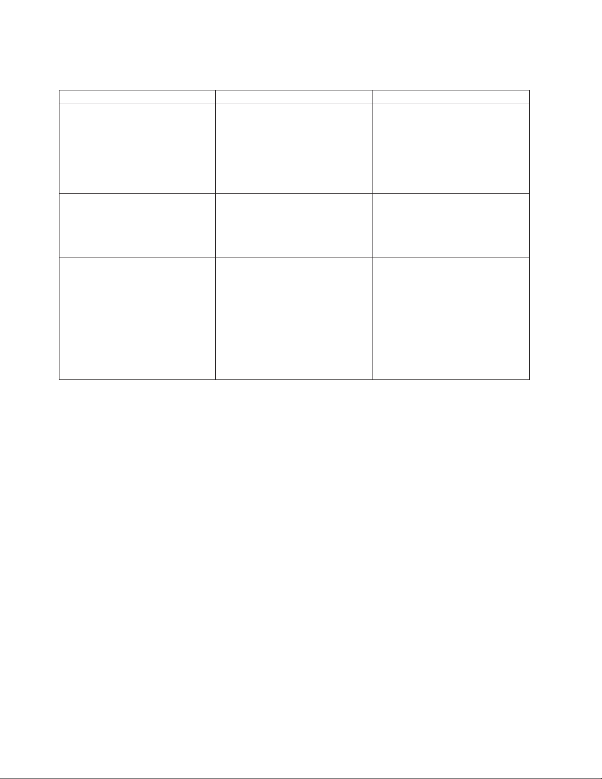
Table 1. Solid-state drive rules for the IBM AIX, IBM i, or Linux operating system for a system, enclosure, or
expansion unit
System, enclosure, or expansion unit Adapter Mixing rules
8202-E4B, 8202-E4C, 8202-E4D,
8205-E6B, 8205-E6C, or 8205-E6D
5802 and 5877 FC 5903 (PCIe 380 MB Cache Dual x4
5886
v FC 5631 (Split disks enablement
adapter)
3 Gb SAS RAID Adapter)
v FC 5904 (PCI-X DDR 1.5 GB Cache
SAS RAID Adapter)
v FC 5906 and FC 5908 (PCI-X DDR
1.5 GB Cache SAS RAID Adapter)
v FC 5903 (PCIe 380 MB Cache Dual
- x4 3 Gb SAS RAID Adapter)
v SSD and HDD cannot be mixed in
the same RAID array or mirroring
group.
v SSDs and HDDs can be connected
to the 5886 from the external SAS
port.
v 5631 can be used to split disks
v SSD and HDD cannot be mixed on
a pair of 5903 adapters.
v A maximum of 9 SSDs are
supported on a pair of 5903
adapters.
v SSDs and HDDs can be mixed in
this drive enclosure.
v A maximum of 24 drives are
supported in this enclosure.
v SSDs and HDDs can be attached to
the SAS Controller PCI or PCI-X
adapters. Also, can be attached to
the embedded SAS controller in a
system with an embedded SAS
port.
2 Disk drives or solid-state drives
Page 19

Table 1. Solid-state drive rules for the IBM AIX, IBM i, or Linux operating system for a system, enclosure, or
expansion unit (continued)
System, enclosure, or expansion unit Adapter Mixing rules
5887 disk drive enclosure
v FC 5805 (PCIe 380 MB Cache Dual
- x4 3 Gb SAS RAID Adapter)
v FC 5901 (PCIe Dual x4 SAS
Adapter)
v FC 5908 (PCI-X DDR 1.5 GB Cache
SAS RAID Adapter)
v FC ESA1 (PCIe2 RAID SAS
Adapter Dual-port 6 Gb)
v FC ESA1 (PCIe2 LP RAID SAS
Adapter Dual-port 6 Gb)
v PCIe2 (3.1 GB Cache RAID SAS
Enclosure 6 Gb x8)
v A maximum of 24 drives are
supported in this enclosure.
v The EXP24S can be configured as
one set of 24 bays (mode 1), two
sets of 12 bays (mode 2), or four
sets of 6 bays (mode 4).
v The EXP24S serial-attached SCSI
(SAS) ports are attached to SAS
controllers, which can be a SAS
Peripheral Component
Interconnect-X (PCI-X) adapter, PCI
Express (PCIe) adapter, or a pair of
adapters. The EXP24S can also be
attached to an embedded SAS
controller in a system with an
embedded SAS port.
v The mixing of the SSDs and HDDs
is as follows:
– SSDs and HDDs cannot be
mixed in a logical group when
configured as in mode 1.
– SSDs and HDDs can be mixed
when configured as in mode 2:
one set can be SSDs and the
other set can be HDDs.
– SSDs and HDDs cannot be
mixed when configured as in
mode 4 because the SSDs are
not supported by the adapter
that is required to configure the
5887 for mode 4.
Disk drives or solid-state drives 3
Page 20
Table 1. Solid-state drive rules for the IBM AIX, IBM i, or Linux operating system for a system, enclosure, or
expansion unit (continued)
System, enclosure, or expansion unit Adapter Mixing rules
5888 PCIe storage enclosure PCIe2 (3.1 GB Cache RAID SAS
Enclosure 6 Gb x8)
v This enclosure is a 1-unit (1U) high
I/O drawer that provides 30
hot-swap SSD bays and a pair of
integrated SAS controllers. The
SAS controllers provide large write
cache and enhanced performance.
v The EXP30 does not support
HDDs.
v A maximum of 30 SSDs are
supported in this disk drive
enclosure.
v The EXP30 can be configured as
follows:
– One set of 30 bays and the set is
owned by both controllers that
are working together.
– Two logical sets and each of the
two controllers owns one of the
logical sets.
v The EXP30 is attached to the
system by a PCIe x8 cable that is
installed at the GX ++ slot in the
system.
v The system supports connection of
the 5887 disk drive enclosure
through the external SAS ports by
using FC 5913, ESA1, or ESA2.
v The system supports only the
HDD in the 5887 disk drive
enclosure when this enclosure is
configured as one set of 24 bays
(mode 1).
4 Disk drives or solid-state drives
Page 21

Table 1. Solid-state drive rules for the IBM AIX, IBM i, or Linux operating system for a system, enclosure, or
expansion unit (continued)
System, enclosure, or expansion unit Adapter Mixing rules
EDR1 PCIe storage enclosure PCIe2 (3.1 GB Cache RAID SAS
Enclosure 6 Gb x8)
v This enclosure is a 1-unit (1U) high
I/O drawer that provides 30
hot-swap SSD bays and a pair of
integrated SAS controllers. The
SAS controllers provide large write
cache and enhanced performance.
v The EXP30 does not support
HDDs.
v A maximum of 30 SSDs are
supported in this disk drive
enclosure.
v The EXP30 can be configured as
follows:
– One set of 30 bays and the set is
owned by both controllers that
are working together.
– Two logical sets and each of the
two controllers owns one of the
logical sets.
v The EXP30 is attached to the
system by a PCIe x8 cable that is
installed at the GX ++ slot in the
system.
Installing a disk drive or solid-state drive in an 8202-E4B, 8202-E4C,
8202-E4D, 8205-E6B, 8205-E6C, or 8205-E6D with the AIX system or
logical partition power turned on
Learn how to install a disk drive or solid-state drive in a system or expansion unit with the AIX
operating system or logical partition that controls the drive location is powered on.
If you are servicing a failing part, see the service procedures for “Replacing a disk drive or solid-state
drive in the 8202-E4B, 8202-E4C, 8202-E4D, 8205-E6B, 8205-E6C, or 8205-E6D with the AIX system or
logical partition power turned on” on page 63.
Before installing or replacing a feature, ensure that the software required to support the feature is
installed on the system. For information about software prerequisites, see IBM Prerequisite website
(www-912.ibm.com/e_dir/eServerPrereq.nsf). If the required software is not installed, go to Fix Central
(www.ibm.com/support/fixcentral) to download it, and install it before continuing.
If you are installing solid-state drives, review the configuration rules and then return here. For more
information, see “Solid-state drive configuration rules for the 8202-E4B, 8202-E4C, 8202-E4D, 8205-E6B,
8205-E6C, or 8205-E6D” on page 1.
®
Disk drives or solid-state drives 5
Page 22

Attention:
v Attach a wrist strap to an unpainted metal surface of your hardware to prevent electrostatic discharge
(ESD) from damaging your hardware.
v When using a wrist strap, follow all electrical safety procedures. A wrist strap is for static control. It
does not increase or decrease your risk of receiving electric shock when using or working on electrical
equipment.
v If you do not have a wrist strap, just prior to removing the product from ESD packaging and installing
or replacing hardware, touch an unpainted metal surface of the system for a minimum of 5 seconds.
Note: Some of the figures in these procedures might not look exactly like the system or expansion unit
that you have. However, the steps to complete the task are the same.
Complete the following tasks to install a drive:
v “Preparing to install a disk drive or solid-state drive”
v “Preparing to install a disk drive or solid-state drive by using the diagnostic command” on page 7
v Select from the following options:
– “Installing a disk drive or solid-state drive in the 8202-E4B, 8202-E4C, 8202-E4D, 8205-E6B,
8205-E6C, or 8205-E6D system or expansion unit” on page 7
– “Installing a disk drive or solid-state drive in the 5887 disk drive enclosure” on page 8
– “Installing a solid-state drive in the 5888 PCIe storage enclosure” on page 9 (This drive enclosure is
supported for the 8202-E4C and 8205-E6C systems.)
– “Installing a solid-state drive in the EDR1 PCIe storage enclosure” on page 10 (This drive enclosure
is supported for the 8202-E4D and 8205-E6D systems.)
v “Completing the disk drive or solid-state drive installation by using the diagnostic command” on page
11
v “Completing the procedure” on page 11
Preparing to install a disk drive or solid-state drive
Complete the following steps before installing a disk drive or solid-state drive in a system or in an
expansion unit:
1. Complete the prerequisite tasks. For instructions, see “Before you begin” on page 137.
2. Identify the system for performing the installation or upgrading by turning on the system identify
(blue) LED. For instructions, see Control panel LEDs and Enabling enclosure indicators.
3. If applicable, remove the system unit door, remove the expansion unit door, or open the rack.
4. Remove the front cover:
v For instructions for a rack-mounted system, see “Removing the front cover from a rack-mounted
system” on page 151.
v For instructions for a stand-alone system, see “Removing the front cover from a stand-alone
8202-E4B, 8202-E4C, 8202-E4D, or 8205-E6B system” on page 152.
5. Determine the next available disk drive or solid-state drive position in the system or an expansion
unit. For information, see “Disk drive locations and service indicators for the 8202-E4B, 8202-E4C,
8202-E4D, 8205-E6B, 8205-E6C, or 8205-E6D system” on page 97.
Note: When you have a system with an expansion unit, fill the slot positions in the system unit first.
However, you can choose a different disk drive or solid-state drive placement depending on your
data protection strategy.
6. Find the package that contains the new drive.
Attention: Drives are fragile. Handle with care.
7. Remove the drive from the static-protective package.
8. Proceed to preparing to install the disk drive or solid-state drive by using the diagnostic command.
6 Disk drives or solid-state drives
Page 23

Preparing to install a disk drive or solid-state drive by using the diagnostic command
Complete the following steps before installing a disk drive or solid-state drive in a system or in an
expansion unit:
1. Log in as root user.
2. At the command line, type diag and press Enter.
3. On the Diagnostic Operating Instructions display, press Enter to continue.
4. On the Function Selection display, select Task Selection.
5. Select RAID Array Manager.
6. Depending on the adapter that your drive is attached to, select IBM SAS Disk Array Manager, PCI
SCSI Disk Array Manager,orPCI-X SCSI Disk Array Manager.
7. Select Diagnostics and Recovery Options.
8. Select SCSI and SCSI RAID Hot Plug Manager.
9. Select Attach a Device to a SCSI Hot Swap Enclosure Device. A list of empty slots in the SCSI hot
swap enclosure device is shown.
Choose from the following options:
v If you are installing a drive in a system or an expansion unit, proceed to “Installing a disk drive or
solid-state drive in the 8202-E4B, 8202-E4C, 8202-E4D, 8205-E6B, 8205-E6C, or 8205-E6D system or
expansion unit.”
v If you are installing a drive in the 5887 disk drive enclosure, proceed to “Installing a disk drive or
solid-state drive in the 5887 disk drive enclosure” on page 8.
v If you are installing a drive in the 5888 PCIe storage enclosure, proceed to “Installing a solid-state
drive in the 5888 PCIe storage enclosure” on page 9.
v If you are installing a drive in the EDR1 PCIe storage enclosure, proceed to “Installing a solid-state
drive in the EDR1 PCIe storage enclosure” on page 10.
Installing a disk drive or solid-state drive in the 8202-E4B, 8202-E4C, 8202-E4D,
8205-E6B, 8205-E6C, or 8205-E6D system or expansion unit
Complete the following steps to install a disk drive or solid-state drive in a system or in an expansion
unit:
1. If the slot you want to use contains a disk drive filler, remove the disk drive filler from the slot. For
instructions, see “Removing a disk drive filler from the 8202-E4B, 8202-E4C, 8202-E4D, 8205-E6B,
8205-E6C, or 8205-E6D” on page 92.
2. If the drive you are installing does not have a bezel preinstalled, then complete the tasks to install a
bezel on the drive, then continue with this procedure from step 3. For instructions to install a bezel,
see “Installing a disk drive bezel in a drive or filler for the 8202-E4B, 8202-E4C, 8202-E4D, 8205-E6B,
8205-E6C, or 8205-E6D” on page 95.
3. Unlock the drive handle by squeezing it and pulling it out toward you. If the handle is not all the
way out, the drive does not slide into the system or expansion unit.
4. Hold the drive by the top and bottom edges as you position the drive, and insert it into the system or
the expansion unit.
Note: Do not hold the drive only by the handle. Support the drive by holding the drive by its sides.
5. Slide the drive halfway into the system or expansion unit.
6. Select the drive that you want to install and press Enter on the console.
7. When the identify LED turns on solid, slide the drive all the way into the system or an expansion
unit, and push the drive handle in until it locks. See Figure 1 on page 8.
Disk drives or solid-state drives 7
Page 24
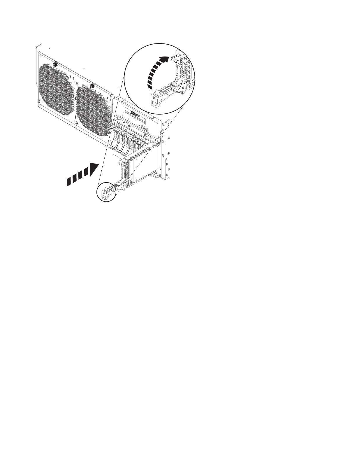
Figure 1. Installing the disk drive in the system
8. On the console, press Enter to indicate that you have installed the drive.
9. If you are installing more than one disk drive or solid-state drive, repeat the steps in this procedure
until all disk drives or solid-state drives are installed.
Proceed to the procedure for completing the disk drive or solid-state drive installation. For instructions,
go to “Completing the disk drive or solid-state drive installation by using the diagnostic command” on
page 11.
Installing a disk drive or solid-state drive in the 5887 disk drive enclosure
Complete the following steps to install a disk drive or solid-state drive in the 5887 disk drive enclosure:
1. With the handle in the unlocked position, as shown in Figure 2 on page 9, support the bottom of the
drive as you align it with the guide rails in the expansion unit.
Note: Do not hold the drive only by the handle. Support the drive by holding the drive by its sides.
2. Slide the drive halfway into the 5887 disk drive enclosure.
3. Select the drive that you want to install and press Enter on the console.
4. When the identify LED turns on solid, slide the drive into the 5887 disk drive enclosure until the
drive stops.
Important: When installing a drive, ensure that the drive is fully seated and is all the way into the
enclosure.
5. Rotate the handle to the locked position.
8 Disk drives or solid-state drives
Page 25
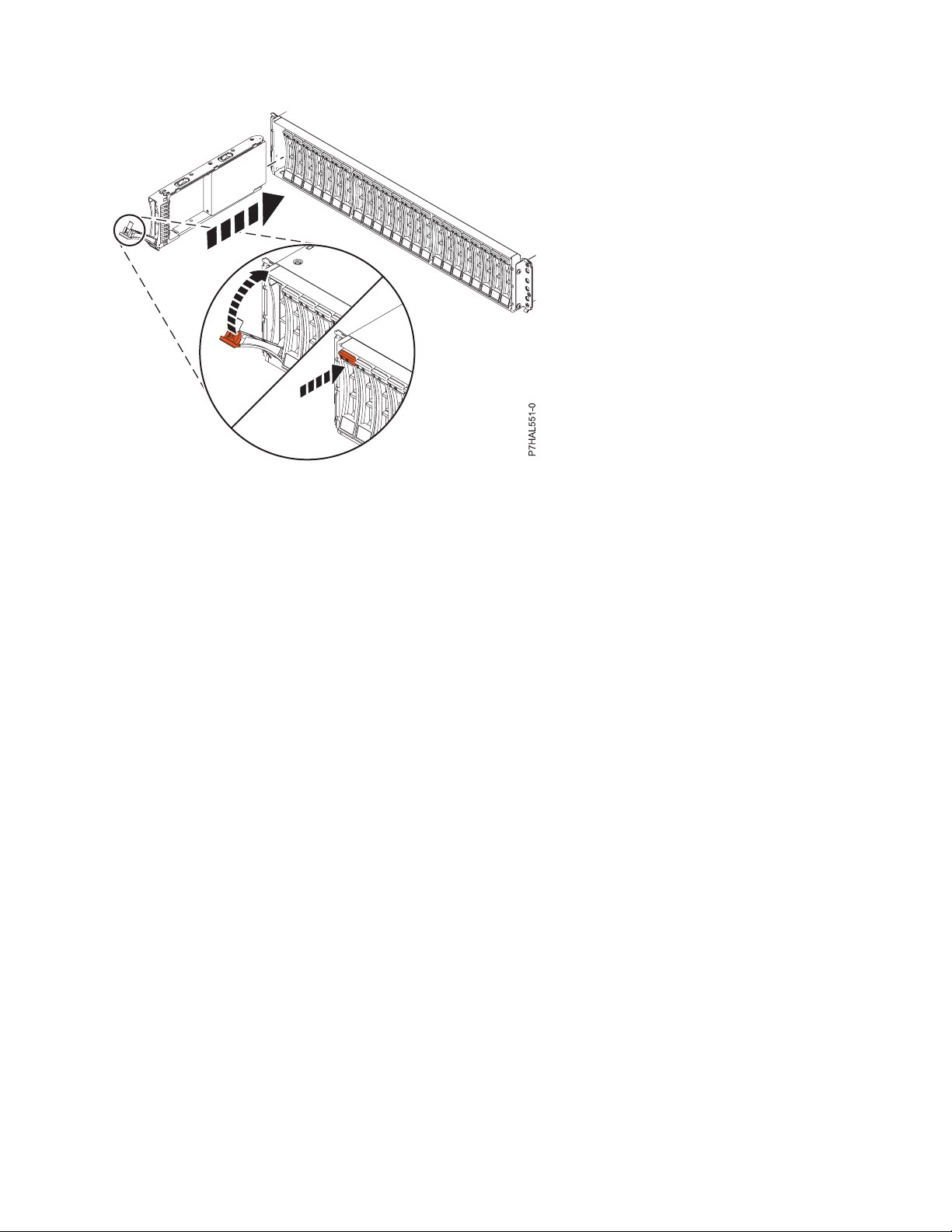
Figure 2. Installing the disk drive in the 5887 disk drive enclosure
6. On the console, press Enter to indicate that you have installed the drive.
Proceed to the procedure for completing the disk drive or solid-state drive installation. For instructions,
go to “Completing the disk drive or solid-state drive installation by using the diagnostic command” on
page 11.
Installing a solid-state drive in the 5888 PCIe storage enclosure
Complete the following steps to install a solid-state drive in the 5888 PCIe storage enclosure.
1. With the handle in the unlocked position, align the solid-state drive with the guide rails in the
enclosure. See Figure 3 on page 10.
Note: Do not hold the solid-state drive only by the handle. Support the drive by holding the drive by
its sides.
2. Slide the drive halfway into the 5888 PCIe storage enclosure.
3. Select the drive that you want to install and press Enter on the console.
4. When the identify LED turns on solid, slide the solid-state drive into the 5888 PCIe storage enclosure
until the drive stops.
Important: When installing a drive, ensure that the drive is fully seated and is all the way into the
5888 PCIe storage enclosure.
5. Rotate the handle (A) to the locked position.
6. Install the bezel (B).
Disk drives or solid-state drives 9
Page 26
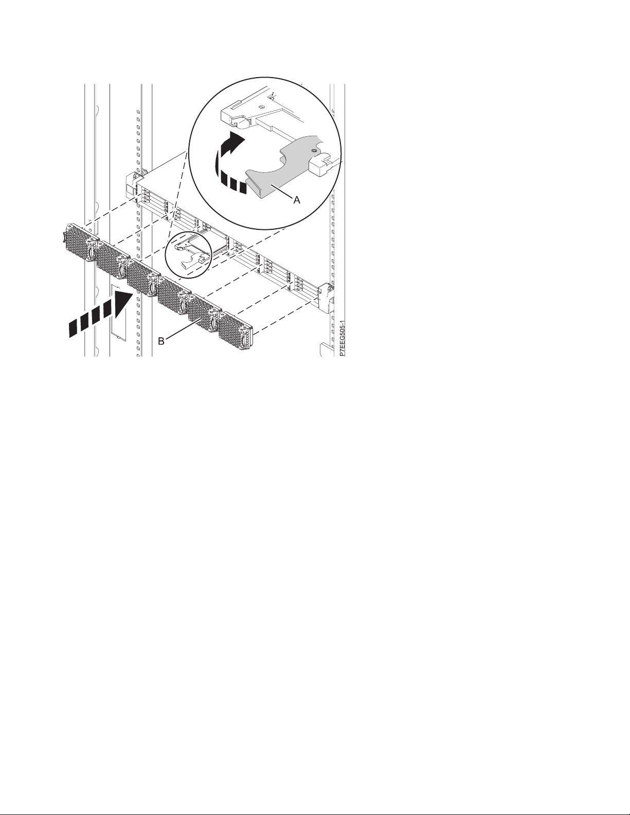
Figure 3. Installing a solid-state drive in the 5888 PCIe storage enclosure
7. On the console, press Enter to indicate that you have installed the drive.
Proceed to the procedure for completing the disk drive or solid-state drive installation. For instructions,
go to “Completing the disk drive or solid-state drive installation by using the diagnostic command” on
page 11.
Installing a solid-state drive in the EDR1 PCIe storage enclosure
Complete the following steps to install a solid-state drive in the EDR1 PCIe storage enclosure:
1. With the handle in the unlocked position, align the solid-state drive with the guide rails in the
enclosure. See Figure 4 on page 11.
Note: Do not hold the solid-state drive only by the handle. Support the drive by holding the drive by
its sides.
2. Slide the drive halfway into the EDR1 PCIe storage enclosure.
3. Select the drive that you want to install and press Enter on the console.
4. When the identify LED turns on solid, slide the solid-state drive into the EDR1 PCIe storage enclosure
until the drive stops.
Important: When installing a drive, ensure that the drive is fully seated and is all the way into the
EDR1 PCIe storage enclosure.
5. Rotate the handle (A) to the locked position.
6. Install the bezel (B).
10 Disk drives or solid-state drives
Page 27
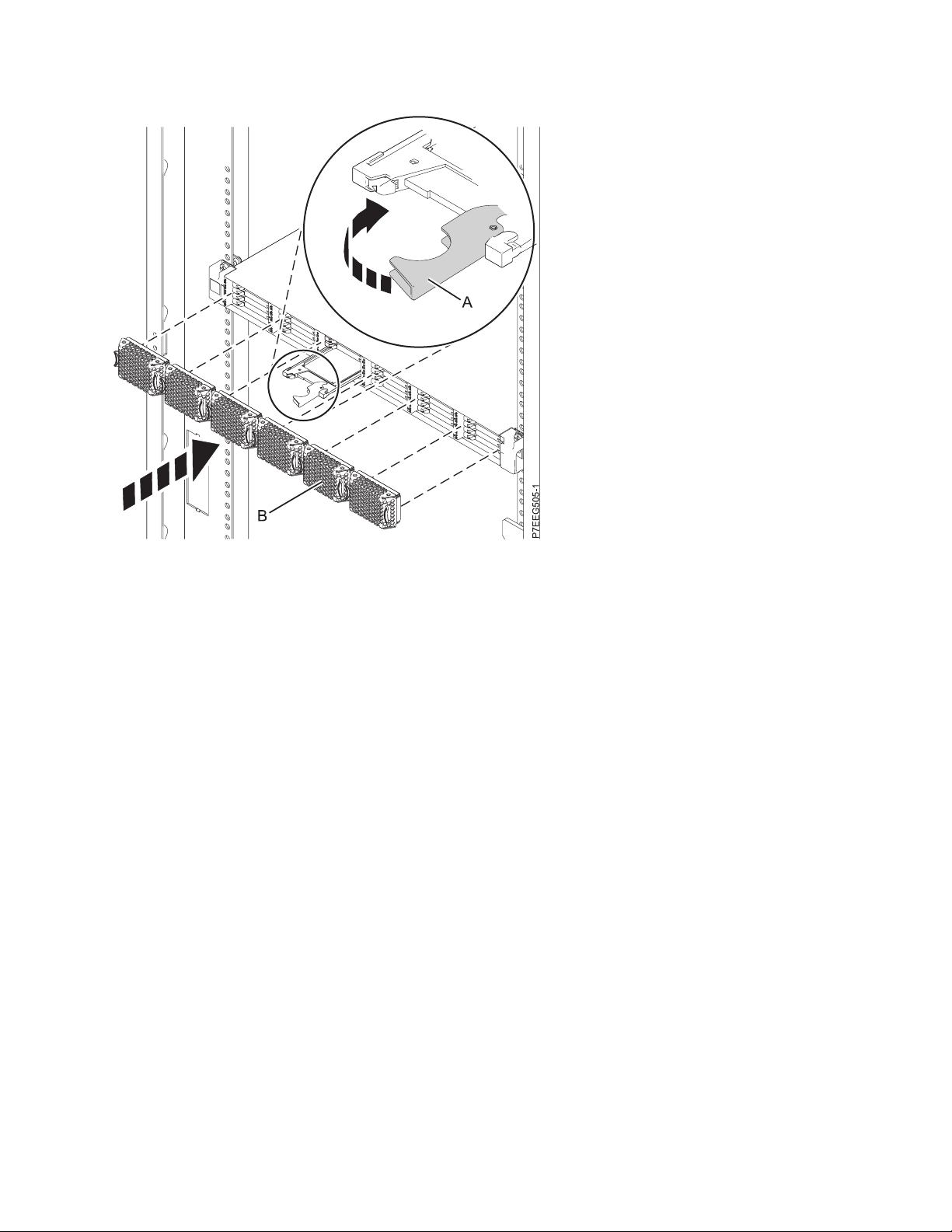
Figure 4. Installing a solid-state drive in the EDR1 PCIe storage enclosure
7. On the console, press Enter to indicate that you have installed the drive.
Proceed to the procedure for completing the disk drive or solid-state drive installation. For instructions,
go to “Completing the disk drive or solid-state drive installation by using the diagnostic command.”
Completing the disk drive or solid-state drive installation by using the diagnostic command
Complete the following steps after you install or replace the disk drive or solid-state drive in a system or
in an expansion unit:
1. Complete the following steps by using the diagnostic command:
a. Press Enter.
b. Exit to the command line.
c. If you are installing more than one disk drive or solid-state drive, repeat this procedure until all
disk drives or solid-state drives are installed.
d. Press Cancel. The SCSI and SCSI RAID Hot Plug Manager menu is displayed.
e. Select Configure Added/Replaced Devices.
2. Proceed to completing the procedure.
Completing the procedure
Complete the following steps after you install or replace the disk drive or solid-state drive in a system,
enclosure, or expansion unit:
1. Replace the front cover:
v For instructions for a rack-mounted system, see “Installing the front cover on a rack-mounted
8202-E4B, 8202-E4C, 8202-E4D, 8205-E6B, 8205-E6C, or 8205-E6D system” on page 153.
v For instructions for a stand-alone system, see “Installing the front cover and front door on a
stand-alone 8202-E4B, 8202-E4C, 8202-E4D, or 8205-E6B system” on page 154.
2. Verify the installed part:
Disk drives or solid-state drives 11
Page 28

v If you replaced the part because of a failure, verify the installed part. For instructions, see
“Verifying a repair” on page 177.
v If you installed the part for any other reason, verify the installed part. For instructions, see
“Verifying the installed part” on page 165.
3. To configure the newly installed disk drive or solid-state drive, see “Preparing a disk drive or
solid-state drive for use in an AIX system or logical partition” on page 107.
4. To rebuild the data on the replacement disk drive or solid-state drive, see “Rebuilding data on a
replacement disk drive or solid-state drive by using AIX” on page 108.
Installing a disk drive or solid-state drive in the 8202-E4B, 8202-E4C,
8202-E4D, 8205-E6B, 8205-E6C, or 8205-E6D with the Linux system or
logical partition power turned on
Learn how to install a disk drive or solid-state drive in a system or expansion unit with the Linux
operating system or logical partition that controls the drive location is powered on.
If you are servicing a failing part, see the service procedures for “Replacing a disk drive in the 8202-E4B,
8202-E4C, 8202-E4D, 8205-E6B, 8205-E6C, or 8205-E6D with the power to the Linux system or logical
partition turned on” on page 68.
Before installing or replacing a feature, ensure that the software required to support the feature is
installed on the system. For information about software prerequisites, see IBM Prerequisite website
(www-912.ibm.com/e_dir/eServerPrereq.nsf). If the required software is not installed, go to Fix Central
(www.ibm.com/support/fixcentral) to download it, and install it before continuing.
If you are installing solid-state drives, review the configuration rules and then return here. For more
information, see “Solid-state drive configuration rules for the 8202-E4B, 8202-E4C, 8202-E4D, 8205-E6B,
8205-E6C, or 8205-E6D” on page 1.
Complete the following tasks to install a drive:
v “Preparing to install a disk drive or solid-state drive”
v “Preparing to install a disk drive or solid-state drive by using the iprconfig command” on page 13
v Select from the following options:
– “Installing a disk drive or solid-state drive in the 8202-E4B, 8202-E4C, 8202-E4D, 8205-E6B,
8205-E6C, or 8205-E6D system or expansion unit” on page 14
– “Installing a disk drive or solid-state drive in the 5887 disk drive enclosure” on page 15
– “Installing a solid-state drive in the 5888 PCIe storage enclosure” on page 16 (This drive enclosure is
supported for the 8202-E4C and 8205-E6C systems.)
– “Installing a solid-state drive in the EDR1 PCIe storage enclosure” on page 17 (This drive enclosure
is supported for the 8202-E4D and 8205-E6D systems.)
v “Verifying that the new disk drive or solid-state drive is installed and operational” on page 18
v “Completing the procedure” on page 19
Preparing to install a disk drive or solid-state drive
Complete the following steps before installing a disk drive or solid-state drive in a system or in an
expansion unit:
1. Complete the prerequisite tasks. For instructions, see “Before you begin” on page 137.
2. Identify the system for performing the installation or upgrading by turning on the system identify
(blue) LED. For instructions, see Control panel LEDs and Enabling enclosure indicators.
3. If applicable, remove the system unit door, remove the expansion unit door, or open the rack.
4. Remove the front cover:
12 Disk drives or solid-state drives
Page 29

v For instructions for a rack-mounted system, see “Removing the front cover from a rack-mounted
system” on page 151.
v For instructions for a stand-alone system, see “Removing the front cover from a stand-alone
8202-E4B, 8202-E4C, 8202-E4D, or 8205-E6B system” on page 152.
5. Determine the next available disk drive or solid-state drive position in the system or an expansion
unit. For information, see “Disk drive locations and service indicators for the 8202-E4B, 8202-E4C,
8202-E4D, 8205-E6B, 8205-E6C, or 8205-E6D system” on page 97.
Note: When you have a system with an expansion unit, fill the slot positions in the system unit first.
However, you can choose a different disk drive or solid-state drive placement depending on your
data protection strategy.
6. Find the package that contains the new drive.
Attention: Drives are fragile. Handle with care.
7. Remove the drive from the static-protective package.
8. Proceed to installing a disk drive or solid-state drive in the system or disk drive enclosure by using
the iprconfig command.
Preparing to install a disk drive or solid-state drive by using the iprconfig command
Complete the following steps before installing a disk drive or solid-state drive in a system or in an
expansion unit:
1. Log in as root user.
2. Type iprconfig on the command line of the Linux session, and then press Enter. The IBM Power
RAID Configuration Utility display is shown.
3. Select Work with disk unit recovery from the IBM Power RAID Configuration Utility display. Press
Enter.
4. Select Concurrent add device from the Work with Disk Unit Recovery display. Press Enter.
A Concurrent Device Add display, similar to the following figure, is shown.
Disk drives or solid-state drives 13
Page 30

Concurrent Device Add
Choose a single location for add operations
1=Select
OPT Name PCI/SCSI Location Description Status
--- ------ -------------------------- ------------------------- -----------------
U5887.001.Z065075-P1-D1 Empty
U5887.001.Z065075-P1-D6 Empty
U5887.001.Z065075-P1-D7 Empty
U5887.001.Z065075-P1-D8 Empty
U5887.001.Z065075-P1-D9 Empty
e=Exit q=Cancel t=Toggle
Figure 5. Example Concurrent Device Add display
5. Type t if you want to toggle through different location code representations.
6. Type 1 next to the location into which you want to install the disk drive or solid-state drive and press
Enter.
The Verify Device Concurrent Add display is shown.
A service indicator flashes for the slot where the disk drive or solid-state drive can be installed.
Choose from the following options:
v If you are installing a drive in a system or an expansion unit, proceed to “Installing a disk drive or
solid-state drive in the 8202-E4B, 8202-E4C, 8202-E4D, 8205-E6B, 8205-E6C, or 8205-E6D system or
expansion unit.”
v If you are installing a drive in the 5887 disk drive enclosure, proceed to “Installing a disk drive or
solid-state drive in the 5887 disk drive enclosure” on page 15.
v If you are installing a drive in the 5888 PCIe storage enclosure, proceed to “Installing a solid-state
drive in the 5888 PCIe storage enclosure” on page 16.
v If you are installing a drive in the EDR1 PCIe storage enclosure, proceed to “Installing a solid-state
drive in the EDR1 PCIe storage enclosure” on page 17.
Installing a disk drive or solid-state drive in the 8202-E4B, 8202-E4C, 8202-E4D,
8205-E6B, 8205-E6C, or 8205-E6D system or expansion unit
Complete the following steps to install a disk drive or solid-state drive in a system or in an expansion
unit:
1. If the slot you want to use contains a disk drive filler, remove the disk drive filler from the slot. For
instructions, see “Removing a disk drive filler from the 8202-E4B, 8202-E4C, 8202-E4D, 8205-E6B,
8205-E6C, or 8205-E6D” on page 92.
2. If the drive you are installing does not have a bezel preinstalled, then complete the tasks to install a
bezel on the drive, then continue with this procedure from step 3 on page 15. For instructions to
install a bezel, see “Installing a disk drive bezel in a drive or filler for the 8202-E4B, 8202-E4C,
8202-E4D, 8205-E6B, 8205-E6C, or 8205-E6D” on page 95.
14 Disk drives or solid-state drives
Page 31

3. Unlock the drive handle (A) by squeezing it and pulling it out toward you. If the handle is not all the
way out, the drive does not slide into the system or expansion unit.
4. Hold the drive by the top and bottom edges as you position the drive, and insert it into the system or
the expansion unit.
Note: Do not hold the drive only by the handle. Support the drive by holding the drive by its sides.
5. Slide the drive halfway into the system or expansion unit.
6. On the Verify Device Concurrent Add display, verify that the selected drive is the drive you want to
install, then press Enter.
7. When the identify LED flashes, slide the drive all the way into the system or an expansion unit, and
push the drive handle (A) in until it locks, as shown in Figure 6.
Figure 6. Installing the disk drive in the system
8. On the console, press Enter to indicate that you have installed the drive.
9. If you are installing more than one disk drive or solid-state drive, repeat the steps in this procedure
until all disk drives or solid-state drives are installed.
Proceed to the procedure for verifying the drive installation. For instructions, go to “Verifying that the
new disk drive or solid-state drive is installed and operational” on page 18.
Installing a disk drive or solid-state drive in the 5887 disk drive enclosure
Complete the following steps to install a disk drive or solid-state drive in the 5887 disk drive enclosure:
1. With the handle in the unlocked position, see Figure 7 on page 16, support the bottom of the drive as
you align it with the guide rails in the expansion unit.
Note: Do not hold the drive only by the handle. Support the drive by holding the drive by its sides.
2. Slide the drive halfway into the 5887 disk drive enclosure.
3. On the Verify Device Concurrent Add display, verify that the selected drive is the drive you want to
replace, then press Enter.
Disk drives or solid-state drives 15
Page 32

4. When the identify LED flashes, slide the drive into the 5887 disk drive enclosure until the drive stops.
Important: When installing a drive, ensure that the drive is fully seated and is all the way into the
enclosure.
5. Rotate the handle to the locked position.
Figure 7. Installing the disk drive in the 5887 disk drive enclosure
6. On the console, press Enter to indicate that you have installed the drive.
Proceed to the procedure for verifying the drive installation. For instructions, go to “Verifying that the
new disk drive or solid-state drive is installed and operational” on page 18.
Installing a solid-state drive in the 5888 PCIe storage enclosure
Complete the following steps to install a solid-state drive in the 5888 PCIe storage enclosure.
1. With the handle in the unlocked position, align the solid-state drive with the guide rails in the
enclosure. See Figure 8 on page 17.
Note: Do not hold the solid-state drive only by the handle. Support the drive by holding the drive by
its sides.
2. Slide the drive halfway into the 5888 PCIe storage enclosure.
3. On the Verify Device Concurrent Add display, verify that the selected drive is the drive you want to
replace, then press Enter.
4. When the identify LED flashes, slide the solid-state drive into the 5888 PCIe storage enclosure until
the drive stops.
Important: When installing a drive, ensure that the drive is fully seated and is all the way into the
5888 PCIe storage enclosure.
5. Rotate the handle (A) to the locked position.
6. Install the bezel (B).
16 Disk drives or solid-state drives
Page 33

Figure 8. Installing a solid-state drive in the 5888 PCIe storage enclosure
Proceed to the procedure for verifying the drive installation. For instructions, go to “Verifying that the
new disk drive or solid-state drive is installed and operational” on page 18.
Installing a solid-state drive in the EDR1 PCIe storage enclosure
Complete the following steps to install a solid-state drive in the EDR1 PCIe storage enclosure:
1. With the handle in the unlocked position, align the solid-state drive with the guide rails in the
enclosure. See Figure 9 on page 18.
Note: Do not hold the solid-state drive only by the handle. Support the drive by holding the drive by
its sides.
2. Slide the drive halfway into the EDR1 PCIe storage enclosure.
3. On the Verify Device Concurrent Add display, verify that the selected drive is the drive you want to
replace, then press Enter.
4. When the identify LED flashes, slide the solid-state drive into the EDR1 PCIe storage enclosure until
the drive stops.
Important: When installing a drive, ensure that the drive is fully seated and is all the way into the
EDR1 PCIe storage enclosure.
5. Rotate the handle (A) to the locked position.
6. Install the bezel (B).
Disk drives or solid-state drives 17
Page 34

Figure 9. Installing a solid-state drive in the EDR1 PCIe storage enclosure
7. On the console, press Enter to indicate that you have installed the drive.
Proceed to the procedure for verifying the drive installation. For instructions, go to “Verifying that the
new disk drive or solid-state drive is installed and operational.”
Verifying that the new disk drive or solid-state drive is installed and operational
Press Enter on the Complete Device Concurrent Add display to indicate that the disk drive or solid-state
drive is installed. The identify LED turns off.
Complete the following steps to verify that the new disk drive or solid-state drive is operational:
1. Log in as root user.
2. Type iprconfig on the command line of the Linux session and press Enter. The IBM Power RAID
Configuration Utility display is shown.
3. Select Display hardware status. The Display Hardware Status display is shown, similar to the
following figure.
18 Disk drives or solid-state drives
Page 35

Display Hardware Status
Type option, press Enter.
1=Display hardware resource information details
OPT Name PCI/SCSI Location Description Status
--- ------ -------------------------- ------------------------- ----------------
0000:01:00.0/0: PCI-E SAS RAID Adapter Operational
0000:01:00.0/0:0:0:0 Advanced Function SSD Active
0000:01:00.0/0:0:1:0 Advanced Function SSD Active
0000:01:00.0/0:0:2:0 Advanced Function SSD Active
0000:01:00.0/0:0:3:0 Advanced Function SSD Active
0000:01:00.0/0:0:4:0 Advanced Function SSD Active
0000:01:00.0/0:0:5:0 Advanced Function SSD Active
0000:01:00.0/0:0:6:0 Advanced Function SSD Active
0000:01:00.0/0:0:8:0 Enclosure Active
0000:01:00.0/0:0:9:0 Enclosure Active
0001:01:00.0/1: PCI-E SAS RAID Adapter Operational
0001:01:00.0/1:0:3:0 Advanced Function SSD Remote
0001:01:00.0/1:0:4:0 Advanced Function SSD Remote
0001:01:00.0/1:0:5:0 Advanced Function SSD Remote
More...
e=Exit q=Cancel r=Refresh t=Toggle f=PageDn b=PageUp
Figure 10. Example Display Hardware Status
4. Verify that the disk drive or solid-state drive that you installed is shown on this display.
Proceed to completing the procedure.
Completing the procedure
Complete the following steps after you install or replace the disk drive or solid-state drive in a system,
enclosure, or expansion unit:
1. Replace the front cover:
v For instructions for a rack-mounted system, see “Installing the front cover on a rack-mounted
8202-E4B, 8202-E4C, 8202-E4D, 8205-E6B, 8205-E6C, or 8205-E6D system” on page 153.
v For instructions for a stand-alone system, see “Installing the front cover and front door on a
stand-alone 8202-E4B, 8202-E4C, 8202-E4D, or 8205-E6B system” on page 154.
2. Verify the installed part:
v If you replaced the part because of a failure, verify the installed part. For instructions, see
“Verifying a repair” on page 177.
Disk drives or solid-state drives 19
Page 36

v If you installed the part for any other reason, verify the installed part. For instructions, see
“Verifying the installed part” on page 165.
3. To rebuild data on the newly installed or replaced disk drive or solid-state drive, see “Rebuilding data
on a replacement disk drive or solid-state drive in a system or logical partition running Linux” on
page 111.
Installing a disk drive or solid-state drive in the 8202-E4B, 8202-E4C,
8202-E4D, 8205-E6B, 8205-E6C, or 8205-E6D with the IBM i system or
logical partition power turned on
Learn how to install a disk drive or solid-state drive in a system or expansion unit with the IBM i
operating system or logical partition that controls the drive location is powered on.
If you are servicing a failing part, see the service procedures for “Replacing a disk drive or solid-state
drive in the 8202-E4B, 8202-E4C, 8202-E4D, 8205-E6B, 8205-E6C, or 8205-E6D with the IBM i system or
logical partition power turned on” on page 73.
Before installing or replacing a feature, ensure that the software required to support the feature is
installed on the system. For information about software prerequisites, see IBM Prerequisite website
(www-912.ibm.com/e_dir/eServerPrereq.nsf). If the required software is not installed, go to Fix Central
(www.ibm.com/support/fixcentral) to download it, and install it before continuing.
If you are installing solid-state drives, review the configuration rules and then return here. For more
information, see “Solid-state drive configuration rules for the 8202-E4B, 8202-E4C, 8202-E4D, 8205-E6B,
8205-E6C, or 8205-E6D” on page 1.
Note: Some of the figures in these procedures might not look exactly like the system or expansion unit
that you have. However, the steps to complete the task are the same.
Complete the following tasks to install a drive:
v “Preparing to install a disk drive or solid-state drive”
v “Preparing to install a disk drive or solid-state drive by using the HSM” on page 21
v Select from the following options:
– “Installing a disk drive or solid-state drive in the 8202-E4B, 8202-E4C, 8202-E4D, 8205-E6B,
8205-E6C, or 8205-E6D system or expansion unit” on page 22
– “Installing a disk drive or solid-state drive in the 5887 disk drive enclosure” on page 24
– “Installing a solid-state drive in the EDR1 PCIe storage enclosure” on page 24 (This drive enclosure
is supported for the 8202-E4D and 8205-E6D systems.)
v “Completing the disk drive or solid-state drive installation” on page 25
v “Completing the procedure” on page 25
Preparing to install a disk drive or solid-state drive
Complete the following steps before installing a disk drive or solid-state drive in a system or in an
expansion unit:
1. Complete the prerequisite tasks. For instructions, see “Before you begin” on page 137.
2. Identify the system for performing the installation or upgrading by turning on the system identify
(blue) LED. For instructions, see Control panel LEDs and Enabling enclosure indicators.
3. If applicable, remove the system unit door, remove the expansion unit door, or open the rack.
4. Remove the front cover:
v For instructions for a rack-mounted system, see “Removing the front cover from a rack-mounted
system” on page 151.
20 Disk drives or solid-state drives
Page 37

v For instructions for a stand-alone system, see “Removing the front cover from a stand-alone
8202-E4B, 8202-E4C, 8202-E4D, or 8205-E6B system” on page 152.
5. Determine the next available disk drive or solid-state drive position in the system or an expansion
unit. For information, see “Disk drive locations and service indicators for the 8202-E4B, 8202-E4C,
8202-E4D, 8205-E6B, 8205-E6C, or 8205-E6D system” on page 97.
Note: When you have a system with an expansion unit, fill the slot positions in the system unit first.
However, you can choose a different disk drive or solid-state drive placement depending on your
data protection strategy.
6. Find the package that contains the new drive.
Attention: Drives are fragile. Handle with care.
7. Remove the drive from the static-protective package.
8. Proceed to installing a disk drive or solid-state drive in the system or disk drive enclosure by using
the Hardware Service Manager (HSM).
Preparing to install a disk drive or solid-state drive by using the HSM
Complete the following steps before installing a disk drive or solid-state drive in a system or in an
expansion unit:
1. Record the physical location where the new disk drive or solid-state drive can be installed.
a. The physical location has the following form: U787A.001.AAAXXXX-P3-D4 where P3-D4 is the
position of the disk drive or solid-state drive in the system unit or an expansion unit. Find the
U787A.001.AAAXXXX location information from the control panel display on the system unit or
expansion unit.
b. In this example, U787A.001.AAAXXXX-P3-D4, U787A.001 comes from the feature code (FC) on the
label, AAAXXXX comes from the last 7 digits of the sequence number (SN or SEQ) on the label,
and P3–D4 is the slot where you are installing the disk drive or solid-state drive.
c. If you cannot find the location information from the control panel, find the feature code (FC) and
sequence number (SN or SEQ) on the label that is shown on the front of the system unit or an
expansion unit, as shown in Figure 11. In the example, U5074.001.AAAXXXX-DB3-D32, you would
install a disk drive or solid-state drive in the expansion unit with type 5074, model 001, sequence
number AAAXXXX, and disk drive or solid-state drive position DB3–D32.
Figure 11. Example of a system or an expansion unit label
2. Sign on to service level authority.
3. Type strsst in the command line of the IBM i session and then press Enter.
4. Type your service tools user ID and service tools password in the Start Service Tools Sign On
display, and then press Enter.
Note: The service tools password is case-sensitive.
5. Select Start a service tool from the System Service Tools (SST) display, and then press Enter.
6. Select Hardware service manager from the Start a Service Tool display, and then press Enter.
7. If the slot you want to use contains a disk drive filler, do not remove the disk drive filler yet.
8. Select Device Concurrent Maintenance from the Hardware Service Manager display, and then press
Enter.
Disk drives or solid-state drives 21
Page 38

The Device Concurrent Maintenance is displayed, as shown in the following figure.
Device Concurrent Maintenance
Type the choices, then press Enter.
Specify either physical location or resource name.
Physical location:
U787A.001.1234567-P3-D4
or
Device resource name:
Specify action as 1=Remove device 2=Install device
Action to be performed........:2
Enter a time value between 00 and 19.
Time delay needed in minutes.....:01
F3=Exit F5=Refresh F12=Cancel
Figure 12. Example Device Concurrent Maintenance display
9. In the Specify either physical location or resource name field, type the physical location that you
had previously recorded in this procedure.
10. Select 2 (Install device) for the Action to be performed.
11. Set the time delay, for example, for one minute: 01.
Note: You can set an appropriate time delay of 01 - 19 minutes to allow adequate time to access the
disk drive or solid-state drive.
12. Do not press Enter yet, first complete installing the disk drive or solid-state drive.
Choose from the following options:
v If you are installing a drive in a system or an expansion unit, proceed to “Installing a disk drive or
solid-state drive in the 8202-E4B, 8202-E4C, 8202-E4D, 8205-E6B, 8205-E6C, or 8205-E6D system or
expansion unit.”
v If you are installing a drive in the 5887 disk drive enclosure, proceed to “Installing a disk drive or
solid-state drive in the 5887 disk drive enclosure” on page 24.
v If you are installing a drive in the EDR1 PCIe storage enclosure, proceed to “Installing a solid-state
drive in the EDR1 PCIe storage enclosure” on page 24.
Installing a disk drive or solid-state drive in the 8202-E4B, 8202-E4C, 8202-E4D,
8205-E6B, 8205-E6C, or 8205-E6D system or expansion unit
Complete the following steps to install a disk drive or solid-state drive in a system or in an expansion
unit:
22 Disk drives or solid-state drives
Page 39

1. If the slot you want to use contains a disk drive filler, remove the disk drive filler from the slot. For
instructions, see “Removing a disk drive filler from the 8202-E4B, 8202-E4C, 8202-E4D, 8205-E6B,
8205-E6C, or 8205-E6D” on page 92.
2. If the drive you are installing does not have a bezel preinstalled, then complete the tasks to install a
bezel on the drive, then continue with this procedure from step 3. For instructions to install a bezel,
see “Installing a disk drive bezel in a drive or filler for the 8202-E4B, 8202-E4C, 8202-E4D, 8205-E6B,
8205-E6C, or 8205-E6D” on page 95.
3. Unlock the drive handle (A) by squeezing it and pulling it out toward you. If the handle is not all
the way out, the drive does not slide into the system or expansion unit.
4. Hold the drive by the top and bottom edges as you position the drive, and insert it into the system
or the expansion unit.
Note: Do not hold the drive only by the handle. Support the drive by holding the drive by its sides.
5. Slide the drive halfway into the system or expansion unit.
6. In the HSM display, select the drive that you want to install.
7. Press Enter on the console.
Important: When you press Enter, after your selected time delay, the service indicator light comes on
(solid) for 18 seconds. You then have 18 seconds to slide the drive all the way in and then lock it in
place by pushing in the drive handle. You can set an appropriate time delay of 01 - 19 minutes to
allow adequate time to access the disk drive or solid-state drive.
8. When the identify LED turns on solid, slide the drive all the way into the system or an expansion
unit, and push the drive handle (A) in until it locks, as shown in Figure 13.
Figure 13. Installing the disk drive in the system
9. On the console, press Enter to indicate that you have installed the drive.
10. If you are installing more than one disk drive or solid-state drive, repeat the steps in this procedure
until all disk drives or solid-state drives are installed.
Disk drives or solid-state drives 23
Page 40

Proceed to the procedure for completing the disk drive or solid-state drive installation. For instructions,
go to “Completing the disk drive or solid-state drive installation” on page 25.
Installing a disk drive or solid-state drive in the 5887 disk drive enclosure
Complete the following steps to install a disk drive or solid-state drive in the 5887 disk drive enclosure:
1. With the handle in the unlocked position, see Figure 14, support the bottom of the drive as you align
it with the guide rails in the expansion unit.
Note: Do not hold the drive only by the handle. Support the drive by holding the drive by its sides.
2. Slide the drive halfway into the 5887 disk drive enclosure.
3. Select the drive that you want to install and press Enter on the console.
4. When the identify LED turns on solid, slide the drive into the 5887 disk drive enclosure until the
drive stops.
Important: When installing a drive, ensure that the drive is fully seated and is all the way into the
enclosure.
5. Rotate the handle to the locked position.
Figure 14. Installing the disk drive in the 5887 disk drive enclosure
6. On the console, press Enter to indicate that you have installed the drive.
Proceed to the procedure for completing the disk drive or solid-state drive installation. For instructions,
go to “Completing the disk drive or solid-state drive installation” on page 25.
Installing a solid-state drive in the EDR1 PCIe storage enclosure
Complete the following steps to install a solid-state drive in the EDR1 PCIe storage enclosure:
1. With the handle in the unlocked position, align the solid-state drive with the guide rails in the
enclosure. See Figure 15 on page 25.
Note: Do not hold the drive only by the handle. Support the drive by holding the drive by its sides.
2. Slide the drive halfway into the EDR1 PCIe storage enclosure.
3. Select the drive that you want to install and press Enter on the console.
4. When the identify LED turns on solid, slide the solid-state drive into the EDR1 PCIe storage enclosure
until the drive stops.
24 Disk drives or solid-state drives
Page 41

Important: When installing a drive, ensure that the drive is fully seated and is all the way into the
EDR1 PCIe storage enclosure.
5. Rotate the handle (A) to the locked position.
6. Install the bezel (B).
Figure 15. Installing a solid-state drive in the EDR1 PCIe storage enclosure
Proceed to the procedure for completing the disk drive or solid-state drive installation. For instructions,
go to “Completing the disk drive or solid-state drive installation.”
Completing the disk drive or solid-state drive installation
1. Return to the console and wait until the Concurrent Maintenance Results display is shown, and then
press Enter.
2. When the HSM display is shown, press F12 twice and then press Enter.
Proceed to completing the procedure.
Completing the procedure
Complete the following steps after you install or replace the disk drive or solid-state drive in a system,
enclosure, or expansion unit:
1. Replace the front cover:
v For instructions for a rack-mounted system, see “Installing the front cover on a rack-mounted
8202-E4B, 8202-E4C, 8202-E4D, 8205-E6B, 8205-E6C, or 8205-E6D system” on page 153.
v For instructions for a stand-alone system, see “Installing the front cover and front door on a
stand-alone 8202-E4B, 8202-E4C, 8202-E4D, or 8205-E6B system” on page 154.
2. Verify the installed part:
v If you replaced the part because of a failure, verify the installed part. For instructions, see
“Verifying a repair” on page 177.
v If you installed the part for any other reason, verify the installed part. For instructions, see
“Verifying the installed part” on page 165.
Disk drives or solid-state drives 25
Page 42

3. To configure the newly installed disk drive or solid-state drive, see “Configuring a disk drive or
solid-state drive in an IBM i system or logical partition” on page 115.
4. To rebuild the data on the replacement disk drive or solid-state drive, see “Rebuilding data on a
replacement disk drive or solid-state drive by using IBM i” on page 118.
Installing a disk drive or solid-state drive in the 8202-E4B, 8202-E4C,
8202-E4D, 8205-E6B, 8205-E6C, or 8205-E6D with the system or logical
partition power turned off
Learn how to install a disk drive or solid-state drive (SSD) in a system or logical partition that controls
the drive location with the power turned off.
If you are servicing a failing part, see the service procedures for “Replacing a disk drive or solid-state
drive in the 8202-E4B, 8202-E4C, 8202-E4D, 8205-E6B, 8205-E6C, or 8205-E6D with the system or logical
partition power turned off” on page 81.
Attention:
Before installing or replacing a feature, ensure that the software required to support the feature is
installed on the system. For information about software prerequisites, see IBM Prerequisite website
(www-912.ibm.com/e_dir/eServerPrereq.nsf). If the required software is not installed, go to Fix Central
(www.ibm.com/support/fixcentral) to download it, and install it before continuing.
If you are installing solid-state drives, review the configuration rules and then return here. For more
information, see “Solid-state drive configuration rules for the 8202-E4B, 8202-E4C, 8202-E4D, 8205-E6B,
8205-E6C, or 8205-E6D” on page 1.
Complete the following tasks to install a drive:
v “Preparing to install a disk drive or solid-state drive”
v Select from the following options:
– “Installing a disk drive or solid-state drive in the 8202-E4B, 8202-E4C, 8202-E4D, 8205-E6B,
8205-E6C, or 8205-E6D system or expansion unit” on page 28
– “Installing a disk drive or solid-state drive in the 5887 disk drive enclosure” on page 29
– “Installing a solid-state drive in the 5888 PCIe storage enclosure” on page 30 (This drive enclosure is
supported for the 8202-E4C and 8205-E6C systems.)
– “Installing a solid-state drive in the EDR1 PCIe storage enclosure” on page 31 (This drive enclosure
is supported for the 8202-E4D and 8205-E6D systems.)
v “Completing the procedure” on page 32
Preparing to install a disk drive or solid-state drive
Complete the following steps before installing a disk drive or solid-state drive in a system or in an
expansion unit:
1. Complete the prerequisite tasks. For instructions, see “Before you begin” on page 137.
2. Identify the system for performing the installation or upgrading by turning on the system identify
(blue) LED. For instructions, see Control panel LEDs and Enabling enclosure indicators.
3. Determine the next available disk drive or solid-state drive position in the system or an expansion
unit. For information, see “Disk drive locations and service indicators for the 8202-E4B, 8202-E4C,
8202-E4D, 8205-E6B, 8205-E6C, or 8205-E6D system” on page 97.
Note: When you have a system with an expansion unit, fill the slot positions in the system unit first.
However, you can choose a different disk drive or solid-state drive placement depending on your
data protection strategy.
26 Disk drives or solid-state drives
Page 43

4. Record the position where the new disk drive or solid-state drive must be installed. For example, the
next available disk drive or solid-state drive slot might be P3-D4.
5. If applicable, remove the system unit door, remove the expansion unit door, or open the rack.
6. Stop the system or logical partition. For instructions, see “Stopping a system or logical partition” on
page 147.
7. Remove the front cover:
v For instructions for a rack-mounted system, see “Removing the front cover from a rack-mounted
system” on page 151.
v For instructions for a stand-alone system, see “Removing the front cover from a stand-alone
8202-E4B, 8202-E4C, 8202-E4D, or 8205-E6B system” on page 152.
8. Disconnect the power source from the system by unplugging the system. For instructions, see
“Disconnecting the power cords from the 8202-E4B, 8202-E4C, 8202-E4D, 8205-E6B, 8205-E6C, or
8205-E6D system” on page 163
Note: This system might be equipped with a second power supply. Disconnect it before continuing
with this procedure. Ensure that the power source to the system has been completely disconnected.
(L003)
or
9. Attach a wrist strap.
Disk drives or solid-state drives 27
Page 44

Attention:
v Attach a wrist strap to an unpainted metal surface of your hardware to prevent electrostatic
discharge (ESD) from damaging your hardware.
v When using a wrist strap, follow all electrical safety procedures. A wrist strap is for static control.
It does not increase or decrease your risk of receiving electric shock when using or working on
electrical equipment.
v If you do not have a wrist strap, just prior to removing the product from ESD packaging and
installing or replacing hardware, touch an unpainted metal surface of the system for a minimum
of 5 seconds.
10. Find the package that contains the new drive.
Attention: Drives are fragile. Handle with care.
11. Remove the drive from the static-protective package.
Choose from the following options:
v If you are installing a drive in a system or an expansion unit, proceed to “Installing a disk drive or
solid-state drive in the 8202-E4B, 8202-E4C, 8202-E4D, 8205-E6B, 8205-E6C, or 8205-E6D system or
expansion unit.”
v If you are installing a drive in the 5887 disk drive enclosure, proceed to “Installing a disk drive or
solid-state drive in the 5887 disk drive enclosure” on page 29.
v If you are installing a drive in the 5888 PCIe storage enclosure, proceed to “Installing a solid-state
drive in the 5888 PCIe storage enclosure” on page 30.
v If you are installing a drive in the EDR1 PCIe storage enclosure, proceed to “Installing a solid-state
drive in the EDR1 PCIe storage enclosure” on page 31.
Installing a disk drive or solid-state drive in the 8202-E4B, 8202-E4C, 8202-E4D,
8205-E6B, 8205-E6C, or 8205-E6D system or expansion unit
Complete the following steps to install a disk drive or solid-state drive in a system or in an expansion
unit:
1. If the slot you want to use contains a disk drive filler, remove the disk drive filler from the slot. For
instructions, see “Removing a disk drive filler from the 8202-E4B, 8202-E4C, 8202-E4D, 8205-E6B,
8205-E6C, or 8205-E6D” on page 92.
2. If the drive you are installing does not have a bezel preinstalled, then complete the tasks to install a
bezel on the drive, then continue with this procedure from step 3. For instructions to install a bezel,
see “Installing a disk drive bezel in a drive or filler for the 8202-E4B, 8202-E4C, 8202-E4D, 8205-E6B,
8205-E6C, or 8205-E6D” on page 95.
3. Unlock the drive handle by squeezing it and pulling it out toward you. If the handle is not all the
way out, the drive does not slide into the system or expansion unit.
4. Hold the drive by the top and bottom edges as you position the drive, and insert it into the system or
the expansion unit. Do not hold the drive by the handle.
5. Slide the drive all the way into the system or expansion unit, and push the drive handle (A) in until it
locks, as shown in Figure 16 on page 29.
Important: ensure that the drive is fully seated and is all the way into the system.
28 Disk drives or solid-state drives
Page 45

Figure 16. Installing the disk drive in the system
6. If you are installing more than one drive, repeat the steps in this procedure until all drives are
installed.
Proceed to the procedure for completing the disk drive or solid-state drive installation. For instructions,
go to “Completing the procedure” on page 32.
Installing a disk drive or solid-state drive in the 5887 disk drive enclosure
Complete the following steps to install a disk drive or solid-state drive in the 5887 disk drive enclosure:
1. With the handle in the unlocked position, as shown in Figure 17 on page 30, support the bottom of
the drive as you align it with the guide rails in the expansion unit.
Note: Do not hold the solid-state drive only by the handle. Support the drive by holding the drive by
its sides.
2. Slide the drive into the 5887 disk drive enclosure until the drive stops.
Important: When installing a drive, ensure that the drive is fully seated and is all the way into the
enclosure.
3. Rotate the handle to the locked position.
Disk drives or solid-state drives 29
Page 46

Figure 17. Installing the disk drive in the 5887 disk drive enclosure
Proceed to the procedure for completing the disk drive or solid-state drive installation. For instructions,
go to “Completing the procedure” on page 32.
Installing a solid-state drive in the 5888 PCIe storage enclosure
Complete the following steps to install a solid-state drive in the 5888 PCIe storage enclosure.
1. With the handle in the unlocked position, align the solid-state drive with the guide rails in the
enclosure. See Figure 18 on page 31,
Note: Do not hold the solid-state drive only by the handle. Support the drive by holding the drive by
its sides.
2. Slide the solid-state drive into the 5888 PCIe storage enclosure until the drive stops.
3. Rotate the handle (A) to the locked position, as shown in Figure 18 on page 31.
4. Install the bezel (B).
30 Disk drives or solid-state drives
Page 47

Figure 18. Installing a solid-state drive in the 5888 PCIe storage enclosure
Proceed to the procedure for completing the disk drive or solid-state drive installation. For instructions,
go to “Completing the procedure” on page 32.
Installing a solid-state drive in the EDR1 PCIe storage enclosure
Complete the following steps to install a solid-state drive in the EDR1 PCIe storage enclosure:
1. With the handle in the unlocked position, align the solid-state drive with the guide rails in the
enclosure. See Figure 19 on page 32,
Note: Do not hold the drive only by the handle. Support the drive by holding the drive by its sides.
2. Slide the solid-state drive into the EDR1 PCIe storage enclosure until the drive stops.
3. Rotate the handle (A) to the locked position, as shown in Figure 19 on page 32.
4. Install the bezel (B).
Disk drives or solid-state drives 31
Page 48

Figure 19. Installing a solid-state drive in the EDR1 PCIe storage enclosure
Proceed to the procedure for completing the disk drive or solid-state drive installation. For instructions,
go to “Completing the procedure.”
Completing the procedure
Complete the following steps after you install or replace the disk drive or solid-state drive in a system,
enclosure, or expansion unit:
1. Replace the front cover:
v For instructions for a rack-mounted system, see “Installing the front cover on a rack-mounted
8202-E4B, 8202-E4C, 8202-E4D, 8205-E6B, 8205-E6C, or 8205-E6D system” on page 153.
v For instructions for a stand-alone system, see “Installing the front cover and front door on a
stand-alone 8202-E4B, 8202-E4C, 8202-E4D, or 8205-E6B system” on page 154.
2. Start the system or logical partition. For instructions, see “Starting the system or logical partition” on
page 145.
3. Verify the installed part:
v If you replaced the part because of a failure, verify the installed part. For instructions, see
“Verifying a repair” on page 177.
v If you installed the part for any other reason, verify the installed part. For instructions, see
“Verifying the installed part” on page 165.
4. To configure the newly installed disk drive or solid-state drive, see the following procedures for the
applicable operating system that controls the disk drive or solid-state drive:
v “Preparing a disk drive or solid-state drive for use in an AIX system or logical partition” on page
107.
v “Configuring a disk drive or solid-state drive in an IBM i system or logical partition” on page 115.
Note: There is no equivalent procedure for a system or logical partition that is running the Linux
operating system.
32 Disk drives or solid-state drives
Page 49

5. To rebuild the data on the replacement disk drive or solid-state drive, see the following procedures
for the applicable operating system that controls the disk drive or solid-state drive:
v “Rebuilding data on a replacement disk drive or solid-state drive by using AIX” on page 108.
v “Rebuilding data on a replacement disk drive or solid-state drive by using IBM i” on page 118.
v “Rebuilding data on a replacement disk drive or solid-state drive in a system or logical partition
running Linux” on page 111.
Removing a disk drive or solid-state drive from the 8202-E4B, 8202-E4C, 8202-E4D, 8205-E6B, 8205-E6C, or 8205-E6D
Learn how to remove a failed disk drive or solid-state drive from the system, drive enclosure, or an
expansion unit with the system or logical partition power turned on or turned off.
Related information:
Removing and replacing a disk drive in the 5887 disk drive enclosure unit
Removing a disk drive or solid-state drive from the 8202-E4B,
8202-E4C, 8202-E4D, 8205-E6B, 8205-E6C, or 8205-E6D with the AIX
system or logical partition power turned on
Learn how to remove a disk drive or solid-state drive from a system or expansion unit with the AIX
operating system or logical partition that controls the drive location is powered on.
If you are installing a new or upgraded drive, see “Installing a disk drive or solid-state drive in an
8202-E4B, 8202-E4C, 8202-E4D, 8205-E6B, 8205-E6C, or 8205-E6D with the AIX system or logical partition
power turned on” on page 5. If you are removing a drive as part of a service procedure, continue to use
the following procedure.
If the drive that you are removing is in the root volume group (rootvg) and it is not protected by either
Redundant Array of Independent Disks (RAID) or mirroring, or to use the powered-off procedure, go to
“Removing a disk drive or solid-state drive from the 8202-E4B, 8202-E4C, 8202-E4D, 8205-E6B, 8205-E6C,
or 8205-E6D with the system or logical partition power turned off” on page 57.
Note: Some of the figures in these procedures might not look exactly like the system or expansion unit
that you have. However, the steps to complete the task are the same.
Complete the following tasks to remove a drive:
v “Preparing to remove a disk drive or solid-state drive”
v “Preparing to remove a disk drive or solid-state drive by using the diagnostic command” on page 34
v Select from the following options:
– “Removing the disk drive or solid-state drive from the 8202-E4B, 8202-E4C, 8202-E4D, 8205-E6B,
8205-E6C, or 8205-E6D system or expansion unit” on page 34
– “Removing a solid-state drive from the 5888 PCIe storage enclosure” on page 35 (This drive
enclosure is supported for the 8202-E4C and 8205-E6C systems.)
– “Removing a solid-state drive from the EDR1 PCIe storage enclosure” on page 36 (This drive
enclosure is supported for the 8202-E4D and 8205-E6D systems.)
Related information:
Removing and replacing a disk drive in the 5887 disk drive enclosure unit
Preparing to remove a disk drive or solid-state drive
Complete the following steps before removing a disk drive or solid-state drive from a system or from an
expansion unit:
Disk drives or solid-state drives 33
Page 50

1. Complete the prerequisite tasks. For instructions, see “Before you begin” on page 137.
2. Prepare to remove the disk drive or solid-state drive from the system or an expansion unit as
described in “Preparing to remove a disk drive or solid-state drive from a system or an expansion
unit controlled by AIX” on page 107.
Proceed to the procedure for removing a disk drive or solid-state drive by using the diagnostic command
Preparing to remove a disk drive or solid-state drive by using the diagnostic command
Complete the following steps before removing a disk drive or solid-state drive from a system or from an
expansion unit:
1. If you are removing a solid-state device located on a PCIe RAID and SSD SAS adapter, go to
Removing and replacing the PCIe RAID and SSD SAS adapter, and complete that procedure.
2. Log in as root user.
3. At the command line, type diag and press Enter.
4. On the Diagnostic Operating Instructions display, press Enter to continue.
5. On the Function Selection display, select Task Selection.
6. Select RAID Array Manager.
7. Depending on the adapter that your drive is attached to, select IBM SAS Disk Array Manager, PCI
SCSI Disk Array Manager,orPCI-X SCSI Disk Array Manager.
8. Select Diagnostics and Recovery Options.
9. Select SCSI and SCSI RAID Hot Plug Manager.
10. To identify the location of the drive to be removed, select Identify a Device Attached to an SCSI
Hot Swap Enclosure Device.
11. Choose the slot corresponding to the disk and press Enter. The identify LED for that slot will flash
rapidly.
12. Verify that the identify LED for that slot is flashing rapidly, and record the location of the slot.
13. Press Enter to stop the LED from flashing and continue.
14. To prepare to remove the drive, press F3 to return to the SCSI and SCSI RAID Hot Plug Manager
display.
Choose from the following options:
v If you are removing a drive from a system or expansion unit, proceed to “Removing the disk drive or
solid-state drive from the 8202-E4B, 8202-E4C, 8202-E4D, 8205-E6B, 8205-E6C, or 8205-E6D system or
expansion unit.”
v If you are removing a drive from the 5888 PCIe storage enclosure, proceed to “Removing a solid-state
drive from the 5888 PCIe storage enclosure” on page 35.
v If you are removing a drive from the EDR1 PCIe storage enclosure, proceed to “Removing a solid-state
drive from the EDR1 PCIe storage enclosure” on page 36.
Removing the disk drive or solid-state drive from the 8202-E4B, 8202-E4C,
8202-E4D, 8205-E6B, 8205-E6C, or 8205-E6D system or expansion unit
Complete the following steps to remove a disk drive or solid-state drive from a system or from an
expansion unit:
1. Select Replace/Remove a Device Attached to an SCSI Hot Swap Enclosure Device.
2. Select the drive that you want to remove and press Enter. To view the locations of the service
indicators, see “Disk drive locations and service indicators for the 8202-E4B, 8202-E4C, 8202-E4D,
8205-E6B, 8205-E6C, or 8205-E6D system” on page 97.
3. When the identify LED turns on solid, unlock the drive handle by squeezing it and pulling it out
toward you, as shown in Figure 20 on page 35. If the handle is not all the way out, the disk drive or
solid-state drive cannot slide out of the system or out of the expansion unit.
34 Disk drives or solid-state drives
Page 51

4. Support the bottom of the drive as you slide it out of the system or an expansion unit. Do not hold
the disk drive or solid-state drive by the handle.
5. Press Enter on the console to indicate that you have removed the drive. The identify LED turns off.
Figure 20. Removing a disk drive from the system
6. If the removed drive has a bezel attached to it, you can remove the disk drive bezel. For instructions,
see “Removing a disk drive bezel from a drive or filler for the 8202-E4B, 8202-E4C, 8202-E4D,
8205-E6B, 8205-E6C, or 8205-E6D” on page 94.
Important: If the disk drive bezel does not have a thumbscrew, then the bezel is not removable and
the drive is a SAS disk drive. The replacement SAS disk drive comes with a preinstalled bezel.
If you are installing a replacement drive as a replacement for the failed disk drive or solid-state drive, go
to “Replacing a disk drive or solid-state drive in the 8202-E4B, 8202-E4C, 8202-E4D, 8205-E6B, 8205-E6C,
or 8205-E6D with the AIX system or logical partition power turned on” on page 63.
If you are not installing a replacement drive, install a filler in the empty slot to ensure proper air flow for
cooling. For instructions, see “Installing a disk drive filler in the 8202-E4B, 8202-E4C, 8202-E4D, 8205-E6B,
8205-E6C, or 8205-E6D” on page 93.
Removing a solid-state drive from the 5888 PCIe storage enclosure
Complete the following steps to remove a solid-state drive from the 5888 PCIe storage enclosure.
1. Select Replace/Remove a Device Attached to an SCSI Hot Swap Enclosure Device.
2. Select the solid-state drive that you want to remove. To view the locations of the service indicators, go
to “Solid-state drive locations and service indicators for the 5888 PCIe storage enclosure” on page 105.
3. Press Enter.
4. Pull off the bezel (A) that covers the slot that contains the solid-state drive.
5. When the solid-state drive identify LED turns on solid, slide the release latch (B) over gently to
unlock the drive handle. See Figure 21 on page 36.
Disk drives or solid-state drives 35
Page 52

6. Grasp the handle (C) and pull the drive partially out of the slot.
7. Grasp the solid-state drive and pull it out from the slot.
8. Press Enter on the console to indicate that you have removed the solid-state drive.
Figure 21. Removing the solid-state drive from the 5888 PCIe storage enclosure
If you are installing a replacement solid-state drive, proceed to the procedure for replacing the solid-state
drive in the 5888 PCIe storage enclosure. For instructions, see “Replacing a solid-state drive in the 5888
PCIe storage enclosure” on page 65.
If you are not installing a replacement solid-state drive, install a filler in the empty slot to ensure proper
air flow for cooling. For instructions, see “Installing a disk drive filler in the 8202-E4B, 8202-E4C,
8202-E4D, 8205-E6B, 8205-E6C, or 8205-E6D” on page 93.
Removing a solid-state drive from the EDR1 PCIe storage enclosure
Complete the following steps to remove a solid-state drive from the EDR1 PCIe storage enclosure.
1. Select Replace/Remove a Device Attached to an SCSI Hot Swap Enclosure Device.
2. Select the solid-state drive that you want to remove. To view the locations of the service indicators, go
to “Solid-state drive locations and service indicators for the EDR1 PCIe storage enclosure” on page
106.
3. Press Enter.
4. Pull off the bezel (A) that covers the slot that contains the solid-state drive.
5. When the solid-state drive identify LED turns on solid, slide the release latch (B) over gently to
unlock the drive handle. See Figure 22 on page 37.
6. Grasp the handle (C) and pull the drive partially out of the slot.
7. Grasp the solid-state drive and pull it out from the slot.
8. Press Enter on the console to indicate that you have removed the solid-state drive.
36 Disk drives or solid-state drives
Page 53

Figure 22. Removing the solid-state drive from the EDR1 PCIe storage enclosure
If you are installing a replacement solid-state drive, proceed to the procedure for replacing the solid-state
drive in the EDR1 PCIe storage enclosure. For instructions, see “Replacing a solid-state drive in the EDR1
PCIe storage enclosure” on page 66.
If you are not installing a replacement solid-state drive, install a filler in the empty slot to ensure proper
air flow for cooling. For instructions, see “Installing a disk drive filler in the 8202-E4B, 8202-E4C,
8202-E4D, 8205-E6B, 8205-E6C, or 8205-E6D” on page 93.
Removing the disk drive in the 8202-E4B, 8202-E4C, 8202-E4D,
8205-E6B, 8205-E6C, or 8205-E6D with the Linux system or logical
partition power turned on
Learn how to remove a disk drive or solid-state drive from a system or expansion unit with the Linux
operating system or logical partition that controls the drive location is powered on.
Attention: Review the following information to determine if your situation requires for a different
procedure to be performed instead of this one:
v Go to “Removing a disk drive or solid-state drive from the 8202-E4B, 8202-E4C, 8202-E4D, 8205-E6B,
8205-E6C, or 8205-E6D with the system or logical partition power turned off” on page 57 if you do not
feel comfortable using the procedure with the power turned on.
v If you are installing a new or upgraded drive, see “Installing a disk drive or solid-state drive in the
8202-E4B, 8202-E4C, 8202-E4D, 8205-E6B, 8205-E6C, or 8205-E6D with the Linux system or logical
partition power turned on” on page 12.
If the system or logical partition that controls the drive you are replacing is at the Linux command line,
you can use this powered-on procedure.
If you are removing a drive as part of a service procedure, continue to use the following procedure.
Disk drives or solid-state drives 37
Page 54

Note: Some of the figures in these procedures might not look exactly like the system or expansion unit
that you have. However, the steps to complete the task are the same.
Complete the following tasks to remove a drive:
v “Preparing to remove a disk drive or solid-state drive”
v “Preparing to remove the disk drive or solid-state drive by using the iprconfig command”
v Select from the following options:
– “Removing the disk drive or solid-state drive from the 8202-E4B, 8202-E4C, 8202-E4D, 8205-E6B,
8205-E6C, or 8205-E6D system or expansion unit” on page 43
– “Removing a solid-state drive from the 5888 PCIe storage enclosure” on page 44 (This drive
enclosure is supported for the 8202-E4C and 8205-E6C systems.)
– “Removing a solid-state drive from the EDR1 PCIe storage enclosure” on page 45 (This drive
enclosure is supported for the 8202-E4D and 8205-E6D systems.)
Related information:
Removing and replacing a disk drive in the 5887 disk drive enclosure unit
Preparing to remove a disk drive or solid-state drive
Complete the following steps before removing a disk drive or solid-state drive from a system or from an
expansion unit:
1. Complete the prerequisite tasks. For instructions, see “Before you begin” on page 137.
2. If applicable, remove the system unit door or expansion unit door or open the rack front door.
Proceed to the procedure for removing the disk drive or solid-state drive by using the iprconfig
command.
Preparing to remove the disk drive or solid-state drive by using the iprconfig command
Complete the following steps to remove a disk drive or solid-state drive from a system or from an
expansion unit by using the iprconfig command:
1. Log in as root user.
2. Type iprconfig on the command line of the Linux session and press Enter.
The IBM Power RAID Configuration Utility display is shown.
3. Select Analyze log. Press Enter. The Kernel Messages Log display is shown.
38 Disk drives or solid-state drives
Page 55

Select one of the following:
1. View most recent ipr error messages
2. View ipr error messages
3. View all kernel error messages
4. View iprconfig error messages
5. Set root kernel message log directory
6. Set default editor
7. Restore defaults
8. View ipr boot time messages
Selection:
e=Exit
Figure 23. Kernel Messages Log
Kernel Messages Log
4. Select View most recent ipr error messages from the Kernel Messages Log display. Press Enter.
5. Find the entry in the log for the drive you want to replace.
6. Record the location information for the drive.
Note: The location information is in either of these forms:
0:0:5:0 In this example, 0 is the SCSI host number, 0 is the SCSI bus, 5 is the SCSI target ID, and 0 is
the logical unit number (LUN).
0/00-0E-02
In this example, 0 is the SCSI host number, 00 is the I/O adapter (IOA) SAS port, 0E is the
expander port, and 02 is the device port.
7. If the drive you want to replace is unprotected or in use, move the data from the drive before
continuing with this procedure. If the drive is in a RAID 0 (non-redundant RAID array), after you
have moved the data, delete the RAID 0 before proceeding.
For PCI-X controller information, see the PCI-X SCSI RAID Controller Reference Guide for Linux PDF.
This PDF is available from the SCSI PCI Adapters web page.
For SAS RAID controller information, see the SAS RAID controllers for Linux
8. Type iprconfig on the command line and press Enter.
The IBM Power RAID Configuration Utility display is shown.
9. Select Display hardware status from the IBM Power RAID Configuration Utility display. Press Enter.
The Display Hardware Status screen displays as shown in Figure 24 on page 40 and Figure 25 on
page 41.
Disk drives or solid-state drives 39
Page 56

Display Hardware Status
Type option, press Enter.
1=Display hardware resource information details
OPT Name PCI/SCSI Location Description Status
--- ------ -------------------------- ------------------------- ----------------
0000:01:00.0/0: PCI-E SAS RAID Adapter Operational
0000:01:00.0/0:0:0:0 Advanced Function SSD Active
0000:01:00.0/0:0:1:0 Advanced Function SSD Active
0000:01:00.0/0:0:2:0 Advanced Function SSD Active
0000:01:00.0/0:0:3:0 Advanced Function SSD Active
0000:01:00.0/0:0:4:0 Advanced Function SSD Active
0000:01:00.0/0:0:5:0 Advanced Function SSD Failed
0000:01:00.0/0:0:6:0 Advanced Function SSD Active
0000:01:00.0/0:0:8:0 Enclosure Active
0000:01:00.0/0:0:9:0 Enclosure Active
0001:01:00.0/1: PCI-E SAS RAID Adapter Operational
0001:01:00.0/1:0:3:0 Advanced Function SSD Remote
0001:01:00.0/1:0:4:0 Advanced Function SSD Remote
0001:01:00.0/1:0:5:0 Advanced Function SSD Remote
More...
e=Exit q=Cancel r=Refresh t=Toggle f=PageDn b=PageUp
Figure 24. Example Display Hardware Status
40 Disk drives or solid-state drives
Page 57

Display Hardware Status
Type option, press Enter.
1=Display hardware resource information details
OPT Name Resource Path/Address Vendor Product ID Status
--- ------ -------------------------- -------- ---------------- ----------------
sg23 FE IBM 57CE001SISIOA Operational
sg0 00-0E-01 IBM SG9XCA2E200GEIBM Active
sg1 00-0E-0A IBM SG9XCA2E200GEIBM Active
sg2 00-0E-0B IBM SG9XCA2E200GEIBM Active
sg3 00-0E-03 IBM SG9XCA2E200GEIBM Active
sg4 00-0E-09 IBM SG9XCA2E200GEIBM Active
sg5 00-0E-02 IBM SG9XCA2E200GEIBM Failed
sg6 00-0E-04 IBM SG9XCA2E200GEIBM Active
sg7 00-0C-26 IBM 5887 Active
sg8 00-0E-26 IBM 5887 Active
sg47 FE IBM 57CE001SISIOA Operational
sg26 00-0E-01 IBM SG9XCA2E200GEIBM Remote
sg27 00-0E-0A IBM SG9XCA2E200GEIBM Remote
sg28 00-0E-0B IBM SG9XCA2E200GEIBM Remote
More...
e=Exit q=Cancel r=Refresh t=Toggle f=PageDn b=PageUp
Figure 25. Example Display Hardware Status
10. Look for the drive at the SCSI location you recorded. The drive might have a Failed status.
11. Return to the IBM Power RAID Configuration Utility display.
12. If you are removing a solid-state device located on a PCIe RAID and SSD SAS adapter, go to
Removing and replacing the SAS RAID adapter, and complete that procedure.
13. From the IBM Power RAID Configuration Utility display, select Work with disk unit recovery. Press
Enter.
14. From the Work with Disk Unit Recovery display, select Concurrent remove device, and press Enter.
A Concurrent Device Remove display is shown, similar to the following examples shown in
Figure 26 on page 42 and Figure 27 on page 43.
Disk drives or solid-state drives 41
Page 58

Concurrent Device Remove
Choose a single location for remove operations
1=Select
OPT Name PCI/SCSI Location Description Status
--- ------ -------------------------- ------------------------- -----------------
U5887.001.Z065075-P1-D1 Empty
sg0 U5887.001.Z065075-P1-D2 Advanced Function SSD Active
sg5 U5887.001.Z065075-P1-D3 Advanced Function SSD Failed
sg3 U5887.001.Z065075-P1-D4 Advanced Function SSD Active
sg6 U5887.001.Z065075-P1-D5 Advanced Function SSD Active
U5887.001.Z065075-P1-D6 Empty
U5887.001.Z065075-P1-D7 Empty
U5887.001.Z065075-P1-D8 Empty
U5887.001.Z065075-P1-D9 Empty
sg4 U5887.001.Z065075-P1-D10 Advanced Function SSD Active
sg1 U5887.001.Z065075-P1-D11 Advanced Function SSD Active
sg2 U5887.001.Z065075-P1-D12 Advanced Function SSD Active
Figure 26. Example Concurrent Device Remove display
42 Disk drives or solid-state drives
Page 59

Concurrent Device Remove
Choose a single location for remove operations
1=Select
OPT Name SCSI Host/Resource Path Vendor Product ID Status
--- ------ ---------------------------- -------- ---------------- --------------
0/00-0E-00 Empty
sg0 0/00-0E-01 IBM SG9XCA2E200GEIBM Active
sg5 0/00-0E-02 IBM SG9XCA2E200GEIBM Failed
sg3 0/00-0E-03 IBM SG9XCA2E200GEIBM Active
sg6 0/00-0E-04 IBM SG9XCA2E200GEIBM Active
0/00-0E-05 Empty
0/00-0E-06 Empty
0/00-0E-07 Empty
0/00-0E-08 Empty
sg4 0/00-0E-09 IBM SG9XCA2E200GEIBM Active
sg1 0/00-0E-0A IBM SG9XCA2E200GEIBM Active
sg2 0/00-0E-0B IBM SG9XCA2E200GEIBM Active
e=Exit q=Cancel t=Toggle
Figure 27. Example Concurrent Device Remove display
15. Press T to toggle between the Concurrent Device Remove panels.
16. Type 1 (Select) next to the location for this drive (0:0:5:0 or 0/00-0E-02).
The Verify Device Concurrent Remove display is shown. The service indicator flashes for that drive
slot.
Choose from the following options:
v If you are removing a drive from a system or expansion unit, proceed to “Removing the disk drive or
solid-state drive from the 8202-E4B, 8202-E4C, 8202-E4D, 8205-E6B, 8205-E6C, or 8205-E6D system or
expansion unit.”
v If you are removing a drive from the 5888 PCIe storage enclosure, proceed to “Removing a solid-state
drive from the 5888 PCIe storage enclosure” on page 44.
v If you are removing a drive from the EDR1 PCIe storage enclosure, proceed to “Removing a solid-state
drive from the EDR1 PCIe storage enclosure” on page 45.
Removing the disk drive or solid-state drive from the 8202-E4B, 8202-E4C,
8202-E4D, 8205-E6B, 8205-E6C, or 8205-E6D system or expansion unit
Complete the following steps to remove a disk drive or solid-state drive from a system or from an
expansion unit:
1. Unlock the drive handle by squeezing it and pulling it out toward you, as shown in Figure 28 on
page 44.
2. On the Verify Device Concurrent Remove display, verify that the selected drive is the drive you want
to replace, then press Enter.
Note: Ensure that the drive is not in use to prevent loss of data.
Disk drives or solid-state drives 43
Page 60

3. When the identify LED flashes, squeeze and pull the handle of the drive out toward you before you
remove the disk drive or solid-state drive. If the handle is not all the way out, the disk drive or
solid-state drive cannot slide out of the system or out of the expansion unit.
4. Support the bottom of the drive as you slide it out of the system or an expansion unit. Do not hold
the disk drive or solid-state drive by the handle. Press Enter on the console to indicate that you have
removed the drive. The identify LED turns off.
Figure 28. Removing a disk drive from the system
5. If the removed drive has a bezel attached to it, you can remove the disk drive bezel. For instructions,
see “Removing a disk drive bezel from a drive or filler for the 8202-E4B, 8202-E4C, 8202-E4D,
8205-E6B, 8205-E6C, or 8205-E6D” on page 94.
Important: If the disk drive bezel does not have a thumbscrew, then the bezel is not removable and
the drive is a SAS disk drive. The replacement SAS disk drive comes with a preinstalled bezel.
If you are installing a replacement drive as a replacement for the failed disk drive or solid-state drive, go
to “Replacing a disk drive in the 8202-E4B, 8202-E4C, 8202-E4D, 8205-E6B, 8205-E6C, or 8205-E6D with
the power to the Linux system or logical partition turned on” on page 68. Then select the procedure for
replacing a disk drive or solid-state drive for your operating system.
If you are not installing a replacement drive, install a filler in the empty slot to ensure proper air flow for
cooling. For instructions, see “Installing a disk drive filler in the 8202-E4B, 8202-E4C, 8202-E4D, 8205-E6B,
8205-E6C, or 8205-E6D” on page 93.
Removing a solid-state drive from the 5888 PCIe storage enclosure
Complete the following steps to remove a solid-state drive from the 5888 PCIe storage enclosure.
1. Pull off the bezel (A) that covers the slot containing the solid-state drive.
2. Slide the release latch (B) over gently to unlock the drive handle, see Figure 29 on page 45.
3. On the Verify Device Concurrent Remove display, verify that the selected drive is the drive you want
to replace, then press Enter.
44 Disk drives or solid-state drives
Page 61

Note: Ensure that the drive is not in use to prevent loss of data.
4. When the solid-state drive identify LED flashes, grasp the handle (C) and pull the drive partially out
of the slot.
5. Grasp the solid-state drive and pull it out from the slot. Press Enter on the console to indicate that
you have removed the solid-state drive. The identify LED turns off.
Figure 29. Removing the solid-state drive from the 5888 PCIe storage enclosure
6. If you are not installing a replacement solid-state drive, install a filler in the empty slot. Filling the
solid-state drive slot ensures proper air flow for cooling. See the topic installing a disk drive filler that
is relevant to the system.
If you are installing a replacement solid-state drive, proceed to the procedure for replacing the solid-state
drive in the 5888 PCIe storage enclosure. For instructions, see “Replacing a solid-state drive in the 5888
PCIe storage enclosure” on page 70.
If you are not installing a replacement solid-state drive, install a filler in the empty slot to ensure proper
air flow for cooling. For instructions, see “Installing a disk drive filler in the 8202-E4B, 8202-E4C,
8202-E4D, 8205-E6B, 8205-E6C, or 8205-E6D” on page 93.
Removing a solid-state drive from the EDR1 PCIe storage enclosure
Complete the following steps to remove a solid-state drive from the EDR1 PCIe storage enclosure.
1. Pull off the bezel (A) that covers the slot containing the solid-state drive.
2. Slide the release latch (B) over gently to unlock the drive handle. See Figure 30 on page 46.
3. On the Verify Device Concurrent Remove display, verify that the selected drive is the drive you want
to replace, and then press Enter.
Note: Ensure that the drive is not in use to prevent loss of data.
4. When the solid-state drive identify LED flashes, grasp the handle (C), and pull the drive partially out
of the slot.
Disk drives or solid-state drives 45
Page 62

5. Grasp the solid-state drive and pull it out from the slot. Press Enter on the console to indicate that
you have removed the solid-state drive. The identify LED turns off.
Figure 30. Removing the solid-state drive from the EDR1 PCIe storage enclosure
If you are installing a replacement solid-state drive, proceed to the procedure for replacing the solid-state
drive in the EDR1 PCIe storage enclosure. For instructions, see “Replacing a solid-state drive in the EDR1
PCIe storage enclosure” on page 71.
If you are not installing a replacement solid-state drive, install a filler in the empty slot to ensure proper
air flow for cooling. For instructions, see “Installing a disk drive filler in the 8202-E4B, 8202-E4C,
8202-E4D, 8205-E6B, 8205-E6C, or 8205-E6D” on page 93.
Removing a disk drive or solid-state drive from the 8202-E4B,
8202-E4C, 8202-E4D, 8205-E6B, 8205-E6C, or 8205-E6D or an
expansion unit controlled by IBM i
Learn how to remove a disk drive or solid-state drive from a system or expansion unit with the IBM i
operating system or logical partition that controls the drive location is powered on.
If you are removing a drive in order to install a new or upgraded drive, see “Installing a disk drive or
solid-state drive in the 8202-E4B, 8202-E4C, 8202-E4D, 8205-E6B, 8205-E6C, or 8205-E6D with the IBM i
system or logical partition power turned on” on page 20. If you are removing a drive as part of a service
procedure, continue to use the following procedure.
Complete the following tasks to remove a drive:
v “Preparing the system” on page 47
v “Preparing to remove a disk drive or solid-state drive” on page 47
v Select from the following options:
– “Removing the disk drive or solid-state drive from the 8202-E4B, 8202-E4C, 8202-E4D, 8205-E6B,
8205-E6C, or 8205-E6D system or expansion unit” on page 50
46 Disk drives or solid-state drives
Page 63

– “Removing a solid-state drive from the EDR1 PCIe storage enclosure” on page 51 (This drive
enclosure is supported for the 8202-E4D and 8205-E6D systems.)
Related information:
Removing and replacing a disk drive in the 5887 disk drive enclosure unit
Preparing the system
Complete the following steps before you remove a disk drive or solid-state drive from a system or from
an expansion unit:
1. Verify that the disk drive or solid-state drive you are replacing has been suspended before continuing
with this procedure. For instructions, see “Preparing to remove a disk drive or solid-state drive from a
system or logical partition controlled by IBM i” on page 113 and complete that procedure before you
continue with the steps in this procedure.
2. If you are replacing a mirrored, RAID 5, or RAID 6 protected disk unit, proceed to 4.
3. Before removing a disk drive or solid-state drive, ensure to back up all the data from the drive or the
array that the drive is a part of, and then move the data from the drive that you want to remove. For
instructions, choose one of the following options:
v Moving and removing disk units in the IBM i Information Center
Go to IBM i Information Center website (www.ibm.com/systems/i/infocenter) and select from the
following options:
– If you select i 7.1, expand IBM i 7.1 Information Center > Systems management > Disk
management > Disk pools > Managing disk pools > Removing a disk unit from a disk pool or
Moving a disk unit from a disk pool
– If you select i 6.1, expand IBM i 6.1 Information Center > Systems management > Disk
management > Disk pools > Managing disk pools > Moving or removing a disk unit from a
disk pool
– If you select V5R4, expand i5/OS Information Center > Systems management > Disk
management > Disk pools > Managing disk pools > Moving and removing disk units
v Recovering the system in the IBM i Information Center
Go to IBM i Information Center website (www.ibm.com/systems/i/infocenter) and select from the
following options:
– If you select i 7.1, expand IBM i 7.1 Information Center > Systems management > Backup and
recovery > Recovering the system
– If you select i 6.1, expand IBM i 6.1 Information Center > Systems management > Backup and
recovery > Recovering the system
– If you select V5R4, expand i5/OS Information Center > Systems management > Backup and
recovery > Backing up and recovering the system > Recovering the system
4. Proceed to preparing to remove a disk drive or solid-state drive.
Preparing to remove a disk drive or solid-state drive
Complete the following steps before you remove a disk drive or solid-state drive from a system or from
an expansion unit:
1. If you are removing a solid-state device located on a PCIe RAID and SSD SAS adapter, go to
Removing and replacing the PCIe RAID and SSD SAS adapter, and complete that procedure. Ensure
to verify if whether the other SSDs in the PCIe RAID and SSD SAS adapter are suspended before
you proceed with removing the SSD. For instructions to verify if the SSDs are suspended and
suspend the SSDs, see “Preparing to remove a disk drive or solid-state drive from a system or
logical partition controlled by IBM i” on page 113.
2. Locate the disk drive or solid-state drive to be replaced and record the location information. Then,
use the location information to activate the identify light for that drive. For instructions, see
“Activating the failing-part indicator light” on page 142.
Disk drives or solid-state drives 47
Page 64

3. Determine if the disk drive or solid-state drive to be removed is a non-configured unit by
performing the following steps:
a. Type strsst on the command line of the IBM i session, and then press Enter.
b. Type your service tools user ID and service tools password, and then press Enter.
c. Select Work with disk units, and then press Enter.
d. Select Display Disk Configuration, and then press Enter.
e. Select Display non-configured units, and then press Enter. Is the failed drive a non-configured
unit?
v No: Continue to 6
v Yes: Continue to 4.
f. Determine whether the disk drive or solid-state drive to be removed was replaced by a hot-spare
drive when it failed. An xxxx9031 error that was logged close to the same time as the original
disk failure indicates that the data to the hot-spare drive was automatically rebuilt.
4. Determine whether the disk drive or solid-state drive to be removed was replaced by a hot-spare
drive when it failed. Complete the following steps:
a. Go to the service action log. For instructions to access the service action log, see “Activating the
failing-part indicator light” on page 142
b. Determine whether an xxxx9031 error was logged close to the same time as the original disk
failure. This error indicates that the data to the hot-spare drive was automatically rebuilt.
c. Determine whether an error was logged for the field-replaceable unit (FRU) by using concurrent
maintenance. If yes, continue with the next step.
5. Did you find the service action log entry related to this problem?
v No: Exit the service action log and go to step 7
v Yes: Continue with the next step.
6. Within the service action log, select the concurrent maintenance option. This option displays the
drive location on the concurrent maintenance display. Go to step 9 on page 50
7. From the Hardware Service Manager, navigate to Select Device Concurrent Maintenance option.
Press Enter. The Device Concurrent Maintenance display is shown, as shown in the following figure.
48 Disk drives or solid-state drives
Page 65

Device Concurrent Maintenance
Type the choices, then press Enter.
Specify either physical location or resource name.
Physical location:
U787A.001.1234567-P3-D4
or
Device resource name:
Specify action as 1=Remove device 2=Install device
Action to be performed........:1
Enter a time value between 00 and 19.
Time delay needed in minutes.....:01
F3=Exit F5=Refresh F12=Cancel
Figure 31. Example Device Concurrent Maintenance display
8. If the physical location does not show in the Device Concurrent Maintenance display, type the
physical location where you are replacing the disk drive or solid-state drive as shown in the
following example:
The physical location has the following form: U787A.001.AAAXXXX-P3-D4 where P3-D4 is the position
of the disk drive or solid-state drive in the system unit or an expansion unit. You can get the
U787A.001.AAAXXXX location information from the control panel display on the system unit or
expansion unit.
If you cannot get the information from the control panel, find the feature code (FC) and sequence
number (SN or SEQ) on the label that is on the front of the system unit or an expansion unit as
shown in the following figure.
Figure 32. Example system or expansion unit label
In this example, U787A.001.AAAXXXX-P3-D4, U787A.001 comes from the feature code (FC) on the label,
AAAXXXX comes from the last 7 digits of the sequence number (SN or SEQ) on the label, and
P3–D4 is the slot where you are replacing the disk drive or solid-state drive.
In the example, U5074.001.AAAXXXX-DB3-D32, you would replace a disk drive or solid-state drive in
the expansion unit with type 5074, model 001, sequence number AAAXXXX, and disk drive or
solid-state drive position DB3–D32.
Disk drives or solid-state drives 49
Page 66

9. Select 1 (Remove device) for the Action to be performed.
10. Set the time delay, for example, for one minute: 01.
Note: You can set an appropriate time delay of 01 - 19 minutes to allow adequate time to access the
disk drive or solid-state drive.
Important: Do not press Enter at this time.
11. Locate the service indicator that corresponds to the position of the drive that you are removing from
a system or from an expansion unit.
Choose from the following options:
v If you are removing a drive from a system or expansion unit, proceed to “Removing the disk drive or
solid-state drive from the 8202-E4B, 8202-E4C, 8202-E4D, 8205-E6B, 8205-E6C, or 8205-E6D system or
expansion unit.”
v If you are removing a drive from the EDR1 PCIe storage enclosure, proceed to “Removing a solid-state
drive from the EDR1 PCIe storage enclosure” on page 51.
Removing the disk drive or solid-state drive from the 8202-E4B, 8202-E4C,
8202-E4D, 8205-E6B, 8205-E6C, or 8205-E6D system or expansion unit
Complete the following steps to remove a disk drive or solid-state drive from a system or from an
expansion unit:
1. On the system, unlock the drive handle by squeezing it and pulling it out toward you, as shown in
Figure 33 on page 51.
2. On the console, select the drive that you want to remove and press Enter. To view the locations of the
service indicators, go to “Disk drive locations and service indicators for the 8202-E4B, 8202-E4C,
8202-E4D, 8205-E6B, 8205-E6C, or 8205-E6D system” on page 97.
Important:
v When you press Enter, after your selected time delay, the service indicator light comes on (solid) for
18 seconds. You then have 18 seconds to unlock and remove the drive. You can set an appropriate
time delay of 01 - 19 minutes to allow adequate time to access the disk drive or solid-state drive.
v If you are removing a disk drive or solid-state drive on the 5887 disk drive enclosure the service
indicator is solid (on) and does not flash during this procedure.
3. When the identify LED turns on solid, squeeze and pull the handle of the drive out toward you
before you remove the disk drive or solid-state drive. If the handle is not all the way out, the disk
drive or solid-state drive cannot slide out of the system or out of the expansion unit.
4. Support the bottom of the drive as you slide it out of the system or an expansion unit. Do not hold
the disk drive or solid-state drive by the handle. Press Enter on the console to indicate that you have
removed the drive. The identify LED turns off.
50 Disk drives or solid-state drives
Page 67

Figure 33. Removing a disk drive from the system
5. If the removed drive has a bezel attached to it, you can remove the disk drive bezel. For instructions,
see “Removing a disk drive bezel from a drive or filler for the 8202-E4B, 8202-E4C, 8202-E4D,
8205-E6B, 8205-E6C, or 8205-E6D” on page 94.
Important: If the disk drive bezel does not have a thumbscrew, then the bezel is not removable and
the drive is a SAS disk drive. The replacement SAS disk drive comes with a preinstalled bezel.
If you are installing a replacement drive as a replacement for the failed disk drive or solid-state drive, go
to “Replacing a disk drive or solid-state drive in the 8202-E4B, 8202-E4C, 8202-E4D, 8205-E6B, 8205-E6C,
or 8205-E6D with the IBM i system or logical partition power turned on” on page 73.
If you are not installing a replacement drive, install a filler in the empty slot to ensure proper air flow for
cooling. For instructions, see “Installing a disk drive filler in the 8202-E4B, 8202-E4C, 8202-E4D, 8205-E6B,
8205-E6C, or 8205-E6D” on page 93.
Removing a solid-state drive from the EDR1 PCIe storage enclosure
Complete the following steps to remove a solid-state drive from the EDR1 PCIe storage enclosure.
1. Pull off the bezel (A) that covers the slot that contains the solid-state drive.
2. On the console, select the solid-state drive that you want to remove. To view the locations of the
service indicators, go to “Solid-state drive locations and service indicators for the EDR1 PCIe storage
enclosure” on page 106.
3. Press Enter.
Important: When you press Enter, after your selected time delay, the service indicator light comes on
(solid) for 18 seconds. You then have 18 seconds to unlock and remove the drive. You can set an
appropriate time delay of 01 - 19 minutes to allow adequate time to access the disk drive or
solid-state drive.
4. When the solid-state drive identify LED turns on solid, slide the release latch (B) over gently to
unlock the drive handle. See Figure 34 on page 52.
Disk drives or solid-state drives 51
Page 68

5. Grasp the handle (C) and pull the drive partially out of the slot.
6. Grasp the solid-state drive and pull it out from the slot.
7. Press Enter on the console to indicate that you have removed the solid-state drive.
Figure 34. Removing the solid-state drive from the EDR1 PCIe storage enclosure
If you are installing a replacement solid-state drive, proceed to the procedure for replacing the solid-state
drive in the EDR1 PCIe storage enclosure. For instructions, see “Replacing a solid-state drive in the EDR1
PCIe storage enclosure” on page 75.
If you are not installing a replacement solid-state drive, install a filler in the empty slot to ensure proper
air flow for cooling. For instructions, see “Installing a disk drive filler in the 8202-E4B, 8202-E4C,
8202-E4D, 8205-E6B, 8205-E6C, or 8205-E6D” on page 93.
Removing a disk drive by using the hot-spare function in an IBM i
system or logical partition from 8202-E4B, 8202-E4C, 8202-E4D,
8205-E6B, 8205-E6C, or 8205-E6D
You can use the hot-spare function to replace a disk drive in a system or expansion unit while the IBM i
operating system or logical partition that controls the disk drive location is powered-on.
Complete the following tasks to remove a drive:
v “Preparing the system” on page 53
v “Preparing to remove a disk drive by using the HSM” on page 53
v Select from the following options:
– “Removing the disk drive or solid-state drive from the 8202-E4B, 8202-E4C, 8202-E4D, 8205-E6B,
8205-E6C, or 8205-E6D system or expansion unit” on page 55
– “Removing a solid-state drive from the EDR1 PCIe storage enclosure” on page 56 (This drive
enclosure is supported for the 8202-E4D and 8205-E6D systems.)
52 Disk drives or solid-state drives
Page 69

Preparing the system
If you are removing a drive in order to install a new or upgraded drive, see “Installing a disk drive or
solid-state drive in the 8202-E4B, 8202-E4C, 8202-E4D, 8205-E6B, 8205-E6C, or 8205-E6D with the IBM i
system or logical partition power turned on” on page 20. If you are removing a drive as part of a service
procedure, continue to use the following procedure.
1. Complete the prerequisite tasks. For instructions, see “Before you begin” on page 137.
2. If applicable, remove the system unit door, remove the expansion unit door, or open the rack.
3. Remove the front cover:
v For instructions for a rack-mounted system, see “Removing the front cover from a rack-mounted
system” on page 151.
v For instructions for a stand-alone system, see “Removing the front cover from a stand-alone
8202-E4B, 8202-E4C, 8202-E4D, or 8205-E6B system” on page 152.
4. Locate the disk drive to be replaced and record the location information. Then, use the location
information to activate the identify light for that disk drive. For instructions, see Identifying a failing
part in an IBM i system or logical partition
Preparing to remove a disk drive by using the HSM
1. If you are removing a solid-state device that is located on a PCIe RAID and SSD SAS adapter, go to
Removing and replacing the PCIe RAID and SSD SAS adapterRemoving and replacing the PCIe
RAID and SSD SAS adapter and complete that procedure, then return here and Complete the
following steps.
2. Type strsst on the command line of the IBM i session in the Hardware Service Manager (HSM) and
press Enter.
3. Type your service tools user ID and service tools password on the Start Service Tools (STRSST)
Sign On display, and press Enter.
4. Select Work with disk units from the System Service Tools display, press Enter.
5. Select Display Disk Configuration from the Work with Disk Units display, and press Enter.
6. Select Display non-configured units from the Display Disk Configuration display, and press Enter.
7. Is the failed drive a non-configured unit?
v No: Go to “Replacing a disk drive or solid-state drive in the 8202-E4B, 8202-E4C, 8202-E4D,
8205-E6B, 8205-E6C, or 8205-E6D with the IBM i system or logical partition power turned on” on
page 73.
v Yes: Determine if the disk drive to be removed was replaced by a hot spare when it failed. A
xxxx9031 error logged close to the same time of the original disk failure indicates the automatic
Rebuild of the data to a hot spare device, then go on to the next step.
8. Is the disk drive to be removed controlled by the load source adapter?
v No: Go to step 11.
v Yes: Go to the next step.
9. Is the disk drive to be removed located in a valid load source position?
v No: Go to “Configuring a disk drive or solid-state drive on a load source adapter for hot spare by
using the IBM i operating system” on page 117.
v Yes: Go to step 11.
10. Choose the concurrent maintenance option. This option shows the disk drive location on the
concurrent maintenance display. Go to step 13 on page 54.
11. Select Device Concurrent Maintenance from the Hardware Service Manager display. Press Enter.
The Device Concurrent Maintenance display is shown, as shown in the following figure.
Disk drives or solid-state drives 53
Page 70

Device Concurrent Maintenance
Type the choices, then press Enter.
Specify either physical location or resource name.
Physical location:
U787A.001.1234567-P3-D4
or
Device resource name:
Specify action as 1=Remove device 2=Install device
Action to be performed........:1
Enter a time value between 00 and 19.
Time delay needed in minutes.....:01
F3=Exit F5=Refresh F12=Cancel
Figure 35. Example Device Concurrent Maintenance display
12. If the physical location does not appear in the Device Concurrent Maintenance display, type the
physical location where you are replacing the disk drive as shown in the preceding example,
Figure 35.
The physical location has the following form: U787A.001.AAAXXXX-P3-D4 where P3-D4 is the position
of the disk drive in the system unit or expansion unit. You can get the U787A.001.AAAXXXX location
information from the control panel display on the system unit or expansion unit.
If you cannot get the information from the control panel, find the feature code (FC) and sequence
number (SN or SEQ) on the label that appears on the front of the system unit or expansion unit as
shown in the following figure.
Figure 36. Example system or expansion unit label
In this example, U787A.001.AAAXXXX-P3-D4, U787A.001 comes from the feature code (FC) on the label,
AAAXXXX comes from the last seven digits of the sequence number (SN or SEQ) on the label, and
P3–D4 is the slot where you are replacing the disk drive as shown in “Disk drive locations and
service indicators” on page 96.
In the example, U5074.001.AAAXXXX-DB3-D32, you would replace a disk drive in the expansion unit
with type 5074, model 001, sequence number AAAXXXX, and disk drive position DB3–D32.
13. Select option 1 (Remove device) for the Action to be performed.
54 Disk drives or solid-state drives
Page 71

14. Set the time delay, for example, for one minute: 01.
Note: You can set an appropriate time delay of 01 - 19 minutes to allow adequate time to access the
disk drive or solid-state drive.
Important: Do not press Enter at this time.
Choose from the following options:
v If you are removing a drive from a system or expansion unit, proceed to “Removing the disk drive or
solid-state drive from the 8202-E4B, 8202-E4C, 8202-E4D, 8205-E6B, 8205-E6C, or 8205-E6D system or
expansion unit.”
v If you are removing a drive from the EDR1 PCIe storage enclosure, proceed to “Removing a solid-state
drive from the EDR1 PCIe storage enclosure” on page 56.
Removing the disk drive or solid-state drive from the 8202-E4B, 8202-E4C,
8202-E4D, 8205-E6B, 8205-E6C, or 8205-E6D system or expansion unit
Complete the following steps to remove a disk drive or solid-state drive from a system or from an
expansion unit:
1. On the system, unlock the drive handle by squeezing it and pulling it out toward you, as shown in
Figure 37 on page 56.
2. On the console, select the drive that you want to remove and press Enter. To view the locations of the
service indicators, go to “Disk drive locations and service indicators for the 8202-E4B, 8202-E4C,
8202-E4D, 8205-E6B, 8205-E6C, or 8205-E6D system” on page 97.
Important:
v When you press Enter, after your selected time delay, the service indicator light comes on (solid) for
18 seconds. You then have 18 seconds to unlock and remove the drive. You can set an appropriate
time delay of 01 - 19 minutes to allow adequate time to access the disk drive or solid-state drive.
v If you are removing a disk drive or solid-state drive on the 5887 disk drive enclosure the service
indicator is solid (on) and does not flash during this procedure.
3. When the identify LED turns on solid, squeeze and pull the handle of the drive out toward you
before you remove the disk drive or solid-state drive. If the handle is not all the way out, the disk
drive or solid-state drive cannot slide out of the system or out of the expansion unit.
4. Support the bottom of the drive as you slide it out of the system or an expansion unit. Do not hold
the disk drive or solid-state drive by the handle. Press Enter on the console to indicate that you have
removed the drive. The identify LED turns off.
Disk drives or solid-state drives 55
Page 72

Figure 37. Removing a disk drive from the system
5. If the removed drive has a bezel attached to it, you can remove the disk drive bezel. For instructions,
see “Removing a disk drive bezel from a drive or filler for the 8202-E4B, 8202-E4C, 8202-E4D,
8205-E6B, 8205-E6C, or 8205-E6D” on page 94.
Important: If the disk drive bezel does not have a thumbscrew, then the bezel is not removable and
the drive is a SAS disk drive. The replacement SAS disk drive comes with a preinstalled bezel.
If you are installing a replacement drive as a replacement for the failed disk drive or solid-state drive, go
to “Replacing a disk drive or solid-state drive in the 8202-E4B, 8202-E4C, 8202-E4D, 8205-E6B, 8205-E6C,
or 8205-E6D with the IBM i system or logical partition power turned on” on page 73.
If you are not installing a replacement drive, install a filler in the empty slot to ensure proper air flow for
cooling. For instructions, see “Installing a disk drive filler in the 8202-E4B, 8202-E4C, 8202-E4D, 8205-E6B,
8205-E6C, or 8205-E6D” on page 93.
Removing a solid-state drive from the EDR1 PCIe storage enclosure
Complete the following steps to remove a solid-state drive from the EDR1 PCIe storage enclosure.
1. Pull off the bezel (A) that covers the slot that contains the solid-state drive.
2. On the console, select the solid-state drive that you want to remove. To view the locations of the
service indicators, go to “Solid-state drive locations and service indicators for the EDR1 PCIe storage
enclosure” on page 106.
3. Press Enter.
Important: When you press Enter, after your selected time delay, the service indicator light comes on
(solid) for 18 seconds. You then have 18 seconds to unlock and remove the drive. You can set an
appropriate time delay of 01 - 19 minutes to allow adequate time to access the disk drive or
solid-state drive.
4. When the solid-state drive identify LED turns on solid, slide the release latch (B) over gently to
unlock the drive handle. See Figure 38 on page 57.
56 Disk drives or solid-state drives
Page 73

5. Grasp the handle (C) and pull the drive partially out of the slot.
6. Grasp the solid-state drive and pull it out from the slot.
7. Press Enter on the console to indicate that you have removed the solid-state drive.
Figure 38. Removing the solid-state drive from the EDR1 PCIe storage enclosure
If you are installing a replacement solid-state drive, proceed to the procedure for replacing the solid-state
drive in the EDR1 PCIe storage enclosure. For instructions, see “Replacing a solid-state drive in the EDR1
PCIe storage enclosure” on page 79.
If you are not installing a replacement solid-state drive, install a filler in the empty slot to ensure proper
air flow for cooling. For instructions, see “Installing a disk drive filler in the 8202-E4B, 8202-E4C,
8202-E4D, 8205-E6B, 8205-E6C, or 8205-E6D” on page 93.
Removing a disk drive or solid-state drive from the 8202-E4B,
8202-E4C, 8202-E4D, 8205-E6B, 8205-E6C, or 8205-E6D with the system
or logical partition power turned off
Learn to remove a failed Small Computer System Interface (SCSI) or serial-attached SCSI (SAS) drive in a
system or logical partition that controls the disk drive or solid-state drive location with the power turned
off.
If you are removing a disk drive or solid-state drive as part of a service procedure, continue to use the
following procedure.
Complete the following tasks to remove a drive:
v “Preparing to remove a disk drive or solid-state drive” on page 58
v Select from the following options:
– “Removing the disk drive or solid-state drive from the 8202-E4B, 8202-E4C, 8202-E4D, 8205-E6B,
8205-E6C, or 8205-E6D system or expansion unit” on page 59
Disk drives or solid-state drives 57
Page 74

– “Removing a solid-state drive from the 5888 PCIe storage enclosure” on page 60 (This drive
enclosure is supported for the 8202-E4C and 8205-E6C systems.)
– “Removing a solid-state drive from the EDR1 PCIe storage enclosure” on page 61 (This drive
enclosure is supported for the 8202-E4D and 8205-E6D systems.)
Related information:
Removing and replacing a disk drive in the 5887 disk drive enclosure unit
Preparing to remove a disk drive or solid-state drive
Complete the following steps before removing a disk drive or solid-state drive from a system or from an
expansion unit:
1. Complete the prerequisite tasks. For instructions, see “Before you begin” on page 137.
2. If you cannot start the system or logical partition that controls the disk drive or solid-state drive
location, or if the system or logical partition is not powered on, go to step 6.
3. Identify the disk drive or solid-state drive to be removed and record the location information. For
information, see “Identifying a part” on page 139.
4. Prepare to remove the disk drive or solid-state drive from the system or an expansion unit as follows:
v If the system or logical partition that controls the disk drive or solid-state drive location is running
the AIX operating system, follow the steps in “Preparing to remove a disk drive or solid-state drive
from a system or an expansion unit controlled by AIX” on page 107.
v If the system or logical partition that controls the disk drive or solid-state drive location is running
the IBM i operating system, follow the steps in “Preparing to remove a disk drive or solid-state
drive from a system or logical partition controlled by IBM i” on page 113.
v If the system or logical partition that controls the disk drive or solid-state drive location is running
the Linux operating system and the disk drive or solid-state drive you want to replace is
unprotected or in use, move the data from the disk drive or solid-state drive before continuing with
this procedure. For information, see the PCI-X SCSI RAID Controller Reference Guide for Linux PDF or
SAS RAID controllers for Linux topic. The PCI-X SCSI RAID Controller Reference Guide for Linux PDF
is available from the SCSI PCI Adapters web page.
5. Stop the system or logical partition. For instructions, see “Stopping a system or logical partition” on
page 147.
6. If you stopped the logical partition, do not disconnect the power source.
7. If you stopped the system or logical partition, disconnect the power source from the system by
unplugging the system. For instructions, see “Disconnecting the power cords from the 8202-E4B,
8202-E4C, 8202-E4D, 8205-E6B, 8205-E6C, or 8205-E6D system” on page 163
Note: This system might be equipped with a second power supply. Disconnect it before continuing
with this procedure. Ensure that the power source to the system has been completely disconnected.
(L003)
or
58 Disk drives or solid-state drives
Page 75

8. Attach a wrist strap.
Attention:
v Attach a wrist strap to an unpainted metal surface of your hardware to prevent electrostatic
discharge (ESD) from damaging your hardware.
v When using a wrist strap, follow all electrical safety procedures. A wrist strap is for static control. It
does not increase or decrease your risk of receiving electric shock when using or working on
electrical equipment.
v If you do not have a wrist strap, just prior to removing the product from ESD packaging and
installing or replacing hardware, touch an unpainted metal surface of the system for a minimum of
5 seconds.
Choose from the following options:
v If you are removing a drive from a system or expansion unit, proceed to “Removing the disk drive or
solid-state drive from the 8202-E4B, 8202-E4C, 8202-E4D, 8205-E6B, 8205-E6C, or 8205-E6D system or
expansion unit.”
v If you are removing a drive from the 5888 PCIe storage enclosure, proceed to “Removing a solid-state
drive from the 5888 PCIe storage enclosure” on page 60.
v If you are removing a drive from the EDR1 PCIe storage enclosure, proceed to “Removing a solid-state
drive from the EDR1 PCIe storage enclosure” on page 61.
Removing the disk drive or solid-state drive from the 8202-E4B, 8202-E4C,
8202-E4D, 8205-E6B, 8205-E6C, or 8205-E6D system or expansion unit
Complete the following steps to remove a disk drive or solid-state drive from a system or from an
expansion unit:
1. Unlock the drive handle by squeezing it and pulling it out toward you, as shown in Figure 39 on
page 60. If the handle is not all the way out, the disk drive or solid-state drive cannot slide out of the
system or out of the expansion unit.
2. Support the bottom of the drive as you slide it out of the system or an expansion unit. Do not hold
the disk drive or solid-state drive by the handle.
Disk drives or solid-state drives 59
Page 76

Figure 39. Removing a disk drive from the system
3. If the removed drive has a bezel attached to it, you can remove the disk drive bezel. For instructions,
see “Removing a disk drive bezel from a drive or filler for the 8202-E4B, 8202-E4C, 8202-E4D,
8205-E6B, 8205-E6C, or 8205-E6D” on page 94.
Important: If the disk drive bezel does not have a thumbscrew, then the bezel is not removable and
the drive is a SAS disk drive. The replacement SAS disk drive comes with a preinstalled bezel.
If you are installing a replacement drive as a replacement for the failed disk drive or solid-state drive, go
to “Replacing a disk drive or solid-state drive in the 8202-E4B, 8202-E4C, 8202-E4D, 8205-E6B, 8205-E6C,
or 8205-E6D with the system or logical partition power turned off” on page 81.
If you are not installing a replacement drive, install a filler in the empty slot to ensure proper air flow for
cooling. For instructions, see “Installing a disk drive filler in the 8202-E4B, 8202-E4C, 8202-E4D, 8205-E6B,
8205-E6C, or 8205-E6D” on page 93.
Removing a solid-state drive from the 5888 PCIe storage enclosure
Complete the following steps to remove a solid-state drive from the 5888 PCIe storage enclosure.
1. Pull off the bezel (A) that covers the slot that contains the solid-state drive. See Figure 40 on page 61.
2. Slide the release latch (B) over gently to unlock the drive handle.
3. Grasp the handle (C) and pull the drive partially out of the slot.
60 Disk drives or solid-state drives
Page 77

Figure 40. Removing the solid-state drive from the 5888 PCIe storage enclosure
4. Grasp the solid-state drive and pull it out from the slot.
If you are installing a replacement solid-state drive, proceed to the procedure for replacing the solid-state
drive in the 5888 PCIe storage enclosure. For instructions, see “Replacing a solid-state drive in the 5888
PCIe storage enclosure” on page 82.
If you are not installing a replacement solid-state drive, install a filler in the empty slot to ensure proper
air flow for cooling. For instructions, see “Installing a disk drive filler in the 8202-E4B, 8202-E4C,
8202-E4D, 8205-E6B, 8205-E6C, or 8205-E6D” on page 93.
Removing a solid-state drive from the EDR1 PCIe storage enclosure
Complete the following steps to remove a solid-state drive from the EDR1 PCIe storage enclosure.
1. Pull off the bezel (A) that covers the slot that contains the solid-state drive. See Figure 41 on page 62.
2. Slide the release latch (B) over gently to unlock the drive handle.
3. Grasp the handle (C) and pull the drive partially out of the slot.
Disk drives or solid-state drives 61
Page 78

Figure 41. Removing the solid-state drive from the EDR1 PCIe storage enclosure
4. Grasp the solid-state drive and pull it out from the slot.
If you are installing a replacement solid-state drive, proceed to the procedure for replacing the solid-state
drive in the EDR1 PCIe storage enclosure. For instructions, see “Replacing a solid-state drive in the EDR1
PCIe storage enclosure” on page 83.
If you are not installing a replacement solid-state drive, install a filler in the empty slot to ensure proper
air flow for cooling. For instructions, see “Installing a disk drive filler in the 8202-E4B, 8202-E4C,
8202-E4D, 8205-E6B, 8205-E6C, or 8205-E6D” on page 93.
Replacing a disk drive in the 8202-E4B, 8202-E4C, 8202-E4D, 8205-E6B, 8205-E6C, or 8205-E6D
Learn how to replace a small computer system interface (SCSI) or serial-attached SCSI (SAS) disk drive or
solid-state drive in the system or expansion unit with the system power turned on or off.
To remove and replace a disk drive or solid-state drive in a different enclosure, use the information for
that enclosure.
Use this procedure to remove a failed disk drive or solid-state drive and replace it with the same type of
disk drive or solid-state drive. If you plan to remove a disk drive or solid-state drive and install a
different type of disk drive or solid-state drive, remove the existing disk drive or solid-state drive.
The system or logical partition can be turned off or turned on when you replace the disk drive or
solid-state drive. If the disk drive or solid-state drive that is being replaced is in the AIX, IBM i, or Linux
root volume group (rootvg) and does not have disk protection, or if it is a PCI Express (PCIe) RAID
adapter with integrated solid-state disk drives, then replace the disk drive or solid-state drive by using
the procedure for replacing with the power turned off.
Related information:
62 Disk drives or solid-state drives
Page 79

Removing and replacing a disk drive in the 5887 disk drive enclosure unit
Replacing a disk drive or solid-state drive in the 8202-E4B, 8202-E4C,
8202-E4D, 8205-E6B, 8205-E6C, or 8205-E6D with the AIX system or
logical partition power turned on
Learn how to install a disk drive or solid-state drive in a system or expansion unit with the AIX
operating system or logical partition that controls the drive location is powered on.
To replace a drive, you must first ensure that the slot it will occupy does not contain another drive or a
disk-drive filler. For the procedure to remove a drive, see “Removing the disk drive in the 8202-E4B,
8202-E4C, 8202-E4D, 8205-E6B, 8205-E6C, or 8205-E6D with the Linux system or logical partition power
turned on” on page 37. For the procedure to remove a disk drive filler, see “Removing a disk drive filler
from the 8202-E4B, 8202-E4C, 8202-E4D, 8205-E6B, 8205-E6C, or 8205-E6D” on page 92.
Attention: Review the following information to determine whether your situation requires a different
procedure to be completed instead of this one:
v If the drive that you are replacing is in the root volume group (rootvg) and it is not protected by either
Redundant Array of Independent Disks (RAID) or mirroring, or to use the powered-off procedure, go
to “Replacing a disk drive or solid-state drive in the 8202-E4B, 8202-E4C, 8202-E4D, 8205-E6B,
8205-E6C, or 8205-E6D with the system or logical partition power turned off” on page 81.
v If you are installing a new or upgraded drive, see “Installing a disk drive or solid-state drive in the
8202-E4B, 8202-E4C, 8202-E4D, 8205-E6B, 8205-E6C, or 8205-E6D with the Linux system or logical
partition power turned on” on page 12.
If you are replacing a drive as part of a service procedure, continue to use the following procedure.
Note: Some of the figures in these procedures might not look exactly like the system or expansion unit
that you have. However, the steps to complete the task are the same.
Complete the following tasks to replace a drive:
v “Preparing to replace a disk drive or solid-state drive”
v “Preparing to replace a disk drive or solid-state drive by using the diagnostic command” on page 64
v Select from the following options:
– “Replacing a disk drive or solid-state drive in the 8202-E4B, 8202-E4C, 8202-E4D, 8205-E6B,
8205-E6C, or 8205-E6D system or expansion unit” on page 64
– “Replacing a solid-state drive in the 5888 PCIe storage enclosure” on page 65 (This drive enclosure
is supported for the 8202-E4C and 8205-E6C systems.)
– “Replacing a solid-state drive in the EDR1 PCIe storage enclosure” on page 66 (This drive enclosure
is supported for the 8202-E4D and 8205-E6D systems.)
Related information:
Removing and replacing a disk drive in the 5887 disk drive enclosure unit
Preparing to replace a disk drive or solid-state drive
Complete the following steps before replacing a disk drive or solid-state drive in a system or in an
expansion unit:
1. Complete the prerequisite tasks. For instructions, see “Before you begin” on page 137.
2. Find the package that contains the new drive.
Attention: Drives are fragile. Handle with care.
3. Remove the drive from the static-protective package.
Proceed to the procedure for preparing to replace a disk drive by using the diagnostic command.
Disk drives or solid-state drives 63
Page 80

Preparing to replace a disk drive or solid-state drive by using the diagnostic command
Complete the following steps before you replace a disk drive or solid-state drive by using the diagnostic
command:
1. If you are already on the SCSI and SCSI RAID Hot Plug Manager display, go to 10.
2. Log in as root user.
3. At the command line, type diag and press Enter.
4. On the Diagnostic Operating Instructions display, press Enter to continue.
5. On the Function Selection display, select Task Selection.
6. Select RAID Array Manager.
7. Depending on the adapter that your drive is attached to, select IBM SAS Disk Array Manager, PCI
SCSI Disk Array Manager,orPCI-X SCSI Disk Array Manager.
8. Select Diagnostics and Recovery Options.
9. Select SCSI and SCSI RAID Hot Plug Manager.
10. Select Attach a Device to an SCSI Hot Swap Enclosure Device.
Choose from the following options:
v If you are replacing a drive in a system or expansion unit, proceed to “Replacing a disk drive or
solid-state drive in the 8202-E4B, 8202-E4C, 8202-E4D, 8205-E6B, 8205-E6C, or 8205-E6D system or
expansion unit.”
v If you are replacing a drive in the 5888 PCIe storage enclosure, proceed to “Replacing a solid-state
drive in the 5888 PCIe storage enclosure” on page 65.
v If you are replacing a drive in the EDR1 PCIe storage enclosure, proceed to “Replacing a solid-state
drive in the EDR1 PCIe storage enclosure” on page 66.
Replacing a disk drive or solid-state drive in the 8202-E4B, 8202-E4C, 8202-E4D,
8205-E6B, 8205-E6C, or 8205-E6D system or expansion unit
Complete the following steps to replace a disk drive or solid-state drive in a system or in an expansion
unit:
1. If the drive you are installing does not have a bezel preinstalled, then complete the tasks to install a
bezel on the drive, then continue with this procedure from step 3. For instructions to install a bezel,
see “Installing a disk drive bezel in a drive or filler for the 8202-E4B, 8202-E4C, 8202-E4D, 8205-E6B,
8205-E6C, or 8205-E6D” on page 95.
2. If the drive you are installing has a bezel preinstalled, then go to step 3.
3. Unlock the drive handle by squeezing it and pulling it out toward you. If the handle is not all the
way out, the disk drive or solid-state drive does not slide into the system or an expansion unit.
4. Hold the disk drive or solid-state drive by the top and bottom edges as you position the drive, and
insert it into the system or the expansion unit. Do not hold the disk drive or solid-state drive by the
handle.
5. Slide the disk drive or solid-state drive halfway into the system or an expansion unit.
6. On the Verify Device Concurrent Add display, verify that the selected drive is the drive you want to
replace, and then press Enter.
7. When the identify LED turns on solid, slide the disk drive or solid-state drive all the way into the
system or an expansion unit, and push the drive handle (A) in until it locks, as shown in Figure 42 on
page 65.
64 Disk drives or solid-state drives
Page 81

Figure 42. Replacing a disk drive in the system
8. On the console, press Enter to indicate that you have installed the drive.
Proceed to the procedure for completing the replacement by using the diagnostic command. For
instructions, see “Completing the disk drive or solid-state drive replacement by using the diagnostic
command” on page 67.
Replacing a solid-state drive in the 5888 PCIe storage enclosure
Complete the following steps to replace a solid-state drive in the 5888 PCIe storage enclosure.
1. With the handle in the unlocked position, align the solid-state drive with the guide rails in the
enclosure.
Note: Do not hold the solid-state drive only by the handle. Support the drive by holding the drive by
its sides.
2. Slide the solid-state drive halfway into the 5888 PCIe storage enclosure.
3. Select the drive that you want to replace and press Enter on the console.
4. When the solid-state drive identify LED turns on solid, slide the solid-state drive all the way into the
5888 PCIe storage enclosure until it is fully seated. Then rotate the handle (A) to the locked position.
See Figure 43 on page 66.
5. On the console, press Enter to indicate that you have installed the solid-state drive.
6. Install the bezel (B).
Disk drives or solid-state drives 65
Page 82

Figure 43. Replacing a solid-state drive in the 5888 PCIe storage enclosure.
Proceed to the procedure for completing the replacement by using the diagnostic command. For
instructions, see “Completing the disk drive or solid-state drive replacement by using the diagnostic
command” on page 67.
Replacing a solid-state drive in the EDR1 PCIe storage enclosure
Complete the following steps to replace a solid-state drive in the EDR1 PCIe storage enclosure.
1. With the handle in the unlocked position, align the solid-state drive with the guide rails in the
enclosure.
Note: Do not hold the drive only by the handle. Support the drive by holding the drive by its sides.
2. Slide the solid-state drive halfway into the EDR1 PCIe storage enclosure.
3. Select the drive that you want to replace and press Enter on the console.
4. When the solid-state drive identify LED turns on solid, slide the solid-state drive all the way into the
EDR1 PCIe storage enclosure until it is fully seated. Then rotate the handle (A) to the locked position.
See Figure 44 on page 67.
5. On the console, press Enter to indicate that you have installed the solid-state drive.
6. Install the bezel (B).
66 Disk drives or solid-state drives
Page 83

Figure 44. Replacing a solid-state drive in the EDR1 PCIe storage enclosure.
Proceed to the procedure for completing the replacement by using the diagnostic command. For
instructions, see “Completing the disk drive or solid-state drive replacement by using the diagnostic
command.”
Completing the disk drive or solid-state drive replacement by using the diagnostic command
Complete the following steps after you have replaced the disk drive or solid-state drive:
1. Exit to the Task selection display.
2. Select Log Repair Action.
3. Select the disk drive or solid-state drive that you replaced and then press Enter.
4. Select Commit after you have made your selection and then press Enter.
5. Exit to the command line.
6. Proceed to completing the procedure.
Completing the procedure
Complete the following steps after you install or replace the disk drive or solid-state drive in a system,
enclosure, or expansion unit:
1. Replace the front cover:
v For instructions for a rack-mounted system, see “Installing the front cover on a rack-mounted
8202-E4B, 8202-E4C, 8202-E4D, 8205-E6B, 8205-E6C, or 8205-E6D system” on page 153.
v For instructions for a stand-alone system, see “Installing the front cover and front door on a
stand-alone 8202-E4B, 8202-E4C, 8202-E4D, or 8205-E6B system” on page 154.
2. Verify the installed part:
v If you replaced the part because of a failure, verify the installed part. For instructions, see
“Verifying a repair” on page 177.
Disk drives or solid-state drives 67
Page 84

v If you installed the part for any other reason, verify the installed part. For instructions, see
“Verifying the installed part” on page 165.
3. To configure the newly installed disk drive or solid-state drive, see “Preparing a disk drive or
solid-state drive for use in an AIX system or logical partition” on page 107.
4. To rebuild the data on the replacement disk drive or solid-state drive, see “Rebuilding data on a
replacement disk drive or solid-state drive by using AIX” on page 108.
Replacing a disk drive in the 8202-E4B, 8202-E4C, 8202-E4D, 8205-E6B,
8205-E6C, or 8205-E6D with the power to the Linux system or logical
partition turned on
Learn how to replace a disk drive or solid-state drive in a system or expansion unit with the Linux
operating system or logical partition that controls the drive location is powered on.
In order to replace a drive, you must first ensure that the slot it will occupy does not contain another
drive or a disk-drive filler. For the procedure to remove a drive, see “Removing the disk drive in the
8202-E4B, 8202-E4C, 8202-E4D, 8205-E6B, 8205-E6C, or 8205-E6D with the Linux system or logical
partition power turned on” on page 37. For the procedure to remove a disk drive filler, see “Removing a
disk drive filler from the 8202-E4B, 8202-E4C, 8202-E4D, 8205-E6B, 8205-E6C, or 8205-E6D” on page 92.
Attention: Review the following information to determine if your situation requires for a different
procedure to be completed instead of this one:
v In either of the following cases, go to “Replacing a disk drive or solid-state drive in the 8202-E4B,
8202-E4C, 8202-E4D, 8205-E6B, 8205-E6C, or 8205-E6D with the system or logical partition power
turned off” on page 81:
– You are installing a drive that is to be connected with the 6203 or 6204 SCSI adapter.
– You do not feel comfortable using the procedure with the power turned on.
v If you are installing a new or upgraded drive, see “Installing a disk drive or solid-state drive in the
8202-E4B, 8202-E4C, 8202-E4D, 8205-E6B, 8205-E6C, or 8205-E6D with the Linux system or logical
partition power turned on” on page 12.
If you are replacing a drive as part of a service procedure, continue to use the following procedure.
Note: Some of the figures in these procedures might not look exactly like the system or an expansion
unit that you have. However, the steps to complete the task are the same.
Complete the following tasks to replace a drive:
v “Preparing to replace a disk drive or solid-state drive”
v “Preparing to replace a disk drive or solid-state drive by using the iprconfig command” on page 69
v Select from the following options:
– “Replacing a disk drive or solid-state drive in the 8202-E4B, 8202-E4C, 8202-E4D, 8205-E6B,
8205-E6C, or 8205-E6D system or expansion unit” on page 69
– “Replacing a solid-state drive in the 5888 PCIe storage enclosure” on page 70 (This drive enclosure
is supported for the 8202-E4C and 8205-E6C systems.)
– “Replacing a solid-state drive in the EDR1 PCIe storage enclosure” on page 71 (This drive enclosure
is supported for the 8202-E4D and 8205-E6D systems.)
Related information:
Removing and replacing a disk drive in the 5887 disk drive enclosure unit
Preparing to replace a disk drive or solid-state drive
Complete the following steps before replacing a disk drive or solid-state drive in a system or in an
expansion unit:
68 Disk drives or solid-state drives
Page 85

1. Complete the prerequisite tasks. For instructions, see “Before you begin” on page 137.
2. Find the package that contains the new drive.
Attention: Drives are fragile. Handle with care.
3. Remove the drive from the static-protective package.
4. Proceed to preparing to replace a drive by using the iprconfig command.
Preparing to replace a disk drive or solid-state drive by using the iprconfig command
Complete the following steps before you replace a disk drive or solid-state drive by using the iprconfig
command:
1. From the IBM Power RAID Configuration Utility display, select Work with disk unit recovery. Press
Enter.
2. From the Work with Disk Unit Recovery display, select Concurrent add device. Press Enter.
A Concurrent Device Add display similar to the following example is shown.
Concurrent Device Add
Choose a single location for add operations
1=Select
OPT Name Platform Location Description Status
--- ------ -------------------------- ------------------------- ----------------
U5887.001.Z065075-P1-D1 Empty
U5887.001.Z065075-P1-D6 Empty
U5887.001.Z065075-P1-D7 Empty
U5887.001.Z065075-P1-D8 Empty
U5887.001.Z065075-P1-D9 Empty
e=Exit q=Cancel t=Toggle
Figure 45. Example Concurrent Device Add display
3. Type 1 (Select) next to the location from which you removed the disk drive or solid-state drive.
The Verify Device Concurrent Add display is shown. The service indicator flashes for that drive slot.
Choose from the following options:
v If you are replacing a drive in a system or expansion unit, proceed to “Replacing a disk drive or
solid-state drive in the 8202-E4B, 8202-E4C, 8202-E4D, 8205-E6B, 8205-E6C, or 8205-E6D system or
expansion unit.”
v If you are replacing a drive in the 5888 PCIe storage enclosure, proceed to “Replacing a solid-state
drive in the 5888 PCIe storage enclosure” on page 70.
v If you are replacing a drive in the EDR1 PCIe storage enclosure, proceed to “Replacing a solid-state
drive in the EDR1 PCIe storage enclosure” on page 71.
Replacing a disk drive or solid-state drive in the 8202-E4B, 8202-E4C, 8202-E4D,
8205-E6B, 8205-E6C, or 8205-E6D system or expansion unit
Complete the following steps to replace a disk drive or solid-state drive in a system or in an expansion
unit:
Disk drives or solid-state drives 69
Page 86

1. If the drive you are installing does not have a bezel preinstalled, then complete the tasks to install a
bezel on the drive, then continue with this procedure from step 3. For instructions to install a bezel,
see “Installing a disk drive bezel in a drive or filler for the 8202-E4B, 8202-E4C, 8202-E4D, 8205-E6B,
8205-E6C, or 8205-E6D” on page 95.
2. If the drive you are installing has a bezel preinstalled, then go to step 3.
3. Unlock the drive handle by squeezing it and pulling it out toward you. If the handle is not all the
way out, the disk drive or solid-state drive does not slide into the system or an expansion unit.
4. Hold the disk drive or solid-state drive by the top and bottom edges as you position the drive, and
insert it into the system or the expansion unit. Do not hold the disk drive or solid-state drive by the
handle.
5. Slide the disk drive or solid-state drive halfway into the system or an expansion unit.
6. On the Verify Device Concurrent Add display, verify that the selected drive is the drive you want to
replace, and then press Enter.
7. When the identify LED flashes, slide the disk drive or solid-state drive all the way into the system or
an expansion unit, and push the drive handle (A) in until it locks, as shown in Figure 46.
Figure 46. Replacing a disk drive in the system
Proceed to the procedure for completing the drive replacement. For instructions, see “Completing the
disk drive or solid-state drive replacement by using the iprconfig command” on page 72.
Replacing a solid-state drive in the 5888 PCIe storage enclosure
Complete the following steps to replace a solid-state drive in the 5888 PCIe storage enclosure.
1. With the handle in the unlocked position, align the solid-state drive with the guide rails in the
enclosure.
Note: Do not hold the solid-state drive only by the handle. Support the drive by holding the drive by
its sides.
2. Slide the solid-state drive halfway into the 5888 PCIe storage enclosure.
70 Disk drives or solid-state drives
Page 87

3. On the Verify Device Concurrent Add display, verify that the selected drive is the drive you want to
replace, and then press Enter.
4. When the solid-state drive identify LED flashes, slide the solid-state drive all the way into the 5888
PCIe storage enclosure until it is fully seated. Then rotate the handle (A) to the locked position. See
Figure 47.
5. Install the bezel (B).
Figure 47. Replacing a solid-state drive in the 5888 PCIe storage enclosure.
Proceed to the procedure for completing the drive replacement. For instructions, see “Completing the
disk drive or solid-state drive replacement by using the iprconfig command” on page 72.
Replacing a solid-state drive in the EDR1 PCIe storage enclosure
Complete the following steps to replace a solid-state drive in the EDR1 PCIe storage enclosure.
1. With the handle in the unlocked position, align the solid-state drive with the guide rails in the
enclosure.
Note: Do not hold the drive only by the handle. Support the drive by holding the drive by its sides.
2. Slide the solid-state drive halfway into the EDR1 PCIe storage enclosure.
3. On the Verify Device Concurrent Add display, verify that the selected drive is the drive you want to
replace, and then press Enter.
4. When the solid-state drive identify LED flashes, slide the solid-state drive all the way into the EDR1
PCIe storage enclosure until it is fully seated. Then rotate the handle (A) to the locked position. See
Figure 48 on page 72.
5. Install the bezel (B).
Disk drives or solid-state drives 71
Page 88

Figure 48. Replacing a solid-state drive in the EDR1 PCIe storage enclosure.
Proceed to the procedure for completing the drive replacement. For instructions, see “Completing the
disk drive or solid-state drive replacement by using the iprconfig command.”
Completing the disk drive or solid-state drive replacement by using the iprconfig command
Complete the following steps by using the iprconfig command:
1. Press Enter on the Complete Device Concurrent Add display to indicate that the disk drive or
solid-state drive is installed.
2. Proceed to completing the procedure.
Completing the procedure
Complete the following steps after you install or replace the disk drive or solid-state drive in a system,
enclosure, or expansion unit:
1. Replace the front cover:
v For instructions for a rack-mounted system, see “Installing the front cover on a rack-mounted
8202-E4B, 8202-E4C, 8202-E4D, 8205-E6B, 8205-E6C, or 8205-E6D system” on page 153.
v For instructions for a stand-alone system, see “Installing the front cover and front door on a
stand-alone 8202-E4B, 8202-E4C, 8202-E4D, or 8205-E6B system” on page 154.
2. Verify the installed part:
v If you replaced the part because of a failure, verify the installed part. For instructions, see
“Verifying a repair” on page 177.
v If you installed the part for any other reason, verify the installed part. For instructions, see
“Verifying the installed part” on page 165.
3. To rebuild data on the newly installed or replaced disk drive or solid-state drive, see “Rebuilding data
on a replacement disk drive or solid-state drive in a system or logical partition running Linux” on
page 111.
72 Disk drives or solid-state drives
Page 89

Replacing a disk drive or solid-state drive in the 8202-E4B, 8202-E4C,
8202-E4D, 8205-E6B, 8205-E6C, or 8205-E6D with the IBM i system or
logical partition power turned on
Learn how to install a disk drive or solid-state drive in a system or expansion unit with the IBM i
operating system or logical partition that controls the drive location is powered on.
To complete this procedure you must have removed the drive. For the procedure to remove the drive, see
“Removing a disk drive or solid-state drive from the 8202-E4B, 8202-E4C, 8202-E4D, 8205-E6B, 8205-E6C,
or 8205-E6D or an expansion unit controlled by IBM i” on page 46. If you are installing a new or
upgraded drive, see “Installing a disk drive or solid-state drive in the 8202-E4B, 8202-E4C, 8202-E4D,
8205-E6B, 8205-E6C, or 8205-E6D with the IBM i system or logical partition power turned on” on page 20.
If you are removing a drive as part of a service procedure, continue to use the following procedure.
Note: Some of the figures in these procedures might not look exactly like the system or expansion unit
that you have. However, the steps to complete the task are the same.
Complete the following tasks to replace a drive:
v “Preparing to replace the disk drive or solid-state drive”
v Select from the following options:
– “Replacing a disk drive or solid-state drive in the 8202-E4B, 8202-E4C, 8202-E4D, 8205-E6B,
8205-E6C, or 8205-E6D system or expansion unit” on page 74
– “Replacing a solid-state drive in the EDR1 PCIe storage enclosure” on page 75 (This drive enclosure
is supported for the 8202-E4D and 8205-E6D systems.)
Related information:
Removing and replacing a disk drive in the 5887 disk drive enclosure unit
Preparing to replace the disk drive or solid-state drive
Complete the following steps before replacing a disk drive or solid-state drive in a system or in an
expansion unit.
1. Return to the console and wait until the Concurrent Maintenance Results display is shown.
2. Press F12.
3. The physical locations you entered while removing the disk drive or solid-state drive might still show
on the display. If not, retype the physical location where you want to install the new disk drive or
solid-state drive.
In the example, U787A.001.1234567-P3-D4, you would install a disk drive in the system unit with type
9406, Model 520, sequence number 1234567, and disk drive or solid-state drive position P3–D4.
In the example, U5074.001.1234567-DB3-D32, you would install a disk drive or solid-state drive in the
expansion unit with type 5074, model 001, sequence number 1234567, and disk drive or solid-state
drive position DB3–D32.
4. Select 2 (Install device) for the Action to be performed.
5. Set the time delay, for example, for one minute: 01.
Note: You can set an appropriate time delay of 01 - 19 minutes to allow adequate time to access the
disk drive or solid-state drive.
Important: Do not press Enter yet.
Choose from the following options:
v If you are replacing a drive in a system or expansion unit, proceed to “Replacing a disk drive or
solid-state drive in the 8202-E4B, 8202-E4C, 8202-E4D, 8205-E6B, 8205-E6C, or 8205-E6D system or
expansion unit” on page 74.
Disk drives or solid-state drives 73
Page 90

v If you are replacing a drive in the EDR1 PCIe storage enclosure, proceed to “Replacing a solid-state
drive in the EDR1 PCIe storage enclosure” on page 75.
Replacing a disk drive or solid-state drive in the 8202-E4B, 8202-E4C, 8202-E4D,
8205-E6B, 8205-E6C, or 8205-E6D system or expansion unit
Complete the following steps to replace a disk drive or solid-state drive in a system or in an expansion
unit:
1. If the drive you are installing does not have a bezel preinstalled, then complete the tasks to install a
bezel on the drive, then continue with this procedure from step 3. For instructions to install a bezel,
see “Installing a disk drive bezel in a drive or filler for the 8202-E4B, 8202-E4C, 8202-E4D, 8205-E6B,
8205-E6C, or 8205-E6D” on page 95.
2. If the drive you are installing has a bezel preinstalled, then go to step 3.
3. Unlock the drive handle by squeezing it and pulling it out toward you. If the handle is not all the
way out, the disk drive or solid-state drive does not slide into the system or an expansion unit.
4. Hold the disk drive or solid-state drive by the top and bottom edges as you position the drive, and
insert it into the system or the expansion unit. Do not hold the disk drive or solid-state drive by the
handle.
5. Slide the drive halfway into the system or an expansion unit.
6. In the Hardware Service Manager (HSM) display, select the drive that you want to replace.
7. Press Enter on the console.
Important: When you press Enter, after your selected time delay, the service indicator light comes on
(solid) for 18 seconds. You then have 18 seconds to slide the drive all the way in and then lock it in
place by pushing in the drive handle. You can set an appropriate time delay of 01 - 19 minutes to
allow adequate time to access the disk drive or solid-state drive.
8. When the identify LED turns on solid, slide the disk drive or solid-state drive all the way into the
system or an expansion unit, and push the drive handle (A) in until it locks, as shown in Figure 49 on
page 75.
74 Disk drives or solid-state drives
Page 91

Figure 49. Replacing a disk drive in the system
9. On the console, press Enter to indicate that you have installed the drive.
Proceed to the procedure for completing the drive replacement. For instructions, see “Completing the
disk drive or solid-state drive replacement by using the HSM” on page 76.
Replacing a solid-state drive in the EDR1 PCIe storage enclosure
Complete the following steps to replace a solid-state drive in the EDR1 PCIe storage enclosure.
1. With the handle in the unlocked position, align the solid-state drive with the guide rails in the
enclosure.
Note: Do not hold the drive only by the handle. Support the drive by holding the drive by its sides.
2. Slide the solid-state drive halfway into the EDR1 PCIe storage enclosure.
3. Select the drive that you want to replace and press Enter on the console.
Important: When you press Enter, after your selected time delay, the service indicator light comes on
(solid) for 18 seconds. You then have 18 seconds to slide the drive all the way in and then lock it in
place by pushing in the drive handle. You can set an appropriate time delay of 01 - 19 minutes to
allow adequate time to access the disk drive or solid-state drive.
4. When the solid-state drive identify LED turns on solid, slide the solid-state drive all the way into the
EDR1 PCIe storage enclosure until it is fully seated. Then rotate the handle (A) to the locked position.
See Figure 50 on page 76.
5. On the console, press Enter to indicate that you have installed the solid-state drive.
6. Install the bezel (B).
Disk drives or solid-state drives 75
Page 92

Figure 50. Replacing a solid-state drive in the EDR1 PCIe storage enclosure.
Proceed to the procedure for completing the drive replacement. For instructions, see “Completing the
disk drive or solid-state drive replacement by using the HSM.”
Completing the disk drive or solid-state drive replacement by using the HSM
Complete the following task to complete the disk drive or solid-state drive replacement:
1. Return to the console and wait until the Concurrent Maintenance Results display is shown, and then
press Enter.
2. If you return to the Service Action Log display, exit the service action log.
3. When the HSM display is shown, press F3.
Proceed to completing the procedure.
Completing the procedure
Complete the following steps after you install or replace the disk drive or solid-state drive in a system,
enclosure, or expansion unit:
1. Replace the front cover:
v For instructions for a rack-mounted system, see “Installing the front cover on a rack-mounted
8202-E4B, 8202-E4C, 8202-E4D, 8205-E6B, 8205-E6C, or 8205-E6D system” on page 153.
v For instructions for a stand-alone system, see “Installing the front cover and front door on a
stand-alone 8202-E4B, 8202-E4C, 8202-E4D, or 8205-E6B system” on page 154.
2. Verify the installed part:
v If you replaced the part because of a failure, verify the installed part. For instructions, see
“Verifying a repair” on page 177.
v If you installed the part for any other reason, verify the installed part. For instructions, see
“Verifying the installed part” on page 165.
76 Disk drives or solid-state drives
Page 93

3. To configure the newly installed disk drive or solid-state drive, see “Configuring a disk drive or
solid-state drive in an IBM i system or logical partition” on page 115.
4. To rebuild the data on the replacement disk drive or solid-state drive, see “Rebuilding data on a
replacement disk drive or solid-state drive by using IBM i” on page 118.
Replacing a disk drive in the 8202-E4B, 8202-E4C, 8202-E4D, 8205-E6B,
8205-E6C, or 8205-E6D by using the hot-spare function in an IBM i
system or logical partition
You can use the hot-spare function to replace a disk drive in a system or expansion unit while the IBM i
operating system or logical partition that controls the disk drive location is powered on.
To complete this procedure, you must have already completed the removal procedure. For instructions,
see “Removing a disk drive by using the hot-spare function in an IBM i system or logical partition from
8202-E4B, 8202-E4C, 8202-E4D, 8205-E6B, 8205-E6C, or 8205-E6D” on page 52. If you are replacing a disk
drive as part of a service procedure, continue to use the following procedure.
Complete the following tasks to replace a drive:
v “Preparing to replace the disk drive by using the HSM”
v Select from the following options:
– “Replacing a disk drive or solid-state drive in the 8202-E4B, 8202-E4C, 8202-E4D, 8205-E6B,
8205-E6C, or 8205-E6D system or expansion unit” on page 78
– “Replacing a solid-state drive in the EDR1 PCIe storage enclosure” on page 79 (This drive enclosure
is supported for the 8202-E4D and 8205-E6D systems.)
Related information:
Removing and replacing a disk drive in the 5887 disk drive enclosure unit
Preparing to replace the disk drive by using the HSM
Complete the following tasks by using the Hardware Service Manager (HSM):
1. Continue with the replacing of the disk drive after you have removed the disk drive.
2. Return to the console and wait until the Concurrent Maintenance Results display is shown.
3. Press F12.
4. The physical locations you entered while removing the disk drive might still appear on the display. If
not, retype the physical location where you are installing the disk drive.
In the example, U787A.001.1234567-P3-D4, you would install a disk drive in the system unit with type
9406, Model 520, sequence number 1234567, and disk drive position P3–D4.
In the example, U5074.001.1234567-DB3-D32, you would install a disk drive in the expansion unit with
type 5074, model 001, sequence number 1234567, and disk drive position DB3–D32.
5. Select option 2 (Install device) for the Action to be completed.
6. Set the time delay, for example, for one minute: 01.
Note: You can set an appropriate time delay of 01 - 19 minutes to allow adequate time to access the
disk drive or solid-state drive.
7. Do not press Enter yet.
Choose from the following options:
v If you are replacing a drive in a system or expansion unit, proceed to “Replacing a disk drive or
solid-state drive in the 8202-E4B, 8202-E4C, 8202-E4D, 8205-E6B, 8205-E6C, or 8205-E6D system or
expansion unit” on page 78.
v If you are replacing a drive in the EDR1 PCIe storage enclosure, proceed to “Replacing a solid-state
drive in the EDR1 PCIe storage enclosure” on page 79.
Disk drives or solid-state drives 77
Page 94

Replacing a disk drive or solid-state drive in the 8202-E4B, 8202-E4C, 8202-E4D,
8205-E6B, 8205-E6C, or 8205-E6D system or expansion unit
Complete the following steps to replace a disk drive or solid-state drive in a system or in an expansion
unit:
1. If the drive you are installing does not have a bezel preinstalled, then complete the tasks to install a
bezel on the drive, then continue with this procedure from step 3. For instructions to install a bezel,
see “Installing a disk drive bezel in a drive or filler for the 8202-E4B, 8202-E4C, 8202-E4D, 8205-E6B,
8205-E6C, or 8205-E6D” on page 95.
2. If the drive you are installing has a bezel preinstalled, then go to step 3.
3. Unlock the drive handle by squeezing it and pulling it out toward you. If the handle is not all the
way out, the disk drive or solid-state drive does not slide into the system or an expansion unit.
4. Hold the disk drive or solid-state drive by the top and bottom edges as you position the drive, and
insert it into the system or the expansion unit. Do not hold the disk drive or solid-state drive by the
handle.
5. Slide the drive halfway into the system or an expansion unit.
6. In the Hardware Service Manager (HSM) display, select the drive that you want to replace.
7. Press Enter on the console.
Important: When you press Enter, after your selected time delay, the service indicator light comes on
(solid) for 18 seconds. You then have 18 seconds to slide the drive all the way in and then lock it in
place by pushing in the drive handle. You can set an appropriate time delay of 01 - 19 minutes to
allow adequate time to access the disk drive or solid-state drive.
8. When the identify LED turns on solid, slide the disk drive or solid-state drive all the way into the
system or an expansion unit, and push the drive handle (A) in until it locks, as shown in Figure 51.
Figure 51. Replacing a disk drive in the system
9. On the console, press Enter to indicate that you have installed the drive.
78 Disk drives or solid-state drives
Page 95

Proceed to the procedure for completing the drive replacement. For instructions, see “Completing the
procedure by using the HSM” on page 80.
Replacing a solid-state drive in the EDR1 PCIe storage enclosure
Complete the following steps to replace a solid-state drive in the EDR1 PCIe storage enclosure.
1. With the handle in the unlocked position, align the solid-state drive with the guide rails in the
enclosure.
Note: Do not hold the drive only by the handle. Support the drive by holding the drive by its sides.
2. Slide the solid-state drive halfway into the EDR1 PCIe storage enclosure.
3. Select the drive that you want to replace and press Enter on the console.
Important: When you press Enter, after your selected time delay, the service indicator light comes on
(solid) for 18 seconds. You then have 18 seconds to slide the drive all the way in and then lock it in
place by pushing in the drive handle. You can set an appropriate time delay of 01 - 19 minutes to
allow adequate time to access the disk drive or solid-state drive.
4. When the solid-state drive identify LED turns on solid, slide the solid-state drive all the way into the
EDR1 PCIe storage enclosure until it is fully seated. Then rotate the handle (A) to the locked position.
See Figure 52.
5. On the console, press Enter to indicate that you have installed the solid-state drive.
6. Install the bezel (B).
Figure 52. Replacing a solid-state drive in the EDR1 PCIe storage enclosure.
Proceed to the procedure for completing the drive replacement. For instructions, see “Completing the
procedure by using the HSM” on page 80.
Disk drives or solid-state drives 79
Page 96

Completing the procedure by using the HSM
1. Return to the console and wait until the Concurrent Maintenance Results display is shown, and
press Enter if you used the concurrent maintenance process above, otherwise continue with the next
step.
2. If you return to the Hardware Service Manager (HSM), exit the HSM.
3. Select Work with disk units from the Start System Service Tools display.
4. Select Non-configured disk units from the Work with Disk Units display, and press Enter.
5. Is the new disk unit displayed with a status of non-configured?
Note: It may take several minutes for the new disk drive to display.
v No: Contact your next level of support.
v Yes: Continue with the next step.
6. Press F3 to return to the Work with Disk Units display.
7. Select Work with disk unit recovery from the Work with Disk Units display, and press Enter.
8. Select Disk unit problem recovery procedure, and press Enter.
9. Select Initialize and format disk unit, and press Enter.
10. Select the new disk and press Enter.
Note: This will take several minutes to complete.
11. When the disk drive is initialized and formatted, press F3 to return to the Work with Disk Units
display.
12. Select Start hot spare, and press Enter.
13. Select the IOA with the new disk, then press Enter and press Enter again.
14. Does the new hot spare disk drive have a smaller capacity than previous hot spare disk drive? Refer
to the resource name identified in the xxxx9031 error which was logged close to the same time of the
original disk failure.
v No: The procedure is complete. Press F3 to return to the System service tools display.
v Yes: Go to the next step.
15. Select Display Device Parity Status, and press Enter. If the new disk drive is not active and hot
spare protected, do not continue. Call your next level of support.
Restriction: You must complete the following steps to ensure your data is protected. The following
steps will allow you to exchange the two disk drives so that the larger disk drive will become the
hot spare, and the smaller disk drive will become a parity set member.
16. Fail the previous hot spare disk drive by unlocking the disk drive handle by squeezing it and
pulling it out toward you.
17. Pull the drive out about one inch and wait ten seconds.
18. Push the disk drive back into the slot and close the handle.
19. Return to step 1 and start the hot-spare procedure on the larger drive.
Completing the procedure
Complete the following steps after you install or replace the disk drive or solid-state drive in a system,
enclosure, or expansion unit:
1. Replace the front cover:
v For instructions for a rack-mounted system, see “Installing the front cover on a rack-mounted
8202-E4B, 8202-E4C, 8202-E4D, 8205-E6B, 8205-E6C, or 8205-E6D system” on page 153.
v For instructions for a stand-alone system, see “Installing the front cover and front door on a
stand-alone 8202-E4B, 8202-E4C, 8202-E4D, or 8205-E6B system” on page 154.
2. Verify the installed part:
80 Disk drives or solid-state drives
Page 97

v If you replaced the part because of a failure, verify the installed part. For instructions, see
“Verifying a repair” on page 177.
v If you installed the part for any other reason, verify the installed part. For instructions, see
“Verifying the installed part” on page 165.
3. To configure the newly installed disk drive or solid-state drive, see “Configuring a disk drive or
solid-state drive in an IBM i system or logical partition” on page 115.
4. To rebuild the data on the replacement disk drive or solid-state drive, see “Rebuilding data on a
replacement disk drive or solid-state drive by using IBM i” on page 118.
Replacing a disk drive or solid-state drive in the 8202-E4B, 8202-E4C,
8202-E4D, 8205-E6B, 8205-E6C, or 8205-E6D with the system or logical
partition power turned off
Learn to replace a failed Small Computer System Interface (SCSI) or serial-attached SCSI (SAS) disk drive
in a system or logical partition that controls the disk drive or solid-state drive location with the power
turned off.
To complete this procedure, you must have already completed the removal procedure. For the removal
procedure, see “Removing a disk drive or solid-state drive from the 8202-E4B, 8202-E4C, 8202-E4D,
8205-E6B, 8205-E6C, or 8205-E6D with the system or logical partition power turned off” on page 57If you
are installing a new or upgraded disk drive, see “Installing a disk drive or solid-state drive in the
8202-E4B, 8202-E4C, 8202-E4D, 8205-E6B, 8205-E6C, or 8205-E6D with the system or logical partition
power turned off” on page 26. If you are replacing a disk drive or solid-state drive as part of a service
procedure, continue to use the following procedure.
Complete the following tasks to replace a drive:
v Choose from the following options:
– “Replacing a disk drive or solid-state drive in the 8202-E4B, 8202-E4C, 8202-E4D, 8205-E6B,
8205-E6C, or 8205-E6D system or expansion unit”
– “Replacing a solid-state drive in the 5888 PCIe storage enclosure” on page 82 (This drive enclosure
is supported for the 8202-E4C and 8205-E6C systems.)
– “Replacing a solid-state drive in the EDR1 PCIe storage enclosure” on page 83 (This drive enclosure
is supported for the 8202-E4D and 8205-E6D systems.)
v “Completing the procedure” on page 84
Related information:
Removing and replacing a disk drive in the 5887 disk drive enclosure unit
Replacing a disk drive or solid-state drive in the 8202-E4B, 8202-E4C, 8202-E4D,
8205-E6B, 8205-E6C, or 8205-E6D system or expansion unit
Complete the following steps to replace a disk drive or solid-state drive in a system or in an expansion
unit:
1. If the slot you want to use contains a disk drive filler, remove the disk drive filler from the slot. For
instructions, see “Removing a disk drive filler from the 8202-E4B, 8202-E4C, 8202-E4D, 8205-E6B,
8205-E6C, or 8205-E6D” on page 92.
2. If the drive you are installing does not have a bezel preinstalled, then complete the tasks to install a
bezel on the drive, then continue with this procedure from step 4. For instructions to install a bezel,
see “Installing a disk drive bezel in a drive or filler for the 8202-E4B, 8202-E4C, 8202-E4D, 8205-E6B,
8205-E6C, or 8205-E6D” on page 95.
3. If the drive you are installing has a bezel preinstalled, then go to step 4.
4. Unlock the drive handle by squeezing it and pulling it out toward you. If the handle is not all the
way out, the disk drive or solid-state drive does not slide into the system or an expansion unit.
Disk drives or solid-state drives 81
Page 98

5. Hold the disk drive or solid-state drive by the top and bottom edges as you position the drive, and
insert it into the system or the expansion unit. Do not hold the disk drive or solid-state drive by the
handle.
6. Slide the disk drive or solid-state drive all the way into the system or an expansion unit, and push
the drive handle (A) in until it locks, as shown in Figure 53.
Note: It is important to ensure that when installing a drive, that the drive is fully seated and all the
way into the system.
Figure 53. Replacing a disk drive or solid-state drive in the system
Proceed to the procedure for completing the drive replacement. For instructions, see “Completing the
procedure” on page 84.
Replacing a solid-state drive in the 5888 PCIe storage enclosure
Complete the following steps to replace a solid-state drive in the 5888 PCIe storage enclosure.
1. With the handle in the unlocked position, align the solid-state drive with the guide rails in the
enclosure.
Note: Do not hold the solid-state drive only by the handle. Support the drive by holding the drive by
its sides.
2. Slide the solid-state drive into the 5888 PCIe storage enclosure until the drive stops.
3. Rotate the handle (A) to the locked position, as shown in Figure 54 on page 83.
4. Install the bezel (B).
82 Disk drives or solid-state drives
Page 99

Figure 54. Replacing a solid-state drive in the 5888 PCIe storage enclosure.
Proceed to the procedure for completing the drive replacement. For instructions, see “Completing the
procedure” on page 84.
Replacing a solid-state drive in the EDR1 PCIe storage enclosure
Complete the following steps to replace a solid-state drive in the EDR1 PCIe storage enclosure.
1. With the handle in the unlocked position, align the solid-state drive with the guide rails in the
enclosure.
Note: Do not hold the drive only by the handle. Support the drive by holding the drive by its sides.
2. Slide the solid-state drive into the EDR1 PCIe storage enclosure until the drive stops.
3. Rotate the handle (A) to the locked position, as shown in Figure 55 on page 84.
4. Install the bezel (B).
Disk drives or solid-state drives 83
Page 100

Figure 55. Replacing a solid-state drive in the EDR1 PCIe storage enclosure.
Proceed to the procedure for completing the drive replacement. For instructions, see “Completing the
procedure.”
Completing the procedure
Complete the following steps after you install or replace the disk drive or solid-state drive in a system,
enclosure, or expansion unit:
1. Replace the front cover:
v For instructions for a rack-mounted system, see “Installing the front cover on a rack-mounted
8202-E4B, 8202-E4C, 8202-E4D, 8205-E6B, 8205-E6C, or 8205-E6D system” on page 153.
v For instructions for a stand-alone system, see “Installing the front cover and front door on a
stand-alone 8202-E4B, 8202-E4C, 8202-E4D, or 8205-E6B system” on page 154.
2. Start the system or logical partition. For instructions, see “Starting the system or logical partition” on
page 145.
3. Verify the installed part:
v If you replaced the part because of a failure, verify the installed part. For instructions, see
“Verifying a repair” on page 177.
v If you installed the part for any other reason, verify the installed part. For instructions, see
“Verifying the installed part” on page 165.
4. To configure the newly installed disk drive or solid-state drive, see the following procedures for the
applicable operating system that controls the disk drive or solid-state drive:
v “Preparing a disk drive or solid-state drive for use in an AIX system or logical partition” on page
107.
v “Configuring a disk drive or solid-state drive in an IBM i system or logical partition” on page 115.
Note: There is no equivalent procedure for a system or logical partition that is running the Linux
operating system.
84 Disk drives or solid-state drives
 Loading...