

Page 1
Page 2
Customer Engineering
Issued
Branch
Department:
Address:
to:
Office:
____________
____________
__________
___________
Manual
If this
manual
return
it
to
the
of
is
mislaid,
above
Instruction
_
---:-_
_
_
please
address.
Card
Sorting Machine
Page 3
This edition, Form 225-8766-4,
but does not obsolete Form
PAGE
22 to end Deletion of all material that is
22-8766-3. Principal changes in this edition are:
76 Added instructions for the 978 Card
MINOR REVISION (May 1957)
is
a minor revision of the preceding edition
SUBJECT
82-80-75
Counting
C.B.
Reference Manual
Unit
in
the
© 1952, 1953, 1956
by
International Business Machines Corporation
Page 4
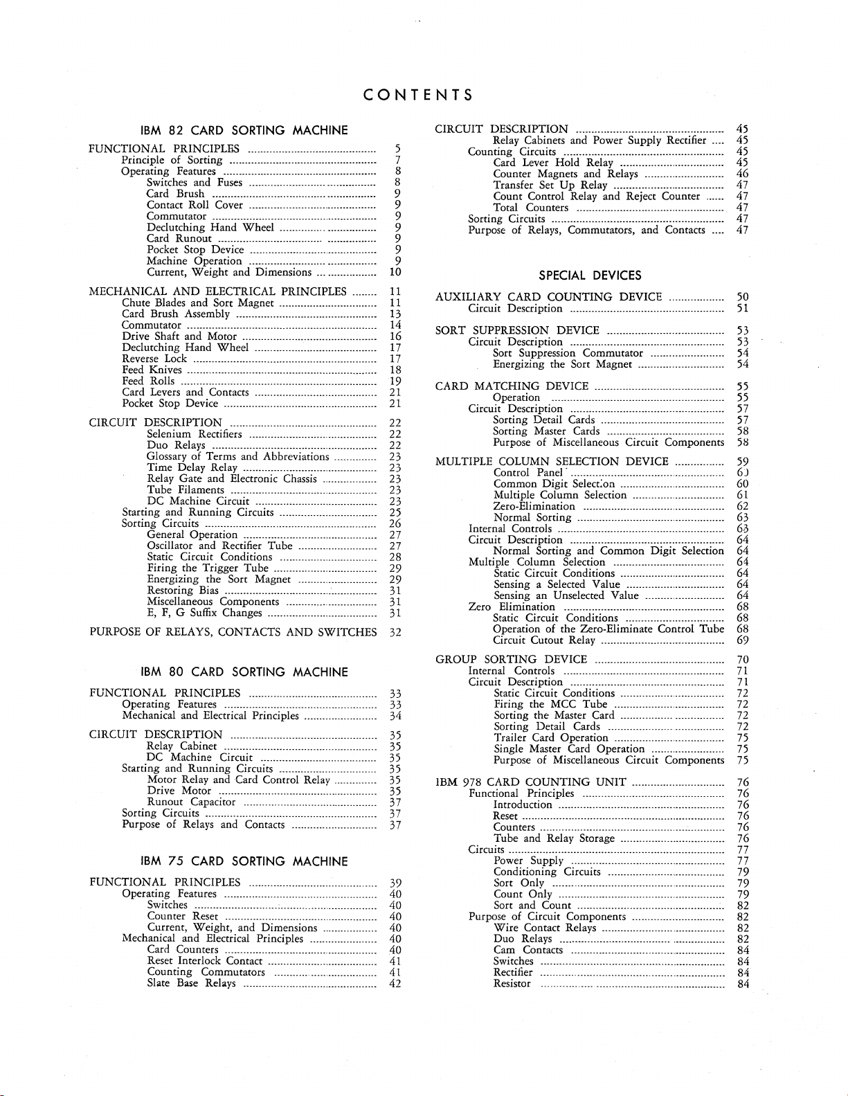
CONTENTS
IBM
82
CARD
SORTING MACHINE
FUNCTIONAL PRINCIPLES .......................................... 5
Principle of Sorting ................................................ 7
Operating Features ........... ....................................... 8
Switches and
Card Brush .................. ................... ................ 9
Contact Roll Cover ....... ............ ....................... 9
Commutator ..................................... ................. 9
Declutching Hand Wheel ............... ................ 9
Card Runout .................................. ................ 9
Pocket Stop Device ......................... .............. ... 9
Machine Operation ......................... ............. ... 9
Current, Weight and Dimensions ... ................
MECHANICAL
Chute Blades and Sort Magnet ......................... .......
Card Brush Assembly ..............................................
Commutator ..............................................................
Drive Shaft and Motor ............................................ 16
Declutching Hand Wheel........................................
Reverse
Feed Knives .............................................................. 18
Feed Rolls ................................................................ 19
Card Levers and Contacts ...... ...... ............................
Pocket Stop Device ................ ................... ........ .......
CIRCUIT DESCRIPTION ................................................
Star~ing
SortIng Circuits ....................... ................................. 26
PURPOSE OF RELAYS, CONTACTS AND SWITCHES
FUNCTIONAL PRINCIPLES ......................................... .
Operating Features ................................................. .
Mechanical and Electrical
CIRCUIT DESCRIPTION ............................................... .
Starting and Running Circuits ............................... .
AND
Lock
Selenium Rectifiers ..........................................
Duo Relays ......................................................
Glossary of Terms and Abbreviations ..............
Time Delay Relay............................................
Relay Gate and Electronic Chassis ...........
Tube Filaments ................................................
DC Machine Circuit ........................................
a!ld
General Operation ............................................
Oscillator and Rectifier Tube ................
Static Circuit Conditions ................................
Firing the Trigger Tube .................................. 29
Energizing the Sort Magnet .......................... 29
Restoring
Miscellaneous Components . ....... ...... ...... ...... ....
E,
F, G Suffix
IBM
80
Relay Cabinet .................................
DC Machine Circuit ..................................... .
Motor Relay and Card Control Relay ............. .
Drive Motor ................................................... .
Sorti~U~~~~ui~a~.~~!.~~.~
Purpose of Relays and Contacts ........................... .
IBM
75
FUNCTIONAL PRINCIPLES .......................................... 39
Operating Features .................................. _...............
Switches ....................... _.................................... 40
Counter Reset ............. ....... ..... ......... ......... ... .... 40
Current, Weight, and Dimensions
Mechanical and Electrical Principles ...................... 40
Card Counters
Reset Interlock Contact ....... ...... ...... .................
Counting Commutators
Slate
Fuses
......................... ... ............. 8
ELECTRICAL PRINCIPLES ........
.................... ........................................
~unning
CARD
CARD
Base
Circuits .. ............... ...............
Bias
.............. ....................................
Changes ....................................
SORTING MACHINE
Principles ....................... .
__
.............. .
..........
~~~~
......
~
........
~~
..................
~~
..
SORTING MACHINE
...
...... ..... .... 40
..
............ ............ ......... ........ ... .... 40
..
Relays ............................................
......... ....... ........ ... ....
_......
...
... ....
::::::::::::::
10
11
11
13
14
17
17
21
21
22
22
22
23
23
23
23
23
25
27
27
28
31
31
31
32
33
33
34
35
35
35
35
35
35
37
37
37
40
41
41
42
CIRCUIT DESCRIPTION ................................................ 45
AUXILIARY CARD
SORT SUPPRESSION DEVICE ......................................
CARD MATCHING
~elay
CountIng Circuits ................................................. ...
Card Lever Hold Relay.................................. 45
Counter Magnets and Relays
Transfer Set
Count Control Relay and Reject Counter ...... 47
Total Counters ................................................ 47
Sorting Circuits ........................................................ 47
Purpose of Relays, Commutators, and Contacts .... 47
Circuit Description ..................................................
Circuit Description ..................................................
Sort Suppression Commutator . ....... ................ 54
Energizing the Sort Magnet ...... ........... ...... ..... 54
Circu?tPg:~~~?Pti~~··::::::::::::::::::::::::::::::::::::::::::::::::::
Sorting Detail Cards . .......... ....... ................. .....
Sorting Master Cards ......................................
Purpose of Miscellaneous Circuit Components
MULTIPLE COLUMN SELECTION DEVICE ................
GROUP SORTING DEVICE .......................................... 70
IBM 978 CARD COUNTING
Control Panel' ..................................................
Common Digit Select:on .................................. 60
Multiple Column Selection ..............................
Zero-Elimination ............................. _................ 62
Normal Sorting ................................................ 63
Internal Controls ......... ...................... ........ ...............
Circuit Description .................................................. 64
Normal Sorting and Common Digit Selection 64
Multiple.
Static
Sensing a Selected
Sensing an Unselected
Zero Elimination ....................... .............. .......... ..... 68
Static Circuit Conditions ................................ 68
Operation of
Circuit Cutout Relay........................................ 69
Internal Controls . ........... ...... ....... ...... ..... ...... ....... ...
Circuit
I?esc~ipti?n
Static
Firing the MCC Tube ....................................
Sorting the Master Card ...............................
Sorting Detail Cards ..................................... 72
Trailer Card Operation ....................................
Single Master Card Operation ........................
Purpose of Miscellaneous Circuit Components
Functional
Introduction . ................ ....... ....... .... ................... 76
Reset .................................................................. 76
Counters ............................................................ 76
Tube and Relay Storage .................................. 76
Circuits ......................................................................
Powe~
ConditiOning
Sort
Count Only...................................................... 79
Sort and Count ..... .................... ..... .................. 82
Purpose of Circuit Components .............................. 82
Wire Contact Relays ............... ......................... 82
Duo Relays ..................................... ................. 82
Cam Contacts ................................................... 84
Switches
Rectifier
Resistor ...... ............ ......... ................................. 84
~abi!lets
Col.umi?'
CirCUit
CirCUit
Principles .............................................. 76
.
Only.......
and Power Supply Rectifier .... 45
..
Up Relay.................................... 47
SPECIAL
COUNTING
DEVICE ..........................................
Supply:
.... ...... ....... .......................... ................. 84
. .... ....... ....... .... ........ ...... ...... .......... ....... 84
DEVICES
Select.i~n
Condltlons ... .......................... ..... 64
Value ................................ 64
.the
Zero-Eliminate Control Tube 68
...... :.:.........................................
Condltlons ..................................
UNIT
..... :........................................... 77
CirCUits
...... ...... ............... ........... 79
................................................. 79
...... .................. 46
DEVICE ..................
.................................... 64
Value .......................... 64
.............................. 76
45
50
51
53
53
55
~~
57
58
51:!
59
6J
61
6.3
71
71
72
72
_.
72
75
75
75
77
Page 5
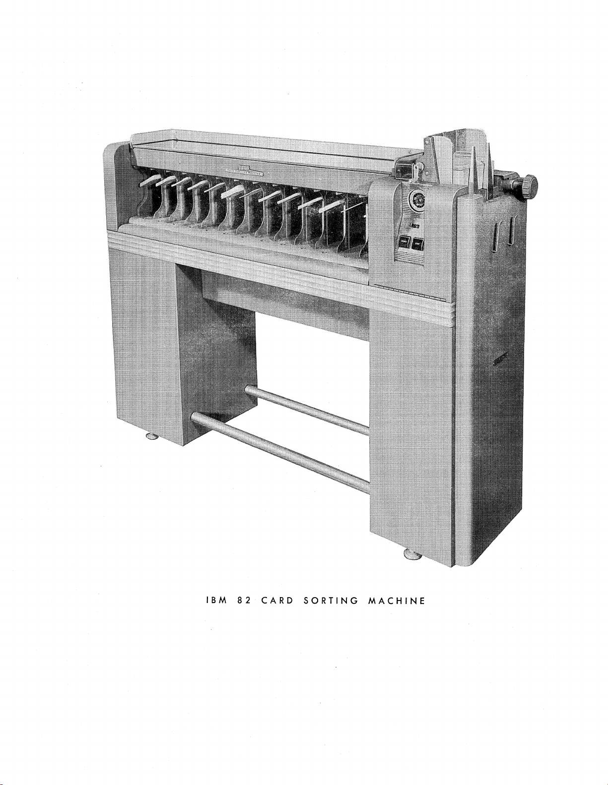
IBM
82
CARD
SORTING
MACHINE
Page 6
IBM
82
CARD
SORTING
MACI-tINI:
FUNCTIONAL
THE THREE machines necessary
operations required in punched card accounting are the
punch, the sorter, and the accounting machine. The
punch establishes the records, the sorter arranges or
classifies them, and the accounting machine produces
the printed reports.
In
punched card accounting systems, thousands of
cards may
final
reports.
be
involved daily in the
In
most
cases,
to
perform the basic
taJSk
of preparing
these cards must
be
classi-
PRINCIPLES
fied
properly prior to the preparation of each report on
accounting machines. Classification of such a large
number of cards manually would present an immense
task which would consume many man hours of work
and would
The Type 82 Card Sorting Machine affords a speedy
and accurate method of arranging cards into
sequence. The
be
greatly subjected to human errors.
operation of the Type 82 Sorter
any desired
is
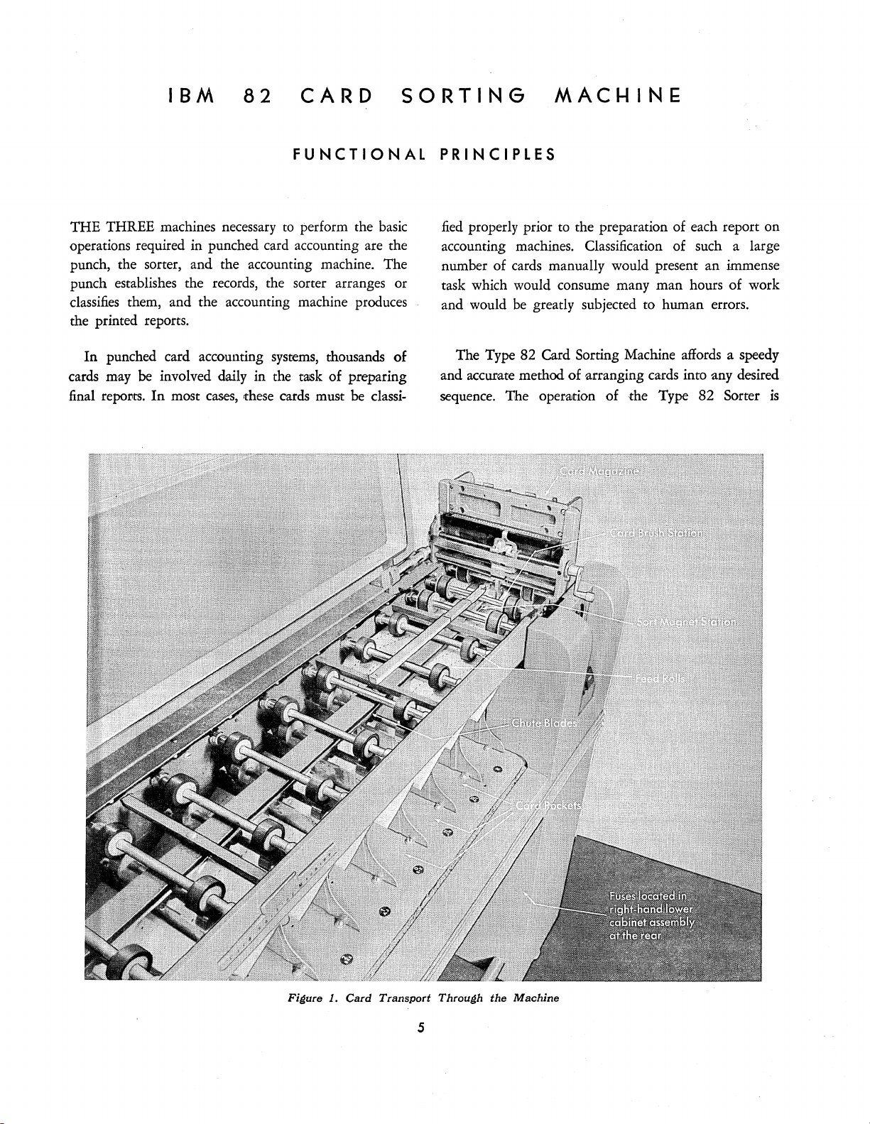
Figure 1. Card Transport Through
the
Machine
Page 7
6
CARD
SORTING
MACHINE,
TYPE
82
entirely automatic, except for the removal and replenishing of cards in the machine.
Sorting cards on the Type 82 machine consists of
running the cards through the machine once for each
is
column in the field being classified. This
comparable
to scanning a series of printed figures with the human
eye, except here an electric sensing brush becomes the
eye.
This brush can sort on only one column at a time.
However, it
tion the brush to sort on
positions on the IBM card. The machine
13
with
each digit value
is
movable,
so
that the operator may posi-
anyone
of the 80 column
is
equipped
pockets for dispersal of cards; one pocket for
0 through
12
and one reject pocket
for cards unpunched in the column being sorted.
By
means of feed knives, cards are
fed
one at a time
from the bottom of the pack in the card magazine on
1).
the right end of the machine (Figure
After leaving
the card magazine, they are gripped between sets of
constantly revolving feed rolls and are fed from the
As
right to the left of the machine.
from right to left, they first
pass
the cards travel
the card brush station,
located between the first and second sets of feed rolls.
Here the punching in the card column being sorted
sensed
by
means of a brush projecting through the holes
is
in the card and making contact on a common roll.
at
Sensing of card punching
the card brush station sets
up the proper combination of raised or lowered chute
blades at the sort magnet station, located between the
is
is
traveling
accom-
to
second and third sets of feed rolls. This setup
as
plished
the leading edge of the card
under the chute blades. The chute blades, according
their setup, then direct the' card
is
(the card
If
a 1 punch
still being carried
is
sensed at the card brush station, the
to
its
proper pocket
by
the feed rolls).
chute blade combination setup will be such that the
If
card will be directed to the 1 pocket.
is
sensed at the card brush station, the chute blade
an 8 punch
combination setup will be such that the card will be
directed to the 8 pocket.
no punching
is
sensed
at
If
the card brush station, all chute blades will remain in
to
a raised position, and the card will be directed
the
reject pocket.
23
13
13
--~
"3" Pocket
12
"2" Pocket
Cards
22
12
22
now
12
22
22
in
order
FIRST
21
"1" Pocket
in
units position
SORT
2
~
112
2 2
3
1
2
1
2 1)
3
1
2 2)
2 1
1
1
1 2
2,2
2 3
2 1
2 2
Cards
in
Magazin
2.
Principle
e
23
23
22
of
Cards
Sorting
22 13
22
22
21
21
21
"2" Pocket
in
order
13
12
12
12
11
"I"
Pocket
in
units and tens position (sub classification)
SECOND
SORT
(in miscellaneous
order)
21
11
21
Figure
g)3
1 3
1
2 3
1 2
2 2
1 2
2 2
1
2 2
2 2
2 1
2 1
1
2
Cards in
order
position
(in
miscellaneous 0
in
tens position)
3
2
1
1
in u
nits
rder
Page 8
FUNCTIONAL
PRINCIPLES
7
During the time that the punching in the card
is
sensed and the proper chute blade combinations are
set up, the card
continually moving from right
to
is
left under control of the constantly running feed rolls.
Speed
cards per minute.
is
Numerical Sorting
and
Capacity
The speed of the Type 82 machine
The
capacity of the card magazine
550 cards.
PRINCIPLE
OF
SORTING
is
650 to 660
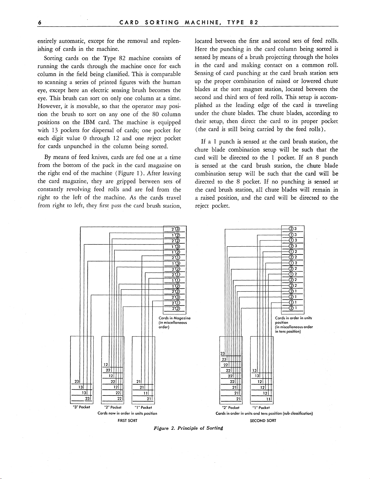
Sorting multiple digit fields when only one column
be
may
sorted
group of cards, punched
at
a time is illustrated in Figure
11
through 23 in a two digit
2.
A
field, are arranged in miscellaneous order and placed
The
in the card magazine of the sorter.
is
sorted first by positioning the card brush
units position
on
that
column and running the cards through the machine.
All cards punched with a 1 in the units column will fall
into the 1 pocket, all cards punched with a 2 in the
units column will fall into the 2 pocket, etc.
When
all the cards have been run through the
machine for sorting on the units position, the card
is
brush
shifted to the tens column position and the
cards removed from the pockets. To remove cards from
l's
the pockets in proper sequence, the
face
first and placed
down in the card magazine, the
are removed
2's are removed next and placed face down on the
l's, the 3's
face
down on the 2's, etc. This
is
common
practice but cards may be removed in descending order
by
starting with the 9's and keeping the cards face up
in the palm of the hand instead of face down. The
important item during removal
is
to keep the cards
in sequence.
After all cards have been removed from the pockets
and replaced in the card magazine, and the card brush
has been located on the tens column position, the
is
machine
restarted and sorting of the tens position
takes place. Those cards punched with a 1 in the tens
position fall into the 1 pocket, the 2's into the 2 pocket,
By
etc.
ing order
removing the cards from the pockets in ascend-
as
was
done on the first sort,
(l's
ahead of
the 2's) the original group of miscellaneous cards will
be
found to be in numerical sequence froni
The sorting process could be illustrated further
the
use
of a larger field, but from the foregoing example
be
it will
observed that, upon completion of the second
11
to 23.
by
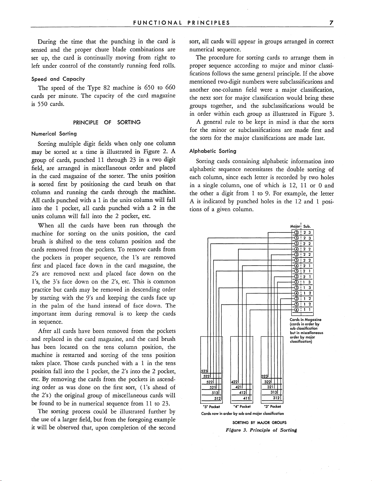
sort, all cards will appear in groups arranged in correct
numerical sequence.
The procedure for sorting cards to arrange them in
proper sequence according to major and minor classi-
If
fications follows the same general principle.
the above
mentioned two-digit numbers were subclassifications and
another one-column field were a major classification,
the next sort for major classification would bring these
groups together, and the subclassifications would be
as
in order within each group
A general rule to be kept in mind
or
for the minor
the
SOrts
for the major classifications are made last.
subclassifications are made first and
illustrated in Figure 3.
is
that the sorts
Alphabetic Sorting
Sorting cards containing alphabetic information into
alphabetic sequence necessitates the double sorting of
is
each column, since each letter
in a single column, one of which
the other a digit from 1 to
is
A
indicated
by
punched holes in the 12 and 1 posi-
recorded by two holes
is
12,
11
or 0 and
9.
For example, the letter
tions of a given column.
Major! Sub
3
3)
! 2
12
5
3
1
5
2
12
4
2
12
12
3
2
1
2
12
4
1
'2
1
1
'2
,
3
1
12
3
: 1
3
i 1
2
: 1
: 1 2
,
, 1
2
1
4Y:
1
Cards
in
Maga
zine
by (cards
in
order
sub
1523
522
522
521
513
"5"
Pocket
Cards now
422 322
512
in
order
SORTING
Figure
421
412
"4"
Pocket
by sub
411
and
major classification
BY
MAJOR
3.
Principie
1323
"3"
321
313
312
Pocket
GROUPS
of
but
order
classification)
Sorting
classificatio
in
miscella
by
major
n
ne~us
Page 9

8
CARD
SORTING
MACHINE,
TYPE
82
The cards are sorted in the normal manner
ing to the digits 1 to 9 in the first column to
zone
The
is
then moved
contact bar on the commutator (Figure
to
the center of the commutator and
the complete sorting operation repeated on the
card column. Positioning the
zone
contact bar in this
accord-
be
sorted.
4)
same
manner suspends sorting for all values of punching
except
pocket will contain the letters A to I
sequence; those in the
and those in the
columns are each sorted in the
the digits 1
punchings
from the pockets following a
cards should be placed
0,
11
and 12. Those
to
0,
cards
which fall in the
in
alphabetic
11
pocket, the letters J
to
° pocket, the letters S to Z. Succeeding
same
9
first,
followed
11
and 12. When cards
face
down
manner
by
sorting of the zone
zone
sort, the
in the card magazine,
are
as
above;
removed
12
12
R;
zone
11
zone
the
cards next; and the °
zone
cards
last in
preparation for digit sorting on the next column.
In
most
cases,
it
is
not necessary to sort on all columns
of a name field to place the cards
in alphabetic order.
Usually sorting on the first three or four characters in
be
a group of names will
OPERATING
REFER
to Figure 4 for the location of the major oper-
sufficient.
FEATURES
ating features.
Switches
and
Fuses
There are 3 operating switches located on the front
right end of the machine. The main line switch, when
turned
on,
furnishes power to the machine and
com-
Fi4ure 4. Operatinl1 Features
Page 10
FUNCTIONAL
PRINCIPLES
.,
pletes a circuit to the filaments of the tubes.
completes a circuit to the time delay relay.
The start button, when depressed, sets up circuits
which energize the drive motor, and it causes the
chine
to
operate. The start button
approximately
line switch because of the delay caused
relay. This delay
filaments to reach proper operating temperature before
the machine
The stop button causes immediate stopping of the
machine.
out feature of the machine
the machine stops
friction.
The fuses are located on the inner side of the right
hand lower cabinet assembly in the position shown in
Figure
Card
may be set on any column to
card brush lifting handle near the front of the card
magazine. Each rotation of the handle moves the brush
one column. The brush may
columns
and sliding the brush holder to the desired column while
pressing down the finger lever at the top of the brush
assembly. A column indicator guide and pointer
located above the brush in a position readily visible
to the operator for convenient setting of the brush on
the column to be sorted.
Contact
before the start key can become operative. This
safety cover which operates two microswitches.
ing of these microswitches when the contact roll cover.
is
Commutator
commutator on which
bar are mounted. The contact bars on the commutator
When
the outside of the commutator, all holes punched in
the card column being sorted are sensed and cause the
card to sort to
1.
Brush
The card brush senses the punching in the card.
The plastic cover. over the contact roll must
raised interrupts the running and sorting circuits.
On
the front end of the first lower
vertical position in the card) and an alphabetic zone
are accessible through the large hole
all of the commutator contact bars are toward
50 seconds after turning on the main
is
necessary to allow the electron tube
is
started.
When
by
Roll
the
stOP
button
is
rendered inoperative, and
as
soon
as
its inertia
be
be
rotating the handle to the upper position
Cover
12
contact bars (one for each
its proper pocket. However,
is
ineffective for
by
the time delay
is
depressed, the run-
is
sorted
by
moved across several
in
the switch plate.
It
overcome
rotating the
be
down
Open-
feed
roll
if
the 4 and
also
ma-
by
It
is
is
is
o contact bars, for example, were moved to the center
of the commutator, sorting of 4's and
suspended. Any 4 or
being sorted would not be sensed and the card would
feed
to the reject pocket just
punched. Sorting of all other digits would be normal.
1£
the zone contact bar (red bar)
center of the commutator, sorting will be suspended
for all punching except
cards that have no
being sorted, will be fed to the reject pocket
they were unpunched.
Declutching Hand Wheel
A declutching hand wheel
the machine over
timings. This hand wheel
of the machine and, when rotated in a clockwise
tion, causes the main drive shaft and its gears to revolve.
The handwheel must be pressed
is
being revolved before the main worm shaft will
rotate.
the handwheel
it from revolving and presenting a hazard.
Card Runout
machine
in the machine keeps the drive motor running for a
long enough period of time to allow all cards to feed
to
runout feature was not present, making it necessary in
many cases to depress the start
the last
a
matic pocket stop. This
matically shuts
when
capacity with cards. Each pocket has a capacity of
a
Machine Operation
When
When
their proper pockets.
Pocket Stop Device
Each pocket of the sorter
anyone
approximately
stopped
can not be restarted
the full pocket or pockets have been emptied.
The main line switch should be turned on first to
allow time for the tubes to heat up while other
tions for starting are
the machine
the card magazine becomes empty while the
is
in operation, a runout feature incorporated
few
cards into their proper pockets.
of the thirteen pockets becomes filled to
by
the activation
0 punching in the card column
as
0,
11
and 12.
0,
11
or
12
punching in the column
is
provided for turning
by
hand to check adjustments and
is
located on the right end
is
operating under power,
is
automatically declutched to keep
On
older sorting machines
key
is
equipped with an auto-
is
a safety device which auto-
off
the current and stops the machine
550 cards. Once the machine has been
of
the pocket stop device, it
by
means of the start key until
being
completed.
O's
though it were un-
is
moved to the
That
to
the left while
long enough to feed
would be
is,
those
as
though
direc-
it
this
prepara-
Page 11

10
Prior
CARD
to
placing cards in the card magazine, they
SORTING
should be carefully joggled against the glass top frame.
Cards are then inserted in the
the 9 edge to the left.
into the magazine. Check to
magazIne,
Do
not drop or force the cards
see
face
down with
that the edges of the
cards are even to assure free movement within the
magazine. Place the card weight on top of the pack
to insure proper feeding
of
the last
few
cards.
After the cards have been placed in the card maga-
zine, the card brush should
be
positioned on the proper
, card column. The contact bars on the commutator
should
or
the card column will be sensed
contact roll cover must be down before the start
be
checked to
OUT
position if desired,
see
that they are in the contacting
so
that all holes punched in
by
the card brush. The
key
can become operative.
Assuming that all of the above conditions have been
satisfied, the start
machine
to
key
may
be
depressed to cause the
operate. This key must be held depressed
until the cards have reached the third set of upper feed
rolls, thus dosing all card lever contacts. Once cards
have reached this position in the machine, it will continue
to
operate automatically until the card magazine
has been emptied of cards, one or more pockets become
full, or the stop
key
is
depressed. The contact roll cover
MACHINE,
must not
since this may
TYPE
be
raised while the machine
cause
82
mis-sorting
is
in operation
as
the machine comes
to a stop.
Care should be exercised when adding
card magazine while
the machine
is
jar the pack of cards already present in
and do not add any
in the machine
the machine
Current,
See
current and
NOTE:
Y2
HP
In
the
under the
to
Weight,
the table below for the operating current, starting
fuse
Some Type 82 machines were produced using
motors equipped with fusetrons instead of
case
of these machines,
1/3
cards jf the pack of cards present
is
small; either procedure may cause
jam.
and
Dimensions
rating of the Type
-the
fusetron racing listed
HP
heading may be used
cards to the
operating. Do not
the machine
82
machine.
as
these values
give enough safety factor due to their time lag char-
aoreristJic.
Weight unpacked Weight packed
Length
Width
Height - - - - - - -
530 pounds
785
pounds
61
inches
16
inches
46 inches
fuses.
----
Voltage Group
Volts
115
230
115
115 50
115
230
230 50
230 60 1 3.7 3.5
208 60
230 25
230 50
230 60
Cycles
DC
DC 3.0
25
60
25
Phases
1
1
1
1 3.7
1
1
3
3
3
Maximum
Operating Current
Amperes
1/2
HP
5.0
6.5
7.0 6.5
6.5
4.0
4.0 3.8
2.1
2.3 2.2
2.1 2.0
1/3
5.0
3.0
6.0
6.1
3.5
3.9
2.0
HP
Maximum
Starting Current
Amperes
1/2
HP
42.9 36.9
21.9
38.9
37.9
39.9
18.6
19.1 13.0
20.1
18.2
12.7
14.6
13.2
1/3
18.9
26.7
25.6
26.9
13.5
15.0
16.6
8.4
9.9
9.1
HP
Main
Fuses
Ampere Rating
1/2
HP
Fuse
12
6
12
12
12
6 4.0
6 4.0
6
6
6 2.5
6 2.5
6
1/3
HP
Fusetron
5.0
3.2
8.0
8.0
8.0
4.0
4.0
2.5
Page 12
MECHANICAL
THE
REAR cover assembly and the covers on the right
AND
and left ends of the machine are each held in place
by
means of concealed latches. These latches may
released
bottom and held in place
by
pressing on the latch cover plate.
The cover over the switch plate
by
a holding screw at the
is
hinged at the
be
upper right hand corner. The right end cover must
is
be removed before this holding screw
accessible.
ELECTRICAL
PRINCIPLES
sort magnet armature. There are two styles of chute
use.
blades in
the new style blade
The old style blade
is
.009" thick. The .009" blade
has better wearing qualities than the
Each blade
which it guides the card.
is
numbered according to the pocket to
In
is
.008" thick and
.008" blade.
guiding a card to the
proper pocket, the card rides immediately over the
chute blade for that pocket.
Four adjustable levelers are furnished with each
machine for the purpose of leveling the machine and
to eliminate excessive vibration caused
by
an uneven
floor surface.
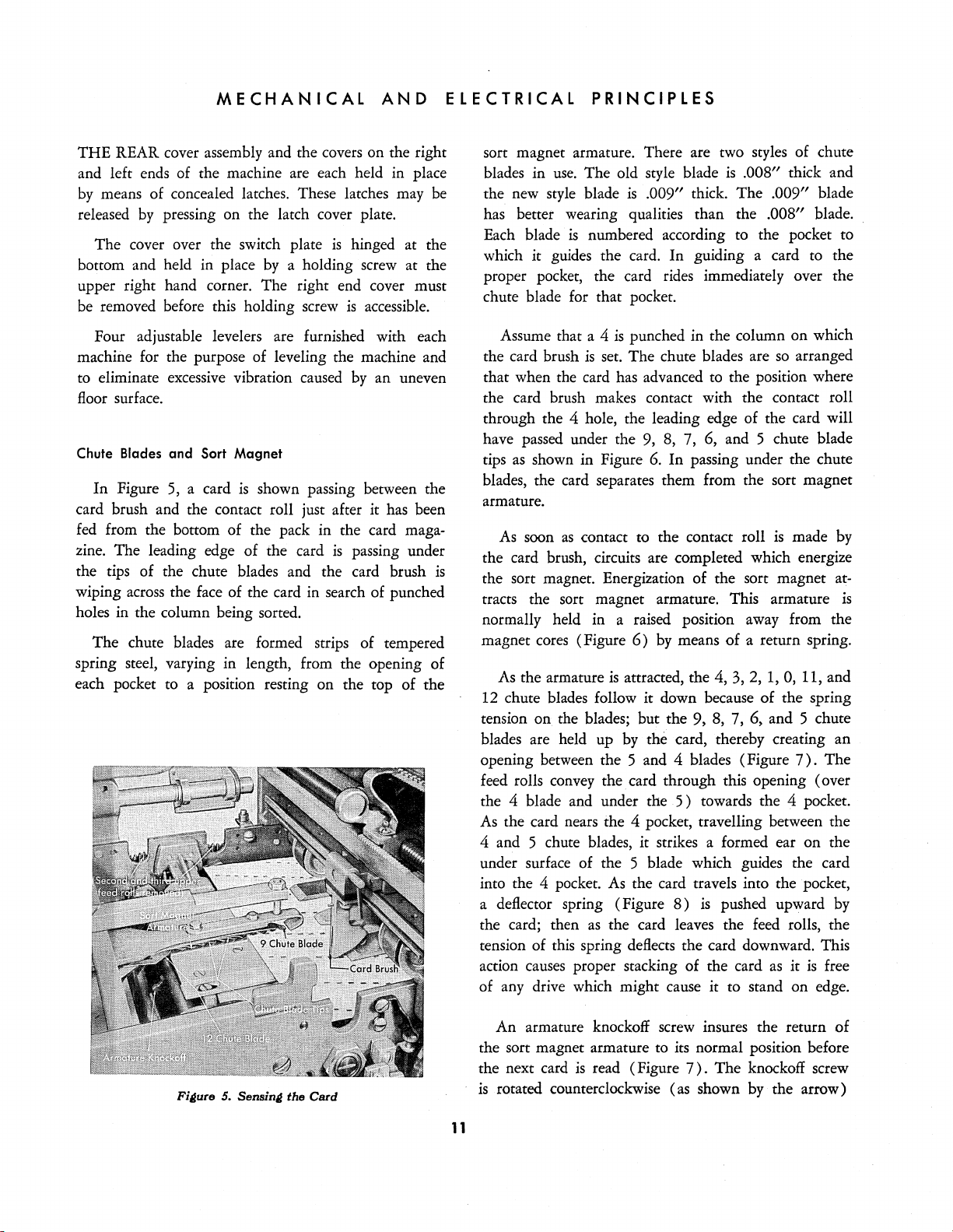
Chute Blades
In
Figure 5, a card
and
Sort
Magnet
is
shown passing between the
card brush and the contact roll just after it has been
fed
from the bottom of the pack in the card magazine. The leading edge of the card
the tips of the chute blades and the card brush
is
passing under
is
wiping across the face of the card in search of punched
holes in the column being sorted.
The
chute blades are formed strips of tempered
spring steel, varying in length, from the opening of
each pocket to a position resting on the top of the
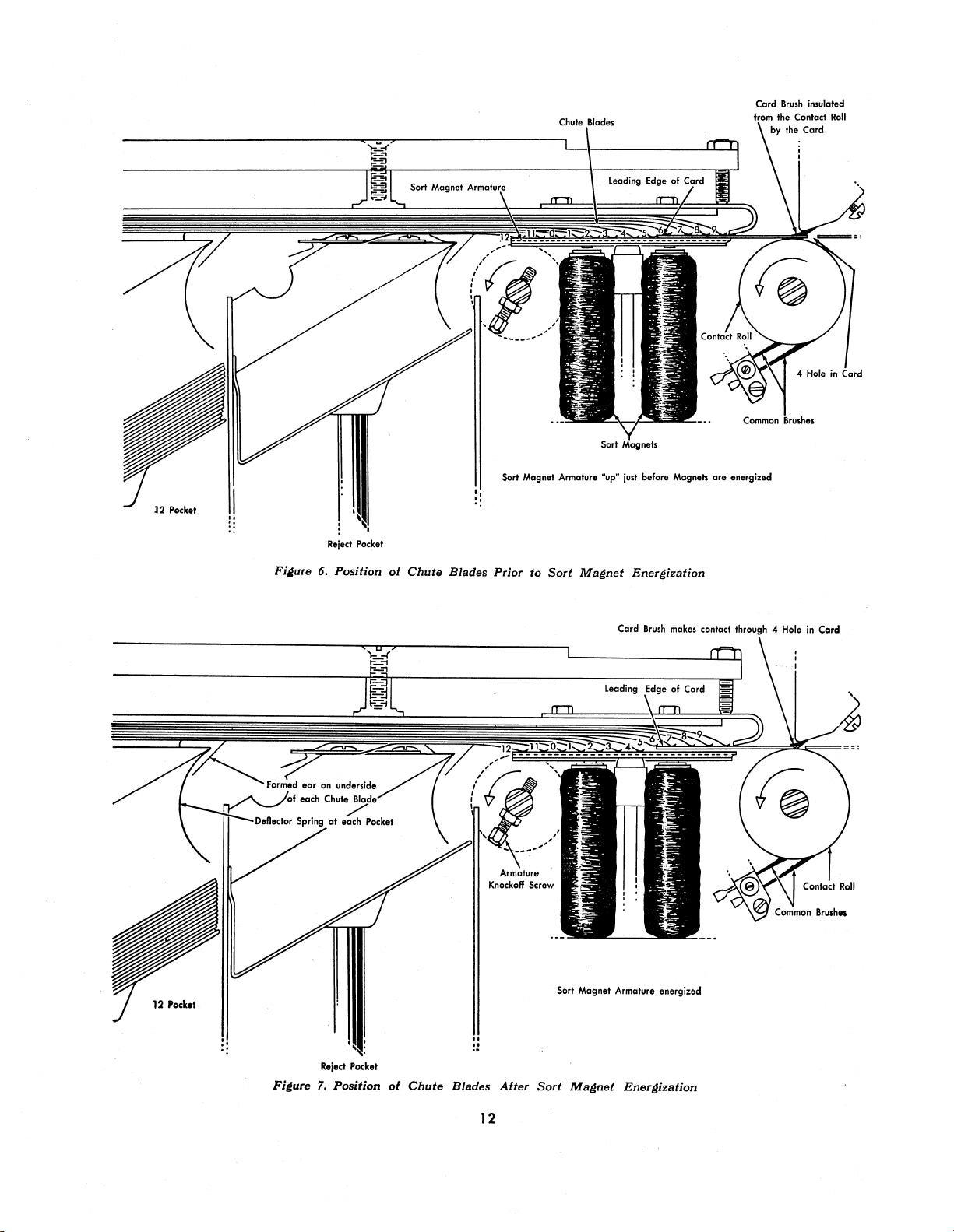
Assume that a 4
the card brush
is
punched in the column on which
is
set. The chute blades are
so
arranged
that when the card has advanced to the position where
the card brush makes contact with the contact roll
through the 4 hole, the leading edge of the card will
have passed under the 9, 8, 7, 6, and 5 chute blade
tips
as
shown in Figure
6.
In
passing under the chute
blades, the card separates them from the sort magnet
armature.
As
soon
as
contact
to
the contact roll
is
made
by
the card brush, circuits are completed which energize
the sort magnet. Energization of the sort magnet attracts the sort magnet armature. This armature
normally held in a raised position away from the
magnet cores (Figure
As the armature
is
means
attracted, the 4,
of
a return spring.
3,2,
1,
0,
11, and
6)
by
12 chute blades follow it down because of the spring
on
tension
the blades; but the 9, 8, 7, 6, and 5 chute
blades are held up by the card, thereby creating an
opening between the 5 and 4 blades (Figure
7).
The
feed rolls convey the card through this opening (over
the 4 blade and under the
As
the card nears the 4 pocket, travelling between the
5)
towards the 4 pocket.
4 and 5 chute blades, it strikes a formed ear on the
under surface of the 5 blade which guides the card
As
into the 4 pocket.
a deflector spring (Figure
the card; then
the card travels into the pocket,
8)
is
pushed upward by
as
the card leaves the feed rolls, the
tension of this spring deflects the card downward. This
action causes proper stacking of the card
as
it
is
free
of any drive which might cause it to stand on edge.
is
Fi~ure
5.
Sensin~
the
Card
An armature knockoff screw insures the return of
the sort magnet armature to its normal position before
is
the next card
is
rotated counterclockwise (as shown by the arrow)
11
read (Figure
7).
The
knockoff screw
Page 13
12
Pock.t
Reject
Pocket
','
"
"
Sort
Magnet Armatur.
·up·
just
before Magne
..
are
Card
energized
Brush
insulated
12
Pock.t
Fi~ure
6, Position
of
Chute
Blades Prior to
Sort
Magnet
Sort Magnet Armature energized
Energization
" Hole
in
Card
Figure
Reject
'1,
Position
Pock.t
of
Chute
Blades
12
After
Sort
Magnet
Enerl1ization
Page 14
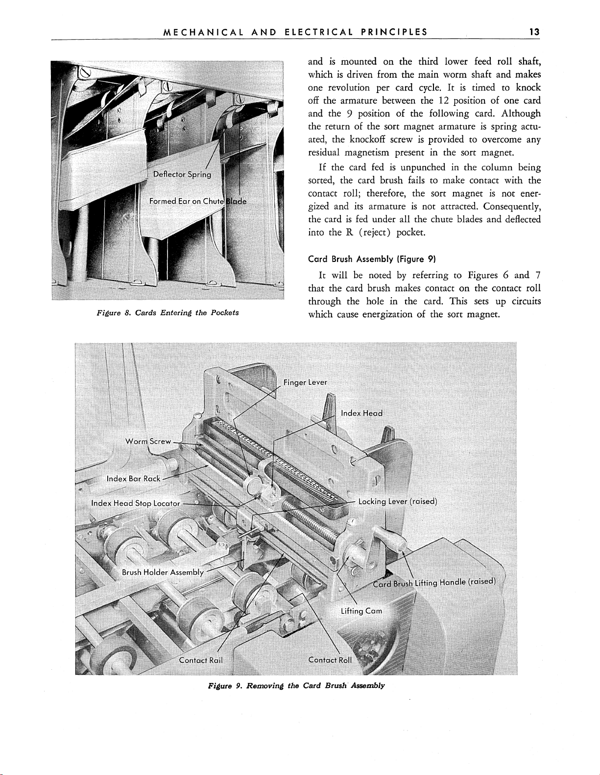
Figure 8.
MECHANICAL
Cards
Entering the Pockets
AND
ELECTRICAL
and
is
which
one revolution per card cycle.
off
the armature between the
PRINCIPLES
mounted on the third lower feed roll shaft,
is
driven from the main worm shaft and makes
It
is
timed
12
position of one card
and the 9 position of the following card. Although
the return of the sort magnet armature
is
ated, the knockoff screw
provided to overcome any
is
residual magnetism present in the sort magnet.
If
the card fed
sorted, the card brush fails
contact roll; therefore, the sort magnet
is
its
fed
gized and
the card
is
unpunched in the column being
to
make contact with the
is
armature
is
not attracted. Consequently,
under all the chute blades and deflected
into the R (reject) pocket.
Card
Brush
It
Assembly (Figure
will
be
noted
by
9)
referring to Figures 6 and 7
that the card brush makes contact on the contact roll
through the hole in the card. This sets up circuits
which cause energization of the sort magnet.
13
to
knock
spring actu-
not ener-
Figure 9.
Removing
the Card Brush' Assembly
Page 15
14
CARD
SORTING
MACHINE,
TYPE
82
The card brush· may be positioned at
any
column
desired through manual operation of the card brush
lifting handle and the finger lever on the index head
rack holder (Figure
it
is
necessary that the card brush lifting handle be
in a position with
4).
During a sorting operation,
its
handle downward,
as
this allows
the card brush to rest on the contact roll for the pur-
pose of reading the card.
When
the card brush lifting handle
is
rotated one-
half turn from its normal downward position, the
card brush assembly
by
means of a cam pinned on each end of the worm
screw ( Figure
to raise the worm
held down
by
is
raised clear of the contact roll
9).
These
screw.
cams
operate against rollers
The worm
screw
is
normally
means of a compression spring on each
end.
Rotation of the card brush lifting handle one-half
turn not only raises the brush to clear the contact
roll, but also disengages the index head stop locator
from the index bar rack. This
assembly
is
to be moved. For one column movement,
one complete revolution of the lifting handle
is
necessary if the brush
raises
the
brush, disengages the index head stop locator, moves the
brush one column through the lead of the worm, and
lowers the brush to the contact roll
as
the index head
stop locator seats in the adjacent index bar rack tooth.
Rotation of the card brush lifting handle in a clockwise
direction moves the brush toward the rear of
the machine. Rotation of the handle counterclockwise
moves the brush toward the front of the machine.
To move the card brush assembly a distance of
several columns or more, the lifting handle
one-half turn to
its
raised position.
As
is
rotated
stated above,
this raises the brush from the contact roll and disengages the index head stop locator from the rack.
By
depressing the finger lever on the index head rack
holder, the index head locating nut
from the worm
screw.
This
is
mally held engaged with the worm screw
is
then disengaged
a half nut and
by
is
nor-
means of
a spring. Disengaging the index head locating nut
from the worm screw allows free movement, in either
direction, of the complete index head and brush holder
assemblies
the desired movement has been completed again
gages the locating nut with the worm
returning the lifting handle to
as
a unit. Releasing the finger lever after
screw,
its
downward position
en-
and
readies the brush for sensing the card.
Brush
Block
l!Iongated
Holes
Here
Brush
Holder
Brush
_----1-
F;~ure
10. Card
Brush
Holder
Assembly
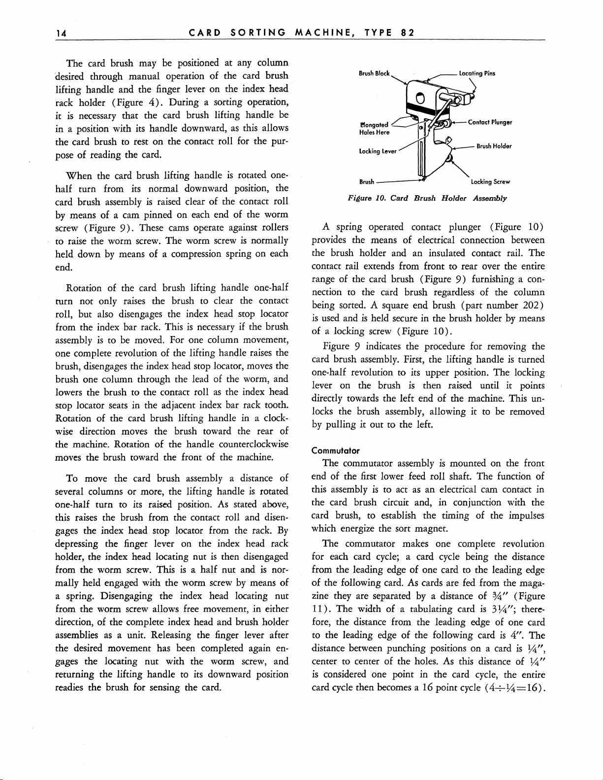
A spring operated contact plunger (Figure 10)
provides the means of electrical connection between
the brush holder and an insulated contact rail. The
contact rail extends from front to rear over the entire
range of the card brush (Figure
nection
to
the card brush regardless of the column
9)
furnishing a con-
being sorted. A square end brush (part number 202)
is
used
and
is
held secure in the brush holder
of a locking screw (Figure
10).
by
means
Figure 9 indicates the procedure for removing the
card brush assembly. First, the lifting handle
one-half revolution to
lever on the brush
its
upper position. The locking
is
then raised until it points
is
turned
directly towards the left end of the machine. This unlocks the brush assembly, allowing it
by
pulling it out to the left.
Commutator
The commutator assembly
is
mounted on the front
to
be removed
end of the first lower feed roll shaft. The function of
this assembly
is
to act
as
an electrical cam contact in
the card brush circuit and, in conjunction with the
card brush, to establish the timing of the impulses
which energize the sort magnet.
The commutator makes one complete revolution
for each card cycle; a card cycle being the distance
from the leading edge of one card to the leading edge
of the following card.
zine they are separated
11
).
The width of a tabulating card
As
cards are
by
a distance of
fed
from the maga-
%"
is
3
~";
(Figure
there-
fore, the distance from the leading edge of one card
to the leading edge of the following card
distance between punching positions on a card
center to center of the holes.
is
considered one point in the card cycle, the entire
As
this distance of
card cycle then becomes a 16 point cycle
(4-7-
is
~
4".
The
is
~",
~"
= 16) .
Page 16
MECHANICAL
AND
ELECTRICAL
PRINCIPLES
15
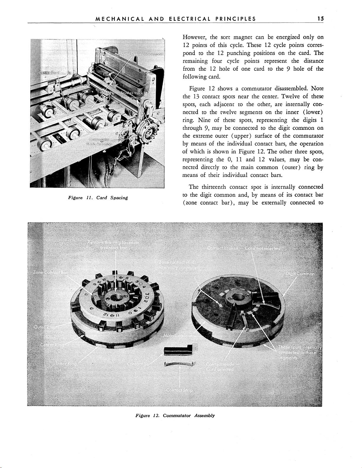
Fillure 11. Card Spacing
However, the sort magnet can
12 points of this cycle. These 12 cycle points
pond
to
the 12 punching positions on the card. The
be
energized only on
corres-
remaining four cycle points represent the distance
from the
hole of one card
to
the 9 hole of the
12
following card.
12
Figure
13
the
spots, each adjacent to the other, are internally
nected
shows a commutator disassembled. Note
contact spots near the center. Twelve of these
con-
to
the twelve segments on the inner (lower)
ring. Nine of these spots, representing the digits 1
to
through 9, may be connected
the digit common on
the extreme outer (upper) surface of the commutator
by
means of the individual contact bars, the operation
is
of which
shown
representing the
nected directly to the main common (outer) ring
in
Figure 12. 'The other three spots,
0,
11
and
12
values, may be con-
by
means of their individual contact bars.
is
The thirteenth contact spot
to
the digit common and,
bar),
(zone contact
maybe
by
internally connected
means of its contact bar
externally connected to
Figure 12.
Commutator
Assembly
Page 17
16
CARD
SORTING
MACHINE,
TYPE
82
the main (outer) common ring. Note that
contact bar
mon
is
in its retracted position, the digit com-
is
not connected
to
the main common.
if
the zone
By
re-
tracting the zone contact bar, sorting of all digit values
1 through 9
is
suspended and only 0, 11, and 12 values
are sorted.
There are three division points
on
the periphery
of
the commutator; the inner, center, and outer rings.
Three contact brushes ride on this periphery, one to
contact each ring (Figure
sists of
12
insulated segments corresponding to each
11).
The inner ring con-
value in the card and internally connected to the 12
contact spots
is
timed to the machine in such a manner that, when
as
mentioned above. The commutator
the card brush makes through the 4 hole in the card
for example, the inner commutator brush will be mak-
ing contact
on
the 4 segment. The center and outer
rings are commoned together. The outer (common)
ring extends around the complete circumference
of
the commutator. The center ring extends around
approximately three fourths of the commutator circumference; the other one fourth
When
the
OA4G
a hole
is
trigger tube
sensed in the card, a circuit
is
first completed through the
is
insulation.
to
fire
commutator from one of the 12 segments on the inner
ring to the outer
or
common ring through the commutator contact brushes and the contact bar for that
position.
As
soon as the trigger tube has been fired, a
holding circuit
completed from the center brush
Firing the trigger tube removes the negative bias
to
maintain conduction in the tube
to
the outer brush.
is
on
the sort magnet control tubes and allows them to
energize the
maintain conduction
SOrt
magnet. Furnishing a hold circuit to
in
the trigger tube keeps the sort
magnet energized until the center brush breaks contact
on
the center ring. This occurs after the 12
position on the card has passed under the card
brush, thus completing the sensing of any holes
in
that card column.
If
two holes are present in a column being sensed,
and no provisions are made by means of the contact
bars
on
the commutator to suspend sorting
of
one
value, the card will sort according to the first value
sensed by the brush.
When
the reading brush
tact roll between cards, no circuit
is
resting on the bare con-
is
available to fire
the trigger tube because both the inner and center
commutator brushes are
on
insulated portions
of
the
commutator.
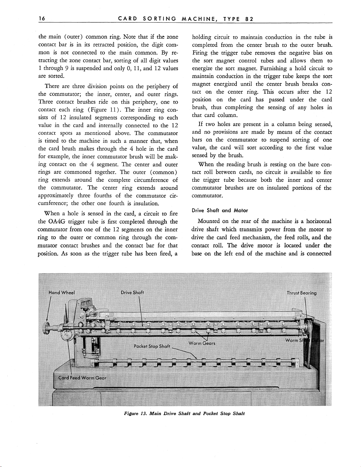
Drive Shaft and
Mounted
Motor
on
the rear of the machine
is
a horizontal
drive shaft which transmits power from the motor to
drive the card feed mechanism, the feed rolls, and the
contaot roll.
base
on
The
drive motor is
the left end
of
the machine and
10C3Jted
is
under the
connected
Figure
13.
Main
Drive
Shaft
and
Pocket
Stop
Shaft
Page 18
MECHANICAL
AND
ELECTRICAL
PRINCIPLES
17
to the drive shaft
Variations in machine speed are obtained
by
means of a V belt and pulleys.
by
adjusting
the variable speed pulley on the drive motor. The
motor mounting
is
adjustable vertically and can be
pivoted in an arc for the purpose of regulating belt
tension and alignment. The complete motor and
mounting assembly
is
easily removed for repair or
renewal.
The drive shaft extends over the length of the
machine approximately on a level with the card line
(Figure
are used for the purpose of gearing to the
13).
Worms cut at intervals on the shaft
feed
roll
shafts, which run at right angles to the drive shaft.
Except for the first 3
sets
of feed rolls, only the lower
feed rolls are gear driven; the upper rolls are friction
driven from the lower rolls. Located at the right end
of the drive shaft (rear view)
is
a thrust bearing which
aids in absorbing the thrust developed in the shaft.
This bearing must be kept well lubricated.
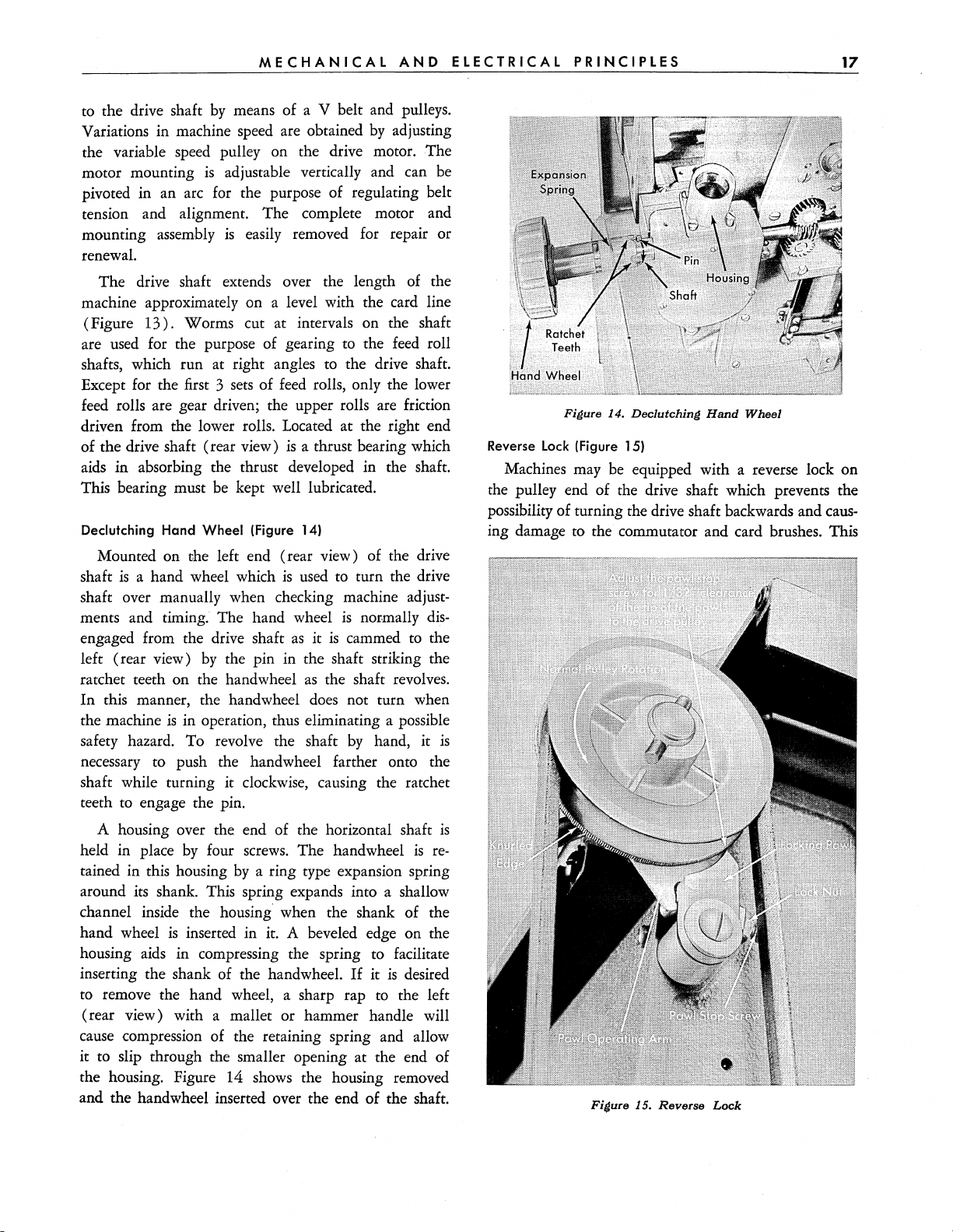
Declutching Hand Wheel (Figure 14)
Mounted on the left end (rear view) of the drive
shaft
is
a hand wheel which
is
used
to turn the drive
shaft over manually when checking machine adjustments and timing. The hand wheel
engaged from the drive shaft
left (rear view)
by
the pin in the shaft striking the
as
ratchet teeth on the handwheel
In
this manner, the handwheel
the machine
is
in operation, thus eliminating a possible
safety hazard. To revolve the shaft
is
normally
it
is
cammed
as
the shaft revolves.
does
not turn when
by
hand, it
to
dis-
the
is
necessary to push the handwheel farther onto the
shaft while turning it clockwise, causing the ratchet
teeth to engage the pin.
Figure 14.
Reverse Lock (Figure 15)
Declutching
Hand
Wheel
Machines may be equipped with a reverse lock on
the pulley end of the drive shaft which prevents the
possibility of turning the drive shaft backwards and
caus-
ing damage to the commutator and card brushes. This
A housing over the end of the horizontal shaft
held in place
tained in this housing
by
four
screws.
by
The handwheel
a ring type expansion spring
is
re-
around its shank. This spring expands into a shallow
channel inside the housing when the shank of the
hand wheel
housing
inserting the shank of the handwheel.
is
inserted in it. A beveled edge on the
aids
in compressing the spring to facilitate
If
it
is
desired
to remove the hand wheel, a sharp rap to the left
(rear view) with a mallet or hammer handle will
cause compression of the retaining spring and allow
it to slip through the smaller opening at the end of
the housing. Figure 14 shows the housing removed
and the handwheel inserted over the end
of
the shaft.
is
Figure 15.
Reverse
Lock
Page 19
18
CARD
SORTING
MACHINE,
TYPE
82
reverse lock
is
in the form of a ratchet knurl cut on the
rim of the drive pulley. A locking pawl operates against
is
the pulley when the force of motion
direction (viewed from the pulley
any actual rotation of the pulley.
is
rotation
end),
counterclockwise (viewed from the pulley
the locking pawl
is
held away from the knurled
end),
When
in a clockwise
thus preventing
the direction of
edge through the action of the pawl operating arm.
The pawl operating arm
actuated
by
a friction contact
is
with the drive pulley. The knurled teeth on the rim
of
the pulley are fine enough to prevent any appre-
ciable motion when the reverse lock operates. Any older
80 machines which are not equipped with the
Type
declutching type of handwheel should have a reverse
lock mechanism.
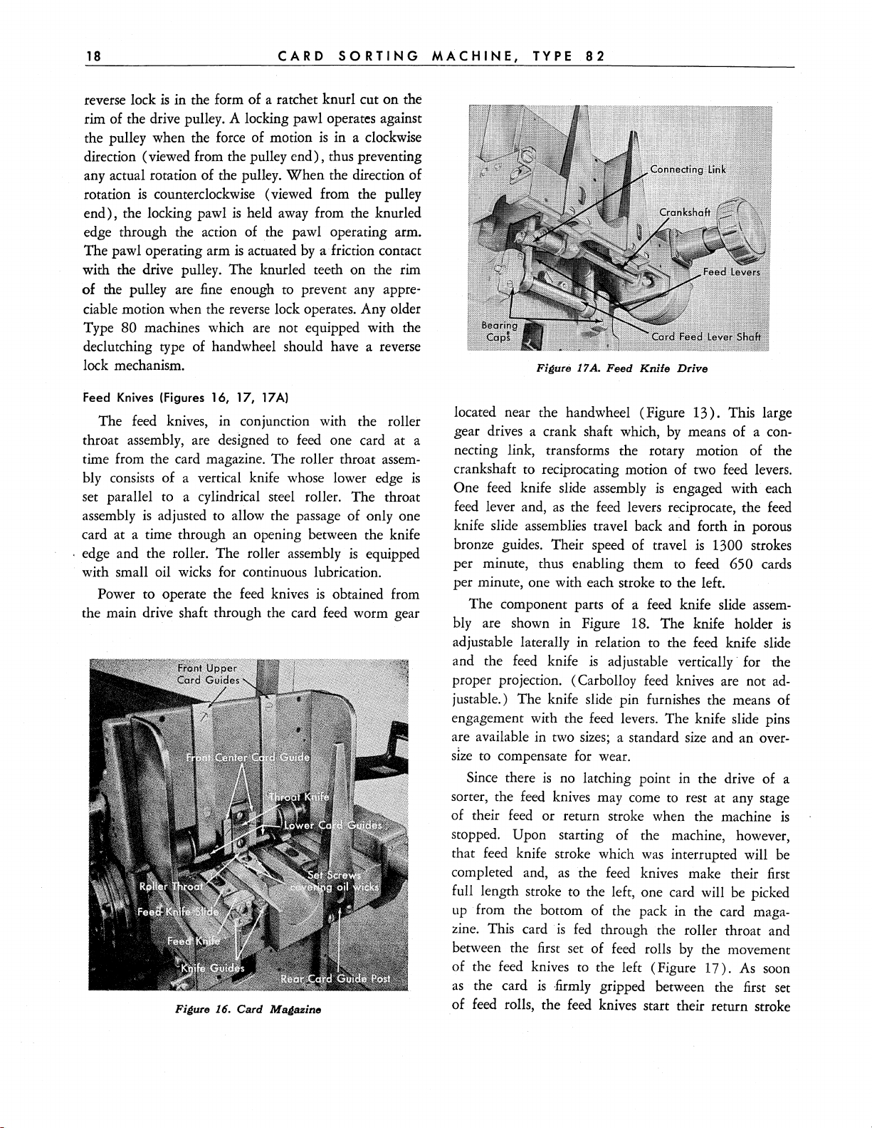
Feed
Knives
The
(Figures 16, 17, 17A)
feed
knives, in conjunction with the roller
throat assembly, are designed to feed one card at a
time from the card magazine. The roller throat
assem-
bly consists of a vertical knife whose lower edge
set parallel
assembly
to
a cylindrical steel roller. The throat
is
adjusted to allow the passage of only one
card at a time through an opening between the knife
is
. edge and the roller. The roller assembly
equipped
with small oil wicks for continuous lubrication.
feed
Power to operate the
knives
the main drive shaft through the card
Figure
16.
Card
Magazine
is
obtained from
feed
worm gear
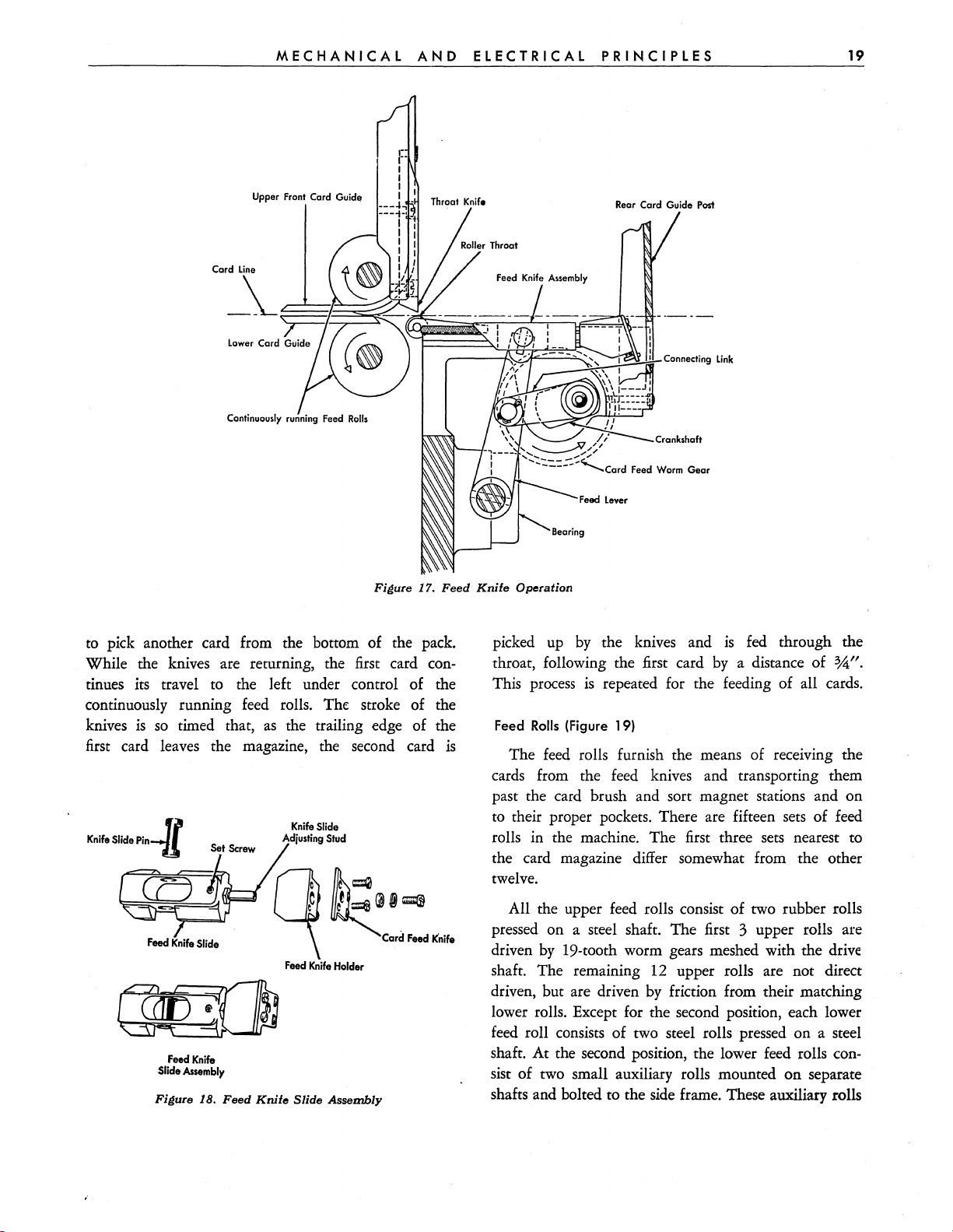
Figure
17A.
Feed
Knife
Drive
located near the handwheel (Figure
gear drives a crank shaft which,
13).
by
means of a con-
necting link, transforms the rotary motion of the
crankshaft to reciprocating motion of two feed levers.
is
One feed knife slide assembly
feed
lever and,
as
the
feed
is
engaged with each
levers reciprocate, the
knife slide assemblies travel back and forth in porous
bronze guides. Their speed of travel
is
per minute, thus enabling them to feed
per minute, one with each stroke to the left.
The component parts of
a feed knife slide
bly are shown in Figure 18. The knife holder
adjustable laterally in relation to the feed knife slide
feed
knife
is
and the
proper projection. (Carbolloy
adjustable vertically' for the
feed
knives are not
justable.) The knife slide pin furnishes the means of
engagement with the feed levers. The knife slide pins
are available in two
SIze
to
compensate for wear.
Since there
sorter, the
of their
is
no latching point in the drive of a
feed
knives may come to rest at any stage
feed
or return stroke when the machine
a standard
size
sizes;
stopped. Upon starting of the machine, however,
feed
that
knife stroke which
completed and,
as
the
was
interrupted will
feed
knives make their first
full length stroke to the left, one card will be picked
up
from the bottom of the pack in the card maga-
zine. This card
between the first set of
is
fed
through the roller throat and
feed
rolls
by
the movement
of the feed knives to the left (Figure
as
the card
feed
of
is
rolls, the
·firmly
feed
gripped between the first set
knives start their return stroke
This large
1300 strokes
650 cards
assem-
and an over-
17).
As
soon
feed
is
ad-
is
be
Page 20
MECHANICAL
AND
ELECTRICAL
PRINCIPLES
19
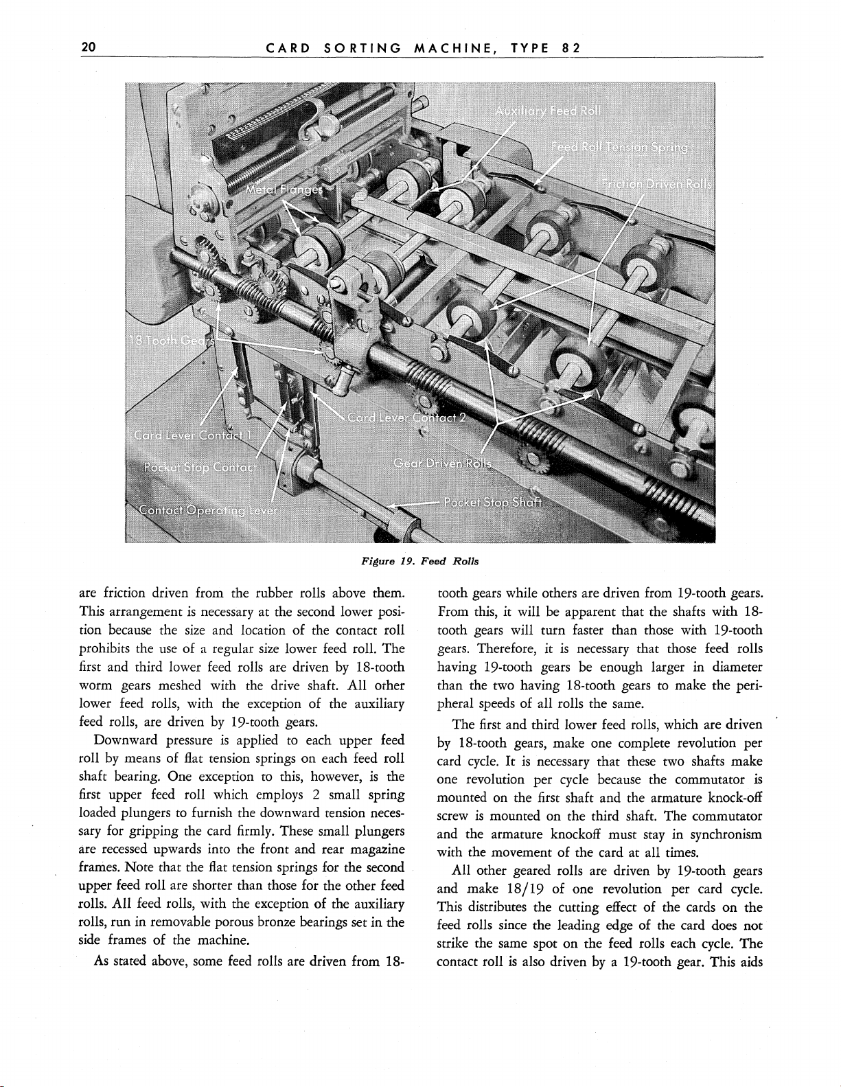
Upper Front Card Guid"
Continuou.ly running Feed
to
pick another card from the bottom of the pack.
While the knives are returning, the
RollI
Fi~ure
first
Throat
17.
card con-
Feed
tinues its travel to the left under control of the
continuously running
knives
first
is
so
timed that,
card leaves the magazine, the second card
Feed
Knife
Slide Assembly
Fi~ure
18.
Feed
feed
rolls. The stroke of the
as
the trailing edge of the
Knife
Slide
Adjulting
Stud
~~~
cO
~j~
~
Feed
Knife
Holder
Knife
Slide
Assembly
Card
Feed
is
Knife
Knife
__
Knife
Operation
picked
throat, following the first card
This
Feed
The
up
process
Rolls
(Figure 19)
feed
Rear Card Guide Post
J«---t-l1
by
the knives and
is
repeated for the feeding of all cards.
Connecting
Link
is
fed through the
by
a distance of
rolls furnish the means of recelvmg the
cards from the feed knives and transporting them
past the card brush and sort magnet stations and on
to their proper pockets. There are fifteen sets of feed
rolls in the machine. The
first
three sets nearest to
the card magazine differ somewhat from the other
twelve.
All the upper
feed
rolls consist of two rubber rolls
pressed on a steel shaft. The first 3 upper rolls are
driven
shaft. The remaining
driven, but are driven
by
19-tooth worm gears meshed with the drive
12
upper rolls are not direct
by
friction from their matching
lower rolls. Except for the second position, each lower
feed
roll consists of two steel rolls pressed on a steel
shafr. At the second position, the lower feed rolls consist of two small auxiliary rolls mounted
on
shafrs and bolted to the side frame. These auxiliary rolls
%0".
separate
Page 21
20
CARD
SO
RTING
MACHINE,
TYPE
8-=2
_________
_
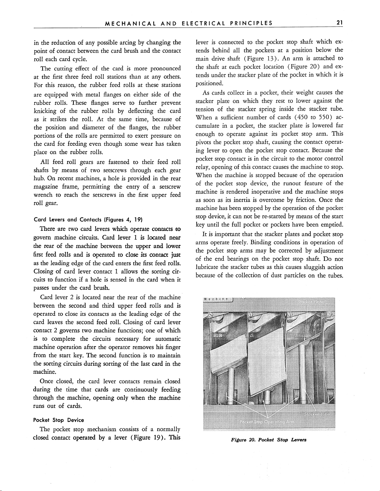
Figure
are friction driven from the rubber rolls above them.
This arrangement
tion because the
prohibits the
first and third lower
is
necessary at the second lower posi-
size
and location of the contact roll
use
of a regular
feed
size
lower
rolls are driven
feed
by
roll. The
18-tooth
worm gears meshed with the drive shaft. All other
lower feed rolls, with the exception of the auxiliary
feed
rolls, are driven
Downward pressure
by
roll
shaft bearing.
means of flat tension springs on each feed roll
One exception
by
19-tooth gears.
is
applied
to
to
each upper feed
this, however,
is
the
first upper feed roll which employs 2 small spring
loaded plungers
furnish the downward tension
neces-
to
sary for gripping the card firmly. These small plungers
are recessed upwards into the front and rear magazine
frames. Note that the flat tension springs for the second
upper feed roll are shorter than those for the other feed
rolls. All feed rolls, with the exception of the auxiliary
rolls, run in removable porous bronze bearings set in the
side frames of the machine.
As
stated above, some
feed
rolls are driven from 18-
19.
Feed
RoIls
tooth gears while others are driven from 19-tooth gears.
From this, it will be apparent that the shafts with 18tooth gears will turn faster than those with 19-tooth
is
gears. Therefore, it
necessary that those feed rolls
having 19-tooth gears be enough larger in diameter
than the two having 18-tooth gears to make the peri-
pheral speeds of all rolls the same.
The first and third lower feed rolls, which are driven
by
18-tooth gears, make one complete revolution per
cycle.
It
is
card
necessary that these two shafts make
one revolution per cycle because the commutator
mounted on the first shaft and the armature knock-off
is
screw
mounted on the third shaft. The commutator
and the armature knockoff must stay in synchronism
with the movement of the card at all times.
by
All other geared rolls are driven
and make
18/19
of one revolution per card cycle.
19-tooth gears
This distributes the cutting effect of the cards on the
feed rolls since the leading edge of the card does not
strike the same spot on the feed rolls each cycle. The
is
contact roll
also driven
by
a 19-tooth gear. This aids
is
Page 22
M E C
HAN I CAL
in the reduction of any possible arcing
by
AND
changing the
point of contact between the card brush and the contact
roll each card cycle.
is
The cutting effect of the card
more pronounced
at the first three feed roll stations than at any others.
For this reason, the rubber feed rolls at these stations
are equipped with metal flanges on either side of the
rubber rolls. These flanges serve to further prevent
by
knicking of the rubber rolls
as
it strikes the roll. At the same time, because of
deflecting the card
the position and diameter of the flanges, the rubber
portions of the rolls are permitted to exert pressure on
the card for feeding even though some wear has taken
place on the rubber rolls.
feed
All feed roll gears are fastened to their
by
shafts
hub.
means of two setscrews through each gear
On recent machines, a hole
is
provided in the rear
roll
magazine frame, permitting the entry of a setscrew
wrench to reach the setscrews in the first upper feed
roll gear.
Card
Levers
and Contacts (Figures 4, 19)
There are two card levers which operate
contact'S
to
govern machine circuits. Card lever 1 is located near
the
rear of the machine between the upper and lower
first
feed rolls and
as
the leading edge of the card enters the first feed rolIs.
Closing of card lever contact 1 allows the sorting
cuits
to
function if a hole
is
operated
to
close
:its
contact just
is
sensed in the card when it
cir-
passes under the card brush.
is
Card lever 2
between the second and third upper feed rolls and
operated to close its contacts
located near the rear of the machine·
is
as
the leading edge of the
card leaves the second feed roll. Closing of card lever
contact 2 governs two machine functions; one of which
is
to complete the circuits necessary for automatic
machine operation after the operator removes his finger
from the start
The second function
is
to maintain
key.
the sorting circuits during sorting of the last card in the
machine.
Once closed, the card lever contacts remain closed
during the time that cards are continuously feeding
through the machine, opening only when the machine
runs out of cards.
E L E C T R
lever
IC
ALP R INC
is
connected to the pocket stop shaft which
I P L E S
tends behind all the pockets at a position below the
13).
main drive shaft (Figure
An arm
the shaft at each pocket location (Figure
is
20)
tends under the stacker plate of the pocket in which it
positioned.
As cards collect in a pocket, their weight causes the
stacker plate on which they rest to lower against the
tension of the stacker spring inside the stacker tube.
When
cumulate in a pocket, the stacker plate
a sufficient number of cards (450 to
is
enough to operate against its pocket stop arm. This
pivots the pocket stop shaft, causing the contact
ing lever to open the pocket stop contact. Because the
is
pocket stop contact
in the circuit to the motor control
relay, opening of this contact causes the machine to stop.
is
When the machine
stopped because of the operation
of the pocket stop device, the runout feature of the
is
machine
as
soon
machine has been stopped
stop device,
rendered inoperative and the machine stops
as
its
inertia
it
can not be re-started
is
overcome
by
by
friction. Once the
the operation of the pocket
by
means of the start
key until the full pocket or pockets have been emptied.
It
is
important that the stacker plates and pocket stop
arms operate freely. Binding conditions in operation of
the pocket stop arms may be corrected
by
of the end bearings on the pocket stop shaft.
as
lubricate the stacker tubes
this causes sluggish action
because of the collection of dust particles on the tubes.
21
ex-
attached
and
to
ex-
is
550)
ac-
lowered far
operat-
adjustment
Do
not
Pocket Stop Device
The pocket stop mechanism consists of a normally
closed contact operated
by
a lever (Figure
19).
This
Fi~ure
:10.
Pocket
Stop
Levers
Page 23
CIRCUIT
DESCRIPTION
ALL
CIRCUITS described in the electrical principles of
Type 82 Card Sorting Machine will refer to wiring
the
diagram
plained will
AC, single phase machine
machine most prominently
for machines using a power supply other than
AC, single phase will
layout except
resistors, filter capacitors, or a transformer
chine power supply. These discrepancies in machine
wiring are noted
diagram.
Direct current
machine circuits with the exception of the motor
cuits and the tube heater circuits. Where the source
voltage
of extra resistors where the DC rating
Where the source voltage
rectifiers are employed to convert the
NOTE:
may
except for
the frame grounded at all
be
the switch
301701-D (Figure
be
the circuits incorporated in a 115 volt
be
for
the addition or subtraction of various
in
sections 3,
is
required
is
DC, there
The machine frame should
be
ungrounded at the customer's option; however,
230 volt DC machines, which must have
touched
by
is
on and the frame grounded.
is
operating personnel can
55).
Those circuits
since
this
is
the type of
in
use
in the
field.
Circuits
115
found to be very similar in
in the
4,
5 and 6 of the wiring
for
the operation of all
no problem except for the
is
230 volts.
is
AC however, selenium
AC
to
DC.
be
grounded.
times.
No point which can
be
hot when
ex-
volt
ma-
cir-
use
It
The connection of selenium rectifiers in an AC
cuit permits current
though the
converting alternating current to pulsating direct
rent. However, because of the limitation in reverse
voltage which each
discs
order to properly rectify a normal source voltage of
115
volts AC which has a peak inverse voltage of
proximately 150 volts. Full wave bridge rectifier circuits with filter capacitors and bleeder resistors are
used
machines.
The rectifier output voltage should be between
and
145
200, or 230 volts), with the machine stopped and the
sort magnet continuously energized.
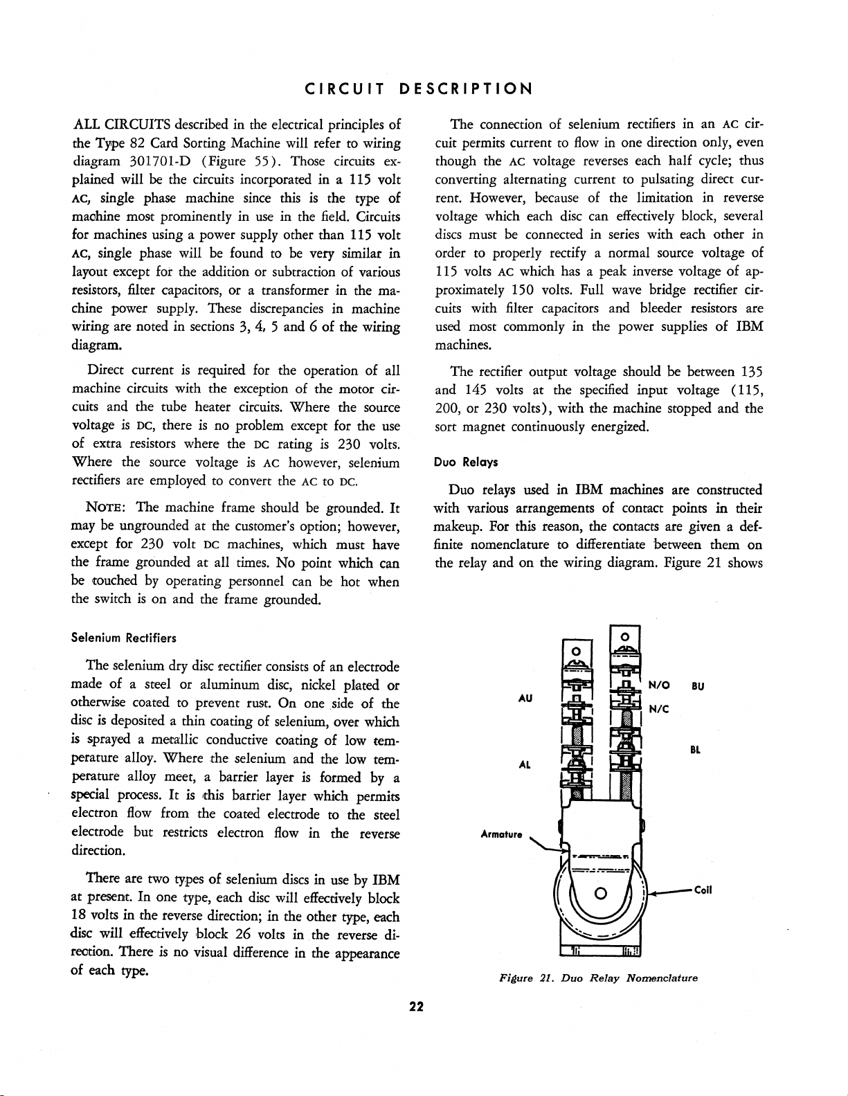
Duo Relays
Duo relays used
with various arrangements of contact points
makeup. For
finite nomenclature
the relay and on the wiring diagram. Figure
AC
must
be
most commonly in the power supplies of IBM
volts at the
this reason, the contacts
to
flow
in
one direction only, even
voltage reverses each half
disc
can effectively block, several
connected in
in
to
series
with each other in
specified
IBM machines are constructed
differentiate between them on
input voltage ( 115,
are
cycle;
given a def-
21
in
shows
cir-
thus
cur-
ap-
135
their
Selenium Rectifiers
The selenium dry
made of a steel or aluminum
otherwise coated to prevent rust. On one
disc
is
deposited
is
sprayed a metallic conductive coating of low tem-
perature alloy. Where the selenium and the low
perature alloy meet, a barrier layer
special
electron
electrode but restricts electron
direction.
at present. In one type, each
18 volts
disc will effectively block 26 volts in. the reverse
reotion. There
of each type.
process.
flow
There are two
in
the reverse direction; in the other type, each
disc
rectifier
a thin coating of selenium, over which
It
is
this barrier layer which permits
from the coated electrode to the steel
types
of selenium
is
no visual difference
disc
consists
disc,
of an electrode
nickel plated or
is
formed
flow
in the reverse
discs
in
will
effeccively
in
the appearance
side
use
of the
by
block
tem-
by
IBM
di-
AU
AL
a
Armature
Fj~ure
~
21.
Duo
~"/C
,-_-Coli
Relay
Nomenclature
BU
BL
22
Page 24
CIRCUIT
DESCRIPTION
23
an armature end
view
of a standard duo relay with the
different contact points properly identified.
Glossary
of
Terms
and
Abbreviations
Listed below are some of the terms and abbreviations
used
in connection with the Type 82 wiring diagram.
NjC
NjO
OjP
VI
VI-4
AC
DC
R2
TD
MC
MC-BL
TD-BU
Time Delay Relay
A time delay relay
render the
Normally Closed Point
Normally Open Point
Operating Point
Tube I .
Tube
1,
Alternating Current
Direct Current
Resistor 2
Time Delay
Motor Control
Motor Control Relay
Time Delay Relay
is
employed in the machine
staJlt
key
inoperative for 50 to 60
Pin 4
BU
BL
Point
Point
to
seconds
after turning on the main line switch. This delay
necessary to allow the electron tube filaments to reach
operating temperature before sorting begins.
strap, composed of two dissimilar metals,
A contact
is
heated by
passing current through a coil of wire wrapped around
the strap. Heating of this strap
definite direction and, after having
enough distance, a contact point riveted
causes
it to flex in a
flexed
a great
1:0 the strap
makes contact with another adjustable contact point
and completes a circuit to pick
The duration of time required
be
relay to pick may
air gap between the A points
the
altered
up the time delay relay.
to
cause the time delay
by
increasing or decreasing
by
means of the
ad-
justing screw on the outer contact strap.
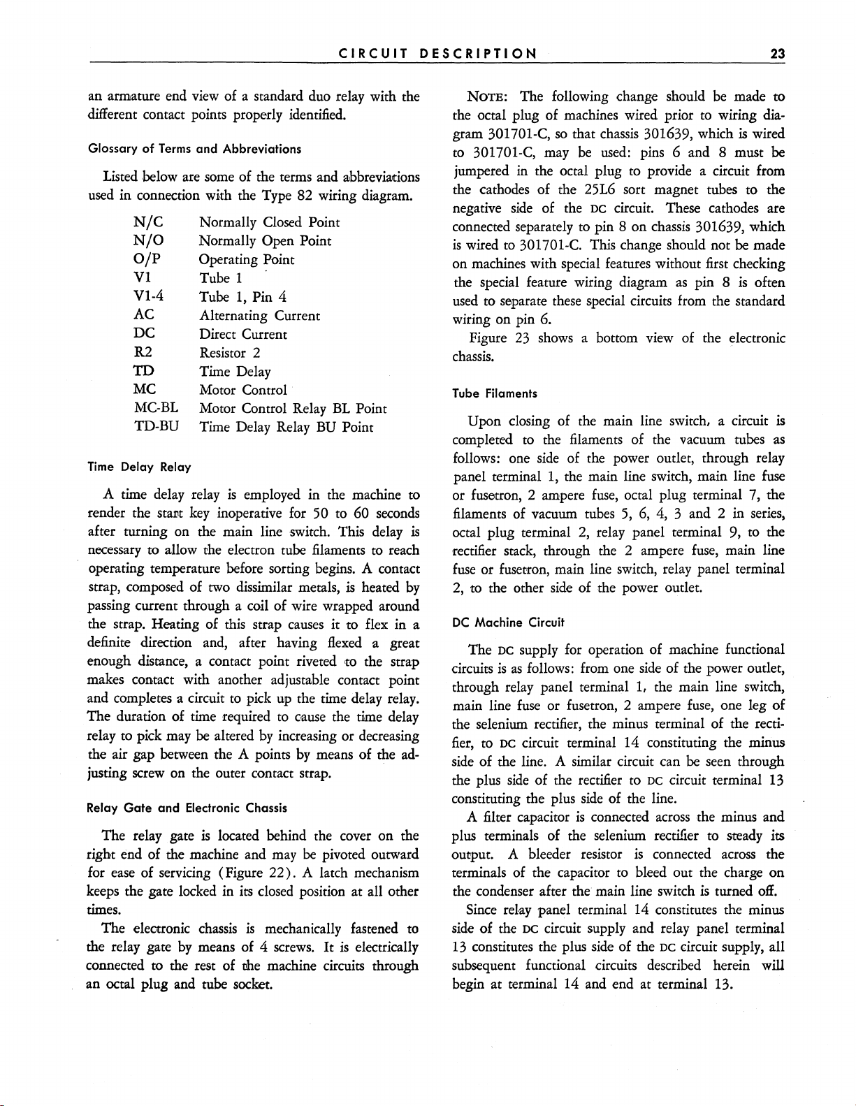
Relay
Gate
and
Electronic Chassis
The relay gate
right
end of the machine and may
for ease of servicing (Figure
keeps the gate locked in
is
located behind the cover on the
be
pivoted outward
22).
A latch mechanism
its
closed position at all other
times.
The electronic
the relay gate
connected
to
chassis
by
means of 4 screws.
the rest of me machine circuits through
is
mechanically fastened
It
is
to
electrically
an octal plug and tube socket.
NOTE:
The following change should be made
the octal plug of machines wired prior to wiring diagram 301701-C,
to
301701-C, may
so
that
be
chassis
used:
301639, which
pins 6 and 8 must be
jumpered in the octal plug to provide a circuit from
the cathodes
negative
connected
is
wired to 301701-C. This change should not be made
of
the 25L6 sort magnet tubes to the
side
of the
DC
circuit. These cathodes are
separately to pin 8 on chassis 301639, which
on machines with special features without first checking
the special feature wiring diagram
used
to separate these special circuits from the standard
as
pin 8
wiring on pin 6.
Figure
23
shows
a bottom view of the electronic
chassis.
Tube Filaments
Upon closing of the main line switch, a
completed to the filaments of the vacuum tubes
follows: one side of the power outlet, through relay
panel terminal
or fnsetton, 2 ampere
filaments of vacuum tubes
is
octal plug terminal
rectifier stack, through the 2 ampere
fuse
or fusetron, main line switch, relay panel terminal
I,
the main line switch, main line
fuse,
octal plug terminal 7, the
5,
6,
4, 3 and 2 in series.
2,
relay panel terminal 9, to the
fuse,
2, to the other side of the power outlet.
DC
Machine Circuit
The
DC
supply for operation of machine functional
circuits
through relay panel terminal
main line
is
as
follows: from one
fuse
or fusetron, 2 ampere
side
of the power outlet,
1,
the main line switch,
fuse,
the selenium rectifier, the minus terminal of the rectifier,
to
DC
circuit terminal 14 constituting the minus
side of the line. A similar circuit can
the plus
constituting the plus
side
of the rectifier to DC circuit terminal 13
A filter capacitor
side
of the line.
is
connected
be
across
the minus and
plus terminals of the selenium rectifier to steady its
output.
A bleeder resistor
is
connected
terminals of the capacitor to bleed out the charge on
the condenser after the main line switch
Since relay panel terminal 14 constitutes the minus
DC
side of the
13
constitutes the plus side of the
circuit supply and relay panel terminal
DC
circuit supply, all
subsequent functional circuits described herein
begin at terminal 14 and end at terminal 13.
is
wired
is
often
cirCUit
fuse
main line
one leg
seen through
is
turned
across
the
off.
will
to
15
as
of
Page 25
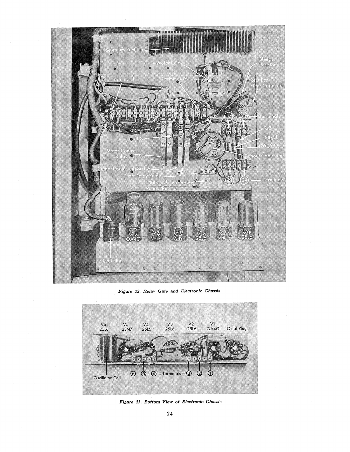
Figure 22.
Relay
Gate
and
Electronic Chassis
Figure 23.
Bottom
View
24
of
Electronic
Chassis
Page 26
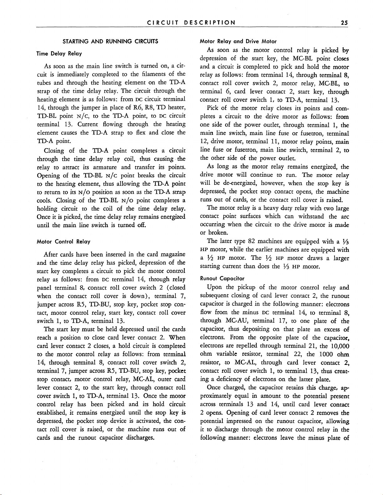
CIRCUIT
DESCRIPTION
25
Time
As
cuit
STARTING
Delay Relay
soon
as
is
immediately completed
AND RUNNING
the main line switch
to
CIRCUITS
is
turned on, a cir-
the filaments of the
tubes and through the heating element on the TD-A
strap of the time delay relay. The circuit through the
heating element
14, through the jumper
TD-BL point
is
as
follows: from
in place of R6, R8,
N/C,
to the TD-A point, to
DC
circuit terminal
TD
DC
heater,
circuit
terminal 13. Current flowing through the heating
element
causes
the TD-A strap to
flex
and close the
TD-A point.
Closing of the TD-A point completes a circuit
through the time delay relay coil, thus causing· the
relay to attract its armature and transfer
Opening of the TD-BL
to
the heating element, thus allowing the TD-A point
to
return
to
its
N/O
cools. Closing of the TD-BL
holding circuit
Once it
is
to
picked, the time delay relay remains energized
until the main line switch
Motor Control Relay
N/C
point breaks the circuit
position
as
soon
as
N/O
point completes a
the coil of the time delay relay.
is
turned
off.
its
points.
the TD-A strap
After cards have been inserted in the card magazine
and the time
start
key
relay
as
delay relay
has
picked, depression of the
completes a circuit to pick the motor control
follows: from
DC
terminal 14, through relay
panel terminal 8, contact roll cover switch 2 (closed
when the contact roll cover
jumper
across
R5, TD-BU, stop
tact, motor control relay, start
switch
1,
to
The start
TD-A, terminal 13.
key
must
be
reach a position to close card lever contact
card lever contact 2
to
the motor control relay
14, through terminal
terminal 7, jumper
closes,
8,
across
stop contact, motor control relay,
lever contact
cover switch
2,
to the start
1,
to
Tn-A,
control relay has been picked and
established, it remains energized until the stop
depressed, the pocket stop device
tact roll
. cover
is
raised, or the machine runs out of
is
down), terminal 7,
key,
pocket stop con-
key,
contact roll cover
held depressed until the cards
2.
When
a hold circuit
as
follows: from terminal
is
completed
contact roll cover switch
R5, TD-BU, stop
MC-AL,
key,
through contact roll
key,
pocket
outer card
terminal 13. Once the motor
its
hold circuit
key
is
activated, the con-
cards and the runout capacitor discharges.
2,
Motor Relay and Drive Motor
As
soon
as
the motor control relay
depression of the start
and a circuit
relay
as
is
completed
follows: from terminal
contact roll cover switch
terminal 6, card lever contact
contact roll cover switch
Pick
of the motor relay closes
pletes a circuit to the drive motor
one
side
of the power outlet, through terminal
main line switch, main line
key,
the
MC-BL
to
pick and hold the motor
14,
through terminal 8,
2,
motor relay,
2,
start
1,
to
TD-A, terminal 13.
its
points and com-
as
fuse
or fusetron, terminal
12, drive motor, terminal 11, motor relay points, main
line fuse or fusetron, main line switch, terminal
the other
As
drive motor will continue
long
side
of the power outlet.
as
the motor relay remains energized, the
to
run. The motor relay
will be de-energized, however, when the stop
depressed, the pocket stop contact opens, the machine
runs out of cards, or the contact roll cover
The motor relay
is
a heavy duty relay with two large
contact point surfaces which can withstand the arc
occurring when the circuit
to
the drive motor
or broken.
The later type 82 machines are equipped with a
HP
motor, while the earlier machines are equipped with
a
Y2
HP
motor. The
starting current than does the
Runout
Capacitor
Y2
HP
motor draws a larger
Y3
HP
motor.
Upon the pickup of the motor control relay and
subsequent closing of card lever comact
capacitor
flow
through
is
charged in the following manner: electrons
from the minus
MC-AU, terminal 17,
DC
terminal 14, to terminal 8,
to
one plate of the
capacitor, thus depositing on that plate an
electrons. From the
electrons
are
repelled through terminal 21, the 10,000
opposite
plate of the capacitor,
ohm variable resistor, terminal 22, the 1000 ohm
resistor, to MC-AL, through card lever contact 2,
contact roll cover switch
1,
to terminal 13, thus creat-
ing a deficiency of electrons on the latter plate.
Once charged, the capacitor retains this charge, approximately equal in amount to the potential present
across
is
2 opens. Opening of card lever contact 2 removes the
terminals
13
and 14, until card lever contact
potential impressed on the runout capacitor, allowing
it
to
discharge through the motor control relay in the
following manner: electrons leave the minus plate of
is
picked by
point closes
MC-BL,
key,
to
through
follows: from
1,
the
2,
to
key
is
is
raised.
is
made
13
2,
the runout
excess
of
Page 27

26
CARD
SORTING
MACHINE,
TYPE
82
the capacitor, travel through terminal 17, MC-AU,
terminal 8, contact roll cover switch
jumper in place of R5, TD-BU, stop
contact, motor control relay,
ohm
resistor, terminal 22, 10,000 ohm variable
MC-AL,
terminal 18, 1000
terminal
key,
pocket stop
7,
re-
2,
sistor, terminal 21, to the positive plate.
This discharge keeps the motor control relay
until the current
flow
from the capacitor falls below
piCked
the value required to hold the relay energized. As long
as
the motor control relay remains
piCked,
me MC-BL
point maintains a circuit through the motor relay, and
the motor relay points, in turn, maintain a circuit to
the drive motor. Prolongation of the circuit to the
drive motor in this manner allows the last card in the
machine to be fed to its proper pocket before the
machine stops.
10,000 ohm variable resistor in series with the
The
so
runout capacitor should be adjusted
.5
motor will keep running for
to 1 second after the
that the drive
last card drops in the 9 pocket. Decreasing the effective
value of the variable resistor will prolong the runoue
time; increasing the effective value of the variable
resistor will shorten the runout time.
is
The runout circuit
event. that the machine
rendered inoperative in the
is
stopped through opening of
the pocket stop contact, raising of the contact roll
key.
cover, or depression of the stop
Under
of these conditions, the machine will coast to a stop
soon
as
its inertia
47,000 ohm resistor
The
is
overcome
by
friction.
whiCh
shunts the terminals
anyone
as
of the runout capacitor serves to bleed off the charge
after the machine has been stopped through operation
of
the pocket stop device, raising of the contact roll
cover, or depression of the stop
SORTING
BECAUSE
the Type 82 sorter operates at a speed of
key.
CIRCUITS
650 cards per minute, the sort magnet armature must
be attracted very quickly
(.005 seconds or less)
the cards will sort properly without being nicked
the tips of the chute blades. Relay operation,
80 sorter,
Type
fore, an
electroniC circuit
is
not dependable at this speed; there-
is
used.
Not
only does the
as
so
that
in the
by
electroniC circuit provide the necessary speed of operation, but it also eliminates burning at the contact roll
and the selector commutator because of the small
amount of current used to control the energization of
the sort magnet.
tJhe
Before proceeding with
study of the sorting
be
circuits, it may
well to review some of the
principles of electronics
as
an aid to the better under-
basiC
standing of these circuits.
1.
In
this presentation, current
lished synonymous with electron
as
considered
2.
When
voltage
flowing from negative to positive.
current
is
negative on the end of the resistor where
flows
flow
shall be estab-
flow
and shall be
through a resistance, the
the current enters and positive on the end where the
current leaves.
3.
When
network there will
there
is
no current flowing in a
be
no voltage drops across any given
res~tor
resistors in that network.
4.
The term "ground" refers to a zero potential
is
value. Usually the negative power input lead
at
sidered to be
from this reference may
ground potential. Voltages measured
be
positive (above ground)
con-
or negative (below ground).
5.
Current or electron
a gas tube
is
always from the cathode to the anode
(plate) and can take place only when the anode
flow
in a vacuum tube or
is
positive in respect to the cathode.
6. The control grid
of
a vacuum tube
is
physiCally
located between me cathode and the anode and acts
as
a valve in regulating the
cathode to the anode. This control
flow
of electrons from the
is
accomplished
by
varying the amount of negative voltage applied to the
grid. Increasing the negative voltage on the grid can
flow
slow down or completely cut off electron
from
cathode to anode, even though the anode (and screen
grid) are positive in respect to the cathode. Decreasing
the negative voltage on the grid can start or speed up
as
long
as
electron flow from cathode to anode
anode
is
positive in respect to the cathode.
7.
The constant DC voltage applied between the
control grid and the cathode of a tube
bias
voltage.
control grid, it
potential and
is
applied .to the cathode, it
the voltage on the control grid and
bias.
Regardless of whether grid
is
used,
When
is
is
called grid bias.
the purpose
such a voltage
is
negative with respect to the cathode
When
is
positive with respect to
is
bias
or cathode bias
of
both
is
to make the control grid
is
called the
applied to the
such a voltage
called cathode
the
negative with respect to the cathode.
8.
The screen grid of a vacuum tube, physiCally
located between the control grid and the anode, may
have a positive voltage applied to it, thus aiding the
anode in attracting electrons away from the cathode.
Page 28

CIRCUIT
DESCRIPTION
27
In performing this function, not all the electrons pass
through this grid and on to the anode but some strike
pass
the screen grid wires and
cuit to cause the
other important
do
not apply in the Type 82 circuits.
9. Gas tubes, such
flow
of screen current. There are
uses
of the screen grid. However, they
as
on into the screen
the OA4G, have the unique
characteristic of not starting conduction until the
cir-
starting anode receives the required positive voltage. Once
ionization or conduction begins, however, the starting
loses
anode
can
or
by
be
all control, and current
cut
off
only
by
opening the main anode circuit
decreasing the positive voltage on the main
anode to a value insufficient
65
(approximately
General Operation
The
flow
of current
by
three 25L6 beam power tetrodes connected in paral-
lel. This
flow
to 70 volts for an OA4G tube).
to
the sort magnet
of current
is
under control of an OA4G
flow
in the tube
to
maintain ionization
is
furnished
cold cathode gas triode which serves the same purpose
as
does
the card brush relay in the Type 80 sorter.
OA4G, or trigger tube,
The
is
fired
by
the action of
the card brush sensing a punched hole and, being a gas
tube, it remains in conduction until the anode circuit
is
broken
the
end of the card cycle (principle
Oscillator and Rectifier Tube
Approximately
by
the center brush of the commutator at
9).
-40
to
-45
volts
bias
(principle
7)
for the 25L6 power tubes and the OA4G trigger tube
is
supplied
fies
a high audio frequency voltage (approximately
4.3KC) supplied
triode connected 25L6.
bias supply
rectifier setup
applicable on both
oscillator operate continuously when the machine
turned on and the contact roll cover
-40
to
by
is
not feasible for
-45
volts
a diode connected 12SN7, which recti-
by
a Hartley type oscillator using a
Since a transformer and rectifier
DC
machines, an oscillator-
is
used
so
that machine circuits will be
AC
and DC. The bias rectifier and
is
is
always available
down,
as
required.
so
that
is
The oscillator and rectifier are shown schematically
in Figure 24. The rectified machine supply voltage
shown
as
150 volts DC because the power supply capa-
is
citors tend to charge to peak line voltage under a light
As
load.
the 25L6 oscillates, there
is
a constant rising
and falling of the plate current through the tube. The
speed at which this rising and falling of plate current
is
occurs
dependent on the resonant frequency
as
deter-
mined
by
the tank circuit made up of the .05 mfd.
capacitor and sections A and B of the oscillator coil.
is
in
Because the B section of the coil
series with the
tube, variations in plate current cause variations in the
current flowing through the B section of the coil.
in
Rising and falling values of current
the B section
of the coil induce voltages in sections A and C of the
coil. These induced voltages are alternating voltages
rise
which change polarity with each
and fall of the
current through the B section. The voltage induced
is
in the A section of the coil
to
the tube
keep the tube oscillating. The voltage
induced in the C section of the
terminal 5 and the cathodes of the
voltage changes polarity each half cycle, the
applied to the grid of
coil
is
applied across
12SN7. Since this
12SN7
conducts only on those half cycles during which its
is
anode
5).
output from section C of the
imately
positive in respect to its cathode (principle
Because of this action, the 12SN7 rectifies the
coil
to provide approx-
-40
to
-45
volts DC with respect to the
negative or zero side of the power supply.
When
the oscillator first starts to operate, the 4 mfd.
capacitor tends to charge through the circuit shown
dotted in Figure 24 on each half cycle that the
conducts. Because of its comparatively large
12SN7
size,
several oscillator cycles are required before the capacitor
becomes fully charged. As the condenser becomes
charged to the value of the voltage drop across section
40 to
45
C of the coil (approximately
flow
in the 12SN7 diminishes greatly because of the
volts), current
lack of a difference in potential between its anode and
its cathode.
Once charged, the 4 mfd. capacitor remains
charged except for a slight leakage through the 1
megohm resistor on those half cycles during which the
12SN7
the capacitor due to leakage
through the
does
not conduct. Any loss of charge across
is
replaced
by
12SN7. Except for the small amount of
conduction
current required to replace the charge that leaks from
flow
the 4 mfd. capacitor, current
is
practically zero after the capacitor
is
and before a hole
sensed in the card. Once the 4
mfd. capacitor becomes charged with the polarity
shown in Figure 24, a constant negative bias of
to
-45
volts
is
supplied, even though the induced
through the 12SN7
is
initially charged
as
-40
voltage in section C of the coil reverses polarity each
half cycle. Without this capacitor, negative bias would
be lost each half cycle that the
12SN7 did not conduct.
The 1 megohm resistor connected between the plate
Page 29

28
---~I~~----------------~O~»~~--~
+ 150
VOLTS
OF
25L6
~~
TO ANODES
TUBES
AND
7
~,
AND
ANODE
'0'
oo"'oc'""
OF
SCREEN
OA4G
GRIDS
TUBE
CARD
1
SORTING
SORT
MAGNET
MACHINE,
r-
----
- - -
I
Rl.230V
I
... ' .. ..
L
____________
.
v,,,
r------------,
I R4.230V
I I
L
__
:.:.:
---,
DC
ONLY I
..
...
'V "
."
DC
ONLY I
::'_'~:'~
__
TYPE
I
J
-'
82
CONTACT
COVER SWITCH 1
ROLL
+ 150
RECTIFIED
APPROXIMATELY 150 VOLTS
NO
LOAD
(APPROX. 115 VOLTS
VOLTS
DC
FOR
AC
OPERATION)
RELAY
TERM.
SUPPLY
OPERATION
FOR
GATE
13
DC
o VOLTS TO
CATHODES OF
25L6
TUBES
---~~------~~~----------~--~~~----------------~~~----------~
I
- ,
APPROX. -
START
40
VOLTS
BIAS
TO
CONTROL GRIDS OF
TUBES
AND
ANODE
of
the 12SN7 and the plus
serves
to
The
470,000 ohm resistor and .001 mfd. capacitor
25L6
CATHODE
AND
OF
OA4G
TUBE
stabilize the bias circuit.
Figure 24.
side
of the DC supply
Schematic
in the oscillator circuit provide signal grid bias for
the rube.
The condition of the 25L6 oscillator tube should be
checked occasionally
4 mfd. condenser.
by
placing a voltmeter
If
this reading
is
below
across
25
the
volts
in a static condition, the 25L6 tube may be faulty. (See
the voltage chart and notes on wiring diagram
301701- D.)
Static Circuit Conditions (Figure 25)
Prior to the time that a hole
brush, both ends of the
-40
to
-45
volts,
10,000 ohm resistor will be
as
will the control grids of the
25L6 power tubes and the cathode of the
(principle
also be at
3).
The starter anode of the OA4G will
-40
to
-45
volts through the 47,000 ohm
is
sensed
by
the card
at
OA4G tube
01
Oscillator
and the
of the
is
the bias network. Neither will
through the 25L6 power rubes to the sort magnet
these tubes are biased beyond cutoff at this time (principles 6 and
approximately
capacitor tends
light loads.
power tubes, both the anodes and the screen grids of
these tubes will be at the maximum positive potential
of
of the
brushes on the commutator are electrically connected,
potential through R2 when the center and outer
but before a hole
OCTAL
PLUG
PINS
6&8
INDUCED AC ACROSS
THIS
SECTION OF COIL
and
Rectifier
470,000 ohm resistors connected to one end
10,000 ohm resistor and the bias supply. This
a static condition and no current will be flowing in
7).
150 volts DC because the power supply
to
Because
no
current
150 volts (card lever contacts closed). The anode
OA4G tube will also be at 150 volts positive
CONTACT
COVER SWITCH 2
ROLL
RELAY
GATE
TERM.
14
o---~O~VO~L~TS~---o
(GROUND
POTENTIAL)
any
current be flowing
as
The rectified supply voltage will be
charge
is
to
peak line voltage under
is
flowing through the 25L6
sensed in the card.
Page 30

CIRCUIT
DESCRIPTION
29
Firing the Trigger Tube
As
soon
as
the card brush makes contact with the
contact roll through a hole in the card,
is
applied to the starting anode of the OA4G and more
than cancels the
network. This causes the tube
resistor limits
tube
fires.
-40
volts applied from the
to
fire.
the starting anode current when the
Firing of the OA4G tube allows current
from the negative
roll cover switch
section of the oscillator coil,
side
of the line, through contact
2,
octal plug pin 6, the lower
12SN7, 10,000 ohm
+150
volts
bias
The 47,000 ohm
to
flow
resistor, cathode to main anode of the OA4G, octal plug
pin 4, center to outer commutator brushes, R2, card
lever contacts, contact roll cover switch 1, to the
tive side of the line. Current
causes
a voltage drop of approximately 60 volts
the 10,000 ohm resistor with the polarity
Figure
polarity of the
25
(principle
2),
40 volt negative bias on the grids of
the 25L6 power tubes and tends
to
a value of approximately 20 volts positive with
respect
However,
flows
voltage drop
the polarity
to
their cathodes which are at zero potential.
as
soon
as
the grids become positive, current
in the grid circuit of each tube and
across
the 47,000 ohm grid resistors with
is
shown in Figure 25. This lowers the
positive potential on the grids
flow
through this circuit
as
This polarity opposes the
to
swing these grids
to
a value only slightly
posi-
across
shown in
causes
greater than the cathodes.
The 4 mfd. capacitor partially discharges through
the
OA4G tube each half
voltage
opposes the main
across
the lower section of the oscillator coil
DC
charge when the alternating voltage
section of the oscillator coil
In
this respect, the capacitor acts
and tends
OA4G tube
to
keep the bias supply steady when the
is
conducting. Although the 4 mfd. capa-
citor steadies the bias supply when the
cycle
that the alternating
voltage. The capacitor tends to
across
aids
the main DC voltage.
as
a half wave filter
the lower
OA4G
is
conducting, the bias supply decreases in value at this time
from
-40
OA4G
ceases
volts to
to
-30
volts or
less.
When
conduct at the time the center
the
com-
mutator brush opens the circuit, the 4 mfd. capacitor
fully charges
is
again placed on the power tubes and the cathode
and starting anode of the
Energizing the Sort
With
as
before, and
-40
to
-45
volts bias
OA4Gtube.
Magnet
the negative bias removed from the grids of
the 25L6 power tubes, they immediately conduct (prin-
ciple
6)
from the negative side of the line, through
contact roll cover switch 2, octal plug pin 8, 25L6
cathodes, 25L6 anodes, octal plug
1,
card lever contacts, contact roll cover switch
positive
magnet. The initial surge
tubes
side
of the line; thus energizing the sort
of
current through the 25L6
is
of a comparatively large value due
action of the 8 mfd. capacitor in the screen grid circuit
of the 25L6 power tubes. This capacitor charges up to
the line potential of
switch
is
turned on.
from the control
to
go into conduction, the charge on the 8 mfd.
150 volts
When
grids
of the 25L6 tubes, causing them
as
soon
as
the grid bias
capacitor maintains a high positive potential on the
screen grids; thus producing a peak plate current flow
through the tubes (principle
8).
This initial heavy
current surge through the three 25L6 tubes lasts only
a short time.
As
the capacitor discharges through the
screen grid circuits, the positive potential on the screen
grids,
decreases, finally reaching a steady state value of
approximately
across
the 4,700 ohm resistor. Lowering the screen
65
volts because of the voltage drop
grid voltage in this manner causes the plate current
to
a
decrease
to
its
normal steady state value. The fore-
going action described gives a large initial impulse to
the sort magnet, causing fast attraction of the sort
magnet armature; after which the current through the
sort magnet tapers
tude, however, to keep the
Steady state current
on a 115 volt
off,
remaining in sufficient magni-
armature attracted.
flow
through the sort magnet
AC
machine should be approximately
220 MA, measured when a punched card
the machine
current
approximately 165
current scale
by
hand.
flow
measured in this manner should be
is
not available, the voltage drop across
MA.
On
a 115 volt
If
a meter with the proper
the sort magnet can be measured, and should be approximately
for 115 volt
13
volts for
DC
machines. Steady state current
AC
machines and 10 volts
through the sort magnet should never fall below 140
MA
on either AC or DC operated machines. This value
of
140
MA
through the sort magnet
a drop of 8.4 volts
across
the sort magnet falls below
voltage
is
correct, it may be an indication that one or
it.
140
is
comparable to
If
the current through
MA
when the line
more of the 25L6 power tubes are weak.
The action of the 8 mfd. capacitor and the
sort magnet,
1,
to the
to
the
the main line
is
removed
is
fed
through
DC
machine,
flow
4,700
Page 31

RESISTOR
COLOR
BLACK
BROWN 1
RED
ORANGE 3
YELLOW
GREEN
BLUE
VIOLET
GRAY
WHITE
NONE
SILVER
GOLD
CODE
VALUE
SORT
MAGNET
0
+ 150
VOLTS
2
4
5
6
7
8
9
+ 150
VOLTS
OCTAL
PLUG
4
PIN
cf
8
11"1
~
z
o
u
o
~
M
...
..,j.
CONTACT
COVER
CARD
CONTACTS
ROLL
SWITCH
LEVER
1
'"
RELAY
GATE
TERM.
0-----0+
+ 150
13
VOLTS
o
Co)
t
APPROX.
RECTIFIED
APPROX.
NO
LOAD
(APPROX.
.05
MFD
CHASSIS
4MFD
10000.n.
+~.t----
-
40
VOLTS
Figure
25.
Schematic
of
Type
82
Sorting
TERM.
Circuits
NO.5
6&8
NOTE:
115V AC
STATIC
IN
CARD.
DIRECTIONAL
SHOW
SENSED
VOLT
CONDITION -
ELECTRON
IN
CONTACT
COVER
AGE
VALUES
OPERATION
ARROWS
FLOW
THE
CARD.
DC
150
FOR
AC
715
VOLTS
OPERATION)
o
ROLL
SWITCH
SHOWN
AND
REPRESENT
NO
HOLE
ON
WHEN A HOLE
SUPPLY
VOLTS
OPERATION
FOR
VOLTS
RELAY
TERM.
2
ARE
FOR
A
SENSED
RESISTORS
IS
DC
GATE
14
Page 32

CIRCUIT
DESCRIPTION
31
ohm resistor also serves
25L6 power tubes
as
a protective device for the
by
reducing the initial high surge
of current through these tubes to a value below their
safe maximum continuous rating. Thus, if the machine
cycle
were stopped at a time in the card
when the
power tubes were conducting, the continuous flow of
be
current through the tubes would not
great enough
to cause damage.
Restoring Bias
When
the hole in the card passes from under the
card brush, thus insulating the brush from the contact
is
roll, the positive voltage
starter anode. This
does
stop conducting, however, since the starter anode
control of conduction in a gas tube after the tube
(principle
9).
The OA4G continues
removed from the OA4G
not cause the OA4G tube
loses
to
conduct until
to
fires
the center brush on the commutator opens the anode
circuit.
When
and current
resistor. The voltage drop across this resistor
lost (principle
this occurs, the OA4G
ceases
to
flow
through the 10,000 ohm
3),
and the control grids of the
is
extinguished
is
then
25
L6
tubes and the cathode and starting anode of the OA4G
are returned to
40 to 45 volts negative bias
oscillator and rectifier circuit. Restoring bias
by
to
the
the
grids of the 25L6 tubes causes these tubes to cease
conducting, thus de-energizing the sort magnet.
Between the 12 position of the leading card and the
9 position of the following card, the armature return
spring and the armature knockoff come into play to
to
restore the armature
its normal raised position in
preparation for sorting the following card.
Miscellaneous
Components
The 47 ohm resistors in the screen grid circuits of
the 25L6 power tubes suppress parasitic oscillation
as
which may appear
a result of operating tubes in
parallel.
circuit and cause
firing of the tube even though no
hole has been sensed in the card.
.05
The
mfd. and the 150 ohm resistor in series
between the cathode and the anode of the OA4G also
serve to by-pass transient impulses and prevent them
from firing the tube prematurely.
470K ohm resistor in the OA4G circuit connects
The
the starting anode to its cathode through the
10,000
ohm resistor, thus keeping the starter anode at its
own cathode potential whenever the card insulates the
card brush from the contact roll.
E Suffix
operation to machines which are wired to
D.
tube
power tube
Changes
Machines wired
to
301701-E are similar in circuit
30l701-C or
On the E
is
suffix
wiring diagram, the 12SN7 rectifier
replaced with a selenium rectifier. An additional
is
added in the circuit
to
the sort magnet.
This added power tube furnishes more current to the
sort magnet, thus increasing the safety factor of op-
was
eration. This
considered especially desirable for
DC-operated machines.
suffix
The E
electronic chassis consists of a flat plate
instead of the L-shaped chassis shown in Figures 22
is
and 23. The flat chassis
with the L-shaped chassis if the machine
electrically interchangeable
is
wired to
301701-D or 301701-C, or if the machine has been
altered in accordance with CEM 1213.
F Suffix
operation to those wired to
electronic chassis
as
Changes
Machines wired
that
used
for 301701-E. A running light
to
301701-F are similar in circuit
301701-C, D, or
is
physically and electrically the same
E.
is
The
in-
corporated in the circuit to indicate to the operator that
is
the machine
ready for operation. This light comes
on after the time delay relay picks up.
The
47,000 ohm resistors in the 25L6 control grid
circuits serve to limit the positive grid swing on conducrion which would otherwise allow excessive grid
current to damage the tube. These resistors also act
as
isolating resistors to prevent the development of parasitic oscillations in these tubes.
.001 mfd. capacitor between the cathode and the
The
to
starting anode of the OA4G serves
by-pass transient
impulses which may be introduced into the card brush
to
Machines wired
301701-F are Vinyl-covered ma-
chines and have several redesigned external features
which modernize the machine.
G Suffix
Change
Machines wired to 301701-G that operate on 115,
208, 230 volts AC, 50 or 60 cycle, obtain tube bias
voltage from a transformer which replaces the 25L6
bias
oscillator
circuit.
Page 33

PURPOSE
Motor
Control Relay
The primary function of this relay
starting of the machine
depression of the start
when the start key
as
long
as
the machine
by
key.
is
depressed and remains energized
is
running.
OF
RELAYS,
is
to prevent
any means other than
This relay
When
is
picked up
the machine
by
runs out of cards, the runout capacitor discharges
through this relay, holding it energized long enough
for the
MC-BL
point to keep the motor relay energized
and the drive motor running until the last card in the
machine
is
fed
to its proper pocket.
The MC-AL point, in conjunction with card lever
contact 2, completes a hold circuit to the motor control
In
its
N/O
relay.
the energization of the above relay except
of the start key in the event the machine
condition, this relay point prevents
by
means
was
stopped
with cards in the feed.
MC-AU point prevents a back circuit which
The
if
would make the contact roll hot
stopped with cards in the
cover
was
raised.
feed
and the contact roll
The MC-BL point completes a circuit
the machine
to
was
pick the
motor relay and hold it energized during automatic
machine operation.
Motor
Relay
This relay
complete a circuit to the drive motor.
is
a heavy duty relay. Its purpose
It
is
is
to
picked and
held energized under control of the motor control relay.
As
long
as
the motor relay remains energized, its points
complete a circuit to the drive motor.
Time Delay Relay
CONTACTS
AND
SWITCHES
After the time delay relay has picked, opening of this
point breaks the circuit to the heater coil.
The TD-BL
the time
The
TD-BU point
N/O
point provides a hold circuit for
delay
relay once it has been picked.
r~nders
the start key inoperative
until the time delay relay picks.
Card Lever Contact 1
This contact closes
as
the leading edge of the card
enters the first feed rolls. Closing of this contact allows
sorting of the first card.
Once closed, it remains closed
during the time that cards are continuously feeding
through the machine and, in conjunction with card
lever contact
furnishes circuits
to
the commutator
2,
and the sort magnet for sorting.
Card Lever Contact 2
This contact closes
leaves the second feed roll.
as
the leading edge of the card
Once closed, it remains
closed during the time that cards are continuously
feeding through the machine, and furnishes circuits to
the commutator and sort magnet for sorting and to the
motor control relay for automatic operation. This
tact maintains the necessary circuits for sorting the
last card.
Pocket Stop Contact
This contact
is
normally closed. Opening of this
contact when one or more card pockets become full
renders the runout circuit inoperative and causes
mediate dropout of the motor control relay. Dropout
of this relay opens the MC-BL point, de-energizing the
motor relay and stopping the machine
is
inertia
overcome
by
friction.
as
soon
as
con-
im-
its
The purpose of the time delay relay
is
to
prevent
starting of the machine until the tubes have reached
their proper operating temperature. Upon closing of
TD
the main line switch, current flowing in the
coils causes the TD-A contact strap to
flex,
heater
close its
contact point, and pick the time delay relay. The time
is
required to close the TD-A point
The
TD-BL
TD
heater when the main line switch
N/C
point allows a circuit through the
50 to 60 seeconds.
is
turned on.
Contact Roll Cover Switches 1 and 2
These two switches are held in a closed position
is
when the contact roll cover
lowered. Raising of the
contact roll cover opens both switches, breaking all
machine circuits and removing the potential from the
contact roll. These switches are installed
as
measure for operating personnel, and their operation
must not be crippled in any
way.
32
a safety
Page 34

IBM
80
CARD
SORTING
MACHIN~
FUNCTIONAL
THE TYPE 80 Card Sorting Machine (Figure 26)
forerunner of the Type 82 machine and performs the
same functions
Type
80, Model 1,
of the Type
Because of this reduced speed, the operation of high
speed relays
of the sort magnet, and an electronic circuit
necessary. The capacity of the card magazine
same
as
as
does the Type 82. The speed of the
is
450 cards per minute; the speed
80, Model
is
fast enough to control the energization
that on the Type 82 machine; 550 cards.
2,
is
250 cards per minute.
is
is
is
not
the
PRINCIPLES
a
THE
OPERATING
the same
line switch and the start and stop
The main line switch and the start and stop
located
line switch immediately furnishes power
and makes the start
protected
starting of the machine due to accidental depression
as
as
OPERATING
features on the Type 80 machine are
those on the Type 82, except for the main
shown in Figure 26. Turning on the main
by
a metal hood which prevents inadvertent
FEATURES
keys.
to
key
effective. The start key
keys
are
the machine
is
Figure 26.
Type
80 Card Sorting Machine
33
Page 35

34
CARD
SORTING
MACHINE,
TYPE
80
of this
key.
The stop key, when depressed, renders the
runout feature of the machine inoperative and causes
immediate stopping of the machine.
Current, Weight,
and
Dimensions
The maximum operating current, starting current,
and
fuse
rating of the Type
a
Y3
HP
motor should be:
Voltage
Volts Cycles
115
230
115 25
115
115
127
150 60 1
208 50
208 50
208 50 3
208 60 1
230
230 50 1
230 60 1
230 50 3
Group
DC
DC
50 1
60 1
50 1
25 1
Weight unpacked
Weight packed
Length
Width
Height
Phases
1
1
2
SO
Operating
Current
Amperes
4.1
2.3
5.2
5.5
5.3
5.0
4.3
3.8
2.8
2.4
3.6
2.9
3.0
2.9
2.1
machine equipped with
Starting
Current
Amperes
31.5
16.0 6
26.3 12
28.0 12
29.2
20.5
17.5
12.5
6.5 6
8.2
12.5
13.4
14.2
14.8 6
9.5 6
Main
Fuses
Amperes
12
12
12
12
6
6
6
6
6
445 pounds
735 pounds
63 inches
16 inches
45
inches
MECHANICAL
THE
MECHANICAL
are identical
to
AND
ELECTRICAL
PRINCIPLES
principles of the Type 80 Sorter
those of the Type
S2.
The electrical principles of the Type 80 machine
differ somewhat from those employed in the Type 82.
No tubes are present in the Type
fore, the
tubes to heat up
base
relay
use
of a time delay relay
is
not
necessary.
is
employed in place of tubes to
SO
machine; there-
to
allow time for
A high speed slate
aid
In
controlling the energization of the sort magnet.
When a hole
is
sensed in the card, a circuit
is
com-
pleted to energize the sort magnet and cause pickup
of a high speed slate base relay. This circuit
is
controlled through the card brush and the inner and outer
brushes on the commutator.
relay closes
its
contact point and maintains a hold
Pickup of the high speed
circuit to the sort magnet through the center and outer
commutator brushes. This hold circuit continues until
slightly after the
12
position on the card
has
passed
under the reading brush, thus completing the sensing
of any holes in that column.
As
on the Type 82
machine, if two holes are present in a column sensed,
and
rio
provisions are made
bars on the commutator
value, the card will sort according
sensed
by
the brush.
by
means of the contact
to
suspend sorting of one
to
the first value
Page 36

CIRCUIT
ALL
CIRCUITS described in the electrical principles of
the Type
diagram 16I847-N. A reproduction of this wiring
gram
will
single phase machine because this
prominently
using a power supply other than
phase will
80 Card Sorting machine will refer to wiring
is
shown in Figure 27. Those circuits explained
be
the circuits incorporated in a
in
use
in
the
field.
Circuits for machines
be
found
to
be
very similar in layout except
115
is
the type most
115
volt AC, single
volt AC,
dia-
for the addition or subtraction of various resistors, filter
capacitors, or a transformer
in the machine power
supply.
Direct current
machine circuits with the exception of the motor
cuits. Where the source voltage
is
required for the operation of all
is
DC, there
is
no prob-
cir-
lem except for the increase of resistor values where the
DC rating
voltage
ed
to convert the AC to DC.
NOTE:
may
except
frame grounded at all times.
touched
switch
Relay
is
greater than
is
AC, however, selenium rectifiers are employ-
115
volts. Where the source
The machine frame should be grounded.
be
ungrounded however, at the customer's option,
for
230 volt DC machines which must have the
No
point which can be
by
operating personnel can
is
on and the frame grounded.
Cabinet
be
hot when the
The relay cabinet, located on the right end of the
machine,
sistors, and capacitors. Figure 28
serves
as
a container for all
fuses,
shows
the relay cabinet
relays,
re-
with the cover removed.
DC
Machine Circuit (Figure 27)
The
DC
supply for operation of machine functional
circuits
let, through F3, the main line switch,
side
A similar circuit can be seen through the plus
the rectifier to the plus
is
as
follows: from one
side
of the power out-
F2,
the minus
of the rectifier, to the minus DC circuit terminal.
side
DC
circuit terminal.
A
filter capacitor
is
connected
across
the plus and
of
minus terminals of the rectifier to reduce ripple and
steady its output. A bleeder resistor
the terminals of the capacitor to bleed
after the main line switch has been turned
is
connected
off
across
its charge
off.
DESCRIPTION
Since
the circuit to the plus and minus DC circuit
terminals
has
been given, all subsequent circuits
described herein will begin at the plus
and will terminate at the minus
STARTING
Motor Relay
After
cards
and
AND
RUNNING
Card
Control Relay
have been inserted in the card magazine
DC terminal.
CIRCUITS
and the contact roll cover has been lowered, depression of the start
key
completes a circuit to pick the
card control relay and the motor relay
from the plus DC circuit terminal, through contact roll
cover switch
stop switch,
stOP
R-2, 2 ampere
minus
DC circuit terminal.
The start
key
the start
key,
fuse,
must be held depressed until the cards
key,
card control relay, pocket
motor relay, jumper in place of
contact roll cover switch 2, to the
1,
reach a position to close card lever contact
It
card lever contact 2 closes, a hold circuit
to the card control relay and the motor relay through
the card lever 2 contact points and the CCR-A point.
Once the card control relay and the motor relay are
picked up and their hold circuits established, they
main energized until the stop
pocket stop
raised,
or
device
is
actuated, the contact roll cover
the
machine runs out of cards and the run-
key
is
out capacitor discharges.
Drive Motor
As
soon
as
the motor relay
pleted to the drive motor
is
picked, a circuit
as
follows: from one
the power outlet, through F3, the main line switch,
drive motor, motor relay contact points, main line
switch, F4,
long
as
the motor relay remains energized, the drive
the other
side
of the power outlet.
to
motor will continue to run.
The motor relay
is
a heavy duty relay with· two
large contact point surfaces which can withstand the
arc occurring when the circuit to the drive motor
made or broken.
The later Type
1/3
HP
motor, while the earlier machines are equipped
with a
1/4
HP
80 machines are equipped with a
motor.
DC
terminal
as
follews:
2.
When
is
completed
re-
depressed, the
is
is
com-
side
of
As
is
35
Page 37

CARD
CARD
LEVER
LEVER
2
1
--,,---0-!>-~..-
47000.n.
RUNOUT
CAPACITOR
FOR
SLOW
MACHINES
DC
ONLY
SPEED
ONLY
FOR
AC
MACHINES
ONLY
FOR
DC
MACHINES
ONLY
CONTACT
COVER
ROLL
SWITCH
DC
CIRCUIT
TERMINALS
MOTOR
RELAY
F4
OFF
~~O""N--o-""""
3
1.
~
I
~
GREEN
~c..:0N
BLACK
F3
.,.0
\.j)---O"ON(~-----I-<~IU-'
OFF
l
MOTOR
RElAY
BOX
OFF~~~
OFF
___
~~--~~--------------------------------~~~~
GRE.EN
MOTOR
RELAY
BOX
MACHINE
CONTACTS
........
-o+C>-lh
:t
MACHINE
FRAME
~_2~M~
~_
~MF,DL-o-
...----0:<----:--0::,--;-----0
L_
...
____
FOR
LESS
_____
~ra
.----------0
J
FREQUENCIES
THAN
50
CYCLES
DC
DC
--------------------------------------------------------0 -
FRAME
TIME
CHART
CARD
BRUSH
9 8 7 6 5 4 3 2 1 0
11
12
+
+"
BLACK
WHITE
BLACK
WHITE
MAIN
LINE
FUSES
VOLTAGE
230
RES
R-l
R-2
R-3
R-4
AC
OR
DC
115
12A
6A
DC
IS
IN
230V
2-1500.n..
82oo0.n.
CONDENSER
115V
2-650.n..
JUMPER
160.1\. 300.n. 160.n.
47000.n.
R3
DC
3Q00.n.
UNIT
ALL
AC
2-650.n..
JUMPER
47000-"-
COMMUTATOR
ARMATURE
KNIVES
FORWARD
Figure 27.
CARD
CARD
KNOCKOFF
CENTER
OUTER
LEVER
"I
LEVER
2
TRAVEL
CARD
PILED
# 1
~-----------3~---------~--~~
Type
80
Wiring
Diagram
CARD
WIDTH
FEED
36
UP
ROLLS
BY
BETWEEN
CARDS
Page 38

CIRCUIT
DESCRIPTION
tact, raising the contact roll cover, or depressing the
key.
stop
The 47,000 ohm resistor which shunts the terminals
of the runout capacitor
after the machine
pocket stop
device,
depression of the stop
serves
has
been stopped
to bleed
off
by
operation of the
raising the contact roll cover, or
key.
37
the charge
Fi~ure
28.
Type
80
Relay
Cabinet
Runout
Capacitor
Upon starting of the machine and the subsequent
closing of card lever contact
charged to the DC circuit potential
cuit through contact roll cover switch
tact
2,
the 1,000 ohm resistor and capacitor in
and the
CCR-B
point.
2,
the runout capacitor
by
means of a
1,
card lever
is
cir-
con-
series,
Once charged, the capacitor retains its charge until
card lever contact 2 opens.
Opening of card lever
contact 2 removes the potential impressed on the runout
capacitor, allowing it
to
discharge through the
CCR-A
point, . the card control relay, the motor relay, contact
2,
roll cover switch
charge current
and the
keeps
the card control relay and the
motor relay picked until the current
CCR-B
point. This
flow
from the
dis-
capacitor falls below the value required to hold the
relay energized.
As
long
as
the motor relay remains
picked, the motor relay points maintain a circuit to the
drive motor. This allows the last card jn the machine to
be
fed
to
its proper pocket before the machine stops.
is
The runout circuit
is
machine
stopped
rendered inoperative when the
by
opening of the pocket stop
con-
SORTING
As SOON
as
the
card brush makes contact with the
tact roll through a hole in the card, a circuit
CIRCUITS
is
con-
com-
pleted to energize the sort magnet and the brush relay
as
follows: from the plus DC circuit terminal, through
1,
contact roll cover switch
2 in parallel, outer
to
mon brush, contact roll, card brush, brush
sort magnet,
minus
causes
DC
the attraction of
F7,
contact roll cover switch
circuit terminal. Energizing the sort magnet
card lever contacts 1 and
inner commutator brushes,
rel.ay,
2,
its
armature and the setup of
com-
R-l,
to the
the proper combination of raised and lowered chute
to
blades
Once it
direct the card
is
energized, the sort magnet
to
the desired pocket.
is
held energized
through the outer and center commutator brushes and
the brush relay contact point. This circuit holds the sort
magnet energized until the center brush breaks
tact on the commutator common shortly after the
position on the card
12
position ot the leading card and the 9 position of
passes
the card brush. Between the
con-
12
the following card, the armature return spring and the
armature knockoff
ture to its normal raised position in preparation
come
into play
to
restore the arma-
for
sorting the following card.
PURPOSE
Motor
Relay
The motor relay
to
complete a circuit to the drive motor.
when the start
OF
is a heavy
key
is
RELAYS
AND
duty relay. Its purpose
depressed and
CONTACTS
It
is
held energized
is
picked
primarily under control of the card lever contacts. When
the machine runs out of cards, the runout capacitor
discharges through this relay, holding it energized while
the last card
motor relay
is
fed
to its proper pocket.
is
energized, its points complete a circuit to
As
long
as
the
the drive motor.
Card
Control Relay
On machines built
since
February, 1951, this relay
a duo relay. On machines built prior to the above date,
is
is
Page 39

38
this relay
function
is
a high speed slate base relay. Its primary
is
to prevent starting of the machine
means other than the start
is
when the start key
long
as
the machine
THE
CCR-A
depressed and remains energized
is
running.
point,
in conjunction with card lever
CARD
key.
contact 2, completes a hold circuit
In
its
relay and the motor relay.
NjO
This relay
SORTING
is
to
the card control
condition, it pre-
by
picked
vents the energization of either of the above relays
cept
by
means of the start
is
stopped with cards in the
THE
CCR-B point prevents a back circuit which
key
in the event the machine
feed.
would make the contact roll hot if the machine
stopped with cards in the
cover
was
raised.
feed
and the contact roll
any
as
ex-
was
MACHINE,
Card
This contact
Lever
TYPE
Contact
closes
80
2
as
the leading edge of the card
leaves the second feed roll. Once closed, it remains
closed during the time that cards are feeding continuously through the machine, and furnishes circuits
to the commutator for sorting and to the card control
relay and the motor relay for automatic operation.
This contact maintains the circuit to the commutator
and contact roll for sorting the last card.
Pocket Stop
This contact
Contact
is
normally closed. Opening of this
contact, when one or more card pockets become full,
renders the runout circuit inoperative and causes immediate dropout of the card control relay and the motor
stOps
relay. Dropout of these relays
soon
as
its inertia
is
overcome
by
the machine
friction.
as
Brush Relay
This relay
is
pose
from the time an impulse
the card until the end of the card cycle when the
cuit
is
is
a high speed slate base relay. Its pur-
to provide a holding circuit for the sort magnet
is
sensed through a hole in
cir-
broken
by
means of the commutator center ring
and brush.
Card
Lever
Contact
This contact closes
1
as
the leading edge of the card
enters the first feed rolls. Closing of this contact allows
sorting of the first card. Once closed, it remains closed
during the time that cards are feeding continuously
in
through the machine and,
2,
lever contact
furnishes circuits
conjunction with card
to
the commutator
for sorting.
Contact
Roll
Cover Switches 1
and
2
These two switches are held in a closed position
is
when the contact roll cover
lowered. Raising of the
contact roll cover opens both switches, breaking all
machine circuits and
remO\liing
contact roll. These switches are installed
the potential from the
as
a safety
measure for operating personnel, and their operation
must not be crippled in any
5.0
Mfd
Condenser
way.
The action of the 5 mfd capacitor in series with the
sort magnet gives a large initial impulse
to
the sort
magnet when the card brush makes contact through
a hole in the card. This. causes fast attraction of the
off
armature, after which the current tapers
to hold
the sort magnet energized until the center brush on
the commutator breaks.
Page 40

IBM
75
CARD
SORTING
MACHINE
FUNCTIONAL
THE TYPE
75
Card Counting Sorter (Figure 29)
is
designed to count and/or sort cards according to the
perforations in a single column.
It
is
not possible to
count on one column and sort on another column at
the same time.
It
is
possible,
by
means of switch
con-
trols, to count without sorting, sort without counting,
or count and sort at the same time. Cards that are
multi-punched in a single column will sort on the
figure
of the highest order only (all commutator
tion switches out) but all punchings will
however, there should
be
more than
two
be
punched holes
selec-
counted.
If,
in a single column of a card, possibly only two holes
will
be
counted when sorting and counting
are
taking
PRINCIPLES
place together.
sorting, a maximum of four holes
may
be
There are fifteen
capacity. In addition to the twelve counters which
When
counting
is
taking place without
in a single column
counted without the possibility of error.
Veeder counters of
five
wheel
accommodate the pockets, 12 through 9 inclusive, there
is
a reject counter and two total counters. The reject
twO
the.-
total
counter counts all cards which are unpunched in
column being sensed
by
the card brush. The
counters consist of a subtotal counter and a grand
total counter. These total counters count all cards,
regardless of whether or not they are punched. The subtotal counter
is
reset during the operation in which all
Fj~ure
29.
Type
75
Card
39
Countjn~
Sorter
Page 41

40
CARD
SORTING
MACHINE,
TYPE
75
other counters are reset. The reset of the grand total
counter
is
selected
by
~he
operator under control of an
additional operating lever.
A standard Type
tion of the Type
80 Sorter
75
machine and all of the Type 80
is
used
in the construc-
sorting features have been retained. The mechanical
principles, removal procedures, and adjustments of the
Type
75
sorting mechanism on the
same
as
those on the Type 80 machine.
Speed and Capacity
The speed of the Type
minute for Model 1 and
Model
2.
75
250
The capacity of the card magazine
capacity of each of the
WITH
THE
exception of those items pertaining to the
fifteen
OPERATING
FEATURES
machine are the
Sorter
is
cards
per minute
is
counters
400 cards per
for
550 cards. The
used
is
99999.
operation of the card counters, the operating features
75
of the Type
80.
Type
Switches (Figure 29)
machine are the
same
as
those for the
Three switches marked SOrt, card count, and total
card count are located on the front of the machine
low
the card magazine. When the sort and card count
switches
are on, counting
takes
place in all counters
be-
and all cards are sorted according to the punching in
the
the column passing under
the sort switch
does
not. When only the count switch
is
on, sorting takes place but counting
takes place in all counters but the
card brush. When only
is
on, counting
cards
are
passed to
the reject pocket.
When the total card count switch
in the off
posi-
is
tion, the grand total counter will not count unless the
card count switch
is
switch
on, it permits counting in the grand total
is
on. When the total card count
counter regardless of the setting of the count switch.
off,
Thus, with the card count switch
and the total card
count switch on, the grand total counter will count all
cards
passing through the machine but no other
coun-
ters will operate.
until the detent reseats to hold the reset handle in
zero
position. When only the reset lever
the
grand total counter will not clear during a reset
is
its
engaged,
operation. To clear the grand total counter, the grand
also
be
total reset clutch lever must
It
is
possible to clear all counters except the grand total
counter during a reset operation but it
to
clear the grand total counter without clearing the
rest of the counters
When counters
cuits are broken
also.
are
being cleared, all machine
by
the opening of the reset interlock
pushed to the rear.
is
not possible
cir-
contact.
Current, Weight, and Dimensions
The maximum operating current, starting current,
and
fuse
rating of the Type
a
~
HP
motor should be:
Voltage
Volts Cycles
DC
115
DC
230
25
115
50 1
115
60 1
115
50
150
60
150
208
50
50
208
230 25 1
230 50
60
230
230 50 3
Weight Unpacked
Weight
Length
Width
Height
MECHANICAL
THE
MECHANICAL
the Type
75
of the Type
Group
Phases
1
1
1 4.8
1 4.3
3
1
1
Packed
______________________________
______________________________
______________________________
AND
and electrical sorting principles of
Card Counting Sorter are identical to those
80 machine. The mechanical and electri-
75
machine equipped with
Operating
Current
Amperes
4.6
2.8
5.7
6.0
5.8
5.0
2.9
3.4
3.5
3.4
2.5
____________
________________
Starting
Current
Amperes
32.0
16.5
26.8
28.5
29.7
17.2
18.0
13.0
8.7
13.9
14.7
15.3
10.0
575
830 pounds
63
22
4R
ELECTRICAL
Main
Fuses
Amperes
12
12
12
12
12
12
pounds
inches
inches
inches
PRINCIPLES
Line
6
6
6
6
6
6
6
cal principles of card counting are explained below.
Counter
counting unit assembly. This handle
position
counters, the reset lever must
Reset
(Figure 29)
A reset handle
by
means of a detent mechanism. To clear the
is
located on the right end of the
is
held in the zero
be
pushed to the rear
and the reset handle rotated one full turn clockwise
Card Counters
The
type
of card counter
ing unit of the Type
Fifteen such counters are
assembly
75
sorter
is
shown
e~ployed
used
in the count-
in
Figure 30.
in the machine.
They are numbered according to the number plates on
the counting unit cover.
Page 42

MECHANICAL
AND
ElECTRICAL
PRINCIPLES
41
An impulse to the counter magnets, from the card
brush sensing a hole in the card, effects sufficient
rotation of the rotor to cause the counter to add one unit.
The levers necessary to transmit the armature motion
to the adding wheels are incorporated within the
Veeder counter unit, including a mechanical carry.
Ad-
dition of one occurs directly in the units position of
is
the counter only. Each remaining position
by
a carry operation effected when the counter wheel
its
right moves from 9 to
to
O.
advanced
The spring loaded counter shaft restores the rotor to
its home position
the magnets are
de-
as
soon
as
energized. Adjustable rubber stops limit the travel of
the rotor in both directions and aid in obtaining quiet
operation.
is
Counter reset to zero
obtained manually through
a train of gears in the counting unit which mesh with
each individual counter reset gear. All counters are
reset simultaneously with one rotation of the reset
handle. Reset of the grand total counter in conjunc-
be
tion with the other counters may, however,
selected
at the discretion of the operator.
units make one complete revolution for each card
cycle
and furnish timed electrical impulses which aid
in the control
. of the counting and sorting circuits.
They are housed in a cover behind the card feed magazine and are gear driven directly from the main drive
shaft worm which also drives the feed knife mechanism.
Figure
shows
the counter commutators with the
31
cover removed.
The lower twelve commutators and their common
strip are assembled and keyed to a steel cylinder
as
one
unit. The contact segment of each commutator in the
is
unit
assembly
spaced 22
is,
on the vertical shaft of the commutator unit and
held in place
adjusta:ble
as
12
0 apart, or one cycle point. This
in
turn, inserted over an insulating sleeve
by
a friction lock nut. The assembly
a unit only; each commutator
is
is
is
not ad-
justable individually. However, after removing the
assembly from the vertical shaft and then removing
the large lock nut inside the common ring, each
com-
mutator and the common strip are replaceable in-
dividually.
Figure 30.
Reset
Interlock Contact
The reset interlock contact
counter reset lever.
Type
75 Card
When
Counter
is
located adjacent
Assembly
to
the counter reset lever
the
operated during resetting of the counters, it causes
opening of the reset interlock contact.
Opening of this
contact breaks all machine circuits.
Counting Commutators
In addition
series of
distributor in the Type
to
the sorting commutator, there
17
additional commutators and an impulse
75
machine. These additional
is
is
a
Figure 31.
Counter
Commutators
and
Impulse
Distributor
Page 43

42
CARD
SORTING
MACHINE,
TYPE
75
Each of the upper
adjustable since each one
five
commutators are individually
is
fastened
to
the shaft
by
means of set screws. Two brushes ride on each of the
17
commutator surfaces to make and break contact at
timed intervals.
The impulse distributor consists of two rotating
brushes which follow the inside surface of a circular
emitter strip. This circular strip has twelve contact
in
spots, one for each punching position
the card, and
a common ring. The common brush rides the common
ring while
a selecting brush makes and breaks con-
tact on each of the twelve contact spots in synchronism
as
with the timing of the card
When the card brush
is
the selecting brush of the distributor
contact spot; when the card brush
it passes the card brush.
reading a 9 hole for example,
is
made on the 9
is
reading a 5 hole,
the selecting brush
is
made on the 5 contact spot. As
the selecting brush makes on a contact spot, it electri-
spOt
to
cally connects that contact
The impulse distributor,
is
used
brush,
to provide timed impulses to the digit
in
conjunction with the card
the common ring.
counter magnets.
Slate
Base Relays
High speed slate
the Type
75
base
relays are
machine in both the
used
extensively in
sorting
and the
counting circuits. Their application in the sorting cir-
is
cuits
the same
as
that
in
the Type 80 machine.
In
the counting circuits, they are used predominantly
high speed hold relays for the card counters.
as
Page 44

CARD
LEVER
FOR
AC
VOLTAGES
GREATER
THAN
INNER
BRUSH
TO
MAKE
BEFORE
OUTER
1
,----za
....-----i7
3/32"
MAKES.
FOR
AC
MACHINES
~~~~~
~OOrN
ONLY
SGREEN
« »
OFF
OFF
ON
~)---:Y..
MOTOR
-=
RELAY
BOX
______________
-=
MACHINE
~h
1---==----1
FRAME
115V
.L.-,
RED
Y~~
I Fl
, i
__
.-.l
,
I
3A
FOR
FREQUENCIES
: .
LESS
..1..
THAN
r----Q<~---t--Q<~~!__---_o+
50
CYCLES
BLACK
.DC
WHITE
"
I
+0--..)
BLACK
DC
TERMINALS
WHITE
OUTER
BRUSH
TO
MAKE
CARD
a
10
I
FOR
SLOW
O_'*"I/V.'''_\ro(;_~_1t-''_OJ
MACHINES
SPEED
ONLY
BRUSH
35
MAKES
1/32"
THROUGH
BEFORE
HOLE.
2A
2A
F7
F6
40
38
37
CONTACT
ROU
COVER
SWITCH
NO. 2
RESET
INTERLOClt
FOR
DC
MACHINES
ONLY
RES.
NO.
2(6500)
1
2
3
4
5
6
7
B
9
10
11-22
23-34
35
36
37
38
39
40
41-52
RESISTORS 3 AND
THEIR
ASSOCIATED
GREEN
LINE
FUSES
VOLTAGE
115
150
208
230
RESISTOR
115V
DC
JUMPER
1600
47000 0 82000
33000 33000 33000
47000
13000
3000
300
0
27000 27000
3000
13000 30000
10000
JUMPER
JUMPER
15000
1000
15000
JUMPER
V
V
V
V
CHART
230VD9·
2(
1500
15000
3000
47000 0 47000
0
3000
3000
3000
3000
2000
5000
10000 1000
3000
I)
20000 10000
30000
10000
8 -
32
ARE
CAPACITOR
AC&DC
12A
12A
6A
6A
0)
0
0
0
0
LOCATED
UNITS
AC
2(6500)
JUMPER
1600
47000
13000
3000
3000
27000
3000
13000
1000
750
15000
1500
1000
WITHIN
MOTOR
RELAY
0
0
0
0
BOX
-=
-=
MACHINE
(OUTER
REGARDING
FRAME
COUNTfR
BRUSHES -SEE
IN
CIRCUIT
DISTRIBUTOR
FD.
CARD
CARD
COMMUTATOR
COMMUTATOR
SECTION
INNER
BRUSHES)
ARMATURE
KNIFE
COUNTER
C8~~C¥
COIL
TERMINAL
COIL
AND
ARMATURE
CARD
LEVER
LEVER
NOTE
COMMON
COMMON
{
SEGMENTS
KNOCKOFF
FORWARD
OUTER
NO. 2
TRAVEL
9 a
BRUSH
NO. 1
NO.1
2
3
4
5
NO.9
7
6
5
4
3
2
1
o
1
2
I
looIe~
___________
r-----o+
BLACK
DC
WHITE
TERMINAL
CONNECTIONS-SLATE
RELAYS
BRUSH
(TOP
CONTROL
cg~ETNACpARMATURE~
TERMINAL
COIL
TERMINAL
6
7
5 4
CARD
VIEW)
314"
WIDTH
RELAY
CARD
_____
BASE·
RELAYS
PU
COIL
PICKED
F_EE_D_R_0_LLS
TRANSFER
TERMINAL
o
jp
BY
NO.1
_____
SET.UP
11
RELAY
OPEN
12
HOLD
COIL
ARMATURE
TERMINAL
HOLD
COIL
CONTACT
~;--
__
~"
BETWEEN
AND
J.
CARDS
Fi4ure 32.
IBM
75 WiritJ4 Dia4ram
Page 45

CIRCUIT
ALL CIRCUITS described in the electrical principles of
the Type
diagram
gram
ning circuits in the Type
those employed in the Type
75
Card Counting Sorter will refer to wiring
153129~S.
is
shown in Figure 32. Since the starting and run-
A reproduction of this wiring
75
machine are very similar to
80 machine, they will not
dia-
be discussed in detail in this section of the manual.
Only the counting and sorting circuits will be covered.
The rectifier output voltage should be between
120 volts and 135 volts at the specified input voltage
(115,
200 or 230) with the machine stopped, and the
sort magnet and a count magnet energized.
DESCRIPTION
NOTE:
The machine frame should
be
grounded.
However, it may be ungrounded at the customer's
tion, except for 230 volt DC machines which must
grounded at all times.
by
operating personnel can
on and the frame
Relay Cabinets and Power Supply Rectifier
There are two relay cabinets in the Type
No
is
grounded.
point which can
be
hot when the switch
be
75
touched
Sorter;
a sorter relay cabinet and a counter relay cabinet. The
sorter relay cabinet
machine and
moved.
It
contains the necessary relays, resistors and
capacitors which are
is
located on the right end of the
is
shown in Figure
use~
33
with the cover
in the sorting, starting, and
running circuits. This cabinet also contains all the
machine
the brush control relay
lay, and the card control relay
older machines, the card control relay
fuses.
The motor relays are heavy duty relays,
is
a high speed slate
is
a duo relay.
is
base
(On
a high speed
slate base relay.)
The counter relay cabinet
of the machine and
door
. open.
It
is
contains all relays, resistors, capacitors
accessible from
shown in Figure 34 with the
the
rear
is
and the selenium rectifier used in the counting circuits.
The counter relays and the transfer setup relay are
high speed slate base relays. The card lever hold
lay, card lever 2 relay, and the count control relay
are duo relays.
Resistors
. their respective capacitors with which they are
,
Type
3,
and 8 through 22 inclusive are built into
75
machines are equipped with a larger power
used.
supply. rectifier than are the Type 80 machines.
op-
be
re-
re-
re-
is
Figure 33.
Card Lever Hold Relay
Type
75
Sorting
COUNTING
Relay
CIRCUITS
Cabinet
Once card lever contact 1 has closed, the card lever
hold relay
1 makes. The circuit
terminal, through contact roll cover switch
is
picked each card
is
cycle
when commutator
as
follows: from the plus
1,
to R-2,
DC
through card lever contact 1, commutator 1, card lever
hold relay, R-35, contact roll cover switch 2, reset
interlock contact, to the minus
DC
terminal.
Following the pickup of the card lever hold relay,
it
is
held energized through its own AL point and commutator
following which the card lever hold relay
2.
This hold circuit lasts until after 12 time,
is
dropped
and then picked again through commutator 1 in the
next card
relay prevents any impulses through commutator 2
cycle.
The AL point of the card lever hold
to
the digit counters until after the first card in the
45
Page 46

46
CARD
SORTING
MACHINE,
TYPE
75
Figure
34.
Type
7S
machine has insulated the card brush from the contact roll. The
AU and the
contact roll from being hot
is
stopped with cards in the
is
cover
Counter
raised.
Magnets
and
BL
Relays
points serve to keep the
in
the event the machine
feed
and the contact roll
In order to count into the digit counters, the card
count switch must be on. Counting in the digit counters
is
initiated at the time the hole in the card
by
the card brush. The circuit
is
net and its relay
as
to
impulse a counter mag-
follows: from the plus DC ter-
minal, through contact roll cover switch
is
1,
card lever
sensed
Counting
Relay
Cabinet
1,
contact
hold
commutator 2, (commutator 1 for a
AL
point, common brush, contact roll, hole in the
card, card brush, card count switch
ON)
CL
point, counting distributor common, spot on distributor, counter magnet and counter relay in parallel,
commutator inner and outer brushes, commutator,
to
common brush, reset interlock contact,
DC terminal.
The counter relays are high speed slate
the minus
base
therefore, once energized, they quickly complete a hold
side
circuit directly from the plus
of the DC line to
their respective counter magnets for the duration of
9),
CL
hold BL
relays;
Page 47

CIRCUIT
DESCRIPTION
47
their counter commutator segment. The duration of
is
each counter commutator
It
can be seen
each hole sensed
by
analyzing the above circuits that
by
when the card count switch
Transfer
When
Set
Up Relay
the card count switch
8 cycle points.
the card brush will
is
on.
is
on, a circuit
be
counted
is
com-
pleted each time the card brush makes contact through
a hole in the card to pick the transfer setup relay
follows: from the plus
roll cover switch
uta tor 1 for a
1,
9),
DC
terminal, through contact
card lever 1, commutator 2, (com-
CL
hold AL point, common brush,
as
contact roll, hole in card, card brush, card count switch
ON,
CL
hold
BL
point, commutator
R-7,
relay pickup coil,
DC
minus
Once it
terminal.
is
picked, the transfer setup relay
reset interlock contact, to the
energized through its own point and commutator
When
through commutator
point. This latter hold circuit
counting 9's, a parallel hold circuit
1 and the card lever hold AL
is
4,
transfer setup
is
held
is
available
necessary when count-
2.
ing 9's because commutator 2 does not make until 8
time.
Count Control Relay and Reject Counter
Pickup and hold of the transfer setup relay allows
a circuit through commutators
the count control relay. This transfers the count
2 and 3 to energize
con-
trol relay A points, thus establishing a hold circuit to
the count control relay through commutator
S and, at
the same time, preventing a circuit to the reject counter.
If
no hole
transfer setup relay nor the count control relay will
is
sensed
by
the card brush, neither the
be
energized. Therefore, when commutator S makes, a
circuit will be completed to the reject counter to count
one unit.
Total Counters
In
conjunction with card lever contact 2, commutator
S furnishes the electrical impulse to the sub total and
grand total counters.
Under their proper switch settings, these two counters count the cards passing
through the machine. They do not count punched holes.
As
long
as
card lever contact 2
is
closed, signifying
that cards are passing through the reading station, the
total counters will count one each time commutator
makes.
SORTING
SORTING
of cards on the Type
when the sort switch
is
on.
CIRCUITS
If
7S
machine occurs only
the sort switch
cards passing through the machine are directed to· the
reject pocket. Even though all cards are passed to the
is
reject pocket when the sort switch
off,
ing of the cards and the digit values in the cards can
is
take place if the card count switch
is
brush
lowered on the contact roll.
on and the card
The circuit to energize the sort magnet and the brush
is
control relay when a hole
sensed in the card
follows: from the plus DC terminal, through contact
1,
roll cover switch
card lever contact
2 (commutator 1 if sorting a
9)
1,
card lever hold AL
point, common brush, contact roll, hole in card, card
brush, selenium rectifier, inner to center sorting
mutator brushes, brush control relay,
net, sort switch,
interlock contact, to the minus
Once it
F7,
contact roll cover switch
DC terminal.
is
energized, the sort magnet
R-l,
is
through the outer and center sorting commutator
brushes and the brush control relay contact point. This
circuit holds the sort magnet energized until the center
on
brush breaks contact
shortly after the 12 position
the commutator common
on
the card passes the
card brush. Between the 12 position of the leading card
and the 9 position of the following card, the armature
is
restored to
its
normal raised position
the armature return spring and the armature knockoff.
PURPOSE
Motor Relay
The motor relay
is
to
complete a circuit
up on depression of the start key and
OF
RELAYS,
AND CONTACTS
is
a heavy duty relay. Its purpose
COMMUTATORS,
to
the drive motor.
is
held energized
primarily under control of the card lever 2 relay B
point.
When
the machine runs out of cards, the run-
out capacitor discharges through the motor relay, hold-
ing it energized while the last card is fed to its proper
pocket.
the motor relay
is
As
long
as
points complete a circuit to the drive motor.
Card Lever Relay 2
and its B point
S
This relay
is
a duo relay. The purpose of this relay
is
to furnish an isolated hold circuit
to the card control relay and the motor relay under
is
off,
all
normal count-
is
as
commutator
com-
sort mag-
2,
reset
held energized
by
means
It
is
of
picked
energized, its
Page 48

48
CARD
SORTING
MACHINE,
TYPE
75
control of card lever contact
operation of the machine
reached a position to
Card Control Relay
This relay
is
relay
function
is
a duo relay. (On older machines, this
a high speed slate
is
to prevent starting of the machine
means other than the start
when the start
as
long
as
The
AU
key
is
cards are feeding through the machine.
card control relay point, in conjunction with
the B point of card lever relay
cuit
to
the card control relay and the motor relay.
its
N/O
condition, it prevents the energization of either
of the above relays except
the event the machine
2.
This permits· automatic
as
soon
as
the cards have
close
card lever contact
base
relay.) Its primary
key.
This relay
2.
by
is
any
picked
depressed and remains energized
2,
completes a hold
cir-
In
by
means of the start
is
stopped with cards in the
key
in
feed.
The
AL
card control relay point maintains a hold
circuit to the transfer setup relay
machine
is
stopped when a card or cards are at the
reading station and the contact roll cover
in
the event the
is
raised.
Dropout of the transfer setup relay under the above
cause
conditions could
one
in error when the machine
The BU card control relay point, in
the reject counter to over count
was
restarted.
its
N/O
condition,
prevents back circuits which would make the contact
was
roll hot if the machine
feed
and the contact roll cover
Brush
Control Relay
This relay
pose
is
is
a high speed slate
to
provide a holding circuit through
point for the sort magnet
is
sensed through a hole in the card until the end of
the card
cycle
when the circuit
stopped with
was
raised.
base
from
the time an impulse
is
broken
cards
in the
relay. Its pur-
its
contact
by
means of
the commutator center ring and brush.
Card Lever Hold Relay
This relay
is
a duo relay. Its purpose
is
to
control
the sorting and counting circuits in conjunction with
commutators 1 and
each card
The
cycle
AL
card lever hold point, in its
prevents a circuit
2.
This relay
is
picked and dropped
under control of commutators 1 and 2.
N/O
condition,
to
the contact roll before the first
card in the machine has insulated the card brush from
the contact roll.
completion of circuits
In
its
closed
position, this point allows
to
the
cont'3.ct
roll through
com-
mutator 2.
The
AU
card lever hold relay point prevents a back
circuit which would allow the contact roll to be hot
if
the machine
~re
stopped with cards in the
feed
and the contact roll cover were raised.
The BL card lever hold relay point prevents back
be
circuits which would allow the contact roll to
when the contact roll cover
switch
9.
on).
Counter
is one relay for each digit counter magnet, 12 through
Relays
These relays
12 through 9
are
high speed slate
The purpose of each of these relays
was
raised (card count
base
rel~ys.
is
to provide a
hot
There
holding circuit for its particular counter magnet from
the time an impulse
counting commutator for that position breaks the
is
sensed
in the card until the
cir-
cuit.
Transfer
pose
present in the card column being
is
circuits which prevent impulsing the reject counter.
no punching
relay
impulsed to
Count Control Relay
circuit to impulse the reject counter magnets.
ing
control relay
setup relay and commutator
circuit to the reject counter.
in the column being
is
N/C
Set
Up Relay
This relay
is
is
a high
to
determine whether or not any punching
speed
slate base relay. Its pur-
sensed.
present, this relay
is
is
not picked, and the reject counter magnet
add
This relay
is
present in the column being
is
is
not picked and ~ circuit
A point
to
is
picked and, in turn,
present in the card, the transfer setup
one.
a duo relay. Its A point controls the
sensed,
picked under control of the transfer
3,
thus interrupting the
If
no
punching
sensed,
the count control relay
is
completed through
permit energization of the reject counter
If
punching
sets
If
punch-
the count
is
present
up
If
its
magnet.
Commutator
Upon starting of the machine, this commutator pre-
vents completion of a circuit
to
the contact roll until
the first card has insulated the card brush from the
roll. Commutator 1 also furnishes the timed impulse
to
pick the card lever hold relay at the beginning of
each card
circuit
cycle
and, when
necessary,
furnishes a hold
for the transfer set up relay until commutator
2 makes.
Commutator 2
This
commutator continues the circuit
to
the
con-
tact roll for the duration of the card after commutator
is
is
Page 49

CIRCUIT
DESCRIPTION
49
1 has broken.
It
also provides hold circuits for the card
lever hold relay and the transfer setup relay and, in
conjunction with commutator 3 and the transfer setup
relay point, provides a pickup circuit for the count control relay.
Commutator 3
This commutator times the impulse to pick the
count control relay immediately after the 12 punching position of the card
brush. This impulse
allow for the
hole in the card.
pick of the transfer setup relay from a 12
Pickup of the transfer setup relay
up the circuit to the count control relay, which
through commutator
Commutator 4
has
passed under the card
is
delayed until after
3.
12
time to
sets
is
timed
This commutator, in conjunction with the card
brush and commutators 1 and 2, sets up a circuit to
pick the transfer setup relay when a hole
the card and the card count switch
Commutator 5
is
on.
is
sensed in
This commutator, in conjunction with card lever
contact
the reject counter. The make
is
opportunity to
Counter Commutators 12 through 9
2,
times
the impulse to the total counters and
time of this commutator
late
in
the card cycle after the card brush has had the
rea<l
all 12 positions of the card.
In
conjunction with the card brush and the
distri-
butor, these twelve commutators time the impulses to
the counter magnets. There
is
one commutator for
each counter position. Each of these commutators has
a duration time of 8 cycle points and,
,together with
the counter relay for that position, serves to furnish
an 8 cycle point hold circuit for
its
counter magnet once
the counter magnet has been impulsed.
Impulse Distributor
The distributor causes energization of the proper
counter magnets
by
successively conditioning each of
the counter relays to respond to the proper hole in
the card only.
Card Lever Contact
This contact
closes
as
the leading edge of the card
enters the first feed rolls.
Once closed, this contact remains closed
as
long
as
cards are feeding continuously through the machine
and, with commutators 1 and
2,
furnishes circuits for
sorting and counting all cards.
Card Lever Contact 2
This contact
leaves the second feed roll.
closed
as
through the machine and furnishes a circuit to
and hold card lever relay
long
closes
as
the leading edge of the card
Once closed, it remains
as
cards are feeding continuously
2.
Card lever relay 2, in turn,
pick
completes hold circuits to the card control relay and
the motor relay for automatic operation of the machine.
Card lever contact 2 also sets up the circuit to comutator 5 for impulsing the reject counter and the total
counters and for furnishing a hold circuit to the count
control relay.
Pocket Stop Contact
This contact
is
normally closed. Opening of this contact when one or more card pockets become full renders
the runout circuit inoperative and causes immediate
dropout of the card control relay and the motor
lay. Dropout of these relays stops the machine
as
its inertia
Contact
is
overcome by friction.
Roll
Cover Switches 1 and 2
as
re-
soon
These two switches are held in a closed position
when the contact roll cover
is
lowered. Raising of the
contact roll cover opens both switches, breaking all
circuits
cuits inoperative. These switches are installed
to
the contact roll and making the start cir-
as
safety measure for operating personnel, and their operation must not be crippled in any
Reset
Interlock Contact
This
N/C
contact
is
automatically opened during
manual resetting of the counters.
tact breaks all machine circuits
starting of the machine
Selenium Rectifier
is
not possible.
way.
Opening of this con-
so
that accidental
The selenium rectifier in the circuit to the inner commutator brush prevents back circuits to the counter magnets after the brush control relay
ha~
been energized.
These back circuits would add a false count in the
corresponding counter when the inner brush made on
each segment of the selector commutator. This rectifier
replaces the sort control relay on older machines.
5.0
Mfd.
Condenser
The action of the 5.0 mfd. capacitor in
series
with
the sort magnet gives a large initial impulse to the
sort magnet when the card brush makes contact through
a hole in the card. This causes fast attraction
armature, after which the current tapers
of
the
off to hold
the sort magnet energized until the center brush on the
commutator breaks.
a
Page 50

SPECIAL
DEVICES
AUXILIARY
CARD
THE AUXILIARY card counting device on the Type
80 or Type 82 Sorter
is
a device for counting all cards
which pass through the machine. The counter on the
Type 82 operates at
counter on the Type
650 cards per minute and the
80 operates at 450 cards per
minute. They are not interchangeable. The principles
of operation and the circuits described in the following
paragraphs apply primarily
card counter which
is
to
the high speed auxiliary
available on the Type 82 Sorter.
The circuits for the card counter on the Type 80 are
very similar to those on the Type 82. The mechanical
principles for the counter on the Type
under
Card
Counters, in the Type
manual.
Type
When
used
as
an auxiliary card counter on a
80 machine, the counter shown in Figure 30 has
80 are described
75
section of this
a manual reset knob in place of the reset gear shown.
The auxiliary card counter
speed and all normal functions may be performed,
does
not affect machine
regardless of the position of the card count switch. The
capacity of the counter
to
00,000
by
turning the knurled hand wheel. The
counter assembly and the card count
is
99,999, and it may be reset
ON-OFF
switch
are located on the front of the Type 82 sorter in an
easily seen position,
as
shown
in
Figure 35. On a Type
80 Sorter, these units are located on the front of the
machine below the card magazine.
Type 82 machines equipped with an auxiliary card
counting device have larger power supply rectifiers
than do the standard Type 82 machines. Type
machines employ the same
size
rectifier whether or
80
not they are equipped with an auxiliary card counting
device.
The actual counting and accumulating
is
done
mechanically by a Veeder type counter. Each time the
shaft of the Veeder counter
a 1
is
added into the units position of the counter. The
is
rotated sufficiently far,
mechanical carry from one position of the counter to
another,
is
done internally in the Veeder unit.
The operation of the card counting device begins
with the card count commutator which
is
located on
COUNTING
Fiaure 35.
the
feed
knife crankshaft (Figure
consists of a two-section cam which
DEVICE
Auxiliary
Card
Countina
36).
Device
The commutator
is
setscrewed to
the shaft.
For each revolution of the crankshaft, the card
count cam completes a circuit between the two brushes
which ride on the cam surface.
through the machine, i.
are closed, a circuit
e.
is
count cam and the card levers
When
cards are passing
when the card lever contacts
completed through the card
to
energize the card
count magnets once each card cycle.
When
37)
tendency
total movement of the rotor
which also help to insure silent operation.
the card count magnets are energized (Figure
they cause rotation of the rotor because of its
to
line up with the opposite pole pieces. The
is
limited
by
rubber stops
As
the rotor
rotates, it drives the rotor shaft, which in turn transmits motion through a 3 piece linkage assembly to
the shaft of the Veeder counter.
50
Page 51

A U X
IL
I A R Y
CAR.
D C 0 U
NT
I N G D E V
ICE
51
Rotation of the Veeder shaft
to
the units position
as
causes
a 1 to
be
mentioned previously.
added
When
the card count magnets are de-energized, the rotor shaft
and drive linkage are returned
tions
by
means of the rotor return spring located on
one end of the rotor shaft (Figure
FIGURE
38
CIRCUIT
is
a reproduction of wiring diagram
DESCRIPTION
to
their normal
37).
posi-
260276B and shows the circuit required for the operation of the auxiliary card counting device. Wiring diagram 260276C, which features the new cam-type
counter,
260276B. The major differences between the
C
magnets are wired in series, while on C
suffixes
is
not shown but
is
that on B
is
similar in operation to
suffix
diagrams the card count
suffix
Band
diagrams
they are wired in parallel.
When the card count switch
ing through the machine, a circuit
end of the card cycle
as
follows: from DC terminal 14, through contact roll
cover switch
2,
to
impulse the card count magnets
Rl,
counter magnets, card counting
is
on and cards are pass-
is
completed near the
commutator, card count switch, outer point of card
lever contact
1,
contact roll cover switch 1,
to
DC
ter-
minal 13.
The timing chart shows that the card count cam
makes
3V'
after the center brush
leaves·
the metal
segment of the selector commutator, and breaks while
the next card
the card count cam breaks, the card count mechanism
restored to normal
Since
the card feed crankshaft makes one revolution
per card
cycle,
is
passing under the card brush.
by
means of the rotor return spring.
a circuit
is
completed
to
the card counter
When
is
once for each card passing through the machine.
To insure the best operating characteristics
rotor and the magnets, the proper value of
be
used.
These values are shown in Figure 38 and on
wiring diagram
260276B. Resistor 1 and the condenser-
Rl
of
the
should
resistor coupling that shunts the card count commutator
are both located on the rear of the relay gate.
Figure 36.
Auxiliary
Card
Count
Commutators
and
Sort
Suppression
Figure 37.
High
Speed
Card
Counter
Assembly
Page 52

___
___
STANDARD
ADDED
WIRING
WIRING
OFF
ON
300.n.
.SMFD
COUNTER
MAGNETS
Rl
CARD
LEVER
CONTACT
1
-".--0--0:-----,,...---,
CONTACT
COVER
SWITCH
ROLL
1
Fi~ure
38.
Wirin~
1-----<)-v'V\/\r-Q
MOTOR
RELAY
CONTACT
COVER
TD·A
ROLL
SWITCH
lG
13
+
TIME
J
BREAK
Auxiliary
CHART
Card
11
12
Count
~I
1/32"
. -I--
Device,
INNER
CENTER
OUTER
CARD
CARD
CARD
Type
9 8 7 6 5 " 3 2 0
1I~liliillililiiljlliliili!Ii1ii1Ii~!lI!ICARD
1
APPROXIMATE
Dia~ram
-
2
R6
}
SELECTING
LEVER
# 1
BRUSH
LEVER
#2
COUNT
COMMUTATOR
82
7
COMMUTATOR
52
Page 53

SORT
SUPPRESSION
DEVICE
THE SORT suppression device may be installed on a
Type 75,
externally
mounted below the start and stop buttons in a
in the upper right front cover assembly (Figure
When
is
accomplished in the normal manner.
80 or 82 Sorter. This device
by
means of a toggle switch which
the sort suppression switch
is
off,
regular sorting
is
controlled
is
recess
35).
This device permits the segregation of cards into
either the reject pocket or the 12 pocket without
disturbing the sequence of the cards within the two
groups.
cards because, when sorting
It
is
useful in the segregation of unpunched
is
suppressed, blank cards
are rejected while all other cards fall into the 12
pocket
conjunction with the contact bars on the selector
in their original sequence.
It
is
also useful in
commutator if cards containing one of two or more digits
are
to
be
separated without disturbing the sequence of
WIRING
CODE
---
-ADDED
===-=-
.... _ ..
STANDARD
REMOVED
either the selected or the unselected cards. For example,
with sort suppression on, and the 1 and 3 contact bars
on the selecting commutator retracted towards the
center, all cards punched 1 or 3 will be rejected while
all cards punched with other digits will fall
12 pocket. The sequence of the cards
will remain undisturbed.
the selecting commutator
punched
12
will always sort into the 12 pocket,
With
the 12 contact bar on
in the out position, cards
in both pockets
into the
re-
gardless of the setting of the sort suppression switch.
THE
FOLLOWING
CIRCUIT
circuit description applies to a Type
DESCRIPTION
82 sorter equipped with a sort suppression device.
Figure 39
wiring diagram
is
a reproduction of the sorting suppression
270093-A. All circuit description per-
taining to sort suppression will refer to this figure.
S
SORT
TO
PLUS
TERMINAL
Fil1ure 39.
1
MEG.A
ON
o
I
SUPPRESSION
SWITCH
DC
13
OFF
Wiring
=
===-..:""-=--------------~\
SORT
SUPPRESSION
COMMUTATOR
J
.S
MEG.
Diagram -
Sort
Suppression Device,
53
,\
"
"
A
1
"
~,
"
"
\'
,\
,\
,\
"
\\
\\
RS
"
"
"
"
"
"
'\
\\
\\
,\
\\
\\
\\
\\
\\
,
TO
MINUS
82
DC
14
TERMINAL
Type
Page 54

54
Sort
Suppression
In
addition to the sort suppression switch, there
a sort suppression commutator which
the card
commutator which can
out having to remove
mounted in a holder fastened to the right end frame
assembly, ride the surface of the commutator and are
electrically connected each
the
completes one revolution per card
to make contact when the card
the
Energizing the Sort Magnet
During sort suppression, sensing of
punching in the card
the normal manner. Once
ignited until the center brush on the selector
tor breaks near the end of the card
firing of the OA4G immediately removes the normal
negative grid
sort magnet
sort suppression commutator makes. When the
mutator makes, it shunts around the
sistor connected between the cathodes of the 25L6
feed
c-am
passes
11
chute blade (12 time).
Commutator
crankshaft (Figure
be
fastened
any
time
under the brushes. This commutator
fires
bias
from the 25L6 power tubes, the
is
not energized until 12 timfi when the
36).
to
basic
parts. Two brushes,
the metal segment on
cycle.
is
nil
the OA4G trigger tube in
fired,
the OA4G remains
SPECIAL
is
mounted on
This
is
a split
the shaft with-
It
is
timed
to
aV'
under
any
value of
commuta-
cycle.
Although
com-
.s
megohm
is
re-
DEVICES
tubes and the negative
resistor
a 1 megohm resistor to form a voltage divider and
provide additional
25L6 tubes.
applied
through octal pin
in respect
and,
tubes positive in respect
DC circuit. When the cathodes are driven positive
this manner, they
trol grids. This, in effect, means that the control grids
are then negative with respect to their cathodes;
fore, the 25L6 tubes fail to go into conduction even
though the normal negative grid
the OA4G
tor makes
additional
tubes to energize the sort magnet for sorting the card
into the 12 pocket.
is
connected
The voltage drop
to
the cathodes of the 25L6 power tubes
to
the zero or negative
as
such, drives the cathodes of the 25L6 power
fires.
to
shunt around the
bias
If the card brush
because that column
commutator contact bar for that value
OA4G will not
pocket.
side
of the line. This
across
the DC circuit in series with
bias
for
delaying the firing of the
across
the
.s
megohm resistor
8.
This voltage
to
become
When the sort suppression commuta-
is
fire
more positive than their
removed, thus allowing the 25L6
does
not
is
blank or because the selecting
and the card will pass to the reject
is
of a positive value
side
the negative
bias
.s
megohm resistor, the
sense
a value in the card
.s
megohm
of the
is
DC
side
of the
removed when
is
retracted, the
circuit
there-
is
in
con-
Page 55

CARD
MATCHING
DEVICE
A TYPE 75, 80 or 82 Sorter
card matching
ing
as
well
do
card matching, it
device
and
as
for
card matching. When it
is
may
may
be
necessary
be
equipped with a
used
for regular sort-
is
to turn the
desired to
two
card
matching switches at the front of the machine to the
ON
position.
switches must be
The card matching
a previously filed pack of master and detail
to
reject those master cards which are not preceded
When
OFF.
regular sorting
device
is
primarily
is
desired, these
used
to
cards
sense
and
by
one or more detail cards. In the following discussion
of card matching, detail cards will
those
cards whose
while master cards will
which constitute a complete
Each
detail card or group of detail
their master card or cards
are sensed
can
be
(Figure
manner
sense
by
mounted on the front or rear rail of the machine
40).
as
the card brush. The rail brush
corner cuts or a
file
may
be
incomplete in quantity,
be
considered
file.
in the sorter. These cards
a special demountable rail brush which
This brush should
12
or 9 punch in columns 1 or
be
timed
considered
as
those cards
cards
in
is
as
precede
the same
used
to
be
80 of the detail cards.
Detail
edge
whether the detail cards are
net
of feeding
the detail
cards
may
be
fed
into the machine
first,
face
up or
in
front of or behind the master cards. The method
used
should
cards
to
Figure 40. Card
face
down, depending upon
filed
in their storage
be
that method which will allow
be
fed
ahead of the master cards
Matching
Rail
Brush
12
or 9
cabi-
and which will place the hole or corner cut at the lead-
ing
edge
of
the detail card.
The 9 contact bar and the
selector commutator must
position. All other contact bars should
wards
the center. The master cards are identified
means of a significant punch in a
zone
contact bar on the
be
in the out (contacting)
be
retracted
specified
column or
to-
by
a corner cut on the opposite end of the card from which
the corner
ing in a master card
cuts
occur in detail cards. Significant punch-
is
sensed
by
the regular card
brush. This punching, however, must not occur in
either of the two columns next to the rail brush. A
special
vided if it
offset
is
brush holder
desired to
use
for
the card brush
is
pro-
a contrasting corner cut to
identify master cards.
If
the identifying punch in the master card
than a 9 punch or a 12 punch, the corresponding
mutator contact bar must
to
addition
tact
bars
If
the 9 and
should
be
retracted.
master cards are being
be
in the out position in
zone
contact bars. All other con-
fed
12
edge
first,
commutator contact bar for sensing significant
ing must
contact bar for
be
selected in reverse order,
11
punching, a
seven
contact bar for
the proper
i.
e.,
is
other
com-
punch-
an eight
o punching, etc.
Operation
Although it
groups of master cards, the operation described below
deals
with only one master card
detail
cards.
The
first
cut which
pocket.
sort
derail
not
cur
This
successive
cards
have
in
them.
card brush, it
and the holding circuit
the next card
by
means
contrasts
Once
interrupted
master
cards
is
possible
to
match detail cards with
for
each group of
detail card with a punched hole or corner
is
read
by
the rail brush
sets
up an automatic holding circuit to
is
sorted into the 9
detail cards into the 9 pocket also. Those
following
rhe
first derail card
mayor
may
the detail identification punching or corner
As
soon
as
a master card
is
automatically sorted into the 9 pocket
to
sort 9's
is
sensed.
of
a significant punch or a corner cut which
those
on the detail cards.
the
holding circuit for sorting 9's has been
by
sensing a master card, any succeeding
This master card
is
sensed
is
interrupted before
is
identified
by
are passed into the reject pocket until
the
55
Page 56

ELECTRONIC
CHANGE WIRING
FOR
TO
MACHINES
301701B
CHASSIS
AS
WIRED
301639
SHOWN
f--~O<:-----\
TO BIAS NETWORK
------1
I
I
I
I
I
L
G
MCM
OA4·G
I
I
I
__
-
II
I.!::-==
= = == = = = = ==.=== === ==
=li
II
1========-
(SPLICE)
OFF
0
CARD
SWITCH
CARD
MATCHING
ON
MATCHING
2
SWITCH 1 II
C
OFF
SELECTOR
r----
1'---
II
II
"
OFF
COMMUTATOR
CARD MATCHING
SWITCH
"1
ON
RESISTOR
MCM
R-2
MCM
R-3
MCMR-l
--~
l1SvDC
2000
OPEN
500 2500
230vDC
7500
• 10000
ALL
2000
SOOO
1000
:!7J:
Yrr-?
J(EY
OA4-G
SOCKET
BOTTOM VIEW
AC
I
I
1
I
L
-------
-------
MCM·R·l
_____
~-_-_-_-_-----V
RELAY
CHASSIS
ADDED
STANDARD WIRING
WIRING
ADDED
WIRING
REMOVED
_~~-_-_-_-_-_----~
Figure 41.
Wiring
TD
L-_
_._A __________________
Diagram
- Card
OI3+
Matching,
Type
82
:~:
I.
KEY
8
RELAY
SOCKET
BOTTOM VIEW
Page 57

CARD
MATCHING
the advent of a detail card which again causes sorting
into the 9 pocket. Thus, it can be seen that if two
master cards occur in direct succession, the first master
card will follow its group of detail cards into the 9
be
pocket while the second master card will
As
long
as
each master card
is
preceded
by
rejected.
one or more
detail cards, both the detail cards and their master
card will sort into the 9 pocket.
If
it
is
desired
to
match a group of detail cards with
more than one master card, the master card identification must occur only in the last master card of each
If
group.
the identifying punch or corner cut were
occur in all master cards, the first master card of each
group would
but the latter master cards of the
tollow its detail cards into the 9 pocket
group would be
re-
jected.
Cards which have no punching or no corner cut
by
which can be read
brush will
card.
SOrt
If
such a card
either the card brush or the rail
into the same pocket
is
the first card fed into the machine,
as
the preceding
it will reject.
Those cards having a corner cut or significant punch-
is
read
by
ing which
they are preceded
The arrangement of the cards
iRg
punching or corner cuts in the cards
that governs matching. However, it should
bered that matching with this device should
only with a master deck that
THE
FOLLOWING
the card brush will reject, unless
by
a detail card.
as
well
as
the identify-
is
a factor
be
remem-
be
is
known to
CIRCUIT DESCRIPTION
be
complete.
circuit description for card matching
done
covers the operation of a Type 82 Sorter with a card
matching device. The circuits described refer to wiring
diagram
gram
270094. A reproduction of this wiring dia-
is
shown in Figure 41.
An additional relay chassis, which accommodates
the circuit components necessary for card matching,
mounted on the inner
the top (Figure
are located directly below the start and stop
recess
special
in the right upper front cover assembly.
A commutator
is
shaft and
timed
12 time of each card
of a split cam which can
side
of the main relay gate at
42).
The two card matching switches
is
mounted on the card feed crank-
to
make at 9 time and break after
cycle.
This commutator consists
be
setscrewed to the shaft
keys
is
in a
without removing any basic machine parts. A pair of
is
brushes, mounted in a holder which
attached to the
DEVICE
to
Figure
42.
Card
Matching
Tube
Chassis
right end frame assembly, ride on the surface of the
cam and are electrically connected once each card
cycle
when the metal section of the cam passes under
the brushes.
As
previously stated, the rail brush
as
at the same time
the card brush.
is
By
thumb screw on the rail brush assembly (Figure
the rail brush may
be
positioned properly for track-
ing.
Sorting
Detail
Cards
(Figure
41)
When the corner cut or 12 or 9 punching in the
is
first detail card of a group
is
at 9 time, a circuit
+150
volts to the starting anode of the OA4G trigger
tube: from the plus
completed
DC
sensed
circuit terminal 13, to the
by
as
follows to apply
TD-A point, through contact roll cover switch
1,
to
R-1,
lever contact
through the outer selector com-
mutator brush, the inner commutator brush
spot, the contact roll common brush, contact roll, the
cut),
hole in the card (or corner
ing switch
ION,
octal plug terminal
resistor, to the starting anode of the
tube. Applying
causes
the OA4G trigger tube to
grid
bias from the 25L6 power tubes and energizing
this voltage to the starting anode
rail brush, card match-
5,
OA4G
fire,
thus removing the
timed
to
make
means of the
40),
the rail brush
1,
card
on
the 9
47,000 ohm
trigger
57
Page 58

58
SPECIAL
DEVICES
the sort magnet at 9 time through the card matching
commutator. This sorts the detail card into the 9 pocket.
Under regular sorting conditions, the OA4G trigger
tube ceases to conduct when the center brush on the
selector commutator opens its main anode circuit after
In
12 time each cycle.
N/c
A point of the card matching relay A shunts
this instance, however, the
around the outer and center commutator brushes via
MCM-R2, thus keeping the
OA4G trigger tube con-
tinuously ignited. This automatically sorts all successive
detail cards into the 9 pocket along with the first detail
card.
Although the
OA4G trigger tube remains contin-
uously ignited while successive detail cards are passing
SOrt
through the machine, the
magnet
between 12 and 9 time on each cycle
be
no conflict with the mechanical armature knockoff.
This de-energization
is
accomplished
is
de-energized
so
that there will
by
introducing an
additional bias voltage in the cathode circuit of the
2516 power tubes which control the circuit to the sort
magnet.
is
This voltage
sisting of a 1 megohm resistor and
obtained from a voltage divider con-
a
.5
megohm
re-
sistor connected in series across the DC machine circuit.
By
referring to Figure 41, it
age drop across the
.5
can
be
seen that any volt-
megohm resistor
is
applied to
the cathodes of the 2516 power tubes through octal
is
plug pin 8. This voltage
spect to the zero or negative
as
such, drives the cathodes
of a positive value in
side
of the DC circuit and,
of
the 2516 power tubes
positive with respect to the negative side of the
circuit.
When
these cathodes are
driVt'n
positive in this
re-
DC
manner, they become more positive than their control
grids. This in effect means that the control grids are
to
then negative with respect
to
fore, the tubes cease
is
de-energized. (See principle 7 in the Type 82 Circuit
conduct and the sort magnet
their cathodes; there-
Description. )
The
.5
megohm resistor
is
shorted
by
the card match-
ing commutator between 9 and 12 time, thus removing
by
the bias from the cathodes
connecting them directly
to the negative side of the circuit. This allows the
2516
power tubes to conduct and energize the sort
magnet at 9 time of each cycle
as
long
as
the OA4G
trigger tube remains ignited.
Sorting
When
Master
Cards
a master card
is
sensed
by
the card brush,
the starting anode of the MCM
OA4G tube
is
driven
positive, thus firing the tube and picking up the card
41).
matching relay A (Figure
through the
500 ohm resistor, the
This relay then holds,
N/O
relay A points,
and the center and outer brushes on the selector commutator. The starting anode circuit of the MCM
tube
is
interrupted when the hole in the card passes from
OA4G
under the card brush. Transfer of the A relay points
shunts the main anode circuit of the MCM
OA4G tube,
lowering the potential across it greatly and causing it
to
go out. (See principle 9 in the Type 82
Circuit
Description. )
Transfer of the A relay points places the sort trigger
OA4G tube under control of the center and outer
selector commutator brushes via MCM-R2.
When
the
center brush on the selector commutator breaks after 12
is
time, the hold circuit for relay A
main anode circuit of the
OA4G sort trigger tube
opened. Opening of the main anode circuit of the
interrupted and the
OA4G
trigger tube causes it to go out, thus de-energizing the
sort magnet and restoring the sorting circuits to normal
by
placing the normal negative grid bias on the 2516
power tubes.
Once the sorting circuits have been restored
to
normal in the foregoing manner, any succeeding master
cards are rejected until the advent of a detail card
which
is
read
by
the rail brush.
is
sensed, this card and all successive detail cards are
sorted into the 9 pocket
is
a master card
Purpose
of
encountered.
Miscellaneous Circuit
as
When
a detail card
previously described, until
Components
The 8 mfd. capacitor across the A relay coil increases
the dropout time of this relay sufficiently to insure that
the MCM
is
again applied.
The
cuit of the MCM
rent when the tube
OA4G tube will go out before anode voltage
47,000 ohm resistor in the starter anode cir-
OA4G limits the starter anode cur-
fires.
The .001 mfd. capacitor between the starter anode
and cathode of the MCM
frequency transient pulses which might otherwise
OA4G serves
to
bypass high
fire
the tube at the wrong time.
The
.5
megohm resistor in the cathode circuit of the
OA4G connects the starting anode
MCM
to
its
cathode,
thus keeping the starter anode at its own cathode po-
as
long
as
tential
the card insulates the card brush from
the contact roll.
is
Page 59

MULTIPLE
THE
MULTIPLE cohunn selection device may be in-
stalled on a Type 75, 80 or 82 Sorter and can
COLUMN
be
used
for either multiple column selection or zero elimination. This device has no effect upon machine speed.
Externally the device consists
of
a demountable tenposition brush which permits reading from any ten
adjacent card columns in one pass of the card through
the reading station.
In
addition, the machine
is
externally equipped with a small control panel, ten
switches for the selection of brushes for sorting, and
the necessary operational control switches. On a Type
82 machine there are three operational control switches;
two zero·eliminate switches which are connected by a
common
column selection switch.
bar
and operate together, and one multiple
On
Type
75
and 80 machines
there are two operational control switches; one zero·
eliminate switch and one select switch.
SELECTION
On
a Type 82 machine, the operational control
DEVICE
switches are mounted directly below rhe start and stop
keys in a special recess in the right upper front cover
assembly. The control panel and brush selection
switches are mounted
right end of the machine
holder
is
provided on this cover plate to accommodate
on
a special cover plate
as
shown in Figure 43. A
on
the ten·position brush holder and cable assembly when
it
is
not
in
use.
The plastic cover over the control panel
and brush assembly operates a microswitch to open
the main machine circuit when this cover
addition, there
which
is
mounted in its reading position
is
a contact in the brush holder assembly
open at any time the brush holder
or
is
raised.
is
not properly
is
mounted on its holder near the control panel. This
brush holder contact also opens the main machine
cuit, thus protecting the operator from shock while
handling the brush assembly.
the
In
not
cir-
Figure
43.
Multiple
Column
59
Selection
Device,
Type
82
Page 60

60
-------------------------------------
S P E C I A L D E V
ICE
S
------------------------------------------
On a Type
75
or 80 machine, the control panel,
the brush selection switches, and the operational control
switches are all mounted on a special inclined cover
plate on the right end of the machine.
Operation of all multiple column selection external
controls, including the layout and wiring of the con-
is
trol panel,
similar for the Type 75, 80 and 82
machines.
Control Panel
A diagram of the control panel
44. The brush positions, 1 through
the top row of hubs. Brush
position 1 denotes the rear
is
shown in Figure
10, are labelled on
brush on the brush unit.
The two upper rows of hubs, which are commoned
together vertically at each position and are labelled
ZONE
PUNCHING,
brush position when a
is
sensed
by
emit impulses for their respective
0,
11
or 12 punch in the card
that brush position. The third and fourth
rows of hubs, which are commoned together at each
position and are labelled
LOWER
PUNCHING,
emit
im-
pulses for their respective brush positions when a digit
punch in the card, 1 through
sensed
by
that brush
9,
is
position.
The lower row of selector hubs, 9 through 12, are
entry hubs for the reception of impulses emitted from
the brush hubs. These selector hubs are internally wired
acts
as
to a selecting commutator which
a rotary switch
to direct impulses to perform the proper function within
the machine, depending upon the timing of the
impulse received.
SC
hub
is
The
pulses emitted from the brush hubs.
to
permit selection of a common digit or digits from
an entry hub for the reception of im-
It
is
usually used
one or a multiple number of columns within the span
of the ten position brush.
Common Digit Selection
It
may
be
desired to sort out all cards which have
one or more common digit punches in
a multiple number of columns.
Figure
anyone
44
shows the
of
control panel wiring necessary to accomplish this.
When
ing switches should
the
SC
hub
is
used,
the brush selection for sort-
be
set to SELECT and all contact
bars on the sorting selector commutator should be retracted towards the center, except for those necessary
to
select the common digit or digits. Both the zero-
eliminate and multiple column selection control
Selection
of a
brush
positions,
for digit
switches
Figure 44. Control Panel
predet~rmined
1,2,4,9,
value
desired.
set
to
SELECT.
Zero-eliminate and MCS control
All
or
digit
occurring
10.
Selecting
others
Wiring -Common
commutator contact bar
IN.
All
brush selection for sorting
in
anyone
switches
Digit
or
more
-
of
OUT
OFF.
Selection
Page 61

MULTIPLE
COLUMN
SElECTION
DEVICE
61
switches should
be
off.
All cards with a selected digit
in any of the selected columns will sort into the pocket
corresponding to the digit. All cards with no selected
punching in selected columns will pass into the reject
pocket.
Multiple
Column
Selection
This operation selects automatically from a field of
cards, those cards which are punched with a
predeter-
mined alphabetic, numerical, or combination indication
In
within any ten adjacent columns.
a single run,
selected cards of the desired classification are made to
fall in the reject pocket while the remaining cards are
deposited in the 12 pocket of the sorter. The sequence
of the unselected cards
is
this device, it
possible to select all the cards for a
not disturbed.
By
means of
is
specified branch, agent, product, date, part number,
man number, or other classification.
The control panel diagram illustrated in Figure
is
wired for a combination alphabetic-numerical selec-
tion problem in which the indication
is
punched within
45
a range of ten columns, but not in adjacent columns.
Ordinarily, the brushes would
be
wired consecutively
for information punched in adjacent columns. The
digits representing a number, or the combinations of
digits and zones representing letters to be selected, are
wired from the selector hubs to the brushes which read
is
used
the indication from the card. Cross wiring
illustrated whenever a digit or a zone
is
repeated. For
as
numerical multiple column selection, the zone punch.
as
ing and lower punching hubs are wired together
in
dicated. The zero-eliminate switches are turned off, the
multiple column selection switch
is
turned on, and the
series of brush selection switches are set to select. All
selected cards are deposited in the reject pocket, while
12
If
anyone
pocket.
or several of
the remaining cards fall in the
NOTE:
The multiple column selection device does
not recognize blank columns.
the selected columns are unpunched, the multiple
column selection device will not analyze these blank
columns
unselected information.
In
the event that
as
all the selected columns are blank, however, the card
will sort into the 12 pocket.
Combination
Zero
Multiple
All
brush
Fil2ure 45. Control Panel
Alphabetic·Numerical Selection,
eliminate cantrol
column
selection
Wirin~
selection
switch
-
Multiple
switches
switch
..
set to
OFF
ON
SaECT
Column
Selection
Page 62

62
SPECIAL
DEVICES
Zero-Elimination
The multiple column selection device permits greater
speed in the completion of either alphabetic or numerical sorting operations through the automatic rejection
of cards which require a reduced amount of sorting.
Cards can
operation whenever the columns wired at the left and
the column being sorted all contain only
or are blank. These rejected cards do not require
further sorting because they contain sorting
than those in the remaining cards and, therefore, are
available for immediate report preparation or other
machine operations.
blank, punching from 1
the left of the sorting position will
sort into the 12 pocket.
in the column being sorted, and a value of 1
punching occurs in any column wired
sorting position, the card will sort into the corresponding
0,
11, or 12 pocket.
the column being sorted, the card will sort into the
corresponding pocket, regardless of what punching may
or may not
left of the sorting position.
be
rejected during a numerical sorting
O's,
If
the column being sorted
to
9 in any column wired to
cause
If
0,
11,
or 12 punching occurs
to
the left of the
If
punching from 1
be
sensed in those positions wired
to
l1's, 12's
codes
lower
the card
to
9 occurs in
to
the
is
to
9
The zero-elimination operation requires the use of
the multiple brush in place of the standard card brush.
To avoid unnecessary wear on both the brush and the
cards, the multiple brush should be used only when
zero-elimination
Zero-elimination
sorting
field
selector hub
skipped in the right
unwired
brush selection switch in the units position of the
columns being sorted
selection switches
set
in the right to left sequence.
the 10's, 100's position etc., the brush selection switches
for those positions are successively turned to
order
mining which cards need no further sorting. Each
switch to the left, set to the sort position, takes
cedence over those
operational control switches are turned on, while the
multiple column selection switch
or
to
SELECT,
to
by
fields
as
is
of value.
is
made operative for numerical
cross
wiring the lower punching hubs of the
and, in turn, connecting them to the zero
as
shown in Figure 46. Columns may be
to
left sequence
shown. At the start of the operation, the
is
set
to
to
the left of the units position are
even though some columns are skipped
As
advance the units reference point for deter-
to
the right. The zero elimination
by
leaving them
SORT, All other brush
sorting proceeds for
SORT in
pre-
is
turned
off.
position set to
proceeds for 1
etc., these switches
ly
set to
SOR1.
10
9
8
~
6 6
}
COMMON
SC
~
6
0
9 8 7
V~~C~NG
6
000000000
Figure 46. Control Panel
SELECT.
As
sort jng
D's,
1
~O's
position,
are
successive-
BRUSHES
~N~
Zero-Eliminate Control Switches ON
Multiple Column Selection Switch
P~CH~G
FOR
NUMERIC
SELECTOR
Wirine -Zero
to
3
6
1
OFf.
SORT.
2
6
{6
6 6
Elimination
of switches
the right of the units
position
is
immaterial.
I
12
n
to
Page 63

MULTIPLE
COLUMN
SELECTION
DEVICE
63
Alphabetic sorting can
by
the zero-elimination operation. Cards with long
names
or descriptions can
with short names or descriptions.
card 1 may
be
sorted on all
be
accelerated considerably
be
segregated from cards
In
the
example below,
12
colwnns, while card 2
requires sorting on only 5 columns.
10
11
Card Col. 1 2 3 4 5 6 7 8 9
Card 1
Card 2
If
columns 6 through
tion, all cards with names
JONES will be rejected on the
be
sorted further until the regular sort on column 5
made.
The operator's knowledge of the data punched in
the sorting
columns to wire for
as
well
as
CHRISTIANS
JONES
12
are
wired
for
as
short or shorter than
first
sort and need not
field
will determine the best number of
zero-eLimination
on the first sort,
whether or not smaller portions of the
should be wired for elimination on
The wiring and switch settings are the same
12
0 N
zero
elimina-
successive
field
sorts.
as
is
for
zero-elimination in numerical sorting.
Normal Sorting
With the zero-eliminate and the multiple column
selection switches turned off, all sorting selector
commutator contact bars pushed out, and the single sort
brush replacing the multiple column brush,
be
accomplished in the normal manner.
sorting can
Figure 47. Internal Controls -
82 machines equipped with the
power supply rectifiers than
On Type
used
in place of tubes to complete the
75
and 80 machines, slate base relays are
do
MCS
Device
MCS
device have larger
the standard machines.
MCS
circuits.
INTERNAL
IN
ADDITION
to
the external controls, several internal
mechanical and electrical components must
to a standard Type 75,
a multiple column selection
CONTROLS
80 or
be
82
Sorter to equip it with
device.
A selection
added
com-
mutator, several additional electrical timing commuta-
tors, and a set of mechanically operated transfer con-
tacts
are mounted inside the
each machine. Figure 47
covers
shows
011 the right end of
the location of these
units on a Type 82 machine. These units are located
in a similar position on the Type
by
All units are driven
feed
crankshaft.
On a Type
chassis
is
82
replaced with a larger
gearing from a special card
machine, the standard electronk
75
and 80 machines.
chassis
to accommodate two type 2D21 thyratron tubes and the R-ZE
pluggable relay. A circuit cutout
MCS
additional
rear of the relay gate
resistors,
as
duo
relay, with several
is
added on a panel on the
shown
in
Figure 48. Type
Figure 48.
Type
82
MCS
Relay
Gate, 115
volt
AC
Page 64

SPECIAL
DEVICES
These relays, with several necessary additional
resis-
tors, are mounted inside the standard relay cabinet. All
Type
75
and
80
machines have a circuit cutout relay
to
open the machine circuit when the
ing handled
inside the cabinet
by
the operator. The location of these items
is
schematically shown on the wiring
MCS
brush
is
be-
diagram for each machine (Refer to the first paragraph
in the
Circuit Description section for these wiring
dia-
gram numbers.)
CIRCUIT
THE
CIRCUITS
described herein for multiple· column
selection and zero-elimination pertain
machine equipped with a multiple column selection
vice.
Figure 49
is
a reproduction of the multiple column
selection wiring diagram
DESCRIPTION
to
a Type 82
270096-A. All circuit
de-
description pertaining to multiple column selection and
zero-elimination will refer
diagram for a Type
for a Type
Normal Sorting
75
80
machine it
and
Common Digit Selection
When the machine
for selection of a common digit through the
SC
hub, the sorting circuit operates
ner
to
those circuits described in the Type 82 circuit
to
this figure. (The wiring
machine with
is
181916-E.)
is
set
up
for normal sorting or
MCS
is
181914-D;
use
in
a similar man-
of the
description section of this manual.
MULTIPLE
Static
Circuit Conditions
A type 2D21 thyratron tube (MCS control)
nected
across
the
COLUMN
DC
machine circuit with a 2000 ohm
SELECTION
is
con-
resistor in series with its anode. Negative bias for this
tube
is
obtained from the standard bias oscillator and
rectifier and
sisting of a
A schematic diagram of this wiring
'50.
The voltage
is
applied
.5
megohm and 1 megohm resistor in series.
across
across
a voltage divider con-
is
shown in Figure
the 1 megohm resistor
is
applied
between the control grid and the cathode of the tube
through another
approximately
cathode. This negative grid
firing when anode voltage
.5
megohm resistor, making the grid
25
volts negative with respect to the
bias
prevents the tube from
is
applied through
com-
mutator 2 at the beginning of each card cycle.
The control grid circuit of the tube
to the common brush on the A segment of the
is
also connected
MCS
selecting commutator through the number 2 zeroeliminate switch in the
off
position.
Sensing a
When a multiple column brush
card which corresponds
to
which the brush
plied to the grid of the 2D21
follows: from the positive
CCR-B point, contact roll cover switch
contacts, commutator
Selected
Value (Figure
49)
senses
to
the value
is
wired, a positive voltage
DC
2,
zero-eliminate switch l-L
of
the selector hub
MCS
control tube
terminal 13, through the
a value in the
is
ap-
as
1,
card lever
OFF,
contact roll common brush, multiple column brush,
brush selection switch set to
SELECT,
transfer contact,
zone or lower punching hub, control panel wire, selector
hub to which the brush
is
wired, selector brush on the
A segment of the selecting commutator, A segment
common brush, zero-eliminate switch
on octal plug
the grid of the
cancels the negative grid
fire
and remain in conduction until
broken after
B,
two 500K ohm resistors in series, to
MCS
control tube. This positive voltage
bias,
12
time in the cycle when commutator 2
2-L
OFF,
pin 7
causing the 2D21 to
its
anode circuit
is
opens.
When commutator 3 makes at
a positive voltage
is
applied to the starting anode
12+
of each cycle,
6
4
of
3
the OA4G trigger tube through the following circuit:
from the positive
DC
terminal 13, through the CCR-B
point, contact roll cover switch 1, card lever contacts,
commutator
on octal plug
MCS
2D21 tube, through the 47,000 ohm resistor, pin
6 on octal plug
selection switch
2,
zero-eliminate switch
B,
2000 ohm resistor, to pin 6 on the
B,
commutator
I-RoN,
to the outer brush of the sort-
1-L
3,
multiple column
OFF,
pin 4
ing selector commutator, through pin 5 on octal plug
A,
the 47,000 ohm resistor, to the starting anode of the
OA4G.
If
the
MCS
2D21 has not been fired prior to
the time that commutator 3 makes, the full positive
DC
voltage
thus causing the tube
12
pocket.
is
app'lied to the starting anode of the OA4G,
to
fire
and sort that card into the
If
the 2D21 tube has been fired prior to
the time that commutator 3 makes, the positive voltage
applied
ficient
Current flowing through the
cause of the firing of the
drop through this resistance, thus reducing the
tude of the positive voltage available
anode of the
Sensing
the card which does not correspond
to
When
to
the starting anode of the OA4G
fire
the tube, thus causing that card to reject.
2000 ohm resistance,
MCS
2D21,
causes
to
OA4G when commutator 3 makes.
an
Unselected
a multiple column brush
Value
senses
to
the value of the
is
not suf-
be-
a voltage
magni-
the starting
a value in
Page 65

3A
MCSR·I
ELECTRONIC
CONNECTIONS
I I
L-
CHASSIS.
_______
TUBE
HE"'TER
BRUSH
SelECTiON
FOR
SORTING
SWITCHES
SElECT
I
E-
,
THiS
BRUSH
AT
RE
...
I
OF
BRUSH
2S
l6
,
UNIT
R
LOWER
TR
...
NSFER
CONTt'TS
PUNCHING
COMMUT
...
TOR
TIME
COMMUT
BRUSH
MAKES
CORRESPONDING COMMUT ...
IS
JUST
FULLY
...
TOR
THRU
ON
RES
MCSR·I
MCSR·2
MCSR·3
MCSR.4
SO
HOLE
SEGMENT
TH
...
T WHEN
IN
CARD
TOR
......
R"jstCH'
IISvDC
2.lSOn
OPEN
JUMPER
JUMPER
BRUSH
Chart -MCS
2JOyDC
2·lIoon
lloo.Q
IJOO.Q
oISOO.Q
...
C
2·3SO.Q
OPEN
JUMPER
2SOOn
.
ZERO
EliMIN
...
TE
2
·l
OFF
o
ON
M.11I6·"9"
8·3/32·
"0"
MCSR·3
I
~
= -::..-----..:---:::..---------::..---..=-
i,-:"-
~
~
,
ZERO
I
I
I
II
II
II
II
II
II
I
I
I
I
I
I
I
II
II
II
II
II
II
II
II
II
II
I
I
I
I
I
II
II
II
II
II
'I
II
II
II
'I
'I
'I
I,
'I
II
"
I,
II
I
'I
"
Ii
II
II
II
I:
II
I,
II
I'
II
II
1-----
I:
II
I,
1_-_-:.=-::.-:..---
-=
=-==
ELIMINATE
-=
=-=-
==-
-----
-== . .:.)
,:::::
=
=-::..------=---==-:.------==
I·l
MCS C ...
BlE
PLUG
B
IMn
,
"
=.:.'
REMOVE
ELECTRONIC
...
SSEMBlY
301639. ADD
CHASSIS ASSEM8l Y 260282.
CHASSIS
ELECTRONIC
------------
I
2000.Q
SORT
MAGNET CONTROL
9MFD.
-----
PLUG
ST
...
ND
...
----
...
RD
CABLE
-
MULTIPLE
COLUMN
SELECTION
I·l
M·
B·"12"
CARD
CONT
COVER
1/32.
.11/32
...
"9"
LEVER T
CT
ROLL
SWITCH
,::.
,I
II
I
::
'V--<:>-O---".
-:=.
CCR.B
-:..------
---
~
CARD LEVER 2
-:..-=
=-=
-=
=-=
=::::-=-
=
=---:==..---...:-----=--::...-
SORT
MAGNET
=-=-
-::.
=-
=---:://
-=-
===
/
, ,
:=.=--=j·1
R·2
R·3
TAPE
ENDS OF THIS WIRE
AND
REPLACE
WITH
SHOWN
DOTTED
MACHINES WITH
DEVICE.
II
II
'I
II
II
FOR
SORT
WIRING
SUPP.
R·S
R·6
o
ON
SORT
SUPP.
'11
II
II
II
CCR.A
jl
II
II
II
=::.~J..!
SW
<:;0
'-"\
~
KEY
ZERO
EliMIN
...
TE
SOCKET
BOTTOM VIEW
RELAY
CONNECTIONS
~A
3
6
~~
7
~~
9
~V
TRANSfER CONT ...
UNIT
TERMINALS
"
6
8
10
CT
L-------------------------------------------------o13+
25
2021
O"''''G
L6
12
SN
~@@~
KEY KEY KEY
TUBE
SOCKET
BOTTOM VIEW
9 7
CONNECTIONS
S
TIME
CHART·
3-1/4
MCS
•
WIDTH
l 2 I 0
rADb
14-
DC
CIRCUIT
TERMIN
...
LS
7
WIRING
!-------STANDARD
I
______
====-:::==:_-:WIRING
PLUG -...
-
PLUG
"II'
II
12
CARD
BRUSH
I
NNER BRUSH} SEuecrOR
BRUSH
OllTER
3/"~
dETWEEN
SELECTING
COMMUTATOI 1
COMMUTATOl! 2
COMMUTATOR 4
L
ZONE
CARDS
COMMUTATOI-SEGMENT
COMMUTATOl! 3
OWER
} TRANSfER
CONTACTS
SYMBOLS
STANDARD WIRING
ON
MAIN
ON
MCS
CAllE
COMMUT"'TOl!
CABLE
WIRING
REMOV<O
ADDED
-A-
Page 66

OFF
MCS
Commutator
Zero eliminate
Switch
2·L
°ON
SOOKn
Selecting
MULTIPLE
<1f------
COLUMN
Control
Panel Wire
2000
SELECTION
/l.
DEVICE
Q--e>D---Q
o
ON
OFF
Zero eliminate
Switch
Commutator 2
Standard
Bias
Osciflator
1.L
To
plus
potential
I
67
o volts
t
"-
- Constant current flow
+ through these two resistors.
t "
Voltage drop across this 1 meg.
resistor applied between cathode
and control grid of 2021 to give
approximately
bias to the grid.
selector hub to which the brush
is
impulse
applied directly to the starting anode of the
OA4G trigger tube. This
brush impulse
lector brush
is
is
the common of the
pulse
is
then directed through selector brush 13, the
zero-eliminate switch 1-R
tion switch 1-R
2S volts negative
Figure
SO.
is
wired, a positive
occurs,
because when the
received in the selector hub, that
not on the A segment but rather
MCS
selecting commutator. The
OFF,
multiple column
ON,
to
the outer brush of the sorting
selector commutator, through pin 5 on octal plug
to
47K resistor,
Application of this positive pulse
the starting anode of the OA4G.
fires
the OA4G
immediately and the tube remains in conduction until
near the end of the cycle when commutator 2 breaks.
Although firing of the OA4G immediately removes the
normal negative grid
the sort magnet
bias
from the 25L6 power tubes,
is
not energized until
12
+ i2 when
commutator 4 makes to shunt around the
-40
Schematic
is
selec-
A,
500K
seon
im-
the
re-
volts
Wiring
of
MCS
Control
sis
tor connected between the cathodes of the 25L6 tubes
and the negative
connected
ohm resistor. This connection
plug A and pin 3 on octal plug
across
Tube
side
of the line. The 500K resistor
the
DC
circuit in
series
is
between pin 6 on octal
B.
It
serves
with a 1 meg-
voltage divider which provides sufficient additional
to prevent the 25L6 tubes from energizing the sort
magnet even though the normal negative grid bias
removed when the OA4G
makes to shunt around the
bias
is
removed, thus allowing the 25L6 power tubes
fires.
When commutator 4
500K resistor, the additional
to energize the sort magnet for sorting the card into
the
12
pocket.
After analyzation of the foregoing circuits,
comes
brushes
possible to make the following statements:
1.
If
anyone
sense
or more of the multiple column
a hole in the card which does not cor-
respond to the value of the selector hub
To
minus
potential
to
act
to
which the
it
as
bias
be-
is
a
is
Page 67

68
brush
2.
is
wired, the card will sort into the 12 pocket.
If
all the multiple column brushes read blank
SPECIAL
columns in the card, the card will sort into the 12
pocket.
information, and one or more brushes
columns, the blank columns will not be analyzed
unselected information and the card will
If,
however, one or more brushes
sense
sense
pass
selected
blank
as
into the
reject pocket.
3.
If
only selected holes are sensed
column brushes, the card will
4.
If
one or more brush hubs are plugged to the
pass
by
the multiple
to
the reject pocket.
sorting common, the impulse from the brush hubs will
be
applied directly to the starter anode through the
regular sorting commutator.
value sensed
by
the brush, both the zero-eliminate and
multiple column selection switches must
5.
If
a brush selection switch
that brush senses a hole in the card, the impulse will
applied directly
to
the OA4G starter anode. This
In
order to sort to the
be
off.
is
set to SORT, and
be
impulse will pass through those switches directly below
the switch set to
commutator.
SORT and through the regular sorting
In
order
to
sort
to
the value sensed by the
brush, both the zero-eliminate and multiple column
selection switches must
be
off.
DEVICES
plied
to
the grid of the zero eliminate 2D21 tube
through common brush
This pulse cancels the negative
2D21, causing it to
13
and the two 500K resistors.
bias
on the grid of the
fire
and pick up the R-ZE relay.
The tube remains in conduction and the relay remains
energized until
mutator 2 breaks. The
the
end of the card
N/O
cycle
when
R-ZE relay points shunt
commutator 1 to allow this condition.
At
634"
after 12 time, commutator 3 makes and
plies the plus DC machine voltage
of the
positive
tact roll cover switch
2,
resistor,
OA4G through the following circuit: from the
DC terminal 13, through the CCR-B point,
1,
card lever contacts, commutator
pin 3 on octal plug
to
pin 6 on the
B,
the R-ZE point, the 2000 ohm
MCS
47K resistor, pin 6 on octal plug
zero-eliminate switch 1-R
tion switch 1-R
OFF,
ON,
to
the outer brush of the regular
to
the starting anode
control tube, through the
B,
commutator
multiple column
selec-
sorting commutator, through pin 5 on octal plug
the 47K resistor,
Application of this voltage
sorting of the card into the
Zero-eliminate switch
trol tube from firing even though
to
the starting anode of the OA4G.
fires
the OA4G and
12
pocket.
2-L
prevents the
some
MCS
brushes
causes
have sensed a 0 punch in the card.
com-
ap-
con-
3,
A,
conmay
ZERO
ELIMINATION
Static Circuit Conditions
A 2D21 thyratron tube (zero-eliminate control)
connected
across
the DC machine circuit with a 2000
ohm resistor and the R-ZE relay in series with its anode.
Negative grid bias for this tube
manner
as
for the
MCS
control tube. The control grid
of the zero-eliminate tube
13
common brush on the
through two
Operation
When
500K resistors.
of
the Zero-Eliminate Control Tube
any brush in the multiple column brush unit,
is
obtained in the same
is
connected
MCS
to
selecting commutator
the number
with the exception of the units column brush, senses
significant digit punching (1 through
a positive pulse
for that position.
impulse
is
is
available at the lower punching hub
When
wired for zero-elimination, this
directed into the
zero
selector hub and to the
9)
in the card,
common of the selecting commutator. The zero brush
contacts the A segment at
common of the selecting commutator, the pulse
zero
time only. From the
is
ap-
If
none of the brushes to the left of the units
tion sense a significant digit in the card, the zero eliminate control tube
up.
is
voltage
When commutator 1 breaks at 3
is
removed from the contact roll and the anode
is
not
fired
and R-ZE
3
2 before
circuits of both 2D21 tubes. This prevents any brush
from reading a
prevents the
tor 3 makes.
0,
11
or
12
hole in the card.
OA4G tube from firing when commuta-
If,
under the above conditions, the units
position brush senses a blank column or a
punch, the card will
If
the units position brush
punch in the card, this impulse
the starting anode of the OA4G. The
pass
to
the reject pocket.
senses
a 1 through 9
is
applied directly
ClCcuit
the brush selection switches to the left of the units
tion and the regular sorting selector commutator. Application of this impulse to the starting anode of the
OA4G causes it
corresponding
to
fire
and sort the card into the pocket
to
the value of the punching sensed.
Significant digit values, which are sensed by the units
position brush
as
described above, are sorted to their
corresponding pocket regardless of whether
zero eliminate tube has been fired.
is
not picked
0,
lIar
is
through
or
not the
0,
It
posi-
the
also
12,
to
posi-
Page 68

MULTIPLE
COLUMN
SelECTION
DEVICE
69
If
the zero eliminate control tube has been fired and
the units brush
will sort into the pocket corresponding
the punching sensed.
senses a 0,
11
or 12 in the card, the card
If, however, the units column
to
the value of
blank and the zero-eliminate control tube has been
fired,
the card will sort into the 12 pocket under the
control of commutator
Circuit Cutout Relay
The circuit cutout relay
3.
is
controlled
by
an inter-
lock contact on the multiple column brush unit and a
microswitch which
the control panel. This relay
control panel cover
is
assembly
tion or on
is
its
is
operated
is
raised or when the multiple brush
by
the plastic cover over
is
de-energized when the
not properly mounted in its reading posi-
holder near the control panel. De-energiza-
tion of this relay opens the machine circuits to prevent
the operator from receiving a shock when handling the
multiple column brush unit or the control panel wires.
Page 69

GROUP
SORTING
DEVICE
IBM 80 and 82 Sorters may be equipped with the
group sorting device. This device permits sorting of entire groups of variously punched detail cards, according
to the punching in a single master card which precedes
is
each group. Operation of the device
by
trolled
two group selection switches. On a Type 82
machine, these switches are mounted below the
and stop buttons in a special
front cover assembly.
On a Type 80 machine, these
recess
externally con-
start
in the right upper
switches are mounted on the front of the cover over
feed
the card
When
sorting device
sorting
be
accomplished in the normal manner. On a Type 82
crankshaft mechanism.
the group selection switches are on, the group
is
operative; when they are
is
rendered inoperative and regular sorting can
off,
group
machine, when the group selection switches are first
is
turned on, the machine
electrically interlocked under
control of a time delay relay and can not be started
for approximately one minute, until the group sort
tube filaments reach their proper operating temperature.
use
The
of the group sorting device
machine speed. This device can
tion in either one of two
ways:
be
does
not affect
furnished for opera-
position of the corner cut
in
the master cards. The
detail cards need have no identification. They may have
corner cuts in them but these corner cuts must not be in
as
same postion
Trailer Card
the corner cuts on the master cards.
Use:
The double master card method
requires both a leader card and a trailer card for each
group. The master (leader) card controls the sorting
as
in the single master card method, but a trailer card
is
used
to
signify the end of each group. The master
is
card
identified
the trailer card
by
a corner cut on its leading edge;
is
identified
by
a corner cut on its trailing edge; the detail cards require no identification.
Detail cards, however, must have no corner cuts which
as
would identify them
master or trailer cards. Two
rail brushes, one on the front rail and one on the rear
rail, are required on a Type 82 machine when the
is
double master card method
used. One rail brush
used to sense master cards while the other rail brush
is
is
used to sense trailer cards. On a Type 82 machine,
use
once the rail brushes are installed, the
is
brushes
not flexible; that
is,
all master cards for all
of these rail
group sorting applications on a particular machine must
have their corner cuts in the same position. All trailer
cards must have their corner cuts on the opposite edge
of the card.
Single Master Card Method: The single master card
method requires only that each group of detail cards
be
preceded
by
a master card. This master card
de-
termines the pocket into which its detail cards will
be
sort, even though the detail cards may
punched
differently in the column being sorted. Master cards are
by
identified on their leading edge
is
corner cut
sensed
by
a special rail brush at a separate
a corner cut. This
sensing station located ahead of the contact roll on
either the front or rear side rail of the machine. Figure
51
shows the location of this brush on a Type 82
machine.
On a Type 80 machine, this brush
on the front or rear card magazine
side
is
located
plate. On either
type of machine, the master card corner cut may
occur at the column 1 end or the column
80 end of the
card, depending upon whether the special rail brush
mounted on the front or rear rail of the machine.
be
Machines may
equipped with both a front and a rear
rail brush. A front-rear switch controls the selection of
be
set
these brushes and must
to correspond with the
is
70
Figure
51.
Group
Sort
Rail
Brush
Page 70

GROUP
SORTING
DEVICE
71
On a Type 80 machine, double master card opera-
tion may
brushes.
be
accomplished
When
only one rail brush
by
means of one or two rail
is
used, the trail-
ing corner cuts on trailer cards are placed on the same
as
end of the card
cards.
switch
When
is
furnished
two
the leading corner cuts on master
rail brushes are
to
permit sensing trailer cards with
used,
a special brush
corner cuts on either end of the card. The special brush
be
switch can not
installed on machines equipped with
a front-rear switch.
INTERNAL
IN
ADDITION
trols several internal mechanical and electrical com-
,
ponents must
to
the external switch and rail brush con-
be
added to a standard Type 80 or 82
Sorter to equip it with a group sorting
CONTROLS
device.
An im·
pulse emitter and several electrical timing commutators
are mounted inside the covers on the right end of each
machine. Figure 52 shows the location of these units
on a Type 82 machine. These units are located in a
similar position on Type
by
driven
On
gearing from a special card
a Type 82 machine, an additional electronic
80 machines. All units are
feed
crankshaft.
chassis, time delay relay, and several necessary resistors
as
are mounted on the rear of the relay gate
shown
in Figure 53. Type 82 machines equipped with the
group sorting device have larger power supply rectifiers
than
do
the standard machines.
On Type 80 machines, slate base relays are used in
place of tubes for storing the necessary information.
These relays, along with the necessary additional
re-
sistors, are mounted in a special cabinet on the rear of
the machine. The location of these items inside the
is
cabinet
sort wiring diagram 292052-B. Type
schematically shown on the Type 80 group
80 machines
equipped with the group sorting device employ larger
do
power supply rectifiers than
CIRCUIT
THE
CIRCUITS described herein for group sorting per-
the standard machines.
DESCRIPTION
tain to a Type 82 machine equipped with the group
is
sort device. Figure 54
group sorting wiring diagram
description pertaining
this figure. (The wiring diagram for a Type
equipped with group sorting
When
the machine
a reproduction of the Type 82
270097·A. All circuit
to
group sorting will refer to
80 machine
is
292052-B.)
is
set up for normal sorting, the
sorting circuit operates in a similar manner to those
Figure 52.
Internal
Controls -
Group
Sorting
Device
Figure 53.
Type
82 Group
Sort
Relay
Gate,
115
volt
AC
Page 71

72
SPECIAL
DEVICES
circuits described in the Type 82 circuit description
section of this manual.
Static Circuit Conditions
A 2D21 thyratron tube (master card control)
connected
ohm resistor in the cathode circuit and a high
relay in the anode circuit. Negative
this tube
and rectifier and
two
40 volts negative with respect
tive
tage
across
the DC machine circuit with a 2000
speed
bias
voltage
is
obtained from the standard
is
applied
to
the grid in series with
bias
oscillator
500K resistors, making the grid approximately
to
the cathode. This
bias
prevents the tube from firing when anode
is
applied each
cycle
at the time commutator 2
nega-
vol-
for
makes.
The control grid of the tube
master rail brush through a
Firing the
MCC
Tube
is
also connected to the
.05
mfd capacitor.
Shortly before a master card reaches the card brush
senses
station, the rail brush
ing edge of the card (Figure
tive
pulse to the control grid of the master card control
a corner cut in the lead-
51).
This applies a
posi-
tube through commutator 2, the master rail brush, the
.
05
mfd capacitor, and the 500K resistor. This positive
voltage cancels the negative grid
to
fire
since,
tube
applied
at this
to
the tube through commutator
time,
Firing of the MCC tube
bias
anode voltage
picks
up
the
and
2.
MC
causes
is
relay in
the
also
the anode circuit, thus transferring the MCR points.
Opening of the N / C MCR point allows removal of the
anode voltage from all impulse storage tubes when
mutator 3 breaks. This allows
through
9)
which has been previously
any
storage tube (12
fired
to
com-
de-ionize,
thus clearing the impulse storage section.
Closing of the
as
follows: from the positive
contact roll cover switch
group sort switch
through A-3, MCR
N / 0 MCR point completes a circuit
side
of the line, through
1,
the card lever contacts,
1,
to commutator
N/O,
A-2,
2,
commutator 3,
to the outer brush
on the selecting commutator. This permits placing
a positive potential on the contact roll when the
inner brush
the card brush to
sweeps
across
sense
the segments, thus allowing
holes
in
the master card.
Just before 9 time at the start of the master card
cycle,
the center and outer selector commutator brushes
make. This happens before commutator 2 breaks at
-h" before 9. In conjunction with the MCR
N/O
point,
these brushes shunt around commutator 2, thus maintaining a positive potential on the anode of the MCC
tube and keeping the
of the master card
Commutator 3 makes at
N/C
is
age
Sorting the Master
When the card brush
card, the full
MCR point (now open) and applying anode volt-
to
the impulse storage tubes.
DC machine circuit voltage
MC
relay energized until the end
cycle
when the center brush breaks.
352"
before 9, shunting the
Card
senses
a hole in the master
the starting anode of the OA4G trigger tube. This
c;:auses
immediate firing of the OA4G and sorting of
the master card into the corresponding pocket. At the
same time, this positive voltage
is
applied through the
corresponding impulse emitter segment
the impulse storage section.
Each impulse storage tube (2D21 thyratron)
nected
series with its cathode. Negative grid
is
across
the DC circuit with a 47K resistor in
obtained in the same manner
bias
for these tubes
as
for the MCC tube.
The positive pulse from the impulse emitter segment
is
applied through a
.05
mfd capacitor and a 500K
resistor to the control grid of the storage tube
nected
the negative grid
Once fired
to
that emitter segment. This voltage cancels
bias
on the tube, causing it to
by
the action of a master card, the tube
mains in conduction until the following master card
(or a trailer card)
across
a conducting 2D21
is
sensed.
Since
the voltage drop
is
approximately 8 volts, the
voltage on the cathode of the storage tube during
duction
majority of the potential drop appears
rises
almost
to
the full DC circuit potential. The
across
resistor in the cathode circuit.
cycle,
At the end of the master card
the center brush
on the selecting commutator breaks, de-ionizing the
MCC
tube and dropping out the MC relay. The
MCR points
close
before commutator 3 breaks, thus
maintaining anode voltage on the impulse storage tubes
and keeping that tube in conduction that
viously fired
N/O
The
by
punching
sensed
in the master card.
MCR point breaks the circuit to the selecting
commutator and the contact roll to prevent sensing of
by
detail card information
Sorting Detail Cards
If
the card immediately following the master card
a detail card, it will not
because
of the condition of the
the card brush.
be
read
by
the sort brush
N/O
MCR point. However, when the impulse distributor makes on the
ment corresponding
master card, a positive potential
to
the value sensed in the previous
is
applied to the
is
applied
to
a tube in
the 47K
was
is
con-
N/C
Start-
con-
con-
fire
re-
pre-
seg-
to
.
is
Page 72

GROUP
SORT
elECTRONIC
CHASSIS
260448
RElAY 301728
N':~:N'O'
~.
RELAY
GATE
REAR
VIEW
r-r-
:;;;
;;;
;;;
~
THE
~
"
_c-
'"
'"
'"
'"
"
"
"
"
OS
TD
'"
~
illm"
GS
R-3
IS
MOUNTED
ON
DIREcn Y
RelAY
TERMINALS
SOCKET
CONNECTIONS
8
BOTTOM
OS
GS
GS
R-l
R·2
R-3
VIEW
GROUP
TUBE
2D21
115DC 230
2-100
1000
0"
SORT
BOTTOM
4-1000 2-100
CHASSIS
VIEW
DC
AC
4800 Oil
1000 1500
LAYOUT
I
I
I
I
I
I
I
I
I
I
I
~-=-
-::..
-::..-=
2516
SORT
MAGNET CONTROl
elECTRONIC
SelECTOR
l
,---------------~
1
CHASSIS
301639
IMPULSE
I;MITTER
COMMUT"
TOR
CARD
BRUSH
SELECTOR
COMMUTATOR
COM.:;;l
COM.
#2
COM.
#3
COM.:!;4
IMPULSE
EMITTER
RAIL
BRUSH
RAil
BRUSH
FROM
{'NNER
CENTER
BREAKS
COMMON
"""
IMPULSE
RAil
WITHOUT
IMPULSE
CONTACT
TE
PLA
RAIL
BRUSH
MAKES
P'tATE
CORNER
HERE
CUT
ON
9
8
jill
1'1
COMMON
TRAILING
12
I!
11
2
r"ru
0
jill
5
7 6
1'1
4 3
r"
r"
8
9
..
"""""
......
,,
..
"
..
",,''''''''''''''''
.....
"
FROM
BRUSH
BETWEEN
CORNER
FROM
HERE-
~--CARD
~
"''''''''''''
'"
III
F-'A'c-'
MASTER
III
~;'
CARD
"""'''"
...
TRAILER
CARD_
CARDS
CUTS~:...--
MASTER
CARD
I-
.. " ..
I
I
I-- COMMON
LEADING
TRAvt
1--'".:....,.
----
(0
7
6
f!"
I-
~
...
~."
"
PLATE
v
II!!
..
3
4
5
r"
I'll"
~,,~
..
~
..
CORNER
CUT
PRECEDING
1111
_1II11llll
2 1
0
F'
~
~
~".
CARD
I
I
I
Off
ON
I
II
II
II
II
"
I'
I'
I'
I'
II
II
II
/I
THIS
CARD
I
L
~
CIRCUIT
FEATURE
~
~2~
......
B-"O'~J
FOR
TRAILER
ONLY
'0"
TRAILER
RAil
BRUSH
~L..
ElIII/O .....
+-<:>----lI--r_Q-.,IV'I/\-Q----_
UNLESS OTHERWISE
SHOWN
IN
THOUSANDS
VALUES
33 TERMINAL
SOCKET
SOCKET
SOCKET
SHOWN
POSTS
A -
UPPER
B - CENTER
C - LOWER , 8
2D21
TUBE
NOTED,
HEATER
All
OF
OHMS -All
IN
MICROFARADS.
CONNECTIONS
RESISTOR
'8
PIN
All
'8
PIN
PIN
."AWES
CAPACITOR
UNUSED
PINS USED
UNUSED
UNUSED
STANDARD WIRING
ADDITIONAL WIRING
REMOVE
WIRING
Dill
ADDITIONAL
TRAILER
11
12
CARD
WIRING-
fEATURE
.-
iii
...
"
..........
M·I/32."9"
B - "12" + 9/32
~
~:==============:~~~~-l
i
OUTER
I
I
I
GROUP
SWITCH
__
~~
SORT
1
__
-J~
___
-o~iR\3~b:~======~'I~~c:====~.!:::::::::::~::::::::~~~~~~t=========~~~==~~~~~~~~==~-t----------------II~~~
--
+
13
Figure
54.
Wiring
14
Diagram
-
82
Group
Sort
Device
73
Page 73

G R 0
UPS
0 R
ing anode of the OA4G trigger tube. This positive po-
is
tential
fired impulse storage tube and
available from the cathode of the previously
is
applied through the
500K resistor, octal plug, emitter segment, and on to
the starting anode of the OA4G. This immediately
fires
the OA4G and sorts the detail card into the same
as
pocket
successive
all
as
the master card which preceded them.
Trailer Card Operation
the preceding master card.
detail cards are sorted into the same pocket
Trailer cards are sorted in the same manner
the detail cards. Between
0 and 1 time in a trailer card
cycle, however, the trailer rail brush
In
this manner,
senses
as
are
the corner
cut on the trailing edge of the card. This applies a
to
positive pulse
the control grid of the trailer card
control tube through commutator 4, the trailer rail
.05
brush, the
The trailer card control tube
across the
as
the master card control tube.
ner
mfd capacitor and the 500K resistor.
(2D21)
DC machine circuit in exactly the same man-
It
is
is
connected
also
biased in
the same manner.
Application of a positive pulse from the trailer card
bias
rail brush cancels the negative grid
fire
tube, causing it to
of the TC relay opens the
and pick up the TC relay. Pickup
TCR
points which break
the shunt circuit around commutator
on the TCC
3.
This places
the anode circuits of the impulse storage tubes directly
3.
under control of commutator
Therefore, when this
commutator breaks at the end of the trailer card cycle,
it de-ionizes any storage tubes which had been pre-
viously fired, thus clearing the impulse storage section.
Breaking of commutator 3 also opens the trailer card
control tube anode circuit and drops out the TC relay.
Any card which follows a trailer card in the machine
be
will
case,
rejected unless it
new master card circuits will be set up
is
a master card;
iQ
which
as
de-
scribed in the foregoing circuit description.
Single Master Card Operation
When
detail cards are immediately followed
by
master card instead of a trailer card, the master card
is
sensed
card brush station. Operation
by
the master rail brush before it reaches the
is
identical to that
described under the heading Firing the MCC Tube. The
MC relay
picked up; all impulse storage tubes are
de-
is
energized to clear out previous information; the MCR
sets
point
up a circuit to the selecting commutator and
the contact roll for sorting the master card; and com-
TIN
G
D.E V ICE
mutator 3 re-applies anode voltage
to
storage tubes in preparation for storing information
sensed in the master card. The master card
by
the card brush and sorted to its proper pocket, and
all detail cards following it sort into the same pocket
until the advent of another master card.
Purpose
of
Miscellaneous Circuit Components
The .001 mfd capacitors connected between the control grid and the cathode of each 2D21 tube serve to
by-pass transient impulses which may otherwise
the tube at
the
wrong time.
The 500K resistor, attached to and in series with
the control grid of each 2D21 tube, limits the grid current to the proper value.
The 47K resistor in the cathode circuit of each
2D21 storage tube serves to limit the anode current
through the tube.
The 500K resistor between the cathode of each 2D21
storage tube and its impulse emitter segment
47K
connected in series with the
circuit. These resistors are placed
circuit together and act
is
hole
difference
sensed in the master card, thus developing a
in
potential between the cathode and grid
as
of the storage tube and causing it to
The
.05
mfd capacitor in the grid circuit of each
acts
as
2D21 tube
-40
the
volt
The rectifier in the
a blocking capacitor which isolates
bias
supply from ground (zero volts)
OA4G starting anode circuit pre-
resistor in the cathode
across
the DC machine
a voltage divider when a
fire.
vents firing of additional lower value impulse storage
tubes after the
a value sensed
OA4G trigger tube has been fired from
in
the master card. Without the rectifier,
additional impulse storage tubes could
inherent positive potential on the starting anode of the
conducting
OA4G
as
the emitter brushes sweep across
their segments. Firing of excess tubes in this manner
would place a strain on the power supply.
The 500K resistors connected between the
bias
a
supply and the grid circuits of the 2D21 tubes
serve to improve the voltage regulation of the bias
by
source
cathode potential when a tube
preventing the bias source from rising to
fires.
The 2000 ohm resistors in the cathode circuit of
the MCC tube and the TCC tube serve
anode current through these tubes.
GS-Rl limits the filament current and voltage of
the 2D21 tubes
to
the proper value.
the impulse
is
sensed
is
actually
fire
from the
-40
to
limit the
75
fire
volt
Page 74

IBM
978
CARD
COUNTING
UNIT
Introduction
The 978
FUNCTIONAL
is
used with, and under the control of, the
PRINCIPLES
82 Sorter for the purpose of counting cards. The
counter unit performs a pocket distribution count for
all cards with or without card sorting. For normal
is
operation, a count
made of the cards entering each
pocket with a total of all cards accumulated in the
If
subtotal counter.
the cards have multiple punches,
the counters count each hole present in the card column.
The subtotal accumulates the total number of cards
and not the number of holes read.
Two switches control the operation of the counting
is
unit. The counter switch
cards are counted.
When
positioned
this switch
the counting unit must be connected
ON
whenever
is
positioned
to
the sorter. The
ON,
cable from the counting unit connects into an Elco
If
receptacle.
the cable
and the counter switch
not operate. The count-only switch
is
not connected
is
positioned
to
ON,
the Sorter does
is
positioned
the Sorter
ON
to suppress sorting while cards are counted. Digit sup-
is
pression
used to suppress sorting cards with specific
punches without suppressing the count of the respective punches.
The counting unit consists of 14 separate counters:
12 counters to count the punches in the card, one
counter to count rejected cards, and one counter to
accumulate a total of all cards. The counters are
across
mounted in two rows
the length of the counting
unit. The counters are numbered to correspond with
the particular hole counted. The counters in the top
row consist of
the lower row consist of 6 through
0 through 5 and reject. The counters in
12
and subtotal.
Each counter has a capacity of 99,999.
pletion of the second crank revolution, a detent lever
engages in the counter reset shaft. This prevents further
movement of the reset mechanism until the detent
lever
is
again depressed.
Counters
The actual counting and accumulating in the count-
is
done mechanically. Each hole
ers
is
counted
by
im-
pulsing the proper counter magnet. As the magnet
armature
ratchet and moves the unit counter wheel (Figure
is
attracted, point A engages the counter
55
) .
This provides half of the ratchet movement necessary
1.
to add
The armature
counter magnet
is
is
spring-returned when the
de-energized.
As
the armature returns, point B drives the counter ratchet, completing
the action of counting 1 (Figure
56).
The carry from
one position of the counter to the next higher position
is
done internally. A carry wheel engages the counter
wheel when passing from 9 to
0 and mechanically con-
nects the motion to the next higher position.
Tube and Relay Storage
Actual counting of a hole in a card takes two machine
sensed
cycles.
by
On the first
cycle
when the hole
the card brush, a 2D21 tube
is
driven into
is
conduction. Twelve tubes of this type are used, one
for each punch in a card column. The tube that
driven into conduction serves
as
a memory device
is
sig-
nifying that a hole has been read. Each hole drives a
separate tube into conduction.
When
the reading of
Reset
The counters are reset manually
at the right side of the counting unit.
by
turning the crank
It
is
necessary
to depress the detent lever located on the front of the
be
unit before the crank may
as
lever serves
an interlock
operated. The detent
to
prevent machine operation when the counters are not fully reset to zero.
When
the detent lever
is
depressed, it operates a switch
that opens the machine start circuit.
by
The reset crank resets the counters
shaft to which all the counters are geared.
turning a
At
the com-
76
Fi~ure
55.
Counter
Ma~net
Ener~ized
Page 75

IBM
Figure
56.
Counter
Magnet
holes 9 through 2 has been completed, the tube
978
Normal
CARD
or
tubes in conduction pick the memory relays. Having
picked the memory relays, the tubes are extinguished
to allow them to be conditioned by the next card on
COUNTING
UNIT
the following cycle. Memory of holes read in the card
is
thus transferred from a tube to a relay.
ory
is
not necessary when holes 1, 0, 11, and 12 are
Tube
read in the card; in this case the tubes fire and
diately pick the memory relays.
chassis
is
located under the stackers.
On
the second cycle an impulse
The
tube and relay
to
the counter network through the transferred memory relay points
energizes counter magnets, adding a 1 into the counter
corresponding to the digit read.
CIRCUITS
Power Supply
The
power supply
is
located in the motor compartment. Two transformers are used in the power supply
to provide the necessary voltages for machine operation.
The
transformers may be wired for an input
of
208, or 230 volts AC. Both have two primary windings,
wired in parallel
in series for 230 volts (Figure
for an input of 115 volts
57).
AC
or wired
77
mem-
imme-
115,
Remove
for
230V Input
Alternate
for
230V Input
131415
Wiring
16
17 18
0--0
0--0
T·37
T·38
T·39
T-40
T-41
082
Term.
15
082 Term. 16
Figure
57.
Power
Supply
~
T-42
Page 76

78
SPECIAL
DEVICES
115~
±1:.....3
~
10
Compensating
6.3
Volt
s
±5%
115~
±~
--
~
0
Secondary
o
Resonant
Figure 58.
A regulating transformer
ply to provide voltage regulation for the 2D21 tube
filaments (Figure
designed to deliver an output of 6.3 volts + 5 percent
over a ±
on the primary.
compensating winding wound with the primary at one
end of the core (Figure
core, a resonant winding and the secondary winding
are wound.
is
provided between the primary and secondary wind-
ings to change the reluctance of the transformer.
When
windings, magnetic lines of
former core.
space makes the normal magnetic path higher in
luctance (magnetic resistance )
core arrangement. The result of this design causes the
Resonant
Figure
Filament
FILAMENT
Voltage
VOLTAGE TRANSFORMER
58).
Transformer
is
used in the power sup-
(Schematic)
The regulating transformer
10 percent variation of rated line _ voltage
It
is
especially constructed with a
59).
At
the other end of the
In
the design of the transformer, a space
the input voltage
In
the path of the
Primary
Calls
(2)
115V
AC
Coil
59.
Schematic
of
Filament
is
applied to the primary
flux
set up in the trans-
flux
linkages, the air
~han
that of a solid
Compensating
Secondary
Voltage
Coil
Coil
Transformer
6.3 V
II
is
re-
flux lines to travel around the core and up through
the center instead of across the area with the air spaces.
flux
The
lines through the lower center part of the
core induce a voltage into the resonant and secondary
windings. Connected in series with one of these windings
is
a capacitor (matched in rated
size
to the inductance of the coil), that causes a high current to
flow
(resonant). Only the DC resistance of the circuit
opposes the resonating current. The high current
in the resonant winding causes a magnetic
field
flow
that
saturates the lower core area with magnetic lines of
flux.
With
the resonant winding saturating the lower core,
flux
more lines of
are available than can pass through
the lower part of the core. Consequently, not all of
flux
the primary
core area because it
the air space
Saturation
compensating for the resistive
coil.
When
to fall below saturation, more of the primary
enter through the lower core area. The additional
linkages can go through the lower
is
saturated. Part of the
as
a path of
is
maintained at the lower core area
the
losses
less
resistance.
losses
of the resonant
tend to cause the magnetic field
flux
crosses
flux
by
can
primary flux induces voltage into the resonant winding
which increases the magnetic field and maintains
saturation of the lower core area.
By
maintaining saturation, the secondary winding
output
is maintained because the
flux
changes at the
secondary winding are not in proportion to variations
in primary voltage. Because of inherent conditions in
the transformer, however, there are small changes of
output voltage when the input voltage varies. The slight
by
changes are regulated
The compensating winding
slight variations in secondary output voltage.
the compensating winding.
is
designed to cancel
It
the
is
wound (positioned) with the primary windings and
wired in series with the secondary winding. The
pensating winding
is
wound
so
that its induced voltage
opposes that of the secondary winding (Figure
Within the range of regulation,
rises,
voltage
the induced secondary voltage rises
if
the primary input
slightly. Also the voltage induced into the
com-
59).
compen-
sating coil increases in proportion to the increase over
normal output of the secondary winding. The two
voltages oppose each other with the result that 6.3
volts remain impressed on the filament circuit (Figure
61).
When
the input voltage on the primary decreases,
the induced voltage of the secondary
is
lower, with a
Page 77

Increase
of secondary voltage
compensatod
for
rise
in
primary
IBM
voltage
978
CARD
--
Secondary Voltage
Regulaled a16.3V
Operating Range
10SV
AC
.
Primary
Voltage
Input
115V
~
Figure
60.
Schematic
of
Filament
corresponding reduction in the compensating winding
voltage. This produces a 6.3v output because
compensating voltage opposes the secondary winding
voltage.
POWER
TRANSFORMER
The power transformer provides the voltage for the
DC supplies. One secondary winding provides 96 volts
AC
for the
vides 78 volts
The
96
+60v
AC
(RMS)
DC supply. The other winding pro-
for the
+48v
winding
and
is
center tapped to provide
full wave rectification producing
R1
and
Cl.
The
+60v
supply provides the plate volt-
age for the 2D21 tubes.
The 78v
(RMS)
winding
is
center tapped to provide
full wave rectification for both the
across
R2 and C2, and the
C3. The
and
+48v
section
-48v
is
used to supply the relay
circuits for counting functions. The
vides the bias voltage for the twelve 2D21 tubes.
is
Assuming that post 18
negative and post 16
positive at an instant of time, the circuit for the
supply
is:
post 17, T35, C2, R2, T37, rectifier, post 16.
C2 charges and filters the rectified
R2
to
+48
circuit
volts DC.
is
through the other half of the transformer
With
the polarity reversed, the
winding: post 17, T35, C2, R2, T37, rectifier, post 18.
With
the same polarity (post
cuit for
C3, R3, T35, post 17. Electron
-48v
DC supply is: post 18, rectifier, T36,
flow
the center tap of the secondary winding, which
zero-volt potential. Across R3, the rectified voltage
filtered
and T36
-48
by
volts.
C3
to
-48
volts DC. T35
is
48 volts more negative than T35, or
126V
AC
Transformer
(FIGURE
+60
DC supply
18
57)
-48v
DC supplies.
volts DC across
+48v
-48v
AC voltage across
DC
supply pro-
negative) the
is
through R3 to
is
at zero volts
Output
supply
across
+48v
is
less
R3
is
cir-
at
is
COUNTING
Conditioning Circuits
UNIT
To count cards, the count switch must be in the
on position. This provides a circuit to pick R51
ures
61
and
62).
The points of R51 electrically connect the counting unit into the circuits of the 82. The
R5 1 BU
points transfer and allow the pick of R 113
and R118. A circuit to the time delay relay R52
also established allowing the pick of this relay when
the bi-metallic contacts make. Picking R52 completes
the circuit necessary to interlock the 978 with the 82
Sorter.
depressing the start
It
is
now possible to start the 82 Sorter
key.
The counter switch also picks
R54 which isolates the counter network while the
is
Only
idle.
(Figure 63)
way
altered when
is
installed on the 82
machine
Sort
The principles of sorting are in no
the 978 card counting unit
Sorter. Three distinct operations are possible; sort only,
count only, and simultaneous sorting and counting.
When
the machine
tion, the circuit remains the same
is
conditioned for a sort only opera-
as
the normal 82 sort
circuit with the exception of added normally-closed
relay points.
OBJECTIVE:
OFF
position.
1.
A plus potential is applied to the main anode of the thyratron tube through the following circuit: + 150v,
commutator outer brush, commutator center brush, R1134N/C, octal plug pin 4,
2. A hole in the card establishes circuit from
RI13-5N/C, commutator outer brush, commutator inner
brush,
R1l3-2N/C, octal plug pin 5,
to cause the
Count
OBJECTIVE:
(Figure
is also in the
transferring the normally-closed relay points
1.
Reading a hole in the card establishes a circuit from
+150v
tact roll, card brush,
all the counter tubes.
2.
The
conditions grid 1 of tubes 9 through 12
3.
The
card
positive.
4. Firing a tube permits the pick of a digit memory relay.
5.
The
through a network of digit memory relay points.
6.
The
prevents a circuit to the commutator inner brush to prevent
sorting.
A sort-only operation.
RI13-3N/C, common brush, contact roll, card brush,
OA4G
to
fire and go into conduction.
Only
(Figures 63, 64, and 65)
A count-only operation.
63)
is
in the
ON
ON
line, through
emitter (same timing
counter tube corresponding to the hole read
conducts because both grids have been conditioned
counter magnet (Figure
fact that the count-only switch
position.
position, conditioning the counting circuits and
CI,
RI13-1N/O
The
count switch
R1l3-5N/C,
OA4G
pin
5.
+150v
OA4G
pin 7 (starting anode)
The
The
RI13-3N/O,
to
as
inner segments of commutator)
65)
count-only switch
count switch (Figure
in
the sort circuit.
common brush, con-
the number 2 grids of
in
succession.
is energized by C13
is
in
the
ON
is
79
(Fig-
is
by
in
the
through
61)
the
in
the
position
Page 78

5
Card
lever
#1
To
Sari
To
Brush
Card
Lever
Ouler
#2
(Post
23)
1000 Q 10000 n
250MFD
MC·Al
47000
Pocket
Stop
Runout
Capacitor
Counter
Switch
left Off
+~~O-~JV~~JV~~~-O
On
4700 Q 390 Q
sJ
~
OJ
E
..!!
u::
{!.
51
t
I
au
Counler Switch
R51
Counter Switch
t Rl13
and
~
R5411lterlock
r=f~
~
Pick
~
Drop
Contad
Roll
Cover
Switch
#2
Time
Deloy
Relay
~----------------------------~13~+
Figure
61.
Start
and
Run
Schematic
Rl18 Switch
Key
-,A-
...
au
53
au
Motor Relay
Thermal Delay
53
aL
T Motor Control
R53
Runout Delay
Motor Relay
t
Motor, Circuit Breakers, Index,
Note:
Wh"n a
card
provide a hold for the motor control relay.
Card
lever
lever relay 114.
52
Up
Out
R52
Start
-f
au
Me·
Interval
Interval
MC·AU
is
#2
DC
Circuit
Terminal.
Etc.
fed,
card
also picks
(
+48
On
Counter
Switch
lever
and
Off
Right
Volts
#2
doses to
holds card
s;J
o
Valls
1
-,
-.,
--,
,
,
J
,
.
,
\
Figure
62.
Conditioning
Circuits
80
(Sequence
Chart)
Page 79

~------------~~--------------------------------------rA~~+6W
Sw.113·6
M350'
B300'
Digit
Memory
OV
-048V
Octal
+150V
Plug
"04
Card
Brush
Figure 63.
113·1
OV
6.3V
Cl
M351°
Sort
_--<:I-.,IVI.A,..Q
B276°
and
Sw.113·S
Count
00.
011
Schematic
Sw.
I"P'V\I......,~~
Octal
AS
Plug
-40V
Bias
81
Page 80

82
SPECIAL
DEVICES
.....
~.
9 !
• Grid # 1 from emitter,
0·"
Grid
#2
f~om
hole
in
Tube 9condiJcts
Read 9
Note: Emitter timing
brush timing
Sort and Count (Figures 63, 64, and 65)
OBJECTIVE:
count-only switch (Figure
is
switch
the principles remain the same.
1.
A
main anode (pin
2.
Reading a hole in the card permits a circuit from
CI,
R113-2N/O, count only switch, commutator inner brush,
commutator outer brush, RI13-5N/O, C6, octal pin plug 5
to pin 7
to go into conduction.
3.
At the same time a circuit
R113-3N/O, common brush, contact roll, card brush,
IN/O
4. Refer to items 2 through 5 in the preceding section for the
remainder
Wire
Contact Relays
RIOI
A simultaneous sort and count operation. The
in the
ON
position. This changes the sort circuit,
+150v
through
RI13-3N/o,
OA4G (starting anode). This
to the number 2 grids of all the counter tubes.
of
PURPOSE
CI,
5)
common brush, contact roll, card brush,
circuit.
OF
through R112 (digit memory) are picked
corresponding counter tubes. R L 0
Rl1'2 are picked
fired_
R I 02 through R 109 pick after 190 ° ( C 10) in
the cycle when the
C8
(1800-130
as
soon
RII5
0
)
provides a hold for relays
I
See
note
card
:
I
fmI
_____
and
inner
are
identical
Fi~ure
64.
63)
is
in the
OFF
position, the count
octal plug pin 4,
of the OA4G.
is
available from + 150v,
CIRCUIT
COMPONENTS
as
the corresponding tube
is
applied to the
causes
L,
R 110, R 1 L 1 and
(tube transfer) points close.
Countin~
+150v,
the OA4G
through 112, until 1300 of the following cycle.
-1
points of
RI02
through R109 provide a hold
circuit through C8.
-2
points are not used.
but
CI,
RI13-
by
LOL
12
• Grid
Operation
Eii!JCI3
Read 12
Count 9
(Sequence
-3NjO
247Wi
R115 Not
C----
Chart)
points close to provide a circuit to the cor-
Grid
112-3
~"'lIIiiiiiiiiiiiiiiiiiii_WJI
Count 12
responding counter magnets_
-4N j C points open to prevent the pick of the reject
counter magnet.
RI13
(switch)
and the counter switch in the
condition circuits for counting operation.
RI13-1NjO
all counter tubes.
R113-2Njc
to the starting anode of the
switch
off_
R
11
3 -2N j 0 provides a circuit from the card brush
to the commutator inner brush when the counter switch
is
on_
R113-3NjC provides a circuit from the commutator
inner brush to the common brush with the counter
is
switch
off_
R113-3NjO provides a circuit from
mon brush with the counter switch on.
R113-4Njc
of the
OA4G to the commutator center brush when
the counter switch
. R113-5NjC provides plus potential to the outer
brush of the commutator with the counter switch
is
picked and held through 5 I
ON
position.
closes to provide a circuit to grid 2 of
provides a circuit from the card brush
OA4G with the counter
CI
opens the circuit from the main anode
is
on.
C 13
BUNjO
It
is
used to
to the com-
off.
Page 81

114-3
IBM
978
CARD
COUNTING
UNIT
83
Figure 65.
R113-5N/O provides a circuit from the outer brush
of
the commutator to the starting anode of the OA4G
Counter
with the counter switch on.
R113-6N/o
closes to provide
+60
volts to the com-
mon of the emitter used to condition grid 1 of the
counter tubes.
R114 (card lever)
closes and the counter switch
tion the circuits
R114-1
R114-2
C13
to
the counter magnet network for
card lever 2
Rl14-4
R115 (tube transfer)
- 284
0)
to
is
not used.
and
3N/O close
is
closed and the counter switch
is
not used.
with the counter switch on. R 115
is
picked when card lever 2
is
on.
It
is
used
to
condi-
the counter magnets from C13.
to
provide
is
controlled
+48
by
volts from
as
long
is
on.
C 1 0
(190
is
used to
as
transfer digit memory from counter tubes to relays for
digits 2 through 9.
Magnet
Schematic
R115-1
R115-2 through 9N/O close at 190
is
not used.
counter tubes to pick corresponding digit memory
lays.
Rl15-10
Rl18
ner
as
Rl18-1
from the emitter
through 12 are not used.
(switch)
RI13
is
picked and held in the same man-
(switch).
through 12N / 0 close to complete a circuit
to
grid 1 of the corresponding counter
tube.
Duo
Relays
R51
(counter switch)
counter switch in the
0
tion machine circuits for counter operation.
R51AU
opens to place the motor relay under the
ON
is
picked and held
position.
It
control of 53BU.
R51
AL,
in parallel with 51BL, provides a circuit to
0
to permit
is
used to condi-
by
re-
the
Page 82

84
SPECIAL
DEVICES
counter tube filaments only during counter operation.
R51BUN/C
control of
point closes
opens to put the start circuit under the
52BU and the counter reset switch. The N/O
so
that R 114 (card lever)
is
picked only
during counter operation.
R51BL
R52
is
in parallel with 51AL.
(thermal delay) provides a time delay to assure
that the machine cannot be started until the counter
tube filaments reach operating temperature.
52A
is
the thermal delay point.
52BU prevents starting the machine until tube
fila-
ments are at operating temperature.
52BL provides a circuit to the thermal delay heater
until 52A closes to pick the relay.
52BLN/O then
closes to provide a hold for R52.
R53 (run-out delay)
when the counter switch
picked and held
is
on.
A resistor-capacitor net-
by
MC
BU
is
work in parallel with R53 keeps it energized for a
short time after the motor control relay drops.
R53AU
(in parallel with
provides a discharge path for the capacitor
R53)
to keep R53 energized for a
short time after the motor control relay drops.
R53AL
R53BU
points are not
used.
provides a circuit to the motor relay after
the counter control circuits are conditioned.
R53BL
the machine
R54
machine
assures that R54 cannot
is
running.
(interlock)
is
is
picked and held at any time the
in a static condition with the counter
be
energized while
switch on.
R54AN/O
provides a hold for R54 through C13.
The N/C point opens to prevent a circuit to the counter
is
magnets when the machine
Cam Contacts
in a static condition.
Electrical cams and index are located below the card
feed hopper.
is
not equipped with
(351°
-276°)
GS
device or
(installed if machine
MCS)
provides a
cir-
C1
cuit to the common brush of the contact roll that spans
C1
9 through 12 time during counting.
the circuit to the main anode of the
is
counting
C6
equipped with
taking place.
(3400 -265°)
MCS
device)
(installed if machine
is
used
also completes
OA4G when
with
C1
as
a make-
is
not
break combination to complete a circuit to the starting anode of the
OA4G during simultaneous sorting
and counting.
C7
(350°
-300°)
controls the plate
circUits
of
2D21 counter tubes 9-2 to extinguish the tube after
memory has been transferred to digit memory relays.
C8
(180°
-130°)
controls the pick and hold of
the digit memory relays. The hold lasts until C13 can
energize the proper counter magnet.
ClO
(R115)
(190°
-284°)
controls the tube transfer relay
to permit memory to be transferred from tubes
to digit memory relays for digits 2 through 9.
C13
(300°
-120°)
provides the impulse to the
counter magnets through the network of digit memory
relay points.
Switches
Counter Switch. The counter switch conditions the
machine for counting operation. The counter switch
right in the
position provides
+48
volts to R51,
ON
R52, R54, C13, ClO, and R115. The counter switch
ON
left in the
Rl18,
and R53.
Count-Only
OFF
position completes a circuit to the starting anode
of the
ON
OA4G to provide sorting while counting. The
position interrupts the circuit to the OA4G, starting
position provides
Switch. The count-only switch in the
+48
volts to
RI13,
anode to cripple sorting but permit counting.
Rectifier
The rectifier between card lever 2 and MC-ALN/O
is
to prevent the pick of R114 (Card Lever) until card
is
lever 2
key picks the MC relay, there
closed. Without the diode, when the start
is
a circuit through
MC-
ALN/O to pick R114.
Resistor
The 2500-ohm resistor in the circuit to grid 2 of
+60
+150
volts
the counter tubes provides a voltage drop from
volts to
+60
volts. Voltages in
excess
of
impressed on either grid of a 2D21 can cause the tube
to conduct even though the remaining grid
is
not con-
ditioned.
Page 83

ELECTRONIC CHASSIS
-------
2
3
4
SHEET 2 Of
3 SHEETS
30170lD
5
VOL
TAGE
CI1ART - ELECTRONIC
6
CHAS~S
E J
3 SHEETS
OF'
301700
3017010
",.""'"
In
111101:1
UI
2-27-50 2 611
S-27-:!aO
2'3lt
3-21-,1
2U4"",
A
B
'---r--==,
MAGNET
.,
CARD
~~~~~
LEVER
7-
#,
SOAT
-PLUG
v,
TERMINALS
START
CARD
LEVER
..
,
TRIGGER
R£CTlFIER
41,1FO
230V
'----t---;=;;-;-c=;---~r._<>!
DC
ONLY
SORT
"'GNE~
I
CONTROL I I
!"OR
AC
MACHINES
o
2
YELLOW
Me-
AU
ONLY
FOR
DC
MACHINES
ONLY
_~ON
_,
.~"
..
OFf
~ION
JP
QA4-G
'~:
~
KEY
TUBE
SOCKET
CONNECTIONS
BOTTOM VIEW
125N7
:~:
~
KEY
RELAY PANEL
TERMINAL
STRIP
2.~L.6
4
,
.3
__
~
, 7
, .
KEY
113'0"
50
C1'
AC
10'
."3
+120
+IDS
146
162
14S
II'
38
-'U
-47
115 V DC
-33
FOR
L.ESS
"
CC
TERMINALS
FREQU!NCI£5
THAN
!l0
CtRCUIT
CYCLES.
11'
12'
105
12'
IDS
II'
~_I2-'-L---'-._":="::'::':::::';_"'--J'----,'-7
10'
,I>
'"
'23
'"
ELECTRONIC CHASSIS
HEATER
CONNECTIONS
CARD
DC
CIRCUIT
TERMINALS
,.
2.
'4
---=]1
~ ~
i
l'
~
___
ELECTRONIC
HEATER
6
~
~
~_::_~
__
~~
___
~_~
__
>~
CHASSIS
CONNECTIONS
i
i
SORTING SLECTING
COMMUTATOR
ARMATURE KNOCKOFF
tl:N\\IES
FOItWARD
BFlJSH
INNER
CENTER
OUTER
LEVE.R-I
CARD
CARD LEVER2I"Z
TRAVEL
CARD WIDTH
RES
R2
R3
R4
RS
RS
R7 JUMPER
••
NOT CONDUCTiNG
+U3
..
Ill
,,,.
162 162
CONDUCTING
+101
120
III
NOT
+105
115
CON~UCTING
105
113
TIr.lE
, ,
-20.0
-22'
-2'.0
..
60
-17.0
"
-1'.0
-21.0
CONQUCTING
-15.1
II,
-,1.1
.""-'-"'-''''.--'---='-=.-1
:a1
-1,.9
60
-17.1
CHART
I
CARD PICKED
-,
FEED
ROLLS
37
RESISTOR CIiART
115 V DC
230 V DC
JUMPER
I~OO.J-..
JUMPER
JUIoIPER
JUMPER
1000.J\..
500.J\... _ JUMPER
7300
1200.J"l...
4800.J\...
4800.J\...
410
1000.J\.
__
J\...
OPEN OPEN
--'8
-43
-47
-27.0
-29.9
-32.0
-J]
-23.1
-2'.'
UP
BY
I~OO..J'-
JUMPER
JUIoIPER
JUIoAPER
JUMPER
1500
J'I..
-38
-43
-47
."
17.0
".0
-J]
32
40
"
i-
BETWEEN
CARDS
NOTES X MEASUREr.lENTS TAKEN BETWEEN POINTS INDICATEO AND
WITH ELECTROtHC VOLTMETER. OTHER TYPE
FOR
TROUBLE SHOOTING WITH FOLLOWING
*USE
ONLY ELECTRONIC
*
*1000
OHMS,
10,000
OC
READINGS
10,000
"'ACHINE.
NEG.
OH"'S
OHM AND
BIAS AT 12SN1
REDUCE THESE
* *
*1000
OHM,
XI
THESE READINGS APPRDX.
NORMAL SORT MAGNET CURRENT APPROX.
165MA FOR
LIS"
ACROSS
SORT
OA4-G
MAGNET I.
NOT FIRED.
WITH
OR
20,000
OR
20,000
APPROX.
20,000
14V,
OPERATION
RESTRICTIONS;
8'0"
220
PLATE
METERS
SUFFICIENTLY ACCURATE
OHMS PER
OHMS
PER
3-5
VOLTS.
OHMS PER
AND
6V
RESPECTIVELY.
MA
FOil
CRITICAL
BELOW
CRITICAL BELOW 25'0"
PIN & OF
VOLT
VOLT
VOLT
AC
MACHINE AND
OCTAL
PLUS
METER
METER
WILL
METER REDUCE
140MA
18.4V
CONTACT
ROLL.
SWITCH
COVER
WIt
L-
____________________________
--o+
2
CONTACT
ROLL
SWITCH
DC
CIRCUIT
TERMINALS
COVER
#2
RESISTOR
PANEL
TERMINAL STRIP
3
BLACK
Figure 66.
IBM
(GROUNO)
GREEN
POWER
PROOG
82
PLUG
EIliO
Wiring
Diagram
and
Time
Chart
"'AIN LINE FUSES
VOL
TAGE
115V
DC
DC
AC
IPH.
AC lPH
AC
IPH.
AC:3
5.0A
3.2"
8.0A
4.0.
4.0A
PH
z.
,.
INTERNATIONAL BUSINESS MACHINES
CARD
SORTING
WIRING
DIAGRAM
TiME CHART
A
C"oJ
10-19·50
6
3-19-51
SCALE
MACHINE
ANO
G[El
0.,
NONE
CORP.
3-21·51
230V
II!lV
230V
20BV
230V
4
5
Page 84

 Loading...