

Page 1

ThinkCentre
™
Hardw are Maintenance Manual
Ty pe s 8128, 8185, 8186, 8187, 8188, 818 9,
Ty pe s 8190, 8192, 8193, 8194, 8195, 8196,
Ty pe s 8197, 8413, 8414, 8415, 8430, 8431
Ty pe s 8432, 8433
Page 2

Page 3

ThinkCentre
™
Hardw are Maintenance Manual
Ty pe s 8128, 8185, 8186, 8187, 8188, 818 9,
Ty pe s 8190, 8192, 8193, 8194, 8195, 8196,
Ty pe s 8197, 8413, 8414, 8415, 8430, 8431
Ty pe s 8432, 8433
Page 4

Note: Before using this information and the product it supports, be sure to read the
general information under “Notices” on page 281.
Ninth Edition (February 2005)
INTERNATIONAL BUSINESS MACHINES CORPORATION PROVIDES THIS PUBLICATION ″AS IS″ WITHOUT
ANY WARRANTY OF ANY KIND, EITHER EXPRESS OR IMPLIED, INCLUDING, BUT NOT LIMITED TO, THE
LIMITED WARRANTIES OF MERCHANTABILITY OR FITNESS FOR A PARTICULAR PURPOSE. Some
jurisdictions do not allow disclaimers or express or implied warranties in certain transactions; therefore, this
statement may not apply to you.
This publication could include technical inaccuracies or typographical errors. Changes are periodically made to the
information herein; these changes will be incorporated in new editions of the publication. IBM may make
improvements or changes in the products or the programs described in this publication at any time.
Requests for technical information about IBM products should be made to your IBM Authorized Dealer or your
IBM Marketing Representative.
© Copyright International Business Machines Corporation 2005. All rights reserved.
US Government Users Restricted Rights – Use, duplication or disclosure restricted by GSA ADP Schedule Contract
with IBM Corp.
Page 5

Contents
Chapter 1. About this manual . . . . .1
Important Safety Information . . . . . . . . .1
Chapter 2. General information . . . . .3
Features . . . . . . . . . . . . . . . .3
Physical specifications . . . . . . . . . . .5
Types 8185, 8186, 8192, 8413, and 8430 . . . . .6
Types 8128, 8187, 8188, 8193, 8414, and 8431 . . .7
Types 8189, 8190, 8194, 8195, 8415, 8432, and 8433 8
Types 8196 and 8197 . . . . . . . . . . .9
Chapter 3. General Checkout . . . . .11
Chapter 4. IBM Enhanced Diagnostics 15
Diagnostics program download . . . . . . . .15
Navigating through the diagnostics programs . . .15
Running diagnostics tests . . . . . . . . . .15
Test selection . . . . . . . . . . . . .16
Test results . . . . . . . . . . . . .16
Fixed disk advanced test (FDAT) . . . . . .16
Quick and Full erase - hard drive . . . . . .18
Viewing the test log . . . . . . . . . . .18
Chapter 5. IBM Setup Utility program 19
Starting the IBM Setup Utility program . . . . .19
Viewing and changing settings . . . . . . . .19
Exiting from the IBM Setup Utility program . . .20
Using passwords . . . . . . . . . . . .20
User password . . . . . . . . . . . .20
Administrator password . . . . . . . . .20
Setting, changing, and deleting a password . . .20
Using Security Profile by Device . . . . . . .21
Using IDE Drives Setup . . . . . . . . . .21
Selecting a startup device . . . . . . . . . .22
Selecting a temporary startup device . . . . .22
Changing the startup device sequence . . . .22
Chapter 6. Replacing FRUs . . . . . .23
Locating connectors on the front . . . . . . .23
Types 8185, 8186, 8192, 8413, and 8430 . . . .23
Types 8128, 8187, 8188, 8193, 8414, and 8431 . .23
Types 8189, 8190, 8194, 8195, 8415, 8432, and 8433 25
Types 8196 and 8197 . . . . . . . . . .25
Locating the connectors on the rear . . . . . .27
Types 8185, 8186, 8192, 8413, and 8430 . . . .27
Types 8128, 8187, 8188, 8193, 8414, and 8431 . .27
Types 8189, 8190, 8194, 8195, 8415, 8432, and 8433 29
Types 8196 and 8197 . . . . . . . . . .29
Removing the cover . . . . . . . . . . .30
Types 8185, 8186, 8192, 8413, and 8430 . . . .30
Types 8128, 8187, 8188, 8193, 8414, and 8431 . .31
Types 8189, 8190, 8194, 8195, 8415, 8432, and 8433 31
Types 8196 and 8197 . . . . . . . . . .32
Locating components . . . . . . . . . . .34
Types 8185, 8186, 8192, 8413, and 8430 . . . .34
Types 8128, 8187, 8188, 8193, 8414, and 8431 . .35
Types 8189, 8190, 8194, 8195, 8415, 8432, and 8433 36
Types 8196 and 8197 . . . . . . . . . .37
Identifying parts on the system board (all machine
types) . . . . . . . . . . . . . . . .38
Replacing memory (all machine types) . . . . .38
Replacing adapters . . . . . . . . . . . .39
Types 8185, 8186, 8192, 8413, and 8430 . . . .39
Types 8128, 8187, 8188, 8193, 8414, and 8431 . .41
Types 8189, 8190, 8194, 8195, 8415, 8432, and 8433 42
Types 8196 and 8197 . . . . . . . . . .42
Replacing internal drives . . . . . . . . . .43
Types 8185, 8186, 8192, 8413, and 8430 . . . .43
Types 8128, 8187, 8188, 8193, 8414, and 8431 . .45
Types 8189, 8190, 8194, 8195, 8415, 8432, and 8433 48
Types 8196 and 8197 . . . . . . . . . .51
Connecting the drive . . . . . . . . . . .54
Parallel ATA hard disk drive . . . . . . . .54
Serial ATA hard disk drive . . . . . . . .55
CD drive, DVD drive, CD/RW drive, or
DVD/CD/RW combo drive . . . . . . . .55
Diskette drive . . . . . . . . . . . .55
Replacing the battery (all machine types) . . . .56
Replacing the power supply . . . . . . . . .57
Types 8185, 8186, 8192, 8413, and 8430 . . . .57
Types 8128, 8187, 8188, 8193, 8414, and 8431 . .57
Types 8189, 8190, 8194, 8195, 8196, 8197, 8415,
8432, and 8433 . . . . . . . . . . . .58
Replacing a microprocessor (all machine types) . .59
Replacing the system board (all machine types) . .61
Replacing the cover and connecting the cables . . .63
Types 8185, 8186, 8192, 8413, and 8430 . . . .63
Types 8128, 8187, 8188, 8193, 8414, and 8431 . .64
Types 8189, 8190, 8194, 8195, 8415, 8432, and 8433 65
Types 8196 and 8197 . . . . . . . . . .66
Chapter 7. Symptom-to-FRU Index . . .69
Hard disk drive boot error . . . . . . . . .69
Power Supply Errors . . . . . . . . . . .70
Diagnostic error codes . . . . . . . . . . .70
Beep symptoms . . . . . . . . . . . . .89
No-beep symptoms . . . . . . . . . . . .91
POST error codes . . . . . . . . . . . .92
Miscellaneous error messages . . . . . . . . 107
Undetermined problems . . . . . . . . . . 109
Power supply connectors . . . . . . . . .110
Connector P1 . . . . . . . . . . . .110
Connector P2, P3, P4, and P7 . . . . . . .110
Connector P5 (Diskette drive) . . . . . . .110
Connector P6 . . . . . . . . . . . .110
Connector P8 (Serial ATA) . . . . . . . .110
Chapter 8. Additional Service
Information . . . . . . . . . . . . 111
© Copyright IBM Corp. 2005 iii
Page 6

Security features . . . . . . . . . . . . 111
Passwords . . . . . . . . . . . . . 111
Vital product data . . . . . . . . . . .112
BIOS levels . . . . . . . . . . . . . .112
Erasing a lost or forgotten password (clearing
CMOS) . . . . . . . . . . . . . . .113
Flash update procedures . . . . . . . . . .113
Updating (flashing) BIOS from a diskette or
CD-ROM . . . . . . . . . . . . . .113
Updating (flashing) BIOS from your operating
system . . . . . . . . . . . . . . .113
Recovering from a POST/BIOS update failure 114
Power management . . . . . . . . . . .115
Automatic configuration and power interface
(ACPI) BIOS . . . . . . . . . . . . .115
Advanced Power Management . . . . . .115
Automatic Hardware Power Management
features . . . . . . . . . . . . . .115
Setting Automatic Hardware Power
Management features . . . . . . . . . .115
Automatic Power-On features . . . . . . .116
Product Recovery Program . . . . . . . . .117
Chapter 9. Parts listing . . . . . . .119
Type 8128 . . . . . . . . . . . . . .119
Type 8185 . . . . . . . . . . . . . . 121
Type 8186 . . . . . . . . . . . . . . 130
Type 8187 . . . . . . . . . . . . . . 134
Type 8188 . . . . . . . . . . . . . . 149
Type 8189 . . . . . . . . . . . . . . 158
Type 8190 . . . . . . . . . . . . . . 172
Type 8192 . . . . . . . . . . . . . . 178
Type 8193 . . . . . . . . . . . . . . 180
Type 8194 . . . . . . . . . . . . . . 188
Type 8195 . . . . . . . . . . . . . . 202
Type 8196 . . . . . . . . . . . . . .211
Type 8197 . . . . . . . . . . . . . . 215
Type 8413 . . . . . . . . . . . . . . 218
Type 8414 . . . . . . . . . . . . . . 223
Type 8415 . . . . . . . . . . . . . . 229
Type 8430 . . . . . . . . . . . . . . 232
Type 8431 . . . . . . . . . . . . . . 236
Type 8432 . . . . . . . . . . . . . . 241
Type 8433 . . . . . . . . . . . . . . 244
Chapter 10. Related service
information . . . . . . . . . . . . 247
Safety information . . . . . . . . . . . . 247
General safety . . . . . . . . . . . . 247
Electrical safety . . . . . . . . . . . . 248
Safety inspection guide . . . . . . . . . 249
Handling electrostatic discharge-sensitive
devices . . . . . . . . . . . . . . 250
Grounding requirements . . . . . . . . 251
Safety notices (multi-lingual translations) . . . 251
Send us your comments! . . . . . . . . . 280
Problem determination tips . . . . . . . . . 281
Notices . . . . . . . . . . . . . . . 281
Trademarks . . . . . . . . . . . . . . 282
iv Hardware Maintenance Manual
Page 7
Chapter 1. About this manual
This manual contains service and reference information for IBM
8128, 8185, 8186, 8187, 8188, 8189, 8190, 8192 8193, 8194, 8195, 8196, 8197, 8413,
8414, 8415, 8430, 8431 8432, and 8433.
This manual is divided into product service sections and a related service section,
as follows:
v The product service sections include procedures for isolating problems to a FRU,
a Symptom-to-FRU Index, additional service information and an illustrated parts
catalog.
v The related service section includes safety notices and safety information, and
problem determination tips.
®
computer Types
Note:
This manual is intended for trained servicers who are familiar with IBM Personal
Computer products. Use this manual along with advanced diagnostic tests to troubleshoot
problems effectively.
Before servicing an IBM product, be sure to review the “Safety information” on page 247.
Important Safety Information
Be sure to read all caution and danger statements in this book before performing
any of the instructions.
Prenez connaissance de toutes les consignes de type Attention et Danger avant de
procéder aux opérations décrites par les instructions.
Lesen Sie alle Sicherheitshinweise, bevor Sie eine Anweisung ausführen.
Accertarsi di leggere tutti gli avvisi di attenzione e di pericolo prima di effettuare
qualsiasi operazione.
© Copyright IBM Corp. 2005 1
Page 8
Leia todas as instruções de cuidado e perigo antes de executar qualquer operação.
Lea atentamente todas las declaraciones de precaución y peligro ante de llevar a
cabo cualquier operación.
2 Hardware Maintenance Manual
Page 9

Chapter 2. General information
®
This IBM
technology.
Go to Access IBM for general information about the use, operation, and
maintenance of the computer. Access IBM also contains information to help solve
problems and get repair service or other technical assistance.
Features
This section provides an overview of the computer features and preinstalled
software.
computer incorporates many of the latest advances in computer
Microprocessor (varies by model type)
v Intel
v Intel Pentium
®
Celeron
™
(some models)
®
4 (some models)
v Intel Pentium 4 with HyperThreading (some models)
v Internal cache (size varies by model type)
Memory
v Support for four dual inline memory modules (DIMMs)
v 512 KB flash memory for system programs
Internal
drives
v 3.5-inch, 1.44 MB diskette drive
v Internal hard disk drive
v EIDE CD-ROM drive or DVD-ROM drive (some models)
subsystem
Video
v An integrated graphics controller for a Video Graphics Array (VGA) monitor
v Accelerated graphics port (AGP) video adapter slot on the system board
Audio subsystem
v AC’97 with ADI 1981B Audio Codec
v Line in, line out, and microphone connectors on the rear panel
Connectivity
v 10/100/1000 Mbps integrated Intel Ethernet controller that supports the Wake
on LAN
®
feature (some models)
v Soft modem V.90/V.44 (some models)
System
management features
v Remote Program Load (RPL) and Dynamic Host Configuration Protocol (DHCP)
v Wake on LAN
v Wake on Ring (in the IBM Setup Utility program, this feature is called Serial Port
Ring Detect for an external modem)
v Remote Administration
v Automatic power-on startup
© Copyright IBM Corp. 2005 3
Page 10

v System Management (SM) BIOS and SM software
v Ability to store POST hardware test results
Input/output features
v 25-pin, Extended Capabilities Port (ECP)/Extended Parallel Port (EPP)
v 9-pin serial connector
v Eight 4-pin, USB connectors (two on front panel and six on rear panel)
®
v PS/2
mouse connector
v PS/2 keyboard connector
v Ethernet connector
v VGA monitor connector
v Three audio connectors (line in, line out, and microphone)
Expansion
v Empty drive bays (some models)
v Three 32-bit peripheral component interconnect (PCI) adapter slots (supports
low-profile adapters only)
v One accelerated graphics port (AGP) expansion slot (supports low-profile
adapters only)
Power
v 200 - 230 W power supply with manual voltage selection switch (depending on
type)
v Automatic 50/60 Hz input frequency switching
v Advanced Power Management support
v Advanced Configuration and Power Interface (ACPI) support
Security
features
v User and administrator passwords
v Support for the addition of a rope clip and lockable cable
v Support for the addition of an integrated cable lock
v Startup sequence control
v Startup without diskette drive, keyboard, or mouse
v Unattended start mode
v Diskette and hard disk I/O control
v Serial and parallel port I/O control
v Security profile by device
preinstalled software
IBM
computer might come with preinstalled software. If it does, an operating
The
system, device drivers to support built-in features, and other support programs are
included.
Operating systems (preinstalled) (varies by model type)
Note: Not all countries or regions will have these operating systems.
v Microsoft
v Microsoft Windows XP Professional
v Microsoft Windows 2000
4 Hardware Maintenance Manual
®
Windows
®
XP Home
Page 11

Operating systems (tested for compatibility)
v Microsoft Windows NT
v Microsoft Windows 98 Second Edition
Physical specifications
This section details the physical specifications for each computer Type.
1
®
Workstation Version 4.0
1. The operating systems listed here are being tested for compatibility at the time this publication goes to press. Additional
operating systems might be identified by IBM as compatible with the computer following the publication of this booklet.
Corrections and additions to this list are subject to change. To determine if an operating system has been tested for compatibility,
check the Web site of the operating system vendor.
Chapter 2. General information 5
Page 12

Types 8185, 8186, 8192, 8413, and 8430
This section lists the physical specifications for the computer.
Dimensions
Height: 104 mm (4.1 in.)
Width: 360 mm (14.2 in.)
Depth: 412 mm (16.2 in.)
Weight
Minimum configuration as shipped: 8.1 kg (18 lb)
Maximum configuration: 9.1 kg (20 lb)
Environment
Air temperature:
System on: 10° to 35°C (50° to 95° F)
System off: 10° to 43°C (50° to 110° F)
Maximum altitude: 2134 m (7000 ft)
Note: The maximum altitude, 2134 m (7000 ft), is the
maximum altitude at which the specified air temperatures
apply. At higher altitudes, the maximum air temperatures
are lower than those specified.
Humidity:
System on: 8% to 80%
System off: 8% to 80%
Electrical
Input kilovolt-amperes (kVA) (approximate):
input
Input voltage:
Low range:
Minimum: 90 V ac
Maximum: 180 V ac
Input frequency range: 47–53 Hz
Voltage switch setting: 115 V ac
High range:
Minimum: 137 V ac
Maximum: 265 V ac
Input frequency range: 57–63 Hz
Voltage switch setting: 230 V ac
Minimum configuration as shipped: 0.08 kVA
Maximum configuration: 0.25 kVA
Note: Power consumption and heat output vary depending
on the number and type of optional features installed and
the power-management optional features in use.
Heat output (approximate) in British thermal units (Btu) per
hour:
Minimum configuration: 257 Btu/hr (75 watts)
Maximum configuration: 683 Btu/hr (200 watts)
Airflow
Approximately 0.45 cubic meters per minute (16 cubic feet
per minute) maximum
Acoustical
noise-emission values
For microprocessors less than 2.8 GHz:
Average sound-pressure levels:
At operator position:
Idle: 28 dBA
Operating: 30 dBA
At bystander position - 1 meter (3.3 ft):
Idle: 27 dBA
Operating: 29 dBA
Declared (upper limit) sound-power levels:
Idle: 4.2 bels
Operating: 4.3 bels
microprocessors greater than or equal to 2.8 GHz:
For
Average sound-pressure levels:
At operator position:
Idle: 29 dBA
Operating: 31 dBA
At bystander position - 1 meter (3.3 ft):
Idle: 28 dBA
Operating: 29 dBA
Declared (upper limit) sound-power levels:
Idle: 4.3 bels
Operating: 4.4 bels
These levels were measured in controlled acoustical
Note:
environments according to the procedures specified by the
American National Standards Institute (ANSI) S12.10 and ISO
7779 and are reported in accordance with ISO 9296. Actual
sound-pressure levels in a given location might exceed the
average values stated because of room reflections and other
nearby noise sources. The declared sound-power levels indicate
an upper limit, below which a large number of computers will
operate.
6 Hardware Maintenance Manual
Page 13

Types 8128, 8187, 8188, 8193, 8414, and 8431
This section lists the physical specifications for the computer.
Dimensions
Height: 140 mm (5.5 in.)
Width: 425 mm (16.7 in.)
Depth: 425 mm (16.7 in)
Weight
Minimum configuration as shipped: 10.0 kg (22 lb)
Maximum configuration: 11.4 kg (25.0 lb)
Environment
Air temperature:
System on: 10° to 35°C (50° to 95° F)
System off: 10° to 43°C (50° to 110° F)
Maximum altitude: 2134 m (7000 ft)
Note: The maximum altitude, 2134 m (7000 ft), is the
maximum altitude at which the specified air temperatures
apply. At higher altitudes, the maximum air temperatures
are lower than those specified.
Humidity:
System on: 8% to 80%
System off: 8% to 80%
Electrical
Input kilovolt-amperes (kVA) (approximate):
input
Input voltage:
Low range:
Minimum: 90 V ac
Maximum: 180 V ac
Input frequency range: 47–53 Hz
Voltage switch setting: 115 V ac
High range:
Minimum: 137 V ac
Maximum: 265 V ac
Input frequency range: 57–63 Hz
Voltage switch setting: 230 V ac
Minimum configuration as shipped: 0.08 kVA
Maximum configuration: 0.3 kVA
Note: Power consumption and heat output vary depending
on the number and type of optional features installed and
the power-management optional features in use.
Heat output (approximate) in British thermal units (Btu) per
hour:
Minimum configuration: 257 Btu/hr (75 watts)
Maximum configuration: 785 Btu/hr (230 watts)
Airflow
Approximately 0.51 cubic meters per minute (18 cubic feet
per minute) maximum
Acoustical
Declared (upper limit) sound-power levels:
noise-emission values
Average sound-pressure levels:
At operator position:
Idle: 30 dBA
Operating: 32 dBA
At bystander position - 1 meter (3.3 ft):
Idle: 26 dBA
Operating: 30 dBA
Idle: 4.0 bels
Operating: 4.3 bels
Note: These levels were measured in controlled acoustical
environments according to the procedures specified by the
American National Standards Institute (ANSI) S12.10 and
ISO 7779 and are reported in accordance with ISO 9296.
Actual sound-pressure levels in a given location might
exceed the average values stated because of room reflections
and other nearby noise sources. The declared sound-power
levels indicate an upper limit, below which a large number
of computers will operate.
Chapter 2. General information 7
Page 14

Types 8189, 8190, 8194, 8195, 8415, 8432, and 8433
This section lists the physical specifications for the computer.
Dimensions
Height: 413 mm (16.25 in.)
Width: 191 mm (7.5 in.)
Depth: 406 mm (16 in.)
Weight
Minimum configuration as shipped: 9.1 kg (20 lb)
Maximum configuration: 10.2 kg (22.5 lb)
Environment
Air temperature:
System on: 10° to 35°C (50° to 95° F)
System off: 10° to 43°C (50° to 110° F)
Maximum altitude: 2134 m (7000 ft)
Note: The maximum altitude, 2134 m (7000 ft), is the
maximum altitude at which the specified air temperatures
apply. At higher altitudes, the maximum air temperatures
are lower than those specified.
Humidity:
System on: 8% to 80%
System off: 8% to 80%
Electrical
Input kilovolt-amperes (kVA) (approximate):
input
Input voltage:
Low range:
Minimum: 90 V ac
Maximum: 180 V ac
Input frequency range: 47–53 Hz
Voltage switch setting: 115 V ac
High range:
Minimum: 137 V ac
Maximum: 265 V ac
Input frequency range: 57–63 Hz
Voltage switch setting: 230 V ac
Minimum configuration as shipped: 0.08 kVA
Maximum configuration: 0.3 kVA
Note: Power consumption and heat output vary depending
on the number and type of optional features installed and
the power-management optional features in use.
Heat output (approximate) in British thermal units (Btu) per
hour:
Minimum configuration: 257 Btu/hr (75 watts)
Maximum configuration: 785 Btu/hr (230 watts)
Airflow
Approximately 0.68 cubic meters per minute (24 cubic feet
per minute) maximum
Acoustical
Declared (upper limit) sound-power levels:
noise-emission values
Average sound-pressure levels:
At operator position:
Idle: 28 dBA
Operating: 30 dBA
At bystander position - 1 meter (3.3 ft):
Idle: 26 dBA
Operating: 29 dBA
Idle: 4.1 bels
Operating: 4.3 bels
Note: These levels were measured in controlled acoustical
environments according to the procedures specified by the
American National Standards Institute (ANSI) S12.10 and
ISO 7779 and are reported in accordance with ISO 9296.
Actual sound-pressure levels in a given location might
exceed the average values stated because of room reflections
and other nearby noise sources. The declared sound-power
levels indicate an upper limit, below which a large number
of computers will operate.
8 Hardware Maintenance Manual
Page 15

Types 8196 and 8197
This section lists the physical specifications for the computer.
Dimensions
Height: 398 mm (15.67 in.)
Width: 180 mm (7.08 in.)
Depth: 402 mm (15.82 in.)
Weight
Minimum configuration as shipped: 7.6 kg (16.8 lb)
Maximum configuration: 9.97 kg (22 lb)
Environment
Air temperature:
System on: 10° to 35°C (50° to 95° F)
System off: 10° to 43°C (50° to 110° F)
Maximum altitude: 2134 m (7000 ft)
Note: The maximum altitude, 2134 m (7000 ft), is the
maximum altitude at which the specified air temperatures
apply. At higher altitudes, the maximum air temperatures
are lower than those specified.
Humidity:
System on: 8% to 80%
System off: 8% to 80%
Electrical
Input kilovolt-amperes (kVA) (approximate):
input
Input voltage:
Low range:
Minimum: 90 V ac
Maximum: 180 V ac
Input frequency range: 47–53 Hz
Voltage switch setting: 115 V ac
High range:
Minimum: 137 V ac
Maximum: 265 V ac
Input frequency range: 57–63 Hz
Voltage switch setting: 230 V ac
Minimum configuration as shipped: 0.08 kVA
Maximum configuration: 0.30 kVA
Note: Power consumption and heat output vary depending
on the number and type of optional features installed and
the power-management optional features in use.
Heat output (approximate) in British thermal units (Btu) per
hour:
Minimum configuration: 257 Btu/hr (75 watts)
Maximum configuration: 785 Btu/hr (230 watts)
Airflow
Approximately 0.68 cubic meters every minute (24 cubic feet
every minute) maximum
Acoustical
noise-emission values
For microprocessors less than 2.8 GHz:
Average sound-pressure levels:
At operator position:
Idle: 28 dBA
Operating: 35 dBA
At bystander position - 1 meter (3.3 ft):
Idle: 25 dBA
Operating: 33 dBA
Declared (upper limit) sound-power levels:
Idle: 4.0 bels
Operating: 4.7 bels
microprocessors greater than or equal to 2.8 GHz:
For
Average sound-pressure levels:
At operator position:
Idle: 33 dBA
Operating: 35 dBA
At bystander position - 1 meter (3.3 ft):
Idle: 30 dBA
Operating: 33 dBA
Declared (upper limit) sound-power levels:
Idle: 4.4 bels
Operating: 4.7 bels
These levels were measured in controlled acoustical
Note:
environments according to the procedures specified by the
American National Standards Institute (ANSI) S12.10 and ISO
7779 and are reported in accordance with ISO 9296. Actual
sound-pressure levels in a given location might exceed the
average values stated because of room reflections and other
nearby noise sources. The declared sound-power levels indicate
an upper limit, below which a large number of computers will
operate.
Chapter 2. General information 9
Page 16

10 Hardware Maintenance Manual
Page 17

Chapter 3. General Checkout
Note: The fans in this system may turn off under normal operation. This is a
noise-level reduction feature, and should not be taken to mean there is
something wrong with the system.
The following tools are available to help identify and resolve hardware-related
problems.
v IBM Setup Utility program
v Power-On Self-Test (POST)
– POST Beep Codes
– Error Code Format
IBM Enhanced Diagnostics program
v
v Product recovery utility
– Factory Contents
– Partial recovery
Repair utility
v
Attention:
The drives in the computer you are servicing might have been rearranged or the drive
startup sequence changed. Be extremely careful during write operations such as copying,
saving or formatting. Data or programs can be overwritten if you select an incorrect drive.
Diagnostic error messages appear when a test program finds a problem with a
hardware option. For the test programs to properly determine if a test Passed, Failed
or Aborted, the test programs check the error-return code at test completion. See
Chapter 4, “IBM Enhanced Diagnostics,” on page 15.
General error messages appear if a problem or conflict is found by an application
program, the operating system, or both. For an explanation of these messages, refer
to the information supplied with that software package.
Notes:
v By default, the computer starts up quiet (no beep and no memory count and checkpoint
code display) when no errors are detected by POST.
v To enable beep and memory count and checkpoint code display when a successful POST
occurs, do the following:
1. Select Start Options in the IBM Setup Utility program (see Chapter 5, “IBM Setup
Utility program,” on page 19).
2. Set Power-On Self-Test to Enhanced.
Before replacing any FRUs, ensure that the latest level of BIOS is installed on the system.
v
A down-level BIOS might cause false errors and unnecessary replacement of the system
board. For more information on how to determine and obtain the latest level BIOS, see
“BIOS levels” on page 112..
v If multiple error codes are displayed, diagnose the first error code displayed.
© Copyright IBM Corp. 2005 11
Page 18

001
1. Power-off the computer and all external devices.
2. Make sure that all external cables and power cords are properly connected.
3. Remove the cover and make sure that all cables to the system board are seated
properly.
4. Set all monitor controls to the middle position.
5. Power-on all external devices.
6. Power-on the computer.
7. Check the power-on indicator and listen for the fan(s).
THE COMPUTER POWER-ON AND STAY ON?
DID
YES, continue to 002.
NO, go to “Undetermined problems” on page 109.
002
DID YOU HEAR ANY BEEPS WHEN POWERING ON?
YES, go to “Beep symptoms” on page 89.
NO, continue to 003.
003
IS ANYTHING DISPLAYED ON THE MONITOR SCREEN?
YES, continue to 004.
NO, make sure that the monitor is working properly. Most monitors have some
sort of diagnostic self test. Refer to the manual for your monitor.
If you determine that the monitor is working properly, make sure it is properly
connected to the computer. Otherwise, go to “Undetermined problems” on page
109.
004
DID YOU RECEIVE THE EXPECTED RESPONSE?
YES, continue to 005.
NO, proceed to 006.
005
Run the Diagnostic programs. If necessary, refer to Chapter 4, “IBM Enhanced
Diagnostics,” on page 15.
v If you receive an error, replace the part that the diagnostic program calls out or
go to Chapter 7, “Symptom-to-FRU Index,” on page 69.
v If an installed device is not recognized by the diagnostics program, that device
might be defective.
12 Hardware Maintenance Manual
Page 19

v If the test stops and you cannot continue, replace the last device tested.
006
IS A POST ERROR CODE DISPLAYED?
If YES, go to “POST error codes” on page 92.
If NO, continue to 007.
007
1. Power-off the computer.
2. Press and hold the F1 key and power-on the computer to start the IBM Setup
Utility program (see Chapter 5, “IBM Setup Utility program,” on page 19).
Release the F1 key when you hear beeps.
3. Select Exit, Load Default Settings, and Save and exit the Setup Utility.
4. If the problem persists, continue to 008.
008
Run the Diagnostic programs. If necessary, refer to Chapter 4, “IBM Enhanced
Diagnostics,” on page 15.
v If you receive an error, replace the part that the diagnostic program calls out or
go to Chapter 7, “Symptom-to-FRU Index,” on page 69.
v If the test stops and you cannot continue, replace the last device tested.
Chapter 3. General Checkout 13
Page 20

14 Hardware Maintenance Manual
Page 21

Chapter 4. IBM Enhanced Diagnostics
The IBM Enhanced Diagnostics program uses a full range of diagnostic utilities to
determine the operating condition of the computer’s hardware components.
For a complete list of error codes and messages, see Chapter 7, “Symptom-to-FRU
Index,” on page 69.
Diagnostics program download
To download the Diagnostics program, do the following:
v Go to http://www.ibm.com/.
v Select Support & downloads.
v Select Personal computing from the ″Get product support for″ list.
v Enter your the machine type in the ″Quick Path″ box.
v Follow the links to find the IBM Enhance Diagnostics.
Note: You can download either a diskette image or a startable CD-ROM image
(.iso file) of the diagnostics.
Navigating through the diagnostics programs
Use the cursor movement keys to navigate within the menus.
v The Enter key is used to select a menu item.
v The Esc key is used to back up to the previous menu.
v For online help press F1.
Running diagnostics tests
There are four ways to run the diagnostic tests.
1. Using the cursor movement keys, highlight Run Normal Test or Run Quick
Test from the Diagnostics menu and then press Enter.
This will automatically run a pre-defined group of tests from each test category.
Run Normal Test runs a more extensive set of tests than does Run Quick Test
and takes longer to execute.
2. Press F5 to automatically run all selected tests in all categories. See “Test
selection” on page 16.
3. From within a test category, press Ctrl-Enter to automatically run only the
selected tests in that category. See “Test selection” on page 16.
4. Using the cursor movement keys, highlight a single test within a test category,
then press Enter. This will run only that test.
Esc at any time to stop the testing process.
Press
Test results, (N/A, PASSED, FAILED, ABORTED), are displayed in the field beside
the test description and in the test log. See “Viewing the test log” on page 18.
© Copyright IBM Corp. 2005 15
Page 22

Test selection
To select one or more tests, use the following procedure.
1. Open the corresponding test category.
2. Using the cursor movement keys, highlight the desired test.
3. Press the space bar.
A selected test is marked by >>. Pressing the space bar again de-selects a test
and removes the chevron.
4. Repeat steps 2 and 3 above to select all desired tests.
Test results
Diagnostics test results will produce the following error code format:
Function
Code
Failure Type DeviceID Date ChkDigits Text
v Function Code:
Represents the feature or function within the PC.
v Failure Type:
Represents the type of error encountered.
v DeviceID:
Contains the component’s unit-ID which corresponds to either a fixed disk
drive, removable media drive, serial or parallel port, processor, specific DIMM,
or a device on the PCI bus.
v Date:
Contains the date on which the diagnostic test was run. The date is retrieved
from CMOS and displayed using the YYYYMMDD format.
v ChkDigits:
Contains a 2-digit check-digit value to ensure the following:
– Diagnostics were run on the specified date.
– Diagnostics were run on the specified IBM computer.
– The diagnostic error code is recorded correctly.
Text:
v
Description of the error.
See “Diagnostic error codes” on page 70 for error code listings.
Note:
Fixed disk advanced test (FDAT)
PC-Doctor’s (PCDR) Fixed-Disk Advanced Test module (FDAT) is a full-featured
highly configurable fixed-disk test suite. The configurable capabilities of FDAT
allow users to enable or disable specific tests, enable or disable testing features,
control the test log detail, alter testing parameters, etc. FDAT will test for and
report most commonly found errors on a fixed-disk drive and is able to test up to
128 SCSI and 4 IDE drives (up to 132 total drives). Drive information is gathered
through FDAT’s enumeration of available devices and user specific configuration
parameters located in the FDAT.INI. FDAT uses information supplied by these
features to indicate specifically what devices are available for test, what tests are
available for the device, device properties, etc. Modify the FDAT.INI file in PC
Doctor for DOS to change testing parameters.
FDAT consists of the following subtests and features.
16 Hardware Maintenance Manual
Page 23

Fixed-Disk Tests:
v Seek Tests - checks the physical operation of the drive head.
– Linear Seek
– Random Seek
– Min-Max Seek
– Butterfly Seek
Verify Tests - checks the integrity of the data present on the media.
v
– Linear Verify
– Random Verify
Surface Scan Tests - checks the drive media for defects.
v
– Surface Scan (Linear)
– Surface Scan (Aggressive) - this is disabled for normal customer use.
– Surface Scan (Random)
v SMART - checks the SMART functionality for drives that support SMART.
– Start SMART Self-Test
– Get SMART test results
Test Features:
Other
v Write-Splice Repair - detects and corrects Error Correction Code errors during
Verify tests.
v Auto Spin Down - a gradual spin down of the drive platters to avoid damaging
the media.
v Manufacturer Log - an in-depth manufacturer supported log of errors on the
drive.
Multitasking:
To allow simultaneous testing of multiple hard drives whenever possible, the
FDAT module is written as a set of multitasking functions. Each drive under test
can run the same test or run a different test at the same time. Each subtest is
written to handle a single test pass and all test variables are kept track of in a
structure unique for each drive. However, when testing IDE drives, FDAT will not
perform simultaneous testing of IDE drives that are attached to the same IDE
cable. For example, if FDAT is testing four IDE drives on a PC, it will perform
simultaneous testing on drives 1 and 3 first (master drives), then perform tests on
2 and 4 (slave drives). FDAT will also perform simultaneous testing on a master
and slave that are on separate IDE cables, but will not perform simultaneous tests
on a master and slave on the same IDE cable. This generally increases the amount
of time needed to test multiple IDE drives.
Another limitation of FDAT’S multitasking capability is the use of Ultra DMA
(UDMA). Only one drive at a time can access the UDMA channel and the UDMA
channel buffer must be kept high in order to maintain a speed advantage over
other data transfer modes. In order to use the UDMA channel during testing, users
must disable the multitasking feature.
Destructive vs non-destructive testing:
Most of the tests found in FDAT are non-destructive. This means that PCDR will
preserve any data that is present on the tested media prior to beginning any
destructive operations (i.e. write operations). However, users can run certain tests
Chapter 4. IBM Enhanced Diagnostics 17
Page 24

in destructive mode (i.e. surface scan tests). Destructive tests will speed up testing
because FDAT does not preserve the data on the media prior to the test beginning.
Unlike non-destructive tests, any data present on the media prior to the test
beginning is lost. FDAT allows for enabling or disabling destructive tests, as well
as specifying a range of destructive and non-destructive sectors on the tested drive.
This is done through the configuration of the FDAT.INI. If destructive and
non-destructive ranges somehow overlap, then the overlapped area is considered
non-destructive. For example, if users specify both destructive and non-destructive
ranges as the same, then the entire drive is tested as non-destructive.
Quick and Full erase - hard drive
The Diagnostics program offers two hard drive format utilities:
v Quick Erase Hard Drive
v Full Erase Hard Drive
Quick Erase Hard Drive provides a DOS utility that performs the following
The
steps.
v Destroys the Master Boot Record (MBR) on the hard drive.
v Destroys all copies of the FAT Table on all partitions (both the master and
backup).
v Destroys the partition table.
v Provides messages that warn the user that this is a non-recoverable process.
Full Erase Hard Drive provides a DOS utility that performs the following
The
steps.
v Performs all the steps in Quick Erase.
v Provides a DOS utility that writes random data to all sectors of the hard drive.
v Provide an estimate of time to completion along with a visual representation of
completion status.
v Provides messages that warn the user about non-recoverable process.
Important: Make sure that all data is backed up before using the Quick or Full Erase
functions.
To select the Quick Erase or Full Erase Hard Drive utility, use the following
procedure.
1. Select the UTILITY option on the toolbar and press Enter.
2. Select either the QUICK ERASE or FULL ERASE HARD DISK option and
follow the instructions.
Viewing the test log
Errors reported by the diagnostic test will be displayed by the program as a failed
test.
To view details of a failure or to view a list of test results, use the following
procedure from any test category screen.
v Press F3 to activate the log file.
v Press F3 again to save the file to diskette or F2 to print the file.
18 Hardware Maintenance Manual
Page 25

Chapter 5. IBM Setup Utility program
Attention
A customized setup configuration (other than default settings) might exist on
the computer you are servicing. Running the IBM Setup Utility program
might alter those settings. Note the current configuration settings and verify
that the settings are in place when service is complete.
The IBM Setup Utility program is stored in the electrically erasable programmable
read-only memory (EEPROM) of the computer. The IBM Setup Utility program is
used to view and change the configuration settings of the computer, regardless of
which operating system you are using. However, the operating-system settings
might override any similar settings in the IBM Setup Utility program.
This program includes settings for the following:
v System Summary
v Product Data
v Devices and I/O Ports
v Start Options
v Date and Time
v System Security
v Advanced Setup
v Power Management
Starting the IBM Setup Utility program
To start the IBM Setup Utility program, do the following:
1. Power-off the computer and wait for a few seconds until all in-use lights go off.
2. Power-on the computer.
3. When the IBM Setup Utility prompt appears on the screen during start-up,
press F1. The IBM Setup Utility menu will appear.
4. Follow the instructions on the screen.
5. When finished, select System Summary to verify that any configuration
changes have been accepted.
IBM Setup Utility might start automatically when POST detects that hardware
The
has been removed or new hardware has been installed in the computer.
Viewing and changing settings
The IBM Setup Utility program menu lists items that identify system configuration
topics.
When working with the IBM Setup Utility program menu, you must use the
keyboard. The keys used to perform various tasks are displayed at the bottom of
each screen.
© Copyright IBM Corp. 2005 19
Page 26

Exiting from the IBM Setup Utility program
When you finish viewing or changing settings, press Esc to return to the IBM
Setup Utility program menu (you might have to press Esc several times). If you
want to save the new settings, select Save Settings or Save and exit the Setup
Utility. Otherwise, your changes will not be saved.
Using passwords
The use of passwords provide security for the computer and data. There are two
kinds of passwords: a user password and an administrator password. You do not
have to set a password of either type to use the computer. However, if you decide
to set either one, read the following sections.
User password
The user password feature deters unauthorized persons from gaining access to the
computer.
Administrator password
Setting an administrator password deters unauthorized persons from changing
configuration settings. If you are responsible for maintaining the settings of several
computers, you might want to set an administrator password.
After you set an administrator password, a password prompt is displayed each
time you try to access the IBM Setup Utility program. If you type the wrong
password, you will see an error message. If you type the wrong password three
times, you must turn the computer off and start again.
If both the user and administrator passwords are set, you can type either
password. However, to change any configuration settings, you must use your
administrator password.
Setting, changing, and deleting a password
To set, change, or delete a password, do the following:
Note: A password can be any combination of up to seven characters (A- Z, a-z,
and 0-9).
1. Start the IBM Setup Utility program (see “Starting the IBM Setup Utility
program” on page 19).
2. From the IBM Setup Utility program menu, select Security → Set Passwords.
Read the information displayed on the right side of the screen.
20 Hardware Maintenance Manual
Page 27

Using Security Profile by Device
Security Profile by Device is used to enable or disable user access to the following
devices:
IDE controller When this feature is set to Disable, all devices connected to the
Diskette Drive Access When this feature is set to Disable, the diskette drive cannot be
Diskette Write Protect When this feature is set to Enable, all diskettes are treated as if
To set Security Profile by Device, do the following:
1. Start the IBM Setup Utility program (see “Starting the IBM Setup Utility
program” on page 19).
2. From the IBM Setup Utility program menu, select Security.
3. Select Security Profile by Device.
4. Select the desired devices and settings and press Enter.
5. Return to the IBM Setup Utility program menu and select Exit and then Save
Settings or Save and exit the Setup Utility.
Note: If you do not want to save the settings, select Exit the Setup Utility
without saving.
Using IDE Drives Setup
IDE controller (such as hard disk drives or the CD-ROM drive)
are disabled and will not be displayed in the system
configuration.
accessed.
they are write-protected.
In addition to listing the different IDE devices, there are options for configuring
the serial and parallel IDE controllers.
Parallel ATA This setting allows the user to disable one or both of the parallel
IDE controllers.
Native Mode Operation This setting is only available when the serial ATA controller is
enabled. This allows the user to specify whether the parallel and
serial ATA controllers will operate in ″legacy″ or ″native″ mode.
By default, they will operate in native mode unless both parallel
ATA controllers are populated and a serial ATA drive is present.
Then the serial ATA drive will become ″native″ mode. The user
can select Automatic or the serial ATA controller to run in
″native″ mode. However, running in ″native″ mode might not
work with older operating systems.
To configure IDE Drives Setup, do the following:
1. Start the IBM Setup Utility program (see “Starting the IBM Setup Utility
program” on page 19).
2. From the IBM Setup Utility program menu, select Devices.
3. Select IDE Drives Setup.
4. Select the desired devices and settings and press Enter.
5. Return to the IBM Setup Utility program menu and select Exit and then Save
Settings.
Chapter 5. IBM Setup Utility program 21
Page 28

Selecting a startup device
If the computer does not start up (boot) from a device such as the CD-ROM,
diskette, or hard disk as expected, use one of the following procedures to select a
startup device.
Selecting a temporary startup device
Use this procedure to startup from any boot device.
Note: Not all CDs, hard disks, and diskettes are startable (bootable).
1. Turn off the computer.
2. Turn on the computer and look for the following prompt on the logo screen:
(To interrupt normal startup, press Enter)
3. Press the Enter key.
4. When the Startup Interrupt Menu displays, press F12.
5. Double click the desired startup device from the Alternate startup devices.
Selecting a startup device from this list does not permanently change the
Note:
startup sequence.
Changing the startup device sequence
To view or permanently change the configured startup device sequence, do the
following:
1. Start the IBM Setup Utility program (see “Starting the IBM Setup Utility
program” on page 19).
2. Select Startup.
3. Select Startup Sequence. See the information displayed on the right side of the
screen.
4. Select the devices for the Primary Startup Sequence, the Automatic Startup
Sequence, and the Error Startup Sequence.
5. Select Exit from the IBM Setup Utility menu and then Save Settings or Save
and exit the Setup Utility.
If you have changed these settings and want to return to the default settings, select
Load Default Settings on the Exit menu.
22 Hardware Maintenance Manual
Page 29
Chapter 6. Replacing FRUs
Important: Before you install or remove any option, read “Safety information” on
page 247. These precautions and guidelines will help you work safely.
FRU replacements are to be done by trained service technicians only.
Note: Some FRUs are also CRUs (Customer Replaceable Units). For CRU
information see Chapter 9, “Parts listing,” on page 119.
Locating connectors on the front
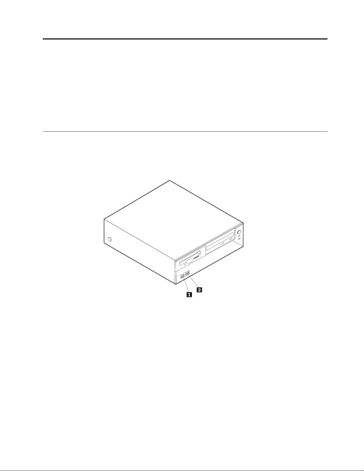
Types 8185, 8186, 8192, 8413, and 8430
The following illustration shows the locations of the connectors on the front of the
computer.
1USB connector
2USB connector
Types 8128, 8187, 8188, 8193, 8414, and 8431
The following illustration shows the locations of the connectors on the front of the
computer.
© Copyright IBM Corp. 2005 23
Page 30
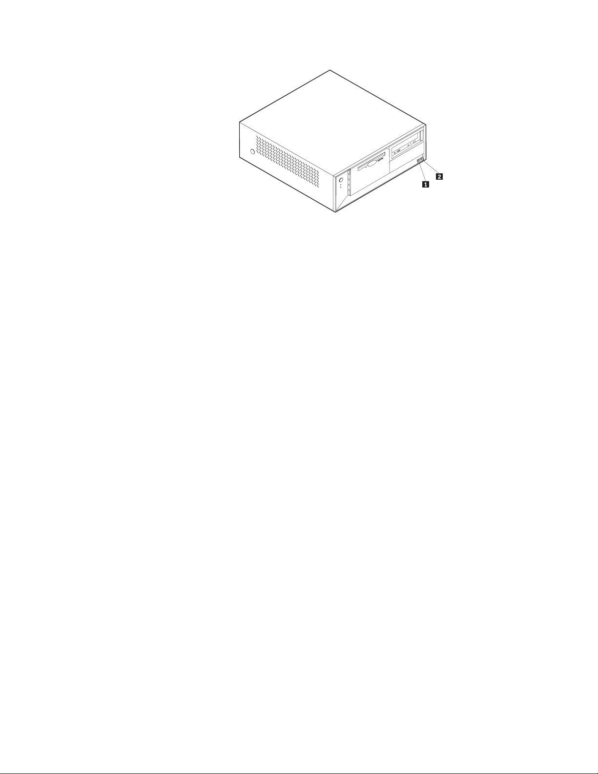
1USB connector
2USB connector
24 Hardware Maintenance Manual
Page 31

Types 8189, 8190, 8194, 8195, 8415, 8432, and 8433
The following illustration shows the locations of the connectors on the front of the
computer.
Note: Not all computer models will have the following connectors.
1IEEE 1394 connector 4USB connector
2Microphone connector 5USB connector
3Headphone connector
Types 8196 and 8197
The following illustration shows the locations of the USB connectors on the front of
the computer.
Chapter 6. Replacing FRUs 25
Page 32

1USB connector
2USB connector
26 Hardware Maintenance Manual
Page 33

Locating the connectors on the rear
Types 8185, 8186, 8192, 8413, and 8430
The following illustration shows the locations of the connectors on the rear of the
computer.
1Mouse connector 8AGP adapter connector
2Parallel connector 9Audio line out connector
3USB connectors 10Microphone connector
4Ethernet connector 11USB connectors
5Audio line in connector 12VGA monitor connector
6Power connector 13Serial connector
7PCI adapter connectors 14Keyboard connector
Note: Some connectors on the rear of the computer are color-coded to help you to
determine where to connect the cables on the computer.
Types 8128, 8187, 8188, 8193, 8414, and 8431
The following illustration shows the locations of the connectors on the rear of the
computer.
Chapter 6. Replacing FRUs 27
Page 34

1Power connector 8AGP adapter connector
2Mouse connector 9Audio line out connector
3Parallel connector 10Microphone connector
4USB connectors 11USB connectors
5Ethernet connector 12VGA monitor connector
6Audio line in connector 13Serial connector
7PCI adapter connectors 14Keyboard connector
Note: Some connectors on the rear of the computer are color-coded to help you to
determine where to connect the cables on the computer.
28 Hardware Maintenance Manual
Page 35

Types 8189, 8190, 8194, 8195, 8415, 8432, and 8433
The following illustration shows the locations of the connectors on the rear of the
computer.
1Power connector 8USB connectors
2Mouse connector 9Ethernet connector
3Keyboard connector 10Microphone connector
4Serial connector 11Audio line out connector
5Parallel connector 12Audio line in connector
6VGA monitor connector 13AGP adapter connector
7USB connectors 14PCI adapter connectors
Note: Some connectors on the rear of the computer are color-coded to help you to
determine where to connect the cables on the computer.
Types 8196 and 8197
The following illustration shows the locations of the connectors on the rear of the
computer.
Chapter 6. Replacing FRUs 29
Page 36

1Power connector 8USB connectors
2Mouse connector 9Ethernet connector
3Keyboard connector 10Microphone connector
4Serial connector 11Audio line out connector
5Parallel connector 12Audio line in connector
6VGA monitor connector 13AGP adapter connector
7USB connectors 14PCI adapter connectors
Note: Some connectors on the rear of the computer are color-coded to help you to
Removing the cover
Important: Read“Safety information” on page 247 and“Handling electrostatic
discharge-sensitive devices” on page 250 before removing the cover.
Types 8185, 8186, 8192, 8413, and 8430
1. Shut down your operating system, remove any media (diskettes, CDs, or tapes)
from the drives, and turn off all attached devices and the computer.
2. Unplug all power cords from electrical outlets.
3. Disconnect all cables attached to the computer. This includes power cords,
input/output (I/O) cables, and any other cables that are connected to the
computer.
4. Press the buttons on the sides of the computer and pivot the rear end of the
cover up toward the front of the computer.
determine where to connect the cables on the computer.
30 Hardware Maintenance Manual
Page 37

Types 8128, 8187, 8188, 8193, 8414, and 8431
1. Shut down your operating system, remove any media (diskettes, CDs, or tapes)
from the drives, and turn off all attached devices and the computer.
2. Unplug all power cords from electrical outlets.
3. Disconnect all cables attached to the computer. This includes power cords,
input/output (I/O) cables, and any other cables that are connected to the
computer.
4. Press the buttons on the sides of the computer and pivot the rear end of the
cover up toward the front of the computer.
Types 8189, 8190, 8194, 8195, 8415, 8432, and 8433
1. Shut down your operating system, remove any media (diskettes, CDs, or tapes)
from the drives, and turn off all attached devices and the computer.
2. Unplug all power cords from electrical outlets.
3. Disconnect all cables attached to the computer. This includes power cords,
input/output (I/O) cables, and any other cables that are connected to the
computer.
4. Press the cover-release button on the left side cover and remove the cover.
Chapter 6. Replacing FRUs 31
Page 38

Types 8196 and 8197
1. Shut down your operating system, remove any media (diskettes, CDs, or tapes)
from the drives, and turn off all attached devices and the computer.
2. Unplug all power cords from electrical outlets.
3. Disconnect all cables attached to the computer. This includes power cords,
input/output (I/O) cables, and any other cables that are connected to the
computer.
4. Remove the two screws at the rear of the left side cover and slide the cover to
the rear to remove.
32 Hardware Maintenance Manual
Page 39

Chapter 6. Replacing FRUs 33
Page 40

Locating components
Types 8185, 8186, 8192, 8413, and 8430
The following illustration will help you locate the various components in the
computer.
1Power supply 5Memory connector
2PCI adapter connector 6Hard disk drive
3AGP adapter connector 7Optical drive
4Support bar 8Diskette drive
34 Hardware Maintenance Manual
Page 41

Types 8128, 8187, 8188, 8193, 8414, and 8431
The following illustration will help you locate the various components in the
computer.
1Optical drive 7 Memory connectors
2USB connector 8 Microprocessor and heat sink
3USB connector 9 AGP adapter connector
4Optional drive bay 10Battery
5Hard disk drive 11PCI adapter connectors
6Diskette drive
Chapter 6. Replacing FRUs 35
Page 42

Types 8189, 8190, 8194, 8195, 8415, 8432, and 8433
The following illustration will help you locate the various components in the
computer.
1Microprocessor and heat sink 4PCI adapter
2Memory connectors 5Power supply
3AGP adapter connector
36 Hardware Maintenance Manual
Page 43

Types 8196 and 8197
The following illustration will help you locate the various components in the
computer.
1Microprocessor and heat sink 4PCI adapter connectors
2Memory connectors 5PCI adapter
3AGP adapter connector 6Power supply
Chapter 6. Replacing FRUs 37
Page 44

Identifying parts on the system board (all machine types)
1 Microprocessor 11SATA 1 IDE connector
2 Fan sink connectors 12SATA 2 IDE connector
3 Memory connector 1 13Security daughter card connector
4 Memory connector 2 14Clear CMOS/Recovery jumper
5 Memory connector 3 15Battery
6 Memory connector 4 16SCSI LED connector
7 Power connector 17PCI slots
8 Diskette drive connector 18Front panel audio connector
9 PATA primary IDE connector 19CD-ROM audio connector
10PATA secondary IDE connector 20AGP slot
Replacing memory (all machine types)
The computer has four connectors for installing dual inline memory modules
(DIMMs) that provide up to a maximum of 4.0 GB of system memory.
When installing memory modules, the following rules apply:
v System memory is divided into two channels (channel A and B). memory
connectors 1 and 2 are channel A, and memory connectors 3 and 4 are channel
B.
v If memory connectors 1 and 3 (or 2 and 4) are filled with the same technology
and size of memory, the system operates in dual channel mode.
v Use 2.5 V, 184-pin, 333 MHz double data rate synchronous dynamic random
access memory (DDR SDRAM).
v Use 128 MB, 256 MB, 512 MB or 1.0 GB (when available) memory modules in
any combination.
v Memory modules are 25.4 mm (1.0 inches) in height.
38 Hardware Maintenance Manual
Page 45

Note: Only DDR SDRAM memory modules can be used.
To replace a memory module:
1. Remove the cover. See “Removing the cover” on page 30.
2. To locate the memory connectors. See “Identifying parts on the system board
(all machine types)” on page 38.
3. Remove the memory module being replaced by opening the retaining clips as
shown.
4. Make sure the notches in the new memory module align with the tabs on the
connector. Push or insert the memory module straight down into the connector
until the retaining clips close.
5. Go to “Replacing the cover and connecting the cables” on page 63.
Replacing adapters
Types 8185, 8186, 8192, 8413, and 8430
These type computers have three expansion slots for PCI adapters and one slot
used for an AGP adapter. Adapters must be low profile. The computer supports
adapters up to 168 mm (6.6 inches) long.
1. Remove the cover. See “Removing the cover” on page 30.
Chapter 6. Replacing FRUs 39
Page 46

2. Pivot one of the drive bay latch handles toward the front of the computer and
then pivot the drive bay cage upward, as shown, until it is latched in the up
position. Repeat this procedure for the remaining drive bay.
3. Remove the support bar by pulling it outward from the computer.
4. Remove the adapter-slot-cover latch.
5. Remove the adapter being replaced.
6. Remove the new adapter from its static-protective package.
7. Install the new adapter into the appropriate slot on the system board.
8. Install the adapter-slot-cover latch.
40 Hardware Maintenance Manual
Page 47

9. Clear any cables that might impede the replacement of the drive bays.
10. Replace the support bar and pivot the two drive bays back to their original
positions.
11. Go to “Replacing the cover and connecting the cables” on page 63.
Types 8128, 8187, 8188, 8193, 8414, and 8431
These type computers have three expansion slots for PCI adapters and one slot
used for an AGP adapter. You can install an adapter up to 340 mm (13.4 inches)
long.
1. Remove the cover. See “Removing the cover” on page 30.
2. Remove the adapter-slot-cover latch.
3. Remove the adapter being replaced.
4. Remove the new adapter from its static-protective package.
5. Install the adapter into the appropriate slot on the system board.
6. Install the adapter-slot-cover latch.
7. Go to “Replacing the cover and connecting the cables” on page 63.
Chapter 6. Replacing FRUs 41
Page 48

Types 8189, 8190, 8194, 8195, 8415, 8432, and 8433
These type computers have three expansion slots for PCI adapters and one slot
used for an AGP adapter. You can install an adapter up to 228 mm (9 inches) long.
1. Remove the cover. See “Removing the cover” on page 30.
2. Remove the adapter-slot-cover latch.
3. Remove the adapter being replaced.
4. Remove the new adapter from its static-protective package.
5. Install the adapter into the appropriate slot on the system board.
6. Install the adapter-slot-cover latch.
7. Go to “Replacing the cover and connecting the cables” on page 63.
Types 8196 and 8197
These type computers have three expansion slots for PCI adapters. You can install
an adapter up to 228 mm (9 inches) long.
1. Remove the cover. See “Removing the cover” on page 30.
2. Remove the screw securing the adapter in the slot.
3. Remove the adapter being replaced.
4. Remove the new adapter from its static-protective package.
5. Install the adapter into the appropriate slot on the system board.
6. Secure the adapter with the screw as shown.
42 Hardware Maintenance Manual
Page 49

7. Go to “Replacing the cover and connecting the cables” on page 63.
Replacing internal drives
This section provides information and instructions for replacing internal drives.
v Hard disk drives
v CD drives or DVD drives
v Removable media drives
These different drives are also referred to as integrated drive electronics
Note:
(IDE) drives.
Internal drives are installed in bays. In this book, the bays are referred to as bay 1,
bay 2, and so on.
When you install an internal drive, it is important to note what type and size of
drive that you can install in each bay. Also, it is important to correctly connect the
internal drive cables to the installed drive.
Types 8185, 8186, 8192, 8413, and 8430
Drive bay information
Any bay that does not have a drive installed has a static shield and bay panel
installed.
The following illustration shows the locations of the drive bays.
Chapter 6. Replacing FRUs 43
Page 50

The following list describes some of the drives that you can install in each bay and
their height requirements:
Bay 1 and Bay 3 - Maximum height: 25.8 mm (1.0 in.)
Bay 2 - Maximum height: 43.0 mm (1.7 in.)
Removing a drive
1. Remove the cover. See “Removing the cover” on page 30.
2. Pivot the drive-bay latch handle toward the front of the computer and then
pivot the drive-bay cages upward, as shown, until latched in the upright
position.
3. Disconnect the signal cable and power supply cable from the drive being
replaced.
Note: Take note of the location of any cables you disconnect. You might have
4. For the hard disk drive and the CD drive, you can lift the tray out of the
computer.
44 Hardware Maintenance Manual
to disconnect cables to other drives to gain access to the drive you are
removing.
Page 51

5. Remove any screws that secure the drive. Not all drives have screws.
Installing a drive
1. If you are installing a parallel drive, make sure the drive is set correctly as
either a master or a slave device. Jumper the new drive the same as the drive
being replaced. Serial ATA hard disk drives do not require a master/slave
jumper.
Refer to the documentation that comes with your drive for master/slave
jumper information.
2. Install the drive into the bay and secure with any screws that were removed.
This illustration shows the hard disk drive installation.
3. Pivot the drive-bay cage back into place.
4. Continue at “Connecting the drive” on page 54.
Types 8128, 8187, 8188, 8193, 8414, and 8431
Drive bay information
Any bay that does not have a drive installed has a static shield and bay panel
installed.
Chapter 6. Replacing FRUs 45
Page 52

The following illustration shows the locations of the drive bays.
The following list describes some of the drives that you can install in each bay and
their height requirements:
Bay 1 and Bay 2- Maximum height: 43.0 mm (1.7 in.)
Bay 3 and Bay 4- Maximum height: 25.8 mm (1.0 in.)
Removing a drive
1. Remove the cover. See “Removing the cover” on page 30.
2. Pivot the drive-bay latch handle toward the front of the computer and then
pivot the appropriate drive-bay cage upward, as shown, until latched in the
upright position.
Notes:
a. Both drive-bay cages pivot in the same manner.
b. You can lift the drive-bay cages out of the chassis to make it easier to
c. Take note of the location of any cables you disconnect. You might have to
Disconnect the signal cable and power supply cable from the drive being
3.
replaced.
4. Remove any screws that secure the drive. Not all drives have screws.
46 Hardware Maintenance Manual
remove and install the drives.
disconnect cables to other drives to gain access to the drive you are
removing.
Page 53

Installing a drive
1. If you are installing a parallel drive, make sure the drive is set correctly as
either a master or a slave device. Jumper the new drive the same as the drive
being replaced. Serial ATA hard disk drives do not require a master/slave
jumper.
Refer to the documentation that comes with your drive for master/slave
jumper information.
2. Install the drive into the bay as shown.
3. Secure the new drive (if necessary) with the screws that were removed.
4. If necessary, place the drive-bay cages back into the chassis.
5. Continue at “Connecting the drive” on page 54.
Chapter 6. Replacing FRUs 47
Page 54

Types 8189, 8190, 8194, 8195, 8415, 8432, and 8433
Drive bay information
Any bay that does not have a drive installed has a static shield and bay panel
installed.
The following illustration shows the locations of the drive bays.
The following list describes some of the drives you can install in each bay and
their height requirements:
Bay 1 and Bay2 - Maximum height: 43.0 mm (1.7 in.)
Bay 3, Bay4, and Bay 5 - Maximum height: 25.8 mm (1.0 in.)
Removing the drive
1. Remove the cover. See “Removing the cover” on page 30.
2. Remove the front bezel by pushing in on the blue plastic tab at the rear of the
chassis.
3. Disconnect the signal and power cables from the drive being removed.
Note: Take note of the location of any cables you disconnect. You might have
to disconnect cables to other drives to gain access to the drive you are
removing.
48 Hardware Maintenance Manual
Page 55

4. For all drives except the hard disk drive, push in on the metal tab that secures
the drive being removed. The hard disk drive tray pivots out toward the front
of the computer for removal of the hard disk drive. See the following
illustrations.
For the hard disk drive, see the illustration below.
5. Slide the drive out the front of the computer.
Installing a drive
1. If you are installing a parallel drive, make sure the drive is set correctly as
either a master or a slave device. Jumper the new drive the same as the drive
being replaced. Serial ATA hard disk drives do not require a master/slave
jumper.
Refer to the documentation that comes with your drive for master/slave
jumper information.
2. Slide the drive into the appropriate bay.
Chapter 6. Replacing FRUs 49
Page 56

3. For bay 5 (hard disk drive), pivot the drive cage to the closed position.
4. If the front bezel was removed, replace it by aligning and pressing the bezel
into position. Continue at “Connecting the drive” on page 54.
50 Hardware Maintenance Manual
Page 57

Types 8196 and 8197
Drive bay information
The following illustration shows the locations of the drive bays.
The following table describes the drive bay height requirements.
Bay1 and bay2 - Maximum height: 43.0 mm (1.7 in.)
Bay3 and bay4 - Maximum height: 25.8 mm (1.0 in.)
Removing a drive
1. Remove the cover. See “Removing the cover” on page 30.
Chapter 6. Replacing FRUs 51
Page 58

2. If you are removing the hard disk drive or diskette drive, remove the front
bezel by releasing the four plastic tabs inside the chassis and pressing down on
the top of the bezel.
3. Disconnect the signal and power cables from the drive being removed.
52 Hardware Maintenance Manual
Page 59

Note: Take note of the location of any cables you disconnect. You might have
to disconnect cables to other drives to gain access to the drive you are
removing.
4. Remove the screws that secure the drive being removed.
Note: The hard disk drive is secured by two screws in the side and two at the
bottom of the drive.
5. Slide the drive out the front of the computer.
Note: This illustration shows the hard disk drive being removed. All drives are
removed in the same manner. However, it is only necessary to remove
the front bezel when removing the hard disk drive or diskette drive.
Installing a drive
1. If you are installing a parallel drive, make sure the drive is set correctly as
either a master or a slave device. Jumper the new drive the same as the drive
being replaced. Serial ATA hard disk drives do not require a master/slave
jumper.
Refer to the documentation that comes with your drive for master/slave
jumper information.
2. Install the drive into the bay. Align the screw holes and install two screws to
secure the drive.
Chapter 6. Replacing FRUs 53
Page 60

Note: This illustration shows a CD drive installation. The hard disk drive and
diskette drive is installed in the same manner except that the front bezel
is not in place.
3. If the front bezel was removed, replace it by aligning the four plastic tabs and
pressing the bezel into position.
4. Go to “Connecting the drive.”
Connecting the drive
Each drive requires two cables; a power cable from the power supply and a signal
cable that connects the drive to the system board. See “Identifying parts on the
system board (all machine types)” on page 38.
There are two types of hard disk drives; parallel ATA and serial ATA. Each one is
connected to a different location on the system board. See “Parallel ATA hard disk
drive” and “Serial ATA hard disk drive” on page 55.
Other drives, such as a CD drive, connect to either the primary or secondary PATA
connector.
The diskette drive connects to the diskette drive connector.
Parallel ATA hard disk drive
54 Hardware Maintenance Manual
Page 61

1. Locate an available PATA IDE connector on the three-connector signal cable
attached to either the PATA primary IDE or PATA secondary IDE connector on
the system board. See “Identifying parts on the system board (all machine
types)” on page 38.
2. Connect one end of the signal cable to the drive and the other to an available
PATA IDE connector on the system board.
3. Connect a power connector to the drive.
4. Go to “Replacing the cover and connecting the cables” on page 63.
Serial ATA hard disk drive
A serial hard disk drive can be connected to either the SATA 1 IDE or SATA 2 IDE
connector.
1. Locate the signal cable for the new drive.
2. Locate an available SATA IDE connector on the system board. See “Identifying
parts on the system board (all machine types)” on page 38.
3. Connect one end of the signal cable to the drive and the other to an available
SATA IDE connector on the system board.
4. Connect a power connector to the drive.
5. Go to “Replacing the cover and connecting the cables” on page 63.
CD drive, DVD drive, CD/RW drive, or DVD/CD/RW combo drive
1. Locate the three-connector signal cable that comes with the computer or with
the new drive.
2. Locate the PATA primary and secondary IDE connectors on the system board.
See “Identifying parts on the system board (all machine types)” on page 38.
3. Connect one end of the signal cable to the drive and the other to the
appropriate PATA IDE connector on the system board. To reduce electronic
noise, use the connectors at the end of the cable only.
4. Connect the power connector to the drive.
5. If you have a CD-ROM audio cable, connect it to the drive and to the system
board. See “Identifying parts on the system board (all machine types)” on page
38.
6. Go to “Replacing the cover and connecting the cables” on page 63.
Diskette drive
1. Locate the diskette drive connector on the system board. See “Identifying parts
on the system board (all machine types)” on page 38.
2. Connect one end of the signal cable to the drive and the other to the diskette
drive connector on the system board.
Chapter 6. Replacing FRUs 55
Page 62

3. Connect the power connector to the drive.
4. Go to “Replacing the cover and connecting the cables” on page 63.
Replacing the battery (all machine types)
The computer has a special type of memory that maintains the date, time, and
settings for built-in features, such as parallel-port assignments (configuration). A
battery keeps this information active when you turn off the computer. If the
battery fails, the date, time, and configuration information (including passwords)
are lost. An error message is displayed when you turn on the computer.
Refer to “Safety notices (multi-lingual translations)” on page 251 for information
about replacing and disposing of the battery.
To change the battery:
1. Turn off the computer and all attached devices.
2. Remove the cover. See “Removing the cover” on page 30.
3. Locate the battery. See “Identifying parts on the system board (all machine
types)” on page 38.
4. If necessary, remove any adapters that impede access to the battery. See
“Replacing adapters” on page 39 for more information.
5. Remove the old battery.
6. Install the new battery.
7. Replace any adapters that were removed to gain access to the battery. See
“Replacing adapters” on page 39 for instructions for replacing adapters.
8. Replace the cover, and plug in the power cord. See “Replacing the cover and
connecting the cables” on page 63.
Note: When the computer is turned on for the first time after battery
replacement, an error message might be displayed. This is normal after
replacing the battery.
9. Turn on the computer and all attached devices.
10. Use the IBM Setup Utility program to set the date and time and any
passwords. See Chapter 5, “IBM Setup Utility program,” on page 19.
56 Hardware Maintenance Manual
Page 63

Replacing the power supply
Types 8185, 8186, 8192, 8413, and 8430
Before performing any removals or replacements, turn off the computer and
peripheral devices and disconnect all external cables and power cords.
To remove the power supply, do the following:
1. Turn off the computer and peripheral devices and disconnect all external cables
and power cords; then, remove the cover. See “Removing the cover” on page
30.
2. Disconnect all power supply cables from the system board and the drives. See
“Identifying parts on the system board (all machine types)” on page 38.
3. Remove the two screws that hold the power supply in place.
4. Lift the power supply out.
To replace the power supply, do the following:
1. Install the new power supply and insert the two screws that hold the power
supply in place.
2. Reconnect all power supply cables to the system board and the drives. See
“Identifying parts on the system board (all machine types)” on page 38.
3. Go to “Replacing the cover and connecting the cables” on page 63.
Types 8128, 8187, 8188, 8193, 8414, and 8431
Before performing any removals or replacements, turn off the computer and
peripheral devices and disconnect all external cables and power cords.
To remove the power supply, do the following:
1. Turn off the computer and peripheral devices and disconnect all external cables
and power cords; then, remove the cover. See “Removing the cover” on page
30.
2. Disconnect all power supply cables from the system board and the drives. See
“Identifying parts on the system board (all machine types)” on page 38.
3. Remove the four screws that hold the power supply in place.
4. Lift the power supply out.
Chapter 6. Replacing FRUs 57
Page 64

To replace the power supply, do the following:
1. Install the new power supply and insert the four screws that hold the power
supply in place.
2. Reconnect all power supply cables to the system board and the drives. See
“Identifying parts on the system board (all machine types)” on page 38.
3. Go to “Replacing the cover and connecting the cables” on page 63.
Types 8189, 8190, 8194, 8195, 8196, 8197, 8415, 8432, and 8433
Before performing any removals or replacements, turn off the computer and
peripheral devices and disconnect all external cables and power cords.
To remove the power supply, do the following:
1. Turn off the computer and peripheral devices and disconnect all external cables
and power cords; then, remove the cover. See “Removing the cover” on page
30.
2. Disconnect all power supply cables from the system board and the drives. See
“Identifying parts on the system board (all machine types)” on page 38.
3. Remove the four screws that hold the power supply in place.
4. Lift the power supply out.
58 Hardware Maintenance Manual
Page 65

To replace the power supply, do the following:
1. Install the new power supply and insert the four screws that hold the power
supply in place.
2. Reconnect all power supply cables to the system board and the drives. See
“Identifying parts on the system board (all machine types)” on page 38.
3. Go to “Replacing the cover and connecting the cables” on page 63.
Replacing a microprocessor (all machine types)
To remove the microprocessor, do the following:
1. Turn off the computer and peripheral devices and disconnect all external cables
and power cords; then, remove the cover. See “Removing the cover” on page
30.
2. Remove any air baffles or ducts that cover the microprocessor.
3. Disconnect the heat sink fan cable from the system board. Refer to “Identifying
parts on the system board (all machine types)” on page 38.
Chapter 6. Replacing FRUs 59
Page 66

4. Loosen the two captured screws 3 holding the fan and heat sink in place, and
pivot them to the side.
5. To remove the fan and heat sink 1 from the microprocessor 2, gently twist
the fan and heat sink to break the seal formed by the thermal grease and
remove.
Note: If the thermal grease seal cannot be broken, you may want to start up
the system to heat the processor and loosen the thermal grease.
6. Place the heat sink on a clean work surface.
7. Take notice of the orientation of the beveled corner on the microprocessor. This
is important when reinstalling the microprocessor on the system board.
8. Release the microprocessor from the system board by pulling outward and
lifting the small handle on the microprocessor socket to its maximum vertical
position. Carefully lift the microprocessor off the socket.
To replace the microprocessor, do the following:
1. Make sure that the microprocessor socket handle is fully in the vertical
position. Otherwise the microprocessor pins might be damaged when installing
the microprocessor.
2. Position the microprocessor so that the pins are aligned with the socket and
with the beveled corner in the correct orientation.
3. Lower the handle until it is fully in the down position and locked into the
socket. This secures the microprocessor in the socket.
4. Remove the cleaning pad from its package and use the cleaning pad to wipe
the thermal grease from the bottom of the heat sink.
Notes:
a. The cleaning pad and thermal grease are separate FRUs and are not
included with the system board or microprocessor FRUs. These must be
ordered separately and shipped along with the FRUs being replaced.
b. Be sure that all of the thermal grease is removed.
Use the thermal grease syringe to place 16 uniformly spaced dots of 0.01ML
5.
each on the top of the microprocessor.
60 Hardware Maintenance Manual
Page 67

Microprocessor
0.01 ML of
thermal grease
Note: 0.01ML is one tick mark on the syringe. If the grease is properly applied,
approximately half (0.22ML) of the grease will remain in the syringe.
6. Place the fan and heat sink into position on the microprocessor.
7. When tightening the screws that clamp the heat sink, do not overtighten.
Tighten the clamp screws evenly by tightening one side some and then the
other until they are both snug.
8. Reconnect the fan to the system board connector.
9. Go to “Replacing the cover and connecting the cables” on page 63.
Replacing the system board (all machine types)
Note: The computer might look slightly different than the following illustrations
To remove the system board:
1. Turn off the computer and peripheral devices and disconnect all external cables
and power cords; then, remove the cover. See “Removing the cover” on page
30.
2. Disconnect all cables connected to the system board.
3. Remove the screws that secure the system board to the chassis and lift out the
system board.
Chapter 6. Replacing FRUs 61
Page 68

Types 8185, 8186, 8192, 8413, and 8430
Types 8128, 8187, 8188, 8193, 8414, and 8431
62 Hardware Maintenance Manual
Page 69

Types 8189, 8190, 8194, 8195, 8196, 8197, 8415, 8432, and 8433
4. Remove the memory modules from the system board. Refer to “Replacing
memory (all machine types)” on page 38.
5. Remove the microprocessor from the system board. Refer to “Replacing a
microprocessor (all machine types)” on page 59.
To replace the system board:
1. Install the microprocessor on the new system board. Refer to “Replacing a
microprocessor (all machine types)” on page 59.
2. Install the memory modules on the new system board. Refer to “Replacing
memory (all machine types)” on page 38.
3. Place the new the system board into the chassis and install the screws that
secure the system board to the chassis.
4. Reconnect all cables that connect to the system board. Refer to “Identifying
parts on the system board (all machine types)” on page 38.
5. Go to “Replacing the cover and connecting the cables.”
Replacing the cover and connecting the cables
Types 8185, 8186, 8192, 8413, and 8430
After replacing FRUs, you need to install any removed parts, replace the cover, and
reconnect cables, including telephone lines and power cords. Also, depending on
the option that is installed, you might need to confirm the updated information in
the IBM Setup Utility program.
To replace the cover and connect cables to the computer:
1. Ensure that all components have been reassembled correctly and that no tools
or loose screws are left inside the computer.
2. Clear any cables that might impede the replacement of the cover.
Chapter 6. Replacing FRUs 63
Page 70

3. Position the cover over the chassis and pivot it down over the computer until it
snaps into place.
4. Reconnect the external cables and power cords to the computer.
5. If you have replaced the system board, you must update (flash) the BIOS. See
“Flash update procedures” on page 113.
6. To update the configuration, see Chapter 5, “IBM Setup Utility program,” on
page 19.
Types 8128, 8187, 8188, 8193, 8414, and 8431
After replacing FRUs, you need to install any removed parts, replace the cover, and
reconnect any cables, including telephone lines and power cords. Also, depending
on the option that is installed, you might need to confirm the updated information
in the IBM Setup Utility program.
To replace the cover and connect cables to the computer:
1. Ensure that all components have been reassembled correctly and that no tools
or loose screws are left inside the computer.
2. Clear any cables that might impede the replacement of the cover.
3. Position the cover over the chassis and pivot it down over the computer until it
snaps into place.
64 Hardware Maintenance Manual
Page 71

4. Reconnect the external cables and power cords to the computer.
5. If you have replaced the system board, you must update (flash) the BIOS. See
“Flash update procedures” on page 113.
6. To update the configuration, see Chapter 5, “IBM Setup Utility program,” on
page 19.
Types 8189, 8190, 8194, 8195, 8415, 8432, and 8433
After replacing FRUs, you need to install any removed parts, replace the cover, and
reconnect any cables, including telephone lines and power cords. Also, depending
on the option that is installed, you might need to confirm the updated information
in the IBM Setup Utility program.
To replace the cover and connect cables to the computer:
1. Ensure that all components have been reassembled correctly and that no tools
or loose screws are left inside the computer.
2. Clear any cables that might impede the replacement of the cover.
3. Position the cover on the chassis so that the rail guides on the bottom of the
cover engage the rails and push the cover closed until it latches.
Chapter 6. Replacing FRUs 65
Page 72

4. Reconnect the external cables and power cords to the computer.
5. If you have replaced the system board, you must update (flash) the BIOS. See
“Flash update procedures” on page 113.
6. To update the configuration, see Chapter 5, “IBM Setup Utility program,” on
page 19.
When the power cord is first plugged in, the computer might appear to turn
Note:
on for a few seconds and then turn off. This is a normal sequence to enable
the computer to initialize.
Types 8196 and 8197
After replacing FRUs, you need to install any removed parts, replace the cover, and
reconnect any cables, including telephone lines and power cords. Also, depending
on the option that is installed, you might need to confirm the updated information
in the IBM Setup Utility program.
To replace the cover and connect cables to the computer:
1. Ensure that all components have been reassembled correctly and that no tools
or loose screws are left inside the computer.
2. Clear any cables that might impede the replacement of the cover.
3. Position the cover on the chassis so that the guides on the top and bottom of
the cover engage the chassis and push the cover to the closed position. Insert
the screws that secure the cover.
66 Hardware Maintenance Manual
Page 73

4. Reconnect the external cables and power cords to the computer.
5. If you have replaced the system board, you must update (flash) the BIOS. See
“Flash update procedures” on page 113.
6. To update the configuration, see Chapter 5, “IBM Setup Utility program,” on
page 19.
When the power cord is first plugged in, the computer might appear to turn
Note:
on for a few seconds and then turn off. This is a normal sequence to enable
the computer to initialize.
Chapter 6. Replacing FRUs 67
Page 74

68 Hardware Maintenance Manual
Page 75

Chapter 7. Symptom-to-FRU Index
The Symptom-to-FRU index lists error symptoms and possible causes. The most
likely cause is listed first. Always begin with Chapter 3, “General Checkout,” on
page 11. This index can also be used to help you decide which FRUs to have
available when servicing a computer. If you are unable to correct the problem
using this index, go to “Undetermined problems” on page 109.
Notes:
v If you have both an error message and an incorrect audio response, diagnose the error
message first.
v If you cannot run the diagnostic tests or you get a diagnostic error code when running a
test, but did receive a POST error message, diagnose the POST error message first.
v If you did not receive any error message, look for a description of your error symptoms
in the first part of this index.
v Check the hard disk drive jumper settings before you replace a hard disk drive.
Hard disk drive boot error
A hard disk drive boot error (error codes 1962 and I999030X) can have the
following causes.
Error FRU/Action
The start-up drive is not in the boot
sequence in configuration.
No operating system installed on the boot
drive.
The boot sector on the start-up drive is
corrupted.
The drive is defective. Replace the hard disk drive.
Check the configuration and ensure the
start-up drive is in the boot sequence.
Install an operating system on the boot
drive.
The drive must be formatted, do the
following:
1. Attempt to access and recover (back-up)
the failing hard disk drive.
2. Using the operating systems programs,
format the hard disk drive.
© Copyright IBM Corp. 2005 69
Page 76

Power Supply Errors
If the power-on indicator is not on, the power supply fan is not running, or the
computer will not power-off, use the following procedures.
Check/Verify FRU/Action
Check the following for proper installation.
v Power Cord
v On/Off Switch assembly
v Power/LED connector
v System Board Power Supply connectors
v Microprocessor(s)
Check the power cord for continuity. Power Cord
Check the power supply voltages See “Power supply
Diagnostic error codes
Refer to the following diagnostic error codes when using the diagnostic tests. See
Chapter 4, “IBM Enhanced Diagnostics,” on page 15 for information about the
Diagnostic programs.
In the following index, X can represent any number.
Diagnostic Error Code FRU/Action
000-000-XXX
BIOS Test Passed
000-002-XXX
BIOS Timeout
000-024-XXX
BIOS Addressing test failure
000-025-XXX
BIOS Checksum Value error
000-026-XXX
FLASH data error
000-027-XXX
BIOS Configuration/Setup error
000-034-XXX
BIOS Buffer Allocation failure
Reseat connectors (see
“Identifying parts on
the system board (all
machine types)” on
page 38.
connectors” on page
110.
1. No action
1. Flash the system
2. System board
1. Flash the system
2. System board
1. Flash the system
2. Boot block
3. System board
1. Flash the system
2. Boot block
3. System board
1. Run Setup
2. Flash the system
3. Boot block
4. System board
1. Reboot the system
2. Flash the system
3. Run memory test
4. System board
70 Hardware Maintenance Manual
Page 77

Diagnostic Error Code FRU/Action
000-035-XXX
BIOS Reset Condition detected
000-036-XXX
BIOS Register error
1. Flash the system
2. System board
1. Flash the system
2. Boot block
3. System board
000-038-XXX
BIOS Extension failure
1. Flash the system
2. Adapter card
3. System board
000-039-XXX
BIOS DMI data error
000-195-XXX
BIOS Test aborted by user
000-196-XXX
BIOS test halt, error threshold exceeded
000-197-XXX
BIOS test warning
1. Flash the system
2. System board
1. Information
2. Re-start the test, if necessary
1. Press F3 to review the log file
2. Re-start the test to reset the log file
1. Make sure the component that is called
out is connected and/or enabled
2. Re-run test
3. Component that is called out in warning
statement
4. Component under test
000-198-XXX
BIOS test aborted
1. If a component is called out, make sure
it is connected and/or enabled
2. Flash the system and re-test
3. Go to “Undetermined problems” on page
109.
000-199-XXX
BIOS test failed, cause unknown
1. Go to “Undetermined problems” on
page 109.
2. Flash the system and re-test
3. Replace component under function test
000-250-XXX
BIOS APM failure
000-270-XXX
BIOS ACPI failure
001-000-XXX
1. Flash the system
2. System board
1. Flash the system
2. System board
No action
System Test Passed
001-00X-XXX
System board
System Error
001-01X-XXX
System board
System Error
001-024-XXX
System board
System Addressing test failure
001-025-XXX
System Checksum Value error
1. Flash the system
2. System board
Chapter 7. Symptom-to-FRU Index 71
Page 78

Diagnostic Error Code FRU/Action
001-026-XXX
System FLASH data error
001-027-XXX
System Configuration/Setup error
1. Flash the system
2. System board
1. Run Setup
2. Flash the system
3. System board
001-032-XXX
System board
System Device Controller failure
001-034-XXX
System Device Buffer Allocation failure
1. Reboot the system
2. Flash the system
3. Run memory test
4. System board
001-035-XXX
System board
System Device Reset condition detected
001-036-XXX
System board
System Register error
001-038-XXX
System Extension failure
001-039-XXX
System DMI data structure error
001-040-XXX
System IRQ failure
001-041-XXX
System DMA failure
001-195-XXX
System Test aborted by user
001-196-XXX
System test halt, error threshold exceeded
001-197-XXX
System test warning
1. Adapter card
2. System board
1. Flash the system
2. System board
1. Power-off/on system and re-test
2. System board
1. Power-off/on system and re-test
2. System board
1. Information
2. Re-start the test, if necessary
1. Press F3 to review the log file
2. Re-start the test to reset the log file
1. Make sure the component that is called
out is connected and/or enabled
2. Re-run test
3. Component that is called out in warning
statement
4. Component under test
001-198-XXX
System test aborted
1. If a component is called out, make sure
it is connected and/or enabled
2. Flash the system and re-test
3. Go to “Undetermined problems” on page
109
001-199-XXX
System test failed, cause unknown
1. Go to “Undetermined problems” on page
109
2. Flash the system and re-test
3. Replace component under function test
001-250-XXX
System ECC error
1. System board
72 Hardware Maintenance Manual
Page 79

Diagnostic Error Code FRU/Action
001-254-XXX
System board
001-255-XXX
001-256-XXX
001-257-XXX
System DMA error
001-260-XXX
System board
001-264-XXX
System IRQ error
001-268-XXX
System IRQ1 failure
001-269-XXX
System IRQ2 failure
001-270-XXX
System IRQ3 failure
001-271-XXX
System IRQ4 failure
001-272-XXX
System IRQ5 failure
001-273-XXX
System IRQ6
(diskette drive) failure
1. Device on IRQ1
2. System board
1. Device on IRQ2
2. System board
1. Device on IRQ3
2. System board
1. Device on IRQ4
2. System board
1. Device on IRQ5
2. System board
1. Diskette Cable
2. Diskette drive
3. System board
001-274-XXX
System IRQ7 failure
001-275-XXX
System IRQ8 failure
001-276-XXX
System IRQ9 failure
001-277-XXX
System IRQ10 failure
001-278-XXX
System IRQ11 failure
001-279-XXX
System IRQ12 failure
001-280-XXX
System IRQ13 failure
001-281-XXX
System IRQ14
(hard disk drive) failure
1. Device on IRQ7
2. System board
1. Device on IRQ8
2. System board
1. Device on IRQ9
2. System board
1. Device on IRQ10
2. System board
1. Device on IRQ11
2. System board
1. Device on IRQ12
2. System board
1. Device on IRQ13
2. System board
1. Hard disk drive cable
2. Hard disk drive
3. System board
001-282-XXX
System IRQ15 failure
1. Device on IRQ15
2. System board
Chapter 7. Symptom-to-FRU Index 73
Page 80

Diagnostic Error Code FRU/Action
001-286-XXX
System board
001-287-XXX
001-288-XXX
System Timer failure
001-292-XXX
System CMOS
RAM error
001-293-XXX
System CMOS Battery
001-298-XXX
System RTC date/time update failure
001-299-XXX
System RTC periodic interrupt failure
001-300-XXX
System RTC Alarm failure
001-301-XXX
System RTC Century byte error
005-000-XXX
1. Run Setup and re-test
2. System board
1. Battery
2. System board
1. Flash the system
2. System board
1. System board
1. System board
1. Flash the system
2. System board
No action
Video Test Passed
005-00X-XXX
Video error
005-010-XXX
005-011-XXX
005-012-XXX
1. Video card, if installed
2. System board
1. Video card, if installed
2. System board
005-013-XXX
Video Signal failure
005-016-XXX
Video Simple Pattern
test failure
1. Video Ram
2. Video card, if installed
3. System board
005-024-XXX
Video Addressing test failure
005-025-XXX
Video Checksum Value error
005-027-XXX
Video Configuration/Setup error
1. Video card, if installed
2. System board
1. Video card, if installed
2. System board
1. Run Setup
2. Video drivers update
3. Video card, if installed
4. System board
005-031-XXX
Video Device Cable failure
1. Video cable
2. Monitor
3. Video card, if installed
4. System board
005-032-XXX
Video Device Controller failure
1. Video card, if installed
2. System board
74 Hardware Maintenance Manual
Page 81

Diagnostic Error Code FRU/Action
005-036-XXX
Video Register error
005-038-XXX
System BIOS extension failure
005-040-XXX
Video IRQ failure
005-195-XXX
Video Test aborted by user
005-196-XXX
Video test halt, error threshold exceeded
005-197-XXX
Video test warning
1. Video card, if installed
2. System board
1. Video card, if installed
2. System board
1. Video card, if installed
2. System board
1. Information
2. Re-start the test, if necessary
1. Press F3 to review the log file
2. Re-start the test to reset the log file
1. Make sure the component that is called
out is connected and/or enabled
2. Re-run test
3. Component that is called out in warning
statement
4. Component under test
005-198-XXX
Video test aborted
1. If a component is called out, make sure
it is connected and/or enabled
2. Flash the system and re-test
3. Go to “Undetermined problems” on page
109
005-199-XXX
Video test failed, cause unknown
1. Go to “Undetermined problems” on page
109
2. Flash the system and re-test
3. Replace component under function test
005-2XX-XXX
005-3XX-XXX
Video subsystem error
006-000-XXX
1. Video card, if installed
2. System board
No action
Diskette interface Test Passed
006-0XX-XXX
Diskette interface error
1. Diskette drive Cable
2. Diskette drive
3. System board
006-195-XXX
Diskette interface Test aborted by user
006-196-XXX
Diskette interface test halt, error threshold
exceeded
006-197-XXX
Diskette interface test warning
1. Information
2. Re-start the test, if necessary
1. Press F3 to review the log file
2. Re-start the test to reset the log file
1. If a component is called out, make sure
it is connected and/or enabled
2. Re-run test
3. Component that is called out in warning
statement
4. Component under test
Chapter 7. Symptom-to-FRU Index 75
Page 82

Diagnostic Error Code FRU/Action
006-198-XXX
Diskette interface test aborted
1. If a component is called out, make sure
it is connected and/or enabled
2. Flash the system and re-test
3. Go to “Undetermined problems” on page
109
006-199-XXX
Diskette interface test failed, cause unknown
1. Go to “Undetermined problems” on page
109
2. Flash the system and re-test
3. Replace component under function test
006-25X-XXX
Diskette interface Error
1. Diskette drive cable
2. Diskette drive
3. System board
011-000-XXX
Serial port Interface Test Passed
011-001-XXX
Serial port Presence
1. No action
1. Remove external serial device, if
present
2. Run setup, enable port
3. System board
011-002-XXX
System board
011-003-XXX
Serial port Timeout/Parity error
011-013-XXX
System board
011-014-XXX
Serial port Control Signal/Loopback test
failure
011-015-XXX
Serial port External Loopback failure
011-027-XXX
Serial port Configuration/Setup error
1. Wrap plug
2. System board
1. Run Setup, enable port
2. Flash the system
3. System board
011-03X-XXX
System board
011-04X-XXX
Serial port failure
011-195-XXX
Serial port Test aborted by user
011-196-XXX
Serial port test halt, error threshold exceeded
011-197-XXX
Serial port test warning
1. Information
2. Re-start the test, if necessary
1. Press F3 to review the log file
2. Re-start the test to reset the log file
1. Make sure the component that is called
out is connected and/or enabled
2. Re-run test
3. Component that is called out in warning
statement
4. Component under test
76 Hardware Maintenance Manual
Page 83

Diagnostic Error Code FRU/Action
011-198-XXX
Serial port test aborted
1. If a component is called out, make sure
it is connected and/or enabled
2. Flash the system and re-test
3. Go to “Undetermined problems” on page
109
011-199-XXX
Serial port test failed, cause unknown
1. Go to “Undetermined problems” on page
109
2. Flash the system and re-test
3. Replace component under function test
011-2XX-XXX
Serial port signal failure
014-000-XXX
1. External serial device
2. System board
No action
Parallel port Interface Test Passed
014-001-XXX
Parallel port Presence
1. Remove external parallel device, if
present
2. Run setup, enable port
3. System board
014-002-XXX
System board
014-003-XXX
Parallel port Timeout/Parity error
014-013-XXX
System board
014-014-XXX
Parallel port Control Signal/Loopback test
failure
014-015-XXX
Parallel port External Loopback failure
014-027-XXX
Parallel port Configuration/Setup error
1. Wrap plug
2. System board
1. Run Setup, enable port
2. Flash the system
3. System board
014-03X-XXX
System board
014-04X-XXX
Parallel port failure
014-195-XXX
Parallel port Test aborted by user
014-196-XXX
Parallel port test halt, error threshold
exceeded
014-197-XXX
Parallel port test warning
1. Information
2. Re-start the test, if necessary
1. Press F3 to review the log file
2. Re-start the test to reset the log file
1. Make sure the component that is called
out is connected and/or enabled
2. Re-run test
3. Component that is called out in warning
statement
4. Component under test
Chapter 7. Symptom-to-FRU Index 77
Page 84

Diagnostic Error Code FRU/Action
014-198-XXX
Parallel port test aborted
1. If a component is called out, make sure
it is connected and/or enabled
2. Flash the system and re-test
3. Go to “Undetermined problems” on page
109
014-199-XXX
Parallel port test failed, cause unknown
1. Go to “Undetermined problems” on page
109
2. Flash the system and re-test
3. Replace component under function test
014-2XX-XXX
014-3XX-XXX
Parallel port failure
015-000-XXX
USB port Interface Test Passed
015-001-XXX
USB port Presence
015-002-XXX
USB port Timeout
015-015-XXX
USB port External Loopback failure
015-027-XXX
USB port Configuration/Setup error
015-032-XXX
1. External parallel device
2. System board
1. No action
1. Remove USB device(s) and re-test
2. System board
1. Remove USB device(s) and re-test
2. System board
1. Remove USB device(s) and re-test
2. System board
1. Flash the system
2. System board
System board
USB port Device Controller failure
015-034-XXX
USB port buffer
allocation failure
1. Reboot the system
2. Flash the system
3. Run memory test
4. System board
015-035-XXX
USB port Reset condition detected
015-036-XXX
1. Remove USB device(s) and re-test
2. System board
System board
USB port Register error
015-040-XXX
USB port IRQ failure
1. Run setup and check for conflicts
2. Flash the system
3. System board
015-195-XXX
USB port Test aborted by user
015-196-XXX
USB port test halt, error threshold exceeded
1. Information
2. Re-start the test, if necessary
1. Press F3 to review the log file
2. Re-start the test to reset the log file
78 Hardware Maintenance Manual
Page 85

Diagnostic Error Code FRU/Action
015-197-XXX
USB port test warning
1. Make sure the component that is called
out is connected and/or enabled
2. Re-run test
3. Component that is called out in warning
statement
4. Component under test
015-198-XXX
USB port test aborted
1. If a component is called out, make sure
it is connected and/or enabled
2. Flash the system and re-test
3. Go to “Undetermined problems” on page
109
015-199-XXX
USB port test failed, cause unknown
1. Go to “Undetermined problems” on page
109
2. Flash the system and re-test
3. Replace component under function test
018-000-XXX
No action
PCI Card Test Passed
018-0XX-XXX
PCI Card Failure
018-195-XXX
PCI Card Test aborted by user
1. Riser card, if installed
2. System board
1. PCI card
2. Information
3. Re-start the test, if necessary
018-196-XXX
PCI Card test halt, error threshold exceeded
018-197-XXX
PCI Card test warning
1. Press F3 to review the log file
2. Re-start the test to reset the log file
1. Make sure the component that is called
out is connected and/or enabled
2. Re-run test
3. Component that is called out in warning
statement
4. Component under test
018-198-XXX
PCI Card test aborted
1. Make sure the component that is called
out is connected and/or enabled
2. Flash the system and re-test
3. Go to “Undetermined problems” on page
109
018-199-XXX
PCI Card test failed, cause unknown
1. Go to “Undetermined problems” on page
109
2. Flash the system and re-test
3. Replace component under function test
018-250-XXX
PCI Card Services error
1. PCI card
2. Riser card, if installed
3. System board
020-000-XXX
No action
PCI Interface Test Passed
Chapter 7. Symptom-to-FRU Index 79
Page 86

Diagnostic Error Code FRU/Action
020-0XX-XXX
PCI Interface error
1. PCI card
2. Riser card, if installed
3. System board
020-195-XXX
PCI Test aborted by user
020-196-XXX
PCI test halt, error threshold exceeded
020-197-XXX
PCI test warning
1. Information
2. Re-start the test, if necessary
1. Press F3 to review the log file
2. Re-start the test to reset the log file
1. Make sure the component that is called
out is connected and/or enabled
2. Re-run test
3. Component that is called out in warning
statement
4. Component under test
020-198-XXX
PCI test aborted
1. If a component is called out, make sure
it is connected and/or enabled
2. Flash the system and re-test
3. Go to “Undetermined problems” on page
109
020-199-XXX
PCI test failed, cause unknown
1. Go to “Undetermined problems” on page
109
2. Flash the system and re-test
3. Replace component under function test
020-262-XXX
PCI
system error
1. PCI card
2. Riser card, if installed
3. System board
025-000-XXX
IDE interface Test Passed
025-00X-XXX
025-01X-XXX
IDE interface failure
1. No action
1. IDE signal cable
2. Check power supply
3. IDE device
4. System board
025-027-XXX
IDE interface Configuration/Setup error
1. IDE signal cable
2. Flash the system
3. IDE device
4. System board
025-02X-XXX
025-03X-XXX
025-04X-XXX
IDE Interface failure
1. IDE signal cable
2. Check power supply
3. IDE device
4. System board
025-195-XXX
IDE interface Test aborted by user
025-196-XXX
IDE interface test halt, error threshold
exceeded
1. Information
2. Re-start the test, if necessary
1. Press F3 to review the log file
2. Re-start the test to reset the log file
80 Hardware Maintenance Manual
Page 87

Diagnostic Error Code FRU/Action
025-197-XXX
IDE interface test warning
1. Make sure the component that is called
out is connected and/or enabled
2. Re-run test
3. Component that is called out in warning
statement
4. Component under test
025-198-XXX
IDE interface test aborted
1. If a component is called out, make sure
it is connected and/or enabled
2. Flash the system and re-test
3. Go to “Undetermined problems” on page
109
025-199-XXX
IDE interface test failed, cause unknown
1. Go to “Undetermined problems” on page
109
2. Flash the system and re-test
3. Replace component under function test
030-000-XXX
No action
SCSI interface Test Passed
030-00X-XXX
030-01X-XXX
SCSI interface failure
1. SCSI signal cable
2. Check power supply
3. SCSI device
4. SCSI adapter card, if installed
5. System board
030-027-XXX
SCSI interface Configuration/Setup error
1. SCSI signal cable
2. Flash the system
3. SCSI device
4. SCSI adapter card, if installed
5. System board
030-03X-XXX
030-04X-XXX
SCSI interface error
1. SCSI signal cable
2. Check power supply
3. SCSI device
4. SCSI adapter card, if installed
5. installed System board
030-195-XXX
SCSI interface Test aborted by user
030-196-XXX
SCSI interface test halt, error threshold
exceeded
030-197-XXX
SCSI interface test warning
1. Information
2. Re-start the test, if necessary
1. Press F3 to review the log file
2. Re-start the test to reset the log file
1. Make sure the component that is called
out is connected and/or enabled
2. Re-run test
3. Component that is called out in warning
statement
4. Component under test
Chapter 7. Symptom-to-FRU Index 81
Page 88

Diagnostic Error Code FRU/Action
030-198-XXX
SCSI interface test aborted
1. If a component is called out, make sure
it is connected and/or enabled
2. Flash the system and re-test
3. Go to “Undetermined problems” on page
109
030-199-XXX
SCSI interface test failed, cause unknown
1. Go to “Undetermined problems” on page
109
2. Flash the system and re-test
3. Replace component under function test
035-000-XXX
No action
RAID interface Test Passed
035-0XX-XXX
RAID interface Failure
1. RAID signal cable
2. RAID device
3. RAID adapter card, if installed
4. System board
035-195-XXX
RAID interface Test aborted by user
035-196-XXX
RAID interface test halt, error threshold
exceeded
035-197-XXX
RAID interface test warning
1. Information
2. Re-start the test, if necessary
1. Press F3 to review the log file
2. Re-start the test to reset the log file
1. Make sure the component that is called
out is connected and/or enabled
2. Re-run test
3. Component that is called out in warning
statement
4. Component under test
035-198-XXX
RAID interface test aborted
1. If a component is called out, make sure
it is connected and/or enabled
2. Flash the system and re-test
3. Go to “Undetermined problems” on page
109
035-199-XXX
RAID interface test failed, cause unknown
1. Go to “Undetermined problems” on page
109
2. Flash the system and re-test
3. Replace component under function test
071-000-XXX
No action
Audio port Interface Test Passed
071-00X-XXX
071-01X-XXX
071-02X-XXX
Audio port error
071-03X-XXX
Audio port failure
1. Run Setup
2. Flash the system
3. System board
1. Speakers
2. Microphone
3. Audio card, if installed
4. System board
82 Hardware Maintenance Manual
Page 89

Diagnostic Error Code FRU/Action
071-04X-XXX
Audio port failure
1. Run Setup
2. Audio card, if installed
3. System board
071-195-XXX
Audio port Test aborted by user
071-196-XXX
Audio port test halt, error threshold
exceeded
071-197-XXX
Audio port test warning
1. Information
2. Re-start the test, if necessary
1. Press F3 to review the log file
2. Re-start the test to reset the log file
1. Make sure the component that is called
out is connected and/or enabled
2. Re-run test
3. Component that is called out in warning
statement
4. Component under test
071-198-XXX
Audio port test aborted
1. If a component is called out, make sure
it is connected and/or enabled
2. Flash the system and re-test
3. Go to “Undetermined problems” on page
109
071-199-XXX
Audio port test failed, cause unknown
1. Go to “Undetermined problems” on page
109
2. Flash the system and re-test
3. Replace component under function test
071-25X-XXX
Audio port failure
1. Speakers
2. Audio card, if installed
3. System board
080-000-XXX
No action
Game Port interface Test Passed
080-XXX-XXX
Game Port interface Error
080-195-XXX
Game Port interface Test aborted by user
080-196-XXX
Game Port interface test halt, error threshold
exceeded
080-197-XXX
Game Port interface test warning
Remove the game port device and re-test
the system
1. Information
2. Re-start the test, if necessary
1. Press F3 to review the log file
2. Re-start the test to reset the log file
1. Make sure the component that is called
out is connected and/or enabled
2. Re-run test
3. Component that is called out in warning
statement
4. Component under test
080-198-XXX
Game Port interface test aborted
1. If a component is called out, make sure
it is connected and/or enabled
2. Flash the system and re-test
3. Go to “Undetermined problems” on page
109
Chapter 7. Symptom-to-FRU Index 83
Page 90

Diagnostic Error Code FRU/Action
080-199-XXX
Game Port interface test failed, cause
unknown
1. Go to “Undetermined problems” on page
109
2. Flash the system and re-test
3. Replace component under function test
086-000-XXX
No action
Mouse Port interface Test Passed
086-001-XXX
Mouse Port interface Presence
086-032-XXX
Mouse Port interface Device controller
failure
086-035-XXX
Mouse Port interface Reset
086-040-XXX
Mouse Port interface IRQ failure
1. Mouse
2. System board
1. Mouse
2. System board
1. Mouse
2. System board
1. Run Setup
2. Mouse
3. System board
086-195-XXX
Mouse Port interface Test aborted by user
086-196-XXX
Mouse Port interface test halt, error
threshold exceeded
086-197-XXX
Mouse Port interface test warning
1. Information
2. Re-start the test, if necessary
1. Press F3 to review the log file
2. Re-start the test to reset the log file
1. Make sure the component that is called
out is connected and/or enabled
2. Re-run test
3. Component that is called out in warning
statement
4. Component under test
086-198-XXX
Mouse Port interface test aborted
1. If a component is called out, make sure it
is connected and/or enabled
2. Flash the system and re-test
3. Go to “Undetermined problems” on page
109
086-199-XXX
Mouse Port interface test failed, cause
unknown
1. Go to “Undetermined problems” on page
109
2. Flash the system and re-test
3. Replace component under function test
089-000-XXX
No action
Microprocessor Test Passed
089-XXX-XXX
Microprocessor failure
089-195-XXX
Microprocessor Test aborted by user
089-196-XXX
Microprocessor test halt, error threshold
exceeded
1. Microprocessor(s)
2. System board
1. Information
2. Re-start the test, if necessary
1. Press F3 to review the log file
2. Re-start the test to reset the log file
84 Hardware Maintenance Manual
Page 91

Diagnostic Error Code FRU/Action
089-197-XXX
Microprocessor test warning
1. Make sure the component that is called
out is connected and/or enabled
2. Re-run test
3. Component that is called out in warning
statement
4. Component under test
089-198-XXX
Microprocessor test aborted
1. Flash the system and re-test
2. Go to “Undetermined problems” on page
109
089-199-XXX
Microprocessor test failed, cause unknown
1. If a component is called out, make sure
it is connected and/or enabled
2. Go to “Undetermined problems” on page
109.
3. Flash the system and re-test
4. Replace component under function test
170-000-XXX
No action
Voltage Sensor(s) Test Passed
170-0XX-XXX
Voltage Sensor(s) failure
170-195-XXX
Voltage Sensor(s) Test aborted by user
170-196-XXX
Voltage Sensor(s) test halt, error threshold
exceeded
170-197-XXX
Voltage Sensor(s) test warning
1. Flash system
2. System board
1. Information
2. Re-start the test, if necessary
1. Press F3 to review the log file
2. Re-start the test to reset the log file
1. Make sure the component that is called
out is connected and/or enabled
2. Re-run test
3. Component that is called out in warning
statement
4. Component under test
170-198-XXX
Voltage Sensor(s) test aborted
1. If a component is called out, make sure
it is connected and/or enabled
2. Flash the system and re-test
3. Go to “Undetermined problems” on page
109
170-199-XXX
Voltage Sensor(s) test failed, cause unknown
1. Go to “Undetermined problems” on page
109
2. Flash the system and re-test
3. Replace component under function test
170-250-XXX
170-251-XXX
Voltage Sensor(s) Voltage limit error
170-254-XXX
Voltage Sensor(s) Voltage Regulator Module
error
1. Power supply
2. System board
1. Voltage Regulator Module (VRM)
2. Microprocessor
3. System board
Chapter 7. Symptom-to-FRU Index 85
Page 92

Diagnostic Error Code FRU/Action
175-000-XXX
No action
Thermal Sensor(s) Test Passed
175-0XX-XXX
Thermal Sensor(s) failure
175-195-XXX
Thermal Sensor(s) Test aborted by user
175-196-XXX
Thermal Sensor(s) test halt, error threshold
exceeded
175-197-XXX
Thermal Sensor(s) test warning
1. Flash system
2. System board
1. Information
2. Re-start the test, if necessary
1. Press F3 to review the log file
2. Re-start the test to reset the log file
1. Make sure the component that is called
out is connected and/or enabled
2. Re-run test
3. Component that is called out in warning
statement
4. Component under test
175-198-XXX
Thermal Sensor(s) test aborted
1. If a component is called out, make sure
it is connected and/or enabled
2. Flash the system and re-test
3. Go to “Undetermined problems” on page
109
175-199-XXX
Thermal Sensor(s) test failed, cause
unknown
1. Go to “Undetermined problems” on page
109
2. Flash the system and re-test
3. Replace component under function test
175-250-XXX
175-251-XXX
Thermal Sensor(s) limit error
1. Check fans
2. Check Power supply
3. Microprocessor
4. System board
185-000-XXX
No action
Asset Security Test Passed
185-XXX-XXX
Asset Security failure
185-278-XXX
Asset Security Chassis Intrusion
1. Flash system
2. System board
1. Assure Asset Security Enabled
2. C2 Cover Switch
3. System board
201-000-XXX
No action
System Memory Test Passed
201-XXX-XXX
System Memory error
1. Replace the memory module called out
by the test
2. System board
202-000-XXX
No action
System Cache Test Passed
202-XXX-XXX
System Cache error
1. Cache, if removable
2. System board
3. Microprocessor
86 Hardware Maintenance Manual
Page 93

Diagnostic Error Code FRU/Action
206-000-XXX
No action
Diskette Drive Test Passed
206-XXX-XXX
Diskette Drive error
1. Diskette Drive Cable
2. Check power supply voltages
3. Diskette drive
4. System board
215-000-XXX
No action
CD-ROM Drive Test Passed
215-XXX-XXX
CD-ROM Drive error
1. CD-ROM Drive Cable
2. Check power supply voltages
3. CD-ROM drive
4. System board
217-000-XXX
No action
Hard Disk Drive Test Passed
217-25X-XXX
217-26X-XXX
Hard Disk Drive (IDE) error
1. Hard Disk Drive Cable
2. Check power supply voltages
3. Hard Disk drive (IDE)
4. System board
217-28X-XXX
217-29X-XXX
Hard Disk Drive (SCSI) error
1. Hard Disk Drive Cable
2. Check power supply voltages
3. Hard Disk drive (SCSI)
4. SCSI adapter card
5. System board
220-000-XXX
No action
Hi-Capacity Cartridge Drive Test Passed
220-XXX-XXX
Hi-Capacity Cartridge Drive error
301-XXX-XXX
Keyboard error
Remove the Hi-Capacity Cartridge Drive
and re-test the system
1. Keyboard
2. Check and test mouse
3. System board
301-000-XXX
No action
Keyboard Test Passed
302-000-XXX
No action
Mouse Test Passed
302-XXX-XXX
Mouse error
1. Mouse
2. Check and test Keyboard
3. System board
303-000-XXX
No action
Joystick Test Passed
303-XXX-XXX
Remove the Joystick and re-test the system
Joystick error
305-000-XXX
No action
Monitor DDC Test Passed
Chapter 7. Symptom-to-FRU Index 87
Page 94

Diagnostic Error Code FRU/Action
305-250-XXX
Monitor DDC self test failure
1. Run Setup to enable DDC
2. Cable
3. Monitor
4. Video card
5. System board
415-000-XXX
No action
Modem Test Passed
415-XXX-XXX
Remove the Modem and re-test the system
Modem error
88 Hardware Maintenance Manual
Page 95

Beep symptoms
Beep symptoms are short tones or a series of short tones separated by pauses
(intervals without sound). See the following examples.
Beeps Description
1-2-X
v One beep
v A pause (or break)
v Two beeps
v A pause (or break)
v Any number of breaks
4 Four continuous beeps
Use the following table to diagnose beep symptoms.
Beep Symptom FRU/Action
1-1-3
CMOS read-write error
1-2-2-3
1. Run Setup
2. System Board
System Board
ROM BIOS check error
1-2-1
System Board
Programmable Interval Timer failed
1-2-2 DMA Initialization failed System Board
1-2-3 DMA page register write/read failed System Board
1-2-4 RAM refresh verification failed
1. Memory module
2. System Board
1-3-3-1 1st 64K RAM test failed
1. Memory module
2. System Board
1-3-2 1st 64K RAM parity test failed
1. Memory module
2. Processor
3. System Board
2-2-3-1
System Board
Interrupt vector loading test failed
2-1-1 Secondary DMA register failed System Board
2-1-2
System Board
Primary DMA register failed
2-1-3 Primary interrupt mask register failed System Board
2-1-4 Secondary interrupt mask register
System Board
failed
2-2-1 Interrupt vector loading failed System Board
1-3-1-3 Keyboard controller failed
1. System Board
2. Keyboard
2-2-3
CMOS power failure and checksum checks
failed
1. Battery
2. System Board
Chapter 7. Symptom-to-FRU Index 89
Page 96

Beep Symptom FRU/Action
2-2-4 CMOS configuration info validation
failed
2-3-1 Screen initialization failed
1. Battery
2. System Board
1. Jumper on J28
2. System Board
2-3-2 Screen memory failed System Board
2-3-3 Screen retrace failed System Board
1-2 Search for video ROM failed System Board
All other beep code sequences System Board
Continuous beep System Board
Repeating short beeps
1. Keyboard stuck key
2. Keyboard Cable
3. System Board
90 Hardware Maintenance Manual
Page 97

No-beep symptoms
Symptom/Error FRU/Action
No beep during POST but computer works
System Board
correctly.
No beep during POST.
1. See “Undetermined problems” on page
109.
2. System Board
3. Memory Module
4. Any Adapter or Device
5. Riser Card
6. Power Cord
7. Power Supply
Chapter 7. Symptom-to-FRU Index 91
Page 98

POST error codes
Each time you power-on the system, it performs a series of tests that check the
operation of the system and some options. This series of tests is called the
Power-On Self-Test, or POST. POST does the following operations.
v Checks some basic system-board operations
v Checks the memory operation
v Starts the video operation
v Verifies that the diskette drive is working
v Verifies that the hard disk drive is working
the POST finishes without detecting any problems, a single beep sounds and the
If
first screen of the operating system or application program appears.
Note:
Some computers default to come up quiet (no beep and no memory count and checkpoint
code display) when no errors are detected by POST.
To enable beep and memory count and checkpoint code display when a successful POST
occurs, do the following:
1. Select Start Options in the IBM Setup Utility program (see Chapter 5, “IBM Setup
Utility program,” on page 19).
2. Set Power-On Self-Test to Enhanced.
If the POST detects a problem, an error message appears on the screen. A single
problem can cause several error messages to appear. When you correct the cause of
the first error message, the other error messages probably will not appear on the
screen the next time you turn on the system.
In the following index, X can represent any number.
POST Error Code FRU/Action
000
SCSI Adapter not enabled
Verify adapter device and Bus Master
fields are enabled in the IBM Setup Utility
program. See documentation shipped with
computer.
02X SCSI Adapter
08X
Check SCSI terminator installation.
1. SCSI Cable
2. SCSI Terminator
3. SCSI Device
4. SCSI Adapter
101
System Board
System board interrupt failure
102
System Board
System board timer error
106 System Board
110
System board memory parity error
1. Memory Module
2. System Board
92 Hardware Maintenance Manual
Page 99

POST Error Code FRU/Action
111
I/O channel parity error
1. Reseat adapters
2. Any adapter
3. Riser card
4. System Board
114
Adapter ROM error
1. Adapter Memory
2. System Board
3. Riser card
129
Internal cache test error
1. Processor
2. L2 Cache Memory
3. System Board
135 Fan failure
1. Fan
2. System board
151
System Board
System board failure
161
Bad CMOS battery
1. Run Setup
2. CMOS Backup Battery. Go to “Replacing
the battery (all machine types)” on page
56
3. System Board
162
Configuration mismatch
1. Run Setup and verify Configuration
2. Had a device been added, removed,
changed location? If not, suspect that
device.
3. Power-on external devices first, then
power-on computer
4. CMOS Backup Battery. Go to “Replacing
the battery (all machine types)” on page
56
5. System Board
163
Date and Time Incorrect
1. Time and Date Set
2. CMOS Backup Battery. Go to “Replacing
the battery (all machine types)” on page
56
3. System Board
164
Memory Size Error
1. Run Setup. Check System Summary
menu for memory size change. (See
Chapter 5, “IBM Setup Utility
program,” on page 19.)
2. Run the Extended Memory Diagnostic
tests
166
Boot Block Check Sum Error
1. Run Flash Recovery using Boot Block.
See “Recovering from a POST/BIOS
update failure” on page 114.
2. System Board
Chapter 7. Symptom-to-FRU Index 93
Page 100

POST Error Code FRU/Action
167
No Processor BIOS Update Found
1. Run Setup. Check Stepping level for
the BIOS level needed, then perform
the flash update.
2. Processor
168
Alert on LAN error
1. Run Setup. Check to see that Ethernet
and Alert on LAN are enabled.
2. System Board
17X, 18X C2 Security
175 Primary Copy of Secure Data is
damaged
1. Run Setup. See Chapter 5, “IBM Setup
Utility program,” on page 19.
2. System Board
176 The System has been tampered with
1. Covers were removed from the
computer
177
System Board
Corrupted Administrator Password
178 System Board
179 Boot Integrity Services Segment Error System Board
183
184
Asset Control Antenna not detected
1. Enter the administrator password
1. Make sure Asset Care and Asset ID are
enabled in the IBM Setup Utility
program.
2. RFID Antenna
3. System Board
185
Corrupted boot sequence
Set configuration and reinstall the boot
sequence
186 Security Hardware Control Logic Error System Board
187
1. Clear Administration password
2. System Board
189 More than three password attempts were
made to access the computer
190
System Board
System Security: Invalid Remote Change
Requested
191 System Security: IBM Embedded
System Board
Security Hardware Reset
193 System Security: IBM Embedded
System Board
Security Hardware Removed
194 System Security: Asset ID Antenna has
System Board
been Removed
195 System Security: Asset ID Antenna has
System Board
been Installed
196 System Tampered Cleared System Board
1XX
System Board
Not listed above
94 Hardware Maintenance Manual
 Loading...