

Page 1
ThinkCentre
™
Hardw are Remov al an d Replacement
Gui de
Ty pe s 8424, 8425, 8428
Ty pe s 8171, 8172, 8173
Page 2

Page 3

ThinkCentre
™
Hardw are Remov al an d Replacement
Gui de
Ty pe s 8424, 8425, 8428
Ty pe s 8171, 8172, 8173
Page 4

©
US
Second Edition (June 2004)
Copyright International Business Machines Corporation 2004. All rights reserved.
Government Users Restricted Rights – Use, duplication or disclosure restricted by GSA ADP Schedule Contract
with IBM Corp.
Page 5

©
Contents
Overview . . . . . . . . . . . . . .v
Safety information . . . . . . . . . . . .v
Additional information resources . . . . . . .v
Tools required . . . . . . . . . . . . . .v
Handling static-sensitive devices . . . . . . .v
Replacing customer replaceable units
(CRUs) . . . . . . . . . . . . . . .1
Opening the cover . . . . . . . . . . . .1
Locating components . . . . . . . . . . .2
Identifying parts on the system board . . . . . .3
Removing and replacing the power supply . . . .3
Removing and replacing the system board assembly 7
Removing and replacing the microprocessor . . .10
Removing and replacing memory modules . . . .15
Removing and replacing a hard disk drive . . . .18
Completing the installation . . . . . . . . .19
Updating (flashing) BIOS from a diskette . . . .21
Copyright IBM Corp. 2004
iii
Page 6

iv
Hardware Removal and Replacement Guide
Page 7

v
v
v
v
v
Do
If
To
v
v
v
©
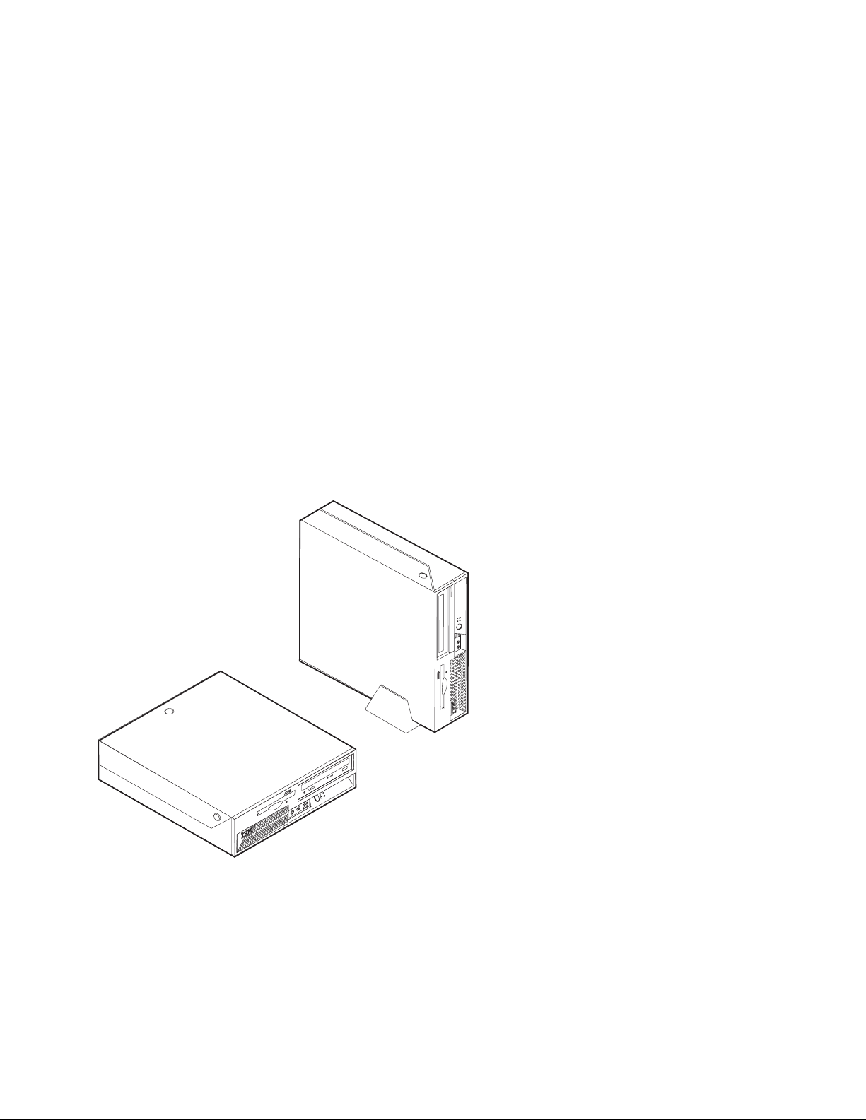
Overview
This guide contains instructions for replacing the following customer replacement
units (CRUs):
Power supply
System board
Microprocessor
Hard disk drive
Memory modules
Safety information
safety information” in the Quick Reference that was included with your computer. If
you no longer have this copy of the Quick Reference, you can obtain one online
from the IBM Web site at http://www.ibm.com/pc/support.
not open your computer or attempt any repair before reading the “Important
Additional information resources
you have Internet access, the most up-to-date manuals for your computer are
available from the World Wide Web. To access this information, point your browser
to: http://www.ibm.com/pc/support
Type your machine type and model number in the Quick path field, and click Go.
Tools required
replace some CRUs in your computer, you might need a flat-blade or Phillips
screwdriver. Additional tools might be needed for certain CRUs.
Handling static-sensitive devices
Static electricity, although harmless to you, can seriously damage computer
components and CRUs.
When you are replacing a CRU, do not open the static-protective package
containing the new CRU until the defective CRU has been removed from the
computer and you are ready to install the new CRU.
When you handle CRUs and other computer components, take these precautions to
avoid static-electricity damage:
Limit your movement. Movement can cause static-electricity to build up around
you.
Always handle CRUs and other computer components carefully. Handle
adapters, memory modules, system boards, and microprocessors by the edges.
Never touch any exposed circuitry.
Prevent others from touching the CRUs and other computer components.
Copyright IBM Corp. 2004
v
Page 8

v
v Do
vi
v
Before you replace a new CRU, touch the static-protective package containing
the CRU to a metal expansion-slot cover or other unpainted metal surface on the
computer for at least two seconds. This reduces static electricity in the package
and your body.
When possible, remove the new CRU from the static-protective packaging, and
install it directly in the computer without setting the CRU down. When this is
not possible, place the static-protective package that the CRU came in on a
smooth, level surface and place the CRU on it.
not place the CRU on the computer cover or other metal surface.
Hardware Removal and Replacement Guide
Page 9
Do
no
To
1.
2.
3.
4.
5. If a
6.
©
Replacing customer replaceable units (CRUs)
Attention
not open your computer or attempt any repair before reading the “Safety
notices” in the Quick Reference that was included with your computer. If you
longer have this copy of the Quick Reference, you can obtain one online
from the IBM Web site at http://www.ibm.com/pc/support.
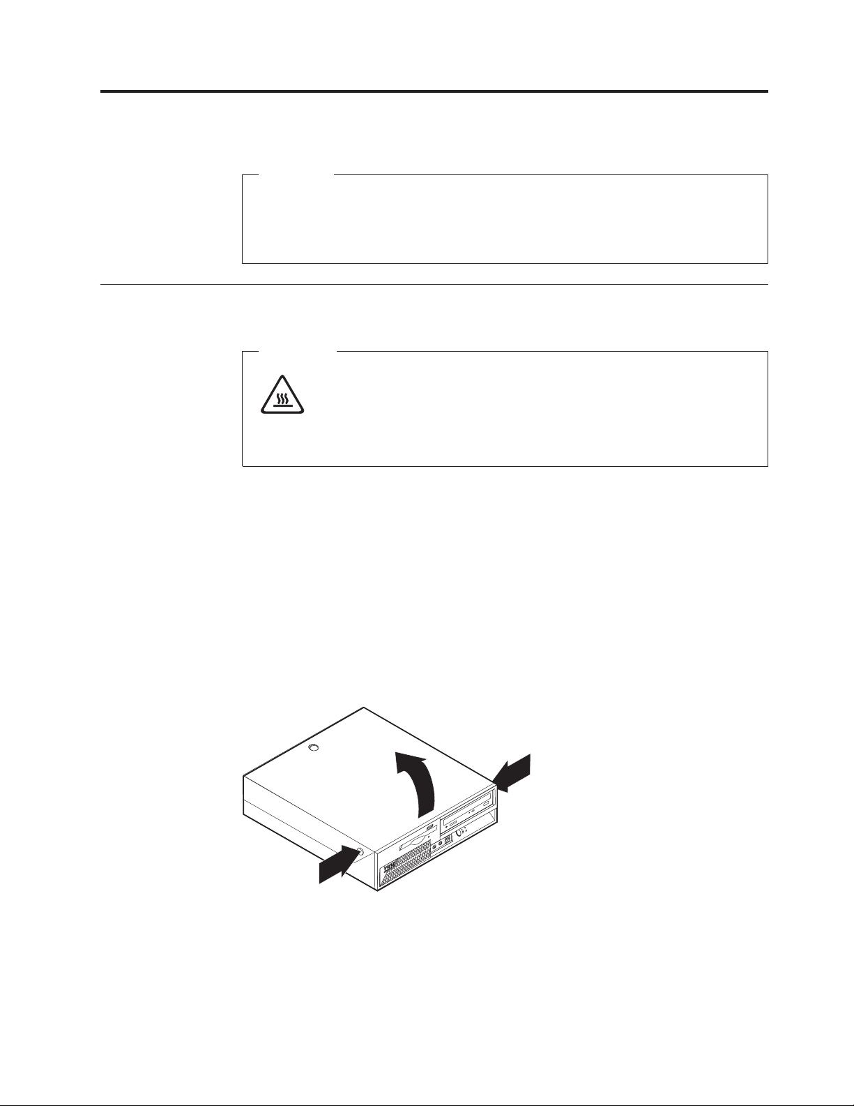
Opening the cover
Important
Turn off the computer and wait 3 to 5 minutes to let the computer cool
before opening the cover.
open the cover:
Remove any media (diskettes, CDs, or tapes) from the drives, shut down your
operating system, and turn off all attached devices.
Unplug all power cords from electrical outlets.
Disconnect all cables attached to the computer. This includes power cords,
input/output (I/O) cables, and any other cables that are connected to the
computer.
Remove the floor stand, if attached.
cover lock is installed, unlock the cover.
Press inward on the two buttons and pivot the top cover upward as illustrated.
Copyright IBM Corp. 2004
1
Page 10
2
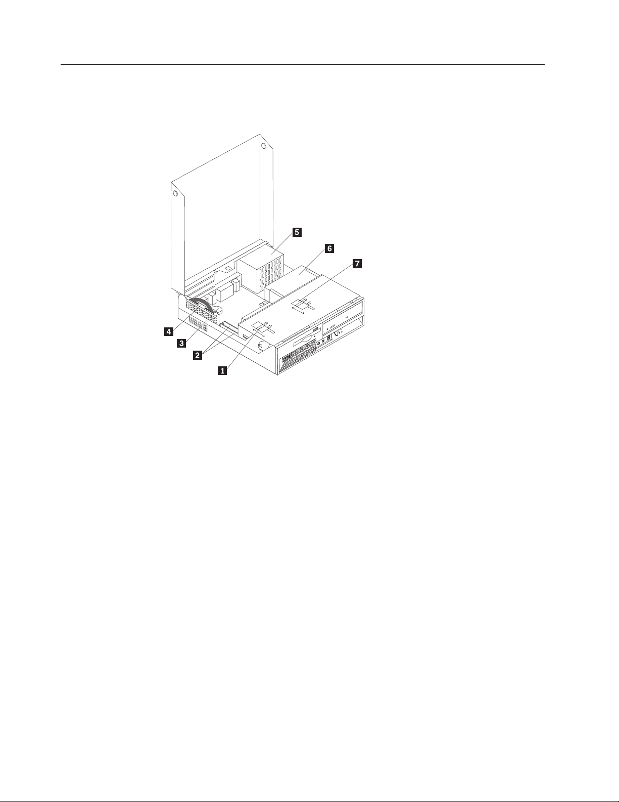
Locating components
The following illustration will help you locate the various components in your
computer.
1
2
3
4
Diskette drive lock
Memory modules
Battery
PCI riser
5 Power supply assembly
6 CD or DVD drive (hard disk drive is
under the CD drive)
7 CD or DVD drive lock
Hardware Removal and Replacement Guide
Page 11

Do
no
To
1.
Identifying parts on the system board
The system board (sometimes called the planar or motherboard) is the main circuit
board in your computer. It provides basic computer functions and supports a
variety of devices.
The following illustration shows the locations of parts on the system board.
1 Fan connectors (2)
2 Memory connectors (2)
3 SATA IDE hard disk drive
8 Diskette drive connector
9 Power button and front LED assembly
10 Power supply connector
connectors (2)
4 Riser connector
5 CMOS Battery
6 Clear CMOS/BIOS recovery
11 PATA Primary IDE connector (hard disk
12 Power supply connector
13 Microprocessor
jumper
7 Internal speaker connector
Removing and replacing the power supply
Attention
not open your computer or attempt any repair before reading the “Safety
notices” in the Quick Reference that was included with your computer. If you
longer have this copy of the Quick Reference, you can obtain one online
from the IBM Web site at http://www.ibm.com/pc/support.
remove and replace the power supply, do the following:
Open the cover. Go to “Opening the cover” on page 1.
connector
drive and CD-ROM drive)
Replacing customer replaceable units (CRUs)
3
Page 12

3.
4.
5.
6.
4
2.
Pivot the drive bay assembly upward to gain access to the cable connections.
Locate the power supply. See “Locating components” on page 2.
Note: Note the routing of the power supply cables. It is important to route
the cables the same way when installing a new power supply assembly.
Disconnect the power cables from the hard disk drive and the CD-ROM drive.
Disconnect the power cables P1 1and P2 2 from the system board.
Disconnect the wire from the internal speaker connector on the system board.
See “Identifying parts on the system board” on page 3.
Hardware Removal and Replacement Guide
Page 13

8.
7.
Remove the screws at the rear of the chassis that secure the power supply.
Slide the power supply forward and remove from the computer.
Replacing customer replaceable units (CRUs)
5
Page 14

6
9.
Install the new power supply into the chassis so that the screw holes in the
power supply align with those in the chassis.
Note: Use only the screws provided by IBM.
10.
Install and tighten the four screws at the rear of the chassis that secure the
power supply.
11.
Reconnect the speaker wire to the system board.
12.
Reconnect power supply connectors to the system board.
13.
Reconnect power supply connectors to the hard disk drive and CD-ROM
drive, as required.
14.
Correctly route all power supply cables to avoid interference with the drive
bay assembly, and fold the ribbon cables 1 and 2along the existing crease
lines.
Attention
Keep cables 1 through 3 clear of the hinges and sides of the
computer chassis.
15.
Close the cover and reconnect the external cables . Go to “Completing the
installation” on page 19.
Hardware Removal and Replacement Guide
Page 15

Do
no
To
1.
2.
3.
4.
Removing and replacing the system board assembly
Attention
not open your computer or attempt any repair before reading the “Safety
notices” in the Quick Reference that was included with your computer. If you
longer have this copy of the Quick Reference, you can obtain one online
from the IBM Web site at http://www.ibm.com/pc/support.
remove and replace the system board assembly, do the following:
Turn off the computer and allow the computer to cool for one hour.
Open the cover. Go to “Opening the cover” on page 1.
Pivot the drive bay assembly upward to gain access to the system board.
While holding the rear of the computer chassis down, pull upward on the
handle provided to remove the PCI riser and any adapters that are currently
Replacing customer replaceable units (CRUs)
7
Page 16

5.
be
6.
7.
8.
on
9.
8
installed.
Carefully note the location of all cable connections on the system board. It will
necessary to reconnect them properly after installing the new system board
assembly.
Note: Note the cable routing. It is important to route the cables the same way
when installing a new system board.
Disconnect the diskette drive cable from the system board by sliding the
plastic cable retainer upward to release the cable.
Disconnect all other cables connected to the system board. See “Identifying
parts on the system board” on page 3 to locate the cables.
Remove the power supply. Go to “Removing and replacing the power supply”
page 3.
Remove the six screws that secure the system board to the chassis.
Hardware Removal and Replacement Guide
Page 17

of
on
10.
Using the two blue handles provided, lift the system board assembly out of
the computer.
11.
Place the old system board next to the new system board on a clean, flat
surface.
12.
Remove the microprocessor from the old system board. Go to “Removing and
replacing the microprocessor” on page 10. Return here after removing the
microprocessor.
13.
Remove all memory modules from the old system board, and install them on
the new system board. Go to “Removing and replacing memory modules” on
page 15. Return here after installing the memory modules.
14.
Install the new system board into the computer chassis by aligning the two
tabs on the rear of the system board with the slots in the rear of the computer
chassis. Slide the system board to the rear of the computer until the front edge
the system board fits behind the flange in the front of the chassis and is
seated flush to the bottom of the chassis.
15.
Install the six screws to secure the system board to the chassis.
Note: Use only the screws provided by IBM.
16.
Reinstall the power supply. See “Removing and replacing the power supply”
page 3.
17.
Reconnect all cables that were disconnected from the system board. Make sure
all cables are routed correctly.
18.
Reinstall the PCI riser and any adapters that are currently installed.
19.
Lower the drive bay assembly into the original position.
20.
Close the cover and reconnect the external cables . Go to “Completing the
installation” on page 19.
Replacing customer replaceable units (CRUs)
9
Page 18

Do
no
To
1.
2.
3.
10
Removing and replacing the microprocessor
Attention
not open your computer or attempt any repair before reading the “Safety
notices” in the Quick Reference that was included with your computer. If you
longer have this copy of the Quick Reference, you can obtain one online
from the IBM Web site at http://www.ibm.com/pc/support.
Important
Shut down and turn off your computer for at least one hour before removing
the microprocessor to allow the thermal interface between the microprocessor
and the heat sink time to cool down.
When you receive a new microprocessor, you will also receive a new heat sink and
vacuum pen. You must use the new heat sink with the new microprocessor. If you
use the old heat sink with the new microprocessor, your computer might overheat
causing intermittent problems.
Important
Avoid handling the microprocessor with your hands, and avoid contact with
the microprocessor contacts. Use the vacuum pen provided to remove and
install the microprocessor. If you must touch the microprocessor, touch only
the sides.
remove the microprocessor, do the following:
Turn off the computer and allow it to cool for one hour.
Open the cover. Go to “Opening the cover” on page 1.
Pivot the drive bay assembly upward to gain access to the microprocessor.
Hardware Removal and Replacement Guide
Page 19

5.
v If
Do
If
6.
4.
Release the lever 1holding the microprocessor heat sink.
Remove the heat sink, and do one of the following:
you are replacing the microprocessor, place the old heat sink aside. You
must use the new heat sink shipped with the new microprocessor.
Note
not use the old heat sink with the a new microprocessor. If you use
the old heat sink with the new microprocessor, your computer might
overheat causing intermittent problems.
v
you are replacing the system board, carefully place the heat sink on its
side on a clean, flat surface so the thermal interface on the bottom of the
heat sink does not touch the surface and become contaminated.
Release the lever 3holding the microprocessor retainer 1, and pivot the
retainer to the open position.
*XXXXXXXXX*
Replacing customer replaceable units (CRUs)
11
Page 20

a.
b. Do
7. To
To
Do
If
a.
12
Notes:
Notice of the orientation of the notches 1 on the microprocessor . This is
important when reinstalling the microprocessor on the system board.
* XXXXXXXXX*
not drop anything on the socket while it is open. Keep all contacts as
clean as possible.
install the microprocessor, do one of the following:
Attention
avoid damaging the microprocessor pins, do not tilt the
microprocessor when installing it into the microprocessor socket.
Important
not touch the gold contacts on the bottom of the microprocessor. If
you must touch the microprocessor, touch only the sides.
v
you are installing a new microprocessor:
Remove the old microprocessor using the vacuum pen and place the
microprocessor aside.
Hardware Removal and Replacement Guide
Page 21

c.
d.
e.
f.
g.
If
a.
b.
Remove the new microprocessor from its static-protective package.
* XXXXXXXXX*
Hold the microprocessor 2 by its sides and loosen the black cover
3on the microprocessor, but do not remove the black cover.
Place the microprocessor on the static-protective package.
Use the vacuum pen 1 to pick up the new microprocessor, and
remove the black cover.
Place the black cover on the old microprocessor to protect the gold
contacts.
Install the new microprocessor by inserting it straight down into the
socket.
you are replacing the system board:
v
Use the vacuum pen 1 to pick up the microprocessor from the old
system board.
Replacing customer replaceable units (CRUs)
13
Page 22

8.
9. Do
v If
Do
If
a. A
b.
14
b.
Install the microprocessor by inserting it straight down into the socket of
the new system board.
Pivot the retaining plate 1 closed, and lock the lever 3 to secure the
microprocessor2 in place. Be sure to engage the retainer tab when locking
the microprocessor.
*XXXXXXXXX*
one of the following:
you have replaced the microprocessor, place the new heat sink on the
microprocessor, and lower the lever into the locked position.
Note
not use the old heat sink with the a new microprocessor. If you use
the old heat sink with the new microprocessor, your computer might
overheat causing intermittent problems.
v
you have replaced the system board:
black cover will cover the retaining plate protecting the contacts on
the new system board. Remove this black cover after you have locked
the microprocessor in place. Place this cover on the retaining plate of the
old system board.
Reinstall the original heat sink on the microprocessor, and lower the
lever into the locked position. Return to the system board procedure.
10.
Close the cover and reconnect the external cables . Go to “Completing the
installation” on page 19.
Hardware Removal and Replacement Guide
Page 23

Do
no
To
1.
2.
3.
Removing and replacing memory modules
Attention
not open your computer or attempt any repair before reading the “Safety
notices” in the Quick Reference that was included with your computer. If you
longer have this copy of the Quick Reference, you can obtain one online
from the IBM Web site at http://www.ibm.com/pc/support.
remove and replace the memory modules:
Open the cover. Go to “Opening the cover” on page 1.
Pivot the drive bay assembly upward to gain access to the system board.
While holding the rear of the computer chassis down, pull upward on the
handle provided to remove the PCI riser and any adapters that are currently
Replacing customer replaceable units (CRUs)
15
Page 24

4.
5.
6.
16
installed.
Locate the memory connectors. See “Locating components” on page 2.
Open the retaining clips, and lift the memory module out of its connector.
Insert the replacement memory module in the memory connector. Ensure the
notch on the replacement memory module 1aligns correctly with the
connector key 2 on the system board. Push the memory module straight
down into the connector until the retaining clips close.
Hardware Removal and Replacement Guide
Page 25

8.
9.
7.
Reinstall the PCI riser and adapters if they were removed.
Pivot the drive bay assembly back to the original position.
Close the cover and reconnect the external cables . Go to “Completing the
installation” on page 19.
Replacing customer replaceable units (CRUs)
17
Page 26

Do
no
1.
2.
3. If a CD
4.
5.
18
Removing and replacing a hard disk drive
Attention
not open your computer or attempt any repair before reading the “Safety
notices” in the Quick Reference that was included with your computer. If you
longer have this copy of the Quick Reference, you can obtain one online
from the IBM Web site at http://www.ibm.com/pc/support.
Open the cover. Go to “Opening the cover” on page 1.
Pivot the drive bay assembly upward to gain access to the cable connections.
drive is installed, to disconnect the signal cable from the drive to
access the hard disk drive cables.
Note: Blue straps are provided to help when disconnecting cables.
Disconnect the signal and power cables from the hard disk drive.
Pivot the hard disk drive to the rear, then pull the hard disk drive out of the
hard drive bay by pulling on the blue handle.
Hardware Removal and Replacement Guide
Page 27

Do
7.
8.
9.
To
1.
or
2.
6.
Remove the old hard disk drive from the blue bracket by flexing the bracket.
not touch the circuits 5 on the hard disk drive.
Insert the new hard disk drive into the blue bracket aligning the pins 1
through 4on the bracket with the holes in the hard disk drive.
Insert the hard disk drive into hard disk bay with the circuits facing up and
snap it into position.
Connect a power connector to the drive.
10.
Reconnect the CD drive cable.
11.
Lower the drive bay assembly into the original position.
12.
Close the cover and reconnect the external cables . Go to “Completing the
installation.”
Completing the installation
After replacing the CRUs, you need to close the cover and reconnect cables,
including telephone lines and power cords. Also, depending on the CRU that was
replaced, you might need to confirm the updated information in the IBM Setup
Utility program. See ″Starting the IBM Set Utility″ in your Quick Reference.
complete the CRU installation:
Ensure that all components have been reassembled correctly and that no tools
loose screws are left inside your computer. See “Locating components” on
page 2 for the location of various components.
Correctly route all power supply cables to avoid interference with the drive bay
assembly, and fold the ribbon cables 1 and 2along the existing crease lines.
Replacing customer replaceable units (CRUs)
19
Page 28

3.
4.
5. If a
6. If
20
Attention
Keep cables 1 through 3 clear of the hinges and sides of the computer
chassis.
Make sure that the drive locks on the drive bay assembly are both in the
locked position. Otherwise, you cannot close the cover.
Close the cover.
cover lock is installed, lock the cover.
your computer is being placed in the vertical position, attach the floor stand.
Attention: To prevent overheating and possible component damage, always
attach the floor stand when placing the computer in the vertical position.
Hardware Removal and Replacement Guide
Page 29

a
8. If
9. To
To
1.
in
2.
7.
Reconnect the external cables. Plug the power cord into the computer then into
properly grounded power receptacle.
1 Power cord connector
2 Cable lock latch
3 Rope clip (U-bolt) holes
4 PCI and PCI express adapter slots 12 USB connectors (4)
5 Serial connectors (2)
6 Ethernet connector
7 USB connectors (2)
8 VGA monitor connector
you are replacing the system board, you must update (flash) the BIOS, see
“Updating (flashing) BIOS from a diskette.”
update your configuration, see ″Starting the IMB Setup Utility″ in the Quick
Reference that was included with your computer.
Updating (flashing) BIOS from a diskette
Important
Start the IBM Setup Utility program to view your system information. See
“Starting the IBM Setup Utility” in your Quick Reference. If the serial number
and the machine type/model listed on the Main menu do not match what is
printed on the label of your computer, you must update (flash) the BIOS to
change the serial number and the machine type/model.
9
Parallel connector
10 Audio line-in connector
11 Audio line-out connector
13 PS/2 keyboard connector
14 PS/2 mouse connector
15 LEDs
update (flash) the BIOS from a diskette, do the following:
Insert a system program update (flash) diskette into the diskette drive (drive A)
your computer. System program updates are available at
http://www.ibm.com/pc/support on the World Wide Web.
Turn on the computer. If it is on already, you must turn it off and back on
again. The update begins.
Replacing customer replaceable units (CRUs)
21
Page 30

4.
5.
6.
7.
8.
22
3.
When you are prompted to select a language, press the number on your
keyboard which corresponds to the language then press Enter.
When prompted to change the serial number, press Y.
Type in the seven character serial number of your computer then press Enter.
When prompted to change the machine type/model, press Y.
Type in the seven character machine type/model of your computer then press
Enter.
Follow the instructions on the screen to complete the update.
Hardware Removal and Replacement Guide
Page 31

Page 32

Part Number: 19R0821
Printed in USA
(1P) P/N: 19R0821
 Loading...