

Page 1
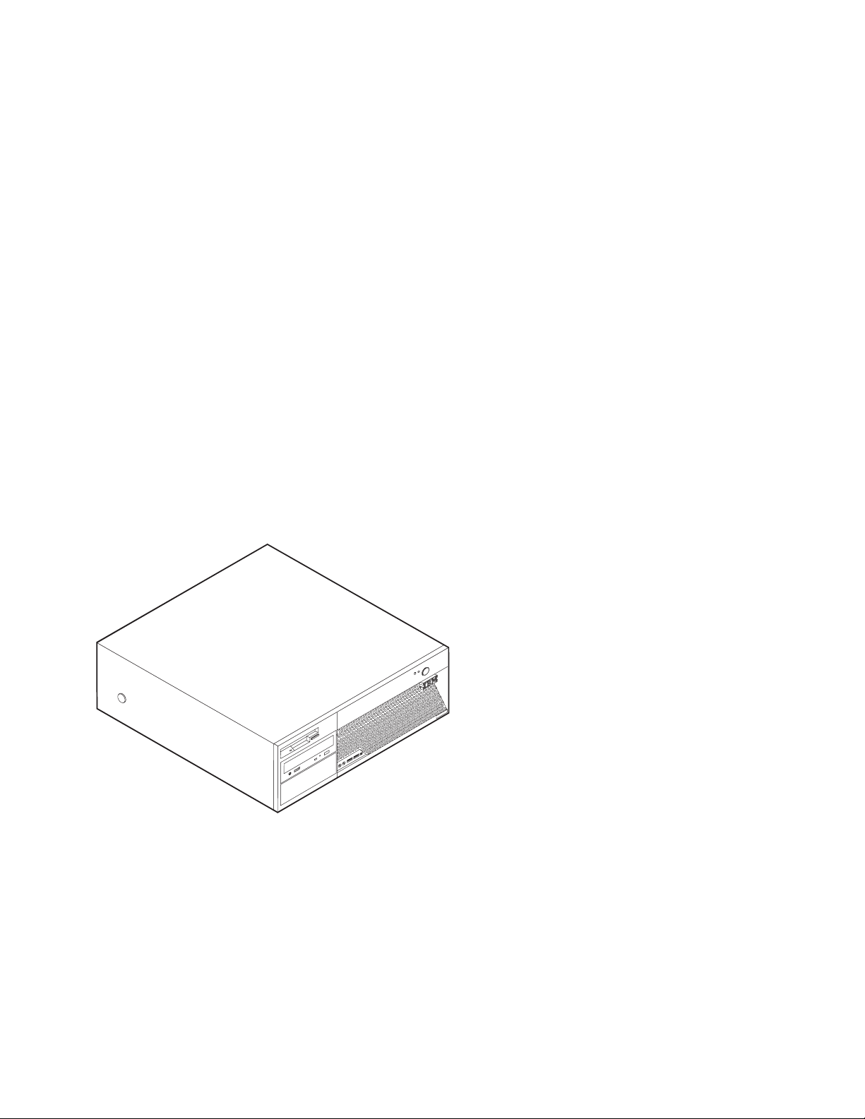
ThinkCentre
™
Hardw are Remov al an d Replacement
Gui de
Ty pe s 8141, 8142, 8145
Ty pe s 8420, 8421, 8426
ThinkCentre
Page 2

Page 3

ThinkCentre
™
Hardw are Remov al an d Replacement
Gui de
Ty pe s 8141, 8142, 8145
Ty pe s 8420, 8421, 8426
Page 4

©
US
First Edition (May 2004)
Copyright International Business Machines Corporation 2004. All rights reserved.
Government Users Restricted Rights – Use, duplication or disclosure restricted by GSA ADP Schedule Contract
with IBM Corp.
Page 5

©
Contents
Overview . . . . . . . . . . . . . .v
Information resources . . . . . . . . . . .v
Tools required . . . . . . . . . . . . . .v
Handling static-sensitive devices . . . . . . .v
Replacing customer replaceable units
(CRUs) . . . . . . . . . . . . . . .1
Removing the cover . . . . . . . . . . . .1
Removing and replacing the power supply . . . .2
Removing and replacing the system board . . . .4
Removing and replacing the microprocessor . . . .7
Removing and replacing the hard disk drive . . .12
Connecting a serial ATA hard disk drive . . . .13
Connecting a parallel ATA hard disk drive . . .13
Removing and replacing memory . . . . . . .13
Removing and replacing a PCI adapter . . . . .15
Completing the CRU replacement . . . . . . .16
Copyright IBM Corp. 2004
iii
Page 6

iv
Hardware Removal and Replacement Guide
Page 7

v
v
v
v
v
If
to
To
to
v
v
v
©
Overview
This manual contains instructions for removing and replacing the following
customer replacement units (CRUs):
Power supply
System board
Microprocessor
Memory
Hard disk drive
Information resources
The Quick Reference that comes with your computer provides information for
installing your computer and starting the operating system. It also includes basic
troubleshooting information, software recovery procedures, help and service
information, and warranty information.
Access IBM, on your desktop, provides a link to more information about your
computer.
you have Internet access, the most up-to-date manuals for your computer are
available from the World Wide Web. To access this information, point your browser
http://www.ibm.com/pc/support
Type your machine type and model number in the Quick Path field, and click Go.
Tools required
install some options in your computer, you might need a flat-blade or Phillips
screwdriver. Additional tools might be needed for certain options. See the
instructions that come with the option.
Handling static-sensitive devices
Static electricity, although harmless to you, can seriously damage computer
components and options.
When you add an option, do not open the static-protective package containing the
option until you are instructed to do so.
Copyright IBM Corp. 2004
When you handle options and other computer components, take these precautions
avoid static electricity damage:
Limit your movement. Movement can cause static electricity to build up around
you.
Always handle components carefully. Handle adapters and memory modules by
the edges. Never touch any exposed circuitry.
Prevent others from touching components.
v
Page 8

v
on
v Do
vi
v
When you install a new option, touch the static-protective package containing
the option to a metal expansion-slot cover or other unpainted metal surface on
the computer for at least two seconds. This reduces static electricity in the
package and your body.
When possible, remove the option and install it directly in the computer without
setting the option down. When this is not possible, place the static-protective
package that the option came in on a smooth, level surface and place the option
it.
not place the option on the computer cover or other metal surface.
Hardware Removal and Replacement Guide
Page 9
Do
To
1.
2.
3.
©
Replacing customer replaceable units (CRUs)
Attention
not open your computer or attempt any repair before reading the
“Important safety information” in the Quick Reference that was included with
your computer. If you no longer have this copy of the Quick Reference, you
can obtain one online from the IBM Web site at
http://www.ibm.com/pc/support.
Removing the cover
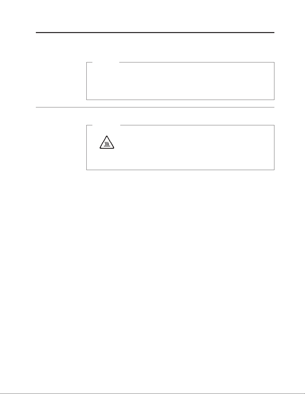
Important
Turn off your computer and wait 3 to 5 minutes to let the computer cool
before removing the cover.
remove the cover:
Shut down your operating system, remove any media (diskettes, CDs, or tapes)
from the drives, and turn off all attached devices and the computer.
Unplug all power cords from electrical outlets.
Disconnect all cables attached to the computer. This includes power cords,
input/output (I/O) cables, and any other cables that are connected to the
computer.
Copyright IBM Corp. 2004
1
Page 10

Do
1.
2
4.
Press the buttons on the sides of the computer and pivot the rear end of the
cover up toward the front of the computer.
tre
n
e
C
k
in
h
T
Removing and replacing the power supply
Attention
not open your computer or attempt any repair before reading the
“Important safety information” in the Quick Reference that was included with
your computer. If you no longer have this copy of the Quick Reference, you
can obtain one online from the IBM Web site at
http://www.ibm.com/pc/support.
This section provides instructions on how to remove and replace the power supply.
Remove the cover. See “Removing the cover” on page 1.
Hardware Removal and Replacement Guide
Page 11

3.
4.
2.
Remove the four screws at the rear of the chassis.
Rotate the drive bay assembly upward to gain access to the system board.
*XXXXXXXXX*
*XXXXXXXXX*
Disconnect all power supply cables from the drives and the system board.
Remove the cables from the cable clips and ties. See Figure 1 on page 5.
Note: Take note of the locations of the power supply cables.
Replacing customer replaceable units (CRUs)
3
Page 12

6.
in
7.
8.
9. To
Do
1.
2.
4
5.
Remove the power supply assembly from the computer.
Install the new power supply assembly into the chassis so that the screw holes
the power supply assembly align with those in the chassis.
Note: Use only the screws provided by IBM.
Install and tighten the four power supply assembly screws into the rear of the
chassis.
Route the cables through the cable clips and ties. Reconnect all the power
supply cables to the drives and the system board.
complete the installation, go to “Completing the CRU replacement” on page
16.
Removing and replacing the system board
Attention
not open your computer or attempt any repair before reading the
“Important safety information” in the Quick Reference that was included with
your computer. If you no longer have this copy of the Quick Reference, you
can obtain one online from the IBM Web site at
http://www.ibm.com/pc/support.
*XXXXXXXXX*
*XXXXXXXXX*
This section provides instructions on how to remove and replace the system board.
Remove the cover. See “Removing the cover” on page 1.
Remove any PCI adapters. See “Removing and replacing a PCI adapter” on
page 15.
Hardware Removal and Replacement Guide
Page 13

4.
3.
Carefully take note of the location of all cable connections on the system
board. It will be necessary to reconnect them properly when installing a new
system board.
Disconnect all cables connected to the system board.
Figure 1. System board
1 12v power connector
2 Diskette drive connector
3 Speaker connector
4 DIMM connector 4
5 DIMM connector 3
6 DIMM connector 2
7 DIMM connector 1
8 Clear CMOS/Recovery jumper
9 Front panel connector
10Parallel ATA IDE connector
11SATA 4 connector
12SATA 3 connector
13SATA 2 connector
14SATA 1 connector
15Cover presence switch connector
16Power supply connector
17PCI Express (x16) graphics slot
18PCI Express (x1) slot
19PCI slot 2
20PCI slot 1
21Battery
22Microprocessor
23Microprocessor fan connector
24Microprocessor heat sink
Replacing customer replaceable units (CRUs)
5
Page 14

6.
7.
on
8.
7. 9.
6
5.
Remove the seven screws that attach the system board to the chassis and slide
the system board toward the drive bay assembly. Carefully lift out the system
board.
*XXXXXXXXX*
*XXXXXXXXX*
Take note of the location of the DIMMs and remove them from the system
board. See “Removing and replacing memory” on page 13.
Install the DIMMs on the new system board in the same location as they were
the system board being replaced.
Remove the microprocessor from the failing system board and install it on the
new system board. See “Removing and replacing the microprocessor” on page
Install the new system board by aligning the slots in the metal plate on the
bottom of the system board with the tabs on the chassis then slide the system
board toward the rear of the computer.
*XXXXXXXXX*
*XXXXXXXXX*
Hardware Removal and Replacement Guide
Page 15

If
To
Do
1.
Important
the metal plate is not aligned correctly when you install the screws,
you might damage the system board.
10.
Install the screws that secure the system board to the chassis.
11.
Reconnect all cables that were disconnected from the system board. See
Figure 1 on page 5.
12.
Replace any PCI adapters that were removed. See “Removing and replacing a
PCI adapter” on page 15.
13.
complete the installation, go to “Completing the CRU replacement” on
page 16.
Removing and replacing the microprocessor
Attention
not open your computer or attempt any repair before reading the
“Important safety information” in the Quick Reference that was included with
your computer. If you no longer have this copy of the Quick Reference, you
can obtain one online from the IBM Web site at
http://www.ibm.com/pc/support.
Important
Shut down and turn off your computer for at least one hour before removing
the microprocessor to allow the thermal interface between the microprocessor
and the heat sink time to cool down.
When you receive a new microprocessor, you will also receive a new heat sink and
vacuum pen. You must also replace the heat sink when replacing the
microprocessor. If you use the old heat sink with the new microprocessor, your
computer might over heat and periodically shut down.
This section provides instructions on how to remove and replace the
microprocessor.
Remove the cover. See “Removing the cover” on page 1.
Replacing customer replaceable units (CRUs)
7
Page 16

3.
8
2.
Rotate the drive bay assembly upward to gain access to the system board.
*XXXXXXXXX*
*XXXXXXXXX*
Remove the heat sink 2 from the system board by rotating the lever 1
securing the heat sink until it is fully in the up position. Carefully lift the heat
sink off of the system board.
Note: If you are only replacing the system board, place the heat sink on its
side on a clean, flat surface so the thermal interface on the bottom of the heat
sink does not touch the surface.
Hardware Removal and Replacement Guide
Page 17

5.
Do
a.
b. Do
6.
4.
Release the lever 2 securing the microprocessor 1 then rotate the
microprocessor retainer 3 until it is fully in the up position.
Remove the microprocessor from the system board socket using the vacuum
pen1.
Important
not touch the gold contacts on the bottom of the microprocessor. If
you must touch the microprocessor, touch only the sides.
Notes:
Take notice of the orientation of the notches on the microprocessor. This is
important when reinstalling the microprocessor on the system board.
not drop anything on the socket while it is open. Keep all contacts as
clean as possible.
Make sure that the lever on the microprocessor retainer is fully in the up
position.
Replacing customer replaceable units (CRUs)
9
Page 18

8.
To
9.
10
7.
When installing a new microprocessor2, loosen the black cover 3that
protects the gold contacts on the microprocessor, but do not remove it. Use the
vacuum pen 1 to pick up the new microprocessor then completely remove
the black cover.
* XXXXXXXXX*
Position the microprocessor so that the notches 1 on the microprocessor are
aligned with the tabs in the microprocessor socket.
Important
avoid damaging the microprocessor contacts, do not tilt the
microprocessor when installing it into the socket.
* XXXXXXXXX*
Use the vacuum pen to lower the microprocessor straight down into the
system board socket.
Hardware Removal and Replacement Guide
Page 19

If
10.
Lower the microprocessor retainer 3 and then lower the lever 2 to secure
the retainer. Make sure the lever is securely locked into position.
Note: If you are replacing the system board, a piece of black plastic will cover
the microprocessor retainer. When you lock the microprocessor in position,
remove the cover.
11.
Place the new heat sink2into position and lower the lever 1 to secure the
heat sink.
Note: If you are only replacing a system board, install and secure the original
heat sink on the microprocessor.
12.
you are replacing the system board, continue at Removing and replacing the
system board at step 9 on page 6. If you are replacing a failing microprocessor,
continue at step 13 on page 12.
Replacing customer replaceable units (CRUs)
11
Page 20

To
Do
1.
2.
3.
4.
12
13.
complete the installation, go to “Completing the CRU replacement” on
page 16.
Removing and replacing the hard disk drive
Attention
not open your computer or attempt any repair before reading the
“Important safety information” in the Quick Reference that was included with
your computer. If you no longer have this copy of the Quick Reference, you
can obtain one online from the IBM Web site at
http://www.ibm.com/pc/support.
This section provides instructions on how to remove and replace the hard disk
drive.
Remove the cover. See “Removing the cover” on page 1.
Rotate the drive bay assembly upward to gain access to the system board.
*XXXXXXXXX*
*XXXXXXXXX*
Disconnect the signal and power cables from the rear of the hard disk drive.
Lift the hard disk drive and bracket up to remove it from the drive bay.
*XXXXXXXXX*
*XXXXXXXXX*
Hardware Removal and Replacement Guide
Page 21

6.
7.
to
8.
9.
A
1.
2.
5. 3.
4.
5. To
1.
2.
3.
4. To
Do
1.
5.
Note the orientation of the hard disk drive in the plastic bracket.
Remove the drive by flexing the plastic enough to slide the drive out.
Install the hard disk drive into the plastic bracket by flexing the plastic enough
slide the drive in.
Install the hard disk drive and bracket into the bay until it snaps into position.
Depending on the type of drive you are installing, go to “Connecting a serial
ATA hard disk drive” or “Connecting a parallel ATA hard disk drive.”
Connecting a serial ATA hard disk drive
serial hard disk drive can be connected to any available SATA connector.
Locate the signal cable that comes with the new drive.
Locate an available SATA connector on the system board. See Figure 1 on page
Connect one end of the signal cable to the drive and the other to an available
SATA connector on the system board.
Connect a power connector to the drive.
complete the installation, go to “Completing the CRU replacement” on page
16.
Connecting a parallel ATA hard disk drive
Locate the PATA IDE connector on the system board and the three-connector
signal cable.
Connect one end of the signal cable to the drive and the other to the PATA IDE
connector on the system board. See Figure 1 on page 5.
Connect a power connector to the drive.
complete the installation, go to “Completing the CRU replacement” on page
16.
Removing and replacing memory
Attention
not open your computer or attempt any repair before reading the
“Important safety information” in the Quick Reference that was included with
your computer. If you no longer have this copy of the Quick Reference, you
can obtain one online from the IBM Web site at
http://www.ibm.com/pc/support.
This section provides instructions on how to remove and replace memory.
Remove the cover. See “Removing the cover” on page 1.
Replacing customer replaceable units (CRUs)
13
Page 22

3.
4.
5.
on
6. To
14
2.
Rotate the drive bay assembly upward to gain access to the system board.
*XXXXXXXXX*
*XXXXXXXXX*
Remove any parts that might prevent access to the DIMM slots.
Remove the DIMM being replaced by opening the retaining clips as shown.
Make sure that the DIMM notch 1 aligns correctly with the connector key2
the system board. Push or insert the DIMM straight down into the
connector until the retaining clips close.
complete the installation, go to “Completing the CRU replacement” on page
16.
Hardware Removal and Replacement Guide
Page 23

Do
1.
2.
3.
4.
Removing and replacing a PCI adapter
Attention
not open your computer or attempt any repair before reading the
“Important safety information” in the Quick Reference that was included with
your computer. If you no longer have this copy of the Quick Reference, you
can obtain one online from the IBM Web site at
http://www.ibm.com/pc/support.
This section provides instructions on how to remove and replace a PCI adapter.
Remove the cover. See “Removing the cover” on page 1.
Rotate the drive bay assembly upward to gain access to the system board.
*XXXXXXXXX*
*XXXXXXXXX*
Open the adapter latch and remove the failing adapter.
*XXXXXXXXX*
*XXXXXXXXX*
Remove the new adapter from its static-protective package.
Replacing customer replaceable units (CRUs)
15
Page 24

6.
7. To
1.
or
2.
3.
4.
16
5.
Install the new adapter into the appropriate slot on the system and close the
adapter latch.
*XXXXXXXXX*
*XXXXXXXXX*
Rotate the drive bay assembly back to the normal position.
complete the installation, go to “Completing the CRU replacement.”
Completing the CRU replacement
After working with CRUs, you need to install any removed parts, replace the
cover, and reconnect any cables, including telephone lines and power cords.
Ensure that all components have been reassembled correctly and that no tools
loose screws are left inside your computer.
Lower the drive bay assembly.
Clear any cables that might impede the replacement of the cover.
Position the cover over the chassis and pivot it down over the computer until it
snaps into place.
Hardware Removal and Replacement Guide
Page 25

6. If a
5.
Reconnect the external cables and power cords to the computer.
1PCI slots
2PCI Express (x1) slot
3PCI Express (x16) graphics slot
4Ethernet connector
5USB connectors
6Mouse connector
7Parallel connector
8Serial connector (some models)
cover lock is installed, lock the cover.
9 Diagnostic LEDs
10Power connector
11Audio line out connector
12Audio line in connector
13VGA monitor connector
14Serial connector
15Keyboard connector
16USB connectors
Replacing customer replaceable units (CRUs)
17
Page 26

18
Hardware Removal and Replacement Guide
Page 27

Page 28

Part Number: 19R0805
Printed in USA
(1P) P/N: 19R0805
 Loading...