

Hyundai h lcd1502 schematic
SERVICE MANUAL
8T83 CHASSIS
HYUNDAI
LCD-1502
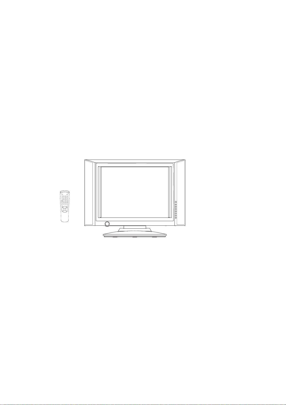
15.1INCH LCD TV
MANUAL
Design and specifications are subject to change without prior notice.
( ONLY REFERRENCE)
PR.FROLOV
ENGINEER BY: CHECKED BY: PPROVED BY:
_____
_____
_____

Contents
Note
----------------------------------------------------------------Technical specification-------------------------------------------Chassis Block Diagram-------------------------------------------IC Block Diagram --------------------------------------------------Transistor mark ---------------------------------------------------PCB Top/Bottom layer --------------------------------------------Service Adjustments ----------------------------------------------Control Location ---------------------------------------------------Input and Output Terminals--------------------------------------Operation Instructions
--------------------------------------------Cabinet parts List -------------------------------------------------Circuit Diagram-----------------------------------------------------
2
3-4
5
6-12
13
14-18
19-20
21
22
23-30
31
32
-2-
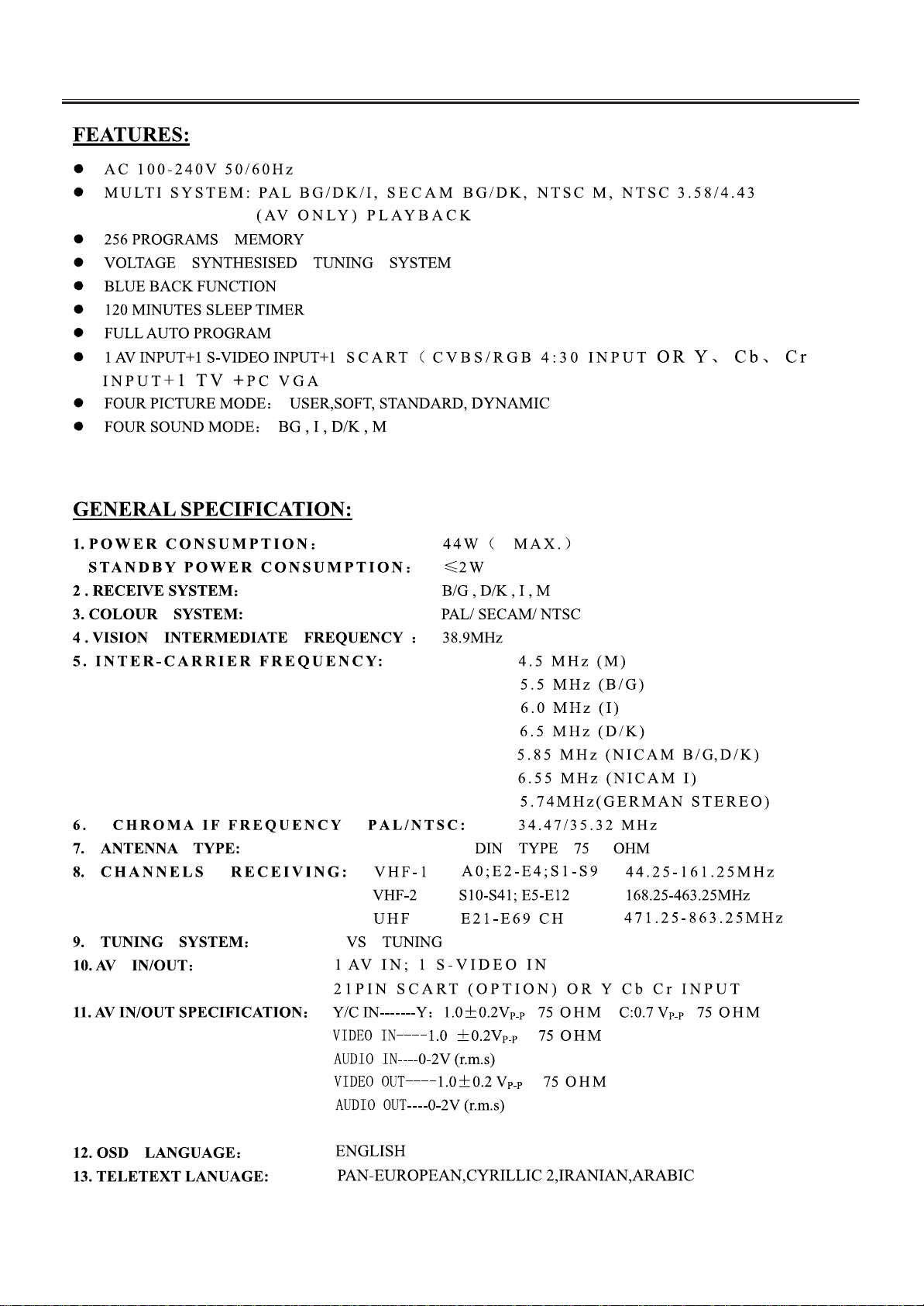
TECHNICAL SPECIFICATION
-3-
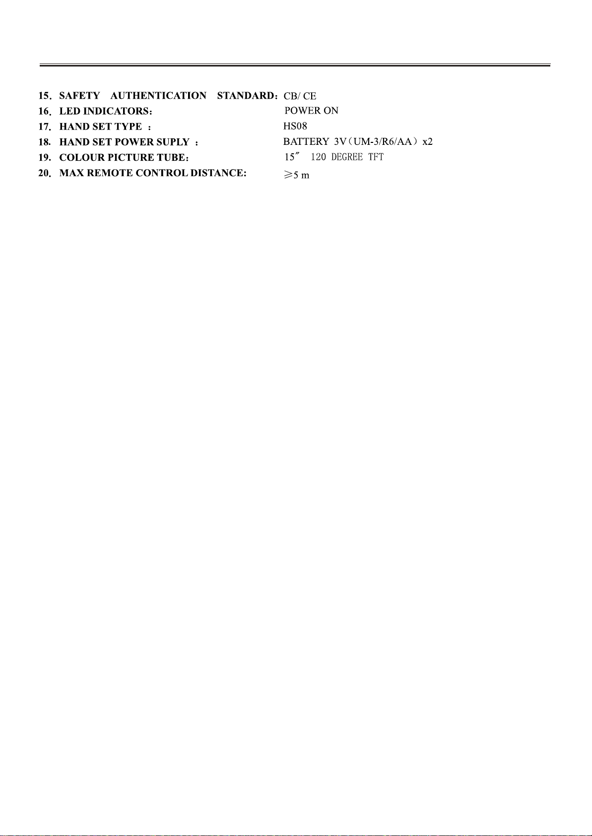
TECHNICAL SPECIFICATION
-4-
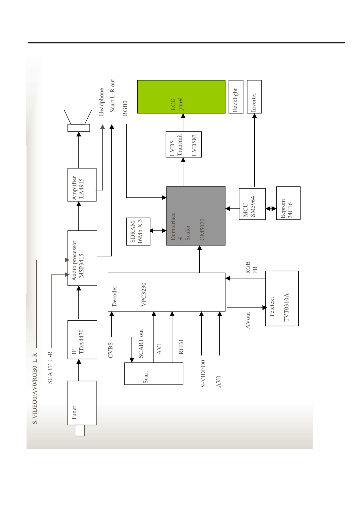
Chassis Block Diagram
-5-
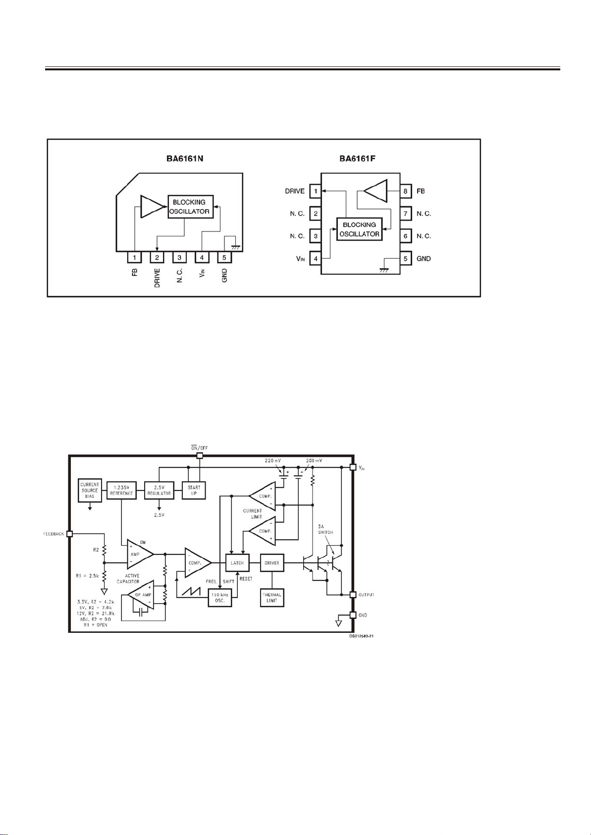
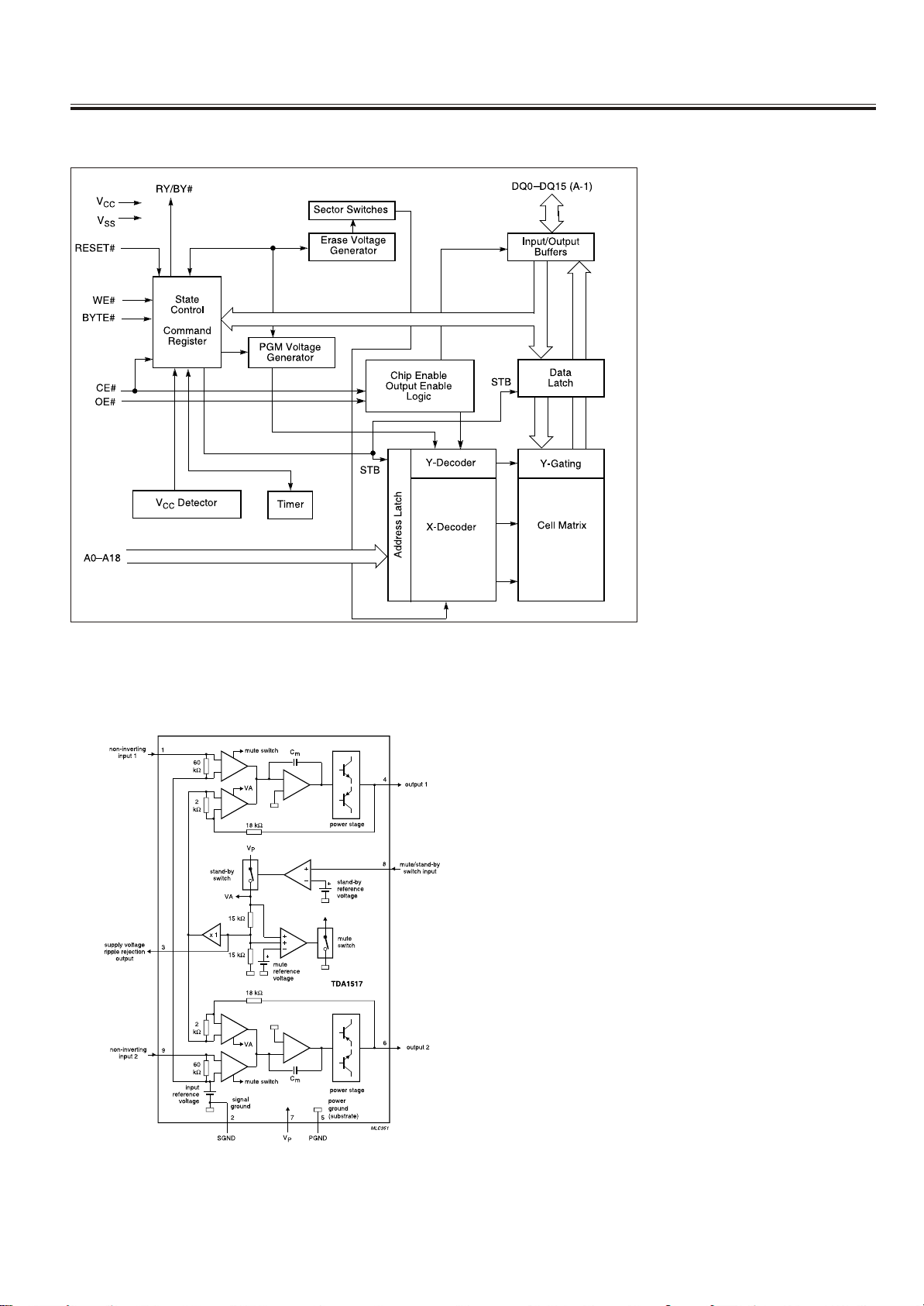
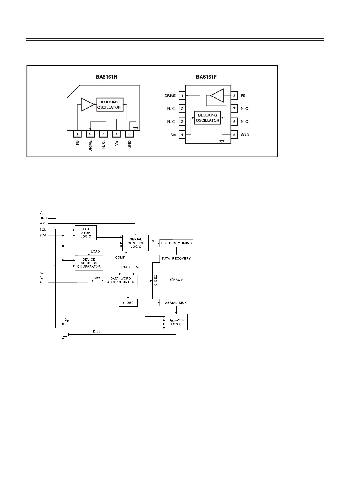
IC Block Diagram
IC 900 ( 8-BIT MCU) BA6161A
IC 905 LM2596S
-6-
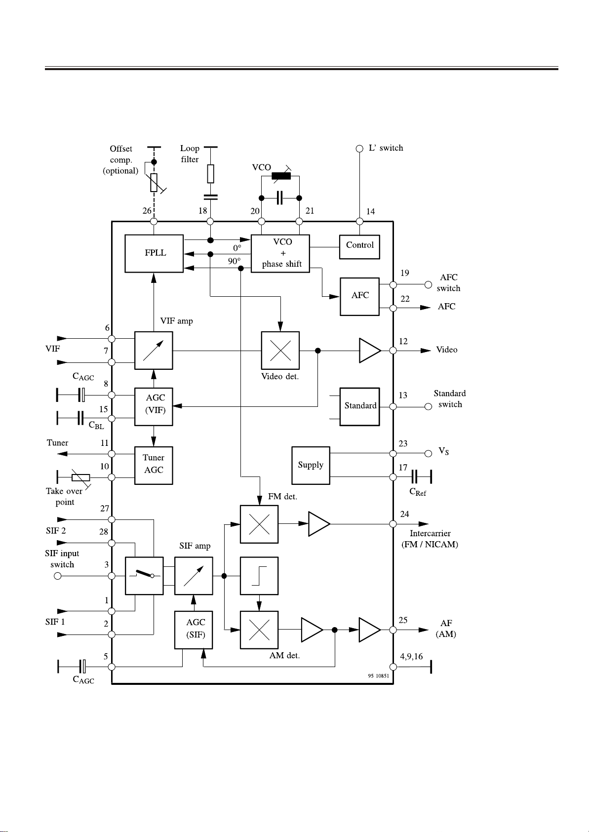
IC Block Diagram
IC2 TDA4470
IC602(POWER ) STR-G6653
-7-
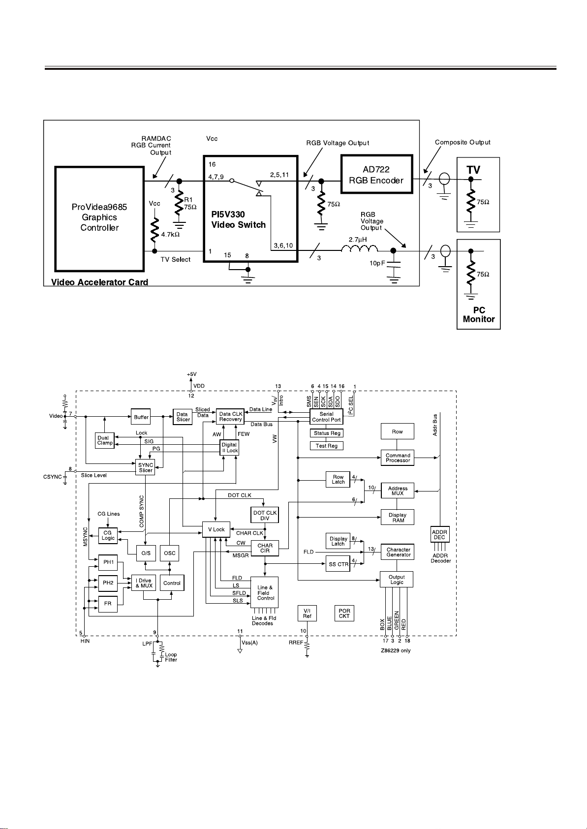
IC Block Diagram
U302 U103 (VIDEO QUAD 2-CHAN NEL MUX/DEMUX) PI5V330Q
U307( NTSC LINE 21 CCD DECODER) Z8622912PSC
-8-
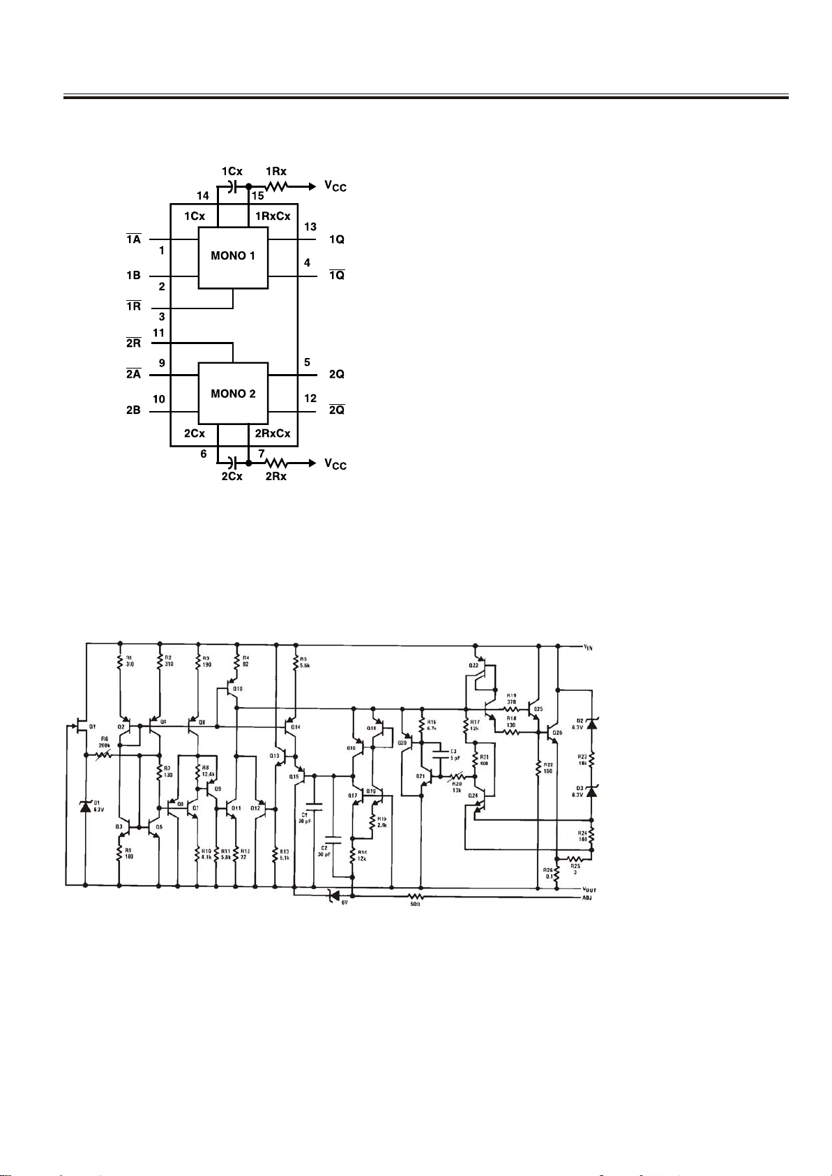
IC Block Diagram
U311 U313 U412 (DUAL RETRIGGERABLE MONSTABLE MULTIVIBRATOR ) 74HC123D
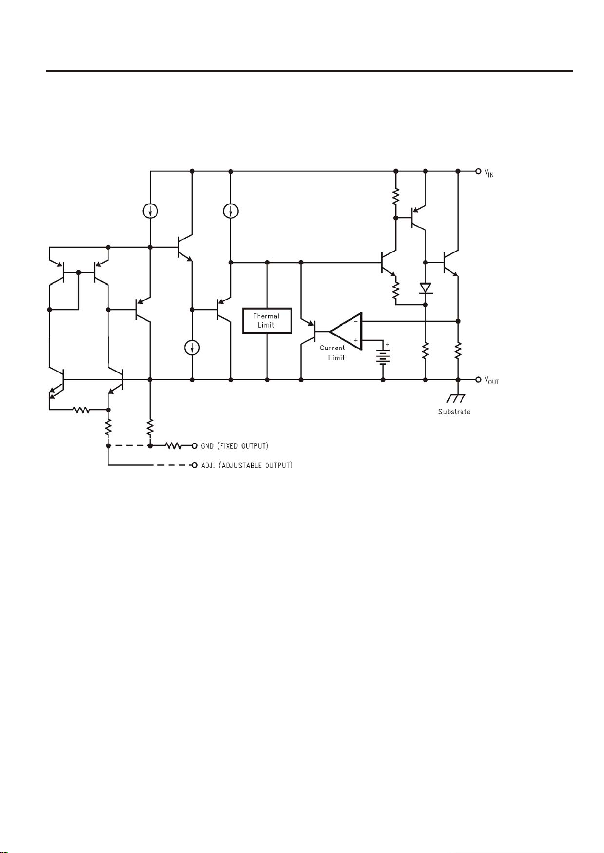
U304 (1.2V TO 37V VOLTAGE REGULATOR) LM317
-9-
IC Block Diagram
U106 (8M BIT CMOS 3 V BOOT FLASH MEMORY) AM29LV800BT-90EC
U309 (2 X 6W STEREO POW ER AMPLIFIER) TDA1517P
-10-
IC Block Diagram
U305 (Teletext Decoders) BA6161NU305 (Teletext Decoders) BA6161N
U107 (SWITCHING REGULATOR F OR ELECTRONIC TUNING) AT24C16N-10SA-2.7C
-11-
IC Block Diagram
U112 U113 U115 U116 (800mA LOW DROPOUT V OLTAGE REGULATOR) AMS1117
-12-
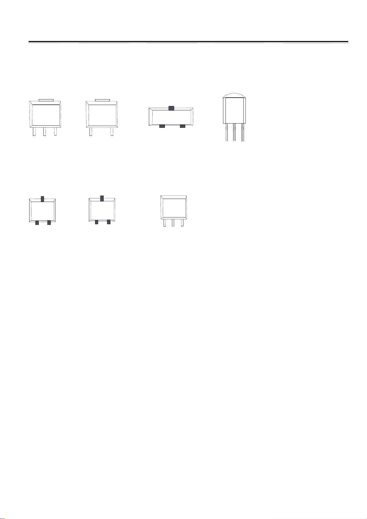
Transistor Mark
AMS1117
GND
OUTPUT
C
S3904
B E
INPUT
MC78
INPUT
S3906
B E
GND
M0
C
5C
OUTPUT
VCC
DT
IMP809
LM
7
8
L
08
GND RESET
GND
OUTPUT
INPUT
LM1086
OUTPUT
INPUT
GND
-13-
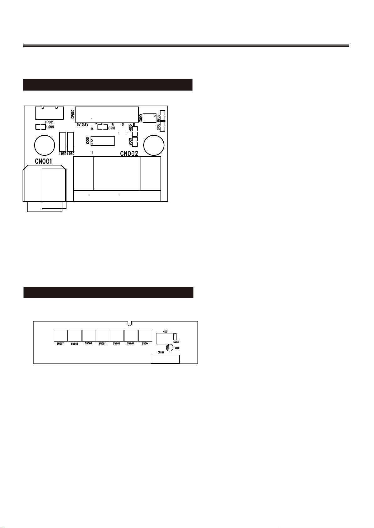
VGA&CONTROL PCB Top Layer
VGA PCB TOP LAYER
CONTROL PCB TOP LAYER
-14-
Service Adjustments
-15-
Service Adjustments
-16-
Control Location
FUNCTIONAL PARTS
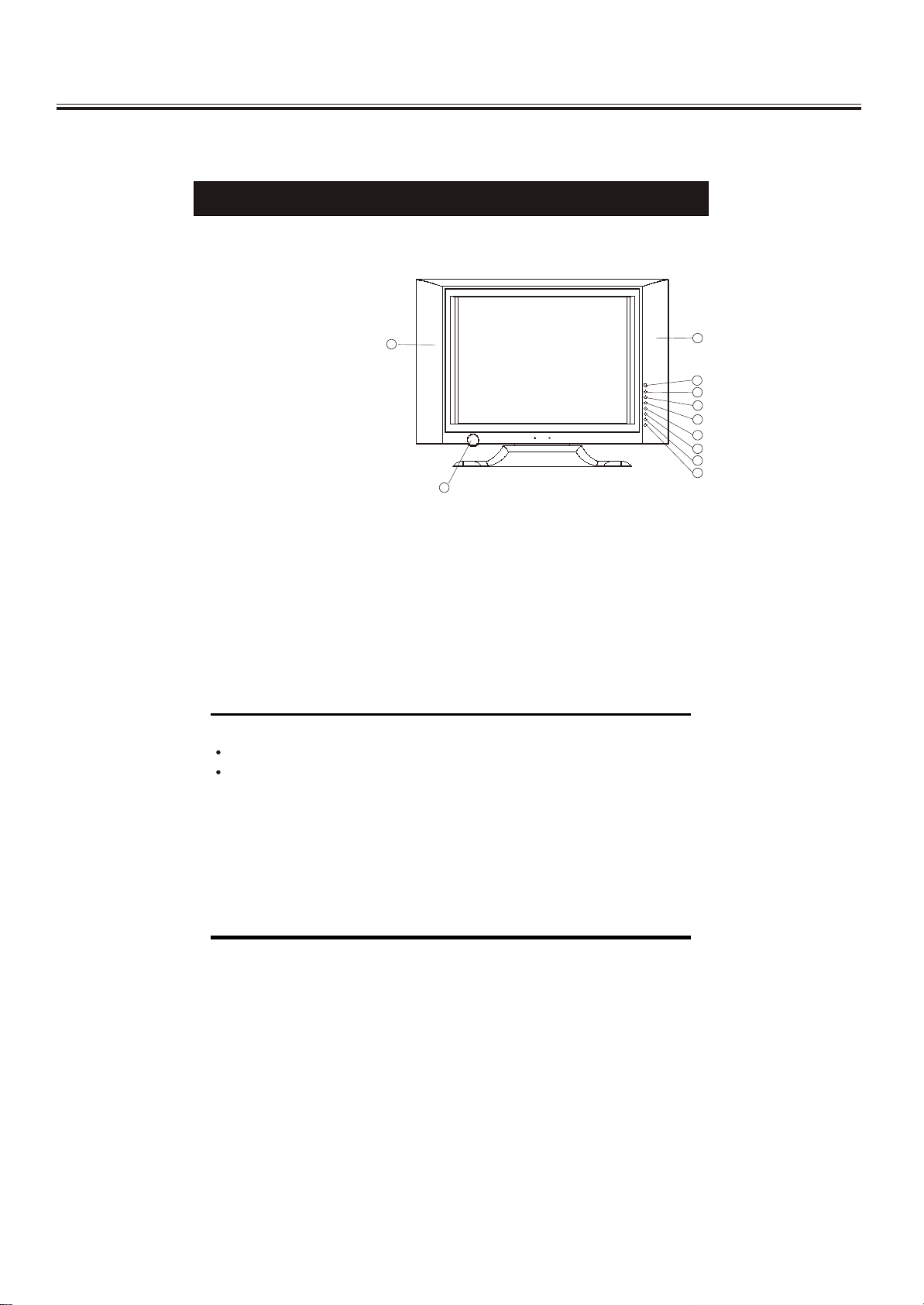
Front View of TV Set
1. Remote Sensor
2. AV Button
3. OK Button
4. Main Menu Button
5. PROG.+Button
6. PROG.- Button
7. VOL.+Button
8. VOL.- Button
9. Power Indicator/Stand by Button
10. Speakers
1010
99
1010
11
22
33
44
55
66
77
88
To turn the TV power ON
Put the TV set on the correct place, then connect the DC plug of the AC-DC adaptor
to the DC 12V socket at the back or the TV set. Connect the adaptor main cord to
the wall outlet, then the power indicator will turn red, the TV set at Standby Mode.
After you press the Standby Button the power indicator will change to green. It need
a few second before the picture appear.
To turn the TV power OFF
Press the Standby Button to make the TV set in Standby Mode., then disconnect
the power plug from the wall outlet.
NOTE
If the TV set does not receive any signal for 5 minutes, it will enter standby mode.
If you are not going to use this TV set for a long time, switch off the set using
the power switch on the TV set and disconnect the power plug from the wall outlet.
-17-
Operation Instructions
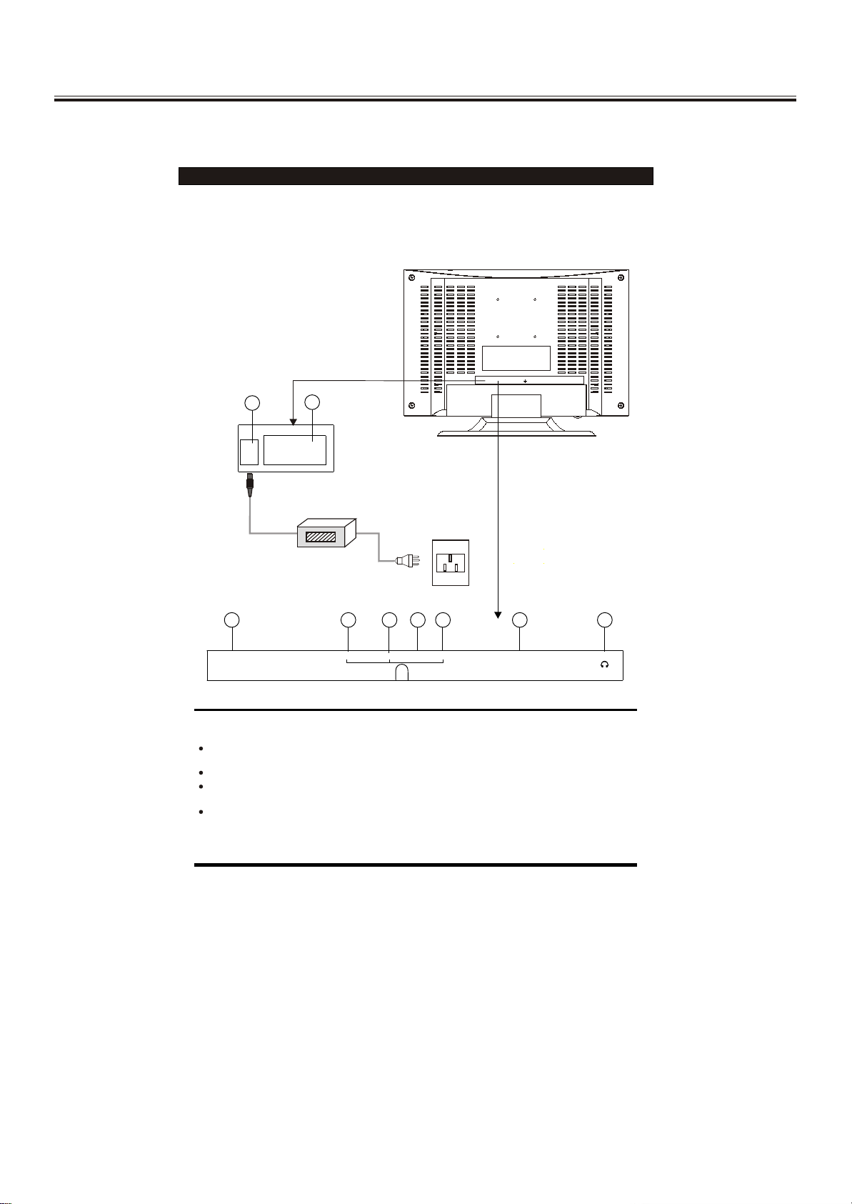
Rear View of TV Set
1. DC 12V In
2. VGA In
AV Audio Right In
3.
4. AV Audio Left In
5. AV Video In
6. S-VIDEO IN
7. Antenna Input Socket(75Ohm)
8. SCART
9. PHONE
11
DC12VDC12V PC INPUTPC INPUT
22
Adaptor
55
66
ANT INANT IN
NOTE
S.VIDEO and AV IN 1 (VIDEO) inputs cannot be used at the same time.
Precautions when connecting to other equipment
When using external equipment with this TV set, please read the instruction
manual of the external equipment.
Switch off all power supplies to the equipment and TV set before connection.
Always ensure that the input and output terminals are correctly connected.
33
4477
VIDEOVIDEOS-VIDEO S-VIDEO PHONE PHONE
LLRR
88
SCARTSCART
99
-18-
Operation Instructions
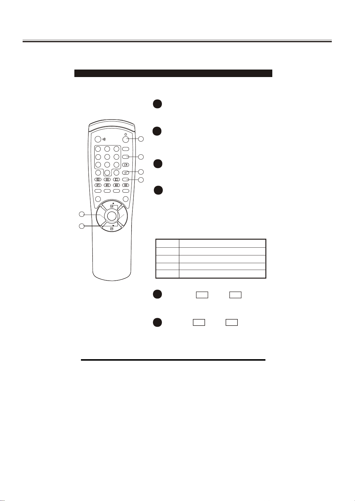
Remote Control Unit
P.M .
SYS
6
9
Q.
VIEW
XX
I/II
HOLD
CH
MENUMENU VOL.+VOL.-
CH
6 6
55
1
2 3
4
5
7
8
- /- -
0
MIX INDEX LANGUAGE
REVEAL SIZE SUB. PAGE
AV OK
1
POWER ON / STANDBY button
Press this button to switch on the TV when
at standby mode.
2
SLEEP button
11
Press this button to set the sleep timer.
When the preset length of time has passed,
the TV set enters standby mode.
33
3
SOUND SYSTEM button
22
44
Press this button to select the correct
sound system.
4
STEREO/BILINGUAL SOUND button (option)
When stereo program is received, press
this button to select STEREO or MONO.
When bilingual program is received, press
this button to select DUAL-1, DUAL-2 or
MONO.
The screen will display NICAM or A2 when
such broadcast is received.
Mode Description
STEREO
MONO
DUAL-1
DUAL-2
Stereo mode.
Mono mode.
Multi-sound channel for language 1.
Multi-sound channel for language 2.
5
CHANNEL UP / DOWN
CH
+
-
CH
buttons
Press these buttons to select channels in
ascending or descending order.
VOL
6
VOLUME UP / DOWN buttons
+
VOL
-
Press these buttons to adjust the volume level
up or down.
-19-
Operation Instructions
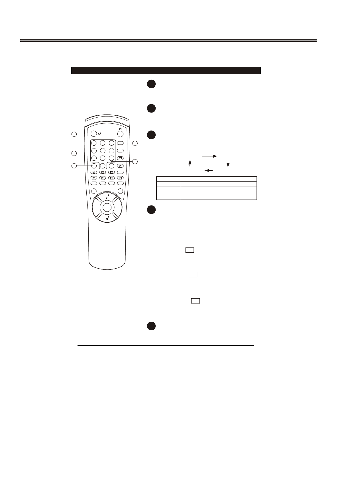
Remote Control Unit
77
1
2 3
4
1111
1010
5
7
8
- /- -
0
MIX INDEX LANGUAGE
REVEAL SIZE SUB. PAGE
AV OK
P.M .
SYS
6
9
Q.
VIEW
XX
I/II
HOLD
CH
MENUMENU VOL.+VOL.-
CH
7
MUTE button
Press once to mute the sound. Press again
to restore the sound volume.
8
QUICK VIEW
button
Press this button to return to the previously
viewed program.
9
PICTURE MODE PICTURE MODE button
99
Press this button to select the desired
picture mode.
CUSTOM RICH
88
STANDARD SOFT
Picture Mode Description
CUSTOM
SOFT
STANDARD
RICH
10
DIGIT button
User preset picture mode.
Low contrast and low brightness level.
Middle contrast and middle brightness level.
High contrast and high brightness level.
This TV allows you to select channels from
0 to 255.
Press this button to select one-digit, twodigit or three-digit channels input options.
To select a one-digit channel (e.g. Channel
8), press this button to change
--/---
channel selection to "-" on screen display
and press the "8" button only.
To select a two-digit channel (e.g. Channel
28), press this button to change
--/---
channel selection to "--" on screen display
and press "2" and "8" buttons.
To select a three-digit channel (e.g. Channel
128), press this button to change
--/---
channel selection to "---" on screen display
and press "1" , "2"and"8" buttons.
11
CHANNEL SELECTION buttons
Press the number buttons to select a channel.
-20-
K
1 2 3
4 5 76 8
J
I
H
G
F
E
D
C
B
A
2 31 54 876
109 11 1312
14 1615
10 119 1312
1614 15
K
J
I
H
G
F
E
D
C
B
A
 Loading...