

Page 1
H-CMD4027
MULTIMEDIA DVD/CD/MP3
RECEIVER WITH BUILT-IN
3.5” TFT DISPLAY AND TV TUNER
МУЛЬТИМЕДИЙНЫЙ
DVD/CD/MP3-РЕСИВЕР
СО ВСТРОЕННЫМ 3.5”TFT-
ДИСПЛЕЕМ И ТВ-ТЮНЕРОМ
Руководство по эксплуатации Instruction manual
Page 2
Table of contents Table of contents
Dear customer!
Thank you for purchasing our product. For safety, it is strongly recommended to read
this manual carefully before connecting, operating and/or adjusting the product and keep
the manual for reference in the future.
Table of contents
Before you start
Utilization of the product
Important safeguards
Installation/Connection
Installation
General notes
Din Front/Rear-Mount
1. DIN front-mount (Method A)
Dismantling the unit
Trim frame installation
2. DIN rear-mount (Method B)
Detachable control panel
Anti-theft system
Connection
Connection diagram
ISO connection table
Using the ISO connector
Parking wire connection
Operation
Control elements
Front panel
Inner panel
Remote controller
Changing battery
General operations
Reset the unit
Turning the unit on/off
Mode selection
Mute function
Volume control
Setting the sound characteristics
System setup
Subwoofer
AV in jack
Radio operations
Band selection
Manual/Automatic tuning
2
Programming stations
4
Auto memory store/preset scan
4
Stereo/mono reception
4
On-screen display
5
RDS background
5
AF (Alternative Frequencies) function
5
TA (Traffic Alarm)/TP function
5
PTY (Program Type)
5
Other functions
6
TV tuner operation
6
Disc/USB/SD/MMC operations
6
USB/SD/MMC notes
6
Insert/Eject disc
6
Inserting a memory card/USB device
7
Play/pause
7
MP3/DivX/JPEG file playback
7
Stop playback
8
Selecting tracks
8
Fast forward/rewind
9
A-B segment repeat
9
Repeat playback
9
Intro playback
9
10
10
11
11
11
11
11
11
11
11
12
12
12
12
12
Goto
Random playback
Programming playback
OSD function
Zooming in/out
PBC function
Changing angle
Selecting audio language
Selecting subtitle language
Selecting sound channel
Menu navigation
ID3 tag information
System setup
System setup
Language setup
Audio setup
12
12
13
13
13
13
13
13
13
14
14
14
14
14
15
15
15
15
15
15
15
15
16
16
16
16
16
16
16
16
16
16
16
17
17
17
17
18
2 3
Page 3

Video setup
Digital setup
General information
Handling compact discs
Cleaning discs
Cleaning the unit body
Accessories
Troubleshooting guide
Specification
18
18
19
19
19
19
19
20
21
Page 4

Before you start
Utilization of the product
If you want to dispose this product, do not mix it with general household waste. There is
a separate collection system for used electronic products in accordance with legislation
that requires proper treatment, recovery and recycling.
Please contact your local authorities for the correct method of disposal. By doing so, you
will ensure that your disposed product undergoes the necessary treatment, recovery and
recycling and thus prevent potential negative effects on the environment and human health.
Important safeguards
• Read carefully through the manual to
familiarize yourself with this unit.
• Keep this manual handy as a reference
for operating procedures and precautions. Do
not allow persons who have not read through
this manual to use this unit.
• “CLASS 1 LASER PRODUCT”
This product contains a laser diode of
higher class than 1. Laser beams from the
optical pickup are dangerous to the eyes. To
ensure continued safety, do not remove any
covers or attempt to gain access to the inside
of the product. Refer all servicing to qualified
personnel.
• Do not allow this unit to come into contact
with liquids. Electrical shock could result. Also,
damage to this unit, smoke, and overheating
could result from contact with liquids or dust.
Protect this unit from moisture.
• Make sure that foreign objects do not get
inside the unit; they may cause malfunctions,
or create safety hazards such as electrical
shock or laser beam exposure.
• The beginning of operation is the moment
of the unit installation. Before use the device
in winter it is recommended to heat up the
passenger compartment during 20 seconds or
to the operation temperature.
• Using the unit with the temperature that
goes beyond the operation temperature greatly
decreases the operation resource of the screen
and other components of the unit and can
result in an outage.
• Disconnect the vehicle’s negative battery
terminal while mounting and connecting the
unit.
• The unit is designed for negative
terminal of the battery, which is connected
to the vehicle metal. Please ensure it before
installation.
• When replacing the fuse, be sure to use
one with an identical amperage rating. Using a
fuse with a higher amperage rating may cause
serious damage to the unit.
• Do not allow the speaker wires to be
shorted together when the unit is switched
on. Otherwise it may overload or burn out the
power amplifier.
• Make sure you disconnect the power
supply and aerial if you will not be using
the system for a long period or during a
thunderstorm.
• Make sure you disconnect the power
supply if the system appears to be working
incorrectly, is making an unusual sound, has
a strange smell, has smoke emitting from it
or liquids have got inside it. Let a qualified
technician check the system.
• Always keep the volume low enough so that
you can hear sounds from outside the vehicle.
• Should this product fail to operate
properly, contact your dealer or nearest service
center.
4
Page 5
Installation/Connection
Installation
General notes
• Choose the mounting location where the
unit will not interfere with the normal driving
function of the driver.
• Before finally installing the unit, connect
the wiring and make sure that the unit works
properly.
• Consult with your nearest dealer if
installation requires the drilling of holes or other
modifications of the vehicle.
• Install the unit where it does not get in the
driver’s way and cannot injure the passenger if
there is a sudden stop, like an emergency stop.
• If installation angle exceeds 30° from
horizontal, the unit may not perform properly.
• Avoid installing the unit where it would
be subject to high temperature, such as from
direct sunlight, or from hot air, from the heater,
or where it would be subject to dust, dirt or
excessive vibration.
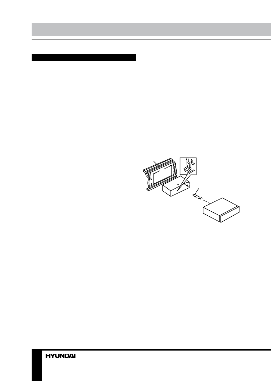
Din Front/Rear-Mount
This unit can be properly installed either
from ‘Front’ (conventional DIN Front-mount) or
‘Rear’ (DIN Rear-mount installation, utilizing
threaded screw Holes at the sides of the unit
chassis). For details, refer to the following
illustrated installation methods.
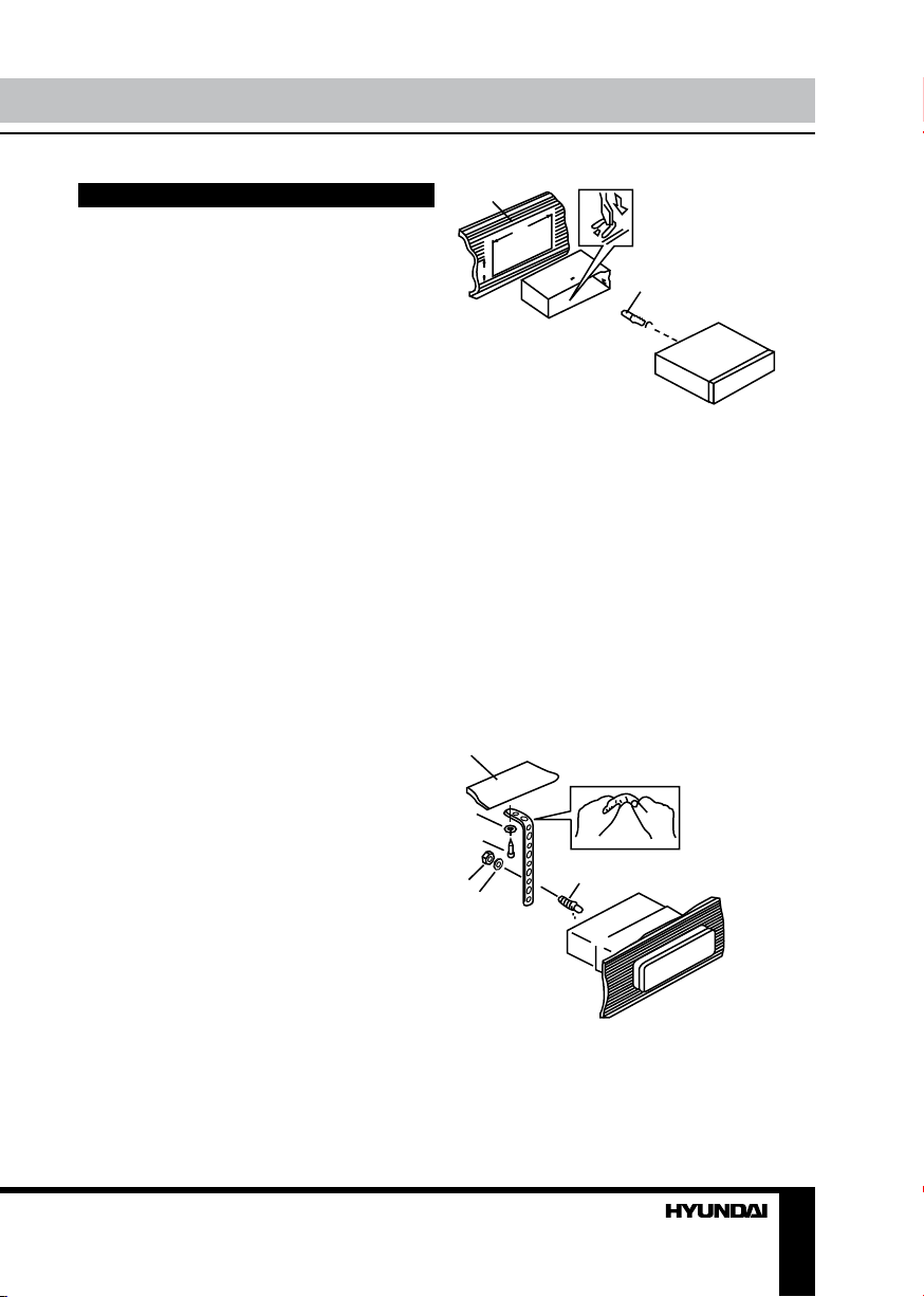
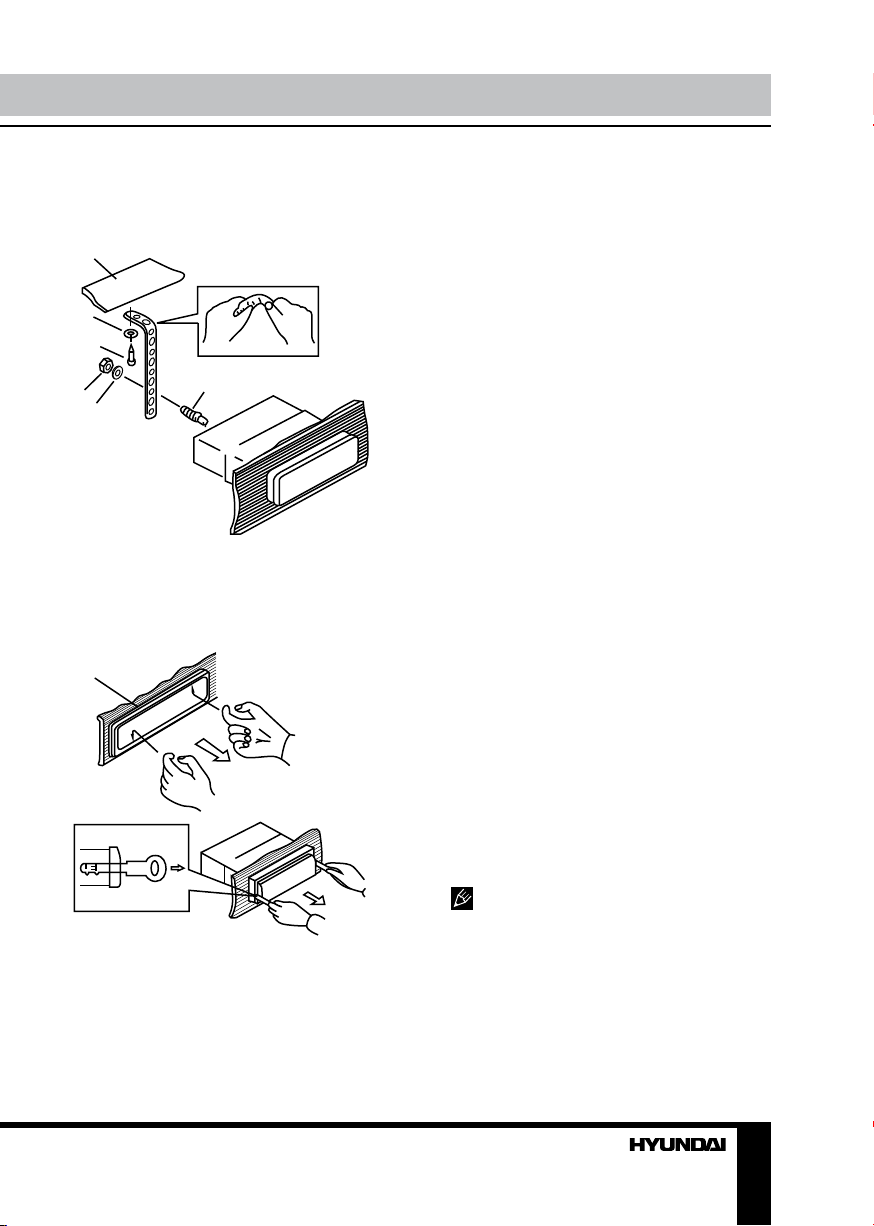
1. DIN front-mount (Method A)
1. Car dashboard
2. Sleeve
3. Screw
4. Nut (5 mm)
5. Spring washer
6. Screw (5 х 25 mm)
7. Metal strap
8. Flat washer
1
182
53
1. Install the sleeve into the dashboard;
ensure it is installed with the correct side and
there are no obstacles (wires, dashboard
elements, etc) for the unit installation.
2. After installing the sleeve into the
dashboard, bend tabs fitting to the size of the
dashboard to fix the sleeve in place.
3. Use the metal strap to fix the rear side of
the unit. Determine a place for fixing and install
the strap as shown in the picture. You can bend
the strap to the needed angle with your hands.
4. Make the necessary wire connections.
Ensure the connections are correct.
5. Install the unit into the sleeve until the side
locks are fixed.
1
8
6
4
5
7
3
2
3
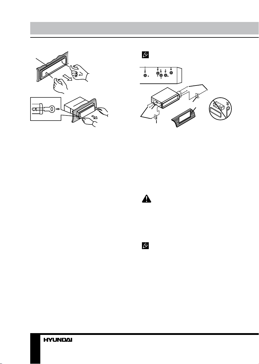
Dismantling the unit
a – Trim frame
b – Frame uninstall direction
c – Release key insertion
5
Page 6
Installation/Connection
а
б
в
1. Switch off the unit and detach the front
panel.
2. Insert your fingers into the groove in the
front side of the trim frame (apply some effort to
detach the frame). Pull the frame to detach it.
3. Insert the supplied release keys into the
both sides of the unit body to click, as shown
in the picture. To extract the unit from the
dashboard, pull the release keys or the unit
body to pull it out. Before detaching the unit,
ensure it is not fixed with the metal strap.
Trim frame installation
To install the trim frame, press it to the unit
body and push it to fix it in place. This should
be done before installing the front panel;
otherwise you are not able to install the trim
frame. When the trim frame being installed,
the side with the groove should face down and
fixed first.
2. DIN rear-mount (Method B)
For this method, use the screw holes in the
lateral sides of the unit. Fix the unit with the
help of the factory radio mounting brackets.
1. Select a position in which the screw holes
of the brackets (3) are aligned with the screw
holes in the unit body, and screw in two screws
(2) in each side.
2. Screw.
3. Factory radio mounting brackets.
4. Vehicle dashboard.
5. Lock (remove this part).
The outer trim frame and mounting
sleeve are not used for method of installation.
2
5
3
4
2
5
Detachable control panel
Insert the left locker on the receiver into the
left groove of the panel, and then insert the
right locker into the right groove. Lift the panel
and press on the upper part of the panel until a
click. Ensure the panel is fixed properly.
To detach the front panel, press OPEN
button. When the panel is in horizontal
position, detach the left part of the panel from
the locker, and then detach the right part.
The control panel can easily be
damaged by shocks. After removing it, place
it in a protective case and be careful not to
drop it or subject it to strong shocks. The rear
connector that connects the main unit and the
control panel is an extremely important part. Be
careful not to damage it by pressing on it with
fingernails, pens, screwdrivers, etc.
If the control panel is dirty, wipe off the
dirt with soft, dry cloth only. And use a cotton
swab soaked in isopropyl alcohol to clean the
socket on the back of the control panel.
Anti-theft system
The front panel of this unit can be stored in
the included protective case when not in used
and carried away when you leave the vehicle
to deter theft.
Switch off the power of the unit. Detach the
front panel, then put it to the protective case
and take it with you.
6
Page 7
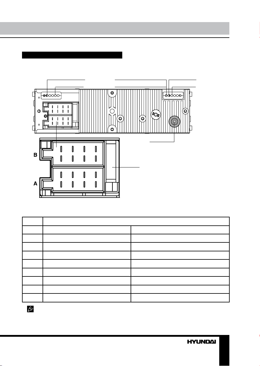
Connection
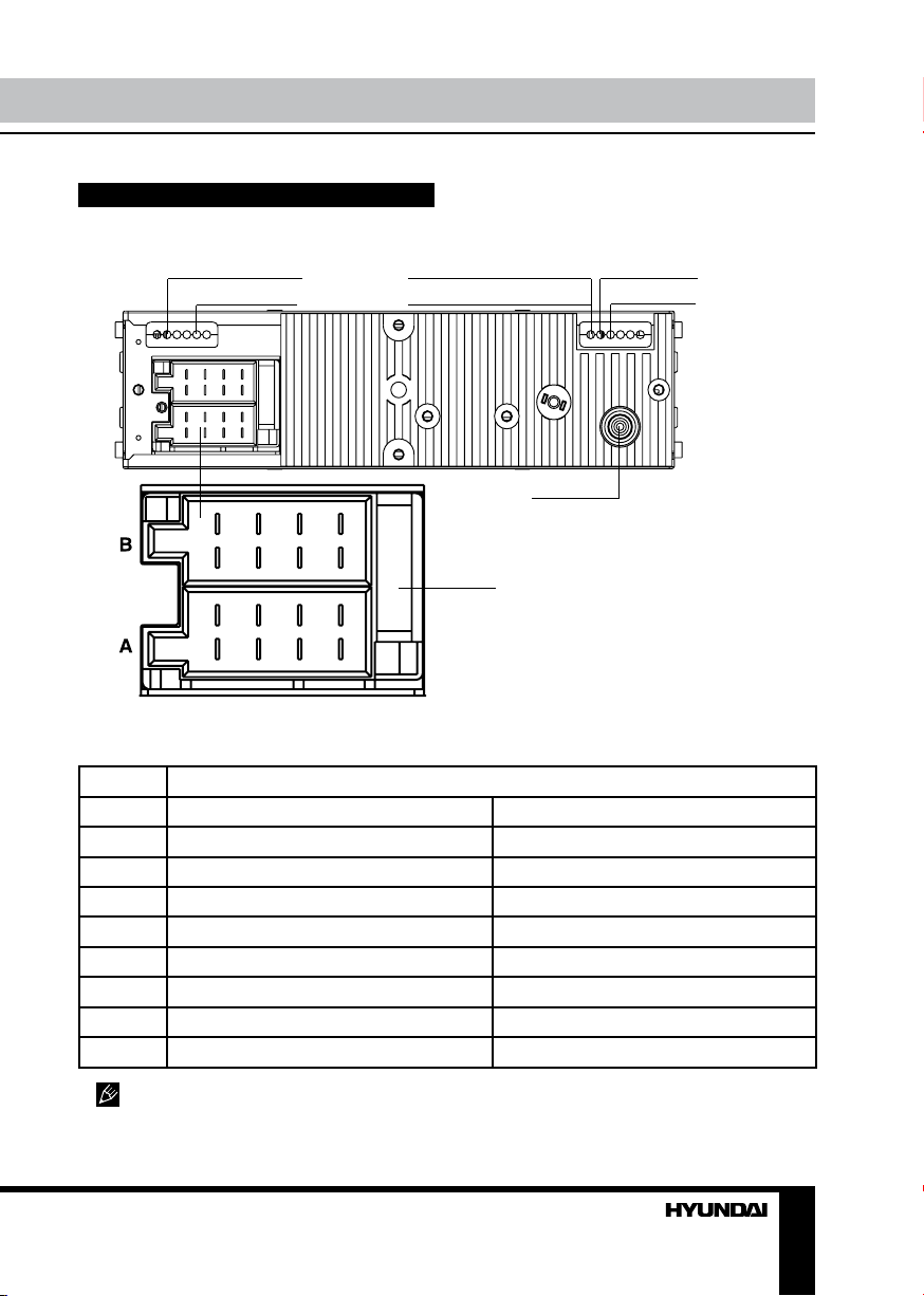
Connection diagram
Video out (yellow) Subwoofer out
Parking wire (brown)
1133557
2244668
ISO connector
Installation/Connection
Line out RCA (red=right)
Line out RCA (white=left)
Antenna jack
Fuse 15 A
7
8
TV antenna
ISO connection table
Location Function
Connector A Connector B
1 - Rear right (+) - Purple
2 - Rear right (-) - Purple/Black
3 - Front right (+) - Grey
4 Battery +12V/Yellow Front right (-) - Grey/Black
5 Power antenna/Blue Front left (+) - White
6 - Front left (-) - White/Black
7 Ignition key (+12V)/Red Rear left (+) - Green
8 Ground/Black Rear left (-) - Green/Black
Power antenna wire is intended for power supply of the antenna and for remote control of
an additional amplifier.
7
Page 8
Installation/Connection Operation
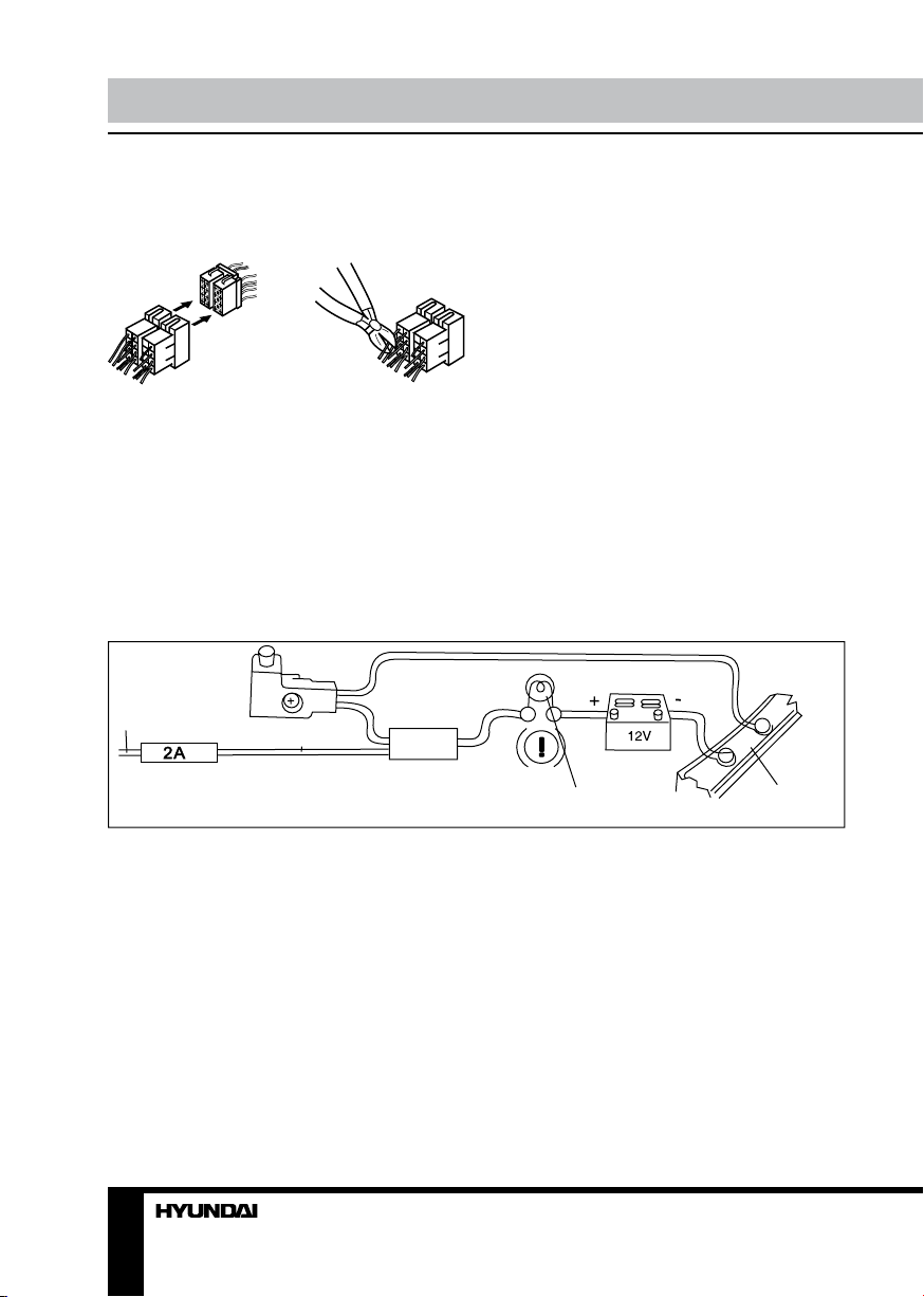
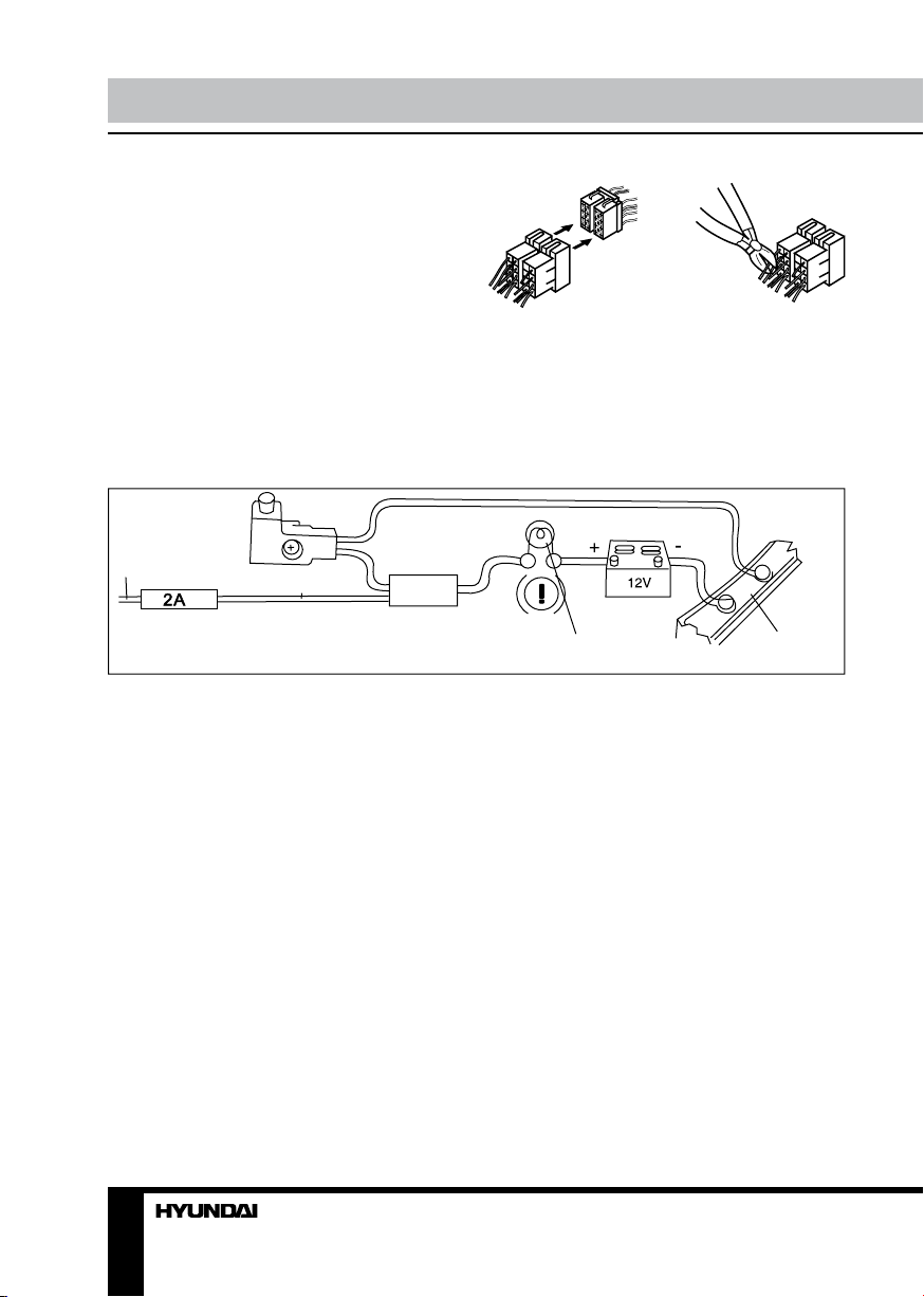
Using the ISO Connector
1. If your car is equipped with the ISO
connector, then connect the ISO connectors as
illustrated.
1 2
2. For connections without the ISO
connectors, check the wiring in the vehicle
carefully before connecting, incorrect connection
may cause serious damage to this unit.
Cut the connector, connect the colored leads
of the power cord to the car battery as shown
in the colour code table above for speaker and
power cable connections.
Parking wire connection
Parking brake lead
If Parking cable is connected to hand brake
switch, the video display of the TFT monitor
will be controlled by driving status. When the
car is moving ahead, if the video disc is played,
the screen shows worning and blank screen.
The warning screen will prevent the driver from
watching images.
8 9
Brown Wire
Brake light
Battery
Car frame
Page 9
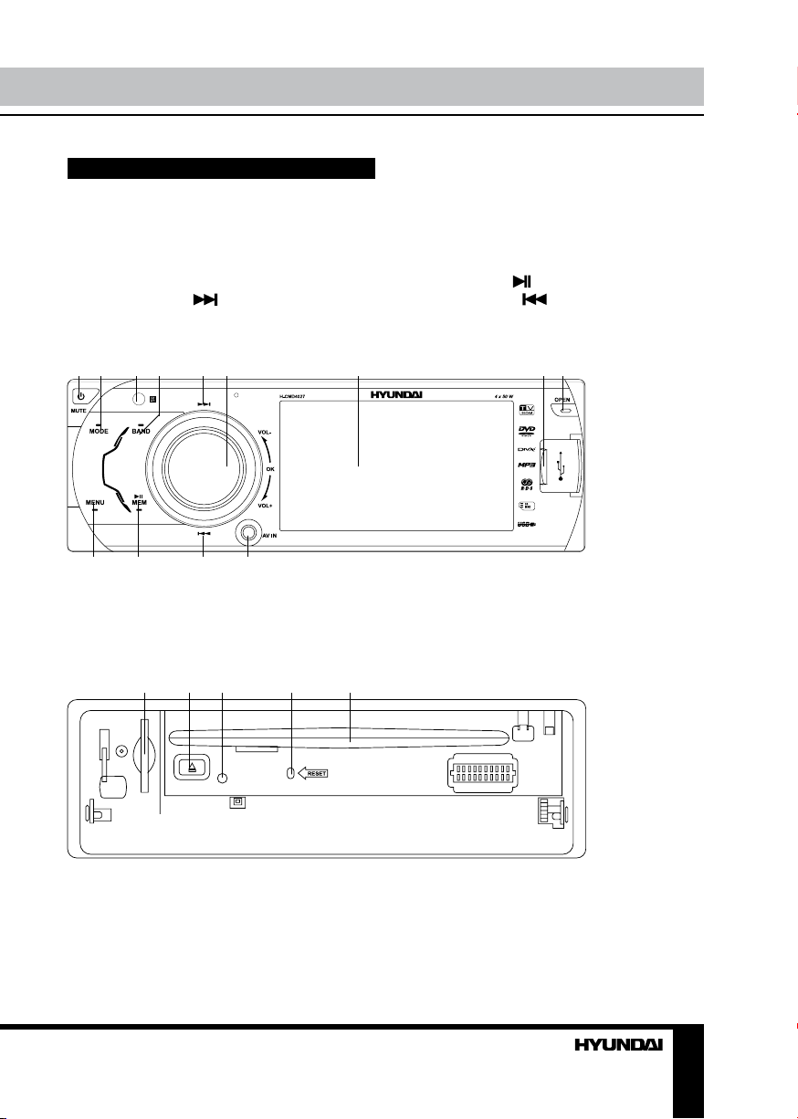
Control elements
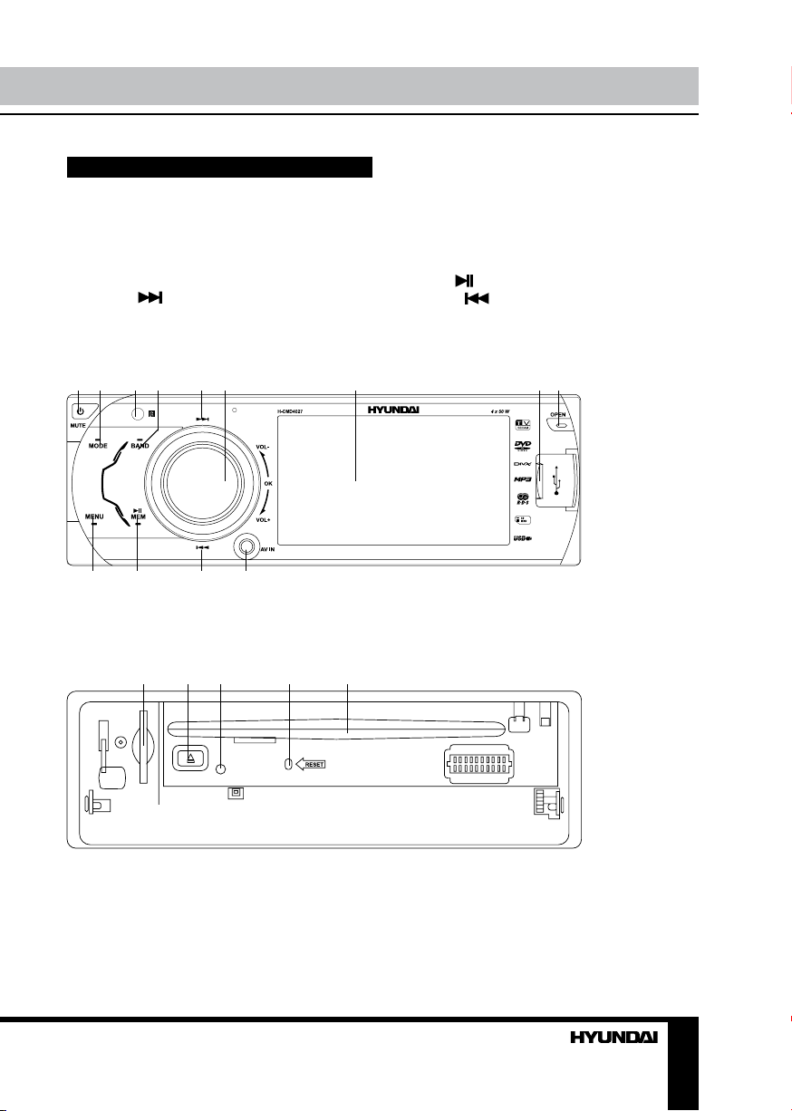
Front panel
1. POWER/MUTE button
2. MODE button
3. IR sensor
4. BAND button
5. SEEK+ button
6. OK button/VOLUME knob
7. Display
1
2 3 4 5 6 7 8 9
10 11 12 13
8. USB port
9. OPEN button
10. MENU button
11. MEM/
12. SEEK- button
13. AV input
button
Inner panel
1 2 3 4 5
1. Memory card slot
2. Eject button
3. Panel status indicator
4. RESET button (hole)
5. Disc loading slot
Pressing RESET hole will erase the clock
setting and stored stations.
Panel status indicator lights up when you flip
down the panel and flashes when you remove
the panel.
Page 10
Operation
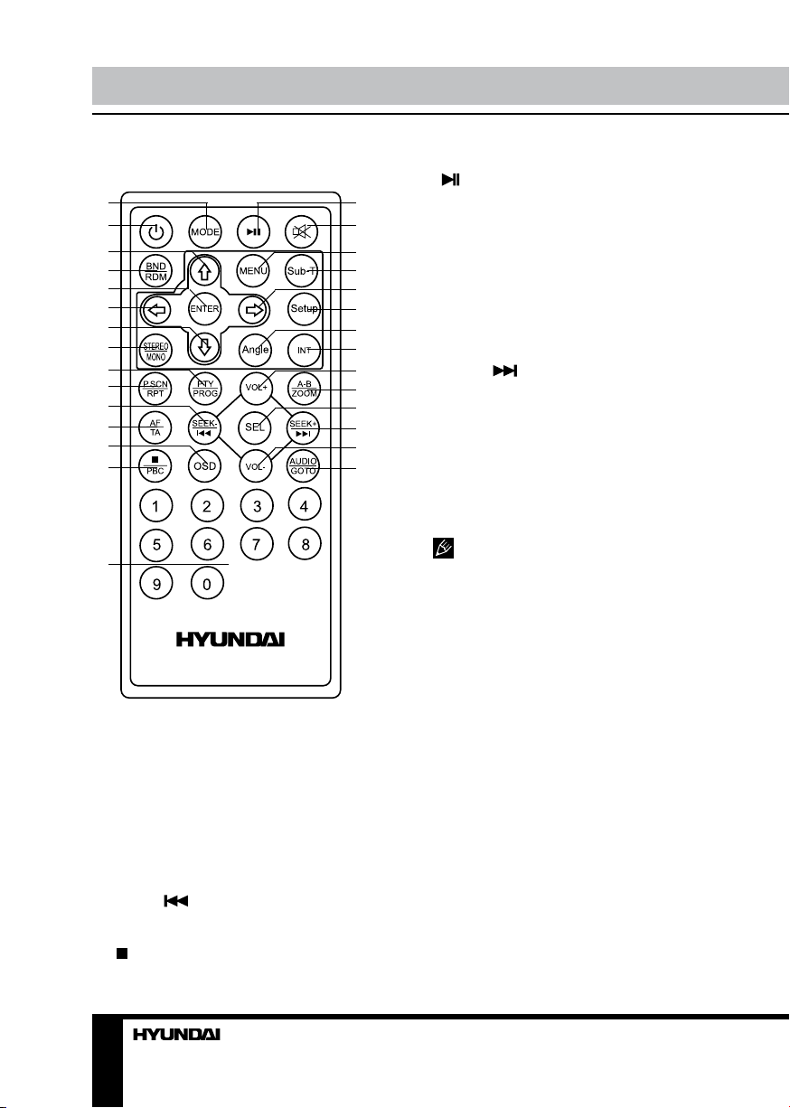
Remote controller
1
2
3
4
5
6
7
8
9
10
11
12
13
14
15
1. POWER button
2. MODE button
3. UP cursor button
4. BND/RDM button
5. ENTER button
6. LEFT cursor button
7. DOWN cursor button
8. STEREO/MONO button
9. PTY/PROG button
10. P.SCN/RPT button
11. SEEK- button
12. AF/TA button
13. OSD button
14. /PBC button
15. Number buttons
button
16.
16
17
18
19
20
21
22
23
24
25
26
27
28
29
17. MUTE button
18. MENU button
19. SUB-T button
20. RIGHT cursor button
21. SETUP button
22. ANGLE button
23. INT button
24. VOL+ button
25. A-B/ZOOM button
26. SEL button
27. SEEK+ button
28. VOL- button
29. AUDIO/GOTO button
Changing the battery
1. Press the catch and at the same time pull
out the battery tray.
2. Insert the 1 x lithium battery, type CR
2025 3 V with (+) mark facing up. Insert the
battery tray into the remote control.
• Store the battery where children
cannot reach. If a child accidentally swallows
the battery, consult a doctor immediately.
• Do not recharge, short, disassemble or
heat the battery or dispose it in a fire.
• Do not expose or bring into contact the
battery with other metallic materials. Doing this
may cause the battery to give off heat, crack or
start a fire.
• When throwing away or saving the battery,
wrap it in tape and insulate; otherwise, the
battery may give off heat, crack or start a fire.
• Please direct the Remote controller to the
IR sensor of the front panel.
10
Page 11
Operation
General operations
Reset the unit
Operating the unit for the first time or after
replacing the car battery, you must reset the
unit. Press RESET button (hole) with a pointed
object (such as a ballpoint pen) to set the unit
to initial state.
When some errors occur, you can also
press RESET button to resume to normal,
and it will erase the clock setting and some
memorized functions.
Turning the unit on/off
Press any button on the panel or the RC
(except OPEN button) to turn on the unit. Press
and hold POWER/MUTE button on the panel
or press POWER button on the RC to turn off
the unit.
Mode selection
Repeatedly press MODE button on the RC
or on the panel to select a mode: Tuner =>
DVD => USB => Card => TV => AV IN.
The DVD, Card and USB modes are
only available when corresponding storages
are inserted into the unit.
Mute function
Press MUTE button on the RC or POWER/
MUTE button on the panel to turn off the
sound. “MUTE” appears on the display. Press
the button again or adjust volume to resume
the sound output.
Volume control
Press VOL+/VOL- buttons on the RC or
rotate VOLUME knob on the panel to decrease
or increase sound volume level.
Setting the sound characteristics
Press SEL button on the RC to select the
audio setting menu: BASS =>TREBLE =>
BALANCE => FADER => EQ. Press UP/
DOWN cursor buttons on the RC or rotate
VOLUME knob on the panel to select the audio
setting item. Press ENTER button or RIGHT
cursor button on the RC or OK button on the
panel to enter the selected item.
Press LEFT/RIGHT buttons on the RC or
rotate VOLUME knob on the panel to adjust the
audio setting. Press SEL button on the RC again
to save the setting and return to current mode.
If turn off the power, all the settings
of each mode will be saved. If turn off the
ACC power, all the settings will be clear and
become factory default setting. If you don’t
adjust setting within several seconds after
selecting the desired setting item, the unit will
automatically return to the current mode.
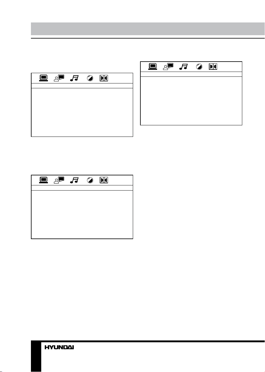
System setup
Press MENU button on the panel or RC to
enter Setting Menu. Press UP/DOWN cursor
buttons on the RC or rotate VOLUME knob on
the panel to select a menu page. Press ENTER
button or RIGHT cursor button on the RC or
press OK button on the panel to enter the page.
Press UP/DOWN cursor buttons on the RC or
rotate VOLUME knob on the panel to select an
item, then press ENTER button on the RC or OK
button on the panel to adjust the setting.
Press MENU button to return to the last
setting list.
AUDIO MENU
• Bass: Support 10 levels. Default level is 0.
• Treble: Support 10 levels. Default level is 0.
• Balance: Support 10 levels for each left
and right channel. Default is left equal to right.
• Fader: Support 10 levels for each front and
rear channel. Default is front equal to rear.
• EQ DSP: FLAT => CLASSICS => POP =>
ROCK => DSP OFF.
PICTURE MENU (available in DVD/USB/
Card modes only)
• Red: Adjust level of red color. Support 50
levels. Default level is 25.
• Green: Adjust level of green color. Support
50 levels. Default level is 25.
• Blue: Adjust level of blue color. Support 50
levels. Default level is 25.
• Brightness: Adjust level of screen
11
Page 12
Operation Operation
brightness. Support 50 levels. Default level is 25.
• Contrast: Adjust level of screen contrast.
Support 50 levels. Default level is 25.
• Sharpness: Adjust level of screen
sharpness. Support 15 levels. Default level is 10.
• Screen: Adjust screen aspect: 16:9 => 4:3
=> FULL.
• Color reset: Resume color default status.
(Select YES or NO with cursor buttons, press
ENTER button on the RC or OK button on the
panel to confirm).
EXPERT MENU
• DX: Set search radio station by DX or
LOCAL mode. DX => LOCAL.
• Stereo: Set radio audio at STEREO or
MONO mode, STEREO => MONO.
• Beep: Set press button sound. 2ND =>
ALL => OFF.
• Loud: Set loudness on or off. OFF => ON.
• Subwoofer: Set dubwoofer ON or OFF.
• Backlight: Set OSD backlight: HIGH =>
LOW => MID.
• OSD color: Set OSD color: DARK BLUE
=> VIOLET => LIGHT BLUE.
CLOCK MENU
• Clock: Set CLOCK display time or not.
OFF/ON.
• Clock Hour: set clock 12H/24H.
• Clock adjust: Set CLOCK ADJUST time.
Subwoofer
Connect a subwoofer to this unit using the
Subwoofer output of this unit. For subwoofer
operation an external amplifier is required.
AV in jack
AV jack is intended to receive audio and video
signals by connecting to external device.
Radio operations
Band selection
Press BND/RDM button on the RC or BAND
button on the panel to switch to the bands in
the following order: FM1 - FM2 - FM3 (OIRT) –
MW (AM).
Manual/automatic tuning
• Manual tuning: Press and hold SEEK- /
SEEK+
tuning mode. MANUAL will be displayed.
Press these buttons repeatedly to change the
frequency upward or downward step by step.
• Automatic tuning: Press repeatedly
SEEKpress and hold these buttons on panel to start
automatic seeking for an available radio station
downward or upward. After being found the
station will be played. To stop seeking, press
one of these buttons again.
buttons on the RC to enter manual
/SEEK+ buttons on the RC or
Programming stations
• There are 6 numbered preset buttons on
the RC, with which you can store and recall
stations for each band (18 FM, 6 AM). Select
a station, then press and hold a preset button.
The station will be saved in the memory under
the corresponding number. To recall a stored
station, press the corresponding preset button.
• You also can save stations in the memory
with MEM/
the needed frequency is found, press MEM/
then rotate VOLUME knob to select a memory
position (PRESET 1 - 6) and press OK button
to confirm saving.
button on the front panel. When
Auto memory store/Preset scan
Auto store: Select a band, press and hold
P.SCN/RPT button on the RC to enter auto
store mode. The radio will automatically store 6
stations to the 6 preset memories of the current
band. To stop auto store, press the button
again.
During auto station preset, the unit will
search and store stations with the strong signal
first, and then weaker signal stations until the
memories are full.
Preset scan: Select a band, press P.SCN/
RPT button on the RC to scan all preset
stations in the memories of the current band.
To stop preset scan, press the button again.
,
12 13
Page 13
Stereo/Mono reception
In FM mode, press STEREO/MONO button
on the RC to select stereo or mono signal
reception mode.
On-screen display
Press OSD button on the RC to show
enabled PTY function icon.
RDS background
RDS service availability varies with areas.
Please understand if RDS service is not
available in you area, the following service is
not available.
AF (Alternative frequencies) function
Press and hold AF/TA button on the RC
or MENU button on the panel to enable AF
function. When the radio signal strength is poor,
enabling the AF function will allow the unit to
automatically search another station with the
same PI (Program Identification) as the current
station but with stronger signal strength.
AF indicator on the display will flash until
RDS information is received. If RDS service is
not available in your area, turn off the AF mode.
TA (Traffic alarm) function
Press AF/TA button on the RC or press and
hold OK button on the panel to activate the
traffic alarm function.
When TA function is activated, it will search
the station with TA information automatically.
If there is no TA information, it will search the
station with TP information automatically, if
there is no TP information either, it will return to
the previous station after searching.
When receiving the station with TP
information but without TA information,
TP icon is on and TA icon keeps blinking;
when receiving the station with TP and TA
information, both TP and TA icons are on.
When playing in other mode and TA
information is received, it will change to the
radio mode automatically. After playing over, it
will return to the previous mode. Press AF/TA
button on the RC once to ignore the received TA
information, do it twice to turn off the function.
PTY (Program type) function
Press PTY/PROG button on the RC to open
PTY program type list, and repeat pressing
PTY/PROG button to select a PTY type. After
selecting the program type you want, press
number buttons 1 - 6 on the RC to start search.
Press it again to stop the PTY search. If PTY
code is different or not available, “PTY NONE”
blinks on the display.
Other functions
Press MENU button on the panel or RC to
enter Setting Menu. Press UP/DOWN cursor
buttons on the RC or rotate VOLUME knob on
the panel to select RDS SETUP page. Press
ENTER button or RIGHT cursor button on the
RC or press OK button on the panel to enter the
page. Press UP/DOWN cursor buttons on the RC
or rotate VOLUME knob on the panel to select an
item, and then press SEL button on the RC or Ok
button on the panel to adjust the setting.
Press ENTER button on the RC or OK
button on the panel to confirm, press MENU
button to return to last settings list.
RDS SETUP
• TA ALARM/SEEK: In TA SEEK mode, the
unit will seek for traffic announcement program;
in TA ALARM mode, the alarm is set off.
• PI SOUND/MUTE: Choose either PI sound
or PI mute. PI sound refers to the reception
noise when the AF function tries to scan
alternative frequency.
• RETUNE S/L: RETUNE refers to the time
period the unit allows for radio scan when
reception is interrupted. SHORT represents
a time period of 30 seconds and LONG
represents a time period of 90 seconds.
• MASK DPI/ALL: During MASK DPI mode,
the unit will mask only the AF which has
different PI, this is the default mode; during
MASK ALL mode, the unit will mask the AF
which has different PI and no RDS signal with
high field strength.
• EON TA DX/LOCAL: EON (Enhanced
Page 14
Operation
Other Networks) - This unit is equipped with
the latest technology of EON control, so that
when you are listening to Radio or CD, if there
is any travel announcement from a nearby
local station, the radio will already know the
frequency of that radio station. Then it will
receive the station, turn up the volume, or
interrupt the playback for the duration of the
announcement. At the end of the announcement
the radio will return to its previous state ready
for the next announcement.
• REG ON/OFF: When REG is available (On),
the receiver accepts regional variants of the
tuned station display. When REG is unavailable
(Off), the receiver ignores regional variants.
• TA VOL: You can set the default volume of
TA announcement. Support 50 levels. Default
level is 15.
TV tuner operations
• Connect the TV antenna to the TV antenna
jack on the rear of the unit. Select TV mode.
• To access the TV mode menu, press
MENU button. To select a menu page (Auto
Program or Manual Program) press UP/DOWN
cursor buttons on the RC or rotate VOLUME
knob on the panel. To enter the selected page
press OK button on the panel or ENTER button
on the RC. Press UP/DOWN cursor buttons on
the RC or rotate VOLUME knob on the panel to
select an item, and then press ENTER button
on the RC or OK button on the panel to adjust
the setting. Press MENU button to return to last
settings list.
AUTO PROGRAM
• System: select TV system (SECAM1/
SECAM2/PAL).
• Audio: select sound system (DK/BG/I).
• Search: select to start automatical search
and storing of TV channels.
MANUAL PROGRAM
• Storage: select the storage number of the
channel.
• System: select TV system (SECAM1/
SECAM2/PAL).
• Audio: select sound system (DK/BG/I).
• Channel: Select the number of the channel.
• Fine: perform fine tuning of picture quality.
• Memory: select on (memorize the found
channel) or off (not memorize).
TV image cannot be displayd on the
external monitor.
Disc/USB/SD/MMC operations
USB/SD/MMC notes
USB format supports 2.0. Capacity: up to 8
Gb.
For correct and satisfactory operation,
licensed SD/MMC memory cards of famous
brands should be used with this unit. Avoid
using memory cards of unknown brands.
Capacity: up to 8 Gb.
Insert/Eject disc
• Open the front panel and insert a disc into
the disc slot with label side up. The disc will be
automatically loaded into the unit. The first file
in the root folder will be played. Close the front
panel.
• Open the front panel and press EJECT
button to eject the disc from the slot. If the disc
is not removed from the slot within several
seconds, it will be automatically loaded into
the slot again. When the disc is ejected and
removed, the unit will automatically switch to
another mode.
Inserting an SD/MMC card/USB device
Open the front panel and insert an SD/
MMC memory card into the card slot. Open the
USB slot cover on the front panel and insert
a USB into the USB slot. Then the playing
mode will be changed into Card or USB mode
automatically. The first card/USB device track
playback will start.
When SD/MMC card and USB device are
both inserted, the playing mode will be changed
into the mode of the device inserted later.
14
Page 15

Operation
Play/pause
The unit will automatically play from the first
sound track recorded on a disc/SD/MMC/USB
device. To ensure good system performance,
wait until the unit finishes reading the disc/
device information before proceeding. Press
button on the RC or MEM/ button on
the panel to pause playback, press it again to
resume playback.
MP3/DivX/JPEG file playback
When you insert a storage containing MP3/
DivX/JPEG file, the screen will show following
interface:
1 2 3 4 5
6 7 8
1. Storage folder list
2. Scroll bar
3. Current playback info
4. Current folder content (current file is
highlighted)
5. Scroll bar
6. Audio track selection
7. Image file selection
8. Video file selection
Use cursor buttons to navigate in the
interface and press ENTER button to confirm
your selection.
Some AVI files cannot be played due
to their parameters and recording conditions.
Video files more than 2 Gb having AVI
extension can be played partially.
Stop playback
During playback of a disc/USB/SD/MMC
card, press /PBC button on the RC or press
and hold MEM/
playback. Press
the unit to start playback again. Playback will
resume from the point it was stopped at. If you
press /PBC button on the RC or press and
hold MEM/ on the panel twice, playback will
stop completely and can be resumed only from
the beginning of the disc.
on the panel to stop the
button on the RC or on
Selecting tracks
During playback press SEEK- button to
play the
beginning of current track, press it again
to play the previous track. Press SEEK+
button to play the next track. Press number
buttons (0-9) on the RC to select the desired
track/chapter.
Fast forward/rewind
Press and hold SEEK- or SEEK+
buttons repeatedly for fast backward or forward
playing correspondingly. With each pressing
and holding playback speed will increase.
While fast playback, press
RC or MEM/ button on the panel to resume
normal speed.
When fast backward/forward playback
reaches the previous or next track, the unit will
resume normal playback.
button on the
A-B segment repeat
Press A-B/ZOOM button to set point A,
press one more time to set point B and start
A-B repeating. Press this button one more time
to cancel the repeating function.
Repeat playback
Press P.SCAN/RPT button repeatedly for
repeat playing in different modes: track/chapter
repeat, folder repeat, disc repeat, repeat cancel
(depending on the format used).
Intro playback
Press INT button on the RC to activate
15
Page 16

Operation
introduction function. Several initial seconds
of each track will be played. Press the button
again to cancel intro playback.
GOTO
Press and hold AUDIO/GOTO button to
show the playback parameters for the current
chapter/track/time (track/title/chapter number or
time). Press cursor buttons to navigate between
the parameters and use number buttons to
input needed settings. Press OK button on
the panel or ENTER button on the RC to start
playback from the set number or time.
Random playback
Press BND/RDM button on the RC to
activate random playing mode. Press one more
time to return to normal playing.
Programming the playback
• Press PTY/PROG button to open program
menu.
• Use cursor buttons to select the program
position and use number buttons to input the
desired track/title/chapter (depending on the
disc type).
• Press
button on the panel to start program play, or
move the cursor to select PLAY and press
ENTER button on the RC or OK button on the
panel to play.
• Move the cursor to CLEAR, press ENTER
button on the RC or OK button on the panel to
delete the programmed list. Press PTY/PROG
button to quit programming.
button on the RC or MEM/
OSD (On Screen Display) function
Press and hold OSD button on the
RC repeatedly to show current playback
information, such as number of track/chapter/
title, current track/chapter/title time elapsed/
remaining, total track/chapter/title time
remaining (depending on the disc type).
Zooming in/out
During playback of video or images on disc/
USB/SD/MMC, press and hold repeatedly
A-B/ZOOM button on the RC, the picture will
be zoomed in the sequence: X2 =>X3 =>X4
=>X1/2 => X1/3 => X1/4 => Normal.
PBC (Playback Control) function (for
VCD only)
This function is only available for the VCD
with PBC function.
Press and hold
set PBC on/off; when PBC is off, the screen will
show PBC menu if you switch PBC on. If the
menu consists of a list of titles, you can select a
desired one using number buttons on the RC.
/PBC button on the RC to
Changing angle (for DVD only)
Press ANGLE button on the RC to playback
images at different camera angles. If a disc
doesn’t support multi-angle playback, this
function will not work.
Selecting audio language (for DVD only)
During DVD disc playback, press AUDIO/
GOTO button on the RC repeatedly to select
the audio language to listen. This function will
not work if a disc does not support multilanguage audio.
Selecting subtitle language (for DVD
only)
If your DVD disc supports multi-language
subtitle, press SUB-T button on the RC
repeatedly to switch among disc-supported
languages.
Selecting sound channel (for VCD only)
During VCD disc playback press AUDIO/
GOTO button on the RC to select the channel:
Mono L => Mono R => MIX Mono => Stereo.
Menu navigation (for DVD only)
Press and hold MENU button on the RC
to activate the disc menu list on the screen.
Choose the desired item. Press ENTER button
or
button on the RC or OK button on the
panel to confirm the selected item and start
16
Page 17

Operation
playing.
Title and menu are only available if the
disc has these functions.
ID3 Tag function
If a MP3 file has ID3 tag information in the
supported ID3 format, such information will be
displayed on the LCD while playback
System setup
Press SETUP button on the RC to display
setup screen, use LEFT/RIGHT cursor buttons
and ENTER button to select the desired setup
page: System, Language, Audio, Video, Digital.
In the selected page select an option using
UP/DOWN cursor buttons, then press RIGHT
cursor button to go to setting list. Use UP/
DOWN cursor buttons to select the needed
setting. Press ENTER button on the RC or OK
button on the panel to confirm.
System setup
SYSTEM SETUP
TV SYSTEM
SCREEN SAVER
VIDEO
TV TYPE
PASSWORD
RATING
DEFAULT
TV system
Select the TV system in the setting menu
(NTSC, PAL, PAL-60, AUTO).
Screen saver
The screen saver appears if disc stops for
more than 3 minutes. Original setting: On.
Video
Interlace-S-Video
TV type
Select TV type to watch wide screen movies.
4:3 PS: For 4:3 TV, left and right edges will
be cut.
4:3 LB: For 4:3 TV, black bars will appear on
top and bottom.
16:9: For 16:9 wide screen TV.
Password
Original password is 0000.
Rating
The rating of the disc is from 1 to 8:
1 (KID SAFE) with the most limits when
playing.
8 (ADULT) with the least limits when playing.
Original setting: 8.
The rating can be selected only under the
password unlocked status, and the limits can be
worked only under the password locked status.
Default
If this item is selected, the unit will return to
original setting.
Language setup
LANGUAGE SETUP
OSD LANGUAGE
AUDIO LANG
SUBTITLE LANG
MENU LANG
DIVX [R] VOD
OSD language
Select the language to be used for the on-
screen display.
Audio language
Select the language to be used for the audio.
You can select a preferred audio from those
included on the DVD video disk.
Subtitle language
Select the language to be used for the
Subtitles. You can select a preferred subtitle
from those included in the DVD Video disk.
Menu language
Select the language to be used for the Menu.
You can select a preferred audio from those
17
Page 18
Operation
included on the DVD.
Audio setup
AUDIO SETUP
KEY
Key
Select key up/down according to your
preference.
Video setup
VIDEO SETUP
BRIGHTNESS
CONTRAST
HUE
SATURATION
SHARPNESS
Digital setup
DIGITAL SETUP
DYNAMIC RANGE
DUAL MONO
Dynamic range
When you select the compressed mode as
“line out”, select it to adjust the compression
proportion and get the different compressed
effect. When select FULL, the audio signal is
minimum; when select OFF, the audio signal is
maximum.
Dual mono
Select the audio channel from STEREO,
MONO L, MONO R and MIX MONO.
Set a parameter with UP/DOWN cursor
buttons: Brightness, Contrast, Hue, Saturation,
Sharpness.
18
Page 19

General information
Handling compact discs
• Do not insert anything other than a CD into
the CD loading slot.
• Do not use cracked, chipped, warped, or
otherwise damaged discs as they may cause
skipping or noise damage the player.
• Handle the disc only by the edges (as
shown in the picture). To keep discs clean do
not touch its surface.
• Store discs in their cases when not in use.
• Do not expose discs to direct sunlight,
high humidity, high temperature or dust.
• Prolonged exposure to extreme
temperature (such as leaving the discs in your
car during summertime) can wrap a disc.
• Do not attach labels, write on or apply
chemicals to the surface of the discs.
• Do not touch the recorded surface of the
discs.
• Use 12-cm CDs. Use only conventional,
fully circular discs. Do not use shaped discs.
Cleaning discs
Fingerprints should be carefully wiped from
the surface of disc with a soft cloth. Unlike
conventional records, compact discs have no
grooves to collect dust and macroscopic dirt,
so gently wiping them with a soft cloth should
remove must panicles. Wipe in a straight
motion from the center to the edge.
Never use thinner benzine, record cleaner
or anti static spray on a compact disc. Such
chemicals can damage its plastic surface.
Cleaning the unit body
Wipe with a soft cloth. If the cabinet is very
dampen (not dropping wet) the cloth with a
weak solution of soapy water, and then wipe
clean.
Accessories
1. Receiver
2. Front panel
3. Protective case
4. Remote controller
5. ISO connector set (A+B)
6. Mounting parts:
Nut
Spring washer
Flat washer
Bolt
Screw
Metal strap
Release key
Trim frame
Rubber cushion
7. Instruction manual
8. Warranty card
9. Consumer information
1 pc
1 pc
1 pc
1 pc
1 pc
1 pc
1 pc
1 pc
1 pc
4 pcs
1 pc
2 pcs
1 pc
1 pc
1 pc
1 pc
1 pc
19
Page 20

General information General information
Troubleshooting
Below is a table describing simple measures that can help you eliminate most problems likely
to emerge when this unit is in use. If below measures do not help, turn to a service center or to the
nearest dealer.
Symptom Cause Solution
No power The car ignition is not on. If the power supply is properly connected
The fuse is blown. Replace the fuse.
No sound Volume is in minimum. Adjust volume to a desired level.
Wiring is not properly
connected.
Bad sound quality The installation angle is more
Disc cannot be
loaded or ejected
Disc cannot be
read
Buttons do not
work
The radio does
not work
The radio station
automatic tuning
does not work
than 30 degrees.
The disc is extremely dirty or
defective.
The unit already contains a
disc.
Moisture condensation. Leave the unit idle for an hour, then retry.
The disc is inserted upside
down.
Compact disc is extremely
dirty or defective.
Temperature inside the car is
too high.
The built-in microcomputer is
not operating properly.
Front panel is not properly fix
into its place.
The antenna cable is not
connected.
The signals are too weak. Select stations manually.
to the car accessory switch the ignition
key to “ACC”.
Check wiring connection.
Adjust the installation angle to less than
30 degrees.
Clean the compact disc/try to play a new
one.
Remove the disc in the player then put a
new one.
Insert the compact disc with the label
side facing upward.
Clean the disc or try to play a new one.
Cool off until the ambient temperature
returns to normal.
Reset the unit with the help of RESET
button.
Install the front panel properly.
Insert the antenna cable properly.
20 21
Page 21

Specifications
General
Power supply 12 V DC
Maximum power output 4 х 50 W
Unit dimensions/Net weight 178 x 50 x 178 mm/1.55 kg
Gift box dimensions/Gross weight 280 x 103 x 225 mm/2.25 kg
Temperature range -200C - +600C
Discplay
Display Built-in 3.5” TFT
Aspect ratio 16:9
Resolution 320 (RGB) x 240
Brightness 250 cd/m
Contrast 500:1
View angle 120
FM stereo radio
Frequency range 65.0 - 74.0/87.5 - 108.0 MHz
Presettable stations 18
Usable sensitivity <15 dB
MW Section
Frequency range 522 kHz - 1620 kHz
Presetable stations 6
TV-tuner
TV system SECAM/PAL
Disc player
System Compact disc audio system
Storage support DVD/DVD±R/DVD±RW, CD/CD-R/CD-RW, USB, SD/MMC
Format support DVD-video/DVD-audio/SVCD/VCD/HDCD/MP3/CDDA/
CD/Picture-CD/Photo-CD/JPEG/MPEG4 (DivX/XviD)
ESP 8 sec. DVD, 40 sec. for Audio-CD, 120 sec for MP3
Mounting angle 0 - +/-30
Specifications are subject to change without notice. Dimensions are approximate.
2
0
0
Page 22

Содержание Содержание
Уважаемый покупатель!
Благодарим Вас за покупку нашего изделия. Чтобы понять, как правильно и безопасно пользоваться Вашей моделью изделия, рекомендуется тщательно изучить настоящее руководство перед подключением, регулировкой и эксплуатацией изделия.
Сохраняйте руководство для использования в будущем.
Содержание
Перед началом эксплуатации
Утилизация изделия
Меры предосторожности
Установка/Подключение
Установка
Общая информация
Установка устройства в приборную
панель
Установка в приборную панель
(Метод А)
Установка декоративной рамки
Установка в приборную панель
(Метод Б)
Операции со съемной панелью
Система против кражи
Подключение
Схема электрических соединений
Таблица проводов ISO-коннектора
Использование разъема ISO
Подсоединение парковочного провода
Управление устройством
Элементы управления
Передняя панель
Внутренняя панель
Пульт дистанционного управления
(ПДУ)
Замена батарей
Основные операции
Сброс настроек устройства
Включение/выключение устройства
Выбор режима работы
Отключение звука
Регулирование громкости
Регулировка параметров звука
Настройка системы
Сабвуфер
22
24
24
24
26
26
26
26
26
27
27
28
28
29
29
29
30
30
31
31
31
31
32
32
33
33
33
33
33
33
33
33
34
Аудиовыход
Операции с радио
Переключение диапазонов
Ручной/автоматический поиск
Сохранение и выхов радиостанций
Автоматическое сохранение/
сканирование станций
Моно/стерео прием сигнала
Отображение информации на дисплее
Сервис RDS
Функция AF (альтернативные
частоты)
Функция TA (программы о дорожном
движении)
Функция PTY (тип программы)
Другие функции
Воспроизведение дисков/USB
накопителей/карт памяти SD/MMC
Операции с ТВ-тюнером
Примечания по USB/SD/MMC
разъемам
Загрузка/извлечение диска
Загрузка USB/карты памяти
Воспроизведение/пауза
Воспроизведение файлов MP3/DivX/
JPEG
Остановка воспроизведения
Выбор треков/глав
Перемотка вперед/назад
Повтор фрагмента (А-В)
Повторное воспроизведение
Обзорное воспроизведение
Случайное воспроизведение
Программирование воспроизведения
Отображение информации на
дисплее
Функция PBC
34
34
35
35
35
35
35
35
35
35
35
36
36
37
37
37
37
38
38
38
38
38
39
39
39
39
39
39
39
39
22 23
Page 23

Изменение масштаба
Воспроизведение по заданным
параметрам
Угол просмотра
Выбор языка аудио
Выбор языка субтитров
Выбор аудиоканала
Меню разделов
ID3-теги
Настройка системы
Системные настройки
Установка языка
Аудио настройки
Настройки видео
Цифровые настройки
Общая информация
Обращение с компакт-дисками
Чистка дисков
Чистка корпуса устройства
Комплект поставки
Руководство по устранению
неисправностей
Технические характеристики
40
40
40
40
40
40
40
40
40
40
41
41
42
42
42
43
43
43
43
44
45
Page 24

Перед началом эксплуатации Перед началом эксплуатации
Утилизация изделия
Если вы желаете утилизировать данное изделие, не выбрасывайте его вместе с
обычным бытовым мусором. Существует отдельная система сбора использованных
электронных изделий в соответствии с законодательством, которая предполагает
соответствующее обращение, возврат и переработку.
Обращайтесь в органы местного управления за инструкциями по правильной
утилизации продукта. Тем самым Вы обеспечите утилизацию Вашего изделия с
соблюдением обязательных процедур по обработке, утилизации и вторичной переработке и, таким образом, предотвратите потенциальное негативное воздействие на
окружающую среду и здоровье людей.
Меры предосторожности
• Внимательно изучите данное руковод-
ство, чтобы ознакомиться с устройством.
• Держите данное руководство под
рукой в качестве справочника по правилам
эксплуатации и мерам предосторожности.
Не допускайте к использованию устройства
посторонних лиц, не ознакомившихся и не
усвоивших данные инструкции по эксплуатации.
• ЛАЗЕРНЫЙ ПРОДУКТ КЛАССА 1
Данное устройство оснащено лазерным
диодом класса выше 1. Лазерные лучи,
исходящие из блока оптической головки
считывания информации с компакт-диска,
опасны для глаз. В целях обеспечения полной безопасности не снимайте какие-либо
крышки и не пытайтесь проникнуть внутрь
устройства. Ремонт должен выполняться
только квалифицированным специалистом.
• Не допускайте попадания жидкости
на устройство. Это может повлечь поражение электрическим током. Кроме того,
попадание жидкости или пыли в устройство
может стать причиной его выхода из строя,
перегрева и появления дыма. Оберегайте
устройство от воздействия влаги.
• Убедитесь, что внутрь устройства не
попали посторонние предметы. Они могут
вызвать сбои в работе или стать причиной
возгорания или поражения лазерным лучом.
• Началом эксплуатации устройства считается момент его установки в автомобиль.
Перед началом использования устройства
в зимний период рекомендуется прогреть
салон автомобиля в течение 20 минут или
до достижения эксплуатационного диапазона температуры устройства.
• Использование устройства при температуре, выходящей за рамки эксплуатационного диапазона температур, значительно
снижает ресурс работы экрана и других
компонентов устройства и может привести
к выходу устройства из строя.
• При установке и подключении устройства отключите отрицательную клемму
аккумулятора автомобиля.
• Устройство разработано таким образом, чтобы отрицательный вывод аккумулятора был подключен к корпусу транспортного средства. Пожалуйста, убедитесь в этом
перед установкой.
• При замене предохранителя, убедитесь, что вы устанавливаете предохранитель с тем же номиналом. Используя
предохранитель с повышенным значением
тока, можно причинить значительные повреждения устройству.
• Не позволяйте проводам динамиков
24 25
Page 25

соприкасаться друг с другом или с корпусом автомобиля после включения устройства. В противном случае усилитель может
быть перегружен или выйти из строя.
• Убедитесь, что источник питания и
антенна отключены, если Вы не будете
пользоваться устройством в течение длительного времени или во время грозы.
• Убедитесь, что источник питания отключен, если обнаружена неправильная
работа устройства, устройство издает нехарактерные звуки, запах, выделяет дым или
внутрь его попала жидкость. В этих случаях
необходим квалифицированный технический осмотр устройства.
• Не устанавливайте уровень громкости,
заглушающий внешние звуки дорожной
обстановки и сигналы специального автотранспорта.
• При неполадках в работе устройства
свяжитесь с торговым представителем или
с ближайшим сервисным пунктом.
Page 26
Установка/Подключение Установка/Подключение
Установка
Общая информация
• Перед окончательной установкой
устройства временно подключите все
провода и убедитесь, что все соединения
выполнены верно, а устройство и система
работают правильно.
• Для обеспечения правильной установки устройства используйте только те детали, которые входят в комплект. Использование других приспособлений может привести
к появлению сбоев в работе устройства.
• Если для установки устройства необходимо сверлить отверстия в кузове
автомобиля или вносить какие-либо другие
изменения в его конструкцию, проконсультируйтесь с продавцом.
• Устанавливайте устройство там, где
оно не будет закрывать водителю обзор и
отвлекать его от дорожной обстановки и не
сможет нанести травм пассажирам в случае
внезапной остановки автомобиля, например, при экстренном торможении.
• Если при установке устройства угол
относительно горизонтальной плоскости
превышает 30°, рабочие характеристики
проигрывателя могут быть не оптимальны.
• Никогда не устанавливайте устройство
в таких местах, где оно будет подвергаться
воздействию высокой температуры, например, в местах попадания прямых солнечных
лучей, в местах выхода горячего воздуха от
отопителя автомобиля, в местах, где очень
грязно или пыльно, или там, где устройство
будет подвергаться сильной вибрации.
• Перед установкой устройства обязательно снимите переднюю панель.
Установка устройства в
приборную панель
Данное устройство может быть установлено либо «спереди» (обычная установка
стандарта DIN в приборную панель автомобиля), либо «сзади» (установка стандарта
DIN, при которой используются отверстия
на боковых сторонах корпуса проигрывателя, имеющие резьбу под винты). Более
подробно методы установки А и Б описываются ниже.
Установка в приборную панель
(Метод А)
Установка устройства
1. Приборная панель автомобиля
2. Монтажный кожух.
3. Винт
4. Гайка(5 мм)
5. Пружинная шайба
6. Винт (5 х 25 мм)
7. Опорная планка.
8. Плоская шайба
1
182
53
2
3
1. Установите монтажный кожух в приборную панель автомобиля, убедитесь, что
он установлен правильной стороной и нет
препятствий (провода, элементы приборной
панели) для установки магнитолы.
2. После установки монтажного кожуха в приборную панель отогните на нем
металлические язычки, соответствующие
толщине приборной панели. Это позволит
закрепить кожух на месте.
3. Обязательно используйте опорную
планку для закрепления задней стороны
проигрывателя. Определите место крепления и установите ее согласно приведенному
рисунку. Планку можно согнуть руками под
нужным углом.
4. Подключите необходимые провода и
разъемы. Убедитесь в правильности под-
26 27
Page 27
ключения.
5. Установите магнитолу в монтажный
кожух до фиксации боковых защелок.
1
7
8
6
4
3
5
3. Вставьте входящие в комплект
ключи-съемники с обеих сторон корпуса
устройства, как показано на рисунке, до
щелчка. Для того чтобы извлечь устройство
из приборной панели, потяните за съемники
или магнитолу и вытяните её на себя (перед
снятием убедитесь, что магнитола не зафиксирована с опорной планкой).
Установка декоративной рамки
Для установки декоративной рамки прижмите ее к корпусу устройства и нажмите,
чтобы вставить на место. Это необходимо
сделать до установки передней панели,
иначе вы не сможете установить декоративную рамку на место (При установке рамки
на место направьте сторону с канавкой
вниз и закрепите ее.).
Снятие устройства
а – Декоративная рамка
б – Направление снятия рамки
в – Установка ключей съемников
а
б
B
1. Выключите магнитолу и снимите
переднюю панель.
2. Вставьте пальцы в канавку на передней стороне декоративной рамки (рамка
снимается с небольшим усилием). Потяните
рамку на себя, чтобы снять ее.
Установка в приборную панель
(Метод Б)
В данном случае установки используются
отверстия для винтов на боковых сторонах
устройства. Закрепите устройство с помощью штатных кронштейнов крепления
радиоприемника.
1. Выберите такое положение, в котором
отверстия для винтов на кронштейне (3)
будут совмещены с отверстиями для винтов
на корпусе устройства и вкрутите по два
винта (2) с каждой стороны.
2. Винт.
3. Монтажный кронштейн штатного
радиоприемника.
4. Приборная панель или консоль автомобиля.
5. Защелка (снимите эту деталь).
При установке по методу Б монтажный кожух и внешняя декоративная рамка
не используются.
Page 28

Установка/Подключение Установка/Подключение
Система против кражи
Если данное устройство не используется,
2
5
4
3
2
5
Панель может повредиться из-за
внешних факторов: тряски, ударов. После
снятия ее с устройства держите панель в
защитном футляре и старайтесь не ронять
и не наносить физических повреждений.
Очень важным элементом является
коннектор на задней части панели. Не
нажимайте на него ногтями, ручками, отвертками.
Если панель загрязнилась или запылилась, протрите ее сухой чистой тканью.
Для чистки разъема в задней части панели
используйте тампон, смоченный изопропиловым спиртом.
переднюю панель можно отсоединить и
поместить в защитный футляр, входящий
в комплект поставки. Панель в футляре
можно взять с собой, когда Вы покидаете
автомобиль. Это позволяет избежать кражи
панели.
Отключите питание устройства. Снимите
переднюю панель и поместите ее в предохранительный футляр.
Операции со съемной панелью
Вставьте левый крепежный кронштейн
ресивера в левый паз панели, затем
вставьте правый кронштейн в правый паз.
Поднимите панель и нажмите на верхнюю
часть до щелчка. Убедитесь в том, что панель плотно закреплена в ресивере, иначе
на дисплее могут отображаться символы
ошибок или некоторые кнопки не будут
функционировать.
Для отсоединения передней панели
нажмите кнопку OPEN. Когда панель примет горизонтальное положение, отсоедините левую часть панели от крепежного
кронштейна ресивера; затем отсоедините
правую часть.
28 29
Page 29
Подключение
Схема электрических соединений
Видевыход (желтый) Выход для сабвуфера
Парковочный (коричн.)
1133557
2244668
ISO-коннектор
Линейный выход RCA (красн=правый)
Линейный выход RCA (белый=левый)
Предохранитель 15 A
7
8
ТВ-антенна
Разъем для антенны
Таблица проводов ISO-коннектора
Номер Функция
Разъем A Разъем B
1 - Тыловой правый(+) - Фиолетовый
2 - Тыловой правый(-) - Фиолетовый/Черный
3 - Фронтальный правый(+) - Серый
4 Питание 12В (+)/желтый Фронтальн. правый(-) - Серый/Черный
5 Питание антенны/синий Фронтальный левый(+) - Белый
6 - Фронт. левый((-) - Белый/Черный
7 Зажигание/красный Тыловой левый(+) - Зеленый
8 Земля/черный Тыловой левый(-) - Зеленый/Черный
Провод питания антенны предназначен для подачи питания на антенну и для удален-
ного управления дополнительным усилителем.
Page 30
Установка/Подключение Управление устройством
Использование разъема ISO
1. Если в Вашем автомобиле есть разъем ISO, произведите подключение, как
показано на рисунке.
2. Для подключений без разъемов ISO
внимательно проверьте все провода перед
подключением, неправильное подключение
может привести к повреждениям изделия.
Обрежьте разъем, подключите цветные
головки разъема к шнуру питания батареи в
соответствии с приведенной таблицей.
Подключение парковочного провода
Контакт
парковочного
тормоза
Если парковочный провод подсоединен к ручному тормозу, наличие видеоизображения
на дисплее будет зависеть от движения автомобиля. Когда автомобиль движется вперед,
при воспроизведении видео на дисплее отобразится предупредительная надпись, картинка
будет отсутствовать; это позволит водителю не отвлекаться от управления автомобилем.
Коричн. провод
Аккумулятор
Световой индикатор
ручного тормоза
Кузов
30 31
Page 31
Элементы управления
Передняя панель
1. Кнопка POWER/MUTE
2. Кнопка MODE
3. ИК-датчик ПДУ
4. Кнопка BAND
5. Кнопка SEEK+
6. Кнопка OK/Регулятор VOLUME
7. ЖК-дисплей
1
2 3 4 5 6 7 8 9
10 11 12 13
8. USB-порт
9. Кнопка OPEN
10. Кнопка MENU
11. Кнопка MEM/
12. Кнопка SEEK-
13. Аудио-видео (AV) вход
Внутренняя панель
1 2 3 4 5
1. Слот для карт памяти
2. Кнопка EJECT
3. Индикатор состояния панели
4. Кнопка (отверстие) RESET
5. Слот для дисков
При нажатии кнопки RESET все выполненные
установки будут удалены из памяти устройства.
Индикатор состояния панели загорается,
когда панель опущена, и мигает при снятии
панели.
Page 32

Управление устройством Управление устройством
Пульт дистанционного управления
1
2
3
4
5
6
7
8
9
10
11
12
13
14
15
1. Кнопка MODE
2. Кнопка POWER
3. Кнопка курсора ВВЕРХ
4. Кнопка BND/RDM
5. Кнопка ENTER
6. Кнопка курсора ВЛЕВО
7. Кнопка курсора ВНИЗ
8. Кнопка P.SCN/RPT
9. Кнопка PTY/PROG
10. Кнопка P.SCN/RPT
11. Кнопка SEEK-/
12. Кнопка AF/TA
13. Кнопка OSD
16
17
18
19
20
21
22
23
24
25
26
27
28
29
14. Кнопка
15. Кнопки с цифрами
16. Кнопка
17. Кнопка MUTE
18. Кнопка MENU
19. Кнопка SUB-T
20. Кнопка курсора ВПРАВО
21. Кнопка SETUP
22. Кнопка ANGLE
23. Кнопка INT
24. Кнопка VOL+
25. Кнопка A-B/ZOOM
26. Кнопка SEL
27. Кнопка SEEK+/
28. Кнопка VOL-
29. Кнопка AUDIO/GOTO
/PBC
Замена батареи
1. Извлеките лоток для батареи из
корпуса ПДУ.
2. Вставьте одну литиевую батарею типа
CR 2025 3В плюсом (+) вверх. Вставьте
лоток для батареи в корпус ПДУ.
• Не позволяйте детям играть с
батареями.
• Неправильное использование батарей
может стать причиной перегрева и разрушения корпуса, что в свою очередь ведет к
пожару.
• Утечка батарей может сделать причиной повреждения пульта управления (Срок
работы батарей – 6 месяцев при эксплуатации в обычных условиях при комнатной
температуре).
• Не закорачивайте батареи. Не бросайте
батареи в огонь.
• При использовании ПДУ направляйте
его на инфракрасный сенсор передней
панели устройства.
32 33
Page 33

Основные операции
Сброс настроек устройства
Включая устройство в первый раз или после замены батареи, Вы должны переустановить его. Нажмите кнопку (отверстие)
RESET на внутренней панели острым предметом (например, шариковой ручкой); будут
установлены заводские настройки.
При нарушении работы устройства
Вы можете нажать кнопку RESET для сброса пользовательских настроек.
Включение/выключение
устройства
Нажмите любую кнопку на ПДУ или
на панели (кроме кнопки OPEN), чтобы
включить питание устройства. Нажмите и
удерживайте кнопку POWER/MUTE на панели или нажмите кнопку POWER на ПДУ для
отключения питания устройства.
Выбор режима работы
Нажимайте кнопку MODE на ПДУ или на
панели для выбора режима работы устройства: Радио => Диск => USB => Карта
памяти => TV => AV IN.
Режимы Диск, Карта памяти и USB
доступны, только когда соответствующий
носитель установлен в устройство.
Отключение звука
Нажмите кнопку POWER/MUTE на панели
или кнопку MUTE на ПДУ для отключения
звука. На дисплее отобразится надпись
MUTE. Для включения звука нажмите повторно эту кнопку или регулируйте громкость.
Регулирование громкости
Для регулирования уровня громкости
нажимайте кнопки VOL+/VOL- на ПДУ или
вращайте регулятор VOLUME на панели.
Регулировка параметров звука
Нажмите кнопку SEL на ПДУ для вызова
меню настройки параметров звука: BASS
(низкие частоты) =>TREBLE (высокие частоты) => BALANCE (баланс между правым
и левым динамиками) => FADER (баланс
между фронтальным и тыловым динамиками) => EQ (эквалайзер). С помощью кнопок
курсора ВВЕРХ/ВНИЗ на ПДУ или регулятора
VOLUME на панели выберите параметр для
настройки. Нажмите кнопку ENTER или кнопку курсора ВПРАВО на ПДУ или кнопку OK
на панели для входа в выбранный параметр.
С помощью кнопок курсора ВЛЕВО/
ВПРАВО на ПДУ или регулятора VOLUME
на панели настройте выбранные параметр.
Нажмите кнопку SEL на ПДУ для сохранения настройки и возврата к предыдущей
странице меню.
При отключении питания устройства
кнопкой POWER выполненные настройки
будут сохранены. При полном отключении
питания (например, при отключении аккумулятора автомобиля) параметры вернутся
к заводским значениям. Если в течение нескольких секунд после выбора параметра вы
не выполните его настройку, устройство автоматически вернется к предыдущему режиму.
Настройка системы
Нажмите кнопку MENU на панели или на
ПДУ для вызова меню настройки системы.
С помощью кнопок курсора ВВЕРХ/ВНИЗ
на ПДУ или регулятора VOLUME на панели
выберите нужную страницу меню. Нажмите
кнопку ENTER или кнопку курсора ВПРАВО
на ПДУ или нажмите кнопку OK на панели
для входа на выбранную страницу. С помощью кнопок курсора ВВЕРХ/ВНИЗ на ПДУ
или регулятора VOLUME на панели выберите
параметр системы для настройки, затем нажимайте кнопку ENTER на ПДУ или кнопку
OK на панели, чтобы настроить параметр.
Нажмите кнопку MENU для возврата к
предыдущей странице меню.
AUDIO (аудио)
• Bass: Низкие частоты. 10 уровней на-
стройки. Значение по умолчанию - 0.
• Treble: Высокие частоты. 10 уровней на-
Page 34

Управление устройством Управление устройством
стройки. Значение по умолчанию - 0.
• Balance: Баланс между правым и левым динамиками. 10 уровней настройки для
левого и правого каналов. По умолчанию
правый канал равен левому.
• Fader: Баланс между фронтальным и
тыловым динамиками. 10 уровней настройки для тылового и фронтального каналов.
По умолчанию тыловой канал равен фронтальному.
• EQ DSP: Режимы эквалайзера FLAT =>
CLASSICS => POP => ROCK => DSP OFF
(отключен).
PICTURE (изображение) (доступен только
в режимах Диск/USB/Карта памяти)
• Red: Уровень красного. 50 уровней настройки. Значение по умолчанию - 25.
• Green: Уровень зеленого. 50 уровней
настройки. Значение по умолчанию - 25.
• Blue: Уровень синего. 50 уровней настройки. Значение по умолчанию - 25.
• Brightness: Уровень яркости. 50 уровней
настройки. Значение по умолчанию - 25.
• Contrast: Уровень контрастности. 50
уровней настройки. Значение по умолчанию
- 25.
• Sharpness: Уровень резкости. 15 уровней настройки. Значение по умолчанию - 10.
• Screen: Формат экрана: 16:9 => 4:3 =>
FULL (полный).
• Color reset: Сброс цветности до исходных значений (выберите YES (да) или NO
(нет) с помощью кнопок курсора, нажмите
кнопку ENTER на ПДУ или кнопку OK на
панели для подтверждения).
EXPERT
• DX: Выбор режима DX (прием как
местных, так и удаленных радиостанций)
или LOCAL (прием только местных радиостанций).
• Stereo: Выбор режима приема сигнала
STEREO (стерео) или MONO (моно).
• Beep: Режим звукового сопровождения
нажатия кнопок: 2ND (длительное нажатие)
=> ALL (любое нажатие) => OFF (нажатия кнопок не сопровождаются звуковым
сигналом).
• Subwoofer: Включение (OFF) или отклю-
чение (ON) Сабвуфера.
• Loud: Включение (OFF) или отключение
(ON) тонкомпенсации (усиления низких
частот).
• Backlight: Выбор уровня подсветки
экранного меню: HIGH (высокий)/LOW (низкий)/MID (средний).
• OSD color: Выбор цвета экранного меню: DARK BLUE(синий)/
VIOLET(фиолетовый)/LIGHT BLUE (голубой).
CLOCK (часы)
• Clock: Включение (OFF) или отключение (ON) отображения часов.
• Clock Hour: выберите 12-часовой или
24-часовой режим отображения часов.
• Clock adjust: Установка текущего времени.
Сабвуфер
Подсоедините сабвуфер к соответствующему выходному разъему на задней панели
устройства. Для работы сабвуфера требуется внешний усилитель.
Аудио-видеовход
Аудио-видеовход на передней панели
предназаначен для получения аудио- и
видеосигнала с внещнего устройства, подключенного к данному ресиверу.
Операции с радио
Переключение диапазонов
В режиме радио нажимайте кнопку BND/
RDM на ПДУ или кнопку BAND на панели
для переключения диапазонов в следующем
порядке: FM1 - FM2 - FM3 (OIRT) – MW (AM).
Ручной/автоматический поиск
каналов
• Ручной поиск каналов: Нажмите и
удерживайте кнопку SEEK- или SEEK+
на ПДУ для активации режима ручного
поиска. На дисплее отобразится надпись
34 35
Page 35

MANUAL. Нажимайте кнопку SEEK- или
SEEK+ на ПДУ для изменения частоты
вниз/вверх по диапазону.
• Автоматический поиск каналов: Нажимайте кнопки SEEKна ПДУ или нажимайте и удерживайте эти
кнопки на панели, устройство выполнит автоматический поиск станций в направлении
к низшей или высшей частоте диапазона
соответственно и при обнаружении станции
начнет ее вещание. Чтобы прервать поиск,
нажмите одну из этих кнопок.
или SEEK+
Сохранение и вызов радиостанций
• На ПДУ есть 6 кнопок с цифрами, с
помощью которых Вы можете сохранять и
включать радиостанции в каждом диапазоне (18 FM, 6 AM). Выберите нужную радиостанцию, затем нажмите и удерживайте
кнопку с цифрой. Станция будет сохранена
в памяти устройства под этой цифрой. Для
вызова сохраненной станции нажмите соответствующую кнопку с цифрой.
• На панели устройства есть кнопка
MEM/
можете сохранять станции в памяти устройства. Когда нужная частота будет найдена,
нажмите кнопку MEM/
регулятора VOLUME выберите позицию
памяти (PRESET 1 - 6) и нажмите кнопку
OK для сохранения станции под выбранным
номером.
, с помощью которой Вы также
, затем с помощью
Автоматическое сохранение/
сканирование станций
Автоматическое сохранение: При нажатии и удержании кнопки AS/PS на панели,
автоматически активируется функция
автосохранения радиостанций. Устройство
автоматически найдет и сохранит 6 станций
в 6 позициях памяти в текущем диапазоне.
Чтобы прервать автосохранение, нажмите
эту кнопку еще раз.
При автосохранении устройство
будет выполнять поиск станций с самым
сильным уровнем сигнала, затем станции с
более слабым уровнем до заполнения всх
позиций памяти.
Сканирование: Выберите диапазон, нажмите кнопку P.SCN/RPT на ПДУ; устройство будет в течение нескольких секунд
вещать каждую радиостанцию, сохраненную в текущем диапазоне.
Моно/стерео прием сигнала
В режиме FM-радио нажмите кнопку
STEREO/MONO на ПДУ для переключения
между моно и стерео режимами. Если принимаемый сигнал слабый, активируйте режим моно для улучшения качества приема
сигнала.
Отображение информации на
дисплее
В режиме радио нажмите кнопку OSD на
ПДУ для отображения режима PTY.
Сервис RDS
Сервис RDS (Система радиоданных) доступен не во всех регионах. Имейте в виду,
что если услуга RDS недоступна в Вашем регионе, то данная функция не будет работать.
Функция AF (Альтернативные
частоты)
Нажмите и удерживайте кнопку AF/TA на
ПДУ или кнопку MENU для активации функции AF. При слабом сигнале функция альтернативных частот позволяет приемнику
настраиваться на другие станции с тем же
идентификационным кодом, что и текущая
станция, но с более сильным сигналом. При
этом вместо частоты на дисплее появится
название станции.
Индикатор AF на дисплее активен,
если идет прием данных RDS. Если в
Вашем регионе услуги RDS недоступны,
отключите режим AF.
Функция TA (Traffic Alarm)
Нажмите кнопку AF/ТА на ПДУ или нажми-
те и удерживайте кнопку OK на панели для
Page 36

Управление устройством Управление устройством
включения (либо отключения) функции TA.
Когда функция ТА включена, устройство
автоматически начинает поиск станции,
передающей информацию TA. Если такая
информация не найдена, начнется поиск
станций, предоставляющих информацию
TP (идентификационные данные радиовещательной станции, передающей информацию о дорожном движении). Если такие
станции также не будут найдены, устройство вернется к исходному режиму.
Если принимается станция с информацией TP, но без информации TA, индикатор TP
отображается статично, а индикатор TA мигает; при приеме как информации TP, так и
TA, оба индикатора отображаются статично.
Если устройство находится в режиме
другого источника сигнала, то при поступлении информации о дорожном движении
устройство автоматически перейдет в
режим радио и начнется трансляция этой
информации. По истечении трансляции
устройство вернется в исходный режим.
Нажмите кнопку AF/ТА на ПДУ или нажмите
и удерживайте кнопку MODE на панели,
чтобы отключить трансляцию информации
TP. Выполните это действие дважды, чтобы
отключить функцию TА.
Функция PTY (Тип программы)
Нажмите кнопку PTY/PROG на ПДУ для
активации списка типов программ (PTY),
затем нажимайте эту кнопку для навигации
по списку типов программы. Нажмите кнопку с цифрой на ПДУ для активации поиска
программы соответствующего типа. Для
остановки поиска нажмите кнопку еще раз.
Если программа выбранного типа не была
найдена, на дисплее отобразится надпись
“PTY NONE” («PTY отсутствует»).
Другие функции
Нажмите кнопку MENU на панели или на
ПДУ для вызова меню настройки системы.
С помощью кнопок курсора ВВЕРХ/ВНИЗ на
ПДУ или регулятора VOLUME на панели выберите страницу меню RDS SETUP. Нажмите
кнопку ENTER или кнопку курсора ВПРАВО
на ПДУ или нажмите кнопку OK на панели
для входа на выбранную страницу. С помощью кнопок курсора ВВЕРХ/ВНИЗ на ПДУ
или регулятора VOLUME на панели выберите параметр системы для настройки, затем
нажимайте кнопку SEL на ПДУ или кнопку
OK на панели, чтобы настроить параметр.
Нажмите кнопку ENTER на ПДУ или
кнопку OK на панели для подтверждения
выполненной настройки, затем нажмите
кнопку MENU для возврата к предыдущей
странице меню.
RDS SETUP
• TA ALARM/SEEK: В режиме TA SEEK,
устройство будет искать станции передающие информацию о дорожном движении; в
режиме TA ALARM, поиск не идет, но когда
произойдет происшествие или чрезвычайная ситуация на дорогах, то устройство активирует систему передачи этой информации.
• PI SOUND/MUTE: PI sound: Если автомобиль перемещается в критической зоне,
может появиться эффект частого переключения между двумя разными радиостанциями, потому что может быть принят другой
код PI на той же частоте. Когда в описанной
выше ситуации произойдет переключение
на другую радиостанцию с другим кодом PI,
в течение короткого времени будет слышна
трансляция данной радиостанции. PI mute:
В описанном выше случае на короткое
время звучание будет отключено.
• RETUNE S/L: Retune-S или Retune-L –
это выбор временного интервала повторного поиска в режиме TA Seek. Retune S:
короткий, интервал поиска в режиме TA
SEEK 30 секунд. Retune L: длинный, интервал поиска в режиме TA SEEK 90 секунд.
Режим Retune для режима TA активен
только для TA SEEK.
• MASK DPI/ALL: После включения режима AF, программа, которую вы прослушиваете, может быть замещена другой программой, которая вещает на той же частоте,
чтобы этого избежать активируйте функцию
MASK DPI. Так же программа, которую вы
36 37
Page 37

прослушиваете, может быть замещена не
только другой программой, которая вещает
на той же частоте, но и программой с сильным сигналом, чтобы этого не произошло,
активируйте функцию MASK ALL.
• EON TA DX/LOCAL:
EON TA LOCAL (дорожные сообщения
местных радиостанций): Если уровень мощности сигнала радиостанции из другой сети
вещания меньше определенного порогового уровня, радиоприемник не переключается на эту станцию и пользователь не
услышит никаких искажений.
EON TA DX (дорожные сообщения удаленных радиостанций): Переключение на
радиостанцию из другой сети вещания, которая передает сообщения о дорожном движении (EON TA), осуществляется на основе
информации текущей радиостанции.
• REG ON/OFF: REG ON (вкл): во время
поиска AF и TA передач приемник будет настраиваться на те станции, PI-код которых
совпадает с кодом текущей станции.
REG OFF (выкл): PI-код будет игнорироваться и будет возможен прием региональных станций.
• TA VOL: Установите уровень громкости
сообщений о дорожных движениях, активный по умолчанию. 50 уровней настройки.
Значение по умолчанию - 15.
настройки используйте кнопку ENTER на
ПДУ или кнопку OK на панели. Нажмите
кнопку MENU для возврата к предыдущей
странице меню.
AUTO PROGRAM (автонастройка про-
грамм)
• System: выберите ТВ-систему (SECAM1/
SECAM2/PAL).
• Audio: выберите систему звука (DK/BG/I).
• Search: выберите для запуска автомати-
ческого поиска и сохранения каналов.
MANUAL PROGRAM (ручная настройка
программ)
• Storage: выберите номер, под которым
будет сохранен найденный канал.
• System: выберите ТВ-систему (SECAM1/
SECAM2/PAL).
• Audio: выберите систему звука (DK/BG/I).
• Channel: выберите номер канала.
• Fine: выполните подстройку качества
изображения.
• Memory: выберите ON (запомнить выбранный канал) или OFF (не запоминать
выбранный канал).
ТВ-картинка не может отбражаться на
внешнем мониторе.
Воспроизведение дисков/USB
накопителей/карт памяти SD/MMC
Операции с ТВ-тюнером
• Подсоедините ТВ-антенну к разъему для
ТВ-антенны на задней панели устройства.
Выберите режим ТВ.
• Для входа в меню ТВ нажмите кнопку
MENU. Для выбора страницы меню (Auto
Program или Manual Program) нажимайте
кнопки курсора ВВЕРХ/ВНИЗ на ПДУ или
вращайте регулятор VOLUME на панели.
Для входа на выбранную страницу нажмите
кнопку OK на панели или кнопку ENTER
на ПДУ. Нажимайте кнопки ВВЕРХ/ВНИЗ
на ПДУ или вращайте регулятор VOLUME
на панели для выбора параметра. Для его
Примечания по USB/SD/MMC
разъемам
USB: Поддержка формата USB 2.0. Ем-
кость: до 8 Гб.
SD/MMC: Для корректной работы
устройства используйте лицензионные
карты памяти известных производителей.
Избегайте использования нелицензионных
карт памяти. Емкость: до 8 Гб.
Загрузка/извлечение диска
• Откройте переднюю панель и вставьте
диск в слот маркированной стороной вверх.
Диск автоматически загрузится в устройство. Начнется воспроизведение первого
Page 38

Управление устройством Управление устройством
файла на диске или в корневом каталоге.
Закройте переднюю панель.
• Чтобы извлечь диск из устройства, откройте переднюю панель и нажмите кнопку
EJECT. Если диск не достать из слота в
течение нескольких секунд, он будет автоматически загружен обратно в слот. При
извлечении диска из слота устройство автоматически переключится в другой режим.
Загрузка карты памяти SD/MMC/
USB-накопителя
Откройте переднюю панель и вставьте
карту памяти SD/MMC в слот для карт памяти. Откройте заглушку USB-порта на передней панели и вставьте USB-накопитель в
порт. Режим работы устройства автоматически переключится на MMC/SD или USB.
Начнется воспроизведение первого трека
на установленном носителе.
Если карта памяти и USB установлены в устройство одновременно, будет
активен режим последнего установленного
носителя.
Воспроизведение/пауза
Устройство автоматически начнет воспроизведение первого трека, содержащегося на установленном носителе (диск/карта
памяти/USB). Для лучшего качества воспроизведения перед выполнением дальнейших
операций дождитесь, пока устройство закончит читать установленный носитель. Для
приостановки воспроизведения нажмите
кнопку
панели; нажмите кнопку еще раз для возобновления воспроизведения.
на ПДУ или кнопку MEM/ на
Воспроизведение файлов MP3/
DivX/JPEG
После загрузки носителя, на котором
содержатся файлы в форматах MP3/DivX/
JPEG, на дисплее отобразится следующий
интерфейс:
1 2 3 4 5
6 7 8
1. Список папок на носителе
2. Полоса прокрутки
3. Информация о текущем воспроизве-
дении
4. Содержимое текущей папки (текущий
файл выделен)
5. Полоса прокрутки
6. Выбор аудиофайлов
7. Выбор файлов с ихображениями
8. Выбор видеофайлов
Используйте кнопки курсора для навигации по интерфейсу, нажимайте кнопку
ENTER на ПДУ для подтверждения выбранной опции.
Воспроизведение некоторых AVIфайлов может оказаться невозможным в
зависимости от их конфигурации и параметров, а также условий записи. Видеофайлы
с расширением AVI объемом более 2 Гб
могут воспроизводиться устройством не
полностью.
Остановка воспроизведения
При воспроизведении диска/USB/карты
памяти нажмите кнопку /PBC на ПДУ или
нажмите и удерживайте кнопку MEM/ на
панели для остановки воспроизведения. Нажмите кнопку
запуска воспроизведения. Воспроизведение
начнется с того места, на котором оно было
остановлено. При двукратном нажатии кнопки /PBC на ПДУ или двукратном нажатии
на ПДУ или на панели для
38 39
Page 39

и удержании кнопки MEM/ на панели воспроизведение остановится и при дальнейшем запуске начнется с первого трека или
главы на носителе.
Выбор треков/глав
Во время воспроизведения нажмите
кнопку SEEK- для возврата к началу
текущего трека; нажмите эту кнопку дважды для перехода к предыдущему треку.
Нажмите кнопку SEEK+
к следующему треку. Нажмите кнопку с
цифрой (0-9) на ПДУ для выбора соответствующего трека/главы.
для перехода
Перемотка вперед/назад
Нажимайте и удерживайте кнопку или
SEEK+ для перемотки вперед или
назад. Для DVD/VCD дисков скорость перемотки будет увеличиваться при каждом
нажатии и удержании кнопки или SEEK+
. Для возврата к воспроизведению с
нормальной скоростью нажмите кнопку
на ПДУ или кнопку MEM/ на панели.
Если при перемотке Вы достигли следующего или предыдущего трека, он начнет
воспроизводиться с нормальной скоростью.
Повтор фрагмента (А-В)
Нажмите кнопку A-B/ZOOM, чтобы
установить начальную точку фрагмента для
повтора. Нажмите кнопку еще раз, чтобы
установить конечную точку фрагмента; начнется повторное воспроизведение выбранного фрагмента. Нажмите эту кнопку еще
раз для отмены повтора фрагмента.
Повторное воспроизведение
Нажимайте кнопку P.SCAN/RPT, чтобы
выбрать режим повторного воспроизведения. В зависимости от воспроизводимого
формата режимы воспроизведения могут
меняться (повтор трека/главы, повтор папки, повтор всего диска, отмена повтора).
Нажмите кнопку INT на ПДУ, чтобы начать обзорное воспроизведение. Устройство будет последовательно воспроизводить несколько начальных секунд каждого
трека. Нажмите кнопку еще раз, чтобы
отменить обзорное воспроизведение.
Случайное воспроизведение
Нажмите кнопку BND/RDM, чтобы начать
случайное воспроизведение треков/разделов на диске. Нажмите кнопку еще раз, чтобы отменить случайное воспроизведение.
Программирование
воспроизведения
• Нажмите кнопку PTY/PROG, чтобы
войти в меню программирования воспроизведения.
• С помощью кнопок курсора выберите
позицию программы, затем нажимайте
кнопки с цифрами, чтобы ввести номер
нужного трека/раздела/главы (в зависимости от типа диска).
• Нажмите кнопку
ли, чтобы начать воспроизведение программы, или установите курсор на пункт «ПР» и
нажмите кнопку ENTER на ПДУ или кнопку
OK на панели для запуска программы.
• Установите курсор на пункт «СБРОС»,
нажмите кнопку ENTER на ПДУ или кнопку
OK на панели, чтобы удалить программу.
Нажмите кнопку PTY/PROG, чтобы выйти
из режима программирования.
на ПДУ или на пане-
Отображение информации на
дисплее
Нажимайте и удерживайте кнопку OSD
на ПДУ для отображения различной информации о текущем воспроизведении, такой
как номер трека/главы/раздела, оставшееся/истекшее время воспроизведения трека/
главы/раздела, общее оставшееся время
треков/глав/разделов (в зависимости от
типа диска).
Обзорное воспроизведение
Функция PBC (Управление
Page 40

Управление устройством Управление устройством
воспроизведением) (для VCD)
Данная функция доступна только для
VCD-дисков, поддерживающих PBC.
Нажмите и удерживайте кнопку STOP/
PBC на ПДУ, чтобы включить или отключить PBC. На дисплее отобразится меню
разделов, в котором Вы можете выбрать
нужный раздел с помощью кнопок с цифрами на ПДУ.
Изменение масштаба
Во время воспроизведения видео или
файлов с изображениями нажимайте и
удерживайте кнопку A-B/ZOOM на ПДУ для
увеличения или уменьшения масштаба изображения в следующем порядке: X2 => X3
=> X4 => X1/2 => X1/3 => X1/4 => выключение масштабирования.
Воспроизведение по заданным
параметрам
Нажмите и удерживайте кнопку AUDIO/
GOTO; на экране отобразится меню, в котором Вы можете ввести нужные параметры,
такие как номер или время трека/главы/
раздела. Используйте кнопки курсора на
ПДУ для навигации по меню параметров и
кнопки с цифрами для ввода нужных значений. Нажмите кнопку OK на панели или
кнопку ENTER на ПДУ, воспроизведение
начнется с учетом введенных параметров.
Угол просмотра (для DVD)
Нажмите кнопку ANGLE на ПДУ, чтобы
выбрать угол просмотра эпизода. Данная
функция доступна только для дисков, содержащих эпизоды, снятые под несколькими углами.
Выбор языка аудио (для DVD)
Нажимайте кнопку AUDIO/GOTO на ПДУ
для выбора нужного языка аудио. Данная
функция доступна только для дисков, поддерживающих несколько языков аудио.
Нажимайте кнопку SUB-T на ПДУ для
выбора нужного языка субтитров. Данная
функция доступна только для дисков, поддерживающих несколько языков субтитров.
Выбор аудиоканала (для VCD)
Нажимайте кнопку AUDIO/GOTO на ПДУ
для выбора нужного аудиоканала: Левый
=> Правый => Смешанное моно => Стерео.
Меню разделов (для DVD)
Нажмите и удерживайте кнопку MENU на
ПДУ, чтобы войти в меню разделов диска.
Выберите нужный пункт меню диска с помощью кнопок курсора на ПДУ. Нажмите
кнопку ENTER или
OK на панели для начала воспроизведения
выбранного раздела.
на ПДУ или кнопку
ID3-тэги
Если MP3 файл содержит информацию
совместимого формата ID3-tag, эта информация будет отображаться на дисплее.
Настройка системы
Нажмите кнопку SETUP на ПДУ для входа
в меню настройки системы; с помощью
кнопок курсора ВЛЕВО/ВПРАВО и кнопки
ENTER выберите страницу настроек: Системные, Язык, Аудио, Видео, Цифровые. На
странице настроек выберите параметр с помощью кнопок курсора ВВЕРХ/ВНИЗ, затем
нажмите кнопку курсора ВПРАВО для перехода к списку настроек. С помощью кнопок
курсора ВВЕРХ/ВНИЗ выберите настройку.
Нажмите кнопку ENTER на ПДУ или кнопку
OK на панели для подтверждения.
Выбор языка субтитров (для DVD)
40 41
Page 41
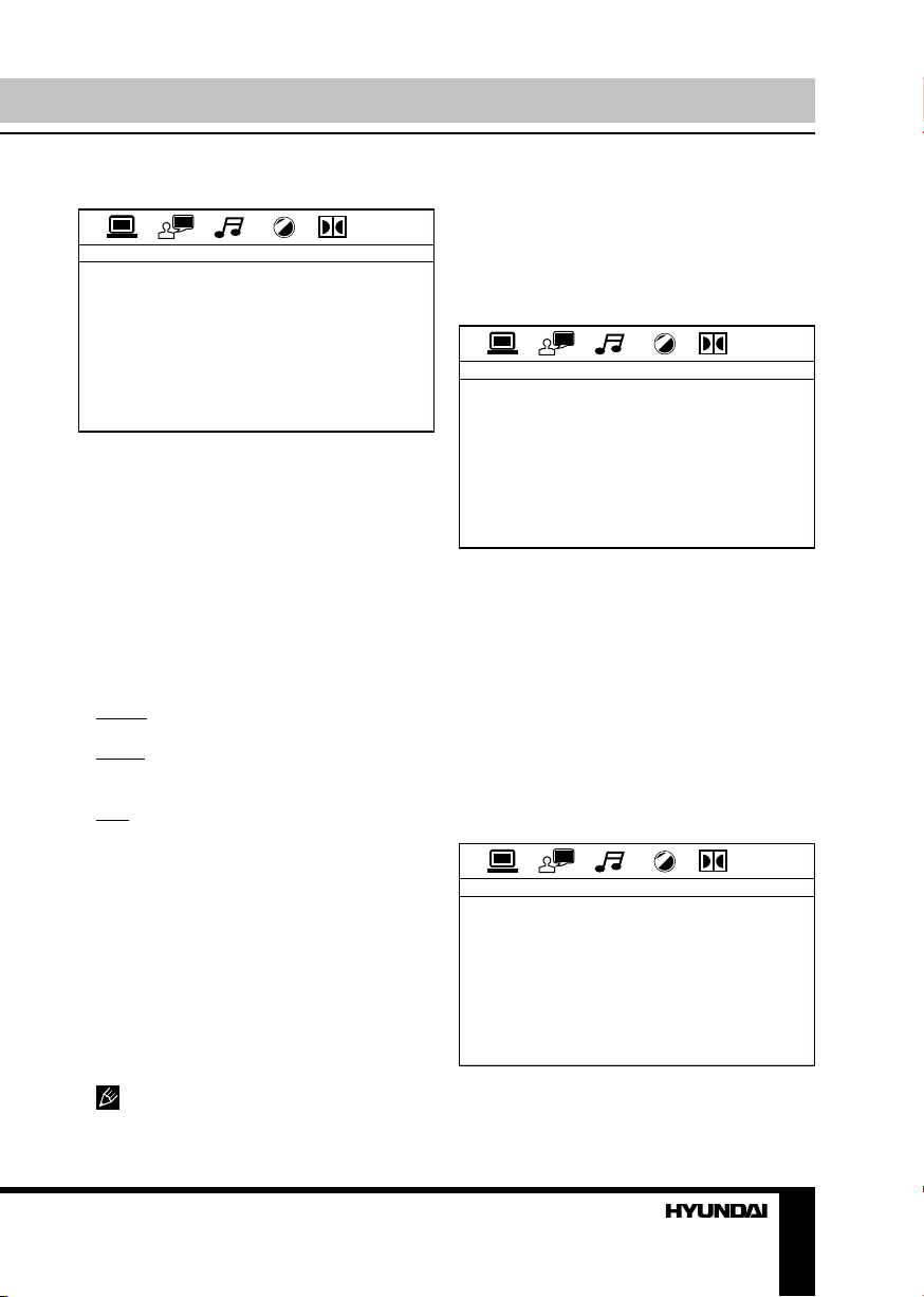
Системные настройки
СИСТЕМНЫЕ НАСТРОЙКИ
СИСТЕМА ТВ
ЗАСТАВКА
ВИДЕО
ФОРМАТ ТВ
ПАРОЛЬ
ОГРАНИЧ.
ЗАВОДСКИЕ
Система ТВ
Выберите систему ТВ (NTSC, PAL, PAL60,
АВТО).
Заставка
Заставка появляется через несколько
минут после остановки диска. Исходная
установка: Включено.
Видео
Чересстрочная развертка (interlace-SVideo).
Формат ТВ
Выберите режим экрана для просмотра
широкоэкранных фильмов.
4:3 PS: Для размера экрана 4:3. Края
изображения будут обрезаны.
4:3 LB: Для размера экрана 4:3, сверху
и снизу изображения появятся черные полосы.
16:9: Для размера экрана 16:9.
Пароль: Исходный пароль – 0000.
Ограничение
Эта функция предназначена для контроля
родителями за содержанием дисков при их
воспроизведении и защищает Ваших детей
от сцен насилия и эротики. Диск, уровень
которого выше, чем установленный с помощью данной функции, не будет воспроизводиться.
Рейтинг диска от 1 до 8:
(1) С высоким уровнем ограничения.
(8) С низким уровнем ограничения.
Исходная установка: 8
Вы можете установить рейтинг
только при выключенной функции пароля.
Ограничения будут действовать только при
включенной функции пароля.
Заводские установки
При выборе этого параметра телевизор
вернется к исходным заводским установкам.
Установка языка
УСТАНОВКА ЯЗЫКА
МЕНЮ
ЗВУК
СУБТИТРЫ
МЕНЮ ДИСКА
DIVX [R] VOD
Системный
Выберите язык экранного меню.
Аудио
Выберите язык аудио. Вы также можете
выбрать язык из предложенных на DVD
диске.
Субтитры
Выберите язык субтитров. Вы также
можете выбрать язык субтитров из предложенных на DVD диске.
Меню диска
Выберите язык меню диска.
Аудио настройки
АУДИО УСТАНОВКА
ТОН
Тон
Настройте данный параметр с помощью
кнопок курсора ВВЕРХ/ВНИЗ.
Page 42

Управление устройством Общая информация
Настройки видео
НАСТРОЙКИ ВИДЕО
ЯРКОСТЬ
КОНТРАСТ
ЦВ. ТОН
ЦВЕТНОСТЬ
ЧЕТКОСТЬ
Настройте нужный параметр изображения с помощью кнопок курсора ВВЕРХ/
ВНИЗ: Яркость, Контрастность, Оттенок,
Цветность, Четкость.
Цифровые настройки
ЦИФРОВАЯ УСТАНОВКА
ДИН. ДИАПАЗОН
РЕЖИМ ЗВУКА
Динамический диапазон
При просмотре в ночное время программ
с высоким динамическим диапазоном звука
выбор этого режима позволит Вам установить такой формат обработки звука, который
позволит сохранить качество и детали звукового сопровождения. Это даст Вам возможность не беспокоить остальных членов семьи
и сохранить высокое качество звука.
При выборе пункта “Full”, аудио сигнал
будет минимальным, при выборе “Off”,
аудио сигнал будет максимальным.
Режим звука
Выберите канал аудио сигнала: Стерео,
Моно левый (левый L), Моно правый (правый R), Смешанный моно (L+R).
42 43
Page 43
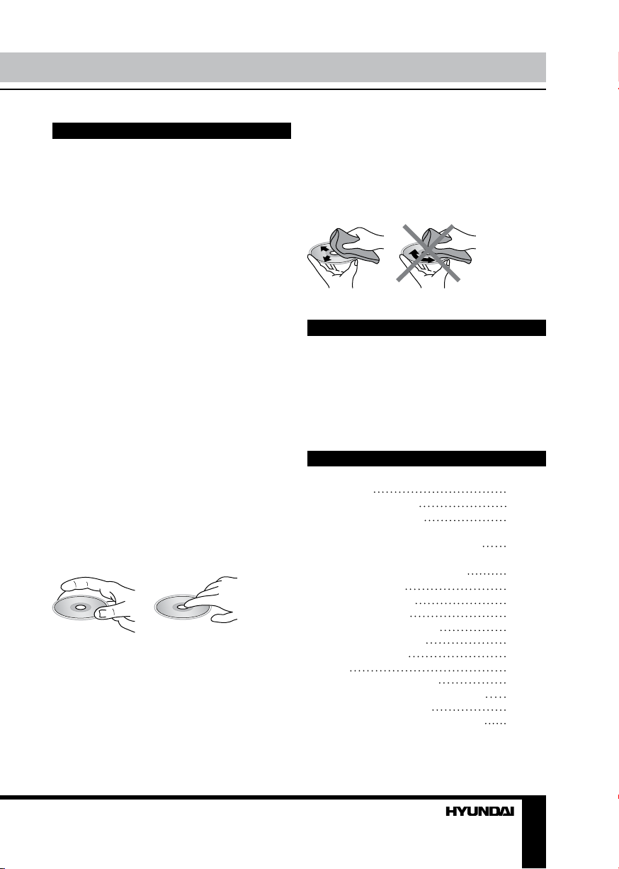
Обращение с компакт-дисками
• Не вставляйте в слот для загрузки
компакт-диска ничего, кроме компактдисков.
• Не используйте диски с трещинами,
отколотыми краями, деформированные
диски или диски с другими повреждениями, поскольку такие диски могут вызвать
искажение звука, шумы или повредить
проигрыватель.
• Держите диск только за края (как показано на рисунке). Чтобы обеспечить чистоту
диска, не прикасайтесь к его поверхности.
• Когда диски не используются, храните
их в футлярах.
• Не подвергайте диски действию
прямого солнечного света, повышенной
влажности, повышенным температурам или
действию пыли.
• Продолжительное влияние предельных
температур (например, при пребывании
дисков в автомобиле в летнее время) может
деформировать диск.
• Не приклеивайте этикеток, не пишите
и не наносите химических веществ на поверхность дисков.
• Не прикасайтесь к записанной поверхности дисков.
• Используйте только традиционные
круглые диски диаметром 12 см. Не используйте диски необычной формы и нестандартного размера.
Чистка дисков
Отпечатки пальцев должны быть тщательно стерты с поверхности диска мягкой
тканью. В отличие от обычных пластинок,
компакт-диски не имеют канавок для сбора
пыли и микроскопических частиц грязи,
поэтому осторожно вытирайте их мягкой
тканью, чтобы удалить частицы грязи.
Вытирайте прямолинейным движением от
центра к краю.
Не используйте растворитель, бензин,
очиститель пластинок или антистатический аэрозоль для чистки дисков. Такие
химические вещества могут повредить его
пластиковые поверхности.
Чистка корпуса устройства
Протирайте поверхности устройства мягкой тканью. Не мочите корпус. Если корпус
очень загрязнен, используйте ткань, слегка
смоченную мыльным раствором, и затем
вытрите корпус сухой тканью.
Комплект поставки
1. Ресивер
2. Передняя панель
3. Защитный футляр
4. Пульт дистанционного управления
5. Комплект ISO-кабелей (А+В)
6. Детали для установки:
Шестигранная гайка M5 T
Ключ-съемник
Опорная планка
Плоская шайба
Декоративкая рамка
Пружинная шайба
Винт (5X25 мм)
Болт
Резиновая заглушка
7. Информация для потребителя
8. Гарантийный талон
9. Инструкция по эксплуатации
1 шт
1 шт
1 шт
1 шт
1 шт
1 шт
2 шт
1 шт
1 шт
1 шт
2 шт
4 шт
1 шт
1 шт
1 шт
1 шт
1 шт
Page 44

Общая информация Общая информация
Руководство по устранению
неисправностей
Ниже приводится таблица, в которой описаны простые проверки, способные помочь
Вам устранить большую часть проблем, могущих возникнуть при использовании данного
устройства. Если нижеуказанные меры не помогли, обратитесь в сервисный центр или к
ближайшему дилеру.
Неисправность Причина Решение
Если источник питания подключен
надлежащим образом к выключателю
машины, установите ключ зажигания в
положение “АСС”.
Отрегулируйте громкость звука до необходимого уровня.
Проверьте подключение кабеля.
Отрегулируйте угол установки, установив его менее 30 градусов.
Очистите диск или используйте новый
диск.
Извлеките диск из устройства, затем
установите новый диск.
В течение часа не пользуйтесь устройством, затем повторите попытку.
Установите диск стороной с маркировкой вверх.
Очистите диск или установите новый.
Подождите, пока температура не станет
нормальной.
Выполните перезапуск устройство с помощью кнопки RESET.
Установите заново переднюю панель.
Подключите к устройству кабель антенны.
Нет питания
Нет звука
Плохое качество
звучания
Диск не загружается или не
извлекается из
устройства
Устройство не
считывает диск
Не работают
кнопки
Радиоприемник
не работает
Зажигание машины не
включено.
Сгорел предохранитель. Замените предохранитель.
Уровень громкости звука
установлен на минимум.
Кабель не подключен над-
лежащим образом.
Угол установки устройства
более 30 градусов.
Диск загрязнен или имеет
дефект.
В устройстве уже есть
диск.
Конденсация влаги.
Диск установлен верхней
стороной вниз.
Диск загрязнен или имеет
дефект.
Температура внутри автомобиля очень высокая.
Встроенный микрокомпьютер не работает надлежащим образом.
Передняя панель установлена некорректно.
Кабель антенны не подключен к устройству.
44
Page 45

Не работает
автонастройка
радиостанций
Радиостанции имеют
слишком слабый сигнал.
Настраивайтесь на станции вручную.
Технические характеристики
Общие
Источник питания 12 В постоянного тока
Максимальная выходная мощность 4 х 50 Вт
Размеры устройства/вес нетто 178 х 50 х 178 мм/1,55 кг
Размеры коробки/вес брутто 280 х 103 х 225 мм/2,25 кг
Диапазон температур -200С - +600С
Дисплей
Дисплей Встроенный 3,5-дюймовый TFT
Формат матрицы 16:9
Разрешение экрана 320 (RGB) х 240
Яркость 250 кд/м
Контрастность 500:1
Угол обзора 120°
Стерео FM радио
Частотный диапазон 65.0 - 74.0/87.5 - 108.0 МГц
Сохраняемые станции 18
Используемая чувствительность <15 дБ
MW радио
Частотный диапазон 522 - 1620 кГц
Сохраняемые станции 6
ТВ-тюнер
ТВ система SECAM/PAL
Плеер дисков
Система Дисковая аудио система
Поддержка носителей DVD/DVD±R/DVD±RW, CD/CD-R/CD-RW,
USB, SD/MMC
Воспроизведение форматов DVD-video/DVD-audio/SVCD/VCD/HDCD/
MP3/CDDA/CD/Picture-CD/Photo-CD/JPEG/
MPEG4 (DivX/XviD)
Электронная система стабилизации 8 сек. DVD, 40 сек. Audio-CD, 120 сек. MP3
Угол установки 0 - +/-30
2
0
Технические характеристики могут быть изменены заводом-изготовителем без предварительного уведомления. Указанные геометрические размеры имеют приблизительные
значения.
 Loading...