

Page 1
HYUNDAI DUCTLESS SPLIT SYSTEMS
SINGLE AND MULTI-ZONE
SINGLE ZONE
COOLING ONL Y
HACW09DB – HCCW09DB
HACW12DB – HCCW12DB
HACW18DB – HCCW18DB
HACW24DB – HCCW24DB
COOLING AND HEATING
HAHW12DB – HCHW12DB
HAHW18DB – HCHW18DB
HAHW24DB – HCHW24DB
○○○○○○○○
○○○○○○○○
MULTI-ZONE
COOLING ONL Y
HACM09DB – HCCM99DB
HACM12DB – HCCM22DB
COOLING AND HEATING
HAHM09DB – HCHM99DB
HAHM12DB – HCHM22DB
ECR INTERNA TIONAL
85 Middle Rd.
Dunkirk, NY 14048
Ph: (716) 366-5500
INST ALLATION MANUAL AND OPERA TING INSTRUCTIONS
Fax: (716) 366-1209
www.ecrinternational.com
○○○○○○○○
An ISO 9001-2000 Certified Company
Rev. 2.4 [08/04]
Page 2
SAFETY TIPS FOR OPERATION
! WARNING !
• Do not place animals, plants, or combustible equipment
in the path of the unit air flow.
• Do not touch the unit(s) with wet hands.
• Do not put anything in the air inlet(s) or outlet(s) especially
on the outdoor (condenser) unit. Children are particularly
liable to this danger. The fan is running at high speed
inside. Covering the units or blocking them will cause the
deterioration of air conditioner performance or cause malfunction.
• Do not apply excessive force to terminal connections.
• Connect the air conditioner(s) to a (dedicated) electrical
circuit.
• In the event of lightning, stop the air conditioner(s) and
disconnect the power source.
• Do not touch the heat exchanger, pipes and valves on the
outdoor unit during cooling cycle. You may get burned.
• The fuse or the circuit breaker must comply with national
and local codes.
! CAUTION !
• Never expose infants, handicapped persons, or seniors
directly to the airflow. Adjust the room temperature and
the airflow direction.
• Make sure that the indoor and outdoor unit(s) are installed
out of the reach of children.
• Do not use the air conditioner(s) for preservation of foodstuffs, animals, plants, precision appliances, arts and
medicine.
• Do not sit on or place objects on the unit(s).
• Use ASHRAE or MANUAL -J to calculate the cooling load.
• The current temperature indicated on the remote control(s)
can be different from the actual temperature of the room.
• Any function indicated by a * is limited to heating model
only.
• Do not modify the system(s). It may increase the risk of
fire.
FEATURES
DEODORIZING FUNCTION
In case of DRY and COOL mode, the fan or indoor unit(s) will
not turn ON for 40 seconds even after starting the operation in
order to deodorize various smells emitting from the inside of
indoor unit.
MELODY BUZZER
When selecting ON/OFF and function changes, a melody will
sound from the indoor unit(s) to indicate that the change has
occurred.
ECR International
Hyundai Ductless Split System2
Page 3
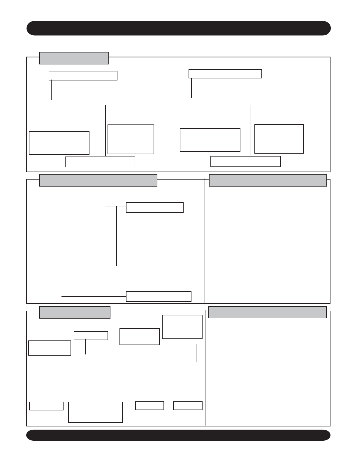
COMPONENTS AND FUNCTIONS
For the proper use, please check and identify the name and location of each part.
Indoor Unit(s)
Air Intake (Front, Top)
Left/Right Air Flow
Up/Down Air Flow
Direction Control Plate
(Page 6)
Air Filter (Inside)(Page 9)
Direction Control
Plate (Inside)
(Page 6)
Control Keys of Main Unit
09/12 Btuh 18/24 Btuh
Air Intake (Front, Top)
Up/Down Air Flow
Direction Control Plate
(Page 6)
Air Filter (Inside)(Page 9)
Left/Right Air Flow
Direction Control
Plate (Inside)
(Page 6)
Preparation For Use
09/12 Btuh System
(Single or Multi-Zone)
Hand Switch Lever
• During the season, set the Hand
Switch Lever to ON (I) position.
• After the season, set the Hand
Switch Lever to OFF (O) position.
Outdoor Unit
09/12 Btuh
Air Intake (Left
side, Rear)
Air Outlet
Drain Hose
Interconnection
cable, pipes and
power supply
18/24 Btuh System
(Single Zone Only)
• The Remote Control is stored inside
the product. Please open the front
grill to remove the Remote.
Remote Control Storage
18/24 Btuh
Air Intake (Left
side, Rear)
Air Outlet
Interconnection
cable, pipes and
power supply
Drain Hose
1 Lift up the front grille.
2 Turn the Hand Switch Lever
to ON position.
Mode of Operation Indicator
Operation Lamp
Timer Lamp
Heat Operation Lamp
Sleep Lamp
High Power Lamp
ECR International
Hyundai Ductless Split System3
Page 4

PART NAME OF REMOTE CONTROL AND KEY FUNCTION
Operation starts by manipulating the Remote Control. Please check and identify the name and location of part.
CLOSED
Transmitter
Low Battery Indicator
Display Window
ON/OFF Button
Temperature Setting Button
High Power Button
One Hour Timer Button
ON-Timer/OFF-Timer
Selector Buttons
OPEN
ACL Button
Timer Setting/Temperature Setting
Operation Mode Selector Button
Selects the mode (AUTO, HEAT, DRY,
COOL, CIRCULATE)
Airflow Direction Button
Up/Down Air Flow Direction Control
Fan Speed Button
Sleep Operation Button
Timer Cancellation Button
Time Set Button
Celsius (°C) Fahrenheit (°F)
Selector Switch
Celsius (°C)
D
C
Fahrenheit (°F)
D
F
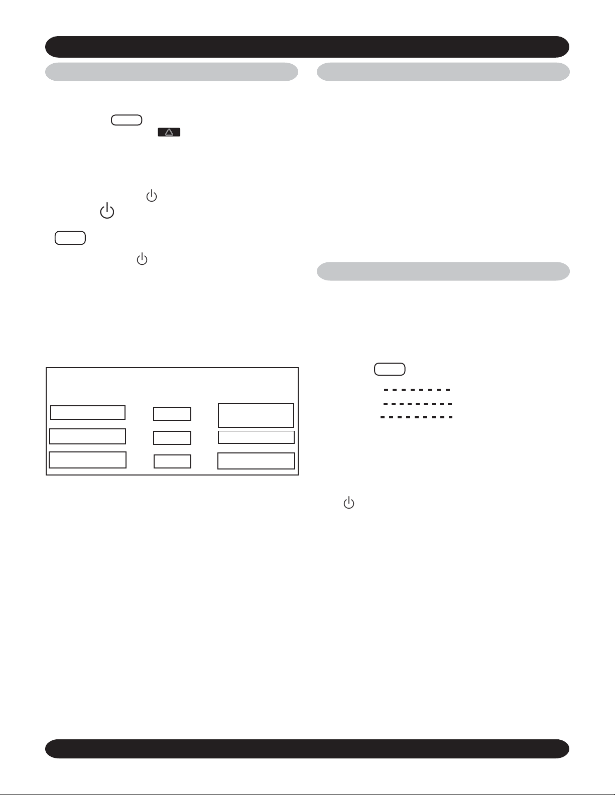
PREPARATION BEFORE OPERATION
INSTALLING BATTERIES
1. To lift the cover press in
and up on the lid latch with
your thumb nail.
2. Insert two (2) (AAA) size
batteries according to the
plus (+) and minus (-) markings. Always use Alkaline
batteries.
3
3. Replace cover.
4. Press the “ACL” button on
the face of the Remote.
1
“AM 12:00”
Blinking
2
ACL Button
(Front Cover)
Cover
CURRENT TIME ENTRY
(Example) Setting AM 10:00;
1. Set time AM 10:00 by pressing
button.
1
2
NOTE: If current time is not set correctly, the timer will
not operate normally.
ECR International
• Time can be adjusted by pressing
and holding the button. It can also be
adjusted in one minute intervals by
single pressing and releasing the
button.
2. Set current time by pressing
button.
INSTALLING REMOTE
• When it is attached to the wall.
• Place the bottom of the Remote Control on the hook first
and then push it into the holder.
NOTE: The transmitting distance may be shorter in a place where the
room has electronic lighting equipment.
• If the batteries are not in use for a prolonged period of time, remove
them from the battery compartment to avoid undue draining.
• The batteries can be used for about 6 months. If the Remote Control
is not operating even when placing it near the receiver, replace
them with 2 new batteries and press the ACL button.
• Please do not use manganese batteries. It may cause the remote to
malfunction.
• Avoid extremely hot or cold locations such as placing it near or over
a radiator, or in direct sunlight. Also avoid placing it near fluorescent lighting.
• Do not let children play with the Remote Control.
• To avoid interference, the indoor unit and the Remote control unit
should be at least 3 feet away from a TV set or a radio.
• In cases where than two air conditioners are installed in the same
room, individual operation may not be possible.
CONTROL HOLDER(S)
2
Push
1
Place
! CAUTION !
Hyundai Ductless Split System4
Page 5
OPERATION
AUTO OPERA TION
• Air-Conditioner(s) automatically selects the
proper room temperature.
1. Press the MODE button on the Remote Control, and select AUTO ( )mode.
2. Press the ON/OFF button.
STOP
Press the ON/OFF button again.
• Auto Mode controls every function of the air conditioner in
order for you to feel as comfortable as possible.
• The operation is automatically controlled according to
the room temperature and humidity. (When you turn on
the unit again within 2 hours of operation, the operation
proceeds in the same way as before.)
DRY MODE
• If you want the room thermostat to monitor the difference
between room temperature and set temperature, select
either COOL or DRY mode.
• In the DRY mode, the fan is running to remove the humidity without dropping the room temperature.
• If Dry mode is selected, the Indoor/Outdoor Unit(s) can
be controlled very precisely and the humidity inside the
room is removed. Recommended at humid weather such
as rainy days, etc. When outside temperature is too low
or room size is too small, the room temperature may go
down further than the set point.
• When the room temperature is below 59° F , the operation is stopped and the unit is switched to the Wait Mode
at which time the room temperature is monitored.
MANUAL OPERATION
• In case you are not satisfied with various conditions of
automatic operation, you can select these conditions as
you wish.
• Select HEAT, DRY, Cool or CIRCULATE mode as you wish.
Room
Temperature
Over 27°C (81°F)
20~27°C (68~81°F)
Below 20°C (68°F)
• The room temperature is adjustable as you desire by
pressing the room temperature setting.
• The adjustable range is up to 4°C (8°F) plus or minus.
• Automatic operation will not show the set room temperature.
• The room temperature automatically appears in the display indicator about 5 seconds after adjustment.
Operating
D
D
D
Mode
Cool
Dry
Heat
Set Temp.
26°C (79°F):18/24K
D
27°C (81°F):9/12K
D
D
24°C (75°F)
Monitor
1 Press the MODE button on the Remote Control.
• Cold weather
• High humidity
• Hot weather
• When air circulation is needed
HEA T mode
DRY mode
COOL mode
CIRCULA TE mode
2 Press the ON/OFF
button
When the fan speed or air flow direction is to be changed.
• When the set temperature is to be changed:
Press the SET TEMP button.
Each press changes
unit of temperature 1° F.
ECR International
°°
°°
16
°C (61
°F)
°°
°°
Lower Limit
Hyundai Ductless Split System5
Temperature Range
°°
°°
30
°C (86
°F)
°°
°°
Upper Limit
Page 6
OPERATION (Continued)
HEAT MODE (Except Cool model)
Heating Capability:
~ This is a Heat pump type air conditioner which is heating
the room by absorbing the outside air to the room. Therefore, as outside temperature drops, heating capability may
be reduced.
~ If heating is not enough, please use another heating source
together with the unit(s).
• This is a warm air circulating system for heating the room.
Therefore it will take time to heat the whole room.
Features of Heating Operation:
~ If there is frost on the outdoor unit, the heating capacity
will drop. Therefore, defrosting operates automatically
(approx. 5 to 12 minutes) and the indicator light on the
indoor unit(s) will blink (red).
~ The room and outdoor fan does operate during defrosting
and the unit will not run during this time.
! CAUTION !
• In case of Cool and Dry mode, water may drop according
to the contaminating status of air filter. In this case, please
clean or replace the air filter with a new one.
• To change the air flow Up or Down
Press the Flap button.
• Up/Down Moving
range of Airflow
Direction Control
Plate.
• Left-right airflow direction is adjusted manually.
• As shown in the figure below adjust the left-right airflow
direction with the right/left air flow control plate.
F AN SPEED, AIR FLOW DIRECTION
• To operate the unit(s) effectively, it is recommended that
you familiarize yourself with the following functions:
• To change the fan speed
Press the FAN SPEED button.
• Cold air moves down, horizontal air flow is preferred when
cooling.
• Up/Down Air Flow
Control Plate
• Right/Left Air Flow
Control Plate
CIRCULATION MODE
• If CIRCULATION mode is selected, the room air is circulated so that the temperature stratification in the room will
be reduced.
• You can select AUTO, HIGH, MED, or LOW speed.
• In the AUTO fan speed, the room temperature, set temperature and the unit temperature are monitored so that
the circulation can be properly controlled.
ECR International
Hyundai Ductless Split System6
Page 7

OPERATION (Continued)
TIMER MODE (ON, OFF)
• The timer can be set during any mode.
Select the timer setting by pressing:
ON-TIMER button or OFF-TIMER button.
(Example)
Time is AM 10:20. Air-conditioner is not in operation.
How to start the air conditioner at PM 1:30 and stop it at
PM 6:30.
1. Press the
2. Press button to adjust ON TIMER to PM 1:30 (Time
can be adjusted at hour intervals by pressing and holding
button. Time can also be adjusted by 10-minute
intervals by pressing button at center interval.
3. Press the TIMER button.
4. Press the button.
button.
mark will blink
OPERATION CONDITION
• Operation Temperature Range:
HYUNDAI OPERATING RANG ES
Mode
Cool
Dry
Heat
• If you operate the unit(s) at other than the above conditions, a safety device may be activated and shut off the
power.
• On humid days, frost may form on the surface of air conditioner or condensation may occur.
Temp eratu re ( °F)
Indoor Outdoor
70-90 70-109 <80%
59-90 59-109 <80%
59-81 32-75 <80%
Indoor
Humidity
HIGH POWER MODE
Convenient on a hot day. (During AUTO, HEAT, COOL or DRY
mode)
Press the HIGH POWER button.
mark will blink
5. Press button to adjust OFF TIMER to PM 6:30
Time can be adjusted at hour intervals by pressing
and holding button. Time can also be adjusted
by 10-minute intervals by pressing button at
center interval.
6. Press the TIMER button.
T o CANCEL Press the “C” button.
Check if current time is set correctly.
If current time is not correct, timer will not operate at desired time.
T o CANCEL:
Press the HIGH POWER button once more. The operation
is set back to the previous
operation mode.
HIGH POWER MODE
When the HIGH POWER mode button is pressed, heated or
cooled air comes into the room at a higher fan speed for 15
minutes. The fan speed changes rhythmically between high
and ultra-high.
! CAUTION !
When the air conditioner(s) continue to run on HIGH
POWER mode in a large room, they may not reach the set
room temperature due to limited cooling capacity. This
may cause water drops to form around the outlet. In such
cases, please switch to MANUAL mode.
ECR International
Hyundai Ductless Split System7
Page 8

OPERATION (Continued)
SLEEP MODE
The desired room temperature is maintained quietly at lower
fan speed. (During AUTO, HEAT, COOL or DRY mode)
Press the SLEEP button.
To CANCEL:
Press the SLEEP button
once more. The mode is
set back to the previous
operating mode.
SLEEP MODE
• Decreases the fan speed of Indoor Unit(s) automatically
and quiet operation is carried out.
• When Sleep mode starts to operate, desired temperature
will change automatically (see below).
Heat*
Cool & Dry
3°C(6°F) down an hour after
4°C(8°F) down another 3-hours after
1°C(2°F) go es up an hour after
NOTE:
• If pressing the 1HR TIMER button again during the
ONE HOUR TIMER mode, the unit will stop operation approximately one (1) hour later.
• The ONE HOUR TIMER mode has preference over other
Timer modes. If pressing the 1HR TIMER button again
during the OFF TIMER mode, the unit(s) will stop operating approximately one (1) hour later.
EMERGENCY OPERATION
When the remote control cannot be used due to dead batteries
or out of order, use the Hand Switch Lever.
After turning the Hand Switch Lever to OFF “O” position, turn it to
ON “I” again.
The lamp will light and the unit(s) will start in the Automatic
operation mode.
9/12 Btuh
18/24 Btuh
• When sleep mode starts to operate, flaps will move up or
down by one-step automatically.
Cool/Dry
Heat*
Move up by one-s tep
Move down by one-s t ep
1HR TIMER MODE
• This mode is convenient to use before sleeping or leaving.
Press the 1HR TIMER button.
To CANCEL:
Press the ON/OFF
button. This will stop the
ONE HOUR TIMER operation. Then press the ON/OFF button again, the unit will be set
to the previous operating mode.
• Upon input, one-hour timer is set at display and 0:30 is
indicated current time.
• If 1hr timer is set, the remaining minutes will be indicated.
T o STOP: T urn the Hand Switch Lever to OFF ”O” position.
ECR International
Hyundai Ductless Split System8
Page 9

MAINTENANCE
ROUTINE MAINTENANCE
• Be sure to stop the operation and disconnect the power
source before performing any checks or cleaning.
• Do not wet the air conditioner(s).
• Benzene, thinner and cleaning powder may damage the
coated surface or the plastics.
• Do not use water higher than 40° C (104° F), or the air
filters may shrink and the plastic materials may be damaged.
• Do not touch the evaporator coil when removing and replacing the air filters. Injury may occur.
• Never operate the unit without the air filters.
1. CLEANING AIR FILTERS (ONCE EVER Y TWO WEEKS)
Clean the air filters at least once every two weeks to save electricity. Use the vacuum cleaner to remove dust from the air filter.
NOTE: In case the dust on the air filter cannot be easily
removed with a vacuum cleaner, use a neutral cleaning agent. Be sure to sufficiently rinse the air filter with
water to completely remove the cleaning agent and
allow it to dry in the shade.
How to remove air filters:
A) Pull the front grille by grasping the recesses on the ends.
B) Open the front grille up to the position where it is stopped
with a click sound.
C) Raise the air filter, disengage the claws, and remove.
OPERATION MODE (Continued)
How to replace air filters:
A) Place the air filters with “Front” marking facing toward you
in the reverse order of mentioned “How to remove air
filters”.
B) Gently push to close the front grille to the unit.
C) Secure the grille in position by pressing evenly along the
lower edge.
2. CLEANING INDOOR UNIT(S) & REMOTE CONTROL(S)
Use a dry cloth for cleaning the indoor unit(s) and remote
control(s).
BEFORE THE SEASON
• Check that the air inlet and outlet of the indoor and outdoor
units are not blocked.
• Check that the ground wire is connected and there is no
wire breaks anywhere.
• Check that the installation bracket is not corroded or rusty.
• Check that the air filters are clean and in place.
AFTER THE SEASON
• Operate on “CIRCULATION” only mode for several hours
on a dry day . S torage when wet will allow mold to develop.
• Disconnect the power source
• Remove the batteries from the remote control.
• Clean the air filters and replace.
BEFORE CALLING FOR SERVICE
THE FOLLOWING ARE NOT DEFECTS
• A hissing noise or hollow sound:
This sound may be generated from the refrigerant flowing
within pipes during operation or after turning off the unit(s).
• A squeaking noise:
This noise is generated from the air conditioner(s) when it
expands or contracts due to temperature changes.
• A rustling noise:
This noise is generated from the indoor fan at start up.
• Operating sounds may change:
The operation sounds varies with the fan speed.
• Odors:
Such odors as tobacco, cosmetics, or foods may accumu-
late in the indoor unit(s).
• Indoor fan motor(s) stop:
In the “AUTO”, “DRY” and “HEAT” operation mode, the in-
door fan motor(s) will be stopped when the room temperature reaches the set temperature.
ECR International
• The air conditioner(s) do not start or change operation
mode immediately:
To prevent overloading the compressors, the air
conditioner(s) will not start for approx. 3 minutes.
• No change on the operation mode by the remote control:
The signal of operation mode changing has not reached
the indoor unit(s). Press the ON/OFF button again and
change the operation mode.
• The fan speed of the indoor fan motor changes or the
fan motor of the outdoor unit stops:
To prevent overloading the unit, the air conditioner(s) may
change the indoor fan speed and operate the outdoor fan
intermittently.
• In heat mode water comes out the outdoor unit:
The ambient air can condense on the pipes of the outdoor
unit.
Hyundai Ductless Split System9
Page 10

BEFORE CALLING FOR SERVICE (Continued)
PLEASE CHECK THE FOLLOWING
THE UNIT(S) WON’T OPERA TE
Check the batteries in the Remote Control.
Check that the power source is connected properly.
Check if the in-house fuse and/or breaker is “ON”.
Check to see if the power is on.
Check if the air filters are dirty.
Check if the room temperature setting is correct.
Check the horizontal louver.
Check to see if the air intake or the discharge outlet
Check if the air flow rate is correct.
COOL OPERA TION IS NOT SA TISF ACTORY
have been blocked.
CALL FOR SERVICE
• If the air conditioner(s) still have problems, disconnect the
power source and consult your installer.
• If water drips from indoor unit(s).
• If the circuit breaker frequently trips.
TROUBLE CHECK BY SELF-TEST MODE
• If an abnormality occurs on the air conditioner(s), the operation is automatically stopped by the “Self-Diagnosis Function”.
• If foreign substances or water entered the internal system
of the air conditioner(s).
• If it sounds strange during operation.
• If indoor unit(s) are not level.
• If the operating light of main unit is blinking, please put the switch lever(s) on the indoor unit(s) in off (O)-position.
9/12 Btuh
·
St ate of LED
18/24 Btuh
·
Trouble Che ck by Self-Test Mode
( )
Trouble Check by Self-Test Mode
Contents of Defec t
(Green) LED
(Orange) LED
(Green ) L ED
(Re d ) LED
(Green ) L ED
Contents of De fect
Defect of room temperat ure s ens or
·
Defect of indoor heat exchanger sens or
·
Defect of compressor protection circuit
·
(Cooling only M odel)
Defect of room temperature s ensor
·
Defect of indoor heat ex c hanger s ens or
·
:Blinking
·
:Blinking
·
When self-diagnosis is cleared it returns to normal operation.
ECR International
Hyundai Ductless Split System10
Page 11

INSTALLATION (Single Zone Shown)
Parts of Indoor Unit
No. Part Qty
Remote Control
1
Remote Control
Fixture
2
Batteries 'LR03'
3
(AAA)
1/unit
1/unit
2/unit
Distance between the
unit(s) and the wall should
be more than 6”
4 Manual 1
Part s of Out door Uni t
No. Part Qty
9/12 B tuh
1
R ubber Cushion
18/24 B tuh
2
R ubber Cushion
D rain Pipe
3
! CAUTION !
• Read this installation manual thoroughly before installing
the air conditioner(s) for proper installation.
• All field wiring must be installed by a licensed electrician
and must comply with all national and local codes.
• All field piping must be installed by a licensed refrigeration
technician and must comply with all national and local
codes.
• Never plug unit(s) into an electrical outlet.
• Do not touch compressor, pipes and valves without protective gloves during and after operation, because these
parts may become hot (more than 100°C (212°F).
• Explain the operating procedure of the air conditioner to
the customer.
4
4
(8.86”) 9 Btuh
(11.02”) 12 Btuh
1
(14.25”) 18/24 Btuh
Clearance in front of unit(s)
should be no less than 10’
Fasten the unit(s)
on the lower hook
of wall plate
(22.72”) 9/12 Btuh
(23.94”) 18/24 Btuh
Outdoor unit mounting
leg dimension
More than 2”
More than 16”
Outgoing tubing
(bottom)
Distance between the
unit(s) and ceiling should
be more than 2”
Connecting wire
More than 12”
Fasten the unit(s) on the
upper hook of wall plate
Distance between
the unit(s) and the wall
should be more than 6”
Wall plate
Patch
Wall cap
Through the wall
tubing (O.D. 2.36”)
NOTE: Always check superheat
and subcooling of system.
• Height limit: below 25ft.
• Maximum tubing length: below 50ft.
Tubing length over 25ft.
9/12 Btuh (Single or Multi-Zone)
• Charge additional refrigerant amount,
additional refrigerant amount =0.22oz./ft.>25’.
18/24 Btuh (Single Zone Only)
• Charge additional refrigerant amount,
additional refrigerant amount =0.44oz./ft.>25’.
• Capacity drops slightly.
More than 4”
More than 10”
DETERMINATION OF INST ALLING POSITION
! CAUTION !
• Make sure that the indoor unit(s) are installed high enough, over
6 feet, (beyond reach of young children).
Indoor Unit
• Do not install the unit(s) near a heat source.
• Be sure that air outlet and inlet are not obstructed.
• Be sure all clearances are as specified in the above figure (front,
upper, left and right of the unit(s)).
• Allow convenient drainage and piping connection with the outdoor unit.
• Avoid installing the unit(s) in direct sunlight.
• Install the unit(s) on walls that can support their weight.
ECR International
Install the Air Conditioner(s) by taking into account
the following points, upon the customer’s consent.
• Be sure chosen location can properly support the weight of the
unit(s) and will provide adequate damping of vibration and noise.
Outdoor Unit
• Insure chosen location can provide adequate drainage and good
ventilation.
• Do not install in an area with flammable or corrosive vapors. Avoid
salty air or sulfuric gas areas.
• Be sure all clearances are specified in the above figure (front,
upper, left, right and rear of the unit) and also open on more than
two sides.
• Be sure hot exhaust and noise does not bother the customer or their
neighbors.
• Do not allow hot exhaust to blow directly on pets and plants.
Hyundai Ductless Split System11
Page 12

MOUNTING OF THE INSTALLATION PLATE
1. Position the installation plate and check that it is level.
IMPORT ANT: Always mount the installation plate horizontally by aligning the marking line with the thread or using a
level.
2. Mount the installation plate horizontally and securely on
structural members (studs, etc.) in the wall with four (4)
9/12 Btuh
2’ 6”
5.28” 6.89” 6.89”
1.38” .85”
2’ 2.25”
3.43”
5.79”
4.21”
installing screws. (See Fig. 1)
9
3. Make a 2
angled down to the exterior. (See Fig. 2)
4. Use a city grade wall pipe (outer diameter : 2
sleeve to protect the interconnection cable and the piping. (See Fig. 2)
Wall pipe
( field supplied
OD: 2 3/8”)
INSTALLA TION OF THE INDOOR UNIT(S)
/16” hole through the wall. Hole should be
Indoor Outdoor
Wall-Hook Plate Mounting
Approximately
3/16”– 3/8”
Fig. 2
3
/8”) as a
Fig. 3
4.31”
3.72”
12.60”
1.81”
18.74”5.04”
1.81”
Anchor plug hole
18/24 Btuh
6.63”
3.93”
1.40”
1.81”
1.81”
15.63”
3’ 2”
10.33” 10.33”
8.52” 8.52” 6.63”
Anchor plug hole
2.92”
3’ 4”
(Take care not to twist or crimp pipes during installation.)
! CAUTION !
When inserting the pipes, protect the ends from dust or moisture by covering the flare connections with a cap or tape.
5.53”
9.12”
1.18”
3.93”
9.84”
7.44”
Pipe hole Ø 2.56”
1.93”
Fig. 1
10.83”
Fig. 2
For Right Rear Sided, Right Sided and Lower
Sided Piping
NOTE: Do not apply excessive force to these parts.
1. For right side and lower side piping, cut the indoor unit
base(s) with a hacksaw and deburr the cut end with a
file. (See Fig. 5)
2. Hang the indoor unit(s) on the upper portion of the installation plate while inserting the vinyl-taped pipes through
the wall hole. Engage the lower projection with the claws
of the installation plate. (See Fig. 7)
NOTE: Make sure that the unit(s) are securely mounted, by
slightly shaking the indoor unit(s).
Right rear sided
(recommended)
Right sided
Fig. 4
Interconnection cable
Indoor unit pipes
Indoor unit drain
hose
Vinyl tape
Cut here
Lower sided
Hacksaw
Fig. 6
Fig. 5
Fig. 7
ECR International
For Left rear Sided and Left Sided Piping:
(See Fig. 8)
Fig. 8
Left rear sided
Suction pipe
Left sided
The length of the cable
which will be passed
through the wall hole
should be longer than 40”.
Discharge pipe
Dimensions from the
center of the installation plate for reference.
4”
6”
Fig. 9
1. Regarding the left rear sided and left sided piping, the pipes
must be connected indoors and must be adjusted to the
actual installing length. Keep these pipes unrolled (See
Fig. 9 and Fig. 10)
2. For left side piping, cut the indoor unit base(s) with a hacksaw and deburr with a file.
3. Connect the indoor pipes and check for gas leaks.
(See Fig. 10) After the leak
test, wrap the flared
joints with insulation
and fix it with bands.
4. Remove the spacer
Fig. 10
Flare Coupling
installation
Discharge pipe
Suction pipe
Band
Tape after
finishing
leak test
Wall hole
from installation plate.
Suction pipe
Discharge pipe
Interconnection cable
Indoor unit drain hose
Hyundai Ductless Split System12
Page 13

INSTALLING OF THE OUTDOOR UNIT
• See the “Determination of Installing Position”.
Connecting of Tubing
1. Cutting and flaring of
tubing:
A. Cut the tubing on its
Cut pipe by rotating the
pipe cutter
Pipe
straight part with the
pipe cutter.
B. Remove burrs from cut
Turn the handle
Clockwise while
pushing it against
the pipe
edges of pipes, which
may cause a gas leak.
C. Flaring of the pipe is
done with the flaring
tool.
Do not damage the inside of the
pipe.
NOTE: Do not forget to in-
stall the flare nut before
flaring
2. Pre-Connecting:
Fix pipe
turning clamp
handle.
Flare nut
Bar
Screw the tubing turning
3 to 5 times until hand
Pipe
tight.
3. Fastening:
Fasten the connection.
Pipe cutter
knife
Yoke
Diagram 1
Discharge
Suction
UNIT
INDOOR
Flare nut Flare valve
(SINGLE ZONE SYSTEM SHOWN)
UNIT
OUTDOOR
Manifold gauges
Vacuum pump
Charge
cylinder
Leak Test
Leak Check
Check the joints with a gas
leak detector or soapy water for
refrigerant leaks. If a leak is
found, repair and recheck.
Drainage
Indoor Unit
After the indoor unit(s) have been installed, make sure that
condensed water is properly drained. (If this is neglected,
the unit(s) may become flooded.)
Special care should be given to the following details:
• Apply refrigeration oil to
the flare surface to prevent gas leakage.
Air Purge and Charging
! CAUTION !
1) Remove the cap from the service port on the suction line service
valve.
2) Connect the suction side of the refrigerant gauge manifold to
the Suction Line service valve. Connect the center hose of the
refrigerant manifold gauge to the micron gauge. Connect the
other side of the micron gauge to the vacuum pump. (Diagram 1)
3) Open the suction side of the refrigerant manifold set and turn
the vacuum pump on. NOTE: Evacuate the system down to
400 microns.
4) When the system pulls down to 400 microns turn the vacuum
pump off. Observe the micron gauge: if the system has a leak
the gauge will detect it. If there is a leak, find it, repair it, and
repeat steps 3 and 4.
5) Close the refrigerant gauge manifold valve and disconnect the
vacuum pump from the system.
6) Remove the Suction and Liquid line Service V alve Caps from the
valves.
7) Using an Allen wrench, open the Liquid Line Service Valve until
the valve is in the fully open position. Next do the same for the
Suction Line Service valve. NOTE: Be careful as not to
completely remove the valve core from the valve. This
will result in the release of refrigerant from the system
into the atmosphere!
8) Re-install the caps on both service valves. This completes the
charging of the system.
• Drain hose must
slope downward
to the outdoor
side.
• Do not use a trap
or kink.
• Never put the
end of the drain
hose into the
water.
• Do not tilt upward.
Outdoor Unit (Heat Pump Only)
NOTE: Allow clearance for drainage of water or condensate.
For outdoor condensation:
• The outdoor unit has drain outlets on the base to drain
condensation to the outside.
• To drain condensation by hose (5/8” hose) with the drain
socket, connect the socket to the center of the base and
cover all other outlets with base caps.
• Install the outdoor unit on a flat level surface and make
sure condensation drains smoothly.
• In cold areas, condensation
and defrost water can freeze,
therefore do not use the drain
outlet caps during the cold season.
• Electrical connection should
only be made by a qualified professional.
ECR International
Hyundai Ductless Split System13
Page 14

CONNECTING THE CABLE
• Use a dedicated circuit breaker for the air conditioner(s).
• When connecting the indoor unit(s) to the outdoor unit
please be sure to connect the same number on the
indoor and outdoor unit terminal blocks.
• Be sure to use approved connecting wire (14 gauge
minimum).
• When installing the air conditioner, please be sure to
use the right power supply cable conforming to Canadian Electrical Code/National Electrical Code.
NOTE: Interconnecting voltage is 208/230V.
• The air conditioner always requires grounding.
• Grounding must conform to local regulations.
HYUNDAI ELECTRICAL INTER-CONNECT
REVISION “B” PRODUCT
Cool Model
Cool and Heat Model
HHW12000/HMHW18000/HMHW24000
HHW18000/HHW24000
HCW9000/HCW12000/HMCW18000/HMCW24000
NOTE: For Multi-zone systems, there are two sets of iden-
tical wiring terminals. Be sure to match each air handler
with its corresponding terminal strip connection. Use above
diagram for each circuit.
HCW18000/HCW24000
! CAUTION !
Make sure wire connections are secure otherwise electrical malfunction may occur.
NOTE: Gnd is Earth Ground
HACW/HACM are cooling only indoor units
HCCW/HCCM are cooling only outdoor units
HAHW is heat pump indoor unit
HCHW is heat pump outdoor unit
! CAUTION !
• Connect one end of the ground wire to the outdoor
unit ground terminal.
• Use minimum 14 AWG wire conductors between the indoor and outdoor units.
• Refer to page 16 to determine the wire size from the power
supply to the condenser.
CONNECTING OF POWER SOURCE
! CAUTION !
Before supplying the power, check that the voltage is within
+6% of the rated voltage marked on the indoor unit label(s).
ECR International
Hyundai Ductless Split System14
Page 15

TEST RUN
• Be sure to check the power source, then turn the power on.
• Check the installation again.
• First, set the lever to OFF(O) position, then to ON(I) and
TEST position slowly. (During the test, the indicator light
will blink)
CABLE CONNECTION 9/12 Btuh (Single or Multi-Zone)
1. Wiring between units should be cut to length.
2. Remove the wiring cover of the Indoor Unit(s) and the Outdoor Unit.
3. Insert the connection wire into the terminal block.
• After the test, set the lever to ON (I) position. The unit will
stop the operation and hereafter the remote control will
control the unit.
9/12 Btuh
18/24 Btuh
ECR International
Hyundai Ductless Split System15
Page 16

CABLE CONNECTION 18/24 Btuh (Single Zone Only)
(5)
(1)
(2)
(3)
(4)
4. Fix the connecting wire between units, with wiring fixture.
5. Att ach the wiring cover.
ELECTRICAL SPECIFICATIONS AND SYSTEM PERFORMANCE
Single Zone
System
Cooling Capacity
(1)
Nominal
Sensible
HCW9000 9,500 7,030
HCW12000 12,000 8,760 10.6
Heating Capacity
SEER
10.9
(2)
(Btuh)
- -
-
HSPF Volts/HZ/Phase
HHW12000 12,000 8,760 10.4 12,500 7.2
HCW18000 20,000 14,200 10.7
- -
HHW18000 20,000 14,200 10.3 20,000 6.9
HCW24000 24,000 16,800 10.3
- -
HHW24000 24,000 16,800 10.0 24,000 6.8
(1) Indoor 80/67º F, Outdoor 95º F
(2) Indoor 70/58º F, Outdoor 47º F
Multi-Zone
System
HMCW18000
HMHW18000
HMCW24000
HMHW24000
(1) HMCW18000 consists of tw o HACM09DB (9,000 Btuh) air handlers and one HCCM09DB condenser.
(2) HMHW18000 consists of tw o HAHM09DB (9,000 Btuh) air handlers and one HCHM09DB condenser.
(3) HMCW24000 consists of tw o HACM12DB (12,00 0 Btuh) air handlers and one HCCM12DB condenser.
(4) HMHW24000 consists of tw o HAHM12DB (12,00 0 Btuh) air handlers and one HCHM12DB condenser.
(5) Indoor 80/67º F, Outdoor 95º F (6) Indoor 70/58º F, Outdoor 47º F
Cooling Capacity
(Btuh)
Nominal
18,000 12,600 10.9 - - 208/230/60/1 0.72 0.2 4.45 26 0.22 0.06 10.1 11 .1 15 197
17,400 11,700 10.0 17,700 6.8 208/230/60/1 0.72 0.2 4.45 26 0.22 0.06 10.1 11.1 15 197
24,000 15,500 10.6 - - 208/230/60/1 0.72 0.2 5.85 29 0.22 0.06 12.9 13.4 20 197
21,000 14,100 10.0 21,250 6.8 208/230/60/1 0.72 0.2 5.85 29 0.22 0.06 12.9 13.4 20 197
Sensible AMPS HP RLA LRA AMPS HP
SEER
Heating
Capacity
(6)
(Btuh)
HSPF Volts/HZ/Phase
Cond F an Mtr
COMPLETION OF INTERCONNECTING TUBING
Total
Amps
208/230/60/1 5.0 6.1 15
208/230/60/1
208/230/60/1
208/230/60/1
208/230/60/1
208/230/60/1
208/230/60/1
Compressor
Circuits 1 & 2
6.2 7.6 15
6.2 7.6 15
10.2 12.5 20
10.2 12.5 20
12.1 14.8 25
12.0 14.8 25
Indoor Fans Total
MCA
Amps
Max.
Fuse
MCA
HACR
BRKR
Min
Volt
• Insert the wall cap into the wall, and fill the gap with sealant to prevent rain or wind.
• When using the pipe cover, fill the gap in the wall through hole in the inside.
ECR International
Hyundai Ductless Split System16
Page 17

OPERATING CHARACTERISTICS (Single Zone Cooling)
All units operating on high speed fan
HCW9000 HCW12000
99
Outdoor Fan Speed
85
71
Low Pressure (PSI)
57
43
5
4.5 80
4
Running Current (A)
3.5
Low High
Room Temp. ( °F)
59 68 77 86 95 104
Outdoor Intake Temp. (°F)
Outdoor Fan Speed
Low High
Room Temp. ( °F)
59 68 77 86 95 104
Outdoor Intake Temp. (°F)
HHW12000
86
80
75
86
75
99
Outdoor Fan Speed
85
71
Low Pressure (PSI)
57
43
6.5
6.0
5.5
5.0
Running Current (A)
4.5
Low High
Room Temp. (°F)
59 68 77 86 95 104
Outdoor Intake Temp. (°F)
Outdoor Fan Speed
Low High
Room Temp. (°F)
59 68 77 86 95 104
Outdoor Intake Temp. (°F)
86
80
75
86
80
75
HCW18000
HHW18000
99
Outdoor Fan Speed
85 86
71
Low Pressure (PSI)
57
43
12
10 80
8
Running Current (A)
6
Low High
Room Temp. (°F)
59 68 77 86 95 104
Outdoor Intake Temp. (°F)
Outdoor Fan Speed
Low High
Room Temp. ( °F)
59 68 77 86 95 104
Outdoor Intake Temp. (°F)
HCW24000
HHW24000
80
75
86
75
99
Outdoor Fan Speed
85
71 80
Low Pressure (PSI)
57
43
13
12 86
11 75
10
Running Current (A)
9
Low High
Room Temp. ( °F)
59 68 77 86 95 104
Outdoor Int ake Temp. (°F)
Outdoor Fan Speed
Low High
Room Temp. (°F)
59 68 77 86 95 104
Outdoor Int ake Temp. (°F)
86
75
80
ECR International
Hyundai Ductless Split System17
Page 18

HHW12000
HHW18000
OPERATING CHARACTERISTICS (Single Zone Heating)
All units operating on high speed fan
HHW24000
ECR International
Hyundai Ductless Split System18
Page 19

OPERATING CHARACTERISTICS (Multi-Zone)
All units operating on high speed fan
HMCW18000
HMHW18000
99
85
71
57
43
59 68 77 86 95 104
5
4.5
4
Running Current (A) Low Pressure (PSI)
3.5
59 68 77 86 95 104
Room Temp. ( °F)
Outdoor Int ake Temp. (°F)
Room Temp. (°F)
Outdoor Int ake Temp. (°F)
HMCW24000
99
HMHW24000
86
80
75
86
80
75
85
71
57
43
59 68 77 86 95 104
8
7
6
5
Running Current (A) Low Pressure (PSI)
4
68 77 86 95
Room Temp. (°F)
Outdoor Intake Temp. (°F)
Room Temp. (°F)
Outdoor Intake Temp. (°F)
86
80
75
86
80
75
104
THERMISTER CHARACTER DIAGRAMS
ECR International
Hyundai Ductless Split System19
Page 20

 Loading...